THE BELT RAILWAY COMPANY OF CHICAGO TIMETABLE NO. 4 & Special Instructions EFFECTIVE 00:01 October 1, 2007 Michael A. Paras General Manager Transportation

Welcome message from author
This document is posted to help you gain knowledge. Please leave a comment to let me know what you think about it! Share it to your friends and learn new things together.
Transcript

THE BELT RAILWAY COMPANY
OF CHICAGO
TIMETABLE NO. 4 &
Special Instructions
EFFECTIVE 00:01 October 1, 2007
Michael A. Paras General Manager Transportation

Effective October 1, 2007 TIMETABLE / SPECIAL INSTRUCTIONS 2
TRANSPORTATION DEPARTMENT M. A. Paras General Manager (708) 496-4056 Fax: (708) 658-1510 M. R. Shore Superintendent (708) 496-4121 Fax: (708) 496-4135 R. E. Picken Ass’t Superintendent (708) 496-4058 Fax: (708) 496-4135 V. M. Bell Ass’t Superintendent (708) 496-2305 Fax: (708) 496-4135 C. D. Mowery Mgr Operating Practices (708) 728-2318 Fax: (708) 277-1702 Field Trainmaster (708) 259-5588 Hump Trainmaster (708) 259-5586 Command Center (708) 728-2259 Fax: (708) 728-3827 North Dispatcher (708) 496-4105 AAR Radio: 39-39 South Dispatcher (708) 496-4101 AAR Radio: 26-26 Humpmaster (708) 496-4053 AAR Radio: 57-57 West Yardmaster (708) 496-4130 AAR Radio: 18-18 East Yardmaster (708) 496-4128 AAR Radio: 89-89 ENGINEERING DEPARTMENT R. S. Strong Chief Engineer (708) 496-4033 Fax: (708) 496-8011 R. D. Smith Ass’t Chief Engineer (708) 496-4032 Fax: (708) 496-8011 MECHANICAL DEPARTMENT M. S. O’Donnell Superintendent (708) 496-4040 Fax: (708) 496-4005 W. W. Kizior Ass’t Superintendent (708) 496-4097 Fax: (708) 496-2301 H. Simon Ass’t Superintendent (708) 496-2242 Fax: (708) 728-2255 POLICE DEPARTMENT M. R. Romano Chief of Police (708) 496-4076 Police Emergency Number (708) 496-4133 Day Cell: (312) 543-8269 Toll Free: (877) 844-4911 Night Cell: (312) 543-3658 General Contact Number (708) 496-4072 Pager: (708) 396-4045 SAFETY HOT LINE (708) 496-4099 RECOGNITION HOT LINE (708) 406-2304 GRADE CROSSING HOT LINE (708) 728-3219

Effective October 1, 2007 TIMETABLE / SPECIAL INSTRUCTIONS 3
TABLE OF CONTENTS Subdivisions Page Special Instructions Page
Kenton Line ITEM 1: Maximum Speed 22 Stations 6 Speed Restrictions 7 ITEM 2: CORA 22 Bridge & Eqpt Weight Restrictions 7 Operating Characteristics 8 ITEM 3: Train Dispatcher Terriitories 22 911 Crossings 8 Radio Frequencies 9 ITEM 4: GCOR Changes 22 Special Conditions 9 Glossary – Speed Signals 22 South Chicago Industrial Lead 9 1.0 General Responsibilities 22 Commercial Avenue Yard 9 2.0 Railroad Radio Rules 24 South Chicago 9 3.0 Standard Time 24 87th Street Yard 9 4.0 Timetables 24 Rockwell Yard 9 5.0 Signals and Their Use 24 22nd Street Yard 9 6.0 Movement of Trains & Engines 24 7.0 Switching 26 59th Street 8.0 Switches 27 Stations 10 9.0 Block Signal Rules 27 Speed Restrictions 10 Bridge & Equipment Weight Restrictions 10 ITEM 5: Remote Control Zones 27 Operating Characteristics 10 911 Crossings 11 ITEM 6: AEI Site Locations 29 Radio Frequencies 11 Special Conditions 11 ITEM 7: Cold Weather Train Length 30 63rd Street 11 Elsdon Industrial Lead 11 ITEM 8: Clearances 30 Argo Industrial Lead 11 ITEM 9: Remote Control Operations 31 Clearing Yard Special Instructions Speed Restrictions 12 ITEM 10: Engineer Certification 37 Operating Characteristics 12 Requirements Radio Frequencies 13 Special Conditions 14 ITEM 11: BRC Speed Signals 40 Hump Approach Signals 14 Yard Air 14 ITEM 12: Hazardous Material Handling 42 Class 1 Air Brake Test 14 Instructions Central Avenue Crossing 14 Track Skates 14 ITEM 13: Security Alert Level 46 Hydraulic Retarders 14 Instructions Switches 15 Solar Powered Switches 15 Linear Operations Profile 49 Radio Controlled Switches 15 Hump Subway Switch 18 No. 7 Cross-over, West Rec. Yard 18

Effective October 1, 2007 TIMETABLE / SPECIAL INSTRUCTIONS 4
Effective October 1, 2007 TIMETABLE / SPECIAL INSTRUCTIONS 5
The Belt Railway Company
of Chicago
SUBDIVISIONS
Michael A. Paras General Manager Transportation

Effective October 1, 2007 TIMETABLE / SPECIAL INSTRUCTIONS 6
6.28
LENGTH OF SIDING
IN FEET
MILE POST
TRACK SOUTH NORTH STATIONS
RULE 4.3
METHOD OF
OPERATION
AEI SCANNER
CRAGIN(CP, METRA)
3.7 14th STREET
(CSX) 0.3
22nd St. YARD (MJ) 1.6
HAWTHORNE (BNSF, CN)
1.0 LEMOYNE (BNSF, CN)
1.7 55th STREET
(BRC 59th ST. SUB.) 1.7
67th STREET 1.4
EAST END SWITCHES (CN) 0.2
HAYFORD (CN) 0.8
ROCKWELL STREET YARD 0.6
WESTERN AVENUE (NS, CSX)
0.4 FOREST HILL
(CSX) 0.9
BELT JCT (NS, METRA)
1.5 80th STREET
(NS, METRA, UP) 1.0
87th STREET 2.7
PULLMAN JCT (NS, CN)
1.9 ROCK ISLAND JCT
(CRL, SCIH, NS, EJ&E, CSS&SB) 0.9
SOUTH CHICAGO YARD 1.7
END OF TRACK
0.0
3.7
4.0
5.6
6.6
8.3
10.0
11.4
11.6
12.4
13.0
13.4
14.3
15.8
16.8
19.5
21.4
22.3
24.0
YARD
3,057
YARD
12,000
YARD
YARD
2 MT
3 MT
2 MT
I J
J X2
J Y
X I J X
X I J X2
X I J X2
X2 I T
I J X2
X I J X
Y
I J X2
X I
I J X3
I J X2
Y
X I J X2
I J X2 Y
G Y
CTC
0.0
7.8
13.1
15.8
19.4
21.5
KENTON LINE SUBDIVISION
Effective October 1, 2007 TIMETABLE / SPECIAL INSTRUCTIONS 7
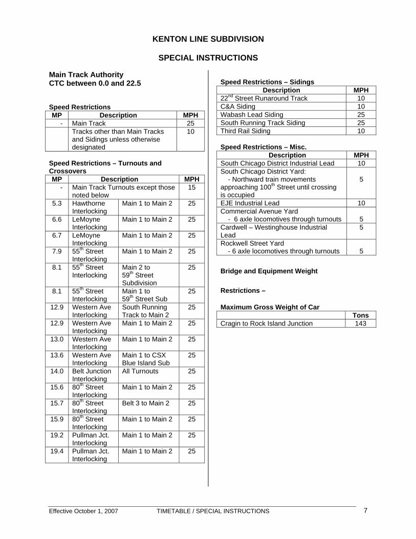
KENTON LINE SUBDIVISION
SPECIAL INSTRUCTIONS Main Track Authority CTC between 0.0 and 22.5 Speed Restrictions MP Description MPH
- Main Track 25 Tracks other than Main Tracks
and Sidings unless otherwise designated
10
Speed Restrictions – Turnouts and Crossovers MP Description MPH
- Main Track Turnouts except those noted below
15
5.3 Hawthorne Interlocking
Main 1 to Main 2 25
6.6 LeMoyne Interlocking
Main 1 to Main 2 25
6.7 LeMoyne Interlocking
Main 1 to Main 2 25
7.9 55th Street Interlocking
Main 1 to Main 2 25
8.1 55th Street Interlocking
Main 2 to 59th Street Subdivision
25
8.1 55th Street Interlocking
Main 1 to 59th Street Sub
25
12.9 Western Ave Interlocking
South Running Track to Main 2
25
12.9 Western Ave Interlocking
Main 1 to Main 2 25
13.0 Western Ave Interlocking
Main 1 to Main 2 25
13.6 Western Ave Interlocking
Main 1 to CSX Blue Island Sub
25
14.0 Belt Junction Interlocking
All Turnouts 25
15.6 80th Street Interlocking
Main 1 to Main 2 25
15.7 80th Street Interlocking
Belt 3 to Main 2 25
15.9 80th Street Interlocking
Main 1 to Main 2 25
19.2 Pullman Jct. Interlocking
Main 1 to Main 2 25
19.4 Pullman Jct. Interlocking
Main 1 to Main 2 25
Speed Restrictions – Sidings
Description MPH 22nd Street Runaround Track 10 C&A Siding 10 Wabash Lead Siding 25 South Running Track Siding 25 Third Rail Siding 10 Speed Restrictions – Misc.
Description MPH South Chicago District Industrial Lead 10 South Chicago District Yard: - Northward train movements approaching 100th Street until crossing is occupied
5
EJE Industrial Lead 10 Commercial Avenue Yard - 6 axle locomotives through turnouts
5
Cardwell – Westinghouse Industrial Lead
5
Rockwell Street Yard - 6 axle locomotives through turnouts
5
Bridge and Equipment Weight
Restrictions – Maximum Gross Weight of Car
Tons Cragin to Rock Island Junction 143

Effective October 1, 2007 TIMETABLE / SPECIAL INSTRUCTIONS 8
Operating Characteristics
Tracks Signal
System Rules
Main Track 1 & 2 between Cragin and Hayford CTC 10.1 Main Track 1, 2, Wabash Lead and South Running Track between Hayford Interlocking and Western Avenue CTC 10.1 Main Track 1 & 2 between Western Avenue and Belt Junction CTC 10.1 Main Track 1,2 & 3 between Belt Junction & 80th Street CTC 10.1 Main Track 1 & 2 between 80th Street and Rock Island Junction CTC 10.1 All Tracks between Rock Island Junction and End of track None 6.28 South Chicago District Industrial Lead None 6.28 EJE Industrial Lead None 6.28 South Chicago Commercial Avenue Yard None 6.28
Interlockings All Interlockings, with the exception of Forest Hill Interlocking, are controlled by the BRC Dispatcher. Forest Hill Interlocking is controlled by the CSX Dispatcher. 911 Crossings - Emergency Communication The following street crossings have been identified as critical routes for delivery of emergency services to the City of Chicago. When trains are stopped or anticipated to be obstructing any of these crossings for more than ten (10) minutes, train crew must notify the train dispatcher immediately. Upon receiving such notification, the train dispatcher will contact the City of Chicago Office of Emergency Communications and notify the Manager of Train Operations. A crew member must notify the train dispatcher when the train is clear of the crossing.
Subdivision Crossing Location Kenton Line Archer and Kolmar Kenton Line 4700 W. 55th Street Kenton Line 4700 W. 59th Street Kenton Line 4700 W. 63rd Street Kenton Line 4700 W. Marquette Kenton Line 2600 W. Columbus
Avenue

Radio Frequencies
Location AAR Frequency
BRC Frequency Contact Number
North Dispatcher - Kenton Line Subdivision, Cragin to and
including 55th Street Interlocking. Includes 22nd Street Yard, 59th Street Subdivision, Elsdon Industrial Lead, Argo Industrial Lead and West Sub to IHB connections at Argo and 71st Street.
39 – 39
Channel 4
Phone: (708) 496-4104
(708) 496-4105Fax: (708) 496-4108
South Dispatcher - Kenton Line Subdivision, from but not
including, 55th Street interlocking to end of track at South Chicago
26 – 26
Channel 2
Phone: (708) 496-4101
(708) 496-4103Fax: (708) 496-4045
Special Conditions
South Chicago Industrial Lead Wall Track and Fence Track: BRC South Dispatcher must be contacted for authority to occupy. Commercial Avenue Yard
• BRC South Dispatcher must be contacted for yarding instructions.
• Main Track 2, South End:
a. South end of train must clear 17/18 switch by 200 feet, if practicable.
b. North end of train must clear Pullman Junction.
• Crews setting out cars are to advise the
Dispatcher of head and rear car numbers left in each track.
87th Street Yard • BRC South Dispatcher must be
contacted for yarding instructions. • Crews setting out cars are to advise the
Dispatcher of head and rear car numbers left in each track.
Rockwell Yard
• BRC South Dispatcher must be contacted for yarding instructions.
• Crews setting out cars are to advise the
Dispatcher of head and rear car numbers left in each track.
22nd Street Yard
• BRC North Dispatcher must be contacted for yarding instructions.
• Crews setting out cars are to advise the
Dispatcher of head and rear car numbers left in each track.
Effective October 1, 2007 TIMETABLE / SPECIAL INSTRUCTIONS 10
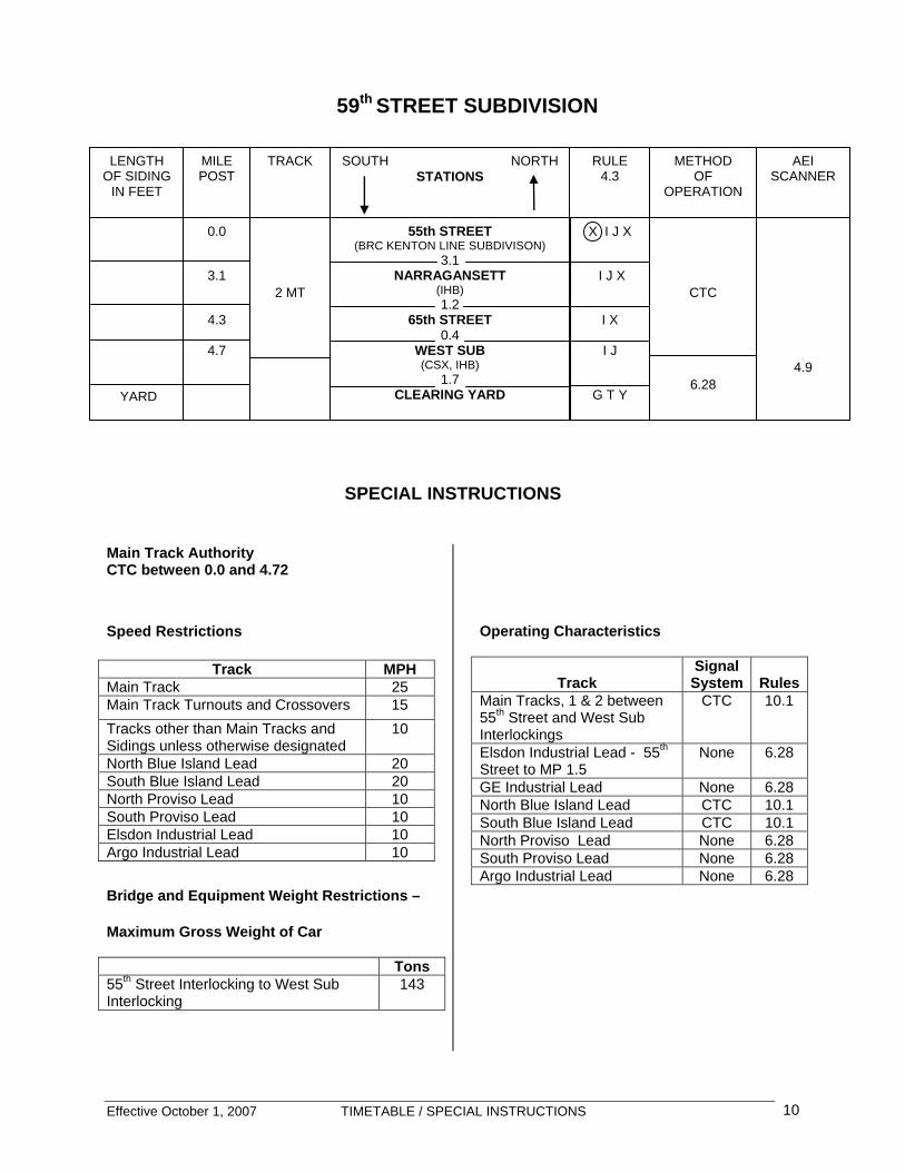
59TH STREET SUBDIVISION
SPECIAL INSTRUCTIONS
Main Track Authority CTC between 0.0 and 4.72 Speed Restrictions
Track MPH Main Track 25 Main Track Turnouts and Crossovers 15 Tracks other than Main Tracks and Sidings unless otherwise designated
10
North Blue Island Lead 20 South Blue Island Lead 20 North Proviso Lead 10 South Proviso Lead 10 Elsdon Industrial Lead 10 Argo Industrial Lead 10
Bridge and Equipment Weight Restrictions – Maximum Gross Weight of Car
Tons 55th Street Interlocking to West Sub Interlocking
143
Operating Characteristics
Track
Signal System
Rules
Main Tracks, 1 & 2 between 55th Street and West Sub Interlockings
CTC 10.1
Elsdon Industrial Lead - 55th Street to MP 1.5
None 6.28
GE Industrial Lead None 6.28 North Blue Island Lead CTC 10.1 South Blue Island Lead CTC 10.1 North Proviso Lead None 6.28 South Proviso Lead None 6.28 Argo Industrial Lead None 6.28
LENGTH OF SIDING
IN FEET
MILE POST
TRACK SOUTH NORTH STATIONS
RULE 4.3
METHOD OF
OPERATION
AEI SCANNER
55th STREET(BRC KENTON LINE SUBDIVISON)
3.1 NARRAGANSETT
(IHB) 1.2
65th STREET 0.4
WEST SUB (CSX, IHB)
1.7 CLEARING YARD
0.0
3.1
4.3
4.7
YARD
2 MT
X I J X
I J X
I X
I J
G T Y
CTC
6.28
4.9
59th STREET SUBDIVISION

Effective October 1, 2007 TIMETABLE / SPECIAL INSTRUCTIONS 11
911 Crossings - Emergency Communication The following street crossings have been identified as critical routes for delivery of emergency services to the City of Chicago. When trains are stopped or anticipated to be obstructing any of these crossings for more than ten (10) minutes, train crew must notify the train dispatcher immediately.
Upon receiving such notification, the train dispatcher will contact the City of Chicago Office of Emergency Communications and notify the Manager of Train Operations. A crew member must notify the train dispatcher when the train is clear of the crossing.
Subdivision Crossing Location 59th Street 5400 W. Central Avenue 59th Street 5600 W. 55th Street 59th Street 5932 S. Narragansett 59th Street 7200 W. 63rd Street
Radio Frequencies
Location AAR Frequency
BRC Frequency Contact Number
North Dispatcher - Kenton Line Subdivision Cragin to
and including 55th Street Interlocking. Includes 22nd Street Yard, 59th Street Subdivision, Elsdon Industrial Lead, Argo Industrial Lead, and West Sub to IHB connections at Argo and 71st Street.
39 - 39
Channel 4
Phone: (708) 496-4104
(708) 496-4105 Fax: (708) 496-4108
Special Conditions
63rd Street • Trains holding at 63rd Street must be
stopped a minimum of 200 feet north of crossing, if train length permits clearing of Narragansett street crossing.
Elsdon Industrial Lead
• BRC trackage extends between 55th St. Interlocking and MP 1.5.
• BRC Dispatcher must be contacted to obtain authority to occupy the Elsdon Industrial Lead.
• BRC Dispatcher must be contacted when clear of the Elsdon Industrial Lead.
• Movements towards BNSF Corwith Yard governed by GCOR 6.28. BNSF Corwith Yardmaster must be contacted via radio (AAR 36-36) for authority to enter trackage.
• Movement towards the CN Elsdon Industrial Track is governed by CN USOR 520 “Movement on other than
Main Track” (same as GCOR 6.28). CN Train Dispatcher #4 must be contacted via radio (AAR 28-28) for authority to enter trackage.
• Movement towards the NS 49th Street Line on No. 2 and No. 3 Industrial Tracks is governed by the Ashland Avenue Yardmaster via radio (AAR 64-64) for authority to enter trackage.
Argo Industrial Lead
• BRC Dispatcher must be contacted to obtain authority to occupy the Argo Industrial Lead.
• Cars will be handled with train line air hoses coupled and train line air cut in. Movement without air is prohibited on the Argo Industrial Lead.
CLEARING YARD SPECIAL INSTRUCTIONS
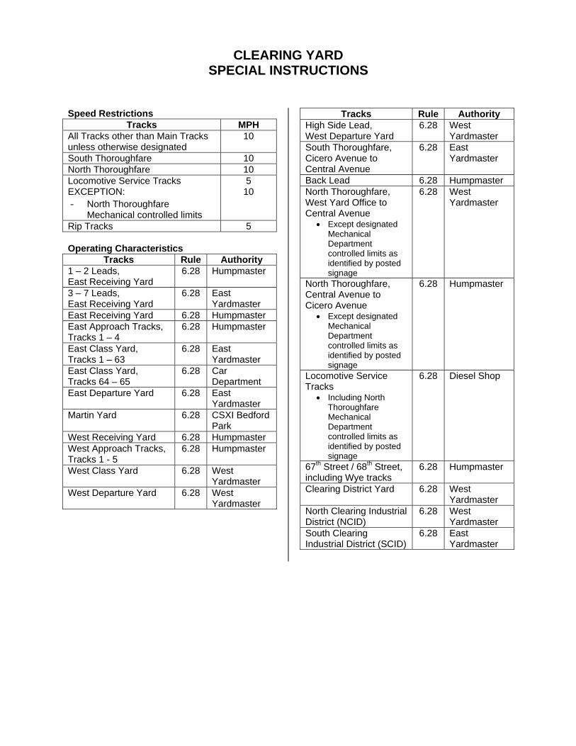
Speed Restrictions Tracks MPH
All Tracks other than Main Tracks unless otherwise designated
10
South Thoroughfare 10 North Thoroughfare 10 Locomotive Service Tracks EXCEPTION: - North Thoroughfare
Mechanical controlled limits
5 10
Rip Tracks 5 Operating Characteristics
Tracks Rule Authority 1 – 2 Leads, East Receiving Yard
6.28 Humpmaster
3 – 7 Leads, East Receiving Yard
6.28 East Yardmaster
East Receiving Yard 6.28 Humpmaster East Approach Tracks, Tracks 1 – 4
6.28 Humpmaster
East Class Yard, Tracks 1 – 63
6.28 East Yardmaster
East Class Yard, Tracks 64 – 65
6.28 Car Department
East Departure Yard 6.28 East Yardmaster
Martin Yard 6.28 CSXI Bedford Park
West Receiving Yard 6.28 Humpmaster West Approach Tracks, Tracks 1 - 5
6.28 Humpmaster
West Class Yard 6.28 West Yardmaster
West Departure Yard 6.28 West Yardmaster
Tracks Rule Authority High Side Lead, West Departure Yard
6.28 West Yardmaster
South Thoroughfare, Cicero Avenue to Central Avenue
6.28 East Yardmaster
Back Lead 6.28 Humpmaster North Thoroughfare, West Yard Office to Central Avenue
• Except designated Mechanical Department controlled limits as identified by posted signage
6.28 West Yardmaster
North Thoroughfare, Central Avenue to Cicero Avenue
• Except designated Mechanical Department controlled limits as identified by posted signage
6.28 Humpmaster
Locomotive Service Tracks
• Including North Thoroughfare Mechanical Department controlled limits as identified by posted signage
6.28 Diesel Shop
67th Street / 68th Street, including Wye tracks
6.28 Humpmaster
Clearing District Yard 6.28 West Yardmaster
North Clearing Industrial District (NCID)
6.28 West Yardmaster
South Clearing Industrial District (SCID)
6.28 East Yardmaster

Radio Frequencies Location AAR BRC Contact Number
North Dispatcher Kenton Line Subdivision, Cragin to and including 55th Street Interlocking. • Includes 22nd Street Yard, Elsdon
Industrial Lead, Argo Industrial Lead, and West Sub to IHB connections at Argo and 71st Street.
39 - 39
Channel 4
Phone: (708) 496-4104 (708) 496-4105 Fax: (708) 496-4108
South Dispatcher Kenton Line Subdivision, not including 55th St. interlocking to end of track at South Chicago
26 - 26
Channel 2
Phone: (708) 496-4101 (708) 496-4103 Fax: (708) 496-4045
Humpmaster 1 – 2 Leads, East Receiving Yard East Receiving Yard East Approach Tracks, Tracks 1 – 4 West Receiving Yard West Approach Tracks, Tracks 1 - 5 South Thoroughfare, Central Ave. to 6-xover Back Lead West Leg & East Leg of South Thoroughfare Wye to Hump Subway North Thoroughfare, Central Ave. to Cicero Ave
• Excluding Mechanical Department controlled limits
67th Street / 68th Street, including Wye tracks
57 – 57
Channel 1
Phone: (708) 496-4053
East Yardmaster 3 – 7 Leads, East Receiving Yard East Class Yard, Tracks 1 – 63 East Departure Yard South Thoroughfare, Cicero Ave to Central Ave. South Clearing Industrial District (SCID)
89 – 89
Channel 6
Phone: (708) 496-4128
West Yardmaster West Class Yard West Departure Yard Cabbage Patch Lead, West Departure Yard High Side Lead, West Departure Yard North Thoroughfare, West Yard Office to Central Ave
• Excluding Mechanical Department controlled limits
Clearing District Yard North Clearing Industrial District (NCID)
18 – 18
Channel 3
Phone: (708) 496-4130
Diesel Shop Locomotive Service Tracks
• Including North Thoroughfare Mechanical Department controlled limits
Hump Subway to West of 412 Pocket
79 – 79
Channel 5
Phone: (708) 496-4067
Car Department East Class Tracks 64 and 65
89 - 89
Channel 6
Phone: (708) 496-4091
Special Conditions
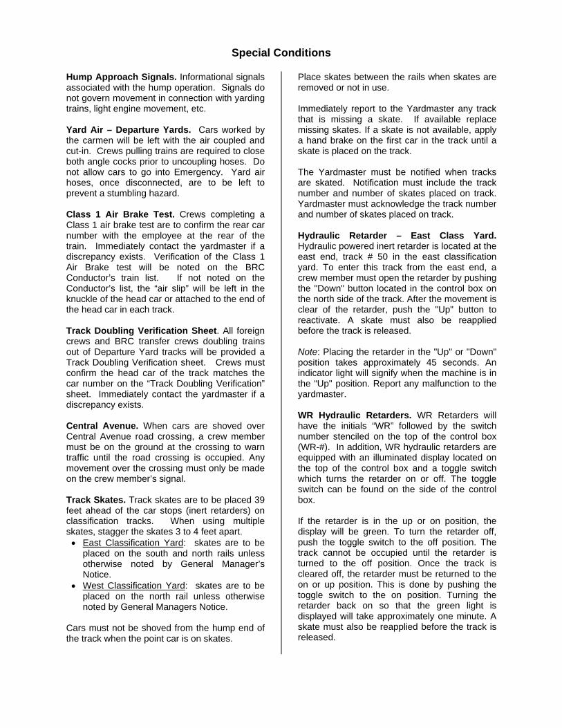
Hump Approach Signals. Informational signals associated with the hump operation. Signals do not govern movement in connection with yarding trains, light engine movement, etc. Yard Air – Departure Yards. Cars worked by the carmen will be left with the air coupled and cut-in. Crews pulling trains are required to close both angle cocks prior to uncoupling hoses. Do not allow cars to go into Emergency. Yard air hoses, once disconnected, are to be left to prevent a stumbling hazard. Class 1 Air Brake Test. Crews completing a Class 1 air brake test are to confirm the rear car number with the employee at the rear of the train. Immediately contact the yardmaster if a discrepancy exists. Verification of the Class 1 Air Brake test will be noted on the BRC Conductor’s train list. If not noted on the Conductor’s list, the “air slip” will be left in the knuckle of the head car or attached to the end of the head car in each track. Track Doubling Verification Sheet. All foreign crews and BRC transfer crews doubling trains out of Departure Yard tracks will be provided a Track Doubling Verification sheet. Crews must confirm the head car of the track matches the car number on the “Track Doubling Verification” sheet. Immediately contact the yardmaster if a discrepancy exists. Central Avenue. When cars are shoved over Central Avenue road crossing, a crew member must be on the ground at the crossing to warn traffic until the road crossing is occupied. Any movement over the crossing must only be made on the crew member’s signal. Track Skates. Track skates are to be placed 39 feet ahead of the car stops (inert retarders) on classification tracks. When using multiple skates, stagger the skates 3 to 4 feet apart. • East Classification Yard: skates are to be
placed on the south and north rails unless otherwise noted by General Manager’s Notice.
• West Classification Yard: skates are to be placed on the north rail unless otherwise noted by General Managers Notice.
Cars must not be shoved from the hump end of the track when the point car is on skates.
Place skates between the rails when skates are removed or not in use. Immediately report to the Yardmaster any track that is missing a skate. If available replace missing skates. If a skate is not available, apply a hand brake on the first car in the track until a skate is placed on the track. The Yardmaster must be notified when tracks are skated. Notification must include the track number and number of skates placed on track. Yardmaster must acknowledge the track number and number of skates placed on track. Hydraulic Retarder – East Class Yard. Hydraulic powered inert retarder is located at the east end, track # 50 in the east classification yard. To enter this track from the east end, a crew member must open the retarder by pushing the "Down" button located in the control box on the north side of the track. After the movement is clear of the retarder, push the "Up" button to reactivate. A skate must also be reapplied before the track is released. Note: Placing the retarder in the "Up" or "Down" position takes approximately 45 seconds. An indicator light will signify when the machine is in the “Up" position. Report any malfunction to the yardmaster. WR Hydraulic Retarders. WR Retarders will have the initials “WR” followed by the switch number stenciled on the top of the control box (WR-#). In addition, WR hydraulic retarders are equipped with an illuminated display located on the top of the control box and a toggle switch which turns the retarder on or off. The toggle switch can be found on the side of the control box. If the retarder is in the up or on position, the display will be green. To turn the retarder off, push the toggle switch to the off position. The track cannot be occupied until the retarder is turned to the off position. Once the track is cleared off, the retarder must be returned to the on or up position. This is done by pushing the toggle switch to the on position. Turning the retarder back on so that the green light is displayed will take approximately one minute. A skate must also be reapplied before the track is released.
Effective October 1, 2007 TIMETABLE / SPECIAL INSTRUCTIONS 15
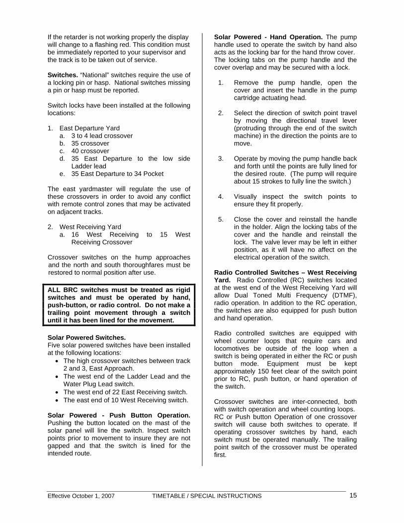
If the retarder is not working properly the display will change to a flashing red. This condition must be immediately reported to your supervisor and the track is to be taken out of service. Switches. “National” switches require the use of a locking pin or hasp. National switches missing a pin or hasp must be reported. Switch locks have been installed at the following locations: 1. East Departure Yard
a. 3 to 4 lead crossover b. 35 crossover c. 40 crossover d. 35 East Departure to the low side
Ladder lead e. 35 East Departure to 34 Pocket
The east yardmaster will regulate the use of these crossovers in order to avoid any conflict with remote control zones that may be activated on adjacent tracks.
2. West Receiving Yard
a. 16 West Receiving to 15 West Receiving Crossover
Crossover switches on the hump approaches and the north and south thoroughfares must be restored to normal position after use. ALL BRC switches must be treated as rigid switches and must be operated by hand, push-button, or radio control. Do not make a trailing point movement through a switch until it has been lined for the movement. Solar Powered Switches. Five solar powered switches have been installed at the following locations:
• The high crossover switches between track 2 and 3, East Approach.
• The west end of the Ladder Lead and the Water Plug Lead switch.
• The west end of 22 East Receiving switch. • The east end of 10 West Receiving switch.
Solar Powered - Push Button Operation. Pushing the button located on the mast of the solar panel will line the switch. Inspect switch points prior to movement to insure they are not gapped and that the switch is lined for the intended route.
Solar Powered - Hand Operation. The pump handle used to operate the switch by hand also acts as the locking bar for the hand throw cover. The locking tabs on the pump handle and the cover overlap and may be secured with a lock.
1. Remove the pump handle, open the cover and insert the handle in the pump cartridge actuating head.
2. Select the direction of switch point travel
by moving the directional travel lever (protruding through the end of the switch machine) in the direction the points are to move.
3. Operate by moving the pump handle back
and forth until the points are fully lined for the desired route. (The pump will require about 15 strokes to fully line the switch.)
4. Visually inspect the switch points to
ensure they fit properly. 5. Close the cover and reinstall the handle
in the holder. Align the locking tabs of the cover and the handle and reinstall the lock. The valve lever may be left in either position, as it will have no affect on the electrical operation of the switch.
Radio Controlled Switches – West Receiving Yard. Radio Controlled (RC) switches located at the west end of the West Receiving Yard will allow Dual Toned Multi Frequency (DTMF), radio operation. In addition to the RC operation, the switches are also equipped for push button and hand operation. Radio controlled switches are equipped with wheel counter loops that require cars and locomotives be outside of the loop when a switch is being operated in either the RC or push button mode. Equipment must be kept approximately 150 feet clear of the switch point prior to RC, push button, or hand operation of the switch. Crossover switches are inter-connected, both with switch operation and wheel counting loops. RC or Push button Operation of one crossover switch will cause both switches to operate. If operating crossover switches by hand, each switch must be operated manually. The trailing point switch of the crossover must be operated first.

Effective October 1, 2007 TIMETABLE / SPECIAL INSTRUCTIONS 16
Switch operations that "Fault" will have to be inspected for obstruction or in winter operations, cleaned free of snow and/or ice. When a RC switch broadcasts "switch # out of correspondence", check the points of all switches associated with that switch number. The Yardmaster must be contacted prior to occupying or fouling the Ladder Lead or Back Lead unless authority has been previously authorized Switches are equipped with mast-mounted Indicator Lights. Aspects indicate the following switch position: • Green Normal • White Route Activated, switch included
as part of route • Amber Reverse
Switch No.
Track
Switch No.
Track
001 6 Crossover
009 9 West Receiving
002 2 West Receiving
010 10 West Receiving
003 3 West Receiving
011 11 West Receiving
004 4 West Receiving
012 12 West Receiving
005 5 West Receiving
013 13 West Receiving
006 6 West Receiving
014 14 West Receiving
007 7 West Receiving
015 15 West Receiving
008 8 West Receiving
016 16 West Receiving
Radio Controlled Switches - Push Button Operation. The push button is located inside a small protective cover and secured with a locking hasp and cover. The hasp must be secured with a lock or hook when push button is not in use.
1. Lift the cover from the hasp, and push the button located under the cover plate.
2. The switch will line opposite of the current route.
3. Replace the lock or hook, if available, and secure.
4. Visually inspect the switch points to ensure they fit properly.
Radio Controlled Switches - Hand Operation. The pump handle used to operate the switch by
hand also acts as the locking bar for the hand throw cover. The locking tabs on the pump handle and the cover overlap and may be secured with a lock.
1. Remove the pump handle, open the cover and insert the handle in the pump cartridge actuating head.
2. Select the direction of switch point travel by moving the directional travel lever (protruding through the end of the switch machine) in the direction the points are to move.
3. Operate by moving the pump handle back and forth until the points are fully lined for the desired route. (The pump will require about 15 strokes to fully line the switch.)
4. Visually inspect the switch points to ensure they fit properly.
5. Close the cover and reinstall the handle in the holder. Align the locking tabs of the cover and the handle and reinstall the lock. The valve lever may be left in either position, as it will have no affect on the electrical operation of the switch.
Radio Controlled Switches - Radio Control Operation. Switches equipped with radio control have been designated to use the BRC Hump Channel 1/AAR Frequency 57-57. Each switch, or interconnected crossover, is designated by a switch number. The radio keypad is used to "call" the switch and command a position. The first keystroke required for (RC) operation of these switches will be the # key. This key "wakes" the switch machine and prepares it for an actuation code transmission. Radio Controlled Switches - Individual Switch Operation. A series of six entries via the radio key pad will line the switch for movement. Enter the # key followed by a switch number ranging from 001 to 016, followed again by the # key and the “1” for reverse or the “2” for normal position. The position of a switch may be determined by using the “query” command. A voice message will announce the switch position. If a DTMF code is entered that is not recognized by the system, the system will respond with “Bad Command”.
Effective October 1, 2007 TIMETABLE / SPECIAL INSTRUCTIONS 17
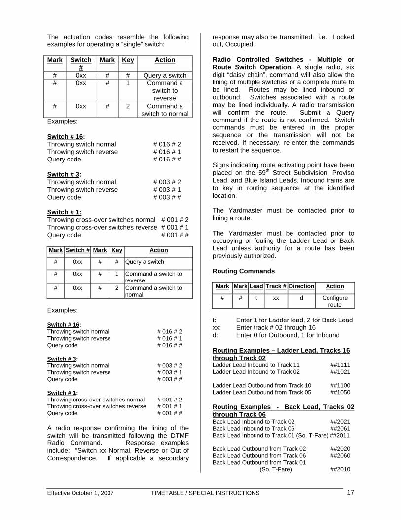
The actuation codes resemble the following examples for operating a “single” switch: Mark Switch
# Mark Key Action
# 0xx # # Query a switch # 0xx # 1 Command a
switch to reverse
# 0xx # 2 Command a switch to normal
Examples: Switch # 16: Throwing switch normal # 016 # 2 Throwing switch reverse # 016 # 1 Query code # 016 # # Switch # 3: Throwing switch normal # 003 # 2 Throwing switch reverse # 003 # 1 Query code # 003 # # Switch # 1: Throwing cross-over switches normal # 001 # 2 Throwing cross-over switches reverse # 001 # 1 Query code # 001 # # Mark Switch # Mark Key Action
# 0xx # # Query a switch
# 0xx # 1 Command a switch to reverse
# 0xx # 2 Command a switch to normal
Examples: Switch # 16: Throwing switch normal # 016 # 2 Throwing switch reverse # 016 # 1 Query code # 016 # # Switch # 3: Throwing switch normal # 003 # 2 Throwing switch reverse # 003 # 1 Query code # 003 # # Switch # 1: Throwing cross-over switches normal # 001 # 2 Throwing cross-over switches reverse # 001 # 1 Query code # 001 # # A radio response confirming the lining of the switch will be transmitted following the DTMF Radio Command. Response examples include: “Switch xx Normal, Reverse or Out of Correspondence. If applicable a secondary
response may also be transmitted. i.e.: Locked out, Occupied. Radio Controlled Switches - Multiple or Route Switch Operation. A single radio, six digit “daisy chain”, command will also allow the lining of multiple switches or a complete route to be lined. Routes may be lined inbound or outbound. Switches associated with a route may be lined individually. A radio transmission will confirm the route. Submit a Query command if the route is not confirmed. Switch commands must be entered in the proper sequence or the transmission will not be received. If necessary, re-enter the commands to restart the sequence. Signs indicating route activating point have been placed on the 59th Street Subdivision, Proviso Lead, and Blue Island Leads. Inbound trains are to key in routing sequence at the identified location. The Yardmaster must be contacted prior to lining a route. The Yardmaster must be contacted prior to occupying or fouling the Ladder Lead or Back Lead unless authority for a route has been previously authorized. Routing Commands Mark Mark Lead Track # Direction Action
# # t xx d Configure route
t: Enter 1 for Ladder lead, 2 for Back Lead xx: Enter track # 02 through 16 d: Enter 0 for Outbound, 1 for Inbound Routing Examples – Ladder Lead, Tracks 16 through Track 02 Ladder Lead Inbound to Track 11 ##1111 Ladder Lead Inbound to Track 02 ##1021 Ladder Lead Outbound from Track 10 ##1100 Ladder Lead Outbound from Track 05 ##1050 Routing Examples - Back Lead, Tracks 02 through Track 06 Back Lead Inbound to Track 02 ##2021 Back Lead Inbound to Track 06 ##2061 Back Lead Inbound to Track 01 (So. T-Fare) ##2011 Back Lead Outbound from Track 02 ##2020 Back Lead Outbound from Track 06 ##2060 Back Lead Outbound from Track 01
(So. T-Fare) ##2010
Effective October 1, 2007 TIMETABLE / SPECIAL INSTRUCTIONS 18
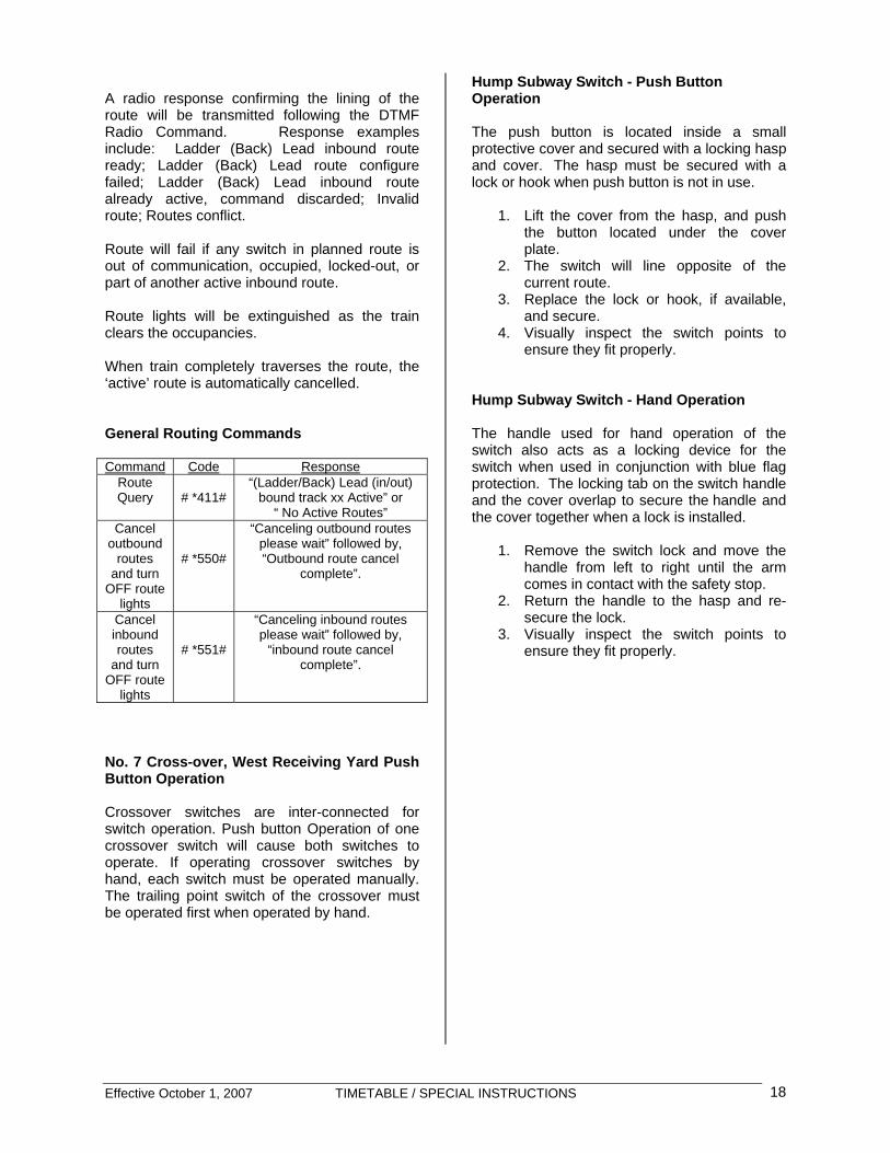
A radio response confirming the lining of the route will be transmitted following the DTMF Radio Command. Response examples include: Ladder (Back) Lead inbound route ready; Ladder (Back) Lead route configure failed; Ladder (Back) Lead inbound route already active, command discarded; Invalid route; Routes conflict. Route will fail if any switch in planned route is out of communication, occupied, locked-out, or part of another active inbound route. Route lights will be extinguished as the train clears the occupancies. When train completely traverses the route, the ‘active’ route is automatically cancelled. General Routing Commands Command Code Response
Route Query
# *411#
“(Ladder/Back) Lead (in/out) bound track xx Active” or
“ No Active Routes” Cancel
outbound routes
and turn OFF route
lights
# *550#
“Canceling outbound routes please wait” followed by, “Outbound route cancel
complete”.
Cancel inbound routes
and turn OFF route
lights
# *551#
“Canceling inbound routes please wait” followed by,
“inbound route cancel complete”.
No. 7 Cross-over, West Receiving Yard Push Button Operation Crossover switches are inter-connected for switch operation. Push button Operation of one crossover switch will cause both switches to operate. If operating crossover switches by hand, each switch must be operated manually. The trailing point switch of the crossover must be operated first when operated by hand.
Hump Subway Switch - Push Button Operation The push button is located inside a small protective cover and secured with a locking hasp and cover. The hasp must be secured with a lock or hook when push button is not in use.
1. Lift the cover from the hasp, and push the button located under the cover plate.
2. The switch will line opposite of the current route.
3. Replace the lock or hook, if available, and secure.
4. Visually inspect the switch points to ensure they fit properly.
Hump Subway Switch - Hand Operation The handle used for hand operation of the switch also acts as a locking device for the switch when used in conjunction with blue flag protection. The locking tab on the switch handle and the cover overlap to secure the handle and the cover together when a lock is installed.
1. Remove the switch lock and move the
handle from left to right until the arm comes in contact with the safety stop.
2. Return the handle to the hasp and re-secure the lock.
3. Visually inspect the switch points to ensure they fit properly.

Effective October 1, 2007 TIMETABLE / SPECIAL INSTRUCTIONS 19
Notes
Notes

Effective October 1, 2007 TIMETABLE / SPECIAL INSTRUCTIONS 20
Notes
Notes

Effective October 1, 2007 TIMETABLE / SPECIAL INSTRUCTIONS 21
The Belt Railway Company
of Chicago
SYSTEM
SPECIAL INSTRUCTIONS
Michael A. Paras General Manager Transportation
Effective October 1, 2007 TIMETABLE / SPECIAL INSTRUCTIONS 22
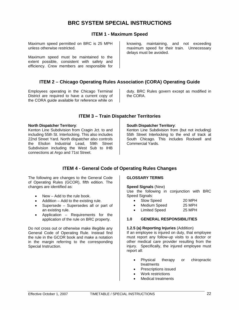
BRC SYSTEM SPECIAL INSTRUCTIONS
ITEM 1 - Maximum Speed Maximum speed permitted on BRC is 25 MPH unless otherwise restricted. Maximum speed must be maintained to the extent possible, consistent with safety and efficiency. Crew members are responsible for
knowing, maintaining, and not exceeding maximum speed for their train. Unnecessary delays must be avoided.
ITEM 2 – Chicago Operating Rules Association (CORA) Operating Guide Employees operating in the Chicago Terminal District are required to have a current copy of the CORA guide available for reference while on
duty. BRC Rules govern except as modified in the CORA.
ITEM 3 – Train Dispatcher Territories North Dispatcher Territory: Kenton Line Subdivision from Cragin Jct. to and including 55th St. Interlocking. This also includes 22nd Street Yard. North dispatcher also controls the Elsdon Industrial Lead, 59th Street Subdivision including the West Sub to IHB connections at Argo and 71st Street.
South Dispatcher Territory: Kenton Line Subdivision from (but not including) 55th Street Interlocking to the end of track at South Chicago. This includes Rockwell and Commercial Yards.
ITEM 4 - General Code of Operating Rules Changes The following are changes to the General Code of Operating Rules (GCOR), fifth edition. The changes are identified as:
• New – Add to the rule book. • Addition – Add to the existing rule. • Supersede – Supersedes all or part of
an existing rule. • Application – Requirements for the
application of the rule on BRC property.
Do not cross out or otherwise make illegible any General Code of Operating Rule. Instead find the rule in the GCOR book and make a notation in the margin referring to the corresponding Special Instruction.
GLOSSARY TERMS Speed Signals (New) Use the following in conjunction with BRC Speed Signals:
• Slow Speed 20 MPH • Medium Speed 25 MPH • Limited Speed 25 MPH
1.0 GENERAL RESPONSIBILITIES 1.2.5 (a) Reporting Injuries (Addition) If an employee is injured on duty, that employee must report any follow-up visits to a doctor or other medical care provider resulting from the injury. Specifically, the injured employee must report all:
• Physical therapy or chiropractic treatments
• Prescriptions issued • Work restrictions • Medical treatments
Effective October 1, 2007 TIMETABLE / SPECIAL INSTRUCTIONS 23
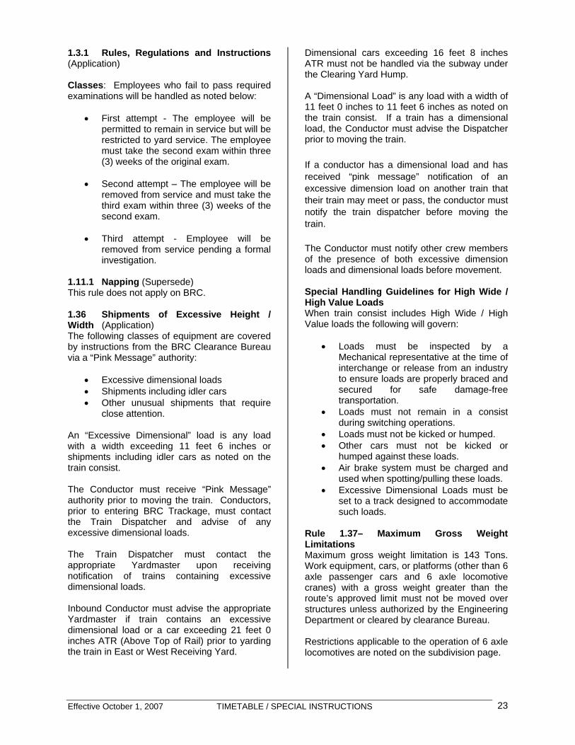
1.3.1 Rules, Regulations and Instructions (Application) Classes: Employees who fail to pass required examinations will be handled as noted below:
• First attempt - The employee will be permitted to remain in service but will be restricted to yard service. The employee must take the second exam within three (3) weeks of the original exam.
• Second attempt – The employee will be
removed from service and must take the third exam within three (3) weeks of the second exam.
• Third attempt - Employee will be
removed from service pending a formal investigation.
1.11.1 Napping (Supersede) This rule does not apply on BRC. 1.36 Shipments of Excessive Height / Width (Application) The following classes of equipment are covered by instructions from the BRC Clearance Bureau via a “Pink Message” authority:
• Excessive dimensional loads • Shipments including idler cars • Other unusual shipments that require
close attention.
An “Excessive Dimensional” load is any load with a width exceeding 11 feet 6 inches or shipments including idler cars as noted on the train consist. The Conductor must receive “Pink Message” authority prior to moving the train. Conductors, prior to entering BRC Trackage, must contact the Train Dispatcher and advise of any excessive dimensional loads. The Train Dispatcher must contact the appropriate Yardmaster upon receiving notification of trains containing excessive dimensional loads. Inbound Conductor must advise the appropriate Yardmaster if train contains an excessive dimensional load or a car exceeding 21 feet 0 inches ATR (Above Top of Rail) prior to yarding the train in East or West Receiving Yard.
Dimensional cars exceeding 16 feet 8 inches ATR must not be handled via the subway under the Clearing Yard Hump. A “Dimensional Load” is any load with a width of 11 feet 0 inches to 11 feet 6 inches as noted on the train consist. If a train has a dimensional load, the Conductor must advise the Dispatcher prior to moving the train. If a conductor has a dimensional load and has received “pink message” notification of an excessive dimension load on another train that their train may meet or pass, the conductor must notify the train dispatcher before moving the train. The Conductor must notify other crew members of the presence of both excessive dimension loads and dimensional loads before movement. Special Handling Guidelines for High Wide / High Value Loads When train consist includes High Wide / High Value loads the following will govern:
• Loads must be inspected by a Mechanical representative at the time of interchange or release from an industry to ensure loads are properly braced and secured for safe damage-free transportation.
• Loads must not remain in a consist during switching operations.
• Loads must not be kicked or humped. • Other cars must not be kicked or
humped against these loads. • Air brake system must be charged and
used when spotting/pulling these loads. • Excessive Dimensional Loads must be
set to a track designed to accommodate such loads.
Rule 1.37– Maximum Gross Weight Limitations Maximum gross weight limitation is 143 Tons. Work equipment, cars, or platforms (other than 6 axle passenger cars and 6 axle locomotive cranes) with a gross weight greater than the route’s approved limit must not be moved over structures unless authorized by the Engineering Department or cleared by clearance Bureau. Restrictions applicable to the operation of 6 axle locomotives are noted on the subdivision page.

Effective October 1, 2007 TIMETABLE / SPECIAL INSTRUCTIONS 24
1.48 Locomotive Shut Down (New) When it is known that locomotives will not be used for one hour or more, and the ambient temperature is not expected to fall below 40 degrees Fahrenheit, locomotives must be shut down except when authorized by local supervisors or train dispatcher.
• Leave one unit of multiple unit locomotives running to maintain air pressure when coupled to cars.
• It is not necessary to shut down DP (Distributed Power) units in a train unless instructed by the train dispatcher or local supervisors.
• Locomotives with a tag indicating “weak batteries” should not be shutdown until the condition is corrected.
• Locomotives equipped with an automatic start/stop system may be left running, however the switch must be properly positioned with the indicator light/message showing the system is enabled. If the auto start/stop system is not operable the unit is considered to be non-equipped. Remote control locomotives must be in the manual mode to have the system operable.
• Contact the train dispatcher, yardmaster, or local supervisor concerning the expected length of the delay or the expected temperature during the shutdown.
• Secure unattended equipment to prevent movement.
• Shut down diesel engine in compliance with current rules and/or instructions.
2.0 RAILROAD RADIO RULES 2.3 Repetition (Application) When a transmission has been repeated correctly, the acknowledgement must be "That is Correct". 3.0 STANDARD TIME 3.4 Time Change (New) At 0200 on the Second Sunday in March each year, Standard Time is advanced one hour to 0300. At 0200 on the First Sunday of November each year, Standard Time is set back one hour to 0100. Watches and Standard Clocks must be changed accordingly.
4.0 TIMETABLES 4.3 Timetable Characters (Application) G - General Orders, Notices, Bulletins, Standard Clock I - Manual Interlocking J - Junction T - Turntable or Wye X - Crossover X(2) - Multiple Crossovers X - Railroad Crossing at Grade Y - Yard YL - Yard Limits 5.0 SIGNALS AND THEIR USE 5.4 Flags for Temporary Track Conditions (Supersede) This rule does not apply on BRC. 5.5 Permanent Speed Signs (Supersede) This rule does not apply on BRC. 5.7 Torpedoes (Supersede) This rule does not apply on BRC. 5.8.1 Ringing Engine Bell (Addition) Add these bullet points to the rule:
• While moving within the locomotive servicing facility
• At all private road crossings within Clearing Yards
5.8.2 Sounding Whistles (Application) Ordinances prohibit the sounding of engine whistles within the limits of the City of Chicago except when necessary to prevent injury or warn employees on or about the track or the public.
• EXCEPTION: whistle must be sounded for Columbus Avenue (Southwest Hwy) and Archer Avenue.
6.0 MOVEMENT OF TRAINS AND ENGINES 6.2.2 Daily Operating Bulletin (DOB) (New) Daily Operating Bulletin will be issued by the dispatcher to protect temporary track conditions or flagman assignments for the next 24 hour period. DOB will be in effect at time of issue.
Effective October 1, 2007 TIMETABLE / SPECIAL INSTRUCTIONS 25
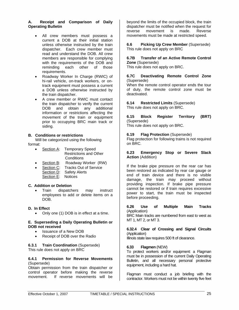
A. Receipt and Comparison of Daily Operating Bulletin
• All crew members must possess a
current a DOB at their initial station unless otherwise instructed by the train dispatcher. Each crew member must read and understand the DOB. All crew members are responsible for complying with the requirements of the DOB and reminding each other of those requirements.
• Roadway Worker In Charge (RWIC) of hi-rail vehicle, on-track workers, or on-track equipment must possess a current a DOB unless otherwise instructed by the train dispatcher.
• A crew member or RWIC must contact the train dispatcher to verify the current DOB and obtain any additional information or restrictions affecting the movement of the train or equipment prior to occupying BRC main track or siding.
B. Conditions or restrictions
Will be categorized using the following format:
• Section A: Temporary Speed Restrictions and Other
Conditions • Section B: Roadway Worker (RW) • Section C: Tracks Out of Service
Section D: Safety Alerts Section E: Notices
C. Addition or Deletion
• Train dispatchers may instruct employees to add or delete items on a DOB.
D. In Effect • Only one (1) DOB is in effect at a time.
E. Superseding a Daily Operating Bulletin or DOB not received
• Issuance of a New DOB • Receipt of DOB over the Radio
6.3.1 Train Coordination (Supersede) This rule does not apply on BRC 6.4.1 Permission for Reverse Movements (Supersede) Obtain permission from the train dispatcher or control operator before making the reverse movement. If reverse movements will be
beyond the limits of the occupied block, the train dispatcher must be notified when the request for reverse movement is made. Reverse movements must be made at restricted speed. 6.6 Picking Up Crew Member (Supersede) This rule does not apply on BRC 6.7B Transfer of an Active Remote Control Zone (Supersede) This rule does not apply on BRC. 6.7C Deactivating Remote Control Zone (Supersede) When the remote control operator ends the tour of duty, the remote control zone must be deactivated. 6.14 Restricted Limits (Supersede) This rule does not apply on BRC. 6.15 Block Register Territory (BRT) (Supersede) This rule does not apply on BRC. 6.19 Flag Protection (Supersede) Flag protection for following trains is not required on BRC. 6.23 Emergency Stop or Severe Slack Action (Addition) If the brake pipe pressure on the rear car has been restored as indicated by rear car gauge or end of train device and there is no visible damage, the train may proceed without providing inspection. If brake pipe pressure cannot be restored or if train requires excessive power to start, the train must be inspected before proceeding. 6.26 Use of Multiple Main Tracks (Application) BRC Main tracks are numbered from east to west as MT 1, MT 2, or MT 3. 6.32.4 Clear of Crossing and Signal Circuits (Application) Illinois state law requires 500 ft of clearance. 6.33 Flagmen (NEW) To protect workers and/or equipment: a Flagman must be in possession of the current Daily Operating Bulletin, and all necessary personal protective equipment, including a hard hat. Flagman must conduct a job briefing with the contractor. Workers must not be within twenty five feet

Effective October 1, 2007 TIMETABLE / SPECIAL INSTRUCTIONS 26
of controlled track(s) without a flagman. Authority must be obtained from the Train Dispatcher prior to fouling tracks On non-controlled tracks protection must be afforded by the flagman. When necessary, coordinate protection with the Yardmaster or other employee responsible for directing train movement. 7.0 SWITCHING 7.4.1 Safety Stop (New) Stop the movement at least 50 feet but not more than 250 feet before coupling to equipment. Make certain that:
• Coupler is aligned • At least one of the knuckles is open • Light engines must stop 50 feet before
coupling to equipment • Remote control light engines must stop 50
feet before coupling to equipment and then couple at “Couple Speed”
• Employees must not ride cars to coupling
7.6 Securing Cars or Engines (Addition) Add the following sentence to the end of the first paragraph: Anything other than approved steel wheel chocks is prohibited. The following tonnage chart will be used in connection with the application of this rule.
Tons GRADE 0 0.25 0.50 0.75 1.00 1.25+<1000 2 2 2 2 3 3 1000+ 2 3 3 3 5 6 2000+ 2 3 5 5 6 8 3000+ 3 5 5 7 8 10 4000+ 4 5 5 8 10 13 5000+ 5 6 7 9 12 15 6000+ 5 7 8 11 14 18 7000+ 5 7 9 13 16 21 8000+ 5 8 10 14 18 23 9000+ 5 9 12 15 20 25 10000+ 6 10 13 17 22 28 11000+ 6 11 15 18 24 30 12000+ 7 14 16 20 26 33 13000+ 8 15 17 22 28 35 14000+ 8 15 20 23 30 38
Location
Grade Handbrake
Requirement Clearing Receiving Tracks
None
Clearing Departure Tracks
3 Handbrakes
Clearing Approach Tracks
10 handbrakes + 10% air
Argo Industrial Lead
1.40 % Refer to chart
22nd Street North end
1.20 % Refer to chart
22nd Street South end
0.50 % Refer to chart
C & A Siding 0.25 % Refer to chart Cookie Yard 0.25 % Refer to chart Rockwell Yard 0.25 % Refer to chart Third Rail 0.40 % Refer to chart Commercial Avenue
0.30 % Refer to chart
So Chicago District Yard
0 % Refer to chart
KCBX 3 handbrakes
7.6.1 Unattended Locomotives (new)
o CLEARING YARD: Minimum of one hand brake applied.
o OTHER LOCATIONS: All locomotives
must have the handbrake applied.

Effective October 1, 2007 TIMETABLE / SPECIAL INSTRUCTIONS 27
7.7 Kicking or Dropping) Cars (Application) Dropping cars on the BRC is prohibited.
Kicking cars is prohibited in the following locations:
o Classification Yards o West end of track 35 to 47 East Departure
Yard o West end of Scrap Dock tracks o West end of 1 Main to 4 Main in the
Clearing District Yard 7.10 Gates and Doorways (Addition) Add the following sentence to the end of the rule: Do not ride on the side of a car, engine or other equipment when moving through gates, doorways or similar openings.
7.11 Charging Necessary Air Brakes (Application) A minimum of 10 per cent of the cars being handled must have air brakes charged when:
• Pulling cars from the classification yards (this does not apply when trimming or reclassifying from the hump end of the classification yards).
• Shoving cars up the hump approaches. 8.0 SWITCHES 8.2 Position of Switches (Addition) Add the Following: ALL BRC switches must be treated as rigid switches and must be operated by hand, push-button, or radio control. Do not make a trailing point movement through a switch until it has been lined for the movement. 9.0 BLOCK SIGNAL RULES
ITEM 5 – Remote Control Zones Only remote control crews may activate a remote control zone. The zone will be activated by notifying the yardmaster who will record this information in the appropriate log. The remote control crew must advise the yardmaster when the zone is deactivated. The yardmaster must record each time the zone is activated or deactivated. Some remote control zones are equipped with signs that lie between the rails while the zone is deactivated. After activating a zone equipped with a sign the remote control crew must put the sign up. The crew will also be responsible for taking the sign down when the zone is deactivated. If a crew neglects to take the sign down the yardmaster may instruct another employee to visually inspect the zone. If the zone is clear the yardmaster may instruct that employee to take the sign down. Some remote control zones are equipped with Pullback Stopping Protection (PSP). On the initial movement into PSP limits the remote control operator must monitor the talker messages and verify PSP is functioning as
intended. BRC hump engines are not equipped with PSP. General Code of Operating Rules govern Remote Control Movements (6.5.1) and Remote Control Zones (6.7). Remote control zones are designated as follows: 6 Lead • Located at the east end of the East
Departure Yard. • Begins at the 40 crossover switch and ends
approximately 240 feet west of the 6 lead signal at the East End Switches Interlocking.
• Contact: East Yardmaster. • A sign designates the end of the zone. • Before activating this zone both ends of the
35 crossover must be lined and locked for straight movement. The switch locks must be removed when the zone is deactivated.
• Equipped with PSP.

Effective October 1, 2007 TIMETABLE / SPECIAL INSTRUCTIONS 28
5 Lead • Located at east end of East Departure
Yard. • Begins approximately 120 feet east of the
35 crossover switch on 5 lead and ends approximately 240 feet west of the 5 lead signal at the East End Switches Interlocking.
• Contact: East Yardmaster. • Signs designate the beginning and end of
the zone. • Before activating this zone both ends of
the 35 crossover must be lined and locked for straight movement. The switch locks must be removed when the zone is deactivated.
• Equipped with PSP. 4 Lead • Located at the east end of the East
Departure Yard. • Begins approximately 60 feet east of the
4 lead switch and ends approximately 240 feet west of the 4 lead signal at the East End Switches Interlocking.
• Contact: East Yardmaster. • Signs designate the beginning and end of
the zone. • Before activating this zone both ends of
3 lead/4 lead crossover must be lined and locked for straight movement. The switch locks must be removed when the zone is deactivated.
• Equipped with PSP. 3 Lead • Located at the east end of the East
Departure Yard. • Begins approximately 60 feet east of the
3 lead switch and ends approximately 240 feet west of the 3 lead signal at the East End Switches Interlocking.
• Contact: East Yardmaster. • Signs designate the beginning and end of
the zone. • Before activating this zone both ends of
3 lead/4 lead crossover must be lined and locked for straight movement. The switch locks must be removed when the zone is deactivated.
• Equipped with PSP.
2 Lead • Located at the east end of the East
Receiving Yard. • Begins at the east end of the 17 crossover
switch and ends approximately 240 feet west of the 2 lead signal at the East End Switches Interlocking.
• Contact: Hump Yardmaster. • Signs designate the beginning and end of
the zone. There are also signs at 23 crossover (which is the switch from 2 lead to the East Departure Yard) and at 12 crossover which designates entrances to the zone. Due to close track clearance, a sign designating the entrance to this zone is not posted at the 6 crossover.
• Before activating this zone the east end of 17 crossover must be lined and locked for the movement and both ends of 12, 23, and 6 crossovers must be lined and locked for straight movement. The switch locks must be removed when the zone is deactivated.
• Equipped with PSP. South C.I.D. North Lead • Located on the north lead of the South
C.I.D. • Begins just beyond the divide switch to the
north and south leads of the South C.I.D. • Contact: East Yardmaster. • A sign designates the beginning of the
zone. • Not equipped with PSP.
South C.I.D. South Lead • Located on the south lead of the South
C.I.D. • Begins just beyond the divide switch to the
north and south leads of the South C.I.D. • Contact: East Yardmaster. • A sign designates the beginning of the
zone. • Not equipped with PSP.
Effective October 1, 2007 TIMETABLE / SPECIAL INSTRUCTIONS 29
Cabbage Patch Lead • Located at the west end of the West
Departure Yard. • Begins immediately west of the cabbage
patch lead switch coming out of the low side of the west departure yard and ends approximately 280 feet east of the high side/cabbage patch divide switch.
• Contact: West Yardmaster. • Signs designate the beginning and end of
the zone. • Equipped with PSP.
High Side Lead
• Located at west end of the West Departure Yard.
• Begins approximately 75 feet west of the fire road on the high side lead and ends approximately 285 feet east of the high side/cabbage patch divide switch.
• Contact: West Yardmaster. • Signs designate the beginning and end of
the zone. • Equipped with PSP.
North C.I.D. - East • Located on the North C.I.D. between
Central Avenue and the Nalco switch. • Begins just west of Central Avenue on the
North CID and extends to approximately 900 feet east of the Nalco switch.
• Contact: West Yardmaster. • Signs are not posted. • There is a derail between the two zones on
the North C.I.D. This derail need not be applied when one crew activates both zones or only the east zone is activated.
• Not equipped with PSP. North C.I.D - West • Located on the North C.I.D. between the
Nalco switch and the old Harlem crossing. • Begins approximately 600 feet east of the
Nalco switch and extends westward to approximately 60 feet east of the old Harlem crossing.
• Contact: West Yardmaster. • Signs are not posted. • There is a derail between the two zones on
the North C.I.D. that must be applied when the west zone is activated.
• Not equipped with PSP.
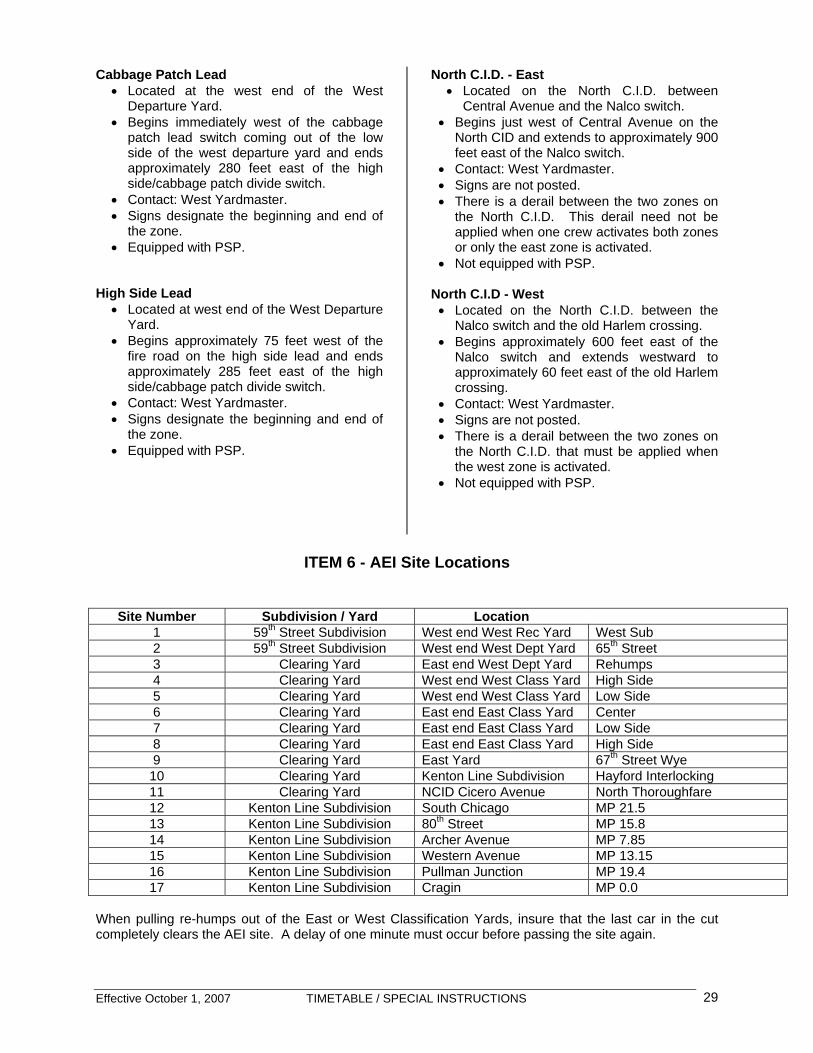
ITEM 6 - AEI Site Locations
Site Number Subdivision / Yard Location 1 59th Street Subdivision West end West Rec Yard West Sub 2 59th Street Subdivision West end West Dept Yard 65th Street 3 Clearing Yard East end West Dept Yard Rehumps 4 Clearing Yard West end West Class Yard High Side 5 Clearing Yard West end West Class Yard Low Side 6 Clearing Yard East end East Class Yard Center 7 Clearing Yard East end East Class Yard Low Side 8 Clearing Yard East end East Class Yard High Side 9 Clearing Yard East Yard 67th Street Wye 10 Clearing Yard Kenton Line Subdivision Hayford Interlocking 11 Clearing Yard NCID Cicero Avenue North Thoroughfare 12 Kenton Line Subdivision South Chicago MP 21.5 13 Kenton Line Subdivision 80th Street MP 15.8 14 Kenton Line Subdivision Archer Avenue MP 7.85 15 Kenton Line Subdivision Western Avenue MP 13.15 16 Kenton Line Subdivision Pullman Junction MP 19.4 17 Kenton Line Subdivision Cragin MP 0.0
When pulling re-humps out of the East or West Classification Yards, insure that the last car in the cut completely clears the AEI site. A delay of one minute must occur before passing the site again.

ITEM 7 - Cold Weather Train Length Restrictions
The following train length restrictions govern outbound train movements originating at BRC Clearing Yard:
Temperature (F) Length 30 or greater 9000 feet 20 to 30 8000 feet 10 to 20 7000 feet 0 to 10 6000 feet 0 to -20 5000 feet - 20 and below 4500 feet
Maximum Train Length on trains originating BRC Clearing Yard must not exceed 9000 feet unless authorized by the Assistant Superintendent. Length is defined without power.
ITEM 8 - Clearances Employees are cautioned as follows: Close Clearances
• Kenton Line Subdivision: All bridges between Cragin and LeMoyne
• West Receiving Yard: Ladder
Lead, west end of yard
Employees are prohibited from riding the sides of cars at the aforementioned locations.
Vertical Clearance above the Rail
• Kenton Line Subdivision: 20’ 02” • 59th Street Subdivision: 20’ 02” • Industries / Industrial Leads
CPC Lead under CSXT at Argo 15’ 10” CPC Lead under Archer Ave at Argo 15’ 10” Viaduct under BRC at
46th Ave to/from CSXT 18’ 00” NS Bridge on EJE
Industrial Lead 17’ 04” • Hump Subway 16’ 08”

Effective October 1, 2007 TIMETABLE / SPECIAL INSTRUCTIONS 31
ITEM 9 - Remote Control Operations 40.0 Remote Control Operating Rules & Instructions DESIGNATED ABBREVIATIONS: RC Remote Control RCO Remote Control Operator RCS Remote Control System RCA Remote Control Area RCT Remote Control Transmitter OCU Operator Control Unit RSC Reset Safety Control RCL Remote Control Locomotive RCZ Remote Control Zone OPP Operating Parameter Programmer PSP Pullback Stopping Protection 40.1.0 REMOTE CONTROL OPERATING INSTRUCTIONS All employees, who are engaged in the operation of remote control equipment are governed by and must have a current copy of these instructions accessible while on duty. 40.1.1 Operator’s Manual and Equipment Remote control operators (RCO) will be issued an operator's manual, which governs the operation of a remote control system. Remote control operators will be issued equipment, including a special vest to hold the remote control transmitter, lights and/or other equipment to assist in the performance of their duties. This equipment must be used for the intended purpose and as designed by the manufacturer. Remote Control Transmitters are considered a safety device. Employees are prohibited from tampering with or disabling any remote control transmitter or safety feature except as provided for in RCO rules. All rules or instructions contained in other company publications will remain in effect unless specifically exempted in these instructions.
40.1.2 Transfer of RCL Do not transfer control of the Remote Control Locomotive (RCL) to the other RCO until three-point protection, if activated, has been released and a complete understanding of the movement has been discussed and acknowledge by both crew members. 40.1.3 Hand-held Radio Each RCO must have in their possession an operative, holstered hand-held radio equipped with a wired microphone. 40.1.4 Control of Movement During Remote Control Operations, the “control” must always be with the crew member at the leading end of the movement except while coupling tracks in the class yard. When coupling tracks, the crew member that is coupling the cars must be in control while the other crew member protects the point of the movement. The other crew member must notify the controlling crew member when the engine is within three (3) car lengths of fouling the lead. 40.2.0 Set up and Testing Before operating the locomotive in the Remote Control Mode, setup the equipment and perform required tests to be certain that the safety feature operation will respond properly to the OCU commands. EACH RCO MUST OBSERVE THE TESTING OF BOTH OCU’s. Setting up a locomotive for remote operation requires the following five main steps:
• Ensure Hand Brake is applied • Setup the control stand • Setup the electrical control panel and
cabinet • Setup the trainline air (if necessary) • Setup the remote equipment

Effective October 1, 2007 TIMETABLE / SPECIAL INSTRUCTIONS 32
40.3.0 Control Stand Setup the control stand in the following steps:
• Turn on radio, set to the required channel ensuring that the portable Radios are on the same channel.
• Set the automatic brake valve to HANDLE OFF position.
• Set the automatic brake valve cutout valve to OUT position.
• Set the independent brake handle to FULL APPLICATION position.
• Turn the MU-2A valve to TRAIL (Out) position.
• Set both front and back Headlight controls to DIM position.
• Place the throttle in IDLE position. • Remove the reverser handle. • Place the generator field switch in the
OFF position. • Ensure the engine run switch is ON • Ensure the control & fuel pump switch is
ON.
40.3.1 Electrical Panel Setup the electrical control panel and cabinet in the following steps:
• Number, platform and running lights ON • Set the MU Headlight switch to
appropriate position. • Move the Isolation switch to RUN
position. • Move the Remote Control breaker to
ON.
40.3.2 Hostling Locomotives Multiple locomotive consists may be moved within a terminal area with only the brake pipe connected provided speed does not exceed 10 MPH. Perform the following inspection and test before initial movement of locomotives coupled together and whenever locomotives are added or controlling locomotive is changed: A. Brake pipe is connected and angle cocks
are open between each locomotive. B. Automatic brake valve must be cutout on
all locomotives coupled together except the controlling locomotive.
C. Allow brake pipe to charge.
D. Perform a standing brake test as follows: 1) Make a 10 psi service brake
application. 2) Ensure that sufficient locomotive
brakes apply for safe movement. Note: Locomotives, that are shutdown
without the dead engine feature being cut in, may not apply.
3) Release the automatic brake application.
4) Ensure brakes release on each locomotive
5) Release all hand brakes. 6) Connect walkway chains.
40.3.3 Remote Equipment Setup the remote equipment in the following steps: • Set Radio Mode selector to appropriate
controller position (A, A&B, B). • Set changeover switch to Remote
Control or remote mode. • Push the appropriate FREQ key (f1, f2,
or f3). • All RCL Yard, South Chicago, Industry
Assignments and Work Trains starting in the East Yard are required to use frequency Number One.
• All RCL Hump, Industry Assignments and Work Trains that do not start in the East Yard are required to use frequency Number Two.
• Push the appropriate assignment key (PROG A or PROG B).
• Power up the OCU. • Hold the selected OCU (A or B) in front
of the infra-red transceiver within 5 seconds.
• Recover Train Brake from both OCUs (if both A & B are used).
• Recover Emergency from both OCUs, “B” first (if both A & B are used).
• Test both OCUs individually: 1) Test RSC Feature 2) Test Tilt Feature
40.3.4 Alerter – RSC Test • Place the Reverser selector on the OCU
in Neutral position. • Push the Reset button and immediately
move the Speed selector to a Power position.
• Wait 50 seconds and a pulse tone alarm sounds.
• After approximately 10 seconds, a RSC fault will occur and a full service brake application then occurs.

Effective October 1, 2007 TIMETABLE / SPECIAL INSTRUCTIONS 33
40.3.5 Tilt Test • Tilt the OCU more than 45 degrees. • After 1 second the continuous tone
alarm will activate. • After approximately 4 seconds a Tilt
time out fault occurs. • An emergency brake application then
occurs. • To return to operation, return the OCU
to upright position and recover Emergency from the OCU.
40.3.6 Testing Equipment
• Perform a full RSC and TILT Test when initially setting up the equipment for remote operation.
• When relieving a previous Remote Control Crew and the system has remained in Remote Control mode, perform a full Remote Control test but only check the OCU TILT and RSC safety features until the alarms are heard. Operators do not need to observe each other’s test.
• If an OCU becomes inoperative during a shift, and an OCU is replaced, a full RSC and TILT test must be performed. Both operators do not need to observe this test.
• Release hand brake on Locomotive and perform a running brake test.
40.3.7 “A” Operator During Remote Control Operations, the conductor or senior crew member if a hump assignment must link up as the “A” operator. 40.3.8 Remote Control Tag Each locomotive in the remote control consist must have a tag placed on the control stand, over the locomotive horn handle, or throttle indicating the locomotive is being used in a remote control mode. The tag must be removed when the locomotive is placed in manual mode. Laminated tag reads: “WARNING Locomotive in Remote Control”. 40.4.0 OPERATING THE EQUIPMENT 40.4.1 Qualified Operator Only qualified operators or students who have been trained in Remote Control operations may operate an OCU.
40.4.2 Control of RCL Consist A RCO shall control only one RCL consist at a time with an OCU and shall not operate any other RCL or manual mode locomotive simultaneously. 40.4.3 Automobiles A RCO must not operate an RCL while in a moving or stopped automobile. 40.4.4 Performance of Duties Both employees of an RCO crew must wear their OCU at all times in the performance of duties. 40.4.5 Pitch and Catch Changing control of the Remote Control locomotive from one operator to the other is called Pitch and Catch. Change control of operators as follows:
• Bring movement to a stop. • Set both OCUs to Stop position on the
Speed selector. • Set both OCUs to the same Train Brake
selector position. • Within 10 seconds of the Pitch
command, the receiving (catching) operator presses the Reset (RSC) button.
• To verify control has transferred you may press the Status button. The corresponding Talker message will give locomotive number followed by the OCU letter (i.e. BRC 581 A or BRC 581 B).
• Ensure all crewmembers understand which operator is controlling movement.
Note: To cancel a Pitch, the controlling operator need only make a command before the other operator catches control (i.e. presses the RSC button).
40.4.6 OCU Fasteners When the remote control operator secures the Operator Control Unit (OCU) to his vest, the OCU must be fastened, with the approved fasteners, at all four points. All straps must be adjusted so as not to restrict or disable the tilt feature. 40.4.7 Tilt Message In the event an OCU “tilt time out” unsolicited message is heard, excluding messages heard during start up tests, immediate action must be taken to find out if the operator who caused the tilt fault is ok. During yard and hump operations,

Effective October 1, 2007 TIMETABLE / SPECIAL INSTRUCTIONS 34
a crew member will be responsible for contacting the operator who caused the tilt fault. The yardmaster, humpmaster will also be responsible for contacting the operator. If the operator who caused the tilt fault does not immediately respond, the yardmaster, humpmaster will be responsible for stopping all movement in the yard/hump and taking the proper emergency actions. During Industry, work train, and boat job assignments, a crew member will be responsible for contacting the operator who caused the tilt fault to determine the operator’s condition and status. 40.4.8 Disabled Devices: Employees are prohibited from knowing using a remote control transmitter with a disabled safety device. 40.4.9 Lite Locomotives: The operator must take a position on the leading end of a lite remote control locomotive consist or be positioned on the ground clear of the movement and able to observe the entire movement before initiating the movement. 40.5.0 Securing Remote Control Equipment 40.5.1 Spare OCU Spare OCUs must not be stored either while set up (linked to) or while communicating with a RCL. 40.5.2 Unattended Equipment When leaving equipment unattended for short periods (meal, securing paperwork, etc) the RCO must secure the RCL by turning off both OCUs, apply handbrake on the locomotive(s) and isolate the locomotive(s). 40.5.3 Going off Duty When going off duty the RCO must secure the RCL by turning off both OCUs, apply the hand brake on the locomotive(s) and place the locomotive isolation switches in the isolate position. In addition, complete all steps to return the locomotive to the Lead Manual mode setup and comply with current Locomotive securement rules. 40.6.0 Operating Procedures - General 40.6.1 Assignment of OCU Remote Control OCU’s will be assigned to a crew by the Yardmaster on duty. The Yardmaster will record the number of the OCU issued for each crew member in the OCU
Management Program. The number is on the bottom of the OCU. The OCU’s will be issued and returned to the Yardmaster inside the Yardmaster’s Office in clear view of the security camera in the office. It is the Yardmaster’s responsibility to keep the OCU’s inside the Yardmaster’s Office until issued to the next RCO. South Chicago Boat Assignments must report OCU information to the diesel shop foreman at the beginning and end of each shift. The information must include: employee name, date, time on/off duty and the identification number on the bottom of the OCU. Also, report the general condition of the OCU including any damage to the unit. The diesel shop foreman will enter the information in the OCU Management System. If the diesel shop foreman does not answer, the phone will go to voice mail and the information may be left in a recorded message. RCL equipment, OCU’s, and any other equipment associated with Remote Control Operation are considered safety devices and must not be tampered with under any circumstances. 40.6.2 Batteries Each shift will be required to use designated OCU batteries in the Classifications Yards and on the Hump. • WHITE batteries will be designated to the
morning shift. • YELLOW batteries will be designated to the
afternoon shift • RED batteries will be designated to the night
shift.
RCO operators are to use ONLY the colored battery designated to their shift, unless no other batteries are available. Spare batteries will be available to each shift if needed. 40.6.3 Flat Spots Independent brake override, except in an emergency situation, is not to be used as the primary stopping method. 40.6.4 Cleaning Switches The following procedures are in effect when required to clear switches of snow and ice when operating in remote control: • Establish three-point protection. • Connect the air wand hose to the brake
pipe.

Effective October 1, 2007 TIMETABLE / SPECIAL INSTRUCTIONS 35
• Place the Automatic Train Brake selector on OCU in the charge position.
• Hold the wand firmly, open the angle cock on the brake pipe, and open the angle cock on the air wand.
Note: At this point or shortly after, the locomotive will increase to maximum RPM, thus maintaining brake pipe pressure.
• Leave the Automatic Train Brake selector on
the OCU in the charge position until the switch is cleared.
• Once switch is cleared, release three-point protect and resume normal operating procedures.
40.6.5 Snow Brake Feature Each RCL is equipped with a snow brake feature. When required to activate the snow brake, the following procedures will apply:
• Press the snowflake button on the Operating Parameter Programmer (OPP) Station keypad and ensure that the LED above the small snow flake is on.
• To deactivate, press the snowflake button on the keypad and ensure that the LED above the small snow flake is off.
Note: When the snow brake feature is activated, a brake cylinder pressure of 6 P.S.I. will be maintained with the brakes released. This will aid in preventing a build up of snow and ice between the wheels and brake shoes on the locomotive.
40.6.6 Over-riding PSP Procedure for Overriding Pullback Stopping Protection (PSP): PSP Override mode is engaged by pressing the <<Menu>> button on the OPP console and pressing the <<OK>> button when “PSP Override” is displayed. The OPP will then ask you to press the Bell button on the controlling or the non-controlling OCU within 5 seconds to confirm the PSP Override. Note: Hump Engines are not equipped with PSP
40.6.7 Verification of PSP The RCO must verify the PSP is working before depending on the PSP to stop the movement. On the initial movement into the PSP limits the RCO must monitor the remote control transmitter message to verify the PSP is functioning as intended. 40.6.8 Overriding PSP Point protection is required when RCO manually overrides the PSP equipment. 40.7.0 Operating Procedures - Hump 40.7.1 Pitch Control Pitching control instructions for the Hump
• While working on the hump, crew members must inform each other which direction the locomotive is facing when pitching control to each other.
• When sending the locomotive down an
Approach to the other crew member; the crew member pitching control must let the crew member receiving control know that the locomotive is moving in the right direction.
40.7.2 Handling Trains with Air
The Automatic Train Brake is to be utilized as the primary stopping method when handling trains or cuts of cars with the train line cut in. The Automatic Train Brake feature is to be used in conjunction with the Speed Selector. When humping cars or handling cars on a grade, the Automatic Train Brake switch must be positioned to either the Light or Medium position while placing the Speed Selector to Stop. The RCO must ensure all buff and/or draft forces (slack forces) have settled before any attempt to start movement is made. If necessary to assist starting movement on a grade or in the event of a lift fault, depress and hold either of the R.S.C buttons to apply sand to the rail.. Release the R.S.C. buttons once the train begins moving.
Effective October 1, 2007 TIMETABLE / SPECIAL INSTRUCTIONS 36
40.7.3 Assisting Stalled Trains or Trains occupied by crew members or other personnel
• Reference BRC Air Book and Train
Handling rules. • Movement to take place only after all
parties have confirmed they prepared for the movement.
• Speed must be gradually increased until rear of train is moving.
• If occupied locomotive is on the rear of train, confirmation must be received from the occupant that rear of train is moving.
40.8.0 Special Operating Procedures - Yards 40.9.0 Operating Procedures - Industry Assignments and Work Trains
40.10.0 Operating Procedures – Boat Jobs 40.10.1 Instructions When reporting for duty, contact the MTO for a job briefing and BRC instructions. KCBX will fax a line up of what is to be done. Upon receiving the fax contact the KCBX crew leader for further instructions. Idle time in excess of 30 minutes must be reported to and discussed with the MTO. 40.10.2 Air Brake Test – Boat Job Perform an air brake test prior to moving cars between Commercial Ave and the District Yard as stipulated by ABTH Rule 107. Use the MEDIUM train brake setting on the OCU to apply the brakes. Special Instructions:
• District Yard to Commercial Avenue Yard o Air test to be performed independently
on each track prior to doubling train together.
o It is permissible to pull empties over the 100th Street crossing prior to making final set and release.
• Commercial Avenue to District Yard
o Air tests for cars being handled from Commercial Avenue Yard to the District Yard must have a Transfer Air Brake Test performed prior to departing Commercial Avenue Yard.
Air gauges are available in the trailer at 100th Street.

Effective October 1, 2007 TIMETABLE / SPECIAL INSTRUCTIONS 37
Notes Notes

Effective October 1, 2007 TIMETABLE / SPECIAL INSTRUCTIONS 38
ITEM 10 - Engineer Certification Requirements
A. All locomotive engineers, hostlers and remote control operators must be certified in accordance with federal regulations. Certificates expire 36 months from the date of issue and the re-certification process must be completed prior to expiration to avoid an interruption in service eligibility. Recertification requires: • Attend recertification class. • Pass written examination. • Pass skills examination (train ride or
simulator) • Hearing and vision acuity check. • Motor vehicle driving record check It is the individual employee’s responsibility to ensure that certification is kept current.
To facilitate this process, a notice will be issued designating the employees that are due and a schedule of recertification classes. Those employees
must make arrangements to attend. Thereafter, documentation will be furnished and employees must take action as directed and arrange to obtain the necessary vision and hearing examinations. Driving record forms must be returned to the Assistant Superintendent’s Office in a timely manner to permit processing. Employees are responsible for completing recertification requirements in a manner that does not cause an interruption in certification.
B. Employees must have the required
certificate in their possession while operating a locomotive and must display that certificate when requested by a company officer or FRA representative.
C. Locomotive engineers must be familiar
with the physical characteristics of the territory over which they are required to operate. BRC certified engineers are territory qualified if they have operated over the territory in the past 12 months.
Certified engineers who have never operated on a territory must make familiarization trip(s) with a certified
engineer pilot who is qualified on the territory.
A Designated Supervisor of Locomotive Engineers (DSLE) will determine the number of familiarization trips needed and will conclude when and if an engineer is qualified. If the engineer disagrees with the decision that he or she is qualified, a DSLE must ride with the engineer before qualification. No familiarization trips are required for operation on Rule 6.28 (Other than Main Track) territory. Except for minimal joint operations, foreign line certified engineers must have a copy of the current CORA Manual in their possession while on duty.
D. Revocation Events:
1. Stop Signals – Overrunning a Stop Signal (not including hand or radio signal).
2. Speed – 10 MPH over limit or failure
to stop in half the range of vision (GCOR 6.27 or 6.28) if result is FRA reportable.
3. Air Brake Tests – Failure to perform
required test.
4. Authority – Occupying main track without authority.
5. Tampering with Safety Device –
Includes operating an OCU (Beltpack) not attached to vest properly or vest not adjusted properly.
6. Drugs or Alcohol – violation of federal
drug and alcohol regulations.

Effective October 1, 2007 TIMETABLE / SPECIAL INSTRUCTIONS 39
E. BRC Revocation-Equivalent Events
(BRC policy)
1. Violation of rules concerning activation of, or entry into a remote control zone (GCOR 6.5.1, 6.7 or Special Instructions) or other lock out, tag out requirements.
2. Failure to secure equipment which
results in undesired movement, including failure to properly place a skate(s).
3. Operating a RCL while in a moving or
stopped vehicle.
4. GCOR 6.28 violation resulting in an impact or collision.
5. Incidents identified as a Locomotive
Engineer or RCL revocation event as noted in FRA Part 240.
All crew members will be held equally responsible for the event unless it is determined a complete Job-Briefing-on-the Lead was properly performed.
F. Period of ineligibility associated with
events listed in paragraphs D and E. 1. 1st violation .…… one month 2. 2nd violation
within 24 months …… six months 3. Third violation within 36 months ....... one year 4. Fourth violation within 36 months ..…. three years

Effective October 1, 2007 TIMETABLE / SPECIAL INSTRUCTIONS 40
ITEM 11: Speed Signals
INDICATION Stop Stop, and proceed at restricted speed. Proceed at restricted speed. Slow speed through turnouts; proceed prepared to stop at the next signal. Slow speed through turnouts; proceed. Proceed, approaching next signal not exceeding Slow speed, prepared to stop at the next signal. Medium speed through turnouts; proceed prepared to stop at the next signal. Medium speed through turnouts; proceed approaching the next signal not exceeding slow speed.
NAME
Stop
Stop and Proceed
Restricting
Slow Approach
Slow Clear
Approach Slow
Medium Approach
Medium Approach
Slow
RULE
9.1.1
9.1.2
9.1.3
9.1.4
9.1.5
9.1.6
9.1.7
9.1.8
HIGH ASPECT
DWARF ASPECT
Slow=20 MPH, Medium=25 MPH, Limited=25 MPH Flashing Number Plate
BRC SPEED SIGNALS

INDICATION Medium speed through turnouts; proceed approaching next signal not exceeding medium speed. Medium speed through turnouts; proceed. Proceed, approaching next signal not exceeding medium speed. Limited speed through turnouts; proceed prepared to stop at next signal. Limited speed through turnouts; proceed not exceeding medium speed. Limited speed through turnouts; proceed. Proceed prepared to stop at the next signal. Proceed
NAME
Medium Approach Medium
Medium Clear
Approach Medium
Limited Approach
Limited Approach Medium
Limited Clear
Approach
Clear
RULE
9.1.9
9.1.10
9.1.11
9.1.12
9.1.13
9.1.14
9.1.15
9.1.16
HIGH ASPECT
DWARF ASPECT
BRC SPEED SIGNALS Slow=20 MPH, Medium=25 MPH, Limited=25 MPH Flashing Number Plate

Effective October 1, 2007 TIMETABLE / SPECIAL INSTRUCTIONS 42
ITEM 12: Hazardous Material Handling Instructions
Introduction The Belt Railway of Chicago is committed to handle hazardous material shipments or incidents safely, efficiently, and in compliance with local, state, and federal regulations. All employees must familiarize themselves with these Hazardous Material Handling Instructions, in addition to other operating rules. Transportation employees who inspect or transport hazardous material by rail must have a copy of these instructions and the current Emergency Response Guidebook (ERG) readily accessible while on duty. A. GENERAL INFORMATION 1. Definition of Hazardous Materials
Hazardous materials are defined as “a substance or material, which the Secretary of Transportation has determined to be capable of posing an unreasonable risk to health, safety, and property when transported in commerce.”
2. Numbered Classes and Divisions Hazardous materials are classified according to their chemical and/or physical properties. There are two worded classes and nine numeric classes, some of which may be further categorized by divisions. This class number is located in the bottom corner of the placard and is a required entry in the documentation. The class number will assist with determining the switching and train placement restrictions.
Numbered classes and divisions are as follows:
Class 1 – Explosives
1.1 - Explosive with mass explosion hazard
1.2 - Explosive with projection hazard 1.3 - Explosive with predominantly fire hazard 1.4 - Explosive with no significant blast Hazard 1.5 - Very insensitive explosive; blasting Agent 1.6 - Extremely insensitive detonating Substance
Class 2 – Gases
2.1 - Flammable gas 2.2 - Nonflammable, nonpoisonous, (nontoxic) compressed gas. 2.3 - Poisonous (toxic) gas (by inhalation)
Class 3 - Flammable Liquids
Class 4 - Flammable Solids and Reactive Solids/Liquids
4.1 - Flammable solid 4.2 - Spontaneously combustible material 4.3 - Dangerous when wet material
Class 5 - Oxidizers and Organic Peroxides 5.1 – Oxidizer 5.2 - Organic peroxide
Class 6 - Poisonous (Toxic) Materials and Infectious Substances 6.1 - Poisonous (toxic) material 6.2 - Infectious substance
Class 7 - Radioactive Materials
Class 8 - Corrosive Materials
Class 9 - Miscellaneous Hazardous Materials
Worded Classes Combustible Liquids ORM-D (Other Regulated Materials) 3. General DOT Requirement
No person may offer for transport, accept for transport, or transport a hazardous material unless doing so complies with all DOT regulations.
Effective October 1, 2007 TIMETABLE / SPECIAL INSTRUCTIONS 43
B. REQUIRED DOCUMENTATION 1. General Requirements
No person may accept a hazardous material for shipment by rail transportation or transport a hazardous material in a train unless a member of the crew has all of the following documents:
a) Acceptable shipping papers. b) Acceptable emergency response
information.
c) A document showing the current position of the hazardous material shipment in the train.
Note: The purpose of this documentation is to provide railroad personnel and emergency response personnel with accurate information about the hazardous materials. Therefore, keep the hazardous material documents available in case of an emergency.
2. Acceptable Shipping Papers
Any one of the following documents is an acceptable shipping paper for hazardous material shipments, as long as it includes the required shipping description entries. a) Railroad-produced documents - for
example, train consists, train lists, wheel reports, waybills, industry work orders.
b) Customer-produced documents - bills of
lading.
c) A connecting carrier’s documents.
d) A hand-printed document - radio waybills (A hand written document which contains the following 7 pieces of information)
The document must indicate the following:
• Reporting Marks (car initial and number). • Total Quantity Notation (weight or
quantity except for residue tank cars).
• Proper Shipping Name (i.e. Chlorine, Sulfuric Acid, etc.).
• Hazard Class (1 through 9 or
Combustible).
• Identification Number (UN or NA 4 digit identification number as listed in the yellow section of the Emergency Response Guidebook).
• Packing Group Roman numerals (I, II, or
III).
• Emergency Response Telephone Number.
Note: Shipping papers are not required in the switch crew’s possession when moving hazardous material shipments within a yard or at a customer’s facility.
3. Acceptable Emergency Response Information
a) Emergency response information
printed as part of the train list/consist. b) Emergency Response Guidebook
(ERG). 4. Document Indicating Position in Train
Before moving hazardous material shipments in a train, a member of the crew must have a document that shows the current position in the train of each hazardous material shipment (loaded and residue/empty). When making pickups or setouts, update the document before proceeding. The train crew may update the document by handwriting on it or by appending or attaching another document to it.

Effective October 1, 2007 TIMETABLE / SPECIAL INSTRUCTIONS 44
C. CAR INSPECTION 1) General Requirements
a) To determine that they are in acceptable condition for transportation, all loaded and residue/empty hazardous material shipments must be inspected at these points:
i) Before accepting them from the
shipper. ii) When receiving them in
interchange. Note: Run-through trains received in interchange may continue to the next inspection point before being inspected.
b) From ground level, inspect all rail cars, trailers, and containers transporting hazardous materials, whether loaded or residue/empty (including flat cars transporting placarded or marked trailers or containers), for:
(1) Leakage. (2) Required placards and markings
(4 placards required, each side and each end).
(3) Secure fastening of closures.
c) Without climbing on the car, make sure
that the hazardous material shipment is not leaking.
i) Look for leaking contents - drips,
wetness, or material on the car or on the ground.
ii) Look for a vapor cloud.
iii) Listen for hissing sounds of the
contents escaping.
d) Placarded tank cars must be inspected for:
i) Housing covers are closed and man
way cover swing bolts are in place. ii) All valves and fittings appear to be
closed and secure.
iii) Plugs or caps (including bottom outlet caps) are securely in place.
Note: Heater coil caps may be left off.
iv) double shelf couplers and roller
bearings are present. D. SWITCHING RESTRICTIONS - Chart 1 Switching is defined as “the operation of moving rail cars within a yard in order to place them in a train or on a classification, repair, or storage track.” It also includes making pickups and setouts at a customer’s facility or interchange points. It does not include moving rail cars to or from a shipper’s facility or industry track into or out of the yard. WHEN RAIL CARS ARE CUT OFF IN MOTION, THE COUPLING SPEED MUST NOT EXCEED 4 MILES PER HOUR. E. TRAIN PLACEMENT - Chart 2 For the purpose of train placement, each platform or well of an articulated intermodal rail car, counts as one car. A buffer car is:
• a non-placarded rail car • a placard Group 5 rail car • a residue/empty tank car (except it may not
be next to locomotive).
Effective October 1, 2007 TIMETABLE / SPECIAL INSTRUCTIONS 45
Notes Notes

Effective October 1, 2007 TIMETABLE / SPECIAL INSTRUCTIONS 46
BR
C S
witc
hing
Res
tric
tions
-C
hart
1
Sep
arat
e th
ese
cars
from
an
engi
ne b
y at
leas
t on
e no
n pl
acar
ded
car o
r by
one
Gro
up 5
pl
acar
ded
car.
Do
Not
pla
ce w
here
ther
e is
any
dan
ger o
f fire
(e
x. s
witc
h he
ater
s).
Do
not p
lace
und
er b
ridge
s, u
nder
ove
rpas
ses
or
near
pas
seng
er s
tatio
ns.
Thes
e ca
rs m
ust n
ot b
e:
Cut
off
in m
otio
n, o
r stru
ck b
y an
y fre
e ro
lling
car
; or
cou
pled
into
with
mor
e fo
rce
than
nec
essa
ry
to m
ake
the
coup
ling.
Whe
n a
pers
on m
ust r
ide
a ra
il ca
r to
oper
ate
the
hand
bra
ke, v
erify
the
hand
bra
ke is
wor
king
pr
oper
ly.
Do
not c
ut o
ff ca
rs u
ntil
all p
rece
ding
car
s ar
e cl
ear o
f the
lead
.
Do
not c
ut o
ff an
y ca
rs to
follo
w, u
ntil
the
lead
is
clea
r.
1) 2) 3)
GR
OU
P 1
GR
OU
P 3
G
RO
UP
4
GR
OU
P 2
GR
OU
P 5
Any
Car
A
ny L
oade
d C
ar
A
ny C
ar
Load
ed T
ank
Car
O
ther
Loa
ded
Car
Any
Car
R
estr
ictio
ns
DO
T 11
3Ta
nk C
arLo
ad/E
mpt
yP
G II
IO
nly
HO
T
HO
W T
O U
SE T
HIS
CH
AR
TA
sk T
hree
Que
stio
ns
1.W
hat i
s it
(haz
ard
clas
s nu
mbe
r)?
2.Is
it a
load
or e
mpt
y?
3.W
hat k
ind
of c
ar?
4.Lo
cate
the
grou
p it
belo
ngs
to
then
follo
w d
own
to th
e ca
r typ
e,
ever
y “X
”bel
ow in
dica
tes
the
rest
rictio
n ap
plie
s.
Equ
ival
ent P
laca
rds
=
Car
s w
ith p
laca
rds
disp
layi
ng 4
-dig
it id
entif
icat
ion
num
bers
will
be
hand
led
the
sam
e as
car
s w
ith
wor
d de
scrip
tion
plac
ards
.
X XX
XX*
X * Onl
y ap
plie
s to
load
ed T
OFC
/CO
FC P
laca
rded
car
s

Effective October 1, 2007 TIMETABLE / SPECIAL INSTRUCTIONS 47
BR
C T
rain
Pla
cem
ent R
estr
ictio
ns –
Cha
rt 2
GR
OU
P 1
GR
OU
P 3
GR
OU
P 4
G
RO
UP
2
G
RO
UP
5
Any
Car
LT
C
RTC
O
LC
A
ny C
ar
Loa
ded
Tank
Car
R
esid
ue T
ank
Car
Oth
er lo
aded
Car
Any
(Loa
ded/
Res
idue
) Car
DO
T 11
3Ta
nk C
arLo
ad/E
mpt
y
PG
III
Onl
y
HO
T
Equi
vale
nt P
laca
rds
=
Car
s w
ith p
laca
rds
disp
layi
ng 4
-dig
it id
entif
icat
ion
num
bers
will
be h
andl
ed th
e sa
me
as c
ars
with
w
ord
desc
riptio
n pl
acar
ds.
Res
tric
tions
Plac
arde
d ca
r mus
t not
be
near
er th
an th
e 6t
h
car f
rom
an
engi
ne o
r occ
upie
d ca
boos
e or
bu
sine
ss c
ar.
If tra
in d
oes
not h
ave
5 bu
ffer
cars
, the
n al
l buf
fer c
ars
mus
t be
plac
ed
betw
een
the
plac
arde
d ca
r and
the
engi
ne.
Whe
n th
e tra
in h
as a
n oc
cupi
ed
cabo
ose/
busi
ness
car
the
buffe
rs c
ars
mus
t be
equa
lly d
ivid
ed.
Mus
t not
be
next
to e
ngin
e, o
ccup
ied
cabo
ose
or b
usin
ess
car.
Mus
t not
be
next
to o
pen
top
cars
(inc
ludi
ng
bulk
head
flat
s) w
hen
any
of th
e co
nten
ts
prot
rude
bey
ond
the
car e
nds,
or i
f shi
fted,
w
ould
pro
trude
bey
ond
the
car e
nds.
Mus
t not
be
next
to lo
aded
flat
car
s, e
xcep
t cl
osed
TO
FC?C
OFC
equ
ipm
ent,
mul
ti-le
vels
, an
d ot
her s
peci
ally
-equ
ippe
d ca
rs w
ith ti
e-do
wn
devi
ces
for h
andl
ing
vehi
cles
.
Mus
t not
be
next
to a
ny ra
il ca
rs, t
rans
port
vehi
cles
, or f
reig
ht c
onta
iner
s w
ith te
mpe
ratu
re
cont
rol e
quip
men
t or i
nter
nal c
ombu
stio
n en
gine
in o
pera
tion.
Mus
t not
be
next
to a
ny p
laca
rded
car
in
anot
her p
laca
rd g
roup
, exc
ept m
ay b
e ne
xt to
an
y re
sidu
e pl
acar
ded
car o
r any
Gro
up 5
car
.
1) 2) 3) 4) 5) 6)
X X X X X X
X X X X X X
X X X X X X
X
X
X X
X
X
May
be
next
to a
1.1
or 1
.2
HO
W T
O U
SE T
HIS
CH
AR
TAs
k Th
ree
Que
stio
ns
1.W
hat i
s it
(haz
ard
clas
s nu
mbe
r)?
2.Is
it a
load
or e
mpt
y?
3.W
hat k
ind
of c
ar?
4.Lo
cate
the
grou
p it
belo
ngs
to
then
follo
w d
own
to th
e ca
r typ
e,
ever
y “X
”bel
ow in
dica
tes
the
rest
rictio
n ap
plie
s.
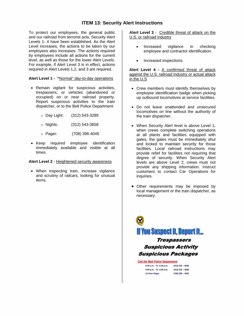
ITEM 13: Security Alert Instructions To protect our employees, the general public and our railroad from terrorist acts, Security Alert Levels 1- 4 have been established. As the Alert Level increases, the actions to be taken by our employees also increases. The actions required by employees include all actions for the current level, as well as those for the lower Alert Levels. For example, if Alert Level 3 is in effect, actions required in Alert Levels 1,2, and 3 are required. Alert Level 1 - “Normal" day-to-day operations • Remain vigilant for suspicious activities,
trespassers, or vehicles (abandoned or occupied) on or near railroad property. Report suspicious activities to the train dispatcher, or to the Belt Police Department
o Day Light: (312) 543-3289
o Nights: (312) 543-3658
o Pager: (708) 396-4045
• Keep required employee identification immediately available and visible at all times.
Alert Level 2 - Heightened security awareness • When inspecting train, increase vigilance
and scrutiny of railcars, looking for unusual items.
Alert Level 3 - Credible threat of attack on the U.S. or railroad industry
• Increased vigilance in checking employee and contractor identification.
• Increased inspections.
Alert Level 4 - A confirmed threat of attack against the U.S. railroad industry or actual attack in the U.S • Crew members must identify themselves by
employee identification badge when picking up outbound locomotives at service facilities.
• Do not leave unattended and unsecured
locomotives on line without the authority of the train dispatcher.
• When Security Alert level is above Level 1,
when crews complete switching operations at all plants and facilities equipped with gates, the gates must be immediately shut and locked to maintain security for those facilities. Local railroad instructions may provide relief for facilities not requiring that degree of security. When Security Alert levels are above Level 2, crews must not provide any shipping information. Instruct customers to contact Car Operations for inquiries.
• Other requirements may be imposed by
local management or the train dispatcher, as necessary.
Call the Belt Police DepartmentCall the Belt Police Department6:00 a.m. To 6:00 p.m. (312) 543 – 8269
6:00 p.m. To 6:00 a.m. (312) 543 – 3658
24 Hour Pager (708) 396 – 4045

THE BELT RAILWAY COMPANY
OF CHICAGO
Linear Operations Profile
as reflected in the Chicago CORA Guide* July 15, 2007
* provided as information only. Governing document is BRC Timetable #4 and Special Instructions. General Order updates will not modify these pages. Modifications, if necessary, are to be made by the employee.

Effective August 13, 2007 TIMETABLE / SPECIAL INSTRUCTIONS
50
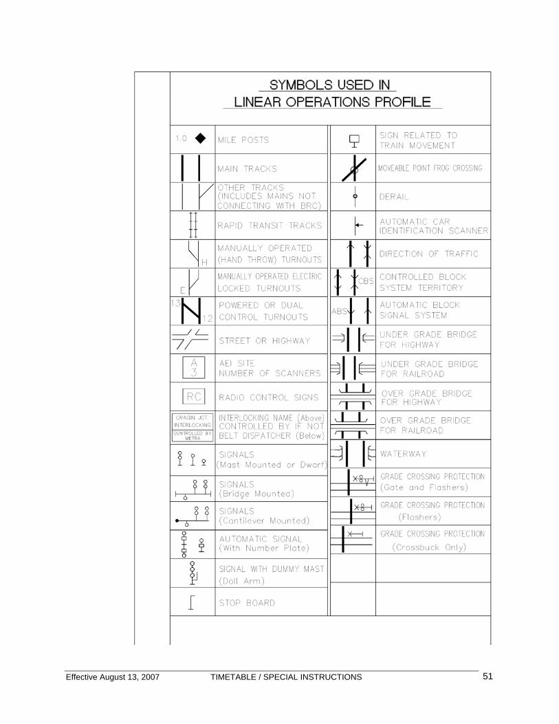
Effective August 13, 2007 TIMETABLE / SPECIAL INSTRUCTIONS
51

Effective August 13, 2007 TIMETABLE / SPECIAL INSTRUCTIONS
52
KENTON SUBDIVISION MUTLIPLE MAIN TRACKS – CTC MP 0.0 – MP 2.0 DISPATCHER: NORTH Radio – 3939 Speed Restrictions MP Description MPH -
Main Track 25
Tracks other than Main Tracks and Sidings unless otherwise designated
10
Speed Restrictions – Turnouts and Crossovers: MP Description MPH -
Main Track Turnouts except those noted below
15
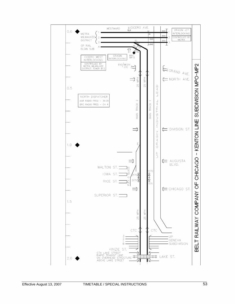
Effective August 13, 2007 TIMETABLE / SPECIAL INSTRUCTIONS
53
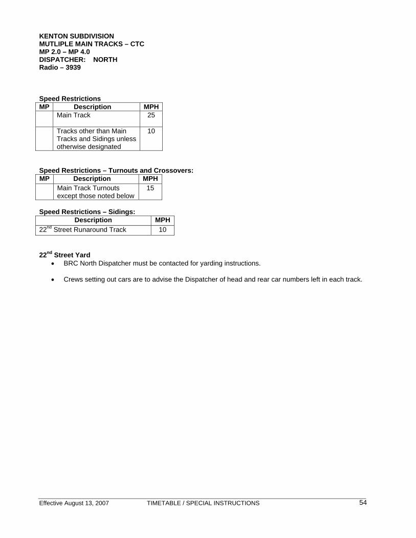
Effective August 13, 2007 TIMETABLE / SPECIAL INSTRUCTIONS
54
KENTON SUBDIVISION MUTLIPLE MAIN TRACKS – CTC MP 2.0 – MP 4.0 DISPATCHER: NORTH Radio – 3939 Speed Restrictions MP Description MPH -
Main Track 25
Tracks other than Main Tracks and Sidings unless otherwise designated
10
Speed Restrictions – Turnouts and Crossovers: MP Description MPH -
Main Track Turnouts except those noted below
15
Speed Restrictions – Sidings:
Description MPH 22nd Street Runaround Track 10 22nd Street Yard
• BRC North Dispatcher must be contacted for yarding instructions. • Crews setting out cars are to advise the Dispatcher of head and rear car numbers left in each track.

Effective August 13, 2007 TIMETABLE / SPECIAL INSTRUCTIONS
55
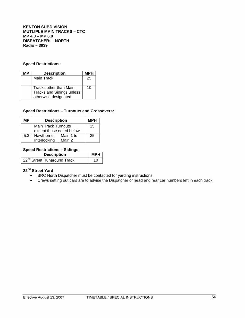
Effective August 13, 2007 TIMETABLE / SPECIAL INSTRUCTIONS
56
KENTON SUBDIVISION MUTLIPLE MAIN TRACKS – CTC MP 4.0 – MP 6.0 DISPATCHER: NORTH Radio – 3939 Speed Restrictions: MP Description MPH
Main Track 25
Tracks other than Main Tracks and Sidings unless otherwise designated
10
Speed Restrictions – Turnouts and Crossovers: MP Description MPH Main Track Turnouts
except those noted below 15
5.3 Hawthorne Interlocking
Main 1 to Main 2
25
Speed Restrictions – Sidings:
Description MPH 22nd Street Runaround Track 10 22nd Street Yard
• BRC North Dispatcher must be contacted for yarding instructions. • Crews setting out cars are to advise the Dispatcher of head and rear car numbers left in each track.
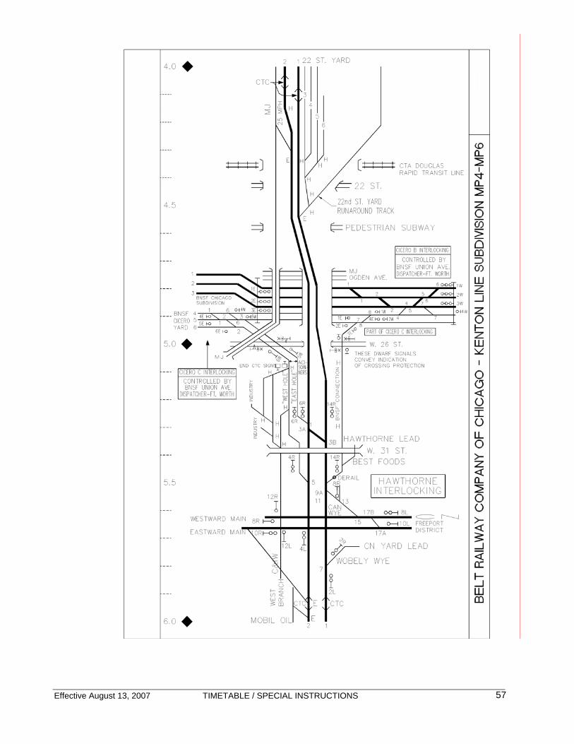
Effective August 13, 2007 TIMETABLE / SPECIAL INSTRUCTIONS
57

Effective August 13, 2007 TIMETABLE / SPECIAL INSTRUCTIONS
58
KENTON SUBDIVISION MUTLIPLE MAIN TRACKS – CTC MP 6.0 – MP 8.0 DISPATCHER: NORTH Radio – 3939 Speed Restrictions MP Description MPH
Main Track 25
Tracks other than Main Tracks and Sidings unless otherwise designated
10
Speed Restrictions – Turnouts and Crossovers: MP Description MPH Main Track Turnouts except
those noted below 15
6.6 LeMoyne Interlocking
Main 1 to Main 2
25
6.7 LeMoyne Interlocking
Main 1 to Main 2
25
7.9 55th Street Interlocking
Main 1 to Main 2
25
8.1 55th Street Interlocking
Main 2 to 59th Street Subdivision
25
8.1 55th Street Interlocking
Main 1 to 59th Street Subdivision
25
Speed Restrictions – Sidings:
Description MPH C&A Siding 10 5.8.2 (7) Sounding Whistles Whistle must be sounded at Archer Avenue. 911 Crossings-Emergency Communication: Trains stopped or anticipated to be obstructing these crossings for more than ten (10) minutes, train crew must notify the train dispatcher immediately. A crew member must notify the train dispatcher when the train is clear of the crossing.
Subdivision Crossing Location Kenton Line Archer and Kolmar
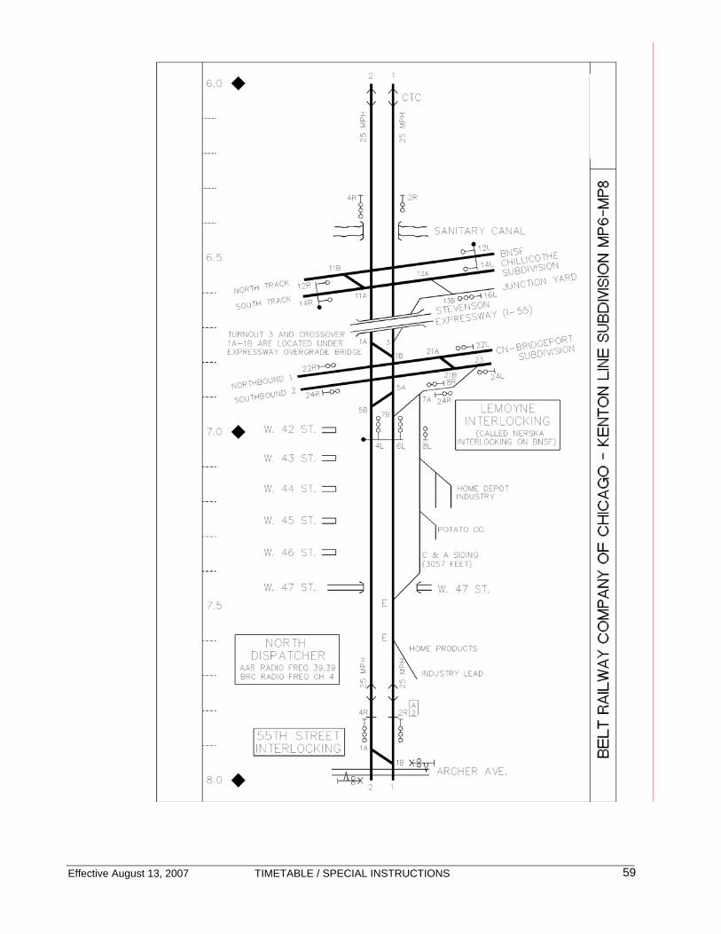
Effective August 13, 2007 TIMETABLE / SPECIAL INSTRUCTIONS
59

Effective August 13, 2007 TIMETABLE / SPECIAL INSTRUCTIONS
60
KENTON SUBDIVISION MUTLIPLE MAIN TRACKS – CTC MP 8.0 – MP 10.0 ELSDON IND LEAD – 6.28 DISPATCHER: NORTH Radio – 3939 DISPATCHER: SOUTH Radio - 2626 Speed Restrictions MP Description MPH
Main Track 25
Tracks other than Main Tracks and Sidings unless otherwise designated
10
Speed Restrictions – Turnouts and Crossovers: MP Description MPH Main Track Turnouts except
those noted below 15
7.9 55th Street Interlocking
Main 1 to Main 2
25
8.1 55th Street Interlocking
Main 2 to 59th Street Subdivision
25
8.1 55th Street Interlocking
Main 1 to 59th Street Subdivision
25
5.8.2 (7) Sounding Whistles Whistle must be sounded at Archer Avenue. 911 Crossings-Emergency Communication: Trains stopped or anticipated to be obstructing these crossings for more than ten (10) minutes, train crew must notify the train dispatcher immediately. A crew member must notify the train dispatcher when the train is clear of the crossing.
Subdivision Crossing Location Kenton Line Archer and Kolmar Kenton Line 4700 W. 55th Street Kenton Line 4700 W. 59th Street Kenton Line 4700 W. 63rd Street Kenton Line 4700 W. Marquette
Elsdon Industrial Lead • BRC trackage extends between 55th St.
Interlocking and MP 1.5. • BRC Dispatcher must be contacted to
obtain authority to occupy the Elsdon Industrial Lead.
• BRC Dispatcher must be contacted when
clear of the Elsdon Industrial Lead. • Movements towards BNSF Corwith Yard
governed by GCOR 6.28. BNSF Corwith Yardmaster must be contacted via radio (AAR 36-36) for authority to enter trackage.
• Movement towards the CN Elsdon
Industrial Track is governed by CN USOR 520 “Movement on other than Main Track” (same as GCOR 6.28). CN Train Dispatcher #4 must be contacted via radio (AAR 28-28) for authority to enter trackage.
• Movement towards the NS 49th Street Line
on No. 2 and No. 3 Industrial Tracks is governed by the Ashland Avenue Yardmaster via radio (AAR 64-64) for authority to enter trackage.

Effective August 13, 2007 TIMETABLE / SPECIAL INSTRUCTIONS
61
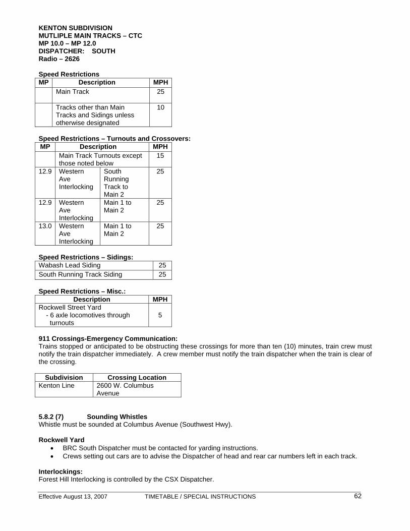
Effective August 13, 2007 TIMETABLE / SPECIAL INSTRUCTIONS
62
KENTON SUBDIVISION MUTLIPLE MAIN TRACKS – CTC MP 10.0 – MP 12.0 DISPATCHER: SOUTH Radio – 2626 Speed Restrictions MP Description MPH
Main Track 25
Tracks other than Main Tracks and Sidings unless otherwise designated
10
Speed Restrictions – Turnouts and Crossovers: MP Description MPH Main Track Turnouts except
those noted below 15
12.9 Western Ave Interlocking
South Running Track to Main 2
25
12.9 Western Ave Interlocking
Main 1 to Main 2
25
13.0 Western Ave Interlocking
Main 1 to Main 2
25
Speed Restrictions – Sidings: Wabash Lead Siding 25 South Running Track Siding 25 Speed Restrictions – Misc.:
Description MPH Rockwell Street Yard - 6 axle locomotives through turnouts
5
911 Crossings-Emergency Communication: Trains stopped or anticipated to be obstructing these crossings for more than ten (10) minutes, train crew must notify the train dispatcher immediately. A crew member must notify the train dispatcher when the train is clear of the crossing.
Subdivision Crossing Location Kenton Line 2600 W. Columbus
Avenue 5.8.2 (7) Sounding Whistles Whistle must be sounded at Columbus Avenue (Southwest Hwy). Rockwell Yard
• BRC South Dispatcher must be contacted for yarding instructions. • Crews setting out cars are to advise the Dispatcher of head and rear car numbers left in each track.
Interlockings: Forest Hill Interlocking is controlled by the CSX Dispatcher.
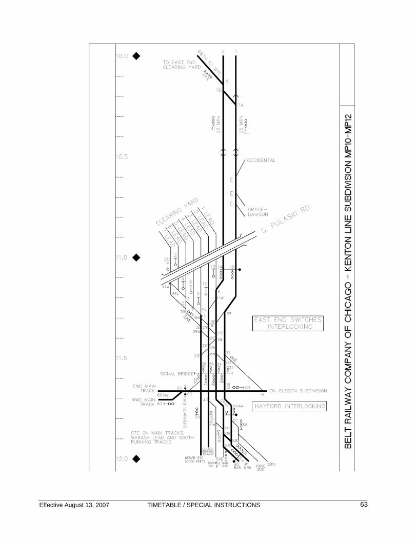
Effective August 13, 2007 TIMETABLE / SPECIAL INSTRUCTIONS
63

Effective August 13, 2007 TIMETABLE / SPECIAL INSTRUCTIONS
64
KENTON SUBDIVISION MUTLIPLE MAIN TRACKS – CTC MP 12.0 – MP 14.0 DISPATCHER: SOUTH Radio – 2626 Speed Restrictions MP Description MPH
Main Track 25
Tracks other than Main Tracks and Sidings unless otherwise designated
10
Speed Restrictions – Turnouts and Crossovers: MP Description MPH Main Track Turnouts except
those noted below 15
12.9 Western Avenue Interlocking
South Running Track to Main 2
25
12.9 Western Ave Interlocking
Main 1 to Main 2
25
13.0 Western Ave Interlocking
Main 1 to Main 2
25
13.6 Western Ave Interlocking
Main 1 to CSX Blue Island Subdivision
25
14.0 Belt Junction Interlocking
All Turnouts 25
Interlockings: Forest Hill Interlocking is controlled by the CSX Dispatcher. 5.8.2 (7) Sounding Whistles Whistle must be sounded at Columbus Avenue (Southwest Hwy).

Effective August 13, 2007 TIMETABLE / SPECIAL INSTRUCTIONS
65

Effective August 13, 2007 TIMETABLE / SPECIAL INSTRUCTIONS
66
KENTON SUBDIVISION MUTLIPLE MAIN TRACKS – CTC MP 14.0 – MP 16.0 DISPATCHER: SOUTH Radio – 2626 Speed Restrictions MP Description MPH
Main Track 25
Tracks other than Main Tracks and Sidings unless otherwise designated
10
Speed Restrictions – Turnouts and Crossovers: MP Description MPH Main Track Turnouts except
those noted below 15
14.0 Belt Jct Interlocking
All Turnouts 25
15.6 80th Street Interlocking
Main 1 to Main 2
25
15.7 80th Street Interlocking
Belt 3 to Main 2
25
15.9 80th Street Interlocking
Main 1 to Main 2
25
Speed Restrictions – Sidings:
Description MPHThird Rail Siding 10
87th Street Yard • BRC South Dispatcher must be contacted for yarding instructions. • Crews setting out cars are to advise the Dispatcher of head and rear car numbers left in each track.
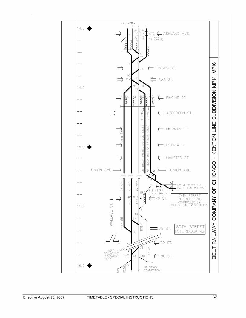
Effective August 13, 2007 TIMETABLE / SPECIAL INSTRUCTIONS
67
CTC CTC CTC

Effective August 13, 2007 TIMETABLE / SPECIAL INSTRUCTIONS
68
KENTON SUBDIVISION MUTLIPLE MAIN TRACKS – CTC MP 16.0 – MP 18.0 DISPATCHER: SOUTH Radio – 2626 Speed Restrictions MP Description MPH
Main Track 25
Tracks other than Main Tracks and Sidings unless otherwise designated
10
Speed Restrictions – Turnouts and Crossovers: MP Description MPH Main Track Turnouts except
those noted below 15
15.6 80th Street Interlocking
Main 1 to Main 2
25
15.7 80th Street Interlocking
Belt 3 to Main 2
25
15.9 80th Street Interlocking
Main 1 to Main 2
25
Speed Restrictions – Sidings:
Description MPHThird Rail Siding 10
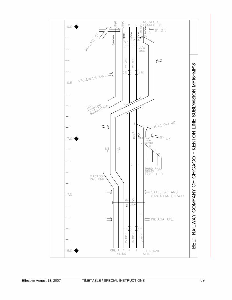
Effective August 13, 2007 TIMETABLE / SPECIAL INSTRUCTIONS
69
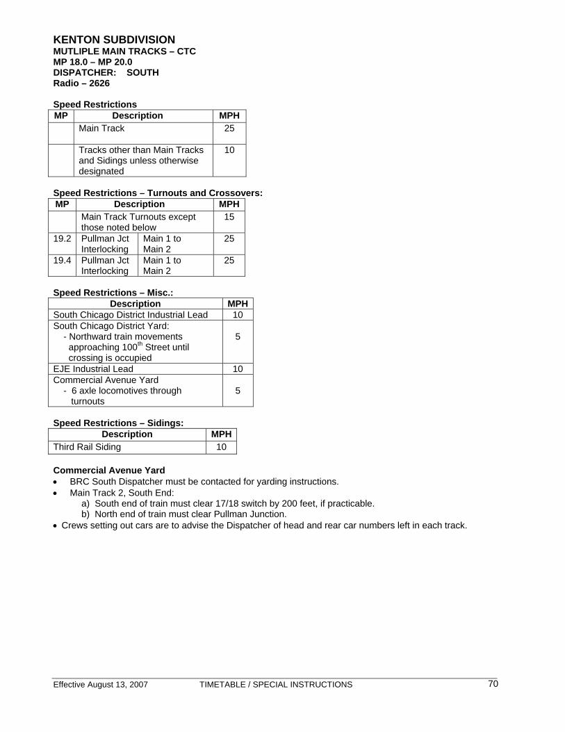
Effective August 13, 2007 TIMETABLE / SPECIAL INSTRUCTIONS
70
KENTON SUBDIVISION MUTLIPLE MAIN TRACKS – CTC MP 18.0 – MP 20.0 DISPATCHER: SOUTH Radio – 2626 Speed Restrictions MP Description MPH
Main Track 25
Tracks other than Main Tracks and Sidings unless otherwise designated
10
Speed Restrictions – Turnouts and Crossovers: MP Description MPH Main Track Turnouts except
those noted below 15
19.2 Pullman Jct Interlocking
Main 1 to Main 2
25
19.4 Pullman Jct Interlocking
Main 1 to Main 2
25
Speed Restrictions – Misc.:
Description MPHSouth Chicago District Industrial Lead 10 South Chicago District Yard: - Northward train movements approaching 100th Street until crossing is occupied
5
EJE Industrial Lead 10 Commercial Avenue Yard - 6 axle locomotives through turnouts
5
Speed Restrictions – Sidings:
Description MPHThird Rail Siding 10 Commercial Avenue Yard • BRC South Dispatcher must be contacted for yarding instructions. • Main Track 2, South End: a) South end of train must clear 17/18 switch by 200 feet, if practicable. b) North end of train must clear Pullman Junction. • Crews setting out cars are to advise the Dispatcher of head and rear car numbers left in each track.

Effective August 13, 2007 TIMETABLE / SPECIAL INSTRUCTIONS
71
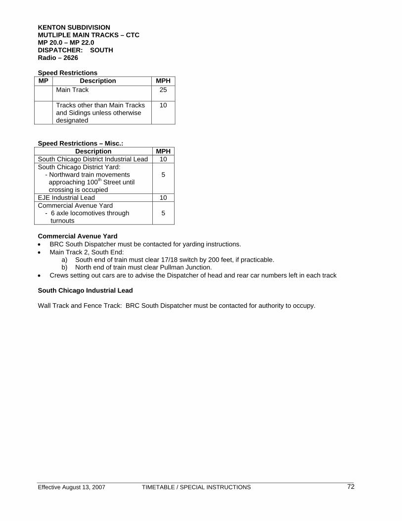
Effective August 13, 2007 TIMETABLE / SPECIAL INSTRUCTIONS
72
KENTON SUBDIVISION MUTLIPLE MAIN TRACKS – CTC MP 20.0 – MP 22.0 DISPATCHER: SOUTH Radio – 2626 Speed Restrictions MP Description MPH
Main Track 25
Tracks other than Main Tracks and Sidings unless otherwise designated
10
Speed Restrictions – Misc.:
Description MPHSouth Chicago District Industrial Lead 10 South Chicago District Yard: - Northward train movements approaching 100th Street until crossing is occupied
5
EJE Industrial Lead 10 Commercial Avenue Yard - 6 axle locomotives through turnouts
5
Commercial Avenue Yard • BRC South Dispatcher must be contacted for yarding instructions. • Main Track 2, South End:
a) South end of train must clear 17/18 switch by 200 feet, if practicable. b) North end of train must clear Pullman Junction.
• Crews setting out cars are to advise the Dispatcher of head and rear car numbers left in each track South Chicago Industrial Lead Wall Track and Fence Track: BRC South Dispatcher must be contacted for authority to occupy.

Effective August 13, 2007 TIMETABLE / SPECIAL INSTRUCTIONS
73

Effective August 13, 2007 TIMETABLE / SPECIAL INSTRUCTIONS
74
KENTON SUBDIVISION MUTLIPLE MAIN TRACKS – CTC MP 22.0 – MP 24.0 DISPATCHER: SOUTH Radio – 2626 Speed Restrictions MP Description MPH
Main Track 25
Tracks other than Main Tracks and Sidings unless otherwise designated
10
Speed Restrictions – Misc.:
Description MPHSouth Chicago District Industrial Lead 10 South Chicago District Yard: - Northward train movements approaching 100th Street until crossing is occupied
5
EJE Industrial Lead 10 Commercial Avenue Yard - 6 axle locomotives through turnouts
5
Commercial Avenue Yard
• BRC South Dispatcher must be contacted for yarding instructions. • Main Track 2, South End:
a) South end of train must clear 17/18 switch by 200 feet, if practicable. b) North end of train must clear Pullman Junction.
• Crews setting out cars are to advise the Dispatcher of head and rear car numbers left in each track. South Chicago Industrial Lead Wall Track and Fence Track: BRC South Dispatcher must be contacted for authority to occupy.

Effective August 13, 2007 TIMETABLE / SPECIAL INSTRUCTIONS
75
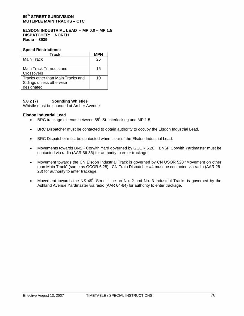
Effective August 13, 2007 TIMETABLE / SPECIAL INSTRUCTIONS
76
59th STREET SUBDIVISION MUTLIPLE MAIN TRACKS – CTC ELSDON INDUSTRIAL LEAD – MP 0.0 – MP 1.5 DISPATCHER: NORTH Radio – 3939 Speed Restrictions:
Track MPH Main Track
25
Main Track Turnouts and Crossovers
15
Tracks other than Main Tracks and Sidings unless otherwise designated
10
5.8.2 (7) Sounding Whistles Whistle must be sounded at Archer Avenue Elsdon Industrial Lead
• BRC trackage extends between 55th St. Interlocking and MP 1.5. • BRC Dispatcher must be contacted to obtain authority to occupy the Elsdon Industrial Lead. • BRC Dispatcher must be contacted when clear of the Elsdon Industrial Lead. • Movements towards BNSF Corwith Yard governed by GCOR 6.28. BNSF Corwith Yardmaster must be
contacted via radio (AAR 36-36) for authority to enter trackage. • Movement towards the CN Elsdon Industrial Track is governed by CN USOR 520 “Movement on other
than Main Track” (same as GCOR 6.28). CN Train Dispatcher #4 must be contacted via radio (AAR 28-28) for authority to enter trackage.
• Movement towards the NS 49th Street Line on No. 2 and No. 3 Industrial Tracks is governed by the
Ashland Avenue Yardmaster via radio (AAR 64-64) for authority to enter trackage.

Effective August 13, 2007 TIMETABLE / SPECIAL INSTRUCTIONS
77

Effective August 13, 2007 TIMETABLE / SPECIAL INSTRUCTIONS
78
59th STREET SUBDIVISION MUTLIPLE MAIN TRACKS – CTC MP 0.0 – MP 2.0 DISPATCHER: NORTH Radio – 3939 Speed Restrictions:
Track MPH Main Track
25
Main Track Turnouts and Crossovers
15
Tracks other than Main Tracks and Sidings unless otherwise designated
10
911 Crossings-Emergency Communication: Trains stopped or anticipated to be obstructing these crossings for more than ten (10) minutes, train crew must notify the train dispatcher immediately. A crew member must notify the train dispatcher when the train is clear of the crossing.
Subdivision Crossing Location 59th Street 5400 W. Central Avenue 59th Street 5600 W. 55th Street

Effective August 13, 2007 TIMETABLE / SPECIAL INSTRUCTIONS
79

Effective August 13, 2007 TIMETABLE / SPECIAL INSTRUCTIONS
80
59th STREET SUBDIVISION MUTLIPLE MAIN TRACKS – CTC MP 2.0 – MP 4.0 DISPATCHER: NORTH Radio – 3939 Speed Restrictions:
Track MPH Main Track
25
Main Track Turnouts and Crossovers
15
Tracks other than Main Tracks and Sidings unless otherwise designated
10
911 Crossings-Emergency Communication: Trains stopped or anticipated to be obstructing these crossings for more than ten (10) minutes, train crew must notify the train dispatcher immediately. A crew member must notify the train dispatcher when the train is clear of the crossing.
Subdivision Crossing Location 59th Street 5932 S. Narragansett

Effective August 13, 2007 TIMETABLE / SPECIAL INSTRUCTIONS
81
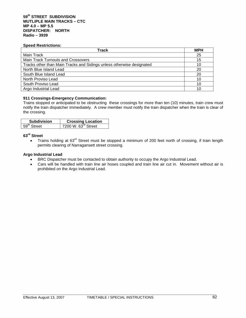
Effective August 13, 2007 TIMETABLE / SPECIAL INSTRUCTIONS
82
59th STREET SUBDIVISION MUTLIPLE MAIN TRACKS – CTC MP 4.0 – MP 5.5 DISPATCHER: NORTH Radio – 3939 Speed Restrictions:
Track MPH Main Track 25 Main Track Turnouts and Crossovers 15 Tracks other than Main Tracks and Sidings unless otherwise designated 10 North Blue Island Lead 20 South Blue Island Lead 20 North Proviso Lead 10 South Proviso Lead 10 Argo Industrial Lead 10
911 Crossings-Emergency Communication: Trains stopped or anticipated to be obstructing these crossings for more than ten (10) minutes, train crew must notify the train dispatcher immediately. A crew member must notify the train dispatcher when the train is clear of the crossing.
Subdivision Crossing Location 59th Street 7200 W. 63rd Street
63rd Street
• Trains holding at 63rd Street must be stopped a minimum of 200 feet north of crossing, if train length permits clearing of Narragansett street crossing.
Argo Industrial Lead
• BRC Dispatcher must be contacted to obtain authority to occupy the Argo Industrial Lead. • Cars will be handled with train line air hoses coupled and train line air cut in. Movement without air is
prohibited on the Argo Industrial Lead.

Effective August 13, 2007 TIMETABLE / SPECIAL INSTRUCTIONS
83

Effective August 13, 2007 TIMETABLE / SPECIAL INSTRUCTIONS
84
59th STREET SUBDIVISION MUTLIPLE MAIN TRACKS – CTC WEST SUB DISPATCHER: NORTH Radio – 3939 Speed Restrictions:
Track MPH Main Track 25 Main Track Turnouts and Crossovers 15 Tracks other than Main Tracks and Sidings unless otherwise designated 10 North Blue Island Lead 20 South Blue Island Lead 20 North Proviso Lead 10 South Proviso Lead 10 Argo Industrial Lead 10
Argo Industrial Lead • BRC Dispatcher must be contacted to obtain authority to occupy the Argo Industrial Lead. • Cars will be handled with train line air hoses coupled and train line air cut in. Movement without air is
prohibited on the Argo Industrial Lead.
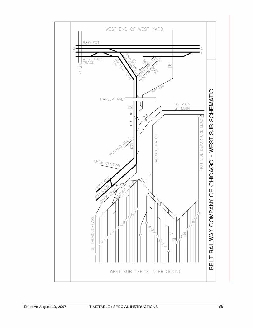
Effective August 13, 2007 TIMETABLE / SPECIAL INSTRUCTIONS
85

Effective August 13, 2007 TIMETABLE / SPECIAL INSTRUCTIONS
86
CLEARING YARD – 6.28 Radio Humpmaster - 5757 West YDM - 1818 East YDM - 8989 Diesel Shop - 7979 Speed Restrictions:
Tracks MPH All Tracks other than Main Tracks unless otherwise designated
10
South Thoroughfare 10 North Thoroughfare 10 Locomotive Service Tracks - EXCEPTION: North Thoroughfare Mechanical controlled limits
5 10
Rip Tracks 5 Operating Characteristics:
Tracks Authority 1 – 2 Leads, East Receiving Yard Humpmaster 3 – 7 Leads, East Receiving Yard East Yardmaster East Receiving Yard Humpmaster East Approach Tracks, Tracks 1 – 4 Humpmaster East Class Yard, Tracks 1 – 63 East Yardmaster East Class Yard, Tracks 64 – 65 Car Department East Departure Yard East Yardmaster Martin Yard CSXI Bedford Park West Receiving Yard Humpmaster West Approach Tracks, Tracks 1 - 5 Humpmaster West Class Yard West Yardmaster West Departure Yard West Yardmaster Cabbage Patch Lead, West Departure Yard West Yardmaster High Side Lead, West Departure Yard West Yardmaster South Thoroughfare, Cicero Avenue to Central Avenue East Yardmaster South Thoroughfare, Central Avenue to 6 XO. (Back Lead) Humpmaster Back Lead Humpmaster North Thoroughfare, West Yard Office to Central Avenue
• Except designated Mechanical Department controlled limits as identified by posted signage
West Yardmaster
North Thoroughfare, Central Avenue to Cicero Avenue • Except designated Mechanical Department controlled limits
as identified by posted signage
Humpmaster
Locomotive Service Tracks • Including North Thoroughfare Mechanical Department
controlled limits as identified by posted signage
Diesel Shop
67th Street / 68th Street, including Wye tracks Humpmaster
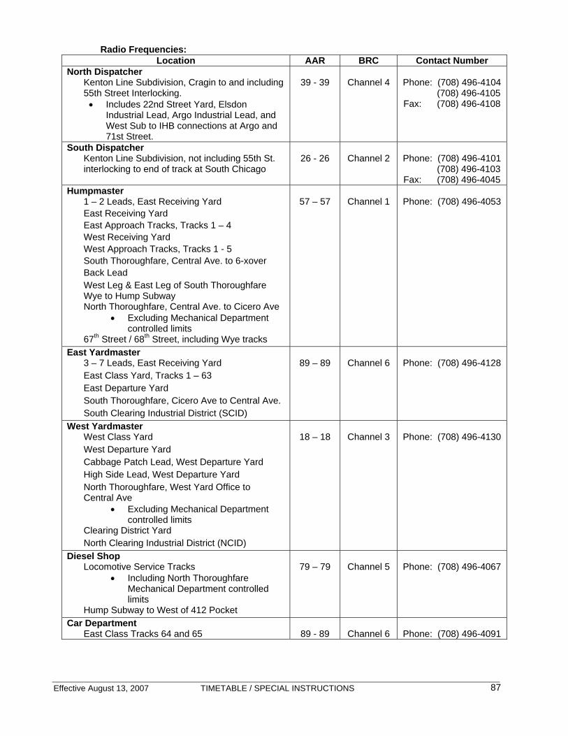
Effective August 13, 2007 TIMETABLE / SPECIAL INSTRUCTIONS
87
Radio Frequencies: Location AAR BRC Contact Number
North Dispatcher Kenton Line Subdivision, Cragin to and including 55th Street Interlocking. • Includes 22nd Street Yard, Elsdon
Industrial Lead, Argo Industrial Lead, and West Sub to IHB connections at Argo and 71st Street.
39 - 39
Channel 4
Phone: (708) 496-4104 (708) 496-4105 Fax: (708) 496-4108
South Dispatcher Kenton Line Subdivision, not including 55th St. interlocking to end of track at South Chicago
26 - 26
Channel 2
Phone: (708) 496-4101 (708) 496-4103 Fax: (708) 496-4045
Humpmaster 1 – 2 Leads, East Receiving Yard East Receiving Yard East Approach Tracks, Tracks 1 – 4 West Receiving Yard West Approach Tracks, Tracks 1 - 5 South Thoroughfare, Central Ave. to 6-xover Back Lead West Leg & East Leg of South Thoroughfare Wye to Hump Subway North Thoroughfare, Central Ave. to Cicero Ave
• Excluding Mechanical Department controlled limits
67th Street / 68th Street, including Wye tracks
57 – 57
Channel 1
Phone: (708) 496-4053
East Yardmaster 3 – 7 Leads, East Receiving Yard East Class Yard, Tracks 1 – 63 East Departure Yard South Thoroughfare, Cicero Ave to Central Ave. South Clearing Industrial District (SCID)
89 – 89
Channel 6
Phone: (708) 496-4128
West Yardmaster West Class Yard West Departure Yard Cabbage Patch Lead, West Departure Yard High Side Lead, West Departure Yard North Thoroughfare, West Yard Office to Central Ave
• Excluding Mechanical Department controlled limits
Clearing District Yard North Clearing Industrial District (NCID)
18 – 18
Channel 3
Phone: (708) 496-4130
Diesel Shop Locomotive Service Tracks
• Including North Thoroughfare Mechanical Department controlled limits
Hump Subway to West of 412 Pocket
79 – 79
Channel 5
Phone: (708) 496-4067
Car Department East Class Tracks 64 and 65
89 - 89
Channel 6
Phone: (708) 496-4091

BRC CLEARING YARD


The Belt Railway Company of Chicago
Expects 2 things of all employees ….
Take the Extra 5 Minutes to Perform the Task Safely
And
Abide by the Rules
Related Documents