Timed coloured Petri nets and their application to logistics Citation for published version (APA): Aalst, van der, W. M. P. (1992). Timed coloured Petri nets and their application to logistics. [Phd Thesis 1 (Research TU/e / Graduation TU/e), Mathematics and Computer Science]. Technische Universiteit Eindhoven. https://doi.org/10.6100/IR381309 DOI: 10.6100/IR381309 Document status and date: Published: 01/01/1992 Document Version: Publisher’s PDF, also known as Version of Record (includes final page, issue and volume numbers) Please check the document version of this publication: • A submitted manuscript is the version of the article upon submission and before peer-review. There can be important differences between the submitted version and the official published version of record. People interested in the research are advised to contact the author for the final version of the publication, or visit the DOI to the publisher's website. • The final author version and the galley proof are versions of the publication after peer review. • The final published version features the final layout of the paper including the volume, issue and page numbers. Link to publication General rights Copyright and moral rights for the publications made accessible in the public portal are retained by the authors and/or other copyright owners and it is a condition of accessing publications that users recognise and abide by the legal requirements associated with these rights. • Users may download and print one copy of any publication from the public portal for the purpose of private study or research. • You may not further distribute the material or use it for any profit-making activity or commercial gain • You may freely distribute the URL identifying the publication in the public portal. If the publication is distributed under the terms of Article 25fa of the Dutch Copyright Act, indicated by the “Taverne” license above, please follow below link for the End User Agreement: www.tue.nl/taverne Take down policy If you believe that this document breaches copyright please contact us at: [email protected] providing details and we will investigate your claim. Download date: 25. Sep. 2022

Welcome message from author
This document is posted to help you gain knowledge. Please leave a comment to let me know what you think about it! Share it to your friends and learn new things together.
Transcript

Timed coloured Petri nets and their application to logistics
Citation for published version (APA):Aalst, van der, W. M. P. (1992). Timed coloured Petri nets and their application to logistics. [Phd Thesis 1(Research TU/e / Graduation TU/e), Mathematics and Computer Science]. Technische Universiteit Eindhoven.https://doi.org/10.6100/IR381309
DOI:10.6100/IR381309
Document status and date:Published: 01/01/1992
Document Version:Publisher’s PDF, also known as Version of Record (includes final page, issue and volume numbers)
Please check the document version of this publication:
• A submitted manuscript is the version of the article upon submission and before peer-review. There can beimportant differences between the submitted version and the official published version of record. Peopleinterested in the research are advised to contact the author for the final version of the publication, or visit theDOI to the publisher's website.• The final author version and the galley proof are versions of the publication after peer review.• The final published version features the final layout of the paper including the volume, issue and pagenumbers.Link to publication
General rightsCopyright and moral rights for the publications made accessible in the public portal are retained by the authors and/or other copyright ownersand it is a condition of accessing publications that users recognise and abide by the legal requirements associated with these rights.
• Users may download and print one copy of any publication from the public portal for the purpose of private study or research. • You may not further distribute the material or use it for any profit-making activity or commercial gain • You may freely distribute the URL identifying the publication in the public portal.
If the publication is distributed under the terms of Article 25fa of the Dutch Copyright Act, indicated by the “Taverne” license above, pleasefollow below link for the End User Agreement:www.tue.nl/taverne
Take down policyIf you believe that this document breaches copyright please contact us at:[email protected] details and we will investigate your claim.
Download date: 25. Sep. 2022


TIMED COLOURED PETRI NETS
AND THEIR APPLICATION
TO LOGISTICS

The study reported in this monograph is sponsored by the l'NO lnstitute for Production and L\)gistics (IPL) as part of the TASTE project.

TIMED COLOURED PETRI NETS
AND THEIR APPLICATION
TO LOGISTICS
PROEFSCHRIFf
ter verkrijging van de graad van doctor aan de
Technische Universiteit Eindhoven, op gezag van
de Rector Magnificus, prof. dr. J.H. van Lint.
voor een commissie aangewezen door het College
van Dekanen in het openbaar te verdedigen op
donderdag 17 september 1992 om 16.00 uur
door
Willibrordus Martinus Pancratius van der Aalst
geboren te Eersel
druK: wibro óissertatiaarukKoriJ, holmona_

Dit proefschrift is goedgekeurd door de promotoren prof. dr. J. Wessels en prof. dr. K.M. van Hee

Contents
1 Introduetion 1.1 Problem statement . . . . . . 1.2 Petri nets . . . . . . . . . . . 1.3 Time and colour in Petri nets
1.3.1 Adding colour ..... 1.3.2 Adding time . . . . . .
1.4 Analysis of timed coloured Petri nets 1.4.1 Currently used analysis methods 1.4.2 Analysis methods based on the ITCPN model
1.5 ExSpect . . . . . . . . 1.6 Application to logistics .. 1. 7 Other methods . . . . . . 1.8 Outline of this monograph
2 A timed colonred Petri net model 2.1 Introduetion ... . 2.2 Notations .... . 2.3 Transition systems 2.4 The model . . . . .
2.4.1 Semantics of an ITCPN 2.4.2 Alternative firing rules
2.5 Some further concepts and properties 2.6 lnteresting performance measures 2. 7 Condusion . . . . . . . . . . . . . . .
3 Analysis of time in nets 3.1 Introduetion ................ . 3.2 Method ATCFN .............. .
3.2.1 Application to project engineering. 3.3 Metbod MTSRT . . . . . . . . . . . . . .
3.3.1 The modified transition system .. 3.3.2 Using the modified transition system
3.4 Method PNRT . . . . . . . . . . . . . 3.5 Dealing with large colour sets . . . . .
3.5.1 Approach 1: remove the colour
1 1 4 6 6 7
10 10 12 16 18 19 22
23 23 25 29 34 37 41 47 f)8 64
67 67 71 76 79 82 89 97
. 108
. 110

11
3.5.2 · Approach 2: refine the net 3.6 An example 3. 7 Condusion . 3.8 Appendix
4 Language and tooi 4.1 Motivation .... 4.2 The language ..
4.2.1 Type definitions . 4.2.2 Function definitions . 4.2.3 Processor definitions 4.2.4 System definitions
4.3 The software package . . . . 4.3.1 The shell ...... . 4.3.2 The design interface 4.3.3 The type checker . . 4.3.4 The interpreter and the runtime interface . 4.3.5 The ITPN Analysis Tooi . .
4.4 Engineering the modelling process . 4.5 A library: QNM . . . . . .
5 Modelling logistic systems 5.1 Introduetion . . . 5.2 Logistics . . . . . . . . . . 5.3 Why Petri nets ? . . . . . 5.4 Structuring logistic systems
5.4.1 Typicallogistic activities . 5.4.2 Typical control structures
5.5 A logistic lihrary . . . . . . 5.5.1 The type definitions 5.5.2 The supply system 5.5.3 The demand system 5.5.4 The production unit 5.5.5 The stock point . . . 5.5.6 The transport system .
5.6 Some guidelines ....... . 5. 7 An example . . . . . . . . . .
5.7.1 The present situation . 5. 7.2 Alternatives
5.8 Condusion .......... .
6 Condusions and further research
Bibliography
CONTENTS
. 115
. 125
. 135
. 140
145 . 145 . 146 . 147 . 148 . 149 . 151 . 157 . 159 . 159 . 161 . 161 . 161 . 165 . 167
175 . 175 . 176 • 180 .192 . 199 . 201 . 208 . 210 . 213 . 216 . 218 . 222 . 227 . 231 . 236 . 236 . 242 . 242
245
249

CONTENTS
Index
Samenvatting
Curriculum vitae
111
260
265
267

Chapter 1
Introduetion
1.1 Problem statement
Recently, logistics has become an important issue in many organizations. This is a direct consequence of the fact that modern organizations are required to offer a wide variety of products, in less time and at reduced prices. To improve their logistics function, many organizations have integrated the control of the logistic activities such as production, transportation, storage, acquisition and distribution. This integration complicates the management of the logistic processes. The complexity of the control problems encountered in logistics urges the necessity of an integrated framework for the modelling and analysis of logistic systems.
This monograph focuses on the modelling and analysis of complex logistic systems and outlines solutions based on a timed coloured Petri net model. Although these solutions are useful in the context of logistics, their application is not limited to the logistic domain. Examples of other application domains which may benefit from the results presented in this monograph are: flexible manufacturing systems, distributed information systems and reai-time systems. In fact most of the results apply to systems which are:
dynamic The systems we are interested in are subject to changes. At any moment the system has a certain state, at a later time this state may have changed.
discrete We restriet ourselves to discrete systems, i.e. changes in the system occur discontinuously. These changes only happen at a fini te number of time points.
distributed A distributed system is composed of a number of autonorneus subsystems which interact and share resources in performing a specific task. These subsystems are often physically distributed.
In other words: we consider distributed .systems that change in a discrete fashion. We call these systems discrete dynamic systems.
We use a Petri net based approach to the modelling aud analysis of these discrete dynamic systems. Petrinets are appropriate for thc modelling of distributed systcms,

2 GRAPTER 1. INTRODUCTION
sirree they allow for the representation of parallelism and synchronization. However, the classic Petri net model is unsuitable for the modeHing of systems having large state spaces or a complex temporal behaviour. Therefore, we have developed a Petri net model extended with time and colour. This model is the foundation of a framework that has been developed to solve problems related to the design and control of complex discrete dynamic systems.
In this monograph, we focus on two important aspects of this framework:
modelling There are several reasous for modelling a system, e.g. to create and evaluate a design of a new system, to compare alternative designs a.nd to investigate possible improvements in a rea.l system. Model building forces us to organize, evaluate and examine the validity of our thoughts. This way modelling reveals errors and possible improvements.
The outcome of any modeHing process is a 'model'. We distinguish three kinds of models: (1) informal models, (2) mathematica! models and (3) formal specifications.
An inforrrial model is a verbal and/or graphical description of the system under consideration. Such a modelJacks forma! semantics.
Mathematica! models are those in which one or more aspects of a system are represented by mathematica! entities, like: equations, matrices, relations, Markov chains, graphs, etc. These models are often an abstraction of the real system in which simplifying assumptions are required if the model is to he solvable.
A forma! specification is a precise and structured description of (aspects of) a system. Such a specification is an abstraction of the real system, expressed in a specification language having a predefined syntax and semantics. Unlike most mathematica! models, a formal specification cannot he 'solved' analytically. However, most forma! specifications arebasedon a mathematica! model allowing for one or more kinds of analysis. Although analysis is possible by analysing the underlying model, the primary function of a formal specification is to provide a concise and unambiguous description of the system (i.e. a 'blueprint').
In this monograph we focus on specifications based on timed colonred Petri nets. A timed colonred Petri net is a mathematica! model which is suitable for the modelling of discrete dynamic systems.
The development of a good specification of a complex discrete dynamic system is often time consuming and requires considerable knowledge and experience. Therefore, there is a need for concepts and tools to facilitate the modelling process. Since we concentrate on logistics, we are particularly interested in concepts useful for the modelling of complex logistic systems. Consequently, some of the concepts we have developed apply to logistic systems in particular.

1.1. PROBLEM STATEMENT
discrete dynamic systems
logistic systems
modelling
forma! specification
timed coloured Petri net
analysis
answers and solutions
Figure 1.1: A survey of this monograph
3
analysis The outcome of the modeHing process is a specification which corresponds to a timed colonred Petri net. Analysis of this net may he useful to verify its correctness and to make statements ahout the performance of the system. It also helps the modeHer to understand the hehaviour of the system.
To analyse the dynamic behaviour of a timed colonred Petri net, we need analysis methods. Simulation is a suitahle technique for the analysis of this type of nets. Although simulation is flexihle and easy to use, there is an urge for other techniques which exploit the features of Petri nets extended with 'time' and 'colour'. Many analysis techniques developed for classic Petri nets have been extended for colonred nets. However, these techniques cannot he used to analyse the temporal behaviour of a timed coloured Petri net.
Therefore, we have developed a numher of powerful ana.lysis methods, three of which are presenteel in this monograph.
The purpose of this monograph is summarized in figure 1.1. On the onc hand this monograph discusses concepts and tools to fa.cilitate the modclling of logistic systems, on the other hand it provides methods to analyse tin1ed colonred Petri nets. These results are outlined in this monograph and are bascel on conccpts frorn Pctri

4 CllAPTER 1. INTRODUCTION
net theory, systems analysis and knowledge of logistics as an application domain.
1.2 Petri nets
The systems we consider are often very complex, large, discrete dynamic systems of many interading components. The componentsof such a system exhibit concurrency or parallelism, i.e. activities of one component may occur simultaneously with other components. The components of the system interact and sometimes they have to synchronize, i.e. one component waits for the other in order to execute an activity simultaneously. The Petri net formalism (Petri [102], Reisig [111]) was one of the first approaches introduced for dealing with concurrency and synchronization.
Historically speaking, Petri nets originate from the early work of Carl Adam Petri ([101]). Petd's work came to the attention of Holt and others of the lnformation System Theory Project of Applied Data Research, lnc, in the United States. Much of thc early theory and notation has been developed by this group ([65]). The work of Petri also came to the attention of Project MAC at the Massachusetts Institute of Technology (MIT), resulting in a number of publications and reports. Since the late-1970's, the use and study of Petri nets has increased considerably. Especially Europeans have been very active in the field of Petri nets. Research on and the application of Petri nets have become widespread activities. A review of the history of Petri nets and an extensive bibliography is given by Murata in [93].
The classic (or basic) Petri net is a directed bipartite graph with two node types called placcs and transitions. The nocles are connected via directed arcs. Conneetions between two nocles of the same type are not allowed. Places are represented by circles and transitions by bars. Places may contain zero or more tokens, drawn as black dots. The number of tokens may change during the execution of the net. A place p is called an input place of a transition t if there exists a directed are from p to t. A place pis called an output placc of a transition t if there exists a directed are frorn t top. Each transition puts a wcight toeach of its input and output places, i.e. each are is labelled with a weight (positive integer). A transition is called cnablcd if each of its input places contains at least a number of tokens equal to its weight. In other words, a transition is cnabled if all input places contain (at least) the specified numbcr of tokens. An enabled transition can fire. Firing a transition t means consuming tokens from the input places and producing tokens for the output places, i.e. t 'occms'. The nurnber of tokens produced for each of the output places is equal to the weight of the corresponding are. A state of a Petri net is a distri bution of tokens over the places. Many authors use the term marking to denote the state of a basic Pctri net. A firing sequence is a sequence of states 8 1 , s 2, 8 3, .. , such that any state s; is foliowed by a state si+1 , resulting from the firing of sorne enabled transition in state s;.
For a Pctri net which roodels a discrete dynamic system, we are often interested in

1.2. PETRINETS 5
properties, such as boundedness, liveness, safety and freedom of deadlock. Moreover, given an initia! state (marking), we are also interested in the reachability set, i.e. the set of all states visited by some firing sequence starting in this initia! state. To answer these questions, several analysis techniques have been suggested.
Most of the analysis techniques described in literature, either genera te a reachability graph or involve linear algebraic techniques.
A reachability graph is a graph representation of the reaebabie states and can he used to answer a variety of questions. Several reduction techniques have been developed to reduce the size of such a graph.
Linear algebraic techniques are often used to calculate invariants. Note that a marking can be represented as a vector, and a Petri net can be represented as a set of linear algebrak equations. Invariants are characteristic solutions of these equations. Therefore, it is possible to compute tbem by linear algebraic techniques. An example of an invariant is a so-called place invariant, this invariant assigns a weight to each place, such that the weighted token count remains constant during the execution of any firing sequence.
For an introduetion to basic Petri nets and their analysis we refer to Reisig ( lll] and Petersou [100].
Since the beginning of the 1970's the study of Petri nets bas developed in two directions: pure Petri net theory and applied Petri net theory.
The first line of research concentrates on the fundamental theory of Petri nets. People working on this line of research are mainly concerned with the development of a firm mathematica! foundation of Petri net theory. Although the results of this kind of research are useful, many techniques and concepts developed in this area are difficult to apply to problems encountered in practice.
The secoud line of research is concerned with the application of Petri nets to the modelling and analysis of systems. Typical application areas are communication protocols, computer systems, distributed systems, production systems and tlexible manufacturing systems. In applying Petri nets, it is often necessary to extend the basic Petri net modeU These extensions do not allow the use of many techniques developed in the field of purePetri net theory. Fortunately, many of these techniques have been generalized to coloured Petri nets.
Both directions did not lead to a comprehensive frameworkof Petri nets, which fully utilizes the analysis capabilities and is applicable in practice. Consequently, there is still a great gulf between pure and applied Petri net theory. This rnonograph describes concepts and techniques which are useful for bridging this gulf.
that we use the term 'Petri net model ' to denote a forma! dcfinition of Pctri nets, such a model is in fact a meta-model, si nee it is used to describe modelsof systems.
6 GRAPTER 1. INTRODUCTION
1.3 Time and colour in Petri nets
The basic Petri net model is not suitable for the modelling of many systems encountered in logistics, production, communication, flexible manufacturing and information processing. Petri nets descrihing real systems tend to he complex and extremely large. Sometimes, it is even impossible to model the behaviour of the system accurately. To solve these problems many authors propose extensions of the basic Petri net model.
We distinguish two kinds of extensions: (1) extensions to increase the modeHing power and (2) extensions to merely facilitate the user in making more succinct and manageable models. Examples of extensions that do not increase the power of a Petri net model are multiple arcs and places with capacity constraints (see Murata [93]). On the other hand there are extensions, such as inhibitor arcs ('zero test') and priorities (Peterson (100], Pagnoni [97]), that do increase the modeHing power. Wh en ad ding these extensions, carefut at tention must he paid to the tradeoff between modeHing and analysis capability. That is, the more general the model, the more difficult it is to analyse.
The approach presented in this monograph is based on a timed coloured Petri net model, called the Interval Timed Coloured Petri Net (ITCPN) model. We start with an informal introduetion to the ITCPN model by relating it toother timed and/or colonred Petri net models known in literature.
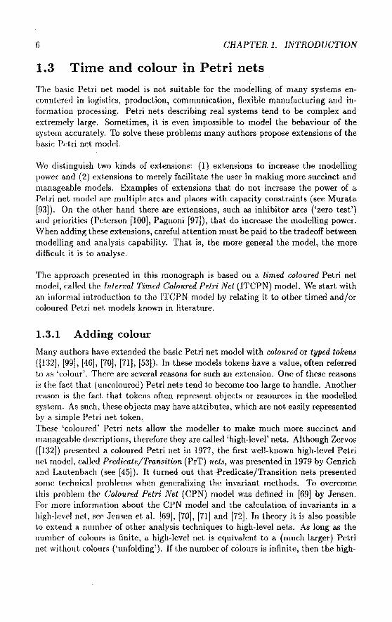
1.3.1 Adding colour
Many authors have extended the basic Petri net model with coloured or typed tokens ([132], [99], [46], [70], [71], [53]). In these models tokens have a value, often referred to as 'colour'. There are several reasons for such anextension. One of these reasons is the fact that (uncoloured) Petrinets tend to become too large to handle. Another reason is the fact that tokens often represent objects or resources in the modelled system. As such, these objects may have attributes, which are not easily represented by a simple Petri net token .. These 'coloured' Pctri nets allow the modeHer to make much more succinct and manageable descriptions, therefore they are called 'high-level' nets. Although Zervos ([132]) presented a coloured Petri net in 1977, the first well-known high-level Petri net model, called Predicate/Transition (PrT) nets, was presented in 1979 by Genrich and Lautenbach (see [45]). It turned out that ·Predicate/Transition nets presented some technica] problems when generalizing the invariant methods. To overcome this problem thc Co/oured Petri Net (CPN) model was defined in [69] by Jensen. For more information about the CPN model and the calculation of invariants in a high-level net, sec Jensen et al. [69], [70], [71] and [72]. In theory it is also possible to extend a numher of other analysis techniques to high-level nets. As long as the number of colours is finite, a high-level net is equivalent to a (much larger) Petri net without colonrs ('unfolding'). If the number of colours is infinite, then the high-

1.3. TIME AND COLOUR IN PETRINETS 7
level net is equivalent to a basic Petri net with infinitely many places and transitions. Allowing an infinite number of colours results in a modelling power equivalent to a Turing machine for which many questions are undecidable (see Peterson [99]), but on the other hand, Church's thesis implies that the Turing machine is the most powerful model of computation (Wood [129]).
Our ITCPN model is a successor to the DES model developed by Van Hee, Somers and Voorhoeve ([53]). Like in the other high-level net models, a colour is attached toeach token. Each place has a type (a set of colours) and tokens in a place have a colour (value) belonging to the corresponding type. The number of tokens produced by the firing of a transition, and their values (colours), may depend upon the values (colours) of the tokens consumed. Insteadof using are inscriptions, like in CPN, we use fundions to describe the relation between the set of consumed tokens and the set of produced tokens. Note that, unlike in CPN, the enabling of a transition does not depend upon the values of the tokens to be consumed.
1.3.2 Adding time
The forma! properties of 'Time' have attracted the attention of many philosophers, physicists and mathematicians (Benthem [14])·. Time is an important aspect of all discrete dynamic systems. There are several ways to deal with this timing aspect. First, one has to decide whether time has to be quantified. If time is not quantified, the model can only be used to reason about qualitative temporal properties, like liveness, mutual exclusion, deadlock, fairness, etc. We decide to quantify time, because only then, it is also possible to express quantitative temporal properties, like deadlines, activity durations, response times, delays, etc. If time is quantified, one has to decide whether time is implicit or explicit. In physics and mathematics, time has traditionally been represented as just another variable. Consicier for example first order predicate calculus, which can be used to reason about expressions containing a time variable, i.e. apparently there is no compelling need for explicit time. However, time plays a prominent part in the applications we consider, for we are interested in dynamic systems. Therefore, we decided to make time explicit (for reasons of convenience). This decision is based on the argument that the aspect of time is an important factor in the systems we want to consider, and the modelling effort is reduced considerably by adding explicit time constructs.
The basic Petri net model is not capable of handling quantitative time. The introduetion of high-level nets allowed people to quantify time in an implicit manner, i.e. time is represented by the value or colour of a token. In this case, we have to model a global doek using a. place connected to every transition. This placc contains one token, whose value represents the current time. Since this is rather cumbersomc, many authors have proposed a Petri net model with explicit quantitative time (e.g. [133], [108], [89], [82], [53], [113]). We call these models Timed Pctri Net (TPN) models.

8 CHAPTER 1. INTRODUCTION
There are a lot of ways to introduce the concept of time into the basic Petri net modeL In essence, there are two things one has to decide on: (1) the location of the time delays and (2) the type of these delays.
The location of the time delays
When introducing time into the basic Petri net model, we have to assign time durations ( delays) to certain activities in the net. The literature on timed Petri nets describes many 'locations' in a Petri net which may be used to represent time. Zuberek ([133]) associates a (fixed) delay with the firing time of a transition. When a transition fires, the enabling tokens are consumed and withheld for some time before the tokens appear in the output places. Since the firing of a transition takes some time, this is called 'two-phase' firing. Sifakis and Wong propose models where time is associated with places, so that tokens arriving in a place are unavailable for a specified period ([114], [128]). Most authors propose a model where time is associated with the enabling time of a transition (e.g. [41], [92], [82], [81]). Each transition in such a timed Petri net must remain enabled for a specified time before it can fire. In these models, firing is an atomie action, i.e. firing takes no time. Some authors use two timing mechanisms (at different locations). An example of such mixture is the model proposed by Razouk and Phelps in [109], where time is associated with the firing of transitions and the enabling of transitions.
We use a rather new timing mechanism where time is associated with tokens. This timing concept has been adopted from Van Hee, Somers and Voorhoeve ([53]). In our ITCPN model we attach a timestamp to every token. This timestamp indicates the time a token becomes available. The enabling time of a transition is the maximum timestamp of the tokens to be consumed. Transitions are eager to fire (i.e. they fire as soon as possible), therefore the transition with the smallest enabling time will fire first. lf, at any time, more than one transition is enabled, then any of these transitions may be 'the next' to fire. This leads to a non-deterministic choice if sevcral transitions have the same enabling time. Firing is an atomie action, thereby producing tokens with a timestamp of at least the firing time. The difference between the firing time and the timestamp of such a produced token is called the firing delay. Associating time with tokens is the logkal choice for high-level Petri nets, since the colour is also associated with tokens. We will show that our timing concept is very expressive and allows for elegant semantics.
The type of the time delays
Desides the location of the delay, we also have to decide on the type of delay. There are three alternatives: fixed delays, stochastic delays or delays specified by an interval. We also have to decide whether we use a discrete or continuous time domain. Neady all TPN models use a continuons time domain (JR+ U {0} ), so do we.

1.3. TIME AND COLOUR IN PETRINETS 9
Petrinets with fixed (deterministic) delays have been proposed in [133), [108], [113] and {53]. They allow for simple analysis methods but are not very expressive. In real discrete dynamic systems the duration of most activities is variable, because the duration of an activity often depends on external influences. Consider for example the time it takes to transport goods from a production unit to the central warehouse, this t.ransportation time depends on traflic jams, the weather, the mood of the driver, etc. Clearly, a fixed delay is inappropriate for the modelling of the duration of such an activity.
One way to model this variability, is to assume certain dela.y distributions, i.e. to use a timed Petri net model with delays described by proba.bility distributions. These nets are called stochastic Petri nets. Many stochastic Petri net models have been developed, most of them are used for the performance evaluation of protocols, manufacturing systems, etc. Two widespread modelsof this type are the SPN model by Florin and Natkin ([41]) and the GSPN model by Ajmone Marsan et al. ([82]). In nearly all stochast ie TPN models, time is in transitions and the enabling time of such a transition is specified by some distribution. The choice of such a delay distri bution is often difficult and subject to errors, thus yielding a crude approximation which appears to be exact. Analysis of stochast ie Petri nets is possible (in theory ), since the reachability graph can be regarded, under certain conditions, as a Markov chain or a semi-Markov process. However, these conditions are severe: all firing delays have to be sampled from an exponentlal distrihution or the topology of the net has to be of a special form (Ajmone Marsan et al. [81)). Since there are no general applicable analysis methods, several authors resorted to using simulation to study the behaviour of tbe net. Another problem is the fact that the delays of two activities may be dependent. When modelling these activities by separate transitions, the delays are assumed to be independent, this may lead to incorrect results.
To avoid these problems, we propose delays described by an interval specifying an upper and lower bound for the duration of the conesponding activity. On the one hand, interval delays allow for the modelling of variabie delays, on the other hand, it is not necessary to determine some artificial delay distri bution (as opposed to stochastic delays). Instead, we have to specify bounds. These bounds can be used to verify time constraints. This is very important when modelling time-critica! systems, i.e. reai-time systems with 'hard' deadlines. These hard (real-time) deadlines have to be met for a safe operation of the system. An acceptable behaviour of t.he system depends not only on the logica! correctnessof the results, but also on the time at which the results are produced. Examples of such systems are: reai-time computer systems, process controllers, communication systems, flexible manufacturing systems and just-in-time manufacturing systems.
To our knowledge, only one other model has been presented in litera.ture which also uses delays specified by an intervaL This model was presenteel by MerJin in

10 GRAPTER 1. INTRODUCTION
[89] and [90]. In this model t.he enabling time of a transition is specified by a minimal and a maximal time. Another difference with our model is the fact that Merlin's model is not a high-level Petri net model because of the absence of typed ( coloured) tokens. Compared to our model, MerJin 's model has a rather complex forma! semantics, which was presented in [16] by Berthomieu and Diaz. This is caused by a redundant statespace (marking and enabled transitions are represented separately) and the fact that they use a relative time scale and allow for multiple enabledness of transitions. An additional advantage of our approach is the fact that our semantics closely cortespond to our intuitive interpretation of the dynamica! behaviour of a timed Petri net. We will motivate these statements in due time.
1.4 Analysis of timed colonred Petri nets
In the previous section we established the fact that Petri nets are appropriate for the modeHing of discrete dynamic systems, provided that a Petri net model extended with time and colour is used. Based on this observation, we proposed the ITCPN model. In essence, the modelling process serves two purposes. First of all, the model is used as a 'blueprint' of the system under consideration, e.g. the design of a new system or a plan which describes improvements. Secondly, models are used to analyse certain aspects of a system, e.g. the performance, efficiency or correctness of a system. Sirree analysis is often the main goal of model building, we have to supply suitable analysis methods. ln this section we start with a survey of existing analysis methods_ for timed and/or coloured Petri nets to illustrate that none of these methods (entirely) suits our purpose. This has been an incentive to develop new analysis methods. Therefore, thc co re of this monograph is directed towards the analysis of interval timed coloured Pet.ri nets.
1.4.1 Currently used analysis methods
A lot of analysis techniques have been developed in the area of purePetri net theory. Most of them are based on the basic Petri net model. Ma.ny of these techniques have been extended to analyse high-level Petri nets, for exa.mple reacha.bility gra.phs and invariants. Reeall that as long as the number of colours is finite, a high-level net can be 'unfolded' into an equivalent, but much la.rger, Petri net without colours. The unfolding of nets has been stuclied to see how the analysis md.hods for high-level nets should work. For the moment, however, it is only possible to use these methods for relatively small systems and for selected parts of larger systems. An cxample of such a method is the creation of a reachability graph for high-level nets. Because of the explosion of the number of states, these graphs tend to become too large to analyse. Several reduction techniques have been proposed to deal with this problem. None of them gives a satisfactory solution (see Jensen [71]).

1.4. ANALYSIS OF TIMED COLOURED PETRINETS 11
Another analysis technique available for high-level Petri nets is the generation of place and transition invariants. These invariants are used to derive and prove properties of the modelled system. A place invariant (P-invariant) is a weighted token sum, i.e. a weight is associated with every token in the net. This weight is based on the location (place) and the value (colour) of the token. A place invariant holds if the weighted token sum of all tokens remains constant during the execution of the net. Transition invariants (T-invariants) are the duals of place invariants and the basic idea behind them is to find firing sequences with no effects, i.e. firing sequences which reprod\.\ce the initia! state. Some analysis techniques have been developed to calculate these invariants automatically (see Jensen [71]). These techniques have a number of problems. For large nets with a lot of different colours, it is hard to compute these invariants. Usually there are infinitely many invariants (a linear combination of invariantsis also an invariant), therefore it is difficult to distill the interesting ones. However, there is a more promising way to use invariants. If the user supplies a number of invariants, it is easy to verify these invariants totally automatically. If an invariant does not hold, it is relatively easy to see how the Petri net (or the invariant) should he modified. The latter approach does not solve the problem that applyiilg invariants requires a lot of training.
The addition of time to the basic Petri net model resulted in a lot of new and interesting techniques to analyse the dynamic behaviour of a system. Literature on this subject reflects the fact that the study of timed Petrinets developed a.long two separate lines.
The first line concentrates on the verification of dynamic properties. Most of the methods developed along this line arebasedon nets with deterministic delays. There are several methods to calculate upper and lower bounds for the cycle time of a timed Petri net ([113], (108], [107], [93]). The cyde time is a criterion for the performance of the system. For a specific class of deterministic timed Petri nets, the so-called Timed Event Graphs, the exact cycle time can he computed quite efficiently, see Rama.moorthy and Ho IJ07] and Cbretienne [31]. Other researchers analyse deterministic timed Petri nets by building the reachability gra.ph (Zuberek [133]). Although this requires a lot of computing effort, such a. graph can he used to answer a variety of questions. A serious drawback of these methods is the fact that in many rea.l systems thc activity durations are not fixed, i.e. they vary because of disturbances a.nd othcr interferences. Assuming deterministic delays often results in inaccurate results.
The second line concentrates on the performance evaluation of timed Petri nets by means of analysis of the underlying stochastic process. Instead of assuming deterministic activity durations, an attempt is made to capture the essence of a system by probabilistic assumptions. These probabîlistic assumptions often includc the distribution of the delays in the net. In ncarly all stochastic TPN modcls a stochastic variabie is associated with evcry transition. This stocha.stic variabie expresses the dela.y from the enabling to the firing of a. tra.nsition, i.e. the ena.bling

12 CHAPTER 1. INTRODUCTION
time. For analysis reasons, the distribution of these stochastic variables is assumed to be negatively exponential. Molloy showed that, due to the memoryless property of the exponential distribution, such a stochastic TPN is isomorphic to a continuons time Markov chain ([92]). This allows for analytica! methods to analyse the dynamic behaviour of a system, this way it is possible to calculate performance measures, e.g. the average waiting time or the probability of having more than five tokens in a specific place. Several other stochastic TPN models have been suggested ([82], [41], [80], [128], [64]). Consicier for example, the Generalized Stochastic Petri Net (GSPN) model developed by Ajmone Marsan et al. ([82], [81], [83]). A GSPN has two types of transitions: 'timed' transitions and 'immediate' transitions. A timed transition has an exponentially distributed enabling time, an immediate transition has an enabling time of zero, i.e. an immediate transition fires the moment it becomes enabled. Many authors give conditions for the topology of the net or the distribution of the delays such that analysis of the underlying stochastic process is possible (e.g. Ajmone Marsan et al. [81], [80]). In general these conditions are quite strong. Moreover, for real problems, the state space of the conesponding continuons time Markov chain tencis to be too large to analyse.
To our knowledge, only one analysis method has been presented for Petri nets with interval timing. This method was presented by Berthomieu et al. in [17] and [16] and uses Merlin's timed Petri nets ([89]) to describe the system. The method generates a reachability graph where nocles represent state classes instead of states. This approach is more or less related to one of the analysis methods presented in this monograph.
Only a few analysis methods have been developed for timed and coloured Petri nets, this resnlts from the fact that there are only a limited number of Petri net models having coloured tokens and some explicit time concept. In Lin and Marinesen [76] a.nd Zenie [131 J stochast ie high-level nets are proposed. A high-level Petri net model with deterministic dela.ys was presented by Van Hee et al. in [53]. A similar extension of the CPN model was proposed by Jensen in [71]. Note that a deterministic delay cicpending upon the colour of a token is sufficient to approximate any stochastic delay distribntion, since coloured tokens allow for the generation of pseudo-random numbers, which can be used to sample delays fora specific distribution, see Shannon [112] or [9]. A straightforward way to analyse the dynamic behaviour of such a net is simulation.
1.4.2 Analysis methods based on the ITCPN model
Although Petri net theory is rich in analysis methods, only a few of the methods are suitable for the analysis of the temporal behaviour of a timed coloured Petri net. Moreover, the methods nsed for the analysis of the dynamic behaviour of a system represented by a timed colonred Petri net suffer from computational problems. This is onc of the rea.sons, simulation is the most widely used technique to analyse nets

1.4. ANALYSIS OF TIMED COLOURED PETRINETS 13
which represent complex discrete dynamic systems.
The ITCPN model devia.tes from existing models, because delays are specified by an interval rather than deterministic or stochastic delays. If we choose a distribution for each delay interval (e.g. a uniform or beta distribution), then we are able to simulate an ITCPN. Although simulation is a very powerful tooi to analyse discrete dynamic systems, it is certainly not a panacea for answering all relevant questions. For example, simulation cannot be used to prove eertaio properties. This is one of the reasons, we have developed four analysis methods:
L Modified Transition Sysf.em Reduction Technique (MTSRT)
2. Persistent Net Reduction Technique (PNRT)
3. Arrival Times in Conflict Free Nets (ATCFN)
4. Steady State Performance Analysis Technique (SSPAT)
As said, these analysis methods are based on the ITCPN model.
The MTSRT metbod can he applied to any kind of ITCPN. This metbod generates a reduced reachability graph. In an ordinary reachability graph, a node corresponds to a state. To calculate such an ordinary reachability graph, we start with an initia! state, say s. For this state s, we obtain 'new states'. These are the states reachable by firing a transition in state s. New states are connected to $ by a directed are. For each new state, say s1
,
connected tos, we obtain the states readutbie by firing a transition in state s1, etc.
Repeating this process resttlts in a graph representation of the reacl1able states. Even for simpleexamples these graphstend to be very large (generally infinite). The MTSRT method proposes a number of reductions, resulting in a reduced reachabilily graph. In such a graph a node corresponds to a set of states, called a state class, instead of a single state. To generate a graph representation of these state classes, we use a modified model, where a time-interval is associated with a token rather than a timestamp. We already mentioned a more or less related analysis metbod proposed by Berthomieu, Menache and Diazin [17] and [16]. This metbod is based on Merlin's timed Petri net model. Their analysis method also uses state classes, which are represented by a system of inequalities. Our MTSRT method uses a totally different approach to analyse a Petri net with inl.erval timing and is able to answer other types of questions. We will compare th<>ir method with om MTSRT method in due time.
The other methods can only be applied to a restricted set of interval timcd coloured Petri nets. The PNRT method and the SSPAT metbod can be applied to ITCPNs whose Ull
derlying net structure is a marked grnph, i.e. the number of input arcs and output arcsof every place is smallf'r than or f'qual to 1. Th!~ PNHT mdhod us!.'S the special

14 CHAPTER 1. INTRODUCTION
structure of such a net to create an even further reduced reachability graph. The SSPAT method calculates upper and lower bounds for the cycle time of a net. This is a generalization of the technique described by Ramamoorthy and Ho in [107]. The ATCFN method can be applied to conflict free nets, i.e. nets where the number of output arcsof every place is smaller than or equal to 1. This metbod produces upper and. lower bounds for the arrival time of the first token in a place using a polynomial-time algorithm.
The analysis methods MTSRT, ATCFN and PNRT are outlined (in detail) in this thesis. Fora description of the SSPAT method, see Van der Aalst [2].
For complex practical problems, the MTSRT metbod is most appropriate, hecause it can be applied to arbitrary interval timed colonred Petri nets. The oonditions made by the other methods are often too restrictive. Furthermore, the MTSRT metbod is the only metbod able to answer questions irtvolving the colour of tokens. The PNRT, ATCFN and the SSPAT abstract from the token colours. However, there are application areas where these limitations are not restrictive. For example: the ATCFN metbod can be used to analyse project plans, and the PNRT method can be used for production planning with repetitive schedules.
A consequence of the flexibility of the MTSRT method, is the oomputational cffort rcquired to analyse a complex system. For practical problems, the 'reduced' reachability graph generated by the MTSRT method, tends to become too large to analyse. In most cases this is caused by a large and complex net structure and/or a large number of possible token colours. To deal with large colour sets, we propose techniques totranslate an ITCPN into an ITCPN with only one kind of tokens, i.e. the cardinality of each colour set equals 1. Such an ITCPN is called an Interval Timed Petri Net (ITPN). One can think of an ITPN as a specific kind of ITCPN with only one colour. Our aim, however, is to analyse interval timed coloured Petri nets. Therefore, we investigated suitable procedures for the translation of an ITCPN into an ITPN. There are two other reasons for ha ving the desire to translate an ITCPN into an ITPN. First of all, lTCPNs with only one kind of tokens allow for several structural an.alysis techniques developed for uncoloured nets (see Murata [93]). Another reason is the fact that, at the moment, our analysis software only supports the analysis of uncoloured ITCPNs. Since we are able to (automatically) translate an ITCPN into an ITPN, we can analyse ITCPNs indirectly,
We distinguish three ways totranslate an ITCPN into an ITPN:
unfold The first way is to translate the ITCPN into an equivalent ITPN is to use a construction similar to the one presented in Peterson [99] and Genrich [44]. Such a construct ion, often referred to as 'unfolding', is only possihle if the number of colours is finite. The construction maps each place (transition) in the ITCPN intoasetof places (transitions) in the constructed ITPN. If there

1.4. ANALYSIS OF TIMED COLOURED PETRINETS 15
are many different colours, the size of the constructed ITPN becomes very . làrge. Therefore, this approach cannot be applied to large practical examples.
uncolour Another way to reduce the ITCPN into an ITPN is to discard the colours, to a certain extent. Each place in the ITCPN corresponds to exactly one place in the ITPN. If a transition in the ITCPN always produces the same number of tokens for every output place, then this transition also corresponds to exactly one transition in the ITPN. The lower bound (upper bound) of the delay of a token produced by a transition for a specific output place in the ITPN, corresponds to the smallest (largest) lower bound (up per bound) of all possi bie delays assigned to this place by the transition in the ITCPN. If the number of tokens produced by a transition in the ITCPN depends on the valnes of the consumed tokens, then this transition corresponds to a set of transitions in the ITPN. In practice the cardinality of this set is smal!. Therefore, this construction produces an ITPN of about the same size. Consicier for example, a transition t with two output places o1 and o2 • Assume that: if t fires, it produces one token, either for place o1 or for place o2 (cl epending u pon the valnes of the consumed tokens). In the corresponding uncoloured net t is replaced by two transitions t1 and t2• Both transitions consume tokens from the input places of t. Transition t 1 produces a token for place o1 and transition h produces a token for place D2·
Clearly some information is lost during this construction. However, it is still possible to derive useful properties for the ITCPN. For instance, if the ITPN is K-bounded (deadlock free), then the ITCPN is also K-bounded (deadlock free), and upper and lower bounds for the cycle time of the ITPN arealso valid upper and lower bounds for the ITCPN. Often it is possible to prove certain properties for an ITCPN by analysing the conesponding ITPN, for example, it is possible toprove that certain deadlines are met.
refine The third way to use an ITPN to analyse an ITCPN is a mixture of tbc previous two. This hybrid approach works in two steps, first, for each place, the set of possible colours is partitioned into a number of colours sets, then the net is unfolded into an ITPN. A place in the ITCPN is mapped into a set of places, the cardinality of this set depends on the partitioning. In other words: first, we transform the ITCPN into an ITCPN with less colours and more places, then we remove the colours.
Consicier for example an ITCPN with tokens representing machine jobs. Thc service time of a job depends on the colour of the token, i.e. i is a.ttributes. A job can have a large number of attributes, like weight, si ze, operations required, etc. In this case it is possible to partition the set of possible jobs into two meaningful classes: 'small' jobs and 'large' jobs. Based on this partitioning it is possible to derive upper and lower bonnels for the service time of small (large) jobs. When unfolding the ITCPN into an ITPN, each place containing jobs is mapped into two places, one for small jobs ancl one for large jobs. The transitions connected to these places are also duplica.ted.

16 CHAPTER 1. INTRODUCTION
This way it is possible to derive tight bounds for the behaviour of the ITCPN without having an 'explosion' in the size of the net. Preferably, this approach is supported by a tooi in an interactive way.
This monograph describes the last two approaches. These approaches are attractive, because they can be applied to large coloured and timed Petri nets, as opposed to nearly all other analysis methods. Note that this is a direct consequence of the fact that we use interval delays rather than deterrninistic or stochastic delays.
1.5 ExSpect
The practical use of the ITCPN modeland related analysis methods highly'depends upon the availability of adequate computer tools. To facilitate the creation, storage and adaptation of these models, we use a specification language to represent these models. We already mentioned that a forma! specification is a precise and structured description of a system, expressed in a language having a syntax and semantics. We use the Petri net based specification language ExSpect ([53], [55], [52], (56], [51J, [57], [8], 17]). This language has been developed at Eindhoven University of Technology, and is supported by a software package also called ExSpect (see Somers et al. [54], [91). We use ExSpect for the forma! specification of a restricted class of interval timed coloured Petri nets. There is a straightforward relation between this specification language and the ITCPN model. In fact, the semantics of ExSpect are given in termsof a timed coloured Petri net model (see Van Hee et al. [53]). The language ExSpect consistsof two parts: a functional partand a dynamic part. The functional part is used to define types and functions needed to describe the operations on the value of a token. The type system consists of some primitive types and a few type constructars to define new types. A 'sugared lambda calculus' is used to define new fundions from a set of primitive functions. ExSpect is a 'strongly typed' language sirree it allows all type checking to be clone statically. A strong point of the language is the concept of type variables: it provides the possibility of polymorphic functions. The dynamic part of ExSpect is used to specify a networkof transitions and places, and therefore, the interaction structure of a system. The behaviour of a transition, i.e. the number of tokens produced and their values, is described by functions. The language also has a hierarchical construct called system. A system is a subnet, i.e. an aggregate of pi aces and transitions and (perhaps) subsystems. The system concept supports both top-down and bottorn-up design. A system can have a number of parameters. As a result, a system can be customized or fine-tuned for a specific situation. This way it is possible to define gencric system specifications, that are easy to reuse.
The software package ExSpect (EXecutable SPECification Tooi) is a workbench based on the specification language ExSpect. This workbench is made up of a number of software tools, figure 1.2 shows the set of tools of ExSpect. These tools

1.5. EXSPECT
design interface
analysis tool
(lAT)
type checker
runtime interface
interpreter
extern al fooif----t appl.
Figure 1.2: The tooiset ExSpect
17
are integrated in a shell, from which the different tools can be started. The design interface is a gra.phical mouse driven editor, which is used to construct or to modify an ExSpect specifica.tion. Such a specification is stored in a souree file (module). This souree file is checked by the type checker for type correctness. If the specification is correct, then the type checker generates an object file, otherwise the errors are reported to the design interface. The interpreter uses the object file to execute a simulation experiment described by the corresponding ExSpect specification. This interpreter is connected to one or more 1'tmtime interfaces. These interfaces allow one or more users to interact with the running simulation. lt is also possible to interact with some external application, for example presentation software.
Recently we added an analysis tool, called the ITPN Analysis Tooi (lAT), to ExSpect. This tooi translates a specification into an ITPN that is analysed using the methods described in this monograph, i.e. the MTSRT, PNRT and ATCFN analysis methods. The tooi also allows for more traditional kinds of analysis such as thc generation of P and T-invariants. This way we offer three kinds of analysis: simulation, 'structural analysis' (invariants) and 'interval analysis' (MTSRT, PNRT, ATCFN). This observation reveals an interesting issue: a forma] specification can be used as a 'blueprint' of the system, which allows for various kinds of analysis. This is very convenient, since it preventsus from having to remodel thc system every time we want to use another analysis technique. Thcreforc, wc are also intcrestc<l in supporting other analysis techniques, e.g. Markovian anàlysis, queueing nctworks, linear programming, etc.

18 GRAPTER 1. INTRODUCTION
1.6 Application to logistics
High-level Petri nets have been used in rnany application areas: ftexible rnanufacturing, computer architecture, distributed inforrnation systerns, protocols, etc. In [72] there are a number of papers descrihing applications of high-level nets. We have used ExSpect in various application dornains, e.g. queueing systems ([3]) and flexible rnanufacturing ([7]).
However, our main interest is in the modelling and analysis of logistic systerns ([4], [5], [8], [6]). This interest sterns from three reasons: First of all, timed coloured Petri nets are an appropriate way to describe logistic processes. Note, that a logistic systern is composed of physically distributed subsysterns with a rather complex interaction structure, i.e. a typ i cal exarnple of a discrete dynamic system. Secondly, recent developrnents in the field of logistics have cornplicated the management of the logistic processes, e.g. the integration of logistic activities often results in complex control problems. Therefore, there is a need for an integrated framework for the rnadelling and analysis of logistic systems. Thirdly, we participate in a project called TASTE (The Ad vaneed Studies of Transport in Europe). The goal of this project is to develop a tooi to enable nonprogramrners to model and analyse strategie problems in the field of interindustrial logistics. TASTE uses ExSpect tomodeland analyse the flow of goods at an aggregated level in and between, production, assernbly, distribution and transport (see [6]).
The TASTE project faced the fact that research in the field of logistics developed along two separate lines. The first line concentrates on solving mathematica! problerns related to logistics. Investigations in this area are part of a discipline called operations research. Often thc problern statement is simplified to allow for analyticaJ solutions. This is the rea.'>On that rnany n'sults in this area are not generally applicable and require an expert consultant. Examples of this line are the application of queueing networks to scheduling problems and the application of linear prograrnrning to transport planning. Although these analysis rnethods help us gain insight in the problern, they can only be applied in rather specific situations. Moreover, some of the results reported in this area describe techniques for problems that do not even exist in practice. The secor1d line of research concentrates on practicallogistic problerns. The results are often qualitative and informal. The approaches used in this area are mainly discipline oriented, i.e. they focus on a specific aspect of logistics. Examples are the research on customer service, storagc equipment, communication facilities (EDI),
· persounel requirements, etc. Neither of these lines has lead to an integrated framework to model and analyse logistic systems. This is the reason this monograph outlines concepts and tools to facilitate the modeHing and analysis of reallogistic problems. First, wc motivate our choice to use timed colonred Petri nets. We will do this by

L 7. OTHER METHODS 19
showing that our Petri net model is able to represent typical logistic activities in a very convenient manner. Secondly, we present a 'systems view of logistics' to structure complex logistic systems. Based on a taxonomy of the flows in a logistic system, we descri he a systematic approach to the rnadelling of logistic systems. This approach can he used as a stepping-stone to the development of a comprehensive 'reference model' of logistics. Such a reference model is a representation of an idealized organization, defining the tasks of the logistic components as well as the interaction between these components (see Biemans et al. [19], [21]). Thirdly, based on our 'systems view of logistics' we have developed an ExSpect library of predefined system definitions. These system definitions are parameterized building blocks representing typicallogistic activities. There are about 20 of these huilding blocks including a production unit, a distribution centre and a transport system. It is our belief that many practical logistic systems can be modelled using these huilding blocks. Modelling in termsof building blocks is supported by software (ExSpect) and the modeHing process results in a specification that can be analysed using simulation and the analysis methods already mentioned.
Our approach is intentionally abstract. Therefore, we focus on the main logistic functions (e.g. transport, demand, supply, production and stock holding) and ignore aspects, like administration, safety, personnel, etc. Moreover, sometimes we also abstract from the physical reality, i.e. we are not interested in the actual layout of a logistic system, mechanica! aspects, communication protocols, etc.
1. 7 Other methods
We use a Petri net based approach, this is only one of the many approaches which have been developed tomodeland analyse discrete dynamic systems. We distinguish three main directions:
• simulation techniques
• diagramming techniques
• forma! techniques
Simulation is one of the most powerful techniques to analyse a complex system. Advantages of simulation are: easy to use, flexible, availability of tools. Another important advantage of simulation is that it helps the analyst to understand and to gain a feel for the system. In a way, simulation is similar to the debugging of a program, in the sense that it can reveal errors of a (simulation) model. In practice, however, simulation is never sufReient to ·prove the correctness of the system. There are two kinds of simulation tools: si mulation languagcs and specific sim u lation packages. Simulation languages, such as SIMVLA (Dahl and Nygaard [33]) and SIMAN (Pidd [103]), are flexible but lack sufficient support of the modelling process, e.g. a graphical editor, analysis tools, etc. Simulation packages are often application

20 CHAPTER 1. INTRODUCTION
specifk. Examples in the field of manufacturing are SIMFACTORY and TAYLOR ([103]). These packages are easy to use and support anirilation. The fact that they are tailored towards a specific application makes them infiexible. Note that, although ExSpect is a specification language, it can heusedas a si mulation language which can be tailored towards a specific domain by creating reusable systems, i.e. it is possible to use libraries of user-defined building blocks. The application of these building blocks is quite easy, because they can be used in a completely graphical manner.
There are several frameworks based on diagramming techniques. These frameworks use a graphical language to describe data flow, control flow, etc. The graphical nature of these frameworks makes them ea.sy to use. Examples are SADT (Marca and McGowan [79]), ISAC {Lundeberg et al. [78]) and DFD (Ward and Meilor [121]). Most of these frameworks incorporate techniques to describe the data structure, for example the entity-relationship model (Chen [29]). The result of using such an approach is an informal description, that does not allow for quantitative analysis. Another drawback of these techniques is that they Jack a concept to quantify time which makes it very difficult to model reai-time constraints.
Forma/ methods to model (specify) and to analyse discrete dynamic systems are, at this point, mainly under development in the academie world. Some of these methods are slowly gaining industrial a.cceptance. We distinguish 6 directions:
• queueing networks
• finite state machines
• model oriented specifications
• process algebras
• temporallogic
• Petrinets
We wiJl review these forma! methods, without claiming to give a complete survey.
A queueing network (Ajmone Marsan et al [83]) is a system of interconnected queues in which customers ei reu late, arrive or leave. Queueing networks have become <1uite popular in the field of performance evaluation. The main reason for this popularity is due to the product form solution, that holds for a restricted class of queueing networks (see Baskett et al [13]). This restricted class allows for the analytica! solution of all sorts of performance measures. Nevertheless, several practically important features, like syn('hronization, blocking and the splitting of customers can usually not he modelled in such a way that the model still has the product form solution (sec Ajmone Marsan ct al. [83]). For non-product form queueing networks there are approxima.tiv<' methods of analysis available, but these

1. 7. OTHER METHODS 21
are notgenerally applicable and require an expert consultant. Therefore, fora more detailed analysis of queueing networks, simulation is practically unavoidable.
The finite state machine is a restrietion to the classica! model of theoretica! computer science (Hopcroft and Uilman [66]). A finite state machine can he modelled using is a state transition diagram (Davis [34]). At any moment the machine is in a certain state. In response to an input the machine generates an output and changes state. Statecharts (Harel [48]) represents a generalized formalism based on finite state machines. In statecharts, the normal state transition diagram is enhanced with hierarchical and compositional features. Aithough a supporting tooi, called 'statemate', has been deveioped, this method cannot he used to modellarge reai-time systems because of the absence of facilities to model data structures and quantitative time.
VDM (Jones [73]) and Z (Spivey [116]) are model oriented sper:ification languages. These methods have been found useful for the specification of large commercial systems, but are weak in their ability to deal with concurrency and real-time. Furthermore, these languages do not allow for quantitative analysis, the emphasis is on specification rather than analysis.
Process algebras, such as CSP (Hoare [63]), CCS (Milner [91]) and ACP (Bergstra and Klop [15]), are well suited for the modelling of parallel and concurrent behaviour. They are however poor in their capabilities to specify data structures and operations. There are several algebraic specification languages hased on one of these process algebras, e.g. LOTOS (Brinksma [27], [26!) and PSF (Mauw and Veltink [86]). These languages have constructs to handle data structnres, modularization and parameterization. Moreover, several process algebras have heen extended with timing constraints, for example timed-CSP (Reed and Roscoe [IJ 0]), CCSR ( Gerber and Lee [47)), ACPp (Baeten and Bergstra [12]) and Timed LOTOS (Bolognesi ct al. [23]).
Temporal logic (Pnueli [104]) is a branch of modal logic. GeneraJly, a number of temporal operators are introduced, for example 0 (henceforth) and 0 { eventually ). Various types of semantics can he given to the temporal operators depending on whether time is linear or branching, time is quantified, time is implicit or explicit, time is local or global, etc. A temporal logic is called a reai-time temporal logic if time is quantified. Metric Temporal Logic (Koyrnans [75]) is a reai-time temporallogic with an implicit time construct. For example, the forrnula A-> 0 9 B means that: if A occurs, then eventually within 3 time units B must occur. Reai-Time Temporal Logic (Ostroff [95]) bas an explicit time (doek) variabie t. The previous formula can be expressed as follows: (A A t T) 0( 13 A t s; T + :J). An overview of existing frameworks in temporallogic is givcn by Ostroff in [96]. Temporal logic is suitable for descrihing (tempora!) properties of a system. Disadvantages are the fact that temporal logic is diffîcult to learn a.nd spccifications
22 CHAPTER 1. INTRODUCTION
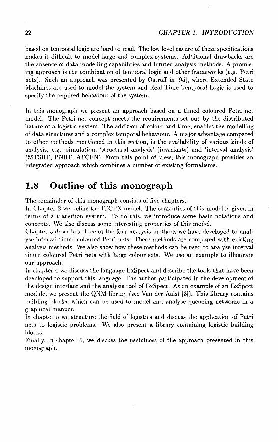
based on temporallogic are hard to read. The low level nature of these specifications makes it difficult to model large and complex systems. Additional drawbacks are the absence of data modeHing capabilities and limited analysis methods. A promising approach is the combination of temporallogic and other frameworks (e.g. Petri nets). Such an approach was presented by Ostroff in [95], where Extended State Machines are used to model the system and Real-Time Temporal Logic is used to specify the required behaviour of the system.
In this monograph we present an approach based on a timed colonred Petri net model. The Petri net concept meets the requirements set out by the distributed nature of a logistic system. The addition of colour and time, enables the modeHing of data structures and a complex temporal behaviour. A major advantage compared to other methods mentioned in this section, is the availability of various kinds of analysis, e.g. simulation, 'structural analysis' (invariants) and 'interval analysis' (MTSRT, PNRT, ATCFN). From this point of view, this monograph provides an integrated approach which combines a number of existing formalisms.
1.8 Outline of this monograph
The remainder of this monograph consists of five chapters. In Cha.pter 2 we define the ITCPN model. The semantics of this model is given in terms of a. transition system. To do this, we introduce some basic notations and conccpts. We also discuss some interesting properties of this model. Chapter 3 describes three of the four ana.lysis methods we have developed to analyse interval timed colonred Petri nets. These methods are compared with existing analysis methods. We also show how these methods can he used to analyse interval timed coloured Petri nets with large colour sets. We use an example to illustrate our approach. In chapter 4 we discuss the language ExSpect and describe the tools that have been developed to support this language. The author participated in the development of the design interface and the analysis tooi of ExSpect. As an example of an ExSpect module, we present the QNM library (see Van der Aalst [3]). This libra.ry contains building blocks, which can he used to model and analyse queueing networks in a graphical manner. In chapter 5 we structure the field of logistics and discuss the application of Petri nets to logistic problems. We also present a. library conta.ining logistic building blocks. Fina.lly, in cha.ptcr 6, we discuss the usefulness of the approach presenteel in this monograph.

Chapter 2
A timed colonred Petri net model
2.1 Introduetion
In this chapter we give a forma! definition of our ITCPN modeL This chapter also describes some fundamental concepts, such as behavioural properties and performance measures. Some of these concepts have been adopted from existing Petri net theory, others have been developed with the rest of this monograph in mind. The concepts described in this chapter are used throughout this monograph and so they are fundamental to a correct understanding of our approach.
PI
Figure 2.1: An interval timed coloured Petri net
In section 1.3 we already discussed tlw need for a timed a.nd colourcd Pctri net model. This is the reason we developed the Interval Timed Coloured Pet1·i Nel (ITCPN) model. . To illustrate this model we use an example. Figure 2.1 shows an ITCPN which comprises four places (p1 , TJ2, p3 and p4 ) and two transitions (t 1 and l 2 ). Transition t1 has two input places (p1 and p2 ) and onc> out put pi ace (p.t). Transition t2 also ha~ two input places (p2 and p:l) and onf' output pla('(' (JI,.}. At any moment, a placc

24 CHAPTER 2. A TIMED COLOURED PETRI NET MODEL
Figure 2.2: An ITCPN, t 1 and t2 are enabled
contains zero or more tokens, drawn as black dots. In the ITCPN model, a token has four attributes: an identity, a position, a value and a timestamp, i.e. we can use thc quartet (i, p, v, x) to denote a token in place p with value v, timestamp x and somc identification number i. Figure 2.2 shows the ITCPN in a. state with one token in Pt. two tokens in p2 and one token in p3 . In this example, the value of any token is a string, e.g. the token in placc p1 has a value !4B'. In thc state shown in figure 2.2, both transitions t 1
and t2 are enabled, because each of the input places of t1 and t 2 contains at least onc tokcn. Thc enabling time of t1 is the maximum timestamp of the tokens to be consumed, i.e. 3.0 (the maximum of 3.0 and 2.0). The enabling time of t 2 is 4.0 (the maximum of 2.0 and 4.0). Note that tokens on a place are consumed in order of their arrival (i.e. timestamps). Transitions are eager to fire, therefore t1 :lires at time 3.0. Firing t1 means consuming a token from place Pt ((l,p1, !4B',3.0)) and place P2 ( {2, p2 , t7 D', 2.0)) and producing a token for place p4 whose value may depend on Lhe values of the tokens consumed. In this case the value of the produced token is the concatenation of the values of the tokens consumed (i.e. !4BC D'). The delay of this token is between 0 and · 2. Figure 2.3 shows a state resulting from the firing of transition t1 in figure 2.2. In this case the delay of the token equals 1.25, however, any other va.lue between 0 and 2 would have been allowed. The identification of the new token is an arbitrary, but unique, number (in this case 5). In thc state shown in figure 2.3 only t2 is enahled. The enabling time of t 2 is 5.0 (the maximum of 5.0 and 4.0). Consequently, this transition fires at time 5.0. Transition t2 also concatenates two strings, i.e. t2 consumes a token from place P2 ((3,p2 ,'EF',5.0)) and place p3 ((4,p3,'GH',4.0)) and produces a token for place p4 (e.g. (6,p4 ,'EFGH',6.50)). Note that in this case the delay of the produced token is 1.5. F'igurc 2.4 shows a state resulting from the firing of transition t2 in figure 2.3. There are no transitions enabled in this state.

2.2. NOTATIONS 25
Pt
Figure 2.3: A state resulting from firing transition t 1
Pt
Figure 2.4: A state resulting from firing transition t2
The above example illustrates the dyna.mic beha.viom of an ITCPN. I t is, howcvcr, nearly impossible to give an informal explanation which is complete and unambiguous. Since an informal discussion of the meaning of interval timcd coloured Petri nets is likely to cause confusion, we give a forma! definition of the ITCPN model and the corresponding semantics in section 2.4. Because our formalisms are bascel on bag theory and transition systcms, wc start with some useful notations and a forma! definition of transition systems.
2.2 Notations
IN is thesetof natura! numbers including zero. Dl is thesetof reals. lt is convcnicnt to adjoin to lR two additional elem<'JÜs, oo and -oo ( not belonging 1.o Dl.) with Uw

26 GRAPTER 2. A TIMED COLOURED PETRI NET MODEL
order properties -oo < a < oo for any a E ll.. We 'extend' the addition operator for reals such that for all a E ll.: a + oo = oo + a = oo and oo + oo = oo. Similar conventîons hold for -oo. The expressions oo- oo and -oo + oo are undefined.
The Cartesian product of two sets A and B, denoted by A x B, is the set of all ordered pairs (a, b) with a E A and b EB. If x (a, b) E A x B then 1r1(x) a and 1r2(x) b. For n E IN, At,Az, .. ,An sets, x E At X Az x .. x An and iE {l, .. ,n}, 1r;(x) denot.es the ith component of x.
A binary relation R on a setS, is a subset of S x S. If Sa set and R Ç S x S then: R!l =I {(s,s) Is ES}, Rn = {(st, SJ) E s x s I 3.2ES( (sh Sz) ER A (sz, 83} E nn-l )}, for n > 0 and R* = {(si.sz) l3nEIN (sbsz) E nn} = UnEINnn, the reflexive and transitive dosure of R.
A partially ordered set, or just poset, is a pair (S, R} where Sisasetand Ra binary relation on S, which satisfies the following conditions:
'<lsES (s,s) ER v ••.• 2ES ((st, Sz} E R) A ( (sz, si) E R) ::} (si Sz)
((si.s2}ER) A ((sz,sJ)ER) =? ((st,SJ}ER)
( refiexi ve) ( antisymmetrie) ( transitive)
In general we denote a partîal ordering by and use an infix notation. We will adopt the notations St < Sz, St 2::: Sz, St > Sz for respectively St :5 s2 A St :f:. Sz, s2 :5 s~. s2 :5 s1 A s1 :f:. s 2 • A poset (S, is a linear ordering (total ordering), if and only if, for all St, sz E S: St :5 Sz or Sz :5 St.
Set operations are defined in the usual way. If A is a set, then #A is the number of elementsin A and P(A) is the powerset of A (the set of all subsets of A).
For A and B sets, A ---+ B denotes the set of all total functions from A to B and Af+ B denotes the set of all partial fundions from A to B.
If f E Af+ B then dom(!) is the domain of f and rng(f) = {f(x) I x E dom(!)} is the range of f. If fa. function then fis also defined for X Ç dom(!): f(X) = {f(x) I x EX}.
f r X denotes the restrietion of a function to X ç dom(!), i.e. dom(! r X) X and for all x EX: ft X(x) = f(x).
We use the lambda nota.tion or the 'set notation' to define functions, i.e. a function f ÀxEdom(J)!(x) = {(x,J(x)) I x E dom(!)}.
Note that the set notation of a function allows fora number of set operations. If ft, fz are functions, then:
#.ft #dom(JJ) .ft Ç fz iff dom(ft) Ç dom(fz) A '<lxEdom(JI) ft(x) = .fz(a:) ft\ h h r {a· E dom(ft) I x E dom(fz) :::} ft(X) =fAx)}

2.2. NOTATIONS 27
Furthermore, if ft, h fundions with disjoint domains then: ft Uh= {{x,y) I (x E dom(ft) A !1(x) = y) V (x E dom(h) 1\ h(x) = y)}
For a totally ordered set A and x,y E A: x min y (x max y) is the minimum (maximum) of x and y, i.e. if x $ y then x min y x (x max y y). If A is a totally ordered finite non-empty set, then min A is the mlnimal element of A and max A is the maximal element of A. If A = 0, then min A = oo and max A = -oo. If A Ç RU { -oo, oo} then min A (max A) is the supremum (infimum) of A. If A is not bounded below (above) then min A = -oo (max A = oo). Because of the completeness axiom for reals (see Depree and Swartz [36]), every subset of RU { -oo, oo} has a supremum and infimum. Sametimes we use an alternative notation to denote the minimum (maximum) of the range of a function f on a specified domain A: minxEAf(x) min{f(x) I x E A} and maxxeAf(x) = max{f(x) I x E A}. .
Intuitively a multiset is the same as a set, except for the fact that a multiset may contain multiple occurrences of the same element. A nother word for multiset is bag. Bag theory is a natura! extension of set theory (see Peterson [100]). A multiset, likc
a set, is a collection of elements over the same subset of somf' universe. However, unlike a set, a multiset allows multiple occurrences of the same element. A multiset boverA is defined by a function from A to IN, i.e. b E A-> IN. lf a E A then b(a) is the number of occurrences of a in the multiset b. IB( A) is the set of all multisets over A. We now introduce some operations on bags. Most of thc s<'t operators can be extended to bags in a rather straightforward way. Suppose A a set, b1, b2 E D3( A) and q E A.
q E b1 iff b1(q);:;: 1 b1 Ç bz iff '<taeA bt(a) $ hz(a) b1 bz iff b1 Ç bz A bz Ç b1 bt U bz = ÀaEA (bi( a) max b2(a)) bt n b2 = ÀaEA (bt(a) min b2(a)) b1 + bz = ÀaeA (bt(a) + b2(a)) b1 \ b2 ÀaEA ((bi{a) bz(a)) max 0) min(~) min{a E A I a Ebt} max(b1 ) max{a E A I a E bd #bt = :E bt(a)
aEA
(membership) ( inclusion) (equality) (union) (intersection) (sum) (difference) (minimum) (maximum) ( cardinality of a fini te hag)
We use square brackets to denote multisets by enumeration. Suppose A a set, n E IN and qo,ql, .. ,qn E A then [qo,q., .. ,qn] ÀaEA #{iE {O, .. ,n} I q, =a}. Consi<kr, for example, the following bags over the -domain IN: [1, 3], [ 1, 1, 1], [ 1, 2, 1, 2]. Note that [1, 2, 1, 2] and [1, 1, 2, 2] indicate the same bag. We u se [ J to denot.e the empty bag.
Although bags are a generalization of sets, we waut to he ahl<' to r<'pres<•nt l>ags

28 CHAPTER 2. A TIIviED COLOURED PETRI NET MODEL
as sets. This can be done by attaching a unique label to every element in the bag. An advantage of such a labelled bag is the fact that it is possible to identify single elements in a bag. In the rest of this monograph we assume that there is an infinite set of labels called Id, for example Id JN. More formally: we represent a finite bag b E IB(A) by a partial function sE Id f+ A with a finite domain. In order to be able to switch between the two types of representation, we introduce two conversion functions: SB and BS.
Definition 1 lf A is a set then wedefine SB E (Id f+ A) f+ E(A) and a BS E IB(A) f+ (Id f+ A) as follows. For any sE Id f+ A with a finite domain and for any finite bag b E IB(A), we have:
SB(s) = ÀaeA#{i E dom(s) I s(i) =a} SB(BS(b)) b
Function SB transforms a labelled bag into the conventional representation without labels. Note that several functions BS satisfying the condition VbElB(A)SB(BS(b)) = bare possible (' Axiom of Choice'). It is easy to verify that such a function exists, e.g. take one element from the bag and label it 1, take an arbitrary other one and label it 2, etc. For example, if A is a totally ordered set and ld = lN, then we may cicfine BS as follows. For any finite b E IB(A): BS(b) label(Id,b), where for any x ç ld:
{ 0 if b = [ l
label(X, b) = {(min X, min b)} U label(X \{min X}, b \[min b]) if b '# []
Iu the remaioder of this monograph we assume a given BS, i.e. a fixed function.
Definition 2 Two labelled bags over A, say St, s2 E I d f+ A, are equal if and only if the corresponding bags are equal, i.e. SB(s 1 ) = SB(s2).
If two labelled bags are equal, then there is an obvious bijeetion between the elemcnts. This is expressed by the following lemma:
Lemma 1 Let A be asetand St.S2 E hl f+ A. Then SB(st) = SB(s2 ) if and only if there exists a bijective function f E dom(s 1) -+ dom(s2 ) with:

2.3. TRANSITION SYSTEMS 29
Figure 2.5: Two equivalent labelled bags
Pro of. Let sbsz E Id f+ A.
(1) Assume that there exists a bijective f E dom(sl) ~ dom(s 2 ) with for all i E dom(s1 ): St(i) = sz(f(i)). Now we have to prove that S8(.5t) SB(sz). For any a EA: {iE dom(sl) I St(i) =a} {iE dom(sd I .s 2(f(i)) =a} and #{iE dom(st) I sz(f(i)) a}= #U E dom(sz) I sz(j) =a}(! is bijective). Hence, ÀaeA#{i E dom(st) I St(i) a} ÀaeA#{j E <lom(sz) I sz(j) =a}, i.e. SB(s1) SB(sz).
(2) Assume that SB( st) SB(s2). Now we have to prove that there exists a bijective f E dom( si)~ dom(s 2 ) with for all iE dom(si): .si( i)= s 2 (.f(i)). For a.ny a E A: #{iE dom(st) lst(i) =a}= #U E dom(.9z) I sz(j) a}, because SB(sl) = SB(s2 ).
If X and Y two arbitrary sets and #X = #Y, then there exists a bijective g E X -->
Y. Hence, for each a E A, there exists a bijective {u netion fa E {i E dom(s 1 ) I ,9 1 (i) a}~ {jE dom(sz) I sz(j) =a}. If all az E Aandat =f az, then dom(Ja 1 ) ndom(fa2 ) = 0 and rn.!J(Ja,) nr·ng(fa2 ) = 0. Consequently, f = UaeA!a is bijective and for all iE dom(., 1 ): st( i) s2{f(i)). 0
Figure 2.5 shows a bijective function f relating two equivaknt labelled bags. In this case, dom(!)= {1,2,3,4}, f(I) = 34, f(2) 43, .f(:J) = 7(i and .f(4) = 32.
2.3 Transition systems
To formalize the ITCPN model we have to attach a pr<'!'ÎRc meauing to interval timed coloured Petri nets, this can bc clone by giving formal sf'mantics. Then' are several ways to do this. In literaturc three styles of S('!lHlllt.ics are distinguished: ( l) operational semantics, (2) axiomatic scmantics and ( :1) d<'notational semantics. Wc

30 GRAPTER 2. A TIMED COLOURED PETRI NET MODEL
Figure 2.6: A graphical representation of (S, R)
use operational semantics 1 to describe our formalism, because this seems to he the most natura! way to describe the behaviour of an interval timed colonred Petri net. A nother advantage of using operational semantics is that it makes it easy to compa.re two models by establishing a relation between the states of the two models. We use this property to prove the correctness of some of the analysis methods described in chapter 3. The opera.tiona.l semantics (of the behaviour) of our model are given by mea.ns of a transition system. There are several types of transition systems, called labelled transition systems, non-deterministic machines, process graphs, non-deterministic automata, etc. (sec MiJner [91], Hennessy [59], Hesselink [60], Van Heeand Rambags [49], etc.). Wedefine a transition system as follows:
Definition 3 (Transition System) A transition system is a pair (S, R), where: S is a set , called the state space R Ç S x S , the transition relation
A similar definition is given by Van Hee and Rambags in [49]. Note that actions, i.e. transitions from one state to another, are not labelled as opposed to many existing types of transition systems. Although our definition deviates from most transition systems described in litera.I.ure (e.g. Hesselink [60]), we use definition 3 for reasous of convenience. Furthermore, it is easy to transform our transition systems into any other type of transition systems and vice versa.
Sometimes it is useful to make a graphical representation of a transition system. Con si der for example the transition system (S, R}, where: 8 lN R { {n + 2, n +I) I n E lN} U { (0, n} I n E lN \ {0}}
The corresponding graph is shown in tigure 2.6.
Reachability is the basis for studying the behaviour of a transition system.
a sense, our sema.ntics are also denotational semantics, si nee we specify the meaning of an ITCPN by mathematica] objects, such as sets, functions and relat.ions.

2.3. TRANSITION SYSTEMS
Definition 4 (Reachability) For a transition system {S, R) and an initial state s E S we define: R(s) = {sE S I sRS}, the one step reachability set of s Rn(s) ={sE SI sRns}, the n-step reachability set of s RS(s) = Une:N Rn(s), thesetof all states that are reaebabie from s sT= {sE sI R(s) = 0}, thesetof terminal state8
31
For the transition system depicted in figure 2.6, R(O) N \ {0}, R(l) 0, R(2) = {1}, R(3) = {2}, R2(0) = N \ {0}, R2(1)::::: 0, R2 (2) 0, R2(3) = {1}, RS(O) = N and for n > 0: RS(n) ={kEN 11 :::; k:::; n}. Note that state 1 is a terminal state.
The process of a transition system starting in an initia! state 8 is described by the set of all possible execution paths starting in s. These execution paths represent all possible 'behaviours' of the transition system. An execution path is a (maxima!) sequence of states such that any successive pair belongs to the transition relation. A path starts in an initia! state and either it is infinite or it ends in a terminal state.
Definition 5 (Process) Fora transition system (S,R) and an initial state 8 E 8 we define:
II(s)={uENf+S I 0Edom(u) 1\ (]'o=s
1\ YiEdo":,(")\{0} (i- 1) E dom( u) 1\ O"i-J Ru;
1\ Y;edom(tr) (YjEdom(u) j :::; i) ::::} 0"; E sT } II( s) is the process ( or behaviour) of the transition system in state s.
Note that the domain of a firing sequence u is consecutive subset of N. Consider the transition system shown in figure 2.6. Examples of paths starting in state 0 are {(0,0},(1,1)}, {(0,0},{1,2),(2,1}} a.nd {(0,0),(1,4),(2,3),(3,2),(4,1)}. fl(s) is thesetof all possible execution paths startingin s. For all paths u E fl(s) and n E N: 0" r { k E N I 0 $ k < n} is call<>d a tra cc.
One of the main reasous for choosing operational semantics is the fact that it allows us to compare the behaviour of two systems. Therefore, we introduce some conccpts to compare transition systems. Most of these concepts have been adoptcd from Hesselink [60J and Van Hee and Rambags [49].
The first relationship we consider is the so-called morphisrn frorn onc transition system to another.
Definition 6 (Morphism) Let X = (Sx, Rx) and Y = {Sy, Ry) be t.wo transition systems. A function f E S'x --+
Sy is a morphism from transition syst.ern ·x to transition systcm Y if and only if:
{(J(xi),J(x2)) I (x~ox2) ER~-} Ry

32 CHAPTER 2. A TIMED COLOURED PETRI NET MODEL
Loosely speaking, a function f is called a morphism from transition system X to transition system Y if every transition in X corresponds to· some transition in Y. The morphism is said to he strict if:
It is easy to verify that the composition of morphisms is transitive:
Lemma 2 Let X = (Sx, Rx), Y = {Sy, Ry) and Z = {Sz, Rz) be transition systems. If f E
-+ Sy is a morphism from transition system X to transition system Y and g E Sy -+ Sz is a morphism from transition system Y to transition system Z, then go f E Sx-+ Sz is a morphism from X to Z.
Pro of. S traightforward. 0
If both morphisms are strict, then so is the composition.
Sometimes it is not possible to establish a functional relationship between two transition systems. Consicier for example two transition systems X and Y where one state in X corresponds to two or more states in Y and vice versa. In this case we are in needof a weaker relationship. This relationship is called similarity, it is based on a re!ation rather than a function.
Definition 7 (Similarity) Let X {Sx, Rx) and Y = (Sy, Ry} he two transition systems. Y is similar to X with respect toa rela.tion C Ç Sx x Sy if and only if:
This definition is illustrated by figure 2.7. For every transition (x1 ,x2} in X and every state y1 in Y related.to x1 (i.e. {x~,y1 ) E C), there exists a transition from y1 to a state y2 such that y2 is related to x2 • To clarify this concept, consider the following example: X = (Sx, Rx) a.nd Y = {Sy, Ry) are two transition systems defincd as follows:
Sx IN Rx { (n, n + 1) I n E IN} Sy { {k, /} I k E IN A I E IN A k :::; /}
Ry {((k,l},{k+l,l+l}) I (k,l)ESy} C {(n,(k,l})EScxSylk:s;n:s;l}

2.3. TRANSITION SYSTEMS 33
(Sx, Rx}
Figure 2.7: The 'similarity' relationship
It is easy to verify that Y is similar to X with respect to C. The 'soundness' and 'completeness' properties defined in chapter 3 are also examples of similarity relations.
The composition of similarity relations is transitive.
Lemma3 Let X = (Sx, Rx), Y = (S11 , R11 ) and Z = (S., Rz) be transition systems. If Y is similar to X with respect to a relation C1 E Sx x S11 and Z is similar to Y with respecttoa relation C2 E S 11 x Sz, then Z is similar to X with respect to the relation:
C = {(x,z) E Sx x Sz l311es. (x,y) EG\ 1\ (y,z) E C2}
Pro of. Straightforward. 0
A morphism of two transition systems is a special form of similarity.
Lemma4 Let X = (Sx, Rx) and Y (S11 , R11 ) be transition systems. If f E --> 811 is a morphism from X to Y, then Y is similar to X with respect to a relation C = {(x,J(x)) I x E Sx}.
Sometimes a similarity relation is biclirectional. Consicier the previous example, }'" is similar to X with respect to C = { (n, (k, 1)) E Sx x S11 I ~: 5 n 5 l} and X is similar to Y with respect to ê = {( (k, l), n) E 811 x I k 5 n 5 l}. Thereforc, many authors define a concept called bisimilm·ity (e.g. Hesselink [60]).
Definition 8 (Bisimilarity) Let X = (Sx, Rx} and Y = (S11 , R11 ) be two transition systerns. X and Y are said to he bisimilar with respect to a rdation C ç S" x 8 11 , if and only if, Y is similar to X with respect to C and X is similar toY with respect to { (y, ;r) I (x,y) E C}.

34 GRAPTER 2. A TIMED COLOURED PETRI NET MODEL
It is easy to see that bisimilarity is reflexive, symmetrie and transitive, i.e. an equivalence relation. Note that for any transition system X and Y, X and Y are bisimilar with respect to C = 0. Therefore, we introduce a stronger relationship, called equivalence.
Definition 9 (Equivalence) Let X = (Sx, Rx) and Y = (Sy, Ry) be two transition systems. X and Y are said to be equivalent, if and only if, there exists a strict bijective morphism f E Sx ---+ Sy from X toY.
Function fin definition 9, is called an isomorphism from X toY ( and vice versa). If two transition systems X and Y are equivalent there is a one-to-one correspondence between the states of X and Y. A transition between two statesof X is possible if and only if the conesponding transition is possible in Y, i.e x 1Rxx2 =} f(xt)Ryj(x 2 )
and y1Ryy2 =? f- 1 (y1 )Rxf-1 (yz). Using lemma 4 it is easy to verify that the equivalence of X and Y implies that X and Y are bisimilar with respect to relation C = {(x,j(x)) I x E Sx}. This completes our introduetion to transition systems.
2.4 The model
An interval timed coloured Petri net (ITCPN) is a directed labelled bipartite graph with two node types called places and transitions. Places are represented by circles and transitions by bars. A directed are (arrow) connects a place and a transition in only one direction. A place p is called an input place of a transition t if there exists a directed are from p to t. A place p is called an output place of a transition t if there exists a directed are from t to p. Places may contain zero or more tokens, drawn as black dots. The number of tokens may change during the execution of the net. The place where a token 'resides' is called the position (or location) of a token. Besides a position, a token also has a value, a timestamp and some identification. The timestamp indicates the time the token becomes available. The identification is merely used to discriminate between two tokens having an identical value and timestamp. A transition is called enabled if there are 'enough' tokens on each of its input places. In other words, a transition is enabled if all input places contain (at least) the spccified number of tokens. An enabled transition can fire at time x if all the tokens to be consumed have a timestamp not later than time x. The enabling time of a transition is the maximum timestamp of the tokens to be consumed. Because transitions are eager to fire, a transition with the smallest enahling time will fire first. Firing a transition means consuming tokens from the input places and producing tokens on the output places. If, at any time, more than one transition is enabled, then any of the se ver al enabled transi ti ons may be 'the next' to fire. This leads to a non-deterministic choice if several transitions have the same enabling time.

2.4. THE MODEL 35
Firing is an atomie action, thereby producing tokens with a timestamp of at least the firing time. The difference between the firing time and the timestamp of such a produced token is called the firing delay. This delay is specified by an interval, i.e. only delays between a given upper bound and a given lower bound are allowed. In other words, the delay of a token is 'sampled' from the corresponding delay intervaL Note that the term 'sampled' may he confusing, because the modeHer does not specify a probability distribution, merely an upper and lower bound. Moreover, it is possible that the modeHer specifies a delay interval which is too wide, because of a Jack of detailed information. In this case, the actual delays (in the real system) only range over a part of the delay intervaL The number of tokens produced by the firing of a transition may depend upon the valnes of the consumed tokens. Moreover, the values and delays of the produced tokens mayalso depend u pon the values of the consumed tokens. The relation hetween the valnes of the consumed tokens and the bag of produced tokens is described by a function. Note that, unlike in CPN, the enabling of a transition does notdepend upon the values of the tokens consumed.
Definition 10 (ITCPN) An ITCPN is defined by a seven tuple, ITCPN ( P, V, T,J, 0, F, TS) with:
• P = dom(V), thesetof places
• V is a function with domain P, for all p E P: Vp is the value set or colour set of p (Vp =/= 0)
• T =dom(!) dom(O) = dom(F), thesetof transitions
• I E T-+ 13(P), the input places of a transition and their weights
• 0 E T-+ J>(P), the output places of a transition
• TS, the time set
• INT = {(t11t2} ETS x TS it. :5 t2 A t1 < oo}, thesetof all possiblc closed intervals
• CT { (p, v) I p E P A v E Vp}, thesetof all possible coloured tokens
• F is the transition function, for all t E T, Ft E 13( CT) D( CT x I NT), such that:
dom(Ft) = { c E 13( CT) I 'V peP ( 2:: c( (p, v) )) ft(pl} vEVp
and for all c E dom(F1), F1(c) is a finite bag and:

36 CHAPTER 2. A TIMED COLOURED PETRI NET MODEL
Each place p E P has a set of allowed val u es ( colours) attached to it and this means that a token residing in p must have a value v which is an element of this set, i.e. V Elf;,. The function 1 specifies the bag of input places of each transition. If t E T and p E 11 then p is an input place of t with mulliplicity I1(p ). One can think of this multiplicity as the weight of the are connecting the input place p and transition t. A transition t E T is enabled, if each of the input places contains at least the specified number of tokens, i.e. for all p E / 1: there are at least / 1(p) tokens in p. In the remainder of this monograph, we assume that for all t E T: 11 -:f:. [ ], i.e. every transition has at least one input place. We also assume that TS is a subset of JR+ U {0, oo }, such that for all x, y ETS: x+ y E TS. Thesetof output places of each transition is specified by the function 0. Note that 0 1 (for t E T) is a set instead of a bag. The reason for this is the fact that the multiplicity of an output place is variable, i.e. the number of tokens produced for an output place may depend upon the valnes of the tokens consumed. If t E T then Ft specifies the number of tokens produced ( and their val u es and delays) given the values of the tokens consumed. The domain of F1 is the set of all possible bags of tokens consumed by t. Let c E dom(F1) and ((p, v), (x, y)) E F't(c). Jf transition t fires while consuming the tokens described by c, then t produces a token for place p with value v and a delay between x and y. Note that p has to be an output place of t. To illustrate our rather forma] definition of an ITCPN we give a small example:
P {Pb Pz} Vp, IN and Vp2 = {'signal'} 1' = { th t2} I { (t11 [pi]), (t2, [p2, P2, P2])} 0 {(it,{PI,P2}),(t2,0}} For all n E IN: Ft, ( [(Ph n)]) = [ ((p1, n + 1}, ( 1, 1))], if n < 10 /~,([(p11 n)]) = [((p~,0),(1,1)),((p2,'signal'),(0,5))], ifn 2::10 Ft2([(P2 1 'signal'), (p2, 'signal'), (p2, 'signal')]) = [)
Figurc 2.8 shows the graphical representa.tion of this ITCPN. The example describes a counter which produces a signa) every 10 'ticks' (with a delay between 0 and 5 'ticks'). Thcre are two plan~s and two transitions. Tokens in place p1 have a numerical vaJue (natura! number) and tokens in place p2 have a string value that equals 'signal'. In this example, the input place of t 1 has multiplicity 1. The input place of t 2 has a multiplicity of 3, i.e. transition t 2 is enabled if there are at least three available tokens in place Pz· Function F1, describes the bag of tokens produccd by t.he firing of t 1 given the value of the consumed token. Note that dom(Pd {[(p~,n)]l n E IN}. If tbc value of the token in p1 is smaller than 10, thcn l 1 produces one token for p1 with a delay of precisely 1. Otherwise two tokens are produced, one for p1 and one for p2 . The delay of the latter token ie between 0 and 5. Transition t 2 only consumes tokens (in packets of three).

2.4. THE MODEL 37
[1, 1] [0, 5]
P1
Figure 2.8: A graphical representation of an ITCPN
2.4.1 Semantics of an ITCPN
We describe thesemantics of an ITCPN by a transition system, i.e. a pair (S, R) where S is the state space and R Ç S x S the transition 1-elation. In the transition system descrihing an ITCPN we attach a unique label (identification) to every token (in addition to the timestampand value). ld is a.n infinite set of token labels. The state space of the transition systern is:
S = ldf+(CTx(TS\{oo})) (2.1)
So, in fact, a state s E S is a set of quart.ets representing: identity, position, value and timestamp, and the first one is unique. If s E S then dom( ,q) is the set of tok en labels (identifications) corresponding to the tokens in the net. Jf i E dom( s) then s( i) is a triplet representing the position, value and timestamp of the corresponding token. The timestampof a token represents the time it becomes available, sametimes we refer to this time as the arrival time of a token. Note that we do not allow tokens to have a timestamp oo, because there is no (intuitively) clear interpretation for this. For convenience we define a number of functions to refer to a specific aspect of a token.
Definition 11 For q E CT x TS (or q E CT x I NT) we define:
place(q)
value(q)
time(q)
= ?rt(1rl(q))
'lr2(?rt(q))
= 1r2(q)
We call the firing of a transition an event. We define E to be the e1Jf'nl set:
E TxSxS (2.2)
An event changes a state into a new state, described by the transition rela.tion. An event e E E is a triplet indicating the transition that fires ( 1r1 ( c) ), the tokens consumed (?r2(e)) and the tokens produced (1r3(c)).
AE( s) Ç E is the set of allowed evcnts in state 8 E S. An allow(•d evcnt e E AE( s)

38 GRAPTER 2. A TIMED COLOURED PETRI NET MODEL
satisfies a number of conditions. One of those conditions is: the delay of a produced token has to be sampled from the corresponding delay interval as specified by F. To sample a delay from the delay interval we introduce the concept of specialization. This concept is vita! toa correct understanding of thesemantics given in this section.
Definition 12 (Specialization) ForsE Id ~(CT x TS) and sE Id ~(CT x I NT): s <l s (sis a specialization of s), if and only if, there exists a bijective function f E dom(s) -t dom(s) with: 2
ViEdom(s) p[ace(s(i)) = p[ace(s(J(i))) I\
value( s( i)) = value(s(J( i))) I\
time( s( i)) E time(s(J( i)))
If s is a specialization of s (i.e. s <l s), then each token in s corresponds to precisely one token ins (and vice versa) such that they are in the same place, have the same value and the timestamp of the token in s is an element of the time interval of the tokcn ins. Figure 2.9 gives a graphical representation of the specialization concept, each token ins with identity i corresponds toa token ins with identity J(i) such that place(s(i)) = place(s(J(i))), value(s(i)) = value(s(J(i))) and time(s(i)) is in the interval time(s(J( i))).
Figure 2.9: Specialization: s <l s
To discard the timestamps of the tokens in a state, we define the function untime E S-t (Id ~CT). If sE S then:
untime( s) = ÀiEdom(s) (place(s( i)), value( s( i))) (2.3)
Now we eau formalize AE(s ), thesetof allowedevents in state s E S. An allowed event e E AE(s) satisfies 5 conditions. The first condition is about the requirement that consumed tokens have to exist. The transition that fires consumes the
2 1f rE TS and v E INT t.hen x E v = 1ri{v) :S x :S 1r2 (v) 1\ x<=·

2.4. THE MODEL 39
correct number of tokens from the input places (condition (b)). Tokens are consumed in order of their timestamps ( condition (c)). Produced tokens bear a unique label, condition ( d) checks whether the label of a produced token does not exist already. Function F partially determines the bag of produced tokens. The delay of a produced token is sampled from the corresponding delay interval ( condition (e)).
AE(s) {(t, q;n, qout) E E I q;n Ç 8 1\
ft= ÀpeP #{iE dom(q;n) I place(s(i)) p} 1\
V;edom(q,,.)v'iedom(s)\dom(q,.,) place( s( i)) place( s(j)) :::?
time( s( i)) :::; time( s(j)) 1\
dom(qout) n dom(s) = 0 1\
qout <l8S(Ft(SB(untime(q;n))))}
(2.4a) (2.4b)
(2.4c) (2.4d) (2.4e)
For any event {t,q;n,qout) E AE(s), t is the transition which fires, q;n is the labelled bag of consumed tokens and qout is the labelled bag of produced tokens. The tokens in q;n bear an 'absolute' timestamp. On the other hand, the timestamp of a token in qout is 'relative', i.e. this timestamp represents the actual delay of the token. Requirements (2.4a) and (2.4b) state that consumed tokens have to exist and that the number of tokens consumed from each place p is equal to the multiplicity of p.
To satisfy the condition that timestamps have to be consumed in order of their timestamps, the timestamp of each consumed token has to be smaller or equal to the timestamp of any other token, which is not consumed by t and resides in the same place. This is stated by requirement (2.4c). The last two requirements areabout the tokens produced by the firing of t. First of all, the identity of each produced token is arbit.rary as long as it. is unique. This is stated by (2.4d) and the fact that qout is a labelled bag. We use the specialization concept to state that the delays are sarnpled frorn the delay intervals of F1, i.e. the actual delay of a produced token is between the upper and lower bound specified by Ft (see (2.4e)). Sincethe domain of F1 is a subset of lB( CT), we have to usc the function untime to delete the timestampsof the consumed tokens. Thc functions BS and SB are used to convert the bags into partial fundions and vice versa. These fundions are needed because the fundion F is defined in terms of bags and the transition system uses partial fundions (i.e. lahelled bags) to derwtc bags. No te that the identities of the produced tokens do notdepend upon thc dcfinition of BS, q0ut is merely a specialization of BS(F1(SB(unfime(q;n)))).
In [58], Van Hee and Verkouten describe a technique toto assign unique identifica.tions to the produced tokens in a deterrninistic rnanner (based on tbc identifications of the consumed tokens). Although it is possiblc to usc this tcchniqtw for our rnodcl, we did not do this for reasous of convenience.
The timestamp of a token indicates the time it hf'çomcs ava.ila.hlc. The enabling time of a transition is the maximum timestamp of t.lw t.okens to bc consumed. Bccausc

40 CHAPTER 2. A TIMED COLOURED PETRI NET MODEL
firing is an atomie action and transitions are eager to fire, we define the event time of an event e E E as follows:
et(e) . max time( 1r2( e )(i)) •Edom(1r2(e))
(2.5)
The transition time of a state s E Sistheevent time of the first event to occur, i.e. the minimum of the event times of the allowed events:
tt(s) min et(c) eEAE(s)
(2.6)
If there are two or more events with an event time equal to the transition time, then these events are in conflict. Conflicts are resolved non-deterministically. Firing is an atomie action, therehy producing tokens with a timestamp of at least the firing time. The difference between the firing time and the timestamp of such a produced token is called the firing delay. In the transition system we have to add the firing time and the time delay. For this purpose we define the fundion scale. If s E S and x E T S then:
scale(s, x) = ~iEdom(•l ( (place(s( i)), va/ue( s( i))}, time(s(i)) +x} (2. 7)
Finally, we define transition relation R. If s1 , 8 2 E S then:
s1Rs2 = 3eeAE(•Jl s2 =(si\ 1r2(e)) U sca/e(1r3(e),tt(st)) (2.8) et(e)=tt(•!)
If St Rs2 then there is an event e transforming St into s2. This event consumes a number of tokens ( 1r2( e)) and produces zero or more tokens ( scale( ?r3( e ), tt( st))). Note that theevent time of the selectedevent is as smallas possible, i.e. et(e) = tt( st).
The complete transition system is summarized below:
The transition system An ITCPN = (P, V,T,I,O,F,TS) defines a transition system (S,R), with a state space S and a transition relation R:
• S Jdf+(CTx(TS\{oo})),thestatespace
• E = T x S x S, event set
• untime(s) = À;edom(s) (plo.ce(s(i)), value(s(i))), delete timestarups from 8 ES
• AE(s) = { (t, q;n, qout} E E I qin Ç S A
ft= ÀpeP #{iE dom(q;n) I place(8(i)) = p} A
\fiEdom{qm) \fjEdom(s)\dom(q;n) p/ace( s( i)) = pface( 8(j)) =}
time(s(i)) $ time(s(j)) A
dom(qout) n dom(s) 0 A
qov.t 48S(Ft(SB(unfime(qin))))}
, set of allowed events in state s E S

2.4. THE MODEL
• et(e) =. max time(1r2(e)(i)), event time of an eventeE E tE dom( "2 ( e))
• tt( s) min et( e ), transition time of a state s E S eEAE(s)
41
• scale(s,x) = À;edom(s) ((place(s(i)), value(s(i))), time(s(i)) +x}, scales the timestamps of the tokens in s E S with x E T S
• Finally the transition relation R is defined by:
StRSz 3.eAE<•tl s2 =(st\ 7rz(e)) U scale(1r3(e),tt(st)) for any St,S2 ES et(e)=U(•t)
We use a labelled bag to represent the state of an ITCPN. This is convenient, since it allows us to discriminate between tokens. However, the identification of a token is an arbitrary number and not very interesting from a modeHing point of view. Moreover, definition 10 doesnotteil anything about identifications. Therefore, two states are called equivalent if and only if the corresponding bags are equal.
Definition 13 Let St, Sz E S then Stand s2 are equivalent (s1 ~ s2 ) if and only if SB( si) = S8(s2 ).
If two states, St and s2, are equivalent then s1 can he transformed into s2 (and vice versa) by relabelling the tokens in St (see lemma 1).
2.4.2 AlteEnative firing rules
In section 1.3 we already mentioned that there are several ways to introduce quantitative time into Petri nets. One of the things one has to deciele on is the location of the delay. We use a timing mechanism with time in tokens, firing is atomie and the transition determines the delay of a. produced token. Iu this section wc show that our style of semantics, that is a transition system with a state space S = ld-+ (CT x (TS \ {oo})), can be used to formalize alteruative firing ruks. We consider three alternative timing mechanisms: 'place dclays', 'enabling dclays' and 'firing delays'. For simplicity we only consider detcrrninisti<~ delays, i.e. delays specified by a fixed value. Extensions to dclays specified hy an interval are straightforward.
Place delays
In [114], Sifakis proposes a model, called the Timcd Plan• Transition Net model. In this model, time is associated with places, so that tokens arriviug in a placc an! unavailable fora specified period. A token in a placc• may he i u orw of tlw following states: available or unavailable. For every unavailahk tokcn a time is given, this time specifies when the token becomes available. The firing of a trausition 'takes uo

42 CHAPTER 2. A TTMED COLOURED PETRI NET MODEL
time'. Besides Sifakis, there are other authors proposing place delays, consider for example Wong et al. 1128]. It is easy to adapt the definition of the ITCPN model such that it is possible to specify place delays. Simply add the function P D to definition 10.
PD E CT-+ TS
This function specifies the lengthof time a token is unavailable. Note that this delay may depend upon the colour (value) of the token. It is also easy to adapt the transition system such that it represents the forma! semantics of the ITCPN model extended with place delays. Add the function apt E S -+ S to the transition system. For s E S:
apt( s) -\edom(s) {{place(s(i)), value(s(i))),
time( s( i))+ P D( (place( s( i)), value( s( i))))}
And change formula (2.8) into:
3.eARI•tl s2 = (s1 \ 1r2(e)) U scale(apt(1r3(e)),tt(s1)) et(e)=lt(sl)
(2.8')
Thc moment a token in place p and with value v becomes available, is delayed with P D( {11, v)) time units. Wc just showed that it is easy to extend our ITCPN model with place delays, but is therc really a need for this extension? We believè not, because our firing mechanism is a generalization of the firing mechanism using place delays. In the ITCPN model thc transition determines the delay of a token, one can think of this delay as the time a tokcn is unavailahle. Th is is a generalization of place delays, since this delay ma.y also depend on the transition producing the token.
Enabling delays
The majority of the timed Petri net models proposed in literature, associate time with thc enabling time of a transition ([89], [16], [82], [41], [92], etc.). In these models a transition fires after a period of being continuously enabled. The firing of a transition takes no time. Suppose that the enabling time of each transition is given by:
EDET-+TS
Assuming that a transition t becmnes enabled at time x and remains enabled until ;r + EDt, then it wiJl fire at time :r + EDt. If this transition becomes disabled hcfm·e time x + EDt, then there are two possible interpretations: (1) 'remember' thc enabling time and start with this time when the transition becomes enabled again ('preemptive-resume'), (2) 'forget' about the enahling time, the enabling duration of a newly enahled transit.ion is independent of any previous enabling ('preemptiverepe<~t'). Most authors usc the la.tPr interpreta.tion, so do we. This subject is discussPd by Ajmonc l\1arsan Pt al. in [Sl].

2.4. THE MODEL 43
Figure 2.10: A 'timeout'
We also have to decide what to do with multiple enabledness of transitions. A transition t is twice enabled if every input place of t contains at least two times the required number of tokens (as specified by It). Different interpretations are possible now. For example, what to do if transition t becomes disabled once? It is difficult to decide on this. In our opinion the 'second' enabling is not. affectPd hy this disabling. It is easy to extend our ITCPN model with this kind of dclay. Simply add the function ED E T ....,.. TS to definition 10. The forma] semantics of this extended model are given by a transition system similar to the transition system given in section 2.4.1. Simply change (2.5) into:
et(e) . max time(1r2(e)(i)) + ED.".J(e) •Edom(.".2(e))
(2.5')
Associating time with the enabling of a transition is a very powerful concept. Enabling delays allow for the modeHing of priorities and timeouts. With a priority we mean that if two transitions t 1 and t 2 are both enabled and share an input place, t1 will fire for sure. Transition t2 only fires if t1 is not enabled. With a timeout we mean that a transition fires if a condition holds for a specified amount of time. Consider for example figure 2.10, EDt1 = 0 and E Dt2 == 1. Suppose there is a token in place p1 with timestamp x and there is a token in place P2 with timestamp y. H x < y + 1 then t1 wil! fire. If x > y + 1 then t2 will fire at time y + L Transition t2 represents a timeout, the token in place p2 is 'lost' if it has been there for I time unit (i.e. consumed by tz).
It is possible to model priorities and timeouts using our ITCPN. Considcr for example figure 2.11, which shows an ITCPN corresponding to i he net of figure 2.1 0. Both nets hebave in a similar way. This example shows that modeHing priorities and timeouts using an ITCPN is quite complex. There are, however, several reasons for the fact that we did not extend our ITCPN model with cnabling delays. First of all, the concept of enabling delays allows for several interpretations (multiple cnabledness, etc.). This makes it difficult to understand and to explain the model. Secondly, we believe that the number of timing mechauisms in the fonnal JTCPN model should he restricted to one. Multiple kinds of ddays make thc model more complex and difficult to use. Another reasou for not choosing cuahling delays is

44 CHAPTER 2. A TIMED COLOURED PETRI NET MODEL
Figure 2.11: The 'timeout' modelled by an ITCPN
that we want to use the language ExSpect to specify ITCPNs and ExSpect does not support enabling delays. Nevertheless, it is quite easy to add enabling delays to our ITCPN model. Furthermore, most of the concepts and techniques described in this monograph can be adapted to nets having enabling delays. This is demonstrated by the fact that the ITPN Analysis Tooi (lAT) also supports the analysis of nets with enabling delays (see chapter 4).
Firing delays
The early timed Petri net models (e.g. [108], [107], [133]) associate a firing duration with each transition in the net. In these models the firing of a transition takes some time. Such a firing mechanism seems to be the most natura] interpretation of time in transitions. Suppose that the firing duration of each transition is given by:
FDET-+TS
A transition with a positive !hing duration is called a timed transition. Suppose a timed transition t becomes enabled at time x, at this moment the firing of t is initiaLed by removing tokens from the input places of t. The firing terminates at time .r + F Dt. then the tokens are achled to the output places of t. Note that firing is no Jonger atomie, therefore we call the firing of a timed transition a 'two-phase' firing. It is possible that a transition becomes enabled while it fires. Some authors allow multiple firings, i.e. a transition may be engaged in a number of firings at the same time. We do not allow multiple firings, i.e. a transition can not be enabled while it fires.
To give the forma! semantics of this firing rule we have to change the transition system of section 2.4.1 radically. Therefore, we will give thesemantics of this firing rule in terms of an ITCPN instead of a transition system, i.e. the meaning of this timing mechanism is given by a construction which replaces each transition by

2.4. THE MODEL 45
P1
t tfree
d
Figure 2.12: Construction of a timed transition (left) using two ITCPN transitions (right)
a small subnet. This construction is shown in figure 2.12. A timcd transition t (represented by a small rectangle) is replaced by two (ITCPN) transitions t•tart and t•nd, and two places tfree and tbusy. Transition t•tart is enabled if the input places of t contain enough tokens and place tfree contains a token. If t•tart fires it adds one token totbusy with a value representing the bag of tokens consumed from the input places and a delay d:;;;;: F D1• Transition t•nd represents the termina.tion of a fÎI·ing.
More formally: suppose we have an ITCPN, say ( P, V, T, I, 0, F, T8 ), an initia! state s and a function F DE T ~ TS representing the llring clelay of each transition. To construct the ITCPN, say (P, V, T, I, 0, F, TS), corresponding to (P, V, T, I, 0, F, TS) with the transitions replaced by similar timed transitions, we select a timcd transition t E T and define:
• P PU{tl•••,tbus11 },suchthat {tfr••,tbusy}nP=0
• V 1Jr•• = {'signal'}, Vt•••Y IB(CT) and for all pEP: VP \~,
• T:;;;;: (T \ { t}) u { t•tart, t•nd} ' such that { t•tnrt, ter'd} n T = 0
• Ït'''"' = lt U [tfr••], Ï 1end = [tbu•y] and for all iE (T \ {t} ): Ïi =/i
• Ot''"'' = W'"Y}, Otend = Ot u { tfree} and for all i E (T \ { l} ): oi ;;:;: 0;
•foralltE(T\{t}):Fi=Fz ,and for all c E dom(Ft''"" ): Ft•<•r<( c) [( (tbusy, c\ [ (tfm, 'signal ')]), (F Dt. FD1)) J for all c E dom{F1end): F 1 ... d(c) F1(value(q)) U [((tfree, 'signal'), (0,0))] , where q is the only element in thc bag c ( #c = I)

46 CHAPTER 2. A TIMED COLOURED PETRI NET MODEL
Repeat this until every timed transition is replaced by a subnet. The initial state of the constructed ITCPN, (P,V, Ï,O,F,TS), is the init.ial state of (P, V, T,l, 0, F, TS) with one token in each place of {tfree I tE T} with timestamp zero. Note that every transition t E T corresponds to precisely one unique place tfree. Similar statements hold for place tbusy and transitions t•tart and t•nd.
This construction gives our semantics of timed transitions. We will show that these semantics correspond to our conception of time in transitions.
Suppose we have an ITCPN, (P, V,T,l,O,F,TS), such that for all tE T, c E dom(Ft) and q E F1(c): time(q) = (0,0}, i.e. an ITCPN without delays. If we construct an ITCPN, (P, V,T,Ï,O,F,TS), in the way described above, with the firing durations given by F D E T --+ T S, then the constructed net has a very specific structure. We will use this structure to prove a number of properties. In the rest of this section we assume that {S, R) is the transition system of the constructed ITCPN.
Lemma 5 For any t E T and s 1 , s2 E S such that s 1 Rs2 , we have that if X 1 = { tbusy, tfree}
then:
#{iE dom(si) I placc(s 1(i)) E X1}
Proof. Suppose e E AE(si) such that e is an event transforming s1 into s2 • There are two possioilities: either there is a t E T such that 1r1 ( e) = tstart or there is a t E T such that 1r1 ( e) t•nd. If 1r1 ( e) = t•tart, then a token is removed from place tfree and at the sametime a token is added to place tbusy. Otherwise (1r1 (e) = t•nd) a token is removed from place tbusy and at the sa.me time a token is added to place tfree. In both cases the total number of tokens in the places tbusy and tfree has not changed. 0
The initia! state of the constructed JTCPN is such that each place of {tfree I tE T} contains one token. This and lemma 5 imply that for any timed transition t there is a token in tbusy or there is a. token in tfree but not in both. This propex'ty shows tha.t a timed transition is either free or busy.
Lemma6 Let .shs2 ES such that s1Rs2 then:
Pro of. For every event e E AE(s1 ), whkh transfarms s 1 into .s2 , there are two possibilities: either 1r1 ( e) ctart or 1rt{ e) = t•nd for some t E T. If 1r1 ( e) = t•tart, then a token

2.5. SOME FURTHER CONCEPTS AND PROPERTIES 47
is removed from the places of [tfree] U / 1 and at the sametime a token is added to place tbusy, i.e. t•tart only consumes tokens from pi aces in P. If 11'1 ( e) = t•nd, then a token is removed from place tbusy and at the same time tokens are added to some of the places in { tfree} U 0 1. Every token added to a place in P has a delay of zero, because for all tE T, c E dom(F1) and q E F1(c): time(q) = (0,0). This and the monotonicity of time (see theorem 1 in section 2.5) imply that the timestarups of the tokens added toP are smaller than or equal to the new transition time (tt(s 2 )).
0
This lemma says that if initially each token in the places of P has a timestamp smaller than or equal to the transition time, then this remains so during the execution of any path. In other words, if all tokens in P are available in state s 1 then every state s2 reachable by some sequence of events is such that each token in s2 is available if it is located in a place of P. This lemma shows that the timestarups of the tokens in P do not affect the dynamic behaviour of the net, i.e. tokens in the places of Pare always 'available'. Therefore, all timing aspects are restricted to the places added during the construction (in fact the places { tbusy I t E T} ). Lemma 5 and lemma 6 illustrate the behaviour of the constructed net. We expatiated on this subject, because the construction of fignre 2.12 is often used to model a resource with a finite capacity.
We have shown that our style of semantics can be used to formalize the meaning of various alternative firing mechanisms in a transparent and compact way. In each case the state space of the transition system is S = I d f+ (CT x ( T S \ { oo})). The majority of timed Petri net models proposed in literature represcnt a state as a pairs= (m,d) where mis the marking (mE IB(P)) and dis thc firing vector (dE T f+ T S ordE T f+ IB(T S)). The firing vector rcpresents the residu al enabling (or firing) time of each enabled (or firing) transition in the net. If t E dom(d) thcn transition t completes (starts) its firing at timc(s) d1• When a tra.nsition t fires, both the marking and the firing vector have to be updated. Updating the firing vector involves a number of steps: (1) delete disabled transitions and l, (2) shift the residual enabling (firing) times and (3) add enahled transitions. The shift opcration is necessary because these models use a relative time scale. For cxa.rnples of timed Petri net models defined in such a manner, S<'f' [16], [17], [133], [81], [64] and [28]. Clearly, a transition system descrihing the semantics of a timcd Petri net model using states of the form (m, d) is much more complex than the transition systcm given in section 2.4.1. Therefore, we associate time with tokcns ratl1er than places or transitions.
2.5 Some further concepts and properties
In this scction wc introducesome of the basic conn•pts and common tcrrns normally used in Petri net theory. Because our ITCPN model is a tinJCd bigh-levcl Peti·i net model, some of these concepts have been c•xtC'nded. We also prove sornc of tiJ('

48 CHAPTER 2. A TIMED COLOURED PETRI NET MODEL
behavioural properties of an ITCPN. We use the following notations for the pre-set and post-set of á. place p or a transition t:
•t {p E p I ft(P) > 0} t• Ot •p={tETipEOiJ p• ={iET I lî(P) > 0}
(the set of input places of t) (the set of output places of t) (the set of input transitionsof p) (the set of output transitionsof p)
An ITCPN is conflict free, if for each place p in the net the number of output transitionsis smaller than or equal to 1, i.e. #(p•):::; 1.
A place p without any input transition is called a souree place, i.e. •p = 0. A sink place is a place p without any output transition, i.e. p• 0.
An ITCPN is called ordinary, if for each transition t E T of the net:
'VpEP It(P) :::; 1 and
'Vp€0, '<~cedom(Ft) L Ft(c)(q) 1 q€F,(<) pJrt.ce(q)=p
Jn other words, a net is ordinary if all 'multiplicities' ( weights of input and output arcs) are equal to 1. Note tb at a transition in an ordinary net always produces exactly one token for each of its output places.
A state machine is an ordinary ITCPN such that each transition t has exactly one input pla.ce and one output place, i.e. 'V1er #(•t) #(t•) = 1. A marked graph is an ordinary ITCPN such that each place p has one input transition and one output transition at I. he most, i.e. V pEP #( •p) :::; 1 1\ #(p•) :::; 1. Some authors use the term (timed} et,ent graph instead of marked graph. A frcc choicc net is an ordinary ITCPN such that for each place p with more than onc output transition, this place is the only input place of each of these output transitions, i.e. 'VpEP #(~):::; 1 or •(p•) {p}.3
A non-empty subset of plact"s X Ç P in an ITCPN, is called a siphon (also known as deadlock), if and only if, eX Ç X •, i.e. every transition having an output place in X has an input place in X. A sipbon has the behaviour property that, if it is token free insome state s 1 , then it remains token free in any state s2 rea.chable from s 1• A non-empty subset of places X Ç Pin an ITCPN, is called a trap if X• Ç eX, i.c. cvery transition having an input place in X has an output place in X. If, in an ordinary net, a trap contains tokens, then in any successive state the trap contains tokens.
Somctimes we are only interested in the posit.ion of a token and not in its timestamp or va.lue. Th is leads to the definition of the marking of a state. A markingis denoted

2.5. SOME FURTHER CONCEPTS AND PROPERTJES 49
S \ RS(A) RS(A) \ SRS(A) SRS(A)
( A
Figure 2.13: A partitioning of the statespaceS
as a multiset of pla.ce indices. Function ME S-> .D3(P) gives the marking of each state. If s E S then M(s) = ÀpeP #{iE dom(s) I place(s(i)) p }. The marking of a state represents the token distribution. I<or example, if s E S and p E P then M(s)(p) 3 means that there are three tokens in place p.
In the remainder of this chapter we assume that (S, R) is the transition system descrihing thesemantics of an ITCPN ( P, V, T, I, 0, F, T S). Insection 2.3 we defined concepts such as reachability and process. These concepts are nseful in the context of the transition system (S, R}. For an initia! statesE S, R(s) is thesetof states reaebabie by flring one transition in state s (see definition 4), i.e if s E R(s) then there exists an allowed event e with et(e) tt(s) which transfarms s into s. If A Ç S is a set of states, then R(A) is the set of all states reachable by firing one transition in a state in A, i.e. R(A) ={sE S 13seA sRs}. RS(A) = Unei'J Rn(A) is thesetof all states reachable by firing an arbitrary number of transitions (when startingin a state in A). The processof an ITCPN is described by the set of all possible (execution) paths (given a set of initia! states A), i.e. II(A). A path a E fT( A) is a sequence of states such that any successive pair belongs to thc transition relation. The first state in a path is called the initia! state and either the path is infinite or it ends in a terminal state (see definition 5). For all execution paths a E fi(A) and n E ll\l, ()' r { k E I'J I 0 ~ k < n} is called a firing sequence ( or trnce ). A firing sequence of length n describes n - 1 successive firings.
For a clear comprehension of the transition system descrihing tbc semantics of an ITCPN, it is useful to realize that there are three kinds of states. Suppose we have a set A Ç S of possible initia! states. In this case we partit.ion the statespaceS into three classes, see figure 2.13. The first class, SRS(A) = {sE SI 'v'"Eil(A) 3;edom(i1) 0'; = s}, consistsof states visited by any execution path. The second class, RS(A) \ SRS(A), represents thesetof states which might be reached, i.e. these states are reachable, but they are not visited hy every execution path statingin a state in A. The remaining states, S \ RS(A), are tlw statPs not reachable when starting in a state in A.
For convenience we define the operation place pmjrcfion ( t ), returning the bag of

50 GRAPTER 2. A TIMED COLOURED PETRI NET MODEL
timestarups of tokens in a certain place p given a state s.
Definition 14 ForsESandpEP:stp ÀxeTs#{iEdom(s)lplace(s(i)) p!dime(s(i)) x}
So, min(s tp) is the smallest timestamp of the (non-empty) bag of tokens in place p.
Sametimes it is useful to know the maximum number of tokens in a place:
Definition 15 A place pEP is K-bounded ins ES, if the number of tokens in p cannot exceed an integer K, i.e.
VseRS(s) #(s ~p) :::; J(
A net is called K-bounded ins ES if all places are J<-bounded ins. Nets that are 1-bounded are called safe. Places are aften used to represent buffers. By verifying that the net is bounded or safe, it is guaranteed that there will be no overflow of any of the buffers, no matter what firing sequence is taken.
Definition 16 An ITCPN is called conservative with respect to a weighting function W E P -+ R, if and only if, for all s1 , s2 E S such that s 1 Rs2 , the following relation holds:
L W(place(s 1(i))) L W(place(s 2(i))) iEdom(sl) iEdom(s2)
All nets are conservative with respect to W ÀpeP 0. If the ITCPN is conservative with respect to W ÀpeP 1, then the ITCPN is said to he strictly conservative. In this case, the number of tokens does not change during any firing sequence. The concept of conservalion is closely related to place invariants. In chapter 3 we will discuss how to generate invariants.
A path is a sequence of states. Consider the path s0 , sb .. s;_1, s;, s;+l, .•. At time tt(s;_ 1) an event occurred transforming st.ate s;_ 1 into s;. At time tt(s;) an event occurred transforming state s; into Si+l· Between tt(s;_ 1) and tt(s;) the system was in state s;. Since we are often inten·sted in the state at a certain moment in time, wedefine H:
Definition 17 (State function) If A Ç S and 0' E II(A) then JJ(q) ETS-+ S with:
"fxETS IJ(q)(:r) = O'min{iEdom(o-) I x::;tt(o-,)}
is the state function of path 0'.

2.5. SOME FURTHER CONCEPTS AND PROPERTIES 51
state
<Tot+---
time
Figure 2.14: Relation between a path and the corresponding state function
The state function uses the following interpretation: at time x the ITCPN is in the first state having a transition time of at least x. Figure 2.14 shows the relation between a pathand the corresponding state function. No te that at time x = tt( u1 )
tt(<T2 ) the ITCPN is in state <T1• However, several interpretations are possible, because firing is an atomie action. When we defined the statespace of the transition system descrihing thesemantics of an ITCPN, we did not allow tokens to have a timestamp oo. This allows us to formulate lemma 7.
Lemma 7 Fora statesE S: sE ST if and only if tt(s) oo.
Pro of. The definition of sT (the set of terminal states) shows that 8 E sT implies that tt(s) oo. On the other hand, since every token has a timestamp smaller than oo, the event time of any event is smaller than oo. Hen cc, tt( s) = oo implies that there are no allowed events, i.e. s E ST. 0
An important property of the ITCPN model is the monotonicity or time, i.e. time can only move forward. We use the following two lemma.s to prove this.
Lemma8 If St, s2 E S and St Ç s2 then tt( st) ?:: tt( s2).
Proof. Observe that s1 Ç 8 2 means that state 8 2 is state .s 1 with zero or more a.dditional tokens. First we show that:
Assume e1 (t,q;n,qout) and e1 E AE(sJ), then e1 is such that tlw five conditions (2.4a), .. ,(2.4e) on page 39 hold. Now we select an eveut e2 (t,qi",ilout) such that

52 CHAPTER 2. A TIMED COLOURED PETRI NET MODEL
e2 E AE(s2), this is possible because adding tokens cannot disable a transition. The fact that e2 E AE(s2) implies that condition (2.4c) holds, therefore the tokens are selected from each input place of t in order of their timestamps. Event e2 consumes tokens with timestarups smaller than or equal to the tokens in e1 , because s2 is state s 1 with zero or more additional tokens. Therefore: et(e2) :=:; et(e1). This implies that: tt(st) = mine,EAE(s,) et( ei)~ mine2 EAE(s2 ) et(e2) = tt(s2) 0
Lemma 9 Let shs2 ES such that dom(si)ndom(s2) = 0. Iffor all iE dom(s2): time(s2(i)) ~ tt( st), then tt( St U s2) = tt( si).
Pro of. For any eventeE AE(s1 U s2), either e consumes tokens from s2 (i.e. dom(11"2 (e)) n dom(.s 2 ) =f. 0) or not (i.e. dom(11"2(e)) n dom(s2) = 0). lf e consumes tokens from s2 then et(e) ~ tt(st), because for all iE dom(s2): time(s2(i)) ~ tt(s1). Otherwise, 11"2( e) Ç s 1• In this case e E AE( si) because the five conditions (2.4a ), .. , (2.4e) on page 39 hold in state s 1 if they hold in state St U s2 ( 11"2 ( e) Ç si). This also implies that et(e) ~ tt(si), i.e. tt(s1Us2) ~ tt(s1). LemmaSteilsus that tt(s1Us2) :=:; tt(st), thercfore tt(s1 U s2) = tt(st)· 0
Theorem 1 (Monotonicity) LetsE S, CJ E ll(s) and i,j E dom(CJ). If i:=:; j then tt(CJi) :=:; tt(CJj)·
Pro of. First we prove that for all s1,s2 E S with StRs2: tt(st) :=:; tt(s2). If StRs2 then there exists an eventeE AE(s1) such that et(e) = tt(st) and s2 = (st\ 11"2 (e)) U scale( 11"3 ( e ), tt( St)). Using lemma 8 we see that deleting tokens ( 11"2( e)) does not deercase the transition time. The tokens of scale( 11"3 ( e ), tt( si)) have a timestamp of a least tt(st). Using lemma9 we deduce: tt(si) :=:; tt(s2). Note t.hat. CJiRj-iCJj. We use induction to prove that for all s1 ,s2 ES and n E IN: s1/ln82 =? tt(st) :=:; tt(s2). lf n = 0 then s1Rns2 =?St= s2 and St= s2 =? tt(st) :=:; tt(s2). Assume that for all v ES: s1Rn-tv =? tt(si) :=:; tt(v). Because StRns2 implies t.hat there is avE S with s1Rn-tv and vRs2, we deduce: tt(sJ) :=:; tt(v) :=:; tt(s2). 0
This theorem shows that the transition times are ascending. Note that this does not imply that 'time moves forward' or 'time moves past a certa.in time'. Consicier for example the ITCPN shown in tigure 2.15. If the delay of the token produced for place PI is always 0 and initia.lly there is a token in PI with tirnestamp 0, then lt will fire time a.fter time but the transition time remains 0. In t.his case time does not. move forward. Next, wedefine the ITCPN shown in figure 2.15 as follows:

2.5. SOME FURTHER CONCEPTS AND PROPERTIES
[5,5]
Pt [x, x]
P2
Figure 2.15: An ITCPN
Vp, =IN and Vp2 = {'signal'} T={tt.t2 }
I= {(tt,[ptl},(t2,!P2J)} 0 = {(tt,{Pt.P2}),(h,{})} For all n E IN: Ft, ([(pl, n)]) [( (Pl! n + 1), ((l/2)n, (1/2)n) ), ( (p2, 'signal '), (5, 5))] Ft2 ([ (P2, 'signal')]) = [ ]
53
Let it be supposed that initially there is one token in p1 with a value and timestamp equal to 0. Furthermore, assume that there are no tokens in p2 . Every time t 1 fircs, the value of the token consumed from place p1 is increased by I and restored in place p1• The delay of the produced token is (I/2)n, where n is the value of the token consurned. In this case time moves forward, but t 2 will never fire. The transition time of the kth firing of t 1 is: Lo<n<k-J (1/2t and the enabling time of tz is 5. Consequently, transition t2 will neier fire, because limk-oo Lo<n<k-t (1 /2)n 2. This example shows that it is possible to specify an ITCPN ~ith a dynamic behaviour which is in conflict with our intuition, i.e. time does not go by the way we think it should. This example demonstrates that we are in need of some livencss concepts. Many authors define liveness as follows: a Petri net is said to be live in a certain state s if, no matter what state has been reached from s, it is possiblc to fire any transition by progressing through some future !hing sequencc. Since we added time to our model, we are interested in livenf'ss with respect to tinw. Therefore, we introduce a number of liveness concepts for int<'rvai timed colomed Pet.ri nets.
Definition 18 (Liveness concepts) For an initia! state sE S, an ITCPN is said to be:
dead, tmnsient, liveloek free, weakly progressive, progressive ,
if 3keiN Rk(s) = 0 if V"en(s) ViEdom{t7) 3jEdom(u) tt( iJ' i) < tt( O'j)
if Vcren(s) V;edom(a) iJ'; rt sT 3jEdom(a) tt( iJ' i) < lt( O'j)
if VxeTS\{oo} :laen(·s) :l;edom(O') tt(O'i) >X if VxeTS\{oo} vt>Ell(s) jiE-iom(a) tl(ai) > :r
A net is dead in state s, if every pa.th <'nds in a terminal state. Transicnce is a concept which characterizes nets wher<' tim<' nc>v<·r stops pa.-.;sing by, i.e. a net is

.')4 CHAPTER 2. A TIMED COLOURED PETRI NET MODEL
transient in s if the time in the net continuously increases. Sometimes this concept is too strong. Thus, we relax the transierree condition and define liveloek free. A net is liveloek free for an initia! state, if the time in the net is inereasing until a terminal state is eneountered. A net is weakly progressive for an initia! state, if there is no upper bound for the transition times, i.e. a net can reach an arbitrarily large time. A net is progressive, if an arbitrary time x E T S \ { oo} ean and will he reaehed.
The net shown in figure 2.15 (with delay (1/2)n) is a non-progressive transient ITCPN in any state with a token in p1• If there is no token in p11 then the net is dead. Some of these liveness concepts are related. For example, if an ITCPN is dead in s, then it is also progressive in s. These relations are expressed in the following lemma:
Lemma 10 For a.n ITCPN and an initia! state s E S:
1. If the net is dead in s, then the net is progressive in s.
2. If the net is dead in s, then the net is not transient in s.
3. lf the net is transient in s, then the net is liveloek free in s.
4. If the net is progressive in s, then the net is weakly progressive in s.
5. Jf the net is progressive in s, then the net is liveloek free in s.
Proof. We only prove the first and the last property, the rest is easy to verify.
( 1) Suppose the net is dead, then 3kelN Rk( s) = 0. This implies that for any a E rr ( s) there exists a k E IN\ { 00} such that #a = k. N ote that ak-1 is a terminal state, i.e. ak-1 E sr. Reeall that for every ak-1 EST: tt(ak-d = 00 (see lemma 7). Therefore, the net is progressive ins (sec the definition of progressive).
(5) Suppose the ITCPN is progressive ins, i.e VxETS\{oo} V <rED(•) 3iEdom(u) tt(a;) >x. Sinee {y ETS\ {oo} I iE dom(a) 1\ tt(a;) = y} Ç TS\ {oo}, the progressiveness implies that:
v<rEfi(s) v.,E{!IETS\{oo} I iEdom(a) 1\ tt(u,)=y} 3j€dom(a) tt(aj) >x
Lemma 7 shows that: a; rf; sr if and only if tt(a;) =J. oo. Henee:
v.,.Efi(s) V.edom{") 3jEdom(a) tt(a;) < tt(aj) cr.EsT
That is, the ITCPN is liveloek free in s. 0
The relations between the liveness properties are shown in figure 2.16. In this monogra.ph we often require a net to be progressive in the initia! states. Therefore, we give sufficient eonditions to guarantee that a.n ITCPN is progressive.

2.5. SOME FURTHER CONGEPTS AND PROPERTIES 55
dead
l progressive transient
/~/ weakly. progressive liveloek free
Figure 2.16: Hierarchy of dynamic properties
Lemma 11 Let an ITCPN he given with the additional properties: there is an m E IN and an E ETS such that E > 0 and:
then the net is progressive for any initia! state s E S having a finite numbcr of tokens (3neiN #s = n).
Pro of. Let it be supposed that F satisfies the conditions mentioned and s E S such that #s n ( n < oo ). Now we have to prove that for any 0' E II( s ):
We can prove this by showing that the following property holcis for any :r E T 8\ { oo}:
{iE dom(O') I tt(O';) ~x} is a finite set
We prove this property for any k E IN, x= ké, using induction. For k 0 the property holds because the number of tokens with a timestamp of 0 is finite (:5 n) and all produced tokens have a timestamp of at kast<, thercfor!' the maximum number of firings with a transition time of 0 is n. Assume, the property holds for x kE, then we prove that it. also holds for x= (k + l)t:. The number of produced tokens with a timestampiu (h,(k + 1)<] is finite, because (1) there are only finitely many firings possible wilh a transition time in [0, kt] (induction hypothesis), (2) the number of tokem; produc<•d by every firing is finite (see conditions) and (3) we started wiLh a finite munber of tokens. Theorem 1 shows us that events with transition tinw later than ( 1.: + I )t do not produce tokens for (h,(k+ l)t]. Events with a transitîou tinwin (l.:c,(l.~+ l)c] do not produce tokens with a timestamp in (kt, ( 1.: +I )c]lwcause of tlw minimal delay <. Since the total number of tokens (producf'd all(! initially pre:wnt) with a tinwstamp in (I.:E, (k + l)t:] is finite the number of firings wit.l1 a transition tinwin (l.:c, (I.:+ I )c]

56 CHAPTER 2. A TIMED COLOURED PETRI NET MODEL
Figure 2.17: A (acyclic) progressive ITCPN
is also fini te. Th is implies that the number of firings in (0, ( k + 1 )E] is fini te (induction hypothesis ). Induction shows that this holds for any k and therefore for any x ETS\ {oo} (use k = min{l E IN llf 2:: x}). 0
Lemma 11 gives us suftkient conditions to construct a progressive net. However, there are many progressive nets that do oot satisfy the conditions stated in lemma.ll. Consider for example the net shown in figure 2.17. This net contains delays equa.l to 0, nevertheless the net is progressive for a.ny (finite) initia! state s. To extend lemma 11 we define a directed circuit as follows:
Definition 19 (Circuit) For an ITCPN, a ( directed) circuit is a mapping p E IN -;.. T such that there exist.s an n E IN such that dom(p) = { k E IN I k $ n}, Pn • n • p0 :/= 0 and for all iE dom(p) \ {0}: Pi-I • n • p; =/: 0.
lnformally speaking: a circuit ( or loop) is a sequence of interconnected transitions and places such that the last transition is connect.ed to the first transition via some place. Note that the arcs connecting the places and transitions have to point in the proper direction. A net without circuits is called acyclic. It is easy to verify that an acyclic ITCPN is dead for any (finite) initia! state:
Lemma 12 Let an acyclic ITCPN be given such that there exist.s an m E IN and:
then thc net is dead for any initia! state s E S having a finite number of tokens (3nEIN #s = n).

2.5. SOME FURTHER CONCEPTS A.ND PROPERTIES 57
Pro of. Suppose, we have a net satisfying these conditions. For any token in state s the number of tokens produced directly and indirectly using this token is finite. If a token in a place p1 is consumed during the firing of a transition, then this firing produces a finite number of direct successors (:5 m). Because the net is acydic, these direct successors (i.e. tokens on the output places of the transition that fired) cannot be used to produce tokens for place PI· Consider an arbitrary direct successor insome place p2 , this successor cannot be used to produce tokens for PI and p2
(the net is acyclic), etc. Hence, the total number of successors of a token is smaller than 1 + m + m 2 + .. mk with k = #P. lnitially, there are n tokens, therefore the maximum number of consecutive firings is n(l + m + m2 + .. mk), Le. the net is dead. 0
This lemmaimplies that an acyclic net is progressive (see lemma 10). The following theorem shows that if every circuit in a net contains a transition which produces tokens with a positive delay (2 t), then the net is progr<'ssive (provided that the initia! state has a finite number of tokens ).
Theorem 2 Let an ITCPN be given with the additional properties:
3mE1N 'rltET VcEdom(Ft) #Ft(c) :5 m
and there is an f > 0 such that for every circuit p:
3iEdom(p) Vcedom(Fp;) vbEFp;(c) 1rJ(tinu:(b)) 2 f
then the net is progressive for any initia! state s E S having a finite number of tokens (3nE1N #s n).
Proof. The proof of this theorem is similar to the proof of lemma 11. We prove progressiveness by showing that the following property holds for any ~: E TS \ { oo}:
{iE dom(a) I tt(a;) :5 x} is a fini/( set
We prove this property for any k E N, x k<., using induction. For /.: = 0 th<' property holds because the initia! numher of tokens with a timestamp of 0 is finite n) and the number of tokens produced with a tirnestamp 0 is finite. Tlw number of tokens produced with a timestamp 0 is finite beca.usc we can omit at least one transition in every circuit p, without effecting the behaviour at time 0. Note that in every circuit p there is a transition p; with i E (lom(p) such that VcEdom(Fp;) vbEF,.,(c) 'lfl(time(b)) 2 <', this means that Pi produces iok<'ns with a timestamp of at least t. If we ( temporarily) rf'rnove t.lwse t.ransit i ons we have an acyclic net. lemma 12 tells us an acydic net is dead. Henc<', t.lw llllmlwr of firings with a transition time of 0 is finite.

58 GRAPTER 2. A TIMED COLOURED PETRI NET MODEL
Figure 2.18: A progressive ITCPN
Assume that the property holds for x = kt, then we have to prove that it also holds for x = ( k + 1 )L The number of produced tokens with a timestamp in (kt, ( k + 1 )t:] is finite, because (1) there are only finitely many firings possible with a transition time in [0, kt] (induction hypothesis), (2) the number of tokens produced by every firing is finite (sec conditions), (3) we started with a finite number of tokens and (-1) every circuit contains a transition with only positive delays. Theorem 1 shows us that events with transition time later than (k + l)t: do not produce tokens for (kt, ( 1.~ + 1 )t]. Events with a transition time in (kt, ( k + 1 )c] produce a fini te number of tokens with a timestamp in (kt, ( k + 1 )c], because of we can disregard at least one transition in every circuit (delay;::: c), i.e. for the firings in (kc, (k + l)c) it suffices to consider an acydic net. Lemma 12 tells us an acyclic net is dead. Hence, the total numbcr of produccd tokens with a timestamp in (kt, (k + l)c] is finite. Sirree the tot al number of tokens with a timestamp in (kt, ( k + 1 )c] is fini te, the number of firings with a transition time in (kt, ( k + 1 )c) is also fini te. This implies that the number of firings in (0, ( k + 1 )e:] is fini te (induction hypothesis ). Induction shows that this holds for any k and therefore for any x. 0
Theorem 2 enables us to recognise the progressiveness ofmany nets by observing the definition of the net only, i.e. we can prove that an ITCPN is progressive without conskiering the set of reachahle states or possible firing sequences. Figure 2.18 shows a net having a circuit and a dday 'zero'. Yet, we can prove that this net is progressivc (for any finite initia.l state), by applying theorem 2.
2.6 Interesting performance measures
lt is uscful to show that an ITCPN satisfies certain properties, such as progressivcncss and boundedness. Howcver, we are also in need of concepts to calculate the perfonnance of thc system modelled by an ITCPN. With performance we mean

2.6. INTERESTING PERFORMANCE MEASURES 59
environment the queueing system environment
Figure 2.19: A queueing systern whose environment is modelled explicitly
characteristics, such as: response times, accupation rates, transfer rates, throughput times, failure rates, etc.
When analysing the performance of a systern, there are three important aspects: ( 1) the behaviour of the systern, (2) the initia! state of the system and (3) the bchaviour of the environment of the systern. Clearly, performance measures such as accupation rates a.nd response tirnes also depend u pon the initia! state of the system (e.g. tbc initia! nurnber of capacity resources) and the environment of the system (e.g. the nurnber of requestsper hour). The fact that the performance of a systern depends on the behaviour of environment, stimulated many authors working on (timed) Petri nets to model the environment of the system explicitly. Consider for exarnple the single servf'r queue shown in figure 2.19. Tokens in place PI represent arriving customers (e.g. jobs). Every job requires sorne service (service time between 1 and 3). There is only one server (e.g. a machine) modelled by a token in place P2 or p3 (but not in hoth). Johs leave tbc systern via place P4· lf we want to analyse the performance of this net (e.g. throughput), then we may decide to model the environment explicitly. To model the arrival of jobs we add iU1
extra place (k) and a transition (v). If the initia] state is such t.hat there is one tokcn in place k, then the interarrival time of jobs is equal to 2. If we wan~ to analyse the system under various circumstances, we have to adapt the net dcfinit.ion. The ITCPN model allows for an alternative approach. This approach uscs the initial state to represent the behaviour of the environment of the system. Now it is possihle to analyse the system under various circumstances without having t.o change the net description. Figure 2.20 shows the single server queue mo<lell<•d by an ITCPN wit.h an initia! state which also specifies the behaviour of the environment. lnit.ially PI contains tokens with timestarups descrihing the time of tlwir arrival. In thîs approach, the net is considered to be a function or algorithm that. can be applied to sorne initia! state, i.e. given an initia! state ttw net. 'calcula1es' the dynamic behaviour of the systern. Note that it is not possible to use this approach to rHodel envirormwrrts which 'in· teract' with the system, i.e. an environment which giv<·s f<•c•dhack. IIowever, thc

60 CHAPTER 2. A TIMED COLOURED PETRI NET MODEL
Figure 2.20: A queueing system whose environment is simulated by the initial state
ITCPN model also allows for the explicit modeHing of complex reactive environments, which cannot be modelled using the initia! state.
In many cases it is very convenient to simulate the environment by choosing a suitable initia! state, because we often want to analyse a number of alternatives under various circumstances. The latter approach prevents us from having to change the net description every time we vary the load of the system. In a way, this approach looks u pon the net as a 'black box' which responds to inputs generated by the environment. Another advantage of this approach is that it allows fora stepwise analysis of large nets. Consicier for exa.mple figure 2.21, where the reetangles A, B, C and D represent subnets. In this example, we are able to analyse subnet A in isolation, because A is not influenced by the rest of the net. A thorough analysis of subnet A gives us all possible 'inputs' for subnets Band C. If we have analysed B and C, then we can analyse D. Now we are able to teil something about the 'overall' performa~ce of the system.
There are two reasons why most authors model the environment explicitly. The first. reason for this is that they use models with time in transitions or time in placcs instead of time in tokens. Consequently, they are unable to express events and conditions in the future using the initia) state only. Consicier for example the queueing system shown in figure 2.20, to specify the arrival of a.n extra job at time x, they need to a.dd an extra transition. The semnd reason is that they are interested in thc steady-state behaviour of a systl'm. A steady-state functioning of the net is only possible if the environment has some 'regular' behaviour. In this case, it suflices to model the environment by a simple subnet.
What are the typical performance nwasures defined in Petri net literature? Pcople working on deterministic timcd Pct.ri nets a.re ma.inly interested in the minima.J cycle time of a periodically opera.t.cd Pctri net. The cycle time is the time it takes to complete a firing sequence leading to a state having a rnarking equal to the initia! state. See [62], [107], [28] and [113] for fmther inforrnation. Researchers using stochastic timed Pctri nets are interested in the stcady-state distribution, i.c. the probability of being in a specific marking. It is possible to derive

2.6. INTERESTING PERFORMANCE MEASURES 61
c
A D
B
Figure 2.21: Stepwise analysis of a largP net
several interesting performance measures from such a stC'ady-state distribution, sec for example Ajmone Marsan et al. [83] or [80].
Many of systems we are interested in, are not stable, i.e. we a.lso consider processcs having an initia! transient period and processes which ncvPr stabilize. Consider for example a production unit, at the beginning and en<ling of a. working-day there are all kinds of disturbances and the load of the production unit may vary during the day. The fact that we use interval timing and our interest in the analysis of non-stationary processes forcesus to develop new performance measures. These are defined in the remalnder of this section.
If one models systems where time aspects are important. one is often interesteel in characteristics, such as throughput times and response times. This is tbc reason wc developed the measures earliest and latest first a1Tival timf' for a placc in the net.
The ea.rliest (la.test) first arrival time of a place p is thC' largest (smallest.) lower (upper) bound for the timestamp of the 'first' token in place p (givcn some initia! state).
Definition 20 (&.AT, CAT) Given an ITCPN, a statesE S and a place pEP wc d('~ne:
t:.AT(s,p) = C.AT(s,p) =
min min min( u; tp) 6Ell(.t) iEdom(6)
max mm min( u; tp) ... en(s) iEdom(u)
for the earliest first arrival time and the latest first nrrÎ!'(Illim( H~Hpectively.
To clarify these concepts wc give a small cxample. Lc•t I he> JTCPN shown in figure 2.20 be defined by:

62
Vp, VP• = {'job'} Vp2 = {'busy'} Vp3 = {'free'} 1'={tht2}
CHAPTER 2. A TIMED COLOURED PETRI NET MODEL
I {(ti, [pbp3]}, (tz, [P2J>} 0= {(t~>{P2}),(tz,{p3,P4})} F11 ([ (p~, 'job'), (p3, 'free')]) [ ((p2 , 'busy'), (1, 3) )] Ft2 ([(p2, 'busy')]) [((p3, 'free'), (0,0)), ((p4, 'job'), (0,0))]
LeL it be supposed that we have an initia} state s with one token in place p1 and one token in place PJ, and both tokens have a timestamp 0. It is easy to see that: &AT(s,p1 ) = CAT(s,pt) 0 and &AT(s,p3 ) = CAT(s,p3 ) = 0. In this case, t 1
fires at time 0 followed by a firing of t2 at some time between 1 and 3. This implies that: &AT(s,pz) 1, CAT(s,J12) = 3, &AT(s,p4) 1 and CAT(s,p4 ) = 3. Notc that &AT(s,p) and .CAT(s,p) are only defined for the first token to 'a.rrive' in p. However, it is possible to generalize these concepts for a set of initia! sta.tes A Ç S and n tokens:
Definition 21 (&AT"' CAT n) For an ITCPN, a set of states A Ç S, a place pEP and n E 1N \ {0} we define:
&ATn(A,p)
CATn(A,p)
mm min bmin,.(.,-Jp) uEfl(A) iEdom(u)
max min bminn( ff; ~ p) aEfl(A) iEdom(u)
Ha bag b E H3(T S) contains at least n elements, then bminnb is the n1h timestamp
in t.he bag (selected in ascendingorder), otherwise bminnb is infinite. lf &AT n( A, p) x, then x is the smallest value such that there exists a path starting in a state 8 E A that visits a state with at least n tokens in p each with a timestamp less or equal to x. lf CATn(A,p) =x, then x is the largest value such that there cxists a path such that all the states visited by this path do not have n tokens in p each with a timestamp smaller than x. Note that &ATn({s},p) = &AT(s,p) and CATn({s},p) CAT(s,p). lf p is a sink place (i.e. r- = 0), then &AT n(A,p) can be interpreted as a lower hound for the arrival time of the n1h token, that is earliest n1h arrival time. In this case, CATn(A,p) can be interpretcd asthelatest n 1
" m·rival time. Again, wc usc tbc net shown in figure 2.20 to illustra.te these performance measures. Supposcwehaveaninitialstates= {(-l,((p-3 ,'free'),O))} U {(i,((p1 ,'job'),2i)) I iE IN}, i.c. a state with one token in p3 ( tirnestamp 0) and an infinite number of tokens in p1 (timestamp 2i). Note that the interanival time between two jobs is 2 time units. If n E IN\ {0} then &ATn(s,pJ) CATn(s,pi) 2(n 1), &ATn(s, p,t) 2n 1 and CAT n(8,p4 ) = 3n. The throughput time of the nth job,

2.6. INTERESTING PERFORMANCE MEASURES 63
i.e. waiting time and service time, is between EAT .. (.s,p4 ) CAT"(s,pi) 1 and CAT"( s, p4) EAT n( s, pt) n + 2.
The following lemma tells us that it is also possible to ddine the earliest and latest nth arrival time (i.e. EAT n and CAT,.) recursively.
Lemma 13
Pro of.
EAT n(s,p) bminn(s tp) min min.;eR(s)EAT n(s,p)
.CAT .. (s,p) = bminn(s tp) min max.seR(s)CAT .. (s,p)
We derive the first equation in a number of steps:
bminn(s tp) min minseR(s)EAT n(s,p)
1 definition of EAT n :f>
bminn(s tp) min minseR(sJ(min.ren(s)mÎn;edom(&) bmin"(&; tp))
= 1 sE R(s) A á E II(s) {:}a E II(s) (where a ="sá") :f> bmin"(s tp) min (min.,.en(s)mÎn;edom(a)\{0} bminn(a; tz1))
= 1 II( s) # 0 :f> min.,.en(s}(bminn(s fp) min min;edom(<T)\{O} bmin,.(a; tp))
= 1 ao = s :f> min.,.en(s)mÎn;Edom(u) bmin,. (a; f p)
= 1 definition of EAT n :f> EAT,.(s,p)
Note that we use brackets ( 1 :f>) to delimit comments. There is an analogous proof for the latest nth arrival time. 0
We use EAT,. and CAT,. to measure characteristics, such as throughput times and response times. Another interesting characteristic of a system is the utilization of a resource, consider for example the occupation ratc of a machine or the stock level in a distri bution centre. These performance measures are closcly rclatcd to the number of tokens in a certain place during the execution of thc net. l3eca.use our model is non-deterministic, we start with the definition of the average number of tokens in a place given an execution path.
Definition 22 (U) If sE S, a E II(s), pEP, tETS and t > 0 tlwn:
U(a,p,t) = ~ t M(H(a)(x))(11) >.(d:r) t lo
is the average number of lokens in p during [0, /], where À i;; I. he Lclwsgue mea.sure.

64 CHAPTER 2. A TIMED COLOURED PETRI NET MODEL
Now we are able to define a lower and an upper bound for the occupation rate of a place.
Definition 23 (COR., HOR) If s E S, p E P, t E T S and t > 0 then we define:
COR(s,p, t)
HOR(s,p, t) min"Ell(s) U(cr,p, t) maxaEll(s) U(cr,p, t)
for thc lowest occupation rate and highest occupation rate respectively.
Givcn an initia! state s the average number of tokens in p during [0, t] is between COR(s,p,t) and HOR(s,p,t). This allows us to analyse logistical concepts, such as machine utilization and stock levels. For the net shown in figure2.20, n E lN\{0} and an initia! states = {(-1, ((P3, 'free'), 0))} U {(i,((pt,'job'),2i)) I iE JN}: COR(s,p1,n) = oo, HOR(s,p1,n) = oo, HOR(s,1J2,n) 1 and COR(s,p2 ,2n) = 0.5. These last two figures teil us that the occupation rate of the server is between 0.5 and 1, because there is one token in place p2 if and only if the server is busy.
The simplicity of the queueing system example allowed us to calculate performance measures, such as COR., HOR, fAT", and CAT n manually. For large and complex nets it is not possible to do this by hand. Therefore, we are in need of efficient and powerfut tools for the antomatical calculation of these measures. This is the reason we developed a number of analysis methods, which are presented in the following chapter. Based on these analysis methods we also developed a software tooi, called lAT, to analyse interval timed coloured Petri nets. This tooi is described in chapter 4.
2. 7 Conclusion
In this chapter we have defined the ITCPN model. Compared to conventional timed Pcti·i net. models, t.here are three notabie differences: Tbc fîrst difference with conventional timed Petri net moelels is the fact that we have a high-level model, i.e. tokens are coloured. Many authors have extended the baHÎC Petri net model with coloured or typed tokens ([46], [70], [132], [53]). In these models tokcns have a value, often referred to as colour. There are several reasons for such an extension. One of these reasous is the fact that (uncoloured) Petrinets tcncl to become too large to handle. Another reason is the fact that tokens often reprcsent objects or resources in the modelled system. As such, these objects may have at.tributes, which are not easily represented by a simple Petri net token. A 'coloured' Petri net model allows the modeHer to make much more succinct and manageable descriptions. Althougil several high-level P<'tri net moelels have been proposed in litcrature, only a few of these moelels al~o ÎIH'OI'j)Ora.te time.

2. 7. GONGLUSION 65
The second difference with conventional timed Petri nets is the fact that time is in tokens and each token bears a unique label, this we adopted from Van Hee et al. (58]. As a result, our ITCPN model has transparent semantics ( consiclering the fact that we have a coloured Petri net model with interval timing) and a very compact state representation (S = Id -f (CT x (TS \ {oo}))). We have shown that the complete forma! semantics of our modelfits on one page, see sectien 2.4.1. In our model, firing is atomie and the transition which fires determines the delays of the tokens produced. We also investigated alternative firing rules, e.g. place delays and enabling delays. We have demonstrated that our timing mechanism is suitable for the modelling of discrete dynamic systems. Nevertheless, it is quite easy to add other timing mechanisms to the ITCPN model (see section 2.4.2). The third difference is the fact that the firing delay is non-deterministic and nonstochastic. In our model we use intervals to describe time delays. Specifying the delay by means of an interval rather than a deterministic value or a stoeltastic variable, allows for the representation of time constraints. This is very important when modeHing time-critica) systems. Examples of such systems are reai-time (computer) systems and just-in-time manufacturing systems.
To our knowledge, only one other model has been presenteel in literature which also uses delays specified by an interval. This model was presented by Merlin in [89] and (90]. In this model the enabling time of a transition is specified by a minimaland a maximal time. Another difference with our model is the fact that Merlin's model is not a high-level Petri net model because of the absence of typed ( colonred) tokens. Compared to our model, Merlin's model has a rather complex format semantics, which was presenteel in [16] by Berthomieu and Diaz. This is caused by a redundant statespace (marking and enabled tra.nsitions are represented separaiely} and the fact that they use a relative time scale and allow for multiple enahledness of transitions (see section 2.4.2).
We use a transition system to descri he the semantics of the ITCPN. Th is transition system has been used to define a number of concepts in a compact and elegant manner.
The fact tha.t we use interval timing and our interest in processes without a 'steadysta.te' behaviour forced us to develop a number of new performance measurcs. In section 2.6, we have defined the mea.~nres: t:AT n, CAT n• COn and 1tOn. t:AT,. and CAT n are used to calculate upper and lower boumls for charaderist i es, such as throughput times and response times. con and 1tOn are uscd to cstimate measures, such as occupation rates, stock levels and average queue lengths. In the next chapter, we will discuss methods to calculate these performance mcasures and to verify several behavioural properties. To prove the correctness of these analysis methods, we wil! use the preliminaries given in secl.ion 2.2 and scction 2.3.

66 GRAPTER 2. A TIMED COLOURED PETRI NET MODEL

Chapter 3
Analysis of tin1.e in nets
3.1 Introduetion
In this chapter we present an approach to verify certain properties and to calculate bounds for all sorts of performance measures. This approach is bascel on a number of new analysis methods, three of which are presented in this chapter. These methods have in common that they utilize the interval timing aspect of our ITCPN model.
In chapter 1 we expressed our interest in discrete dynamic systems, i.e. systems characterized by the words: discrete, dynamic and distributed. Petri nets extended with time and colour are appropriate for the modeHing of these systems, in particular logistic systems (this will be demonstrateel in chapter .5). Thercfore, we have developed the ITCPN model defined in the previous chaptcr. Modelling a complex discrete dynamic system in terms of an ITCPN is uscful for a number of reasons. First of all, the ITCPN model serves as an aid to thought, since model buildingforcesus to organize, evaluate and examinc the validity of our thoughts. Since we are interested in distributed systems, the gra.phical nature of Petrinets agrees with the applications we have in mimi. Sccondly, wc can formaliz(~ certain properties of the system. In sPetion 2 .. 5 we stateel a number of intercsting properties, for example the absence of traps and siphons ( deadlocks ), progrcssiveness and boundedness. Thirdly, wc can use an ITCPN to analyse the performance of the system. In section 2.6 we defined a number of interesiing performance measures. In most cases, performance analysis and the verification of certain propertics are the main goals of model building. For this reason we have developcd a number of analysis methods based on our ITCPN model.
In section 1.4 we already mcntionf'd other analysis teclmiques applicahle to Petri nets. Only a few of these techniqucs have been develop(•d (or cxt.c>nded) for the analysis of timed and coloured Petri nds. Existing techniques which can be uscd fo analyse the dynamic behaviour of such nets, may he snbdivided into tlm~e classes:
• simulation
• reachability ana.lysis
Gï

68 CHAPTER .'3. ANALYSIS OF TIME IN NETS
• Markovian analysis
Simu/ation is a technique to analyse a system by conducting controlled experiments (see Shannon [112]). These experiments are used to verify the correctness of the model and to predict the behaviour of the system under consideration. Because simulation does not require difficult mathematica! techniques, it is easy to understand for people with a non-technica! background. Simulation is also a very powerful analysis technique, since it does not set additional restraints. However, sametimes simulation is expensive in terms of the computer time necessary to obtain reliable results. Another drawback is the fact that (in genera!) it is not possible to use simulation to prove that the system has the desired set of properties (at least not the properties we are interested in, see section 2.5 and section 2.6). Nevertheless, extensive simulation can be used to test certain assumptions and to predict performance measures (and their accuracy). Recent developments in computer technology stimulate the use of simulation for the analysis of timed coloured Petri nets. The increased processing power allows for the simulation of large nets. Modern graphical sereens are fast and have a high resolution. Therefore, it is possible to visualize a simulation graphically (i.e. animation).
Reachability analysis is a technique which constructs a reachability graph, sametimes referred to as reachability tree or occurrence graph ( cf. Jensen [71], Peterson [100], Murata [93]). Such a reachability graph contains a node for each possible state and an are for each possible state change. Reachahility analysis is a very powerful method in the sense that it can be used to prove all kinds of properties. Another advantage is the fact that it does not set additional restraints. Obviously, the reachability graph needed to prove these properties may, even for small nets, become very large (and often infinite). If we want to inspeet the reacha.bility graph by means of a computer, we have to solve this problem. This is the reason several authors developed rednetion techniques (Hubner et al. [67] and Valmari [120]). Unfortunately, it is not known how to apply these techniques to timed coloured Petri nets.
For timcd coloured Pctri nets with certain types of stochastic delays it is possible to translate the net into a confinuous time Ma~·kov chain. This Markov chain can Iw used to calculate performance measures like the average number of tokens in a plan~ and thc average firing rate of a transition. If all the dclays are sampled from a negative exponential probability distribution, tlwn it is casy to translate the timed colom·cd Petri net into a continuous time Markov chain. Several authors a.ttempted to increase the modeHing power by allowing othcr kinds of delays, for Pxample mixed deterministic and negative exponential distributcd dela.ys, and phasP-distributed delays (sec Ajmone Marsan et al. [80]). Nea.rly all stocha.stic Petri nd models ( and relatcd analysis techniques) do not allow for colom·ed tokens, because the increased modeHing power is offset by computationa.l difficulties. This is tlw reason stochastic high-level Petri nets are often used
3.1. INTRODUCTION 69
in a simulation context only. Nevertheless, a number of stochastic high-level net models have been proposed in literature (Lin and Marinesen [76], Zenie [131] and Dutheillet and Haddad [38]).
Besides the aforementioned techniques to analyse the behaviour of timed coloured Petri nets, there are several analysis techniques for Petri nets without 'colour' or explicit 'time'.
An interesting way to analyse a colonred Petri net is to calculate (or verify) place and transition invariants (P and T-invariants). Place and transition invariantscan be used to prove properties of the modelled system. A mapping W E CT --+ 7Z is a place invariant, if for all s~,s2 ES such that s1Rs2 , the following relation holds:1
L W((place(st(i)), value(s1(i)))) L W( (place( ,~2( i)), value(s2( i))}) iEdom(si) iEdom(s2)
Intuitively, a place invariant assigns a weight to each token such that the weighted sum of all tokens in the net remains constant during the execution of any firing sequence. By calculating these place invariants we find a set of equations which characterizes all reachable states. Transition invariants are the duals of place invariants and the main objective of calculating transition invariants is to find firing sequences withno 'effects'. Note that we can calculate these invariants for timed coloured Petri nets (e.g. an ITCPN). However, in this case, we do not really use the timing information. Therefore, in genera!, these invariants do not characterize the dynamic behaviour of the system. On the other hand, they can be used to verify propertif's which are timing independent. For more information about the calculation of invariantsin a coloured Petri net, sec Jensen et al. [71], [72] and [69].
In our ITCPN model, a delay is described by an interval ratlwr than a fixed value or some delay distribution. On the one hand, interval delays allow for the modelling of variabie delays, on the other hand, it is not necessary to det.Prmine sorne artificial delay distribution (as opposed to stochastic delays). Instead, wc have to specify bounds. These bounds are used to specify and to verify time constraints. This is very important when modeHing time-critical systerns, i.e. real-tinuJ systems with 'hard' deadlines. These deadlines have to he metfora safe operatien of the systcrn. An acceptable behaviour of the system depends not only on the logica! correctness of the results, but also on the time at which the results are produccd. Thereforc, we are interested in techniques to verify these deadlines and to cakulate upper and lower bounds for all sorts of performance criteria.
1This definition of a place invariant is the straightforward extension of place invariants for uncoloured nets. Other authors (e.g. JmBCn (70]) usc a slighl.ly more complicated deflnit.ion, where the weight function mapstoken colours into multiset.s over a common <olour set A (instead of integers), i.e. WE CT-+ ll(A).

70 CHAPTER, 3. ANALYSIS OF TIME IN NETS
To our knowledge, for Petri nets with interval timing, only one analysis method has heen proposed which really uses this timing hehaviour. This metbod was presented by Berthomieu, Diaz and Menasche in [17] and [16], and uses Merlin's timed Pctri nets ([89]) to dcscribc the system. The method generates a reachahility graph where nocles rcpresent state classes instead of states. This approach is more or less related to one of the analysis methods presented in this chapter. Since this method is basedon Merlin's timed Petri net model, there are some serious drawbacks. First of all, the model does not allow for coloured tokens. This implies that it is difficult to make manageable models for large and complex systems. Secondly, this analysis method can only he used for nets with the environment modelled explicitly, because time is associated with transitions rather than tokens (see section 2.6). Thirdly, they use a relative time scale, which prohihits the calculation of the performance measures defined in section 2.6, e.g. the upper and lower bound for tbc arrival time of the nth token in a place p (i.e. t'ATn(s,p) and .CATn(s,p), see dcfinition 21 ). Furthermore, as a result of the fact that this method uses a relative time scale, it is not possible to verify liveness properties such as progressiveness and transiencc. To meet these problems, the author of this monograph has developed four new analysis methods, all based on the ITCPN model. This chapter deals with three of t.hese methods.
The most powerful method we have developed is the Modified Transition System Reduction Technique (MTSRT), described in section 3.3. The MTSRT method can bc applied to an arbitrary ITCPN. This method generates a reduced reachability gmph. In an ordinary reachability graph, a node corresponds toa state. To calculate such an ordinary reachability graph, we start with an initia! state. For every state s, we obtain 'new states'. These are the states reachable by 11ring a transition in state s. New statcs are connected to s by an are. Repeating this process results in a graph representation of the reachable states. Even for simple examples, these graphs t.end t.o he very large (in general infinite). The MTSRT method proposes a nurnhcr of rcductions, resulting in a reduced rcachability graph. In such a graph a node corrcsponds to a set of places, called a state class, instead of a single state. To gcneratc a graph reprcsentation of these state classes, we use a modified transition systcm, where a. time interval is associated with a token rather tha.n a timestamp.
The othcr threc mcthods ca.n. only he a.pplicd to a restricted set of interval timed Petri nets. The Persistent Net Reduction Technique (PNRT) can only be applied to persistent net.s. In section 3.4 we will investiga.te the behaviour of such nets. The PNRT mothod u:ws the special structure of a persistent net to create an even further red u eed reachability graph. This method is quitc efficient and calculates t'AT n and CAT n·
Thc Arrival Times in Conflict Pree Nets (ATCFN) method can be applied to conflict frce nets, i.e. nets where the number of output arC's of each place is smaller than or equal t.o 1. This metbod produces upper and lower bounds for the arrival time of

3.2. METHOD ATCFN 71
the first token in a place using a polynomial-time algorithm. This method will be presented in section 3.2. We have developed one method, called the Steady State Perfonnance Analysis Technique (SSPAT), to analyse periodically operated Petri nets. The SSPAT method calculates upper and lower bounds for the cycle time of a net. This is a generalization of the technique described by Ramamoorthy and Ho in [107]. The SSPAT method has been presented in Van der Aalst [2].
To keep the size of the reduced reachability graph generated by the MTSRT (or PNRT) metbod manageable, it may be necessary to simplify the ITCPN by means of rejinements in combination with uncolouring. The basic idea behind this approach is to ignore certain aspects of complex token colours. This idea is also the starting point of the concept of colour set reslrictions mentioned by Jensen in [71] and thc concept of projections introduced by Genrich in [43]. However, our approach can be applied to timed colonred Petri nets. In section 3.5 we wil\ show that refining or uncolouring does not affect the validity of the analysis results. We use an examplc to illustrate this approach (section 3.6).
3.2 Method ATCFN
The first analysis metbod we present, called Arrival Times in Conflict Free Nets (ATCFN), calculates bounds for the arrival time of the first token in a place, i.e. given an initia! state s and a place p, this method calculates t:AT(s,p) and CAT(s,p). Unfortunately, this metbod can only be applicd to conflict free progressive ITCPNs, where all input arcs have multiplicity 1. However, in section 3.2.1, we wil! show that this is not a serious restrietion in the field of project engineering. Furthermore, if we consider an ITCPN that does not satisfy these restrictions (conflict free, progressive, multiplicity 1 ), then the results produced by ihis algorithm can he interpreted as lower bounds for t:AT(s,p) and CAT(s,p). There is some simi!arity with 'the Dijkstra. algorithm' to calculate the shortest path ([37]) and the methods to calculate the earliest event times in an activity network, e.g. CPM and PERT (see Price [105], Loek [77] and Whitehouse [12;)]). lt is in fact. an extension to the situation with two node types: transitions an<l placcs.
In order to descrihe the algorithm, we have to quantify the rela.I.ion hetween a transition and a place.
Definition 24 (Dmin, nm=) Given an ITCPN, a transition t and a place p:
nmin(t,p) = mincedom(F,) min{1rt(time(q)) I q E F~(c) A place(q) p}
nmax(t,p) maxcEdom(Ft) min{1rz(limc(q)) I q E /';(<:) A 71/acc(q) = p}
nmin(f,p) (nmax(t,p)) ÎS the minima) (maxima)) differe!H'(' Îll 1ÎillC lwt.ween the firing of tand the 'arrival' of the first tokc>n in 7l prodll<'('d hy this firing. lkcall, we use the

72 CHAPTER 3. ANALYSIS OF TIME IN NETS
term arrival time to refer to the time a token becomes availahle, i.e. its timestamp. If pis not an output place of t, then Dmin(t,p) oo and nmax(t,p) = oo. An interpretation of Dmin(t,p) (Dmax(t,p)) is the minimal (maxima!) 'time distance' between a transition t and a place p. Note that this distance does not depend on the values of the consumed tokens. Since the ITCPN model associates delays with produccd tokens rather than consumed tokens, the distanre between a place and a transition is zero.
First, we consider the algorithm to calculate fAT given an initia! state s E S. In this algorithm we assign a label to each place in the net. There are two kinds of labels: permanent and tentative labels. A label has a (time) value indicating the earliest arrival time of the first token in the corresponding place. We represent the set of plae;es hearing a permanent label by Xp and the set of places hearing a tentative label by X1• The value of each label is given by d"'in EP --t TS. For a place p with a permanent label, dmin(p) is the earliest arrival time of a token in p, i.e. if p E Xp, then d"'in(p) = fAT(s,p). If p E X1, then d"'in(p) is the earliest arrival time found so far. Initially, each place bears a tentative label. In the algorithm the set Xp is extended successively.
Algorithm for the calculation of fAT(s,p)
step 1 Assign a tentative label to each place in the net (X1 = P, XP 0). For each place p, the (time) value is set to the smallest timestamp of the tokens initially present in p. If, initially, there are no tokens in p, then the value of the label is set at oo. In other words: dmin(p) min(s tp).
step 2 If there are no places with a tentative label and a finite (time) value, then terminate. Otherwise, select a place p with a tentative labeland the smallest value (i.e. p E X 1 and dmin(p) = min{dmin(t) ll E Xt}). Deelare the label of p to bc permanent instead of tentative.
step 3 Consicier all transitions t satisfying the following conditions: p is an input place of tand all input places bear a permanent label (tE p• and et Ç Xp)·
For evcry such t, consider all output places k that bear a tentative label (k E (t•) n Xt). If the value of the label attached to J., is greater than dmin(p) + D"';"(l,l.:), then change the value of the label attached tok to d"'in(p) + Dmin(l,k).
lf all relevant transitions t with the corresponding output places k have been considercd, then go to step 2.
Alternatively, we can give a more compact descript.ion of thP algorithm using 'pseudocodP', sce figure 3.1. Therc is a similar algorithm t.o calculate CAT: Dmin and dmin are rcplaced by nrnax and d"'"x. The following theorcm shows US that these algoritlnns calculatc fAT and CAT for a rcstricted class of m•ts.

3.2. METHOD ATCFN
input ITCPN ,s
Xt := P; x" :=0; for p E P do dmin(p) = min(s tp) end;
while min{~i"(l) ll E Xt} < oo do select p E X1 with ~i"(p) = min{~in(/) ll E Xt}; Xt := Xt \ {p}; Xp :=x" u {p}; for tE{vEp•l•vÇXp}
do for k E ( t•) n X1
do ~i"(k) := ~in(k) min (dmin(J)) + Dmin(t.l.~)); end;
end; end;
Figure 3.1: A description of the a.lgorithm ATCFN in pseudo-code
Theorem 3
73
Let s E S be the initia! state of an ITCPN that satisfies three conditions: ( 1) Uw ITCPN is conflict free, (2) the ITCPN is progressive in s and (3) all input a.rcs have multiplicity 1. For any place p E P, we have:
~;"(p) = t'AT(s,p)
~a"'(p) = .CAT(s,p)
Pro of. We prove this theorem by showing that there exists an invariant and a termination argument. The outer loop in the algorithm sa.tisfies four invariant rdations (see figure 3.1 ):
Ql(Xt,Xp,dmin): Xp UX1 =Pand Xp n Xt 0

74 CHAPTER 3. ANALYSIS OF TIME IN NETS
( minveT maXtE•t• dmin(l) + flmin(v, k)) •vÇXp
Initially, X 1 = P, Xp 0 and for all l E P: dmin(l) min( s t /). lt is easy to show Lhat cach of the invariant relations holds after initialization.
Suppose the invariant relations hold just before an element p is transferred from X 1
to Xr, i.e. Ql = Ql(Xt,Xv,dmin), Q2 = Q2(Xt,Xv,~'"), Q3 = Q3(X11 Xv,dmin) and Q4 = Q4(X11 Xp,~in) hold, p E X 1 and ~in(p) = min{~'n(l) 11 E Xt}. If x: = X 1 \ {p}, x; Xv U {p} and ~int is the updated mapping (see step 3) then we have to prove that QI' - QI(X' X' dminl) Q2' Q2(X' X' dmin') ' ' - 0 P' ' t> P' ' Q3' - Q3(X' X' dminl) and Q4' = Q4(X1 X' ~int) hold
- • t? P' t' P' •
In is easy to see that Ql' holds. Invariant Q2' a.lso holds, because p is a minimal element of X1•
Q3' holds, because dmin(p) = EAT(s,p), this follows from Q2,Q3 and Q4. To prove this, observe the SUbexpression ( minveT maXIۥ" dmin(l) + flmin( V, k)) of Q4.
•vÇ'Xp
Since, all input places l are permanent, we have ~in(l) EAT(s, l) (use Q3). It is sufficient to consider transitions with permanent input places only, because all transitions having a tentative input place do not fire before ~in(p) (use Q2). Furthcrmore, a transition v wil! fire at its enabling time, because the net is conflict frcc and progressive. Therefore, the value of this subexpression is equal to the smallest possible timestamp of a token in p produced by any ·transition. If thc smallest possible timestamp of a token in p was not prodnced by a transition, then ît was initially there, i.e. t'AT(s,p) =min (s tp). Using Q4 tbis implies tbat ~in(p) = t'AT(s,p) (i.e. Q3' holds). Invariant Q4' is violated by the transfer of p from X 1 to Xp. This is repaired by tbc two inner 'for loops', see figure 3.1.
The algorithm termiriates, because the number of elementsin X 1 is decreasing. Tbe remaining places in X 1 are not reaebabie and got the value oo initially. Not.e that we need the three conditions to prove this theorem, Le. if we drop one of the conditions, then it is not gnaranteed that max1,eov t'ATn(s,p) is the earliest possible firing time of transition v. An analogous proof holds for the upper bound of the first arrival. 0
This t.heorem tells us that the algorithm can be used to calculate EAT and CAT for a restridcd class of nets. A serious restrietion is the fact that conflicts between transitions are not allowed. If there are conflicts in the net, for example to model shared resources, the algorithm can give incorrect results. However, sometimes it is possibl<' to model certa.in kinds of parallelism and synchronization without having conflicts. Tht• condition that the net ha.s to be progressive in s is not very restrictive. In scction 2.5 we gave suilleient conditions to guarantee progressiveness. If thc ITCPN does not satisfy the conditions mentioned in thcorem 3, then ~in(p) :s; t'AT(s,p) and dmax(p) :s; CAT(s,p) (for an arhitrary ITCPN, any place pand any

3.2. METHOD ATCFN 75
initia! state s E S), i.e. the algorithm produces lower bounds for îAT and CAT. For an arbitrary net, the first token in place p does not arrive before dmin(p) and it is possible to construct a firing sequence where the first token does not arrive before amax(p).
Theorem 4 For an arbitrary ITCPN, any place pEP and any initia! statesE S, we have:
rin(p) ~ îAT(s,p) r'"'(p) ~ CAT(s,p)
Pro of. The proof of this theorem is analogous to the proof of theorem J. Replace invariant relation Q3(X1,Xp,r'n) with:
Suppose the invariant relations hold just befm·e an elementpis transferred from X1
to Xp. First, we prove the invariance of Ql, Q2 and Q4, this can be dorre in the same way as in the proof of theorem 3. The proof of the invariance of Q:l is slightly different. If we drop one of the conditions stated in theorem 3, then maxpE•v îAT n(s,p) is merely a lower bound for earliest possible firing time of transition v. If the net contains conflicts, then v may become disabled. If the net is not progressive in s, then it is not guaranteed that time progresses past the enahling time of v. Finally, multiple input arcs may delay the enabling time of a transit.ion. Consequently, omitting one (or more) of the conditions of theorem 3 results in the calculation of lower bonnds for îAT(s,p) and CAT(s,p). 0
Now let us consider the complexity of the algorithm ATCFN. Clea.rly, thc computing timedepends u pon the number of places n #P, thc numberof transit.ions m = #T and the number of tokens in the initia) state l = #s. The worst-case (time) oomplexity of the algorithm prescnted in this section is O(l + mn2 ) a.nd it requires O(n) storage space. 2 Howcver, t,hc algorithm ATCFN is usua.lly a lot faster. lf the number of output transitions of cach place is smaller than some constant c and the number of tokens in the initia! state is rather small, then the worst-case (time) complexity of the algorithm is quadratic in the number of places (i.e. O(n2 )). Since these assumptions are quite reasonahle, the computational oost of our algorithm is oomparabie to thc computational cost rcquircd by the Dijkstra algorithm to calculate the shortesl, pa.th between two nodcs in a graph
/(n) and g(n) be two functions of n. Fundion f is said to be 't.lw hig 0 of a funct.iou g ' (notation /(n) O(g(n))), if there is an N and a constant (' such tha.t for all n ;:_:" N: /(n) :5 Cg(n), see Wilf [127].

76 GRAPTER .3. ANALYSIS OF TIME IN NETS
develop A 2 days
develop B 4 days
develop C 5 days
Figure 3.2: An activity network
(see [37]). It turns out that the algorithmic efficiency of our method is sufficient for the applications we have in mind.
The most serious drawback of the ATCFN method is that it only produces statements about the arrival time of the first token in a place. In genera!, we are interesteel how the system performs under a specific workload and therefore equally interesteel in the subsequent tokens. We usually also want to verify dynamic properties such as liveness and boundedness. This is the reason we have developed a more general analysis method, which is described in section 3.3.
3.2.1 Application to project engineering
Although the ATCFN method has a number of serious drawbacks, it can be used successfully in the discipline called project engineering (Whitehouse [125], Loek [77]). Project engineering, also known as project planning, is concerned with the problem of cicveloping and supervising project plans. We start with a short introduetion to the main techniques used in this discipline, foliowed by an example showing the application of interval timed coloured Petri nets to project planning.
Nctwork planning is an established techniquc for project planning. In genera!, it uscd when a project bccomes too complex to plan it just by intuition. There are threc basic network types which are used for project planning: activity networks, evcnt networks and preeedenee networks (see Price [105]). In au activity network, activities (or tasks) are represented by arcs each beginning a.nd en ding in an identifiable node of the network. These nocles are called events and are represented by circles or vertexes (do not confuse these events with events in an ITCPN). Evcnts are insta.ntaneous and activities are time consuming (i.e. they have a. time dura.tion). Figure 3.2 shows an activity network. The nocles representing an event have an AND/ AND logic, i.e. an event is realized when all input activities have terminated, at this time each of its output activities can start. For a.n event network, the interpretation differs from an activity network. Arcs represent events, circles represent milestone8. Now time is a.ssociated with events.

3.2. METHOD ATCFN 77
Since the semantics of activity networks and event networks are nearly identical (except for the terminology), we will concentrate on activity networks. In a preeedenee network an activity is represented by a node and arrows are used to define the relations between activities. There are four types of relations, i.e. finish-to-start, start-to-finish, finish-to-finish and start-to-start (see Loek [77]). A start-to-finish relationship between two activities A and B means that B cannot finish until a given time after the start of the preeeding aetivity A. Note that it is possible to transfarm a preeedenee network into an equivalent activity network.
Two widespread network planning systems are the CPM (Critica/ Path Method) system and the PERT (Program Evaluation andReview Technique). They are both basedon aetivity networks. In a PERT-network, the time duration of an aetivity is specified by an optimistie estimate, a pessimist ie est i mate and a most likely estimate.
An event is called a start event if there is no input are. Events without output arcs are called end events. In general, a planning network is acyclic and it is defined in such a way that it has one start event and one end event. The critica[ path in a planning network is the longest path from thc start event to the end event. The project duration is given by the length of this critica! path. The critica! path can he calculated using a forward calculaiion ( an activity starts at the time where all previous activities have finished) or backward calculation ( an activity ends at the time where one of next activities bas to start). A forward calculation produces the earliest event time of all events, a backward calculation produces the latest event time of all events. The critica} path of the example shown in figure 3.2 includes the activities develop B, T2, assembie D, T3 and assembie E. The length of the critica! path is 11.25 days. Note that for each <Went on the critica! path, the earliest event time equals the latest event time. The term float time (or slack time) is used to describe the amount of extra time available for the completion of an activity. There are various kinds of float time, e.g. total float, free float, independent float. These float times are cakulated using a forward and backward calculation. For more information on network planning, sce [125], [105], [77] and [98].
Interval timed colonred Petri nets are a generalization of the classica! activity networks in the sense that they allow for the definition of optimistic and pcssimistic estimates of the time durations and in the sense that therc are AND/AND nodcs (transitions) and OR/OR nodes (places). In [98], Pagnoni discusscs the application of (untimed) Petrinets to project planning.
It is easy to specify an activity network in terms of an ITCPN. An event in a planning network corresponds toa transition in an ITCPN, an activit.y corresponds to a place. In other words, replace the nocles in the plau by transit.ion bars and thc arcs by places connecting two transitions, i.c. pr<•cedcuce rda.tio11s are reprcscnted by input and output places. Figure 3.3 shows the ITCPN net corresponding to thc the activity net shown in figure 3.2.

78 GRAPTER 3. ANALYSIS OF TIME IN NETS
develop C
Figure 3.3: An ITCPN representing an a.ctivity network
An ITCPN constructed this way contains no circuits and has one transition without input places (start event) and one transition without any output places (end event). The transition without the input places fires once (at time 0), this can he modelled by an input place with initially one token with timestamp 0. Note that the interval timcd coloured Petri nets constructed like this are acyclic marked graphs ( see section 2.5). These nets satisfy the conditions of theorem 3. A forward calculation can he clone by applying method ATCFN, the resul ts are up per and lower bounds for the earliest event time. By redirecting of all the arcsin the ITCPN (associate the delay of an activity with the corresponding output are of the transition which represents thc succeeding event ), such a calculation produces up per and lower bounds for the latest event time. Therefore, it is possible to calculate various kinds of float times.
Since we use interval timing rather than deterministic delays, we are able to model activities of which the durations are not precisely known. PERT also allows for the modeHing of uncertainty. PERT needs three estimates to describe the duration of cach activity: an optimistic time, the most likely time and the pessimistic time ([77], [125]). PERT uses these three estimates to specify a beta distribution. Basedon this distribution, PERT calculates the average and varianee of the duration of the conesponding activity. This information is used to calculate things like the expected ( or varianee of the) length ofthe critica! path. Note that these results differ from the rcsults pmduced by the ATCFN metbod which calculates the upper and lower bound of the length of the critica! path.
The traditional network planning techniques, like PERT, do not allow for the representation of 'alternatives', 'choices' and 'cycles'. \Nith an 'alternative' we mean: an cvcnt is realized if one (or several) of its input activities terminate. A 'choice' situa.tion is such that if a.n event is realized, only one of the output activities will start. A 'cycle' is necessary to specify the repeated execution of a set of activities, this way it is possible to represent repetitive schedules (e.g. iterative pmcesses). Interval timed colOLired Petri nets allow for the representation of these aspects. Nets containing 'alternatives', i.e. places with multiple input arcs, can be analysed with thc ATCFN method. If a net contains 'choices' ( conflicts) or 'cycles' (circuits),

3.3. METHOD MTSRT 79
then we have to use one of the analysis methods presented in the remainder of this chapter.
3.3 Methad MTSRT
Although the ATCFN method can he used to analyse nets originating from specific application domains (e.g. project planning), it does not meet the requirements set by the systems we want to analyse. The systems we are interested in often have a behaviour characterized by the words 'choice' and 'repetition'. Consicier for example the ITCPN shown in figure 3.4. This ITCPN models two parallel machines A and B, both capable of doing some operation X. Jobs, requiring an operation X, enter the system via place ]J1 and leave the system via place P2 the moment their operation ha.s been completed. Note that the machines share an input buffer (pl), i.e. a job visits the first available machine. As long as there are jobs waiting in the input buffer, both machines are active. Place p1 is called a conflict place, because this place has two output arcs. If both machines are free, the next job to be processed selects one of the machines in a non-deterministic manner, i.e. some non-deterministic 'choice' has to be made. The system is also a 'repetitive' system, because the machines have to process a number of jobs (e.g. 50 jobs). Therefore, we are interested in the completion time of the nth job, i.e. &.AT n(s,p2) and .CAT n(s,1J2). We arealso interested in performance measures like the accupation rate of a machine, i.e . .COR and 'HOR. Since the ATCFN method is not suitable for the analysis of these systems, we have developed more powerful methods like the Modified Transition System Reduclion Technique (MTSRT).
The MTSRT technique is related to the reachability analysis metbod for usual Petri nets (e.g. Peterson [100]) and is presented in the following. The transition system (S, R) descrihing thesemantics of an ITCPN ( see section 2.4.1) defines aso-called reachability tree. The root of this tree is the initia) state s1• This root is connected toa number of states su, s12, St3, .. reaebabie from St by the firing of some transition, i.e. {s11 ,s12,s13,··} = R(st). These states are called the 'successors' (or children) of the root. Every state s1; in R(.st) is conneeteel totheroot and the states reachable from s1;, i.e. its successors R(s 1;). Repcating this proccss produces the graphical representation of the reachability tree, sec ligure 3.5. Such a reachability tree contains all relevant information about the dynamic behaviour of the system. If we are able to generate this tree, we can a.nswer 'any' kind of questiou about the behaviour of the system, for example the performance measures defincd in chapter 2.
Several authors present analysis methods based on the generation of (a part) of thc reachability tree. In [133], Zuberek proposes such an analysis method, this rnct.hod is based on a model with time in transitions and a ddenninistic firing duration. In [17] and (16], Berthomieu et al. propose a method lo ana.lyse MerJin 's timed Pct.ri

80 CHAPTER 3. ANALYSIS OF TIME IN NETS
I I I 1 freeA 1
L-------------------J Figure 3.4: Two parallel machines
St
8121 St22 S!it St ij
Figure 3.5: A reachability tree
nets. Although this method uses quite different mathematica! techniques, there are somc similarities with our MTSRT method. Therefore, they will be compared later.
Other authors have presented analysis techniques for the efficient calculation of a reachability tree of an untimed colou?"ed Petri net (e.g. [120], [71], [67], [30]). These tcchuiques are only appropriate if the number of rcachable states is finite or if the set or rcachable statcs has a special structnre.

3.3. METHOD MTSRT 81
Pt [1, 2]
Figure 3.6: An ITCPN
In general the number of reachable states of an ITCPN (given an init.iál state) is infinite. This is mainly caused by the fact that we use interval timing .. Consider an enabled transit ion. In genera], there is an infinite number of allowed firing delays, all reauiting in a different state. Look, for exa.mple, at the ITCPN shown in figure 3.6 and suppose that the initia! state is such that there is one token in p1 with timestamp 0. IfTS = JR+u{O}, then the number of successors of this state is infinite, because all states with one token in P2 having a timestamp x E [1, 2] are reachable. It may seem unreasonable that this simple example corresponds to a reachability tree with an infinite number of states. This is the reason we developed the Modified Transition System Reduction Technique. This technique generates the reachability tree and uses, for computational reasons only, an alternative transition system, called thc modified transition system (S, R). In a sense, this modified transition system gives alternative semantics. The main difference between this transition system and the original one is the fact that we attach a time interval to every token instead of a timestamp, i.e. S == Id f- (P x INT).
We will show that, using these semantics, it is possible to calculate the set of rcachable states (or at least a relevant subset). The MTSRT method uscs the modified transition system to generate (a part of) the reachability tree. Since, the reachability tree of the modified transition system is much smaller and more coarsely grained than the original one, we call it the reduced rcaclwbility tree. Every state in the reduced reachability tree corresponds toa (infinite) numbcr of states in thc reachability tree of the original model. One may think of these states as equivalcncc or state classes. One state class s E S corresponds to the set of all states being a specialization of s, i.e. { s E S I s <1 s}. Informally spcaking, state classes are dcfined as the union of 'similar' states having the same token distribution (marking) hut different timestarups ( within certain bounds ).
Note that it is not our ohjective to define new semantics, thc semantics givcn in section 2.4.1 specify the meaning of an ITCPN corrcctly. We usc the modified transition system only for reasons of efficiency. Howevcr, ca.lculating thc reduced reachability tree only makes sense if the reduced reachability tree nw be used to deduce properties of the rPachahility tree which givcs thc semantics of t.he ITCPN. The modified transition systf'm desnibcd in tlw ncxt. sPetion has hef'n dcveloped

82 CHAPTER 3. ANALYSIS OF TIME IN NETS
with this objective in mind. In section 3.3.2, we will show how these two transition systems relate toeach other. We will see that the process described by the modified transition system differs from the process described by the original transition system. Nevertheless, we will see that we can use the modified transition system to answer questions about the original transition system and, therefore, about the behaviour of the ITCPN.
3.3.1 The :rpodified transition system
The modified transition system (S, R) is similar to the transition system descrihing the semantics of an ITCPN. The main difference is the fact that the modified transition system associates a time interval with each token rather than a timestamp. As a consequence the state space is defined as follows:
S = I d f> (CT x I NT) (3.1)
lf s E then dom( s) is the set of token labels corresponding to the tokens in the net. lf i E dom(s), then s(i) is a triplet representing the position, value and time interval of the corresponding token. The time interval of a token represents the upper and lower bound for the time it becomes available.
We want to use this state space for reasous of computational efficiency. On the other hand, we are interested in a transition system which resembles the original transition system given in section 2.4.1 as much as possible, because we want to use the modified transition system to analyse the behaviour of the ITCPN (which is described by the original transition system). Therefore, we define the transition relation R as follows.
For converlÎence we define a number of functions to refer to a specific aspect of a token.
Definition 25 For q E CT x I NT we define:
placc(q) 11't ( 7rt ( q)) valuc(q) = 7r2(7rt(q))
time(q) 11"2( q) timc"'i"(q) = 1rt ( 11"2( q)) time"""" ( q) = 7r2( 11"2( q))
If s E S and i E dom( s) is the label of a token in this state, then the arrival time (the time the token becomes available) is between timcmi"(s(i)) and timemax(s(i)).
We define to be the event set of the modified transition system:
TxSxS (3.2)

3.3. METHOD MTSRT 83
An event changes a state into a new state, described by the transition relation. An event e E Eis a triplet indicating the transition that fires 1r1(e), the tokens which are consumed 1r2(e) and the tokens which are produced 1r3(e).
AE(s) Ç is thesetof allowedevents instatesE S. An allowedevent e E AE(s) satisfies five oonditions, which are similar to the conditions given on page 39. In the original transition system, tokens are selected in order of their timestamps. The modified transition systems associates a time interval with each token (instead of a timestamp). Therefore, wedefine the relation S; to compare intervals, i.e. toselect tokens in order of their timestamps.
Definition 26 (S;) If v, wE INT, then: v Si w
Note that S; defines a partial ordering, because Si is reftexive, antisymmetrie and transitive. Sometimes we use the notation v <; w to denote that v wand v ::/: w.
We use figure 3. 7 to illustrate this relation, an interval is represented by a line segment, the lower bound of the interval is represented by a left bracket ([), the upper bound of the interval is represented by a right bracket (]). In figure 3. 7( a) and (b) we see situations where v S; w and w Si v respectively. The intervals of ligure 3.7(c) and (d) are incomparable, i.e. -.(v Si w) and •(w v). Suppose a place p contains two tokens with time intervals as in figure 3.7(c), then it is impossible to decide which token is consumed first, because w contains timesta.mps smaller than any timestamp in v and timestamps larger than any timestamp in v. IC a transition t having this place as its input place (/1(p) = 1) is enabled, then there are at least two allowed events, one consuming the token with time interval v and one consuming the token with time interval w. On the other hand, if place p contains two tokens having the same value, one with time interval v and the other with time interval w such that v <; w, then if suffices to consider the event consuming the token with timestamp v (see lemma 27 in the appendix of this chapter). In other words: tokens having the same value are consumcd in non-deseending order rather than ascending order. We do this, because S; is nota total ordering (sec appendix).
To discard the timestampsof the tokens in a state, we define the function tmlime E S-+ (Id f+ CT). If sE S, then:
untime(s) = À;edom(•) (place(s(i)), t1alue(s(i))) (3.3)
Now we can formalize AE(s), thesetof allowed cvents instatesE S. An allowed eventeE AE(s) satisfies 5 conditions. The first condition is about the reqnirernent that consumed tokens have to exist. The transition that lires consumes the correct number of tokens from the input places ( condition (b) ). Tokens in the samc place having the same value are consumed in non-deseending order ( condition (c)). Produced tokens bear a unique label, condition ( d) checks whether the label of a

CllAPTER .3. ANALYSIS OF TIME IN NETS
(a) (b)
V V [ l ! l
w w I l [ l
V$; W W $;V
(cJ (dJ
V V [ l [ I
w w r 1 l J f--l
? ?
Figure 3.7: Gomparing two intervals v and w
produced token does not exist already. The delay interval of a produced token is as specified by function F ( condition ( e) ).
AE(s) = {(t,q;,.,qout) E I q;n Ç S 1\ ft ÀpeP #{iE dom(q; .. ) I place(s(i)) = p} 1\
V';edom(q,,.)V'jEdom(s)\dom(qin) ( place(s(i)) place(s(j)) 1\ value(s(i)) = value(s(j))) =? ....,(time(s(j)) <; time(s(i))) 1\
dom(qout) n dom(s) 0 1\
SE(qaut) = Ft(SE(untime(q;n))) }
(3.4a) (3.4b)
(3.4c) (3.4d) (3.4e)
Each of the requirements (3.4a), (3.4b ), .. (3.4e) corresponds to one of the conditions rnentioned before. The delay intervals of the produced tokens are given by the expression F1(SE(untime(q;n))). Because the domain of F1 is a subset of JB(CT), we have to use the function untime to omit the timestarups of the consumed tokens. The fundion SE is needed, because the function F is defined in terrus of bags and the transition system uses partial fundions to denote bags.
The point of time a token becomes available is specified by an interval, therefore it is impossible to specify the event time of an event. However, it is possible to give an npper and lower bound for the event time of an event e E E:
ct min( c)
ctmax( c)
= . max time min( rr2 ( e )(i)) •Edom(".2(e))
. max timemax(7rz(e)(i)) •Edom(.-2(e))
(3.5)
(3.6)

3.3. METHOD MTSRT
tokens to be
consumed
token 4
token 3
token 2
token 1
Figure 3.8: et min( e) and etmax ( e)
85
time
This is illustrated in figure 3.8 where the time intervals of the tokens to be consumed are represented by horizontalline segments. Theevent time of an event e in isolation is between etmin( e) and etm""'( e ).
The transition time is theevent time of the first event to occur, i.e. the minimum of the event times of the allowed events. Since the event time of an event in the modified transition system is characterized by an interval, the transition time of a state s E S is also characterized by an interval:
umin(s) = umax(s)
min etm'"(e) eEAE(s)
min etm""'(e) eEAE(&)
(3.7)
(3.8)
This means that the first event in state s will occur between ttmin( s) and umax(s ), tbis is illustrated in figure 3.9. An allowedevent e E AE(s) may occur, if and only if, etmin(e) ::;; ttm=(s). 1f it occurs, then it occurs at a time between etmin(e) and umax(s).
For an allowedevent e E AE(s), the time intervals in 1r3 (e) correspond to the fil·ing delays of the produced tokens. Therefore, we have to rescale t.he (relative) intervals of these produced tokens. For this purpose we define the fundion .scale. Jf q E S and x,y ETS, then:
scale(q,x,y) = À;edom(q) ((place(q(i)),value(q(i))}, (timemin(q(i)) + ;r, time""'."(q(i)) + y)) (:UJ)

86
allowed events
event 4
event 3
event 2
event 1
CHAPTER 3. ANALYSIS OF TIME IN NETS
time
Figure 3.9: ttmin(s) and ttmax(s)
This function is used to add etmin( e) to the lower bound of each dela.y interval a.nd to a.dd amax( s) to the upper bound of each delay interval.
F'inally, the transition relation of the modified transition system is defined by:
The complete transition system is summarized below.
The modified transition system
An ITCPN (P, V, T, I, 0, F, TS) defines a modified transition system (S, R), with a. state space S and a transition rela.tion
• S = Jd-/-> (CT x INT), the statespace
• 1' x S x S, event set
• untime(s) = À;Edom(s) (place(s(i)), value(s(i))), deletes the time intervals in statesE S
• AE(s) =
{ (i, Qin> qout} E E I q;" Ç S 1\
ft= ÀpEP #{iE dom(qin) I place(s(i)) = p} 1\
\liEdom(q;n)\IJEdom(.•)\dom(q;,.) ( place(8(i)) = place(s(j)) 1\

3.3. METHOD MTSRT 87
value(s(i)) = value(s(j))) =? ..,(time(s(j)) <; time(s(i)) 1\
dom(qout) n dom(s) = 0 1\
SB(qout) = Ft(SB(untime(q;n))) } ,
the set of allowed events in state s E S
• etmin(e) = max;edom(".2 (e)) timemin(1r2(e)(i)), lower bound event time of e E E
• etmax( e) = max;edom(".2 (e)) ti mem""'( 1r2( e )(i)), up per bound event time of e E E
• ttmin(s) = mineEAE(s) etmin(e), lower bound transition timeins ES
• umax(s) mineEAE(s) etmax(e), upper bound transition timeins Es • scale(q,x,y) À;edom(q) (7rt(q(i)), (timemin(q(i)) +x, timemax(q(i)) + y)),
scales timestamps, q E S and x, y E T S
• Finally, the transition relation Ris defined as follows. If St, s2 ES, then:
s1Rs2 3•EAE(•tl 82 (st\ 1r2(e)) U scale(7r3(e),etmin(e),ttmax(st)) etmin(e)~umaz($])
Note the resemblance with the original transition system described in section 2.4.1. Camparing the two transition systerils shows that all differences stem from the fact that the modified transition system associates a time interval (instead of a timestamp) with each token. As a result of these intervals, the cvent time of an event and the transition time of a state are bath characterized by an upper and lower bound, etc.
To give an impression of the modified transition system, consider the net shown in figure 3.10. Initially, there is one token in place pl with an interval of [0, 3], there is one token in p2 with a.n interval of [2, 5] and there is one taken in p3 with an interval of [4, 6]. Note that this state in the modified transition system (i.e. a state class) corresponds to an infinite number of states in the original model, for instanee the state with a token in pl with timestamp 2.4 and a token in p2 with timestamp 1r
and a. token in p3 with timestamp 31/6. There are two allowed events, event e1 is the firing of tl while consuming the tokens in pl and p2, event e2 is the firing of t2 while consuming the tokens in p2 and p3. Theevent time of e1 is between 2 (etmin(ei)) and .5 (etm"'"(e1)), the cvent time of e2
is between 4 (etmin(e2)) and 6 (etm""'(e2)). Allevents having a lower bound for the event time (etmin) smaller than or equal totheupper bound of the transition time (ttm""') can happen. If e1 occurs, it will he between 2 (etmin(et)) and .5 (ttmax(s)). lf e2 occurs, it will be between 4 (etmin(e2)) and 5 (ttm"x(s)). In both ca:ses a token is produced for place p4. There are two possible terminal states: onc with a tokcu in p3 and p4 and one with a token in pl and p4. In t.he first case the time interval of the token in p4 is [2, 7], because the delay interval of a tokcn produced by ll is [0, 2]. In the second case the time interval of the token in p·1 is [.5, 8]. Using intervals

88 CIIAPTER 3. ANALYSIS OF TIME IN NETS
pl p2 p3
Figure 3.10: An example used to illustrate tbe modified transition system
rather than timestarups prevented us from having to consider all possible delays in the intervals [0, 2] and [1, 3), i.e. it suffices to consider upper and lower bounds. Nevertheless, we wiJl see that the process described by the modified transition system differs from the process described by the original transition system.
In tbc remalnder of this chapter, we assume that (S, R) is the transition system descrihing thesemantics of an ITCPN (P, V,T,I,O,F,TS) and (S,R) is the oorresponding modified transition system. Symbols superscripted by a horizontalline are assóciated with the modified transition system, this to avoid confusion. For example, if A Ç S, then R(A) is the set of all states reachable by firing one transition in a state in A. RS(A) = U"eJN R"(A) is thesetof all states reachable
by firing an arbitrary number of transitions (when startingin a state in A). ST = { s E S I R( s) = 0}, the set of terminal states. The process which corresponds to the modified transition system and a set of initia! statcs A Ç S, is described by the set of all possible paths. Recall, a path is a sequence of states such that any successive pair belongs to the transition relation of thc modified transition syst.em. A path starts in an initial state and either it is infinite or it ends in a terminal state (see definition 5). The other properties and performance measures defined in chapter 2 arealso defined for the modified transition syst.em in a straightforward manner. To distinguish these performance measures from the original ones, we also superscript them by a horizontal line.
Most of the theorems of chapter 2, based on the original transition system, are also valid. for the modified transition system. Consider for example the theorem about the 'monotonicity of time' (theorem 1 ), i.e. the property that time can only move forward. The following tbeorem shows that the upper and lower bounds of the transition times in the modified transition system arealso 'non-decreasing'.

3.3. METHOD MTSRT 89
Theorem 5 Let (S, R) be the modified transition system of an arbitrary ITCPN. For any state 8 E S, any path a E ll(8) and any i,j E dom(a) such that i ~ j, we have: ttmin(a;):::; ttmin(aj) and umax(a;):::; ttmax(aj).
Proof. First, we prove that for all 81,82 E S with 81&2: ttmin(si) ~ ttmin(s2) and ttm""'( St) $ ttmax( Sz). Because 82 E R(si), there exists an eventeE AE(8I) such that etmin(e) ~ umax(st) and s2 = (s1 \ 1r2(e)) U scale(1r3(e),etmin(e),tt"nax(st)). The definition of 8cale tells us that the lower bound of the produced token is at least etmin(e) and the upper bound is at least ttm""'(s1). Hence, for all new events h E AE(s2 ) \ AE(sJ) we find that etmin(h) ;::: etmin(e);::: ttmin(st) and etmax(h) ~ ttmax(s 1 ). Allevents that where already enabled also have a lower bound event time of at least ttmin(sJ) and an upper bound event time of at least umax( St). By the definition of ttmin and umax we conclude that amin(st):::; ttmin(sz) and umax(si) ~ umax(sz).
Note that a,Jli-i O'j. Using in duetion in n E IN it is easy to prove that a;/! O'j implies that ttmin(a;) ~ ttmin(aj) and umax(a;) ~ umax(aj)· 0
3.3.2 Using the modified transition system
We have developed the modified transition system for computational reasons. Ilowever, calculating the reduced reachability tree only makes sense if the reduced reachability tree can he used to deduce properties of the reachability tree which gives the semantics of the ITCPN. Therefore, we investigate the relation between the two transition systems. Exa.mples indicate that such a relation exists. Since the original transition system describes thesemantics of an JTCPN, it is necessary to establish a formal relation between the two transition systems. Without this forma! relationship we are unable to answer questions about the lTCPN using the modified transition system. It is easy to see that the two transition systems are not equivalent. Moreover, there is no sensible morphism between these two transition systems. We will use a small example to show this. Consider a net composed of one plan~ p and without transitions, V" ::::: {'signal'} and TS = R+ U {0}. The corresponding original and modified transition system are given by (5', R) a.nd (S, R) respedively. If x E TS and {y, z} E I NT, then s { (1, ((p,'signal'), x))} E S and 8 = {(1, ((p,'signal'}, (y, z)}}} E S. In this case our intuition says l.hat s and ");" are 'related' îf and only if y :::; x :::; z. There is no morphism capable of expressing this relation, because s corresponds to a lot of states in S and s corresponds to a lot of states in S. This is a direct result of the fact that we use interval timing. However, it is possible that there exists a uscful similarity relationship. Thc srnall example shows that it is sensible to use the spcciali;~,ation concept defincd in section 2.4.1 to relate the statesof the two transition systems. Reeall that fors E S and

90 CHAPTER 3. ANALYSIS OF TIME IN NETS
sE S, sis a specialization ofs (notation: s<ls), if and only if, there exists a bijective function f E dom(s)----> dom(s) such that every token with label iE dom(s) corresponds toa token with label J(i) E dom(s) that is in the same place, has the same value and has an interval containing the timestamp of i. Based on this concept, we define two similarity relations. See section 2.3 for a forma! definition of similarity.
Definition 27 (Soundness) For an ITCPN (P, V, T,I, 0, F, TS), the combination of the corresponding original transition system X = (S, R) and modified transition system Y = (S, R) is called sound, if and only if, Y is similar to X with respect to the specialization relation { (s, s) E S x S I s <1 s}.
Definition 28 ( Completeness) For an ITCPN (P, V, T,I, 0, F, TS), the combination of the corresponding original transition system X = (S, R) and modified transition system Y = (S, R) is called complete, if and only, if X is similar to Y with respect to the relation { (s, s) ES x S I s <1 s}.
lnformally speaking, soundness mea.ns that states reachable in the original model are also reachable in the modified transition system basedon state classes. Completeness means that all transitions possible in (S, R) arealso possible in (S, R). If both similarity relations hold, we speak about bisimilarity with respect to specialization. Since bisimilarity w.r.t. the specialization relation is a rather strong property, this property would have been very useful. Unfortunately, completeness does not always hold, this is caused by the fact that dependencies between tokens are not taken into account. Consicier for example the net shown in figure 3.11. Suppose there is one token in p1 with a time interval [0, 1] and the other places are empty. In this case t fires between time 0 (etmin(e)) and time 1 ( umax( s) ). The next state in the modified transition system wil! be the state with one token in p2 ( with interval [1, 3]) and one token in p3 (with interval [3, 5]). This suggests that it is possible to have a token in p2 with timestamp 1 and a token in p3 with timestamp 5. However, this is not possible (in the original transition systcm), because these timestamps are related (i.e. they where produced at the same time).
Fortunately, for any ITCPN the soundness property holds:
Theorem 6 (Soundness) For a.ny ITCPN (P, V, T, I, 0, F, TS), we have that the combination of the corresponding original transition system X = (S, R) a.nd modified transition system Y = (5, R), is sound.

3.3. METHOD MTSRT 91
p2
Figure 3.11: Non-completeness caused by dependencies
Pro of. Let si E S and si ES such that s1 <1 si> and s2 E R(si), see figure 3.12. Now we have to prove tha.t there exists an s2 E R(si) such that s2 <182 ( see definition 7).
Since s1 <1 81 , there exists a specialization function /, i.e. there exists a bijective function f E dom(st) --+ dom(si) such that every token with label i E dom(si) corresponds toa token with label /(i) E dom(si) that is in the same place, has the same value and has an interval containing the timestampof i. Because siRs2 , there is an event e such that:
(i) e E AE(st)
(ii) et(e)=tt(s1 )
(iii) s2 =(st\ 1r2(e)) U scale(1r3(e),tt(s1))
Define ë = (1rt(e),81 lj(dom(1r2(e))),q} E E, where q E S such that conditions (3.4d) and (3.4e) on page 84 hold. This is always possible, because condition (3.1e) specifies the labelled bag q precisely (except for the labels) and condition (3.4d) says that the labels have to be 'new'. Note that 1r3 (e) <1 q. Define 82 = s1 \ 1r2(ë) u scale( 1r3 (ë), etmin(ë), umax("si) ).
Now it suffices to prove that:
(i) Event ë is an element of AE(st) if it satisfies the fîve conditions stated in the definition of All conditions except condition (:3.4<:) follow directly from t.he definition of ë and the fact that e E AE(si). To prove thefact that condition (3.4c) holds, we have to impose additional restrictions on J, however, it is a.lways possiblc

92 CHAPTER 3. ANALYSJS OF TIME IN NETS
(S,R) (S,R)
Figure 3.12: The soundness property, i.e. (S, R) is simila.r to (S, R) with respect to the specialization relation { (s, s) E s x s I s <Is}
totransfarm ('massage') f such that (3.4c) holds (see the appendix of this chapter, lemma 27).
(ii) Since 1r2(e) <11r2(e), we have: etmin(ë) = max;edom(,..2 ("ë)) time min( '~~"2(e)(i)) :5 max;edom(,..2 (e)) time( ?rz( e )(i)) = et( e) That is, etmin(e) ::5 et(e). It is also easy to verify that: tt(si) ::5 ttmax(st), because St <!St.
Therefore: etmin(e) ::5 et( e) = tt( si) :5 umax(s1 ).
(i i i) From St <lSt and the definition oh2 (ë) wededuce that: (St\ 1r2 ( e)) <1 (:St\ 1r2(ë)) Si nee etmin(e) ::5 tt( si) :5 uma"'(st) and 1r3 ( e) <1 1r3(e), we have: scale( 11"3( e ), tt( st)) <1 scale( 1r3 (e), etmin(ë), umax(st)) Th is implies that s2 <1 Sz. 0
This theorem tells us that if a transition is possible from St to s2 in the original transition system, there is a conesponding transition in the modified transition systcm from every state s1 that 'covers' St.
How are the paths in the modified transition system related to the paths in the original transition system? To investigate this, we also define the specialization concept for paths ( <1,.. ).
Definition 29 (Specialization) Fora EN f+ S and 7'f EN f+ a<t,,.7'f (dom(a) = dom(a) A Viedom(u) <7;<17'f;)

3.3. METHOD MTSRT 93
Now it is possible to show that soundness also holds for the processes (TI and ÏÏ) generated by the two transition systems.
Lemma 14 For all s1 E S and it ES such that St <1 St: V.,.en(•J) 31fEff(sl) a <1" ëf
Pro of. If a is an infinite path (i.e. dom(a) = 1N), then we have to prove that there is a ëf
such that dom(ëf) 1N and 'v';edom(11 ) a; <1 ëf;. Since St <1 it, we find that ao <1 ëfo. For all i ;?: 0 take ëf;+t E R(ëf;) such that O'i+t <1 ëf;+l· This is possible, because of the soundness property (theorem 6). If a is a finite path of length n, then we have to prove that ëf,._1 is a terminal state. We know that R(a"_1) 0 and that O'n-I <lëfn-t·
Moreover, R(ëfn-d = 0, if and only, if there is no transition enabled, i.e. there is no transition with sufficient tokens on each of its input places. This implies that R(ëfn-d = 0, because if AE(a"_t) = 0, then AE(ëfn-d = 0. 0
Despite the non-completeness, the soundness property allows us to answer some of the questions stated in section 2.6. We can p1·ove that a system has a desired set of properties by proving it for the modified transition system. For example:
Lemma 15 For any pEP, K E IN, sE S and iE S such that s <18, we have:
v$ERS(i) #(8 tp) $ K => \{fsERS(s) #(s tp) $ K
Pro of. If 8 E S, s' ES and 8 <Is', then for any p E P: #(s tp) = #(s' tp) (sce definition of specialization). Theorem 6 implies that for any s E RS( s ), there exists a s' E RS(s) such that s <1 s' (we can prove this by induction). Assume that for all s' E RS(i): #(s' tp) $ I<. Now it is easy to sec that for a.ny sE RS(s): #(8tp) $ /(, because if there exists a. sE RS(s) such that #(stp) > K, then there also exists as' E RS(s) such that #(s'tp) > /( (i.e. a contradiction). 0
This lemma states the fact tbat if the modified transition system indicates that an ITCPN is K-bounded (or safe) for an initia! state, then the net is K-bounded (or safe) for that initia! state with respect to tbe original transition system. In other words, we can use the modified transition system to prove boundedness.
We also use the modilied transition system to calculate bounds for the arrival times of tokens in a place. Altbough these bounds are sound (i.c. safe) they do not have to be as tight as possible, because of possible dcpcndencics between tokcns (noncompleteness). First, wedefine the earliest and latest arrival time for thc modified transition system. To do this weneed to define place projed.ion (~min and ~max) for

94
Definition 30 (tmin, tmax) For all s E S, p E P:
CIIAPTER 3. ANMXSIS OF TIME IN NETS
:dminp ÀxETS #{iE dom(s) I place(s(i)) p A timemin(s( i)) = x} p A timemax("s( i)) = x} s~maxp ÀxETS #{iE dom(s) I place(s(i))
That is, stm'"p (stmaxp) gives the bag of lower (upper) bounds of the intervals of the tokens in p).
Definition 31 (&ATn,CATn) IfA Ç S and pEP, then:
t:ATn(A,p) min min bmînn(ïf; tminp) ö'E'fi(Ä) iEdom(ü)
The following lemma shows that we can use the modified transition system to deduce bounds for the arrival time of the nth token. In this way we can prove that certain deadlines are met.
Lemma 16 If A ç S,A ç S,p E pand v.EA s <18, then:
• t:ATn(A,p):::; &ATn(A,p)
• CATn(A,p) 2: CATn(A,p)
Pro of. If s <18, then bmînn(stminp):::; bmînn(stp):::; bminn(stmaxp). U se these inequalities and lemma 14 to verify the assertion of this lemma.. 0
It is also possible to define COR and 'HOR in such a way that they have similar propcrties. In this way the modified transition system can be used to derive 'safe' upper and lower bounds for performance measures likeoccupation rate and (average) stock levels. Note that if the original transition system and modified transition systcm would have been bisimilar with respect to the similarity relation (i.e. sound and complete), then these bounds would have been as tight as possible.
Wc have demonstrated that we can use the modified transition system to answer all kinds of questions about the original model. This is only useful if the corresponding reduced reachability tree is finite. In other words, the MTSRT method is twablc to answer questions which require the generation of an 'unbounded' reduced reachability tree. However, the following theorem shows that progressive nets can bc analysed using the MTSRT method, because the relevant part of the reduced reachability tree is finite.

3.3. METBOD MTSRT 95
Theorem 7 (Computability) Let an ITCPN be given such that m E lN and:
'<~teT '<~cedom(F,) #Ft(c) < m
If this ITCPN is progressive for an initia! state s E S, having a finite number of tokens (i.e. 31elN #s 1), then the number of (really different) states reaebabie from s, ha ving a minimal transition time smaller than some y E T S \ { oo}, is fini te, l.C.
#{SB(s) Is E RS(s) A umin(s) < y} is finite
Pro of. The ITCPN is progressive ins ES, i.e. for all y ETS\ {oo}:
Hence, there exists an n E lN such that for all a E TI( s ):
#{iE dom(a) I umin(a;):::; y} s n
For any s ES having a fini te number of tokens ( #s = 1):
(i) #SB(R(s)) is finite, because the number of really different events (disre· gard token identifications) allowedins is finite (observc condition (3.4a) on page 84). In fact #SB(R(.s)) S 21, because 21 is the number of possiblc subsets of s.
(ii) For all ~ E R(.S) : #j is finite, because the number of produced tokens is smaller than m (i.e. #j < l + m).
This implies that for all iE lN with iS n: #SB(R;(s)) is finite (use induction). This and the progressiveness property imply that the number of (really different) states reaebabie from s having a minimal transition time smaller than y, is fini te. 0
This theorem says that the relevant part of the rcachability graph, i.e. those stat.es which have a transition time smallerthansome arbit.rary y, is finite. Not.e that. we leave equivalent states aside, i.e. two states in the reachability graph, say s 1 and s2 ,
are considered to be equivalent if and only if SB(s1 ) = SB(s2 ) (sec definition 13). To prove the property stated in theorem 7, we have to assumc that: (l) the net is progressive for an initia! state s, (2) s is 'finite' a.nd (:3) the number of produced tokens is always finite. This is not a surprise, since our model has a computable power equivalent to Turing machines (Wilf [127]). References [71], [93], [100) and [99] show that any significant strengthening of t.he basic Petri net model leads to equivalence with Turing machines. Furthermore, in [74), .Jones, Landweber and Lien prove that reachability and boundedness properties are undceidable for MerJin 's times Petri net model. This also holels for our ITCPN model. llowever, bccausc of

96 CHAPTER .'J. ANALYSIS OF TIME IN NETS
the three assumptions and the fact that we are only interested in the behaviour of the system until time y, these properties become decidable.
Note, the assumptions we make are not very restrictive, e.g. progressiveness is often a desirabie property rather than a restriction. Reeall that it is possible to recognise the progressiveness of many nets by obsetving the definition of the net only (see theorem 2). Note that it is possible to adapt theorem 2 such that it holds for the modified transition system. Theorem 7 implies that if we are interested in performance measures like t:.AT "' C.AT "' CO'R and 'HO'R or properties like Kboundedness until some arbitrary time y, then the MTSRT method will terminate, because the number of states to be generated is finite. Although we are able to compute up per and lower bounds for these performance measures,. in some cases the time and space complexity of the algorithm may he exorbitant. This problem will he addressed in the remairring sections of this chapter.
A possible drawback of the analysis method MTSRT is the fact that answers are not always as strict as possible, because of dependendes between tokens. For example, the bounds generated for the arrival times do not have to he as tight as possible. However, experimentation shows that the calculated bounds are often of great value and far from trivia!.
To our knowledge, only one analysis method has been proposed for Petri nets with interval timing. This metbod was presented in [17] and [16] by Berthomieu et al. and uses Merlin's timed Petri nets ([89]) to describe the system. This metbod also generates a reachability graph where nocles represent state classes instead of states. This approach is more or less related to our MTSRT method, altpough they use totally different mathematica! techniques. Instead of trying to relate two transition systems, they solve linear equations to calculate state classes.
Because the method of Berthomieu et al. is basedon Merlin 's timed Petri net model, therc are some serious drawbacks. First of all, the model does not allow for coloured tokens. This implies that it is diflicult to make manageable models for large and complex systems. Secondly, they use a relative time scale, which prohibits the calculation of performance measures such as t:.AT,.(s,p) and CATn(s,p). Furthermore, it is not possible to define liveness properties such as progressiveness.
The uumber of states generated by Berthomieu's method is smaller than the number of states generated by the MTSRT method. Ilowever, the time needed to calculate one state is much larger. Therefore, it is diffirult. to determine which of these methods is most cfficient, because it highly depends on the net and the initia! state.
Wc think it is possible to extend Berthomieu's metbod for our ITCPN model. However, if this method uses an absolute time srak·, then the computational efficiency dect·cases, because the number of states generated becomes comparable to the numbcr of statcs generated by the MTSRT rnethod.

3.4. METHOD PNRT 97
3.4 Metbod PNRT The MTSRT metbod presented in the previous section is a very powerful method, since it can he used to analyse any ITCPN. Recall, the basic idea bebind this metbod is to construct a tree which contains at least one node for each reaebabie state and an are for each possible change of state. Obviously such a tree may, even for a smal! ITCPN, become very large (and perhaps infinite). To improve the computational efficiency of this method, we want to construct a reduced reachability tree without loosing too much information. In the previous section a powerfut reduction was obtained by associating time intervals with tokens rather than timestamps.
A very simple way to reduce the reachability tree is to construct the tree such that equivalent states correspond to only one node in the tree. In this case we speak about the reachability graph rather than the reachability tree. IC there are several ways (firing sequences) to reach a specific state, this reduction is quite useful. Several authors have developed techniques to reduce the reachability graph (see Hubner et al. [67], Valmari [120], Chiola et al. [30] and Jensen [71 ]). These reductions often have side-effects like loosing the ability to answer certain questions. For the moment, it is only possible to construct reachability graphs for relatively small systems or parts of systems. Applying this kind of analysis to larger systems often results in an 'explosion' of the reachability graph.
Basedon practical experience we identify two main causes for this 'explosion': colour and confusion. The fact that we use coloured tokens allows us to specify a number of attributes of the entity represented by a token. Often the number of possible colours ( tokcn values) is infinite, this may result in an explosion of the rea.chability gra.ph. In the next section we will concentrate on this problem. Another phenomenon which may cause an 'explosion' of the reachability graph is called confusion. There are two typical forms of confusion: conllicts between transitions and conflicts between tokens. A conflict between transitions occurs if there is a pi ace p such that #(p•) > 1. Consider for example the net shown in figure 3.13. Every time therc is a token in place pa non-deterministic choice has to be made: either t 1 fires or t2 fires. In this situation there is a conflict between t 1 and t 2• If such a conflict occurs several times, the reachability graph is likely to 'explode'. The second form of confusion is a conflict between two or more tokens. In the modified transition system tokens (ha ving an identica.l value) are consumed in nondeseending order, i.e. if tokens have equal or incomparable time iniervals, a nondeterministic choice has to he made. Consider for example t.he sit.uation shown in figure 3.14, where place p contains two tokens one with interval 11 and one with interval w. If v w a.nd the values of the tokens differ, then there are two events possible. If ...,(v <; w), ...,(w <; v) and v =f. w, then the intervals are incomparable and there arealso two events possible. In both cases, we say that therc is a conflict between these tokens. There is no confusion if v <; w (or w <; v) a.nd the values of

98 CHAPTER 3. ANALYSIS OF TIME IN NETS
Figure 3.13: Confusion caused by a conflict between two transitions
!ll\______j ~
p
Figure 3.14: Confusion caused by a conflict between two tokens
the tokens are identical, because in this case t consumes the token with time interval v (w).
Confusion is closely related to persistence. lnformally speaking, an ITCPN is called persistent if, for any 'enabled' event e, the execution of another event will not 'disable' event e. An event, once it is 'enabled', will stay enabled until it occurs. Clearly, any form of confusion endaugers persistence. However, the absence of confusion does not guarantee persistence. To guarantee persistenee of an ITCPN with respect to some initia! state, we have to add the requirement that the time intervals of the tokens in each place have to be ascending in order of arrival, i.e. tokens produced fora place have a time interval of at least the time interval of any token already present in this place. Consider the ITCPN shown in figure 3.15. Initially, there is one token in p1 with interval v, there is one token in P2 with intervalwand there is one token in p3
with interval u. Suppose v = (0, 4), w = (2, 6) and u = (0, 0}. lnitially, two events are enabled. Event e1 corresponds to the firing of t1 (etmin(ei) = 0, etm""'(ei) 4) and cvent e2 corresponds to the firing of t2 ( etmin( ei) 2, etmax( el) :;; 6). If e1
occurs first, then e2 may become disabled, because v <; w and the tokens are consumed in non-deseending order (provided that they have the same value), i.e. t2
may consume the token produced by t 1 rather than the token with interval w. Nev-

3.4. METHOD PNRT 99
[0,0]
P1
Figure 3.15: A non-persistent ITCPN without confusion
ertheless, there is no confusion. This example shows that the absence of confusion does not imply persistence.
To formalire the persistenee concept, we start with the definition of a well-orde1·ed state.
Definition 32 (Well-ordered) A statesESis well-ordered, if and only if, for any i,j E dom(s):
place(s(i)) = place(s(j)):::;. (time(s(i)) $;; time(s(j)) V time(s(j)} $;; time(s(i)))
A state is well-ordered if the time intervals of any pair of tokens in the same place are comparable. In other words, of any two tokens in the same place, one interval is smaller than or equal to the other.
Definition 33 ( Persistenee) An ITCPN is persistent with respect to s ES, if and only if:
1. the net is conflict free
2. for any sE RS(s): 8 is well-ordered
3. for any sE RS(s), sE R(s), iE dom(s) and jE dom(,~)\ clom(.5):
place(s(i)) = place(s(j)):::;. time(s(i)) $;; time(.5(j))
The third requirement says that the time intervals of the tokens arriving in each place have to be ascending in the order of their arrival. All produced tokens have a time interval of at least any interval of the tokens contained by the ( corrcsponding) place until then. A persistent net has the nice property that, if an eveut, 'occurs', theu it wil] not 'disable' any other event ( this wil! be formalized later).

100 CHAPTER 3. ANALYSIS OF TIME IN NETS
Note that our definition of persistenee slightly deviates from the more traditional definition, where persistenee means that the firing of a transition will not disable any other enabled transition (see Murata [93]).
In this section we concentrate on persistent nets. Clearly, for an arbitrary net ( and initia! state) it may be difficult to verify whether the net is persistent. Therefore, we wil! show that an important class of ITCPNs is persistent. We wil! use an example to demonstrate that this class allows for the modelling of meaningful repetitive manufacturing processes.
Persistent interval timed coloured Petri nets have a number of interesting properties. We have developed an analysis method that exploits persistenee to reduce the reachability graph. The method is eaJled Persistent Net Reduction Technique (PNRT). Th is technique is based on a slightly altered version of the modified transition system used by the MTSRT method. In this section we restriet ourselves to 'uncoloured' Petri nets. The extension of this methad to coloured nets is straightforward if we add some additional requirements (inter alia the requirement that no two tokens in a place have the sametime interval).
Assumption The interval timed coloured Petri nets considered in this section are 'colourless' (i.e. V pEP # VP = 1) and the corresponding modified transition system is altered in the following way, equation (3.10) is replaced by (3.10'):
(3.10')
Note that umax(si) is replaced by etm"x(e). This assumption is va.lid fortherest of section 3.4.
Wc assume a colourless ITCPN to avoid confusion between tokens having the same time interval. Replacing (3.10) by (3.10') makes the timestarups of the produced toketls independent of the other (allowed) evcnts. Since etmax(e) 2:: ttmax(s1 ), many of thc properties mentioned in the previous section remain valid, e.g. the soundncss property. Moreover, performance measures, such as t:AT n, CAT n, 'HOR and COR, calculated using this transition system are still 'safe'.
A persistent ITCPN with respect tos has the nice property that, if it is dead w.r.t. s, then it always terminates in the 'same' state. This property is stated in the following theorem:

3.4. METHOD PNRT 101
Theorem 8 lf an ITCPN is persistentand dead with respect to an initia! state s ES, then:
#{88(8) Is E RS(s) A R(.S) = 0} = 1
Pro of. Because the cardinality of the colour set of each place is 1 (i.e. V pEP # VP 1) and all s E RS(s) are well-ordered (see definition of persistence), there are no conflicts between tokens, i.e. if there are two tokens in a place p with time intervals v and w, then v w or w v. Note that if v w, then the tokens are identical, although they may have different labels. Two events are equivalent if the consumed tokens are identical w.r.t. their time interval (and value). More formally: for any c11 c2 E we have: e1 = e2 , if and only if, ?rt(et) = 7rt(e2) a.nd 88(1r2(et)) = 88(1r2(e2)) and 88(1r3(el)) 88(1r3(e2)).
Since there are no conflicts between tokens, c1 , e2 E AE(s) and 1r1 (c1 ) = 1r1(e2 )
imply that e1 = e2. Once an event e is 'enabled', i.e. e E AE(.S), it remains enabled until it occurs. In other words, an event can and will not be disabled by any other evcnt. If another event, say h (h # e), occurs in 8, then e is still enabled in: ~ (s \ 1r2 (h)) U scale( 1r3(h ), etmin( h ), etmax(h )), because:
1. dom(7r2(h)) n dom(7r2(e)) = 0, because of the absence of confticts between transitions and 1r1(h) ::j: 1tt(e). Consequently, 1r2(e) Ç ~'i.c. condition (3.4a) in the definition of AE holds (see page 84).
2. For any iE dom(1t2(e)) and jE dom.(~)\ dom(1r2 (~)), we have: place(.S(i)) = p/ace(.S(j)) => ...,(time(s(j)) <; time(S(i))), because the produced tokens have time intervals which are nol smaller than the tokens already present in the corresponding place (persistence). Therefore, condition (3.4c) in the definition of AE holds.
3. The other conditions (3.4b, 3.4d and 3.4e) in the definition of A E still hold for e (sometimes 11'3(e) has to be relabelled, because some of its labels are already used).
If a.n event e occurs, the intervals of the produced tokens only dPpend upon e and not upon a.ny other event (see equation (3.101
)). This implies that the ordering of events is not important, i.e. all firing sequences executing a given set of cvents rcsult in the 'same' state. Moreover, if etmin(e):::; umax(s), then etmin(e) :::; umax(~), becausc tt''"'X is asccnding (see theorem 5). The net is dead, therefore the set of enabled evcnts bccotnes empty aftcr a while. This a.nd the fact that an event will not be disabled implies that. all firing sequcnc(~s executing a given set of events result in the 'same' state, i.e. #{88(8) I ,;; E RS(s) A R(.S) = 0} = 1. Suppose that this is not the case (i.e. thcrc are multiple terminal states ), then there are two paths u and 0'
1 resulting in a different terminal state. We just showed that all firing scquences cxccuting a giveu set of events

102 CHAPTER 3. ANALYSIS OF TIME IN NETS
s
Figure 3.16: The reachability graphof a persistent dead ITCPN
result in the 'same' state. Hence, there is an event ek transforming ak-l into ak
(k E dom(a) \ {0}), which does not 'occur' in the firing sequence a'. By backtracking these firing sequences we learn that this is not possible. We do not prove this formally, but rely on the intuition of the reader (see figure 3.16). 0
This theorem tells us that it does not matter which events are chosen during the execution of the net, i.e. all paths (firing sequences) lead to the sameterminal state in the modified transition system. Therefore, this terminal state can be calculated very dTiciently, i.e. resolve all choices by selecting au arbitrary event. Figure 3.16 illustrates this property.
For an arbitrary net it is very difficult to verify whether the net is persistent. However, there is an important class of nets for which we can prove that they are persistent. This is expressed by theorem 9. To prove theorem 9, we need the fol-

3.4. METHOD PNRT 103
lowing lemma which tells us that the maximal (interval) sequence of two ascending (interval) sequences is ascending.
Lemma 17 If n E IN, Vt, v2, •• , v,. E I NT and Wt. w2, •• , w,. E I NT such that V';e{l..n-1} (V; Vt+t) 1\ ( w; :::;, Wi+I ), then: 3
V';e{t .. n-1} ( v; max wi)
Pro of. For iE {l..n -1}, v; v1+1 1\ w; :::;; w;+l implies that 1r1(v;) ::S 1r1(v;+1), 1rt(tv;) ::S 7ri(wi+d, 1r2(v;) ::S 1r2(v;+1) and 1r2(w;) ::S 1r2(w;+1)· 1r1(v; max w;) = 1r1(v;) max 1r1(w;) ::S lft(v;+I) max 7rt(w;+I) lft(v;+I max wi+d 1r2( v; max w;) = 1r2( v;) max 1r2( w;) S 1r2( vi+J) max 1r2( wi+I) = 1r2( v;+l max w;+J) Therefore: (v; max w;) Si (v;+l max w;+l). 0
In chapter 2 we defined a marked graph as follows: a marked graph ( or timed event graph) is an ordinary ITCPN such that each place has 0 or 1 input transitions and 0 or 1 output transitions, i.e. V' pEP #( •p) S 1 1\ #(p•) :::; 1. Recall, a souree place, is a place without any input transitions, i.e. P 5 {p E P I • p = 0} is the set of souree places. A marked graph is persistent, if the initia! state is well-ordered, all tokens in the 'non-source' places (P \ P5
) have the same interval, say 1>, and evcry token in a souree place bas a time interval of at least v (i.e. ;:;:; v ). This propcrty of marked graphs is expressed in the following theorem.
Theorem 9 A marked graph with an initial state s E S such that:
1. s is well-ordered
2. Vi,jEdom(s) (place(s(i)) place(8(j)) E (P \ P8 )) =? time(s(i)) = time(s(j))
3. vi,jEdom(s) place( s( i)) E ( p \ P8 ) 1\ place( s(j)) E P5 =?
time(s(i)) time(s(j))
is persistent with respect to s.
Pro of. By definition a marked graph is conflict free. llemains to prove that:
(i) for any sE RS(s): sis well-ordered
(ii) for any sE RS(s) and sE R(.~), iE llom(,~) and jE dom.(s) \ dom(s): place(s(i)) = place(s(j)) => timr(.~(i)) Si timc(s(j))
104 CHAPTER 3. ANALYSIS OF TIME IN NETS
Suppose that (ii) holds, in this case it is easy to prove (i). If s E RS(s), then t.here exists an n E IN such that s E 7t(s). Let P(n) be the proposition that all sE K(s) are well-ordered. P(O) is trivia!, because .5 E ïf(s) = {s} is well-ordered. Suppose n > 0 and P(n I) (induction hypothesis). For all 8 E K(s) there exists a statesE K-1 (s) such that sE R(s). Because sis well-ordered (induction), the corresponding event e which transforms s into s adds one token toeach output place such that the state remains well-ordered. This is guaranteed by the fact that the net is a marked graph and for any produced token with interval v and any token ( with interval w) contained by the corresponding place until then, we have w v (see (ii)).
Remains to prove that (ii) holds. For convenience, wedefine Q(p) as follows:
Q(p) = vsERS(•) viER($) V;edom(s) Vjedom(s)\dom(s)
(place(s(i)) = p 1\ place(s(j)) p) =} time(s(i)) time(s(j})
Note that VpeP Q(p) implies (ii). A first observation tells us that Q(p) holds for all tokens in the souree places P8 ,
because no event will add tokens to one of these places. If t E T is a transition such that the tokens in each of its input places satisfy requirement (ii) (i.e. for all pEet: Q(p)), then each output place also satisfies (ii) (i.e. for all p E te: Q(p)), because t is the only transition producing tokens forthese placcs, the tokens initially available sa.tisfy (1.), (2.) and (3.) and lemma 17 tells us that if the intervals of the tokens on the input places are ascending, then the tokens in the output places are also ascending.
Consider a place p E P with ep =f 0. Suppose that Q(p) does not hold, then there exists a state s E RS( s) with a token in p with time interval v and an event e which transforms s into s, such that e adds tokens to p with an interval w which is not at least v, i.e. •(v $; w). In this case, either the token with time interval v already existed in the initia! state s or the token with time interval v was produced by the same transition t which produced the token with time interval w. If the token already existed in s, then v w (i.e. a contradiction), because all tokens produced by some transition have an interval of at least v (see requirements (2.) and (3.)). Hence, both tokens have been produced by the same transition t (every place has only one input transition). But this means that one of the input placcs of t contained a token with interval v and a token with interval w such that the token with interval v existed before the token with interval wand •( v w ), this follows from lemma 17. Continue this reasoning until a contradictionis encountered, cithcr bccausc all input placcs of t have no incoming arcs or because one reaches the initia! state s which is well-ordered. llence, Q(p) holds for any place p. 0

3.4. METHOD PNRT 105
This theorem tells us that, given some conditions, a marked graph is persistent. If the net is dead, then there is only one terminal state in the modified transition system. This terminal state can be calculated very efficiently. The time complexity of the PNRT method is 0( #u( #P + #T)), where u is an arbitrary execution path (the time required to calculate an eventand to execute tb is event is 0( #P+#T), see Van den Heuvel [61 ]). Note that this is comparable to the time needed to sim u late the net once, i.e. one simulation run of length #u (evPnts). Since the soundness properties stated in section 3.3 are also valid for the transition system used by the PNRT method, we can answer a number of questions. For example, we can calculate the earliest nth arrival timP (t'AT n) and the latest n 1h
arrival time (.CAT n) of sink places, i.e. places without outgoing arcs. Note that these bounds are as 'tight' as possible.
The dynamic behaviour of (timed) marked graphs (timed event graphs) has been stuclied by a lot of people. Analysis techniques to analyse the steady-state behaviour of a marked graph have been presented by Ramamoorthy and Ho in [107] and Cbretienne et al. in [28] and [31]. These authors analyse timed marked graphs where a deterministic delay is associated with each transition in the net. These analysis techniques evaluate all circuits to calculate the 'performance' of the system. A generalization of these methods has been presented by Van der Aalst insection 5 of [2]. The method described in this report is called the Steady State Performance Analysis Technique (SSPAT). It is a generaliza.tion in the sense that it is based on the ITCPN model which uses interval dela.ys rather than deterministic delays. The SSPAT method calculates upper and lower bounds for the 'performance' of the system. A detailed description of this method is not included in this monograph, because it can only be applied to strongly connected marked graphs (i.e. periodically operated Petri nets) and it does not answer any of the performance measures defined in chapter 2 (this also holds for the other techniques described in [107], [28] and [31 ]).
A lot of applications have been modelled a.nd analysed using marked graphs, sec for example Hiliion and Proth [62], Silva and Valette [11.5] or Cbretienne et al. [28]. Typical application areasof timed marked graphs are: project engineering (sec section 3.2.1), flexible manufacturing and production scheduling. To illustrate the modelling power of timed marked graphs, we model a small production system in termsof a marked graph that will be analysed using the PNllT rnethod.
The production system we are interested in, produces items na.med 1t using raw matcrials A, 8 and C. There arealso a number of intermediate products: V, t', :F, Ç. There are three machines, Ml transforrns A into V, M2 transforms 8 into t' and M3 transforms C into :F. There is one subassembly composing V and t' into g and one final assembly composing g and :F into 1t. Figure :u 7 shows the bi 11 of materials.
The ITCPN shown in figure 3.18 is used to modPI tlw production system. Places pl ,p2, .. and pll are used to represent the flow of products. Ra.w materia.ls A, 8

106 CHAPTER 3. ANALYSIS OF TIME IN NETS
Figure 3.17: The bill of matcrials
and Center the system via. pla.ces pl, p2 a.nd p3 respectively. Product 1) is stored in p6, & in p7, :Fin p8, Ç in p9 a.nd 'H in p10. Finished products 1i lea.ve the system via place p11. The demand for product 1{ arrives via the place demand. Note that we use the initia! state to represent the behaviour of the environment (e.g. demand and supply). In this way we can analyse the system under various circumstances, without changing the net (see 2.6).
Machine M3 transforms products C into :F and is modelled by a queueing system represented by the subnetwork containing transitions t1 and l2. Initially, there is one token in place free3 indicating that the machine is ready to opera.te. Machines Ml and M2 need a set up every time an item is processed. This setup is performed by a person working on both machines. We may think of this person as a shm·ed resource. The setup of Ml is represented by transition t4, the set up of M2 is represented by transition t3. The person is represented by a token in place hl or place h2. Note that the persou alternates between Ml and M2. The remairring partsof Ml and M2 are modelled similar to M3. Note that we use a push control to direct machines Ml, M2 and MS. Each time raw material is available and the machine is free, an operation is started. Wc use a pull control to direct the two assembly processes (i.e. assembie to order). In this example a Kanban-like control technique is used to reduce the in-process invcutory. Th is technique has been developed in Japan to achieve a Just-in-Time production (see Sugimori et al. [117]). Assembling is allowed if the components nceded for the assembly are available and if a certain card, called Kanban, has been received. A ncwKanban is supplied the moment an assembied product is removed. In this way one gets a demand-driven assembly process. The subassembly and the final assembly are represented by t9 and t10. The delivery of item 1i is modelled by transition tll. Transition tll fires, if there is a demand a.nd a finished product. If til fircs, a. new Kanban is supplied to the fina.I assembly proccss (t10). If tlO fires, a new Kanban is supplicd to the subassembly process

3.4. METHOD PNRT
t3
Machine 1
t5 Machine 2
Machine 3
t6
Figure 3.18: A production system
107
tlO
(t9). Note that the maximum amount of stored products 9 and 1t dcpcnds on thc number of tokens initially available in kanbanl and kanbnn2. Figure 3.18 also shows the delay intervals associated with evcry time consuming operation.
Let us assume that the production system receives a st.cady flow of raw matcrials (A,B and C). Every 20 minutes the system receives an or(ler for one product 1t (starting at time 0). Initially, there is one Kanban in knnbnnl and onc Kanban in kanban2. Now we are interested in the arrival times of tokf'ns in plac<• p 11. Tablc 3.1 shows some results obtained using metbod PNRT. Notc that this is possible becausc all the conditions o( theorem 9 are satisfied, i.e. the twt is pNsist<:>nL For exa.mplc

108 CIIAPTER 3. ANALYSIS OF TIME IN NETS
ordemumher t:ATn !ATn minimal maximal i (n) lead time lead time
1 49 66 49 66 2 69 88 49 68 3 89 110 49 70
10 229 264 49 84 50 1029 1144 49 164
Table 3.1: Some results obtained using the PNRT metbod
the 101h order (generated after (10-1)*20 180 minutes) was delivered between 229 (t:AT 10) and 264 (CAT10 ) minutes. Therefore, the lead time of this order is between 49 and 84 minutes. The maximallead time is increasing, because the final assembly of product 'H may need 22 minutes and this is longer than the interarrival time ( =20 minutes ). The minimallead time is constant, because under ideal circumstances there is an a.bundance of capacity.
The PNRT analysis metbod calculates the terminal state of a marked graph very efficiently. There are however some drawbacks. First of all, there is the limitation that the PNRT metbod can only he applied to marked graphs or, more precisely, persistent nets. Another restrietion is the fact that the metbod only obtains results ahout the terminal state, therefore it is not possible to calculate performance measures like COn and HOR. Thirdly, the net has to be dead. This is not a serious restriction, because we are often interested in nets with a number of souree places rcprcsenting the input of the system and these nets are usually dead, i.e. if we use a finitc initia! state s to model the environment, then the net is often dead w.r.t. s. U we want to analyse nets that are not dead, then we can use the SSPAT metbod described in [2] to analyse the steady-state performance of the net. Finally, there is the restrietion that the PNRT metbod described in this section cannot be applied to 'coloured' nets, i.e. '</peP #Vp = 1. To relax this restriction, we have to impose other oncs. Note that if one of these limitations prevents us from using the PNRT method, we can always resort to the MTSRT method described in the previous section.
3.5 Dealing with large colour sets
Thc MTSRT method presented in section 3.3 is a very powerful analysis method, sincc it can bc applied to almost any ITCPN encountered in practice. An obvious re~;tricl.ion of this metbod is that t.hf' reduced reachability gra.ph constructed by the MTSRT method may become very large, thus ma.king analysis time and space consuming. VVe alrea.dy mentioned t.he two ma.in causes for such an explosion: colour

3.5. DEALING WITH LARGE COLDUR SETS 109
Figure 3.19: A queueing system modelled by an ITCPN
and confusion. In the previous section we saw that, if we are able to avoid confusion (e.g. by using marked graphs), then we can use more efficient methods like the PNRT method. In this section we demonstrate techniques to deal with computational problems caused by the colouring of tokens.
Consider the following ITCPN:
p = {Pt,Pz,J13,p4} \t;.1 N, "11;,2 = N, VP3 = {0} and Vp. = N T {t1,t2} I= {(tt, [pt,PJ]), (t2, [Pz])} 0 = {(th {Pz}), (tz, {PJ,P4})} For all Ie EN: F11 ([(ph k}, (p3, 0)]) = [( (Pz, k), ((k mod 3) + 10, (k mod :3) + 15})] Ft2 ([(pz,k)]) = [((PJ,0), {0,0)), ((p4,k}, (0,0)}]
Figure 3.19 shows the graphical representation of this ITCPN. Initia.lly, there is one token in place p3 with value 0 and timestamp 0. There are n tokens in place p1
also with timestamp 0 and the corresponding values range from 1 to n, i.c. there is one token with value 1, one token witb value 2, .. etc. The reachability tree used by the MTSRT metbod contains n! different terminal statcs. If n = 50 thc MTSRT metbod has to evaluate 3.04 ·1064 different firing sequences of length 100 to calculate t'ATs0(s,p4) = 51 + 50 · 10 = 551 and CATso(s, P4) -51 + 75 · 10 801. This explosion of the reduced reachability tree is caused by the fact that the tokcns in p1 (p2 ,p4 ) have different values. If ft fires for thc first time, it lta.s to make a non~deterministic choice of 50 tokens all having a different value. If i. 1 fires for tlw second time, it has to make a non-deterministic choicè of :19 tokens, etc. We will use this example to illustrate how to deal with these explosions caus<'<l hy relatiwly large colour sets.

110 CllAPTER 3. ANALYSIS OF TIME IN NETS
3.5.1 Approach 1: remove the colour
A straightforward but rigourous approach is to 'remove' the colouring. Removing the colouring does not affect the network structure, i.e. P, T, I and 0 remain the same. The value set ( colour set) of each place is replaced by a set containing one element (e.g. 0), i.e. 'l:.lpeP 11;, {0}. To produce 'safe' results, F1, and F12
are modified such that the lower ( upper) bound of the delay interval of a produced token corresponds to the smallest (largest) possible delay. For the example shown in figure 3.19:
F' tI ( [(Pi , 0}, (P3, 0) I) [ ( (1'2, 0}, ( 10, 17)) I F't2 ([ (p2, 0}]) [( (p3, 0), (0, 0} }, ( (p4, 0), (0, 0} }I
Note that min{(k mod 3) + 10 I k E IN} 10 and max{(k mod 3) + 15 I k E lN} = 17. In this case the MTSRT metbod calculates only one terminal state, i.e. the MTSRT metbod has to evaluate only one firing sequence of lengtb 50 to calculate t'AT'so(s,p4) 500 and CAT'so(s,p4) 850. Although these bounds are not as 'tight' as possible, they are safe in the sense that: t'AT'so(s,p4) :5 t'ATso(s,p4) and CAT'so(s,p4) ~ CATso(s,p4)· We will prove that this is always the case provided that the number of produced tokens is independent of the values of the consumed tokens.
Replacing an ITCPN by a colourless ITCPN is called uncolouring. Uncolouring is only possible if the following assumption holds.
Assumption There is a function prod E (T x P) -+ IN, such that for any tE Tand p E P:
'l:.lcedom(F,) ( L Ft(c)(q)) = prod(t,p) q€Ft(<J place(q)::p
This assumption is used throughout section 3.5.1. Informally speaking, this assumption restricts the class of nets we consider to those nets where the number of tokens produced by any transition does not depend u pon the val u es of the consumed tokens.
Let N (P, V,T,l,O,F,TS) be an ITCPN and let N' = (P', V',T',I',O',F',TS') be the conesponding uncoloured ITCPN. First, we show how to construct this N', then we wiJl investigate the relatión bdween these nets.
The set of places of the uncoloured ITCPN equals the set of places of the coloured net, i.e. P' P. Similar statements hold for thesetof transitions, the input places, the output places and the time set, i.e. T' = T, I' I, 0' 0 and TS' TS. The value set of each place is the set {0}, i.e. dom( V') = Pand for all p E P: v; {0}. If t E T, then dvm(F'1) = {unrvlour(c) I c E flom(Ft)}, where uncolour E

3.5. DEALING WITH LARGE COLOUR SETS lll
lB( CT) -t lB( CT') such tha.t for c E lB( CT):
uncolour( c) = À(p,f)eCT• ( E c( < p, v >)) vEVp
Note that we use primes (e.g. Cr) to avoid confusion between symbols corresponding toN a.nd N'. The function uncolour transforms a bag of 'coloured' tokens into a bag of 'uncoloured' tokens, i.e. tokens with value 0. Note that #dom(F't) = 1, because for any c E dom( Ft): uncolour(c) = À(p,f)eCT' It(p). To define F', weneed todetermine the smallestand largcst possible delay of a token produced by a transition tE T fora place p E P.
low(t,p) = high(t,p) =
min min{timemin(q) I q E F1(c) 1\ place(q) = p} cEdom(F,)
max max{timemax(q) I q E F1(c) 1\ place(q) p} cEdom(Ft)
Any token produced by a firing of transition t for a place p has a delay between low(t,p) and high(t,p). If pis not an output place of t, then low(t,p) oo and high(t,p) = -oo. The delays of the tokens in N may depend u pon the values of the consumed tokens. Removing the colouring implies that the delays have to become independent of the tokens consumed. Therefore, the delays in N' are sampled from a delay interval containing all the corrcsponding delay intervals in N. More formally, for any t E 1':
{
prod(t,p) if x low(t,p) and F't(À(p,f)eCT' lt(p)) = À((p,t),(z,11))eCT'x/NT Y high(t,p)
0 otherwise
If we apply these rules properly, then the uncoloured ITCPN corresponding to the coloured ITCPN shown in ngure 3.19 is defined as follows:
In genera!, the (reduced) reachability tree of the uncoloured ITCPN is rnuch smaller than the (reduced) reachahility tree of the colonred ITCPN. Obviously therc is some relation between the transition systems of these two nets. Wc want to use the uncoloured net to answer qucstions ahout the coloured net, t.herefore we have to establish a forma! relationship between the corresponding t.rR.nsit.ion systems. It is easy to see that the transition systems are not equivalent. Tilere is, however, a very convenient morphism between the transition systems of N and IV'.

112 CHAPTER 3. ANALYSIS OF TIME IN NETS
Theorem 10 Let N = ( P, V, T,I, 0, F, T S) be an ITCPN, the semantics of which is described by a transition system X= (S,R} and let N' = (P', V',T',J',O',F',TS') be the corresponding uncoloured ITCPN, thesemantics of which is described by a transition system Y = (S', R'}. Then the function rmc E S--> S' is a morphism from X toY, where rmc is defined as follows:
dom(rmc) = S
V.es rmc(s) = À;edom(•) ((place(s(i)),0),time(s(i)))
Proof. For any s1 ,s2 ES such that s1Rs2 , we have to prove that rmc(si)R'rmc(s2). Because s1Rs2 , there exists an event e such that:
(i) e E AE(st)
(ii) et(e) = tt(s1)
(iii) s2 =(st\ 1r2(e)) U scale(7rs(e), tt(st))
Define e' (7r1(e),rmc(7r2(e)),rmc(7rs(e))) E E'.
Now it suffices to prove that:
(i) e' E AE'(rmc(st))
(ii) et(e') = tt(rmc(st))
(iii) rm.c(s2) = (rmc(st) \ 1r2(e')) U scale(7rs(e'),tt(rmc(s1)))
(i) Event e' is an element of AE'(rmc(st)) if it satisfies the five conditions stated in the definition of AE' (see section 2.4.1, page 39). All conditions except condition (3.4c) follow directly from the definition of e' and the fact that e E AE(s1 ). To prove that condition (3.4e) also holds, we use the fact that F;
1(•) is defined such
that the number of tokens produced by transition 1r1(e) in the uncoloured net (N') matches thc number of tokens produced by 1r1(e) in N (see assumption) and the delay interval of a produced token in N is a sub-interval of the corresponding delay interval in N'. This and 1r3(e) <J 8S(F,..1(e)(S8(untime(1r2(e))))) imply that 1r3 (e') <J
8S(F;!(e')(S8(untime(7rz(e'))))), i.e. condition (3.4e) holds. See Odijk (94] for a more detailed proof.
(ii) Since rmc does not affect the timestarups of the tokens: et(e') = et(e) and tt(rmc(s 1)) tt(si). Therefore, et(e') = tt(rmc(st)).
(iii) 13ecause e' (7r1(e),rmc(7r2(e)),rmc(7r3(e))): (nnc(sd \ 1r2(e')) U scale(1r3(e'), tt(rmc(sl))) = nnc(si) \ rmc(7rz(e)) U scale(rmc(11'3(e)), tt(sd) = 1·mc(sl \ 1r2(c)) U nnc(scale(7r3(e),tt(si)))

3.5. DEALING WITH LARGE COLOUR SETS
= rmc((st \ 1r2(e)) U scale(1r3(e), tt(st))) = rmc(s2). This completes our proof of this theorem. 0
113
A similar property also holds for the corresponding processes (TI and TI') generated by the two transition systems:
Lemma 18 Let N = (P, V,T,I,O,F,TS) he an ITCPN and let N' = (P', V',T',I',O',F',TS') be the corresponding uncoloured ITCPN. If X (S,R) and Y (S',R') are the corresponding transition systems, then for any sE S and a E TI(s), the 'uncoloured' path a' .À;edom(u) rmc(a;) is a path in Y, i.e. a' E TI'(rmc(s)).
Pro of. Suppose that a E II(s) and u' = À;edom(-') rmc(ai), then we have to prove that u' E II'(rmc(s)). Hence, we prove that (see section 2.3):
(i) 0 E dom(a')
{ii) tTo = rmc(s)
(iii) V;edom(u')\{O} (i- 1) E dom(a') 1\ ai_1R'ai
(iv) V;edom(u') (VJedom(u') j ;5 i) => ai E ST'
(i) and (ii) follow directly from the definition of a'. For any iE dom( a'): (i- 1) E dom( u'), because dom(u') = dom(u). Moreover, theorem 10 and aL 1 rmc(a;_t), ai= rmc(uï) and a;-1Ra; imply that ui_1R'ai, hence (iii) holds. lf a; E sr, thcn ai E sr', i.e. R(ui) = 0 => R'(ai) = 0, because AE(a;) = 0 implies AE'(rmc(a;)) = 0. Hence, (iv) holds. D
Theorem 10 and lemma 18 indicate that there is an interesting relationship between a net N and the corresponding uncoloured net N'. Note, there are some similarities with the soundness properties described insection 3.:3.2 (recall, a morphism is also a similarity relation, see section 2.3).
We exploit theorem 10 and lemma 18 t.o show that it is possible to use the u ncoionred net N' to prove certain properties of N. The uncoloured net N' can a.lso be used to ohtain hounds for performance measures like t:AT n, CAT n• COR. and 'HOR.
Lemma 19 Let N be an ITCPN and N' he the rorresponding uncoloured ITCPN. For any initia! statesE S, we have that if N' is /\-bounded w.r.t. mt.c(s), then N is 1\-boufl{lcd w.r.t. s.

114
Proof. Use theorem 10. D
Lemma 20
CHAPTER :3. MvALYSIS OF TIME IN NETS
Let N be an ITCPN and N' be the corresponding u ncoJoured ITCPN. The transition systcm descrihing thesemantics of N is (S, R). For any s E S, we have that if N' is dead w.r.t. rmc(s), then Nis dead w.r.t. s.
Pro of. Use theorem 10. D
Similar statements hold for transient, liveloek free or (weakly) progressive nets.
Lemma 21 Let N = ( P, V, T, I, 0, F, T S) be an ITCPN, the semantics of which is described by a transition system X (S,R} and let N' = (P', V',T',I',O',F',TS') he the corresponding uncoloured ITCPN, thesemantics of which is described by a transition system Y = \S', R'). If &AT n and CAT n are defined for N and &AT~ and CAT~ are defined for N' (see section 2.6), then fors E S, p E P and n E IN:
t:AT~(rmc(s),p) S &AT n(s,p)
CAT~(rmc(s),p) ;:::: CAT,.(s,p)
Pro of. For any a E IT(s) and iE dom( a): bminn(a;tp) = bminn(rmc(a;)~p). Lemma 18 tells us that u E IT(s) implies that u' (ÀiEdom(u) rmc(u;)) E IT'(rmc(s)). Therefore, t:AT~(rmc(s),p) 5 t:ATn(s,p) and CAT~(rmc(s),p);:::: .CATn(s,p) (see definition of &AT n and CAT n)· 0
Lemma 22 Let N = (P, li,T,I,O,F,TS) be an ITCPN and let N' (P', V',T',I',O',F',TS') be t.he corresponding uncoloured ITCPN. If CO'R. and 'HO'R. are defined for N and CO'R.' and 1{()1(.' are defined for N' (see section 2.6), then for s E S, p E P and :rETS\{oo}:
CO'R.~(rmc(s ),p, x) 5 CO'R.(s,p, x)
'HO'R.~(rmc(s),p, x) > 'HOR(s,p, x)

3.5. DEALING WITH LARGE COLOUR SETS
Pro of. Use lemma 18. 0
115
These lemmas indicate that the approach which 'removes' all colouring may be useful. An important advantage of this method is that it produces, in a straightforward manner, an ITCPN which is easier to analyse. A disadvantage is the rigour of this approach, i.e. in most cases essential information is lost, thus making analysis useless. Consicier for examplethe ITCPN shown in tigure 3.19, although the analysis of the corresponding uncoloured net produces safe bounds for the performance of the ITCPN, these bounds are not as 'tight' as possible. Another disadvantage of this approach is the fact that it is not possible to answer questions involving the value of tokens, for example questions like 'What is the maximum numbcr of tokens in place pz ha ving a value l ?'. The approach assumes that the number of tokens produced by the firing of a transition does not depend u pon the valnes of the consumed tokens. This is not a necessary restriction, we restricted ourselves to this class of nets for reasous of simplicity. In Odijk [94] a construction is given which translates any ITCPN into an uncoloured ITCPN. Moreover, this problem will be addressed in the following subsection. Note that an uncoloured net also allows for more traditional kinds of analysis like the calculation of siphons, traps and place and transition invariants. The results calculated for the uncoloured net N' can be interpreted for N, e.g. if X Ç P is a siphon (trap) in N', then X is also is a siphon (trap) in N. In this way we can usc Petri net theory, based on untimed uncoloured Petri nets, for our high-level Petri net model. A drawback of this approach is that these traditional kinds of a.nalysis disregard all timing information in an ITCPN.
3.5.2 Approach 2: refine the net
The rigour of the first approach poses a number of probierus if thc delays and/or the number of tokens produced by a transition depend strongly on the valnes of the consumed tokens. To deal with these problems, we present an a[Jproach whirh decomposes some of the places into sets of places. A place p is decomposed into a number of places, say q11q2 .. qn, such that the value set of p is partitioned into the value sets of the places q1 ,q2 .. qn. This is called a refinement. To refine a place J>, we have to modify the input transitions and duplicate the output transitions. We refine the ITCPN until the 'desired' level of detail is visiblc in the network structurc. Thcn we 'remove' all colouring, thus yielding an uncoloured net that can he analysed by the MTSRT method or some method hased on uncolourcd Pctri nets. If wc refinc a net properly, we often obtain better analytic results. Compared to tlw first approach the latter approach is less rigourous.
Let N:;;; (P, V,T,l,O,F,TS) be an ITCPN and let N' (P', V',T', 1',0', P',TS') be the refinement of N with respect toa place l'J/ E P, a set of new plan~s Q and a fundion DE VPR-+ Q, notation: N' = r.f(N,pn,CJ, D). F'irst, we show how to

116 CIIAPTER 3. ANALYSIS OF TIME IN NETS
Figure 3.20: An ITCPN N
construct this N', then we will investigate the relation between these nets.
This refinement decomposes a place PR into a number of new places. We assume that Q n P 0. We replace PR by a. set of pla.ces Q:
P' == (P \ {pR}) U Q
The value set of an 'old' place (i.e. p E P \ {PR}) remains the same. Each new place has a va.lue set that is a subset of VpR. Moreover, the value sets of the new places form a partitioning of the value set of PR· Function D determines how VpR is partitioned:
v: v;, {v E VpR I D(v) p}
Assume t is an output transition of PR· It is not possible to map t to exactly one output transition i ( #Q > 1). If i is connected to each place in Q, this output transition remains disabled until all places of Q contain enough tokens. If i is not connected to a place p in Q and there are enough tokens in p Ut(PR)), then i may oe disabled. Clearly this is not our intention. Therefore, each output transition of pn has to be replaced by a number of 'new' transitions in such a way that at least one of these new transitions is enabled in N' if the corresponding transition in N is enablcd. Consider for example the net N shown in figure 3.20. If PR is decomposed into two places, q1 and q2 , then the refined net contains three new transitions, say t 2 ~, t 22 and t 23 , see figure 3.21. Transition t2 in N is enabled if there are at least two tokens in PR· Therefore, at least one of the transitions t 21 , t 22 t23 has to he enabled if thcre are at least two tokens in q1 and q2 • Note that all other transitions in N (e.g. tt) correspond to precisely one transition in the refined net. A transition t E T with l 1(pn) == 1 corresponds to exactly #Q transitions in N'. lf / 1(pn) > 1, then it is more difficult to calcttlate the corresponding number of transitions in the refined net. In this case, we have to count the number of ways in which it is possible to take precisely lt(PR) tokens from #Q places, i.e. #{m E IB(Q) I #m It(PR)}. Note that this number of ways equals:

3.5. DEALING WITH LARGE COLOUR SETS 117
Figure 3.21: The refined net N'
I h I . I d b ( 2 + 2 - 1 ) 3! 3 . . n t e examp e t 2 1s rep ace y 2 _ 1 = l!(3 1
)! = transitJOns.
We name the new transitions as follows: t E pn• is rf'placed by a set of transitions identified by a pair (t, m), where m is a bag of places which specifies the number of tokens consumed from the 'new' piaces, i.e.
Y(t) = {(t, m) I mE B(Q) 1\ #m = lt(Pn)}
Y(t) is thesetof transitionsin N' which correspond to transitio~ t E pn• in N.
T 1 = (T\pn•) U U Y(t) IEPR•
Note that for all t1, tz ET: Y(t1 ) n T 0 and Y(tl) n Y'(t2) = 0. Given the new set of transitions T', the bag of input places of a transition in N' is defined rather straightforward:
'<~teT\vR• 1: = lt
YtEPR" YîeY(t) li =Ut\ {(pn,It(Pn))}) U 7rz(i)
A new transition (t,m} consumes m(p) tokens from ea~h 'new' place p E. Q and J1(p) tokens from each 'old' place p E P \ {pn}. The set of output places of each transition is defined as follows:
YteT\(PR•u•PR) o; = Ot Yte(T\PR")r'l•PR o: = ( Ot \ {pn}) U Q '<~tepR"\•PR YieY(t) Oi = Ot YtEPR•n•PR "~teY(t) Oi = ( Ot \ {pn}) U Q
If a transition is not 'connected' to pn, thc set of output places n~mains the same. If a transition is an input transition of pn, then thl' set of output places is modified

118 CHAPTER 3. ANALYSIS OF TIME IN NETS
as follows: PR is replaced by Q (if present). A 'new' transition 'inherits' the output places of the conesponding 'old' transition in N. If a 'new' transition is also an input transition of PR, then PR is replaced by Q. There is no reason for adapting the time set, i.e.
TS' =TS
To dcfine F', we introducesome conversion functions. The function conv E CT-+ CT' converts an element of CT into an element of CT', i.e. for (p, v} E CT:
{ (p,v) if p :f: PR
conv( {p, v}) = {D( ) } ·r _ V ,v 1 p- PR
Note that convis a bijection. The functions convTS E (CT x TS)--+ (CT' x TS') and conviNT E (CT x I NT) -+ (CT' x I NT') have similar definitions, i.e. for (p, v) E CT, x E T S and w E I NT:
convT5(({p,v),x)) = (conv({p,v}),x)
conviNT({{p,v),w)) = {conv({p,v}),w}
For convenience, we alsodefine these functions for bags of tokens, e.g. if b E B( CT), then conv(b) >.cECT' b(conv-1 (c)) E B(CT'). Now we are able to define F'. If t E T \ PR•, then:
dom(FD = dom(FI)
Vcedom(F:l F;(c) = convlNT(pt(c))
lnformally speaking, for the transitionsnot consuming tokens from Q, it suffices to cotwert the bag of produced tokens. If a transition i consumes tokens from a place in Q, i.e. there exists at E T such that iE Y(t), then the domain of F{ has to be adapted.
dom(F[) = {conv(c) I c E dom(Ft) 1\ ÀpeP' ( E conv(c)((p,v})) = fi} vEV~
VcEdom(F[) F{(c) = convlNT(F".,(i)(conv-1(c))))
To clarify these rather forma! notations, we refine the ITCPN shown in figure 3.19 with respect to the place P~> the set Q = { q0 , q11 q2} and the function D E :N -+ Q such that for n E :N:
{
qo if n mod 3 = 0 D( n) = q1 if n mod 3 = 1
q2 if n mod 3 = 2
Thc rcfined net N' = r f( N, p1 , Q, D) is shown in figure 3.22.
P' = {qo,q.,qz,J'2,Pa,P4} v;o = { n E :N I n mod 3 = 0}, v;, = {n E :N I n mod 3 = 1},

3.5. DEALING WITH LARGE COLDUR SETS
Figure 3.22: The refined net N' = rj(N,p2, {qo,q~>q2},D)
v:a {n E 1N I n mod 3 = 2}, v;2 = JN, v;3 {0} and v;. = 1N T' {(tb (qo]}, (ti, [qt}), (tb [q2J), t2} I' = { ((th [qo]}, [qo, p3]), ((tb [qt]}, [qh p3]), ((ti> [q2]), [q2, PJ)), (t2, [p2])} 0' = {{(tt, [qo]), {p2} }, {(tt, [qt)), {pz}), ((tb [q2J), {P2} ), (t2, {p3, P4}}} TS' = TS dom(F{11 ,[qo))) {[(qo,k),(PJ,0)]1kE1N A kmod3=0} dom(F(i1,[q1))) = {[(qb k}, (P3,0)JI k E 1N A k mod 3 = 1} dom(F(ti,(q
2])) = {{(q2, k), (P3, 0)JI k E IN A k mod 3 2}
For k E JN: F{tt.(qo])([(qo,3k}, {p3,0)]) [{{P2,3k}, (10, 15}}] F(tt.[q
1J)([(qt,3k+ 1),(P3,0)]) = [((Pz,3k+ 1},(11,16))]
\{th(q2])([(q2,3k + 2}, (Ps, 0)]) [{(Pz,3k + 2}, (12, 17}}] Fc2 = Ft2
119
lnformally speaking, arefinement reduces the size of a colour set (Vpn) and moves information to the 'network level'. If we uncolour the refined net shown in figurc 3.22, then we obtain the following ITCPN:

120 GRAPTER 3. ANALYSIS OF TIME IN NETS
The reachability tree used by the MTSRT method to analyse the uncoloured refined net N" contains only a few terminal states compared to the number of terminal states in the reduced reachability tree of N. To calculate t'AT~(s, p4 ) = 551 and ..CAT~0(s,p4 ) 801, the MTSRT method has to evaluate a much smaller number of firing sequences. Note that these bounds are as 'tight' as possible. This example shows that an approach of a number of refinements foliowed by an 'uncolouring' can be very useful. Not every refinement is useful, perhaps even harmful in the sense that we may end up with less restrictive bounds. A successful refinement requires an intelligent selection of the places that have to be decomposed and a rational partitioning of the corresponding colour sets. Consider for example the net shown in tigure 3.19, if we refine place p2 into two places q0 and q1 for even and odd numbers respectively, then the refined net is not likely to give better analytic results.
We want to use the refined net N' to answer questions about the net N, therefore we have to establish a formal relationship between the corresponding transition systems. The transition systems are not equivalent, but there exists a very convenient morphism.
Theorem 11 Let N (P, V,T,I,O,F,TS) be an ITCPN, thesemantics of which is described by a transition system X = {S, R} and let N' (P', V', T',I', 0', F', TS') be the refin(_-d ITCPN with respect to a place PR, a set Q and a function D E V" --+ Q, i.e. N' = r f( N, PR, Q, D). The semantics of N' is described by a transition system Y {S', R'}. Now the function dep E S--+ S' is a morphism from X toY, where dep is defined as follows:
dom(dep) = S
'Vses dep(s) = À;e®m(•) convT5(s(i})
Pro of. We confine ourselves to an outline of this proof. For any s11 s2 E S such tha.t s1R.s2 ,
wc have to prove that dcp(st)R'dcp(s2). Because s1Rs2 , there exists an event e such that:
(i) e E AE(st)
(ii) et(e) tt(sd
(iii) s 2 = (s 1 \ 1r2(e)) U seale(1r3(e),tt(st))
Define e1 = {i,dcp(1r2(e)),dep(1r3(e))) E E', where l E Y(t) such that: SB( untime( dep( 1r2( e)))) E dom( F[). Note that there is precisely one i satisfying these requirements.
Now it suffices to prove that:

3.5. DEALING WITH LARGE COLOUR SETS
(i) e' E AE'(dcp(si))
(i i) et( e') = tt( dep( St))
(iii) dcp(s2 ) =(dep( st)\ 1r2(e')) U scale(1r3(e1), tt(dcp(s!)))
121
Proving (i), (ii) and (iii) proceeds straightforwardly, but requires a lot of space. A formal proof of this theorem is given by Odijk in [94]. 0
A property similar to the property of theorem 11, holds for the conesponding processes (II and II') generated by the two transition systems.
Lemma 23 Let N = (P, V, T, I, 0, F, TS) be an ITCPN, the semantics of which is described by a transition system X = (S, R) and let N' (P', V', T', I', 0', P, TS') be the refined ITCPN with respect to a place PR, a set Q and a function D E Vp ---> Q, i.e. N' = rf(N,pR,Q,D). Thesemantics of N' is described by a transition system Y = (S',H). Then for any sE S and a E II(s), the 'refined' path a'= ÀiEdom{u) dep( a,) is a path in Y, i.e. a' E II'( dep( s) ).
Pro of. Similar to the proof of lemma 18, use theorem 11. 0
Note that there is a lot of resemblance between these proofs and the proofs of theorem 10 and lemma 18. We can use theorem 11 and lemma 23 to obtain safe bounds for the performance measures defined in section 2.6. It is also possible to. prove certain properties of the ITCPN via a refined ITCPN, for example houndedness and liveness properties.
Lemma24 Let N be an ITCPN and N' he a refined ITCPN. The transition system descrihing thesemantics of Nis (S,R). For any sE S: if N' is dead w.r.t. dcp(s), then Nis dead w.r.t. s.
Proof. Use theorem 10. 0
Similar statements hold for transient, liveloek free, houndcd or ( wea.kly) progressive nets. To interpret the a.nalytic results ohtained using thc refined net, wc have to extend the definition of EAT n, .CAT n• .CO'R aud 1-iO'R in a straightforward manncr:

122 CHAPTER 3. ANALYSIS OF TIME IN NETS
Definition 34 (t'ATn,.CATn) For an ITCPN, a set of states A Ç S, a set of places Q Ç Pand n E IN\ {0}, we define:
t'ATn(A,Q)
.CATn(A,Q)
min min bminn(<T; tQ) ueiT(A) iEdom(u)
max min bminn(<T; tQ) uEO(A) iEdom(u)
where forsE S: s tQ = ÀxeTs #{iE dom(s) I place(s(i)) E Q A time(s(i)) x}.
Lemma 25 Let N = (P, V,T,I,O,F,TS) be an ITCPN, thesemantics of which is described by a transition system X ~ (S, R} and let N' = (P', V', T', I', 0', F', TS') be the refined ITCPN with respect to a place PR, a set Q and a function D E Vp -+ Q, i.e. N' = rf(N,pR,Q,D). The semanticsof N' is described by a transition system Y (S', R'). If t'AT" and .CAT n are defined for N and t'AT~ and .CAT~ are defined for N', then forsE S, pEP\ {PR} and n E IN:
t'AT~(dcp(s),p) < t'ATn(s,p) .CAT~(dcp(s),p) ;:::: .CATn(s,p)
t'AT~(dcp(s),Q) < EATn(s,pR)
.CAT~(dcp(s),Q) ;:::: .CATn(s,pR)
Pro of. Assume pEP\ {pR}· For any q E Il(s) and iE dom(q): bminn(<T;tp) = bminn(dcp(<T;)tp). Lemma 23 tells us that q E II(s) implies that <T1 = (À;edom(~r) dcp(<T;)) E II'(dcp(s)). Therefore, EAT~(dcp(s),p):::; &AT n(s,p) and .CAT~(dcp(s),p);::: .CATn(s,p) (sec definition of &AT n and .CAT n)· For any q E Il(s) and iE dom(q): bmin,.(<T; tpR) = bminn(dcp(<T;) tQ). Therefore, wecan also provetbat EAT~(dcp(s),Q) $ t'AT n(s,pR) and .CAT~(dcp(s),Q);::: .CAT n(s, PR). 0
Definition 35 (.COn, HOR) If sE S, Q Ç Pand 0 <tETS, then we define:
.con(s,Q,t) HOR(s,Q,t)
= min".en(s) U(<T,Q,t) max.ren(s) U(<T,Q,t)
for the lowesl occttpation rate and highest occttpation rate respectively, where U is extended in a straightforward manner (sec section 2.6).

3.5. DEALING WITH LARGE COLDUR SETS 123
Lemma 26 Let N = (P, V,T,l, 0, F, TS) be an ITCPN, thesemantics of which is described by a transition system X= (S, R) and let N' = r f(N,pR, Q, D) be the corresponding uncoloured ITCPN, thesemantics of which is described by a transition system Y (S', R'}. If COR. and 'HOR. are defined for N and COR.' and 'HOR' are defined for N', then forsE S, pEP\ {PR} and x ETS\ {oo}:
COR~(dcp(s),p,x) < CO'R(s,p,x)
'HO'R~(dcp(s),p,x) 2 'HO'R(s,p,x)
con~(dcp(s), Q, x) :5 CO'R(s,pR, x) 'HO'R~(dcp(s),Q,x) 2 'HO'R(s,pR,x)
Pro of. Use lemma 23. D
These lemmas show that a refined net can he used to analyse the original net. The advantages of a refined net are straightforward: if we uncolour the refined net, we may improve the usefulness of the analytic results. A drawback is that this approach is often more time (and space) consuming than the first approach, but probably less so than analysing the original (coloured) net. Note that it is always possible to refine until the assumption of section 3.5.1 holds, i.e. the number of consumed tokens does not depend upon the values of the tokens consumed. In this way it is possible to uncolour any ITCPN.
We only considered refinements which decompose only one place. lt is easy to extend this approach to allow a simultaneons decomposition of multiple places. Suppose we want to decompose two places with two refinements. The order in which these refinements take place doesnotmatter (except for the naming of 'new' transitions). Moreover, a simultaneous refinement of these two places also yields an equivalent net.
An overview of the two approaches presented in this section is shown in figure 3.23. Suppose we have a question about a system modelled in termsof an ITCPN. We may try to analyse this net directly using the MTSRT method. This may lead to computational problems, since the reduced reachability graph is too large. To overcome this problem, we may decide to remove all colouring and apply analytic methods like the MTSRT method, the PNRT method, the ATCFN metbod or calculate the invariants of the net. Note that applying the PNHT rnethod and thc ATCFN metbod is not always possible (e.g. fora net with confticts). An uncoloured net also allows for more traditional kinds of analysis like the calculation of siphons, traps and place and transition invariants. In genera!, the results based on the analysis of the uncoloured net are not satisfactory, because they are not sufficiently detailed or the calculated bonnels for the performance measures are rather trivia!. To overcome these problems, we propose

124
MTSRT metbod
PNRT method
CHAPTER 3. ANALYSIS OF TIME IN NETS
questions ..,._ ........ --·-·--·-·-........ ----·--··----·--·-· .......... 1
ITCPN
uncoloured ITCPN
reflne
! ! !
i i
I !
~ i i
I I
ATCFN P/T- i method invaria.nts I
l : ......... --------·--·--.. •·---·-·--·---· ................ l ................... _______ ,, .... L. ________ .J
Figure 3.23: How to analyse an ITCPN
the following approach: first we decompose a number of places, i.e. refine the net, then we uncolour the refined net. Analysis of this uncoloured net will probably yield better results. If the results are still not satisfactory, then try some more refinements, .. etc. Suppose we start with a net N = ( P, V, T, I, 0, F, T S), this net is refined (in a number of steps) into a net N' = (P', V', T', I', 0', F', TS'). Then we remove the remaining colouring and obtain the uncoloured net N" = (P", V", T", !", 0", F", TS"). If we ana.lyse N", then the analytic results for this uncoloured refined net ca.n he interpreted in termsof the original net N. For example, if N" is bounded, then Nis also bounded and, if N" is dead, then Nis also dead. Upper and lower bounds for various performance bounds of N" arealso valid for the original net N. For example, if p E PnP", then t'AT~(s",p) ::::; &AT n(s,p) and CAT~(s", p) .:2: CAT n(s,p). The more we refine the net, the 'better' these bounds may become, but the larger the conesponding uncoloured ITCPN becomes, thus making analysis more time {a.nd

3.6. AN EXAMPLE
divider
production unit (I)
production unit (11)
assembly unit
Figure 3.24: A manufacturing system
packing unit
Figure 3.25: The bill of matcrials of end-products I and .:7
125
space) consuming. In genera!, we have to balance between the quality of the results (e.g. how 'tight' the bounds are) and the effort it takes to analyse the net (e.g. computation time).
3.6 An example
We use an example to illustrate and demonstrate some of the concepts and techniques presented in this chapter. In this section we model and analyse a manufacturing system. This manufacturing system is dividcd into five units, sec figure 3.2'1. The manufacturing system receives raw matcrials and transforms thcm into endproducts. The raw materials are divided over two production ttnit.s. Each production unit transforms raw materials into intermediate products. These intcrmediate products are assembied into end-products by the assembly unit. The packing unit prepares these products for shipment. In this particular case, there are two kinds of end-products I and .:7. To manufacture I, we need two kinds of raw material: A and B. A is transformed into ê, B is transformed into :F and ê and :F are assembied into I . .:J has a sirnilar production process. The bill of matcrials of these two end-products is shown in figure 3.25. We model this manufacturing process in termsof an ITCPN. This ITCPN has an 'input' place pl to receive raw matcrials and an 'output' place p18 which contains

126 CHAPTER 3. ANALYSIS OF TIME IN NETS
manufacturing system
Figure 3.26: The interactions of the manufacturing system with the environment
Figure 3.27: The divider
end-products ready to be shipped. These two places are the only places having intcractions with the environment of the manufacturing system, see figure 3.26. Tokcns in these places represent products (or materials) and have a value which dcscribes, the kind of product it represents, the identification of the product and somc status information. Therefore, we define the value ( colour) set of each place containing products ( or material) as follows:
PT ID
STAT
V"1
{'A', '13', 'C', 'V', 'ê', .. } 1N
= R V11u~ = PT x (I D x ST AT)
The divider works as follows: it takes raw matcrials from place pl and distributes them over the two production units. Moreover, thc divider differentiates between the four kinds of raw materiaL Figure 3.27 shows the divider which is modelled by a transition tl dividing the raw material over four places p2, p3, p4 and p5. The value sets of these places are equal to the value sets of the places pl and pl8, i.e. ~~2 = Vp3 ~~ = Vp5 = PT x (I D x ST AT). Transition tl fires if there is some raw material available, material of kind A goes to place p2, materialof kind B goes

3.6. AN EXAMPLE 127
t3 t7
Figure 3.28: Production unit I
to place p4, material of kind C goes to place p3 and material of kind V goes to place p5. If x E PT x (I D x ST AT), then:
{
[((p2,x),(O,O})] [{(p3,x),{O,O))]
Ftt([(pl,x)]) = [{{p4,x),(O,O))] [((p5,x), (0,0))]
if 1rt(x) ='A' if 1r1(x) = 'C' if 1ri{:r) = 'B' if 1r1 (:r) 'V'
Although the value sets of the places p2, p3, p4 and p5 are equal to Vvt, in this case they contain only one kind of products. Note that we assnme that distributing these goods takes no time.
The first production unit transforms products of type A into E and products of type C into Q. These transformations are performed by one machine alternately working on products of type A and C. This machine neeels between 0.35 and 0.37 hours totransformA into E and between 0.78 a.nd 0.81 hours to tra.nsform C into Q. Figure 3.28 shows this production unit in termsof an ITCPN. The machine bas four states:
(i) busy, transforming A into E
(ii) busy, transforming C into Q
(iii) free, waiting for product A
(iv) free, waiting for product C
Initially, the machine is in state (iv). In this PXampl<' tokens in cl and c2 are colourless (l/;,1 l/;,2 = { 0}) and the tokens in tlt<' other plan·s re present product;; CV;,2 = Vp3 = Vp6 = Vp7 Y;,1o Vvn PT x (I[) x STAT) ). The delay of a

128 CHAPTER 3. ANALYSIS OF TIME IN NETS
t5 t9
Figure 3.29: Production unit II
token produced by t2 is between 0.3.5 and 0.37, the delay of a token produced by t3 is between 0. 78 and 0.81.
Thc secoud production unit has a similar structure, sec figure 3.29. There are two identical machines, this is represented by the initia! state, where there is one tokcn in c3 and one token in c4. Both machines are capahle of doing two kinds of transformations: 8 into :F and V into 11.. Transforming 8 into :F takes between 1.58 and 1.61 hours. Transforming V into 11. takes between 0.18 and 0.20 hours. Initially, one of the machines is ready to transform 8 into :F, the other one is ready to transform V into 'H.
Therc is one assembly unit. This unit is capable of assembling e and :F into I and Ç and 11. into .:J. Products are assembied in order of their arrival, i.e. the assembly unit uses a 'First Come First Served' discipline. The assembly unit consists of two dedicated assembly lines, one for end-product I and one for end-product .:J. Figure 3.30 shows these two assembly lines. The assembly lines share a number of operators. Free operators are represented by tokens in the place o. lnitially, there are five operators in the place o. To assembie & and :F into I two operators are needcd, this takes between 0.5 and 0.6 hours. The transition tlO consumes two tokens from place o and produces one token for place p14. Transition t12 produces two tokens for place p14 and one token for place p16. To assembie g and 11. into .:J three operators are needed, this takes between 1.3 and 1.4 hours. Transitions tll and ll3 represent the beginning and ending of this operation. Note that place pl6 contains two kinds of products: I and .:J.
The packing unit is used toprepare end-products I and .J for shipment. Toprepare these products, they are packed in wooden crates. Moreover, end-products .:J have to bc tuned. The time needed to prepare a product for shipment depends on the

3.6. AN EXAMPLE 129
Figure 3.30: The assembly unit
Figure 3.31: The packing unit
type of product: packing I takes between 0.2 and 0.:3 hours, packing and tuning product .:J takes between 2.3 and 2.5 hours. The packing unit handleH the productH one by one. Figure 3.31 shows the corresponding net.
If we conneet these unitstoeach other, we get the ITCPN depictcd in figurc 3.:12. Given this figure and the informal desniption already given, tlH' forma] definition N = (P, V, T,I, 0, F, T S) is rather straightforwanl. The net N contains a conflict (sec place o), therefore it is not possible to use the ATCFN or PNRT method. We can analyse this net diredly using the MTSRT

130
15 19
CHAPTER 3. ANALYSIS OF TIME IN NETS
c5
•
Figure 3.32: The ITCPN
tl4
Figure 3.33: The divider in the refined net r f(N,pl, Q, D)
method. This is rather time consuming, since the appropriate software is lacking. Therefore, we uncolour the net. U ncoJouring an ITCPN is always possible, see Odijk [94]. However, to uncolour the net as defined insection 3.5.1, we have to refine place pl, because the number of tokens produced by tl fora specific output place depends on the value of the consumed token. Place pl is decomposed into four places: plA, plB, plC and plD. Note that we assume that there are only four kinds of raw materiaL Place plA contains tokens which represent raw material of type A, place

3.6. AN EXAMPLE 131
n EATn(s',p18) CATn(s',p18) CAT n(s',pl8)-EATn(s',p18)
1 1.48 3.91 2.43 2 2.61 6.41 3.80 3 3.08 8.91 5.83 4 3.74 11.41 7.67 5 4.38 13.91 9.53 6 4.87 16.41 11.54 7 5.68 18.91 13.23 8 6.00 21.41 15.41 9 6.98 23.91 16.93
10 7.18 26.41 19.23 11 8.26 28.91 20.65 12 8.46 31.41 22.95 13 9.39 33.91 24.52 14 9.59 36.41 26.82 15 10.88 38.91 28.0:3 16 12.18 41.41 29.23
Table 3.2: Some results produced by the MTSRT metbod
plB contains tokens which represent raw material of type 8, etc. In other words: we refine N with respect to the place pl, the set Q {plA,plB,plC,plD} and a function D E "V;,1 --+ Q such that for x E "Vp1:
D(x) _ p1B if 1r1(x) = '8'
{
p1A if 1r1(x) '.A'
- plC if 1r1(x) = 'C' plD if 1r1(x) 'V'
Figure 3.33 shows this refinement. Note that, although tll is connected to p3, tJ4 and p5, it only produces tokens for place p2, i.e. we can omit the other arcs without a.ffecting the behaviour of the net. Now it is possible to uncolour the net, in the way it was described in the previous section. Assume that initially there are 32 pieces of raw material available (8 of each kind), i.e. in the initia! state s there are 32 tokens in pl, eight with a value x such that 1r1(x) = '.A', .. etc. The corresponding uncoloured refined net has an initia! state s' with eight tokens in place plA, eight tokens in place plB, eight tokens in place plC and eight tokens in place p1D. Using the MTSRT method we can calculate several performance measures, for exa.mple upper and lower bounds for the arrival time of tokens in place pl8. Table 3.2 shows E.ATn(s',p18) and CATn(s1,p18) for 1 :Sn :S 16, calculat.ed using the MTSHT method. Basedon these figures, we can guarantee that the 5th end-product becornes available between 4.38 and 13.91. Note that the bounds calculated for this uncolourPcl net are quite

132 CHAPTER 3. ANALYSIS OF TIME IN NETS
n CATn(s",p18) CAT"(s",p18) CAT n(s",plS)-&ATn(s11,p18)
1 1.48 1. 71 0.23 2 2.61 2.89 0.28 3 5.18 5.51 0.33 4 5.38 8.01 2.63 5 5.58 10.51 4.93 6 6.00 13.01 7.01 7 8.08 15.51 7.43 8 8.28 18.01 9.73 9 8.48 20.51 12.03
10 9.39 23.01 13.62 11 10.98 23.31 12.33 12 13.28 23.61 10.33 13 15.58 24.20 8.62 14 17.87 24.51 6.64 15 20.17 24.81 4.64 16 22.47 25.11 2.64
Table 3.3: Some results produced by the MTSRT metbod
'wide'.
If we refine place p16 into pl61 and pl6J, we obtain 'better' bounds, see table 3.3. This table shows some analytic results for the uncoloured refined net. This refinement decomposes place pl6 into two places and transition tl4 is split into two transitions, one for preparing end-products I and one for preparing end-products .:7. The calculated bounds are more 'tight', because the preparation time in the packing unit is highly dependent of the kind of product (I or .:J). This refinement is useful, but not totally satisfactory, because we are not able to distinguish between products I and .:7 (see table 3.3). Therefore, we also refine place pl7 and place piS, place pl7 is decomposed into pl7/ and pl7J, and place p18 is decomposed into p18I and pl8J. Figure 3.34 shows the refined net. Now we are able to calculate bounds for the completion time of the two kinds of end-products separately, see table 3.4. The results shown in this table are quite useful, e.g. based on these figures, we can guarantee that at time 20.00 there are 5, 6 or 7 products .:J available, etc. Note that we can use the techniques presented in this chapter to prove dynamic properties, e.g. the MTSRT method can be used to guarantee that eertaio deadlines are met. We could have analysed thc coloured net, shown in figure 3.32, directly (without uncolouring the net first). We did not do this, because we implemented the MTSRT method for uncoloured nets only, see chapter 4. To obtain useful results, the net sbould be refined properly before a.nalysing the uncoloured net. The a.dvantage of

3.6. AN EXAMPLE 133
Figure 3.34: The refined ITCPN
creating an uncoloured net is the fact that we can apply many analysis techniques based on uncoloured Petri nets without ha ving an 'explosion' in the size of the net. Examples of Petri net based analysis techniques are place and transition invariants, traps, sipbons and several reduction or decomposition techniques (see Murata [93]).
A place invariant W E P --+ 'll is called a minimal supp01·t invariant, if and only if, W is non-negative (i.e. 'rlveP W(p) ~ 0) and there is no other non-ncgative placc invariant W' E P --+ 'll, such that 'rlveP W'(p) ::5 W(p). The set of all minimal support place invariants can be used to generate the other invariants, i.e. any place invariant can be written as a JinPar combination of the minimal support placc invariants. This property also holds for minimal support transition invariants (sec Memmi and Roucairol [88] or Martinez and Silva [84]). lf we calculate the minimal support place invariants of the uncolourcd lTCPN show u in tigure 3.34, then we obtain the following results:
pl4 + c5 = 1 p15 + c6 = 1 2pl4 + 3pl5 + 0 = 5 pl7l+pl7J+c7=1 p6 + p7 + cl + c2 = 1 pi + p2 + p6 + piO + pl5 + pl6J + p17J + pl8J 8 pl + p3 + p7 + pll + p14 + pl6/ + 11171 + pl8/ 8 pl + p3 + p6 + p7 + plO + pl5 + p16J + p17J + pl8J + c2 = 8 pl + p2 + p6 + p7 + pll + pl4 + p16/ + pl7l + p18/ +cl = 9 p8+p9+c3+c4=2

134 GRAPTER 3. ANALYSIS OF TIME IN NETS
n EAT ,.(s111, p18l) CAT ,.(s111,p181) CAT,.(s111,p181)-
EATn(s111 ,pl8I) 1 1.48 1.71 0.23 2 2.61 2.89 0.28 3 5.38 23.31 17.73 4 5.58 23.61 18.03 5 6.00 23.91 17.91 6 8.28. 24.51 16.23 7 8.481 24.81 16.33 8 9.39 25.11 15.72
n EAT n(s111,p18J) CATn(s111,pl8J) CATn(s111,pl8J)-EAT n(s111,pl8J)
1 5.18 5.51 0.33 2 7.48 9.21 1.73 3 9.78 12.61 2.83 4 12.08 15.11 3.03 5 14.38 17.61 3.23 6 16.68 20.11 3.43 7 18.98 22.61 3.63 8 21.28. 25.11 3.83
Table 3.4: Upper and lower bounds for the completion time of products I and .J
pi+ p4+ p8 + p12 + p15 + pl6J + p17J + pl8J 8 pl + }J5 + p9 + p13 + pl4 + pl61 + p17l + pl8/ 8 Jll + p5 + p8 + p9 + p12 + pl5 + p16J + p17J + pl8J + c4 9 pl +p4 + p8 + p9 + p13 + pl4 + pl6/ + p17/ + p18/ + c3 = 9
The third place invariant (2p14+3pl5+o = 5) indicates that the number of operators rcmains constant. The other invariants show that machines and products cannot get 'lost'. There are no transition invariants.
We have modelled and analysed some other examples using the approach presented in this chapter. A more detailed description of the application of this approach to production logistics and some examples are given by Odijk in [94]. Other examples can bc found in Van der Aalst (2] and Van den Heuvel [61].

3. 7. GONGLUSION 135
a
b
Figure 3.35: A part of some ITCPN
3. 7 Coneinsion
In this chapter we have introduced three new methods of analysis based on the interval timed coloured Petri net model developed in the previous chapter. These analysis techniques have been proved useful in the context of the questions raised in section 2.6. The ATCFN metbod distinguishes itself by its simplicity. Although the ATCFN metbod has a number of serious drawbacks and limitations, it can be used in tbc discipline called project engineering (see section 3.2.1). The ATCFN metbod cannot he used to analyse complex systems with repetitive events, such as logistic systems and production systems. The MTSRT metbod is a much more powerful method, since it can he applied to arbitrary nets and answers a large va.riety of questions. The metbod generates a reduced reachability graph. Even for small timed colonred Petri nets this reachability graph tends to become too large if there are a lot of conflicts or the colour sets are very large. For a subclass of nets (marked graphs satisfying some additional constraints), we can use the PNRT metbod to analyse the net more efficiently. To deal with large colour sets, we propose the two a.pproaches described in section 3.5.
Because the duration of each delay is specified by an interval, the analysis technÎ(JUCs presented in this chapter produce upper and lower bounds for performance mcasurcs like throughput time and occupation rate. Consider for example thc refined net shown in figure 3.34. Analysis shows that the completion time of the 71h product of type .:J is between 18.98 and 22.61 (see table 3.4). If the specificd dclay intervals are safe, then the calculated bounds are guarantecd to he safe. However, there is a problem if we have to cstimate some of the delay intervals. Another possibility is that we deliberately shorten the length of an interval to test the sensitivity of the calculated bounds. In bot.h casf's we are interest.ed in t.he risk of calculating inaccurate bounds.

136 CHAPTER 3. ANALYSIS OF TIME IN NETS
For this purpose, we consider a typical situation, shown in figure 3.35. This figure shows a part of some ITCPN. We will use this subnetto reason about the sensitivity of the results produced by the MTSRT method. A possible state in the reduced reachability graph generated by the MTSRT metbod is the following one: there is one token in place a with time interval [a1 , a2] aud there is one token in piace b with time interval [bt. b2] (see figure 3.35). Assume that we know that the actual delay of the token produced by transition t is in [d1 , d2] with probability 1 - Pd· Also assume that the time intervals of the tokens in the places a and b are the result of 'unsafe' delay intervals, i.e. the actual timestamp of the token in a is in [a~, a2] with probability 1 Pa and the act u al timestamp of the token in b is in (bb bz] with probability 1 - Pb· Furthermore, assume that t is the oniy enabled transition. In this case, transition t wil! fire, the resulting state in the red u eed reachability graph has a token in c with a time interval [eb c2], where c1 = (a1 max bt) + d1 and c2 :::: (a2 max b2) + d2• Now we are interested in the probability that the actual timestamp of this token is in this time interval calcuiated by the MTSRT method. More formally, if Xa is a random variabie representing the actual timestamp of the token in a, Xb is a random variabie representing the actuai timestamp of the token in band Xtt is a random variabie i:epresenting the actuàl delay of the token produced by t, then we are interested in the randmil variabie Xe = (Xa max Xb) + Xd, i.e. the actuai timestamp of the token in c. We know that Pa = 1P[Xa rf. [at, az]], Pb = P[Xb r/. [bt,b2Jl, Pd = P[Xd r/. [dt.d2]] and are interested in Pc= P[Xc r/.lct,cz]].
P[Xc f/. (ct. c2]] P[Xc rf. [(at max b1) + dt.(a2 max bz) + dz]]
= 1 -1P(Xc E [(at max bt) + dt, (az max bz) + d2]]
:::; I 1P[Xa E (ah az] 1\ Xb E [bb bz] 1\ Xd E [dt, d2Jl = 1 - (I - Pa)(l - Pb)(l - Pd)
$ Pa+ Pb+ Pd
If we add the extra assumption. that the lower bounds of the intervals are safe, i.e. D>[-Ya ;::: a 1] = lP[Xb;::: bt] = JP[Xd ;::: dt] = 1, then we deduce:
ll"'[Xc f/. [ct,czJl 1P[Xc r/. [(a1 max bi)+ dh(az max bz) + dz]]
1P[Xc > (az max bz) + dz]
> 1P[Xa > az 1\ Xb > b2 I\ Xd > d2]
PaPbPd
Note that we also assumed that JP[Xa a2] = IP[Xb = bz] = IP[Xd = d2] = 0. A similar dcduction holds for safe upper bounds instead of safe lower bounds. In both cases we conclude:

3. 7. GONGLUSION 137
Suppose Pa == Pb = Pd = 0.1, then PaPbPd 0.001 and Pa +Pb + Pd 0.3, i.e. 0.001 :::; Pc :::; 0.3. Obviously these figures do not teil us much. If Pc is near 0.001 the effect of 'unsafe' intervals will fade away. On the other hand, if Pc is near 0.3 the effect of several 'unsafe' delay intervals is amplified, i.e. the error probabilities add up. To obtain more information about Pc, we need to know more about the distribution of the random variables Xa, Xo a.nd Xd. These results show that we have to be very careful when deciding on the delay intervals. This may seem disa.ppointing, but it also indicates that the calculated bounds are far from trivia!, because assuming an 'unsafe' delay interval makes the calculated bounds more 'tight', but also unreliable.
We also investigated the proba.bility distribution of performance measures like the arrival time of the ntk token in a place p under the assumption that all delays are sampled from some probability distribution (e.g. a uniform distribution). Experimentation shows that the probability distribution of such a performance measure depends on the specific situation and it is impossible to make general statements. Consicier for example the location of the proba.bility mass. Sometimes it is mainly in the middle of the calculated interval, at other times an important part is near one of the borders of the interval [&AT n(s,p), CAT n(s,p)]. There are several factors which prevent us from making a reasonable prediction of the shape of the probability density function of such a performance measure. In the ITCPN model, conflicts between transitions are resolved non-deterministically. If we assume a probability distribution a.ssociated with the choice of the transition to be fired among several enabled transitions, then a conflict between transitions may result in a probability density function which contains multiple local maxima. If at some moment one of the input places contains an abundant number of tokens having overlapping time intervals, then the probability mass of the distri bution of the timestamp of a produced token is shifted towards the lower bound of the calculated interval. In other words, conflicts between tokens may shift the probability mass towards the lower bound of the interval. Other phenomena effecting the shape of the probability density function of a performance measure like the arrival time of the n1"' token in a place, are dependendes between tokens and feedbacks. Again these results may seem disappointing, but they indicate three features. First of all, the calculated bounds are non-trivia! because the probability mass may be near one of the bounds. Secondly, they show us that it is not possible to predict the distribution of performance measures without assuming very specific delay distributions (e.g. negative exponential distributed delays). Thirdly, the use of interval timing allows for the answering of a meaningful but limited set of questions. lf wc are really interested in characteristics like the means and variances of certain performance measures, then we should use other techniqucs like simulation or stochastic analysis (e.g. Markovian analysis ba.'led on a stochastic Petri net model, see section 1.4 ).

138
simulation
CHAPTER .'J. ANALYSIS OF TIME IN NETS
a timed coloured Petri net ( e.g. an ITCPN)
interval stochast ie analysis analysis
MTSltT SPN PNRT
ATCFN SSPAT e\:c.
structural analysis
invaria.nt.\1 dea.dlocks
:>i ph ons etç.
Figure 3.36: A survey of potential methods for the analysis of ITCPNs
Based on these observations we propose a situation where interval analysis is used in combination with simul;ttion and other Petri net based analysis techniques, see figurc 3.36. In this figure we distinguish four kinds of analysis: simulation, 'interval analysis', 'stochastic analysis' (e.g. stochast ie Petri nets) and 'structural analysis'. A lJ these analysis techniques can be used to analyse a timed coloured Petri net, for cxample an ITCPN. Note that if we use the ITCPN model, then we have to supply extra information to simulate the net (this also holds for stochastic analysis). On the other hand, most kinds of structural analysis do not require timing information. Simlliation can be used in the modelling phase and the (performance) analysis phase. In the modeHing phase simula.tion can reveal errors, i.e. it can be used to 'debug' the model. In the analysis phase, simulation can be used to investigate the performance of the system. Stochast ie Petri nets are also used to investigate .the performance of the system. Compared to simulation, Markovian analysis of these nets is faster but it rc<~uires more proficiency and we have to assume that the delays are sampled from a rather specific prohability distribution. Interval analysis can be used in the early investigation of the performance of the system, because it requires less information than Markovian analysis and simulation. It can also be used to prove the (temporal) correctness of the system. Structural anaJysis is mainly used to validate the logica! correctness of the system.
Notc that the ITCPN model can be used as a 'hlueprint' of the system, which allows for various kinds of analysis. This is very convenient, since it preventsus from having to remodel the system every time we want to use another analysis technique. We are also intcrested in supporting other analysis techniques, e.g. queueing networks, lincar programming, etc. (see chapter 5). An ideal situation is the following one: there is one model that can be analysed by scvcral analysis tcchniques without having to change thc model. In order to use

3. 7. GONGLUSION 139
several kinds of analysis at the same time, it is necessary to develop software tools based on one central timed coloured Petri net model (e.g. the ITCPN model extended with stochasticity). In chapter 4 we describe the software we have developed to realize this goal.
Finally, we conclude with our plans for future research in this area. To handle very large systems, we have to add more reduction techniques to the MTSRT method. Several examples show that confiicts hetween transitions often cause computational problems. We have a number of ideas to prevent this from happening (e.g. to aggregate sta.tes having the same marking and consecutive intervals). We arealso interested in extending existing analysis methods for our ITCPN model. For example, we are convineed that it is possible to extend the analysis method proposed by Berthomieu et al. in [17] and [16]. Another item for further research is the use of perturbation analysis for the analysis of timed coloured Petrinets (see Ermoliev, Uryas'ev and Wessels [40)). One of the disadvantages of simulation and most of the other analysis techniques described in this chapter is that they only evaluate one scenario, without giving much help in finding better scenarios. Perturbation analysis is a method which estimates the gradient of some performance measure with respect to a parameter (), based on a simulation run for only one value of() only (see Suri [118]). Although perturbation analysis is still in its infancy, it might provide techniques which helpus to find better scenarios, i.e. a better design (see Ermoliev, Uryas'ev and Wessels [40]).

140 GRAPTER 3. ANALYSIS OF TIME IN NETS
3.8 Appendix
In this appendix, we present lemma 27 which is used to prove theorem 6 (see section 3.3.2).
Insection 2.4.1 we have defined thesemantics of an ITCPN. These semantics are such that tokens are consumed in order of their timestamps (see requirement (2.4c) on page 39). However, in the modified transition system, (only) tokens having the same value are consumed in non-deseending order (see requirement (3.4c) on page 84). In order to prove theorem 6, we investigate this difference.
Assume St E S and St E S such that s 1 <J St. and e is an event transforming s 1 into s2 (i.e. s2 E R(st)). We have to show that for any e transforming s 1 into s2 there exists a 'corresponding' event e, such that tokens having the same value are consumed in non-deseending order. Since St <1 sh there exists a specialization function J, i.e. there exists a bijective function f E dom(st) ---> dom(s 1 ) such that every token with label i E dom(st) corresponds to a token with label f( i) E dom(s1) that is in the same place, has the same value and has an interval containing the timestamp of i. Define ë = (11'1(e),sdf(dom(11'2(e))),q} E E, as in the proof of theorem 6. Now we have to prove that we can change f into an 'order-preserving' function g satisfying the same constraints, i.e for all i E dom(1r2(ë)) and j E dom(s1 ) \
dom(1r2(ë)), such that place(s1(i)) = place(s1(j)) and value(s1(i)) value(st(j)), we have that -.( time(s1 (j)) <; time(s1 (i)))
For simplicity, we consider only one place, say p. For tokens having a different valuc, requirement (3.4c) holds. Therefore, we concentrate on tokens having the sa.mc value, i.e. assume that all tokens in p have an identical value. Let q E I d T S repreaent the contents of place p in state s1 . Let q E I d f+ I NT rcpresent the contentsof place pin state s1 •
Si nee .s 1 <J St. there exists a bijective function f E dom(q) ---> dom(q) such that for all i E dom( q ), we have that q( i) E q(f( i)).
Lemma 27 ( Assignment Problem) If q E I d f+ T S and q E ld f+ I NT such that there exists a function f E dom( q) -+
dom(q) with:
(i) f is bijective
(ii) 'v'iEdom(q) q(i) E q(f(i))
then there also exists a function gE dom(q)---> dom(q) with:
(iii) g is bijcctive
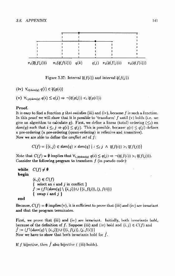
3.8. APPENDIX 141
Figure 3.37: Interval q(f( i)) and interval q(J(j))
(iv) V;Edom(q) q(i) E q(g(i))
(V) 'ifi,jEdom(q) q( i) ::;; q(j) :::} -.(q(g(j)) <; q(g( i)))
Proof. It is easy to find a fundion g that satisfies (iii) a.nd (iv ), because fis such a function. In this proof we will show that it is possible to 'transform' f until (v) holds (i.e. we give an algorithm to calculate g). First, wedefine a linear (tota.l) ordering (::;;1) on dom(q) such that i::;;/ j:::} q(i)::;; q(j). This is possible, becaust> q(i) $ q(j) defines a pre-ordering (a pre-ordering (quasi-ordering) is reflexive and transitive). Now we are able to define the conflict set of/:
C(f) = {{i,j} E dom(q) x dom(q) I i $t j 1\ q(f(i)) >; q(f(j))}
Note that C(f) = 0 implies that ViJEdom(q) q(i)::;; q(j):::} -{q(f(i)) >; q(f(j))). Consider the following program to transform f (in pseudo code):
while C(f) # 0 begin
end
(i,j) E C(f) { select an i and j in conflict } f := {ff(dom(q) \ {i,j}) u {(i, /(j)), (j, /(i)}} { swap i and j }
Because, C(f) = 0 implies (v), it is suflident to prove that (iii) and (iv) are invariant. and that the program terminates.
First, we prove that (iii) and (iv) are invariant. lnitially, both invariauts hold, because of the definition of f. Suppose (iii) and (iv) hold and (i,j) E C(J) and Î := (ft (dom( q) \ { i,j}) U {(i, f(j)), (j, /(i))} Now we have to show that both invariants hold for j.
lf f bijective, then Î also bijective { (iii) holds).

142 CHAPTER 3. ANALYSIS OF TIME IN NETS
To prove (iv), we have to show that for any k E dom(q): q(k) E q(Î(k)). (a) If k ::f. i and k ::f. j, then q(k) E q(f(k)) = q(Î(k)). (b) If k = i, then q( i) E q(f( i)) q(Î(j)). We also know that q(i) :5 q(j) and q(f(i)) >; q(f(j)), because (i,j} E C(f). The fact that q(f( i)) >; q(f(j)) implies that ( 7rt (q(f( i))) ~ 7rt (q(f(j)))) and (7r2(q(f(i))) ~ 7r2(q(f(j)))). This situation is shown in the following figure 3.37. q(k) ~ 1ft(q(f(k))) ~ 7rt(q(f(j))) = 1rt(q(Î(k))) q( k) :5 q(j) :5 7r2(q(f(j))) = 'Kt (q(Î( k))) So q(k) E 7i(Î(k)). ( c) A similar reasoning holds for k J.
Finally, we have to prove that the program terminates. Observe that there are only a finite number of bijective functions from dom(q) to dom(q) ((#dom(q))!). Using the linear ordering :5t it is possible to construct a lexicographic ordering (:51) on thesetof fundions from dom(q) to dom(q): If j,J' E dom(q) ~ dom(q), then:
f :5! J' = 3kedom(g)('v'tedom(q) 1(1) = J'(l)) 1\ q(f(k)) <; q(f'(k))) V l<tk
'v'kedom(q) J(k) = J'(k)
This ordering is a partial ordering, because is a partial ordering. It is easy to verify that :5! is reflexive and antisymmetrie (:5; is antisymmetric). The ordering is also transitive: f :5! I' and f' f" implies that I :5! f" (:5; is transitive).
If Î is the result of swapping i and j in I, then Î <1 J, because 'v'tedom(q) Î(l) = l(l) l<l*
and q(Î( i)}<; q(f( i))).
The fact that I is 'descending' with respect to :5! and that the number of possible fundions is finite tells us that the algorithm will terminate. Therefore, there exists a function g that satisfies the conditions (iii),(iv) and {v). 0
Suppose, event e consumes the tokens with a label in X Ç dom(q) from place p. Because of requirement (2.4c), we know that:
'v';ex 'v';edom(q)\X q( i) :5 q(j)
Using lemma 27, wededuce that there exists a g such that (iii), (iv) and (v) hold. This implies that:
'v';eg(X) 'v'jedom(i)\g(X) -{q(j) <; q(i})
Consequently, there exists an ë such that requirement (3.4c) holds.
The modified transition system consumes tokens having a different value in a nondeterministic manner (see requirement (3.4c) on page 84). Consider for example a

3.8. APPENDIX 143
place p containing two tokens having different values. One of these tokens has a time interval v and the other one has a time interval w. If t is an output transition of p (/t(P) 1) and t is enabled, then there are at least two allowedevents (one for each token), no matter how the time intervals v and w are related. If, for example, v (1, 3) and w = (4, 6} (i.e. all timestamps in v are smaller than any timestamp in w ), then the modilied transition system considers the event consuming the token with timestamp w an allowed event. To avoid this, we can add an extra requirement to the definition of AEon page 84. This requirement says that if all timestamps in v are smaller than any timestamp in w, then the token with time interval v is consumed before the token with time interval w (even though the values of the two tokens may differ ). More formally, we add the requirement:
place(s(i)) = place(s(j)) => timemin(s(i)) :5 timemax(s(j))) (3.4f)
For theevent ë = (1r1(e),s1 t J(dom(1r2(e))),q) E E in the proof of theorem 6, this requirement holds, because requirement (2.4c) holds for the corresponding event e. Therefore, the soundness property, that is theorem 6, also holds for the modified transition system extended with requirement (3.4f). We did not adel this requirement in the first place for the sake of simplicity.

144 CHAPTER 3. ANALYSIS OF TIME IN NETS

Chapter 4
Language and tooi
4.1 Motivation
In the previous chapters we have shown that the ITCPN model can be used to model and analyse discrete dynamic systems. However, the practical use of this Petri net model depends to a large extent on the existence of adequate computer tools. Note that this holds for most forma! models. To construct or modify ITCPNs, we need an editor. We also need one or more analysis programs basedon the techniques discussed in the previous chapter. In section 2.4 we defined an ITCPN by a seven tuple (P,V,T,I,O,F,TS). This is a definition in terms of sets, bags and mappings. To create, store, modify and analyse such an ITCPN using a computer, it is necessary to choose a convenicr1t representation comprehensible to a computer program. This reprt>sentation is called a language. In addition a language can have a number of features to facilitate the modeHing or analysis of ITCPN s.
We use the specification language ExSpect to represent ITCPNs (see Van Ilee, Somers and Voorhoeve [53], [55], [56]). The reason wc use ExSpect, is the fact that this language is basedon a timed coloured Petri net model, eaJled DES, which is closely related to the ITCPN model (see Van Hee, Somers and Voorhoeve [53]). In fact; the ITCPN model is a generalization of the DES model in the scnse that delays are described by an interval rather than a deterministic value. Therefore, ExSpect can he used for the forma! specification of a restricted class of int<'rval timed colonred Petri nets. There is a straightforward rclation between this spedfication language and the ITCPN model. In this monograph we will use the term 'specification' for df'scriptions in terms of the language ExSpect. Note that there is a strong relation hetween the terms 'specification' and 'model'. The term 'model' emphasizes the representation of one or moreaspectsof a real system. The term 'specification' is nsed to denote a concise description of the functional behaviour of a system (or softwan'). As already stated, ExSpect is based on the DES model, a timcd colonred Petri net model with deterministic delays. The reason we use th<' ITCP~ model rather
145

146 CHAPTER 4. LANGUAGE AND TOOL
than the DES model is the fact that the ITCPN model is more expressive. Another reasou for using the ITCPN model is the fact that interval timing allows for new and powerful analysis techniques. Consider, for example, the concepts refinement and uncolouring defined in chapter 3. It is not possible to define these concepts in terms of the DES model, because in the DES model delays are described by a deterministic value instead of a delay interval.
The reason we pay attention to ExSpect is twofold: (1) we can use ExSpect to specify an ITCPN and (2) we can use the analysis methods described in chapter 3 to analyse ExSpect specifications. Insection 4.2 of this chapter, we will discuss some of the features of ExSpect which facilitate the specification of complex systems.
Based on this language, a software package, also called ExSpect, bas been developed (see Somers et al. [9J). This software package is composed of a number of tools which have been developed to create, modify and analyse ExSpect specifications. These tools include: a shell, a design interface, a type checker, an interpreter, a runtime interface and an analysis tooi. The author of this monograph participated in the development of two of these tools, viz. the design interface and the analysis tooi named lAT. The design interface is a graphical editor which can be used to create and modify an ExSpect specification in a user-friendly and graphical manner. The analysis tooi can be used to analyse ITCPNs specified by an ExSpect specification. This tooi uses the analysis methods described in chapter 3.
Both the ExSpect language and the ExSpect software support the modeHing of complex systems in various application domains. However, ExSpect is a general purpose spccification language, and therefore, this language is not close to the the professional language used in a specific application doma.in. This is the reason ExSpect allows for the development of domain specific libraries. These libraries increase the productivity of the modelling process and facilitate the modelling of large and complex systems. The author of this monograph has developed two libraries: one for the modelling of queueing systems (see section 4.5 or [3]) and one for the modelling of complex logistic systems (see section 5.5, [4] or 15]).
4.2 The language
ExSpcct (EXecutable SPECification Tooi) is a language to describe discrete dynamic systems (sec [53], [55], [52], [56], [51], [57], [8), [7)). Moreover, ExSpect is a constructive specification language which means that objects (e.g. functions) are specified by a stepwise decomposition into objects that are simple and easily understood. As a result the language is exrc?tfable. Therefore, we can use the ExSpect specification for simulation (or prototyping) purposes.

4.2. THE LANGUAGE 147
Like any language ExSpect has a syntax and semantics. The syntax of a language is a grammar descrihing the systematic rules of the language. The semantics of ExSpect can be given in terms of the ITCPN model. A part of the semantics of ExSpect is given in Van Hee, Somers and Voorhoeve [51].
ExSpect specifica.tions are stored in modules. A module contains a number of definitions. Each definition in a module has a (possibly empty) interface and an implementa.tion. A user of the module only knows about the interface, and the implementation is bidden from the user. This modularization concept is also known as encapsulation. Encapsulation hides unnecessary details and if the implementation is changed, a user is not affected a.S long as the interface is not changed. Note that this is analogous tosome of the concepts found in many modern programming languages.
In ExSpect there are four kinds of definitions:
• type definitions
• function definitions
• processor definitions
• system definitions
ExSpect is a typed functional language. Type definitions are used to specify the va.lue set of each place (Vp)· Fundion definitions are used to specify operations on the value of a token (F1). ExSpect uses the term processor instead of transition. A system is a.n aggregate of tra.nsitions, places and subsystems. In the remainder of this section we discuss these four kinds of definit.ions. Fora more detailed description of ExSpect, see the ExSpect User Mariual [9].
4.2.1 Type definitions
Tokens have a va.lue. This va.lue can be very simple (e.g. a number) or very complex (e.g. a database state). Each place has a type which determines which va!ues are allowed for the tokens it contains. To create the suitable types, wc necd tyw; definitions. The type system of ExSpect consists of some primitivc types and a few type constructors. There are five primitive types: void, bool, num, real and str denoting the 'empty' type, booleans, numerals, reals and strings respectively. The type constructars are set ($), Cartesian product (><) and mapping ( -> ). From a set of types and the type constructors we can form type expressions that symbolize new ( composite) types. We can attach narnes to type expressions, thus dcfining new types. The following type definitions illustrate this:
type weight from real with [x] x >= 0.0;
type volume from real with [x] x >= 0.0;
type manufacturer from str;

148 GRAPTER 4. LANGUAGE AND TOOL
type truck from manufacturer >< (weight ><volume); type truck_id from num; type fleet_of_trucks from truckid -> truck; type cargo from weight >< volume;
Note that we can add a wi th part for restricting the type.
4.2.2 Function definitions
To specify the value of a produced token, we need function definitions. In genera}, these function definitions are composed out of simpler ones. Our set of basic functions includes all well-known set-theoretica!, logica! and numerical constants and functions. Some of these basic functions are polymorphic. Because of some 'sugaring' it is possible to write these functions in their usual symbolic infix or 'circumfix' notaLion. As an example we show two function definitions operating on the types defined above:
transportable_by_truck[ c : cargo, t : truck ] :=
(pil(c) <= pil(pi2(t))) and (pi2(c) <= pi2(pi2(t))) bool;
transportable..by_fleet [ c cargo, f : fleet_of_trucks ] :=
if f = {} then false --i.e. there are no trucks left else transportable..by_truck(c,pi2(pick(f)))
or transportable_by_fleet(c,frest(f)) fi bool;
The functions pil, pi2 (projections), piek and frest (respectively taking and deleting an element from a mapping) are examples of basic functions. To dcfine a polymorphic function, we use type variab/es. Consider for example the following function:
union[ x : $T, y $T] := if x = {}
then y else ins(pick(x),union(rest(x),y))
.fi: $T;
This funct.ion defines the union of two sets having the same type. Since T is a type variabie this function can be applied to two sets having an arbitrary type and the result of this function is of the same type. The function is recursive and uses the basic functions piek, ins and rest (respectively taking, inserting and deleting an clement from a set).

4.2. THE LANGUAGE 149
4.2.3 Processor definitions
In ExSpect we have processors and channels corresponding to transitions and places respectively. There is also a special kind of channel (place), called store, which always contains precisely one token. ExSpect uses these terms, because they seem more naturaJ for people not familiar with Petri nets.
Processor definitions are split in a header and contents part. The header part (sometimes eaJled signature) contains the processor name, its interaction structure and its parameters. The interaction structure is given by (possibly empty) lists of input channels, output channels and stores. The contents part consists of concurrent (conditional) assignments of expressions to output channels and stores. A simple example runs as follows:
proc transport..function [in leave: truck, out arrive:truck, val d:time]
:= arrive <- leave delay d;
This processor can be used to model the transport. If there is a token in the input channelleave, then the processor is enabled. If the processor transport..function remains enabled, it fires (executes) at the time given by the tim<:>stamp of the token to be consumed. If it fires, then it produces a token for output channel arri ve with a value equal to the value of the token consumed. The time between the departure and arrival of a truck is set by a value parameter (val) d. Note that delay is a keyword.
ExSpect has a number of features to make a processor definit.ion higbly generic. Besides value parameters it is possible to have function parameters (fun). It is also possible to define polymorphic functions. Consider for examplc the following processor definition:
proc p [in a:S, out b:T, val g:$5, fun t[x:S] : T, d[x:S] : real]
:= if a in g
then b <- t(a) delay d(a) fi;
This processor consumes tokens from the input channcl a. Tlwn' is onc valuc parameter (g) and there are two fundion parameters (t aml d). H tlw val11e of thc token consumed is in the set g, then the processor produces a token for output channel b.
Otherwise, the processor fires without producing a token. The va.lue and delay of the token produced depend on the value of thc tokeu consunwd. S and T are type

150 CHAPTER 4. LANGUAGE AND TOOL
•••
•••
••• • • •
• ••
Figure 4.1: A part of a distribution network modelled without preoonditions
variables, i.e. the types of the input and output channel are arbitrary. Note that the types of the value and function parameters depend on the actual type of the input and output channel. We will come back to this.
ExSpcct release 3.0 (and higher) bas been extended with preconditionsfor processors. Consider for example the following processor definition:
proc q [in a:real, out b:real I pre a > 0] := b <- ln(a) delay 5.2;
This function consumes positive valued tokens from input channel a. If this input channel only contains tokens with a value :5 0, then q can not fire. In this example we added the precondition, because the logarithm of the value of the consumed token (ln(a)) is defined for positive values only.
The concept of preconditions has been added to ExSpect to facilitate the modelling of certain situations that are difficult to specify without preconditions. These situations are found in many logistic systems. Consider for example a distribution network with one fadory and a number of warehouses. Products produced by the factory are transported to one of the warehouses. Figure 4.1 shows a part of this distribution network modelled in terros of channels (places) and processors (transitions) without preconditions. Processor (!) sends a

4.2. THE LANGUAGE 151
•••
• • •
• • • • ••
• • •
Figure 4.2: A part of a distribution network modelled wit.h preconditions
token to one of the output channels Ct, c2 , .. en. Each of the processors Wt, w2 , .. Wn
represents the acceptance of products in the corresponding ware house. For large and more complex distri bution networks it is not convenient to model the network like this, because there are a lot of channels and connections. Another drawback is the fact that, every time we decide to add or remove ware houses, we have to change the definition of processor f. Using preconditions we can avoid these problems. Figure 4.2 shows the part of the distribution network in terms of channels and processors with preconditions. Processor w1 only accèpts products whose destination is the warehouse rcpresente<l by w., etc. No te that there is only one intermediate channel ( c) and we can add extra warehouses without changing the definition of f.
In the ITCPN model there is no concept comparahle to these preconditions. However, it is possible to transform an ExSpect speeification with precouditions into an equivalent ExSpect specification without preconditiom; (e.g. replacc place c hy a subnet which tests the preconditions and sends the tokcns toa proper tra.nsition, if possible). Furthermore, it is possible to extend the ITCPN model aud the MTSRT ana.lysis method with preconditions.
4.2.4 System definitions
The main objective of the approach developed in this monograph is lo model and analyse large and complex discrete dynamic systcms, for exampl(• a large distri bution

152 GRAPTER 4. LANGUAGE AND TOOL
target environ-system ment
Figure 4.3: The transformation of an open system (the target system) into a dosed system ( the target system and its environment)
network. Clearly, a specification of such a system in termsof processors (transitions) and channels (places) tends to become too large to handle. This is the reason we added a hierarchy construct, called system, to ExSpect. This construct can be used to structure large and complex systems. The idea is analogous to the hierarchy constructs found in many graphîcal description languages, e.g. SADT (Marca and McGowan [79]), Yourdon (Yourdon [130]), Statecharts (Harel [48]) and CPN (Jensen [71]).
To clarify this construct, we start with a number of concepts adopted from systems analysis (Wetherbe [124]). System analysis is involved with the development of a framework of methods and techniques for evaluating system behavîour. Systems analysis uses an approach which conceptualizes phenomena in terms of wholes consisting of entities or subsystems with the emphasis placed on their interrelationships.
In a general sense, a system is a group of elements working in an interrelated fashion ioward a set of objectives. These elements are the smallest parts to he considered, sometimes referred to as entities or objects. Each element can be characterized by the relations with its environment. Examples of elements are humans, machines, gÓods or information processing equipment. The system boundary defines which 'part of the world' is considered and which part is out, of scope. It is possible to compose a number of systems into a new system. lt is also possible to decompose a system into a number of sub-systems. The latter process can be repeated until we reach the level of elements. A closed system is a system without any interactions with 'some' environment. An open system is a system which has a certain (external) interaction structure. Note that it is always possible to transform an open system into a closed system by explicitly modelling its environment. This is expressed in figure 4.3.
Systcms are representcd by rectangles. We use arrows to denote relations between systems. Nearly all 'real-life' systems are open. Consicier for example a humaumachine system, i.c. a person interading with a machine. From a rnadelling point of view we can consider such a system as a closed system. This is often useful for

4.2. THE LANGUAGE 1.53
Original system
Decomposed system Aggregated system
Figure 4.4: The difference between composition and aggregation
analysis. Yet, the human needs food and beverage and the machine needs electricity and maintenance. Note that the environment of a system cao only bc defined after the system boundary has been defined.
There are a lot of ways to decompose (compose) a system into (from) a numbcr of smaller subsystems without changing thesetof elemcnts (en ti tiPs). Dccomposition is a way to deal with the complexity of systems, because it. allows for the consideration of only a small part of the system at the same time. The level of abstraction rcmains the same, because thesetof entities is not changed. If a systcm X is decomposcd into a number of subsystems Xt, x~l> .. Xn, then the proper composition of X1 , X 2 , •• X,. yields the original system. If we use another set of elcmentar-y objccts (elcments) to model the same system, we speak about aggregation ( disaggregatiorz) rather than composition (decomposition). Using the terminology introduced in s<'ction 2.:3, we say that the decomposed system is equivalent (sec definition 9) to the origina.l one, but the aggregated system is merely similar (sec definition 7) to the origina.l one. An alternative term for aggregation is 'abstraction '. i.e. a.n a.ggregation st(•p
decreases the level of detail. Figure 4.4 shows the diffcrcnce between composition and aggregation. Note that the decomposed system is cqua.l to t.hc original syst.cm. However, the aggregated system is different rrom tlw original system, bccausc SO!liC
of the details are omitted.

154 CHAPTER 4. LANGUAGE AND TOOL
In genera!, a (dis )aggrega.tion or (de )composition step focusses on a specific aspect. Typkal aspects are (1) functional aspects, (2) spatial aspects and (3) timing aspects. Consider for example a decomposition of a transportation system. We ma.y decompose the system into a number of (geographical disjunct) regions, thus focussing on the spatial aspect. On the other hand, we may decompose the system into two subsystems, one for the transportation of 'fluids' and one for the transportation of 'solids'. In the latter case we focus on a functional aspect. If we disaggregate a system with respect to the timing aspect, then the dynamical behaviour of a system is modelled more precisely. For example, we model the state of a system every hour instead of every day. In this case, we change the timescale.
Several methods to develop a model ( or specification) of a system have been proposed. Top down development starts with a model at a high abstraction level, this model is refined by a number of disaggregation steps until the desired level of detail has been reached. To deal with the increasing size and complexity of the model, a disaggregation step often coincides with a decomposition step. Bottom up development starts with a model for each of the subsystems. These models are detailed descriptions of some aspect or part of the system, i.e. they have a low abstraction level. These subroodels are composed into a model of the entire system. If the overall model becomes too complex, an aggregation step is applied to abstract from some of the details. 'Pure' top down development is often impractical. 'Pure' bottorn up development would be a mess. In our opinion, a mixture of top down and bottorn up development is the most sensible way to build a model (or specification).
This concludes our introduetion to some of the main concepts of systems analysis.
We use a Petri net based approach. The elements (entities) of a system modelled in termsof a Petri net are places ( channels) and transitions (processors). The relations between these elements are represented by (graphical) connections. ExSpect has a hierarchy construct to campose and decompose specifications. This construct is called the system definilion. We define a system as an aggregate of processors, connected by channels and stores. A store is a special kind of channel: it always contains precisely one token. A system rnay also contain other(sub) systems. If asystem has no interaction with its environment, then we call it a closed system, otherwise an open system. Open systems communicate with the outside world via input and output channels and stores. Therefore, a system definition,consists of a header similar to a processor headcr and a contents part. A system can have value, function, processor and even systcm parameters. Thus, it is possible to define generic systems. In this way, a system can be customized or fine-tuned for a specific situation. The contentspart is a list of all the objects (processors, systems and local stores and channels) in the system. As an example we show the following system definition:

4.2. THE LANGVAGE
sys ts :=
channel a: truck, channel b: truck, transport_function(in a, out b, val 7 .25);
155
This is the definition of a closed system with name ts, containing two channels and one processor already defined in the previous subsedion. Note that there is a clear distinction between the definition of a processor as in:
proc transport_function[in leave:truck, out arrive:truck, val d:time]
:= arrive <- leave delay d;
and the installation in a system as in:
transport_function(in a, out b, val 7 .25)
Installing a processor means conneding the input and output channels of the processor definition to adual channels inside a system, i.e. to actually use a definition, we must instantiate the parameters with actual entities. Note that this is analogous to the separation of a fundion definition (e.g. add[x:real,y:real] := x + y : re al) and a fundion call (e.g. add (i , 2)). It is also possible to instaU systems inside an other system:
proc pi [in ii:S, i2:str, out o:S, fun d[x:S] :real] := o <- ii delay d(ii);
proc p2 [in i:S, out oi:S, o2: str ] :=
oi <- i delay 0.0, o2 <- 'nil';
sys si [in x:S, out y:S, fun d[x:S] :real] :=
channel free: str init 'nil', channel busy: S, pi(in x,free, out busy, fund), p2(in busy, out y,free);

156 CHAPTER 4. LANGUAGE AND TOOL
wai t [x: real] :=
if x < 0.0 then 0.0 else x fi:real;
sys s2 ;=
channel c1: real, channel c2: real, s1(in c1, out c2, fun wait), sl(in c1, out c2, fun wait);
System s2 is a closed system (i.e. there are no input and output channels), containing two channels and two subsystems. Note that these subsystems are both installations of the system definition s1. System s1 bas an input channel and an output channel and a fundion parameter. S is a type variable. If we instaU this system, we can conneet the input channel and the output channel .to channels of an arbitrary type (as long as they are the same). The two installations of system definition s1 in s2, are both connected to channels of type real. Note that the (required) type of the function parameter (d) depends on the type of these channels. Both installations of the system definition s1 in s2 use the function wai t with one param€'ter of type real. The contentsof system definition s1 is formed of two channels and installations of the polymorphic processor definitions p1 and p2. Figure 4.5 shows a graphical representation of system definition s2.
Note that we can replace any system composed of subsystems by a system composed of channels, stores and processors, In other words: it is possible to translate a hicrarchical system definition into a behaviourally equivalent non-hierarchical system definition. Consider for example the system definition shown in figure 4.5. If we wipe out the boundaries of the subsystems and rename the internal processors and channels, then we obtain an equivalent non-hierarchical system definition.
For practical applications of ExSpect, the system concept is of the utmost importancc. The system concept can be used to structure large specifications. At one level we want to give a simple description of the system (without ha.ving to consider all the details). At another level we want to spedfy a more detailed behaviour. This is supported by a hierarchy construct like our system concept. The system concept also reduces the length of a specifica.tion, because we can reuse a system specification (i.e. instaU a system several times). Polymorphism and several parameter types facilitate the reuse of specifications. Definitions are stored in modules. This way it is possible to hidc the implementation of a system definition from the user.
Clcarly, the system concept can be usf'd to (de)compose systems. However, in the beginning of this section we also discnssed (dis )aggregation, i.e. (dis )abstracting cert.ain aspects. Note that these proc<"sses are not supported by a particular con-

4.3. THE SOFTWARE PACKAGE 157
s
Figure 4.5: System definition s2
cept provided by the ExSpect language. For exa.mple, if we decide to disaggregate a system with respect to the timing aspect, then we have to add more detail to various parts of the specification. It is difficult to extend the language ExSpect with concepts which fa.cilitate (dis)aggregation, because changing the abstraction level requires sophisticated transformations affeding varying parts of the specificatiou. Nevertheless, these processes eau be supported by tools which facilitate complex modifications of the specification (e.g. replacing a processor by a system).
This concludes our introduetion to the language ExSpect. For more iuformation consult the ExSpect User Manual [9] or Van Hee et al. [51). Thcre are sevcral papers descrihing the application of ExSpect, see [6], [8], [7], [4] and [5].
As already stated, the reason we pay attention to Ex Speet is t.wofold: ( l) we can u se ExSpect to specify an ITCPN and (2) we can use the analysis mcthods described in chapter 3 to analyse ExSpect specifications. The rdation between au ExSpect specification and an ITCPN is straightforward except for some details which are discussed by Odijk in [94].
4.3 The software package
To support the language ExSpect, we have dcvelopcd a software package, also called Ex8pect (EXecutable SPECification Tooi), sec Somers !'!.a.I. [54], [!)]. This software

158 GRAPTER 4. LANGUAGE AND TOOL
package contains a number of computer tools. Basically the set of tools consists of a shell, a graphical editor (design interface), a type checker, an interpreter, a runtime interface and an analysis tooi.
For practical applications, the support of computer tools is necessary. There are several reasons which make computer support of crucial importance.
First of all, computer support makes it possible to obtain results which could not have been achieved manually. Most of the analysis techniques mentioned in chapter 3 are unworkable without the aid of an analysis tooi. Consider for example the MTSRT metbod which constructs reachability graphs with thousands of states: it is impracticable to do this manually.
Secondly, computer tools can reduce the number of errors. Calculations by hand are often more error-prone. Furthermore, software can he developed to check the model (specification) for (syntactical) correctness and consistency. This software detects errors like processors without input channels and typing errors. It is also possible to detect deadlocks ( traps), siphons, and the absence of certain invariants, etc.
Thirdly, computer support can be used to facilitate the maintenance of models (specifications), because tools can he used to modify a model more easily. With computer support it is often possible to obtain faster results (e.g. modifying or simulating a model).
Finally, there are some additional advantages such as an improved drawing quality of nets, which exceeds the manual capabilities, several on-line 'help' facilities, etc.
As already stated, ExSpect is a set of tools, i.e. a workbench, based on the specification language ExSpect. Figure 4.6 shows the set of tools of ExSpect. These tools are integrated in a shell, from which the different tools can he started. The design interface is a graphical mouse driven editor, which is used to construct or to modify an ExSpect specification. Such a specification is stored in a souree file (module). This souree file is checked by the type checker for type correctness. lf thc specification is correct, then the type checker generates an object file, otherwise the errors are reported to the design interface. The interpreter uses the object file to simulate the specification. This interpreter is connected to one or more runtime inlc1jaces. These interfaces enable one or more users to interact with the running simulation. It is also possible to interact with one or more external programs, for example presentation software. Recently we added the ITPN Analysis Tooi (lAT) to ExSpect. This tooi translates a specification into an ITPN, i.e. an ITCPN whose colour sets have a cardinality of 1, that is analysed using the methods described in chapter 3. The tooi also allows for more traditional kinds of analysis, such as the generation of P and T-invariants.
Thc ExSpect tools have been implemented using C and run under UNIX on SUN hardware. The tools rely heavily on the (simulated) parallelism oliered by the UNIX operating system and the graphical capabilities of a SUN workstation.

4.3. THE SOFTWARE PACKAGE
design interface
analysis tool
(lAT)
type check er
runtime interface
interpreter
extern al 1+---+t appl.
Figure 4.6: The tooiset ExSpect
4.3.1 The shell
159
The primary fundion of the shell is to integrate the other tools of ExSpect. The shell is used to a.ccess other tools, it displays the files in the current directory and it is used to reorganize parts of the file system. Although these things can be clone without the aid of the shell, the shell offers more support and is more convenient. All ExSpect tools have a mouse driven interface and the relevant information can be seen in a number of windows. In the shell you can start one of the other tools by selectinga command from a menu. It is also possible to perform operations on a file by selecting it from a window displaying the curTent directory. The shell can be customized by adding personal commands and by specifying your favourite text editor(s).
4.3.2 The design interface
Every module is stored in a separate file, often called souree file. To <:reate or modify a module, one can use a text editor such as vi or jove (like when using a programming language ). However, such an editor does not meet the requirements set by a language based on a graphical formalism. This is the reason we have devcloped a graphical editor, called the design interface. This tooi is window oricnted aJl(l allows the usc'r to observe, alter and create specifications more easily. The user is able to edit windows conta.ining graphical representaticms of systems formcd of channels, stores, processors, etc. These windows eau he use(l to create, change or delete graphical objects like channels, stores, proressor installations and

160 GRAPTER 4. LANGVAGE AND TOOL
system installations. Processor, function and type definitions are edited via easyto-use forms. At any moment we can print or save (parts of) the specification. There are a number of settings to modify some of the properties of the tool. This way you can customize the design interface. Most of these settings refer to the graphical part. For example, it is possible to change the default size and shape of the symbols used to represent channels, stores, processors, etc. It is also possible to create new graphical symbols, e.g. an image representing a truck.
Using the design interface insteadof a text editor, offers several advantages.
The most important advantage is the fact that given a graphical representation and some additional information, the tooi automatically generates a souree file. This file also contains some graphical information. At any moment it is possible to switch from the graphical editor to a text editor and vice versa. If the souree file does not contain graphical information {or this information is incomplete), then the design interface generates a default screen layout for the system definitions in this file. The user can use the design interface to adjust this layout. Othcr advantages are the possibility to do a number of checks and the fact that it is impossible to make certain errors (e.g. conneet a processor toa processor). Au additional advantage is the fact that casual and novice users do not have to know tbe precise syntax of the language. Especially for users who use a rather small subset of the language, the amount of training required is reduced.
The design interface offers the features one nowadays expects from a graphical editor. To conclude we mention two important features. First of all, the way we handle arcs differs from existing tools in this field (e.g. Design/CPN described in Jensen [71]). A conneetion (are) between a processor (or system) and a channel (or store) is considered to he a subordinate to the processor (or system) insteadof a. separate object. This has the advantage that a conneetion can be generated implicitly, i.e. the user does not have to bother a.bout drawing a. nice are between two objects. The shape of the generated are is such that it does not cross objects in the system and the lengthof the are is as 'short' as possible. Moreover, if we edit a souree file without any graphical information (e.g. a file created with a text editor), then the design interface generates a default la.yout for each system definition in the file.
Another charaderistic of the design interface is the fact that it supports bottorn up aml top down design. We can use a1ready existing definitions by simply typing the name of a definition. This way the user can build a system definition from othcr, al ready existing, system definit.ions (i.e. bottorn up). On the other hand, it is also possible to use system definitions (processor definitions) which have not been defined yct. By using a non-existing system (processor) definition we implicitly specify its interface. If we start defining this subsystem (processor), then we 'inherit' its interface (i.e. input and output channels, etc.) based on the way it was used in the suprasystem, i.e. the header of the system (processor) definition is generated automatically. This way it is possibl<> to work top down in a very convenient manner.

4.3. THE SOFTWARE PACKAGE 161
4.3.3 The type checker
A souree file, created by either a text editor or the design interface, is checked by a tooi, called the type checker. This tooi checks the type correctness and consistency of the definitions in the souree file ( also system definitions!). Si nee ExSpect is a 'strong typed' language, all type checking is clone statically. All errors which have been detected are reported in a separate window. If the souree file is correct, then the type checker produces an object file (see figure 4.6). Every souree file corresponds to a module. To hide unnecessary details, only a selected set of definitions is visible outside the module. These definitions can he used in other modules which import this module. Each module is checked separately, i.e. type checking is clone on a file-by-file basis.
4.3.4 The interpreter and the runtime interface
The object file generated by the type checker can he used to simulate the specification of a system. Simulation is one of the most powerful techniques to analyse a complex system. Simulation is easy to use and flexible in the sense that its application is not limited to a restricted class of systems. An important advantage of simulation is that it helps the experimenter to understand and to gain a fee! for the system. In a way, simulation is similar to the debugging of a program, in the sense that it can reveal errors of a ( simulation) model.
The taskof the interpreter is to simulate a specification. The interpreter is connected to one or more asynchronous user interfaces, called runtime interfaces (sec figure 4.6). Each runtime interface is implemented as a separate UNIX process. These interfaces may run on different machines (this is useful for training purposes). A runtime interface is used to interact with a simulation performed by the interpreter. For example, a runtime interface is able to inspect, add or remove tokens from a channel. All interactions take place via forms. A form has a default layout or it is user defined. This way it is possible to customize the presentation of a runniug simulation. It is also possible to conneet other external programs to the interpreter. Such a program may be used to present the results in a more convenient way or to ana.lyse some of the data generated by the simulation (e.g. spreadsheets, statistica! software). Unlike many other simulation packages, ExSpect doesnotsupport anirnation. At the moment, the only way to observe the status of a running sirnulation, is to inspeet the channels. This suffices for most simulation purposes, because we are ablc to present aggregated results in forms. However, for the debugging of a specification, animation seems to be more convenient.
4.3.5 The ITPN Analysis Tooi
Although simulation is a very powerful analysis mcilwd, it ltas a numbcr of drawbacks. For exarnple, if the specification contains a lot of IIO!l-dctPrmillism (e.g. co11-

162 CHAPTER 4. LANGUAGE AND TOOL
fticts) or has a highly stochastic behaviour, si mulation may be expensive in terms of the computer time necessary to obtain reliable results. Another drawback is the fact that it is not possible to use simulation to prove that the system has the desired set of properties. Note that these are the reasons we have developed the analysis methods described in chapter 3.
However, most of the analysis techniques mentioned in chapter 3 are unworkable without the aid of a.n ana.lysis tooi. Consider for example a typical rea.chability graph, generated by the MTSRT method, with thousands of states. lt is impracticable to construct such a graph manually. This is the reason we have developed an analysis tooi, called lAT (ITPN Analysis TooQ.
Because of (software) technical reasons, lAT can only analyse ITCPNs whose colour sets have a cardinality of one. These nets are called interval timed Petri nets (ITPNs). Fortunately, it is possible to uncolour an ITCPN, see section 3.5.1 and Odijk [94]. The corresponding uncoloured net can be analysed using the three analysis methods described in chapter 3. The analysis results generated by lAT can be interpreted for the ITCPN that corresponds to the ExSpect specification. In principle it is also possible to refine the ITCPN to obtain better results (see section 3.5.2). At the moment this has to be done manually.
place pl; place p2; place p3 init 2; place p4; place p5; trans tl in pl, p3 out p2[1.,2.]; trans t2 in p2 out p3, p4[0.,0.5]; trans t3 in p4 out p5[1.,5.]; trans t4 in p4 out p5[2.,8.];
Figure 4.7: An lAT souree file
To analyse an ExSpect specification, this specification is automatically translated into an lAT souree file. This file contains a list of all the places and transitions in thc net. Consider for example the file shown in figure 4.7. This example represents a computer system that consists of one CPU and two disks. The structure of the ITCPN for this computer system is given in figure 4.8. In the figure we see that jobs, arriving at the system (p1 ), visit the CPU unit before they visit one of the disks. The CPU unit is composed of two parallel processors (initially there are two tokens in p3 ). The service time at the CPU is between 1 and 2 seconds. Disk 1 bas an access time between 1 and 5 seconds. Disk 2 has an access time between 2 and

4.3. THE SOFTWARE PACKAGE
DISK 1
t4 DISK 2
Figure 4.8: An ITCPN for a computer system
163
8 seconds. Note that the service time at the disk is independent of the load. Aftcr a visit to one of the disks, the job leaves the system via p5 •
At the moment lAT supports four kinds of analysis:
• ATCFN
• MTSRT
• PNRT
• calculation of all minimal support place and transition invaria.nts
To calculate the minimal support invariants, we use the algorithm presented by Martinez and Silva in [84] and the modifications described in Colom and Silva [32].
To give an impression of the functionality of the tooi, we give some rcsults produced by lAT. For the net shown in tigure 4.8, there are two minimal support pla.cc invariants:
p2 + p3 = 2
pl + p2 + p4 + p5 = 0
There are no minimal support transition invariants. If we teil lAT to compute results based on the ATCFN method, then the window depicted in tigure 4.9 appears on the screen. Note that the calculaied &AT and CAT figures are lower bounds for the actual bounds of the arrival time of tlw first token, because the net contains a conflict (sec s<•ction :3.2).

164 CHAPTER 4. LANGUAGE AND TOOL
STATIC REPORT'
net id: ex __
<:omménhl:
remadu pla.ce nof--in .. tra.ns nof-out_trans EAT LAT lentative •ymEAT $ymLAT lnh
&t.u\ pi , 0 ' 0 '
0.000000 0.000000 ' ' p2 , I , LOOOOOO 2.000000 ' " , 11
' p3 , 2 , 0.000000 0.000000 ' ,
' <:onflî<:t •• ' 3
' 1.000000 ' 2.500000
' 0 ' 12 , 12 ,
end pó ' • ' 2 '
2.000000 , 7.600000 ' 0 , 13 ' 13 ,
(end of re por\)
Figure 4.9: Results calculated using the ATCFN method
DYNAMIC REPORTo
net id : ex: __ _
initia.l $late ; ex __ _
commenh: none ______ _
from : 1- to : 3-
number numbu of
of a.vaila.bl~
pi ace &okens toleens 1 2 3 min min max EAT LAT EAT LAT EAT LAT
pi 0 0.000000 ·o.oooooo 1.000000 1.000000 1.000000 1.000000
p2 0 0 1.000000 2.000000 2.000000 JNF INF INF
p3 0 0.000000 0.000000 0.000000 0.000000 0.000000 0.000000
•• 0 1.000000 2 . .')00000 2.000000 INF 2.000000 INF
pS 2.000000 10.~00000 3.000000 11.500000 3.000000 12.500000
{end of report)
Figure 4.10: Results calculated using the MTSRT method
Figme 4.10 shows a window which contains some results calculated using the MTSRT method. This window displays information about the arrival times and boundedness given some initia! state. There are several ways to calculate the reachability graph. It is possible to select a suitable 'strategy' for this purpose (see Van den Heuve1 [61]). Depending on the net and the chosen strategy, lAT is able to generate up to 100.000 statesin less than a minute (on a SUN SP ARC SLC). Experience tells us that the upper limit of the performance of lAT is more Iikely to be set by the

4.4. ENGINEERING THE MODELLINO PROCESS 165
available memory than by the processor speed. An extensive description of lAT is given in Van den Heuvel [61]. Examples of the application of lAT are given in Odijk [94] and in [2].
4.4 Engineering the modeHing process
Both the ExSpect language and the ExSpect software, support the modeHing and specification of large and complex systems. Although this is true, ExSpect is not a panacea. For example, the powerful constructs provided by ExSpect can be abused to produce unreadable specifications; As long as the system to be modelled is smal! there are no problems. However, thc modeHing process becomes probiernatie when the system is large or complex. The specification of such a system is often too complex and not transparent enough to comprehend. To deal with this problem, we propose the development of domain specific libmries of reusable components. Examples of reusable components are predefined gencric system definitions, mathematica! function definitions and typical type definitions. The use of these reusable components insteadof ad hoc definitions, results in a highlevel specifica.tion of the system, i.e. the size and complexity of the specification is reduced. There are some other advantages. First of all, reusability is a way to increase the productivity of the modelling process, i.e. it is possible to specify thc system in less time. Secondly, domain specific libraries of reusable componentscan be used to capture knowledge. When making a reusable component, some domain knowledge is acquired by the modeller. In a way, this knowledge is stored in the components. Reusing these components facilitates the ditfusion of this knowledge.
A domain specific library is composed of a number of modules eontaining all sorts of definitions. These predefined definitions are called componenls or building blocks. The term 'building block' expresses the fact that we are able to combine system definitions graphically. This is also the reason we sometimes use the term tooibox instead of domain specific library.
Basically, there are two wa.ys to reuse these components. The most easy way to reuse predefined components, is to use thcrn without nny modifications. Consider for example the use of a library containing standard mathematica! functions. Another example is the use of predefined subsystems likc a 'generator', 'duplicator' and 'absorber'. If present, parameterscan be used to customize the component. Suitable parameters make a component gcncric, i.e. it eau be applied in ma.ny situations. To use componentsin this manner, it suffices to know the header of the definition (i.e. it is not necessary to know the internal structure). Another wa.y to reuse specifications, is to modify pa.rts of alrea.dy existing components. This kind of reuse poses a number of problems. To modify existing definitions, the user needs information about the exact (interna.l) behaviour of snch a component. Without a full understanding of the opera.tion of the component, this kiml of

166 CHAPTER 4. LANGUAGE AND TOOL
method
library
8 Figure 4.11: The result of domain analysis
reuse is dangerous and likely to cause errors. Therefore, we dissua.de this kind of reuse by novice users.
Our ma.in interest in domain specHic libraries sterns from the realization tha.t reuse supports and speeds up the modelling process. We aim at a '80/20'-situation, where 80 percent of the components needed are already availa.ble in standard libraries and take up only 20 percent of your time. But the 20 percent you have to create yourself take up 80 percent of your time. This 80 percent includes the time used to modify existing components.
Clearly, this is an ambitious goal. We think this situation is feasible in various domains (supported by a domain specifîc library), beca.use ExSpect has a number of constructs that allow for the development of highly generic components, which are easy to use. To motivate this statement, we list some of the constructs which have been described in section 4.2. ExSpect supports composition and decomposition by a hierarchy construct, called system. The system concept offers the possibility to use gencric building blocks that can be combined graphica.lly. The module concept can he used to hide unnecessary details (encapsulation). Polymorphism by type variables is very powerful, since it allows for the development of components which are (partially) independent of the actual type of an instantiated parameter. For example, it is possible to define functions that can be applied to any kind of set (e.g. the definition of union). Procèssor and system definitions can have several parameters (a system definition can even have processor and system parameters). This way it is possible to develop highly gencric components, which can be customized for a specific application.
To develop powerful toolboxes, we have to do some domain analysis. In this monograph we consider domain analysis as an activity prior to the actual modeHing of a

4.5. A LIBRARY: QNM 167
partienlar system and whose output supports the modelling of any system in this domain. Domain analysis tries to generalize situations rather than focus on a particular system. The result of domain analysis is a library which transcends a specific application. In a way, ExSpect and such a library make up a domain specific language. This way it is possible to create a language which is close to the user's professional language. Nevertheless, for some application domains this is not sufficient, because the complexity of the problem requires a systematic approach. To support the use of a library in such an application domain, we have to supply a rnethod. This is expressed in figure 4.11. Such a metbod is a collection of rules a.nd guidelines to support the modeHing process in a. systema.tic ma.nner.
A libra.ry is formed of a. number of modules. Some of these modules are a.lso part of other libraries. At the moment there are five standa.rd modules:
basic elementary mathematica} and logica! functions, like set insertion, etc.
utils more mathematica} and logica! functions
stat statistkal functions, e.g. a function to generate random numbers
adt operations on abstract data types Iike arrays, lists and bags
qn components that can be used to model queueing networks
We have used ExSpect to model all sorts of systems: queueing systems, information systems, protocols, production systems, etc. However, our main interest is in the field of logistics. In chapter 5 we descrîbe a library that has been developed for this domain. In this chapter we also propose a method to facilitate the modeHing of logistic systems. To illustrate the use of a domain specific library, we sketch the QNM library, which is composed of only one module: the qn module (see Van der Aalst [3]). Since the componentsin this module are self-explanatory for users familiar with queueing networks, we restrain ourselves from presenting a method.
4.5 A library: QNM
In the last twenty years, queueing networks have become popular in the field of performance analysis of computer systems, communication nctworks and production systems. A common feature of all these systems is the fact that there is à limited resource which must be shared among a number of competing ettstomers that requirc service. Examples of typical shared resources are CPUs, memory, I/0 device:-;, transport aids and machines. Since these resources are lirnited, customers may have to wait. These waiting customers form a queue in front of the shared resource. Th is is the reason these systems are called queueing syslcmt<. In other words: a queueing

168 GRAPTER 4. LANGVAGE AND TOOL
system is a network of queues and servers containing a number of customers ( clients) circulating in the network.
There exist two approaches for the analysis of queueing networks. The most flexible and easy-to-use method is simulation. Simulation can he applied in many situations and, by nature, it provides the opportunity to model and analyse systems which are mathematically intractable. Simulation is not the only way to analyse queueing systems; 'pure' queueing systems also allow for analytica! methods. In fact the ma.in reasou for which queueing networks have become so popular is due to the product form solution property that holds for a fairly large class of queueing networks (see Baskett et al. [13)). Nevertheless, several practically important features, like synchronization, blocking and the splitting of customers can usually not he modelled in such a way that the model still has the product form solution (see Ajmone Marsan [83]). For non-product-form queueing networks there are approximative methods of analysis available, but these are not generally applicable and require an expert consultant. Therefore, for a more detailed analysis of queueing systems simulation is practically unavoidable.
We propose a hybrid approach. This approach is based on the Queueing Network Module (QNM), a library containing one module ( qn). This module contains a number of building hlocks, like a generator, a server, a queue, etc. These building blocks allow for the modeHing of a fa.irly large class of queueing networks, in a graphical manner. The design interface automatically generates a simulation model allowing for all sorts of measurements. Under eertaio conditions, it is possible to translate such a model into a BCMP network (see Baskett et al. [13]). Such a network can he analysed using standard analytica! techniques. If these conditions are violated, then the simulation results are still useful; they can be used to obtain parameters for an approximated BCMP networkor to compare them with the results of an analytica! technique. See [3] for more information about the relation between QNM and BCMP networks.
One ca.n think of QNM as an interface on top of ExSpect. This interface prevents the user familiar with queueing networks from having to learn a new forma.lism. It fully utilizes the features of the la.nguage ExSpect such as polymorphism, value and fundion parameters, hierarchical modelling and encapsulation.
The qn module contains definitions of the following building hlocks:
generator The generator component takes care of the generation of new cus·tomers.
server The server component satisfies the needs or requirements of arriving customers. Most servers have a limited capacity, i.e. the number of customers being served at the sametime is restricted.
queue When a server is too busy to serve incoming customers, these customers

4.5. A LIBRARY: QNM 169
have to wait fortheir turn. U pon completion of a service, the queue selects the customer that must be serviced next, according to some queueing discipline. The queue component takes care of the buffering and selection of waiting customers.
assign Sometimes we want to model one queue in front of a number of (possibly non-identical) servers. To do this we have to use the assign building block.
selector The selector component takes care of the routing of customers.
assembie The assembie building block is used to synchronize two queues.
term Customers arriving at the term component leave the queueing network.
Each component has its own graphical symbol. Figure 4.12 shows the symbols used by the design interface to picture a queueing network. A complete description of these components is given in [3]. In this section we focus on two components: the server and queue system.
Server
The customers in the network travel from server to server until they leave the system. At each server they offer a certain amount of work (the workload) and they wait until the server has completed the service. One can think of a server as a service point or a workstation. A server is always connected toa queue (sometirnes indirectly via an assemble and/or an assign system). If the server is free and therc are customers waiting to be processed by this server, then the server system starts serving one of the customers. The service time is given by a probability distri bution which may depend upon the value of the customer. One can also use the server system to model a number of identical parallel servers or an infinite server (i.e. a station with an infinite number of servers). The header of the server system looks as follows:
sys server[ in i:S, out o:T, sig:signal, val name:str,
seed:real, nofservers:num,
fun servicetime[x:S,r:real] :real, transform[x:S]:T
] j
The server systern is polymorphic, because S a.nd T are type va.ria.bles. Input channel i and output channel o are used to model the a.rriva.l a.nd departure of customers. There is one other output cha.nnel, called sig, tha.t is used to inforrn thc preceding queue system (or assign or assemble systcm) that the server is ready to

170 CHAPTER 4. LANGUAGE AND TOOL
B--
assemble
Figure 4.12: The symbols used by the design interface
process another customer. The output channel sig is of type signal, a predefined type with only one element, also called signal. The value parameter name is used to specify the name of the server and seed is used to set the random generator. The number of parallel servers inside the server system can he specified via nofservers, this value parameter is set to INF to model an infinite server. The service time of a customer is given by the function parameter servicetime and may depend upon the value of the customer (x) and a random number (r). Note that the service time may be fixed, calculated by an expression or random with a particular probability distrihution. Since a service can change the attributes of a customer, a function parameter, called transform, is supplied. The input of this function is the value of the arriving customer (x), the output is the value of the processed customer. Note that the resulting type of this function and the type of the output channel o have to 'match'.

4.5. A LIBRARY: QNM 171
Queue
A queue is used to store the customers waiting to be served. The order in which the customers leave the queue is defined by the service discipline, for example FIFO (first-in-first-out), LIFO (last-in-first-out) or SIRO (select-in-random-order). A queue system is always foliowed by a server, assemble or assign system.
sys queue[ in i:T, sig:signal, out o:T, val name: str,
seed:real, fun discipline[n:num,x:T,r:real] :real
] ;
Input channel i and output channel o are used to model the arrival and departure of customers in a queue. Note that T is a type variable. The input channel i reccives customers from generator, serverand selector systems. There is also an input channel called sig used by a server, assemble or assign system tosend a message to tel! the queue that it is ready to accept new customers. If the queue contains customers and there is a token intheinput channel sig, then a customer is selectcd and sent to the server, assemble or assign system. The name of the queue is specified by a value parameter called name. The function parameter discipline is used to specify the service discipline, which may depend upon the arrivalnumber (n), the value of the customer (x) and a random number (r). The function returns a real value for every queued customer, i.e. discipline assigns a weight to every waiting customer. The queue always selects the customer with the highest weight to leave the queue. Note that this way it is possible to specify various service disciplines, e.g. FIFO, LIFO, SIRO, priority scheduling, etc.
To illustrate the use of the QNM library, we present a small example. In this example the QNM building blocks are used to model a jobshop producing rolled products. The jobshop receives iron bars from a blast-furna.ce plant. These ba.rs are transformeel into steel plates using rolling mills to flatten the iron ba.rs, and cutting machines. This transformation process takes a number of steps. The sequencc of operations transforming an iron bar into a finishcd product is called a job. Since the QNM building blocks are polymorphic, we have to specify a. type descrihing the attributes of a customer. If the user does not want to bother about this, (s)he ca.n use a predefined type, called elient (see [3]). In most cases this type is convenient. However, in this example wedefine our ow.n type (job):
type product from str; type operation from str; type date from real; type duration from real;
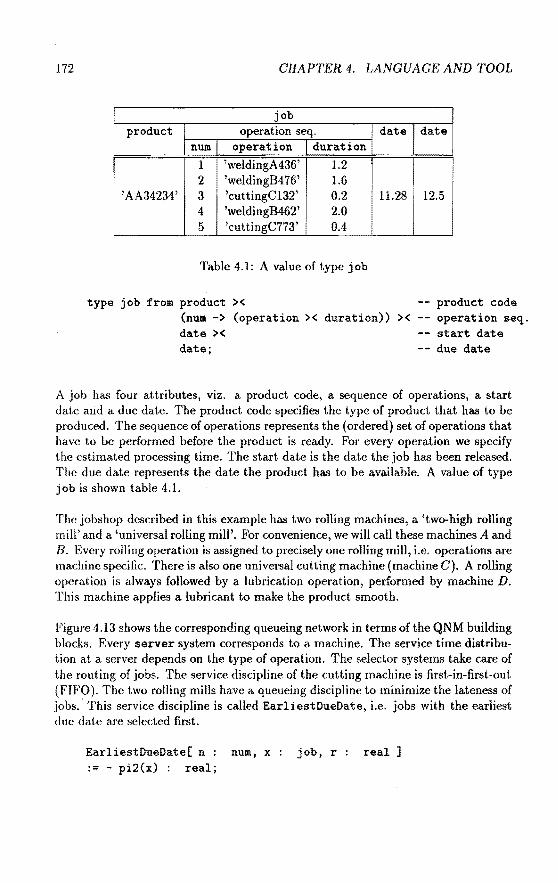
172 CHAPTER 4. LANGUAGE AND TOOL
job product operation seq. date date
num operation duration
I 1 'weldingA436' 1.2 2 'weldingB4 76' 1.6
'AA34234' 3 'cuttingC132' 0.2 11.28 12.5 4 'weldingB462' 2.0
i 5 'cuttingC773' 0.4
Table 4.1: A value of type job
type job from product >< -- product code operation seq. start date due date
(num -> (operation >< duration)) >< date >< date;
A job has four attributes, viz. a product code, a sequence of operations, a start date and a due date. The product code specifies the type of product that bas to he produced. The sequence of operations represents the (ordered) set of operations that have to be performed before the product is ready. For every operation we spedfy the estimated processing time. The start date is the date the job has been released. The due date represents the date the product has to he available. A value of type job is shown table 4.1.
The jobshop described in this example has two rolling machines, a 'two-high rolling mill' and a 'universa! rolling mil!'. For convenience, we will call these machines A and B. Every rolling operation is assigned to precisely one rolling mill, i.e. operations are machine specific. There is also one univeraal cutting machine (machine C). A rolling operation is always foliowed by a lubrication operation, performed by machine D. This machine applies a lubrica.nt to make the product smooth.
Figure 4.13 shows the corresponding queueing network in termsof the QNM building blocks. Every server system corresponds to a machine. The service time distribution at a server depends on the type of operation. The selector systems take care of the routing of jobs. The service discipline of the cutting machine is first-in-first-out (FIFO). The two rolling mills have a queueing discipline to rninimize the latenessof jobs.· This service discipline is called EarliestDueDate, i.e. jobs with the earliest duc date are selected first.
EarliestDueDate[ n num, x job, r real ] := - pi2(x) : real;

4.5. A LIBRARY: QNM 173
Figure 4.13: A jobshop modelled with QNM-ExSpect
Note that jobs are selected in deseending order of their due date (pi2(x) ). Machine D uses priority scheduling, jobs are discriminated by the machine they come from. Products coming from machine A have priority over products coming from machine B, because they tend to he voluminous. Products coming from thc samc machine are servicedinorder of their arriva.l (FIFO). The graphical representation (figure 4.13) of the jobshop was crcated with de design interface of ExSpect. The structure of the model is defincd in a completely graphical way. This only takes a few minutes. To fecd thc model with parameters (distrihutions, queueing disciplines, etc.) also takes a few minutes. Then thc model is ready to he simulated. The runtime interface allows the user to observe a running simulation. During the simulation the runtime interface reports several mcasurcments (waiting times, queue lengths, etc.). It is also possible to export data toa. statistica! package or presentation software.
For an importantdassof queueing systems we have creatcd a '100/100'-situatiou, i.e. all components (100 percent) flf.'f'd<>d are alrcady available in Lhe qn module, and therefore, the usage of these componcnts takes up 100 p{'rcent of your time. This class includes queueing systems suhject to phcnonwna such as synchronizat.ion,

174 CHAPTER 4. LANGVAGE AND TOOL
blocking and the splitting of customers. Features which cannot he modelled with the building blocks described in this section, are 'preemption' (i.e. a service is interrupted) and service times depending on the queue length. The module qn fully exploits the graphical capabilities of ExSpect. Our approach combines the advantages of a simu/ation package (focused on a limited field of applications) and a simu/ation language (flexible, but not easy to use). Another advantage is the possibility to create your own building blocks using a hierarchy construct. This is an important improverneut compared to other graphical simulation tools. A much more detailed description of QNM can be found in (3J.

Chapter 5
Modelling logistic systems
5.1 Introduetion
Modern organizations are required to offer a wide variety of products, in less time than previously and at competitive prices. To meet. these requirements such an organization has to devote a lot of energy to a continuous improverneut of its logistic performance. To improve the overall logistic performance, it is necessary to investigate how the logistic components contribute to the logistic performance of the organization as a whole. Clearly, this is a complicated task. In this chapter we focus on means to support this task. In particular, we investigate which role the theory, tools and methods described in the previous chapters can play in the area.
Our contri bution to the solution of probieros related to the modeHing and analysis of complex logistic systems is threefold:
1. An answer to the question: 'Why Petri nets?'. To motivate the fact that we use a Petri net based approach, we wil! show that, in genera], alogistic process can be represented by a Petri net in a very natura! manner (e.g. goods and capacity resources are represented by tokens, buffers, storage space and media are represented by places, and operations are represented by transitions). We also show how to model typ i cal logistic processes in terros of iimed coloured Petri nets. Other reasons to use Petri nets are the graphical nature, the firm mathematica! foundation, the analysis methods and the availability of computer support. Furthermore, we wiJl compare our approach with more conventional approaches used to model and/or analyse logistic systems.
2. Another contribution of this research lies in the construction of a 'systems view' of logistics. Based on a taxonomy of the flows in a logistic system, we describe a systematic approach to the modelling of logistic systems. This approach is used to structure the field of logistics, e.g. we identify typical control structures.
3. Finally, we have developed an ExSpe~t library of logistic components, based on our systems view of logistics. These components are generally applicable
175

176 GRAPTER 5. MODELLINO LOGISTIC SYSTEMS
and therefore they can be used in a variety of logistic applications. In a way, ExSpect and this library make up a domaio specific language, close to the user's professio!lallanguage.
In the previous chapters we discussed concepts, techniques and tools to model and analyse discrete dynamic systems. Therefore, we restriet ourselves to logistic systems which are discrete, i.e. the flows of goods, materials, capacity resources, information and control are composed of identifiable entities.
The approach presented in this chapter is characterized by a number of salient features. First of all, our approach provides an integrated perspective for various logistic flows, i.e. flows of goods, capacity resources, information and control are modelled using the same concepts. Moreover, we focus on the main logistic functions (e.g. transport, demand, supply, production and stock holding) in a unifying way. This is possible, because we restriet ourselves to the functional behaviour of the system and we ignore aspects like administration, safety, personnel, etc. If convenient, we also abstract from the physical reality, i.e. we are not interested in the actuallayout of alogistic system, mechanica! aspects, communication protocols, etc. Secondly, our approach is characterized by the fact that during the modelling process the user is not shackled by the techniques that are going to be used to analyse the model. Many techniques used in operations research, enforce implicit modelling decisions, i.e. the problem statement is simplified to allow for analytica! solutions. Furthermore, the analysis techniques to be used depend on the questions that have to be answered, i.e. sometimes different types of analytica! models (solvers) are used to answer different questions within the same situation. Therefore, in [122] and [123], Wessels advocates the use of a 'solver-independent' medium for the modelling of the system, e.g. Petri nets. Modelling in terms of timed coloured Petri nets is characterized by a high degree of freedom. Moreover, timed coloured Petri nets allow for various kinds of analysis, see chapter 3. Therefore, we can use one model to analyse the system using different kinds of analysis.
To clarify the problems we are dealing with, we start with a short introduetion to logistics. The rest of this chapter deals with our approach, based on timed coloured Petri nets, concepts from systems analysis and knowledge from logistics as an application domain.
5.2 Logistics
This section provides a short introduetion to the nature and purpose of logistics, intended for readers not familiar with logistics. A logistic process consists of the flow of goods and services and the monitoring and control of these flows. Typical activities inclnde: transportation, inventory management, order processing, warehousing, distribution and production. Logistics

5.2. LOGISTICS 177
management is concerned with the development of functions to support these activities. A simplified definition of logistics is: "The process of having the right quantity of the right item in the right place at the right time" (Hutchinson [68]).
The period of the early 1950s through the 1960s represents the takeoff period for logistic theory and practice. Prior to this time, the field was in a state of dormancy (except for military logistics). Business fragmented their management of the key logistic activities, i.e. there was no integration of the logistic activities. Some reasous for the increased interest in logistics are: a squeeze on profits during this period because of the economie elimate and the increased variety in the goods demanded by the consumers. The recession in the early 1970s stimulated a change in priorities from the production of products to the service of demand. There was a shift from a 'sellers market' toa 'buyers market', which forced companies to offer a diversity of products in a swiftly evolving market. Companies were forced to react swiftly upon changes in the market and to deliver an increasing variety of high-quality products within tight terms of delivery. To meet these requirements, companies had to improve the control of their logistic activities. During these years there was a trend towards the integration of the logistic activities to improve efficiency and to reduce costs. This trend still exists and is stimulated by progress in computer technology allowing for more complex calculations.
Logistics management often has to deal with conflicting interests within the same enterprise. Consider, for example, the stock levels inside a company. The marketing and production departments like to have high stock levels to be able to sell from stock and to produce in large batches. The financial department, ho wever, \ikes to have minimal inventories to reduce interest costs and the costs of loss of inventory due to deterioration or getting out of date. To avoid sub-optima! solutions the total cost concept was developed. The total cost concept reflects the recognition that conflicting cost patterns should be examined collectively. For cxample, when choosing the mode of transportation, the total cost concept would cncourage us to consider the impact of the decision on the firms inventory.
The two main objectives of logistics management are a reduction of the overall logistic costs · and an improvement of the service provided to the customers of the firm. These objectives have to be balanced at optimum ( depending on the branch of industry and the firm's competitive situation). Therefore, we elivide the logistic performance into the internal logistic performance and the external logistic pcl·formance. The external logistic performance is often called the cuslomer se1·vicc capability. Elements of customer service are: availahility, avcrage delivery time, deviation of delivery time, flexibility and quality. The interna.l logistic performance refers to the efficiency of a logistic system to maintain a certain customer service level. Elements of the internal logistic performance are: stock levels, number of transports, number of set ups, required supplier pf'rformance, avcrage lead time aud handling costs. Note that the internal logistic performance is directly related to the

178
supply channel
supply logistics
GRAPTER 5. MODELLING LOGISTIC SYSTEMS
logistics management
distrihution channel
production logistics
distri bution logistics
Figure 5.1: A schematic view of a logistic chain
total cost of the logistic process.
The logistic performance is often measured using (key) performance indicators. A performance indicator quantifies a specific aspect of the logistic performance. Examples of performance indicators are the percentage of deliveries exceeding their duc date, the percentage of backorders and the average stock levels.
We often call the channel with goods flows and information from supplier to consumcr the logistic chain. The flow of matcrials and products in a logistic chain proceeds through a series of consecutive locations as it moves from origin to the final destination. This flow of goods has to he controlled, logistics management (or business logistics) takes care of the overall coordination of the logistic chain. For discussion, logistic operations are divided into three categories: (1) supply logistics, (2) production logistics and (3) distribution logistics.
The task of supply logistics is to satisfy the needs of an operating system, sucb as a manufacturing production line or a warehouse, i.e. it controls the inbound flow of materials. Supply logistics manages the part of the logistic chain called supply channel. Typkal activities in tbe supply channel are: acquisition of inaterials, matcrials handling, transportation of supplies to the plant and the maintenance of thc invcntories at the plant.
Production logistics controls the flow of semifinished components, i.e. the flow of goods between the stages of manufacturing. The objective of production logistics is to control the goods flow such that the products are produced at the right time in the right quantity given the operational ( capacity) constraints of the production j)l'OC<'SS.
5.2. LOGISTICS 179
Distribution logistics is concerned with the movement of products to the customers. It deals with the transport, storage and service of goods that need no further processing within the firm. These finished goods are stored in a central warehouse, a field warehouse or shipped directly to the customer. The main objective of distribution logistics is to provide the availability of the product to the n1stomers as and when they desire it and at minimal costs. The part of the channel controlled by distribution logistics is called the dist1·ibution channel. Typical decisions are: where to locate inventories (and how large) and the mode of transportation.
Figure 5.1 shows a logistic chain. Several authors (e.g. Bowersox [24]) use the terms materials management and physical distribution instead of supply logistics and distribution logistics respectively. However, these terms are also used to describe specific aspects of logistics management. Note that the total logistic chain (from raw material to the consumption of endproducts) often stretches out over a number of different enterprises. If we consider a number of companies at the same time, we talk about interorganizafional logistics. The role of a company depends upon the scope of the logistic chain we want to consider. From a manufacturers point of view a retailer is a consumer. From a retailers point of view a customer is a consumer and the manufacturer is a supplier.
The management of thesetof logistic processes can be decomposed into a hierarchy. Figure 5.2 shows a typical control hierarchy for the field of logistics. Most authors distinguish three categoriesof decisions: (1) strategical decisions, (2) tactical decisions and (3) operational decisions (see Anthony [11]). Decision making at a strategical level is the process of establishing corporate goals and organizational objectives. Expanding marketing activities into a new geographical territory, introducing new products and building plants are typical strategical decisions. An interesting strategical question in the field of physical distribution is: 'Do weneed regional warehouses?'. The time span of such a decision is long (several years) and the impact is high. Tactical decisions are made to select the methods to achieve organizational objectives. At this level we are concerncel with aggregate production rates and aggregate inventory levels. Examples of tactical decisions are the ciccision to buy an extra machine and the construction of the Ma.'lter Production Scheeluie (MPS). Operational decisions are made to control the manufacturing and logistic processes from day to day. These decisions are at a detailed level and tbc impact on the entire logistic chain is low. However, the frequency of these decisious is very high. Examples are detailed scheduling, dispatching and routing. Note that each level has a different function and operates on a different time scalc. Time scales may range from years and months to minntes a.nd seconds on the shop floor. Even within the same level, these time scales may vary consi<lerably.
In this chapter we propose an approach to the modelling and a.nalysis of logistic systems, based on the concepts introduced in the previous chapters. Thc total cost concept and the importance of a good customer service force us to considcr the

180 GRAPTER 5. MODELLll'>IG LOGISTIC SYSTEMS
I - marketing planning
- product planning
facilities location
1 !
- production planning
inventory planning
- transport planning
1 - production scheduling
- reai-time scheduling
- order picking .
routing
Figure 5.2: A control hierarchy
strategical decisions
tact ie al decisions
operational decisions
entire logistic chain. The observation that there are at least three levels of control (stratcgical, tactical and operational) shows the need for an integrated framework, i.c. a framework which is able to deal with logistic problems at various abstraction levels. We propose a framework based on a timed colonred Petri net model. This framework is made up of the software package ExSpect, a logistic library a.nd a method which provides guidelines for modeHing with this library.
5.3 Why Petrinets?
To realize the objectives, set out in the previous section, we use a framework based on a timed coloured Petri net model. In this section we wil! motivate our choice to use a Petri net based approach. We wil! show that Petri nets allow for a natura} represcntation of discrete logistic processes. Note that there are several other reasous to use Petri nets, e.g. the graphical nature, the firm mathematica} foundation, the allalysis methods and the availability of computer support. We also discuss some of

5.3. WHY PETRINETS ? l8l
the features of ExSpect in the light of logistics.
Logistic systems take care of the flow and storage of ra.w materials, in-process inventory and finished goods. Since ston•d goods can he seen as f!owing goods with speed zero, the main objective of logistics is to control the flow of goods. We suppose that these goods are discrete, i.e. it is possible to identify single products. Examples of non-discrete logistic systems are the production and transportation via pipelines of liquids and gasses. In most cases, however, it is possible to model a continuous process in a discrete way.
Besides the flow of goods, alogistic system camprises a diversity of information flows (e.g. control flow, orders, requests) and means (e.g. machines, tools, rnanpower). Hence, we require a frarnework which allows for the modeHing of these flows in a unifying way.
A logistic systern is distributed over a nurnber of sites. For example: demand, supply, production and storage often occur at different geographical locations. This implies that va.rious processes happen at the same time, i.e. in pmYtllel. To model these processes it is convenient to have a graphical forma.lism which expresses the distributed aspect of a. logistic system.
Since alogistic system comprises processes happening in parallel, it is necessary to he able to model synchronization. Synchronization is also induced by assembly (an operation has to wait for specific goods) and control (an operation has to wait for the proper command), etc.
In the remainder of this section we will show that Petri nets, extended with time and colour, come up to the requirements just stateeL
First of all, Petri nets are wel! suited to model many dijJe1·enl logistic flows in a unifying way. Modelling the flow of goods, means, information, etc., by tokens secms to be very natural. A place either represents a medium through which sarnething is sentorsome storage space (i.e. a buffer). The fact t.ha1. flows are represented graphically is a very important quality, since it makes the overall structure cornprehensihle and supports the communication between people having different backgrounds.
We focus on discrete processes, i.e. products, pieces of information, etc. are idcntifiable. Having discrete ftows of products implies tlw existcncc of operations on these products. The definition of the set of logist.ic operations depends on thc scope and the level of detail we want to consider. For this purpose, clcmcntary steps are aggregated into operations. Considcr, for examplc, an assembly proccss. Elcmeutary steps in such a process are: 'fetch tools', 'set-up', 'load part!', 'loacl part2', 'move robot arm', etc. In most cases we want to model sudt a sc•qtwncc> of steps as a single operation. Another exa.rnple is the production in 'hatch<'s', whcre all elementary steps are per piece. In this case we of!Pn consider op<'ratious ddined p<'r

182 GRAPTER 5. MODELLINO LOGISTIC SYSTEMS
batch instead of per piece. These examples learn that the definition of an operation depends on the desired level of detail. In a logistic process there are all sorts of operations. When modelling, we often identify the following five attributes of a logistic operation:
1. required goods (materials, goods)
2. required capacity resources
3. processing time of an operation (without waiting times)
4. usage pattem of the capacity resources during the operation
5. produced goods
Generally, these attributes capture the essence of a logistic operation. The firing mechanism of a Petri net allows for the modelZing of an operation in a very elegant and transparent way. We can think of an operation as a set of events and activities. Events are represented by transitions. An activity is associated with the firing of a transition or with the presence of a token in a place. An event occurs if all input conditions are met, i.e. each of the input places of a transition contains enough tokens. In this section, we will show that timed coloured Petri nets are wèll suited to model the five attributes of a logistic operation.
Petri nets also allow for the rnadelling of true parallelism and synchronization. By true parallelism we mean that parallelism is clearly differentiated from nondeterminism, as opposed to the intericaving of events. To get an impression of the modelling capabilities of Petri nets we show some elementary network structures.
Causality
o-+--o There is a causality relation between the input places and the output places of a transition. No event may be generated 'spontaneously', i.e. without an input event that directly or indirectly caused it.
Divergence There are two kinds of divergence:
A token produced by a transition is assigned to some other transition in a

5.3. WHY PETRINETS ? 183
non-deterministic manner. Only one of the output transitions consumes the produced token. These transitions ( events) are said to be in· conflict with each other. This way it is possible to specify a non-deterministic routing.
The consumption of a token by some transition results in a number of tokens. This may be interpreted as breaking up an object into a number of (smaller) objects. One can think of a disassembly of a product or an operation having side-effects. An alternative interpretation for this net structure is: one condition implies a number of other conditions. Note that if we use a coloured Petri net model, the number of tokens produced for each output place may depend upon the value(s) of the token(s) consumed. For example, this network structure also matches a 'switch' which sends a token in one out of three possible directions.
Convergenc.e There are also two kinds of convergence:
Several events cause the same result, i.e. there are scveral ways to meet a condition. This way it is possible to model a converging flow of goods. For example, a number of production units producing products that are storcd in the same warehouse.
This is a synchronization primitive comparable to the join operation in a computer system. An event occurs if a number of conditions hokl. Compare this with the assembly of a number of components into a product.
circuit A circuit in a net is a sequence of placcs aml transitions conneeteel to eaeh other sueh that the sequencf' starts and ends in t.he sauw place. Snelt a

184 CHAPTER 5. MODELLING LOGISTIC SYSTEMS
construct is often used to model capacity constraints, reusable matcrials or a cyclic demand. An example of a capacity constraint is a shared resource, for instanee an operator working on a number of machines.
Circuits play an important role in the rnadelling of logistic systems.
,----------------------~
(ree
ingoods outgoods
Figure 5.3: A machine having a finite capacity
First of all, they are used to model a finite capacity. Consicier for example the net shown in figure 5.3. This net represents a machine (or a set of machines) capable of handling n jobs at the same time ( n is the number of tokens initially in place frec). Delay d1 represents the time a job uses a capacitated resource, delay d2 is thc rcmaining processing time.
push pop
.--1----------1 B '""'
ingoods outgoods
Figure 5.4: A bounded buffer
Another example of a resource with a finite ca.pacity is a buffer of size n, i.e. a bounded buffer (see figure 5.4). The tokens in place occupied represent the stored products. The buffer 'releases' a product if there is a token in pop and the buffer contains at least one product. To store a product there has to be a token in place ingoods and in place push, and there has to be enough space in the buffer. We often omil. the place push to model the propet-ty that goods are stared as soon as possible. Circuits are also used to model shared resources. Many operations use one or more 8harcd resources. Examples of shared resources are: an operator working on a

5.3. WHY PETRINETS ? 185
Figure 5.5: A competitive shared resource
Figure 5.6: A cyclic shared resource
number of machines, loading/unloading facilities and the central computer systcm. In fact a machine itself can be seen as a shared resource (shared by the different products). A competitive shared resource is a resource shared among a numbcr of processes which may claim the resource at the same time. For example: machine MI anJ machine M2 compete for a resource, see figure 5 .. ). ff both machines want the resource at same time, it is not determined which one wins. It is also possible to model priorities (i.e. one machine comes befare the other) or to model a cyclic sharcd resource. Figure 5.6 shows an example of a cyclic slmred resource. In this case t.hc resource is used alternately (round-robin). A disadvantage of such a resource is the fact that there can be unnecessary waiting. An interesting example of a compctitive shareJ resource is a buffer shared hy a number of production lines. In this case the starage space insidc thc buffer is a capa.city resource, see figure 5.7. The buffer compriscs n units of span~ (initially there are n tokens in place free). A product of type A requircs k1 nnit.s of span\ a product of type B requires k2 units of spa.ce (~ a.nd [!;] dcnote tl1<• nudtiplicity of the corresponding are). A produet of type A ca.n only be stored if there is enough

186 CHAPTER 5. MODELLING LOGISTIC SYSTEMS
pushA popA
i nA out A
inB outB
pushB popB
Figure 5.7: A shared buffer
.-----------------------D outorders
ingoods
Figure 5.8: A demand process
spac<' left, i.e. the number of tokens in /ree is at least kt. Finally, wc also use circuits to model cydic processes, for example a demand process. Figure 5.8 shows such a process. Note a token (i.e. an order) is generated every d time units.
The concept of multiple input and output arcs is very handy when modelling the production of batches of products or the assembly of components. Consider, for example, tbc assembly machine in figure 5.9. This machine uses kt products A and 1.:2 products B, to assembie k3 products C.
Iu tlw exarnples we assumed that we have a Petri net model with explicit time, this

5.3. WHY PETRINETS ? 187
~-------------------M free
outC
Figure 5.9: An assembly machine
allowed us to specify the duration of several operations. Petri nets without time are unfit for the modeHing of logistic processes, because time plays a prominent part in logistics. For the sake of simplicity, we used deterministic delays. However, for modelling a real logistic system, we advocate a Pctri net model with time in tokens and delays specified by an interval. In chapter 2, we motivated this choice. In our opinion, interval timing is useful when modelling a logistic system, because the precise dura.tion of alogistic opera.tion is often unknown. On the other hand, we want to guarantee a. specific logistic performance. To verify or to estimate logistic performance measures, we need ana.lysis tools. We provide three kinds of analysis: simulation, structural ana.lysis (invaria.nts) and interval analysis (MTSRT, PNRT, ATCFN), sec chapters 3 and 4.
To model 'real' logistic systems, we have to use a model with coloured tokens, bccause a token often represents an object having a numher of meaningful attributes. Jf a token represents a product, then it might be useful to model the type of the product, an identification numbcr, its destination, etc. This is the rea.son we use a coloured (high-level) Petri net model. A coloured Petri net model a.llows the modellcr to make more succinct and manageable descriptions.
When modelling a logistic system with a (timed) colonred Pctri uet model, we often have to choose between 'putting informa.tion in the net st.ructure' a.ud 'put.ting informa.tion in the value of a token'. Putting more information in t.he net structme results in a. larger and more complex Petri net. Putting more information in thc valuc of a tokcn results in more complex operations on the valtw of a tokcn, and therefore, in a. more complex description of tbc behaviour of sonw of the tra.nsitious in the net. To model a logistic system in tcrms of a colonred PPtri net., we have to balance continuously between the complexity of the net structure and the complexity of the token values. Consider for example a machine shop with thrce machines: 1, 2 and :1. The machin<'s are able to proccss one kind of operation, e.g. drilling. Thc time n'quired to pro<·ess a drilling opcration is variable. However, for each machirw w<· know an upper a.nd lower bound for the processing time. We can model this by an ITCPN having the structure shown in figure 5.10. Transition l 11 (l 12 ) rcpresents llw start (end)

188 CIIAPTER 5. MODELLING LOGISTIC SYSTEMS
vr-----------------, I I I I
--,
[0,0] I I I
3 I
l-------------------J Figure 5.10: Three parallel machines (I)
VI-2: ;r - - - - - - - - - - - - - - - 1 I ' ' I
I I
L-------------------J Figure 5.11: Three parallel machines (2)
of au opcration performed by machine 1, transition t;n (t22 ) represents the start (end) of an operation performed by machine 2, etc. Init.iaHy, there is one token in place .f1 indicating that machine 1 is free, etc. Plan' p1 represents a buffer in front of the machines. Assume, it suffices to model machines by 'colourless' tokens, i.e. we are not interested in attributt.'S representing aspects like wear, maintenance,
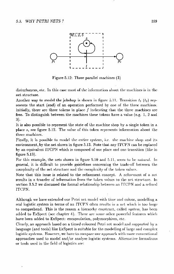
5.3. WHY PETRINETS ? 189
1MTz::r-----, I ' ' s I I I
I
Pt I I
I t I
L---------J Figure 5.12: Three parallel machines (3)
disturbances, etc. In this case most of the information about thc machines is in the net structure. Another way to model the jobshop is shown in figure 5.11. Transition t 1 (t 2 ) represents the start (end) of an operation performeel by one of the three machines. lnitially, there are three tokens in place f indicating that the three machines are free. To distinguish between the machines these tokens have a value (e.g. 1, 2 and 3). It is also possible to represent the state of the machine shop by a single token in a place s, see figure 5.12. The value of this token represents information about the three machines. Finally, it is possible to model the entire system, i.e. the machine shop and its environment, by the net shown in figure 5.13. Note that any ITCPN can be replaced by an equivalent ITCPN which is composed of one place and one transition (like in figure 5.13). For this example, the nets shown in figure 5.10 and 5.11, seem to be natura!. In genera!, it is difficult to provide guidelines concerning the trade-off between the complexity of the net structure and the complexity of the token valucs.
Note that this issue is related to the refinement concept. A refincrnent of a net results in a transfer of information from the token values to the net structure. In section 3.5.2 we discussed the forma! relationship between an TTCPN and a rdined ITCPN.
Although we have extended our Petri net model with time and colonr, modeHing a reallogistic system in termsof an ITCPN often results in a net whiclt is too large to comprehend. This is the reason a hierarchy construct, called ·'Yslem, has been added to ExSpect (see chapter 4). Thcre are some other powerfut features which have been added to ExSpect: encapsula.tion, polymorphism, etc. Clearly, an approach basedon a timed coloured PetJ·i net model and supportcel by a language ( and tools) like Ex Speet is suitable for the modeHing of large and corn plcx logistic systems. However, we have to comparc our approach with more convcntiona.l approaches used to model and/or ana.lyse logistic systems. Alternative forrnalisms or tools used in the field of logistics are:

190 CHAPTER 5. MODELLING LOGISTIC SYSTEMS
. er . I t I ... ___________ J
Figure 5.13: Three parallel machines(4)
data models (ER, relational model)
data flow models {ISAC, SADT, DFD)
analytical models (QN, LP, DP)
simulation languages (SIMULA, SPSS)
specific simulation packages (SIMFACTORY, TAYLOR)
Data models are used to describe complex state spaces, for example a database scheme for an MRP system. Some well-known data models are the entity relationship model (Chen [29]) and the relational model (Ullman [119]). A drawback of these models is the fact that they only describe the static data aspect of a system, i.c. thcy fail to describe the dynamic structure of a system.
There are several informal frameworks to describe data flow, often using graphical languages. Frequent used frameworks are SADT {Marca and McGowan[79]), ISAC (Lundeberg et al. [78]) and DFD (Ward and Mellor [121 ]). Most of these frameworks also have methods to describe the data structure. The result of using such an approach is an informal description, that does not allow for quantitative analysis.
Analytica] models are mathematica! models such as, a queueing model, a linear programming model, a dynamic programming model, etc. Sometimes, we have to simplify the problem statement to be able to use these models. Moreover, modelling a 'rcal' system in termsof such a mathematica! model is often quite ditHeult and requires expert consultation.
We tlistinguish between two kinds of simulation languages: (1) general purpose programming languages and {2) block-oriented languages. Examples of general purpose programrning languages suitable for simulation are: SIMULA (Dahl and Nygaard [3:3]) or more conventional languages with libraries of subroutines. Most block orientcd languagcs are ba.<~ed on queueing networks. Examples are SLAM, Q-GERT, SAlNT and SIMAN (see Pidd [103]). These languages are flexible and quite fast.

5.3. WHY PETRINETS? 191
data data
models flow models
Ex Speet
si mulation specific
languages si mulation packages
Figure 5.14: ExSpect compa.red withother tools
However, they are hard to customize, not user friendly a.nd it takes great effort to implcment a model. Note that we speak a.bout implementa.tion rather tha.n specification.
Finally, there are specific simulation packages. These packages are a.pplica.tion specific. Examples are SIMFACTORY a.nd TAYLOR (Pidd [103]). Most of these packages simulate the internal behaviour of a production unit. These packages are easy to use and have animation facilities. The fa.ct that they are tailored towa.rds a. specific application makes them inflexible.
Our claim is that ExSpect combines the adva.nta.ges of these alternative approaches, as shown in figure 5.14. A token in ExSpect can have a.n a.rbitrarily complex type. We are working on the integration of a new data model into our fra.mcwork (sec Van Hee and VerkouJen [58]). Our system concept and tbc design interface support 'dataflow-like' diagrams. This is very useful in the carly modeHing phases. Note that we support hierarchical decomposition, cornpa.rablc to SA D'J' ( Marca. a.nd McGowan [79]). The module concept a.llows for tbc dcvelopnwnt of doma.in specific libraries containing generally applicable building blocks. These huilding blocks !.end to be very gencric because of polyrnorphism a.nd pa.rametcri;.mtion. Tlw spccification language is very expressive allowing for spccia.l purpose consl.ruct.s, this wa.y it is possible to specify parts of the system not covered by sta.ndard huilding hlocks. The tooi ExSpect is easy to use beca.usc of a nJousc orient.cd inl.<'rfa.n· wit.h 'pop-up' menus. Besides simulation, we a.lso support static type clwcking a.nd sc•vC'ra.l a.na.lysis

192 GRAPTER 5. MODELLING LOGISTIC SYSTEMS
techniques (e.g. simulation, invariants, MTSRT, etc.). These analysis methods are possible, hecause we use a forma! framework which is based on Petri nets (which have a firm mathematica! foundation). We think it is also possible to use the ExSpect specification as a starting point for analysis using mathematica! techniques such as, dynamic programming, linear programming, Markovian analysis, etc. (see Wessels [122] and [123]). To use these analytica! models it is often necessary to restriet ourselves to a limited set of specifications. Consider for example a specification composed of the queueing components described in section 4.5. Such a specification may be analysed using analytical techniques developed for queueing networks. Another example is the use of an ExSpect specification of a distribution network, as input for a linear programming model. In this case, the ExSpect specification is used as a 'blueprint' (i.e. a detailed description) of the logistic system. Suitahle projectionsof such a hlueprint may allow for analysis using mathematica! models. Clearly, the integration of these analytica! models into our framework requires a considerable amount of research.
Additional advantages of ExSpect are the open architecture, the software and the possibility to conneet several runtime interfaces (running on different machines) to an interpreter; all interading with the same si mulation (ideal for training purposes ). See chapter 4 for more information about the features of ExSpect.
Considcring the requirements for a specification language for (discrete) logistics, it may be concluded that ExSpect is a sensible choice for the modeHing and analysis of logistic systems. However, other Petri net based tools (e.g. CPN [71]) or approaches based on process algebra (see Biemans and Blonk [20] and Mauw [85]) are worth considering. See chapter 1 for a. discussion on this subject.
5.4 Structuring logistic systems
In the area of logistics many hooks are ava.ilahle, nearly all of which deal with the control and design of production, inventory and transport systems. These hooks reflcct the fact that research in the field of logistics developed along two separate !i nes. The first line concentrates on solving mathematica! problems related to logistics. lnvestigations in this area are part of a discipline called operations research. The models used in this discipline are elegant and allow for powerful methods of analysis. llowever, it is often difficult to model a real system in termsof such an analytical model. Therefore, the problem statement is often simplified to allow for analytica! solutions. Consicier for example the application of queueing networks to scheduling problems and the application of linear programming to transport planning. Although these analysis methods help us gain insight in the problem, they can only be applied in rather specific situations or require expert consultation. Moreover, somc of the results reported in this area describc techniques for problems that do not even cxist.

5.4. STRUCTURING LOGISTIC SYSTEMS 193
The second line of research concentrates on practical logistic problcms. The results are often qualitative and informal. The approaches used in this area are mainly discipline oriented, i.e. they focus on a specific aspect of logistics. Examples are the research on customer service, storage equipment, communication facilities (EDI), persounel requirements, etc.
Both of these lines did not lead to a complete and comprehensive model of logistics. Recent literature in the field of production control stresses the need for a systematic approach to production planning and control (Bertrand, Wortmann and Wijngaard [18], Biemans et al. [21], [19]). In [19], Biemans attempts to structure manufacturing planning and control using a 'reference model', i.e. a representation of an idealized production organization, defining the tasks of the componcnts as well as the interactions between the components. In [18], Bertrand et al. describe a number of general concepts for the design of production control systems. In our opinion, there is also a need for a systematic approach to logistics. The main reason to structure logistics is the growing complexity of the control problems in logistics. This complexity is partly caused by the total cost concept, described in this chapter, which forces us to consider the entire logistic chain. Another reason for the increased complexity is the progress in information technology allowing for more sophisticated management systems.
In this chapter we structure the field of logistics by making a first step towards a comprehensive 'reference model' for logistics (see also [4] and [.5]). To realize this, we use a systematic approach based on concepts from systems analysis (see scction 4.2.4). Similar approaches have been developed for other application domains, e.g. in [35], De Leeuw uses a systems approach to structure organiz;a.t.ion theory. Our approach is intentionally abstract. Therefore, we focus on the main logistic functions (e.g. transport, demand, supply, production and stock holding) and ignorc aspects like administration, safety, personnel, etc. Moreover, sometiJHcs we abstract from the physical reality, i.e. we are not interested in the actual layout of a logistic system, mechanica! aspects, communica.tion protocols, etc. To structure logistics, we identify and specify typical flows and a.ctivities in thc context of logistics. This results in a. ta.xonomy of the logistic flows and a forma.! definition of a logistic system. This forma! dcfinition is a first step towards a comprehensive reference model for logistics. The term 'refcrcncc model' was introduccd by Biemans in [19] and [21]. A refercnce model describes a complex system as a configuration of intera.cting subsystems ( components) tha.t ea.ch cxecutc a specific task. Compared to the reference model for manufacturing planning aml control, described in Biemans [19], our approach is more forma! (and abstract) a.nd a.ddresses another application domain. Based on our definition of a logistic system, we have dcveloped a. logistic libra.ry, that will bedescribed in section 5.0. The predefincd components in this libra.ry ar<' forma! specifications of the logistic subsystems idcntified in this sedion.
To structure the field of logistics we start with a. taxonomy of til<' flows insidc a.

194
flow
GRAPTER 5. MODELLINO LOGISTIC SYSTEMS
information 2.----__ ..,..master/slave 2.1 production control 2.1.1
interactions ' production planninr, 2·1.
2
mventory control 2· ·3
inventory plannin~ 2·1.4
transport routing .1.5
transport planning 2·U3
I. I 2 2 c. 1ent se~ver · request 2.2.1
mteractlons ~ ~ response 2·2·2
reports 2·3
administrative information 2.4
Figure 5.15: A taxonomy of the flows inside alogistic system
logistic system. Figure 5.15 shows our taxonomy, the arrows should be interpreted as 'is subtype of'. For example, the flow of goods is a subtype of the flow of resources.
Resources ( 1) are the physical or abstract ob jects in a system. We distinguish bet ween goods (1.1) and means (1.2). Goods are the materials, components and products flowing through the logistic chain. In general these goods are physical objects. Examples of non-physical goods are bank accounts or reservations, we call these objects abstract objects. The resources needed to create, maintain or distribute both kinds of goods are called means, e.g. machines, tools, trucks, manpower, etc. Mcaus are employed, but not consumed like materials. Sametimes we use the term capacity resom·ces to refer to these means. It is hard to draw a strict dividing line hetween goods and mea.ns, think for example of a tooi in a machine that wears off significantly when it is used. In genera!, means are active and goods are passive resources.
We use the term information (2) for all other kinds of interaction. Information can bc characterized by: 'all the messages needed to get the right quantity of goods at the right time at the right place'. Information itself is not an object to pursue. In most cases informa.tion is kept to a minimum. We divide the class of information flows int,o four subclasses: maste1jslave intemctions (2.1 ), clientjser·ver interactions (2.2), ·rqw1·ls (2.3) and administmtive infonnalion (2.4).

5.4. STRUCTURING LOGISTIC SYSTEMS 195
Master/siave interactions are the messages exchanged between a control system (master) and a subordinate system (slave). The master sends comrnands to the slave and the slave sends some status information to the master. Essential is the fact that their relationship is not based on equality. Examples of such interactions are: (real-time) production control (2.1.1), production planning (2.1.2), inventory control (2.1.3), inventory planning (2.1.4), transport routing (2.1.5) and transport planning (2.1.6). For the moment this classification is self-explanatory. Although our classification of master/siave interactions is not exhaustive, we think it covers most control interactions encountered in logistics. We will return to this subject in section 5.5.
Client/server interactions are ba.sed on the equality of both parties involved. An alternative term for elient/server interactions is coordination. Coordination is based on requests and responses instead of commands and status information. The elient sends a request (2.2.1) toa server. Typical requests are: the ordering of goods and services, inquiries about the charges and the reservation of capacity resources. Notc that pla.cing an order with a supplier is a request rather than a command. A request is always followed by a response (2.2.2) from the server io t.he diPnt. There are two kinds of requests and responses: withand without a 'commit.'. A request without a commit means that the dient only inquires about some service or goods. Otherwisc (with commit ), the request is satisfied by the server if possiblc. In this case thcrc is response with a commit indicating that the server will deliver th(• requested service or goods. In all other cases there is a response without a commit. Note that this classification conforms with the ideas emerging from the field of Electronic Data Interchange (ED I).
Finally, we have the Hows of reports and adrninistrative information. These are thc information Hows not covered by the flows (2.1) and (2.2). A df'tailed description of these flows is beyond the scope of this chapter.
We introduce a graphical convention to denote these flows: flows of resources are represented by a double arrow and flows of information are rf'pn·sented by single arrows. To distinguish flows of means from ftows of goods, we represent flows of means by dashed double arrows. Client/server interacHons are also represented hy dashed arrows. All other flowsof information are represented by an ordinary arrow. Figure 5.16 shows these graphical notations. This cond1Hies our taxonomy of the flows inside a logistic system. In section .5.5 wc will show how to model these flows in terms of ExSpect types.
Figure 5.16 shows the general form of alogistic systern. The behaviour of a 'real' logistic system is often too complex to comprehend, therefore we propose a i op down approach. This approach deals with the complexity by decomposing the logistic system into subsystems. Each of tlwse subsystc·rns rel>res<•nts a s<'paratc logistic process with a distinct task in the context of the OV<'rall system. lt is possibiP to repcat this process until the lowest lev('] is reaclt<'<l. At th<· lowest level there ar<' three kinds of systems:

196 CHAPTER 5. MODELLINO LOGISTIC SYSTEMS
____ _, ..,__ ___
rnaster/siave 2·1
interactions
1f 11 11
11
LS
"
rneans 1.2
-~
Figure 5.16: A logistic systern
• physical elementary systems (PES)
• information elementary sy.qtems (lES)
• control systems (CS)
- dient/server 2·2
interactions
goods 1.1
Physical elernenta.ry systerns (PES) are systerns dealing with resources and are controlled by rnaster/siave interactions. Exa.rnples of PES are machines, automated guidcd vehicles and people doing manual work. Schematically a PES looks as follows:
===!ij•l >ES: IF======*' 11
This figure shows a 'typical' PES, e.g. it is also possible to have a PES without master/siave interactions or a PES which does not exchange means with its environnwnt.
Information elernentary systerns (lES) are systerns dealing only with information.

5.4. STRUCTURING LOGISTIC SYSTEMS 197
An lES is also controlled by master/siave interactions. Schematically:
~-----ttJ------IES ------ -----·
Examples of lES are demand forceast and order entry systems. An lES is controlled by some higher authority and communicates with other (information) systems via requests and responses ( elient/server interactions ).
Elementary systems (PES and lES) are controlled by a control system (CS). A control system controls subordinate systems via master/siave interactions and is controlled by master/siave interactions. Examples of CS are: reai-time controllers, MRP-modules and managers. In general an incoming command is translated into a number of commands for the subordinate systems. Schematically:
CS
Now we can give a recursive definifion of alogistic systcm (LS): a logistic system is an elementary system (PES or lES) or a set of logistic systems controlled by a control system (CS). Figure 5.17 shows an example of alogistic system. Our definition of a logistic system (LS) is summarized in figure 5.18. Physica.l clementa.ry systcms and information elementary systems are logistic systems. A group of logistic systems is a logistic system. One or more logistic systems controlled by some control system is also alogistic system. In [50], Van I-Jee and Somers use a similar recursive dcfinition of a production system.
Our top down approach produces a hierarchy of systems. A logistic system, which is too complex to comprehend, is decomposed into a number of logistic subsystcrns. This decomposition process is repeated until the logistic subsystcms are consid<'rcd elementary.
The definition of a logistic systern sumrnarizecl in fignr<' 5.18 a.nd tlte taxonomy shown in figure 5.15 constitute a basis for a refcrrna model for logistics. The recursive definition of alogistic systPm tclls us how t.o de<·ompos<' a logistic syst<'Jll into meaningful subsystems, i.e. clecompositions have t.o meet tlw nitPria. st.a.tcd in figure 5.18. Basecl on these crit<'ria., W<' lind r<'la.t.ivcly indcpend<'nt. suhsyst.<'llls

198 CHAPTER 5. MODELLINO LOGISTIC SYSTEMS
r
CS
1 i I i I ~I!S
I CS I lES
PES f
= H PES . I
Figure 5.17: Alogistic system
PES = physical elementary system lES = information elementary system CS = control system
1
LS = PES I lES I LS-list I CS,LS-list
LS
-
Figure 5.18: A recursive definition of alogistic system
-----+
cxecuting a specific task and having a typical interaction structure. Expressing the interaction structure in terms of the flows identified in figure 5.15, helps us to find charaderistic components. Identifying a limited set of characteristic components, large enough to represent most of the logistic systems encountered in practice, yields a reference model. The development of a comprehensive reference model for logistics rcquires a lot of research and experience with the modelling of many real logistic systcms. We are convineed that this is possible, this is fortified by the existence of an informal reference model for production planning and control presented by Bicmans in [19].
Clearly, the development of such a reference model is beyond the scope. of the research reported in this monograph. lnstead, we give a short informal description of t.he typical logistic activities and control structures encountered in pra.ctice. In scct.ion 5.5 we will map the activities and control structures onto components specified with ExSpect. The result is a logistic library. With this this libra.ry we hope to attain a '80/20'-situation, i.e. a situa.tion where 80 percent of the components nee<k•d are already available in a logist.ic library and take up only 20 percent of your time. But the 20 percent you have to creatc yourself take up 80 percent of

5.4. STRUCTURING LOGISTIC SYSTEMS 199
your time. It is obvious, that it is not possible to attain this situation without a rigorous structuring of logistics. Moreover, the development of a library basedon a comprehensive reference model for logistics, would yield a situation where nearly all of the components needed are already available (e.g. a '94/15'-situation 1 ).
5.4.1 Typicallogistic activities
As stated, we confine ourselves to a short informal description of the typicallogistic activities and control structures. We start with a review of the primary logistic activities: (1) demand, (2) supply, (3) transport, (4) transformation and (5) inventory. The logistic library described insection 5.5 contains a component (building block) for each of these activities.
Demand
Demand is the trigger for all logistic activities (a.lthough demand may he stimulated by marketing). The demand for end-products is generated by a number of consumers. In our opinion the identity (or definition) of a consumer depends upon the scope of the logistic chain we want to consider. Suppose we have an audio manufacturing firm supplying a number of wholesale dealers. Each wholesale dealer supplies a number of retailers, and finally, each retailer sells audio equipmcnt to its customers. Depending on the scope of the logistic chain we want to consider, we define the wholesale dealers or the retailers 01' the customers to he the en ti ties that generate the demand. The demand (for a specific product) is often instabie and subject. to trends and seasonal patterns. If there is a frequent ordering of small quant i ties, we speak about independent demand. If there are only a few consumers ordering (n·latively) large quantities or there is a strong correlation between the cicmand for a number of products, we speak about dependent demand. It is often useful to classify the products demanded by thc consumcrs into thrL'<' classes: A, B and C. Class A contains products having a high demand, class IJ represents products having an 'average' demand, products in class C are ordered sporadically. In most situations a smal! percentage of thc procluc:ts account for a large percentage of the total demand, i.e. the products in class A repwsmt the main part of the demand. This classification process is often called A BC-analysis.
Supply
The supply process takes care of the input of raw mat<'rials and componcnts into thc logistic chain. The identity of a supplier also depcnds u pon the scope of the logistic chain we want to consider. The performance of supplier is mcasured in terms likc: lead time, variations in lead time, product quality, capacity and prire.
194 percent of the components needed are already availahle in a logistic lihrary and t.akc up only 15 percent of your time. But thc 6 percent you hav<' t.o cr<'a.t.<' yours<'lf take up 8ll percent of your time.

200 CHAPTER 5. MODELLING LOGISTIC SYSTEMS
Transport
Transport is a key factor in today's logistics. We distinguish between two kinds of transport: internal transport and external transport. Internal transport is the transport inside a plant or warehouse, external transport moves goods between plants and warehouses. This distinction is not absolute, for example it is difficult to classify the transport between two production units. Thc forklift truck is the most popular transportation aid in internal transport. It is often used in conjunction with pallets. Next in popularity is the conveyor. Conveyor systems are particularly useful for moving items along a fixed route. There are a number of different conveyor types (wheel, roller or belt) to accommodate specific needs. A relatively new way to transport matcrials inside a building is the Automated Guided Vehicle (AGV). There are five basic transportation modes for external transport: rail, highway, water, pipcline and air. Each transport mode has its own characteristics. For example, transport via water is slow but cheap for high volumes, transport via highways is more expensive but faster and more flexible. The selection of transport mode depends upon the products to be transported, required speed, locations and casts. Note that from a modeHing point of view the transport mode is not important, only the relevant charaderistics matter.
Transformation
A transformation process uses one or more resources to produce one or more (possibly different) resources. One can think of a step in a manufacturing process or the servicing inside a bank or hospita!. The two main charaderistics of a transformation procèss are the speed and capacity. Note that a step in a manufacturing process may result in a converging or diverging flow of goods. For example, an assembly process combines several types of products into one product. Remember that we distinguish between two kinds of resources: goods and capacity resources ( means ). If a number of transformation systems share a capacity resource, we speak about a shared resource. Examples of shared resources are: manpower, machines, etc.
Inventory
Inveutories are needed for a number of reasons:
Production needs Warehousing may be part of the production process beeause certain products require a period of aging. For example, painted products have to dry and cheese has to age.
Coordination of supply and demand If there is a seasonal demand or production, then supply and demand have to be coordinated. For example, canned

5.4. STRUCTURING LOGISTIC SYSTEMS 201
fruits have a constant demand and a seasonal production. Therefore, companies producing canned fruits have to stockpile production output in order to meet the demand during the rest of the year. To guarantee a fast delivery, if necessary, end-products are stored close to the customer.
Costs Transportation of large volumes is relatively cheap. Production in large batches reduces the production costs. Therefore, it is sometimes possible to reduce transportation or production costs by trading them for warehousing costs.
lnside a production process there are buffers to allow machines to continue working while another machine undergoes maintenance, tooi changes, or repairs. The matcrials contained by these buffers are referred to as in-pmce,<;s inventory.
Inventory ties up capita!, uses storage space, deteriorates and sometimes becomes obsolete. Therefore, the main objective of inventory management is to minimize the inventory without disturbing the production or distribution process. To conclude, we mention that there are two alternative interpretations of inventory: 'transport with speed zero' and 'transformation in time'.
5.4.2 Typical control structures
We de:fine logistics control as the coorclination of the logistic activities to achieve a speci:fic external performance at minimum costs. This coordination is often difficult, because there are conflicting objectives. For example, economie objectives are often in conflict with customer service objectives or flexibility objectives. One way to avoid sub-optima! control is to centralize the control function. However, it is hard to centralize the control of a. complex logistic without. a large in vestment in information systems. lnstead of a centralîzed approach it is also possible to create self-contained activities. Vsing self-contained activitics simplifies the control function. A hierarchical approach combines the a.dvantages of a. centra.lized control and self-contained units. The application of a hierarcbical approach t.o production control is advocated by a number of authors (see Meal [87] and Eertrand at al. [18]). We distinguish four typical control structures in logistics: ( 1) local control, (2) push control, (3) pull control and (4) integral controL We will show that these control structures fit in the framework described in this section. At the same time, wc illustrate that it is possible to use this framework to express reecut dcvelopments in logistics (e.g. JIT, MRP, DRP, BSC, Kanban).
Local control
A classica! approach towards logistics control is the crcation of a ('Ompletcly sclfcontained units. Such a unit is only driven by the arrival of goo<ls. This situatiou is depicted in figure 5.19. Many intcrmedia.te steps in a. ma.nufa('t.uring proccss have 'loca.l control'. An example of such a. process is an a.ssemhly couveyor.

202 CHAPTER 5. MODELLINO LOGISTIC SYSTEMS
I CS I 1 r
LS
Figure 5.19: Local control
Push control
A set of successive logistic activities is controlled by 'push con trol', if the first activity is controlled by a master plan and all intermediate activities havealocal control ( see figure 5.20). This master plan is based on demand forecasts and initia! inventories. This kind of control is easy to realize but it suffers from a number serious drawbacks: low flexibility and large inventories or a poor delivery performance. These drawbacks are the result of the absence of reai-time feedback from the demand. Examples of 'pure' push systems are found in the field of continuous production, engineer-to-order and production-to-stock (driven by forecasts) systems.
LS
Figure 5.20: Push control
Pull control
A 'pull system' is a system where all activities are triggered by demand (see figurc 5.21 ). Pull controlled systems are demand driven: a production or supply action is issued at the moment a product is requested or inventory is below a given value. The classica! inventory management systems, often referred to as Statistica! lnventory Coniml (SIC) systems, are examples of pull systems. The objective of these systems is to replenish stocks at the 'right moment' in the 'right quantity'. Therc are basically two ways todetermine when to order: (1) order at the moment the stock falls below a (fixed) minimum level called the order point (B) or (2) check the inventory periodically, i.e. if stock is below a. certain level (s), a replenishment order is issued. There are two ways to determine the quantity: ( 1) a fixed quantity

5.4. STRUCTURING LOGISTIC SYSTEMS 203
Figure 5.21: Pull control
(Q) or (2) a quantity depending on the current operating stock (8). An example of an (s,S) inventory management system is a system checking the stock at the end of every month and the order quantity is the difference between a predefined maximum level and the current operating stock.
We already mentioned a number of reasans for the existence of inventory. Somc of these reasous are in conflict with the .lust-In- Time ( JIT) philosophy. The goal of the JIT approach is to reduce inventories ('zero inventory') and waste ('total quality control') by obtaining or producing, just what is needed, just when it is needed. Removing excess inventory and inspeetion fm·ces problems to sm-face. The .JIT approach tries to solve these probieros continuously. The rise of JIT is closely related to the successof the Japanese industry and the development of the Kanban production system. The Kanban system, developed at the Toyota Motor Company, uses a pull controL This pull control is implemented using two kinds of cards (kanbans): withdrawal (or transport) kanhans and production kanbans. The withdrawa.l kanban shows the quantity of products that the subsequent process should withdraw from the preceding one. The production kanban shows thc quantity that the preccding process should obtain or produce.
free frec production withdrawal
---j A ~ ~n~~~ j
I ~k:·~'~" j
B t---production wîthdrawal
kanhans kanhans
Figure 5.22: A kanban system
Consider, for example, we have a process A followcd by a process IJ as stmw11 in ligure 5.22. Products flow from process A to process B via a store /. IHitially thcre are a number of free withdrawal kanhans in Band a nnmbcr of free production kanbami in A. Process A produces the prodtKts associaü•d with the production kanba.ns,

204 CHAPTER 5. MODELLINO LOGISTIC SYSTEMS
atta.d1es the kanhans to these products and stores them in the storage location. Process B takes a free withdrawal kanban to the storage location (/), withdraws the required number of products, detaches the production kanban and attaches the withdrawal kanban. The withdrawal kanban becomes free if the corresponding products have been used by process B. Note that this way the in-process inventory is limited by the number of kanbans. The JIT philosophy aims at a continuons rednetion of the number of kanhans by improving the production process. There are a number of alternative kanban systems, for example, a kanban system with only one type of cards ( kanhans ).
The Kanban system of in-process inventory control works particularly well in situations with small batches and a continuons demand. lloth the JIT approach and the introduetion of the Kanban system require set-up time reductions, improved quality control and employee involvement and flexibility. Note that information processing hardly plays a role.
Integral control
LS
Figure 5.23: Integral control
The increasing availability of computing power stimulated a more centralized approach towards logistics controL Such a centralized control is used to integrate the control of a number of logistic processes. Examples of integral control are: MRP (Materials Requirements Planning), MRP-11 (Manufacturing Resources Planning), OPT (Optimized Production Technology), BSC (Base Stock Control), DRP (Dist.ribution Requirements Planning) and DRP-II (Distribution Resources Planning). Other examples of integral control are found in the field of computer aided manufactming (CAM) and flexible manufacturing.
Pcrhaps the most widespread form of integral control is Matcrials Requirements Planning (MRP). MRP produces a production schedule given: (1) the Bill-OfMaterials (BOM), (2) current inventory, (3) lead times and expected demand for fiual prodncts (Master Production Schedule). The Bill-Of-Materials (or goes-into graph) is a graph specifying the required prodncts a.nd materials needed in each production step. This combincd with the production lead times allows MRP to

5.4. STRUCTURING LOGISTIC SYSTEMS 205
'explode' the requirements into a production and purebase schedule. The MRP mechanism has been extended in several ways: safety stocks, minimal batch sizes, failure rates, etc. A serious drawback of MRP is that it does not take capacity constraints into account. This is the main reason for the development of Atanufacturing Resources Planning (MRP-II). MRP-11 checks whether it is possible to meet the Master Production Schedule (MPS) using a rough-cut capacity planning. If there exist serious capacity bottlenecks, the MPS is repeatedly adapted until the MPS is feasible. Using the MPS, it is possible to anticipate a future trend and to balance the load on bottleneck machines. Note that the MPS is no longer a direct translation of external demand. Figure 5.24 shows the two level control hierarchy of MRP-II.
I CS ( determine MPS) I I r
~ 1 I - lES I CS ( detailed scheduling) I --
r ! r ! LS LS LS I I
Figure 5.24: MRP-II
OPT is an approach basedon a scheduling system. The maiu charaderistic of this approach is the emphasis on the efficient use of bottlenecks.
Dist1·ibution Requirements Planning (DRP) is a technique to determinc when, where and how to replenish in a distribution network. A typical distri bution network controlled by DRP consists of factories, a central warehouse, regional warehouses and retailers. DRP uses: (1) current inventories at each location, (2) transport and handlîng times and (3) expected demand at each location, to clcterrninc a rcplenishmenL plan. This plan tells how and when products should be moved amoug the various locations in the distribution network. DRP a.pplics the MRP priuciples aud techniques to distribution instead of production. Distribution Requirements Planning is often used in combination with MRP, in this case DRP generates tbc MPS. H is also possible to extend DRP to Distribution Resourcc.5 Planning (DRP-II). DRP-II checks whether the distribution system can handle the generated plan. lf not, thc plan is revised until all capacity constraints are satisfied.
Another way to manage inventories is Base Stock Conlml {BSC). BSC is dosdy related to Statistica! Inventory ControL In a BSC sysiem all warehouses are aware of the actual demand and the stock levels of the warehouses 'downstream'. Iu case of a central warehouse supplying a numhcr of n·gioual wa.r<~houses, t he central

206 GRAPTER 5. MODELLING LOGISTIC SYSTEMS
warehouse knows the actual demand and the stock levels of the regional warehouses. BSC reduces the total inventory in the distribution system and is not subject to shock waves of unexpected demand.
IJ CS I 1 r 1 r 1 r
I M I I M I I M I IT ll IT il IT [
J T I
Figure 5.25: A Flexible Manufacturing System (FMS)
Inside a production unitor warehouse there are all sorts of integral controL Think for example of the scheduling of a jobshop or a Flexible Manufacturing System (FMS). An FMS is formed of a set of flexible machines, an automatic transport system and a sophisticated control system to decide at each instant what has to he clone on which machine. Figure 5.25 shows a schematic view of an FMS, the subsystem named T represents the transport system, the subsystems named M represent the machine cells. Note that a product follows a route which is not restricted by the physical layout of the shop floor.
This completes our brief review of existing control techniques in logistics. For more information on production control, the reader is referred to Biemans [19], [21], Hertrand et al. [18], Fogarty and Hoffmann [42]. Although many of the ooncepts for production control apply to logistics con trol, the management of inventories and transport requires some more attention. Therefore, we focus on the location of invcntory and typical distribution structures in a logistic system.
A way to characterize a logistic system is to identify the location of inventories. In thc field of production logistics we see three typica.l structures: (1) make-to-order, (2) asscmble-to-order and (3) make-to-stock. In a make-to-order situation, the production of a product starts at the moment an aetual demand occurs. In this case therc is no inventory of finished and semi-finished products. In a make-to-stock situation, demand for fi.nished products is sufficiently large to allow for production in advance of actua.l demand. Assemble-to-order means that subassemblies are manufadured in advance and the assembly of end-products starts on the basis of actual dcmand. These t,hree situations can be defi.ned in termsof the location of the so-called decoupling points. A decoupling point holds inventory to decouple demand from production or supply. This inventory is replenisheel by a planned production or delivery.

5.4. STRUCTURING LOGISTIC SYSTEMS
Figure 5.26: A typical distribution structure
regiona.l warehouse
207
Products are withdrawn from this inventory on the basis of actual demand. For example, a make-to-stock situation is characterized by a customer order decoupling point, which is near the customer and holds end-products.
In the field of physical distribution there are three typical structurcs: (1) elired delivery, (2) a central warehouse and (3) regional warchouses. In the direct delivery distribution structure, products are supplied directly to the custorners without holding inventories in separate warehouses. Sometimes a number of fa.ctorics supply a central wa.rehouse. This central warehouse supplies the customers. To provide a specified level of customer service these distribution structures utilizc high-speed transport. Another possibility is to create a number of regiona.l warehouses close to the customers. Figure 5.26 shows a distribution structure with onc central warehouse and a number of regional warehouses. The flow of goods is rcprcscnted by double arrows, the flow of information is represented by single arrows. Note, that this figure does not specify what kind of information (master/slave interactions, elient/server interactions, reports or administrative informa.tion) is cxchanged hetween the various locations.
For more information on logistics control we rt>fer to Bowersox [2,1], Fogarty and Hoffmann [42].

208 GRAPTER 5. MODELLINO LOGISTIC SYSTEMS
method
logistic
8 library
Figure 5.27: The proposed logistic framework
5.5 A logistic library
llased on the approach described in the previous section, we have developed a small logistic library. This library contains a number of generally applicable logistic componcnts.
In scction 4.4 we discussed the purpose of such a domain specific library. The two main reasans to develop a logistic library are:
• a logistic library facilitates and speeds up the modeHing process
• a Iogistic library can he used to capture and distribute logistic knowledge
However, for the logistic application domain, a logistic library is not sufficient. To support the use of the library, we have to supply a method. This method tells you, how to use the logistic components (see figure 5.27). We have developed a rather simple methad basedon the approach described in the previous section. This method is outlined in section 5.6. llasically, our logistic library consistsof two parts: (1) a number of type definitions to model the flowsof resources and information, and (2) a number of generic system definitions to model typicallogistic activities. The type definitions are basedon the taxouomy shown in figure 5.15. Because of the graphical nature of ExSpect, we use the term 'component' or 'building block' to denote a predefined system definition. Wc have used the definition of a. logistic system shown in figure 5.18, to identify useful componcnts. Th is implies that a component is: ( 1) a physical elementary system, (2) an information elementary system, (3) a control system, (4) a system composed of a set of relatively independent logistic components, or (5) a system composcd of a set of logistic components controlled by a control system.
Thc usefulness of the logistic library highly depends u pon the utility of the individua.l components. A building block (component) is considered to be useful if it is:

5.5. A LOGISTIC LIBRARY 209
• easy to use
• powerful
• flexible
• robust
A component is easy to use, if it is easy to understand its semantics and there is a straightforward relation with the world we want to model. This is only possible if the component represents a typicallogistic activity with a relatively independent task. The modeHing power of a library depends on: (1) the expressive power of the building blocks (is it possible to model something?) and (2) the average size of a model in terms of the building blocks. Note that it is possible to have building blocks allowing for the modeHing of a large class of systems, but in a roundabout way. Compare this to programming in assembler, it is possible to program anything, but it takes a lot of effort. The flexibility of a component also depends on two aspects: (1) is it easy to adapt the component and (2) are t.he important characteristics of a component para.meterized. Parameterized building blocks are useful, because they can be tailored for a specific situation, i.e. paramcterization is used to make a component generally applicable so that it can be used in a wide variety of applications. Finally, a building block has to be robust in t.hc sense that it can handle various inputs, i.e. the number of assumptions about the environment of the component has to be as small as possible.
Besides the usefulness of the individual components, the concept na! integrity of the library is important. This means that it has to be possible to composc components into a system having a 'natura\' structure.
The logistic library described in the rest of this chapter tries to maxirnize the five objectives: easy to use, powerful, ilexible, robust and conceptual integrity. Note that some of these objectives may be contradictory. Our goa.l is not to present an exhaustive list of logistic components covering all situa.tions encountercel in logistics, but to show that it is possible to create a comprchensivc sd. of gencric logistic building blocks. Our aim is to capture logistic knowlcdge in this library and to validate the '80/20-situation' described in the previous section.
The library we propose is hierarchical, i.e. some of the building blocks are composcd of other building blocks. ExSpect supports the user of this lihra.ry in making his own building blocks from already existing ones. Tllis way tlw user is enabled t.o make complex hierarchical models with a lot of levels. Thereforc, wc provid(~ wmc guidelines: (1) the number of levels in the hierarchy (visible t.o tlw user) shotdel he smaller than 6, (2) the number of different building blocks a.t. the sarne level (in a subsystem) should be smaller than 10. In otlter words: avoid a shallow or extremely deep hierarchy. Note that these figures are only guidelines, t.IH~Y depend on the system to be modelled.

210 GRAPTER 5. MODELLING LOGISTIC SYSTEMS
type id from num; type location from str; type prod from str; type oparation from str; type capacity from real; type timewindow from real >< real; type commit from bool; type conditions from real; type age from real; type material from prod -> real; type task from oparation >< capacity;
i type route from (num -> (location >< $task)) >< num;
Table 5.1: Somebasic type definitions
. route
I num location $ task num oparation capacity
i 1 'EindhovenDC'
I
2 'ParisPU8' 'drillingFA8' 2.55 'grindingDR7' 1.08 'grinding;RT6' 1.29 2
!
3 'LyonPU9' 'paintHG9' 4.93 'polishiR7' 0.08
. 4 'MadridDC'
Table 5.2: A value of type route
5.5.1 The type definitions
Insection 5.4 we presented a taxonomy of the flows inside alogistic system. We will use this to classify the type definitions used by the logistic building blocks. A list of basic type definitions is given in table 5.1. Thc type material is a mapping from products (prod) to reals representing the quantity of each product. The type timewindow is used to denote an interval of time. Another interesting type is the type route. A route is a list of pairs and a pointer pointing to a pair in the list. Each pair is formed of a location and a set of tasks. The pointer is used to id<'ntify the current location and the tasks to be executed at this location. Note that the list is implemente<l as a mapping from num to location >< $task. Table 5.2 shows a value of type route. We have defined some standard fundions for this type:

5.5. A LOGISTIC LIBRARY
1.1 type goods from id >< route >< material; 1.2
type means from id >< (operation -> capacity) >< age; 2.1.1
type realtimeprodcommand from material >< means >< task >< material; type realtimeprodsignal from material >< $means; 2.1.2
211
type aggprodcommand from prod -> ((timevindov -> real) >< conditions); type aggprodsignal from (prod >< timevindov) -> real; 2.1.3
type delivercommand from goods; type receivesignal from goods; type stocklevel from material; type acceptedorder from goods >< timevindow; type replenishcommand from (prod >< timevindow) -> real; type replenishsignal from material; type ordervolume from ((prod >< timevindow) -> real). >< (material); type orderlimit from prod ->((timewindow -> real) >< conditions); 2.1.4
type replenishmentstrategy from prod -> (str >< real >< real >< real); type inventorylevels from prod -> (real >< real >< real); 2.1.5
type routecammand from (num -> (location >< $goods >< $goods)) >< means; type routesignal from means >< location; type availabletranscap from timewindow -> (operation ->
type acceptedtransorder from goods; 2.1.6
(capacity >< conditions));
type transportstrategy from str >< real >< real >< real; type transportperformance from real >< real >< real;
-2.2 type request from id >< route >< material >< timewindow ><
conditions >< commit; type response from id >< route >< material >< timewindav ><
conditions >< commit; - 2.3 type report from str;
-2.4 type admin from str; internal types
type billofmaterial from prod -> (material >< task);
Table 5.3: Some logistic type definitions

212 CHAPTER 5. MODELLING LOGISTIC SYSTEMS
export current[ x : route] := pil(x) .pi2(x)
: location >< $taak;
export atend[ x : route ] := all([i : dom(pi1(x)) I i <= pi2(x) ])
: bool;
export atstart[ x : route] := all([i : dom(pil(x)) I i >= pi2(x) ])
: bool;
export next[ x : route ] := pil(x).min(set([i: dom(pi1(x))
: location >< $taak;
export prev[ x : route ] := pil(x).max(set([i: dom(pi1(x))
: location >< $task;
i > pi2(x)]))
i < pi2(x)]))
All other types definition in table 5.1 are self-explanatory.
Table 5.3 shows some other type definitions, each corresponding to a specific kind of flow in a logistic system. The flow of goods is represented by the type goods. Goods flowing through the network have an identification, some routing information and some matcrials associated with it. Examples of objectsof type goods are: a truck load, a pallet, a parcel or a single product. Table 5.4 shows a value of type goods representing a set of parts, needed to produce a car with identification 897654. Note that currently the parts are located in Paris, where they have to he assembled. Object.s of type means have an identification, an age and a capacity for each kind of operation the object can perform. This type is used to specify capacity resources, such as machines, trucks, etc.
Client/server interactions are represented by objects of the type request and response. A request has an identification, a route, a contents (material), a time window, a condition and a commit field. The usual interpretation of a request is: 'can you deliver mesome matcrials within a time window, given some conditions'. If the comrnit field is 'true', then the request is automatically satisfied if possible. The condi ti ons field is used to specify the requested conditions, for exarnple maximal price or minimal quality. In all cases a request is foliowed by a response having the sa.mc identification. Thc oUter types (mainly master/siave interactions) wiJl be discussed when we describc the corresponding building blocks. Note that we chose 'the easy way out' to model reports and adrninistrative information.

5.5. A LOGISTIC LIBRARY 213
goods id route material
location $ task num r-----~--------~~
prod real oparation capacity
'EindhovenDC' 'chassis X 19' 'ParisPU8' 'drillingFA8' 2.55 'wheeiT45' 4
'grindingDR7' 1.08 'engineFMll' 897654 'assembleRT6' 1.29 2
'LyonPU9' 4.93 0.08
4 'MadridDC'
Table 5.4: A value of type goods
5.5.2 The supply system
The first building block we are going to describeis the supply system. The supply system is used to represent one or more suppliers taking care of the input of raw materialand components into the logistic chain. No te that a supply system (partly) defines the scope of the logistic chain we want to consider (i.e. the system boundary ), because in our library a supply system is the 'source' of materials. The header of the supply system is shown below:
sys supply[in request:request,
]
out response:response, outgoods:goods, val location:location,
expectedhandlingtime:real, acceptrule:(prod->((real><real)><conditions)), averagesupplydelay:(real><(prod->(real><real))), variancesupplydelay:real,
fun supplydelay[mu:real,sigma:real,r:real] :real
The system has one input pin (request) to accept requests for materiaL Th ere are two output pins: one to respond (response) and one to deliver the goods (outgoods). Note that we use the term 'pin' to refer to an input or output channd (place) of the system. The value parameters are used to spccify the (unique) location of the supply system, the average expectcd order lead tinw, somc accepta.ncc rules and the supply delay. The average supply delay is a fixed valHc per dclivery, and for each product a fixed delay and a variabie delay per item, as specified hy averagesupplydelay. The varianee of the di~tribution of the s11pply delay is given by variancesupplydelay. The distrihution of the supply delay is specified hy a

214 GRAPTER 5. MODELLINO LOGISTIC SYSTEMS
function parameter supplydelay. The arguments of this function are the average and varianee (calculated using the value parameters) and a random number. This way it is possible to specify any kind of distribution. A request for goods is accepted if the requested material is available in the period specified by the timewindow field in the request. The value parameter acceptrule specifies for each product, the period length, the maximum quantity available in each period and the supply conditions.
supplycontrol
acceptorders
1--_..,ro re o se
qoodssource ~----------~o
OU 0 d.s
Figure 5.28: The supply system
If we zoom in, we see that a supply system consists of three subsystems, see figure 5.28. The goedssouree system takes care of the actual production (or a substitute) and the delivery of the matcrials requested. The header of this system is given below:
sys goodssource[in dc:delivercommand, out outgoods:goods, val averagesupplydelay:(real><(prod->(real><real))),
variancesupplydelay:real,

5.5. A LOGISTIC LIBRARY 215
fun supplydelay[mu:real,sigma:real,r:real]:real ]
Note that the delay distribution of a delivery is specified by the value and fundion parameters that have been discussed for the supply system.
The subsystem acceptorders handles the requests for materials:
sys acceptorders[in ol:orderlimit, request:request,
J
out response:response, ao:acceptedorder, val location:location,
expectedhandlingtime:real
A request has an identification, a route, a list of materia.l, a time window, a condition and a commit field. If the commit field is 'false', then the request is an inquiry without any obligations. However, if the commit field is 'true', then the request wil! be satisfied if possible and the requesting party is obliged to accept the corresponding material ( or service). In both cases a response will follow having the same kind of attributes. If the commit field of the response is 'truc', then the material will bc delivered, in all likelibood within the timewindow, given the conditions requested. Note that such a response is only possible if the commit field in the request was 'true' and there are suffîcient resources to satisfy the request. To estimate the orderleadtime, the acceptorders system uses the value parameter expectedhandlingtime. The input pin ol of type orderlimit specifies the ordervolume that can be accepted for each period satisfying some minimal conditions.
The physical elementary system (PES) goedssouree and the information handling elementary system (IES) acceptorders are both controlled by the control system (CS) supplycontrol:
sys supplycontrol[in ao:acceptedorder, out ol:orderlimit, dc:delivercommand, val acceptrule:(prod->((real><real)><conditions))
]
The value parameter acceptrule specifies for each product the conditions (for cxample the quality or price of the product) and the maximum qua.ntity that eau be delivered in each period (the other field of type real is used to denote the length of the time interval). This value parameter is used to produc1~ tokens of type orderlimit to inform the acceptorders system ahout Uw maximal qua.ntity that can be supplied.

216 CI-IAPTER 5. MODELLING LOGISTIC SYSTEMS
5.5.3 The demand system
The demand for end-products is generated by a demand system. This system is a building block used to represent a class of customers. In a way the demand system is the complement of the supply system. This component defines the other end of the logistic chain we want to consider, because it is a 'sink' absorbing finished products. The header of the demand system is shown below:
sys demand[in response:response, ingoods:goods,
]
out request:request, val location:location,
suppliertable:(prod->((location->num)><conditions)), expectedorderleadtime:real, demand:(prod->((real><real)><(real><real))), requestedleadtime:real,
fun interarrivaltime[mu:real,sigma:real,r:real,t:real]:real, orderquantity[mu:real,sigma:real,r:real,t:real]:real
There is one output pin to order goods (request), and two input pins, one to receive goods (ingoods) and one to be informed about the requests (response). The location of the demand system is specified by the location parameter. The parameter suppliertable is used to determine where to order a specific product. The demand process is specified by the value parameter demand and the function parameters interarri val time and orderquant i ty. For each product demand specifies the average and varianee of the interarrival time ( the time bet ween two successive requests for the product) and the average and varianee of the orderquantity. These figures are used to calculate actual interanival time and orderquantity using the fundions interarrivaltime and orderquantity respectively. Both may depend on a random number ( r) and the current time ( t ). This way it is possible to model stochast ie distributions and seasonal trends. The parameter expectedorderleadtime is the expected time it takes to deliver a requested product. The parameter requestedleadtime is the maximal time between the moment the demand exists and the moment a demand is satisfied. Figure 5.29 shows the internal structure of the demand system.
The system goodssink accepts goods for the demand system and reports every delivery to the demand system via the output pin rs:
sys goodssink[in ingoods:goods,
J
out rs:receivesignal, val location:location

5.5. A LOGISTIC LIBRARY 217
dernandcontrol
i • qoocissink
Figure 5.29: The demand system
The demandcontrol system genera.tes the demand for products using the param~ eters demand, interarrivaltime and orderquantity. This results in a 'replenishment command'. The timewindow associated with the demand starts at the generated demand time and ends some time later, as defined by the parameter requestedleadtime.
sys demandcontrol[in rs:receivesignal,
]
out rc:replenishcommand, val location:location,
demand:(prod->((real><real)><(real><real))), requestedleadtime:real,
fun interarrivaltime[mu:real,sigma:real, r:real,t:real] :real,
orderquantity[mu:real,sigma:real, r:real,t: :real

218 CHAPTER 5. MODELLING LOGISTIC SYSTEMS
The procurement system has one output pin to order goods (request) a.nd two input pins: one to receive information a.bout a request (response) and one to accept replenishment commands (re).
sys procurement[in rc:replenishcommand, response:response, out request:request, val location:location,
suppliertable:(prod->((location->num)><conditions)), expectedorderleadtime:real
A replenishment command is a tahle specifying the demand for each product in a eertaio period. The procurement system tries to order these products using a strategy defined by the value parameter suppliertable. This table specifies for each product the minimal conditions (for example price or quality) the product has to satisfy and a preferenee list of suppliers (location->num). Note that in this context a supplier is a location able to deliver some products, for example a production unit, a distribution center or a supplier in a narrower sense (the supply component). The praeurement system triestoorder a. product at the location with the highest preference. If there are severallocations with the same preference, then an inquiry is done to find the best supplier (the commit field is 'false'). Otherwise, the inquiry is skipped and a.n order is sent to the supplier (the commit field is 'true'). If this first attempt does not give a supplier able to deliver the goods within the time window under the specified conditions, then the suppliers with the second best preferenee are consulted, etc. The value parameter expectedorderleadtime is used to time the requests.
5.5.4 The production unit
Thc pu system takes care of the transformation of products. One can think of a machine or a production unit. The header of the pu system is:
sys pu[in incommand:aggprodcommand, requestin:request, responsein:response, ingoods:goods,
out outstatus:aggprodsignal, responseout:response, requestout:request, outgoods:goods,
val bom:billofmaterial, reporttime:real, location:location, suppliertable:(prod->((location->num)><conditions)), expectedorderleadtime:real, expectedhandlingtime:real, initmeans:$means,
fun producefunction[demand:(prod><timewindow)->real, maxprodlevel:(prod><timewindow)->real,

5.5. A LOGISTIC LIBRARY
J
inprocessinv:material, freemeans:$means, busymeans:(means->(real><material)), bom:billofmaterial, time:real
] :($realtimecommand><$replenishcommand)
219
The input pin ingoods and the output pin outgoods represent the flow of goods between the production unit and its environment. If a production unit is unable to producesome material (for example raw materials), it triestoorder these using the requestout and reaponsein pins. The artual demand for products is handled using the request in and responseout pins. The pins incommand and outstatus are used to interact with some higher authority at the level of aggregated production plans. The time between two reports to this higher authority is specified by the value parameter reporttime. lt is obvious that a production unit has a location (location), a list of suppliers (suppliertable) and a hili of material (bom). Furthermore, a production unit has a nnmber a resources (in i tmeans ). For the pu system we assume that the number of resources is constant, it is easy to extend this to a variabie number of resources. The internal structure of thc pu system is shown in figure 5.30.
realtimecontroller
rocurem nt
iî.------------------------~ i o ds transfermerl-------o-r
0
o tg ds
Figure 5.30: The production unit

220 GRAPTER 5. MODELLINO LOGISTIC SYSTEMS
One of the subsystems is the following physical elementary system:
sys transformer(in pc:realtimeprodcommand, ingoods:goods, dc:delivercommand,
J
out ps:realtimeprodsignal, outgoods:goods, val location:location,
initmeans:$means
·This system receives commands of the type:
type realtimeprodcommand from material >< means >< task >< material;
Such a command specifies a transformation process transforming some material into some other material by executing a task using some means. The transformer system also accepts goods arriving via the input pin ingoods. Finished goods leave the system via outgoods. The release of finished products is initiated by a 'deliver command' via the input pin de. lf a task has been executed, this is reported via the output pin ps. Thc re al timecontroller system controls the procurement, acceptorders and the transformer system:
sys realtimecontroller[in incommand:aggprodcommand, ps:realtimeprodsignal, oa:acceptedorder,
]
out outstatus:aggprodsignal, pc:realtimeprodcommand, rc:replenishcommand, ol:orderlimit, dc:delivercommand
val bom:billofmaterial, reporttime:real,
fun producefunction[ demand:(prod><timewindow)->real, maxprodlevel:(prod><timewindow)->real, inprocessinv:material, freemeans:$means, busymeans:(means->(real><material)), bom:billofmaterial, time:real
]:($realtimecommand >< $replenishcommand)

5.5. A LOGISTIC LIBRARY 221
billofmaterial prod material task
prod re al operation capacity
'finishedcar MB2' 'carMB2' 1. 'paintCS3' 0.2345 'carMB2' 'wheelF3' 4. 'assemble' 7.6435
'chassisGl' 1. 'bikeFX3' 'whee!H2' 2. 'assemble' 5.3645
'chassisP 1' 1.
Table 5.5: A value of type billofmaterial
The controller receives commands via the input pin incommand of type:
type aggprodcommand from prod -> ((timewindow -> real) >< conditions);
This command specifies the maximum production levels for each period. The value parameter reporttime specifies the time between two successive reports. The behaviour of the realtimecontroller system is mainly specified by the function parameter producefunction. The demand parameter of this function represents the actual demand for each period, maxprodlevel gives the (maximum) production levels set by some higher authority, inprocessinv is the inprocess inventory, freemeans are the means ready to perform a task. The parameter busymeans represents the means that are performing a task, their expected termination time and the expected yield (material). The parameter bom specifies all production steps and is of type:
type billofmaterial from prod -> (material >< task);
Table 5.5 shows an example of such parameter. If a product is not in the domain of the mapping, then it has to be ordered, i.e. the realtimecontrollersystem sends a 'replenishment command' to the praeurement system. Note that the produeefunction returns zero or more commands for both the transformer system and the praeurement system. Using this function parameterit is possihle to implcment many production control methods (for example MRP). The realtimecontroller also controts the acceptorders systern, it spccifics thc maximum ordervolume that can be accepted for each period.
The building block pu distinguishes between aggregate production planning and detailed (real-time) production controL Inside the production unit jobs are schcdulcd for a specific machine (rneans), the outside world is not aware of the existence of machines. The same holds for the intermediate products nceded to produce an endproduct, for example sub-assemblies. The products controlled by the outside world are the so-called goods flow controlled items (sec 13crtrand et al. [18]). Typical prod-

222 GRAPTER 5. MODELLING LOGISTIC SYSTEMS
u cts to be controlled outside the pu system (i.e. via incommand and outstatus) are the MPS-items.
5.5.5 The stock point
In this section we describe a number of building blocks to model inventories. We start with the sp system, where sp stands for stock point. Examples of stock points are a regional warehouse, a distribution centre or a storage area containing supplies and raw materials. The main characteristic of our stock point is that it has a more or less autonomous behaviour. The header of the sp system is:
sys sp[in incommand:replenishmentstrategy, responsein:response, ingoods:goods, requestin:request,
]
out outstatus:inventorylevels, requestout:request, outgoods:goods, responseout:response,
val reporttime:real, location:location, suppliertable:(prod->((location->num)><conditions)), expectedorderleadtime:real, expectedhandlingtime:real,
fun replenish[s:replenishmentstrategy,physicalstock:material, demand:((prod><timewindow)->real), ordered:((prod><timewindow)->real)
]:replenishcommand, orderlimit[s:replenishmentstrategy,physicalstock:material,
demand:((prod><timewindow)->real), ordered:((prod><timewindow)->real) ]:orderlimit,
handleintime[x:material]:real, handleouttime[x:material]:real
There are four input pins and four output pins. The pins ingoods and outgoeds represent the flow of goods in and out of the stock point. If some external party needs some products, it sends a request to the stock point via the channel connected to request in. The stock point responds via responseout. The main objective of a stock point is to keep inventories of certain products, if the inventory level of a product falls below a certain levelor we want to anticipate on future developments, then a replenishment is needed. To order the products necessary for such a replenishment, we have the pins requestout and responsein. The replenishment strategy can he altered by some 'higher' authority via the incommand and outstatus pins. The meaning of tbc value and function parameters will be discussed when we describe the subsystems of sp shown in figure 5.31.

5.5. A LOGISTIC LIBRARY 223
•toekcontrol
replenlsh distribute
Figure .5.31: The stock point
The system stockcontrol controls the other two logistic subsystems replenish and distribute:
sys stockcontrol[in incommand:replenishmentstrategy, rs:replenishsignal, ov:ordervolume,
out outstatus:inventorylevels, rc:replenishcommand, ol:orderlimit,
val reporttime:real, fun replenish[s:replenishmentstrategy,
physicalstock:material, demand:((prod><timewindow)->real), ordered:((prod><timewindow)->real)
] ;
] :replenishcommand, orderlimit[s:replenishmentstrategy,
physicalstock:material, demand:((prod><timewindow)->real), ordered:((prod><timewindow)->real)
] :orderlimit

224 GRAPTER 5. MODELLING LOGISTIC SYSTEMS
This system has an interface with some higher authority which tells the system to change its replenishment strategy. This strategy is defined for each product, see table 5.3. A strategy has a name and a number of parameters. Based on this strategy and the fundion parameter replenish the system issues replenishment commands via output pin re. The parameters of the fundion replenish are the strategy (s), the current stock (physicalstock), the backorders and expected demand (demand) and the products already ordered (ordered). The input pin rs keeps the stockcontrol system informed about the (physical) replenishments. The output pin ol of type orderlimit is used to pass the upper bounds for the quantity of distributed goods in each period to the distribute system. Note that these maximum order quantities are calculated using the function parameter orderlimit. The parameters of this function are identical to the parameters of the replenish function. The input pin ov keeps the stockcontrol system informed about the physical stock (material) and the actual demand for products ((prod><timewindow)->real). From time to time the system reports the physical stock level, the demand level and the amount of ordered products using the output pin outstatus. The time between two successive reports is set using the reporttime parameter.
The system replenish takes care of the ordering of goods to replenish the stock:
sys replenish[in incommand:replenishcommand, response:response, ingoods:goods,
]
out outsignal:replenishsignal, request:request, outgoods : goods,
val reporttime:real, location:location, suppliertable:(prod->((location->num)><conditions)), expectedorderleadtime:real
The meaning of the input and output pins follows directly from figure 5.31. The replenishsystem accepts all goods addressed to the location parameter and sends them to the channel connected to outgoods. Periodically, the total quantity of accepted goods is reported. The time between two successive reports is specified by the value parameter reporttime. The value parameters suppliertable and expectedorderleadtime are used to order the products.
Thc system distribute accepts orders, stores products and distributes them:
sys distribute[in incommand:orderlimit, request:request, ingoods:goods,
out outstatus:ordervolume, response:response, outgoods:goods,

5.5. A LOGISTIC LIBRARY
]
val location:location, reporttime:real, expectedhandlingtime:real,
fun handleintime[x:material]:real, handleouttime[x:material] :real
225
The meaning of the pins is straightforward given figure 5.31. The distribute system reports the current inventory leveland the accepted orders from time to time (as specified by reporttime) via the output pin outstatus. The va.lue parameter expectedhandlingtime is used todetermine whether it is possible todeliver within the requested time window. An upper bound for the number of products that can be supplied in each period is given via the input pin ineommand. The two function parameters represent the time it takes to store and the time to piek some materiaL
replenishc:.ontrol
Figure 5.32: The replenish subsystem
Now it is time to take a closer look at the logistic subsystems replenish and distribute. Figure 5.32 shows the internal strncture of the replenish systcm. lt contains three subsystems: replenishcontrol, preeurement and acceptgoods. The replenishcontrol system passes the rcplenishment. commands to the preeurement system and reports the total amount of received goods for each period.

226 CHAPTER 5. MODELLINO LOGISTIC SYSTEMS
sys replenishcontrol[in incommand:replenishcommand, rs:receivesignal, out outsignal:replenishsignal, rc:replenishcommand, val reporttime:real
]
The value parameter reporttime is used to specify the time between two successive reports via outsignal. Every receipt of goods is reported by the acceptgoods system via the pin rs. The header of the acceptgoods system is:
sys acceptgoods[in ingoods:goods,
J
out rs:receivesignal, outgoods:goods, val location:location
Note that the procurement system is also subsystem of demand and pu.
diatribut:ioneontrol
..
Figure 5.33: The distribute subsystem
. ...
The internal structure of the distribute system is shown in figure 5.33. The subsystcm acceptorders handles the incoming requests for goods and reports all accepted orders to the distribut ioncontrol system. Note that acceptorders was

5.5. A LOGISTIC LIBRARY 227
also used in the supply and pu system. The control system distributieneontrol passes the maximum order quantity for each period to the acceptorders system. It also controts the stockholding system by issuing commands via the output pin de of type deli vercommand.
sys distributioncontrol[in incommand:orderlimit, ss:stocklevel, ao:acceptedorder,
J
out outstatus:ordervolume, dc:delivercommand, ol: orderlimit,
val reporttime:real, expectedhandlingtime:real
The parameter reporttime represents the time between two successive reports issued via the output pin outstatus. The parameter expectedhandlingtime is used to time the deliver commands to the stockholding system. The stockholding system sends updates of the actual stock level to the distribut ioncontrol system. The header of the stockholding system is:
sys stockholding[in dc:delivercommand, ingoods:goods, out ss:stocklevel, outgoods:goods, val location:location,
]
fun handleintime[x:material]:real, handleouttime[x:material] :real
This system represents the physical warehousing process. The main activities are: accept goods, store goods and orderpicking. The time to storesome material is given by the function parameter handleintime. The time it takes to fetch something is given by handleouttime.
5.5.6 The transport system
Finally, we discuss the building blocks associated with transport. In many cases it is sufficient to model transport by a 'delay'. For example, adel the transport time to the handleouttime inthesp system. If we want to model transport in more detail, we can use the transport system. A typical example that can be modelled using this system is a transporter with a number of trucks. The header of the transport system is:
sys transport[in incommand:transportstrategy, response:response, ingoods:goods,
out outstatus:transportperformance, request:request,

228 CHAPTER 5. MODELLING LOGISTIC SYSTEMS
]
outgoods:goods, val locati~n:location,
productcharacteristics:(prod->(operation><capacity)), transtable:((location><location)->(real><real)), initmeans:(means->location),
fun routescheduling[ s:transportstrategy,work:$acceptedtransorder, free:(means->location), busy:(means->(real><location)), productcharacteristics:
(prod->(operation><capacity)), transtable:((location><location)->(real><real))
] :($routecommand><availabletranscap), transtime[mu:real,sigma:real,r:real,t:real] :real
The input pin ingoods is used to collect goods for transport. The output pin outgoeds is used to deliver the goods at the desired location. To accomplish this task, the system uses a set of transportation means (e.g. trucks). The transport system is triggered by requests fortransport that arrive via the input pin request. The system replies to tel! whether it is possible to execute the request (response). Thcre is also an interface to interact with some higher level of control: the pins incommand and out status. A transport system has an address to send the requests to (location), and some initia! distribution of means (initmeans). Every product has a number of charaderistics specified by productcharacteristics. This parameter tells what kind of transport is needed ( operation) and how many units of capacity it requires (capacity). Some units of capacity are: a cubic meter (space), kilogramme (weight) or pallets. The transtabla parameter specifies the average and varianee in the time needed to transport something from one location to the other. The time for loading or unloading is included. The function parameter transtime is used to calculate the actual transportation time. Note that this time is a lso based on a random variabie ( r) and the current time ( t). The function parameter routescheduling is used to specify the control which may depend on the transport strategy set out by some higher authority. 1f we zoom in, we see three subsystems as shown in figure 5.34.
The system transcontrol schedules the transport activities and informs the system accepttransorders about the (remaining) available transport capacity in each pcriod. The header of the transcontrol system is:
sys transcontrol[in incommand:transportstrategy, ato:acceptedtransorder, rs:routesignal,
out outstatus:transportperformance,

5.5. A LOGISTIC LIBRARY 229
]
in nd UI
traneeontrol
roQtinq
Figure 5.34: The transport system
atc:availabletranscap, rc:routecommand,
val location:location, productcharacteristics:
(prod->(operation><capacity)), transtable:((location><location)->(real><real)),
fun routescheduling[ s:transportstrategy,work:$acceptedtransorder, free:(means->location), busy:(means->(real><location)), productcharacteristics:(prod->(operation><capacity)), transtable:((location><location)->(real><real))
] :($routecommand>< availabletranscap)
Th is system communicates about the aggregate control of the transport system with some higher authority using the pins incommand and out status. The pins atc and ato are used to interact with the accepttransorders system. The output pin atc is of type availabletranscap (sec table 5.3), which specifies the remaining capacity

230 CHAPTER 5. MODELLING LOGISTIC SYSTEMS
for each operation and the conditions (for example price). In this context the term 'operation' refers to the specific kind of transport required. For example, liquid petrol gas and prefabricated chalets need different types of trucks. But it is possible for a truck to support different kinds of transport, see the definition of means. If a transport is accepted, then this is reported to the transcontrol system. The pins re and rs are used to communicate with the routing system. The type of re is:
type routecommand from (num -> (location >< $goods >< $goods)) >< means;
Such a command specifies a list of )ocations (represented by a mapping) and the transport means involved. For each location the goods to colled and the goods to deliver are given. If a route is completed, then the routing system signals the location of the means (rs). The schedules for routing (routecommand) and the remaining transport capacity ( availabletranscap) are calculated using the fundion parameter routescheduling. The parameters of this fundion are the strategy ( s ), the remaining set of accepted orders (work), the free and busy transport means (free and busy), the charaderistics of every product (productcharacteristics) and the average and varianee of the transporttime (transtable). Note that for all busy means the expected completion time and location of the conesponding route are given.
The accepttransorders system behaves simHar to the acceptorders system. An order is accepted if there is sufficient capacity and the requested conditions are satisfiable.
sys accepttransorders[in atc:availabletranscap, response:response, out ato:acceptedtransorder, request:request, val location:location,
productcharacteristics: (prod->(operation><capacity))
]
The routing system takes care of the physical transport of goods. The actual transporttime is calculated on the basis of the parameters transtabla and transtime.
sys routing[in ingoods:goods, rc:routecommand,
]
out outgoods:goods, rs:routesignal, val location:location,
initmeans:(means->location), transtable:((location><location)->(real><real)),
fun transtime[mu:real,sigma:real,r:real,t:real]:real

5.6. SOME GUlDELfNES 231
The routing system accepts only those goods appearing insome 'route command'.
Note that is is not possible to conneet systems such as pu, supply or sp directly to the transport system. Therefore our library contains the forwarder system. This system receives goods for transportation and forwards them to some transport system. The header of the forwarder system is:
sys forwarder[in ingoods:goods, response:response,
]
out outgoods:goods, request:request val location:location,
transporterstable:(location->num)><conditions)
A detailed discussion of the interna.l structure of this system is beyond the scope of this chapter. The pins ingoods and outgoods represent the physical flow of products. The transporterstable is used to select the best transporter. The forward er system tries to place a transport order at the location ( transporter) with the highest preference. If there are several locations with the same preference, an inquiry is clone to find the best transporter (the commit field is 'falsc'). Otherwise, the inquiry is omitted and a transport order is sent this transporter (the commit field is 'true'). If this first attempt does not give a transporter able to deliver the goods within the time window under the specified conditions, then the transporters with the second best preferenee are consulted, etc. The pins request and response are used to communicate with these tra.nsporters.
This concludes our description of the logistic library. We realize that this description is far from complete, but it gives the reader an impression of the modelling capabilities of such a library. Note that we did not describe the building blocks controlling a part of the logistic chain in an integral way (i.e. global control). We did not do this is because we think that the structure of such a control varies from ca.'le to case. Therefore, it is difficult to supply usefnl building blocks for this purpose. Moreovcr, the control decisions made at this level are often strategie. Strategie decision making is hard to model in a gencric way.
5.6 Some guidelines
In the previous section we did not discuss a procedure for developiug a model (or specification) in terms of the logistic components. However, to support the use of the logistic library, we also have to supply a method (sec figure .').27). The existen('e of such a metbod is of crucial importancc. Without such a rnethod, t.he components may be misused, thus yielding an erroneous or uniH~ccssary complinlled model (or

232 GRAPTER 5. MODELLING LOGISTIC SYSTEMS
specification).
The metbod we propose is made up of a number of guidelines which are partially based on the concepts developed in section 5.4. This is a direct consequence of the fact that these concepts have been used to develop the library.
Our method identifies a number of consecutive steps, when developing a model of a complex logistic system:
step 1 State the problem informally.
step 2 ldentify the logistic parties involved.
step 3 Define the system boundary of the logistic system under consideration.
step 4 ,Decompose the system:
step 4a If the system can be modelled by one of the components in the library, then replace the system by the conesponding component and proceed with step 5.
step 4b If the logistic system is (1) a physical elementary system, (2) an information elementary system or (3) a control system, then describe the task and interactions of this system informally and proceed with step 5.
step 4c Decompose the system into ( 1) a set of relatively independent logistic components, or (2) a set of logistic components controlled by a control system. For each of the subsystems proceed with step 4a.
step 5 Step 4 resulted in a hierarchical model composed of components and (undefined) physical elementary systems, information elementary systems and control systems. InstaU each component by instantiating the parameters with actual entities. Create a suitable system definition for each physical elementa.ry system, information elementary system or control system which is not available in the library.
The development of a model has to start with the question: 'Why do we want to model the Iogistic system?': To answer this question, we have to state the problem properly. Based on this informal problem statement we identify the logistic parties involved, e.g. suppliers, consumers, transporters, etc. Given the relevant parties involved, we determine the system boundary, i.e. the scope, of the logistic system under consideration. Then we decompose the logistic system into subsystems, until each subsystem is a physical elementary system, an information elementary system, a control system or resembles a component. For complex logistic systems, the decomposition hierarchy should be severallayers deep. This to avoid a shallow hiera.rchy with systems composed of many subsysteHJs. Note that step 4 represents an iterative process which balances between two

5.6. SOME GUlDELfNES 233
objectives: (1) try to use as many existing componentsas possible and (2) the decomposition (hierarchy) has to as 'natura!' as possible. If the library contains a lot of components, then it is difficult to find the appropriate component (or to determine that there is no appropriate component available). To support this task, it is necessary to develop tools for this purpose (e.g. a repository) and to educate the users of the library. Although step 4c may raise the presumption that we advocate a 'pure' top down approach, it is also a bottorn up approach, since we try to use existing components.
In a '80/20'-situation, 20 percent of the subsystems are physical elementary systems, information elementary systems and control systems, that have to be defined because no suitable component is available. For the construction of these system definitions we provide the following guidelines:
• abstract from irrelevant details
• decompose complex system definitions into suitable subsystems
• minimize the interfaces between subsystems
• parameterize the relevant charaderistics
• use existing type definitions if possible (it increases the likelihood of a system being reusable)
• try to find a unifying system definition, when two or more systems, differ in terrus of only a few aspects (this to avoid duplication)
If these guidelines and the five steps are foliowed closely, then the modelling process yields, in all likelihood, a satisfactory forma! specification of the logistic systern under consideration. In most cases, the main purpose of modelling is to prepare the system for analysis. There are several ways to analyse a system specified with ExSpect, see chapter 3.
Simulation is one of the most powerfut analysis techniques to analyse a complex system. This brings us to the question: 'When is simulation useful?'. Many authors provide guidelines for answering this question (Shannon [112]). A possible reasou for the application of simulation is the fact that analytica! methods are unavailable or difficult to apply. An important advantage of simulation is that it helps the experimenter to understand and to gain a fee! for the problem. For a more extensivc description of the simulation process the reader is referred to Shannon [112] and Bratley et al. [25].

234 CHAPTER 5. MODELLING LOGISTIC SYSTEMS
PHASE I logistic problem
l visualize 0
0 0
--- ------------------------·-·-··-------------f--------------- 0 0
PHAS[II l y 0
queueing model
linear specify programming object 0 0
model system
-------------------------···············---~-----------·-
PHASE lil •----:?.----, I .f I
1 Petn ne ana.Iys1s ITCPN analysis P /T invariants
1 speel y 10 1 measuring o 1 1 system 1
: l : I I
I I verification/ I
I validation I
? I I
I
I
I I
I I sim u late I
~-----+
-- -------------------------------------- ---?--PHASE IV
report
0
0 0
Figure 5.35: The phases in the modelling and ana.lysis process of a complex logistic systcm

5.6. SOME GUIDELINES 235
Assuming that simulation is likely to be used to analyse the logistic problem, we distinguish four phases in the rnadelling process. These phases are shown in figure 5.35.
In phase I we identify the logistic problem and 'visualize' the related logistic system. With 'visualize' we mean determining the system boundaries and a graphical description in termsof relevant components (building blocks ). We also add an informal description of every component and the fiows between these components. This visualizing process is an aid to thought and supports the communication between the modeHer and the other people involved. Note that phase I corresponds to the modeHing steps 1, 2, 3 and 4.
In phase 11 we have to decide whether we want to use the Petri net approach (ExSpect) or some other modeHing or analysis technique. If the problem can be reduced to a simple model and solved analytically, there may be no need for si mulation or the Petri net approach. Examples of roodels allowing for analytica! solutions are queueing roodels and linear programming models. In all other cases we specify the logistic system in ExSpect. With specification we mcan an unambiguous de· scription of the model irttermsof the ExSpect language. Note that this corresponds to modelling step 5. The specification process starts with the graphical description created in phase I. If possible, we use predefined building blocks from a logistic library. This saves a lot of effort. In phase III we analyse the specification (of the logistic system) created in phase II. There are several ways to analyse such a Petri net based specification. Simulation is probably the most flexible way to analyse this specification. To simulate the system, we often have to specify a number of measuring systems and add them to the specification of the object system. A measuring system serves the purpose of presenting some results generated by the object system. Sometimes these measurcments are incorporated in the logistic building blocks. Based on the information required, we also prepare the input data used by the simulation. Then we vcrify the model. This means that we check whether the specification opcratcs in thc way we think it does, that is, is the specification free of bugs and consistent with the informal model of phase I. Then the model is validated. Valîdatîon is the proccss that checks whether the specification is a sufficient close approximation of reality, for the inteneled application. If both tests succeed, we proceed with t.he actual experimentation. Otherwise, we go back to the specification process. Experiment.ation results in output data, that have to be interpreted. Based on this intcrpretation wc adjust the parameters in the specifica.tion until wc have obtaincd the desired rcsults. lnstead of simulation, we can also use a number of Petri net based analysis tcchniques, such as P and T-invariants and the ITCPN analysis technÎ<JUcs dcsCI'ibed iu chapter 3.
In phase IV the specification and the results obtained are documentcd.

236 CHAPTER 5. MODELLING LOGISTIC SYSTEMS
Although we identify four phases, in practice these phases wil! overlap and some iteration wil! be necessary (compare this with the well-known "Waterfall model" of software engineering [22]). For example, during the modeHing phase we may start by modelling and simulating a simple system (to gain insight in the logistic problem situation). Then, via a number of iterations, the model is made more realistic. Because of the existence of the logistic library the number of iterations wil! be rather smal!. Although some iteration in the development of the specification is inevitable, wethink it is useful to identify the phases shown in figure 5.35.
The ExSpect tooi supports all phases. In phase I we can use the design interface of ExSpect to create a graphical description. In phase 11 we 'inherit' this description and use the design interface to create a complete specification. In this phase we also use the type checker to check the specification for correctness, consistency and completeness. In phase 111 we also use the interpreter and the runtime interface to simulate the specification. ExSpect also supports alternative analysis techniques: JAT allows for IT(C)PN analysis and the calculation of PandT invariants. Phase IV is supported by the possibility to add comments to the specification, the possibility to usc graphical descriptions generated by the design interface and some export facilities to export data generated by the runtime interface.
Note that the phases I, 11 and liJ rely heavily upon the availability of a logistic library (see figure 5.35).
5.7 An example
To illustrate the use of the logistic library, we give an example of a logistic system modelled in terms of the building blocks described in the previous section. This case deals with a logistic system stretching out over the logistic chain from supplier to consumer. To keep the case description manageable and easy to comprehend, we use a fictitious example. Furthermore, our treatment of this example is intentionally abstract, e.g. we use symbolic narnes for products (A,B, .. ) and locations (Sl, S2, PU, .. ). Nevertheless, wethink this example illustrates the approach presented in this chapter.
5.7.1 The present situation
The structure of the logistic system is shown in figure 5.36. The company under consideration comprises two distribution eentres (SPI and SP2) and one manufacturing site (PU). Thc two distribution eentres hold invent.ory to supply a number of retailers. Every reta.ilcr is assigned to only one of the two distribution centres. These assignments are ba.scd on geographical motives. · The set of reta.ilers assigned to distrihution centre SPI is derioted by Cl, the set of retailers assigned to distribution ccntre SP2 is denoted by C2. The inventory

5.7. AN EXAMPLE 237
Sl Cl
S2 C2
Figure 5.36: A logistic system
assortments of the distribution centres, i.e. the kind of products a.ccumulated, are slightly different. This is caused by regional variations of demand.
The inventory of S Pl consists of products manufactured by PU and products pmchased from supplier Sl. Distribution centre SP2 acquires products from PU and supplier S2.
Manufacturing site PU produces the products which are not supplied by the two suppliers Sl and S2. To produce these products, PU acquires products from both suppliers. In the present situation, PU produces to order.
Given this informal description of the logistic chain, we wil! charaderize the individual subsystems in termsof the logistic building blocks outlined in section 5.5.
The demand process
The set of retailers assigned to SPI is represented by a supply huilding block. These retailers are allowed to order once a day. In this example there are only four kinds of products ordered by these retailers: A, 8, I and .]. The number of items ordered fluctuates. In this case, the required quantity of each product is given a normal distribution, with the parameters specified in table 5.6.
The reta.ilers assigned to SP2 are also represented by a supply building hlock. Insteadof once a. da.y, these retailers are allowed to order twice a day. A description of the demand genera.ted by these retailers is given in table 5.ï.

238 GRAPTER 5. MODELLING LOGISTIC SYSTEMS
product average varianee A 100 40 B 200 80 I 50 20 J 60 24
Table 5.6: The quantity ordered by the retailers represented by Cl ( daily = 24 hours)
product average varianee A 75 30 c 50 20 V 100 40 I 35 14 K 40 16
Table 5.7: The quantity ordered by the retailers represented by C2 (twice a day = 12 hours)
The distribution eentres
Thc main function of the distribution eentres is to rnaintain inventories for the purpose of bringing the products near the custorners and coordinating supply and dcmand. Thc distribution eentres are represented by two sp systerns. Both stock points use a replenishrnent strategy where the inventory levels are checked twice a week. If the stock is below a certain level, a replenishment order is issued, the ordered quantity depends on the current stock. As a matter of fact, the ordered quantity is the difference between a predefined maximurn level and the current opcrating stock. The corresponding values are given in table 5.8 and table 5.9. For cxample, if the current stock of productKin SP2 is 230 units, then 170 400-230) units of product K are ordered (230 < 240).
product minimum maximum level level
A 300 500 B 600 1000 I 150 2.50 J 180 300
Table 5.8: The minimum and maximum inventory levels of distribution centre SPI

5. 7. AN EXAMPLE 239
product m1mmum max1mum level level
A 450 750 c 300 500 V 600 1200 I 210 350 K 240 400
Table 5.9: The minimum and maximum inventory levels of distri bution cent re S P2
Figure 5.37: The billof material of end-produeLs I, .:J and K
Products I, .:J and /(, are acquired from the manufacturing site J>U. The other products are purchased from the local supplier, i.e. SP! obtains products A and 8 from 81 and 8 P2 obtains produeLs A, C and V from 82.
The production process
Manufacturing site PU is represented by a pu component. The PU produces tbc end-products I, .:J and K from raw matcrials &, :F, Ç and 1{. Figure 5.:H shows the three bills of material. Note that there are two intermediate product~ .l' and Y.
The transformations specified in figure 5.37, are performeel by tlm~c capacity resources: 9901, 9902 and 9903. Capacity resource 9901 assembles two items t: and one item :F into one end-product I. Resource 9902 assembles t: and .l' into .:J, and 1{ and Y into K. The suba.<JSemblies are performcd by resource 9903. In tbc present situation, the production unit uses a 'MRP-like' production planning driven by actual demand, i.e. given the bil! of material and the actual dcmand, thc PU 'explodes' the requirements into a production and purebase schedule. This is specified by the fundion parameter producefunction. The requircd ra.w matcrials a.rc purchased from suppliers 81 and 82. Sl supplies t: and :F, 82 supr)lics Ç and 1{.
However, if supplier 81 is unable to supply product t: within tlw givc>u time window, then the PU sends a request to supplier 82.

240 GRAPTER 5. MODELLING LOGISTIC SYSTEMS
aupply .. pu
aupply ........
Figure 5.38: The logistic system in terms of the building blocks
The supply process
There are two suppliers Sl and S2, each represented by a supply system. Sl supplies A, 8, t: and :F, Sl supplies A, C, V, t:, Ç and 1i. The maximum quantity and the time it takes to supply these products are given by a number of parameters.
Figure 5.38 shows the logistic system in terms of the logistic building blocks. A close observation shows that this figure resembles figure 5.36. We a.dded the globaleontrol system to initialize the strategies used by the pu and sp systems. We did not model the transport between the locations explicitly. In this example, we assume that these transportation activities can be characterized by a stochastic delay distribution. These transport delays are added to the internal handling time of the building blocks. This completes our briefdescription of the present situation.
The description of the logistic system, just given, contains not nearly enough information to specify the parameters of the components. For example, to instaU the sp system, we have to supply a precise description of the replenishment strategy, the maximum order quantities, the time required to store and retrieve products from the warehouse, a detailed list of suppliers, etc. We have specified all of these parameters, this takes a few hours provided that the required data is available. Önce this has been clone, we can analyse the system.

.... , 5000
4500
4000
3500
30)00
zsoo 2GOCI
150CI
1000
500
0 waiting c11ents:
id goeds set r. t. o __ !goods.frm ! setrtprodconYt~a.nd. 1_ lgoode.frm ! setrtprodcO!f'fnand. 2 __ ~goods.frm ! setrtprodcorrrnand.
, clients wait1ng: 3 __ _:"'A"
3900 route !route.frm! 3500
3000
2500
2000
1500
Cl='&' lllli='I' ei!='J'
2 4
__ :'I' ··--="~' ... :'I'
8 10 12
A,_ ________ _ B ___________ _ !_ _____________ _ J ___________ _
14
nunber 43 __ 43 __ 43_ 43_
a,yerage 7.306] 7.306] 17 .40] 14. 79]

242 GRAPTER 5. MODELLING LOGISTIC SYSTEMS
If we use simulation to analyse t.he system shown in figure 5.38, then several reports are presented. This is due to the fact that the logistic building blocks calculate several performance measures, e.g. order lead times, (average) stock levels, accupation rates, etc. Figure 5.39 shows a running simulation.
SI Cl
SP
S2 C2
Figure 5.40: A logistic system with an alternative distribution structure
5. 7.2 Alternatives
Given a specification of the present situation, it is easy to experiment with different alternatives, for example, another replenishment strategy or production based on forecasts instead of actual demand. It is also possible to analyse an alternative distri bution structure. In figure 5.40, we show a situation with only one distribution centre.
5.8 Coneinsion
We have developed a systematic approach to the modelling of logistic systems. This approach is basedon our 'systems view' of logistics, described insection 5.4. This view on logistics starts from the principle that any logistic system is composed of only three kinds of elementary systems: physical elementary systems, information elcmcntary systems and control systems. Moreover, we identify typical relationships between these systems, i.e. we supply a taxonomy of the flows inside a logistic systcrn.

5.8. GONGLUSION 243
Basedon this 'systems view', we have developed aIogistic library. The components in this library are highly gencric and allow for the modeHing of many logistic systems in a very 'natura!' manner.
Our approach uses a framework based on a timed coloured Petri net model. Therefore, we investigated which role the theory, tools and methods described in the previous chapters can play in logistics. It turns out that timed coloured Petri nets are appropriate for the modeHing of discrete logistic processes, because these nets allow for a graphical representation which is close to our intuition. Moreover, Petri nets have a firm mathematica) foundation and allow for all sorts of analysis.
Although some elementsof our framework are rather immature (e.g. the logistic library), experience shows that our approach is quite useful for the modeHing and analysis of complex logistic systems.

244 GRAPTER 5. MODELLING LOGISTIC SYSTEMS

Chapter 6
Conclusions and further research
The fra.mework described in this monograph has been developed to solve problems related to the design and analysis of complex discrete dynamic systems. Although the emphasis is on logistics, most of the techniques and concepts described in the chapters 2, 3 and 4, also apply toother application domains, e.g. f!exible manufacturing systems, distributed information systems and reai-time systems. The framework we propose is based on Petri nets and consists of:
• a timed coloured Petri net model
• a number of analysis methods
• a software package to create, modify and analyse timed coloured Petri nets
• a systems view of logistics
• a library of predefined logistic components
The systems we are interested in are often physically distributed and composed of many interading components. Considel' for example a typical logistic system made up of production units, stock points and transportation devices. Such a system is characterized by a continua! exchange of goods, means and information. Petri nets are appropriate for the modeHing of these distributed systerns, since they allow for the representation of parallelism and synchronization. However, Pctri nets descrihing real systems tend to be complex and extremely large. Sometimes, it is even impossible to model the state space or the temporal behaviour of a system. To solve these problems we have developed the interval timed colmtred Petri net (ITCPN) model described in chapter 2. This model uses a new timing mecha.nism where time is associated with tokens and transitions determine a delay specified by an interval. The forma! scmantics of thc ITCPN model have been defined by means of transition systems. The fact that time is in tokens results in transparent semantics and a compact. state rt:>presentation. Specifying each delay by an interval rather than a detcnninistic value or stochastic
245

246 CHAPTER 6. CONCLUSIONS AND FURTHER RESEARCH
variabie is promising, since it is possible to model uncertainty without having to bother about the delay distribution.
From the analysis point of view, the ITCPN model is also interesting, si nee interval timing allows for new analysis methods. In this monograph three analysis methods have been described. The ATCFN metbod distinguishes itself by its simplicity. Although the ATCFN metbod has a number of serious drawbacks, it can be used in the field of project engineering. The PNRT metbod can be used to analyse a larger, but stilllimited, set of ITCPNs (marked graphs satisfying some additional constraints). Many systems have been modelled using this type of nets. Typical application areas are flexible manufacturing and repetitive production scheduling. The PNRT metbod is reasonably efficient and answers questions about the arrival timeoftokens (i.e. &AT n(s,p) and CAT n(s,p)). The MTSRT metbod is much more powerful, since it can be applied to arbitrary nets and answers a large variety of questions. This metbod constructs a reduced reachability graph. In such a graph a node corresponds toa set of {similar) states, instead of a single state. Although the MTSRT metbod performs a number of significant reductions, this graph may become too large to analyse. This is the reason we proposed two approaches to deal with this problem (see section 3.5). Another problem is the fact that the answers produced by the MTSRT metbod are not always as 'tight' as possible, because of dependendes between tokens. This is not a real handicap, since the results obtained by the MTSRT metbod are always valid and experimentation shows that, in genera!, these results arealso meaningful.
The practical use of the ITCPN model and the three analysis methods depends to a large extent upon the availability of adequate computer tools. We use the software package ExSpect to create, modify and analyse our models. The design interface of ExSpect allows for the construction of models in a graphica.l manner. ExSpect supports three kinds of a.nalysis: simula.tion, 'structura.l analysis' {invariants) and 'interval analysis' (MTSRT, PNRT, ATCFN). The availability of multiple kinds of ana.lysis is a major advantage over other software packages.
We showed that the ITCPN model and the support offered by ExSpect are quite suitable for the modeHing and analysis of logistic systems. However, the modelling of complex logistic systems is still a complicated task. This is the reason we presenteel a 'systems view of logistics', which is an attempt to structure the logistic domain. Based on a taxonomy of the fiows in a logistic system, we have developed a systematic approach to the modelling of large and complex logistic systems. Insight into the interaction structure of a logistic system is vita! for the effectiveness of the modeHing process, because it supports the decomposition of the system into subsystems which are easier to understand. Our approach is intentionally abstract and starts from an idealized perception of the logistic domain.
Bascd on this systems view of logistics we have developed a small logistic library.

247
During the development of this library we experienced the fact that a systems view of logistics facilitates the identification and creation of powerfut building blocks. Although this library is rather immature, it shows that it is possible to attain a '80/20'-situation, i.e. a situation where 80 percent of the components needed are already available in a logistic library and take up only 20 percent of your time. But the 20 percent you have to create yourself take up 80 percent of your time. This implies that such a library increases the efficiency of the modeHing process. Furthermore, the result of the modeHing process is more succinct, more manageable and well-structured.
The framework presented in this monograph ranges from a method to modellogistic systems to sophisticated, Petri net based, analysis methods. Some elements of this framework are quite mature whereas others raise new questions. These questions point out directions for continued research.
A direction of further research is the development of analysis methods based on interval timing. In this monograph we discussed three analysis methods (ATCFN, MTSRT and PNRT). It is quite possible that a number of existing methods for the analysis of (deterministic) timed Petrinets may be extended to our ITCPN model. Consider for example our SSPAT method presented in [2], which is a generalization of the analysis method described by Ramamoorthy and Ho in [107]. It is also possible to modify the MTSRT method such that the reduced reachability graph becomes smaller while sacrificing the tightness of the calculated bounds. For example, it is possible to aggregate 'similar' nocles in the reduced reachability graph into one 'super-node'. This super-node represents at least all the states represented by the 'old' nodes. Note that there is a trade-off between the computational efficiency and the strictness of the calculated results.
Another direction for further research is the addition of other types of analysis, e.g. Markovian analysis, queueing networks, perturbation analysis, etc. It is also possible to add other Petri net based analysis techniques, e.g. teclmiques to detect siphons and traps. Note that the ExSpect specification (or the ITCPN) is used as a 'blueprint' of the system under consideration. This blueprint can be observed from many angles and allows for various kinds of analysis. This is very convenient, sincc it prevents us from having to remodel the system every time we want to use an alternative analysis method.
Another item for further research is the development of a comprehensive reference model of logistics, based on our systems view of logistics described in chapter .5. This reference model should be validated ·by domain experts, i.e. logisticians as wcll as experts in operations research, control theory a.nd industrial engineering. Such a reference model would give a fresh insight into the control of logistic systcrns. Furthermore, it would support the design of ncw logistic systerns. Th is reference model should be used to c!f•velop a new ancl extensi ve li bra.ry of logistic

248 CHAPTER 6. CONCLUSIONS AND FURTHER RESEARCH
building blocks. Without doubt, this library would increase the productivity of the modelling process. Furthermore, such a library would facilitate the diffusion of the logistic knowledge stored in the building blocks by domain experts.

Bibliography
[1] W.M.P. VAN DER AALST, Specificatie en Simulatie met behulp van ExSpect (in Dutch), Master's thesis, Eindhoven University of Technology, Eindhoven, 1988.
[2] --, Interval Timed Petri Nets and their analysis. Computing Science Notes 91/09, Eindhoven University of Technology, Eindhoven, 1991.
[3] --, The modelZing and analysis of queueing systems with QNM-ExSpect. Computing Science Notes 91/33, Eindhoven University of Technology, Eindhoven, 1991.
[4] --, Logistics: a Systems Oriented Approach, in Proceedings of the third International Working Conference on Dynamic ModeHing of Information Systems, Noordwijkerhout, the Netherlands, June 1992, pp. 169-189.
[5] --, Modelling and Analysis of Complex Logistic Systems, in Proceedings of the IFIP WG 5. 7 Working Conference on lntegration in Production :\1anagement Systems, Eindhoven, the Netherlands, August 1992.
[6] W.M.P. VAN DER AALST, M. VOORHOEVE, AND A.W. WALTMANS, The TASTE project, in Proceedings of the lOth International Conference on Applications and Theory of Petri Nets, Bonn, .June 1989, pp. 371-372.
[7] W.M.P. VAN DER AALSTAND A.W. WALTMANS, Modelling Flexible Manufacturing Systems with EXSPECT, in Proceedings of the 1990 European Simulation Multiconference, B. Schmidt, ed., Nürnberg, Junc 1990, Simulation Councils Inc., pp. 330-338.
[8] --, ModelZing logistic systems with EXSPECT, in Dynamic ModeHing of lnformation Systems, H.G. Sol and K.M. van Hee, eds., Elsevier Science Publishers, Amsterdam, 1991, pp. 269-288.
[9] W.M.P. VAN DER AALST, L. SoMERs, M. VooRHOEVE, A.W. WALTMANS
et al., ExSpect 3.0 User Manual, Eindhoven, 1991.
[10] T. AGERWALA, Putting Pctri Nets to Work, IEEE Computer, 12 (1979),
pp. 85-94.
249

250 BlBLIOGRAPHY
[11] R.N. ANTHONY, Planning and Control Systems: a framework for analysis, Studies in management control, Harvard University, Graduate School of Business Administration, Boston, 1965.
[12] J.C.M. BAETEN AND J.A. BERGSTRA, Real Time Process Algebra, Formal Aspectsof Computing, 3 (1991), pp. 142-188.
[13] F. BASKETT, K.M. CHANDY, R.R. MUNTZ, AND F.G. PALACIOS, Open, Closed and Mixed Networks of Queues with Different Classes of Customers, Joumal of the Association of Computing Machinery, 22 (1975), pp. 248-260.
(14] J.F.A.K VAN BENTHEM, The Logic of time, D. Reidel Publishing Company, Dordrecht, 1983.
[15] J.A. BERGSTRA AND J.W. KLOP, Process Algebra for Synchronous Communication, lnformation and Control, 60 (1984), pp. 109-137.
[16] B. BERTHOMIEU AND M. DIAZ, Modelling and verification of time dependent systems using Time Petri Nets, IEEE Transactions on Software Engineering, 17 (1991), pp. 259-273.
[17] B. EERTHOMJEU AND M. MENASCHE, An enumerative approach for analyzing time Petri nets, in Information Processing: proceedings of the IFIP congress 1983, R.E.A. Mason, ed., vol. 9 of IFIP congress series, Elsevier Sci-ence Publishers, Amsterdam, 1983, pp. 41-46. '
[18] J.W.M. BERTRAND, J.C. WORTMANN, AND J. WIJNGAARD, Production control: a structural and design oriented approach, vol. 11 of Manufacturing Research and Technology, Elsevier Science Publishers, Amsterdam, 1990.
[19) F.P.M. BIEMANS, Manufacturing Planning and Control: a reference model, vol. 10 of Manufacturing Research and Technology, Elsevier Science Publishers, Amsterdam, 1990.
[20) F.P.M. BIEMANS AND P. BLONK, On the Pormal Specification and Verification of CIM Architectures Using LOTOS, Computers in Industry, 7 (1986), pp. 491-504.
[21] F.P.M. BIEMANS AND C.A. VISSERS, Reference model for Manufacturing Planning and Control Systems, Joumal of Manufaduring Systems, 8 (1989), pp. 35-46.
[22] B.W. BOEHM, Software Engineering Economics, Prentice-Hall, Englewood Cliffs, 1981.
[23] T. BoLOGNESI, F. LUCIDI, AND S. TRIGILA, From Timed Petri Nets to Timed LOTOS, in Proceedings of the IFIP WG 6.1 Tenth International Symposium on Protocol Specification, Testing and Verification (Ottawa 1990), L. Logrippo, R.L. Probert, and H. Ural, eds., North-Holland, Amsterdam, 1990, pp. 1-14.

BIBLIOGRAPHY 251
[24] D.J. BoWERSOX, Logistical Management, MacMillan, New York, 1974.
[25] P. BRATLEY, B.L. Fox, AND L.E. SCHRAGE, A guide to simulation, Springer-Verlag, New York, 1983.
[26} E. BRINKSMA, ed., ISO 8807, LOTOS - A Forma/ Description Technique Basedon the Temporal Ordering of Observational Behaviour, 1988.
[27] On the Design of Extended LOTOS, PhD thesis, University of Twente, Twente, 1988.
[28] J. CARLIER, P. CHRETIENNE, AND C. GIRAULT, Modelling scheduling pmblems with Timed Petri Nets, in Advances in Petri Nets 1984, C. Rozenberg, ed., vol. 188 of Lecture Notes in Computer Science, Springer-Verlag, New York, 1984, pp. 62-82.
[29] P.P. CHEN, The Entity-Relationship Model: Towards a unijielltJiew of Data, ACM Transactions on Database Systems, 1 (1976), pp. 9-36.
[30] G. CHIOLA, C. DUTHEILLET, G. FRANCESCHINIS, AND S. HADDAD, On well-formed coloured nets and their symbolic reachability graph, in Proceedings of the 11 th International Conference on Applications and Theory of Petri Nets, Paris, June 1990, pp. 387-411.
[31] P. CHRETIENNE, Les réseaux de petri temporisés, PhD thesis, U niv. Paris VI, Paris, 1983.
[32] J .M. CO LOM AND M. SILVA, Covex geometry and semijlows in P /T nets, A comparative study of algorithms for computation of minimal P-serniflows, in Advances in PetriNets 1990, G. Rozenberg, ed., vol. 483 of Lecture Notes in Computer Science, Springer-Verlag, New York, 1990, pp. 79···112.
[33] O.J. DAHL AND K. NYGAARD, SIMULA: An ALGOL Based Simu/ation Language, Communications of the ACM, 1 (1966), pp. 671678.
[34] A.M. DAVIS, Software Requirements: analysis and Bpccificalion, PrenticeHall, Englewood Cliffs, 1990.
[35] A.C.J. DE LEEUW, Systeemleer en 01yanisatiekunde (in Dutch), Stenfert Kroese, Leiden, 1974.
[36] J. DEPREE AND C. SWARTZ, Introduetion to Rea/ AnalyBiB, John Wiley and Sons, New York, 1988.
[37] E.W. DIJKSTRA, A note on two problemB in conneetion with graphs, Numerische Mathematik, 1 (1959), pp: 269-271.
[38] C. DUTHEILLET AND S. HADDAD, Regu/ar Stochaslic Pelri Nets, in Proceedings of the 10th International Conference on Applications and Theory of Petri Nets, Bonn, June 1989.

252 BIBLIOGRAPHY
[39] S.E. ELMAGHRABY, The role of modelling in I.E. design, Journalof Industrial Engineering, 14 (1968).
(40] Y. ERMOLIEV, S. URYAS'EV, AND J. WESSELS, On the optimization of material flow systems via simulation, IIASA-Working Paper, International lnstitute for Applied Systems Analysis, Laxenburg, (1992).
[41] G. FLORIN AND S. NATKIN, Evaluation based upon Stochastic Petri Nets of the Maximum Throughput of a Full Duplex Protocol, in Application and theory of Petri nets : selected papers from the first and the second European workshop, C. Girault and W. Reisig, eds., vol. 52 of Informatik Fachberichte, Berlin, 1982, Springer-Verlag, New York, pp. 280-288.
[42] O.W. FüGARTY AND T.R. HüFFMANN, Production and inventory management, South-Western,Cincinnati, 1983.
[43] H.J. GENRICH, Projection of CE-Systems, in Advances in PetriNets 1985, G. Rozenberg, ed., vol. 222 of Lecture Notes in Computer Science, SpringerVerlag, New York, 1985, pp. 224-232.
[44] Predicate/Transition-Nets, in Advances in Petri Nets 1986 Part I: Petri Nets, central models and their properties, W. Brauer, W. Reisig, and G. Rozenberg, eds., vol. 254 of Lecture Notes in Computer Science, SpringerVerlag, New York, 1987, pp. 207-247.
(45] H.J. GENRICH AND K. LAUTENBACH, The Analysis of Distributed Systems by means of Predicate/Transition-Nets, in Semantics of Concurrent Compilation, G. Kahn, ed., vol. 70 of Lecture Notes in Computer Science, Springer-Verlag, New York, 1979, pp. 123-146.
[46] --, System modelling with high level Petri nets, Theoretica} Computer Science, 13 (1981), pp. 109-136.
[47] R. GERBER AND I. LEE, A calculus for communicating shared resources, in Proceedings of CONGUR 1990, J.C.M. Baeten and J.W. Klop, eds., vol. 458 of Ledure Notes in Computer Science, Springer-Verlag, New York, 1990, pp. 123-146.
[•18] D. HA REL, Statecharts: A visual formalism for complex systems, Science of Computer Programming, 8 (1987), pp. 231-274.
[49] K.M. VAN HEE AND P.M.P. RAMBAGS, Discrete Event Systems: Dynamic versus Static Topology. Computing Science Notes 89/09, Eindhoven University of Technology, Eindhoven, 1989.
[.50] K.M. VAN HEE AND L.J.A.M. SoMERS, System Engineering: a Formal App·I'Oach (to appear), 1992.

BIBLIOGRAPHY 253
[51] K.M. VAN HEE, L.J. SOM ERS, AND M. VOORHOEVE, EXSPECT, the functional part. Computing Science Notes 88/20, Eindhoven University of Technology, Eindhoven, 1988.
[52] --, A Forma/ Framework for Simu/ation of Discrete Event Systems, in Proceedings of the 3rd European Simulation Congress, D. Murray-Smith, J. Stephenson, and R.N. Zobel, eds., Edinburgh, Scotland, September 1989, Simulation Councils Inc., pp. 113-116.
[53] --, Executable specifications for distributed information systems, in Proceedings of the IFIP TC 8 / WG 8.1 Working Conference on Information System Concepts: An In-depth Analysis, E.D. Fa.lkenberg and P. Lindgreen, eds., Namur, Belgium, 1989, Elsevier Science Publishers, Amsterdam, pp. 139-156.
[54] --, A Forma/ Framework for Dynamic Modelling of lnformation Systems, in Proceedings of the Workshop on the Next Generation of CASE-tools, S. Brinkemper and G. Wijers, eds., SERC, 1990, pp. E2.1-E2.7.
[55] --, A Forma/ Framework for Dynamic Modelling of lnformation Systems, in Dynamic Modelling of Information Systems, H.G. Sol and K.M. van Hee, eds., Elsevier Science Publishers, Amsterdam, 1991, pp. 227-236.
[56] --, A Modelling Environment for Decision Support Sysfems, Decision Support Systems, 7 (1991), pp. 241-251.
[57] --, Zand high level petri nets, in VDM91 Forma! Software Development Methods, S. Prehn and W.J. Toetenel, eds., vol. 551 of Lecture Notes in Computer Science, Springer-Verlag, New York, 1991, pp. 201-219.
(58] K.M. VAN HEE AND P.A.C. VERKOULEN, [ntegration of a Data Modeland Petri Nets, in Proceedings of the 12th International Conference on Applications and Theory of Petri Nets, Aarhus, June 1991, pp. 410-431.
[59] M. HENNESSY, Algebraic Theory of Processes, The MIT Press, Cambridge, 1988.
[60] W.H. HESSELINK, Deadlock and Fairness in Morphisms of Transition Systems, Theoretica! Computer Science, 59 (1988), pp. 235-2.57.
[61] A.A.P. VAN DEN HEUVEL, JAT: een tooi vom· het analyseren van Inte1·val Timed Petri Nets (in Dutch), Master's thesis, Eindhoven University of Technology, Eindhoven, 1991.
[62] H.P. HILLION AND J.P PROTH, Performance Evaluafion of Job-Shop Systems Using Timed Event Graphs, fEEE Transactions on Automatic Control, 34 (1989), pp. 3-9.
[63] C.A.R. HOARE, Communicating Sequentia{ P1·ocesses, Prentice-Hall, Engiewood Cliffs, 1985.

254 BIBLIOGRAPHY
[64] M.A. HOLLIDAY AND M.K. VERNON, A Generalised Timed Petri Net Model for Performance Analysis, IEEE Transactions on Software Engineering, 13 (1987), pp. 1279-1310.
[65] A.W. HOLT, H. SAINT, R. SHAPIRO, AND S. WARSHALL, Final Report on the lnformation Systems Theory Project, Tech. Rep. RADC-TR-68-305, Griffiss Air Force Base, New York, 1968.
[66] J .E. HOPCROFT AND J .D. ULLMAN, Introduetion to Automala Theory, Languages and Computation, Addison-Wesley, Cambridge, 1979.
[67] P. HUBNER, A.M. JENSEN, L.O. JEPSEN, AND K. JENSEN, Reachability trees for high level Petri nets, Theoretica] Computer Science, 45 (1986), pp. 261-292.
[68] N .E. HUTCHINSON, An integrated approach to logistics management, Prentice-Hall, Englewood Cliffs, 1987.
[69] K. JENSEN, Coloured PetriNets and the invariant-method, Theoretica! Computer Science, 14 (1981), pp. 317-336.
[70] Coloured Petri Nets, in Advances in Petri Nets 1986 Part I: Petri Nets, central models and their properties, W. Brauer, W. Reisig, and G. Rozenberg, eds., voL 254 of Lecture Notes in Computer Science, Springer-Verlag, New York, 1987, pp. 248-299.
[71] Coloured Petri Nets: A High Level Language for System Design and Analysis, in Ad vances in PetriNets 1990, G. Rozen berg, ed., vol. 483 of Lecture Notes in Computer Science, Springer-Verlag, New York, 1990, pp. 342-416.
[72] K. JENSEN AND G. ROZENBERG, eds., High-level Petri Nets: Theory and Application, Springer-Verlag, New York, 1991.
[73] C.B. JONES, Systematic Development using VDM, International Series in Computer Science, Prentice-Hall, Englewood Cliffs, 1986.
[74] N.D. JONES, L.H. LANDWEBER, AND Y.E LIEN, Complexity of some problems in Petri nets, Theoretica! Computer Science, 4 (1977), pp. 277-299.
[75] R. KOYMANS, Specifying real-time properties with metric temporallogic, ReaiTime Systems, 2 (1990), pp. 255-299.
[76] C. LIN AND D.C. MARINESCU, On Stochastic High-Level Petri Nets, in Proceedings of the International Workshop on Petri Nets and Performance Models, IEEE Computer Society Press, Madison, 1987, pp. 34-43.
[77] D. LoeK, Project Management Handbook, Gower Technica] Press, Aldershot, 1987.

BIBLIOGRAPHY 255
[78] M. LUNDEBERG, G. GOLDKUHL, AND A. NILSSON, Information systems development : a systematic approach, tech. rep., publ. of the Royal Institute of Technology (Stockholm) and University of Stockholm, 1978.
[79] D.A. MARCA AND C.L. McGOWAN, SADT: structured analysis and design technique, McGraw-Hill, New York, 1988.
[80] M. AJMONE MARSAN, Stochastic Petri Nets: An Elementary Introduction, in Advances in Petri Nets 1989, G. Rozenberg, ed., vol. 424 of Lecture Notes in Computer Science, Springer-Verlag, New York, 1990, pp. 1-29.
[81] M. AJMONE MARSAN, G. BALBO, A. BOBBIO, G. CHIOLA, G. CONTE, AND A. CUMANI, On PetriNets with Stochastic Timing, in Proceedings of the International Workshop on Timed Petri Nets, Torino, 1985, IEEE Computer Society Press, pp. 80-87.
[82] M. AJMONE MARSAN, G. BALBO, AND G. CONTE, A Class of Genemlised Stochastic Petri Nets for the Performance Evaluation of Multiprocessor Systems, ACM Transactions on Computer Systems, 2 (1984), pp. 93-122.
[83] --, Performance Models of Multiprocessor Systems, The MIT Press, Cambridge, 1986.
[84] J. MARTINEZ AND M. SILVA, A simpte and Jast algorithm to obtain all invariants of a generalised Petri Net, in Application and theory of Petri nets : selected papers from the first and the second European workshop, C. Girault and W. Reisig, eds., vol. 52 of Informatik Fachberichte, Berlin, 1982, Springer-Verlag, New York, pp. 301-310.
[85] S. MAUW, Process algebra as a tooi for the specification and verification of CIM-architectures, in Applications of process algebra, J.C.M. Baeten, ed., vol. 17 of Cambridge Tracts in TCS, Cambridge University Press, 1990, pp. 53-81.
[86] S. MAUW AND G.J. VELTINK, A Process Specification Formalism, in Fundamenta Informaticae XIII, 1990, pp. 82-139.
[87] H.C. MEAL, Putting production decisions where they belang, Harvard Business review, 84 (1984), pp. 102-111.
[88] G. MEMMI AND G. RoUCAIROL, Linear algebra in net theory, in Net theory and applications : Proceedings of the advalleed course on general net theory,processes and systems (Hamburg, 1979), W. Brauer, ed., vol. 84 of Lecture Notes in Computer Science, Springer-Verlag, New York, 1980, pp. 213-223.
[89] P. MERLIN, A Study of the Recovembility of Computer Systems, PhD thesis, University of California, lrvine, California, 1974.

256 BIBLIOGRAPHY
[90] P. MERLIN AND D.J. FABER, Recoverability of communication protocols, IEEE Transactions on Communication, 24 (1976), pp. 1036-1043.
[91] R. MILNER, A Calculus of Communicating Systems, vol. 92 of Lecture Notes in Computer Science, Springer-Verlag, New York, 1980.
[92] M.K. MOLLOY, On the Inlegration of Delay and Throughput Measures in Distributed Processing Models, PhD thesis, University of California, Los Angeles, 1981.
[93] T. MURATA, Petri Nets: Properties, Analysis and Applications, Proceedings of the IEEE, 77 (1989), pp. 541-580.
[94] M. ÛDIJK, ITPN analysis of ExSpect specifications with respect to production logistics, Master's thesis, Eindhoven University of Technology, Eindhoven, 1991.
[95] J.S. ÛSTROFF, Temporal Logicfor Reai-Time Systems, John Wiley and Sons, New York, 1989.
[96] --, Survey of Formal Methods for the Specification and Design of Real- Time Systems, Journalof Systems and Software, 18 (Aprill992).
[97] A. PAGNONI, Stochastic Nets and Performance Evaluation, in Advances in Petri Nets 1986 Part I: Petri Nets, central models and their properties, W. Brauer, W. Reisig, and G. Rozenherg, eds., vol. 254 of Lecture Notes in Computer Science, Springer-Verlag, New York, 1987, pp. 460-478.
[98] --, Project Engineering, Computer-Oriented Planning and Operational Decision Making, Springer-Verlag, New York, 1990.
[99] J.L. PETERSON, A Noteon Colored Petri Nets, Information Processing Letters, 11 (1980), pp. 40-43.
[100] --, Petri net theory and the modeling of systems, Prentice-Hall, Englewood Cliffs, 1981.
[101] C.A. PETRI, [(ommunikation mil Automaten, PhD thesis, lnstitut für instrumentelle Mathematik, Bonn, 1962.
[102] --, Introduetion to general net theory, in Net theory and applications : Proceedings of the advanced course on general net theory,processes and systems (Hamburg, 1979), W. Brauer, ed., vol. 84 of Lecture Notes in Computer Science, Springer-Verlag, New York, 1980, pp. 1-20.
[103] M. PIDD, Computer modelling for discrete simulation, John Wiley and Sons, New York, 1989.

BIBLIOGRAPHY 257
[104] A. PNUELI, The temporallogic of programs, in Proceedings of the 18th IEEE Annual Symposium on the Foundations of Computer Science, IEEE Computer Society Press, Providence, 1977, pp. 46-57.
[105] W.L. PRICE, Graphs and networks, an introduction, Butterworths, London, 1971.
[106] S. RACZYNSKI, Graphical description and a program generator for queueing models, Simulation, 55 (1990), pp. 147-152.
[107] e.v. RAMAMOORTHY AND G.S. Ho, Performance Evaluation of Asynchronous Concurrent Systems Using Petri Nets, IEEE Transactions on Software engineering, 6 (1980), pp. 440-449.
[108] e. RAMCHANDANI, Performance Evaluation of Asynchronous Concurr·ent Systems by Timed Petri Nets, PhD thesis, Massachusetts Institute of Technology, Ca.mbridge, 1973.
[109] R.R RAzouK AND e.v. PHELPS, Performance analysis using Timed Pet!·i Nets, in Proceedings of the 1984 International Conference on Parallel Processing, IEEE Computer Society Press, Ohio, 1984, pp. 126-128.
[110] G.M. REED AND A.W. RoscoE, A timed model for communicating sequentia/ processes, Theoretical Computer Science, 58 (1988), pp. 249-261.
[111] W. REISIG, Petri nets: an introduction, Prentice-Hall, Englewood Cliffs, 1985.
[112] R.E. SHANNON, Systems simulation: the art and science, Prenticc-Hall, Englewood Cliffs, 1975.
[113] J. SIFAKIS, Use of Petri Nets for performance evaluation, in ProcP.-edings of the Third International Symposium IFIP W.G. 7.3., Measuring, modeHing and evaluating computer systems (Bonn-Bad Godesberg, 1977), JI. Beilncr and E. Gelenbe, eds., Elsevier Science Publishers, Amsterdam, 1977, pp. 7!)-93.
[114] --,Performance Evaluation of Systems using Nets, in Net them-y and applications : Proceedings of the advanced course on general net theory, proccsses and systems (Hamburg, 1979), W. Brauer, ed., voL 84 of Ledure Notcs iu Computer Science, Springer-Verlag, New York, 1980, pp. 307-319.
[115] M. SILVA AND R. VALETTE, Petri Nets and Flexible lvlanufact·u1·ing, in Ad· vances in Petri Nets 1989, G. Rozenberg, ed., vol. 424 of Ledure Notcs in Computer Science, Springer-Verlag, New York, 1990, pp. 271-·117.
[116] J.M. SPIVEY, The Z Notation: A Reference Manual, Prenticc-Hall, Engiewood Cliffs, 1989.

258 BIBLIOGRAPHY
[117] Y. SuGIMORI, K. KUSUNOKI, F. CHO, AND S. UcHIKAWA, Toyota Production System and Kanban System, Materialisation of Just-in-time and Respectfor-human System , International Journal of Production Research, 15 (1977), pp. 553-564.
[118] R. SURI, Perturbation analysis: the state of the art and research issues explained via the GI/G/1 queue, Proceedings of the IEEE, 77 (1989), pp. 114-137.
[119] J .D. ULLMAN, Principlesof database and knowiedge-base systems, Computer Science Press, Rockville, 1988.
[120] A. VALMARI, Stubborn sets for reduced statespace generation, in Proceedings of the lOth International Conference on Applications and Theory of Petri Nets, Bonn, June 1989.
[121] P .T WARD AND S.J. MELLOR, Structured development for real-time systems, Yourdon, London, 1985.
[122] J. WESSELS, Tools for the Interfacing between Dynamica/ Problems within Decision Support Systems. COSOR-memorandum 91-29, Eindhoven University of Technology, Eindhoven, 1991.
[123] --, Decision systems; the relation between problem specification and mathematica/ analysis, in User-oriented decision support (to appea.r), J. Wessels and A.P. Wierzbicki, eds., 1992.
[124) J.C. WETHERBE, Systems analysis for computer based information systems, West Publishing Company, New York, 1979.
[125) G.E. WHITEHOUSE, Systems analysis and design using network techniques, Prentice-Hall, Englewood Cliffs, 1973.
[126] W. WHITT, The Queueing Network Analyser, The BELL Systems Teehuical Journal, 62 (1983).
[127] H.S. WILF, Algorithms and Complexity, Prentice-Ha.ll, Englewood Cliffs, 1986.
[128] C.Y. WaNG, T.S. DILLON, AND K.E. FORWARD, Timed Places PetriNets with Stochastic Representation of Place Time, in Proceedings of the International Workshop on Timed Petri Nets, Torino, 1985, IEEE Computer Society Press, pp. 96-103.
[129] D. WooD, Theory of Computation, Harper and Row, New York, 1987.
[130] E. YOURDON, Managing the system life cycle, Yourdon, London, 1982.

BIBLIOGRAPHY 259
[131] A. ZENIE, Coloured Stochastic Petri Nets, in Proceedings of the International Workshop on Timed Petri Nets, Torino, 1985, IEEE Computer Society Press, pp. 262-271.
[132] C.R. ZERVOS, Coloured Petri Nets: their properties and applications, PhD thesis, University of Michigan, Michigan, 1977.
[133] W.M. ZUBEREK, Timed Petri Nets and Preliminary Performance Evaluation, in Proceedings of the 7th annual Symposium on Computer Architect ure, vol. 8(3) of Quarterly Publication of ACM Special Interest Group on Computer Architecture, 1980, pp. 62-82.

Index
<;, 83 AE, 38, 39 CT, 35 nmax, 71 nmin, 71
E, 37 F, 35 H, 50 I, 35 INT, 35 Id, 28, 37 M,49 0, 35 P, 35 RS, 31, 49 Rn,26,31
s, 37, 49 SRS, 49 sr, 31
T, 35 TS, 35 u, 63 V, 35 Xp, 72 X 11 72 #, 26, 27 #, Ç, \, 26 BS, 28, 39 HOR, 64, 114, 122, 123 .con, 64, 114, 122, 123 .CAT, 61, 73, 75 .CAT n, 62, 63, 70, 105, 114, 122 fAT, 61, 73, 75 fATn, 62, 63, 70, 105, 114 TI, 31, 49, 93 SB, 28, 84 bmin," 62
260
•t, t•, •p, p•, 48 u, 27 [ ], 27 E, U, n, Ç, \, 27 (S, R), 30, 37 (s, R), 82, 86
ÀxEdom(f)f(x), 26 :S;, 83 AE, 83, 143 E, 82 ST 88 , HOR, 94 .con, 94 .CATn, 94 fATn, 94 TI, 93 scale, 85 untime, 83 11"1, 11"2, .. , 26 ~, 50 ~max 1 93 ~min, 93
lP, 26 t, 26 ---+, 26 <l, 38 <l .. , 92 x, 26 conv, 118 dom, 26 et, 40 etmax, 84 etmin, 84
high, 111 low, 111 place, 37, 82 prod, 110

rf, 115 rmc, 112 rng, 26 scale, 40 time, 37, 82 timemax, 82 timemin, 82 tt, 40 umax, 85 ttmin, 85 untime, 38 value, 37, 82 '80/20'-situation, 166, 198, 233
ACP, 21 activity networks, 76, 77 acyclic net, 56 aggregation, 153 allowed event, 38, 39, 83 alternative firing rules, 41 analysis of Petri nets, 10, 12, 13, 67 Arrival Times in Conflict Free Nets,
13, 14, 17, 70-72, 74, 123, 135, 163
assemble-to-order, 206 assignment problem, 140 ATCFN, 13, 14, 17, 70-72, 74, 123,
135, 163
bag, 27 Bill-Of-Materials, 204 bisimilarity, 33, 90 bottorn up development, 154 bounded, 50, 93, 113 building block, 19, 165, 208
Cartesian product, 26 ces, 21 channel, 149 circuit, 56, 183 elient/server interactions, 194 closed systems, 152 colour set, 35 coloured Petri nets, 6, 69, 80, 187 completeness, 90
261
complexity of the algorithm ATCFN, 75
complexity of the algorithm MTSRT, 96
complexity of the algorithm PNRT, 105 component, 165, 208 composition, 153 conflict free, 48, 71 conflicts, 97 confusion, 97 conservative, 50 control structures, 201 control systems, 196, 197 critica! path, 77 CS, 196, 197 CSP, 21
data flow models, 190 data models, 190 dep, 120 dead, 53, 114, 121 deadlock, 48 decomposition, 153 definition of a logistic system, 197 demand, 199 demand system, 216 design interface, 17, 146, 158, 159 diagramming techniques, 20 disaggregation, 153 discrete dynamic systems, 1, 67, 176 distribution logistics, 178 domain analysis, 166 domain specific language, 167, 176 domain specific library, 16.5, 208
earliest nth arrival time, 62 earliest first arrival time, 61 enabled, 24, 34 enabling delays, 42 enabling time, 34 encapsulation, 14 7 equivalence, 34 equivalence of bags, 28 event networks, 76 event set, 37, 82

event time, 40, 84 EXecutable SPECification Tooi, 157 execution pa.th, 31, 49, 50, 88 ExSpect, 16, 20, 145, 146, 157, 236
finite state machine, 21 firing, 4, 24, 34 firing delays, 44 firing sequence, 49 forma! specification, 2, 16 free choice, 48 function definitions, 148 function parameter, 149, 154
generic systems, 154, 165, 166 goods, 194 guidelines for logistic modelling, 231
highest occupation rate, 64
lAT, 17, 146, 158, 161 identification of a token, 34, 37 lES, 196, 197 information elementary systems, 196,
197 information flows, 194 installation, 155 integral control, 204 interpreter, 17, 146, 158, 161 interval timed coloured Petri nets, 6-8,
13, 23,34, 69, 78,145 interval timed Petri nets, 14 invariants, 5, 50, 69, 123, 133 inventory, 200 ITCPN, 6--:S, 12, 13, 23, 34, 35, 67, 69,
78, 145, 147 ' ITPN, 14, 162 ITPN Analysis Tooi, 17, 146, 158, 161
Just-in-Time, 106, 203
Kanban, 106, 203
labelled bag, 28 language, 145, 146 latest nth arrival time, 62 latest first arrival time, 61
262
libraries, 146, 165, 208 linear ordering, 26 liveloek free, 53 liveness concepts, 53, 54 local control, 201 logistic chain, 178 logistic control structures, 201 logistic flows, 181 logistic library, 198, 208 logistic operations, 181 logistic performance, 177 logistic type definitions, 210 logistics, 1, 18, 175-177 LOTOS, 21 lowest occupation rate, 64
make-to-order, 206 make-to-stock, 206 Manufacturing Resources Planning, 204 marked graph, 48, 78, 105 marking, 4, 48 Markovian analysis, 68, 138 Master Production Schedule, 205 master/siave interactions, 194 matcrials management, 179 Materials Requirements Planning, 204 mathematical models, 2, 190 means, 194 Merlin's timed Petri nets, 9, 12, 13, 65,
70, 80, 95, 96 minimal support invariants, 133, 163 models, 2 modified transition system, 82, 86 Modified Transition System Rednetion
Technique, 13, 17, 70, 79-82, 94, 96, 123, 135, 162, 163
module, 147 monotonicity, 52, 88 morphism, 31 MRP, 204 MRP-11, 204 MTSRT, 13, 17, 70,79-82,94,96, 123,
135, 162, 163 multiplicity, 35, 36, 39 multiset, 27

n-step reachability set, 31 network planning, 76, 77 notations, 25
open systems, 152 ordinary, 48
partially ordered set, 26 performance measures, 58 permanent labels, 72 persistence, 98, 99 Persistent Net Rednetion Technique 13 , ,
14, 17, 70, 97, 100, 123, 135, 163
PERT, 71, 77, 78 perturbation analysis, 139 PES, 196, 197 Petri nets, 4, 23, 67, 175, 180 physical distribution, 179 physical elementary systems, 196, 197 place delays, 41 place invariants, 5, 50, 69, 133 place projection, 50 places, 4, 23, 34 PNRT, 13, 14, 17, 70, 97, 100, 123,
135, 163 polymorphic functions, 149 position of a token, 34, 37, 82 preeedenee networks, 76 preconditions, 150 priorities, 43 process, 31, 49, 88 process algebras, 21, 192 processor definitions, 149 processor parameter, 154 production logistics, 178 production unit, 218 progressive, 53-55, 57, 58, 71, 95 project engineering, 76 PSF, 21 pull control, 202 push control, 202
QNM library, 167 queueing network, 20, 168 queueing network module, 168
263
queueing systems, 20, 167
reachability, 30 reachability analysis,' 68 reachability graph, 5, 13, 68, 79 reduced reachability graph1 70, 81 reference model, 19, 193, 197 refine, 15, 71, 115, 116, 120, 124 refine the net, 115 refinement, 115 removing the colour, 110 request, 195 resources, 194 response, 195 reusable components, 165, 208 runtime interface, 17, 146, 158, 161
safe, 50, 93 semantics, 29, 37, 79 set notation, 26 shared resources, 184 shell, 17, 146, 158, 159 similarity, 32 simulation, 19, 68, 138, 233 simulation languages, 190 simulation packages, 191 sink place, 48 siphon, 48 soundness, 90 souree place, 48 specialization, 38, 89, 92 specification, 145 SPN, 9 SSPAT, 13, 14, 71, 105 state classes, 81 state function, 50 state machine, 48 state space, 30 Steady State Performance Analysis Tech-
nique, 13, 14, 71, 105 stochasticPetri nets, 9, 11, 60, 68, 138 stock point, 222 store, 149 strict morphism, 32 supply, 199

supply logistics, 178 supply system, 213 system, 16 system boundary, 152 system definitions, 151, 154 system parameter, 154 systems analysis, 152 systems view of logistics, 19, 175, 192
TASTE, 18 taxonomy of the logistic flows, 193 temporal logic, 21 tentative labels, 72 terminal state, 31 The Ad vaneed Studies of Transport in
Europe, 18 time interval of a token, 82 timed Petri nets, 7, 9-12, 41, 42, 44,
60, 65,68 timeouts, 43 timestamp of a token, 34, 37 token labels, 37 tokens, 4, 24, 34 toolbox, 165 top down development, 154 total cost concept, 177 transformation process, 200 transient, 53 transition function, 35 transition invariants, 5, 69, 133 transition relation, 30, 37, 40 transition system, 29, 30, 37 transition time, 40, 85 transitions, 4, 23, 34 transport, 200 transport system, 227 trap, 48 type checker, 17, 146, 158, 161 type definitions, 147 type variables, 150
uncolour, 15, 71, 110-112, 115, 124 unfold, 14
value of a token, 34, 37, 82 value parameter, 149, 154
264
VDM, 21
weakly progressive, 53 weight, 4, 35, 36 well-ordered, 99
z, 21

Samenvatting
Het in dit proefschrift beschreven onderzoek richt zich op het modelleren en analyseren van complexe dynamische systemen. Dit onderzoek heeft, onder andere, geresulteerd in een aantal concepten en technieken, welke algemeen bruikbaar zijn in situaties waar de voortgang bepaald wordt door discrete gebeurtenissen. Ondanks het feit dat een belangrijk deel van de resultaten algemeen toepasbaar is, ligt in dit proefschrift de nadruk vooral op toepassingen in de logistiek.
De beschreven aanpak is gebaseerd op een Petri net model, uitgebreid met 'tijd' en 'kleur'. Dit Petri net model is uitermate geschikt voor het modelleren van logistieke systemen. Immers, met dit model is het mogelijk de logistieke stromen (goederen, middelen en informatie) op een natuurlijke en eenvormige wijze te beschrijven. Ook is het mogelijk om het gedistribueerde aspect van een logistiek systeem op een inzichtelijke wijze te representeren.
Het doel van het in dit proefschrift beschreven onderzoek valt uiteen in twee delen. Enerzijds moet het proefschrift gereedschappen leveren ter ondersteuning van het modelleren van discrete dynamische systemen, in het bijzonder logistieke systemen. Anderzijds is het de bedoeling een bijdrage leveren aan de ontwikkeling van bruikbare methoden voor de analyse van Petri nets.
In hoofdstuk 2 wordt het Interval Timed Coloured Petri Net (ITCPN) model geïntroduceerd. Dit model dient als uitgangspunt voor de rest van het proefschrift. Het ITCPN-model wijkt af van reeds bestaande Petri net modellen doordat tokens een tijdstempel dragen en doordat tijdsduren beschreven worden door middel van een interval, d.w.z.een onder- en bovengrens. In dit hoofdstuk formuleren we ook de vragen die we graag beantwoord willen zien. Hoofdstuk 3 richt zich op de analyse van Petrinets uitgebreid met 'tijd' en 'kleur'. Er worden drie methoden behandeld waarmee ITCPN's geanalyseerd kunnen worden. Eén van deze methoden, de MTSRT methode, kan gebruikt worden voor de analyse van een willekeurig ITCPN, terwijl de andere twee methoden alleen toegepast kunnen worden op een beperkte, doch zinvolle, klasse ITCPN's. Ter ondersteuning van het werken met ITCPN's is er ook software ontwikkeld. Deze
265

software maakt deel uit van het pakket ExSpect dat binnen de vakgroep Informatica van de Technische Universiteit Eindhoven is ontwikkeld. ExSpect maakt gebruik van een specificatietaal welke gebaseerd is op een Petri net model dat veel overeenkomsten vertoont met het in hoofdstuk 2 geïntroduceerde ITCPN-model. In hoofdstuk 4 behandelen we enkele aspecten van deze taal en beschrijven we de onderliggende software. Met name besteden we aandacht aan het ontwerp- en analyse-gereedschap van ExSpect, welke voor een belangrijk deel door de auteur van dit proefschrift ontwikkeld zijn. In hoofdstuk 5 beschrijven we hoe we een logistiek systeem op een gestructureerde wijze kunnen modelleren. Dit doen we door een systematische indeling te geven van de logistieke stromen en processen. Deze indeling is als uitgangspunt gebruikt voor de ontwikkeling van een bibliotheek bestaande uit logistieke componenten. Deze componenten zijn in ExSpect gespecificeerde (sub)systemen. Op deze wijze is het mogelijk om in korte tijd een reëel logistiek systeem op een inzichtelijke wijze te modelleren. In zekere zin vormt dit hoofdstuk een eerste aanzet voor een 'referentiemodel' voor de logistiek.
266

Curriculum vitae
De schrijver van dit proefschrift werd op 29 januari 1966 geboren te Eersel. Van 1978 tot 1984 bezocht hij het Rythoviuscollege aldaar. Na het behalen van het VWO-diploma, begon hij in 1984 zijn studie aan de Technische Universiteit Eindhoven in de richting Informatica. Deze studie werd in september 1988 afgesloten middels een doctoraalscriptie over het gebruik van ExSpect als simulatietaaL Het hiervoor benodigde onderzoek werd uitgevoerd onder toezicht van prof.dr. K.M. van Hee. Sinds oktober 1988 is de schrijver als toegevoegd onderzoeker verbonden aan de vakgroep Besliskundeen Stochastiek van de Technische Universiteit Eindhoven. Het betreft een promotieplaats in het kader van het TASTE-project. Dit proefschrift is het resultaat van het onderzoek dat de schrijver in de afgelopen vier jaar heeft verricht onder de begeleiding van prof.dr. J. Wessels en prof.dr. K.M. van Hee.
267

Stellingen
behorende bij het proefschrift
Timed colonred Petri nets and
their application to logistics
van
Wil van der Aalst
1. Het gebruik van een klassiek Petri net voor het modelleren van een realistisch logistiek proces resulteert vaak in een onhanteerbaar groot en onoverzichtelijk netwerk. De in dit proefschrift voorgestelde uitbreidingen met 'tijd', 'kleur' en 'hierarchie' helpen dit te voorkomen en maken Petri nets tot een bruikbaar instrument in de logistiek.
[1] Hoofdstuk 5 van dit proefschrift.
2. Het gedrag van een reai-time systeem waarin binnen een bepaalde tijd oneindig veel gebeurtenissen plaats kunnen vinden wordt vaak aangeduid met de term 'Zeno-gedrag' ([1]), dit naar aanleiding van de paradox van Zeno over Achilles en de schildpad.
Een ITCPN vertoont een Zeno-gedrag precies dan als het net niet 'progressive' is ([2]). In hoofdstuk 2 van dit proefschrift worden een aantal voorwaarden gegeven waaronder dit gedrag niet op kan treden. Deze voorwaarden zijn eenvoudig verifieerbaar en weinig beperkend.
[1] M. Abadi en L. Lamport, An 0/d-Fashioned Recipe for Real Time. Verschijnt in: REX Workshop on Real Time: Theory and Practice, J.W. de Bakker, C. Huizing, W.P. de Roever en G. Rozenberg (eds.), vol. 600 of Lecture Notes in Computing Science, Springer-Verlag, New Vork, 1992.
[2] Hoofdstuk 2 van dit proefschrift.

3. Recente ontwikkelingen op het gebied van hardware openen nieuwe perspectieven ten aanzien van simulatie. Zo kunnen de hoge resolutie en de snelheid van de huidige generatie beeldschermen alsook de muisbediening gebruikt wor· den om op een snelle en inzichtelijke wijze een simulatiemodel te bouwen. Ook lenen deze beeldschermen zich voor animatie tijdens het uitvoeren van de simulatie. Verder is simulatie een van nature geschikt toepassingsgebied voor parallelle verwerking, waardoor verwacht mag worden dat in de toekomst simulaties mogelijk worden die nu niet realiseerbaar zijn.
4. Beschouw een rij reële getallen ter lengte n: (a1, a2, ..• , an) en een even lange rij intervallen: ((bh Ct),(~, c2}, ... , {bn, en}} met bk, Ck E R en b" ::::; Ck voor alle k E {1,2, ... ,n}.
Een geldige toewijzing is een bijectieve afbeelding f E { 1, 2, ... , n} ~ { 1, 2, ... , n} zodanig dat voor alle k E {1,2, ... ,n}: bf(k)::;; ak::::; Cf(k)· Voor het vergelijken van intervallen gebruiken we de orderelatie <;, welke als volgt gedefinieerd is: (vt, w1) <; (v2, w2) dan en slechts dan als v1 ::;; v2, w1 ::;; w2 en (v1, w1} =f:. (v2, w2).
Indien er een geldige toewijzing bestaat, dan bestaat er ook een (mogelijk andere) geldige toewijzing g zodanig dat voor alle k, iE {1, 2, ... , n }:
ak ::;; a1 ::::?- ..,( (bg(l)• Cg( I)} <; (bg(k)• Cg(k)})
[1] Hoofdstuk 3 van dit proefschrift.
5. In hoofdstuk 5 van [1], merken Bertrand, Wortmann en Wijngaard terecht op dat er bij het ontwerp van een productiesysteem vaak te snel de voorkeur gegeven wordt aan een gedetailleerd simulatiemodel in plaats van een èenvoudig mathematisch model. Verder stellen zij dat de relevante aspecten nooit in één model bevat kunnen worden ("It should be accepted that the reality of production control cannot he fully contained in a model, and certainly not in one model." [1]). Ze gaan hierbij echter voorbij aan het feit dat modellen niet alleen voor analyse doeleinden gebruikt worden, maar ook voor de representatie van het productiesysteem. Juist het gebruik van een model als representatie van de te beschouwen situatie levert vaak nieuwe en waardevolle inzichten op ([2]). Het is daarom belangrijk gebruik te maken van een formalisme waarbij de te modelleren situatie op een natuurlijke wijze gerepresenteerd kan worden, zonder (à priori) bestuurd te worden door de te gebruiken analyse techniek( en).
[1] J.W.M. Bertrand, J.C. Wortmannen J. Wijngaard, Production control: a structuml and design m-iented approach, vol. 11 of Manufacturing Research and Technology, Elsevier Science Publishers, Amsterdam, 1990.
[2] W.M.P. van der Aalst, Modelling and Analysis of Complex Logistic Systems, Proceedings of the IFIP WG 5. 7 Working Conference on Integration in Production Management Systems, Eindhoven, augustus 1992.

6. Het is opvallend dat gebruikers van softwareproducten accepteren dat deze producten nog allerlei 'bugs' bevatten, terwijl men bij de aankoop van hardware verwacht dat deze vrij is van fouten. Immers, men koopt geen computer waarvan het toetsenbord onder bepaalde omstandigheden niet werkt. De tolerantie van softwaregebruikers ten aanzien van dergelijke fouten zal op den duur echter verdwijnen, waardoor de software-industrie gedwongen zal zijn om meer aandacht te besteden aan software engineering.
7. Tijdens het simuleren van een stochastisch systeem bestaat er een voortdurende behoefte aan random getallen. Dit is de reden dat er allerlei algoritmen zijn ontwikkeld voor de generatie van reeksen van pseudo-random getallen, welke niet of nauwelijks te onderscheiden zijn van 'echte' random getallen (b.v. Xn+l
16807 Xn mod {231 -1), zie [IJ). Desalniettemin kan het gebruik van meerdere random generatoren (van hetzelfde type) binnen één simulatie gevaarlijk zijn. Immers, de gegenereerde reeksen zijn sterk afhankelijk omdat ze slechts 'verschoven' zijn ten opzichte van elkaar. Bij een onjuiste keuze van de startwaarden ('seeds') kunnen er zelfs delen van de simulatie ten onrechte 'in fase' gaan lopen. Ook bij een geschikte keuze van de seeds blijft er soms een storende afhankelijkheid bestaan. Daarom moet men bij het gebruik van meerdere random generatoren binnen één simulatie de nodige voorzichtigheid in acht nemen.
Nu kan men deze problemen nog vermijden door slechts één random generator te gebruiken. Op het moment dat de simulatie parallel wordt uitgevoerd, is het gebruik van meerdere onafhankelijke random generatoren echter wenselijk.
[1] P.A. Lewis en E.J. Orav, Simulation Methodology for Statisticians, Operations Analysts, and Engineers, Volume I, Wadsworth, Belmont, 1989.
8. Ondanks het gestaag toenemen van de verwerkingskracht van elke nieuwe generatie computers heeft de hardware-industrie moeite tegemoet te komen aan de eisen die opgelegd worden door nieuwe versies van het operating system, door moderne programmatuur en door de wens om steeds grotere probleeminstanties te verwerken.
9. De consument wordt dagelijks geconfronteerd met nieuwe coderingssystemen, denk bijvoorbeeld aan de 'pincode' en de 'streepjescode' ([l]). Deze laatste coderingsvorm wordt op allerlei manieren gebruikt, zoals voor het merken van consumentenartikelen, op lidmaatschapskaarten, ter identificatie van producten binnen productie en distributie omgevingen, voor de programmering van de videorecorder, etc. Het is verbazingwekkend dat ondanks de eenvoud en zichtbaarheid van deze 'streepjescode', slechts weinig mensen op de hoogte zijn van de precieze werking van dit coderingssyste~m.
[1] E.F. Baker, lndustry showsits stripes, a new role for bar coding, American Management Association, New York, 1985.

10. In het wiskunde onderwijs zou meer de nadruk moeten liggen op het modelleren van reële problemen in plaats van de te gebruiken analyse technieken. Iets soortgelijks geldt voor het informatica onderwijs waar alle aandacht uitgaat naar de wijze waarop de informatie opgeslagen en verwerkt moet worden in plaats van het bepalen van de werkelijke informatiebehoefte (welke informatie is er nodig?).
11. De gebruikelijke werktijden in de academische wereld zijn in strijd met het spreekwoord "Wie geleerd wil worden, moet vroeg opstaan." ([1]).
(1] N. Walters, Nederlands Spreekwoordenboek, Rebo productions, Lisse, 1991.
12. Alcohol ( CH3CH20H) bestaat uit zuurstof, koolstof en waterstof. Dit zijn allemaal stoffen die ons lichaam nodig heeft, ofschoon het gebruik in deze samenstelling niet noodzakelijk is.
Related Documents