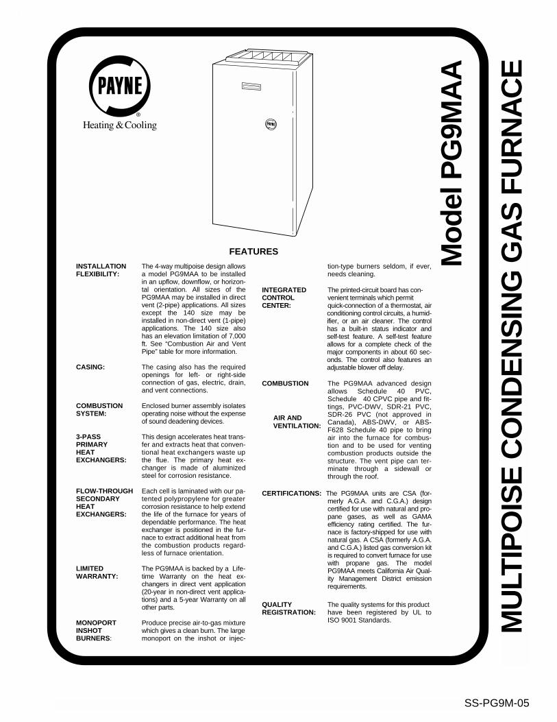
SS-PG9M-05 MULTIPOISE CONDENSING GAS FURNACE Model PG9MAA FEATURES INSTALLATION The 4-way multipoise design allows FLEXIBILITY: a model PG9MAA to be installed in an upflow, downflow, or horizon- tal orientation. All sizes of the PG9MAA may be installed in direct vent (2-pipe) applications. All sizes except the 140 size may be installed in non-direct vent (1-pipe) applications. The 140 size also has an elevation limitation of 7,000 ft. See “Combustion Air and Vent Pipe” table for more information. CASING: The casing also has the required openings for left- or right-side connection of gas, electric, drain, and vent connections. COMBUSTION Enclosed burner assembly isolates SYSTEM: operating noise without the expense of sound deadening devices. 3-PASS This design accelerates heat trans- PRIMARY fer and extracts heat that conven- HEAT tional heat exchangers waste up EXCHANGERS: the flue. The primary heat ex- changer is made of aluminized steel for corrosion resistance. FLOW-THROUGH Each cell is laminated with our pa- SECONDARY tented polypropylene for greater HEAT corrosion resistance to help extend EXCHANGERS: the life of the furnace for years of dependable performance. The heat exchanger is positioned in the fur- nace to extract additional heat from the combustion products regard- less of furnace orientation. LIMITED The PG9MAA is backed by a Life- WARRANTY: time Warranty on the heat ex- changers in direct vent application (20-year in non-direct vent applica- tions) and a 5-year Warranty on all other parts. MONOPORT Produce precise air-to-gas mixture INSHOT which gives a clean burn. The large BURNERS: monoport on the inshot or injec- tion-type burners seldom, if ever, needs cleaning. INTEGRATED The printed-circuit board has con- CONTROL venient terminals which permit CENTER: quick-connection of a thermostat, air conditioning control circuits, a humid- ifier, or an air cleaner. The control has a built-in status indicator and self-test feature. A self-test feature allows for a complete check of the major components in about 60 sec- onds. The control also features an adjustable blower off delay. COMBUSTION The PG9MAA advanced design allows Schedule 40 PVC, Schedule 40 CPVC pipe and fit- tings, PVC-DWV, SDR-21 PVC, SDR-26 PVC (not approved in Canada), ABS-DWV, or ABS- F628 Schedule 40 pipe to bring air into the furnace for combus- tion and to be used for venting combustion products outside the structure. The vent pipe can ter- minate through a sidewall or through the roof. CERTIFICATIONS: The PG9MAA units are CSA (for- merly A.G.A. and C.G.A.) design certified for use with natural and pro- pane gases, as well as GAMA efficiency rating certified. The fur- nace is factory-shipped for use with natural gas. A CSA (formerly A.G.A. and C.G.A.) listed gas conversion kit is required to convert furnace for use with propane gas. The model PG9MAA meets California Air Qual- ity Management District emission requirements. QUALITY The quality systems for this product REGISTRATION: have been registered by UL to ISO 9001 Standards. AIR AND VENTILATION: Time Roman

Welcome message from author
This document is posted to help you gain knowledge. Please leave a comment to let me know what you think about it! Share it to your friends and learn new things together.
Transcript
SS-PG9M-05
MU
LTIP
OIS
E C
ON
DE
NS
ING
GA
S F
UR
NA
CE
Mod
el P
G9M
AA
FEATURES
INSTALLATION
The 4-way multipoise design allows
FLEXIBILITY:
a model PG9MAA to be installedin an upflow, downflow, or horizon-tal orientation. All sizes of thePG9MAA may be installed in directvent (2-pipe) applications. All sizesexcept the 140 size may beinstalled in non-direct vent (1-pipe)applications. The 140 size alsohas an elevation limitation of 7,000ft. See “Combustion Air and VentPipe” table for more information.
CASING:
The casing also has the requiredopenings for left- or right-sideconnection of gas, electric, drain,and vent connections.
COMBUSTION
Enclosed burner assembly isolates
SYSTEM:
operating noise without the expenseof sound deadening devices.
3-PASS
This design accelerates heat trans-
PRIMARY
fer and extracts heat that conven-
HEAT
tional heat exchangers waste up
EXCHANGERS:
the flue. The primary heat ex-changer is made of aluminizedsteel for corrosion resistance.
FLOW-THROUGH
Each cell is laminated with our pa-
SECONDARY
tented polypropylene for greater
HEAT
corrosion resistance to help extend
EXCHANGERS:
the life of the furnace for years ofdependable performance. The heatexchanger is positioned in the fur-nace to extract additional heat fromthe combustion products regard-less of furnace orientation.
LIMITED
The PG9MAA is backed by a Life-
WARRANTY:
time Warranty on the heat ex-changers in direct vent application(20-year in non-direct vent applica-tions) and a 5-year Warranty on allother parts.
MONOPORT
Produce precise air-to-gas mixture
INSHOT
which gives a clean burn. The large
BURNERS
: monoport
on the inshot or injec-
tion
-
type burners seldom, if ever,needs cleaning.
INTEGRATED
The printed-circuit board has con-
CONTROL
venient terminals which permit
CENTER:
quick-connection of a thermostat, airconditioning control circuits, a humid-ifier, or an air cleaner. The controlhas a built-in status indicator andself-test feature. A self-test featureallows for a complete check of themajor components in about 60 sec-onds. The control also features anadjustable blower off delay.
COMBUSTION
The PG9MAA advanced designallows Schedule 40 PVC,Schedule 40 CPVC pipe and fit-tings,
PVC-DWV, SDR-21 PVC,SDR-26 PVC (not approved inCanada), ABS-DWV, or ABS-F628 Schedule 40 pipe to bringair into the furnace for combus-tion and to be used for ventingcombustion products outside thestructure. The vent pipe can ter-minate through a sidewall orthrough the roof.
CERTIFICATIONS:
The PG9MAA units are CSA (for-merly A.G.A. and C.G.A.) designcertified for use with natural and pro-pane gases, as well as GAMAefficiency rating certified. The fur-nace is factory-shipped for use withnatural gas. A CSA (formerly A.G.A.and C.G.A.) listed gas conversion kitis required to convert furnace for usewith propane gas. The modelPG9MAA meets California Air Qual-ity Management District emissionrequirements.
QUALITY
The quality systems for this product
REGISTRATION:
have been registered by UL toISO 9001 Standards.
AIR ANDVENTILATION:
Time
Roman
—2—
11 ⁄4"
1"
13⁄16
"5 ⁄8
" 5 ⁄16"
1"
39 7 ⁄8
"
11⁄16
"
7 ⁄16"
14 1 ⁄2
"T
YP
17 5 ⁄1
6"24 1 ⁄2
"27 9 ⁄1
6"T
YP
27 5 ⁄8
"29 11
⁄16"
TY
P
30 13
⁄16"32
5 ⁄8"
TY
P
33 1 ⁄4
"T
YP
CO
ND
EN
SAT
ED
RA
IN T
RA
PLO
CAT
ION
(ALT
ER
NAT
EU
PF
LOW
)
7 ⁄8-I
N. D
IAA
CC
ES
SO
RY
PO
WE
R E
NT
RY
7 ⁄8-I
N. D
IAP
OW
ER
CO
NN
CO
ND
EN
SAT
E D
RA
INT
RA
P L
OC
ATIO
N(D
OW
NF
LOW
&H
OR
IZO
NTA
L LE
FT
)
26 15
⁄16"
24 1 ⁄2
"
22 5 ⁄1
6"
2-IN
. CO
MB
US
TIO
N-
AIR
CO
NN
1 ⁄2-I
N. D
IAG
AS
CO
NN
2-IN
. VE
NT
CO
NN
1 ⁄2-I
N. D
IA T
HE
RM
OS
TAT
EN
TR
Y22
11⁄16
"
SID
E IN
LET
23 1 ⁄4
" T
YP
SID
E IN
LET
OU
TLE
T
26 15
⁄16"
28 1 ⁄2
"
22 5 ⁄1
6"
19"
22 1 ⁄4
" T
YP
24 3 ⁄1
6"B
OT
TOM
INLE
T
18 1 ⁄4
"
22 11
⁄16"
2-IN
. CO
MB
US
TIO
N-
AIR
CO
NN 1 ⁄2
-IN
. DIA
GA
S C
ON
N
7 ⁄8-I
N. D
IAP
OW
ER
CO
NN
1 ⁄2-I
N. D
IAT
HE
RM
OS
TAT
EN
TR
Y
2-IN
. VE
NT
CO
NN
DIM
PLE
LO
CAT
OR
SF
OR
HO
RIZ
ON
TAL
HA
NG
ING
SID
E IN
LET
9 7 ⁄1
6"T
YP
26 15
⁄16"
TY
P
CO
ND
EN
SAT
ED
RA
IN L
OC
ATIO
N(U
PF
LOW
)
30 1 ⁄2
"
9 ⁄16"
TY
P
CO
ND
EN
SAT
ED
RA
IN L
OC
ATIO
N(U
PF
LOW
)E
INLE
T
11/16
"11
/16"
D13
/16"
13/16
"
OU
TLE
T
A
AIR
FLO
W26
1 ⁄4"
26 1 ⁄4
"
CO
ND
EN
SAT
E D
RA
INT
RA
P L
OC
ATIO
N(D
OW
NF
LOW
&H
OR
IZO
NTA
L R
IGH
T)
OR
ALT
ER
NAT
E1 ⁄2
-IN
. DIA
GA
S C
ON
N
NO
TES
: M
inim
um r
etur
n-ai
r op
enin
g at
furn
ace,
bas
ed o
n m
etal
duc
t. If
flex
duct
is u
sed,
see
flex
duc
t man
ufac
ture
r's r
ecom
men
datio
n fo
r eq
uiva
lent
dia
met
ers:
1. F
or 8
00 C
FM
16
-in. r
ound
or
14-1
/2 X
12-
in. r
ecta
ngle
. 2
. For
120
0 C
FM
20
-in. r
ound
or
14-1
/2 X
19-
1 /2
in. r
ecta
ngle
. 3
. For
160
0 C
FM
22
-in. r
ound
or
14-1
/2 X
23-
1 /4
in. r
ecta
ngle
. 4
. For
airf
low
req
uire
men
ts a
bove
180
0 C
FM
, see
Air
Del
iver
y T
able
in p
rodu
ct S
peci
ficat
ion
She
et fo
r sp
ecifi
c us
e of
sin
gle
side
inle
ts. T
he u
se o
f bot
h si
de in
lets
, a c
ombi
natio
n of
1 s
ide
and
the
botto
m, o
r th
e bo
ttom
onl
y w
ill e
nsur
e ad
equa
te r
etur
n-ai
r o
peni
ngs
for
airf
low
req
uire
men
ts a
bove
180
0 C
FM
at 0
.5” W
.C. E
SP.
A02
185
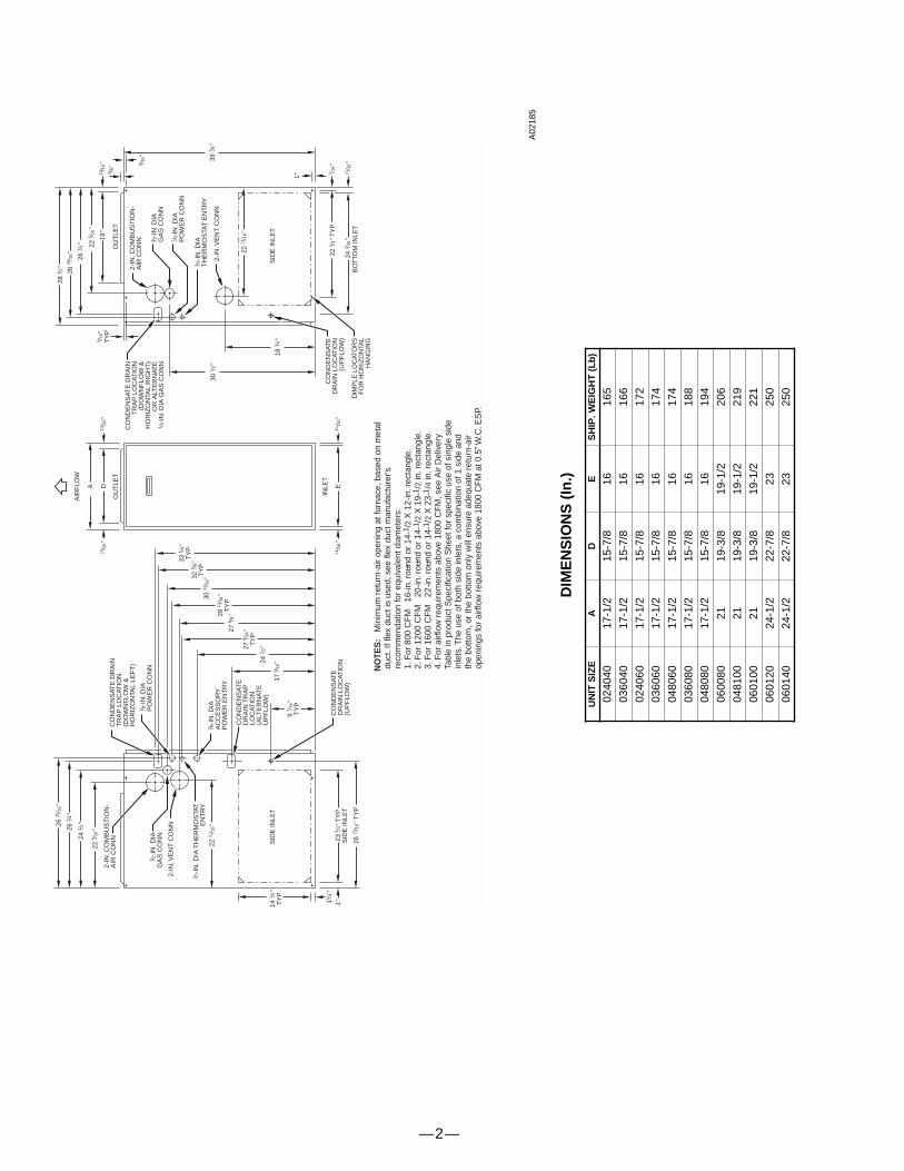
DIM
EN
SIO
NS
(In
.)
UN
IT S
IZE
AD
ES
HIP
. WE
IGH
T (
Lb
)
0240
4017
-1/2
15-7
/816
165
0360
4017
-1/2
15-7
/816
166
0240
6017
-1/2
15-7
/816
172
0360
6017
-1/2
15-7
/816
174
0480
6017
-1/2
15-7
/816
174
0360
8017
-1/2
15-7
/816
188
0480
8017
-1/2
15-7
/816
194
0600
8021
19-3
/819
-1/2
206
0481
0021
19-3
/819
-1/2
219
0601
0021
19-3
/819
-1/2
221
0601
2024
-1/2
22-7
/823
250
0601
4024
-1/2
22-7
/823
250

—3—
1⁄2 ODINDUCER HOUSINGDRAIN CONNECTION
1⁄4 ODCOLLECTOR BOX TOTRAP RELIEF PORT
5⁄8 ODCOLLECTOR BOXDRAIN CONNECTION
1⁄2-IN. PVC OR CPVC
SCREW HOLE FORUPFLOW OR DOWN-FLOW APPLICATIONS(OPTIONAL)
1 42
7 8
1 87
SLOT FOR SCREWHORIZONTALAPPLICATION
(OPTIONAL)
WIRE TIEGUIDES(WHEN USED)
1 21
3 41
3 4
FRONT VIEW SIDE VIEW
FURNACEDOOR
FURNACEDOOR CONDENSATE
TRAP
78
1 426
4
FURNACESIDEFURNACE
SIDE
1 21
1 426
43 45 3 45
4
SIDE VIEW FRONT VIEW END VIEW FRONT VIEW
3 4
DOWNFLOW AND ALTERNATEEXTERNAL UPFLOW APPLICATIONS
HORIZONTALAPPLICATIONS
FIELDDRAINCONN
FIELDDRAINCONN
CONDENSATETRAP (INSIDE)
BLOWER SHELF
ALTERNATE DRAINTUBE LOCATION
UPFLOW APPLICATIONS
CONDENSATE TRAPDRAIN TUBE LOCATION
MEETS DOE RESIDENTIAL CONSERVATION SERVICESPROGRAM STANDARDS.
Before purchasing this appliance, read importantenergy cost and efficiency information availablefrom your retailer.
A93026
CONDENSATE TRAP
ama
D E S I G N
C E R T I F I E D ®
As an ENERGY STAR® partner, Payne Heating & Cooling has determined that this product meets the ENERGY STAR® guidelines for energy efficiency.
REGISTERED
ISO 9001:2000
—4—
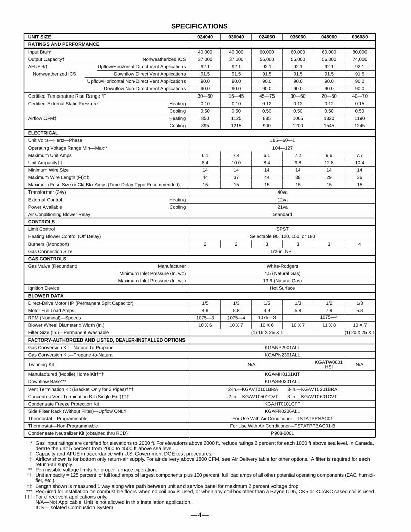
SPECIFICATIONS
* Gas input ratings are certified for elevations to 2000 ft. For elevations above 2000 ft, reduce ratings 2 percent for each 1000 ft above sea level. In Canada, derate the unit 5 percent from 2000 to 4500 ft above sea level.
† Capacity and AFUE in accordance with U.S. Government DOE test procedures.‡ Airflow shown is for bottom only return-air supply. For air delivery above 1800 CFM, see Air Delivery table for other options. A filter is required for each
return-air supply.** Permissible voltage limits for proper furnace operation.
†† Unit ampacity = 125 percent of full load amps of largest components plus 100 percent full load amps of all other potential operating components (EAC, humidi-fier, etc.).
‡‡ Length shown is measured 1 way along wire path between unit and service panel for maximum 2 percent voltage drop.*** Required for installation on combustible floors when no coil box is used, or when any coil box other than a Payne CD5, CK5 or KCAKC cased coil is used.
††† For direct vent applications only.N/A—Not Applicable. Unit is not allowed in this installation application.ICS—Isolated Combustion System
UNIT SIZE 024040 036040 024060 036060 048060 036080
RATINGS AND PERFORMANCE
Input Btuh* 40,000 40,000 60,000 60,000 60,000 80,000
Output Capacity† Nonweatherized ICS 37,000 37,000 56,000 56,000 56,000 74,000
AFUE%† Upflow/Horizontal Direct Vent Applications 92.1 92.1 92.1 92.1 92.1 92.1
Nonweatherized ICS Downflow Direct Vent Applications 91.5 91.5 91.5 91.5 91.5 91.5
Upflow/Horizontal Non-Direct Vent Applications 90.0 90.0 90.0 90.0 90.0 90.0
Downflow Non-Direct Vent Applications 90.0 90.0 90.0 90.0 90.0 90.0
Certified Temperature Rise Range °F 30—60 15—45 45—75 30—60 20—50 40—70
Certified External Static Pressure Heating 0.10 0.10 0.12 0.12 0.12 0.15
Cooling 0.50 0.50 0.50 0.50 0.50 0.50
Airflow CFM‡ Heating 850 1125 885 1065 1320 1190
Cooling 895 1215 900 1200 1545 1245
ELECTRICAL
Unit Volts—Hertz—Phase 115—60—1
Operating Voltage Range Min—Max** 104—127
Maximum Unit Amps 6.1 7.4 6.1 7.2 9.6 7.7
Unit Ampacity†† 8.4 10.0 8.4 9.8 12.8 10.4
Minimum Wire Size 14 14 14 14 14 14
Maximum Wire Length (Ft)‡‡ 44 37 44 38 29 36
Maximum Fuse Size or Ckt Bkr Amps (Time-Delay Type Recommended) 15 15 15 15 15 15
Transformer (24v) 40va
External Control Heating 12va
Power Available Cooling 21va
Air Conditioning Blower Relay Standard
CONTROLS
Limit Control SPST
Heating Blower Control (Off Delay) Selectable 90, 120, 150, or 180
Burners (Monoport) 2 2 3 3 3 4
Gas Connection Size 1/2-in. NPT
GAS CONTROLS
Gas Valve (Redundant) Manufacturer White-Rodgers
Minimum Inlet Pressure (In. wc) 4.5 (Natural Gas)
Maximum Inlet Pressure (In. wc) 13.6 (Natural Gas)
Ignition Device Hot Surface
BLOWER DATA
Direct-Drive Motor HP (Permanent Split Capacitor) 1/5 1/3 1/5 1/3 1/2 1/3
Motor Full Load Amps 4.9 5.8 4.9 5.8 7.9 5.8
RPM (Nominal)—Speeds 1075—3 1075—4 1075—3 1075—4
Blower Wheel Diameter x Width (In.) 10 X 6 10 X 7 10 X 6 10 X 7 11 X 8 10 X 7
Filter Size (In.)—Permanent Washable (1) 16 X 25 X 1 (1) 20 X 25 X 1
FACTORY-AUTHORIZED AND LISTED, DEALER-INSTALLED OPTIONS
Gas Conversion Kit—Natural-to-Propane KGANP2901ALL
Gas Conversion Kit—Propane-to-Natural KGAPN2301ALL
Twinning Kit N/A KGATW0601HSI N/A
Manufactured (Mobile) Home Kit††† KGAMH0101KIT
Downflow Base*** KGASB0201ALL
Vent Termination Kit (Bracket Only for 2 Pipes)††† 2-in.—KGAVT0101BRA 3-in.—KGAVT0201BRA
Concentric Vent Termination Kit (Single Exit)††† 2-in.—KGAVT0501CVT 3-in.—KGAVT0601CVT
Condensate Freeze Protection Kit KGAHT0101CFP
Side Filter Rack (Without Filter)—Upflow ONLY KGAFR0206ALL
Thermostat—Programmable For Use With Air Conditioner—TSTATPPSAC01
Thermostat—Non-Programmable For Use With Air Conditioner—TSTATPPBAC01-B
Condensate Neutralizer Kit (obtained thru RCD) P908-0001
—5—
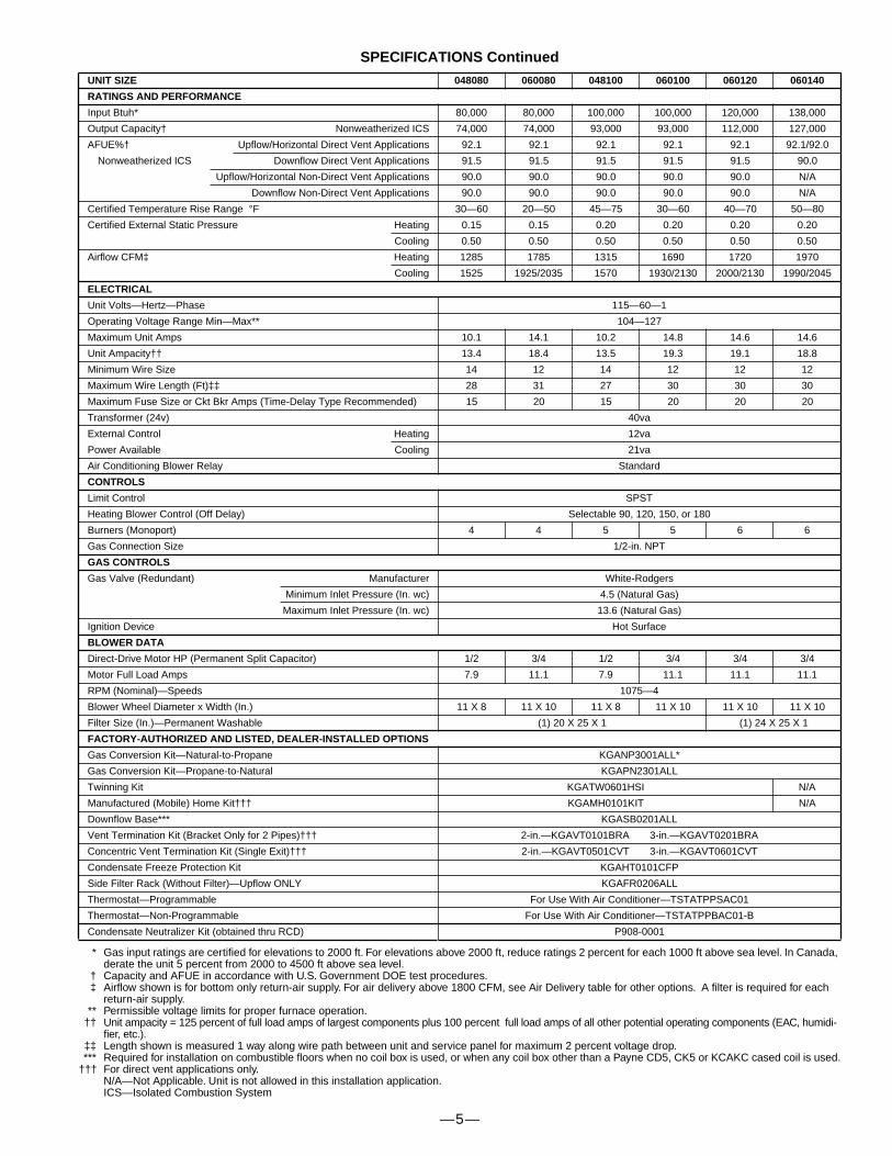
SPECIFICATIONS Continued
* Gas input ratings are certified for elevations to 2000 ft. For elevations above 2000 ft, reduce ratings 2 percent for each 1000 ft above sea level. In Canada, derate the unit 5 percent from 2000 to 4500 ft above sea level.
† Capacity and AFUE in accordance with U.S. Government DOE test procedures.‡ Airflow shown is for bottom only return-air supply. For air delivery above 1800 CFM, see Air Delivery table for other options. A filter is required for each
return-air supply.** Permissible voltage limits for proper furnace operation.
†† Unit ampacity = 125 percent of full load amps of largest components plus 100 percent full load amps of all other potential operating components (EAC, humidi-fier, etc.).
‡‡ Length shown is measured 1 way along wire path between unit and service panel for maximum 2 percent voltage drop.*** Required for installation on combustible floors when no coil box is used, or when any coil box other than a Payne CD5, CK5 or KCAKC cased coil is used.
††† For direct vent applications only.N/A—Not Applicable. Unit is not allowed in this installation application.ICS—Isolated Combustion System
UNIT SIZE 048080 060080 048100 060100 060120 060140
RATINGS AND PERFORMANCE
Input Btuh* 80,000 80,000 100,000 100,000 120,000 138,000
Output Capacity† Nonweatherized ICS 74,000 74,000 93,000 93,000 112,000 127,000
AFUE%† Upflow/Horizontal Direct Vent Applications 92.1 92.1 92.1 92.1 92.1 92.1/92.0
Nonweatherized ICS Downflow Direct Vent Applications 91.5 91.5 91.5 91.5 91.5 90.0
Upflow/Horizontal Non-Direct Vent Applications 90.0 90.0 90.0 90.0 90.0 N/A
Downflow Non-Direct Vent Applications 90.0 90.0 90.0 90.0 90.0 N/A
Certified Temperature Rise Range °F 30—60 20—50 45—75 30—60 40—70 50—80
Certified External Static Pressure Heating 0.15 0.15 0.20 0.20 0.20 0.20
Cooling 0.50 0.50 0.50 0.50 0.50 0.50
Airflow CFM‡ Heating 1285 1785 1315 1690 1720 1970
Cooling 1525 1925/2035 1570 1930/2130 2000/2130 1990/2045
ELECTRICAL
Unit Volts—Hertz—Phase 115—60—1
Operating Voltage Range Min—Max** 104—127
Maximum Unit Amps 10.1 14.1 10.2 14.8 14.6 14.6
Unit Ampacity†† 13.4 18.4 13.5 19.3 19.1 18.8
Minimum Wire Size 14 12 14 12 12 12
Maximum Wire Length (Ft)‡‡ 28 31 27 30 30 30
Maximum Fuse Size or Ckt Bkr Amps (Time-Delay Type Recommended) 15 20 15 20 20 20
Transformer (24v) 40va
External Control Heating 12va
Power Available Cooling 21va
Air Conditioning Blower Relay Standard
CONTROLS
Limit Control SPST
Heating Blower Control (Off Delay) Selectable 90, 120, 150, or 180
Burners (Monoport) 4 4 5 5 6 6
Gas Connection Size 1/2-in. NPT
GAS CONTROLS
Gas Valve (Redundant) Manufacturer White-Rodgers
Minimum Inlet Pressure (In. wc) 4.5 (Natural Gas)
Maximum Inlet Pressure (In. wc) 13.6 (Natural Gas)
Ignition Device Hot Surface
BLOWER DATA
Direct-Drive Motor HP (Permanent Split Capacitor) 1/2 3/4 1/2 3/4 3/4 3/4
Motor Full Load Amps 7.9 11.1 7.9 11.1 11.1 11.1
RPM (Nominal)—Speeds 1075—4
Blower Wheel Diameter x Width (In.) 11 X 8 11 X 10 11 X 8 11 X 10 11 X 10 11 X 10
Filter Size (In.)—Permanent Washable (1) 20 X 25 X 1 (1) 24 X 25 X 1
FACTORY-AUTHORIZED AND LISTED, DEALER-INSTALLED OPTIONS
Gas Conversion Kit—Natural-to-Propane KGANP3001ALL*
Gas Conversion Kit—Propane-to-Natural KGAPN2301ALL
Twinning Kit KGATW0601HSI N/A
Manufactured (Mobile) Home Kit††† KGAMH0101KIT N/A
Downflow Base*** KGASB0201ALL
Vent Termination Kit (Bracket Only for 2 Pipes)††† 2-in.—KGAVT0101BRA 3-in.—KGAVT0201BRA
Concentric Vent Termination Kit (Single Exit)††† 2-in.—KGAVT0501CVT 3-in.—KGAVT0601CVT
Condensate Freeze Protection Kit KGAHT0101CFP
Side Filter Rack (Without Filter)—Upflow ONLY KGAFR0206ALL
Thermostat—Programmable For Use With Air Conditioner—TSTATPPSAC01
Thermostat—Non-Programmable For Use With Air Conditioner—TSTATPPBAC01-B
Condensate Neutralizer Kit (obtained thru RCD) P908-0001

—6—
COMBUSTION-AIR AND VENT PIPING FOR DIRECT VENT (2 PIPE) APPLICATIONS
MAXIMUM ALLOWABLE PIPE LENGTH (FT)
* Disk usage—Unless otherwise specified, use perforated disk assembly (factory-supplied in loose parts bag). If one disk is stated, separate 2 halves of per-forated disk assembly and use shouldered disk half. When using shouldered disk half, install screen side toward inlet box.
† Wide radius elbow.‡ Vent sizing for Canadian installations above 4500 ft (1370m) above sea level are subject to acceptance by the local authorities having jurisdiction.N/A — Not Allowed. Pressure switch will not make.
NOTES:
1. Do not use pipe size greater than those specified in table or incomplete combustion, flame disturbance, or flame sense lockout may occur.2. Size both the combustion-air and vent pipe independently, then use the larger diameter for both pipes.3. Assume two 45° elbows equal one 90° elbow. Long radius elbows are desirable and may be required in some cases.4. Elbows and pipe sections within the furnace casing and at the vent termination should not be included in vent length or elbow count.5. The minimum pipe length is 5 ft for all applications.6. Use 3-in. diameter vent termination kit for installations requiring 4-in. diameter pipe.
ALTITUDE ABOVE SEA LEVEL (FT) UNIT SIZE
TERMINATIONTYPE
PIPEDIAMETER
(IN.)*NUMBER OF 90° ELBOWS
1 2 3 4 5 6
0 to 2000
024040036040 2 Pipe or 2-in. Concentric
1 5 NA NA NA NA NA1-1/2 70 70 65 60 60 55
2 70 70 70 70 70 70024060036060048060
2 Pipe or 2-in. Concentric1-1/2 20 15 10 5 NA NA
2 70 70 70 70 70 70
036080048080060080
2 Pipe or 2-in. Concentric1-1/2 10 NA NA NA NA NA
2 55 50 35 30 30 20 2-1/2 70 70 70 70 70 70
048100060100 2 Pipe or 3-in. Concentric
2 5 NA NA NA NA NA2-1/2 40 30 20 20 10 NA
3 70 70 70 70 70 70
060120 2 Pipe or 3-in. Concentric2-1/2 one disk 10 NA NA NA NA NA
3† 45 40 35 30 25 203† no disk 70 70 70 70 70 70
060140 2 Pipe or 3-in. Concentric
2-1/2 one disk 5 NA NA NA NA NA3† one disk 40 35 30 25 20 153† no disk 60 56 52 48 44 404† no disk 70 70 70 70 70 70
2001 to 3000
024040036040 2 Pipe or 2-in. Concentric
1-1/2 67 62 57 52 52 472 70 70 70 70 70 70
024060036060048060
2 Pipe or 2-in. Concentric1-1/2 17 12 7 NA NA NA
2 70 67 66 61 61 61036080048080060080
2 Pipe or 2-in. Concentric2 49 44 30 25 25 15
2-1/2 70 70 70 70 70 70
048100060100 2 Pipe or 3-in. Concentric
2-1/2 35 26 16 16 6 NA3 70 70 70 70 66 61
060120 2 Pipe or 3-in. Concentric3 14 9 NA NA NA NA
3† no disk 70 70 63 56 50 434† no disk 70 70 70 70 70 70
060140 2 Pipe or 3-in. Concentric3† one disk 20 15 10 5 NA NA3† no disk 39 35 31 27 23 194† no disk 70 70 70 70 70 70
3001 to 4000
024040036040 2 Pipe or 2-in. Concentric
1-1/2 64 59 54 49 48 432 70 70 70 70 70 70
024060036060048060
2 Pipe or 2-in. Concentric1-1/2 16 11 6 NA NA NA
2 68 63 62 57 57 56036080048080060080
2 Pipe or 2-in. Concentric2 46 41 28 23 22 13
2-/12 70 70 70 70 70 70
048100060100 2 Pipe or 3-in. Concentric
2-1/2 33 24 15 14 5 NA 3 70 70 70 66 61 56
060120 2 Pipe or 3-in. Concentric3† no disk 65 58 51 44 38 314† no disk 70 70 70 70 70 70
060140 2 Pipe or 3-in. Concentric3† one disk 11 6 NA NA NA NA3† no disk 30 26 22 18 14 104† no disk 70 70 70 70 70 70

—7—
MAXIMUM ALLOWABLE PIPE LENGTH (FT) Continued
* Disk usage—Unless otherwise specified, use perforated disk assembly (factory-supplied in loose parts bag). If one disk is stated, separate 2 halves of per-forated disk assembly and use shouldered disk half. When using shouldered disk half, install screen side toward inlet box.
† Wide radius elbow.‡ Vent sizing for Canadian installations above 4500 ft (1370m) above sea level are subject to acceptance by the local authorities having jurisdiction.N/A — Not Allowed. Pressure switch will not make.
NOTES:
1. Do not use pipe size greater than those specified in table or incomplete combustion, flame disturbance, or flame sense lockout may occur.2. Size both the combustion-air and vent pipe independently, then use the larger diameter for both pipes.3. Assume two 45° elbows equal one 90° elbow. Long radius elbows are desirable and may be required in some cases.4. Elbows and pipe sections within the furnace casing and at the vent termination should not be included in vent length or elbow count.5. The minimum pipe length is 5 ft for all applications.6. Use 3-in. diameter vent termination kit for installations requiring 4-in. diameter pipe.
ALTITUDE ABOVE SEA LEVEL (FT) UNIT SIZE
TERMINATIONTYPE
PIPEDIAMETER
(IN.)*NUMBER OF 90° ELBOWS
1 2 3 4 5 6
4001 to 5000‡
024040036040 2 Pipe or 2-in. Concentric
1-1/2 60 55 50 45 44 39 2 70 70 70 70 70 70
024060036060048060
2 Pipe or 2-in. Concentric1-1/2 15 10 5 NA NA NA
2 64 59 58 53 52 52036080048080060080
2 Pipe or 2-in. Concentric2 44 39 26 21 20 11
2-1/2 70 70 70 70 70 70
048100060100 2 Pipe or 3-in. Concentric
2-1/2 31 22 13 12 NA NA 3 70 70 67 62 57 52
060120 2 Pipe or 3-in. Concentric3† no disk 53 46 40 33 26 204† no disk 70 70 70 70 70 70
060140 2 Pipe or 3-in. Concentric3† no disk 21 17 13 9 5 NA4† no disk 69 64 59 54 49 44
5001 to 6000‡
024040036040 2 Pipe or 2-In. Concentric
1-1/2 57 52 47 42 40 352 70 70 70 70 70 70
024060036060048060
2 Pipe or 2-In. Concentric1-1/2 14 9 NA NA NA NA
2 60 55 54 49 48 47036080048080060080
2 Pipe or 2-In. Concentric2 41 36 23 18 17 8
2-1/2 70 70 70 70 70 70
048100060100 2 Pipe or 3-In. Concentric
2-1/2 29 21 12 11 NA NA3 70 67 62 57 52 47
060120 2 Pipe or 3-In. Concentric3† no disk 42 35 29 22 15 94† no disk 70 70 70 70 70 70
060140 2 Pipe or 3-In. Concentric3† no disk 12 8 NA NA NA NA4† no disk 42 37 32 27 22 17
6001 to 7000‡
024040036040 2 Pipe or 2-In. Concentric
1-1/2 53 48 43 38 37 322 70 70 68 67 66 64
024060036060048060
2 Pipe or 2-In. Concentric1-1/2 13 8 NA NA NA NA
2 57 52 50 45 44 43036080048080060080
2 Pipe or 2-In. Concentric2 38 33 21 16 15 6
2-1/2 70 70 68 67 66 64
048100060100 2 Pipe or 3-In. Concentric
2-1/2 27 19 10 9 NA NA3 68 63 58 53 48 43
060120 2 Pipe or 3-In. Concentric3† no disk 31 24 18 11 NA NA4† no disk 70 70 70 70 70 70
060140 2 Pipe or 3-In. Concentric 4† no disk 17 12 7 NA NA NA
7001 to 8000‡
024040036040 2 Pipe or 2-In. Concentric
1-1/2 49 44 39 34 33 282 66 65 63 62 60 59
024060036060048060
2 Pipe or 2-In. Concentric1-1/2 12 7 NA NA NA NA
2 53 48 46 41 40 38036080048080060080
2 Pipe or 2-In. Concentric2 36 31 19 14 12 NA
2-1/2 66 65 63 62 60 59
048100060100 2 Pipe or 3-In. Concentric
2-1/2 25 17 8 7 NA NA 3 63 58 53 48 43 38
060120 2 Pipe or 3-In. Concentric3† no disk 20 13 7 NA NA NA4† no disk 61 56 51 46 41 36
060140 NA

—8—
MAXIMUM ALLOWABLE PIPE LENGTH (FT) Continued
* Disk usage—Unless otherwise specified, use perforated disk assembly (factory-supplied in loose parts bag). If one disk is stated, separate 2 halves of per-forated disk assembly and use shouldered disk half. When using shouldered disk half, install screen side toward inlet box.
† Wide radius elbow.‡ Vent sizing for Canadian installations above 4500 ft (1370m) above sea level are subject to acceptance by the local authorities having jurisdiction.N/A — Not Allowed. Pressure switch will not make.
NOTES:
1. Do not use pipe size greater than those specified in table or incomplete combustion, flame disturbance, or flame sense lockout may occur.2. Size both the combustion-air and vent pipe independently, then use the larger diameter for both pipes.3. Assume two 45° elbows equal one 90° elbow. Long radius elbows are desirable and may be required in some cases.4. Elbows and pipe sections within the furnace casing and at the vent termination should not be included in vent length or elbow count.5. The minimum pipe length is 5 ft for all applications.6. Use 3-in. diameter vent termination kit for installations requiring 4-in. diameter pipe.
ALTITUDE ABOVE SEA LEVEL (FT) UNIT SIZE
TERMINATIONTYPE
PIPEDIAMETER
(IN.)*NUMBER OF 90° ELBOWS
1 2 3 4 5 6
8001 to 9000‡
024040036040 2 Pipe or 2-In. Concentric
1-1/2 46 41 36 31 29 24 2 62 60 58 56 55 53
024060036060048060
2 Pipe or 2-In. Concentric1-1/2 11 6 NA NA NA NA
2 49 44 42 37 35 34036080048080060080
2 Pipe or 2-In. Concentric2 33 28 17 12 10 NA
2-1/2 62 60 58 56 55 53
048100060100 2 Pipe or 3-In. Concentric
2-1/2 23 15 7 5 NA NA 3 59 54 49 44 39 34
060120 2 Pipe or 3-In. Concentric3† no disk 10 NA NA NA NA NA4† no disk 35 30 25 20 15 10
060140 NA
9001 to10,000‡
024040036040 2 Pipe or 2-In. Concentric
1-1/2 42 37 32 27 25 202 57 55 53 51 49 47
024060036060048060
2 Pipe or 2-In. Concentric 2 45 40 38 33 31 29
036080048080060080
2 Pipe or 2-In. Concentric2 30 25 14 9 7 NA
2-1/2 57 55 53 51 49 47
048100060100 2 Pipe or 3-In. Concentric
2-1/2 21 13 5 NA NA NA 3 54 49 44 39 34 29
060120 2 Pipe or 3-In. Concentric 4† no disk 10 5 NA NA NA NA060140 NA
—9—
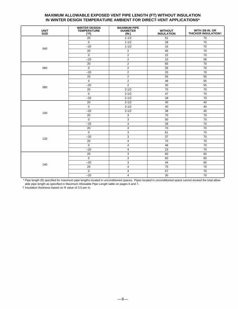
MAXIMUM ALLOWABLE EXPOSED VENT PIPE LENGTH (FT) WITHOUT INSULATIONIN WINTER DESIGN TEMPERATURE AMBIENT FOR DIRECT-VENT APPLICATIONS*
* Pipe length (ft) specified for maximum pipe lengths located in unconditioned spaces. Pipes located in unconditioned space cannot exceed the total allow-able pipe length as specified in Maximum Allowable Pipe Length table on pages 6 and 7.
† Insulation thickness based on R value of 3.5 per in.
UNITSIZE
WINTER DESIGNTEMPERATURE
(°F)
MAXIMUM PIPEDIAMETER
(IN.)WITHOUT
INSULATIONWITH 3/8-IN. OR
THICKER INSULATION†
040
20 1-1/2 51 70
0 1-1/2 28 70
–20 1-1/2 16 70
20 2 45 70
0 2 22 70
–20 2 10 58
06020 2 65 70
0 2 35 70
–20 2 20 70
080
20 2 55 55
0 2 48 55
–20 2 30 55
20 2-1/2 70 70
0 2-1/2 47 70
–20 2-1/2 28 70
100
20 2-1/2 40 40
0 2-1/2 40 40
–20 2-1/2 38 40
20 3 70 70
0 3 50 70
–20 3 28 70
120
20 3 70 70
0 3 61 70
–20 3 37 70
20 4 70 70
0 4 48 70
–20 4 23 70
140
20 3 60 60
0 3 60 60
–20 3 44 60
20 4 70 70
0 4 57 70
–20 4 30 70
—10—
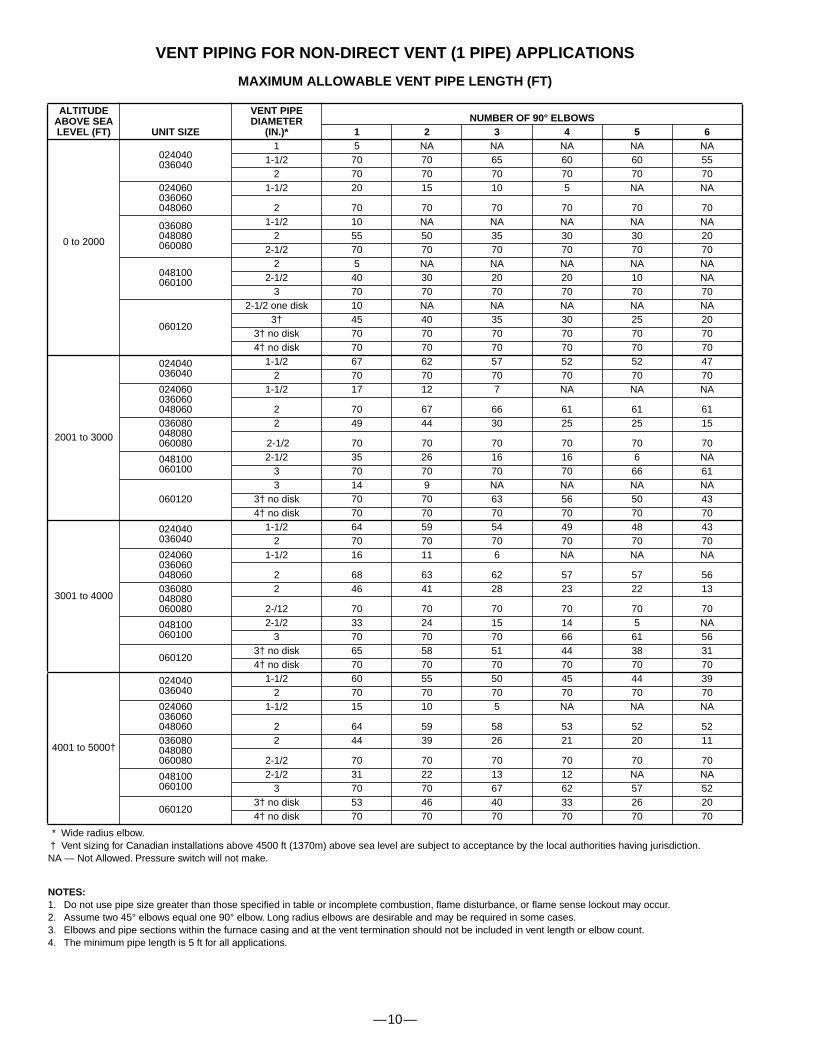
VENT PIPING FOR NON-DIRECT VENT (1 PIPE) APPLICATIONS
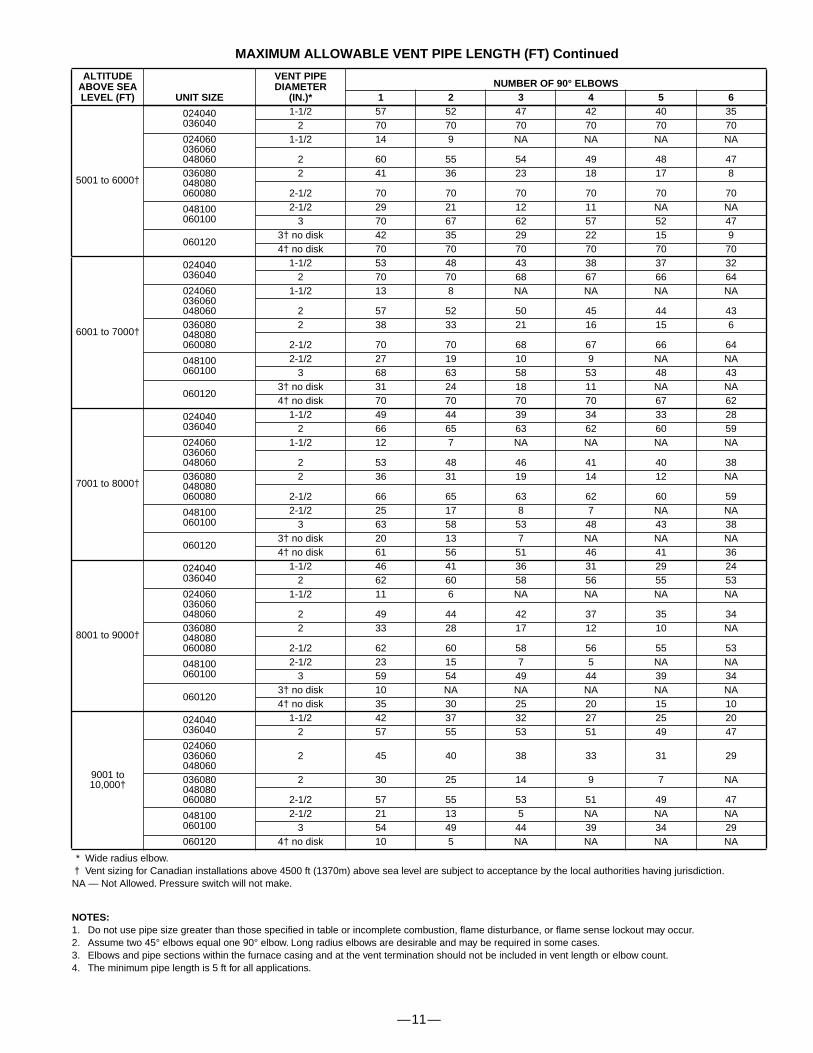
MAXIMUM ALLOWABLE VENT PIPE LENGTH (FT)
* Wide radius elbow.† Vent sizing for Canadian installations above 4500 ft (1370m) above sea level are subject to acceptance by the local authorities having jurisdiction.NA — Not Allowed. Pressure switch will not make.
NOTES:
1. Do not use pipe size greater than those specified in table or incomplete combustion, flame disturbance, or flame sense lockout may occur.2. Assume two 45° elbows equal one 90° elbow. Long radius elbows are desirable and may be required in some cases.3. Elbows and pipe sections within the furnace casing and at the vent termination should not be included in vent length or elbow count.4. The minimum pipe length is 5 ft for all applications.
ALTITUDE ABOVE SEA LEVEL (FT) UNIT SIZE
VENT PIPEDIAMETER
(IN.)*NUMBER OF 90° ELBOWS
1 2 3 4 5 6
0 to 2000
024040036040
1 5 NA NA NA NA NA1-1/2 70 70 65 60 60 55
2 70 70 70 70 70 70024060036060048060
1-1/2 20 15 10 5 NA NA
2 70 70 70 70 70 70
036080048080060080
1-1/2 10 NA NA NA NA NA 2 55 50 35 30 30 20
2-1/2 70 70 70 70 70 70
048100060100
2 5 NA NA NA NA NA2-1/2 40 30 20 20 10 NA
3 70 70 70 70 70 70
060120
2-1/2 one disk 10 NA NA NA NA NA3† 45 40 35 30 25 20
3† no disk 70 70 70 70 70 704† no disk 70 70 70 70 70 70
2001 to 3000
024040036040
1-1/2 67 62 57 52 52 472 70 70 70 70 70 70
024060036060048060
1-1/2 17 12 7 NA NA NA
2 70 67 66 61 61 61036080048080060080
2 49 44 30 25 25 15
2-1/2 70 70 70 70 70 70
048100060100
2-1/2 35 26 16 16 6 NA3 70 70 70 70 66 61
0601203 14 9 NA NA NA NA
3† no disk 70 70 63 56 50 434† no disk 70 70 70 70 70 70
3001 to 4000
024040036040
1-1/2 64 59 54 49 48 432 70 70 70 70 70 70
024060036060048060
1-1/2 16 11 6 NA NA NA
2 68 63 62 57 57 56036080048080060080
2 46 41 28 23 22 13
2-/12 70 70 70 70 70 70
048100060100
2-1/2 33 24 15 14 5 NA 3 70 70 70 66 61 56
0601203† no disk 65 58 51 44 38 314† no disk 70 70 70 70 70 70
4001 to 5000†
024040036040
1-1/2 60 55 50 45 44 39 2 70 70 70 70 70 70
024060036060048060
1-1/2 15 10 5 NA NA NA
2 64 59 58 53 52 52036080048080060080
2 44 39 26 21 20 11
2-1/2 70 70 70 70 70 70
048100060100
2-1/2 31 22 13 12 NA NA 3 70 70 67 62 57 52
0601203† no disk 53 46 40 33 26 204† no disk 70 70 70 70 70 70
—11—
MAXIMUM ALLOWABLE VENT PIPE LENGTH (FT) Continued
* Wide radius elbow.† Vent sizing for Canadian installations above 4500 ft (1370m) above sea level are subject to acceptance by the local authorities having jurisdiction.NA — Not Allowed. Pressure switch will not make.
NOTES:
1. Do not use pipe size greater than those specified in table or incomplete combustion, flame disturbance, or flame sense lockout may occur.2. Assume two 45° elbows equal one 90° elbow. Long radius elbows are desirable and may be required in some cases.3. Elbows and pipe sections within the furnace casing and at the vent termination should not be included in vent length or elbow count.4. The minimum pipe length is 5 ft for all applications.
ALTITUDE ABOVE SEA LEVEL (FT) UNIT SIZE
VENT PIPEDIAMETER
(IN.)*NUMBER OF 90° ELBOWS
1 2 3 4 5 6
5001 to 6000†
024040036040
1-1/2 57 52 47 42 40 352 70 70 70 70 70 70
024060036060048060
1-1/2 14 9 NA NA NA NA
2 60 55 54 49 48 47036080048080060080
2 41 36 23 18 17 8
2-1/2 70 70 70 70 70 70
048100060100
2-1/2 29 21 12 11 NA NA3 70 67 62 57 52 47
0601203† no disk 42 35 29 22 15 94† no disk 70 70 70 70 70 70
6001 to 7000†
024040036040
1-1/2 53 48 43 38 37 322 70 70 68 67 66 64
024060036060048060
1-1/2 13 8 NA NA NA NA
2 57 52 50 45 44 43036080048080060080
2 38 33 21 16 15 6
2-1/2 70 70 68 67 66 64
048100060100
2-1/2 27 19 10 9 NA NA3 68 63 58 53 48 43
0601203† no disk 31 24 18 11 NA NA4† no disk 70 70 70 70 67 62
7001 to 8000†
024040036040
1-1/2 49 44 39 34 33 282 66 65 63 62 60 59
024060036060048060
1-1/2 12 7 NA NA NA NA
2 53 48 46 41 40 38036080048080060080
2 36 31 19 14 12 NA
2-1/2 66 65 63 62 60 59
048100060100
2-1/2 25 17 8 7 NA NA 3 63 58 53 48 43 38
0601203† no disk 20 13 7 NA NA NA4† no disk 61 56 51 46 41 36
8001 to 9000†
024040036040
1-1/2 46 41 36 31 29 24 2 62 60 58 56 55 53
024060036060048060
1-1/2 11 6 NA NA NA NA
2 49 44 42 37 35 34036080048080060080
2 33 28 17 12 10 NA
2-1/2 62 60 58 56 55 53
048100060100
2-1/2 23 15 7 5 NA NA 3 59 54 49 44 39 34
0601203† no disk 10 NA NA NA NA NA4† no disk 35 30 25 20 15 10
9001 to10,000†
024040036040
1-1/2 42 37 32 27 25 202 57 55 53 51 49 47
024060036060048060
2 45 40 38 33 31 29
036080048080060080
2 30 25 14 9 7 NA
2-1/2 57 55 53 51 49 47
048100060100
2-1/2 21 13 5 NA NA NA 3 54 49 44 39 34 29
060120 4† no disk 10 5 NA NA NA NA
—12—
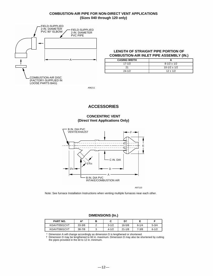
COMBUSTION-AIR PIPE FOR NON-DIRECT VENT APPLICATIONS(Sizes 040 through 120 only)
FIELD-SUPPLIED2-IN. DIAMETERPVC PIPE
FIELD-SUPPLIED2-IN. DIAMETERPVC 90° ELBOW
COMBUSTION-AIR DISC(FACTORY-SUPPLIED INLOOSE PARTS BAG)
A
A96211
LENGTH OF STRAIGHT PIPE PORTION OFCOMBUSTION-AIR INLET PIPE ASSEMBLY (IN.)
CASING WIDTH A
17-1/2 8-1/2 ± 1/221 10-1/2 ± 1/2
24-1/2 12 ± 1/2
ACCESSORIES
CONCENTRIC VENT(Direct Vent Applications Only)
A97110
DIMENSIONS (In.)
* Dimension A will change accordingly as dimension D is lengthened or shortened.† Dimension D may be lengthened to 60 in. maximum. Dimension D may also be shortened by cutting
the pipes provided in the kit to 12 in. minimum.
PART NO. A* B C D† E F
KGAVT0501CVT 33-3/8 2 3-1/2 16-5/8 6-1/4 5-3/4
KGAVT0601CVT 38-7/8 3 4-1/2 21-1/8 7-3/8 6-1/2
C IN. DIA
B IN. DIA PVCVENT/EXHAUST
13/16
B IN. DIA PVCINTAKE/COMBUSTION AIR
D
E
F
A
11/2
Note: See furnace Installation Instructions when venting multiple furnaces near each other.

—13—
17 1⁄8″14 1⁄2″
OPENING
16 1⁄8″23 1⁄8″OPENING
1 1⁄4″
2 3⁄8″
3⁄4″
1⁄2″
25 1⁄8″
1 1⁄4″ (TYP)
3⁄8″TABS
LOCATINGTAB
LOCATINGTAB
1 2 3 4
4 3 2 1
B
D
ACCESSORIES
(Continued)
ACCESSORY DOWNFLOW SUBBASE
A88207
Disassembled
A97427
Assembled
* The plenum should be constructed 1/4-in. smaller in width and depth than the plenum dimensions shown above.
FURNACECASINGWIDTH
PLENUM OPENING* FLOOR OPENING HOLE NO.FOR WIDTH
ADJUSTMENTFURNACE IN DOWNFLOW APPLICATION A B C D
17-1/2Furnace with or without CD5, CK5 Coil
Assembly or KCAKC Coil Box 15-1/8 19 16-3/4 20-3/8 3
21Furnace with or without CD5, CK5 Coil
Assembly or KCAKC Coil Box 18-5/8 19 20-1/4 20-3/8 2
24-1/2Furnace with or without CD5, CK5 Coil
Assembly or KCAKC Coil Box 22-1/8 19 23-3/4 20-3/8 1
��������
C
A
1 1/4″ TYP
PLENUMOPENING
FACTORY-SUPPLIEDFIELD-INSTALLED
INSULATION
SIDE FILTER RACK*
A80199
*Accepts one 16 x 25 x 1 in. filter.

—14—
CLEARANCE TO COMBUSTIBLES
—15—
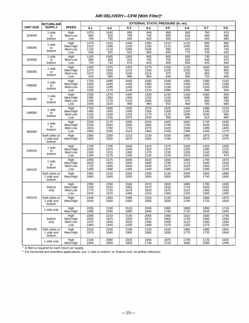
AIR DELIVERY—CFM (With Filter)*
* A filter is required for each return-air supply.* For horizontal and downflow applications, use “1 side or bottom” or “bottom only” as airflow reference.
UNIT SIZERETURN-AIR
SUPPLY SPEEDEXTERNAL STATIC PRESSURE (In. wc)
0.1 0.2 0.3 0.4 0.5 0.6 0.7 0.8
0240401 side
orbottom
HighMed-Low
Low
1075850740
1040825700
995780650
945740620
895685565
840635515
760560455
670480385
0360401 side
orbottom
HighMed-HighMed-Low
Low
147013151125930
141512801110925
140012351085910
128511801045850
12151115990830
11201035915770
995930830705
890825740635
0240601 side
orbottom
HighMed-Low
Low
1100890745
1065865710
1005810670
945765625
900705565
805620505
730540425
610475360
0360601 side
orbottom
HighMed-HighMed-Low
Low
143012701070915
137512601055895
132512151045885
127511601015865
12001105975840
11351035920800
1040950850720
935850750650
0480601 side
orbottom
HighMed-HighMed-Low
Low
1700150013251205
1695146512951170
1640143512651145
1580138512301110
1545135511901080
1450130011501035
138012501105990
131011851050950
0360801 side
orbottom
HighMed-HighMed-Low
Low
1535139512001040
1470135011751020
140513001125990
133012251065960
124511551030910
11601080970860
1065985890785
935880780680
0480801 side
orbottom
HighMed-HighMed-Low
Low
1750149513101135
1685145512601105
1635140512251075
1575135511701040
152513051125995
144512501095995
138011851040910
13101120980860
060080
1 sideor
bottom
HighMed-HighMed-Low
Low
2200210018151560
2175202517601555
2085194517201515
2025186516701460
1925178516201435
1820170015501390
1735162014801340
1635154014051270
both sides or1 side and
bottom
HighMed-High
23601965
22801925
22101870
21301830
20351760
19601710
18751670
17901575
0481001 side
orbottom
HighMed-HighMed-Low
Low
1740150013401195
1705147013151175
1660144513001165
1615141012701130
1570137512351100
1500133012001070
1425128011401030
135512101095975
060100
1 sideor
bottom
HighMed-HighMed-Low
Low
2250202017251490
2175195016901480
2090190016601460
2020184016301440
1930179015751380
1855171015201340
1760164014601295
1670154513701230
both sides or1 side and
bottom
HighMed-High
23601960
23151940
22651930
22001900
21301850
20551800
19651740
18901660
060120
bottomonly
HighMed-HighMed-Low
Low
2350210017701545
2250201517201520
2160195516751465
2070187516201415
2000181015751365
1885171015151325
1790165014501265
1635154013651185
both sides or1 side and
bottom
HighMed-High
24352040
23602000
22851950
22201905
21301835
20501790
19651725
18751650
1 side only HighMed-High
22551985
21901930
21151890
20451840
19651780
18901720
18001645
17101560
060140
bottomonly
HighMed-HighMed-Low
Low
2285202016751460
2210197016501445
2140192016201430
2065187015901400
1990180515601370
1910173015101320
1830166014501275
1745159013901230
both sides or1 side and
bottom
HighMed-High
23101975
22551945
21851900
21201860
20451835
19651775
18801720
18001640
1 side only HighMed-High
21401930
20801850
20251800
19451740
18751725
17951660
17251580
16251495

SPECIFICATIONS SUBJECT TO CHANGE WITHOUT NOTICE
UNIT MUST BE INSTALLED IN ACCORDANCEWITH INSTALLATION INSTRUCTIONS
Cancels: SS-PG9M-04
© 2004 Payne Heating & Cooling 7310 West Morris Street, Indianapolis, IN 46231 PRINTED IN U.S.A. Catalog No. 52PG-9M5 9-04
—16—
Related Documents