JOURNAL OF ENGINEERING AND APPLIED SCIENCE, VOL. 67, NO. 6, DEC. 2020, PP. 1343-1361 FACULTY OF ENGINEERING, CAIRO UNIVERSITY TIME PERIOD CALCULATIONS FOR TALL BUILDINGS ON PILED-RAFTS INCLUDING SOIL-STRUCTURE INTERACTION EFFECTS A. F. FARID 1 , M. M. EL GALAD 2 AND Y. F. RASHED 3 ABSTRACT The purpose of this paper is to compute time period for tall buildings rested on piled- rafts including soil-structure interaction effects. The pile-pile, pile-soil and soil-soil interactions are considered through the development of two-iteration based coupling procedures between the super and sub-structures. The super-structure is modeled using any commercial finite element software, whereas the sub-structure including the building foundation is modeled using a developed boundary element software (PLPAK). It was demonstrated that the consideration of soil-structure interaction greatly increases the time period and consequently reduces the seismic design forces. KEYWORDS: Time period, Piled-raft foundation, Soil-structure interactions, Tall buildings. 1. INTRODUCTION In different building codes, the calculation of the base shear due to lateral loads is dependent on the time period of the considered building, as well as soil, ductility, building importance factors, etc. Building codes proposed different approximate formulae to calculate the building time period. It has to be noted that the computed values are only dependent on the building height, neglecting the building dimensions and stiffness as well as the effect of the soil flexibility. Equations (1, 2) represent a calculated time period (T) for a building of height (h) according to the ASCE 7-10 (12.8-7) [1] and Euro code EC8 1 Lecturer, Department of Structural Engineering, Cairo University, Giza, Egypt, [email protected] 2 Ph.D. Candidate, Department of Structural Engineering, Cairo University, Giza, Egypt. 3 Professor, Department of Structural Engineering, Cairo University, Giza, Egypt.

Welcome message from author
This document is posted to help you gain knowledge. Please leave a comment to let me know what you think about it! Share it to your friends and learn new things together.
Transcript
JOURNAL OF ENGINEERING AND APPLIED SCIENCE, VOL. 67, NO. 6, DEC. 2020, PP. 1343-1361
FACULTY OF ENGINEERING, CAIRO UNIVERSITY
TIME PERIOD CALCULATIONS FOR TALL BUILDINGS ON PILED-RAFTS
INCLUDING SOIL-STRUCTURE INTERACTION EFFECTS
A. F. FARID1, M. M. EL GALAD2 AND Y. F. RASHED3
ABSTRACT
The purpose of this paper is to compute time period for tall buildings rested on piled-
rafts including soil-structure interaction effects. The pile-pile, pile-soil and soil-soil
interactions are considered through the development of two-iteration based coupling
procedures between the super and sub-structures. The super-structure is modeled using any
commercial finite element software, whereas the sub-structure including the building
foundation is modeled using a developed boundary element software (PLPAK). It was
demonstrated that the consideration of soil-structure interaction greatly increases the time
period and consequently reduces the seismic design forces.
KEYWORDS: Time period, Piled-raft foundation, Soil-structure interactions, Tall
buildings.
1. INTRODUCTION
In different building codes, the calculation of the base shear due to lateral loads is
dependent on the time period of the considered building, as well as soil, ductility, building
importance factors, etc. Building codes proposed different approximate formulae to
calculate the building time period. It has to be noted that the computed values are only
dependent on the building height, neglecting the building dimensions and stiffness as well
as the effect of the soil flexibility. Equations (1, 2) represent a calculated time period (T)
for a building of height (h) according to the ASCE 7-10 (12.8-7) [1] and Euro code EC8
1 Lecturer, Department of Structural Engineering, Cairo University, Giza, Egypt, [email protected] 2 Ph.D. Candidate, Department of Structural Engineering, Cairo University, Giza, Egypt. 3 Professor, Department of Structural Engineering, Cairo University, Giza, Egypt.

A. F. FARID ET AL
1344
[2] respectively. It is to be noted that the Egyptian Code of Practice (ECP 201-2012) [3]
also uses Eq. (2).
𝑇 = 𝐶𝑡 × ℎ𝑥 (1)
𝑇 = 𝐶𝑡 × ℎ3
4⁄ (2)
Where Ct and 𝑥 are parameters dependent on the type of seismic resistance of the
building whether it is a steel or a concrete building.
The first category of researchers tried to modify the empirical formula (1, 2). Others
tried to introduce new empirical formulae (the second researchers’ category). The first
category such as the work of Kwon and Kim [4] tried to modify the empirical formula in
Eq. (1) by analyzing over 191 buildings of different types of resisting systems and recorded
over 67 earthquakes within the time period 1970 till 2008. They measured the time period
of these buildings and compared it to values obtained based on Eq. (1). They recommended
changing the factor Ct to be a lower value for buildings with multiple resisting systems [4].
Dunkerley proposed alternative formula given by Eq. (3) for a multi-story building of (n)
floors each as (m) mass rested on fixed base, as follows [5]
1
𝜔12 = ∑
1
𝑘𝑗∑ 𝑚𝑖
𝑛𝑖=𝑗
𝑛𝑗=1 (3)
Where 𝜔1 represents the lower bound of the natural frequency of the building and
kj is the lateral stiffness of floor number j. Luco [6] modified Dunkerley’s formula [5] as
given by Eq. (4) to take into account the translational, rotational and coupling effect of
rigid foundation on a flexible soil as follows
1
𝜔1𝑇2 =
1
𝜔12 +
1
𝜔𝑓12 +
1
𝜔𝑓22 (4)
Where 𝜔1𝑇 is the total natural frequency, whereas 𝜔𝑓1 and 𝜔𝑓2 are the natural
frequencies of the translation and rotation stiffness including the effect of soil-structure
interaction. In order to determine the value of 𝜔1𝑇 in Eq. (4) an iterative process is
performed as the values of 𝜔𝑓1 and 𝜔𝑓2 are dependent on the foundation stiffness.
Xiong et al. performed experimental tests on steel frames including the effect of one
soil type and compared the measured time period to results obtained from finite element
TIME PERIOD CALCULATIONS FOR TALL BUILDINGS ON PILED-RAFTS ….
1345
analysis using the commercial package (SAP2000) to validate Luco formula [6] given by
Eq. (4) experimentally [7].
The second researchers’ category on the other hand, such as the work of
Hatzigeorgiou and Kanapitsas, introduced a new empirical formula given by Eq. (5) to
calculate the building time period [8] as follows
𝑇 =ℎ𝐶1𝑊𝐶2(𝐶3+𝐶4𝐹)
[1−𝑒𝐶5𝑘𝑠𝐶6
]√(1−𝐶7𝜌) (5)
Where C1, C2, C3, C4, C5, C6, C7 are constants and are equal to 0.745, 0.024, 0.073,
-0.021, -0.706, 0.20, 0.043 respectively, h is the building height, m, W is the width of the
building along considered direction, m, F is equal to 0 in case of using frames and equals
1 in case of infill walls. Ks is the soil stiffness in MN/m3, ρ is the ratio between the shear
walls area along the seismic direction to the total areas of the shear walls. Equation (5) was
based on 3D finite element modelling for 20 real buildings taking into consideration the
effect of soil, which was represented as Winkler springs. The number of floors for these
buildings ranges from three to ten floors (low to mid-rise buildings).
Currently, designers use numerical software programs to calculate the time period
for buildings using one of the following approaches: The first approach is to model the
super-structure on fixed supports ignoring the soil-structure interaction effects [9]. The
disadvantage of this approach is that the computed time period is very small. Hence, such
an approach overestimates the computed seismic forces.
The second approach is to model the super-structure together with the foundation
that typically is modeled resting on Winkler springs to represent soil and piles. This
approach was introduced by Horvath in 1983 [10] till the work of Colasanti and Horvath
in 2010 [11]. Despite this methodology being fast, it is not accurate as the stiffness values
of the soil springs is dependent mainly on the first soil layer. Besides the effect of soil –
soil, soil – pile and pile – pile interactions are neglected. Generally, the computed time
period based on this approach is a bit lower than the actual one. This will also lead to
overestimating the seismic design loads.
The third approach is to model the soil underneath the super and sub-structure as a
three dimensional continuum model. The super-structure is modeled as shell and skeletal

A. F. FARID ET AL
1346
elements; whereas the foundation is modeled as thick or thin plate to represent the raft. The
soil is modeled as 3D solid elements. Even though, this approach is accurate; it requires
huge computer storage and huge computational time. Therefore, it is not practical.
The fourth approach such as the work of Hemsley [12] considers the effect of the
soil – structure interaction using an iterative approach to couple both the super and sub –
structures. The overall building is divided into two parts: the first part is the super-structure
including the building and raft foundation, whereas the sub-structure consists of the soil
that is modeled as elastic half space. The idea of this approach starts from modeling the 3D
model for the superstructure (the building and the raft) supported on virtual stiffness
springs. The coupled spring reactions are then applied as external loads in another
geotechnical software that can model the soil as elastic half space (EHS); hence, the
deformation underneath each load or spring is determined. A new value of stiffness for
each spring is computed. Then the super-structure is reanalyzed to obtain the new spring
reactions. These iterations are repeated until the spring stiffness approaches constant
values. This approach requires about 12 to 15 iterations (this is dependent to the number
of degrees of freedom of the soil) which means that the time of analysis and computation
is high. This approach is currently used in design companies.
Jeong and Cho considered the effect of the soil – structure interaction for a piled-
raft foundation [13] as an extension of Hemsly approach [12]. The piles are modeled as
beam elements and soil – pile interaction are modeled as spring using nonlinear load
transfer curves. The purpose of the study was to determine the final settlement behavior of
the piled-raft building without getting through the computations building time periods.
Elmeiligy and Rashed proposed an alternative iteration technique [14] to Hemsley
[12]. In their work [14], the super-structure is modeled as the building without raft rested
on springs (i.e. separating the super-structure at the top level of the raft). The sub-structure
contains the raft together with the soil, which is modeled as thick plate over elastic half
space. Similar iterative techniques to Hemsely [12] are carried out between the considered
sub-structures to compute the building time period. The advantage of the method [14] is

TIME PERIOD CALCULATIONS FOR TALL BUILDINGS ON PILED-RAFTS ….
1347
decreasing the number of iterations to only two due to the reduction of the numbers of
degrees of freedom. However buildings rested on piled-rafts were not considered.
In this paper, an extension to the methodology proposed by Elmeliegy and Rashed
[14] is developed to treat building over piled-raft foundations. All interaction effects are
considered. The super-structure is modeled using finite element method (using any
commercial software). The sub-structure is modeled as a piled-raft together with the soil,
which is modeled as thick plate over elastic-half space (EHS). The pile-pile, pile-soil and
soil-soil interactions effects are computed and considered. The boundary element software
(PLPAK) [15] is used to benefit from its capability of importing any additional stiffness to
the plate system of equations. In this paper, the interaction effects (pile–soil and pile–pile)
are added as additional stiffness to the PLPAK software. In section 2, pile-pile and pile-
soil interaction effects calculations are presented. The implementation of these effects, in
addition to its effect on the time period of tall buildings are presented in section 3.
2. INTERACTION EFFECTS
In case of applying a certain load on a group of piles embedded into the soil as
shown in Fig. 1, pile deformation is calculated from deformation of the pile itself in
addition to the additional soil–pile and pile–pile deformation of the pile group. The
additional deformation of pile–pile interaction can be determined from either elastic
approach based on Mindlin’s solution [16] or by load transfer approach based on
Randolph’s empirical equations [17].
Soil – Pile interaction settlement
Pile settlement
Applied load
Pile – Pile interaction settlement
Fig. 1. The deformation due to applying load including interaction effects.
A. F. FARID ET AL
1348
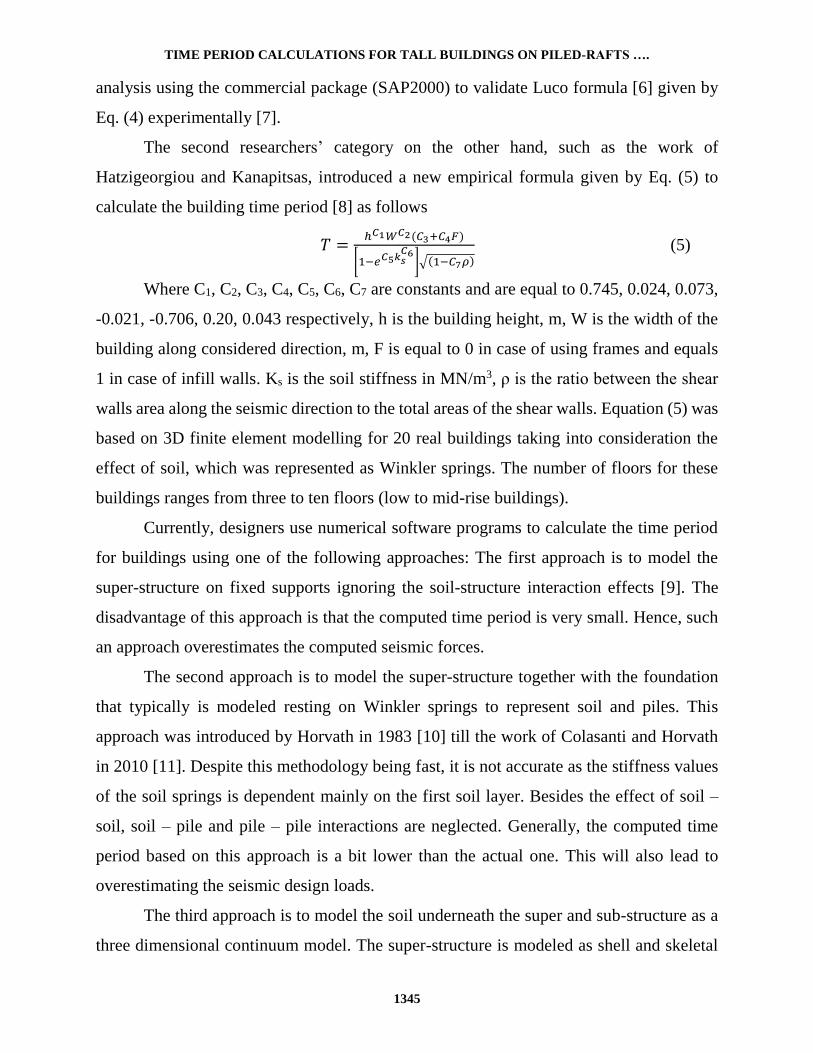
Each pile is modeled as cylindrical elements, each with constant friction along its
surface. In addition to two circular elements at its two extreme nodes to simulate the end
bearing at the bottom contact with soil and at the coupling degree of freedom postulated at
the top intersection with the raft area as shown in Fig. 2.
Pil
e (1
)
Pil
e (2
)
Vertical soil DOFsCoupling DOF
End bearing DOF
Fric
tio
n D
OF
s
Pil
e e
lem
en
t
L1
L2
L
Coupling DOF
End bearing DOF
Fric
tion
DO
Fs
Fig. 2. Degrees of freedom of piles-soil system.
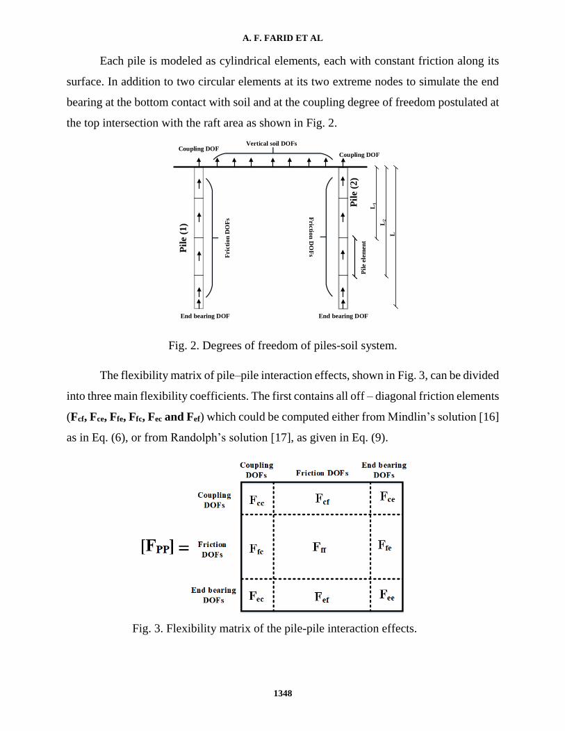
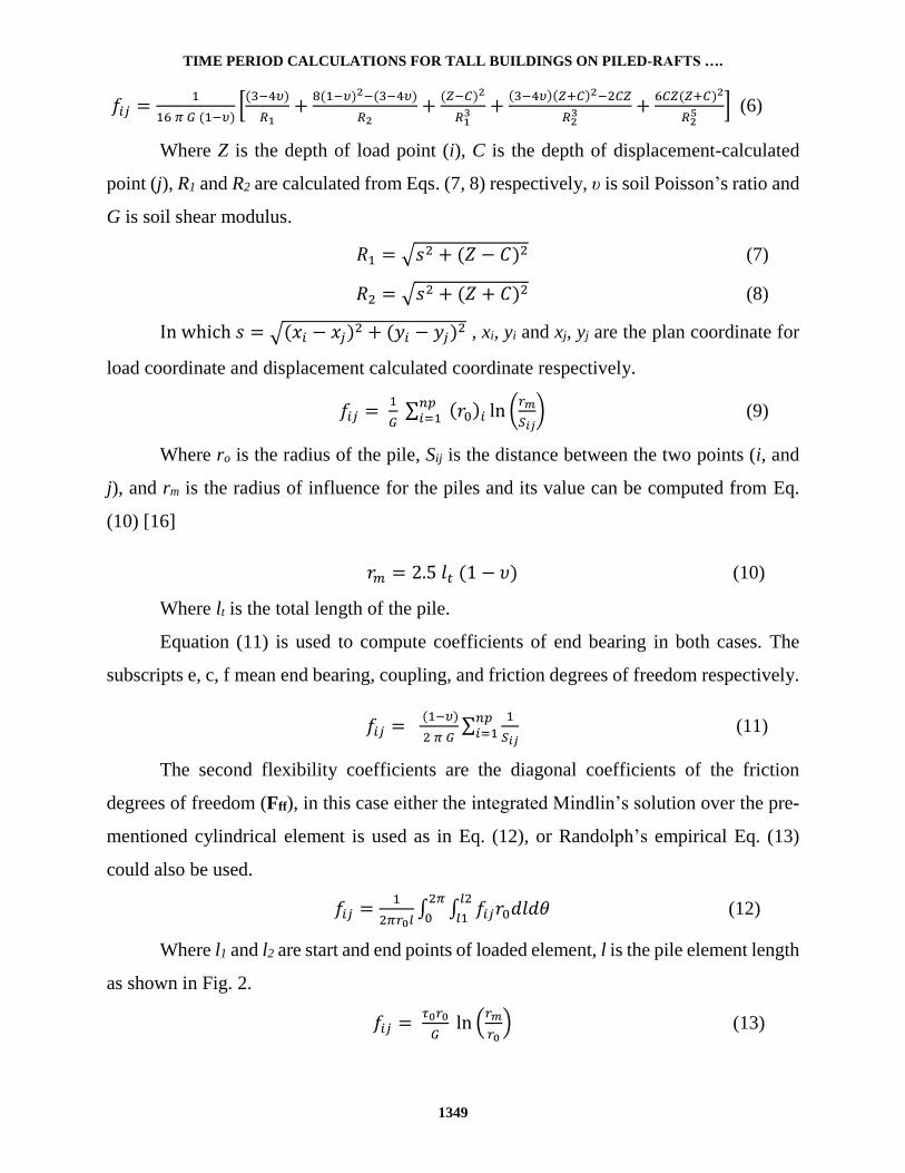
The flexibility matrix of pile–pile interaction effects, shown in Fig. 3, can be divided
into three main flexibility coefficients. The first contains all off – diagonal friction elements
(Fcf, Fce, Ffe, Ffc, Fec and Fef) which could be computed either from Mindlin’s solution [16]
as in Eq. (6), or from Randolph’s solution [17], as given in Eq. (9).
Fig. 3. Flexibility matrix of the pile-pile interaction effects.
TIME PERIOD CALCULATIONS FOR TALL BUILDINGS ON PILED-RAFTS ….
1349
𝑓𝑖𝑗 =1
16 𝜋 𝐺 (1−𝜐)[
(3−4𝜐)
𝑅1+
8(1−𝜐)2−(3−4𝜐)
𝑅2+
(𝑍−𝐶)2
𝑅13 +
(3−4𝜐)(𝑍+𝐶)2−2𝐶𝑍
𝑅23 +
6𝐶𝑍(𝑍+𝐶)2
𝑅25 ] (6)
Where Z is the depth of load point (i), C is the depth of displacement-calculated
point (j), R1 and R2 are calculated from Eqs. (7, 8) respectively, υ is soil Poisson’s ratio and
G is soil shear modulus.
𝑅1 = √𝑠2 + (𝑍 − 𝐶)2 (7)
𝑅2 = √𝑠2 + (𝑍 + 𝐶)2 (8)
In which 𝑠 = √(𝑥𝑖 − 𝑥𝑗)2 + (𝑦𝑖 − 𝑦𝑗)2 , xi, yi and xj, yj are the plan coordinate for
load coordinate and displacement calculated coordinate respectively.
𝑓𝑖𝑗 = 1
𝐺 ∑ (𝑟0)𝑖 ln (
𝑟𝑚
𝑆𝑖𝑗)
𝑛𝑝𝑖=1 (9)
Where ro is the radius of the pile, Sij is the distance between the two points (i, and
j), and rm is the radius of influence for the piles and its value can be computed from Eq.
(10) [16]
𝑟𝑚 = 2.5 𝑙𝑡 (1 − 𝜐) (10)
Where lt is the total length of the pile.
Equation (11) is used to compute coefficients of end bearing in both cases. The
subscripts e, c, f mean end bearing, coupling, and friction degrees of freedom respectively.
𝑓𝑖𝑗 = (1−𝜐)
2 𝜋 𝐺∑
1
𝑆𝑖𝑗
𝑛𝑝𝑖=1 (11)
The second flexibility coefficients are the diagonal coefficients of the friction
degrees of freedom (Fff), in this case either the integrated Mindlin’s solution over the pre-
mentioned cylindrical element is used as in Eq. (12), or Randolph’s empirical Eq. (13)
could also be used.
𝑓𝑖𝑗 =1
2𝜋𝑟0𝑙∫ ∫ 𝑓𝑖𝑗𝑟0𝑑𝑙𝑑𝜃
𝑙2
𝑙1
2𝜋
0 (12)
Where l1 and l2 are start and end points of loaded element, l is the pile element length
as shown in Fig. 2.
𝑓𝑖𝑗 = 𝜏0𝑟0
𝐺 ln (
𝑟𝑚
𝑟0) (13)
A. F. FARID ET AL
1350
The third stiffness coefficients are of the end bearing (Fee) together with those
corresponding to the integrated coupling degree of freedom (Fcc) obtained based on
Mindlin’s solution over circular element (as in Eq. (14)), or the Randolph’s equation as in
Eq. (15).
𝑓𝑖𝑗 =1
𝜋𝑟02 ∫ ∫ 𝑓𝑖𝑗𝑟0𝑑𝑟𝑑𝜃
𝑟0
0
2𝜋
0 (14)
𝑓𝑖𝑗 = (1−𝜐)
4 𝑟0 𝐺 (15)
In order to determine the interaction effects for pile-soil (FPS) and soil–soil (FSS)
interactions, the soil continuum is discretized into rectangular surface elements (boundary
elements) with only vertical degree of freedom. Mindlin’s Eq. [16] (recall Eq. (6)) is used
to obtain the flexibility matrix for these interactions.
Based on the previous equations, the total stiffness matrix [K] is calculated from the
inverse of the flexibility matrix [F] that includes all interaction effects (pile–pile, pile–soil,
and soil–soil interactions) as shown in Fig. 4. The PLPAK software [15] has a unique
capability to import any stiffness matrices. Therefore it is used in this work to read the
stiffness matrix that includes all interaction effects [K] and add it to the system of equations
of the modeled raft (which is previously modeled in the PLPAK). Now the piled-raft
foundation includes both the reaction of the vertical elements from the super-structure as
loads, and the stiffness matrix that represent all interaction effects. The deformation
underneath the super-structure vertical elements can be obtained. In the next section, the
proposed iterative technique and the calculation of the time period for the overall building
is discussed.

TIME PERIOD CALCULATIONS FOR TALL BUILDINGS ON PILED-RAFTS ….
1351
Fig. 4. Flexibility matrix of the overall system including all interaction effects.
3. THE PROPOSED EXTENSION
In this section, an extension of the work of Elmeliegy and Rashed [14] is presented.
This extension is mainly implemented to add the effect of piles in computing the time
period of a building. This is done by sub-structuring the overall building at the vertical
elements interface with the foundation as shown in Fig. 5. The overall building includes
two models: the first model is for the super-structure which is rested on fixed supports and
is solved using any commercial software. This is to obtain the reactions of the vertical
elements at the sub-structuring level. The second model, on the other hand, is for the sub-
structure and is solved using software (PLPAK). The raft is modeled as thick plate, the
piles are modeled as circular supporting areas, and the soil is modeled as internal
supporting areas. The interaction effects between piles and soil (pile-pile, pile-soil, and
soil-soil) are computed in an externally written computer code (as mentioned in section 2)
and imported to the PLPAK software as stiffness matrix.

A. F. FARID ET AL
1352
Fig. 5. The proposed sub-structuring technique of the super and the sub-structures.
The time period calculations for a piled-raft building including soil-structure
interaction effects is presented as follows: the first step is to carry out the 3D modelling for
the super-structure on fixed base using any finite element commercial software where the
slabs and shear walls are modeled as shell elements, while columns and beams are modeled
as frame elements. An initial analysis without lateral loads for determining the time period
of the super-structure is carried out. From the value of the computed time period the lateral
loads can be initially calculated according to any used design codes (for example ACI, EC,
ECP, etc.). In contrast to the lateral load, the dead and live loads are not affected by the
value of the computed time period. Then the model is reanalyzed, after adding the lateral
load values, to obtain the reactions of the vertical elements at the sub-structuring level.
EHS
Raft
Pil
esCoupling vertical
elements
Su
per
-str
uctu
re
Lateral loads
in X-dir
Lateral loads
in Y-dir
Su
b-s
tru
ctu
re
Sub-structuring
level
TIME PERIOD CALCULATIONS FOR TALL BUILDINGS ON PILED-RAFTS ….
1353
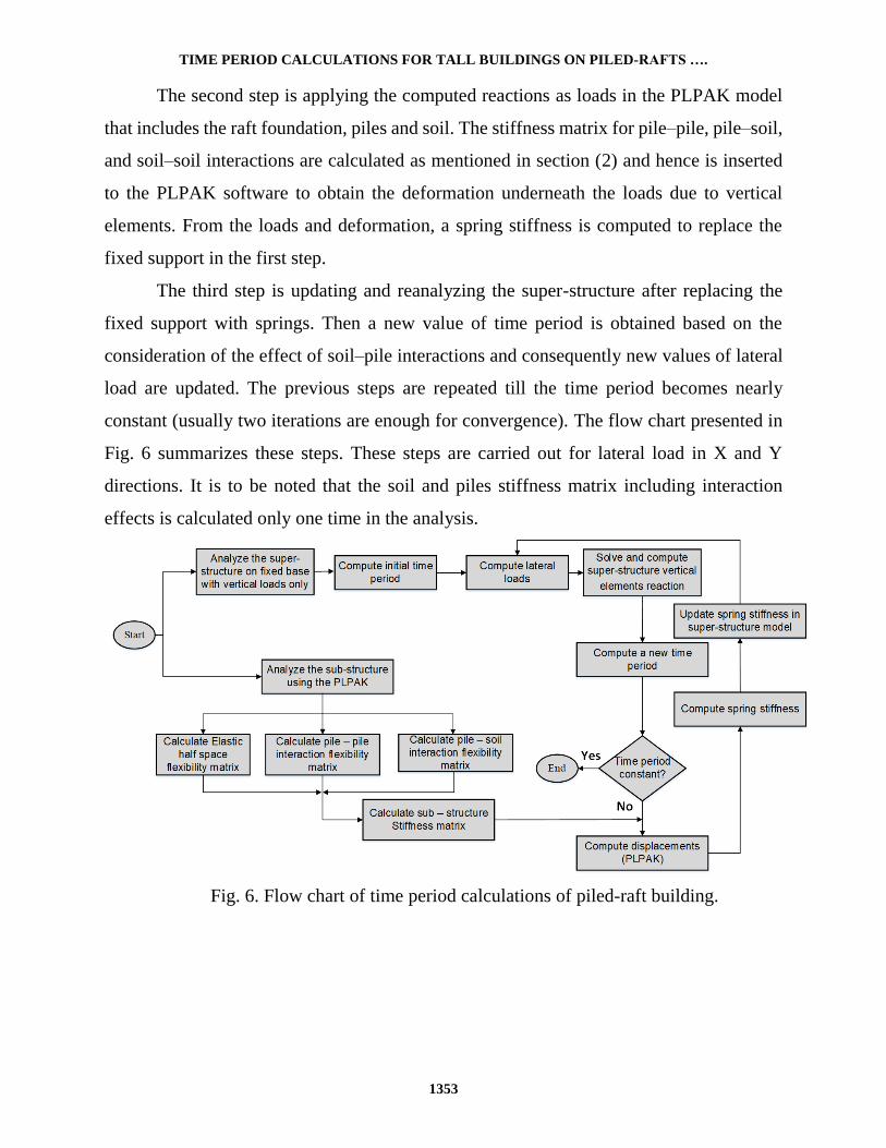
The second step is applying the computed reactions as loads in the PLPAK model
that includes the raft foundation, piles and soil. The stiffness matrix for pile–pile, pile–soil,
and soil–soil interactions are calculated as mentioned in section (2) and hence is inserted
to the PLPAK software to obtain the deformation underneath the loads due to vertical
elements. From the loads and deformation, a spring stiffness is computed to replace the
fixed support in the first step.
The third step is updating and reanalyzing the super-structure after replacing the
fixed support with springs. Then a new value of time period is obtained based on the
consideration of the effect of soil–pile interactions and consequently new values of lateral
load are updated. The previous steps are repeated till the time period becomes nearly
constant (usually two iterations are enough for convergence). The flow chart presented in
Fig. 6 summarizes these steps. These steps are carried out for lateral load in X and Y
directions. It is to be noted that the soil and piles stiffness matrix including interaction
effects is calculated only one time in the analysis.
Fig. 6. Flow chart of time period calculations of piled-raft building.

A. F. FARID ET AL
1354
4. NUMERICAL EXAMPLE
In this section, the verification example shown in Fig. 7 is considered. This example
is solved three times to represent 10, 15 and 20 typical floors considering the analysis in
X-direction only. Shear walls (solid black lines in Fig. 7) are assumed with these size to
fulfill the ECP 201 [3] code requirement with restriction (time period shall not exceeds 4
seconds). The building is rested on piled-raft foundation as shown in Fig. 8. Five different
analytical models are demonstrated for the purpose of comparison and to demonstrate the
effect of considering the soil–structure interaction:
1- Model (1): 3D finite element model for the super-structure supported on fixed supports
as shown in Fig. 9. This model is commonly used in the design offices. In this model
floors, columns/beams, and walls/cores are modeled as plate, frame, and shell elements
respectively.
2- Model (2): 3D finite element model for the super-structure as in model (1). The piles
are represented by Winkler springs; the stiffness values of the piles are obtained from
the Egyptian code of practice for deep foundations (ECP 202/4) [18]. This is done by
calculating the allowable capacity divided by the allowable settlement of a single pile.
3- Model (3): Using manual calculations as time period is computed based on the
empirical Eq. (5) according to Hatzigeorgiou and Kanapitsas [8].
4- Model (4): 3D finite element model for both the super-structure (as shell and frame
elements) and for the sub-structure (raft as 4-node shell elements, soil as 8-node solid
elements and piles as frame elements). The three translation DOFs of the shell element
node are compatible with the corresponding three translation DOFs in the solid element.
However, the two rotations DOFs in the shell element will not transmitted to the solid
elements, because the soil does not transmit rotations, in addition these DOFs are
transmitted through the shell elements. Piles were modeled as frame elements linked
through the depth of the solid element (soil) and linked to the shell elements at nodes
(raft). The soil block dimensions under the raft are 57 × 58 × 15 m. The solid elements
discretization is taken 1.0 ×1.0 ×1.0 m under the foundation and is transmitted to be 2.0
×2.0 ×1.0 m outside the foundation using transition elements as shown in Fig. 10. Piles
TIME PERIOD CALCULATIONS FOR TALL BUILDINGS ON PILED-RAFTS ….
1355
are discretized into 1 m element along its length. Displacements are prevented in the
far field, and rigid layer is added at 15 m depth.
5- Model (5): similar to model (4) but with finer solid element mesh in which the mesh is
doubled.
6- Model (6): represents the present work solution by coupling the super and sub-
structures as proposed in section 3. Figure 11 demonstrates the piled-raft boundary
element model with loads from (reactions of) super-structure vertical elements.
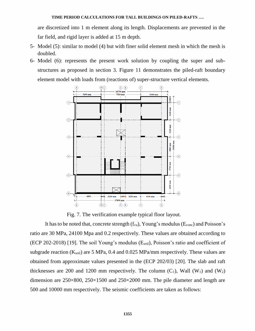
Fig. 7. The verification example typical floor layout.
It has to be noted that, concrete strength (fcu), Young’s modulus (Econc) and Poisson’s
ratio are 30 MPa, 24100 Mpa and 0.2 respectively. These values are obtained according to
(ECP 202-2018) [19]. The soil Young’s modulus (Esoil), Poisson’s ratio and coefficient of
subgrade reaction (Ksoil) are 5 MPa, 0.4 and 0.025 MPa/mm respectively. These values are
obtained from approximate values presented in the (ECP 202/03) [20]. The slab and raft
thicknesses are 200 and 1200 mm respectively. The column (C1), Wall (W1) and (W2)
dimension are 250×800, 250×1500 and 250×2000 mm. The pile diameter and length are
500 and 10000 mm respectively. The seismic coefficients are taken as follows:

A. F. FARID ET AL
1356
Seismic zone factor is 0.125 g
Importance factor is 1.00
Resistance factor 5.00
Soil type is a type (D), i.e. weak soil
Damping factor is 1.00
Fig. 8. The foundation piled-raft layout of the verification example.
The periodic time value for the five models with different number of floors is shown
in Table 1. The value of the base shear according to the Egyptian code of practice (ECP
201-2012) [3] are demonstrated in Table 2. A major parameter besides the computation of
base shear value is the time consumed to solve the problem. Table 3 demonstrates such a
time for each model.
It can be seen that, the time period value for the above-mentioned models is
dramatically changed by considering interaction effects. Building design code
underestimates the value of the time period and consequently gives a high value of the
design base shear. In addition, using Winkler springs to represent soil or piles still
underestimate the value of the time period. Using Eq. (5) [8] gives better values than
Winkler springs values however it still underestimates the values of the time period. The
present model solution gives comparable results to those of the refined 3D finite elements
analysis; however, the later consumes huge computational effort and time.

TIME PERIOD CALCULATIONS FOR TALL BUILDINGS ON PILED-RAFTS ….
1357
Fig. 9. Detailed 3D finite element model for fixed base super-structure (model 1).
Fig. 10. Detailed 3D finite element model including soil as solid element (model 4).

A. F. FARID ET AL
1358
Fig. 11. Boundary element model for piled-raft with the vertical element reactions
(model 6).
Table 1. The periodic time (in seconds) for the different models.
Number
of floors
Value
according to
ECP code
Fixed
base
Model (1)
Winkler
springs
Model (2)
Equation (5)
Ref. [8]
Model (3)
3D solid
elements
1×1×1 m
Model (4)
3D solid
elements
0.5×0.5×0.5 m
Model (5)
Proposed
technique
Model (6)
10 0.64 0.93 1.63 1.33 2.97 2.85 2.72
15 0.87 1.28 1.89 1.80 3.71 3.35 2.95
20 1.07 1.77 2.25 2.23 4.15 3.93 3.81
Table 2. The base shear (in tons) for the different models.
Number
of floors
Value
according to
ECP code
Fixed
base
Model (1)
Winkler
springs
Model (2)
Equation (5)
Ref. [8]
Model (3)
3D solid
elements
1×1×1 m
Model (4)
3D solid
elements
0.5×0.5×0.5 m
Model (5)
Proposed
technique
Model (6)
10 138.37 119 79.9 83.23 48.23 48.23 48.23
15 190.86 129.72 103.36 108.52 72.35 72.35 72.35
20 206.91 147.15 102.9 104.75 96.47 96.47 96.47
Table 3. The time (in minutes) for analysis of different models.
Number
of floors
Value
according to
ECP code
Fixed
base
Model (1)
Winkler
springs
Model (2)
Equation (5)
Ref. [8]
Model (3)
3D solid
elements
1×1×1 m
Model (4)
3D solid
elements
0.5×0.5×0.5 m
Model (5)
Proposed
technique
Model (6)
10 --- 5 5 --- 240 1140 32
15 --- 8 8 --- 360 1400 40
20 --- 12 12 --- 480 1680 55

TIME PERIOD CALCULATIONS FOR TALL BUILDINGS ON PILED-RAFTS ….
1359
5. CONCLUSIONS
This paper presents the calculation of time period of tall buildings over piled-rafts
taking into consideration the soil-structure interaction effects, such as soil–soil, soil–pile
and pile–pile interactions. Super-structure was modeled using any commercial finite
element software, whereas the soil was modeled as an elastic half space model, which is
implemented in the boundary element software (PLPAK), the piles were modeled as a
circular support area and the interaction effects were imported as stiffness in the used
boundary element software. Time period calculation was carried out using an iterative
technique. A verification example was presented and results demonstrated the effect of
considering the SSI on calculating the time period. It was shown that the computed values
differ by 292%, 230%, and 215% in the case of 10, 15, and 20 floors respectively compared
to those obtained considering fixed base. This lead to decrease the base shear value to about
59.5%, 44%, and 34.5% for 10, 15, and 20 floors building respectively compared to those
obtained considering fixed base. It has to be noted that the proposed technique computes
values of the time period very close to the full 3D finite element model but with
dramatically less computational time and effort. A designer can make use of the present
work in this manuscript from the following link http://www.be4e.com/new/Iterative.html.
ACKNOWLEDGEMENTS
This project was supported financially by the Science and Technology Development
Fund (STDF), Egypt, Grant No AHRC 30794. The first and third authors would like to
acknowledge this support.
DECLARATION OF CONFLICT OF INTERESTS
The authors have declared no conflict of interests.
REFERENCES
1. ASCE, “Minimum Design Loads for Buildings and Other Structures”, American
Society of Civil Engineers, Virginia, USA, 2010.

A. F. FARID ET AL
1360
2. EC8, “Eurocode 8 – Design of Structures for Earthquake Resistance. Part 1: General
Rules, Seismic Action and Rules for Buildings”, European Committee for
Standardization, EN 1998 – 1, Brussels, Belgium, 2004.
3. ECP 201, Egyptian Code for Calculating Loads and Forces in Structural Work and
Masonry”, Housing and Building National Research Center, Ministry of Housing,
Utilities and Urban Planning, Cairo, Egypt, 2012.
4. Kwon, O., and Kim, E., “Evaluation of Building Period Formulas for Seismic
Design”, Journal of Earthquake Engineering and Structural Dynamics, Vol. 39, pp.
1569-1583, 2010.
5. Dunkerley, S., “On the Whirling and Vibration of Shafts”, Journal Philosophical
Transaction of Royal Society, Vol. 185, pp. 279-360, 1894.
6. Luco, J. E., “Bounds for Natural Frequencies, Dunkerley’s Formula and Application
to Soil-Structure Interaction”, Journal of Soil Dynamics and Earthquake Engineering,
Vol. 47, pp. 32-37, 2013.
7. Xiong, W., Jiang, L., and Li, Y., “Influence of Soil – Structure Interaction
(Structure-to-Soil Relative Stiffness and Mass Ratio) On the Fundamental Period of
Buildings: Experimental Observation and Analytical Verification”, Bulletin of
Earthquake Engineering, Vol. 14, No. 1, pp. 139-160, 2016.
8. Hatzigeorgiou, G. D., and Kanapitsas, G., “Evaluation of Fundamental Period of
Low‐rise and Mid‐rise Reinforced Concrete Buildings”, Journal of Earthquake
Engineering and Structural Dynamics, Vol. 42, No. 11, pp. 1599-1616, 2013.
9. Abdelwahab, M. A., Rashed, Y. F., and Mukhtar, A. A., “Time History Boundary
Element Analysis of Multi Story Buildings”, Journal of Engineering and Applied
Science, Vol. 62, No. 2, pp. 165-185, 2015.
10. Horvath, J. S., “New Subgrade Model Applied to Mat Foundations”, Journal of
Geotechnical Engineering, Vol. 109, No. 12, pp. 1567-1587, 1983.
11. Colasanti, R. J., and Horvath, J. S., “Practical Subgrade Model for Improved Soil-
Structure Interaction Analysis: Software Implementation”, Practice Periodical on
Structural Design and Construction”, Vol. 15, No. 4, pp. 278-286, 2010.
12. Hemsly, J., “Elastic Solutions for Axisymmetric Loaded Circular Raft with Free and
Clamped Edges Founded on Winkler Springs or a Half-Space”, Proceedings of the
Institution of Civil Engineers, Vol. 83, No. 1, pp. 61-90, 1987.
13. Jeong, S. J., and Cho, J., “Interactive 3D Analysis Method of Piled Raft Foundation
for High – Rise Buildings”, Proceedings of the 18th International Conference on Soil
Mechanics and Geotechnical Engineering, Vol. 18, pp. 2763-2766, 2013.
14. Elmeliegy, A. M., and Rashed, Y. F., “Efficient Preconditioned Soil-Foundation-
Structure Interaction Approach to Compute Tall-Building Time Period”, Journal
American Society of Civil Engineers, Vol. 24, No. 3, pp. 1-13, 2019.
15. Rashed, Y. F., “A Boundary/Domain Element Method for Analysis of Building Raft
Foundation”, Journal of Engineering Analysis of Boundary Elements, Vol. 29, No. 9,
pp. 859-877, 2005.
TIME PERIOD CALCULATIONS FOR TALL BUILDINGS ON PILED-RAFTS ….
1361
16. Wang, C. M., Chow, Y. K., and How, Y. C., “Analysis of Rectangular Thick Rafts
on an Elastic Half Space”, Journal of Computers and Geotechnics, Vol. 28, No. 3, pp.
161-184, 2001.
17. Randolph, M. F., and Worth, C. P., “Analysis of Deformation of Vertically Loaded
Piles”, Journal of Geotechnical Engineering Division ASCE, Vol. 104, pp. 1465-
1488, 1978.
18. ECP 202, “Egyptian Code for Soil Mechanics Design and Construction of
Foundations, Part 4, Deep Foundations”, Housing and Building National Research
Center. Ministry of Housing, Utilities and Urban Planning, Cairo, Egypt, 2005.
19. ECP 203, “Egyptian Code for Practice and Design of Concrete Structures, Housing
and Building National Research Center, Ministry of Housing, Utilities and Urban
Planning, Cairo, Egypt, 2018.
20. ECP 202, “Egyptian Code for Soil Mechanics—Design and Construction of
Foundations, Part 3, Shallow Foundations”, Housing and Building National Research
Center, Ministry of Housing, Utilities and Urban Planning, Cairo, Egypt, 2005.
لبش خازوقية علىالتأثير المتبادل بين التربة والمنشأ على حسابات الزمن الدوري للمباني العالية المرتكزة تم في البحث حساب الزمن الدوري للمباني العالية والتي ترتكز على لبش خازوقيه وبما في ذلك التأثير
بين التربة ازوق والخازوق و بين الخازوق والتربة و التبادلي بين التربة والمنشأ، شاملا التأثير التبادلي بين الخوالتربة من خلال تطوير طريقة اقتران ثنائية التكرار بين المنشأ فوق وتحت سطح التربة حيث تم تمثيل المنشأ فوق سطح التربة باستخدام أي برنامج للحاسب يستخدم طريقة العناصر المحدودة، في حين يتم تمثيل المنشأ
ربة بما في ذلك أساس المبنى باستخدام برنامج مطور يستخدم طريقة العناصر الحدودية تحت سطح الت(PLPAKوقد ثبت أن أخذ التأثير المتبادل بين المنشأ والتربة في الاعتبار ) قيم الزمن يزيد بشكل كبير من
الدوري للمنشأ وبالتالي يقلل من القوى التصميمية للزلازل.
Related Documents