1 Abstract—The deployment of wireless technologies in industrial networks is very promising mainly due to their inherent flexibility. However, current wireless solutions lack the capability to provide the deterministic, low delay service required by many industrial applications. Moreover, the high level of interference generated by industrial equipment limits the coverage that ensures acceptable performance. Multi-hop solutions, when combining frame forwarding with higher node density, have the potential to provide the needed coverage while keeping radio communication range short. However, in multi- hop solutions the medium access time at each of the nodes traversed additively contributes to the end-to-end delay and the forwarding delay (i.e., the time required for packets to be processed, switched, and queued) at each node is to be added as well. This paper describes Time-driven Access and Forwarding (TAF), a solution for guaranteeing deterministic delay, at both the access and forwarding level, in wireless multi-hop networks, analyzes its properties, and assesses its performance in industrial scenarios. Index Terms—Industrial networks, wireless networks, medium access control, pipeline forwarding. I. INTRODUCTION Wireless technologies have achieved a wide diffusion in the past few years: they are deployed in Local and Personal Area Networks (LANs/PANs) — with a large number of different applications such as enterprise networking, home entertainment, healthcare, and telemedicine — as well as in Wide Area Networks (WANs), mainly used for long range point-to-point interconnectivity or as access technology in scarcely populated areas. Such success stems from their flexibility and their providing an inexpensive way (compared to traditional wired networks) to interconnect devices with support for mobility and easy reconfiguration. The same motivations are at the basis of the current trend that is taking wireless technologies to the industrial environment. Flexibility, ease of network reconfiguration, short deployment time, lower costs, possibility to connect sensors that cannot be reached by wired networks are the main advantages of wireless technologies and fostering their adoption in the industrial scenario [1]-[4]. Today factories need the industrial process to be flexible enough to efficiently support seamless modifications of production lines (due to the short life cycle of products) and high product customization (in order to meet Manuscript received September 30, 2008. demanding customer requirements). Wireless technologies enable easy reconfiguration of the factory floor with low costs, thus reducing the time to market and increasing the competitiveness of the company. In particular, with a carefully planned wireless network covering an entire factory, devices can be seamlessly moved as connectivity is guaranteed at any specific position. In this context, a great potential is offered by wireless multi-hop networks, which entirely eliminate the need for cabling. The typical network architecture consisting of a wired backbone with one or more wireless access links can be substituted with a completely wireless network where packets are forwarded through multiple wireless links towards the destination. Additionally, wireless multi-hop networks are key to reduce the high Bit Error Rate (BER) typically tainting wireless channels in the industrial environment due to the interferences of industrial devices such as electric motors and actuators. In fact, a possible solution to this issue is offered by intermediate hops being placed between distant wireless terminals to forward packets on shorter (and hence more reliable and stable) wireless links [5]. The multi-hop paradigm is also widely utilized in Wireless Sensor Networks (WSN), where sensors have to rely on forwarding features of the other nodes in order to reach a central controller or the actuators because of their reduced-in-depth transmission capabilities [4]. Another interesting application scenario for wireless multi-hop networks is to support disaster relief operations, as rescue teams need a quickly deployable reliable and cost effective network [6]. One of the main challenges faced by industrial (multi-hop) wireless communications is the provision of deterministic quality of service (QoS) in terms of delay, jitter, and packet loss. In fact, factory applications have hard real-time requirements which are difficult to satisfy, especially at device intercommunication level, where controllers, sensors, and actuators have to exchange data with strict latency constraints. This paper presents Time-driven Access and Forwarding (TAF), a solution for efficiently deploying Time Division Multiple Access (TDMA) in multi-hop networks jointly with Pipeline Forwarding [13], a packet scheduling technique originally proposed in the context of wired global networks. The paper shows how the combination of TDMA and Pipeline Forwarding ensures low deterministic end-to-end delay and controlled jitter to real-time traffic across multiple wireless hops, thus resulting very attractive for the industrial scenario. Nodes use a Common Time Reference (CTR) to drive end-to- Time driven Access and Forwarding for industrial wireless multi-hop networks Mario Baldi , Member, IEEE, Riccardo Giacomelli, Member, IEEE, Guido Marchetto, Member, IEEE

Welcome message from author
This document is posted to help you gain knowledge. Please leave a comment to let me know what you think about it! Share it to your friends and learn new things together.
Transcript

1
Abstract—The deployment of wireless technologies in
industrial networks is very promising mainly due to their inherent flexibility. However, current wireless solutions lack the capability to provide the deterministic, low delay service required by many industrial applications. Moreover, the high level of interference generated by industrial equipment limits the coverage that ensures acceptable performance. Multi-hop solutions, when combining frame forwarding with higher node density, have the potential to provide the needed coverage while keeping radio communication range short. However, in multi-hop solutions the medium access time at each of the nodes traversed additively contributes to the end-to-end delay and the forwarding delay (i.e., the time required for packets to be processed, switched, and queued) at each node is to be added as well. This paper describes Time-driven Access and Forwarding (TAF), a solution for guaranteeing deterministic delay, at both the access and forwarding level, in wireless multi-hop networks, analyzes its properties, and assesses its performance in industrial scenarios.
Index Terms—Industrial networks, wireless networks, medium
access control, pipeline forwarding.
I. INTRODUCTION Wireless technologies have achieved a wide diffusion in the
past few years: they are deployed in Local and Personal Area Networks (LANs/PANs) — with a large number of different applications such as enterprise networking, home entertainment, healthcare, and telemedicine — as well as in Wide Area Networks (WANs), mainly used for long range point-to-point interconnectivity or as access technology in scarcely populated areas. Such success stems from their flexibility and their providing an inexpensive way (compared to traditional wired networks) to interconnect devices with support for mobility and easy reconfiguration. The same motivations are at the basis of the current trend that is taking wireless technologies to the industrial environment. Flexibility, ease of network reconfiguration, short deployment time, lower costs, possibility to connect sensors that cannot be reached by wired networks are the main advantages of wireless technologies and fostering their adoption in the industrial scenario [1]-[4]. Today factories need the industrial process to be flexible enough to efficiently support seamless modifications of production lines (due to the short life cycle of products) and high product customization (in order to meet
Manuscript received September 30, 2008.
demanding customer requirements). Wireless technologies enable easy reconfiguration of the factory floor with low costs, thus reducing the time to market and increasing the competitiveness of the company. In particular, with a carefully planned wireless network covering an entire factory, devices can be seamlessly moved as connectivity is guaranteed at any specific position.
In this context, a great potential is offered by wireless multi-hop networks, which entirely eliminate the need for cabling. The typical network architecture consisting of a wired backbone with one or more wireless access links can be substituted with a completely wireless network where packets are forwarded through multiple wireless links towards the destination. Additionally, wireless multi-hop networks are key to reduce the high Bit Error Rate (BER) typically tainting wireless channels in the industrial environment due to the interferences of industrial devices such as electric motors and actuators. In fact, a possible solution to this issue is offered by intermediate hops being placed between distant wireless terminals to forward packets on shorter (and hence more reliable and stable) wireless links [5]. The multi-hop paradigm is also widely utilized in Wireless Sensor Networks (WSN), where sensors have to rely on forwarding features of the other nodes in order to reach a central controller or the actuators because of their reduced-in-depth transmission capabilities [4]. Another interesting application scenario for wireless multi-hop networks is to support disaster relief operations, as rescue teams need a quickly deployable reliable and cost effective network [6].
One of the main challenges faced by industrial (multi-hop) wireless communications is the provision of deterministic quality of service (QoS) in terms of delay, jitter, and packet loss. In fact, factory applications have hard real-time requirements which are difficult to satisfy, especially at device intercommunication level, where controllers, sensors, and actuators have to exchange data with strict latency constraints.
This paper presents Time-driven Access and Forwarding (TAF), a solution for efficiently deploying Time Division Multiple Access (TDMA) in multi-hop networks jointly with Pipeline Forwarding [13], a packet scheduling technique originally proposed in the context of wired global networks. The paper shows how the combination of TDMA and Pipeline Forwarding ensures low deterministic end-to-end delay and controlled jitter to real-time traffic across multiple wireless hops, thus resulting very attractive for the industrial scenario. Nodes use a Common Time Reference (CTR) to drive end-to-
Time driven Access and Forwarding for industrial wireless multi-hop networks
Mario Baldi , Member, IEEE, Riccardo Giacomelli, Member, IEEE, Guido Marchetto, Member, IEEE

2
end packet forwarding, so that contentions are avoided both at the medium access level and at the forwarding level in multi-hop paths. Furthermore, TAF guarantees communication robustness by supporting mesh topologies where multiple paths to each destination are possible and can be used in the case a failure occurs at a node or link. This topology, together with the multi-hop operation, also sensibly reduces losses due to external interferences. TAF is designed for deployment in a manufacturing plant where nodes either are fixed, or have nomadic mobility (e.g., plant reconfiguration) or move in a small area compared to the wireless coverage (e.g., nodes placed on articulated arms or servo systems).
Notwithstanding the large number of technologies potentially available for deployment in industrial wireless networks, the IEEE 802.11 standard is used in the rest of this paper — as both a comparison baseline and a technological platform for the implementation of the proposed solution — because of its reduced deployment costs. In fact, IEEE 802.11 networks are relatively simple to engineer and provide high flexibility and wide transmission ranges if compared to other wireless standards for local area networks. Furthermore, this favored a wide adoption of the IEEE 802.11 standard, with consequent economy of scale impacting the cost of components. The paper shows how TAF can be deployed to significantly improve the performance of IEEE 802.11-based wireless multi-hop networks in terms of end-to-end delay, thus opening the path to a wide adoption of this standard in the industrial environment. However, TAF is more general, i.e., independent of the underlying wireless technology, and could be deployed to similarly improve the performance of multi-hop wireless networks based on any other technology, such as IEEE 802.15.4, Bluetooth.
The purpose of this work is to define node operating principles and network architecture required to properly support time-driven access and forwarding, thus avoiding losses and extra delays due to network congestion. However, some other aspects, such as external interferences (that, although can be limited thanks to the multi-hop network operation, have to be taken into account in an industrial environment) and routing need to be carefully studied prior to actual deployment. This paper provides a discussion of how the most significant solutions to cope with interferences proposed so far in (industrial) wireless networks can be applied also when TAF is deployed. However, the novelty of TAF operating principles opens the way to the definition of new specific, possibly more effective, solutions. While these require extensive study that is left to future works, guidelines for the development of some such specialized mechanisms are provided.
The rest of the paper is organized as follows. Section II motivates the work by describing the state-of-the-art. Section III describes pipeline forwarding, the operating principles of TAF, and a possible TAF implementation based on IEEE 802.11. This section also elaborates on routing, scheduling, and solutions to cope with external interferences. Section IV focuses on network synchronization, which is
necessary to implement TAF. Section V reports on simulation results. Conclusions are drawn in Section VI before summarizing the possible future work in this context.
II. RELATED WORK AND MOTIVATIONS Previous work [7] showed how traditional Carrier Sense
Multiple Access (CSMA) based networks perform poorly when adopted in a factory environment. In particular, [7] shows that data transfer over a single-hop IEEE 802.11e (i.e., the QoS-enabled extension of the IEEE 802.11 standard) wireless local area network is characterized by latencies of hundreds of milliseconds without any guarantee). These poor results are mainly due to the non real-time nature of IEEE 802.11 algorithms, which have been designed for traditional applications that do not have strict QoS requirements, i.e., they are tolerant to packet losses (as with multimedia applications, like videoconferencing and video streaming), and admit delay/jitter bounds of several hundreds of milliseconds (as with data applications like web browsing and file transfer). CSMA-based solutions get even worse in a multi-hop wireless network scenario. First of all, node density, which is advisable in an industrial network as mentioned above, affects access delay (a well as throughput), as it is the case for any contention-based MAC. Second, on a multiple-hop path the access delay at each hop additively contributes to the end-to-end delay. Last but not least, queuing delay is further introduced at each hop when multiple packets are to be forwarded on the same wireless link between two wireless nodes.
A possible solution to provide QoS guarantees- in a single-hop wireless network is the adoption of a TDMA-based medium access protocol, where nodes access the network at well defined instants, thus avoiding contentions and collisions. This approach is currently successfully adopted in some Controller Area Network (CAN) buses (e.g., TTP/C [8] and FlexRay [9]) and has been recently proposed for industrial wireless communications as well. One such example is the Wireless Interface for Sensors and Actuators (WISA) [10] according to which nodes, connected in a star topology, access the network during predefined time slots. WISA developers implemented an optimized TDMA over the IEEE 802.15.1 physical layer, thus enabling a cost effective deployment as conventional IEEE 802.15.1 radio transceivers can be adopted. IEEE 802.11 natively supports time based medium access within the Point Coordination Function (PCF) — and also within the Hybrid Coordination controlled Channel Access (HCCA) featured by the QoS-enabled extension IEEE 802.11e. However, all these solutions are designed for a centralized scenario where a coordination point, usually an access point, schedules data transmissions and cannot be deployed in the wireless mesh topologies typical of multi-hop communications.
The Time-driven Access and Forwarding (TAF) solution proposed in this paper includes a time-driven medium access mechanism that does not rely on a centralized coordinator, thus being suitable as a TDMA solution in mesh topologies.

3
Furthermore, by utilizing time information in the network, TAF eliminates contention at both the access and the forwarding level, thus avoiding the abovementioned bandwidth waste and long delay. The paper also proposes and evaluates a distributed allocation procedure deployed to guarantee a contention free service in TDMA based wireless mesh networks.
The deployment of a TDMA solution in mesh topologies in the industrial environment is also a key feature of the upcoming ISA-SP100 standard. Since the standardization work by Instrumentation, System, and Automation society (ISA) is still in progress, available information is very limited. However, preliminary public data show how the upcoming release (i.e., ISA-SP100.11a) will focus on soft real-time applications tolerating delays on the order of 100 ms (see Section V.C of [4] for an ISA-SP100 overview). Hence, TAF is somewhat orthogonal to ISA-SP100; rather, TAF could be seen as a candidate solution for further releases aiming at an improvement on ISA-SP100.11a performance in terms of end-to-end latency.
One of the basic ideas underlying TAF is the deployment of Pipeline Forwarding [13] in network nodes to move packets at predefined instants across several hops. A similar approach is adopted in Synchronous TDMA [11][12], which was proposed subsequently to PF for usage in industrial wired networks. In Synchronous TDMA, routers connecting different IP subnets forward packets during time slots assigned, as in a PF network, to each flow during a resource reservation phase. An optimized architecture for packet routers is also proposed with the aim of minimizing the pass-through delay experienced by packets in a router. Hence, TAF, by deploying time-based packet forwarding in a wireless multi-hop network, can be seen as building upon Synchronous TDMA as much as Pipeline Forwarding. The resource reservation presented here for TAF differs from the ones proposed for Pipeline Forwarding and Synchronous TDMA as it has to account for the shared nature of the wireless channel (see Section III.E). Furthermore, this work analyzes tolerance to node synchronization inaccuracy, not considered in the literature on Synchronous TDMA.
III. KEY ELEMENTS AND OPERATING PRINCIPLES In order to guarantee deterministic QoS in terms of end-to-
end delay and packet loss in wireless multi-hop networks, Time-driven Access and Forwarding (TAF) relies on nodes having a Common Time Reference (CTR) to drive both access to the wireless links and forwarding along multi-hop paths. A CTR-based TDMA scheme is adopted as medium access scheme and Pipeline Forwarding (PF) is deployed at nodes with packet forwarding capabilities. The operating principles of TAF and a possible implementation in the context of an IEEE 802.11e network are presented in this section. In particular, Section A introduces the basic principles of a CTR-based TDMA scheme, while Section B introduces and describes pipeline forwarding. Section D addresses scheduling of TF across the network that is required within both routing
and resource reservation, presented and assessed in Section C and Section E, respectively. Section F, after introducing relevant IEEE 802.11e elements, provides the guidelines for a possible IEEE 802.11-based implementation of TAF. Section G provides an analytical evaluation of the end-to-end delay achieved by TAF. Finally, Section H elaborates on issues related to external interferences both discussing how general solution can be applied when TAF is deployed and outlining possible TAF specific solutions.
A. TAF Medium Access function (TAF-MA) TAF includes a Medium Access function (TAF-MA)
implementing a TDMA scheme based on a Common Time Reference (CTR). In particular, all network nodes utilize a common basic time period called time frame (TF) to drive medium access. TFs are grouped into time cycles (TCs) that reoccur periodically and are aligned in all nodes. For example, Fig. 1 shows a CTR where the 125-μs TF duration fT is obtained by dividing a 12.5 ms TC in a sequence of 100 TFs.
125 μs
Time1 2 100
TimeCycle0
1 2 100
TimeCycle1
1 2 100
TimeCycle 79
fTfTfTfT fT
12.5 ms
125 μs
Time1 2 100
TimeCycle0
1 2 100
TimeCycle1
1 2 100
TimeCycle 79
fTfTfTfT fT
12.5 ms
Fig. 1. Common time reference structure
Each TF can be reserved for a unicast transmission between two nodes or a broadcast transmission from one node to all the nodes in its transmission range. A TF reservation is periodic, i.e., repeated each TC. Hence, the TC duration has to be a multiple of the longest periodicity characterizing the applications deployed on the network. Shorter periodicities are obtained by reserving groups of TFs within the same TC. Notice that TC and TF duration can be reconfigured at any time in order to adapt to modifications in the network scenario. TF reservations are valid for all nodes within the interfering area of the transmitter. On the other hand, two non-interfering nodes can transmit simultaneously (with or without reservation), thus enabling spatial reuse. During unreserved TFs nodes try to gain control of the channel utilizing MAC contention mechanisms of the underlying wireless technology (e.g., CSMA with exponential back-off in the case of standard IEEE 802.11).
TAF-MA does not need a central coordination point: reservation information is not centrally maintained, but spread across nodes in allocation tables. The allocation table maintained by every node is updated during the reservation procedure described in Subsection E and contains a row for each TF storing the type of traffic (pipelined or non-pipelined, see the following section) for which the TF has been reserved, the node having the right to transmit during that TF, the node that is supposed to receive the transmission, other information required to properly handle TF reservations, and the amount

4
of bits not yet reserved.
B. TAF forwarding function: Pipeline Forwarding (PF) One of the key contributions of this paper is to combine
TDMA with Pipeline Forwarding (PF) [13], a.k.a. pseudo-isochronous forwarding, adopted to implement the forwarding function in TAF to provide deterministic end-to-end QoS to real-time traffic. PF is a packet scheduling technique originally proposed in the context of wired global networks. In PF, a resource reservation phase (discussed, together with specific issues arising in the context of wireless multi-hop networks, in the following subsections) is required to allocate to each flow requiring a deterministic service one or more p-TFs, or pipeline-forwarding-TFs on each link along its path to enable pipeline forwarding of packets. This results in a periodic schedule, repeated every TC, for packets to be switched and forwarded by each node along the path. The basic PF operation is regulated by two simple rules: (i) all packets that must be forwarded in TF m by a node must be in its output port buffers at the end of TF 1m − , and (ii) a packet p transmitted in TF m by node iN must be transmitted in TF m τ+ by node, 1iN + where τ is an integer constant called forwarding delay. The value of the forwarding delay is determined at resource-reservation time and must be large enough to satisfy rule (i) given the propagation delay on the links, the processing time and the switching delays within nodes.
A
B
C
DfT
N N+1 N+2 N+3 N+4 N+5 N+6
Packet
Fig. 2. Pipeline Forwarding operating principle.
In PF, a synchronous virtual pipe (SVP) is a predefined schedule for forwarding a pre-allocated amount of bytes during one or more TFs along a path of subsequent nodes deploying PF. Fig. 2 exemplifies the journey of a packet from node A to node D, where each arrow represents a packet sent at the instant corresponding to point on the sending node time axis where the arrow origins and received by the following node at the instant corresponding to the point on the downstream node time axis where the arrow terminates. It follows that packets are timely moved along their path and served at well defined instants at each node. In Fig. 2 a packet destined to node D, is scheduled to be transmitted from node A to node B at TF N, from node B to node C at TF N+2, from node C to node D at TF N+5. Nodes therefore operate as they were part of a pipeline, from which the technology’s name is derived. Consequently, packets traveling through the network
on an SVP receive a deterministic service: no packet will be lost or delayed due to congestion and, given the TF at which a packet enters the SVP, the time at which the packet is forwarded by each node and reaches its destination is deterministically known in advance. Point-to-multipoint SVPs can be deployed to implement multicast and broadcast packet delivery with guaranteed quality. In TAF, PF is deployed at network nodes of the wireless multi-hop network, so that packet forwarding is performed with service guarantees. Following subsections will focus on the procedure for SVP establishment, which has to be customized to the specifics of the wireless medium.
Packets that do not require deterministic service quality do not need to be handled with pipeline forwarding. In conventional wired implementations of PF, these packets are transmitted in any unreserved or unused TF, thus receiving a best-effort service. This general principle can be applied also in a wireless scenario although the shared nature and undefined “boundaries” of the communication channel have to be dealt with properly. To this purpose, hop-by-hop TFs, or h-TFs, are defined to be allocated not for a specific packet or packet flow, but for transferring packets between two neighboring nodes. By moving best-effort traffic to a specific neighbor during h-TFs reserved for communications between the two neighbors, nodes avoid contention with other terminals within their interference range. The h-TF reservation policy, which is not within the scope of this paper, can be based on an estimation of traffic matrices and possibly dynamically adapted to actual traffic conditions. As part of such policy, some TFs can be left free for nodes to use them to dynamically get access to the channel by means of one of the IEEE 802.11 Carrier Sense Multiple Access with Collision Avoidance CSMA/CA-based MAC standards. Also, a TF can be allocated to a subset of nodes allowed to contend for the communication medium, thus reducing the collision probability, which might be useful in a mesh network with high node density.
C. Routing When an SVP is set up, resources, in the form of the
capability of transmitting during specific TFs, are reserved on each link of the path for transferring the packets carried on the SVP. A routing protocol is deployed to choose a path for both the reservation messages, i.e., for the SVP when it is set up, and for the packets being forwarded if a connectionless protocol, such as IEEE 802.11 is deployed. Since no specific routing features are required by TAF, protocols proposed for wireless networks can be deployed. In general, reactive (a path is searched only when it is needed, i.e., when a packet is to be forwarded and no route to its destination is known) — such as the popular Ad-hoc On-demand Distance Vector (AODV) —, proactive (usually based on the traditional distance vector and link state routing algorithms), as well as hybrid protocols — such as the Hybrid Wireless Mesh protocol (HWMP) [22] that extends AODV with a tree-based table driven algorithm to maintain fixed routes from all the nodes towards a root — are suitable. However, in order to

5
ensure TAF properties packets of an SVP must be routed on the same path on which resources have been reserved. This is in most practical cases not an issue as routes are stable when nodes are not moving and neighboring nodes have stable communication channels. In fact, should the route to a destination change, TF scheduling and reservation must be performed on the new route for all SVPs carrying traffic to such destination. This can be avoided by deploying Dynamic Source Routing (DSR), an AODV-based, on-demand routing protocol originally proposed for general wireless mesh networks, to enable the ingress node to an SVP to include in data packets the addresses of the intermediate nodes of the path it should traverse independently of their routing tables. Alternatively, DSR supports a flow identifier in data packets and a routing table in network nodes containing the next-hop for every flow.
A very important issue to be taken into account when aiming at the provision of services with guaranteed quality is availability of resources on the path followed by packets — which is independent of whether TAF or other solutions are deployed for the purpose. If routes are computed independently of resource availability a resource reservation might fail on the chosen path, although other paths with enough resources (e.g., TFs with available capacity in the case of TAF) are available on alternative routes. A large body of QoS routing solutions and protocols has been developed throughout the years to take into account resource availability when performing routing decisions. In very general terms QoS routing implies distributing resource availability information in addition to topological data, determining the amount of resources required to satisfy the QoS requirements of a flow, and use both in the route computation. As an example, a possible, rather simple, approach consists in choosing the shortest route with enough resources. For example, Quality of Service for Ad hoc On-demand Distance Vector (QoSAODV) [23] has been developed as a QoS-aware extension of AODV to take into account maximum delay, minimum available bandwidth and link reliability. Network nodes periodically monitor channel quality to produce a link reliability metric; links that frequently suffer from interferences from industrial machines, are not included in routes used to forward packets needing hard-QoS.
In a general wireless context the number of interfering nodes and active transmissions sharing each link has to be estimated in order to have an estimate of the available bandwidth to be used by the routing protocol. Instead, the reservation procedure required by TAF ensures that each node keeps precise and up-to-date TF availability information. Moreover, mapping a given end-to-end service requirement on the amount of resources required on each link and node on the path is not straightforward in asynchronous networks, especially when efficiency in resource utilization is a priority (such as in wireless networks), as demonstrated by the high complexity that led to the failure of highly invested QoS-aware solutions such as ATM and IntServ. Instead, the deterministic nature of the service provided by TAF simplifies
this task into determining the amount of data an application needs to periodically transmit and the maximum time spacing allowed among data units. Consequently, although when TAF is deployed an additional constraint in the time domain (i.e., resource availability at the right time) is to be taken into account when evaluating resource availability the overall complexity of the routing problem is actually reduced because (i) the accounting of resources available and (ii) the calculation of the resources needed in each node on a path are simplified.
Synergy between routing and resource reservation can be carried a step further by including balancing load across the network in path computation. This further reduces the probability that reservation requests are rejected due to lack of available TFs on some of the links while many are available on others, thus increasing overall network efficiency and utilization — similarly to what is done when deploying traffic engineering over public backbones.
Finally, it is worth noticing that routing can play an important role also in copying with link unreliability, which is a particularly significant problem in wireless networks due to interferences., as discussed in Section III.H.
As it is apparent from the above general discussion, routing is a critical and complex issue with implications on various other functions of the network and its performance and would deserve an extensive and in-depth study. However, being outside the scope of this paper it is left to further work and publications.
D. Scheduling As previously proposed in the literature [14], scheduling
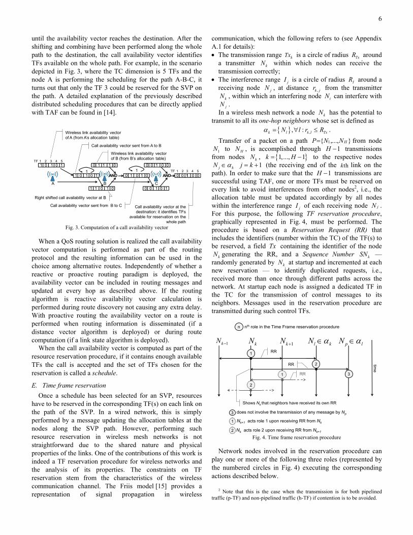
and resource reservations can be performed in a distributed fashion using a data structure called availability vector. The link availability vector can be derived from the allocation table as the TFs that have not yet been reserved for transmission over a wireless channel, i.e. a vector of bits equal to one if the TF is free and zero otherwise. The call availability vector is initialised to the link availability vector of the source and sent along the path selected for the SVP, as shown in the sample scenario depicted in Fig. 3. A node upon receiving the call availability vector cyclically shifts it to the right a number of times equivalent to the forwarding delay (measured in TFs) introduced by the node, which is the delay packets experience from the upstream node output buffer to the considered node output buffer. In the sample scenario represented in Fig. 3 the forwarding delay is assumed to be 1 on each link, i.e., each node right shifts the received call availability vector of 1 position. A bit-by-bit logical AND operation1 is then performed between the resulting call availability vector and the link availability vector of the node. The result is the updated call availability vector to be forwarded to the next node that performs the same operations,
1 In case TFs can be reserved in fractions rather than as a whole, each
element of the availability vector contains a number indicating the amount of capacity available during the TF and a minimum operation is used on each element instead of the AND operation.
6
until the availability vector reaches the destination. After the shifting and combining have been performed along the whole path to the destination, the call availability vector identifies TFs available on the whole path. For example, in the scenario depicted in Fig. 3, where the TC dimension is 5 TFs and the node A is performing the scheduling for the path A-B-C, it turns out that only the TF 3 could be reserved for the SVP on the path. A detailed explanation of the previously described distributed scheduling procedures that can be directly applied with TAF can be found in [14].
12 12
12
12
1 0 1 0 1
1 0 1 0 11
120 1 0 1 01
0 1 1 1 0
121 1 0 1 0
AND
0 0 1 0 1
120 0 1 0 0
AND 120 0 1 0 0
A B C
Wireless link availability vector of A (from A’s allocation table)
Right shifted call availability vector at B
Call availability vector sent from A to B
Wireless link availability vectorof B (from B’s allocation table)
Call availability vector sent from B to C Call availability vector at the destination: it identifies TFs
available for reservation on the whole path
TF 1 2 3 4 5
TF 1 2 3 4 5
Fig. 3. Computation of a call availability vector
When a QoS routing solution is realized the call availability
vector computation is performed as part of the routing protocol and the resulting information can be used in the choice among alternative routes. Independently of whether a reactive or proactive routing paradigm is deployed, the availability vector can be included in routing messages and updated at every hop as described above. If the routing algorithm is reactive availability vector calculation is performed during route discovery not causing any extra delay. With proactive routing the availability vector on a route is performed when routing information is disseminated (if a distance vector algorithm is deployed) or during route computation (if a link state algorithm is deployed).
When the call availability vector is computed as part of the resource reservation procedure, if it contains enough available TFs the call is accepted and the set of TFs chosen for the reservation is called a schedule.
E. Time frame reservation Once a schedule has been selected for an SVP, resources
have to be reserved in the corresponding TF(s) on each link on the path of the SVP. In a wired network, this is simply performed by a message updating the allocation tables at the nodes along the SVP path. However, performing such resource reservation in wireless mesh networks is not straightforward due to the shared nature and physical properties of the links. One of the contributions of this work is indeed a TF reservation procedure for wireless networks and the analysis of its properties. The constraints on TF reservation stem from the characteristics of the wireless communication channel. The Friis model [15] provides a representation of signal propagation in wireless
communication, which the following refers to (see Appendix A.1 for details): • The transmission range kTx is a circle of radius TxR around
a transmitter kN within which nodes can receive the transmission correctly;
• The interference range jI is a circle of radius IR around a receiving node jN , at distance ,k jr from the transmitter
kN , within which an interfering node iN can interfere with jN .
In a wireless mesh network a node kN has the potential to transmit to all its one-hop neighbors whose set is defined as
{ } ,, :k l k l TxN l r Rα = ∀ ≤ . Transfer of a packet on a path 1{ ,..., }HP N N= from node 1N to HN , is accomplished through 1H − transmissions
from nodes kN , { }1,..., 1k H= − to the respective nodes j kN α∈ 1j k= + (the receiving end of the thk link on the
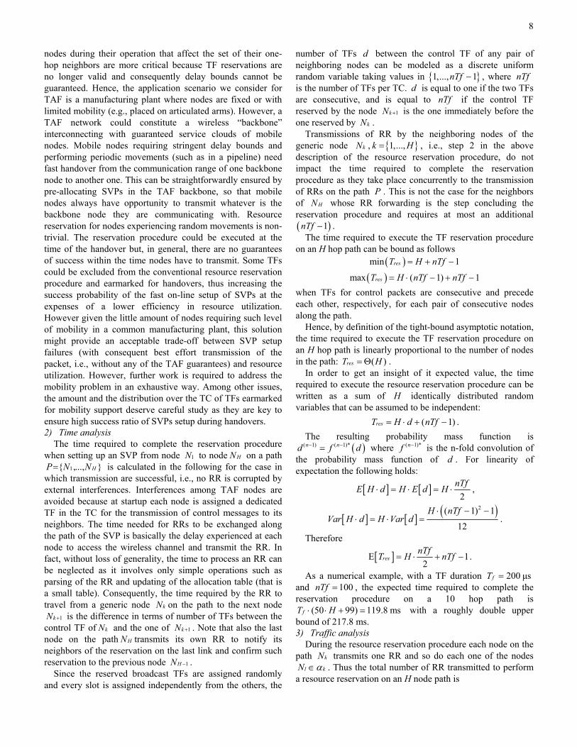
path). In order to make sure that the 1H − transmissions are successful using TAF, one or more TFs must be reserved on every link to avoid interferences from other nodes2, i.e., the allocation table must be updated accordingly by all nodes within the interference range jI of each receiving node jN . For this purpose, the following TF reservation procedure, graphically represented in Fig. 4, must be performed. The procedure is based on a Reservation Request (RR) that includes the identifiers (number within the TC) of the TF(s) to be reserved, a field Tx containing the identifier of the node
kN generating the RR, and a Sequence Number kSN — randomly generated by kN at startup and incremented at each new reservation — to identify duplicated requests, i.e., received more than once through different paths across the network. At startup each node is assigned a dedicated TF in the TC for the transmission of control messages to its neighbors. Messages used in the reservation procedure are transmitted during such control TFs.
does not involve the transmission of any message by Np
kN 1kN + l kN α∈ p lN α∈
2
1
3
n nth role in the Time Frame reservation procedure
1kN −
1 3
time
RR
RR
RR
Shows Nk that neighbors have received its own RR
1 Nk+1 acts role 1 upon receiving RR from Nk
2
2 Nk acts role 2 upon receiving RR from Nk+1 Fig. 4. Time frame reservation procedure
Network nodes involved in the reservation procedure can
play one or more of the following three roles (represented by the numbered circles in Fig. 4) executing the corresponding actions described below.
2 Note that this is the case when the transmission is for both pipelined traffic (p-TF) and non-pipelined traffic (h-TF) if contention is to be avoided.

7
1. kN , upon receiving from 1kN − an RR (not shown in Fig. 4) in a frame whose MAC destination matches its own MAC address and after making sure that it is not a duplicate, updates its allocation table by storing the Tx and kSN fields in the entry corresponding to the TF(s) being reserved for transmission by 1kN − . • If the Tx , and kSN fields of a received RR match the
values already in the relevant entries of the allocation table (the kSN field value of the packet can also be smaller), the packet is a duplicate and discarded by the node.
• If one of the relevant allocation table entries contains a node identifier different from the one in the Tx field, i.e., the TF has been already reserved by a node different from 1kN − , the reservation procedure fails and has to be restarted by the source. It is worth noticing that this situation occurs only if in the quite unlikely event that two nodes attempt at the same time to reserve the same TF(s) for two different SVPs sharing one or more links.
Then kN transmits to 1kN + an RR that includes the identifiers of the receiving TFs (i.e., the ones listed in the RR from 1kN − ) and the forwarding TFs (i.e., the ones kN wants to reserve to forward packets received from 1kN − ). The transmission of the RR by kN is represented in Fig. 4 by the arrows reaching all the nodes in its transmission range l kN α∈ , including 1kN − and 1kN + . To ensure the correct reception of the RR, if kN does not receive an RR corresponding to the given reservation from a number3 of its neighbors l kN α∈ within one TC, it retransmits the RR4. In fact, also 1kN + upon receiving the RR from kN plays role 1, as shown in Fig. 4 by the dashed circle numbered 1 on the timeline of 1kN + . The last node on the path of an SVP or the receiver of an h-TF reservation, broadcasts the RR, i.e., encapsulates it into a frame whose MAC destination address is 0xFFFFFFFFFFFF.
2. Every node 1,l k l kN N Nα +∈ ≠ , i.e., receiving an RR (shown by the arrow from the timeline of kN in Fig. 4) in a frame whose MAC source address matches the Tx field and the MAC destination address is not its own, after making sure that the message is not a duplicate, updates its allocation table and broadcasts the RR to its neighbors. This step ensures that the RR originated by kN reaches all the nodes , :p l l kN l Nα α∈ ∀ ∈ , as shown in Fig. 4 by the arrows from the time line of lN to the ones of kN and pN . Note that kN also plays role 2 when receiving the RR by
1kN + , as represented in Fig. 4 by the circle numbered 2 on the timeline of kN .
3. Every node , :p l l kN l Nα α∈ ∀ ∈ , i.e., receiving an RR in a frame whose MAC source address does not match the Tx field, after making sure the message is not a duplicate, updates its allocation table accordingly without further retransmitting the RR, represented by circle numbered 3 in
3 kN might set a minimum number of received RRs, based on the
estimated cardinality of kα , below which it retransmits its own. 4 Reception of RR by 1kN + is ensured by the IEEE 802.11 acknowledgment
mechanism (not shown in Fig. 4).
Fig. 4. The reservation procedure as described above is initiated by
the ingress node of an SVP sending an RR including only the identifiers of the TF(s) it wants to reserve for packet transmission to the next hop. The reservation procedure can also be initiated by an SVP egress node by transmitting an RR including only the identifiers of the TF(s) it wants to reserve for receiving packets from the previous node. The reservation procedure is also initiated by a node wanting to reserve an h-TF to transmit non-pipelined traffic to another node. 1) Effectiveness
The above described TF reservation procedure is effective — i.e., all the nodes that can cause interference with a transmission are aware of the resources having been reserved for that transmission — if the following two Theorems hold true:
Theorem 1 For any TF m reserved for transmission from node kN to node jN utilizing a TF reservation procedure, reception by node jN will not be disrupted by interference from any other well-behaved network node, i.e., correctly abiding to the reservation procedure and TF access rules.
Theorem 2 For very TF m flagged as not reserved in the allocation table of node iN , a transmission by node iN does not interfere with an existing reservation.
These two theorems can be proven for the TF reservation procedure presented above (see Appendix A.2) on a wireless mesh network satisfying the following constraint: Let • TxG be an undirected weighted graph obtained connecting
two nodes kN and jN ,k j∀ with an edge ,TxG
k je of weight 1 if and only if ,k j Txr R< — TxG represents the graph of the nodes that can communicate with each other directly);
• IG be an undirected graph obtained connecting two nodes iN and jN with an edge ,
IGi je if and only if ,i j Ir R< —
IG represents the graph of the nodes that can cause interference to a transmission between a node kN and jN in the worst case where ,k j Txr R= ;
,, : IGi ji j e∀ ∃ , ,: TxG
k jk e∀ ∃ there must exist a path ,TxG
k iP on the graph TxG between kN and iN such that the total weight
,2GTx
k iPW ≤ . An example of network satisfying this constraint is a
regular grid with fixed distance ( TxR ) between nodes. In general, it is not unlikely that dense wireless mesh networks deployed in practical cases satisfy this constraint.
A TF reservation procedure that features the properties expressed by the above theorems on a wireless mesh network not necessarily satisfying the above constraint can be devised by substituting RRs with binary energy signals. Such a reservation procedure, that is not as simple as the one presented in this paper, will be the subject of future work.
The proposed resource reservation procedure allows TAF to smoothly handle modifications of production lines: whenever nodes have are moved due to the realization of a different production line, the resource reservation procedure assures a fast reconfiguration of the allocated resources, which allows the network to satisfy new traffic requirements. Movements of
8
nodes during their operation that affect the set of their one-hop neighbors are more critical because TF reservations are no longer valid and consequently delay bounds cannot be guaranteed. Hence, the application scenario we consider for TAF is a manufacturing plant where nodes are fixed or with limited mobility (e.g., placed on articulated arms). However, a TAF network could constitute a wireless “backbone” interconnecting with guaranteed service clouds of mobile nodes. Mobile nodes requiring stringent delay bounds and performing periodic movements (such as in a pipeline) need fast handover from the communication range of one backbone node to another one. This can be straightforwardly ensured by pre-allocating SVPs in the TAF backbone, so that mobile nodes always have opportunity to transmit whatever is the backbone node they are communicating with. Resource reservation for nodes experiencing random movements is non-trivial. The reservation procedure could be executed at the time of the handover but, in general, there are no guarantees of success within the time nodes have to transmit. Some TFs could be excluded from the conventional resource reservation procedure and earmarked for handovers, thus increasing the success probability of the fast on-line setup of SVPs at the expenses of a lower efficiency in resource utilization. However given the little amount of nodes requiring such level of mobility in a common manufacturing plant, this solution might provide an acceptable trade-off between SVP setup failures (with consequent best effort transmission of the packet, i.e., without any of the TAF guarantees) and resource utilization. However, further work is required to address the mobility problem in an exhaustive way. Among other issues, the amount and the distribution over the TC of TFs earmarked for mobility support deserve careful study as they are key to ensure high success ratio of SVPs setup during handovers. 2) Time analysis
The time required to complete the reservation procedure when setting up an SVP from node 1N to node HN on a path
1{ ,..., }HP N N= is calculated in the following for the case in which transmission are successful, i.e., no RR is corrupted by external interferences. Interferences among TAF nodes are avoided because at startup each node is assigned a dedicated TF in the TC for the transmission of control messages to its neighbors. The time needed for RRs to be exchanged along the path of the SVP is basically the delay experienced at each node to access the wireless channel and transmit the RR. In fact, without loss of generality, the time to process an RR can be neglected as it involves only simple operations such as parsing of the RR and updating of the allocation table (that is a small table). Consequently, the time required by the RR to travel from a generic node kN on the path to the next node
1kN + is the difference in terms of number of TFs between the control TF of kN and the one of 1kN + . Note that also the last node on the path HN transmits its own RR to notify its neighbors of the reservation on the last link and confirm such reservation to the previous node 1HN − .
Since the reserved broadcast TFs are assigned randomly and every slot is assigned independently from the others, the
number of TFs d between the control TF of any pair of neighboring nodes can be modeled as a discrete uniform random variable taking values in { }1,..., 1nTf − , where nTf is the number of TFs per TC. d is equal to one if the two TFs are consecutive, and is equal to nTf if the control TF reserved by the node 1kN + is the one immediately before the one reserved by kN .
Transmissions of RR by the neighboring nodes of the generic node kN , { }1,...,k H= , i.e., step 2 in the above description of the resource reservation procedure, do not impact the time required to complete the reservation procedure as they take place concurrently to the transmission of RRs on the path P . This is not the case for the neighbors of HN whose RR forwarding is the step concluding the reservation procedure and requires at most an additional ( )1nTf − .
The time required to execute the TF reservation procedure on an H hop path can be bound as follows
( )min 1resT H nTf= + −
( )max ( 1) 1resT H nTf nTf= ⋅ − + − when TFs for control packets are consecutive and precede each other, respectively, for each pair of consecutive nodes along the path.
Hence, by definition of the tight-bound asymptotic notation, the time required to execute the TF reservation procedure on an H hop path is linearly proportional to the number of nodes in the path: ( )resT H= Θ .
In order to get an insight of it expected value, the time required to execute the resource reservation procedure can be written as a sum of H identically distributed random variables that can be assumed to be independent:
( 1)resT H d nTf= ⋅ + − . The resulting probability mass function is
( )( 1) ( 1)*n nd f d− −= where ( 1)*nf − is the n-fold convolution of the probability mass function of d . For linearity of expectation the following holds:
[ ] [ ]2
nTfE H d H E d H⋅ = ⋅ = ⋅ ,
[ ] [ ] ( )2( 1) 1
12
H nTfVar H d H Var d
⋅ − −⋅ = ⋅ = .
Therefore
[ ]E 12
resnTfT H nTf= ⋅ + − .
As a numerical example, with a TF duration 200 μsfT = and 100nTf = , the expected time required to complete the reservation procedure on a 10 hop path is
(50 99) 119.8 msfT H⋅ ⋅ + = with a roughly double upper bound of 217.8 ms. 3) Traffic analysis
During the resource reservation procedure each node on the path kN transmits one RR and so do each one of the nodes
l kN α∈ . Thus the total number of RR transmitted to perform a resource reservation on an H node path is

9
pktH N c H≤ ≤ ⋅ , where ( )[1,.., ]
max 1kk n
c α∈
= + .
Hence, by definition of the tight-bound asymptotic notation, the number of packets exchanged during the presented resource reservation procedure is linearly proportional to the number of nodes on the path H:
( )pktN H= Θ .
In order to get an insight of the expected total number of packets we model the network as a graph whose nodes are randomly placed according to a Poisson Point Process in 2 with intensity β . The resulting expected number of neighbors for a generic node kN is 2
TxRβπ [20], thus 2[ ] (1 )pkt TxE N R Hβ π= + ⋅ ⋅ ⋅ . For example, for a network like
in Fig. 6(B) utilizing the K-function [21] 4.9 05eβ − , and the expected number of neighbors for every node is 6.15 thus
[ ] 7.15pktE N H= ⋅ .
F. IEEE 802.11e Standard and TAF Implementation Since the IEEE 802.11 standards family is the most widely
established among wireless local area network technologies [4], a TAF implementation building on top of current MAC mechanisms enables taking advantage of the economy of scale of IEEE 802.11 components. The basic idea underlying such an implementation is to define TFs that can include transmission of packets and their respective acknowledgements sent by receiving nodes.
IEEE 802.11 standards offer a wide range of solutions to handle multiple access to a wireless link. The Enhanced Distributed Coordinated Access (EDCA), specified within IEEE 802.11e to include mechanisms for traffic prioritization, can be utilized as a Medium Access Control (MAC) solution in wireless multi-hop networks given its non-centralized nature. EDCA offers four priority levels, each utilizing different parameters in accessing the channel. Before trying accessing the channel each traffic class waits for a different medium idle period whose duration equals the Advanced Inter Frame Space (AIFS[n]), where n is the class number; the higher the class priority, the shorter the corresponding AIFS. Furthermore, after a collision each traffic class waits for a random number of slot times (of duration 10 μs) drawn from the range values of the class-specific Contention Window [ min
nCW , maxnCW ]; the higher the class priority, the lower the
CW values. Within the EDCA protocol, IEEE 802.11e also defines the Transmission Opportunities (TXOPs), which are continuous time slots that a node can use exclusively to transmit one or more packets. Since the TXOP time is exclusive, during TXOPs nodes can begin the transmission of a packet without waiting for their AIFS, i.e., right after a Short Inter Frame Space (SIFS), that is the minimum time required by a node to switch from transmission to reception mode and vice versa, from the beginning of the TXOP. Subsequent packets within a transmission opportunity are spaced by at least a SIFS.
Since there is no contention during a reserved TF, TAF nodes utilize the SIFS period, as during an IEEE 802.11e TXOP: whenever a TF begins according to the deployed CTR, a node for which the TF is reserved can start transmitting after a SIFS period. The receiving node waits, in its turn, the SIFS
period and then can send the corresponding ACK. Since TAF only requires simple modifications to the firmware of commercially available 802.11 cards, it can be easily implemented, brought to the market in a short time, and leverage on the economy of scale of IEEE 802.11 components to ensure the low cost of interfaces.
G. End-to-end delay analysis After properly reserving TFs along the path from source to
destination, packets are transmitted without collision on each wireless link. Furthermore, thanks to the pipeline-like forwarding through the multi-hop path, they can reach the destination with predetermined low latency as queuing delay at intermediate hops is minimized. In particular, the delay experienced by packets at node iN is deterministic and given by the forwarding delay iτ at the node. Hence the end-to-end delay D experienced by a packet over a path
1{ ,..., }HP N N= is 1
1 ( 1)2H
i H H HiD W Dpτ−− −== + +∑ , (1)
where Wi is the extra time node iN waits when transmitting a packet in order to ensure compliance with the adopted wireless standard5 (e.g., SIFSiW = in our IEEE 802.11-based scenario), and ( 1)i iDp − is the propagation delay between two subsequent nodes 1iN − and iN .
H. Tolerance to external interferences Section E presented and assessed a TF reservation
procedure that virtually rules out interferences by other TAF nodes, i.e., internal interferences. However, communication among TAF nodes can still be affected external interferences, i.e., caused by TAF-unaware devices, such as manufacturing machinery and transmitters of other radio communication systems possibly deployed within a production plant. As previously mentioned, the high Bit Error Rate (BER) typically tainting wireless channels due to the presence of interferences can be significantly limited in wireless multi-hop networks. In fact, intermediate nodes between distant wireless terminals can forward packets on shorter (and hence more reliable and stable) wireless links [5]. However, given the sensitivity of industrial applications to packet losses, external interferences have to be given due consideration.
The most significant solutions proposed so far in the context of various wireless technologies to cope with interferences can be adopted also in the context of TAF. In particular, Forward Error Correction (FEC) coding [16] can be added to packets so that the receiver can detect and correct errors due to interferences (if not too many), thus avoiding packet retransmission. In addition, packet duplication mechanisms (performed for example according to the method proposed in [17]) can be deployed by reserving additional TFs for each traffic flow, i.e., trading interference tolerance for network utilization. These methods have to be used jointly with an Automatic Repeat reQuest (ARQ) technique, so that packets can be retransmitted when “negative-acknowledged”
5 Wi could also include a guard time band, which is necessary to overcome synchronization inaccuracies of nodes. See Section IV for more details.

10
by the receiver. TAF supports ARQ solutions as each packet transmission is acknowledged (in compliance to the IEEE 802.11 specification). In TAF, retransmissions can be handled in different ways. In particular, a packet can be retransmitted (i) during the next TF allocated to the flow it belongs to, (ii) at high priority according to the standard IEEE 802.11e specification as soon as the channel is free (i.e., during the first empty TF), (iii) at high priority during h-TFs specifically earmarked for packet retransmissions. Clearly, the first solution ensures delivery with bounded delays also to retransmitted packets, but requires additional TFs being reserved to each flow in order to (a) reduce the time a packet waits at a node before being retransmitted, and (b) avoid delaying subsequent packets belonging to the same flow. The second solution, that leverages on the standard IEEE 802.11e transmission mechanisms, provides performances, in terms of delay and service disruption in case of interferences, comparable to the ones achievable with the IEEE 802.11e protocol. The third solution is a trade-off between the other approaches: some TFs are reserved for retransmissions, but are shared among several flows which can contend for them in the case of packet retransmissions. The three approaches could also be combined in hybrid solutions: for example, some additional TFs can be reserved by each flow for the first n retransmissions, and then the remaining retransmissions are handled according to the IEEE 802.11e standard, until the deadline for packets expire.
In addition, nodes can take advantage of the intrinsic spatial diversity [18] that wireless multi-hop networks based on mesh topologies provide thanks to path redundancy. As mentioned in Section III.C, routing protocols are instrumental in this by providing necessary support to exploit such path redundancy.. For example, Ad-hoc On-demand Multipath Distance Vector routing (AOMDV) [24] enables more than one path (possibly link disjoint or node disjoint) to be chosen for a destination. In case of problems with a link, e.g., due to interferences, on one path, a new one, not sharing any link and/or node with the faulty path, is readily available. For transmissions needing hard-QoS it is possible to allocate resources on multiple paths and even possibly transmit duplicate packets along two or more paths.
Finally, spread-spectrum transmission solutions, implemented in most of the wireless standards to ensure low BER, can be used to cope with interferences also when TAF is deployed.
The above description shows how TAF can deal with interferences. Although some guidelines are provided about some possible specific solutions, an in depth analysis is required to characterize the efficiency and achievable interference tolerance of each approach in terms of network utilization, loss, delay experienced by packets corrupted by interference, and tradeoffs thereof. For example, the definition of proper schemes for the distribution of TFs reserved for retransmission within the TC is a key point to guarantee low delays to packets damaged due to interferences. The outcome of this study is a framework defining how the different
solutions can be alternatively adopted depending on the specific deployment scenarios and the type of service required by each flow. Such comprehensive analytical and validation work is outside the scope of this paper and is therefore left to future publications.
IV. SYNCHRONIZATION In order to implement the described CTR-based TDMA
with pipeline forwarding, TAF needs clocks at all network nodes to be kept accurately synchronized. In fact, an error on clock synchronization results in a misalignment on the beginning of TFs which may cause collisions and, consequently, packet losses. It is worth noticing that synchronization is already deployed in IEEE 802.11 and other wireless network standards for various purposes, such as maximizing network throughput and coordinating sleep mode intervals to reduce power consumption. However, strict synchronization requirements possibly result in the need for very accurate clocks and/or sophisticated synchronization protocols, which would increase the cost of network interfaces and have the potential to limit the ease of deployment of TAF. Clock misalignment can be effectively handled in TAF with the introduction of a guard time band, during which no transmission occurs, at the beginning of each TF, as shown in Fig. 5. In particular, the following can be stated (see Appendix A.3 for its proof):
Theorem 3 Given a TAF network where (i) all nodes utilize the collision free reservation procedure presented in Section III.E and (ii) the maximum synchronization error among network nodes is tERRΔ , an additional guard time band tB ERR= Δ at the beginning each TF is sufficient to avoid collisions due to synchronization errors.
TF 1 TF 2
Guard band SIFS SIFSData packet Ack
…TF 3
TC
fT
Fig. 5. TF transmission times
The knowledge of an upper bound for the synchronization
error tERRΔ is necessary in order to evaluate the duration of the band B. Such value depends on the specific node synchronization solution that is adopted in the network. The IEEE 802.11 standard specifies the Timing Synchronization Function (TSF) through which nodes do not adjust their clock frequencies, but simply maintain a local time counter that is periodically adjusted in order to follow the fastest clock in the network. In detail, a node mN reads the timestamp value TS contained in received beacon frames, compares it with its

11
timer value mt , and then updates the local time counter to the beacon time only if mTS t> . The maximum synchronization error achievable with TSF depends on the number of interfering nodes and can become very large when the number of nodes in the same transmission range increases [19]. In a multi-hop scenario, since the synchronization information must cross multiple hops from a faster node to a slower one,
tERRΔ can be significant, possibly exceeding 250 μs for a network of 100 nodes and few hops [19].
The Multi-hop Adaptive Time Synchronization Function (MATSF) [19] has been proposed to achieve synchronization with good accuracy among nodes in IEEE 802.11 networks. By defining a more complex and accurate time adjustment procedure, MATSF guarantees the convergence of node clocks to a unique network time (the time of the fastest clock) eliminating synchronization errors due to drifts. In [19] MATSF has been tested to work for a network of 300 randomly placed nodes. In these experiments, after 5000 beacon periods the maximum offset among the nodes is reported steadily below 30 μs. There is a tradeoff between the maximum offset and the time needed to achieve it. In [19] 5000 beacon periods have been chosen as a reasonable synchronization delay (500 seconds in the considered simulation scenarios); waiting a higher number of beacon periods enables MATSF to further reduce the maximum offset. On a larger network (i.e., including more than 300 nodes) more beacon periods are required at the network startup to achieve the same maximum offset of 30 μs. Hence, according to Theorem 3 and the results in [19], a guard time band = 30 μsB is sufficient to ensure TAF to properly operate in a 300 node network where MATSF is deployed to provide synchronization. It is worth noticing that MATFS is completely transparent to our solutions because it does not utilize additional ad-hoc packets: like the standard solution TSF, MATFS is based on the timestamp value contained in the beacon frames periodically exchanged by IEEE 802.11 terminals.
The accuracy achievable by MATFS can be improved when TAF is deployed since TFs can be reserved for beacon frame transmission to avoid them to collide, which eliminates the uncertainty on their actual transmission time.
V. SIMULATION EXPERIMENTS The performance of the proposed solution in supporting
real-time industrial communications is assessed in this section through simulation and compared to the case in which standard IEEE 802.11 protocols are used. The purpose of this section is to validate the analysis presented in the previous section, i.e., to show how TAF can provide a congestion free service in a wireless multi-hop network. Consequently, although generally very important issues, mobility of nodes and effects of external interferences are not considered here and left to further work because they are outside the scope of this paper.
A. Simulation environment Simulations have been carried out using the publicly
available network simulator ns-2 (version 2.28), also including an IEEE 802.11e EDCA implementation. A module implementing TAF has been developed in the context of this work. The allocation protocol presented in Section III.E has been emulated off line to produce a TF reservation that has been statically configured on the path of each flow when starting the simulation.
B. Simulation scenario Two multi-hop scenarios have been simulated, both
satisfying the constraints defined in Section III.E under which the presented reservation procedure features the properties expressed by the related theorems. Both are industrial networks with nodes transmitting towards a monitoring station and a control station transmitting towards the nodes. The second scenario also includes background traffic (handled in a best-effort fashion). The first scenario is a linear chain of ten nodes, while the second one is a thirty node network in an area of 1000x1000 meters. In both scenarios the distance between nodes is about 100 meters and their transmission range is 100 meters with an interference range of 200 meters. A node has two to four nodes within its transmission range in the first scenario, and three to four in the second one. The Dijkstra algorithm is used to pre-calculate routes to all destinations to then statically fill out the routing tables of the nodes. IEEE 802.11g is utilized in all simulations. The maximum fixed data rate is 12 Mbps (there is no Auto-fall-back) which has been chosen to simulate data rates in a typical industrial scenario with high interference level; the basic data rate is 6 Mbps. A free-space propagation model has been utilized. The TC duration is 20 ms with 100 TFs per TC; a guard band of 30 μs is used in each TF in order to enable proper operation with MATSF synchronization. The forwarding delay is fixed to 1 TF for each node, i.e.,
200 μs, i iτ τ= = ∀ . The tenth node of the chain in the first scenario (network A
in Fig. 6) and the node in the upper right corner of the simulation area in the second scenario (network B in Fig. 6) act as monitoring stations; the upper left node in the second scenario is a control station. Most of the traffic, both real-time and best-effort, is directed towards the monitoring stations. In the first scenario the first node is the only traffic source, while in the second one the fifteen nodes in the lower part of the simulated area transmit towards the monitoring station on the right; furthermore, the control station (top left) transmits to four stations and there are three best-effort background traffic flows (Fig. 6). Both real-time and best-effort flows are Constant Bit Rate (CBR) 20 kbps packet flows. While best-effort traffic is transmitted during TFs allocated between adjacent nodes, real-time flows are pipeline forwarded with a TF allocation from source to destination.

12
(A)
(B)Wireless
node
Real-time flow tomonitoring station
Best-effortflow
Monitoring/Control station
ObservedReal-time flow
Real-time flowfrom control station
(A)
(B)Wireless
node
Real-time flow tomonitoring station
Best-effortflow
Monitoring/Control station
ObservedReal-time flow
Real-time flowfrom control station
Fig. 6. Network configuration: (A) ten node network,
(B) thirty node network
C. Results End-to-end delay and throughput obtained with TAF,
IEEE 802.11 DCF, and IEEE 802.11e EDCA are compared. In the ten node network the 22 real-time flows are activated in sequence, resulting in a maximum real-time traffic of 440 Kbps fully directed to the last node of the chain representing a monitoring station. Fig. 7 shows how TAF can guarantee very low delay to real-time transmissions, i.e., about 1.7 ms, which is compliant with the analytical value given by (1) — consider that the sum of the guard time band size, the SIFS period duration, and the per-hop propagation delay is about 100 μs. The simulation results also confirm that IEEE 802.11 DCF and IEEE 802.11e EDCA perform poorly in terms of end-to-end delay (the average end-to-end delay being bigger than 200 ms in certain traffic conditions), as expected and already showed in [7]. Fig. 8 shows that the throughput achieved by TAF is stable and equal to the input data rate, thus validating the interference avoidance properties of the proposed solution (i.e., of the combination of TAF and the resource reservation protocol).
0.001
0.01
0.1
1
10
100
0 50 100 150 200 250 300 350 400 450
End
-to-e
nd d
elay
[sec
onds
], lo
gsca
le
Total input traffic [Kbps]
End-to-end delay, ten node network
TAF, end-to-end delay, min,average,maxIEEE 802.11e end-to-end delay, min,average,maxIEEE 802.11 end-to-end delay, min,average,max
Fig. 7. End-to-end delay in a ten node network
In the second simulation scenario (the thirty node network
in Fig. 6), the total traffic generated by the various sources is 440 Kbps: 300 Kbps monitoring traffic (blue and yellow lines), 80 Kbps control traffic (red lines), and 60 Kbps
background traffic (purple dashed lines). Due to space limitation and without loss of significance, the end-to-end delay experienced by packets of a single flow (yellow line in Fig. 6) is plotted in Fig. 9. Such delay is constant and compliant with the analytical value in Section III.G when TAF is deployed. It is worth noticing how, unlike IEEE 802.11 standards, TAF performance is independent of the network complexity. In the thirty node network, where interferences between nodes are more likely to occur, the end-to-end delay provided by IEEE standard MACs is bigger than in the ten node one, even though the path length is shorter. On the contrary, in TAF the end-to-end delay is deterministically bound to the path length, as given by (1).
0
100
200
300
400
500
600
0 50 100 150 200 250 300 350 400 450
Thro
ughp
ut [K
bps]
Total input traffic [Kbps]
Throughput, ten node network
TAF, throughputIEEE 802.11e throughputIEEE 802.11 throughput
Fig. 8. Throughput in a ten node network
VI. CONCLUSIONS AND FUTURE WORK This paper presents the Time-driven Access and
Forwarding (TAF) solution for guaranteeing deterministic end-to-end delay in industrial wireless multi-hop networks. The paper also proposes a low complexity reservation procedure, proves its properties when it is be deployed on a network satisfying some fairly common topological constraints, and provides simulation results that validate the presented proofs.
Although current results are promising with respect to the possibility of ensuring the deterministic service, in terms of end-to-end delay, required in industrial networks, further work is needed to study the efficiency of the solution in terms of resource utilization and how to maximize it. Specifically, future work will focus on an analytical model of the achievable throughput and channel allocation algorithms maximizing spatial reuse of the wireless channel and bandwidth utilization.
Furthermore, routing protocols as well as solutions to efficiently deal with external interference and mobility specifically designed for networks in which TAF is deployed will be studied and validated.
Finally, an important topic for future study is a reservation procedure to ensure on general topology networks properties similar to those proven for the one presented in this work.

13
0.001
0.01
0.1
1
10
100
50 100 150 200 250 300 350 400
End
-to-e
nd d
elay
[sec
onds
], lo
gsca
le
Input traffic [Kbps]
End-to-end delay, thirty node network
TAF, end-to-end delay, min,average,maxIEEE 802.11e end-to-end delay, min,average,maxIEEE 802.11 end-to-end delay, min,average,max
Fig. 9. End-to-end delay in thirty node network
APPENDIX A
A.1 Physical channel model The Friis propagation model [15] describes a physical
communication channel as follows: 2
,
14
Rx Tx Tx RxTx Rx
P P G Gr δ
λπ
⎛ ⎞⎛ ⎞= ⎜ ⎟⎜ ⎟⎝ ⎠ ⎝ ⎠
where RxP is the signal power at the receiver, TxP is the transmission power of the transmitter, TxG and RxG are the antenna gains, λ is the transmission wavelength, ,Tx Rxr is the distance between the transmitter and the receiver, and δ is the attenuation coefficient ranging from 2 to 5 depending on the transmission medium. Considering a transmission from node
kN to node jN , an interfering node iN , and assuming the noise negligible, the Signal and Interference Noise Ratio (SINR) at jN is
2
, ,, 2
,
,
14
SINR1
4
Tx Tx Rxk j i ji
k jk j
Tx Tx Rxi j
P G Gr r
rP G G
r
δ δ
δ
δ
λπ
λπ
⎛ ⎞⎛ ⎞⎜ ⎟ ⎜ ⎟⎝ ⎠ ⎝ ⎠= =
⎛ ⎞⎛ ⎞⎜ ⎟ ⎜ ⎟⎝ ⎠ ⎝ ⎠
The receiver is able to decode the transmission if SINR is greater than a reception threshold ThR , thus jN can receive the transmission correctly if
, ,k j Thi jr r Rδ≤ . (2)
In this paper it is considered 2ThRδ = , which is a reasonable value for IEEE 802.11 networks.
A node can sense a transmission if SINR ThCs> where ThCs is the carrier sense threshold. The receiver is able to
sense but not to decode the transmission if SINRTh ThCs R≤ < . It is reasonable to assume ThR and ThCs to be fixed for the whole network.
The transmission range iTx is a circle of radius 2 1
4Tx Tx Tx Rx
ThR P G G
Rδ
λπ
⎛ ⎞ ⎛ ⎞= ⎜ ⎟ ⎜ ⎟⎝ ⎠ ⎝ ⎠
around a transmitter iN within which nodes can receive the transmission correctly. The carrier sense range iCs around a receiver iN is defined as the circle of radius
2 14
Cs Tx Tx RxTh
R P G GCs
δλπ
⎛ ⎞ ⎛ ⎞= ⎜ ⎟ ⎜ ⎟⎝ ⎠ ⎝ ⎠
within which the receiver can sense the transmission. The interference range iI around a receiving node jN , given the distance ,k jr from the transmitter kN to the receiver jN , is a circle of radius
,I Thk jR r Rδ= within which an interfering node iN can interfere with jN .
The one-hop neighbor set of a node kN is defined as { } ,, :k l k l TxN l r Rα = ∀ ≤ ,
while the set of nodes { }mN that cannot decode the transmission from the node kN correctly suffering interference from kN in the worst case scenario (in which
mN is receiving a transmission from the node kN with ,k m Txr R= and I Tx ThR R Rδ= ) is defined as
{ } ,, :k m Tx k m IN m R r Rβ = ∀ < ≤ .
k k kδ α β= ∪ is the set of all the nodes that can suffer interference from the node kN .
A.2 Proof of Reservation Procedure Properties Theorem 1 For any TF m reserved for transmission from
node kN to node jN utilizing the TF reservation procedure, reception by node jN will not be disrupted by interference from any other well-behaved network node.
Proof 1. The set of nodes informed of the new transmission from kN to jN , i.e., that will not transmit during TF m, is
t k j l bρ α α α α= ∪ ∪ ∪ . Every node in the network set
{ } ,'
,
:,
:
k f ThTxt f g
j g ThTx
f r R RN N
g r R R
δ
δρ
⎧∀ ≤⎪= ∪ ⎨∀ ≤⎪⎩
(3)
corresponds in the graph IG to a vertex of the edge ,GIk fe or of
the edge ,GIj ge , thus by definition of IG there must exist a path
,GTx
k fP and a path ,GTxj gP of weight 2W ≤ in the graph TxG .
This means that the nodes 'fN and 'gN that are ending vertexes of paths , '
GTxk fP and , '
GTxj gP with weight 1W = are in
the transmission range of kN or of jN and thus they belong to k jα α∪ by the definition of kα and jα . The nodes ''fN and ''gN that are vertex of paths { }, '' , , '',G G GTx Tx Tx
k f k l l fP e e= and { }, '' , , '',G G GTx Tx Tx
j g j l l gP e e= with weight 2W = , where lN is in the transmission range of kα or jα (thus { }l k jN α α∈ ∪ by definition of kα and jα ), are in transmission range of lN thus { }'' '',f g l bN N α α∈ ∪ by definition of lα and bα , consequently 't tρ ρ⊆ .
Every node jN is able to decode the transmission if ,SINR i
k j is greater than ThR thus to prove the theorem 1, (2) must be valid : ii N∀ is transmitting during the TF m. Considering a transmitting node iN , and the worst case for the validity of (2): , ,max( )i j k j thr r Rδ> ⋅ , substituting
( ),max k j Txr R= otherwise kN and jN could not communicate with each other, and 2ThRδ = , , 2i j Txr R> for

14
(2) to hold; for every node t tN ρ∈ informed of the transmission from kN to jN and that will not interfere with it, ,t j ThTxr R Rδ≤ , since a transmitting node i tN ρ∉ ,
, 2i j Txr R> . □
Theorem 2 For every TF m flagged as not reserved in the allocation table of node iN , a transmission by node iN does not interfere with an existing reservation.
Proof 2. If node iN has the TF m flagged as not reserved, while kN has reserved the TF for transmission to jN , then
i tN ρ∉ (from Proof 1) for any receiving node jN . Hence, , 2i j Txr R> (4) for any receiving node jN . According to (2), iN can transmit during TF m without interfering with a transmission from kN to jN if ,
,i j
k jth
rrRδ
≤ . (5)
Considering the worst case for (5), ( ), ,mink j i j thr r Rδ≤ , substituting ( ),min i jr from (4), with 2ThRδ = , then must be
,k j Txr R≤ that is always true otherwise kN and jN could not communicate with each other. □
A.3 Proof of Guard Time Band theorem Theorem 3 Given a TAF network where (i) all nodes utilize
the collision free reservation procedure presented in Section III.E and (ii) the maximum synchronization error among network nodes is tERRΔ , an additional guard time band
tB ERR= Δ at the beginning each TF is sufficient to avoid, collisions due to synchronization errors.
Proof Let’s consider (i) a node kN with a reservation for a TF m,
(ii) an ongoing transmission of a packet in TF m from kN to a receiver jN , (iii) a node iN in the interference range kI of
kN , and (iv) a node tN in the interference range jI of jN . By definition, all of them utilize an additional guard time band B at the beginning of every TF. Thus, if ,x mt is the time at which TF m begins at the generic node xN (referred to the local timer of xN ), transmissions at xN starts at the time
, , SIFSbx m x mt t B= + + and finish by the time , 1x mt + .
Concerning the end of transmissions at nodes, we consider the worst case scenario where the entire TF is engaged by transmissions, i.e., it is valid the equation , , 1
ex m x mt t += , where
,ex mt is the time at which transmissions for TF m end at the
generic node xN (referred to the local timer of xN ). In order for kN transmission towards jN to be successful, iN and tN must not cause interference with kN and jN , respectively. In the following we show how the guard time band tB ERR= Δ can avoid interference between iN and kN . Equivalent statements can be applied to prove no interferences occur between tN and jN . Hence, this case is omitted for the sake of readability. Nodes outside the interference range of
kN cannot cause collisions with kN by definition. On the contrary, iN and kN can collide if iN has to transmit in TF
( )1m − or iN has to transmit in TF ( )1m + . The eventual collision can be caused by an overlapping of (i) the end of iN transmission in ( )1m − with the beginning of the kN transmission in TF m , or (ii) the end of kN transmission in TF m with the beginning of iN transmission in ( 1)m + . Regarding the first possibility, the worst case scenario to consider consists in a synchronization error that leads iN to be tERRΔ late with respect to kN . In this case, necessary and sufficient condition that guarantees no interferences (i.e., collisions) occur is that the time at which transmissions for TF m at kN are scheduled ( ,
bk mt ) follows at least of a time SIFS
the instant at which transmissions for TF 1m − at iN end ( , 1
ei mt − ), i.e.,
, 1, SIFSb ei mk mt t −≥ + .
By imposing worst case conditions ,, 1e
i mi mt t− = and , ,i m k m tt t ERR= + Δ , we can derive
, ,SIFS SIFSk m k m tt B t ERR+ + ≥ + + Δ , which leads to tB ERR≥ Δ .
This ensures that no collisions occur and that transmissions of kN and iN are spaced by SIFS. The same result can be obtained for the case of possible collisions at the end of TF m by inverting kN with iN rules and utilizing 1m + instead of m . □
REFERENCES [1] F. D. Pellegrini, D. Miorandi, S. Vitturi, and A. Zanella, “On the use of
wireless networks at low level of factory automation systems,” IEEE Trans. Ind. Informat., vol. 2, no. 2, pp. 129-143, May 2006.
[2] J. Haehniche, L. Rauchhaupt, “Radio communication in automation systems: the R-fieldbus approach,” Proc. 2000 IEEE Int. Workshop Factory Communication Systems (WFCS), Porto (Portugal), Sep. 2000.
[3] R. Zurawski, “From wireline to wireless networks and technologies,” IEEE Trans. Ind. Informat., vol. 3, no. 2, pp. 93-94, May 2007
[4] A. Willig, “Recent and emerging topics in wireless industrial communications: a selection,” IEEE Trans. Ind. Informat., vol. 4, no. 2, pp. 102-124, May 2008.
[5] H. L. Goh, K. K. Tan, S. Huang, C. W. de Silva, “Development of Bluewave: A wireless protocol for industrial automation,” IEEE Trans. Ind. Informat., vol. 2, no. 4, pp.221-230, Nov. 2006.
[6] N Pogkas, G. E. Karastergios, C. P. Antonopoulos, S. Koubias, G. Papadopoulos, “Architecture design and implementation of an ad-hoc network for disaster relief operations,” IEEE Trans. Ind. Informat., vol. 3, no. 1, pp. 63-72, Feb. 2007.
[7] G. Cena, I. Cibrario Bertolotti, A. Valenzano, C.Zunino, “Evaluation of response times in industrial WLANs,” IEEE Trans. Ind. Informat., vol. 3, no. 3, pp. 191-201, Aug. 2007.
[8] Time-Triggered Protocol TTP/C—High Level Specification Document. TTTech Computertechnik AG, Jul. 2002.
[9] FlexRay Communications System Protocol Specification Version 2.1, FlexRay Consortium, May 2005.
[10] G. Scheible, D. Dzung, J. Endresen, and J.-E. Frey, “Unplugged but connected—Design and implementation of a truly wireless real-time sensor/actuator interface,” IEEE Ind. Electron. Mag., vol. 1, no. 2, pp. 25–34, summer 2007.
[11] T.Yakoh, “Synchronous Time Division Internet for Time-Critical Communication Services,“ EUROMICRO International Workshop on Real-Time LANs in the Internet Age, Vienna (Austria), Jun. 2002.
[12] K. Ueda, T. Yakoh, “Development of time division switching hub for synchronous TDMA,” Proc. 2004 IEEE Int. Workshop Factory Communication Systems (WFCS), Vienna (Austria), Sep.2004.

15
[13] C-S. Li, Y. Ofek, A. Segall, K. Sohraby, “Pseudo-Isochronous Cell Forwarding,“ Computer Networks and ISDN Systems, vol.30, no.24, pp. 2359-2372, Dec. 1998.
[14] M. Baldi, Y. Ofek, "Blocking Probability with Time-driven Priority Scheduling," SCS Symposium on Performance Evaluation of Computer and Telecommunication Systems (SPECTS 2000), Vancouver, BC, Canada, July 2000.
[15] H.T.Friis, “A note on a simple transmission formula,” in Proc. IRE, 34, 1946, vol. 34, pp. 254-256
[16] S. Lin, D. J. Costello, “Error Control Coding,” second edition, Prentice-Hall, Englewood Cliffs, NJ 2004.
[17] A. Annamalai, V. K. Bhargava, “Analysis and optimization of adaptive multicopy transmission ARQ protocols for time-varying channels,” IEEE Trans. Commun., vol. 46, no. 10, pp. 1356-1368, Oct. 1998.
[18] S. N. Diggavi, N. Al-DHahir, A. Stamoulis, A. R. Calderbank, “Great Expectations: The Value of Spatial Diversity in Wireless Networks,” Proc. of the IEEE, vol. 92, no. 2, pp. 219–270, Feb. 2004.
[19] D. Zhou, Lai T.H., “An Accurate and Scalable Clock Synchronization Protocol for IEEE 802.11-based multihop ad hoc networks” IEEE Trans. Parallel and Distrib. Syst., vol. 18, no. 12.
[20] B.D. Ripley, “The second order analysis of stationary point processes,” Journal of Applied Probability, vol. 13, pp. 255-266, 1976.
[21] B.D. Ripley, “Modeling spatial patterns (with discussion),” Journal of the Royal Statistical Society, series B, 39, pp. 172–212, 1977.
[22] IEEE, “Draft amendment: ESS mesh networking,” IEEE P802.11s Draft 1.00, November 2006.
[23] Y. Zhang, T.A. Gulliver, “Quality of Service for Ad hoc On-demand. Distance Vector Routing”, Proc. 2005 IEEE Int. Conf. Wireless And Mobile Computing, Networking And Communications, Aug. 2005.
[24] K. Mahesh Marina, Samir R. Das, “Ad hoc on-demand multipath distance vector routing,” ACM SIGMOBILE Mobile Computing and Communications Review, vol. 6 no.3, Jul. 2002.
Related Documents