Proceedings of the International Association for Shell and Spatial Structures (IASS) Symposium 2013 „BEYOND THE LIMITS OF MAN” 23-27 September, Wroclaw University of Technology, Poland J.B. Obrębski and R. Tarczewski (eds.) 1 Timber Post-formed Gridshell: Digital Form-finding / drawing and building tool Sergio Pone 1 , Sofia Colabella 2 , Bernardino D'Amico 3 , Andrea Fiore 4 , Daniele Lancia 5 , Bianca Parenti 6 1 Professor, Department of Architecture – Federico II University, Naples, Italy, [email protected] 2 PhD, Lecturer, Department of Architecture – Federico II University, Naples, Italy, [email protected] 3 PhD student, Centre for Timber Engineering - Edinburgh Napier University, Edinburgh, UK, [email protected] 4 Architect, Cmmkm Architettura e Design, Naples, Italy, [email protected] 5 Architect, Cmmkm Architettura e Design, Naples, Italy, [email protected] 6 PhD, Architect, Cmmkm Architettura e Design, Naples, Italy, [email protected] Summary: This research deals with design, structural analysis and construction of timber post-formed gridshells. Starting from the scale modelling experience, from 1:20 to 1:1 scale, a digital form-finding strategy was early developed with a Building Process Finite Element (FEA) simulation (GBP-FEAs), with which a real scale experimental structure was designed (and built). Then in a further experimentation building the digital form finding was performed with aid of a graphical algorithm editor (Gfft – Gridshell form finding tool), that uses generative algorithms. At present time both strategies are used together: with the Gfft a “correct” form – and the correspondent flat square mesh - is searched, structural analyzed and improved; then GBP-FEAs finding out the resulting stresses ratio at every deformation stage. The next goal to achieve is the development of an integrated software to design a “correct” gridshell without any knowledge of FEA or graphic algorithms software's. Keywords: timber post-formed gridshell, digital form-finding, form-improvement, generative tools, free form construction 1. INTRODUCTION Our research on timber post-formed gridshell, at present time, can be separated in three stages: 1. Analyze and deepening of post-formed Gridshell typology in which the smartness of form resistance could be combined with the use of small dimension wooden products also derived from coppice. The request of these products, in Italy, in the last 50 years heavily decrease causing the recession of forest industry with huge loss for the woodland heritage and for the society which lied hits economy on wood cutting and manufacturing. Our intention was deepening gridshell construction method to contribute to the growth of use of locally sourced materials and to the growth of local trades creating a new market for wood. We still try to follow what Frei Otto explained: using minimum amounts of material to reduce environmental impacts within a wider idea of social and environmental sustainability. 2. The definition of a Timber post-formed Gridshell designing protocol that keeps together the reasons of architectural design, structural behaviour, drawing and worksite organization, coexisting in a unique design effort, could define a system of necessary forms that qualifies the design thinking through construction and structure and vice versa. This research stage, still related to a scale modelling form-finding through a 1:1 scale models, verified [confirmed] - step by step - up to what point the expressive freedom of gridshell is two-way linked to their structural behaviour and building procedures, and how much form and structure are weaved together to become a resistant form. The scale-model approach to define form resistant shapes (Hook's law, Galileo, Isler, Otto, Nervi, etc.) has been tested as well as the forming steps of digital simulations, to assess the stress of each lath during the assembly. 3. When the acquisition stage of the essential knowledge needed to the construction was enhanced, the research was directed toward the acquiring of new digital tools able to replace entirely the scale-model approach. The main feature of this second research stage is to be deeply linked to the construction’s knowledge previously earned: each tool aspect is gathered from the technological awareness of the construction, of which the entire tool is an emulator. The practise, gained working on site, introduces in effect a number of restrictions and constrains that has to be followed and reproduced in the digital protocol. In addition a structural behaviour cluster must be attached in order to give, right from the first design steps, a rough feedback about gridshell structural performance in order to avoid “wrong” shapes where stress values are too high, with a low overall stiffness, or more generally to find a form which “mainly” works like a shell-membrane rather a shell-plate. Is for that reason that the tool must be supplied with wood mechanical properties, resistant sections, starting flat square mesh spacing and sides to constrain. When is reached a form that satisfies the best architectural, structural and constructive needs, the real structural analysis can take place. As a consequence of these tests (dead weight, permanent and live loads) until now there wasn’t any need to alter the tool obtained shape, as a good validation to the analysis protocol provided in the tool. Fig. 1. Five of nine gridshells designed and build by the research group in the city of (from the top): Ostuni 2007, Lecce 2010, Lecce 2010, Napoli 2012, Selinunte 2012 - Italy.

Welcome message from author
This document is posted to help you gain knowledge. Please leave a comment to let me know what you think about it! Share it to your friends and learn new things together.
Transcript
Proceedings of the International Association for
Shell and Spatial Structures (IASS) Symposium 2013
„BEYOND THE LIMITS OF MAN”
23-27 September, Wroclaw University of Technology, Poland
J.B. Obrębski and R. Tarczewski (eds.)
1
Timber Post-formed Gridshell: Digital Form-finding / drawing and building tool
Sergio Pone1, Sofia Colabella
2, Bernardino D'Amico
3, Andrea Fiore
4, Daniele Lancia
5, Bianca Parenti
6
1 Professor, Department of Architecture – Federico II University, Naples, Italy, [email protected]
2 PhD, Lecturer, Department of Architecture – Federico II University, Naples, Italy, [email protected]
3 PhD student, Centre for Timber Engineering - Edinburgh Napier University, Edinburgh, UK, [email protected]
4 Architect, Cmmkm Architettura e Design, Naples, Italy, [email protected]
5 Architect, Cmmkm Architettura e Design, Naples, Italy, [email protected]
6 PhD, Architect, Cmmkm Architettura e Design, Naples, Italy, [email protected]
Summary: This research deals with design, structural analysis and construction of timber post-formed gridshells. Starting from the scale modelling
experience, from 1:20 to 1:1 scale, a digital form-finding strategy was early developed with a Building Process Finite Element (FEA) simulation
(GBP-FEAs), with which a real scale experimental structure was designed (and built). Then in a further experimentation building the digital form
finding was performed with aid of a graphical algorithm editor (Gfft – Gridshell form finding tool), that uses generative algorithms. At present time
both strategies are used together: with the Gfft a “correct” form – and the correspondent flat square mesh - is searched, structural analyzed and
improved; then GBP-FEAs finding out the resulting stresses ratio at every deformation stage. The next goal to achieve is the development of an
integrated software to design a “correct” gridshell without any knowledge of FEA or graphic algorithms software's.
Keywords: timber post-formed gridshell, digital form-finding, form-improvement, generative tools, free form construction
1. INTRODUCTION
Our research on timber post-formed gridshell, at present time, can be
separated in three stages:
1. Analyze and deepening of post-formed Gridshell typology in which
the smartness of form resistance could be combined with the use of
small dimension wooden products also derived from coppice. The
request of these products, in Italy, in the last 50 years heavily decrease
causing the recession of forest industry with huge loss for the woodland
heritage and for the society which lied hits economy on wood cutting
and manufacturing. Our intention was deepening gridshell construction
method to contribute to the growth of use of locally sourced materials
and to the growth of local trades creating a new market for wood. We
still try to follow what Frei Otto explained: using minimum amounts of
material to reduce environmental impacts within a wider idea of social
and environmental sustainability.
2. The definition of a Timber post-formed Gridshell designing protocol
that keeps together the reasons of architectural design, structural
behaviour, drawing and worksite organization, coexisting in a unique
design effort, could define a system of necessary forms that qualifies
the design thinking through construction and structure and vice versa.
This research stage, still related to a scale modelling form-finding
through a 1:1 scale models, verified [confirmed] - step by step - up to
what point the expressive freedom of gridshell is two-way linked to their
structural behaviour and building procedures, and how much form and
structure are weaved together to become a resistant form.
The scale-model approach to define form resistant shapes (Hook's law,
Galileo, Isler, Otto, Nervi, etc.) has been tested as well as the forming
steps of digital simulations, to assess the stress of each lath during the
assembly.
3. When the acquisition stage of the essential knowledge needed to the
construction was enhanced, the research was directed toward the
acquiring of new digital tools able to replace entirely the scale-model
approach.
The main feature of this second research stage is to be deeply linked to
the construction’s knowledge previously earned: each tool aspect is
gathered from the technological awareness of the construction, of which
the entire tool is an emulator. The practise, gained working on site,
introduces in effect a number of restrictions and constrains that has to be
followed and reproduced in the digital protocol. In addition a structural
behaviour cluster must be attached in order to give, right from the first
design steps, a rough feedback about gridshell structural performance in
order to avoid “wrong” shapes where stress values are too high, with a
low overall stiffness, or more generally to find a form which “mainly”
works like a shell-membrane rather a shell-plate. Is for that reason that
the tool must be supplied with wood mechanical properties, resistant
sections, starting flat square mesh spacing and sides to constrain. When
is reached a form that satisfies the best architectural, structural and
constructive needs, the real structural analysis can take place. As a
consequence of these tests (dead weight, permanent and live loads) until
now there wasn’t any need to alter the tool obtained shape, as a good
validation to the analysis protocol provided in the tool.
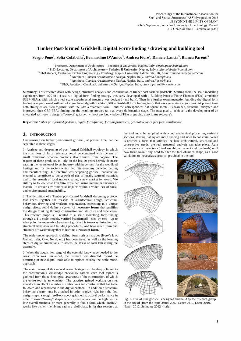
Fig. 1. Five of nine gridshells designed and build by the research group
in the city of (from the top): Ostuni 2007, Lecce 2010, Lecce 2010,
Napoli 2012, Selinunte 2012 - Italy.
2
2. BACKGROUND: THE TRANSITION FROM
"ANALOGICAL" DESIGN METHOD TO THE "HYBRID"
ONE
In the analogical phase of this research, great importance was given to
the study of twentieth century's great engineers and architects (Antoni
Gaudì, Frei Otto, Pierluigi Nervi, Eduardo Torroja, Heinz Isler, Franz
Dischinger, etc) on complex geometry structures, especially those
concerning simulations of forms derived from the structures found in
nature [1], in which there is a balance of forces according to the "Form-
finding" principles. In particular, we analyzed the ways in which
Mannheim Lattice Shell scaled models were made, from preliminary
steps up to the executive, through the vector drawings expressed by prof.
Klaus Linkwitz with the support of the Institut für Anwendungen Der
Geodäsie im Bauwesen - Universität Stuttgart, by the photographic and
mathematical methods he had developed during the design of the
German Federal Pavilion at Montreal and the Munich Olympic stadia [2]
It was needed the measurement of the hanging scaled model to obtain
the initial shape of the gridshell to submit to a series of structural
verifications in a recursive sequence of curvature radii adjustments.
Because of the unprecedented complexity and dimension of this
structure, it was necessary a close integration between physical models
testing and the limited computer analysis possibilities available at 1973
[2][3].
The chosen funicular shape, already experimented in Frei Otto tensile
structures, was only a starting point, not strictly necessary for a
lightweight structure, as explained by Ted Happold and Ian Liddel: «The
shape for the shell is established by photogrammetric measurement of a
hanging chain model and is funicular. If the shell is loaded with its own
weight only, no bending forces result. This is an ideal condition, as in
practice the imposed loads on the shell are greater than the self-weight
and are not uniformly distributed at the nodes. A funicular shape is an
advantage but is not essential.» [2]
Therefore, it's not surprising that the Weald & Downland Open Air
Museum gridshell shape was developed from non-funicular models,
thus, its structure doesn’t reacts in pure compression scheme under self
weight [3].
During the long phase of our research on achievable lightweight
structures form-finding methods referenced to timber post-formed
gridshell, we started from Happold and Liddell statements, bypassing
hanging models and trying to find out a new method for a different
form-finding that had to return information about the correctness of the
tectonic choices.
Firstly, scaled models were made of wire mesh mosquito nets; this
material, very malleable, was perfect to follow the desired shape,
although completely ineffective for a first strength testing, see fig. 2.
Fig. 2. Scaled models made of mosquito nets
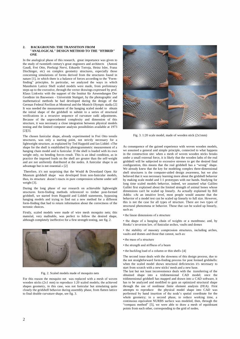
For this reason the mosquito net was replaced with a mesh of woven
wooden sticks (2x1 mm) to reproduce 1:20 scaled models; the achieved
shapes geometry, in this case, was not funicular but simulating quite
closely the gridshell behavior during assembly phase, from flatten lattice
to final double curvature shape, see fig. 3.
Fig. 3. 1:20 scale model, made of wooden stick (2x1mm)
As consequence of the gained experience with woven wooden models,
we assumed a general and simple principle, connected to what happens
in the construction site: when a mesh of woven wooden sticks breaks
under a small external force, it is likely that the wooden laths of the real
gridshell will be subjected to excessive stresses to get the desired final
configuration, this means that the real gridshell has a “wrong” shape.
We already knew that the key for modeling complex three-dimensional
shell structures is the computer-aided design awareness, but we also
believed that it was necessary learning more about the gridshell behavior
by making scale model and 1:1 prototypes with our hands. Studying for
long time scaled models behavior, indeed, we assumed what Galileo
Galilei first explained about the limited strength of animal bones whose
dimensions can't be scaled up linearly. As actually explained by Bill
Addis: «At an intuitive level, most people would assume that the
behavior of a model test can be scaled up linearly to full size. However,
this is not the case for all types of structure. There are two types of
structural phenomena or behavior. Those that can be scaled up linearly,
such as:
• the linear dimensions of a structure
• the shape of a hanging chain of weights or a membrane; and, by
Hooke’s inversion law, of funicular arches, vaults and domes
• the stability of masonry compression structures, including arches,
vaults and domes and those that cannot, such as:
• the mass of a structure
• the strength and stiffness of a beam
• the buckling load of a column or thin shell» [4]
The second issue deals with the slowness of this design process, due to
the not straightforward form-finding process for post formed gridshells:
when the scaled model shows structural deficiencies it's necessary to
start from scratch with a new sticks' mesh and a new base.
The last but not least inconvenience deals with the transferring of the
obtained shape into a tridimensional CAD model; once the
tridimensional gridshell has mapped and drawn into a CAD software, it
has to be analyzed and modified to gain an optimized structural shape
through the use of nonlinear finite element analysis (FEA). First
attempts to reproduce the physical model shape into CAD was
performed by hand insertion of the node’s spatial coordinate for the
whole geometry; in a second phase, to reduce working time, a
continuous equivalent NURBS surface was modeled, then, through the
“compass method” [5], we were able to draw a mesh of equidistant
points from each other, corresponding to the grid of nodes.

Proceedings of the International Association for
Shell and Spatial Structures (IASS) Symposium 2013
„BEYOND THE LIMITS OF MAN”
23-27 September, Wroclaw University of Technology, Poland
J.B. Obrębski and R. Tarczewski (eds.)
3
This method was faster and more accurate, although the reliability of the
virtual geometry would still be affected by the surveying accuracy. In
addition, very approximate information in terms of stresses can be
obtained.
A completely different experiment has been developed for a 600 sqm
gridshell (never built); here we tried to better reproduce the behavior of
the real structure by modeling in deep detail the gridshell technology: a
tin pin simulating the bolt and the flat lattice was made up of modules in
imitation of real 3x3 m wooden laths modules. At the end of this process
we were able to get a vector tridimensional drawing thanks to a 3D laser
scanner: an equivalent Point cloud was the raw output from which we
deduced the corresponding mesh with vertices at each connection among
laths, thus the mesh edges coinciding to the laths axis. This interesting
procedure has been lately discarded because of its complexity especially
due to the need of cleaning up the vector model from all the physical
model inaccuracies, too faithfully reported by the scanner., see fig. 4.
Fig. 4. Left: Transformation of a double curved surface in a net mesh.
Right: drawing by 3d scanner
In conclusion, since making the scale model of a gridshell was the first
step of our design procedure, the whole process resulted too slow yet: as
the input parameters for the form-finding simulation come from physical
model, a change in the shape required the making of a new scale model
and so on. Perhaps we should have established a scientific relationship
between the performance of the scaled mesh of woven wooden sticks
and the full-size prototype. But we didn't; we rather preferred
proceeding with the deepening of digital form-finding method.
For this reason, an important goal in our research has been achieved
with a computer methodology for digital form-finding procedure with
the Abaqus [6] finite element software developed by Bernardino
D’Amico [7].
In this case, with a given flat lattice geometry and the vector of imposing
displacements (both previously found by scale models) a geometrically
nonlinear finite element analysis is set to simulate once more the
forming process. Further, bending strength verification is performed for
each beam element, assessing the laths cross section for timber strength
and elastic modulus variation. The implicit FE analysis requires a high
computational time, as well as the setting of imposed displacements to
be carefully calibrated in order to avoid small iterations values, so to
achieve eventually the solution’s convergence. For this reason the FE
analysis is performer in a latter design stage, with flat lattice geometry
previously defined by scale model. The need of solving a highly
nonlinear system involving large displacements (as the case) explain
why dynamic (or pseudo dynamic) explicit analyses are the most
followed approach so far [8][9] one for all: the Dynamic Relaxation
method [10][11]. Nevertheless, the development of a form-finding tool
for post formed grid-shells based on static nonlinear FE analysis is
currently under development at the Centre for Timber Engineering of
Edinburgh Napier University [12], see fig. 5.
Fig. 5. Simulation process in Abaqus
Another method to bypass the need of physical models has been
proposed by Kuijvenhoven [9] consisting of a tool which performs, in a
first step, the forcing of a general flat grid onto an imposed surface while
in a second step, boundary constraint are added and the exceeding grid
and external forces (springs jointed between grid and target surface) are
deleted so the grid settles again to its final shape. Although this tool
represents a novel approach to the problem, it remains as general design
method, not usefully applicable for professional practice. In fact only
grid-shell with a "continuous" and "plane" boundary curve can be
performed, which means that no gates and no spatial boundary curve
(like in the Savill Garden grid-shell) can be considered.
3. THE TRANSITION FROM THE HYBRID TO THE
DIGITAL DESIGN METHOD: THEORETICAL ASPECTS
One of the main objectives throughout our research about the gridshell is
the development of a software, smoothly applicable and with a plan
interface, in order to allow the designer to anticipate, already at the
preliminary level, a substantially correct form and compatible with the
construction method that will be used. This particular type of digital
Form Finding, in fact, should contain all the information related to the
behavior of gridshell, both during the construction phase that during its
design life cycle, with the scope of easily configure the architectural
form but also the flat grid which will generate the surface itself. The
immediacy of the digital process is not yet fully achieved and is one of
the topics for future studies. It is clear, in fact, that the ease of use for the
program is the last piece with respect to the knowledge of the great
complexity of this building process, from the technological aspects to
the structural ones, without which the software itself would be
configured as one of many generators of complex shapes already present
in the field of form resistant structures. For this reason, once defined the
general protocol that goes from the preliminary drafts until buildable, it
became necessary to create two specific software: an engineering tool
specific to the research group and one specifically built for the
architectural design supplied with a database for designs types, types of
wood, construction materials, details and cost estimates, in order to
finally enter the wooden post-formed gridshell into the panorama of
widespread architecture as a consequence of the improvement in data
exchange and working flow efficiency among the different figures
involved in the whole production process (architect, structural engineer,
supplier, contractor, etc.) industry.

4
The transition from the analog form-finding process to the digital one,
which uses of software for the three-dimensional representation
according parametric algorithms, replaces (with a real-time control of
the shape) the slow, repetitive and non-reversible phases concerning
the analog method.
This process has started with the occasion of the graduation thesis by
Andrea Fiore and Daniele Lancia [13], for which we set ourselves the
objective of creating a digital tool that would have allowed to design in a
fast and flexible way a plausible gridshell’s shape starting defining the
problem in terms of architectural requirements (footprint, height, size,
position and number of entrances), without passing through the
realization of a timber model.
The aim was to develop a proper computerized shape research
methodology called Gfft (Gridshell Form Finding Tool) peculiar for
post-formed gridshell. The method uses as a base platform a three-
dimensional graphics software particularly suitable for complex
geometries and for the free form on which are grafted some plug-ins that
make their operation more suitable for the heuristic phase of the project.
In particular, the first application allows to configure the forms in a
parametric way through some steps of simplified programming.
Basically, instead of drawing an object it is necessary to configure the
logical, mathematical and geometric path leading to that specific form.
Fig. 6. Gfft workflow
Ex post facto, the software remembers each step and, at any time, the
user may modify the data: for example, the first step requires the design
of the flat grid: using the gridshell form finding tool, the user can change
the shape and dimension of the grid by simply drawing a new cutting
line.
In the same way, the user can proceed to the subsequent steps, where he
can change the position of an external constraint or the strength needed
to force the grid to assume its final shape. This goal has been achieved
using another plug-in, necessary to introduce physical parameters of the
chosen sections and materials.
The results of this new process offered, after a suitable calibration
procedure, comparable and even overlapping results with the previous
method, by the addition of more control options of the obtained shape.
The user can immediately display, through a different coloring of the
rods, their level of deformation so cheking in real time, which of these
exceeded the maximum limits of curvature and, consequently, correct
the errors in the shaping.
4. THE GFFT DESIGN TOOL
The tool has been developed as extension of third part existing CAD
software by using Grasshopper, a freeware available plug-ins for
scripting by visual interface, thus allowing the user to create generative
algorithms without having strong programming skills.
4.1. Input
The gained experience, both in terms of scale model shaping that on-site
hand-work, represented the starting point for the definition of the tool’s
framework, and input definition, which can summarized as follow:
Starting flat grid: one or more orthogonal overlapping layers
made of laths following a given direction.
Intermediate connection: cylindrical hinges positioned at
50cm spans for both orthogonal direction.
Timber species: as a function of several parameters (home-
grown species availability and suitability to required design
service class)
Laths direction: the structural behavior varies as function of
the lattice weave.
Bracing: the gridshell structural behavior is highly dependent
of the presence/absence and direction of brace elements.
4.1.1. Starting flat lattice
The gridshell is made of an equal pair of layers. The amount of pairs and
the laths cross sectional thickness are designed in order to resist the
working life actions. The firs built prototype in Ostuni, was made of just
one couple of layers for the boundary arches. In the following
realizations we opted to use four layer of laths, thus increasing the
bending stiffening of the arches. Each lath is modeled by its centroid
axis. Further improvements of the geometrical model regard the offset
between layers, firstly ignored in the early model assumptions. The
updated lattice geometry with layer offset gave a more realistic
representation of the real structure.
Equivalent numerical model of the starting flat lattice:
The lattice is geometrically defined by the shape of the polygon
corresponding to the lattice cutting silhouette while the distance among
internal nodes is ruled by a length parameter “L” (40cm < L < 60cm);
The axial and bending stiffness for each element is computed as a
function of the elastic modulus and inertia and area cross section, see
fig. 7.

Proceedings of the International Association for
Shell and Spatial Structures (IASS) Symposium 2013
„BEYOND THE LIMITS OF MAN”
23-27 September, Wroclaw University of Technology, Poland
J.B. Obrębski and R. Tarczewski (eds.)
5
Fig. 7. Example of geometry cutting
4.1.2. Connections
The element of connection between the two layers (bolt) allows only the
rotation around its longitudinal axis while the remaining five degree of
freedom (two rotation and three translation) are assumed as fixed. This
notation, resulted to be very important, making the difference with the
other software analyzed in the study cases, where the assumption of a
fixed distance among node connection is ignored. In our case, this
represents an important issue since requirements such as lightweight,
fast on-site assembling, easy transportation an cost efficiently represents
key points of our research. In particular the patented connection
technology [15], see fig.8, is the outcome of our willing to maximize the
prefabrication factor. This kind of connection allows to assembling the
grid in macro-modulus, to be posed and joint together once on the on-
site working ground. For this reason, the connection has to work in three
different circumstances: transportation, erection (forming), life-cycle.
This simple “machine-node” allows the macro-modulus assembling in
the first step, the laths rotation in the second step and the proper
structural role once bracing are added to the primary structure. The node
distance is set at 50cm, which is slightly higher than the distance among
studs for balloon frame (40cm) and the same of Mannheim Lattice Shell
(50 cm).
Numerical modeling of the cylindrical joint in the Gfft:
Initially, the intermediate joints between x and y rods were treated like
points (particles), thus transforming the resulting mesh in a double
curved surface. Therefore, to simulate the real structural behavior of the
deformed mesh, we have chosen to draw the four laths as four
superimposed layers, to be connected with a joint. In this way, x and y
rods are placed at their real distance, corresponding to the chosen lath
section.
Fig. 8. The patented connection technology
4.1.3. Material properties
Suitable wood species to make timber laths for post-formed gridshells
have to present a good decay resistence against external/environmental
factors and high bending-strength/elastic-modulus ratio as well (fm/E):
so far we experimented conifer (with spruce, larch, pine) and broadleaf
(chestnut) species. Experimental tests were carried out time to time on
the timber species used in order to characterize the strength and stiffness
values (bending strength, elastic modulus parallel to the gain). Wood is a
non-homogeneous material, in addition, the laths cross section is
relatively small (if compared to sizes usually used for “common” timber
structures). For this reason, the presence of defects (knots, slope grain,
etc) increase the deviation between mean and characteristic strength
values for a given lumber population to be graded.
Material properties definition into the Gfft:
Objective for future improvements of the Gfft tool is the inclusion of a
material library to take into account the mechanical properties of the
chosen wood species. Currently, these data (Elastic modulus parallel to
the gain, Shear modulus) are manually inputted into the tool control
panel together with the inertia cross section.
4.1.4. Rotation of the flat grid starting from the boundary
constraints
The rotation of the mesh, relative to the boundary, is a topical issue to be
managed through the software to reach an optimized structural solution.
For any chosen rotation, all the layers have to reach the boundary lines
to guarantee an uniform reaction to strains of the whole gridshell.
The same model, in fact, with the same free edges and constraints, reacts
in a completely different way depending on the rotation (45°-90 °)
between the lattice and the boundary. The definition of boundary
constraint configuration on the ground (shape and position) is, at the
same time, a central issue of the tool, given their important function in
gridshell global resistance and for the overall resulting shape.
Rotation of the flatten grid relatively to the boundary constraints in the
Gfft:
In the Gff tool, the user selects the sides of the perimeter corresponding
to the boundaries on the ground. These lines, during the shaping
generation, are attracted to the pre-defined boundary curves. Depending
on the rotation of the boundaries constraints (45°-90°), this strain (of
6
attraction or repulsion) allows to modify the rhombus shape nearby the
ground constraints as well as the boundary curve length. These
boundaries can be drawn as polylines, splines or arcs; modifying their
geometry and position, the user can evaluate in real time the
architectonic and structural effect of these modifications on the overall
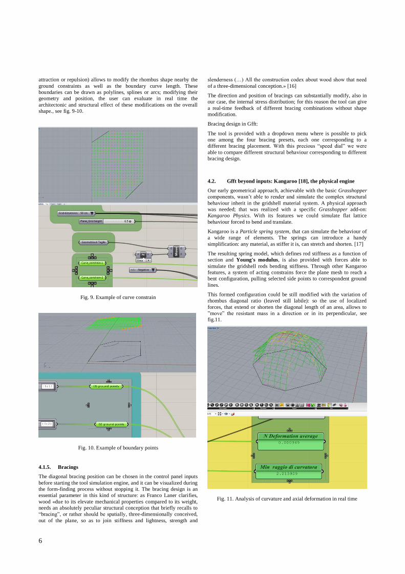
shape., see fig. 9-10.
Fig. 9. Example of curve constrain
Fig. 10. Example of boundary points
4.1.5. Bracings
The diagonal bracing position can be chosen in the control panel inputs
before starting the tool simulation engine, and it can be visualized during
the form-finding process without stopping it. The bracing design is an
essential parameter in this kind of structure: as Franco Laner clarifies,
wood «due to its elevate mechanical properties compared to its weight,
needs an absolutely peculiar structural conception that briefly recalls to
“bracing”, or rather should be spatially, three-dimensionally conceived,
out of the plane, so as to join stiffness and lightness, strength and
slenderness (…) All the construction codex about wood show that need
of a three-dimensional conception.» [16]
The direction and position of bracings can substantially modify, also in
our case, the internal stress distribution; for this reason the tool can give
a real-time feedback of different bracing combinations without shape
modification.
Bracing design in Gfft:
The tool is provided with a dropdown menu where is possible to pick
one among the four bracing presets, each one corresponding to a
different bracing placement. With this precious “speed dial” we were
able to compare different structural behaviour corresponding to different
bracing design.
4.2. Gfft beyond inputs: Kangaroo [18], the physical engine
Our early geometrical approach, achievable with the basic Grasshopper
components, wasn’t able to render and simulate the complex structural
behaviour inherit in the gridshell material system. A physical approach
was needed; that was realized with a specific Grasshopper add-on:
Kangaroo Physics. With its features we could simulate flat lattice
behaviour forced to bend and translate.
Kangaroo is a Particle spring system, that can simulate the behaviour of
a wide range of elements. The springs can introduce a handy
simplification: any material, as stiffer it is, can stretch and shorten. [17]
The resulting spring model, which defines rod stiffness as a function of
section and Young's modulus, is also provided with forces able to
simulate the gridshell rods bending stiffness. Through other Kangaroo
features, a system of acting constrains force the plane mesh to reach a
bent configuration, pulling selected side points to correspondent ground
lines.
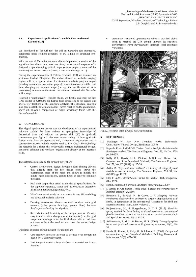
This formed configuration could be still modified with the variation of
rhombus diagonal ratio (leaved still labile): so the use of localized
forces, that extend or shorten the diagonal length of an area, allows to
”move” the resistant mass in a direction or in its perpendicular, see
fig.11.
Fig. 11. Analysis of curvature and axial deformation in real time
Proceedings of the International Association for
Shell and Spatial Structures (IASS) Symposium 2013
„BEYOND THE LIMITS OF MAN”
23-27 September, Wroclaw University of Technology, Poland
J.B. Obrębski and R. Tarczewski (eds.)
7
4.3. Experimental application of a module Fem on the tool:
Karamba [19]
We introduced in the Gff tool the add-on Karamba (an interactive,
parametric finite element program) to try a kind of structural pre-
analysis.
With the use of Karamba we were able to implement a section of the
algorithm that allows us to test, real time, the structural response of a
designed shape, through graphical output (efforts graphics, colors of the
elements) and numeric output (stress, strain, strain energy, etc.. ).
During the experimentation of Toledo Gridshell, [13] we assumed an
accidental load of 150kg/sqm. The add-on allowed us, with the shaping
engine still on, a typical view of a structural analysis program output
(bending moment and curvature graphs). It was therefore possible, real
time, changing the structure shape (through the modification of form
parameters) to minimize the stress concentration detected with Karamba
at first steps.
Reached a "qualitatively" feasible shape, we finally analyzed the last
CAD model in SAP2000 for further form-improving to be carried out
after a few iterations of the structural analysis. This structural analysis
also gave us all the information about forces reaction on the ground and,
above all, allows a comparison of outpts previously found with the
Karamba module.
5. CONCLUSIONS
This digital application proves that the developing of an experimental
software couldn’t be done without an appropriate knowledge of
theoretical issue and without an proper skill [20] in gridshell
construction (see fig. 12): the deep understanding of how gridshell
design arises from an expressive will, a structural requirement and a
constructive process, which together tend to Frei Otto's Form-finding:
the research for a shape that reciprocally merges architectural design,
structural behavior and worksite organization already at the heuristic
stage.
The outcomes achieved so far through the Gfft are:
Correct architectural design through a form-finding process
that, already from the first design steps, shows the
overstressed areas of the mesh and allows to modify the
inputs (mesh dimensions, ground lines) in order to optimize
the shape.
Real time output data useful to the design specifications for
the suppliers (quantity, sizes) and the contractor (assembly
instruction, fabrication graphics, etc.).
Wireframe model ready to be exported in any 3D modelling
and structural analysis software.
Drawing automation: there’s no need to draw each grid
element (laths, pivots, bracings, ground lines) because
they’re just defined by the algorithm.
Reversibility and flexibility of the design process: it’s very
easy to make minor changes to all the inputs (i. e. flat grid
shape and spacing) or to the final shape with a real time
outcome without the need to start over the entire design
process.
Outcomes expected during the next few months are:
User friendly interface: in order to be used even though the
user is not a computer expert.
Tool integration with a large database of material mechanics
features.
Automatic structural optimization: when a satisfied global
form is reached the Gfft should improve its structural
performance (form-improvement) thorough local automatic
variations.
Fig.12. Research team at work: www.gridshell.it
6. REFERENCES
[1] Nerdinger W., Frei Otto. Complete Works: Lightweight
Construction Natural Design, Birkhauser (2005).
[2] Happold E and Liddell WI, Timber Lattice Roof for the Mannheim
Bundesgartenshau. The Structural Engineer, Vol. 53, No. 3 (1975)
pp. 99-135.
[3] Kelly O.J., Harris R.J.L, Dickson M.G.T and Rowe J.A,.
Construction of the Downland Gridshell, The Structural Engineer,
Vol. 79, No. 17, (2001) pp. 25-33.
[4] Addis, B, 'Toys that save millions' - a history of using physical
models in structural design, The Structural Engineer, Vol. 91, No.
4 (2013) pp. 12-27.
[5] Otto F. IL10 Gitterschalen. Institut für leichte Flächentragwerke
(IL), 1974.
[6] Hibbit, Karlson & Sorenson. ABAQUS theory manual. 2007
[7] D’Amico B. Graduation Thesis titled ‘Design and construction of
a timber gridshell’, (2010).
[8] Bouhaya, L., Baverel, O., & Caron, J. F. Mapping two-way
continuous elastic grid on an imposed surface: Application to grid
shells. In Symposium of the International Association for Shell and
Spatial Structures (50th. 2009. Valencia).
[9] Kuijvenhoven, M., & Hoogenboom, P. C. J. (2012). Particle-
spring method for form finding grid shell structures consisting of
flexible members. Journal of the International Association for Shell
and Spatial Structures, 53(1), 31-38.
[10] Adriaenssens, S. M. L., & Barnes, M. R. (2001). Tensegrity spline
beam and grid shell structures. Engineering structures, 23(1), 29-
36.
[11] Harris, R., Romer, J., Kelly, O., & Johnson, S. (2003). Design and
construction of the Downland Gridshell. Building Research &
Information, 31(6), 427-454.
8
[12] D’Amico, B. Form-finding and structural optimization of timber
gridshell structures. In The Institution of Structural Engineers
Young Researchers’ conference (15th, 2013. London).
[13] Fiore A., Lancia D., Digital form finding and construction of a
timber post-formed gridshell, Graduation Thesis, Supervisor
Sergio Pone, co-supervisor, Francesco Portioli, Sofia Colabella,
Bianca Parenti and Bernardino D’Amico.
[14] L10: Gitterschalen – Grid Shells, Institut für leichte
Flächentragwerke (IL)/ Karl Krämer Verlag, Stuttgart (1974).
[15] Patent n. 0001394107, Elemento strutturale per una costruzione
gridshell, costruzione gridshell includente detto elemento e
procedimento per realizzare tale costruzione impiegando detto
elemento, 31.06.2012.
[16] Laner F., Vecchi morfemi per nuovi tecnemi, «Materia», n. 36,
2001, p. 24.
[17] Watkin A., Physically Based Modeling - Particle System
Dynamics, Pixar Animation Studios, 1997.
[18] http://www.grasshopper3d.com/group/kangaroo
[19] http://www.karamba3d.com/
[20] Pone, S., Gridshell. I gusci a graticcio in legno tra innovazione e
sperimentazione, Alinea, Firenze, (2012).
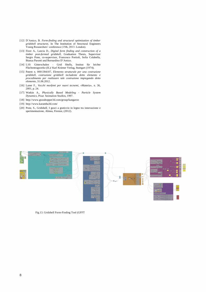
Fig.13. Gridshell Form-Finding Tool (GFFT
Related Documents