627 WOOD RESEARCH 59 (4): 2014 627-638 TIMBER – CONCRETE COMPOSITE ELEMENTS WITH VARIOUS COMPOSITE CONNECTIONS PART 2: GROOVED CONNECTION Ján Kanócz Technical University of Košice, Faculty of Art Košice, Slovak Republic Viktória Bajzecerová Technical University of Košice, Faculty of Civil Engineering Košice, Slovak Republic Štefan Šteller Pulp and Paper Research Institute, Dept. Slovak Forest Product Research Institute Bratislava, Slovak Republic (Received February 2014) ABSTRACT Theoretical and experimental investigations of timber-concrete composite structural element consisting of the vertically nailed timber planks with fiber reinforced concrete on the top will be described. Within the experimental works four point short and long term bending tests were carried out on the composite beams. In middle of the beams span vertical displacements were gauged and also deformations in the beam´s middle cross section were detected. To determine the shear parameters of the grooved composite connection, short term shear tests were performed. For theoretical analysis with short term loading the presented calculation model for rigid connection, with long term loading analytical model presented in “Part 1”of this paper was applied. Comparison and analysis of the received results will be presented. KEYWORDS: Timber-concrete composite, grooved connection, shear test, short term bending test, long term behavior. INTRODUCTION This paper is the second part of the series of papers describing theoretical analysis and experimental investigations of various timber-concrete composite slab systems in the framework

Welcome message from author
This document is posted to help you gain knowledge. Please leave a comment to let me know what you think about it! Share it to your friends and learn new things together.
Transcript

627
WOOD RESEARCH 59 (4): 2014 627-638
TIMBER – CONCRETE COMPOSITE ELEMENTS WITH
VARIOUS COMPOSITE CONNECTIONS
PART 2: GROOVED CONNECTION
Ján KanóczTechnical University of Košice, Faculty of Art
Košice, Slovak Republic
Viktória BajzecerováTechnical University of Košice, Faculty of Civil Engineering
Košice, Slovak Republic
Štefan ŠtellerPulp and Paper Research Institute, Dept. Slovak Forest Product Research
InstituteBratislava, Slovak Republic
(Received February 2014)
ABSTRACT
Theoretical and experimental investigations of timber-concrete composite structural element consisting of the vertically nailed timber planks with fiber reinforced concrete on the top will be described. Within the experimental works four point short and long term bending tests were carried out on the composite beams. In middle of the beams span vertical displacements were gauged and also deformations in the beam s middle cross section were detected. To determine the shear parameters of the grooved composite connection, short term shear tests were performed. For theoretical analysis with short term loading the presented calculation model for rigid connection, with long term loading analytical model presented in “Part 1”of this paper was applied. Comparison and analysis of the received results will be presented.
KEYWORDS: Timber-concrete composite, grooved connection, shear test, short term bending test, long term behavior.
INTRODUCTION
This paper is the second part of the series of papers describing theoretical analysis and experimental investigations of various timber-concrete composite slab systems in the framework
628
WOOD RESEARCH
of the research project oriented to their different composite connection under short and long term loading.
At the first phase of the project, timber-concrete composite beams with screwed composite connection were investigated (Kanócz et al. 2013). At the next phase, the composite deck system consisting of the vertically laminated nailed timber plate with fiber reinforced concrete on the top was examined. Shear connection between the concrete layer and timber members with grooves in timber members was performed. The main purpose of the project was to determine several structural characteristics of both timber-concrete composite systems and based on the experimental tests determine suitable theoretical calculation models for investigated composite members under the short and long term static loading.
This paper describes real response and theoretical modeling of composite beams consisting of vertically laminated nailed timber planks with grooved composite connection.
In present time, number of various types of wood-concrete composite structural elements was developed for the different type of building and bridge bearing systems. The wood part of composite deck is created not only as a pattern of single timber beams but also as the vertically laminated wood deck (Natterer et al. (1996), Lehmann et al. (2001)) or deck produced from the wood planks as longitudinal cells arranged side by side. Connection between the layer of concrete and wood may to be performed by various ways. Applying the mechanical dowel-type fasteners the semi rigid connection is received, which is characterized by the specific degree of f lexibility depending on the type, placement and other properties of the used fasteners. The use of the dowel-type fasteners for the vertically nailed decks brings number of difficulties (Rajčič 1998). Therefore other systems of shear connections were developed as a longitudinally or perpendicular glued-in metal plates. More simple solution is grooves moulded in the timber members for the shear transfer between the concrete layer and vertically nailed deck. Number of investigations confirms the high efficiency of the grooves which provide highly rigid and ductile shear connection (Kuhlmann and Schänzlin 2001). The concrete layer of composite member requires additional reinforcement to avoid cracks due to shrinkage. This reinforcement traditionally consists from the steel reinforce bars but also fiber reinforcement of concrete layer were tested (Heiduschke and Kasal 2003).
Calculation model of timber-concrete composite beams considering the semi rigid connection was mentioned in (Kanócz et al. 2013). In this paper the calculation model considering the groove as rigid connection is presented. Results of the rigid and semi-rigid theoretical model ware compared with measured data from short and long term loading test.
MATERIAL AND METHODS
Characteristic of the specimens and materialsTo investigate composite timber–concrete system with vertically nailed planks, real-size
specimens were suggested. The 5.0 m long beam with 340.0 mm depth and 315.0 mm width of cross section was built from 7 vertically nailed timber planks 45.0 x 260.0 mm cross section. Thickness of the concrete layer was 80.0 mm and the grooves depth was 30.0 mm. The length and number of grooves was determined by preliminary calculation (Fig. 1). Softwood - spruce with grade C24 and concrete with grade C25/30 was applied. The problematic side of this composite system, mainly from the point of view of long term action, is the shrinkage of the wood and concrete respectively. To eliminate the influence of this phenomenon, steel fiber reinforced concrete was used for beam specimens. This type of reinforcement, besides eliminating the cracks
629
Vol. 59 (4): 2014
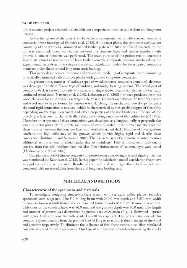
due to shrinkage of concrete, also improves the strength parameters of concrete layer which leads to the high performance composite action of the beam. To decrease the influence of wood shrinkage to the groove connection, in each second timber planks the grooves position was shifted by the half length of groove (Fig. 2).
Fig. 1: Cross-section and side view of the composite vertically nailed plank beam with grooves.
Fig. 2: Grooves pattern in the laminated timber part.
The required mechanical parameter of used wood and concrete was determined separately for the both material according to the relevant standards. See overview in Tab. 1 and Tab. 2.
Tab. 1: Parameters of the concrete.
Compressive strength 32.7 MPaTensile strength in bending 5.4 MPa
E-Modulus 30400 MPaDensity 2342 kg.m-3
Thermal expansion coefficient 1.0.10-5 °C-1
Tab. 2: Parameters of the timber.
Bending strength 25.3 MPaShear strength 6.66 MPa
E-Modulus 9562 MPaMoisture content 14.2 %
Density 435 kg.m-3
Thermal expansion coefficient of timber 5.0.10-6 °C-1Humidity expansion coefficient of timber 3.0.10-3
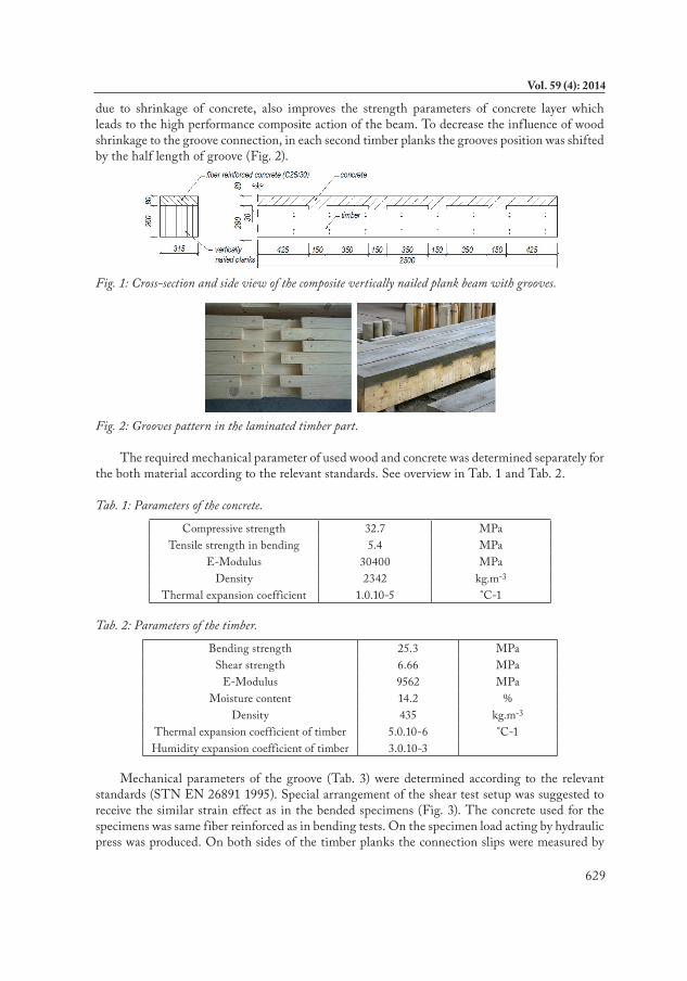
Mechanical parameters of the groove (Tab. 3) were determined according to the relevant standards (STN EN 26891 1995). Special arrangement of the shear test setup was suggested to receive the similar strain effect as in the bended specimens (Fig. 3). The concrete used for the specimens was same fiber reinforced as in bending tests. On the specimen load acting by hydraulic press was produced. On both sides of the timber planks the connection slips were measured by
630
WOOD RESEARCH
digital gauges. The loading schedule was suggested with the unloading process after attainment of 40 % of estimated failure load level. After the unloading process the load increased up to the failure of the connection. The mode of failure in all shear test specimens of grooved connection was similar. After attainment of ultimate load level, the shear failure of concrete occurred.
Tab. 3: Parameters of the groove.
Instantaneous slip modulus kN.mm-1 26.7Load carrying capacity kN 26
Fig. 3: Setup of the shear tests, failure mode and load–slip diagram.
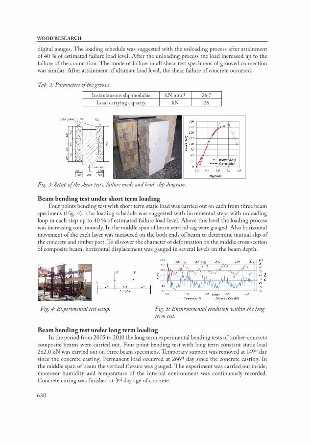
Beam bending test under short term loadingFour points bending test with short term static load was carried out on each from three beam
specimens (Fig. 4). The loading schedule was suggested with incremental steps with unloading loop in each step up to 40 % of estimated failure load level. Above this level the loading process was increasing continuously. In the middle span of beam vertical sag were gauged. Also horizontal movement of the each layer was measured on the both ends of beam to determine mutual slip of the concrete and timber part. To discover the character of deformation on the middle cross section of composite beam, horizontal displacement was gauged in several levels on the beam depth.
Fig. 4: Experimental test setup. Fig. 5: Environmental condition within the long
term test.
Beam bending test under long term loadingIn the period from 2005 to 2010 the long term experimental bending tests of timber-concrete
composite beams were carried out. Four point bending test with long term constant static load 2x2.0 kN was carried out on three beam specimens. Temporary support was removed at 149st day since the concrete casting. Permanent load occurred at 266st day since the concrete casting. In the middle span of beam the vertical f lexure was gauged. The experiment was carried out inside, moreover humidity and temperature of the internal environment was continuously recorded. Concrete curing was finished at 3rd day age of concrete.
631
Vol. 59 (4): 2014
Tab. 4: History of load application measured from the concrete casting.
Beginning of drying shrinkage “cs” 3 daysRemoval of temporary support - self weight “g” 149 days
Permanent load “F” 266 days
Tab. 5: Parameters of environment.
Average value of relative humidity 45 %Maximum value of relative humidity 66 %Minimum value of relative humidity 24 %
Average value of temperature 20.7 °CMaximum value of temperature 27.7 °CMinimum value of temperature 13.7 °C
Calculation model for the rigid connection
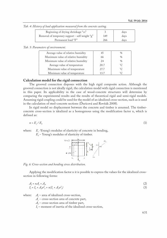
The grooved connection disposes with the high rigid composite action. Although the grooved connection is not ideally rigid, the calculation model with rigid connection is mentioned in this paper. Its applicability in the case of wood-concrete structures will determine by comparing the experimental results and the results of theoretical rigid and semi-rigid models. Assuming rigid coupling could be used for the model of an idealized cross-section, such as is used in the calculation of steel-concrete sections (Ďuricová and Rovňák 2008).
In rigid model no displacement between the concrete and timber is assumed. The timber-concrete cross-section is idealized as a homogenous using the modification factor n, which is defined as:
n = Ec / Et (1)
where: Ec -Young’s modulus of elasticity of concrete in bending, Et – Young’s modulus of elasticity of timber.
Fig. 6: Cross-section and bending stress distribution.
Applying the modification factor n it is possible to express the values for the idealized cross- section in following forms:
Ai = nAc + At, (2)Ii = It + Ata2t + n(Ic + Aca2c) (3)
where: Ai – area of idealized cross-section, Ac – cross-section area of concrete part, At – cross-section area of timber part, Ii – moment of inertia of the idealized cross-section,
632
WOOD RESEARCH
Ic - moment of inertia of concrete part, It - moment of inertia of the timber part.
The distance at between the center of gravity of the timber part and idealized cross section can be calculated as:
(4)
where: e – distance between the center of gravity of the wood and concrete part, ac - distance between the center of gravity of the concrete part and idealized cross section. Normal stress distribution in the timber-concrete composite cross-section (Fig. 6) is given
by:
(5)
(6)
The resistance of the timber-concrete composite beam is given by the ultimate stresses in the top and bottom edge of the concrete (7) or in the timber part (8) of cross-section, by the resistance of composite connection or by the ultimate beam deflection.
The ultimate moments in the top (Mu,c1) and bottom (Mu,c2) edge of the concrete part of the composite cross-section can be received from following strength conditions:
(7)
where: fcm- compressive strength of the concrete, fctm- tension strength of the concrete.
The ultimate moment (Mu,t) in timber part should be derived from the strength condition (8):
(8)
where: ft,0,d- ultimate tensile strength of the timber, fmd- bending strength of the timber.
In case of four points bending test according to Fig. 4, from the condition for ultimate moment, the resistance is possible to express with Eq. 9:
(9)
where: Mu,c2 - explicitly positive value of Mu,c2 derived from Eq. 5 is considered, g - self weight of the beam.
The resistance of composite connection of the beam depends on the load carrying capacity Fsu of applied connectors and can be derived from the following condition:
633
Vol. 59 (4): 2014
(10)
From the condition for limit deflection δlim, the resistance Fδu given by the ultimate displacement of the of the timber-concrete composite beam can be expressed:
(11)
An analytical calculation model of long term behavior of the timber-concrete composite beams was published in Kanócz at al. (2013). This model considers the most significant rheological phenomena such as: Viscous-elastic creep of concrete and wood, mechano-sorptive creep of wood, creep of shear connection, concrete shrinkage and strains due to thermal and relative humidity changes of environment and is applicable for simple beams with linear material properties and allows determining the final deflection in the middle span and stressing distribution in the middle cross- section of the composite beams affected by long term loading.
RESULTS AND DISCUSION
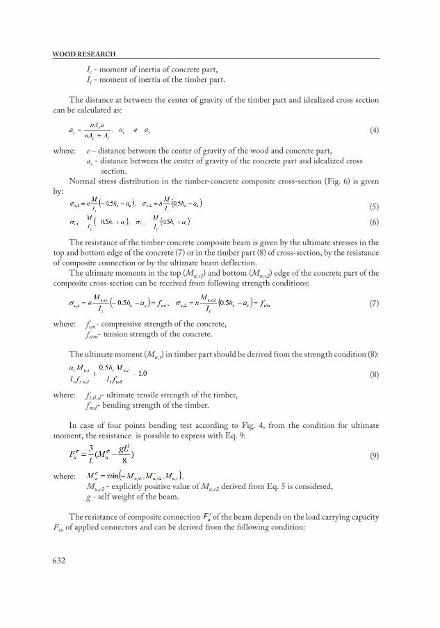
Short term loadingThe mode of failure in all vertically laminated composite beam specimens was similar.
Approximately on the 65 % of ultimate load level, shear cracks was occurred in the concrete on the side surface of grooves (Fig. 7). After the further increasing of load, cracks appear also in some timber lamellas. The cracks in timber occur mostly in locations near to various imperfections.
Fig. 7: Failure modes of the vertically laminated timber-concrete composite beam.
Fig. 8: Load – vertical displacement relationship in middle span.
Measured mid-span deflection values are presented on Fig. 8. Deflection-load relationships of all experimental beams seem similar and appear equivalent stiffness. Approximately on the load level of 80 kN, obvious stiffness decrease was occurred. This decrease was caused by attainment of ultimate tensile stress of some timber lamellas. To compare the stiffness of timber-concrete composite and plain timber beam, four points bending test of the vertically laminated timber beam with depth 260 mm was performed. The load-deflection relationship of the tested beams on Fig. 8 is presented. It shows, that the stiffness of the composite beams is 4 times higher comparing to the plain timber beam.
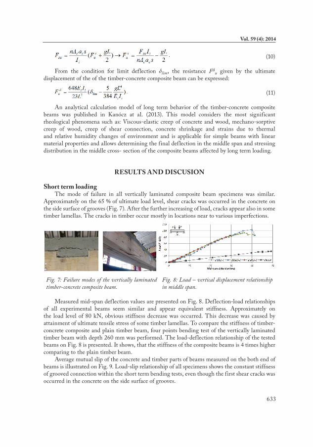
Average mutual slip of the concrete and timber parts of beams measured on the both end of beams is illustrated on Fig. 9. Load-slip relationship of all specimens shows the constant stiffness of grooved connection within the short term bending tests, even though the first shear cracks was occurred in the concrete on the side surface of grooves.
634
WOOD RESEARCH
Fig. 9: Load –horizontal slip relationship on the ends of beams.
Fig. 10: Strain and stress in middle cross section evaluated from measured deformation.
Strain and stress distribution was evaluated from the horizontal deformation measured in several levels on the beam depth (Fig. 10). The strain lines show the high stiffness of the groove composite connection. Using the strain values, stress distribution on the composite cross section was determined. In compressed zone the concrete part and in tensioned zone the timber part of cross section is located.
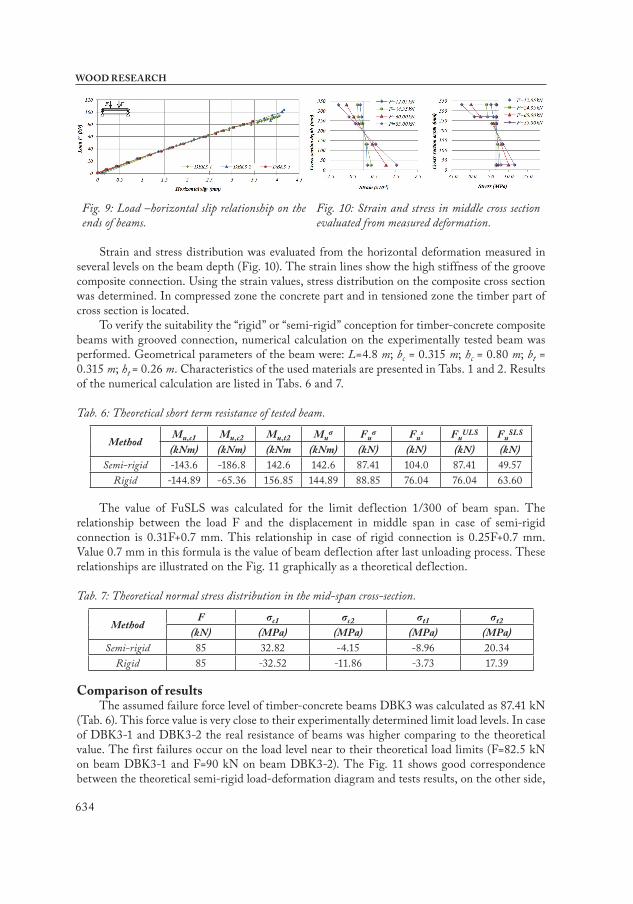
To verify the suitability the “rigid” or “semi-rigid” conception for timber-concrete composite beams with grooved connection, numerical calculation on the experimentally tested beam was performed. Geometrical parameters of the beam were: L=4.8 m; bc = 0.315 m; hc = 0.80 m; bt = 0.315 m; ht = 0.26 m. Characteristics of the used materials are presented in Tabs. 1 and 2. Results of the numerical calculation are listed in Tabs. 6 and 7.
Tab. 6: Theoretical short term resistance of tested beam.
MethodMu,c1 Mu,c2 Mu,t2 Muσ Fuσ Fus FuULS FuSLS
(kNm) (kNm) (kNm (kNm) (kN) (kN) (kN) (kN)Semi-rigid -143.6 -186.8 142.6 142.6 87.41 104.0 87.41 49.57
Rigid -144.89 -65.36 156.85 144.89 88.85 76.04 76.04 63.60
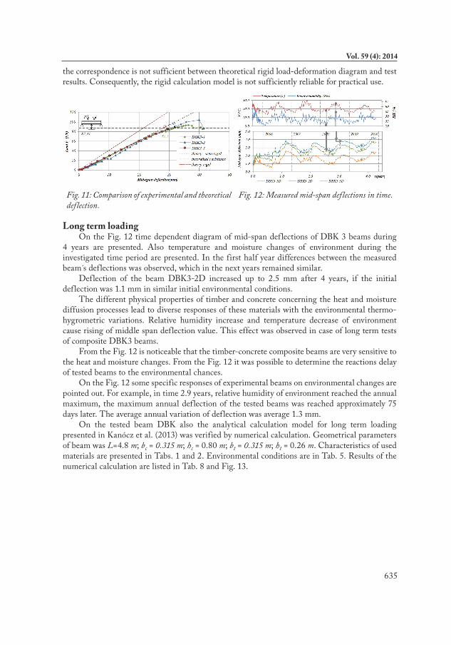
The value of FuSLS was calculated for the limit deflection 1/300 of beam span. The relationship between the load F and the displacement in middle span in case of semi-rigid connection is 0.31F+0.7 mm. This relationship in case of rigid connection is 0.25F+0.7 mm. Value 0.7 mm in this formula is the value of beam deflection after last unloading process. These relationships are illustrated on the Fig. 11 graphically as a theoretical deflection.
Tab. 7: Theoretical normal stress distribution in the mid-span cross-section.
MethodF σc1 σc2 σt1 σt2
(kN) (MPa) (MPa) (MPa) (MPa)Semi-rigid 85 32.82 -4.15 -8.96 20.34
Rigid 85 -32.52 -11.86 -3.73 17.39
Comparison of resultsThe assumed failure force level of timber-concrete beams DBK3 was calculated as 87.41 kN
(Tab. 6). This force value is very close to their experimentally determined limit load levels. In case of DBK3-1 and DBK3-2 the real resistance of beams was higher comparing to the theoretical value. The first failures occur on the load level near to their theoretical load limits (F=82.5 kN on beam DBK3-1 and F=90 kN on beam DBK3-2). The Fig. 11 shows good correspondence between the theoretical semi-rigid load-deformation diagram and tests results, on the other side,
635
Vol. 59 (4): 2014
the correspondence is not sufficient between theoretical rigid load-deformation diagram and test results. Consequently, the rigid calculation model is not sufficiently reliable for practical use.
Fig. 11: Comparison of experimental and theoretical deflection.
Fig. 12: Measured mid-span deflections in time.
Long term loadingOn the Fig. 12 time dependent diagram of mid-span deflections of DBK 3 beams during
4 years are presented. Also temperature and moisture changes of environment during the investigated time period are presented. In the first half year differences between the measured beam s deflections was observed, which in the next years remained similar.
Deflection of the beam DBK3-2D increased up to 2.5 mm after 4 years, if the initial deflection was 1.1 mm in similar initial environmental conditions.
The different physical properties of timber and concrete concerning the heat and moisture diffusion processes lead to diverse responses of these materials with the environmental thermo-hygrometric variations. Relative humidity increase and temperature decrease of environment cause rising of middle span deflection value. This effect was observed in case of long term tests of composite DBK3 beams.
From the Fig. 12 is noticeable that the timber-concrete composite beams are very sensitive to the heat and moisture changes. From the Fig. 12 it was possible to determine the reactions delay of tested beams to the environmental chances.
On the Fig. 12 some specific responses of experimental beams on environmental changes are pointed out. For example, in time 2.9 years, relative humidity of environment reached the annual maximum, the maximum annual deflection of the tested beams was reached approximately 75 days later. The average annual variation of deflection was average 1.3 mm.
On the tested beam DBK also the analytical calculation model for long term loading presented in Kanócz et al. (2013) was verified by numerical calculation. Geometrical parameters of beam was L=4.8 m; bc = 0.315 m; hc = 0.80 m; bt = 0.315 m; ht = 0.26 m. Characteristics of used materials are presented in Tabs. 1 and 2. Environmental conditions are in Tab. 5. Results of the numerical calculation are listed in Tab. 8 and Fig. 13.
636
WOOD RESEARCH
Tab. 8: Numerical calculation of mid-span deflection caused by long term load."Semi-rigid" "Rigid"
t φc Ec,eff φt Et,eff φf Keff (EI)ef δ Δδ (EI)ef δ Δδ
(days) (-) (MPa) (-) (MPa) (-) (N/mm) (MPa.mm4) (mm) (mm) (MPa.mm4) (mm) (mm)
Self weight
266 1.44 13114 0.50 6606 1.69 69413 6.913E+12 1.03 0,00 9.153E+12 0.78 0.001095 2.03 10693 1.14 4618 3.04 46206 4.950E+12 1.44 0,41 6.822E+12 1.04 0.271830 2.12 10420 1.41 4096 3.46 41886 4.501E+12 1.58 0,55 6.287E+12 1.13 0.35
∞ 2.24 10073 2.10 3187 4,34 34951 3.723E+12 1.91 0,88 5.325E+12 1.33 0.56
Permanent
load F
266 0.00 31980 0.00 9889 0.00 186795 1.307E+13 0.64 0,00 1.667E+13 0.50 0.001095 1.78 11632 1.10 4701 2.81 49080 5.159E+12 1.62 0,98 7.135E+12 1.17 0.671830 1.88 11288 1.40 4118 3,24 44024 4.644E+12 1.80 1,16 6.511E+12 1.28 0.78
∞ 2.00 10898 2.11 3182 4.10 36597 3.822E+12 2.19 1,55 5.479E+12 1.52 1.02
Concrete
shrinkage
266 3.70 6807 0.69 5842 3.20 44460 5.091E+12 3.85 0,00 6.436E+12 4.83 0.001095 4.45 5936 1.23 4433 4.68 32869 3.967E+12 4.40 0,55 5.187E+12 5.60 0-771830 4.61 5785 1.47 3998 5.21 30061 3.648E+12 4.55 0,70 4.837E+12 5.80 0-97
∞ 4.87 5568 2.11 3179 6.41 25203 3.053E+12 4.86 1,01 4.176E+12 6.19 1.37
Maximal middle span deflection variation caused by humidity changes δu was calculated as 2.01 mm, maximal deflection variation caused by thermal changes δT as 0.76 mm with considering the semi-rigid connection. In case of rigid connection the deflection variation δu was calculated as 2.28 mm and δT as 0.87 mm.
Expected measured mid-span deflection value of experimental beams in time t =1830 days measured from concrete casting can vary:
Comparison of results
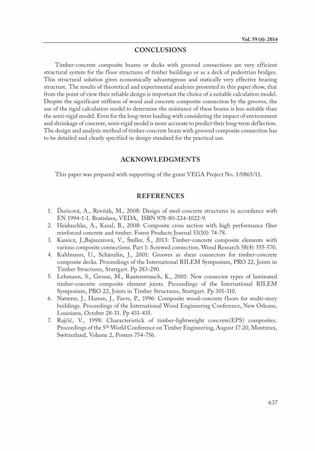
Fig. 13: Comparison of experimental and theoretical deflection.
- On the Fig. 13 comparison of average value of mid-span deflection of tested beams with theoretical calculated deflections in time with rigid and semi rigid composite connections is presented. The semi-rigid theoretical model better describes the real response of tested beams than the rigid model.
- Using the calculation model, the final deflection caused by permanent load was determined. Furthermore, final global creep coefficient value of experimental beam was possible to obtain. In the case of “semi-rigid” connection this value was 2.06 and in the case of "rigid" connection it was determined with value 2.31. This is due to the higher impact of shrinkage of concrete to the deflection of rigidly connected beam.
- Rigidity of composite connection has significant influence to the beam s response regarding to the environmental changes. Shrinkage of concrete in the groove may influence the rigidity of composite connection which leads to largest displacement of the composite beam.
637
Vol. 59 (4): 2014
CONCLUSIONS
Timber-concrete composite beams or decks with grooved connections are very efficient structural system for the f loor structures of timber buildings or as a deck of pedestrian bridges. This structural solution gives economically advantageous and statically very effective bearing structure. The results of theoretical and experimental analyzes presented in this paper show, that from the point of view their reliable design is important the choice of a suitable calculation model. Despite the significant stiffness of wood and concrete composite connection by the grooves, the use of the rigid calculation model to determine the resistance of these beams is less suitable than the semi-rigid model. Even for the long-term loading with considering the impact of environment and shrinkage of concrete, semi-rigid model is more accurate to predict their long-term deflection. The design and analysis method of timber-concrete beam with grooved composite connection has to be detailed and clearly specified in design standard for the practical use.
ACKNOWLEDGMENTS
This paper was prepared with supporting of the grant VEGA Project No. 1/0865/11.
REFERENCES
1. Ďuricová, A., Rovňák, M., 2008: Design of steel-concrete structures in accordance with EN 1994-1-1. Bratislava, VEDA, ISBN 978-80-224-1022-9.
2. Heiduschke, A., Kasal, B., 2008: Composite cross section with high performance fiber reinforced concrete and timber. Forest Products Journal 53(10): 74-78.
3. Kanócz, J.,Bajzecerová, V., Šteller, Š., 2013: Timber-concrete composite elements with various composite connections. Part 1: Screwed connection. Wood Research 58(4): 555-570.
4. Kuhlmann, U., Schänzlin, J., 2001: Grooves as shear connectors for timber-concrete composite decks. Proceedings of the International RILEM Symposium, PRO 22, Joints in Timber Structures, Stuttgart. Pp 283-290.
5. Lehmann, S., Grosse, M., Rautenstrauch, K., 2001: New connector types of laminated timber-concrete composite element joints. Proceedings of the International RILEM Symposium, PRO 22, Joints in Timber Structures, Stuttgart. Pp 301-310.
6. Natterer, J., Hamm, J., Favre, P., 1996: Composite wood-concrete f loors for multi-story buildings. Proceedings of the International Wood Engineering Conference, New Orleans, Louisiana, October 28-31. Pp 431-435.
7. Rajčič, V., 1998: Characteristick of timber-lightweight concrete(EPS) composites. Proceedings of the 5th World Conference on Timber Engineering, August 17-20, Montreux, Switzerland, Volume 2, Posters 754-756.
638
WOOD RESEARCH
Ján KanóczTechnical University of Košice
Faculty of ArtLetná 9
Sk-042 00 KošiceSlovak Republic
Corresponding author: [email protected]
Viktória BajzecerováTechnical University of KošiceFaculty of Civil Engineering
Vysokoškolská 4Sk-042 00 KošiceSlovak Republic
Štefan ŠtellerPulp and Paper Research Institute
Department Slovak Forest Product Research InstituteLamačská Cesta 3
Sk-841 04 BratislavaSlovak Republic
Related Documents