your position is our focus u-blox AG Zürcherstrasse 68 8800 Thalwil Switzerland www.u-blox.com Phone +41 44 2 7444 Fax +41 44 722 7447 [email protected] 72 TIM-5H u-blox 5 GPS/GALILEO Module Data Sheet Data Sheet Abstract Tec u-blox hnical data sheet describing the cost effective, high-performance 5 based TIM-5H GPS and GALILEO module. include A-GPS support, low power consumption, -160 dBm high tivity and an innovative jamming-resistant RF architecture. The hly successful TIM-4 series is maintained, enabling easy migration. The TIM-5H supports Features sensi 25.4 x 25.4 mm form factor of the hig passive and active antennas.

Welcome message from author
This document is posted to help you gain knowledge. Please leave a comment to let me know what you think about it! Share it to your friends and learn new things together.
Transcript

your position is our focus
u-blox AG Zürcherstrasse 68 8800 Thalwil Switzerland www.u-blox.com Phone +41 44 2 7444 Fax +41 44 722 7447 [email protected]
72
TIM-5H u-blox 5 GPS/GALILEO Module Data Sheet
Dat
a Sh
eet
Abstrac
t Tecu-blox
hnical data sheet describing the cost effective, high-performance 5 based TIM-5H GPS and GALILEO module.
include A-GPS support, low power consumption, -160 dBm hightivity and an innovative jamming-resistant RF architecture. The
hly successful TIM-4 series ismaintained, enabling easy migration. The TIM-5H supports
Featuressensi
25.4 x 25.4 mm form factor of the hig passive and
active antennas.

TIM-5H Data Sheet Preliminary u-blox proprietary
your position is our focus
Title TIM-5H
Subtitle u-blox 5 GPS/GALILEO Module
Doc Type Data Sheet Preliminary
Doc Id GPS.G5-MS5-07014-P3
Revision Index
Date Name Status / Comments
P1 15/05/2007 TG Preliminary
P2 24/07/ 2007 TG
P3 29/08/2007 TG KickStart, GPS Performance data
This document and the use of any information contained therein, is subject to the acceptance of the u-blox terms and conditions. They can be downloaded from www.u-blox.com.
u-blox reserves all rights to this document and the information contained herein. Reproduction, use or disclosure to third parties without express permission is strictly prohibited. Copyright © 2007, u-blox AG. For most recent documents, please visit www.u-blox.com
Data Sheet Revisions
Identification of applicable hardware Comments
- All data codes
Products marked with this lead-free symbol on the product label comply with the "Directive 2002/95/EC of the European Parliament and the Council on the Restriction of Use of certain Hazardous Substances in Electrical and Electronic Equipment" (RoHS).
This is an Electrostatic Sensitive Device (ESD).
Observe precautions for handling.
GPS.G5-MS5-07014-P3 Page 2

your position is our focus
1 Functional Description
1.1 Overview
The TIM-5H by u-blox sets a new standard for GPS and GALILEO receiver modules. Powered by the high performance 50-channel u-blox 5 technology, this module provides excellent performance and flexibility at an economical price. A 32-channel acquisition engine with over 1 million effective correlators is capable of massive parallel searches. This enables a Time To First Fix (TTFF) of less than 1 second, while long correlation/dwell times make possible an acquisition and tracking sensitivity of -160dBm. The TIM-5H includes KickStart, a new feature enabling accelerated acquisition of weak signals. Once acquired, satellites are passed on to a power-optimized dedicated tracking engine. This arrangement allows the GPS/GALILEO engine to simultaneously track up to 16 satellites while searching for new ones.
u-blox 5’s advanced jamming suppression mechanism and innovative RF architecture provides a high level of immunity to jamming, ensuring maximum GPS and GALILEO performance.
The TIM-5H is successor to the highly successful TIM-4 module series and shares the 25.4 x 25.4mm form factor. The built-in FLASH EPROM provides capacity to store user-specific configuration settings and allows for future updates.
The TIM-5H module is not designed for life saving or supporting devices or for aviation and should not be used in products that could in any way negatively impact the security or health of the user or third parties or that could cause damage to goods.
1.2 Highlights and Features
Highlights
• Time To First Fix (TTFF): < 1 sec • Acquisition and tracking sensitivity: -160dBm • Receives GPS and GALILEO signals • A-GPS: Supports u-blox AssistNow® Online and Offline • High immunity to jamming
Features
Vo
ltag
e R
ang
e (V
)
Thic
knes
s (m
m)
50-c
han
nel
en
gin
e
Kic
kSta
rt
Sup
erSe
nse
FW U
pd
ate
/
FLA
SH
UA
RT
USB
SPI
DD
C
Ass
istN
ow
®
On
line
Ass
istN
ow
®
Off
line
Dea
d R
ecko
nin
g
Raw
Dat
a
Prec
isio
n T
imin
g
1PPS
CFG
Pin
Res
et In
pu
t
An
ten
na
Su
pp
ly
An
ten
na
Su
per
viso
r
TIM-5H 2.7-3.6 3.0 2
Table 1: Features of the TIM-5H
TIM-5H Data Sheet Preliminary u-blox proprietary
GPS.G5-MS5-07014-P3 Page 3

your position is our focus
1.3 Block Diagram
RF Front-Endwith
Integrated LNA
Baseband Processor (UBX-G5000)
PowerManagement
TCXO or XTAL
RTC
FLASH EPROM
AntennaSupervision
Power Control
RF_IN
V_ANT
AADET_N
VCC_RF
VCC
V_BACKUP
GND
VCC_OUT
UART
EXTINT
RESET_N
SAFEBOOT
TIMEPULSE
DigitalIF Filter
BackupRAM
ROM Code
GPS/GALILEOEngine
ARM7 CPU
SRAM
SAWFilter
RTC
LDO
RESET_N
VDD
Figure 1: Hardware Block Schematic
1.4 Assisted GPS (A-GPS)
Supply of aiding information like ephemeris, almanac, rough last position and time and satellite status and an optional time synchronization signal will reduce time to first fix significantly and improve the acquisition sensitivity. The TIM-5H module supports the u-blox AssistNow Online® and AssistNow Offline® A-GPS service.
1.5 KickStart
A new feature available on the TIM-5H receiver module is SuperSense® KickStart. This functionality uses a TCXO to accelerate weak signal acquisition, enabling faster start and reacquisition times.
1.6 GALILEO
The u-blox 5 is a GNSS chip, that receives and tracks GPS and GALILEO signals simultaneously, enhancing accuracy and coverage. When GALILEO-L1 signals become available, u-blox 5 receivers will be capable of receiving and processing them via a simple upgrade. The ability to receive and track GALILEO satellite signals will result in higher coverage, improved reliability and better accuracy.
1.7 Protocols
Protocol Type
NMEA Input/output, ASCII, 0183, 2.3 (compatible to 3.0) UBX Input/output, binary, u-blox proprietary
Table 2: Available Protocols
Both protocols are available on UART. For specification of the various protocols see the u-blox 5 Protocol Specification [2].
TIM-5H Data Sheet Preliminary u-blox proprietary
GPS.G5-MS5-07014-P3 Page 4

your position is our focus
1.8 Antenna
The TIM-5H module is designed for use with passive and active antennas. An antenna supervisor is provided on all modules. In the default operation mode the antenna supervisor is activated and enables the receiver to detect short circuits to the active antenna by checking the bias voltage level and can shut down the voltage bias immediately. A series resistor is needed in front of the V_ANT input. UBX and NMEA messages are provided to report the condition of the antenna supply. Open circuit detection can also be supported with an additional external circuit. For details, please refer to the TIM-5H Hardware Integration Manual [1].
Parameter Specification
Antenna Type Passive and active antenna
Active Antenna Recommendations
Minimum gain
Maximum noise figure
Maximum gain
15 - 20 dB (to compensate signal loss in RF cable)
1.5 dB
30 dB
Table 3: Antenna Specifications for TIM-5H Module
Parameter Specification
Antenna Supply Using VCC_RF or external voltage source
Antenna Supervisor Short circuit detection
Open circuit detection
Built-in
Enabled with external circuit
Table 4: Antenna Supervisor Specifications
1.9 Configuration
With the TIM-5H the configuration settings can be modified with UBX configuration messages. The modifications can be permanently saved to the FLASH memory.
For more information see the TIM-5H Hardware Integration Manual [1].
TIM-5H Data Sheet Preliminary u-blox proprietary
GPS.G5-MS5-07014-P3 Page 5

your position is our focus
2 GPS Performance
Parameter Specification
Receiver Type 50 Channels GPS L1 frequency, C/A Code GALILEO Open Service L1 frequency
Cold Start (Autonomous) 29 s Warm Start (Autonomous) 29 s Hot Start (Autonomous) <1 s
Time-To-First-Fix1
Aided Starts2 <1 s Tracking & Navigation -160 dBm Acquisition -160 dBm Sensitivity Cold Start (Autonomous) -145 dBm Autonomous < 2.5 m
Horizontal Position Accuracy3
SBAS < 2.0 m Accuracy of Timepulse Signal RMS 50 ns Max Navigation Update Rate 4 Hz
Dynamics ≤ 4 g Operational Limits Velocity 515 m/s (1000 knots)
Table 5: TIM-5H GPS Performance
1 All satellites at –130 dB 2 Dependent on aiding data connection speed and latency 3 CEP, 50%, 24 hours static, -130dBm
TIM-5H Data Sheet Preliminary u-blox proprietary
GPS.G5-MS5-07014-P3 Page 6
your position is our focus
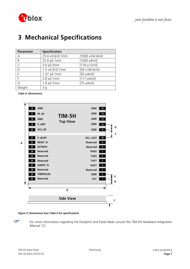
3 Mechanical Specifications Parameter Specification A 25.4 +0.6/-0.1mm [1000 +24/-4mil] B 25.4 ±0.1mm [1000 ±4mil] C 3.0 ±0.3mm [118 ±12mil] D 1.5 +0.3/-0.1mm [59 +18/-4mil] E 1.27 ±0.1mm [50 ±4mil] F 2.8 ±0.1mm [111 ±4mil] G 1.9 ±0.1mm [75 ±4mil] Weight 3 g
Table 6: Dimensions
TIM-5HTop View
GND
RF_IN
GND
V_ANT
VCC_RF
V_BCKP
RESET_N
EXTINT0
Reserved
Reserved
AADET_N
Reserved
Reserved
TIMEPULSE
Reserved
16 15
17 14
18
19
20
30
29
28
27
26
25
24
23
22
21
13
12
11
1
2
3
4
5
6
7
8
9
10VCC_OUT
Reserved
Reserved
RxD2
TxD2
TxD1
RxD1
Reserved
GND
VCC
GND
GND
GND
GND
GND
B
A
G
F
E
D
CSide View
Figure 2: Dimensions (see Table 6 for specification)
For more information regarding the Footprint and Paste Mask consult the TIM-5H Hardware Integration Manual [1].
TIM-5H Data Sheet Preliminary u-blox proprietary
GPS.G5-MS5-07014-P3 Page 7

your position is our focus
3.1 Pin Assignment
No Name I/O Description 1 VCC I Supply voltage
2 GND I Ground
3 Reserved I Reserved
4 RxD1 I Serial Port 1
5 TxD1 O Serial Port 1
6 TxD2 O Serial Port 2
7 RxD2 I Serial Port 2
8 Reserved I Reserved
9 Reserved I Reserved
10 VCC_OUT O Output Voltage
11-16
GND I Ground
17 RF_IN I GPS/GALILEO signal input
18 GND I Ground
19 V_ANT I Antenna Bias voltage
20 VCC_RF O Output Voltage RF section
21 V_BCKP I Backup Voltage Supply
22 RESET_N I/O Reset (Active low)
23 EXTINT0 I External Interrupt Pin
24 Reserved I Reserved
25 Reserved I Reserved
26 Reserved I Reserved
27 AADET_N I Active Antenna Detect
28 Reserved I Reserved
29 TIMEPULSE O Timepulse signal
30 Reserved I Reserved
Table 8: Pinout
Pins designated Reserved should only be used with caution. For more information about Pinouts see the TIM-5H Hardware Integration Manual [1].
TIM-5H Data Sheet Preliminary u-blox proprietary
GPS.G5-MS5-07014-P3 Page 8

your position is our focus
4 Electrical Specifications
4.1 Absolute Maximum Ratings
Parameter Symbol Min Max Units
Power supply voltage (VCC) Vcc -0.5 3.6 V
Backup battery voltage (V_BCKP) p Vbck -0.5 4.8 V
Input pin voltage Vin -0.5 Vcc +0.5 V
VCC_RF output current 0 Iccrf 10 mA
Antenna bias voltage Vant 6 V
Antenna bias current4 Iant 100 mA
Storage temperature Tstg -40 85 °C
Table 9: Absolute Maximum Ratings
be limited to values within the specified boundaries by using appropriate protection diodes.
Stressing the device beyond the “Absolute Maximum Ratings” may cause permanent damage. These are stress ratings only. The product is not protected against overvoltage or reversed voltages. If necessary, voltage spikes exceeding the power supply voltage specification, given in table above, must
4 Applied via V_ANT
TIM-5H Data Sheet Preliminary u-blox proprietary
GPS.G5-MS5-07014-P3 Page 9

your position is our focus
4.2 Operating Conditions Parameter5
Symbol Min Typ Max Units Condition Power supply voltage (VCC) Vcc 2.7 3.6 V Sustained supply current 6 Icc 40 mA Vcc = 3.0 V Peak supply current 7 Iccp 150 mA Vcc = 3.6 V Backup battery voltage Vbckp 1.3 4.8 V Backup battery current Ibckp 30 μA Vbckp = 3.3V Input pin voltage range Vin Vcc +0.5 V Input pin low voltage Vin_low_1 0.2x Vcc V Input pin high voltage Vin_high_1 0.7x Vcc V Input pin low voltage for EXTINT0 and RxD1
Vin_low_2 0.22 V
Input pin high voltage for EXTINT0 and RxD1
Vin_high_2 0.91 V
Output pin voltage range Vout V Output pin low voltage Vout_low 0.4 V Iout = 4 mA Output pin high voltage Vout_high Vcc-0.4 V Iout = -4 mA Antenna gain Gant 30 dB V_ANT antenna bias voltage Vant 2.7 5.5 V IANT <- 20 mA Antenna bias voltage drop Vant_drop 0.1 Iccrf=50mA VCC_RF voltage Vccrf Vcc-0.1 V VCC_RF output current Iccrf 50 mA Operating temperature Topr -40 85 °C
Table 10: Operating Conditions
Operation beyond the "Operating Conditions" is not recommended and extended exposure beyond the "Operating Conditions" may affect device reliability.
5 All specification are at an ambient temperature of 25°C. 6 Average current drawn during Continuous Tracking Mode with 1 Hz update rate, using 9 channels for tracking and navigation and 3 channels for searching satellites (= acquisition). Use this figure to determine required battery capacity.
7 Peak current drawn during initial acquisition phase. Use this figure to dimension maximum current capability of power supply.
TIM-5H Data Sheet Preliminary u-blox proprietary
GPS.G5-MS5-07014-P3 Page 10

your position is our focus
5 Environmental Specifications Detailed description of the test series:
Test Standard
Visual inspection IPC-A-610 “Acceptability of electronic assemblies” I.T.R.I. Publication No. 700 IPC-SM-840B Class 2.
Thermal shock -40°C...+125°C, 100 cycles IEC 68-2-14 -40°C/2 hours; RT/2 hours; IEC 68-2-1 and IEC 68-2-2 Function at
various temperatures
+85°C/2 hours; function tests at stable temperature
Lifespan test +85°C/1000 hours, in function IEC 68-2-2 Damp heat, cyclic +25°C...+55°C; >90% Rh IEC 68-2-30 Vibration 10-500 Hz; 2 hours/axis; 5g IEC 68-2-6 Shock 30g/11ms (halfsine); 3 Shock/axis; no
function IEC 68-2-27
Metallographic investigations
IPC-QE-650
Table 11: Environmental Specification
This specification is preliminary and subject to confirmation.
6 Design-In In order to obtain the necessary information to conduct a proper design-in, u-blox strongly recommends consulting the TIM-5H Hardware Integration Manual [1].
TIM-5H Data Sheet Preliminary u-blox proprietary
GPS.G5-MS5-07014-P3 Page 11
your position is our focus
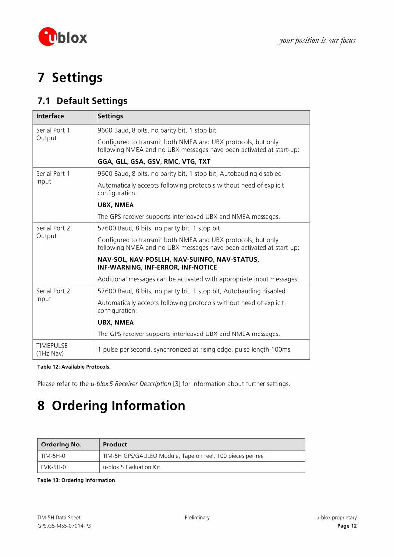
7 Settings
7.1 Default Settings
Interface Settings
Serial Port 1 Output
9600 Baud, 8 bits, no parity bit, 1 stop bit
Configured to transmit both NMEA and UBX protocols, but only following NMEA and no UBX messages have been activated at start-up:
GGA, GLL, GSA, GSV, RMC, VTG, TXT
Serial Port 1 Input
9600 Baud, 8 bits, no parity bit, 1 stop bit, Autobauding disabled
Automatically accepts following protocols without need of explicit configuration:
UBX, NMEA
The GPS receiver supports interleaved UBX and NMEA messages.
Serial Port 2 Output
57600 Baud, 8 bits, no parity bit, 1 stop bit
Configured to transmit both NMEA and UBX protocols, but only following NMEA and no UBX messages have been activated at start-up:
NAV-SOL, NAV-POSLLH, NAV-SUINFO, NAV-STATUS, INF-WARNING, INF-ERROR, INF-NOTICE
Additional messages can be activated with appropriate input messages.
Serial Port 2 Input
57600 Baud, 8 bits, no parity bit, 1 stop bit, Autobauding disabled
Automatically accepts following protocols without need of explicit configuration:
UBX, NMEA
The GPS receiver supports interleaved UBX and NMEA messages.
TIMEPULSE (1Hz Nav)
1 pulse per second, synchronized at rising edge, pulse length 100ms
Table 12: Available Protocols.
Please refer to the u-blox 5 Receiver Description [3] for information about further settings.
8 Ordering Information
Ordering No. Product
TIM-5H-0 TIM-5H GPS/GALILEO Module, Tape on reel, 100 pieces per reel
EVK-5H-0 u-blox 5 Evaluation Kit
Table 13: Ordering Information
TIM-5H Data Sheet Preliminary u-blox proprietary
GPS.G5-MS5-07014-P3 Page 12

TIM-5H Data Sheet Preliminary u-blox proprietary
your position is our focus
Related Documents [1] TIM-5H Hardware Integration Manual, Docu. No GPS.G5-MS5-07015
[2] u-blox 5 Protocol Specification, Docu. No GPS-X-07006
[3] u-blox 5 Receiver Description, Docu. No GPS.G5-X-07018
All these documents are available on our website (www.u-blox.com).
For regular updates to u-blox documentation and to receive product change notifications please register on our homepage.
GPS.G5-MS5-07014-P3 Page 13

TIM-5H Data Sheet Preliminary u-blox proprietary
GPS.G5-MS5-07014-P3 Page 14
your position is our focus
Contact For further info, please contact us:
Headquarters
u-blox AG Zuercherstrasse 68 CH-8800 Thalwil Switzerland
Phone: +41 44 722 74 44 Fax: +41 44 722 74 47 E-mail: [email protected]
www.u-blox.com
Sales Offices
North, Central and South America
u-blox America, Inc. 1902 Campus Commons Drive Suite 310 Reston, VA 20191 USA
Phone: +1 (703) 483 3180 Fax: +1 (703) 483 3179 E-mail: [email protected]
Regional Office West Coast: 8600 Lemon Ave #1 La Mesa, CA 91941 USA
Phone: +1 (619) 741 3011 Fax: +1 (619) 741 4334 E-mail: [email protected]
Technical Support:
Phone: +1 (703) 483 3185 E-mail: [email protected]
Europe, Middle East, Africa
u-blox AG Zuercherstrasse 68 CH-8800 Thalwil Switzerland
Phone: +41 44 722 74 44 Fax: +41 44 722 74 47 E-mail: [email protected]
Technical Support:
Phone: +41 44 722 74 74 E-mail: [email protected]
Asia, Australia, Pacific
u-blox Singapore Pte. Ltd. 435 Orchard Road #19-02, Wisma Atria, Singapore 238877
Phone: +65 6734 3811 Fax: +65 6736 1533 E-mail: [email protected] Support: [email protected]
Regional Office China:
Room 716-718 No. 65 Fuxing Road Beijing, 100036, China
Phone: +86 10 68 133 545 Fax: +86 10 68 217 890 E-mail: [email protected] Support: [email protected]
Regional Office Korea: Room 501, Gyeong Hui Building 109-18, Samseong-Dong, GangNam-Gu, Seoul, Korea 135-090
Phone: +82 2 542 0861 Fax: +82 2 542 0862 E-mail: [email protected] Support: +82 31 383 2584 [email protected]
Regional Office Taiwan:
Room 305 3F, #181, ZouTze Street Neihu Dis. Taipei, Taiwan
Phone: +886 2 2657 1090 Fax: +886 2 2657 1097 E-mail: [email protected] Support: [email protected]
Related Documents


