1 Table of Contents Page Introduction Please read this USER’S MANUAL carefully. It will show you how to assemble, maintain and operate this Consumer: Retain these instructions for future reference. Unpacking Specifications 1.Remove all packing items applied to heater for shipment. 2.Remove all items from carton. 3.Check all items for shipping damage. If heater is damaged, promptly inform dealer where you purchased heater. Tiger-King Portable Air Forced Heaters Operating Instructions & Parts Manual TK12000, TK20000, TK30000, TK50000, TK70000 Please read and save these instructions. Read carefully before attempting to assemble, install, operate or maintain the product described. Protect yourself and others by observing all safety information. Failure to comply with instructions could result in personal injury and/or property damage! Retain instructions for future reference. Description TigerKing Models TK12000, TK20000, TK30000, TK50000,TK70000 heaters are 20,000 to 70,000 kCal/Hr heaters. These heaters use 1-K Kerosene (see Operation section for alternative fuels) for combustion, and electricity to run the fan. It is primarily intended for temporary heating of well ventilated buildings under construction, alteration, or repair. This heater may be used in agricultural, industrial and com- mercial environments. -ELECTRICAL SPECIFICATIONS Electrical Input Model Amperage Fuse Spark Plug Gap -GENERAL SPECIFICATIONS Type of Fuel Pump Fuel Tank Fuel Model Input Rating Pressure Capacity Consumption L x W x H (mm) (kg) Figure 1 – Models TK12000 Models TK20000 Figure2 –Models TK30000, TK50000,70000 Size Weight TK20000 220V, 60/50Hz 1. 4 220V/5 amp .140"(3.5mm) TK12000 220V, 60/50Hz 1. 4 220V/5 amp .140"(3.5mm) TK30000 220V, 60/50Hz 1. 5 220V/5 amp .140"(3.5mm) TK50000 220V, 60/50Hz 2. 3 220V/5 amp .140"(3.5mm) TK70000 220V, 60/50Hz 3 220V/5 amp .140"(3.5mm) TK20000 Kerosene/Diedel 2. 1 l/h TK12000 Kerosene/Diedel 1. 3 l/h TK30000 Kerosene/Diedel 3. 6 l/h l/h TK50000 Kerosene/Diedel 5. 0 TK70000 Kerosene/Diedel 6. 0 l/h Description Specifications introduction Unpacking Product Features General Safety Information Assembly 1 1 1 1 2 2-3 4-5 Kerosene(1-K or No. 1 Fuel Oil) Operation Overview of Heater Design Fueling Your Heater Ventilation Long-Term Storage Maintenance 5-6 5-8 6 6 7 7-8 8-11 Wiring Diagrams Repair Parts Illustration Models Tk20000 and TK30000 Repair Parts Illustration Models TK50000 and TK70000 Repair Parts Illustration Models TK100000 Troubleshooting Chart 12 13 14 15 16-17 11,250Kcal/hr 18,750Kcal/hr 31,250Kcal/hr 43,750Kcal/hr 52,500Kcal/hr 20Liter 20Liter 40Liter 50LIter 50Liter 740X300X405 740X300X405 980X545X670 1020X590X635 1020X590X635 12.7kg 12.8kg 24.4kg 27.2kg 28.2kg 3.3 PSI 3.2 PSI 5.2 PSI 6.0 PSI 7.0 PSI

Welcome message from author
This document is posted to help you gain knowledge. Please leave a comment to let me know what you think about it! Share it to your friends and learn new things together.
Transcript
1
Table of Contents Page
IntroductionPlease read this USER’S MANUALcarefully. It will show you how toassemble, maintain and operate this
Consumer: Retain these instructions
for future reference.
Unpacking
Specifications
1.Remove all packing items applied toheater for shipment.
2.Remove all items from carton.
3.Check all items for shipping damage.If heater is damaged, promptlyinform dealer where you purchasedheater.
Tiger-King Portable Air Forced Heaters
Operating Instructions & Parts Manual TK12000, TK20000, TK30000, TK50000, TK70000
Please read and save these instructions. Read carefully before attempting to assemble, install, operate or maintain the product described.Protect yourself and others by observing all safety information. Failure to comply with instructions could result in personal injury and/orproperty damage! Retain instructions for future reference.
DescriptionTigerKing Models TK12000, TK20000, TK30000, TK50000,TK70000 heaters are 20,000to 70,000 kCal/Hr heaters. These heaters use 1-K Kerosene (see Operation section for alternative fuels) for combustion, and electricity to run the fan. It is primarilyintended for temporary heating of well ventilated buildings under construction,alteration, or repair. This heater may be used in agricultural, industrial and com-mercial environments.
-ELECTRICAL SPECIFICATIONS
Electrical InputModel Amperage Fuse Spark Plug Gap
-GENERAL SPECIFICATIONS
Type of FuelPump Fuel Tank Fuel
Model Input Rating Pressure Capacity Consumption L x W x H (mm) (kg)
Figure 1 – Models TK12000
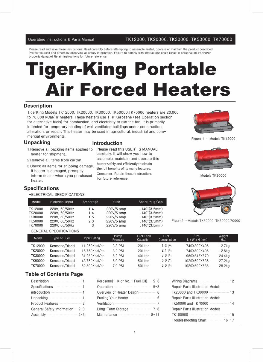
Models TK20000
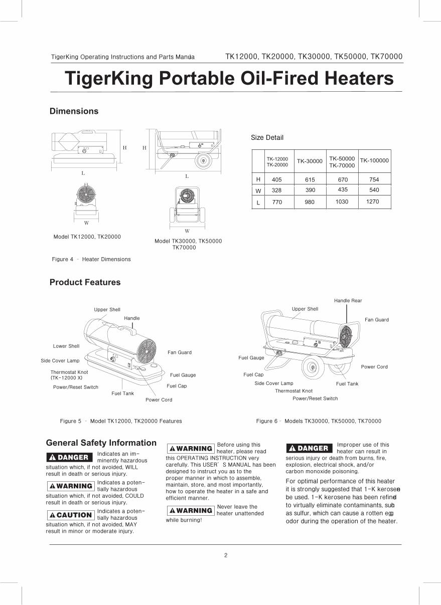
Figure2 –Models TK30000, TK50000,70000
Size Weight
TK20000 220V, 60/50Hz 1.4 220V/5 amp .140"(3.5mm)TK12000 220V, 60/50Hz 1.4 220V/5 amp .140"(3.5mm)
TK30000 220V, 60/50Hz 1.5 220V/5 amp .140"(3.5mm)TK50000 220V, 60/50Hz 2.3 220V/5 amp .140"(3.5mm)TK70000 220V, 60/50Hz 3 220V/5 amp .140"(3.5mm)
TK20000 Kerosene/Diedel 2.1 l/hTK12000 Kerosene/Diedel 1.3 l/h
TK30000 Kerosene/Diedel 3.6 l/hl/hTK50000 Kerosene/Diedel 5.0
TK70000 Kerosene/Diedel 6.0 l/h
Description
Specifications
introduction
Unpacking
Product Features
General Safety Information
Assembly
1
1
1
1
2
2-3
4-5
Kerosene(1-K or No. 1 Fuel Oil)
Operation
Overview of Heater Design
Fueling Your Heater
Ventilation
Long-Term Storage
Maintenance
5-6
5-8
6
6
7
7-8
8-11
Wiring Diagrams
Repair Parts Illustration Models
Tk20000 and TK30000
Repair Parts Illustration Models
TK50000 and TK70000
Repair Parts Illustration Models
TK100000
Troubleshooting Chart
12
13
14
15
16-17
11,250Kcal/hr18,750Kcal/hr31,250Kcal/hr43,750Kcal/hr52,500Kcal/hr
20Liter20Liter40Liter50LIter50Liter
740X300X405740X300X405980X545X670
1020X590X6351020X590X635
12.7kg12.8kg24.4kg27.2kg28.2kg
3.3 PSI3.2 PSI5.2 PSI6.0 PSI7.0 PSI
2
TigerKing Operating Instructions and Parts Manual TK12000, TK20000, TK30000, TK50000, TK70000
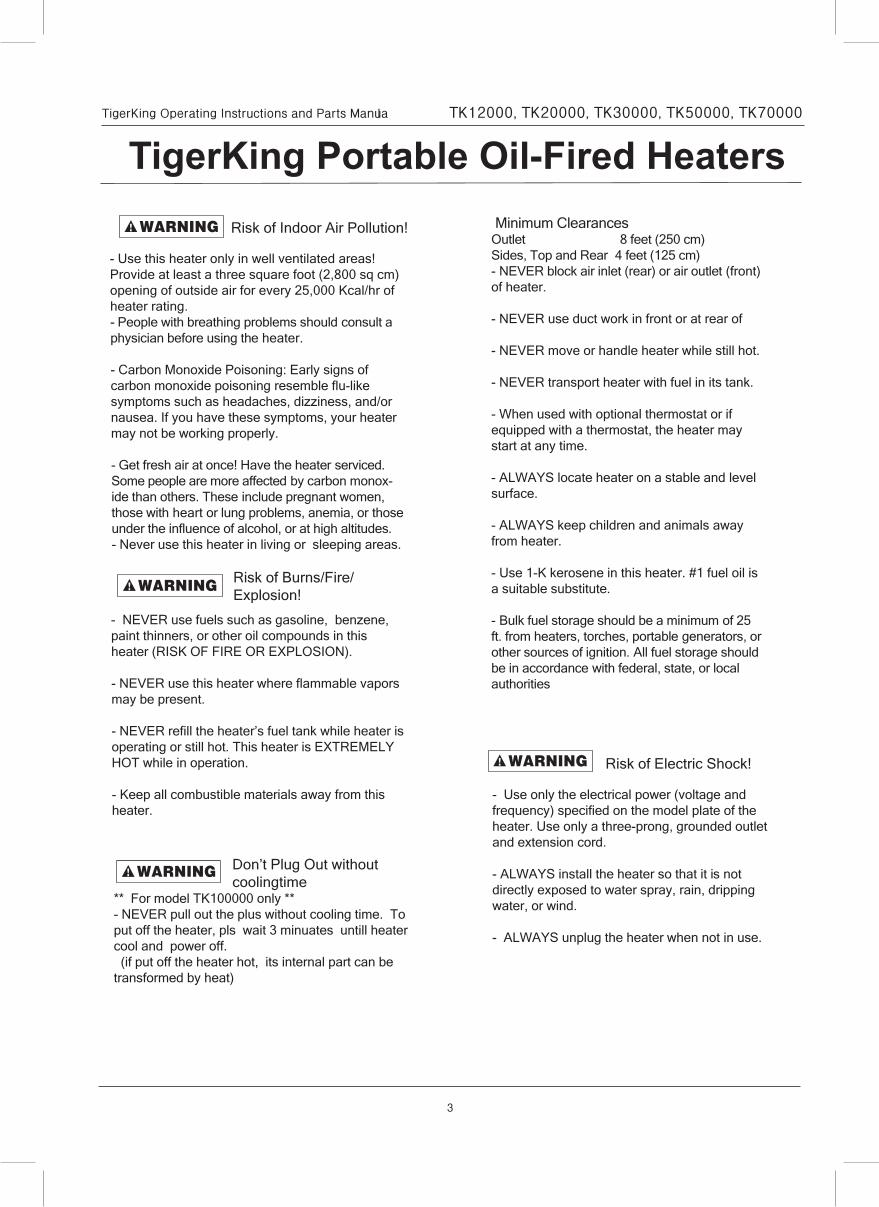
Figure 5 – Model TK12000, TK20000 Features Figure 6– Models TK30000, TK50000, TK70000
Model TK12000, TK20000Model TK30000, TK50000 TK70000
Figure 4 – Heater Dimensions
General Safety InformationIndicates an im-minently hazardous
situation which, if not avoided, WILLresult in death or serious injury.
Indicates a poten-tially hazardous
situation which, if not avoided, COULDresult in death or serious injury.
Indicates a poten-tially hazardous
situation which, if not avoided, MAYresult in minor or moderate injury.
Before using thisheater, please read
this OPERATING INSTRUCTION verycarefully. This USER’S MANUAL has beendesigned to instruct you as to theproper manner in which to assemble,maintain, store, and most importantly,how to operate the heater in a safe andefficient manner.
Never leave theheater unattended
while burning!
Improper use of thisheater can result in
serious injury or death from burns, fire,explosion, electrical shock, and/orcarbon monoxide poisoning.
For optimal performance of this heater,it is strongly suggested that 1-K kerosenebe used. 1-K kerosene has been refinedto virtually eliminate contaminants, suchas sulfur, which can cause a rotten eggodor during the operation of the heater.
TigerKing Portable Oil-Fired HeatersDimensions
Product Features
H
L
W
H
L
W
Upper Shell
Handle Rear
Fan Guard
Fuel Gauge
Fuel Cap
Side Cover Lamp
Thermostat Knot
Power/Reset Switch
Fuel Tank
Power Cord
Upper Shell
Fan Guard
Fuel Gauge
Fuel Cap
Lower Shell
Side Cover Lamp
Thermostat Knot(TK-12000 X)
Power/Reset Switch Fuel Tank
Power Cord
Handle
3
TigerKing Operating Instructions and Parts Manual TK12000, TK20000, TK30000, TK50000, TK70000
TigerKing Portable Oil-Fired Heaters
- Use this heater only in well ventilated areas! Provide at least a three square foot (2,800 sq cm) opening of outside air for every 25,000 Kcal/hr of heater rating.- People with breathing problems should consult a physician before using the heater.
- Carbon Monoxide Poisoning: Early signs of carbon monoxide poisoning resemble flu-like symptoms such as headaches, dizziness, and/or nausea. If you have these symptoms, your heater may not be working properly.
- Get fresh air at once! Have the heater serviced. Some people are more affected by carbon monox-ide than others. These include pregnant women, those with heart or lung problems, anemia, or those under the influence of alcohol, or at high altitudes.- Never use this heater in living or sleeping areas.
Risk of Indoor Air Pollution!
Risk of Burns/Fire/ Explosion!
- NEVER use fuels such as gasoline, benzene, paint thinners, or other oil compounds in this heater (RISK OF FIRE OR EXPLOSION).
- NEVER use this heater where flammable vapors may be present.
- NEVER refill the heater’s fuel tank while heater is operating or still hot. This heater is EXTREMELY HOT while in operation.
- Keep all combustible materials away from this heater.
Don’t Plug Out without coolingtime
** For model TK100000 only ** - NEVER pull out the plus without cooling time. To put off the heater, pls wait 3 minuates untill heater cool and power off. (if put off the heater hot, its internal part can be transformed by heat)
Minimum ClearancesOutlet 8 feet (250 cm)Sides, Top and Rear 4 feet (125 cm)- NEVER block air inlet (rear) or air outlet (front) of heater.
- NEVER use duct work in front or at rear of
- NEVER move or handle heater while still hot.
- NEVER transport heater with fuel in its tank.
- When used with optional thermostat or if equipped with a thermostat, the heater may start at any time.
- ALWAYS locate heater on a stable and level surface.
- ALWAYS keep children and animals away from heater.
- Use 1-K kerosene in this heater. #1 fuel oil is a suitable substitute.
- Bulk fuel storage should be a minimum of 25 ft. from heaters, torches, portable generators, or other sources of ignition. All fuel storage should be in accordance with federal, state, or local authorities
- Use only the electrical power (voltage and frequency) specified on the model plate of the heater. Use only a three-prong, grounded outlet and extension cord.
- ALWAYS install the heater so that it is not directly exposed to water spray, rain, dripping water, or wind.
- ALWAYS unplug the heater when not in use.
Risk of Electric Shock!
4
TigerKing Operating Instructions and Parts Manual TK12000, TK20000, TK30000, TK50000, TK70000
TigerKing Portable Oil-Fired Heaters
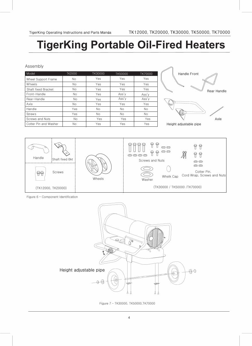
Assembly
Model TK20000 TK30000
Wheel Support Frame
seYseYseY
seY
oNsleehW
seYseYoN
Front-Handle No
Rear-Handle No
seYseYseYoNelxA
oNoNoNseYeldnaH
oNoNoNseYswercS
Screws and Nuts No Yes Yes Yes
Cotter Pin and Washer No Yes Yes Yes
Handle
Wheels Washer
Screws and Nuts
Cotter Pin,
Whelk Cap Cord Wrap, Screws and Nuts
(TK30000 / TK50000 /TK70000)
Screws
(TK12000, TK20000)
Figure 6 – Component Identification
Handle Front
Rear Handle
Axle
Height adjustable pipe
TK50000 TK70000
Yes
No Yes Yes Yes
Yes
Ass’y
Ass’y
Ass’y
Ass’y
Shaft fixed Bracket
Shaft fixed Bkt
Figure 7 – TK30000, TK50000,TK70000
Height adjustable pipe
5
TigerKing Operating Instructions and Parts Manual TK12000, TK20000, TK30000, TK50000, TK70000
TigerKing Portable Oil-Fired Heaters
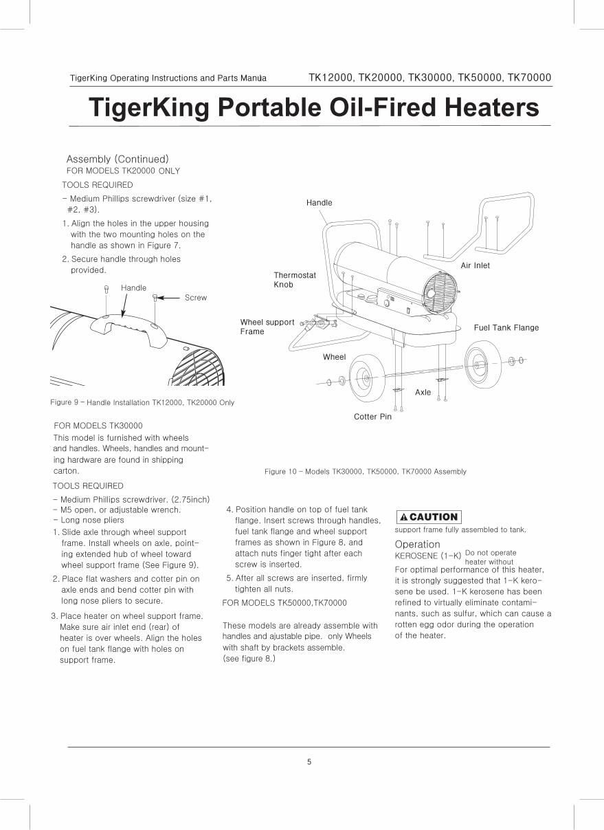
Assembly (Continued)FOR MODELS TK20000 ONLY
TOOLS REQUIRED
- Medium Phillips screwdriver (size #1,
#2, #3).
1. Align the holes in the upper housing
with the two mounting holes on the
handle as shown in Figure 7.
2. Secure handle through holes
provided.
FOR MODELS TK30000
This model is furnished with wheels
and handles. Wheels, handles and mount-
ing hardware are found in shipping
carton.
TOOLS REQUIRED
- Medium Phillips screwdriver. (2.75inch)- M5 open, or adjustable wrench.- Long nose pliers
1. Slide axle through wheel support
frame. Install wheels on axle, point-
ing extended hub of wheel toward
wheel support frame (See Figure 9).
2. Place flat washers and cotter pin on
axle ends and bend cotter pin with
long nose pliers to secure.
3. Place heater on wheel support frame.
Make sure air inlet end (rear) of
heater is over wheels. Align the holes
on fuel tank flange with holes on
support frame.
4. Position handle on top of fuel tank
flange. Insert screws through handles,
fuel tank flange and wheel support
frames as shown in Figure 8, and
attach nuts finger tight after each
screw is inserted.
5. After all screws are inserted, firmly
tighten all nuts.
Do not operateheater without
support frame fully assembled to tank.
OperationKEROSENE (1-K)
For optimal performance of this heater,
it is strongly suggested that 1-K kero-
sene be used. 1-K kerosene has been
refined to virtually eliminate contami-
nants, such as sulfur, which can cause a
rotten egg odor during the operation
of the heater.
Figure 9 – Handle Installation TK12000, TK20000 Only
Figure 10 – Models TK30000, TK50000, TK70000 Assembly
FOR MODELS TK50000,TK70000
These models are already assemble with
handles and ajustable pipe. only Wheels
with shaft by brackets assemble.
(see figure 8.)
ScrewHandle
Handle
Air Inlet
Fuel Tank Flange
Axle
Wheel
Cotter Pin
Wheel supportFrame
ThermostatKnob
6
TigerKing Operating Instructions and Parts Manual TK12000, TK20000, TK30000, TK50000, TK70000
TigerKing Portable Oil-Fired Heaters
Operation (Continued)Be advised that these fuels do not burn
as clean as 1-K kerosene, and care
should be taken to provide more fresh
air ventilation to accommodate any
added contaminants that may be added
to the heated space.
NOTE: Kerosene should only be stored
in a blue container that is clearly
marked “kerosene”. Never store kero-
sene in a red container. Red is associ-
ated with gasoline.
- NEVER store kerosene in the living
space. Kerosene should be stored in a
well ventilated area outside the living
area.
- NEVER use fuel such as gasoline,
benzene, alcohol, white gas, camp
stove fuel, paint thinners, or other oil
compounds in this heater (THESE ARE
VOLATILE FUELS THAT CAN CAUSE A
FIRE OR EXPLOSION).
- NEVER store kerosene in direct
sunlight or near a source of heat.
- NEVER use kerosene that has been
stored from one season to the next.
Kerosene deteriorates over time. OLD
KEROSENE WILL NOT BURN PROPERLY
IN THIS HEATER.
- Use 1-K kerosene in this heater. #1 fuel
is a suitable substitute.
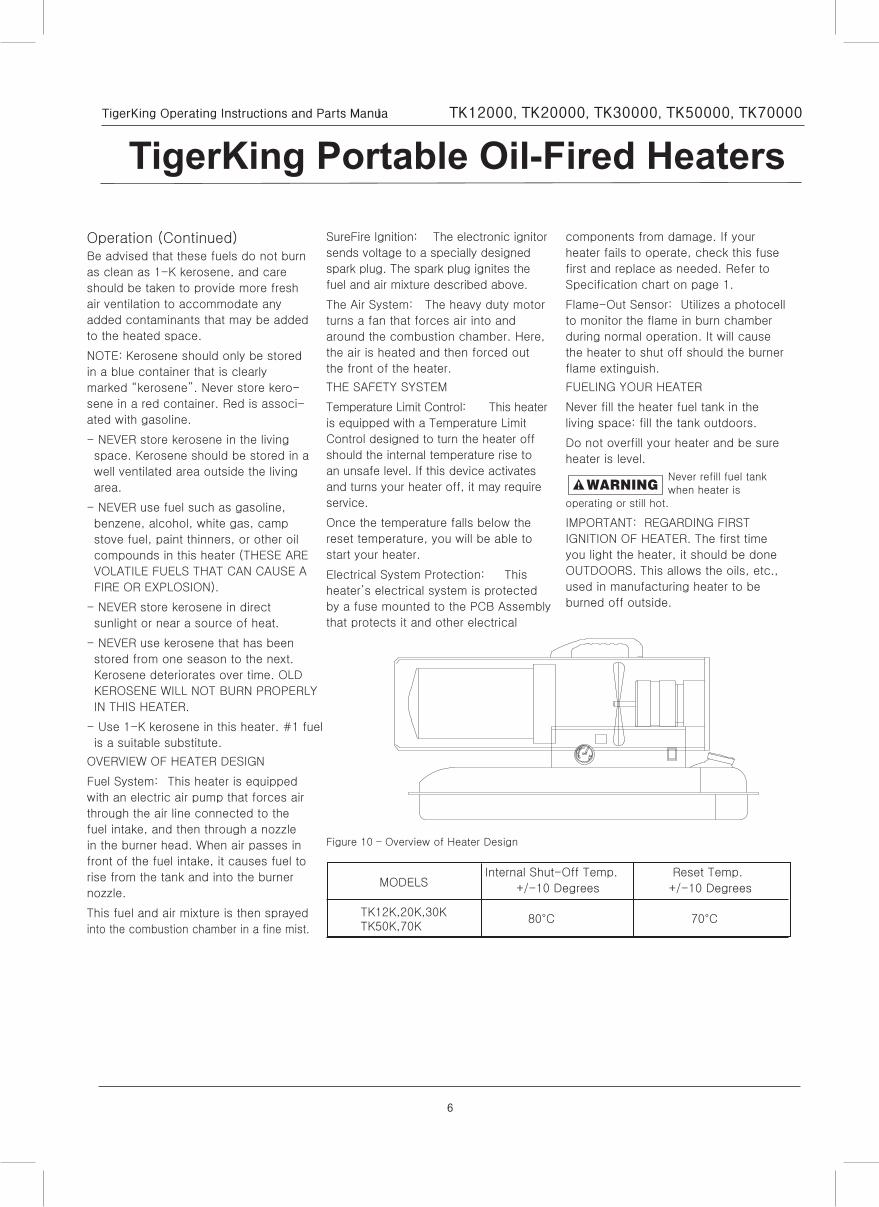
OVERVIEW OF HEATER DESIGN
Fuel System: This heater is equipped
with an electric air pump that forces air
through the air line connected to the
fuel intake, and then through a nozzle
in the burner head. When air passes in
front of the fuel intake, it causes fuel to
rise from the tank and into the burner
nozzle.
This fuel and air mixture is then sprayed
into the combustion chamber in a fine mist.
SureFire Ignition: The electronic ignitor
sends voltage to a specially designed
spark plug. The spark plug ignites the
fuel and air mixture described above.
The Air System: The heavy duty motor
turns a fan that forces air into and
around the combustion chamber. Here,
the air is heated and then forced out
the front of the heater.
THE SAFETY SYSTEM
Temperature Limit Control: This heater
is equipped with a Temperature Limit
Control designed to turn the heater off
should the internal temperature rise to
an unsafe level. If this device activates
and turns your heater off, it may require
service.
Once the temperature falls below the
reset temperature, you will be able to
start your heater.
Electrical System Protection: This
heater’s electrical system is protected
by a fuse mounted to the PCB Assembly
that protects it and other electrical
components from damage. If your
heater fails to operate, check this fuse
first and replace as needed. Refer to
Specification chart on page 1.
Flame-Out Sensor: Utilizes a photocell
to monitor the flame in burn chamber
during normal operation. It will cause
the heater to shut off should the burner
flame extinguish.
FUELING YOUR HEATER
Never fill the heater fuel tank in the
living space: fill the tank outdoors.
Do not overfill your heater and be sure
heater is level.
Never refill fuel tankwhen heater is
operating or still hot.
IMPORTANT: REGARDING FIRST
IGNITION OF HEATER. The first time
you light the heater, it should be done
OUTDOORS. This allows the oils, etc.,
used in manufacturing heater to be
burned off outside.
MODELS
TK12K,20K,30KTK50K,70K
Internal Shut-Off Temp.
+/-10 Degrees
80°C
Reset Temp.
+/-10 Degrees
70°C
Figure 10 – Overview of Heater Design
7
TigerKing Operating Instructions and Parts Manual TK12000, TK20000, TK30000, TK50000, TK70000
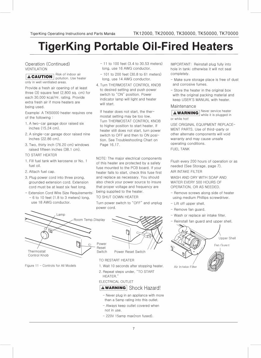
TigerKing Portable Oil-Fired HeatersOperation (Continued)VENTILATION
Risk of indoor airpollution. Use heater
only in well ventilated areas.
Provide a fresh air opening of at least
three (3) square feet (2,800 sq. cm) for
each 30,000 kcal/Hr. rating. Provide
extra fresh air if more heaters are
being used.
Example: A TK50000 heater requires one
of the following :
1. A two-car garage door raised six
inches (15.24 cm).
2. A single-car garage door raised nine
inches (22.86 cm).
3. Two, thirty inch (76.20 cm) windows
raised fifteen inches (38.1 cm).
TO START HEATER
1. Fill fuel tank with kerosene or No. 1
fuel oil.
2. Attach fuel cap.
3. Plug power cord into three prong,
grounded extension cord. Extension
cord must be at least six feet long.
- Extension Cord Wire Size Requirements:
- 6 to 10 feet (1.8 to 3 meters) long,
use 18 AWG conductor.
- 11 to 100 feet (3.4 to 30.53 meters)
long, use 16 AWG conductor.
- 101 to 200 feet (30.8 to 61 meters)
long, use 14 AWG conductor.
4. Turn THERMOSTAT CONTROL KNOB
to desired setting and push power
switch to “ON” position. Power
indicator lamp will light and heater
will start.
If heater does not start, the ther-
mostat setting may be too low.
Turn THERMOSTAT CONTROL KNOB
to higher position to start heater. If
heater still does not start, turn power
switch to OFF and then to ON posi-
tion. See Troubleshooting Chart on
Page 16,17.
NOTE: The major electrical components
of this heater are protected by a safety
fuse mounted to the PCB board. If your
heater fails to start, check this fuse first
and replace as necessary. You should
also check your power source to insure
that proper voltage and frequency are
being supplied to the heater.
TO SHUT DOWN HEATER
Turn power switch to “OFF” and unplug
power cord.
Power Reset Switch
Lamp
Thermostat Control Knob
Room Temp.Display
Power Reset Switch
Figure 11 – Controls for All Models
TO RESTART HEATER
1. Wait 10 seconds after stopping heater.
2. Repeat steps under, “TO START
HEATER.”
ELECTRICAL OUTLET
Shock Hazard!- Never plug in an appliance with more
than a 5amp rating into this outlet.
- Always keep outlet covered when
not in use.
- 220V 15amp max(non fused).
IMPORTANT: Reinstall plug fully into
hole in tank; otherwise it will not seal
completely.
- Make sure storage place is free of dust
and corrosive fumes.
- Store the heater in the original box
with the original packing material and
keep USER’S MANUAL with heater.
MaintenanceNever service heaterwhile it is plugged in
or while hot!
USE ORIGINAL EQUIPMENT REPLACE-
MENT PARTS. Use of third-party or
other alternate components will void
warranty and may cause unsafe
operating conditions.
FUEL TANK
Flush every 200 hours of operation or as
needed (See Storage, page 7).
AIR INTAKE FILTER
WASH AND DRY WITH SOAP AND
WATER EVERY 500 HOURS OF
OPERATION, OR AS NEEDED.
- Remove screws along side of heater
using medium Phillips screwdriver.
- Lift off upper shell.
- Remove fan guard.
- Wash or replace air intake filter.
- Reinstall fan guard and upper shell.
Fan Guard
Air In take Filter
Upper Shell
8
TigerKing Operating Instructions and Parts Manual TK12000, TK20000, TK30000, TK50000, TK70000
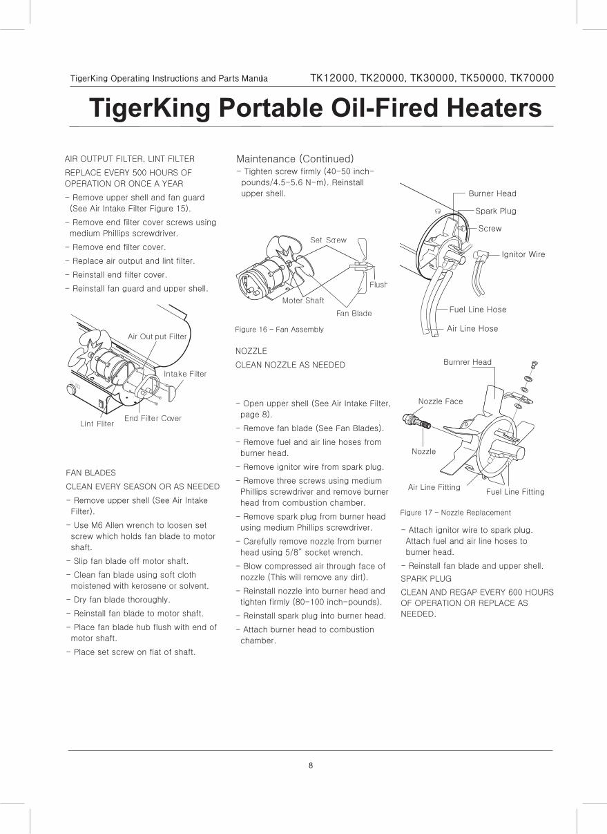
TigerKing Portable Oil-Fired HeatersAIR OUTPUT FILTER, LINT FILTER
REPLACE EVERY 500 HOURS OF
OPERATION OR ONCE A YEAR
- Remove upper shell and fan guard
(See Air Intake Filter Figure 15).
- Remove end filter cover screws using
medium Phillips screwdriver.
- Remove end filter cover.
- Replace air output and lint filter.
- Reinstall end filter cover.
- Reinstall fan guard and upper shell.
FAN BLADES
CLEAN EVERY SEASON OR AS NEEDED
- Remove upper shell (See Air Intake
Filter).
- Use M6 Allen wrench to loosen set
screw which holds fan blade to motor
shaft.
- Slip fan blade off motor shaft.
- Clean fan blade using soft cloth
moistened with kerosene or solvent.
- Dry fan blade thoroughly.
- Reinstall fan blade to motor shaft.
- Place fan blade hub flush with end of
motor shaft.
- Place set screw on flat of shaft.
Air Out put Filter
Intake Filter
End Filter CoverLint Fliter
Maintenance (Continued)- Tighten screw firmly (40-50 inch-
pounds/4.5-5.6 N-m). Reinstall
upper shell.
NOZZLE
CLEAN NOZZLE AS NEEDED
- Open upper shell (See Air Intake Filter,
page 8).
- Remove fan blade (See Fan Blades).
- Remove fuel and air line hoses from
burner head.
- Remove ignitor wire from spark plug.
- Remove three screws using medium
Phillips screwdriver and remove burner
head from combustion chamber.
- Remove spark plug from burner head
using medium Phillips screwdriver.
- Carefully remove nozzle from burner
head using 5/8” socket wrench.
- Blow compressed air through face of
nozzle (This will remove any dirt).
- Reinstall nozzle into burner head and
tighten firmly (80-100 inch-pounds).
- Reinstall spark plug into burner head.
- Attach burner head to combustion
chamber.
- Attach ignitor wire to spark plug.
Attach fuel and air line hoses to
burner head.
- Reinstall fan blade and upper shell.
SPARK PLUG
CLEAN AND REGAP EVERY 600 HOURS
OF OPERATION OR REPLACE AS
NEEDED.
Figure 16 – Fan Assembly
Moter Shaft
Set Screw
Fan Blade
Flush
Ignitor Wire
Screw
Burner Head
Spark Plug
Fuel Line Hose
Air Line Hose
Fuel Line FittingAir Line Fitting
Nozzle
Nozzle Face
Burnrer Head
Figure 17 – Nozzle Replacement
9
TigerKing Operating Instructions and Parts Manual TK12000, TK20000, TK30000, TK50000, TK70000
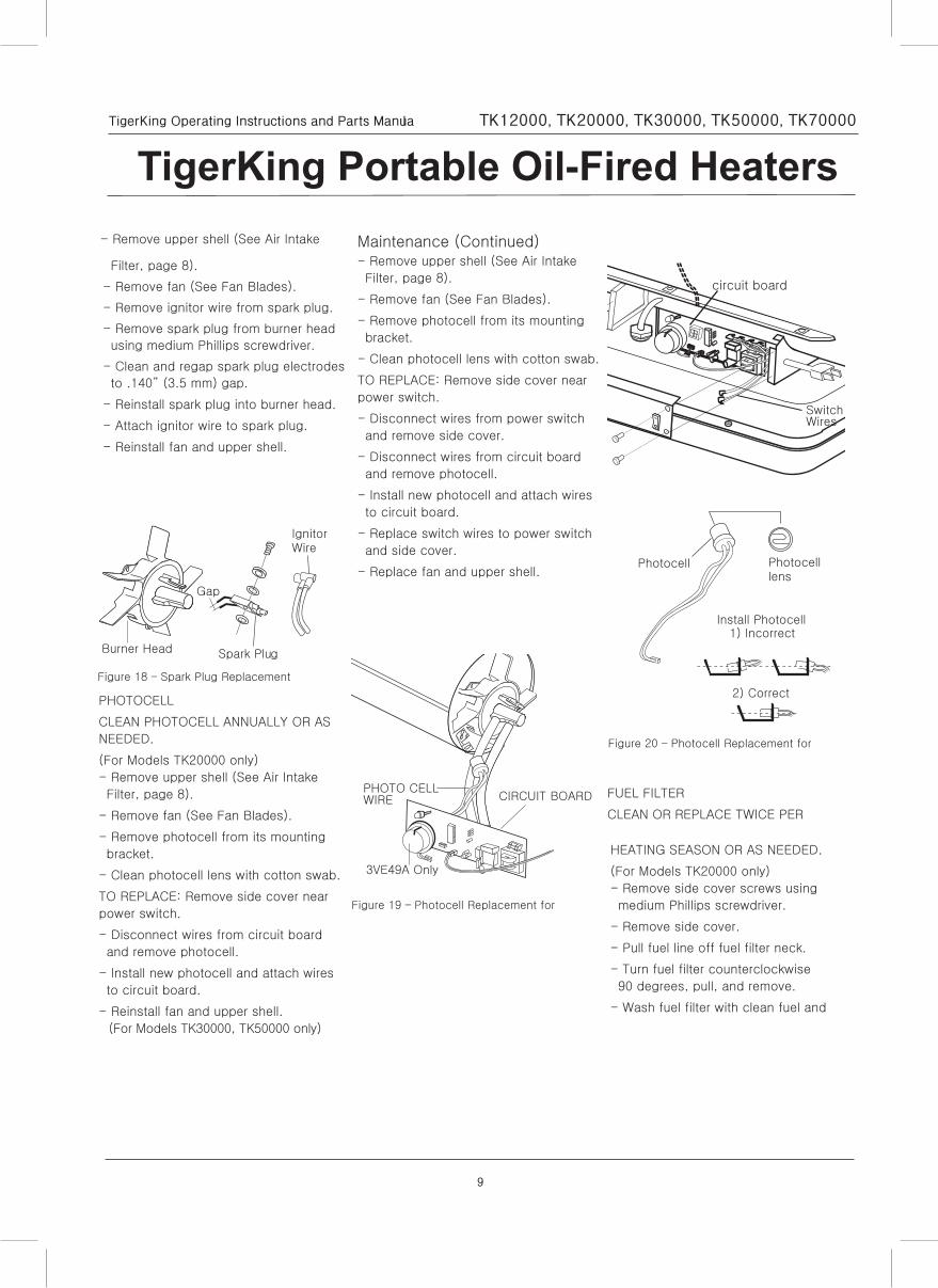
TigerKing Portable Oil-Fired Heaters- Remove upper shell (See Air Intake
Filter, page 8).
- Remove fan (See Fan Blades).
- Remove ignitor wire from spark plug.
- Remove spark plug from burner head
using medium Phillips screwdriver.
- Clean and regap spark plug electrodes
to .140” (3.5 mm) gap.
- Reinstall spark plug into burner head.
- Attach ignitor wire to spark plug.
- Reinstall fan and upper shell.
PHOTOCELL
CLEAN PHOTOCELL ANNUALLY OR AS
NEEDED.
(For Models TK20000 only)
- Remove upper shell (See Air Intake
Filter, page 8).
- Remove fan (See Fan Blades).
- Remove photocell from its mounting
bracket.
- Clean photocell lens with cotton swab.
TO REPLACE: Remove side cover near
power switch.
- Disconnect wires from circuit board
and remove photocell.
- Install new photocell and attach wires
to circuit board.
- Reinstall fan and upper shell.
(For Models TK30000, TK50000 only)
Ignitor Wire
Burner Head
Gap
Spark Plug
Figure 18 – Spark Plug Replacement
Maintenance (Continued)- Remove upper shell (See Air Intake
Filter, page 8).
- Remove fan (See Fan Blades).
- Remove photocell from its mounting
bracket.
- Clean photocell lens with cotton swab.
TO REPLACE: Remove side cover near
power switch.
- Disconnect wires from power switch
and remove side cover.
- Disconnect wires from circuit board
and remove photocell.
- Install new photocell and attach wires
to circuit board.
- Replace switch wires to power switch
and side cover.
- Replace fan and upper shell.
FUEL FILTER
CLEAN OR REPLACE TWICE PER
HEATING SEASON OR AS NEEDED.
(For Models TK20000 only)
- Remove side cover screws using
medium Phillips screwdriver.
- Remove side cover.
- Pull fuel line off fuel filter neck.
- Turn fuel filter counterclockwise
90 degrees, pull, and remove.
- Wash fuel filter with clean fuel and
PHOTO CELL
3VE49A Only
WIRE CIRCUIT BOARD
Figure 19 – Photocell Replacement for
Photocell Photocell lens
Install Photocell1) Incorrect
Figure 20 – Photocell Replacement for
2) Correct
SwitchWires
circuit board
10
TigerKing Operating Instructions and Parts Manual TK12000, TK20000, TK30000, TK50000, TK70000
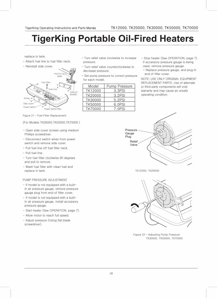
TigerKing Portable Oil-Fired Heatersreplace in tank.
- Attach fuel line to fuel filter neck.
- Reinstall side cover.
(For Models TK30000,TK50000,TK70000 )
- Open side cover screws using medium
Phillips screwdriver.
- Disconnect switch wires from power
switch and remove side cover.
- Pull fuel line off fuel filter neck.
- Pull fuel line.
- Turn fuel filter clockwise 90 degrees
and pull to remove.
- Wash fuel filter with clean fuel and
replace in tank.
PUMP PRESSURE ADJUSTMENT
- If model is not equipped with a built-
in air pressure gauge, remove pressure
gauge plug from end of filter cover.
- If model is not equipped with a built-
in air pressure gauge, install accessory
pressure gauge.
- Start heater (See OPERATION, page 7).
- Allow motor to reach full speed.
- Adjust pressure (Using flat blade
screwdriver).
PHOTO CELL
WIRE
CIRCUIT BOARD
Side cover
Power SwitchPower Switch Wire
Screw
Fuel Filter
Fuel Line
Figure 21 – Fuel Filter Replacement
- Turn relief valve clockwise to increase
pressure.
- Turn relief valve counterclockwise to
decrease pressure.
- Set pump pressure to correct pressure
for each model.
- Stop heater (See OPERATION, page 7).
If accessory pressure gauge is being
used, remove pressure gauge.
- Replace pressure gauge, and plug in
end of filter cover.
NOTE: USE ONLY ORIGINAL EQUIPMENT
REPLACEMENT PARTS. Use of alternate
or third party components will void
warranty and may cause an unsafe
operating condition.
Model Pump Pressure
TK20000 3.2PSI
TK12000 3.3PSI
TK30000 5.2PSITK50000 6.0PSITK70000 7.0PSI
PressureGaugePlug
ReliefValve
Figure 22 – Adjusting Pump Pressure
TK30000, TK50000, TK70000
TK12000, TK20000
11
TigerKing Operating Instructions and Parts Manual TK12000, TK20000, TK30000, TK50000, TK70000
TigerKing Portable Oil-Fired Heaters
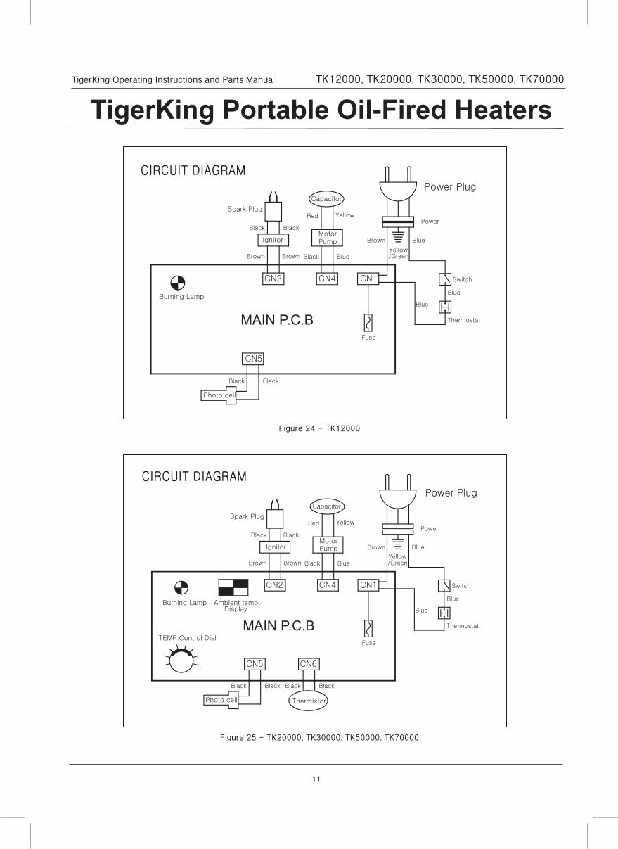
Power Plug
Figure 24 - TK12000
Figure 25 - TK20000, TK30000, TK50000, TK70000
12
TigerKing Operating Instructions and Parts Manual TK12000, TK20000, TK30000, TK50000, TK70000
TigerKing Portable Oil-Fired Heaters
Repair Parts List for Portable Oil-Fired Heaters
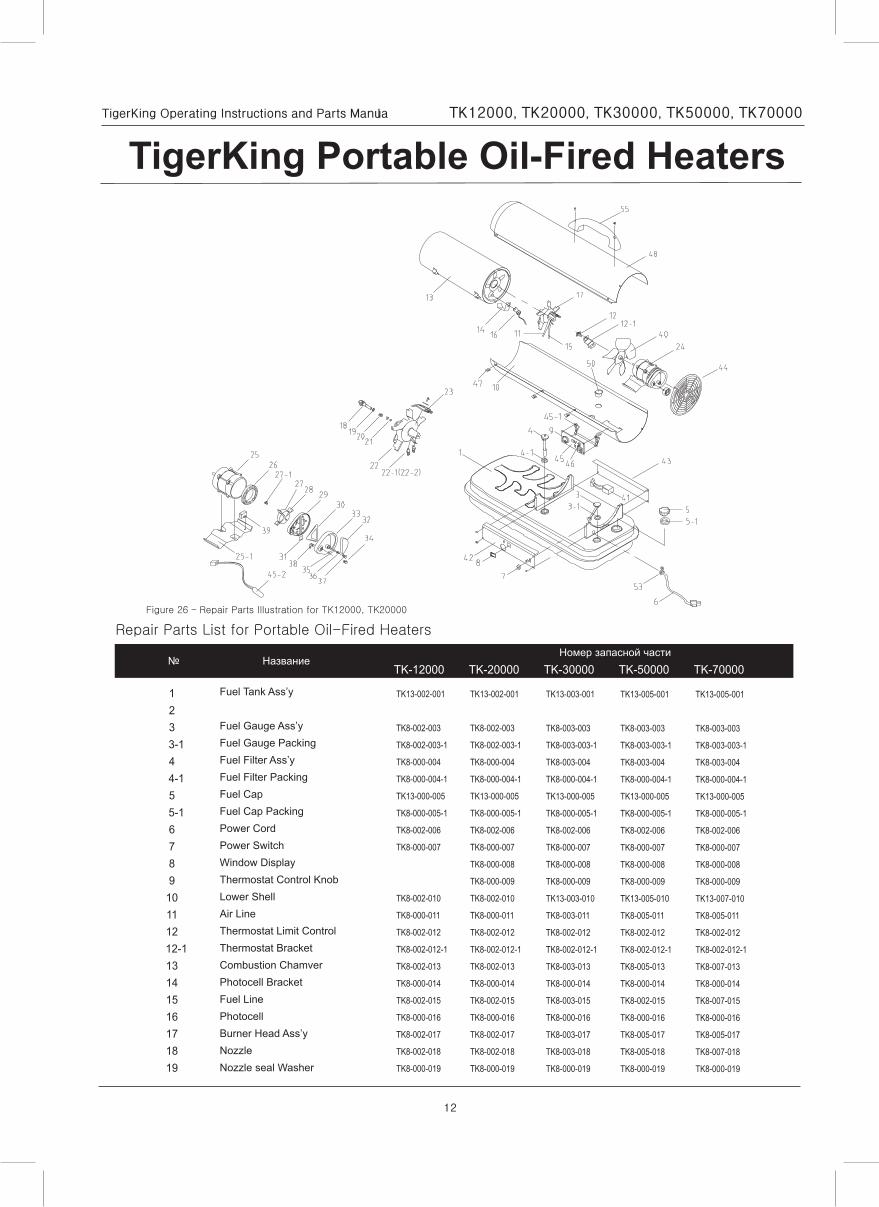
Figure 26 – Repair Parts Illustration for TK12000, TK20000
TK-12000 TK-20000 TK-30000 TK-50000 TK-70000
123
3-14
4-15
5-16789101112
12-113141516171819
TK13-002-001
TK8-002-003
TK8-002-003-1
TK8-000-004
TK8-000-004-1
TK13-000-005
TK8-000-005-1
TK8-002-006
TK8-000-007
TK8-002-010
TK8-000-011
TK8-002-012
TK8-002-012-1
TK8-002-013
TK8-000-014
TK8-002-015
TK8-000-016
TK8-002-017
TK8-002-018
TK8-000-019
TK13-002-001
TK8-002-003
TK8-002-003-1
TK8-000-004
TK8-000-004-1
TK13-000-005
TK8-000-005-1
TK8-002-006
TK8-000-007
TK8-000-008
TK8-000-009
TK8-002-010
TK8-000-011
TK8-002-012
TK8-002-012-1
TK8-002-013
TK8-000-014
TK8-002-015
TK8-000-016
TK8-002-017
TK8-002-018
TK8-000-019
TK13-003-001
TK8-003-003
TK8-003-003-1
TK8-003-004
TK8-000-004-1
TK13-000-005
TK8-000-005-1
TK8-002-006
TK8-000-007
TK8-000-008
TK8-000-009
TK13-003-010
TK8-003-011
TK8-002-012
TK8-002-012-1
TK8-003-013
TK8-000-014
TK8-003-015
TK8-000-016
TK8-003-017
TK8-003-018
TK8-000-019
TK13-005-001
TK8-003-003
TK8-003-003-1
TK8-003-004
TK8-000-004-1
TK13-000-005
TK8-000-005-1
TK8-002-006
TK8-000-007
TK8-000-008
TK8-000-009
TK13-005-010
TK8-005-011
TK8-002-012
TK8-002-012-1
TK8-005-013
TK8-000-014
TK8-002-015
TK8-000-016
TK8-005-017
TK8-005-018
TK8-000-019
TK13-005-001
TK8-003-003
TK8-003-003-1
TK8-003-004
TK8-000-004-1
TK13-000-005
TK8-000-005-1
TK8-002-006
TK8-000-007
TK8-000-008
TK8-000-009
TK13-007-010
TK8-005-011
TK8-002-012
TK8-002-012-1
TK8-007-013
TK8-000-014
TK8-007-015
TK8-000-016
TK8-005-017
TK8-007-018
TK8-000-019
Fuel Tank Ass’y
Fuel Gauge Ass’yFuel Gauge PackingFuel Filter Ass’yFuel Filter PackingFuel CapFuel Cap PackingPower CordPower SwitchWindow DisplayThermostat Control KnobLower ShellAir LineThermostat Limit ControlThermostat BracketCombustion ChamverPhotocell BracketFuel LinePhotocellBurner Head Ass’yNozzleNozzle seal Washer
13
TigerKing Operating Instructions and Parts Manual TK12000, TK20000, TK30000, TK50000, TK70000
TigerKing Portable Oil-Fired Heaters
Repair Parts List for Portable Oil-Fired Heaters
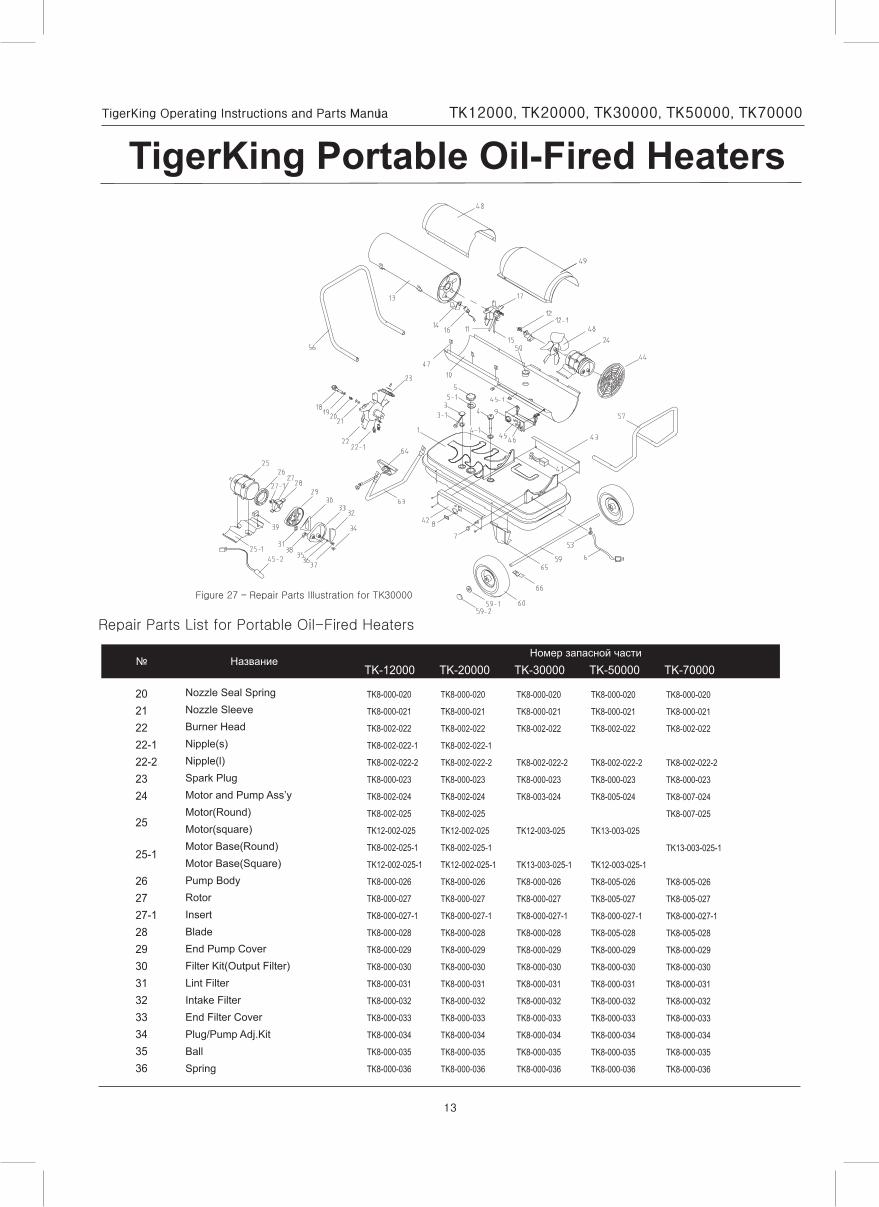
Figure 27 – Repair Parts Illustration for TK30000
TK-12000 TK-20000 TK-30000 TK-50000 TK-70000
20212222-122-22324
25
25-1
262727-1282930313233343536
TK8-000-020
TK8-000-021
TK8-002-022
TK8-002-022-1
TK8-002-022-2
TK8-000-023
TK8-002-024
TK8-002-025
TK12-002-025
TK8-002-025-1
TK12-002-025-1
TK8-000-026
TK8-000-027
TK8-000-027-1
TK8-000-028
TK8-000-029
TK8-000-030
TK8-000-031
TK8-000-032
TK8-000-033
TK8-000-034
TK8-000-035
TK8-000-036
TK8-000-020
TK8-000-021
TK8-002-022
TK8-002-022-1
TK8-002-022-2
TK8-000-023
TK8-002-024
TK8-002-025
TK12-002-025
TK8-002-025-1
TK12-002-025-1
TK8-000-026
TK8-000-027
TK8-000-027-1
TK8-000-028
TK8-000-029
TK8-000-030
TK8-000-031
TK8-000-032
TK8-000-033
TK8-000-034
TK8-000-035
TK8-000-036
TK8-000-020
TK8-000-021
TK8-002-022
TK8-002-022-2
TK8-000-023
TK8-003-024
TK12-003-025
TK13-003-025-1
TK8-000-026
TK8-000-027
TK8-000-027-1
TK8-000-028
TK8-000-029
TK8-000-030
TK8-000-031
TK8-000-032
TK8-000-033
TK8-000-034
TK8-000-035
TK8-000-036
TK8-000-020
TK8-000-021
TK8-002-022
TK8-002-022-2
TK8-000-023
TK8-005-024
TK13-003-025
TK12-003-025-1
TK8-005-026
TK8-005-027
TK8-000-027-1
TK8-005-028
TK8-000-029
TK8-000-030
TK8-000-031
TK8-000-032
TK8-000-033
TK8-000-034
TK8-000-035
TK8-000-036
TK8-000-020
TK8-000-021
TK8-002-022
TK8-002-022-2
TK8-000-023
TK8-007-024
TK8-007-025
TK13-003-025-1
TK8-005-026
TK8-005-027
TK8-000-027-1
TK8-005-028
TK8-000-029
TK8-000-030
TK8-000-031
TK8-000-032
TK8-000-033
TK8-000-034
TK8-000-035
TK8-000-036
Nozzle Seal SpringNozzle SleeveBurner HeadNipple(s)Nipple(l)Spark PlugMotor and Pump Ass’yMotor(Round)Motor(square)Motor Base(Round)Motor Base(Square)Pump BodyRotorInsertBladeEnd Pump CoverFilter Kit(Output Filter)Lint FilterIntake FilterEnd Filter CoverPlug/Pump Adj.KitBallSpring
14
TigerKing Operating Instructions and Parts Manual TK12000, TK20000, TK30000, TK50000, TK70000
TigerKing Portable Oil-Fired Heaters
Repair Parts List for Portable Oil-Fired Heaters
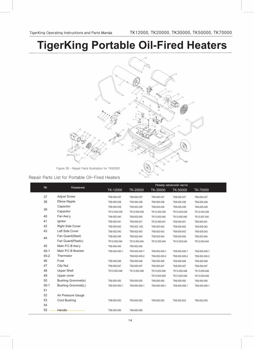
Figure 28 – Repair Parts Illustration for TK50000
TK-12000 TK-20000 TK-30000 TK-50000 TK-70000
3738
39
40414243
44
4545-145-2464748495050-15152535455
TK8-000-037
TK8-000-038
TK8-000-039
TK12-003-039
TK8-002-040
TK8-000-041
TK8-000-042
TK8-002-043
TK8-002-044
TK12-002-044
TK8-000-045
TK8-002-045-1
TK8-000-046
TK8-000-047
TK13-002-048
TK8-000-050
TK8-000-050-1
TK8-002-053
TK8-000-055
TK8-000-037
TK8-000-038
TK8-002-039
TK12-003-039
TK8-002-040
TK8-000-041
TK8-002 -042
TK8-002-043
TK8-002-044
TK12-002-044
TK8-002-045
TK8-002-045-1
TK8-002-045-2
TK8-000-046
TK8-000-047
TK13-002-048
TK8-000-050
TK8-000-050-1
TK8-002-053
TK8-000-055
TK8-000-037
TK8-000-038
TK8-003-039
TK12-003-039
TK13-003-040
TK12-000-041
TK8-003-042
TK8-003-043
TK8-003-044
TK12-003-044
TK8-002-045-1
TK8-002-045-2
TK8-000-046
TK8-000-047
TK13-003-048
TK13-003-049
TK8-000-050
TK8-000-050-1
TK8-002-053
TK8-000-037
TK8-000-038
TK8-005-039
TK12-003-039
TK13-005-040
TK8-000-041
TK8-005-042
TK8-005-043
TK8-003-044
TK12-003-044
TK8-002-045-1
TK8-002-045-2
TK8-000-046
TK8-000-047
TK13-005-048
TK13-003-049
TK8-000-050
TK8-000-050-1
TK8-002-053
TK8-000-037
TK8-000-038
TK8-005-039
TK12-003-039
TK13-007-040
TK8-000-041
TK8-005-042
TK8-005-043
TK8-003-044
TK12-003-044
TK8-002-045-1
TK8-002-045-2
TK8-000-046
TK8-000-047
TK13-005-048
TK13-003-049
TK8-000-050
TK8-000-050-1
TK8-002-053
Adjust ScrewElbow NippleCapacitorCapacitorFan Ass’yIgnitorRight Side CoverLeft Side CoverFan Guard(Steel)Fan Guard(Plastic)Main P.C.B Ass’yMain P.C.B BracketThermistorFuseClip NutUpper ShellUpper coverBushing Grommet(s)Bushing Grommet(L)
Air Pressure GaugeCord Bushing
Handle
15
TigerKing Operating Instructions and Parts Manual TK12000, TK20000, TK30000, TK50000, TK70000
TigerKing Portable Oil-Fired Heaters
Repair Parts List for Portable Oil-Fired Heaters
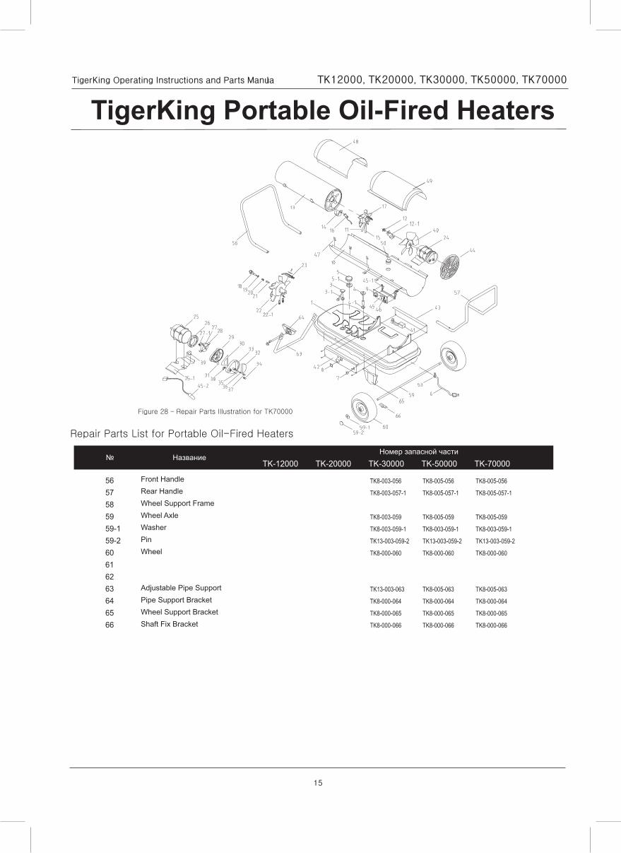
Figure 28 – Repair Parts Illustration for TK70000
Front HandleRear HandleWheel Support FrameWheel AxleWasherPinWheel
Adjustable Pipe SupportPipe Support BracketWheel Support BracketShaft Fix Bracket
TK-12000 TK-20000 TK-30000 TK-50000 TK-70000
5657585959-159-260616263646566
TK8-003-056
TK8-003-057-1
TK8-003-059
TK8-003-059-1
TK13-003-059-2
TK8-000-060
TK13-003-063
TK8-000-064
TK8-000-065
TK8-000-066
TK8-005-056
TK8-005-057-1
TK8-005-059
TK8-003-059-1
TK13-003-059-2
TK8-000-060
TK8-005-063
TK8-000-064
TK8-000-065
TK8-000-066
TK8-005-056
TK8-005-057-1
TK8-005-059
TK8-003-059-1
TK13-003-059-2
TK8-000-060
TK8-005-063
TK8-000-064
TK8-000-065
TK8-000-066
16
TigerKing Operating Instructions and Parts Manual TK12000, TK20000, TK30000, TK50000, TK70000
TigerKing Portable Oil-Fired Heaters
noitcA evitcerroC)s(esuaC elbissoPmotpmyS
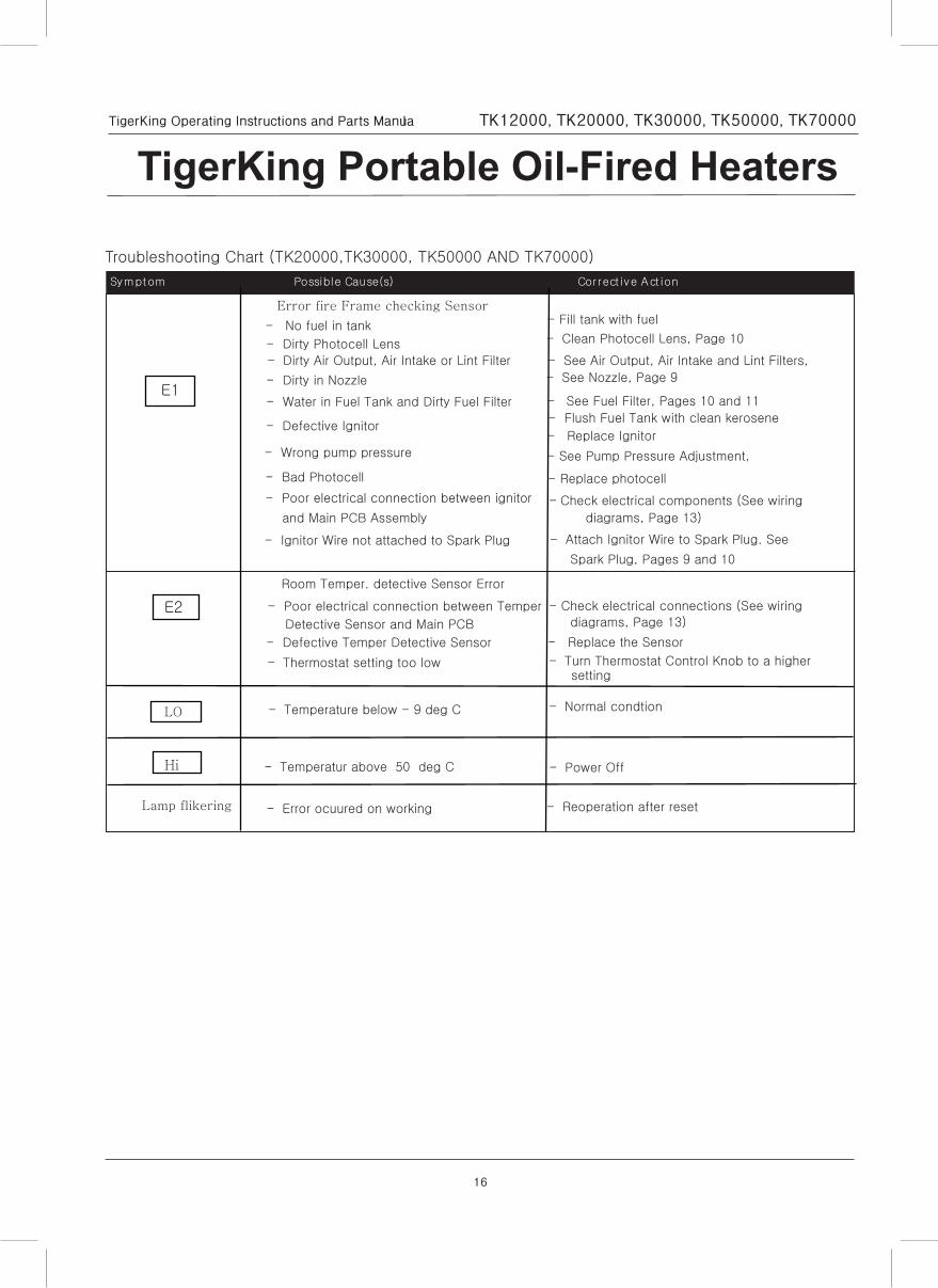
- Defective Temper Detective Sensor
- Dirty Air Output, Air Intake or Lint Filter
- Dirty Photocell Lens
- Bad Photocell
- No fuel in tank
- Wrong pump pressure
- Dirty in Nozzle
- Water in Fuel Tank and Dirty Fuel Filter
- Poor electrical connection between ignitor
and Main PCB Assembly
- Ignitor Wire not attached to Spark Plug
- Defective Ignitor
- Thermostat setting too low
- See Pump Pressure Adjustment,
- See Air Output, Air Intake and Lint Filters,
- See Fuel Filter, Pages 10 and 11
- See Nozzle, Page 9
- Clean Photocell Lens, Page 10
- Check electrical components (See wiring
diagrams, Page 13)
- Fill tank with fuel
- Flush Fuel Tank with clean kerosene
- Attach Ignitor Wire to Spark Plug. See
Spark Plug, Pages 9 and 10
- Replace Ignitor
- Turn Thermostat Control Knob to a highersetting
- Check electrical connections (See wiring
diagrams, Page 13)
Troubleshooting Chart (TK20000,TK30000, TK50000 AND TK70000)
E1
E2
Error fire Frame checking Sensor
Room Temper. detective Sensor Error
- Poor electrical connection between Temper
Detective Sensor and Main PCB
- Replace the Sensor
- Replace photocell
LO
- Temperatur above 50 deg C
- Normal condtion
Hi
Lamp flikering
- Temperature below - 9 deg C
- Power Off
- Error ocuured on working - Reoperation after reset
Related Documents