Tie Beam Reported by Sarah Jane S. Pahimnayan

Welcome message from author
This document is posted to help you gain knowledge. Please leave a comment to let me know what you think about it! Share it to your friends and learn new things together.
Transcript

Tie BeamReported bySarah Jane S. Pahimnayan

Tie Beam
Definition: A horizontal beam forming the base of a
triangular truss for a pitched roof, connecting the two side walls and supporting a pair of principals.
(Miscellaneous Technologies / Building) a horizontal beam that serves to prevent two other structural members from separating, esp. one that connects two corresponding rafters in a roof or roof truss.

Tie Beam
B- TIE BEAM

Tie Beam

Tie Beam Tie-beams are constructed atop the walls at each floor level.
Beam reinforcement can be assembled in the form of a cage. The reinforcement is similar to column reinforcement: four longitudinal bars and stirrups at equal spacing. To ensure the effectiveness of tie-beams in resisting earthquake loads, longitudinal bars should have a 90° hooked anchorage at the intersections. The hook length should be at least 500 mm.
Most codes agree that four 10 mm diameter deformed bars (4-10 mm bars) are adequate for longitudinal reinforcement. Longitudinal bars should be lapped by a minimum 500 mm length. At least 6 mm diameter stirrups at 200 mm spacing (6 mm @200) should be provided.

Tie Beam Between Footings
A tie beam sustaining seismic actions will be sized according to the forces carried.
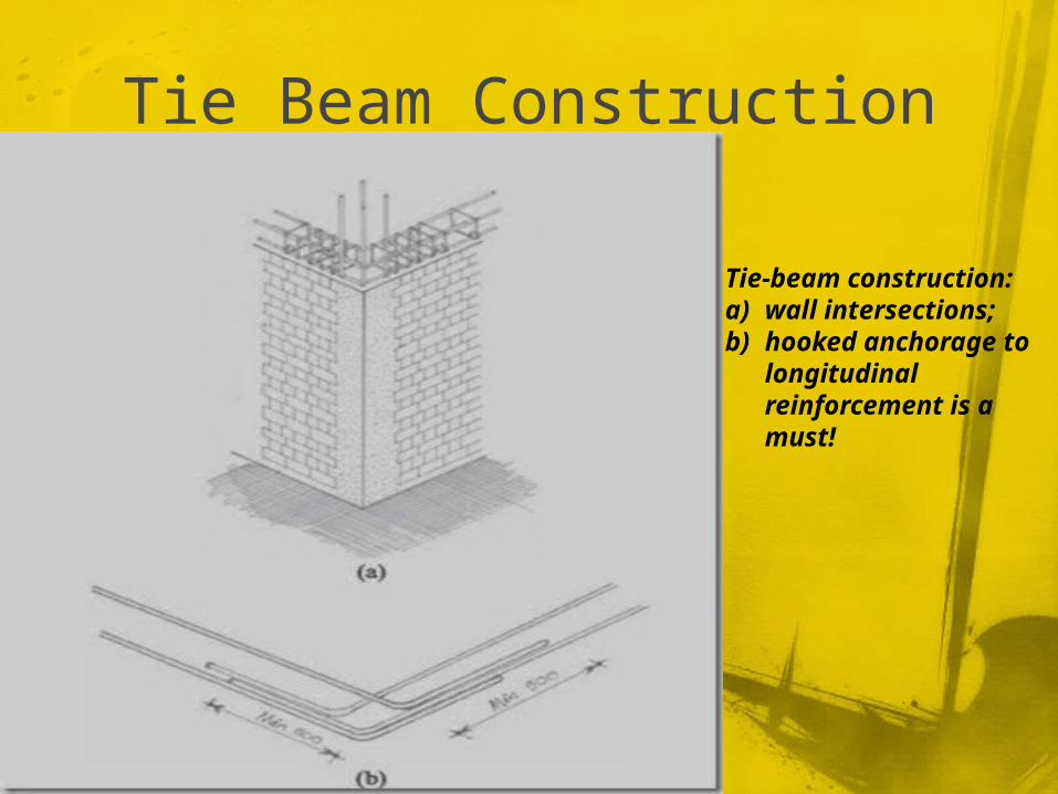
Tie Beam Construction
Tie-beam construction: a) wall intersections; b) hooked anchorage to
longitudinal reinforcement is a must!

Tie Beam Reinforcement
Tie-beam reinforcementProper detailing of the tie beam to tie column connections is a must for satisfactory earthquake performance of the entire building. Reinforcing bars must be properly anchored. Note that the tie-column reinforcement needs to be extended into the tie-beam as much as possible, preferably up to the underside of the top tie-beam reinforcement. A hooked anchorage needs to be provided (90° hooks) both for the tie-column and tie-beam reinforcement.

Detailing requirement for the tie beam to tie column connection
The tie-beam cross sectional dimensions should not be less than 100 mm by 100 mm. The beam width should be equal to the wall thickness. When the tie-beam is a part of the floor slab, the tie-beam reinforcement may be considered a part of the slab reinforcement. In that case, the slab thickness should be the same as the tie-beam depth.

Lintel beam reinforcement
Lintel beam reinforcement Special lintel beams may be required across larger openings having a width exceeding 1.5 m. Additional reinforcement bars need to be provided. Lintel beams can be integrated with the tie-beams at the floor level.
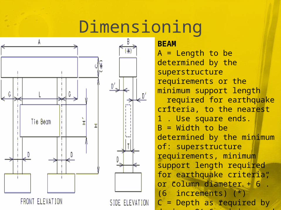
DimensioningBEAMA = Length to be determined by the superstructure requirements or the minimum support length required for earthquake criteria, to the nearest 1”. Use square ends.B = Width to be determined by the minimum of: superstructure requirements, minimum support length required for earthquake criteria, or column diameter + 6”. (6” increments) (*)C = Depth as required by design. 2’-6” minimum and no less than the column diameter. (3” increments) (*) Ratio of beam width to beam depth, B/C, shall be ≤ 1.25

DimensioningCOLUMNSD = Column diameter. 3’-0” minimum. (6” increments)D' = Beam width overhang. Controlled by one of the following:1) Beam width controlled by superstructure requirements 3” ≤ D' ≤ 6”2) Beam width controlled by minimum support length required for earthquake criteria.3” ≤ D' ≤ 15”L = Spacing as determined by design, with 30'-0" maximum. (1” increments)G = Overhang as determined by design, with no limits.H = Column height as required by grade and footing elevations.

Dimensioning
Tie BeamT = Tie beam thickness. Minimum T = 0.5 x (column diameter).H' = See bottom elevations of tie beam given on the Design Layout. Minimum H' = 2 x T (round to the next foot higher).

Foundation Shifting or WashoutGenerally “shifting” or “washout” only occurs in areas with terrain that is uneven or close to streams and rivers. If you have a very steep terrain that you need to install footings, there is a general rule of thumb to use.You should dig the footing as deep into the ground as you can. This prevents shifting of the footing because of the ground wanting to slide down. The deeper you dig the less chance of washout. Another way to prevent shifting is to “tie beam” your footings together. This is a concrete filled trench with rebar from footing to footing. This will also have to be dug below your frost line. The tie beam anchors the footings together to hook into the ground.
References
http://www.thefreedictionary.com/tie+beamhttp://constructiondetails.us.cype.com/CSZ01
1.htmlhttp://epg.modot.org/index.php?title=751.31
_Open_Concrete_Intermediate_Bents#751.31.1.4_Tie_Beam
http://toptutor.blogsome.com/2006/11/10/foundation-shifting-or-washout/

Thank You For Listening ! ^_^
Related Documents


