TIA/EIA TELECOMMUNICATIONS SYSTEMS BULLETIN Transmission Performance Specifications for Field Testing of Unshielded Twisted-Pair Cabling Systems TSB67 OCTOBER 1995 TELECOMMUNICATIONS INDUSTRY ASSOCIATION

Welcome message from author
This document is posted to help you gain knowledge. Please leave a comment to let me know what you think about it! Share it to your friends and learn new things together.
Transcript
TIA/EIATELECOMMUNICATIONS SYSTEMS BULLETIN
Transmission Performance Specifications for Field Testing of Unshielded Twisted-Pair Cabling Systems
TSB67
OCTOBER 1995
TELECOMMUNICATIONS INDUSTRY ASSOCIATION
NOTICE
TIA/EIA Engineering Standards and Publications are designed to serve the public interest through eliminating misunderstandings between manufacturers and purchasers, facilitating interchangeability and improvement of products, and assisting the purchaser in selecting and obtaining with minimum delay the proper product for his particular need. Existence of such Standards and Publications shall not in any respect preclude any member or nonmember of TIA/EIA from manufacturing or selling products not conforming to such Standards and Publications, nor shall the existence of such Standards and Publications preclude their voluntary use by those other than TIA/EIA members, whether the standard is used either domestically or internationally.
Standards, Publications and Bulletins are adopted by TIA/EIA in accordance with the American National Standards Institute (ANSI) patent policy. By such action, TIA/EIA does not assume any liability to any patent owner, nor does it assume any obligation whatever to parties adopting the Standard, Publication or Bulletin.
Technical Bulletins are distinguished from TIA/EIA Standards and Interim Standards, in that they contain a compilation of engineering data or information useful to the technical community, and represent approaches to good engineering practices that are suggested by the formulating committee.
This Bulletin is not intended to preclude or discourage other approaches that similarly represent good engineering practice, or that may be acceptable to, or have been accepted by, appropriate bodies. Parties who wish to bring other approaches to the attention of the formulating committee to be considered for inclusion in future revisions of this Bulletin are encouraged to do so. It is the intention of the formulating committee to revise and update this Bulletin from time to time as may be occasioned by changes in technology, industry practice, or government regulations, or for other appropriate reasons.
(From Project No. 3287, formulated under the cognizance of the TIA TR-41.8 Subcommittee on Commercial and Residential Building a Building Cabling Systems.)
Published by
TELECOMMUNICATIONS INDUSTRY ASSOCIATION 1995
Standards and Technology Department 2500 Wilson Boulevard
Arlington, VA 22201
PRICE: Please refer to the current Catalog of EIA, JEDEC and TIA STANDARDS and ENGINEERING PUBLICATIONS
or call Global Engineering Documents, USA and Canada (1-800-854-7179)International (303)397-7956)
All rights reservedPrinted in the U.S.A.
PLEASE!
DON'T VIOLATE THE LAW!
This document is copyrighted by the TIA and may not be reproduced without permission.
Organizations may obtain permission to reproduce a limited number of copies through enteringinto a license agreement. For information, contact:
Global Engineering Documents15 Inverness Way East
Englewood, CO 80112-5704 or callU.S.A. and Canada 1-800-854-7179, International (303)397-7956
ANSI/TIA/EIA-569-AForeword
(This foreword is not part of this Standard)
This Standard was produced by TIA/EIA Working Group TR-41.8.3 and was a joint effort between the U.S. and Canada, with the Canadian Standards Association publishing the Canadian equivalent of this Standard (CSA T530) at approximately the same time.
Approval of Standard
This Standard was approved by TIA/EIA Working Group TR-41.8.3, TIA/EIA Sub committee TR-41.8, TIA/EIA Technical Committee TR-41, and the American National Standards Institute (ANSI).
Contributing organizations
More than 30 organizations within the telecommunications industry contributed their expertise to the development of this Standard (including manufacturers, consultants, end users, and other organizations).
The initial development of the standard was carried out with the support of the American Institute of Architects and the Construction Specifications Institute. Because this standard greatly influences both the design and construction of commercial buildings, it was important that these two organizations were cognizant of this particular standards activity. Additionally, the prospect of the architectural and construction industries being confronted with a national standard related to access to telecommunications services made it necessary that they be given a clear rationale for the need of such a standard.
Documents superseded
This Standard replaces the first edition of ANSI/EIA/TIA-569, originally published October, 1990.
Significant technical changes from previous edition
Terminology changes:
-- Work station has been replaced by work area. This change harmonizes use of terminology across all telecommunications infrastructure standards (ANSI/TIA/EIA-568-A, -569-A, -606 and -607).
-- Conduit dimensions have been replaced by their respective electrical trade-size nomenclature. For example, 21 (¾) trade size conduit refers to a conduit with a metric trade designator of 21 and an English trade designator of ¾. Units (mm, in) are not included with the designator it is understood that the metric designator is in millimeters and the English designator is in inches. A table is located in annex B showing trade-size designators and their corresponding dimensions.
-- Manhole has been replaced by maintenance hole to degenderize the term.
-- Maintenance holes, handholes, pull boxes, and splice boxes are now considered spaces for the purposes of this Standard to harmonize with the administration standard (ANSI/TIA/EIA-606).
Technical global changes:
-- Grounding and bonding requirements have been harmonized with ANSI/TIA/EIA-607 throughout
this Standard.
-- Administrative requirements have been referenced to ANSI/TIA/EIA-606.
Highlights of changes made to the various sections:
-- Foreword: This foreword section has been changed per the requirements of the TIA style manual.
-- Section 3: All definitions have been harmonized across all telecommunications infrastructure standards.
-- Section 4: Transition box sizing has changed. Backbone-related information has been moved to sections 5 and normative annex C. Consolidation points and multi-user telecommunications outlet assemblies have been added.
-- Section 5: Only intrabuilding backbone pathways and spaces are now considered.
-- Section 6: Pathway and space requirements for open office cabling are now included.
-- Section 7: The telecommunications closet diagram is changed.
-- Section 8: Floor loading and vibration requirements for equipment rooms have changed. Additionally, requirements for a main terminal space have been added.
-- Section 9: All interbuilding requirements have been moved to normative annex C.
-- Section 10: Pathway separation from EMI sources has significant changes.
-- The firestopping annex has been significantly modified and changed from an informative to a normative annex.
-- The Symbols annex was removed because ANSI/TIA/EIA-606 includes symbols.
-- A new normative annex C was created, placing all material related to interbuilding pathway/space topics under one heading. It is the intent of TR-41.8.3 to remove this annex at a later date, after TIA issues a new standard covering the same material (tentatively, a standard on outside plant).
NOTE - Pathway fill is under study by TR-41.8.3.
Relationship to other standards and documents
This Standard is a member of a family of standards related to the telecommunications infrastructure supporting modern commercial buildings. Other standards within this family are
-- Commercial Building Telecommunications Cabling Standard (ANSI/TIA/EIA-568-A);
-- Residential and Light Commercial Telecommunications Wiring Standard (ANSI/EIA/TIA-570);
-- Administration Standard for the Telecommunications Infrastructure of Commercial Buildings (ANSI/TIA/EIA-606);
-- Commercial Building Grounding and Bonding Requirements for Telecommunications (ANSI/TIA/EIA-607).
A useful supplement to this Standard is the Building Industry Consulting Service International (BICSI) Telecommunications Distribution Methods Manual. This manual provides practices and methods by which many of the requirements of this Standard are implemented.
The National Electrical Code (ANSI/NFPA-70) contains requirements for telecommunications pathways within buildings that govern the use of this Standard.
Other references are listed in annex D.
The following list may be useful to the reader in acquiring safety and other additional code-related information:
a) American Insurance Association:National Building Code (NBC)
b) Building Officials and Code Administrators (BOCA):The BOCA Basic Building Code
c) Institute of Electrical & Electronics Engineers (IEEE):National Electrical Safety Code
d) International Conference of Building Officials (ICBO):Uniform Building Code (UBC)
e) National Fire Protection Association (NFPA):
1) Automatic Fire Detectors
2) Auxiliary Protective Signaling Systems
3) Central Station Signaling Systems
4) Life Safety Code
5) Lightning Protection Code
6) Local Protective Signaling Systems
7) National Electrical Code (NEC)
8) Remote Station Protective Signaling Systems
9) Proprietary Protective Signaling Systems
10) Protection of Electronic Computer/Data Processing Equipment
f) Southern Building Code Congress International, Inc.:Standard Building Code (SBC)
This Standard does not replace any code, either partially or wholly. The reader should also be aware of local codes which may impact the use of this Standard.
Annexes
Annexes A and C of this Standard are normative and considered a mandatory part of this Standard. Annexes B and D are informative and not considered a mandatory part of this Standard.
ANSI/TIA/EIA-569-A Commercial Building Standards for Telecommunications Pathways and Spaces
Contents
Title Page
Foreword
1_Introduction
2_Scope
3_Definitions, abbreviations and acronyms, units
4 _Horizontal pathways and related spaces
5_Intrabuilding backbone pathways and related spaces
6_Work area
7_Telecommunications closet
8 _Equipment room
9_Entrance facilities
10_Miscellaneous items
Annex A (normative) Firestopping
Annex B (informative) Additional section information
Annex C (normative) Interbuilding backbone pathways and related spaces
Annex D (informative) Reference
Figures

Tables
ANSI/TIA/EIA-569-A Commercial Building Standards for Telecommunications Pathways and Spaces
Contents
Title Page
Foreword
1_Introduction
1.1_General
1.2_Purpose
1.3_Expected usefulness
1.4_Relation to other organizations
1.5_Mandatory, advisory terms
1.6_Metric equivalents of U.S. customary units
1.7_Life of this Standard
2_Scope
2.1_General
2.2_Basic building elements
2.3_Normative references
3_Definitions, abbreviations and acronyms, units
3.1_Definitions
3.2_Abbreviations and acronyms
3.3_Units
4 _Horizontal pathways and related spaces
4.1_General
4.2_Underfloor pathways
4.3_Access floor
4.4 Conduit44
4.5_Cable trays and wireways
4.6_Ceiling pathway
4.7_Perimeter pathways
4.8_Miscellaneous
5_Intrabuilding backbone pathways and related spaces
5.1_General
5.2_Design guidelines
6_Work area
6.1_General
6.2_Telecommunications outlet locations
6.3_Furniture pathways and spaces
6.4_Control center, attendant, and reception areas
7_Telecommunications closet
7.1_General
7.2_Design considerations
8 _Equipment room
8.1_General
8.2 _Design considerations
8.3_Main terminal space
9_Entrance facilities
9.1_General
9.2 _Entrance location considerations
9.3_Service entrance pathway
9.4_Entrance point
9.5_Entrance room or space
10_Miscellaneous items
10.1_Firestopping
10.2_Elevator telecommunications
10.3_Horizontal pathway separation from EMI sources
Annex A (normative) Firestopping
A.1_Scope
A.2_Terminology and definitions
A.3_Firestops
A.4_Quality control considerations
A.5_Categories of firestop systems
A.6_Design consideration checklist
Annex B (informative) Additional section information
B.1_General
B.2_Horizontal pathways
B.3_Smaller building telecommunications closet
B.4_Requirements for equipment delivery
B.5_Grounding and bonding
Annex C (normative) Interbuilding backbone pathways and related spaces
C.1_General
C.2 _Building site and entrance considerations
C.3_Interbuilding and entrance pathways
C.4_General considerations for pathway types
C.5_Interbuilding pathway design considerations
C.6_Space design considerations
Annex D (informative) Reference
Figures
Figure 2.2-1_Intrabuilding elements
Figure 4.2-1_Single-level underfloor duct
Figure 4.2-2_Two-level underfloor duct
Figure 4.2-3_Flushduct underfloor system
Figure 4.2-4_Multichannel raceway
Figure 4.2-5_Header duct closet termination
Figure 4.2-6_Underfloor duct layout
Figure 4.2-7_Steel cellular floor
Figure 4.2-8_Concrete cellular floor
Figure 4.2-9_Trenchduct cellular floor
Figure 4.3-1_Typical access floor
Figure 4.5-1_Ventilated cable tray
Figure 4.5-2_Lay-in wireway
Figure 4.6-1_Typical utility column
Figure 4.6-2_Typical ceiling distribution system
Figure 4.7-1_Typical perimeter raceway
Figure 4.8-1_Typical transition boxes in columns
Figure 5.2-1_Typical office building layout
Figure 5.2-2_Typical sleeve and slot installations
Figure 6.3-1_Dimensions for furniture telecommunications outlet opening
Figure 7.2-1_Typical floor layout
Figure 7.2-2_Typical telecommunications closet
Figure 9.3-1_Typical Underground Entrance
Figure 9.4-1_Entrance conduit or sleeve termination
Figure 9.4-2_Encased entrance conduit termination
Figure A.5-1_Mechanical firestops
Figure B.3-1_Typical shallow closet
Figure C.1-1_Typical interbuilding underground layout
Figure C.4-1_Typical Underground Entrance
Figure C.4-2_Plate wall strap
Figure C.4-3_Large cable entrance
Figure C.4-4_Small cable entrance
Figure C.4-5_Attachment unfinished buildings
Figure C.4-6_Typical tunnel section
Figure C.5-1_Entrance conduit or sleeve termination
Figure C.5-2_Maximum section length between maintenance holes
Figure C.6-1_Typical maintenance hole (Type A)
Figure C.6-2_Typical handhole
Tables
Table 4.4-1_Conduit sizing
Table 4.8-1_Transition box sizes
Table 5.2-1_Conduit fill for backbone cable
Table 5.2-2_Pull box sizing
Table 5.2-3_Splice box sizing
Table 7.2-1_Telecommunications closet size
Table 8.2-1_Equipment room floor space
Table 8.2-2_Contamination limits
Table 8.3-1_Minimum termination wall length
Table 8.3-2_Minimum termination floor space
Table B.1-1_Conduit dimensions
Table B.2-1_Performance criteria for dynamic loading
Table B.2-2_Performance criteria for static loading
Table C.5-1_Conduit fill for backbone cable
ANSI/TIA/EIA-569-ACOMMERCIAL BUILDING STANDARD FOR TELECOMMUNICATIONS
PATHWAYS AND SPACES
1 Introduction
1.1 General
1.1.1 This Standard recognizes three fundamental concepts related to telecommunications and buildings:
a) Buildings are dynamic.
Over the life of a building, remodeling is more the rule than the exception. This Standard recognizes, in a positive way, that change takes place.
b) Building telecommunications systems and media are dynamic.
Over the life of a building, both telecommunications equipment and media change dramatically. This Standard recognizes this fact by being as independent as possible from specific vendor equipment and media.
c) Telecommunications is more than just voice and data.
Telecommunications also encompasses many other building systems including environmental control, security, audio, television, sensing, alarms and paging. Indeed, telecommunications embraces all low voltage and power limited signal systems that convey information within buildings.
1.1.2 This Standard also recognizes an important precept: in order to have a building successfully designed, constructed, and provisioned for telecommunications, it is imperative that the telecommunications design be incorporated during the preliminary architectural design phase.
1.1.3 This Standard recognizes that floor space is occupied by each tenant, which usually occurs after the building has been build and provisioned, based on the requirements of this Standard. In a multitenant building the buildout design of the tenant space may include telecommunications pathways and spaces, in addition to the base building design, to accommodate distinct tenant needs. It is expected that, at the time of occupancy, each individual tenant will design their telecommunications cabling in conformance to ANSI/TIA-EIA-568-A. As a result, the buildout design may also include pathways and spaces to support a two-level backbone cabling hierarachy for each tenant.
1.2 Purpose
The purpose of this Standard is to standardize specific design and construction practices (in support of telecommunications media and equipment) within and between (primarily commercial) buildings. Standards are given for spaces (rooms or areas) and pathways into and through which telecommunications equipment and media are installed.
1.3 Expected usefulness
1.3.1 In recognition of the above fundamental concepts, a principal goal of this Standard is that it be
useful to those who matter the most the building owners and occupants who otherwise would live with the daily problems associated with buildings that are not properly designed and constructed to support telecommunications. A properly designed and constructed facility is adaptable to change over the life of the facility. Owners and occupants can assume that better facilities are constructed through the use of this Standard. Indeed, part of the expected usefulness of this Standard is that it be referenced in documents such as bid requests, specifications, and contracts leading up to the construction of facilities.
1.3.2 The Standard should also prove useful to the team that is responsible for delivering a well-designed facility to the owner the architects, engineers, and the construction industry. A good understanding of this Standard by this team will significantly reduce problems associated with the final product. Two team organizations, in particular, are lauded for their supportive role as this Standard was initially developed the American Institute of Architects (AIA) and the Construction Specifications Institute (CSI).
1.3.3 Other organizations will also benefit from an understanding of the Standard. In particular, the Building Owners and Managers Association (BOMA), the Building Industry Consulting Service International (BICSI), and the International Facility Management Association (IFMA) will find the Standard closely aligned with their goals for good building design and construction.
1.3.4 This Standard generally makes no specific recommendations among the design alternatives available for telecommunications pathways and spaces. For example, the choice between a conduit system vs. a tray system is not delineated. It is up to the telecommunications designer to properly select among the alternatives based upon the applications at hand and the constraints imposed. Readers, especially building end users and owners, should ensure that qualified designers of telecommunications pathways and spaces are selected.
1.4 Relation to other organizations
The relationship of this Standard to both the American Institute of Architects (AIA) and the Construction Specifications Institute (CSI) has already been mentioned. A wealth of additional information related to buildings and this Standard is available from many other organizations including
-- Building Industry Consulting Service International (BICSI);
-- Building Owners and Managers Association (BOMA);
-- International Facility Management Association (IFMA);
-- National Electrical Manufacturers Association (NEMA);
-- National Research Council (NRC) - Building Research Board;
-- National Fire Protection Association (NFPA);
-- National Society of Professional Engineers (NSPE);
-- Underwriters Laboratory (UL).
1.5 Mandatory, advisory terms
1.5.1 In accordance with EIA Engineering Publication EP-7B (Ref D.13), two categories of criteria are specified: mandatory and advisory. The mandatory requirements are designated by the word "shall"; advisory requirements are designated by the words "should," "may," or "desirable" which are used interchangeably in this Standard.
1.5.2 Mandatory criteria generally apply to protection, performance and compatibility; they specify the absolute minimum acceptable requirements.
1.5.3 Advisory criteria represent above minimum requirement goals. In some instances, advisory criteria are included in an effort to ensure compatibility between equipment or media and facilities. In other cases, advisory criteria are presented when their attainment will enhance the general performance of the facility in all its contemplated applications.
1.5.4 Where both a mandatory and an advisory level are specified for the same criterion, the advisory level represents a goal currently identifiable as having distinct compatibility or performance advantages, or both, toward which future designs should strive.
1.6 Metric equivalents of U.S. customary units
The majority of metric dimensions in this Standard are soft conversions of U.S. customary units; e.g., 100 mm is the soft conversion of 4 in.
1.7 Life of this Standard
This Standard is a living document. The criteria contained in this Standard are subject to revision and updating as warranted by advances in building construction techniques and telecommunications technology.
ANSI/TIA/EIA-569-A2 Scope
2.1 General
2.1.1 The scope of this Standard is limited to the telecommunications aspect of commercial building design and construction, encompassing telecommunications considerations both within and between buildings. Telecommunications aspects are generally the pathways into which telecommunications media are placed and the rooms and areas associated with the building used to terminate media and install telecommunications equipment.
2.1.2 Both architectural and telecommunications terminology are used in this Standard, which may cause some difficulty to readers experienced in one area but perhaps not in the other. The reader can reduce confusion by remembering that this Standard does not standardize the media or equipment; it only standardizes the pathways and spaces within and between buildings into which telecommunications media and equipment are placed.
2.1.3 Although the scope is limited only to the telecommunications aspect of building design, this Standard significantly influences the design of other building services, such as electrical power and HVAC. This Standard also impacts space allocation within the building.
2.1.4 This Standard does not cover safety aspects of building design; the reader is directed to the introduction of this Standard for safety and building code references. Other codes and standards may also apply to the installation of telecommunications pathways and spaces.
2.1.5 This Standard does not cover any telecommunications systems that require any special types of security measures.
2.1.6 Both single- and multitenant buildings are recognized by this Standard. Occupancy usually occurs after the base building has been constructed and provisioned, based on the requirements of this Standard; however, the distinct needs of individual tenants in a multitenant building may need to be accommodated by additional telecommunications pathway and space facilities beyond those provided in the base building design. It is expected that, at occupancy time, each individual tenant will design the telecommunications cabling in conformance to ANSI/TIA/EIA-568-A. As a result, the buildout design may also include pathways and spaces to support a two-level backbone cabling hierarchy for each tenant.
2.2 Basic building elements
2.2.1 Telecommunications has an impact on most every area within and between commercial buildings. Because of this and the additional fact that the useful life of a building may span many decades, it is very important that the design and construction of new or remodeled buildings be done to avoid obsolescence. Doing this properly means that the resulting building is responsive to the many normal changes that occur in both telecommunications media and systems over the life of the building.
2.2.2 Figure 2.2-1 illustrates the relationships between the major telecommunications pathway and space elements within a building. The following list describes the global characteristics of each element; numbers are keyed to respective sections within this Standard:
4 Horizontal pathways and related spaces
These facilities provide pathways for installation of media from the telecommunications closet destined for the work area telecommunications outlet/connector. A horizontal pathway facility can be composed of
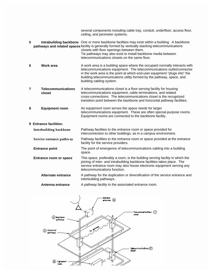
several components including cable tray, conduit, underfloor, access floor, ceiling, and perimeter systems.
5 Intrabuilding backbone pathways and related spaces
One or more backbone facilities may exist within a building. A backbone facility is generally formed by vertically stacking telecommunications closets with floor openings between them. Tie pathways may also exist to install backbone media between telecommunications closets on the same floor.
6 Work area A work area is a building space where the occupant normally interacts with telecommunications equipment. The telecommunications outlet/connector in the work area is the point at which end-user equipment "plugs into" the building telecommunications utility formed by the pathway, space, and building cabling system.
7 Telecommunicationscloset
A telecommunications closet is a floor-serving facility for housing telecommunications equipment, cable terminations, and related cross-connections. The telecommunications closet is the recognized transition point between the backbone and horizontal pathway facilities.
8 Equipment room An equipment room serves the space needs for larger telecommunications equipment. These are often special-purpose rooms. Equipment rooms are connected to the backbone facility.
9 Entrance facilities:
Interbuilding backbone Pathway facilities to the entrance room or space provided for interconnection to other buildings, as in a campus environment.
Service entrance pathway Pathway facilities to the entrance room or space provided at the entrance facility for the service providers.
Entrance point The point of emergence of telecommunications cabling into a building space.
Entrance room or space This space, preferably a room, is the building serving facility in which the joining of inter- and intrabuilding backbone facilities takes place. The service entrance room may also house electronic equipment serving any telecommunications function.
Alternate entrance A pathway for the duplication or diversification of the service entrance and interbuilding pathways.
Antenna entrance A pathway facility to the associated entrance room.
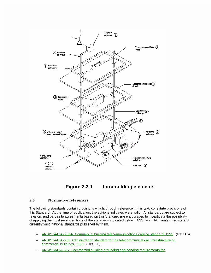
Figure 2.2-1 Intrabuilding elements
2.3 Normative references
The following standards contain provisions which, through reference in this text, constitute provisions of this Standard. At the time of publication, the editions indicated were valid. All standards are subject to revision, and parties to agreements based on this Standard are encouraged to investigate the possibility of applying the most recent editions of the standards indicated below. ANSI and TIA maintain registers of currently valid national standards published by them.
-- ANSI/TIA/EIA-568-A, Commercial building telecommunications cabling standard, 1995. (Ref D.5).
-- ANSI/TIA/EIA-606, Administration standard for the telecommunications infrastructure of commercial buildings, 1993. (Ref D.6).
-- ANSI/TIA/EIA-607, Commercial building grounding and bonding requirements for

telecommunications, 1994. (Ref D.7).
ANSI/TIA/EIA-569-A3 Definitions, abbreviations and acronyms, units
For the purposes of this Standard, the following definitions apply.
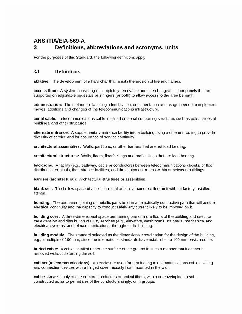
3.1 Definitions ablative: The development of a hard char that resists the erosion of fire and flames.
access floor: A system consisting of completely removable and interchangeable floor panels that are supported on adjustable pedestals or stringers (or both) to allow access to the area beneath.
administration: The method for labelling, identification, documentation and usage needed to implement moves, additions and changes of the telecommunications infrastructure.
aerial cable: Telecommunications cable installed on aerial supporting structures such as poles, sides of buildings, and other structures.
alternate entrance: A supplementary entrance facility into a building using a different routing to provide diversity of service and for assurance of service continuity.
architectural assemblies: Walls, partitions, or other barriers that are not load bearing.
architectural structures: Walls, floors, floor/ceilings and roof/ceilings that are load bearing.
backbone: A facility (e.g., pathway, cable or conductors) between telecommunications closets, or floor distribution terminals, the entrance facilities, and the equipment rooms within or between buildings.
barriers (architectural): Architectural structures or assemblies.
blank cell: The hollow space of a cellular metal or cellular concrete floor unit without factory installed fittings.
bonding: The permanent joining of metallic parts to form an electrically conductive path that will assure electrical continuity and the capacity to conduct safely any current likely to be imposed on it.
building core: A three-dimensional space permeating one or more floors of the building and used for the extension and distribution of utility services (e.g., elevators, washrooms, stairwells, mechanical and electrical systems, and telecommunications) throughout the building.
building module: The standard selected as the dimensional coordination for the design of the building, e.g., a multiple of 100 mm, since the international standards have established a 100 mm basic module.
buried cable: A cable installed under the surface of the ground in such a manner that it cannot be removed without disturbing the soil.
cabinet (telecommunications): An enclosure used for terminating telecommunications cables, wiring and connection devices with a hinged cover, usually flush mounted in the wall.
cable: An assembly of one or more conductors or optical fibers, within an enveloping sheath, constructed so as to permit use of the conductors singly, or in groups.
cable sheath: A covering over the conductor assembly that may include one or more metallic members, strength members, or jackets.
cabling: A combination of all cables, wire, cords, and connecting hardware.
campus: The buildings and grounds having legal contiguous interconnection.
ceiling distribution system: A distribution system that utilizes the space between a suspended or false ceiling and the structural surface above.
cell: A single raceway of a cellular or underfloor duct system.
cellular floor: A floor distribution method in which cables pass through floor cells, constructed of steel or concrete to provide a ready-made raceway for distribution of power and telecommunications cables.
cementitious firestop: A firestopping material that is mixed with water, similar in appearance to mortar. See also: firestopping.
closet (telecommunications): An enclosed space for housing telecommunications equipment, cable terminations, and cross-connect cabling, that is the recognized location of the cross-connect between the backbone and horizontal facilities.
commercial building: A building or portion thereof that is intended for office use.
concrete fill: A minimal-depth concrete pour to encase single-level underfloor duct.
conduit: A raceway of circular cross-section.
NOTE - For the purpose of this Standard the term conduit includes electrical metallic tubing (EMT) or electrical non-metallic tubing.
connecting hardware: A device providing mechanical cable terminations.
consolidation point: A location for interconnection between horizontal cables extending from building pathways and horizontal cables extending into furniture pathways.
core area: See building core.
cross-connect: A facility enabling the termination of cable elements and their interconnection, cross-connection, or both, primarily by means of a patch cord or jumper.
cross-connection: A connection scheme between cabling runs, subsystems, and equipment using patch cords or jumpers that attach to connecting hardware on each end.
crossover: The junction unit at the point of intersection of two cable trays, raceways, or conduit (pathways) on different planes.
device (as related to a work area): An item such as a telephone, personal computer, or a graphic or video terminal.
device box: See outlet box, telecommunications.
distribution duct: A raceway of a rectangular cross-section placed within or just below the finished floor and used to extend the wires or cables to a specific work area.
distribution frame: A structure with terminations for connecting the cabling of a facility in such a manner that interconnection or cross-connections may be readily made.
a) main - when the structure is located at the entrance facility or main cross-connect and serving the building or campus.
b) intermediate - when the structure is located between the main cross-connect and the telecommunications closet.
duct:
a) A single enclosed raceway for wires or cables. See also: conduit, raceway.
b) A single enclosed raceway for wires or cables usually used in soil or concrete.
c) An enclosure in which air is moved. Generally part of the HVAC system of a building.
elastomeric firestop: A firestopping material resembling rubber. See also: firestopping.
emergency power: A stand-alone secondary electrical supply source not dependent upon the primary electrical source.
end user: The owner or user of the premises cabling system.
entrance facility (telecommunications): An entrance to a building for both public and private network service cables (including antennae) including the entrance point at the building wall and continuing to the entrance room or space.
entrance point (telecommunications): The point of emergence of telecommunications conductors through an exterior wall, a concrete floor slab, or from a rigid metal conduit or intermediate metal conduit.
entrance room or space (telecommunications): A space in which the joining of inter- or intrabuilding telecommunications backbone facilities takes place.
NOTE - An entrance room may also serve as an equipment room.
equipment cable; cord: A cable or cable assembly used to connect telecommunications equipment to horizontal or backbone cabling.
equipment room (telecommunications): A centralized space for telecommunications equipment that serves the occupants of the building.
NOTE - An equipment room is considered distinct from a telecommunications closet because of the nature or complexity of the equipment.
false ceiling: See suspended ceiling.
feeder duct: See header duct.
firestop: A material, device, or assembly of parts installed in a cable pathway at a fire-rated wall or floor to prevent passage of flame, smoke or gases through the rated barrier (e.g., between cubicles or separated rooms or spaces).
firestop seals: See firestop system.
firestop system: A specific construction consisting of the material(s) (firestop penetration seals) that fill the opening in the wall or floor assembly and any items that penetrate the wall or floor, such as cables, cable trays, conduit, ducts, pipes, and any termination devices, such as electrical outlet boxes, along with their means of support.
firestopping: The process of installing specialty materials into penetrations in fire-rated barriers to reestablish the integrity of the barrier.
floor slab: That part of a reinforced concrete floor which is carried on beams below.
furniture cluster: A contiguous group of work areas, typically including space divisions, work surfaces, storage and seating.
ground: A conducting connection, whether intentional or accidental, between an electrical circuit (e.g., telecommunications) or equipment and the earth, or to some conducting body that serves in place of earth.
grounding conductor: A conductor used to connect the grounding electrode to the buildings main grounding busbar.
grounding electrode: A conductor, usually a rod, pipe or plate (or group of conductors) in direct contact with the earth for the purpose of providing a low-impedance connection to the earth.
handhole: A structure similar to a small maintenance hole in which it is expected that a person cannot enter to perform work.
header duct; trench, feeder duct: A raceway of rectangular cross-section placed within the floor to tie distribution duct(s) or cell(s) to the telecommunications closet.
home runs: A pathway or cable between two locations without a point of access in between.
horizontal cabling: The cabling between and including the telecommunications outlet/connector and the horizontal cross-connect.
hybrid cable: An assembly of two or more cables, of the same or different types or categories, covered by one overall sheath.
infrastructure (telecommunications): A collection of those telecommunications components, excluding equipment, that together provide the basic support for the distribution of all information within a building or campus.
innerduct: Typically, a nonmetallic pathway within a pathway. Also known as subduct.
insert: An opening into the distribution duct or cell, from which the wires or cables emerge.
insert, afterset: An insert installed after the installation of the concrete floor slab or other flooring material.
insert, preset: An insert installed prior to the installation of the concrete floor slab or other flooring material.
interconnection: A connection scheme that employs connecting hardware for the direct connection of a cable to another cable without a patch cord or jumper.
intermediate cross-connect: A cross-connect between first level and second level backbone cabling.
intumescent firestop: A firestopping material that expands under the influence of heat.
jack header: A raceway similar to a header duct, however, usually provided in short lengths to connect a
quantity of distribution ducts together.
jumper: An assembly of twisted pairs without connectors, used to join telecommunications circuits/links at the cross-connect.
light commercial building: A building or portion thereof that is intended for use with one to four (1-4) non-residential exchange access lines per tenant.
listed: Equipment included in a list published by an organization, acceptable to the authority having jurisdiction, that maintains periodic inspection of production of listed equipment, and whose listing states either that the equipment or material meets appropriate standards or has been tested and found suitable for use in a specified manner.
main cross-connect: A cross-connect for first level backbone cables, entrance cables, and equipment cables.
main distribution frame: See distribution frame.
main terminal room: The location of the cross-connect point of incoming cables from the telecommunications external network and the premises cable system.
maintenance hole (telecommunications): A vault located in the ground or earth as part of an underground duct system and used to facilitate placing, connectorization, and maintenance of cables as well as the placing of associated equipment, in which it is expected that a person will enter to perform work.
NOTE This term was previously called manhole.
media, telecommunications: Wire, cable, or conductors used for telecommunications.
membrane penetration: An opening through only one surface or side of the barrier.
monolithic pour: The single, continuous pouring of a concrete floor and columns of any given floor of a building structure.
multi-user telecommunications outlet assembly: A grouping in one location of several telecommunications outlets/connectors.
network interface device [NID]: The point of connection between networks.
open office: A floor space division provided by furniture, moveable partitions, or other means instead of by building walls.
optical fiber cable: An assembly consisting of one or more optical fibers.
outlet box (telecommunications): A metallic or nonmetallic box mounted within a wall, floor, or ceiling and used to hold telecommunications outlets/connectors or transition devices.
outlet/connector (telecommunications): A connecting device in the work area, on which horizontal cable terminates.
patch cord: A length of cable with connectors on one or both ends used to join telecommunications circuits/links at the cross-connect.
pathway: A facility for the placement of telecommunications cable.

penetration: An opening in a fire-rated barrier.
plenum: A compartment or chamber to which one or more air ducts are connected and that forms part of the air distribution system.
poke-thru system: Penetrations through the fire resistive floor structure to permit the installation of horizontal telecommunications cables.
post-tensioned concrete: A type of reinforced concrete construction in which the steel is put under tension and the concrete under compression, after the concrete has hardened.
pullcord; pullwire: A cord or wire placed within a raceway and used to pull wire and cable through the raceway.
raceway: Any enclosed channel designed for holding wires or cables.
reinforced concrete: A type of construction in which steel (reinforcement) and concrete are combined, with the steel essentially resisting tension and the concrete resisting compression.
service entrance: See entrance facility (telecommunications).
service equipment (power): The necessary equipment, usually consisting of a circuit breaker or switch and fuses, and their accessories, located near the point of entrance of supply conductors to a building or other structure, or an otherwise defined area, and intended to constitute the main control and means of cutoff of the (electrical) supply.
service fitting: An outlet box to house the connections for telecommunications at the user work area. See also: insert.
sheath: See cable sheath.
slab on grade: Concrete floor placed directly on soil, without basement or crawlspace.
sleeve: An opening, usually circular, through the wall, ceiling, or floor to allow the passage of cables.
slot: An opening through a wall, floor, or ceiling, usually rectangular, to allow the passage of cables.
space (telecommunications): An area used for housing the installation and termination of telecommunications equipment and cable, e.g., telecommunications closets, work areas, and maintenance holes/handholes.
splice: A joining of conductors, generally meant to be permanent, generally from separate sheaths.
splice box: A box, located in a pathway run, intended to house a cable splice.
support strand; messenger: A strength element used to carry the weight of the telecommunications cable.
suspended ceiling: A ceiling that creates an area or space between ceiling material and the structure above.
telecommunications: Any transmission, emission, and reception of signs, signals, writings, images, and sounds, that is information of any nature by cable, radio, optical, or other electromagnetic systems.
telecommunications closet: See closet (telecommunications).
telecommunications entrance facility: See entrance facility (telecommunications).
telecommunications equipment room: See equipment room (telecommunications).
telecommunications infrastructure: See infrastructure (telecommunications).
telecommunications media: See media (telecommunications).
telecommunications outlet: See outlet/connector (telecommunications).
telecommunications service entrance: See entrance facility (telecommunications).
telecommunications space: See space (telecommunications).
terminal:
a) A point at which information may enter or leave a communications network.
b) The input-output associated equipment.
c) A device by means of which wires may be connected to each other.
termination hardware: This term is outmoded. See connecting hardware.
through penetration: A continuous opening that passes through both surfaces of a fire-rated barrier.
topology: The physical or logical arrangement of a telecommunications system.
transition point: A location in the horizontal cabling where flat undercarpet cable connects to round cable.
trenchduct: See header duct.
trough: A pathway for the containment of cable, typically provided with a removable cover.
tunnel: An enclosed passageway, usually placed between buildings, for use by people, the distribution utility services, or both.
two-level duct: An underfloor raceway system installed with the header raceways and the distribution raceways on two different planes.
underfloor raceway: A pathway placed within the floor and from which wires and cables emerge to a specific floor area.
usable floor space: Floor space which is capable of being used as a work area.
utility column: An enclosure pathway extending from the ceiling to furniture or to the floor, that forms a pathway for electrical wiring, telecommunications cable, or both.
NOTE - It may also be used to mount or contain connecting hardware.
wire: An individually insulated solid copper conductor, such as the wire used to make twisted wire pairs.
work area; work station: A building space where the occupants interact with telecommunications
terminal equipment.
3.2 Abbreviations and acronyms
ac alternating currentADA Americans with Disabilities ActAHJ authority having jurisdictionAIA American Institute of ArchitectsANSI American National Standards InstituteASTM American Society for Testing and MaterialsAWG American Wire GuageBICSI Building Industry Consulting Service InternationalBOMA Building Owners Managers AssociationCATV community antenna televisionCSA Canadian Standards AssociationCSI Construction Specifications InstituteEIA Electronic Industries AssociationEMI electromagnetic interferenceEMT electrical metallic tubingHDG heavy duty galvanizedHVAC heating, ventilation, and air conditioningIEEE The Institute of Electrical and Electronics EngineersIFMA International Facility Management AssociationLEC local exchange carrierMPD multiple plastic ductNEC National Electrical CodeNEMA National Electrical Manufacturers AssociationNFPA National Fire Protection AssociationPBX private branch exchangeppm parts per millionPVC polyvinylchlorideSTP shielded twisted pairTIA Telecommunications Industry AssociationUL Underwriters Laboratories Inc.UTP unshielded twisted pairUV ultraviolet
3.3 Units
A ampere°C degrees Celsius°F degrees Fahrenheitft feet, footg acceleration of gravityHz hertzin inchkg kilogramkN kilonewtonskPa kilopascalskVA kilovolt-amperes

lbf pound-forcelx luxm meterµg microgramΩ ohm
ANSI/TIA/EIA-569-A4 Horizontal pathways and related spaces
4.1 General
4.1.1 Horizontal pathways are facilities for the installation of telecommunications cable from the telecommunications closet to the work area telecommunications outlet/connector. Horizontal pathways encompass underfloor, access floor, conduit, tray and wireway, ceiling, and perimeter facilities.
4.1.2 Pull boxes and splice boxes may be associated with horizontal pathways. For the purposes of this Standard, both pull boxes and splice boxes are considered as spaces. In addition to some pull box information found in this section, section 5 contains additional information for both pull and splice boxes.
4.1.3 For bonding and grounding of horizontal pathways see the applicable electrical codes and standards, and ANSI/TIA/EIA-607. See informative annex B.
4.1.4 The pathway facility, as a minimum, shall be designed to handle all telecommunications media recognized in ANSI/TIA/EIA-568-A. When determining the size of the pathway, the quantity, size of cables, and bend radius requirements, with an allowance for growth, shall be considered.
4.1.5 Horizontal pathways shall not be located in elevator shafts.
4.1.6 Pathway specifications shall accommodate the applicable seismic zone requirements.
4.1.7 Intrabuilding horizontal pathways shall be installed in dry locations that protect cables from moisture levels that are beyond the intended operating range of inside premises cable (see ANSI/TIA/EIA-568-A). For example, slab-on-grade designs wherein pathways are installed underground or in concrete slabs that are in direct contact with earth, are considered to be wet locations. See ANSI/NFPA-70, Article 100 for definitions of damp, dry and wet locations.
4.2 Underfloor pathways
4.2.1 Underfloor duct
4.2.1.1 General
Underfloor duct systems are pathways for containing cables and wires for services such as telecommunications and electrical power. The system, consisting of distribution (see 4.2.1.5) and header (see 4.2.1.6) ducts, is a network of raceways embedded in concrete. Ducts are rectangular in shape and are produced in at least two different sizes. The ducts may be used in single, double, or triple runs, or may be intermixed in combinations of large and small ducts to provide increased or decreased capacity. Distribution ducts are usually supplied with preset inserts. Ducts extending from the telecommunications closet and under passageways may be installed without inserts. Access or handhole units shall be placed in duct runs to permit changes in direction and provide access for pulling cables.
4.2.1.2 Types (underfloor duct)
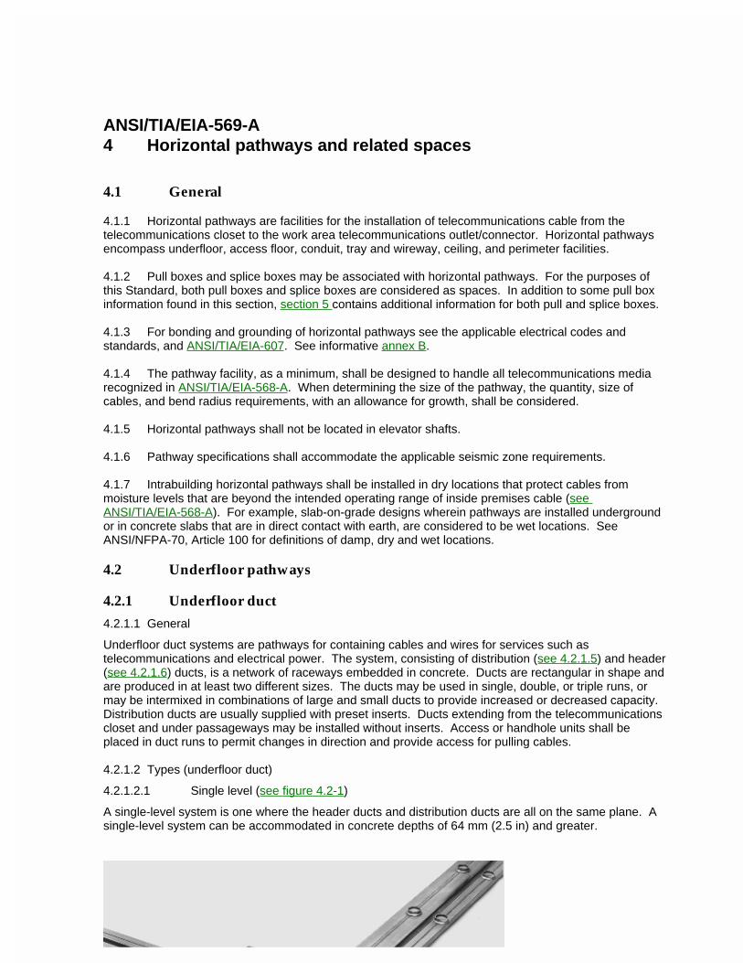
4.2.1.2.1 Single level (see figure 4.2-1)
A single-level system is one where the header ducts and distribution ducts are all on the same plane. A single-level system can be accommodated in concrete depths of 64 mm (2.5 in) and greater.
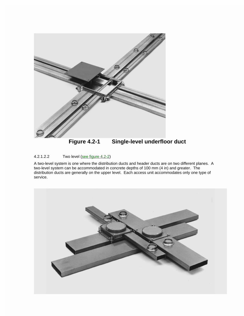
Figure 4.2-1 Single-level underfloor duct
4.2.1.2.2 Two level (see figure 4.2-2)
A two-level system is one where the distribution ducts and header ducts are on two different planes. A two-level system can be accommodated in concrete depths of 100 mm (4 in) and greater. The distribution ducts are generally on the upper level. Each access unit accommodates only one type of service.
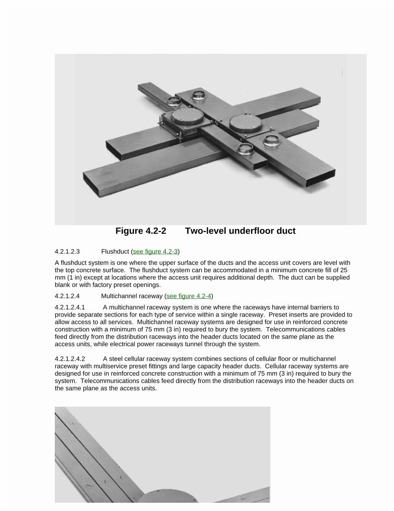
Figure 4.2-2 Two-level underfloor duct
4.2.1.2.3 Flushduct (see figure 4.2-3)
A flushduct system is one where the upper surface of the ducts and the access unit covers are level with the top concrete surface. The flushduct system can be accommodated in a minimum concrete fill of 25 mm (1 in) except at locations where the access unit requires additional depth. The duct can be supplied blank or with factory preset openings.
4.2.1.2.4 Multichannel raceway (see figure 4.2-4)
4.2.1.2.4.1 A multichannel raceway system is one where the raceways have internal barriers to provide separate sections for each type of service within a single raceway. Preset inserts are provided to allow access to all services. Multichannel raceway systems are designed for use in reinforced concrete construction with a minimum of 75 mm (3 in) required to bury the system. Telecommunications cables feed directly from the distribution raceways into the header ducts located on the same plane as the access units, while electrical power raceways tunnel through the system.
4.2.1.2.4.2 A steel cellular raceway system combines sections of cellular floor or multichannel raceway with multiservice preset fittings and large capacity header ducts. Cellular raceway systems are designed for use in reinforced concrete construction with a minimum of 75 mm (3 in) required to bury the system. Telecommunications cables feed directly from the distribution raceways into the header ducts on the same plane as the access units.
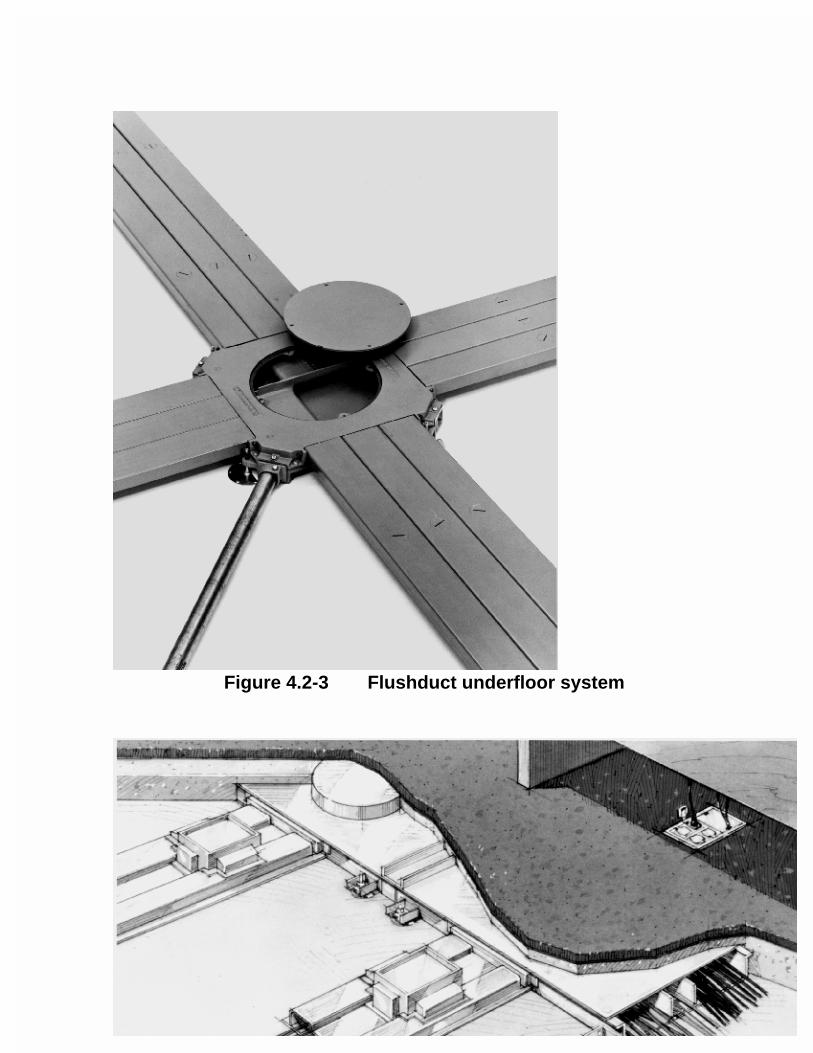
Figure 4.2-3 Flushduct underfloor system
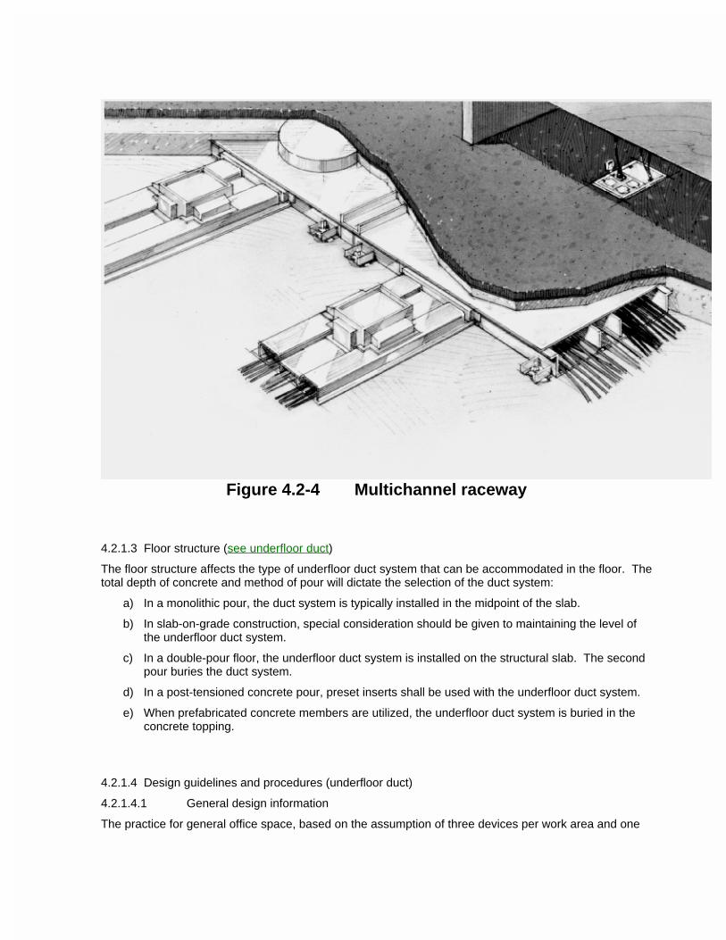
Figure 4.2-4 Multichannel raceway
4.2.1.3 Floor structure (see underfloor duct)
The floor structure affects the type of underfloor duct system that can be accommodated in the floor. The total depth of concrete and method of pour will dictate the selection of the duct system:
a) In a monolithic pour, the duct system is typically installed in the midpoint of the slab.
b) In slab-on-grade construction, special consideration should be given to maintaining the level of the underfloor duct system.
c) In a double-pour floor, the underfloor duct system is installed on the structural slab. The second pour buries the duct system.
d) In a post-tensioned concrete pour, preset inserts shall be used with the underfloor duct system.
e) When prefabricated concrete members are utilized, the underfloor duct system is buried in the concrete topping.
4.2.1.4 Design guidelines and procedures (underfloor duct)
4.2.1.4.1 General design information
The practice for general office space, based on the assumption of three devices per work area and one
work area per 10 m2 (100 ft2), is to provide 650 mm2 (1 in2) of cross-sectional underfloor duct area per 10 m2 (100 ft2) of usable floor space. This practice applies to both header and distribution duct. Where it is known that the number of devices per work area is greater, or the work area allocation density is greater than the rule, the sizing shall be increased accordingly.
4.2.1.4.2 Specific design information
In office buildings, service shall be provided by locating the distribution duct runs 1520-1825 mm (5-6 ft) apart at the midpoint of the building module. This spacing provides good coverage and flexibility for work area placement without compromising the integrity of the floor structure. The runs adjacent to exterior building walls shall be located 450-600 mm (18-24 in) from the walls or column lines. After the parallel distribution runs have been established, the cross runs of header duct and access units are determined by the density of the service requirements and the area to be supplied from each telecommunications closet. In general, 18 m (60 ft) spacing for access units is adequate. Provisions shall be made to connect the system to the telecommunications closets by a number of enclosed header duct home runs or a trenchduct. Telecommunications closets shall be located as close as practicable to the floor areas they serve in order to provide adequate feed.
4.2.1.5 Distribution duct (underfloor duct)
The distribution ducts are those ducts of an underfloor duct system from which the cables emerge to a specific work area. Flushduct and buried duct (single and two-level) are usually provided with preset inserts on 600 mm (24 in) centers. Blank duct is supplied without preset inserts.
4.2.1.6 Header duct (underfloor duct)
4.2.1.6.1 General
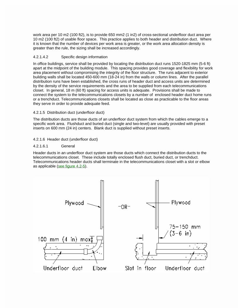
Header ducts in an underfloor duct system are those ducts which connect the distribution ducts to the telecommunications closet. These include totally enclosed flush duct, buried duct, or trenchduct. Telecommunications header ducts shall terminate in the telecommunications closet with a slot or elbow as applicable (see figure 4.2-5).
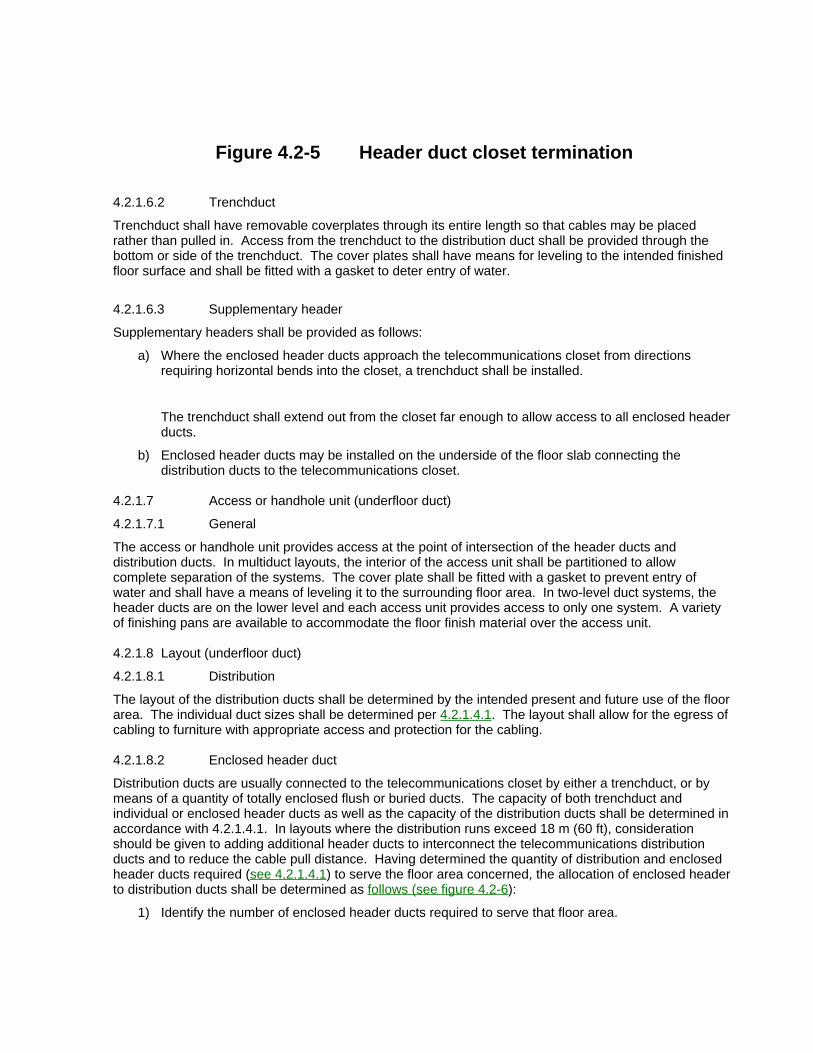
Figure 4.2-5 Header duct closet termination
4.2.1.6.2 Trenchduct
Trenchduct shall have removable coverplates through its entire length so that cables may be placed rather than pulled in. Access from the trenchduct to the distribution duct shall be provided through the bottom or side of the trenchduct. The cover plates shall have means for leveling to the intended finished floor surface and shall be fitted with a gasket to deter entry of water.
4.2.1.6.3 Supplementary header
Supplementary headers shall be provided as follows:
a) Where the enclosed header ducts approach the telecommunications closet from directions requiring horizontal bends into the closet, a trenchduct shall be installed.
The trenchduct shall extend out from the closet far enough to allow access to all enclosed header ducts.
b) Enclosed header ducts may be installed on the underside of the floor slab connecting the distribution ducts to the telecommunications closet.
4.2.1.7 Access or handhole unit (underfloor duct)
4.2.1.7.1 General
The access or handhole unit provides access at the point of intersection of the header ducts and distribution ducts. In multiduct layouts, the interior of the access unit shall be partitioned to allow complete separation of the systems. The cover plate shall be fitted with a gasket to prevent entry of water and shall have a means of leveling it to the surrounding floor area. In two-level duct systems, the header ducts are on the lower level and each access unit provides access to only one system. A variety of finishing pans are available to accommodate the floor finish material over the access unit.
4.2.1.8 Layout (underfloor duct)
4.2.1.8.1 Distribution
The layout of the distribution ducts shall be determined by the intended present and future use of the floor area. The individual duct sizes shall be determined per 4.2.1.4.1. The layout shall allow for the egress of cabling to furniture with appropriate access and protection for the cabling.
4.2.1.8.2 Enclosed header duct
Distribution ducts are usually connected to the telecommunications closet by either a trenchduct, or by means of a quantity of totally enclosed flush or buried ducts. The capacity of both trenchduct and individual or enclosed header ducts as well as the capacity of the distribution ducts shall be determined in accordance with 4.2.1.4.1. In layouts where the distribution runs exceed 18 m (60 ft), consideration should be given to adding additional header ducts to interconnect the telecommunications distribution ducts and to reduce the cable pull distance. Having determined the quantity of distribution and enclosed header ducts required (see 4.2.1.4.1) to serve the floor area concerned, the allocation of enclosed header to distribution ducts shall be determined as follows (see figure 4.2-6):
1) Identify the number of enclosed header ducts required to serve that floor area.
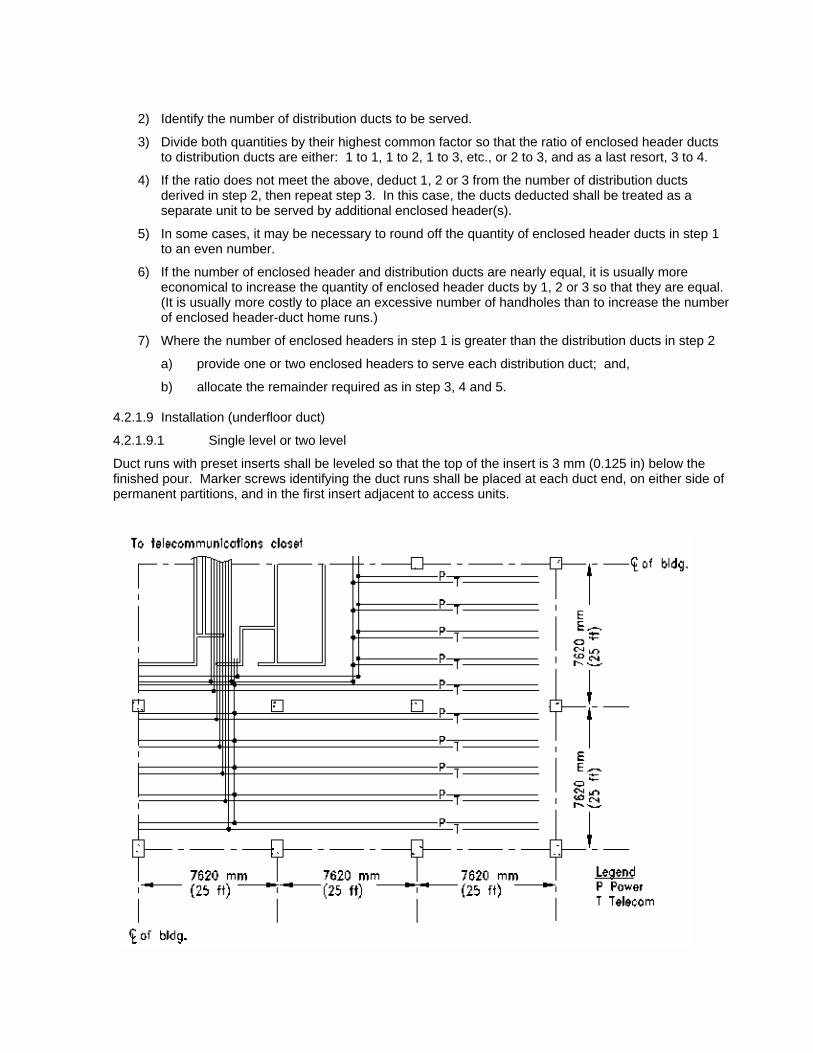
2) Identify the number of distribution ducts to be served.
3) Divide both quantities by their highest common factor so that the ratio of enclosed header ducts to distribution ducts are either: 1 to 1, 1 to 2, 1 to 3, etc., or 2 to 3, and as a last resort, 3 to 4.
4) If the ratio does not meet the above, deduct 1, 2 or 3 from the number of distribution ducts derived in step 2, then repeat step 3. In this case, the ducts deducted shall be treated as a separate unit to be served by additional enclosed header(s).
5) In some cases, it may be necessary to round off the quantity of enclosed header ducts in step 1 to an even number.
6) If the number of enclosed header and distribution ducts are nearly equal, it is usually more economical to increase the quantity of enclosed header ducts by 1, 2 or 3 so that they are equal. (It is usually more costly to place an excessive number of handholes than to increase the number of enclosed header-duct home runs.)
7) Where the number of enclosed headers in step 1 is greater than the distribution ducts in step 2
a) provide one or two enclosed headers to serve each distribution duct; and,
b) allocate the remainder required as in step 3, 4 and 5.
4.2.1.9 Installation (underfloor duct)
4.2.1.9.1 Single level or two level
Duct runs with preset inserts shall be leveled so that the top of the insert is 3 mm (0.125 in) below the finished pour. Marker screws identifying the duct runs shall be placed at each duct end, on either side of permanent partitions, and in the first insert adjacent to access units.
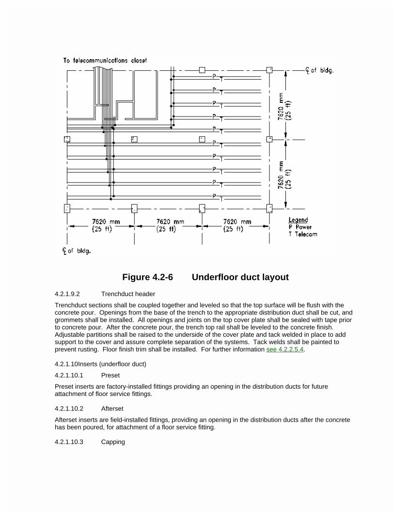
Figure 4.2-6 Underfloor duct layout
4.2.1.9.2 Trenchduct header
Trenchduct sections shall be coupled together and leveled so that the top surface will be flush with the concrete pour. Openings from the base of the trench to the appropriate distribution duct shall be cut, and grommets shall be installed. All openings and joints on the top cover plate shall be sealed with tape prior to concrete pour. After the concrete pour, the trench top rail shall be leveled to the concrete finish. Adjustable partitions shall be raised to the underside of the cover plate and tack welded in place to add support to the cover and assure complete separation of the systems. Tack welds shall be painted to prevent rusting. Floor finish trim shall be installed. For further information see 4.2.2.5.4.
4.2.1.10Inserts (underfloor duct)
4.2.1.10.1 Preset
Preset inserts are factory-installed fittings providing an opening in the distribution ducts for future attachment of floor service fittings.
4.2.1.10.2 Afterset
Afterset inserts are field-installed fittings, providing an opening in the distribution ducts after the concrete has been poured, for attachment of a floor service fitting.
4.2.1.10.3 Capping
Capping is the plugging of a preset or afterset insert when a floor service fitting is removed.
4.2.1.11Service fittings (underfloor duct)
4.2.1.11.1 General
Service fittings are available in several different types that serve from one to many different services. If electrical power is one of the services in a combined fitting, the fitting shall be fully partitioned.
4.2.1.11.2 Dedicated in-floor
Dedicated in-floor service fittings are boxes installed in the concrete slab (prior to the pour) on a predetermined grid of the distribution layout, providing access to all services. When services are required, assemblies containing the connecting devices for each system are installed along with a floor finish egress plate.
4.2.2 Cellular floor
4.2.2.1 General
A cellular floor is an underfloor system in which its structural members act as the formwork to support the concrete floor slab, with the cells becoming the distribution raceways. The header ducts are set at right angles to the direction of the cells and are contained within the concrete pour.
4.2.2.2 Types (cellular floor)
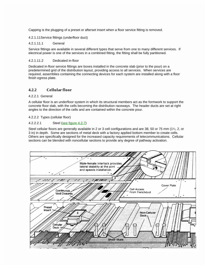
4.2.2.2.1 Steel (see figure 4.2-7)
Steel cellular floors are generally available in 2 or 3 cell configurations and are 38, 50 or 75 mm (1½, 2, or 3 in) in depth. Some are sections of metal deck with a factory applied bottom member to create cells. Others are specifically designed for the increased capacity requirements of telecommunications. Cellular sections can be blended with noncellular sections to provide any degree of pathway activation.
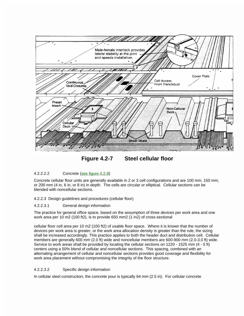
Figure 4.2-7 Steel cellular floor
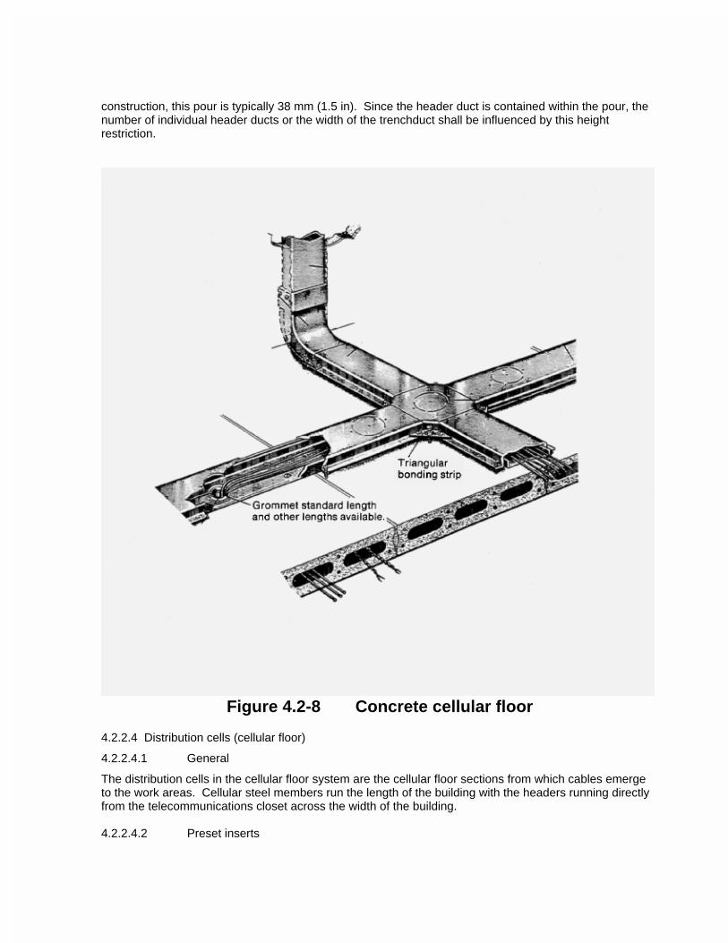
4.2.2.2.2 Concrete (see figure 4.2-8)
Concrete cellular floor units are generally available in 2 or 3 cell configurations and are 100 mm, 150 mm, or 200 mm (4 in, 6 in, or 8 in) in depth. The cells are circular or elliptical. Cellular sections can be blended with noncellular sections.
4.2.2.3 Design guidelines and procedures (cellular floor)
4.2.2.3.1 General design information
The practice for general office space, based on the assumption of three devices per work area and one work area per 10 m2 (100 ft2), is to provide 650 mm2 (1 in2) of cross-sectional
cellular floor cell area per 10 m2 (100 ft2) of usable floor space. Where it is known that the number of devices per work area is greater, or the work area allocation density is greater than the rule, the sizing shall be increased accordingly. This practice applies to both the header duct and distribution cell. Cellular members are generally 600 mm (2.0 ft) wide and noncellular members are 600-900 mm (2.0-3.0 ft) wide. Service to work areas shall be provided by locating the cellular sections on 1220 - 1525 mm (4 - 5 ft) centers using a 50% blend of cellular and noncellular sections. This spacing, combined with an alternating arrangement of cellular and noncellular sections provides good coverage and flexibility for work area placement without compromising the integrity of the floor structure.
4.2.2.3.2 Specific design information
In cellular steel construction, the concrete pour is typically 64 mm (2.5 in). For cellular concrete
construction, this pour is typically 38 mm (1.5 in). Since the header duct is contained within the pour, the number of individual header ducts or the width of the trenchduct shall be influenced by this height restriction.
Figure 4.2-8 Concrete cellular floor
4.2.2.4 Distribution cells (cellular floor)
4.2.2.4.1 General
The distribution cells in the cellular floor system are the cellular floor sections from which cables emerge to the work areas. Cellular steel members run the length of the building with the headers running directly from the telecommunications closet across the width of the building.
4.2.2.4.2 Preset inserts
Steel distribution cells can be provided with single or multiservice type preset inserts. The insert is provided as a blank unit to be activated as required. Center-to-center spacing shall be a minimum of 600 mm (24 in) along the length of the cell.
4.2.2.4.3 Blank cell
A blank cell is the hollow space of a cellular metal or cellular concrete floor unit without factory-installed fittings. Blank distribution cells are supplied without inserts. Access to blank cells shall be provided by core drilling through the concrete and cutting through the top surface of the cell.
4.2.2.5 Header duct (cellular floor)
4.2.2.5.1 General
Header ducts in a cellular floor system are those ducts which connect the distribution cells to the telecommunications closet. To ensure long-term accessibility and serviceability, enclosed headers shall be provided as separate ducts for electrical power and telecommunications services, or as a single trenchduct equipped with a barrier for each service. Access units shall be spaced to fall directly above the selected cells. See general design information for proper sizing of header duct. Jack-header ducts shall be provided to maintain coverage of floor areas that would otherwise be isolated, e.g., by stairwells or columns.
4.2.2.5.2 Flushduct (see figure 4.2-8)
Flush-header duct used in concrete cellular floor systems shall be a two-piece type. The bottom section shall be a channel designed with factory prepunched holes that align with the appropriate preallocated cells. A hole shall be core drilled through the concrete to the cell, and fitted with a grommet. The top section shall be a "top-hat" design that fits over the bottom section and shall have a leveling means along the side flanges to level the top surface flush with the final concrete floor level. Access units shall be provided in the top section, prelocated over each opening into the cells. Each service shall be contained in a separate header duct.
4.2.2.5.3 Buried duct
A buried-type header duct used in steel cellular floor systems shall be totally enclosed. Prepunched holes shall be provided in the bottom of the header duct with factory-installed adjustable access units on top. These units shall be designed to align with the appropriate preallocated cells. A hole shall be made through the top of the steel cell and fitted with a grommet. Each service shall be contained in separate header duct.
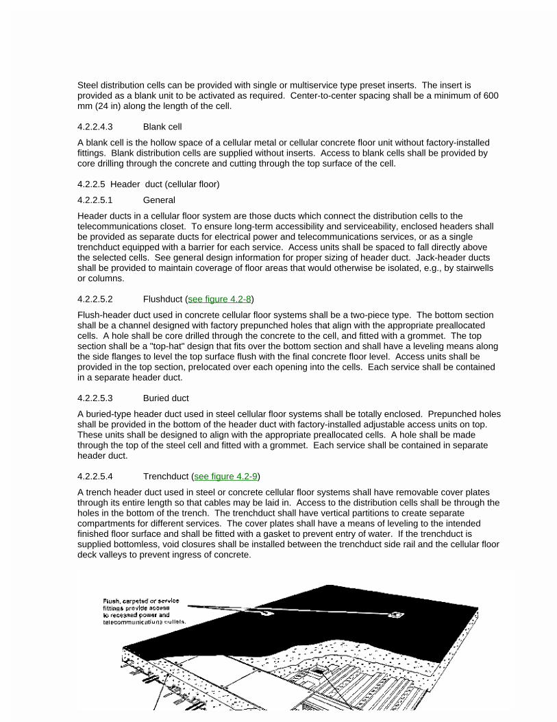
4.2.2.5.4 Trenchduct (see figure 4.2-9)
A trench header duct used in steel or concrete cellular floor systems shall have removable cover plates through its entire length so that cables may be laid in. Access to the distribution cells shall be through the holes in the bottom of the trench. The trenchduct shall have vertical partitions to create separate compartments for different services. The cover plates shall have a means of leveling to the intended finished floor surface and shall be fitted with a gasket to prevent entry of water. If the trenchduct is supplied bottomless, void closures shall be installed between the trenchduct side rail and the cellular floor deck valleys to prevent ingress of concrete.
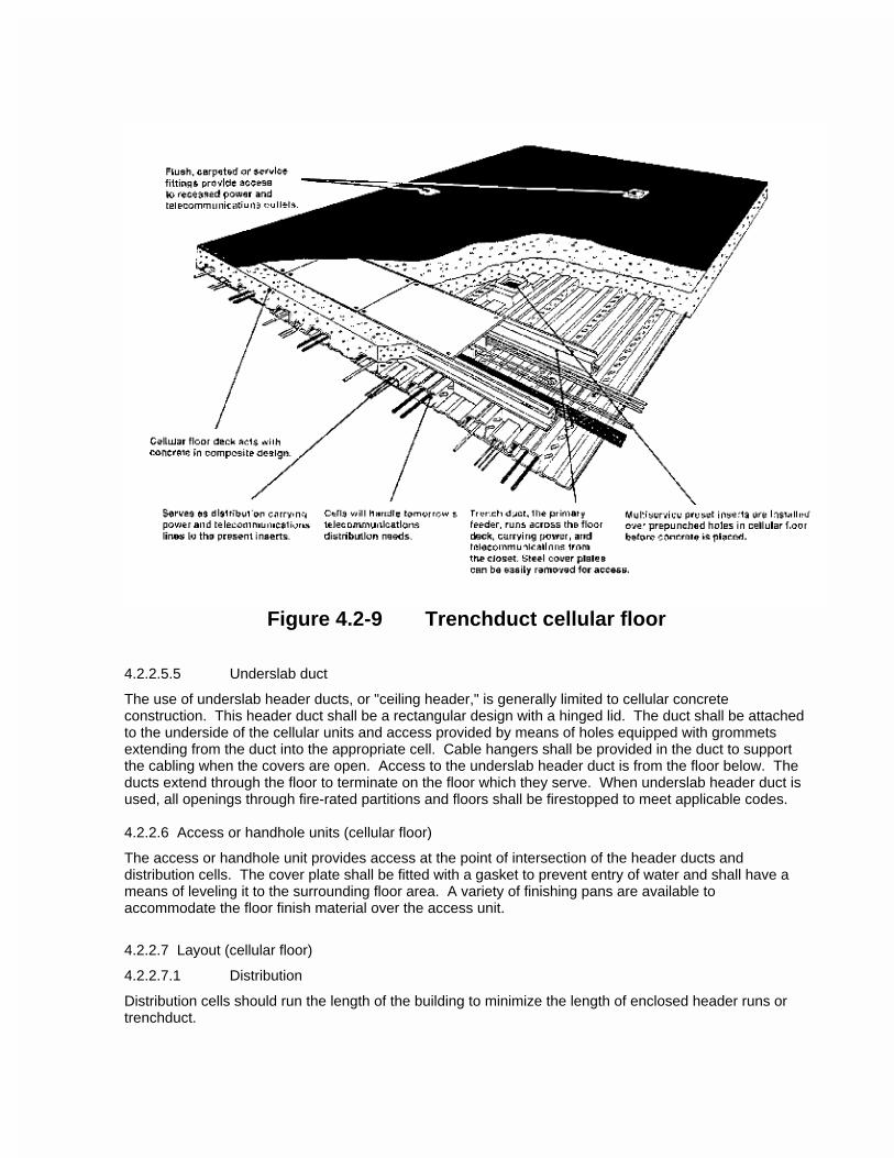
Figure 4.2-9 Trenchduct cellular floor
4.2.2.5.5 Underslab duct
The use of underslab header ducts, or "ceiling header," is generally limited to cellular concrete construction. This header duct shall be a rectangular design with a hinged lid. The duct shall be attached to the underside of the cellular units and access provided by means of holes equipped with grommets extending from the duct into the appropriate cell. Cable hangers shall be provided in the duct to support the cabling when the covers are open. Access to the underslab header duct is from the floor below. The ducts extend through the floor to terminate on the floor which they serve. When underslab header duct is used, all openings through fire-rated partitions and floors shall be firestopped to meet applicable codes.
4.2.2.6 Access or handhole units (cellular floor)
The access or handhole unit provides access at the point of intersection of the header ducts and distribution cells. The cover plate shall be fitted with a gasket to prevent entry of water and shall have a means of leveling it to the surrounding floor area. A variety of finishing pans are available to accommodate the floor finish material over the access unit.
4.2.2.7 Layout (cellular floor)
4.2.2.7.1 Distribution
Distribution cells should run the length of the building to minimize the length of enclosed header runs or trenchduct.
4.2.2.7.2 Allocating distribution cells
Where the cellular unit profile provides different cross-sectional areas for the cells, the largest cell shall be allocated for telecommunications and the smallest for electrical power.
4.2.2.7.3 Enclosed header duct
In layouts where the length of distribution cells exceed 18 m (60 ft), consideration should be given to adding additional enclosed header ducts to interconnect the telecommunications distribution cells and to reduce the pull distance. Having determined the quantity of distribution cells and enclosed header ducts required (see 4.2.2.3.1) to serve the floor area concerned, the allocation of enclosed header to distribution cells shall be determined as follows:
1) Identify the number of enclosed header ducts required to serve that floor area.
2) Identify the number of distribution cells to be served.
3) Divide both quantities by their highest common factor so that the ratio of enclosed header ducts to distribution ducts are either: 1 to 1, 1 to 2, 1 to 3, etc., or 2 to 3, and as a last resort, 3 to 4.
4) If the ratio does not meet the above, deduct 1, 2 or 3 from the number of distribution cells in derived step 2, then repeat step 3. In this case, the cells deducted shall be treated as a separate unit to be served by additional header(s).
5) In some cases, it may be necessary to round off the quantity of enclosed header ducts in step 1 to an even number.
6) If the number of enclosed header ducts and distribution cells are nearly equal, it is usually more economical to increase the quantity of enclosed header ducts by 1, 2 or 3 so that they are equal. (It is usually more costly to place an excessive number of handholes than to increase the number of enclosed header-duct home runs.)
7) Where the number of enclosed headers in step 1 is greater than the distribution cells in step 2
a) provide one or two enclosed headers to serve each distribution cell; and,
b) allocate the remainder required as in step 3, 4 and 5.
4.2.2.8 Installation (cellular floor)
4.2.2.8.1 Two level cellular steel
The header duct shall be installed on top of the floor cells with the access units centered over the cells to be activated. Ducts shall be secured to the cells by hold-down straps or tabs fastened to the unactivated cells or to the valley between the cells. Marker assemblies shall be installed at the end of the cells and on either side of permanent partitions. After the concrete is set, access shall be provided and fitted with a grommet between the header duct and the cell.
4.2.2.8.2 Trenchduct header
Trenchduct sections shall be leveled so that the top surface will be level with the concrete finish. Openings from the base of the trench to the appropriate distribution cell shall be cut and fitted with a grommet. All openings and joints on the top cover plate shall be sealed with tape prior to concrete pour. After the pour, final leveling of the trench top rail shall be done. Adjustable partitions shall be raised to the underside of the cover plate and tack-welded in place to support the cover and assure complete separation of the services. Tack welds shall be painted with a rust-preventing paint. Floor finish trim shall be installed.
4.2.2.8.3 Flushduct cellular concrete
The bottom portion of the duct shall be installed on top of the floor cells with the prepunched holes centered over the cells to be activated. These holes shall be fitted with a grommet. The duct shall be fastened to the cellular unit with concrete fasteners installed through the bottom portion of the duct into the top of the cellular unit between the cells. Access holes shall be provided. The top portion of the duct shall be installed over the bottom portion and leveled to the finished concrete floor. After concrete has set, the knockouts in the top surface of the duct shall be removed, and access plates shall be installed.
4.2.2.8.4 Underslab duct
The top portion of the duct shall be installed on the underside of the floor cells with the prepunched holes centered under the cells to be activated. These holes shall be drilled and fitted with a grommet. The duct shall be fastened to the cellular unit with concrete fasteners installed through the top portion of the duct into the bottom of the cellular unit between the cells. Cable hangers shall be provided in the duct to support cabling when covers are open. When underslab header duct is used, all openings through fire-rated partitions and floors shall be firestopped to meet applicable codes.
4.2.2.8.5 Telecommunications closet termination
Telecommunications header ducts shall terminate in the closet with a slot or elbow as applicable.
4.2.2.9 Inserts (cellular floor)
4.2.2.9.1 Preset insert
A preset insert is a device that provides an opening into the distribution cell for attachment of a floor service fitting. They are either factory- or field-installed prior to the concrete pour.
4.2.2.9.2 Afterset insert
An afterset insert is a field-installed device that provides an opening into the distribution cell, after the concrete has been poured, for attachment of a floor service fitting.
4.2.2.9.3 Capping
Capping is the plugging of a preset or afterset insert when a floor service fitting is removed.
4.2.2.9.4 Multiservice insert
A multiservice insert (preset or afterset) is a single device that provides an opening to the distribution cell for activation of more than one service at a work area.
4.2.2.10Service fittings (cellular floor)
4.2.2.10.1 Above floor
Above-floor service fittings are available in several different designs and sizes that accommodate the various services. If electrical power is one of the services in a combined fitting, the fitting shall be fully partitioned.
4.2.2.10.2 Dedicated in-floor
Dedicated in-floor service fittings are boxes installed in the concrete slab (prior to the pour) on a predetermined grid of the distribution layout, providing access to all services. When services are required, assemblies containing the connecting devices for each system are installed along with a floor-finish egress plate.
4.2.2.10.3 Floor boxes (single- and multiservice) are boxes installed in concrete floors (prior to the pour) on a predetermined grid, providing access for all services. Services are distributed from these boxes via either flush service covers or above-floor services fittings. Service fittings are available for
several different services. If electrical power is one of the services in a combined fitting, the fitting shall be fully partitioned.
4.3 Access floor
4.3.1 General
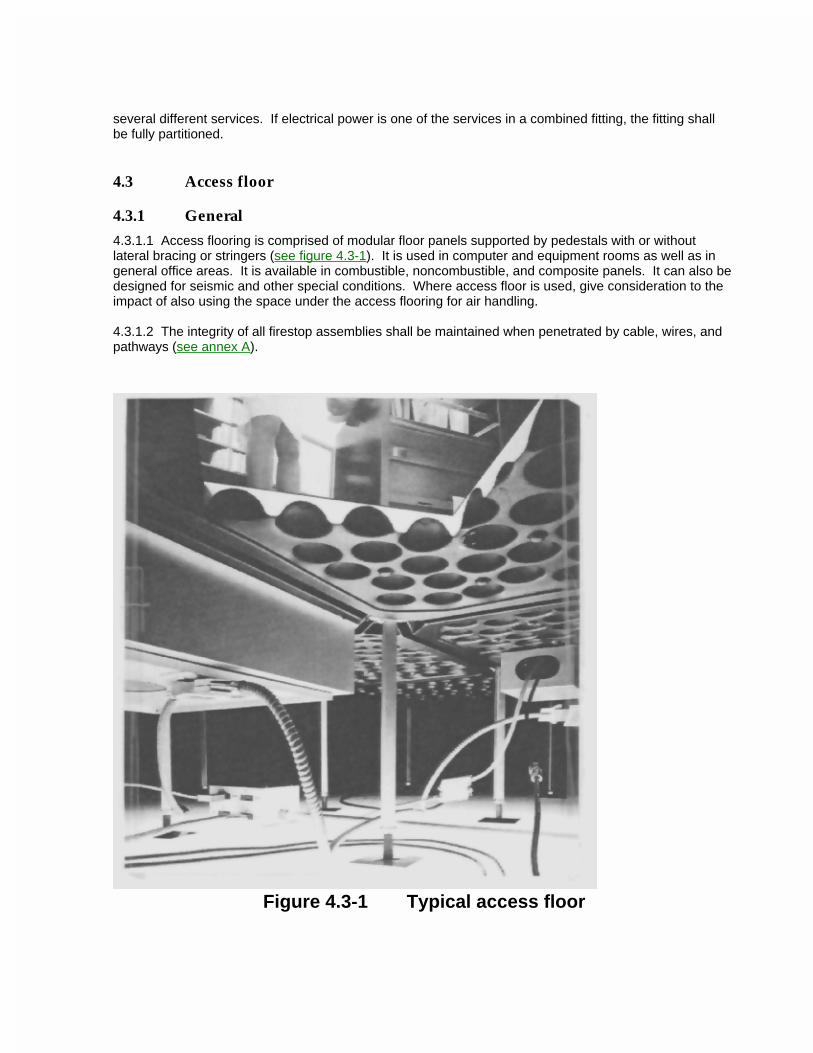
4.3.1.1 Access flooring is comprised of modular floor panels supported by pedestals with or without lateral bracing or stringers (see figure 4.3-1). It is used in computer and equipment rooms as well as in general office areas. It is available in combustible, noncombustible, and composite panels. It can also be designed for seismic and other special conditions. Where access floor is used, give consideration to the impact of also using the space under the access flooring for air handling.
4.3.1.2 The integrity of all firestop assemblies shall be maintained when penetrated by cable, wires, and pathways (see annex A).
Figure 4.3-1 Typical access floor
4.3.1.3 Types
4.3.1.3.1 Stringered
Stringered systems have lateral bracing between the pedestal supports. Used in equipment rooms, stringered systems provide additional support to facilitate frequent removal and replacement of unrestrained panels. Stringers shall be bolted or snapped to the pedestal head and provide additional support to the panels and lateral stability to the system.
4.3.1.3.2 Free standing
Freestanding types consist of panels that are supported solely by the pedestal supports with no mechanical fastening. These shall be restricted to low finished floor heights (e.g., 300 mm (12 in) and less).
4.3.1.3.3 Cornerlock
Cornerlock types, as in free standing, have panels supported only by pedestals, and the panels shall be mechanically fastened to the pedestal heads at each corner. This method adds the stability necessary in a general office installation.
4.3.1.4 Loading performance
Performance information for static, dynamic and impact loading conditions are provided in annex B.
4.3.1.5 Test methods for access floor
Panels and understructure shall be tested and meet the requirements of Ceilings and Interior Systems Construction Association (CISCA) test methods (Ref D.12).
4.3.1.6 Fire rating
The floor panels exclusive of covering shall have a Class A flame spread when tested in accordance with ASTM E 84 (Ref D.8) and NFPA 255 (Ref D.16). Where cabling is not contained in conduit, panels shall be fabricated completely of noncombustible materials. Flame spread integrity shall not be affected when the panel is cut.
4.3.2 Building structure
4.3.2.1 Depressed slab
In new construction, the area to receive access flooring shall be depressed. The depth of depression shall equal the height of the finished access floor.
4.3.2.2 Normal slab
Where the slab is not depressed, consideration should be made for ramps or steps to the access floor. Building codes shall be followed for both ramp and step assemblies.
4.3.3 Design guidelines and procedures for access flooring
4.3.3.1 Work areas
Penetrations through the floor shall be designed for the type and number of work areas and may be located anywhere on the access floor. Service outlets shall not be placed in traffic areas or where they create a hazard to the occupants.
4.3.3.2 Specific design information
4.3.3.2.1 Minimum heightWhere access floor is used in general office areas, the minimum finished-floor height should be 150 mm (6 in). When used in a telecommunications equipment room environment, the minimum finished floor height should be 300 mm (12 in) and shall not be less than 150 mm (6 in). Telecommunications closet flooring is typically the same height as the office area served.
NOTE - Where cable tray or other facilities (e.g., power distribution) is used under general office area access floor, a minimum of 203 mm (8 in) should be considered.
4.3.3.2.2 Cable management
A method of physical management for major runs of cabling shall be provided such as:
a) dedicated routes;
b) raceway primary distribution;
c) zone distribution system (see 4.6.2.4);
d) cable tray (see 4.5).
4.3.4 Installation
4.3.4.1 Layout
The access floor layout shall be determined prior to the installation of any equipment or telecommunications cabling.
4.3.4.2 Linkage to telecommunications closet
The telecommunications closet and access floor area served should be located adjacent to each other, connected by threaded sleeves or conduits. If not adjacent, other means of linkage shall be provided. Sizing of the interconnecting pathways shall be based on the design criteria for that specific type of pathway.
4.3.4.3 Service fittings
Service fittings for access flooring consist of single or combined slab-mounted, and single or combined dedicated fittings. The manufacturer shall be consulted to ensure compatibility.
4.3.4.4 Grounding and bonding access flooring
Grounding and bonding of access flooring is not directly covered by electrical codes except for dedicated information technology equipment rooms. For grounding and bonding of access flooring metal parts see manufacturers instructions and applicable electrical codes and standards. Also see annex B.5.
4.4 Conduit
4.4.1 General
4.4.1.1 Types of conduit
Conduit types include
-- Electrical metallic and nonmetallic tubing;
-- Nonmetallic flexible conduit and nonmetallic flexible tubing;
-- Rigid metal conduit;
-- Rigid nonmetallic conduit; and
-- Other types.
Conduit shall be of the type permitted under the appropriate electrical codes. If flexible metal conduit is used, the length should be less than 6 m (20 ft) for each run and the conduit selected should minimize cable abrasion during the pulling in operation.
NOTE - For zone conduit distribution, refer to ceiling pathways (4.6) and figure 4.6-2.
4.4.1.2 Use of conduit
The use of conduit as a horizontal raceway system for telecommunications cabling is only considered when: it is required by code, outlet locations are permanent, device densities are low, and flexibility is not required. In-floor conduit systems are especially inflexible as they are usually buried in concrete.
4.4.2 Design guidelines
4.4.2.1 Minimum requirements
Minimum requirements for installed conduits, such as support, end protection, and continuity, are found in appropriate electrical codes.
4.4.2.2 Length
No section of conduit shall be longer than 30 m (100 ft) between pull points.
4.4.2.3 Bends
4.4.2.3.1 No section of conduit shall contain more than two 90o bends, or equivalent, between pull points (e.g., outlet boxes, telecommunications closets, or pull boxes.) If there is a reverse (U-shaped) bend in the section, a pull box shall be installed.
4.4.2.3.2 The inside radius of a bend in conduit shall be at least 6 times the internal diameter. Bends in the conduit shall not contain any kinks or other discontinuities that may have a detrimental effect on the cable sheath during cable pulling operations.
4.4.2.4 Sizing
Conduits should be sized per table 4.4-1.
4.4.2.5 Conduit runs
4.4.2.5.1 Any single conduit run extending from a telecommunications closet shall not serve more than three outlet boxes.
4.4.2.5.2 Conduits should be incrementally increased in size from the furthest outlet box toward the telecommunications closet.
Table 4.4-1 Conduit sizing
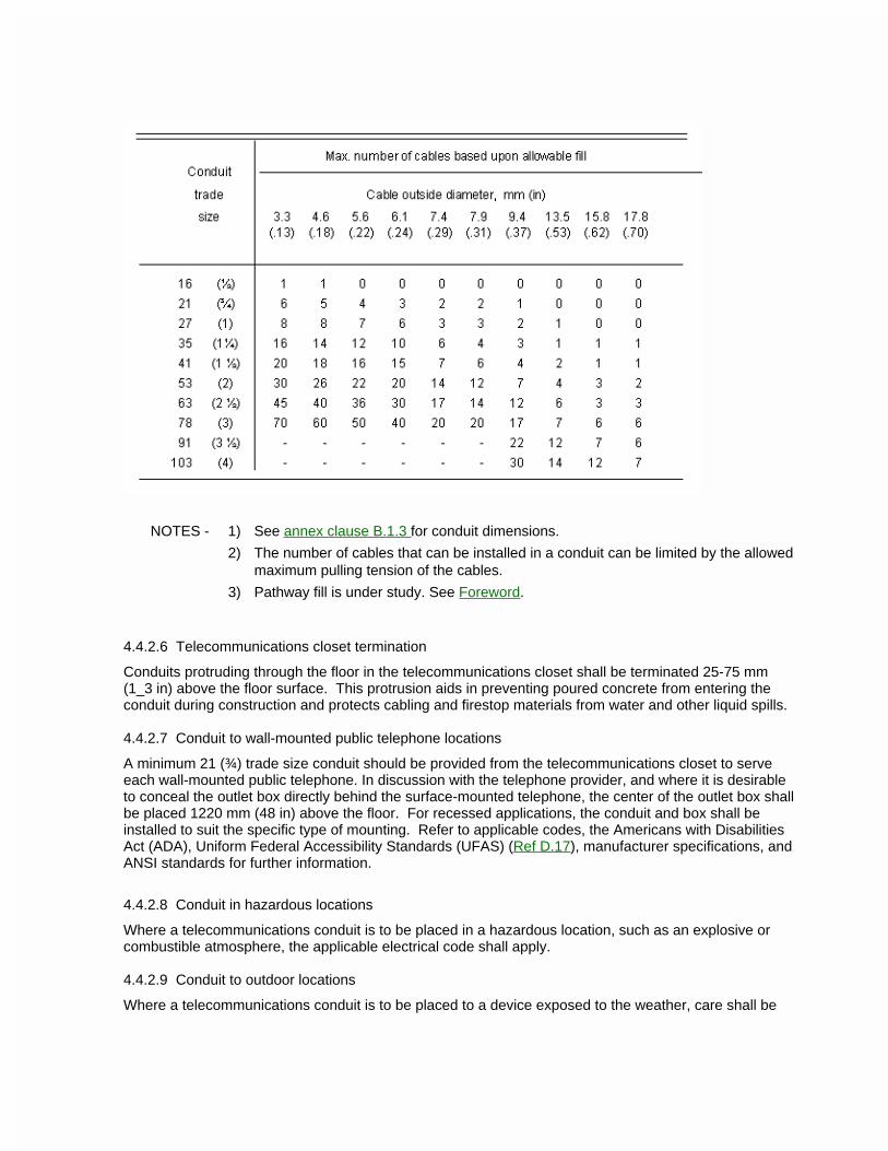
NOTES - 1) See annex clause B.1.3 for conduit dimensions.
2) The number of cables that can be installed in a conduit can be limited by the allowed maximum pulling tension of the cables.
3) Pathway fill is under study. See Foreword.
4.4.2.6 Telecommunications closet termination
Conduits protruding through the floor in the telecommunications closet shall be terminated 25-75 mm (1_3 in) above the floor surface. This protrusion aids in preventing poured concrete from entering the conduit during construction and protects cabling and firestop materials from water and other liquid spills.
4.4.2.7 Conduit to wall-mounted public telephone locations
A minimum 21 (¾) trade size conduit should be provided from the telecommunications closet to serve each wall-mounted public telephone. In discussion with the telephone provider, and where it is desirable to conceal the outlet box directly behind the surface-mounted telephone, the center of the outlet box shall be placed 1220 mm (48 in) above the floor. For recessed applications, the conduit and box shall be installed to suit the specific type of mounting. Refer to applicable codes, the Americans with Disabilities Act (ADA), Uniform Federal Accessibility Standards (UFAS) (Ref D.17), manufacturer specifications, and ANSI standards for further information.
4.4.2.8 Conduit in hazardous locations
Where a telecommunications conduit is to be placed in a hazardous location, such as an explosive or combustible atmosphere, the applicable electrical code shall apply.
4.4.2.9 Conduit to outdoor locations
Where a telecommunications conduit is to be placed to a device exposed to the weather, care shall be
taken to prevent the ingress of moisture. Care shall also be taken to ensure that moisture will not collect in low points, freeze and damage the cable. Nonmetallic conduit shall be UV resistant and marked accordingly.
4.4.3 Installation
4.4.3.1 Conduit termination
Conduits shall be reamed to eliminate sharp edges. Metallic conduit shall be terminated with an insulated bushing.
4.4.3.2 Conduit system identification
Refer to ANSI/TIA/EIA-606 for administration of the conduit system.
4.4.3.3 Pull strings
Pull string or rope shall be placed in installed conduits.
4.4.4 Outlet boxes
Outlet boxes shall be no smaller than 50 mm wide, 75 mm high, 64 mm deep (2 in, 3 in, 2.5 in). This box will accommodate one or two 21 (¾) trade size conduits. Where a larger conduit is required, the box size shall be increased accordingly. A maximum 35 (1¼) trade size conduit will require a 120 mm x 120 mm x 64 mm (4-11/16 in x 4-11/16 in x 2_½ in) outlet box. Where 27 (1) trade size conduit is required, a 100 mm x 100 mm x 57 mm (4 in x 4 in x 2¼ in) box should be used. Specialty boxes may be used in place of the above as appropriate. Supports for attaching the outlet box and a suitable coverplate shall be provided.
4.4.5 Pull boxes
4.4.5.1 Pull boxes shall be used for the following purposes:
a) Fishing the conduit run.
b) Installing a pull string or cable.
c) Pulling the cable to the box and then looping the cable to be pulled into the next length of conduit.
4.4.5.2 When pull boxes are used within horizontal distribution, they shall comply with the pull box requirements of clause 5.2.3.
4.5 Cable trays and wireways 4.5.1 General
4.5.1.1 Cable trays and wireways are prefabricated rigid structures for the housing and protecting cables or conductors, that are pulled or laid in place after the pathway has been installed as a complete system. These pathways shall be installed in accordance with the applicable electrical code.
4.5.1.2 Types
Following are typical examples of cable trays and wireways.
a) Channel cable tray: A structure with a one-piece ventilated bottom or solid bottom channel section not exceeding 150 mm (6 in) wide.
b) Ladder cable tray: A structure consisting of two side rails connected by individual transverse
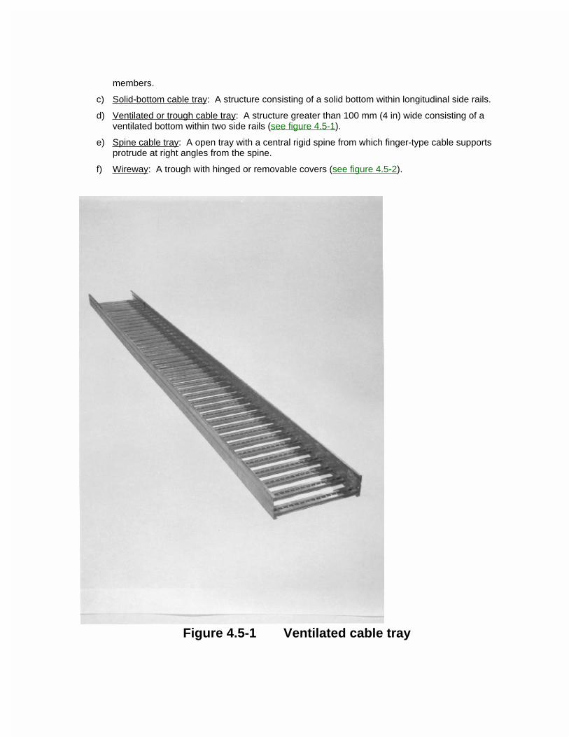
members.
c) Solid-bottom cable tray: A structure consisting of a solid bottom within longitudinal side rails.
d) Ventilated or trough cable tray: A structure greater than 100 mm (4 in) wide consisting of a ventilated bottom within two side rails (see figure 4.5-1).
e) Spine cable tray: A open tray with a central rigid spine from which finger-type cable supports protrude at right angles from the spine.
f) Wireway: A trough with hinged or removable covers (see figure 4.5-2).
Figure 4.5-1 Ventilated cable tray
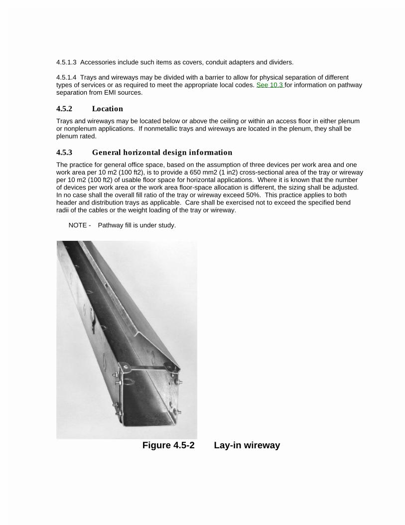
4.5.1.3 Accessories include such items as covers, conduit adapters and dividers.
4.5.1.4 Trays and wireways may be divided with a barrier to allow for physical separation of different types of services or as required to meet the appropriate local codes. See 10.3 for information on pathway separation from EMI sources.
4.5.2 Location
Trays and wireways may be located below or above the ceiling or within an access floor in either plenum or nonplenum applications. If nonmetallic trays and wireways are located in the plenum, they shall be plenum rated.
4.5.3 General horizontal design information
The practice for general office space, based on the assumption of three devices per work area and one work area per 10 m2 (100 ft2), is to provide a 650 mm2 (1 in2) cross-sectional area of the tray or wireway per 10 m2 (100 ft2) of usable floor space for horizontal applications. Where it is known that the number of devices per work area or the work area floor-space allocation is different, the sizing shall be adjusted. In no case shall the overall fill ratio of the tray or wireway exceed 50%. This practice applies to both header and distribution trays as applicable. Care shall be exercised not to exceed the specified bend radii of the cables or the weight loading of the tray or wireway.
NOTE - Pathway fill is under study.
Figure 4.5-2 Lay-in wireway
4.5.4 Support
Cable trays may be supported by three basic support devices: cantilever brackets, trapeze, and individual rod suspension; they also may be supported by spacers in access floor applications to elevate the trays above the floor surface. Supports should be located where practicable so that connections between sections of the tray fall between the support point and the quarter section of the span. The support centers shall be in accordance with the load and span for the applicable class as specified in the electrical code. A support should be placed within 600 mm (2 ft) on each side of any connection to a fitting. Wireways shall be supported on 1500 mm (5 ft) centers unless designed for greater lengths.
4.5.5 Accessories
Fittings used include elbows, reducers, crossovers and tees. These fittings may be used to change direction or size of the tray or wireway.
4.5.6 Installation
4.5.6.1 The inside of the cable tray or wireway shall be free of burrs, sharp edges or projections that can damage cable insulation. Abrasive supports (e.g., threaded rod) shall have the portion within the tray protected with a smooth, non-scratching covering so that cable can be pulled without physical damage. When a wireway passes through a partition or wall, it shall be an unbroken length. Installation of telecommunications cables shall not exceed the fill requirements stated in clause 4.5.3. Openings in fire-rated walls, floors and ceilings shall be properly firestopped (see annex A). Barriers between power and telecommunications cables shall be installed per electrical code. Cable trays and wireways shall not be used as walkways or ladders unless specifically designed and installed for that purpose. 4.5.6.2 A minimum of 300 mm (12 in) access headroom shall be provided and maintained above a cable tray. Care shall be taken to ensure that other building components (e.g., air conditioning ducts) do not restrict access to trays or wireways.
4.6 Ceiling pathway
4.6.1 Ceiling pathway/space
4.6.1.1 Ceiling areas are sometimes used as pathways for telecommunications cables as well as spaces for connecting hardware. Rules covering installations in both air plenums and nonplenum hollow-ceiling systems are found in the applicable electrical and building codes.
4.6.1.2 ConsiderationsCeiling distribution systems shall meet the following conditions:
a) Inaccessible ceiling areas, such as lock-in type ceiling tiles, drywall or plaster, shall not be used as distribution pathways.
b) The ceiling tiles are of the removable or lay-in type.
c) Adequate and suitable space is available in the ceiling area for the distribution layout recommended.
d) Raceways are provided where required by applicable codes or design.
4.6.2 Design guidelines
4.6.2.1 Planning
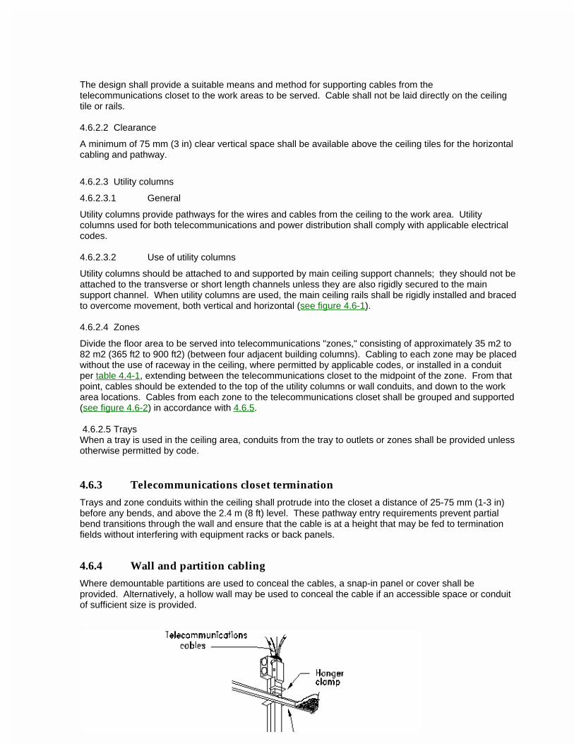
The design shall provide a suitable means and method for supporting cables from the telecommunications closet to the work areas to be served. Cable shall not be laid directly on the ceiling tile or rails.
4.6.2.2 Clearance
A minimum of 75 mm (3 in) clear vertical space shall be available above the ceiling tiles for the horizontal cabling and pathway.
4.6.2.3 Utility columns
4.6.2.3.1 General
Utility columns provide pathways for the wires and cables from the ceiling to the work area. Utility columns used for both telecommunications and power distribution shall comply with applicable electrical codes.
4.6.2.3.2 Use of utility columns
Utility columns should be attached to and supported by main ceiling support channels; they should not be attached to the transverse or short length channels unless they are also rigidly secured to the main support channel. When utility columns are used, the main ceiling rails shall be rigidly installed and braced to overcome movement, both vertical and horizontal (see figure 4.6-1).
4.6.2.4 Zones
Divide the floor area to be served into telecommunications "zones," consisting of approximately 35 m2 to 82 m2 (365 ft2 to 900 ft2) (between four adjacent building columns). Cabling to each zone may be placed without the use of raceway in the ceiling, where permitted by applicable codes, or installed in a conduit per table 4.4-1, extending between the telecommunications closet to the midpoint of the zone. From that point, cables should be extended to the top of the utility columns or wall conduits, and down to the work area locations. Cables from each zone to the telecommunications closet shall be grouped and supported (see figure 4.6-2) in accordance with 4.6.5.
4.6.2.5 TraysWhen a tray is used in the ceiling area, conduits from the tray to outlets or zones shall be provided unless otherwise permitted by code.
4.6.3 Telecommunications closet termination
Trays and zone conduits within the ceiling shall protrude into the closet a distance of 25-75 mm (1-3 in) before any bends, and above the 2.4 m (8 ft) level. These pathway entry requirements prevent partial bend transitions through the wall and ensure that the cable is at a height that may be fed to termination fields without interfering with equipment racks or back panels.
4.6.4 Wall and partition cabling
Where demountable partitions are used to conceal the cables, a snap-in panel or cover shall be provided. Alternatively, a hollow wall may be used to conceal the cable if an accessible space or conduit of sufficient size is provided.
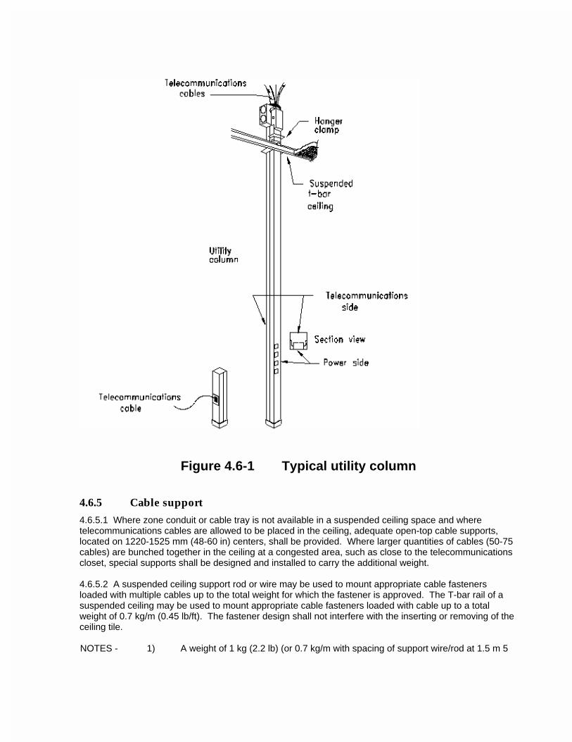
Figure 4.6-1 Typical utility column
4.6.5 Cable support
4.6.5.1 Where zone conduit or cable tray is not available in a suspended ceiling space and where telecommunications cables are allowed to be placed in the ceiling, adequate open-top cable supports, located on 1220-1525 mm (48-60 in) centers, shall be provided. Where larger quantities of cables (50-75 cables) are bunched together in the ceiling at a congested area, such as close to the telecommunications closet, special supports shall be designed and installed to carry the additional weight.
4.6.5.2 A suspended ceiling support rod or wire may be used to mount appropriate cable fasteners loaded with multiple cables up to the total weight for which the fastener is approved. The T-bar rail of a suspended ceiling may be used to mount appropriate cable fasteners loaded with cable up to a total weight of 0.7 kg/m (0.45 lb/ft). The fastener design shall not interfere with the inserting or removing of the ceiling tile.
NOTES - 1) A weight of 1 kg (2.2 lb) (or 0.7 kg/m with spacing of support wire/rod at 1.5 m 5
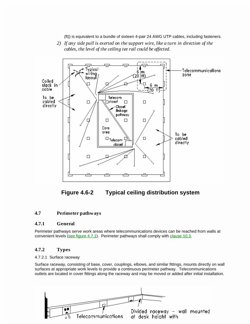
(ft)) is equivalent to a bundle of sixteen 4-pair 24 AWG UTP cables, including fasteners.
2) If any side pull is exerted on the support wire, like a turn in direction of the cables, the level of the ceiling tee rail could be affected.
Figure 4.6-2 Typical ceiling distribution system
4.7 Perimeter pathways
4.7.1 General
Perimeter pathways serve work areas where telecommunications devices can be reached from walls at convenient levels (see figure 4.7.1). Perimeter pathways shall comply with clause 10.3.
4.7.2 Types
4.7.2.1 Surface raceway
Surface raceway, consisting of base, cover, couplings, elbows, and similar fittings, mounts directly on wall surfaces at appropriate work levels to provide a continuous perimeter pathway. Telecommunications outlets are located in cover fittings along the raceway and may be moved or added after initial installation.
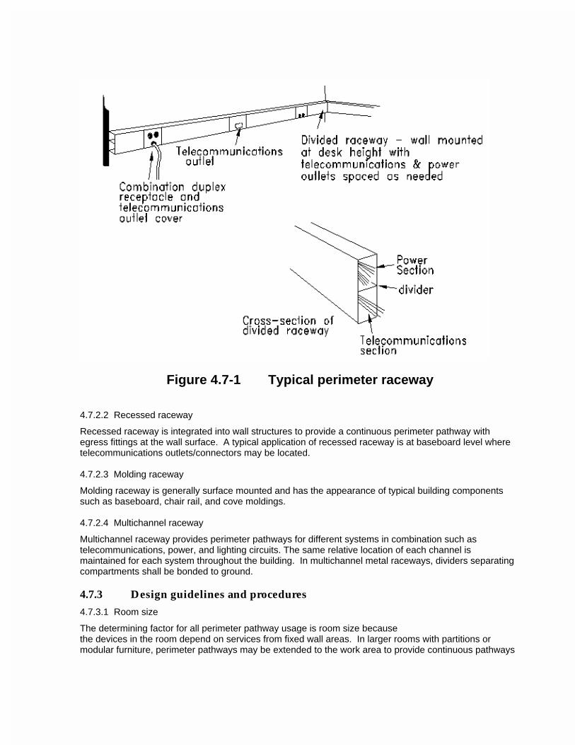
Figure 4.7-1 Typical perimeter raceway
4.7.2.2 Recessed raceway
Recessed raceway is integrated into wall structures to provide a continuous perimeter pathway with egress fittings at the wall surface. A typical application of recessed raceway is at baseboard level where telecommunications outlets/connectors may be located.
4.7.2.3 Molding raceway
Molding raceway is generally surface mounted and has the appearance of typical building components such as baseboard, chair rail, and cove moldings.
4.7.2.4 Multichannel raceway
Multichannel raceway provides perimeter pathways for different systems in combination such as telecommunications, power, and lighting circuits. The same relative location of each channel is maintained for each system throughout the building. In multichannel metal raceways, dividers separating compartments shall be bonded to ground.
4.7.3 Design guidelines and procedures
4.7.3.1 Room size
The determining factor for all perimeter pathway usage is room size becausethe devices in the room depend on services from fixed wall areas. In larger rooms with partitions or modular furniture, perimeter pathways may be extended to the work area to provide continuous pathways
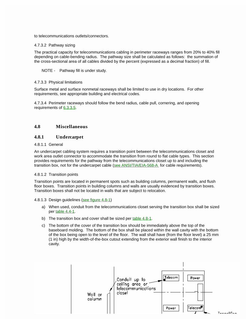
to telecommunications outlets/connectors.
4.7.3.2 Pathway sizing
The practical capacity for telecommunications cabling in perimeter raceways ranges from 20% to 40% fill depending on cable-bending radius. The pathway size shall be calculated as follows: the summation of the cross-sectional area of all cables divided by the percent (expressed as a decimal fraction) of fill.
NOTE - Pathway fill is under study.
4.7.3.3 Physical limitations
Surface metal and surface nonmetal raceways shall be limited to use in dry locations. For other requirements, see appropriate building and electrical codes.
4.7.3.4 Perimeter raceways should follow the bend radius, cable pull, cornering, and opening requirements of 6.3.3.5.
4.8 Miscellaneous
4.8.1 Undercarpet
4.8.1.1 General
An undercarpet cabling system requires a transition point between the telecommunications closet and work area outlet connector to accommodate the transition from round to flat cable types. This section provides requirements for the pathway from the telecommunications closet up to and including the transition box, not for the undercarpet cable (see ANSI/TIA/EIA-568-A for cable requirements).
4.8.1.2 Transition points
Transition points are located in permanent spots such as building columns, permanent walls, and flush floor boxes. Transition points in building columns and walls are usually evidenced by transition boxes. Transition boxes shall not be located in walls that are subject to relocation.
4.8.1.3 Design guidelines (see figure 4.8-1)
a) When used, conduit from the telecommunications closet serving the transition box shall be sized per table 4.4-1.
b) The transition box and cover shall be sized per table 4.8-1.
c) The bottom of the cover of the transition box should be immediately above the top of the baseboard molding. The bottom of the box shall be placed within the wall cavity with the bottom of the box being open to the level of the floor. The wall shall have (from the floor level) a 25 mm (1 in) high by the width-of-the-box cutout extending from the exterior wall finish to the interior cavity.
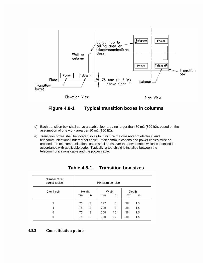
Figure 4.8-1 Typical transition boxes in columns
d) Each transition box shall serve a usable floor area no larger than 80 m2 (800 ft2), based on the assumption of one work area per 10 m2 (100 ft2).
e) Transition boxes shall be located so as to minimize the crossover of electrical and telecommunications undercarpet cable. If telecommunications and power cables must be crossed, the telecommunications cable shall cross over the power cable which is installed in accordance with applicable code. Typically, a top shield is installed between the telecommunications cable and the power cable.
Table 4.8-1 Transition box sizes
4.8.2 Consolidation points
4.8.2.1 Consolidation points shall be located in fully accessible, permanent locations such as building columns and permanent walls. Consolidation points shall not be located in any obstructed area, and shall not be installed in furniture systems unless that unit of furniture is permanently secured to the building structure. The use of suspended ceiling space or access floor space for consolidation points may be acceptable, provided that the space is accessible without moving building fixtures, equipment, or heavy furniture (e.g., file cabinets weighing 45 kg (100 lb) or more), and without disturbing building occupants. In all cases, the use of consolidation points in plenum spaces used for environmental air shall conform to applicable building codes. Consolidation points shall be administered in the same manner as telecommunications cabling, hardware, pathways and spaces as described in ANSI/TIA/EIA-606.
4.8.2.2 Design guidelines
Each consolidation point shall serve a usable floor area no larger than the telecommunications zone (see 4.6.2.4). Refer to clause 6.3 for additional information.
4.8.3 Multi-user telecommunications outlet assemblies
4.8.3.1 Multi-user telecommunications outlet assemblies shall be located in fully accessible permanent locations such as building columns walls or furniture. These assemblies shall not be located in ceiling spaces, under access flooring, or any obstructed area, and shall not be installed in furniture systems unless that unit of furniture is permanently secured to the building structure. The telecommunications multi-user outlet assembly shall be mounted in such a way that it does not obstruct the intended pathway cabling capacity. Multi-user telecommunications outlet assemblies shall be administered in the same manner as telecommunications cabling, hardware, pathways and spaces as described in ANSI/TIA/EIA-606.
4.8.3.2 Design guidelines
Design guides for multi-user telecommunications outlet assemblies shall follow the same guidelines in 4.8.2.2 for consolidation points.
4.8.4 Interstud
"Interstud" pathways consist of the hollow spaces between the studs and the holes within the studs. The pathway should not have any sharp edges or objects that will cause damage to the cable sheath. Any sharp edges or objects that exist shall be provided with bushings as required.
4.8.5 Overfloor raceway
Overfloor raceways are not covered by this Standard.
4.8.6 Exposed cabling
Telecommunications cabling intended to be exposed to view is not covered by this Standard.
4.8.7 Poke-thru
Poke-thru systems are not covered by this Standard.
4.8.8 Curtain wall
Pathways shall not be routed through gaps between the floor or ceiling structure and the curtain wall.
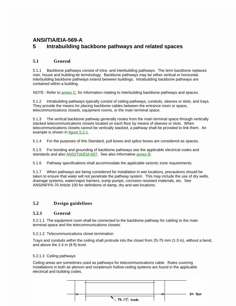
ANSI/TIA/EIA-569-A5 Intrabuilding backbone pathways and related spaces
5.1 General
5.1.1 Backbone pathways consist of intra- and interbuilding pathways. The term backbone replaces riser, house and building-tie terminology. Backbone pathways may be either vertical or horizontal. Interbuilding backbone pathways extend between buildings. Intrabuilding backbone pathways are contained within a building.
NOTE - Refer to annex C for information relating to interbuilding backbone pathways and spaces.
5.1.2 Intrabuilding pathways typically consist of ceiling pathways, conduits, sleeves or slots, and trays. They provide the means for placing backbone cables between the entrance room or space, telecommunications closets, equipment rooms, or the main terminal space.
5.1.3 The vertical backbone pathway generally routes from the main terminal space through vertically stacked telecommunications closets located on each floor by means of sleeves or slots. When telecommunications closets cannot be vertically stacked, a pathway shall be provided to link them. An example is shown in figure 5.2-1.
5.1.4 For the purposes of this Standard, pull boxes and splice boxes are considered as spaces.
5.1.5 For bonding and grounding of backbone pathways see the applicable electrical codes and standards and also ANSI/TIA/EIA-607. See also informative annex B.
5.1.6 Pathway specifications shall accommodate the applicable seismic zone requirements.
5.1.7 When pathways are being considered for installation in wet locations, precautions should be taken to ensure that water will not penetrate the pathway system. This may include the use of dry wells, drainage systems, water/vapor barriers, sump pumps, corrosion resistant materials, etc. See ANSI/NFPA-70 Article 100 for definitions of damp, dry and wet locations.
5.2 Design guidelines
5.2.1 General
5.2.1.1 The equipment room shall be connected to the backbone pathway for cabling to the main terminal space and the telecommunications closets.
5.2.1.2 Telecommunications closet termination
Trays and conduits within the ceiling shall protrude into the closet from 25-75 mm (1-3 in), without a bend, and above the 2.4 m (8 ft) level.
5.2.1.3 Ceiling pathways
Ceiling areas are sometimes used as pathways for telecommunications cable. Rules covering installations in both air plenum and nonplenum hollow-ceiling systems are found in the applicable electrical and building codes.
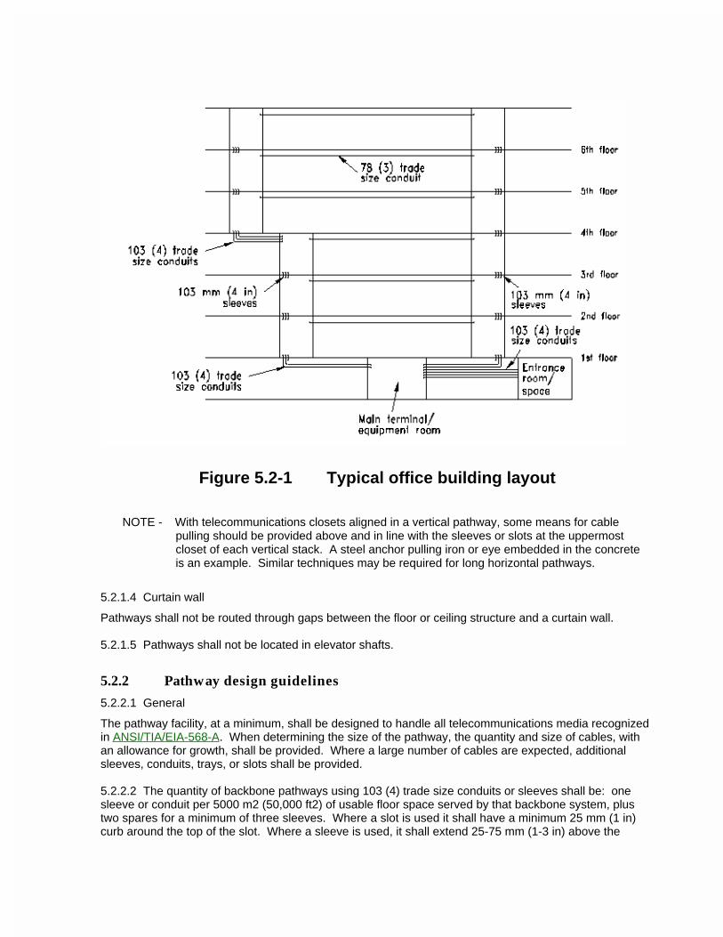
Figure 5.2-1 Typical office building layout
NOTE - With telecommunications closets aligned in a vertical pathway, some means for cable pulling should be provided above and in line with the sleeves or slots at the uppermost closet of each vertical stack. A steel anchor pulling iron or eye embedded in the concrete is an example. Similar techniques may be required for long horizontal pathways.
5.2.1.4 Curtain wall
Pathways shall not be routed through gaps between the floor or ceiling structure and a curtain wall.
5.2.1.5 Pathways shall not be located in elevator shafts.
5.2.2 Pathway design guidelines
5.2.2.1 General
The pathway facility, at a minimum, shall be designed to handle all telecommunications media recognized in ANSI/TIA/EIA-568-A. When determining the size of the pathway, the quantity and size of cables, with an allowance for growth, shall be provided. Where a large number of cables are expected, additional sleeves, conduits, trays, or slots shall be provided.
5.2.2.2 The quantity of backbone pathways using 103 (4) trade size conduits or sleeves shall be: one sleeve or conduit per 5000 m2 (50,000 ft2) of usable floor space served by that backbone system, plus two spares for a minimum of three sleeves. Where a slot is used it shall have a minimum 25 mm (1 in) curb around the top of the slot. Where a sleeve is used, it shall extend 25-75 mm (1-3 in) above the
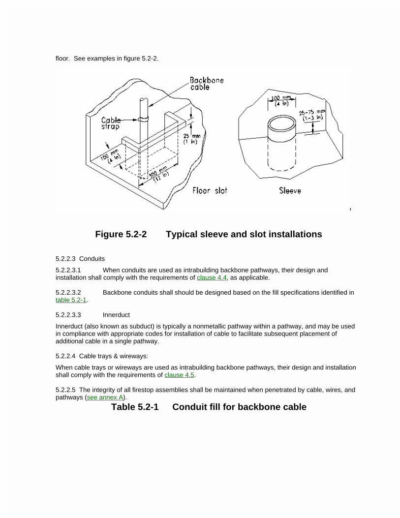
floor. See examples in figure 5.2-2.
Figure 5.2-2 Typical sleeve and slot installations
5.2.2.3 Conduits
5.2.2.3.1 When conduits are used as intrabuilding backbone pathways, their design and installation shall comply with the requirements of clause 4.4, as applicable.
5.2.2.3.2 Backbone conduits shall should be designed based on the fill specifications identified in table 5.2-1.
5.2.2.3.3 Innerduct
Innerduct (also known as subduct) is typically a nonmetallic pathway within a pathway, and may be used in compliance with appropriate codes for installation of cable to facilitate subsequent placement of additional cable in a single pathway.
5.2.2.4 Cable trays & wireways:
When cable trays or wireways are used as intrabuilding backbone pathways, their design and installation shall comply with the requirements of clause 4.5.
5.2.2.5 The integrity of all firestop assemblies shall be maintained when penetrated by cable, wires, and pathways (see annex A).
Table 5.2-1 Conduit fill for backbone cable
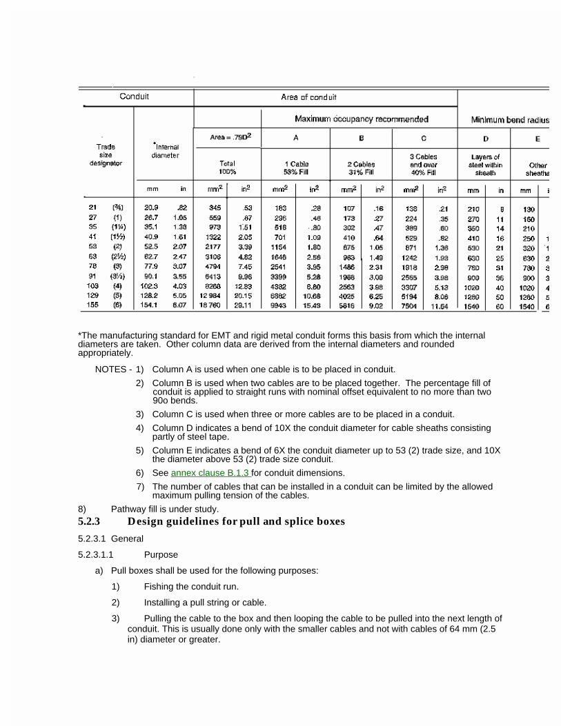
*The manufacturing standard for EMT and rigid metal conduit forms this basis from which the internal diameters are taken. Other column data are derived from the internal diameters and rounded appropriately.
NOTES - 1) Column A is used when one cable is to be placed in conduit.
2) Column B is used when two cables are to be placed together. The percentage fill of conduit is applied to straight runs with nominal offset equivalent to no more than two 90o bends.
3) Column C is used when three or more cables are to be placed in a conduit.
4) Column D indicates a bend of 10X the conduit diameter for cable sheaths consisting partly of steel tape.
5) Column E indicates a bend of 6X the conduit diameter up to 53 (2) trade size, and 10X the diameter above 53 (2) trade size conduit.
6) See annex clause B.1.3 for conduit dimensions.
7) The number of cables that can be installed in a conduit can be limited by the allowed maximum pulling tension of the cables.
8) Pathway fill is under study. 5.2.3 Design guidelines for pull and splice boxes
5.2.3.1 General
5.2.3.1.1 Purpose
a) Pull boxes shall be used for the following purposes:
1) Fishing the conduit run.
2) Installing a pull string or cable.
3) Pulling the cable to the box and then looping the cable to be pulled into the next length of conduit. This is usually done only with the smaller cables and not with cables of 64 mm (2.5 in) diameter or greater.
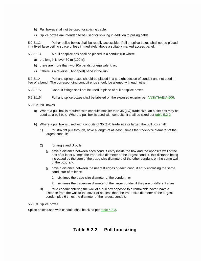
b) Pull boxes shall not be used for splicing cable.
c) Splice boxes are intended to be used for splicing in addition to pulling cable.
5.2.3.1.2 Pull or splice boxes shall be readily accessible. Pull or splice boxes shall not be placed in a fixed false ceiling space unless immediately above a suitably marked access panel.
5.2.3.1.3 A pull or splice box shall be placed in a conduit run where
a) the length is over 30 m (100 ft);
b) there are more than two 90o bends, or equivalent; or,
c) if there is a reverse (U-shaped) bend in the run.
5.2.3.1.4 Pull and splice boxes should be placed in a straight section of conduit and not used in lieu of a bend. The corresponding conduit ends should be aligned with each other.
5.2.3.1.5 Conduit fittings shall not be used in place of pull or splice boxes.
5.2.3.1.6 Pull and splice boxes shall be labeled on the exposed exterior per ANSI/TIA/EIA-606.
5.2.3.2 Pull boxes
a) Where a pull box is required with conduits smaller than 35 (1¼) trade size, an outlet box may be used as a pull box. Where a pull box is used with conduits, it shall be sized per table 5.2-2.
b) Where a pull box is used with conduits of 35 (1¼) trade size or larger, the pull box shall:
1) for straight pull through, have a length of at least 8 times the trade-size diameter of the largest conduit;
2) for angle and U pulls:
a have a distance between each conduit entry inside the box and the opposite wall of the box of at least 6 times the trade-size diameter of the largest conduit, this distance being increased by the sum of the trade-size diameters of the other conduits on the same wall of the box; and
b have a distance between the nearest edges of each conduit entry enclosing the same conductor of at least:
1 six times the trade-size diameter of the conduit; or
2 six times the trade-size diameter of the larger conduit if they are of different sizes.
3) for a conduit entering the wall of a pull box opposite to a removable cover, have a distance from the wall to the cover of not less than the trade-size diameter of the largest conduit plus 6 times the diameter of the largest conduit.
5.2.3.3 Splice boxes
Splice boxes used with conduit, shall be sized per table 5.2-3.
Table 5.2-2 Pull box sizing
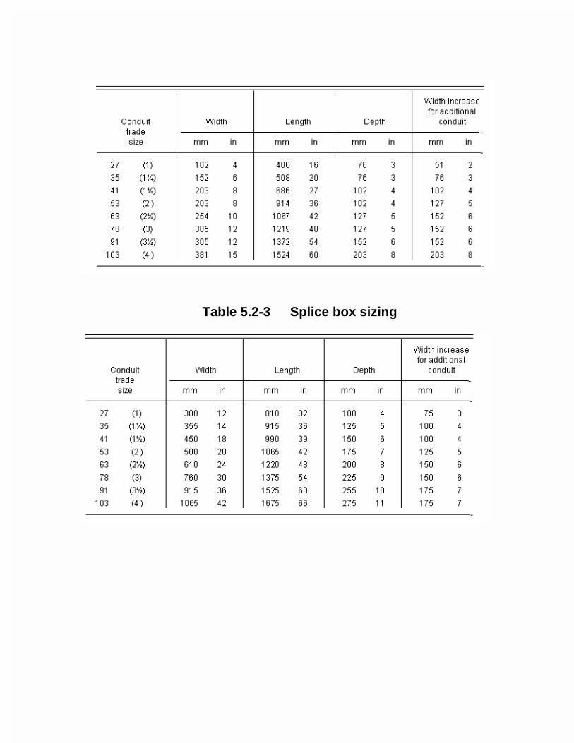
Table 5.2-3 Splice box sizing
ANSI/TIA/EIA-569-A6 Work area
6.1 General
Work areas are those spaces in a building where occupants interact with their telecommunications devices. It is important that the work area be properly designed for both occupants and devices. This Standard covers only those aspects of the work area relating to the telecommunications pathway and outlet.
6.2 Telecommunications outlet locations
6.2.1 General
A telecommunications outlet (box or connector) is the location of the connection point between the horizontal cables and cables connecting devices in the work area. A typical example in a building wall is a 100 mm x 100 mm (4 in x 4 in) telecommunications outlet box having the horizontal cables terminated via connectors on a faceplate, into which telecommunications devices in the work area are connected. Another example is the telecommunications outlet/connector mounted in a furniture system. Connected devices are typically items such as telephones, personal computers, and graphic or video terminals, each of which may require access to the horizontal distribution cabling via the telecommunications outlet/connector.
6.2.2 Outlet density
A minimum of one location for a telecommunications outlet/connector shall be installed per work area. For planning purposes, space allocated per work area averages 10 m2 (100 ft2). For building areas where it is difficult to add telecommunications boxes/connectors at a later date (e.g., private office space), a minimum of two separate outlet locations should be provided in the initial design for that area; they shall be located to offer maximum flexibility for change within the work area, e.g., on opposing walls in private office space.
6.2.3 Outlet location considerations
Telecommunications outlet locations should be coordinated with the furniture layout. A power outlet should be installed near each telecommunications outlet box (e.g., within 1 m (3 ft)). Telecommunications outlet locations are typically at the same height as the power outlet.
6.3 Furniture pathways and spaces
6.3.1 General
This section provides guidance to product and application designers about furniture telecommunications pathways.
6.3.1.1 Application planning
6.3.1.1.1 Interior design, telecommunications distribution planning, and power system distribution planning should be coordinated to avoid conflicting assignments for pathway or telecommunications
outlet/connector locations, installation sequencing problems, and other difficulties.
6.3.1.1.2 Untried distribution or termination strategies should be tested on actual furniture to ensure that pathway capacity, bend radius and telecommunications outlet/connector space are satisfactory.
6.3.2 Building interfaces
Furniture pathways are entered from building walls, columns, ceilings, or floors. The interface between buildings and furniture requires careful planning and may require special products or furniture options. Safety, reliability, and aesthetic concerns all favor concealment of the building-pathway to furniture-pathway interface. These pathway interfaces shall not trap access covers or otherwise block access to building junction boxes or pathways. Pathways used to interconnect the furniture with building horizontal pathways shall be provided with a cross-sectional area at least equal to the horizontal pathways cross-sectional area for the floor area being served. See section 4 for horizontal design requirements of pathways..
6.3.2.1 Walls and columns
Raceway should be provided between furniture pathways and the inside of building walls or columns.
6.3.2.2 Floors
A raceway should be provided between furniture pathways and horizontal floor pathway terminations (end of conduit, flush junction boxes, recessed junctions boxes, etc.). Alignment of furniture with building module, duct locations and other cable delivery means should be considered as part of the layout planning. Furniture shall not be arranged such that pathway interfaces are in aisle spaces, where people walk or place their feet, or other places where such obstructions could create a hazard.
6.3.2.3 Ceilings
Furniture pathways that are served from the ceiling shall meet the requirements of section 4.
6.3.3 Furniture Pathways
6.3.3.1 Application planning
Furniture manufacturers typically provide clients with information and assistance in planning to assure that adequate pathway capacity is available for the intended application. The following information is generally needed to be shared among manufacturer, customer/designer, and installer:
a) The number, type, and location of cable connections required in each work area;
b) The diameter and minimum bend radius of each cable type;
c) The strategy for connecting building pathways to furniture pathways, including the number, placement, and cross-sectional area of the required interfaces;
d) Furniture pathway cross sections and cable capacities;
e) The number of work areas in each furniture cluster.
6.3.3.2 Pathway fill factor
Required pathway capacity may be estimated from known cable requirements by taking total cable cross section to be approximately 20%-40% of the pathway cross section. As indicated by the large range of possible fill ratio, an estimate obtained in this way is only a rough guide and does not account for corners, oval cables, and some other factors. Actual cable mockups are the preferred method to determine pathway cable capacity.
NOTE - Pathway fill is under study.
6.3.3.3 Furniture pathway capacity
6.3.3.3.1 Furniture used for telecommunications cabling shall provide a minimum (straight) pathway cross-sectional area of 9.5 cm2 (1.50 in2). This cross-sectional area is for typical cable dimensions and a pathway fill of 33%. In general, furniture pathways at any elevation above the floor may need to be fed from either the floor or ceiling. Therefore, vertical pathways should be provided with a cross-sectional area at least equal to the horizontal pathway cross-sectional area. This specification is based on a work area cluster serving four persons with three connections each (for example, one UTP, one STP, and one optical fiber cable).
6.3.3.3.2 Because of complex raceway shapes and obstructions, cable installation in furniture pathways by fish-and-pull techniques may result in reduced capacity compared to laying cable into pathways. Fish-and-pull installation should not be used except when required by furniture pathway characteristics.
6.3.3.4 Access
Furniture should be arranged to ensure that access to telecommunications pathways is not blocked. For example, wall and panel systems may be chosen with a lay-in cable pathway at the top to make access convenient.
6.3.3.5 Furniture pathway bend radius
6.3.3.5.1 The conduit bend radius rule (see clause 4.4.2.3) shall apply to any inaccessible furniture pathway corner where pulling forces are expected to be used to install cable.
6.3.3.5.2 Cable can be installed in most furniture pathways by laying it in rather than by fishing and pulling, so the sweeping bends used in conduits are not required. The
minimum size pathway shall not force the cable into a bend radius less than 25 mm (1 in) under condition of maximum fill and the bend radius should be larger for certain types of cable.
6.3.3.5.3 Hybrid cables may require a larger bend radii than traditional cables. Hybrid cables are usually designed so that they may be unsheathed into component cables at the entry point to furniture, if necessary, to make the bend radius manageable. The designer should contact the cable manufacturer for minimum bending radii.
6.3.3.5.4 Reducing pathway capacity at corners
The effective cross section of furniture pathways at corners may be reduced by cable bend radius requirements. Because of the complex shapes and obstructions found in furniture pathways, it is not possible to give a general rule. Furniture manufacturers shall publish information on their products allowing users to determine effective pathway cross-section reduction for representative cables.
6.3.3.6 Power/telecommunications separation
6.3.3.6.1 Furniture pathways often run parallel to power raceways; floor and ceiling interfaces are often divided into power and telecommunications. In such cases, separation shall be provided to meet the requirements of clause 10.3. 6.3.3.6.2 In multichannel metallic pathways, dividers between channels shall be bonded to ground.
6.3.4 Furniture spaces
6.3.4.1 General
This section covers furniture that can support horizontal cabling by housing things like slack cable
storage, multi-user telecommunications outlet assemblies, and consolidation points.
6.3.4.1.1 Safety requirements
Furniture and cabling shall comply with applicable local and federal building and safety codes.
6.3.4.1.2 Security and access
Furniture designed or used to house multi-user telecommunications outlet assemblies or consolidation points should provide for appropriate security (for example, key locking, tool-removable covers, or other suitable means) and service access and should be located at a convenient working height, to facilitate installation, moves, adds and changes. Multi-user telecommunications outlet assemblies and consolidation points shall not be installed in furniture unless that unit of furniture is permanently secured to the building structure.
6.3.4.1.3 Internal spaces
Furniture intended to house multi-user telecommunications outlet assemblies or consolidation points shall provide space for strain relieving, terminating, and storing slack for the horizontal cables for the planned number of connections.
6.3.4.2 Furniture types
The following sections describe common furniture types and are not intended to be exhaustive or to preclude future innovation.
6.3.4.2.1 Cabinets
Cabinets, including overhead storage, can be designed to provide a concealed interface between walls, columns, and furniture pathways. Such interface cabinets may provide removable surfaces (secured from inside) in the fashion of the equipment racks used in laboratories and factories.
6.3.4.2.2 Furniture partitions
Some furniture partitions, in addition to internal pathways, may have accessible interior spaces suitable for slack cable storage, multi-user telecommunications outlet assemblies, or consolidation points.
6.3.4.2.3 Utility columns
In addition to the typical utility column in figure 4.6-1, a utility column may resemble a structural column, or a cabinet or panel extended to the suspended ceiling.
6.3.5 Furniture telecommunications outlet/connector
6.3.5.1 Location and mounting
6.3.5.1.1 Cabling system performance is sensitive to the arrangement of slack cable behind the telecommunications outlet/connector. Sufficient space shall be provided so that bend radius requirements are not violated in termination. The location, mounting, or strain relief of the telecommunications outlet/connector should allow pathway covers and trim to be removed without disturbing the cable termination. This may be done by appropriate furniture design, by use of external mounting enclosures, or in other ways.
6.3.5.1.2 It is suggested that telecommunications outlets/connectors be mounted in such a way that they do not reduce the required pathway cabling capacity.
NOTE - The federal Americans with Disabilities Act (ADA) may affect mounting locations in some instances.
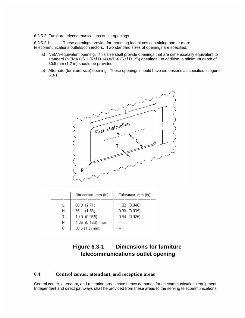
6.3.5.2 Furniture telecommunications outlet openings
6.3.5.2.1 These openings provide for mounting faceplates containing one or more telecommunications outlets/connectors. Two standard sizes of openings are specified:
a) NEMA-equivalent opening. This size shall provide openings that are dimensionally equivalent to standard (NEMA OS 1 (Ref D.14),WD-6 (Ref D.15)) openings. In addition, a minimum depth of 30.5 mm (1.2 in) should be provided.
b) Alternate (furniture-size) opening. These openings should have dimensions as specified in figure 6.3-1.
Figure 6.3-1 Dimensions for furniture telecommunications outlet opening
6.4 Control center, attendant, and reception areas
Control center, attendant, and reception areas have heavy demands for telecommunications equipment. Independent and direct pathways shall be provided from these areas to the serving telecommunications

closet or equipment room. Where conduit protrudes through the floor, it shall be terminated in a box or per clause 4.4.2. Where built-in, flush-mounted, or recessed installations are planned, they shall be designed with access to the pathway.
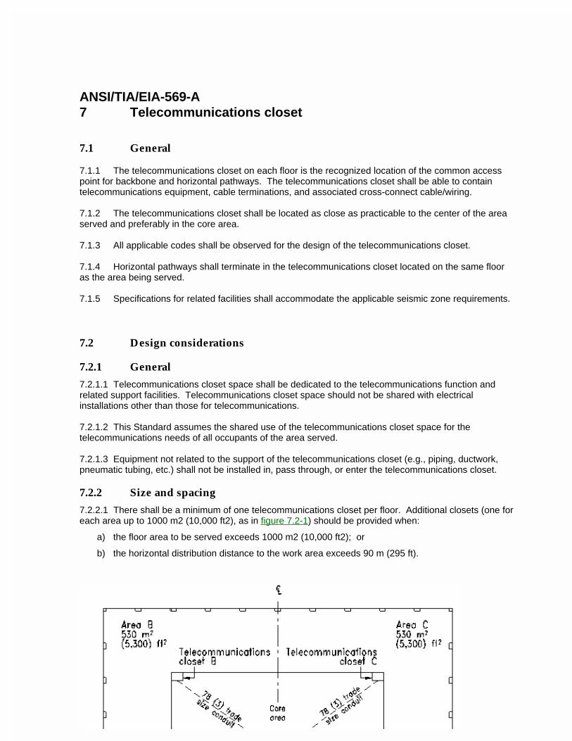
ANSI/TIA/EIA-569-A7 Telecommunications closet
7.1 General
7.1.1 The telecommunications closet on each floor is the recognized location of the common access point for backbone and horizontal pathways. The telecommunications closet shall be able to contain telecommunications equipment, cable terminations, and associated cross-connect cable/wiring.
7.1.2 The telecommunications closet shall be located as close as practicable to the center of the area served and preferably in the core area.
7.1.3 All applicable codes shall be observed for the design of the telecommunications closet.
7.1.4 Horizontal pathways shall terminate in the telecommunications closet located on the same floor as the area being served.
7.1.5 Specifications for related facilities shall accommodate the applicable seismic zone requirements.
7.2 Design considerations
7.2.1 General
7.2.1.1 Telecommunications closet space shall be dedicated to the telecommunications function and related support facilities. Telecommunications closet space should not be shared with electrical installations other than those for telecommunications.
7.2.1.2 This Standard assumes the shared use of the telecommunications closet space for the telecommunications needs of all occupants of the area served.
7.2.1.3 Equipment not related to the support of the telecommunications closet (e.g., piping, ductwork, pneumatic tubing, etc.) shall not be installed in, pass through, or enter the telecommunications closet.
7.2.2 Size and spacing
7.2.2.1 There shall be a minimum of one telecommunications closet per floor. Additional closets (one for each area up to 1000 m2 (10,000 ft2), as in figure 7.2-1) should be provided when:
a) the floor area to be served exceeds 1000 m2 (10,000 ft2); or
b) the horizontal distribution distance to the work area exceeds 90 m (295 ft).
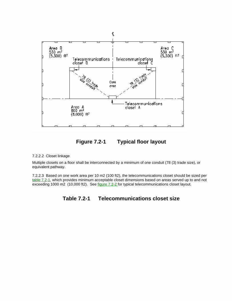
Figure 7.2-1 Typical floor layout
7.2.2.2 Closet linkage
Multiple closets on a floor shall be interconnected by a minimum of one conduit (78 (3) trade size), or equivalent pathway.
7.2.2.3 Based on one work area per 10 m2 (100 ft2), the telecommunications closet should be sized per table 7.2-1, which provides minimum acceptable closet dimensions based on areas served up to and not exceeding 1000 m2 (10,000 ft2). See figure 7.2-2 for typical telecommunications closet layout.
Table 7.2-1 Telecommunications closet size
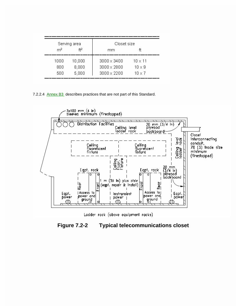
7.2.2.4 Annex B3 describes practices that are not part of this Standard.
Figure 7.2-2 Typical telecommunications closet
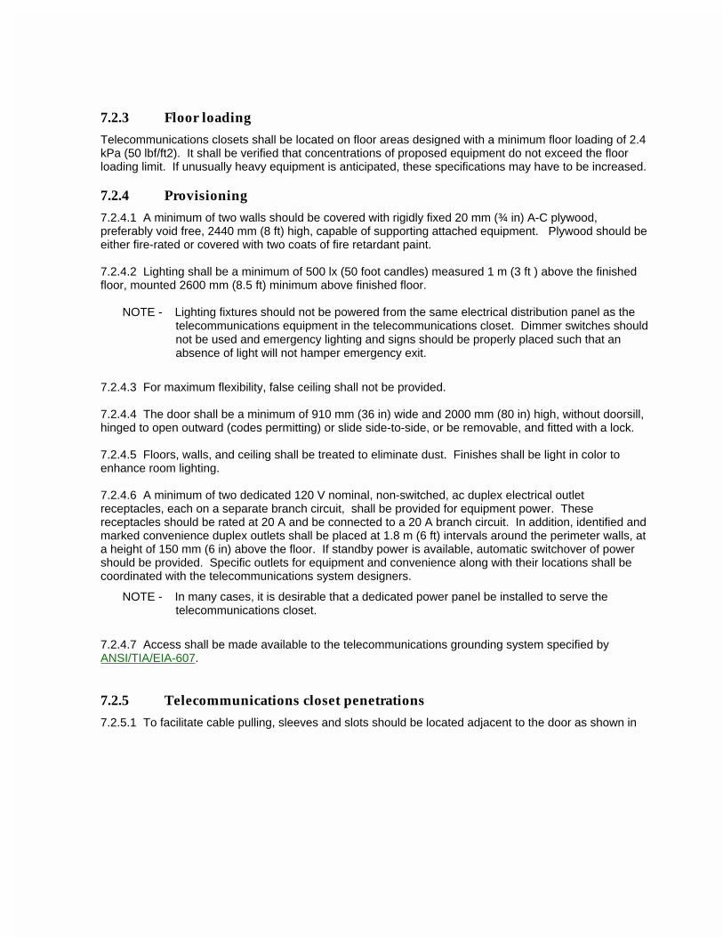
7.2.3 Floor loading
Telecommunications closets shall be located on floor areas designed with a minimum floor loading of 2.4 kPa (50 lbf/ft2). It shall be verified that concentrations of proposed equipment do not exceed the floor loading limit. If unusually heavy equipment is anticipated, these specifications may have to be increased.
7.2.4 Provisioning
7.2.4.1 A minimum of two walls should be covered with rigidly fixed 20 mm (¾ in) A-C plywood, preferably void free, 2440 mm (8 ft) high, capable of supporting attached equipment. Plywood should be either fire-rated or covered with two coats of fire retardant paint.
7.2.4.2 Lighting shall be a minimum of 500 lx (50 foot candles) measured 1 m (3 ft ) above the finished floor, mounted 2600 mm (8.5 ft) minimum above finished floor.
NOTE - Lighting fixtures should not be powered from the same electrical distribution panel as the telecommunications equipment in the telecommunications closet. Dimmer switches should not be used and emergency lighting and signs should be properly placed such that an absence of light will not hamper emergency exit.
7.2.4.3 For maximum flexibility, false ceiling shall not be provided.
7.2.4.4 The door shall be a minimum of 910 mm (36 in) wide and 2000 mm (80 in) high, without doorsill, hinged to open outward (codes permitting) or slide side-to-side, or be removable, and fitted with a lock.
7.2.4.5 Floors, walls, and ceiling shall be treated to eliminate dust. Finishes shall be light in color to enhance room lighting.
7.2.4.6 A minimum of two dedicated 120 V nominal, non-switched, ac duplex electrical outlet receptacles, each on a separate branch circuit, shall be provided for equipment power. These receptacles should be rated at 20 A and be connected to a 20 A branch circuit. In addition, identified and marked convenience duplex outlets shall be placed at 1.8 m (6 ft) intervals around the perimeter walls, at a height of 150 mm (6 in) above the floor. If standby power is available, automatic switchover of power should be provided. Specific outlets for equipment and convenience along with their locations shall be coordinated with the telecommunications system designers.
NOTE - In many cases, it is desirable that a dedicated power panel be installed to serve the telecommunications closet.
7.2.4.7 Access shall be made available to the telecommunications grounding system specified by ANSI/TIA/EIA-607.
7.2.5 Telecommunications closet penetrations
7.2.5.1 To facilitate cable pulling, sleeves and slots should be located adjacent to the door as shown in
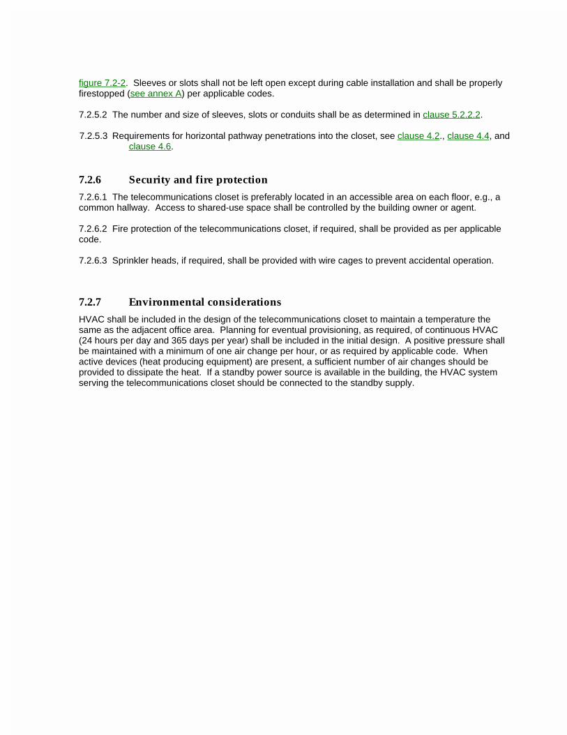
figure 7.2-2. Sleeves or slots shall not be left open except during cable installation and shall be properly firestopped (see annex A) per applicable codes.
7.2.5.2 The number and size of sleeves, slots or conduits shall be as determined in clause 5.2.2.2.
7.2.5.3 Requirements for horizontal pathway penetrations into the closet, see clause 4.2., clause 4.4, and clause 4.6.
7.2.6 Security and fire protection
7.2.6.1 The telecommunications closet is preferably located in an accessible area on each floor, e.g., a common hallway. Access to shared-use space shall be controlled by the building owner or agent.
7.2.6.2 Fire protection of the telecommunications closet, if required, shall be provided as per applicable code.
7.2.6.3 Sprinkler heads, if required, shall be provided with wire cages to prevent accidental operation.
7.2.7 Environmental considerations
HVAC shall be included in the design of the telecommunications closet to maintain a temperature the same as the adjacent office area. Planning for eventual provisioning, as required, of continuous HVAC (24 hours per day and 365 days per year) shall be included in the initial design. A positive pressure shall be maintained with a minimum of one air change per hour, or as required by applicable code. When active devices (heat producing equipment) are present, a sufficient number of air changes should be provided to dissipate the heat. If a standby power source is available in the building, the HVAC system serving the telecommunications closet should be connected to the standby supply.
ANSI/TIA/EIA-569-A8 Equipment room
8.1 General
8.1.1 The equipment room is a centralized space for telecommunications equipment (e.g., PBX, computing equipment, video switch) that serves specific occupants of the building). Any or all of the functions of a telecommunications closet or entrance facility may alternately be provided by an equipment room.
8.1.2 This section describes those parameters required to render the equipment space or area usable for initial and future equipment installations.
8.1.3 The room shall house only equipment directly related to the telecommunications system and its environmental support systems.
8.1.4 Specifications for related facilities shall accommodate the applicable seismic zone requirements.
8.2 Design considerations
8.2.1 Site selection
8.2.1.1 When selecting the equipment room site, avoid locations that are restricted by building components that limit expansion such as elevators, core, outside walls, or other fixed building walls. Accessibility for the delivery of large equipment to the equipment room should be provided (see annex B4). Access to shared-use space shall be controlled by the building owner or agent. It is desirable to locate the equipment room close to the backbone pathway.
8.2.1.2 Floor loading
Floor loading capacity in the equipment room shall be sufficient to bear both the distributed and concentrated load of the installed equipment. The equipment room shall be designed for a minimum distributed load rating of at 4.8 kPa (100 lbf/ft2) and a minimum concentrated load rating of at least 8.8 kN (2,000 lbf). If unusually heavy equipment is anticipated, these specifications may have to be increased.
8.2.1.3 Water infiltration
The equipment room shall not be located below water level unless preventive measures against water infiltration are employed. The room shall be free of water or drain pipes not directly required in support of the equipment within the room. A floor drain shall be provided within the room if risk of water ingress exists.
8.2.1.4 HVAC
The equipment room shall be located with ready access to the main HVAC delivery system.
8.2.1.5 Electromagnetic interference
The room shall be located away from sources of electromagnetic interference. Special attention shall be given to electrical power supply transformers, motors and generators, x-ray equipment, radio or radar transmitters, and induction sealing devices.
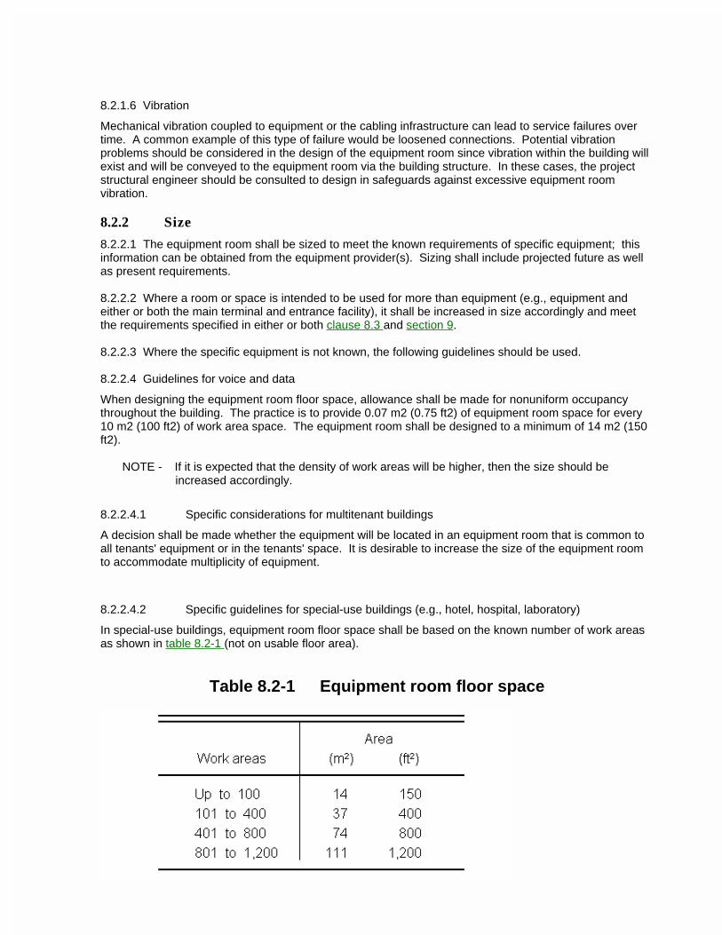
8.2.1.6 Vibration
Mechanical vibration coupled to equipment or the cabling infrastructure can lead to service failures over time. A common example of this type of failure would be loosened connections. Potential vibration problems should be considered in the design of the equipment room since vibration within the building will exist and will be conveyed to the equipment room via the building structure. In these cases, the project structural engineer should be consulted to design in safeguards against excessive equipment room vibration.
8.2.2 Size
8.2.2.1 The equipment room shall be sized to meet the known requirements of specific equipment; this information can be obtained from the equipment provider(s). Sizing shall include projected future as well as present requirements.
8.2.2.2 Where a room or space is intended to be used for more than equipment (e.g., equipment and either or both the main terminal and entrance facility), it shall be increased in size accordingly and meet the requirements specified in either or both clause 8.3 and section 9.
8.2.2.3 Where the specific equipment is not known, the following guidelines should be used.
8.2.2.4 Guidelines for voice and data
When designing the equipment room floor space, allowance shall be made for nonuniform occupancy throughout the building. The practice is to provide 0.07 m2 (0.75 ft2) of equipment room space for every 10 m2 (100 ft2) of work area space. The equipment room shall be designed to a minimum of 14 m2 (150 ft2).
NOTE - If it is expected that the density of work areas will be higher, then the size should be increased accordingly.
8.2.2.4.1 Specific considerations for multitenant buildings
A decision shall be made whether the equipment will be located in an equipment room that is common to all tenants' equipment or in the tenants' space. It is desirable to increase the size of the equipment room to accommodate multiplicity of equipment.
8.2.2.4.2 Specific guidelines for special-use buildings (e.g., hotel, hospital, laboratory)
In special-use buildings, equipment room floor space shall be based on the known number of work areas as shown in table 8.2-1 (not on usable floor area).
Table 8.2-1 Equipment room floor space
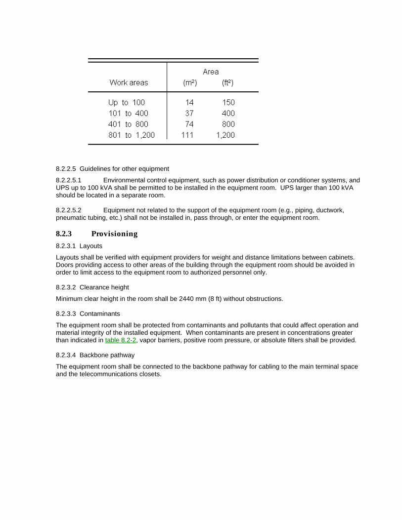
8.2.2.5 Guidelines for other equipment
8.2.2.5.1 Environmental control equipment, such as power distribution or conditioner systems, and UPS up to 100 kVA shall be permitted to be installed in the equipment room. UPS larger than 100 kVA should be located in a separate room.
8.2.2.5.2 Equipment not related to the support of the equipment room (e.g., piping, ductwork, pneumatic tubing, etc.) shall not be installed in, pass through, or enter the equipment room.
8.2.3 Provisioning
8.2.3.1 Layouts
Layouts shall be verified with equipment providers for weight and distance limitations between cabinets. Doors providing access to other areas of the building through the equipment room should be avoided in order to limit access to the equipment room to authorized personnel only.
8.2.3.2 Clearance height
Minimum clear height in the room shall be 2440 mm (8 ft) without obstructions.
8.2.3.3 Contaminants
The equipment room shall be protected from contaminants and pollutants that could affect operation and material integrity of the installed equipment. When contaminants are present in concentrations greater than indicated in table 8.2-2, vapor barriers, positive room pressure, or absolute filters shall be provided.
8.2.3.4 Backbone pathway
The equipment room shall be connected to the backbone pathway for cabling to the main terminal space and the telecommunications closets.
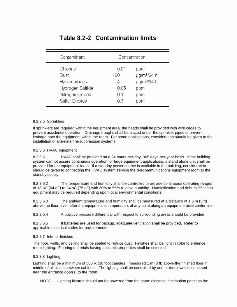
8.2.3.5 Sprinklers
If sprinklers are required within the equipment area, the heads shall be provided with wire cages to prevent accidental operation. Drainage troughs shall be placed under the sprinkler pipes to prevent leakage onto the equipment within the room. For some applications, consideration should be given to the installation of alternate fire-suppression systems.
8.2.3.6 HVAC equipment
8.2.3.6.1 HVAC shall be provided on a 24 hours-per-day, 365 days-per-year basis. If the building system cannot assure continuous operation for large equipment applications, a stand alone unit shall be provided for the equipment room. If a standby power source is available in the building, consideration should be given to connecting the HVAC system serving the telecommunications equipment room to the standby supply.
8.2.3.6.2 The temperature and humidity shall be controlled to provide continuous operating ranges of 18 oC (64 oF) to 24 oC (75 oF) with 30% to 55% relative humidity. Humidification and dehumidification equipment may be required depending upon local environmental conditions.
8.2.3.6.3 The ambient temperature and humidity shall be measured at a distance of 1.5 m (5 ft) above the floor level, after the equipment is in operation, at any point along an equipment aisle center line.
8.2.3.6.4 A positive pressure differential with respect to surrounding areas should be provided.
8.2.3.6.5 If batteries are used for backup, adequate ventilation shall be provided. Refer to applicable electrical codes for requirements.
8.2.3.7 Interior finishes
The floor, walls, and ceiling shall be sealed to reduce dust. Finishes shall be light in color to enhance room lighting. Flooring materials having antistatic properties shall be selected.
8.2.3.8 Lighting
Lighting shall be a minimum of 500 lx (50 foot candles), measured 1 m (3 ft) above the finished floor in middle of all aisles between cabinets. The lighting shall be controlled by one or more switches located near the entrance door(s) to the room.
NOTE - Lighting fixtures should not be powered from the same electrical distribution panel as the
telecommunications equipment in the equipment room. Dimmer switches should not be used and emergency lighting and signs should be properly placed such that an absence of light will not hamper emergency exit.
8.2.3.9 Power
8.2.3.9.1 A separate supply circuit serving the equipment room shall be provided and terminated in its own electrical panel. Electric power provisioning for the equipment room is not specified herein because it is dependent upon the equipment load and supporting facilities.
8.2.3.9.2 If a standby power source is available in the building, the equipment room panel should be connected to the standby supply.
8.2.3.10Door
The door shall be a minimum of 910 mm (36 in) wide and 2000 mm (80 in) high, without doorsill, and shall be fitted with a lock. If it is anticipated that large equipment will be delivered to the equipment room, a double door (1820 mm (72 in) wide by 2280 mm (90 in) high) without doorsill and center post is recommended.
8.2.3.11Equipment grounding
Access shall be made available to the telecommunications grounding system specified by ANSI/TIA/EIA-607.
8.2.3.12Auxiliary fire extinguishers
Portable fire extinguishers shall be provided and maintained within the equipment room per applicable code.
8.2.3.13Acoustical noise
Noisy equipment should be located outside the equipment room.
8.3 Main terminal space
8.3.1 General
8.3.1.1 The main terminal space is a centralized space that houses the main cross-connect and may combine features of an entrance facility and equipment room. It is commonly used as a separate space in multitenant buildings to serve all tenants. This space shall be located and provisioned to support the two-level backbone topology specified in ANSI/TIA/EIA-568-A.
8.3.1.2 This section describes those parameters required to render the main terminal space usable for initial and future cable installations.
8.3.1.3 The space shall house only facilities directly related to the telecommunications system and its environmental support systems.
8.3.1.4 Where a space is intended to be used for more than the main distribution frame/terminal (e.g., equipment and either or both the terminal and entrance facility), it shall be increased in size accordingly and, additionally, meet the requirements specified in clauses 8.1 and 8.2, and section 9.
8.3.2 Design consideration
8.3.2.1 Site selection
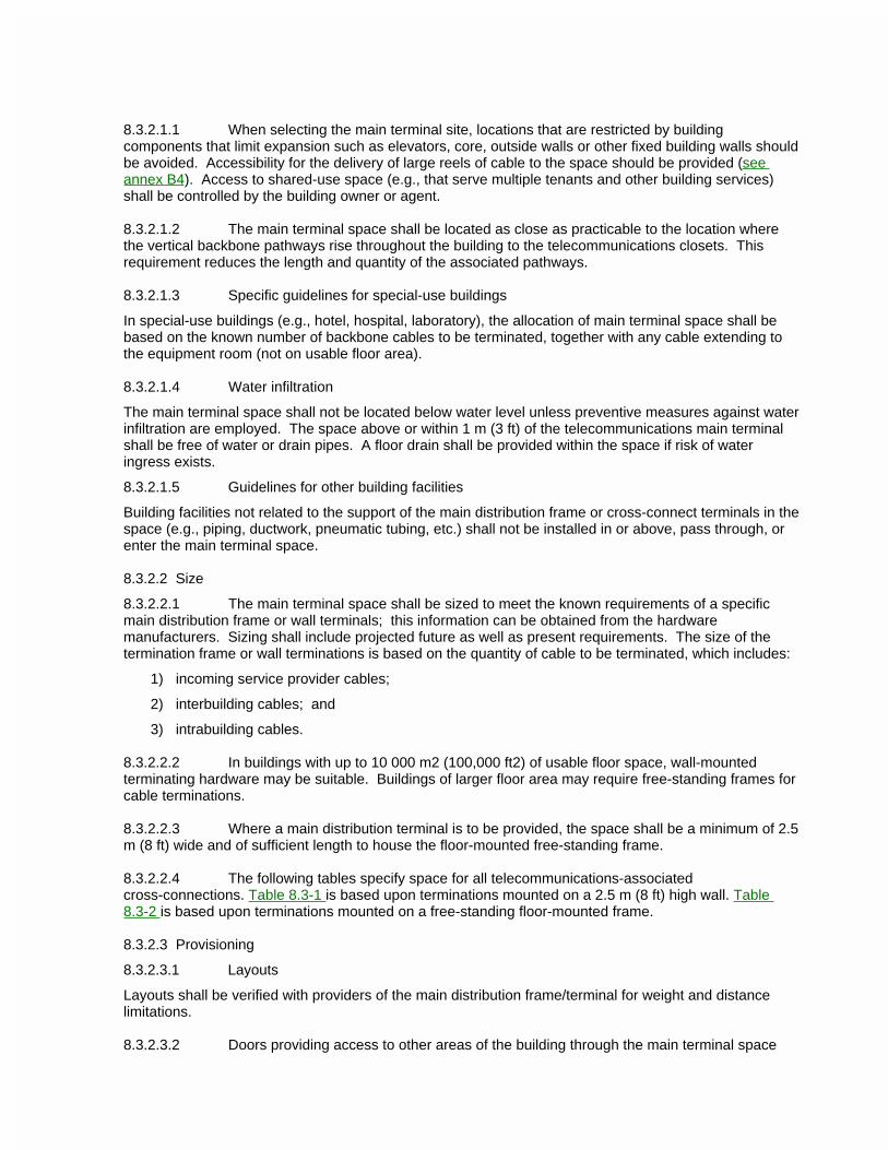
8.3.2.1.1 When selecting the main terminal site, locations that are restricted by building components that limit expansion such as elevators, core, outside walls or other fixed building walls should be avoided. Accessibility for the delivery of large reels of cable to the space should be provided (see annex B4). Access to shared-use space (e.g., that serve multiple tenants and other building services) shall be controlled by the building owner or agent.
8.3.2.1.2 The main terminal space shall be located as close as practicable to the location where the vertical backbone pathways rise throughout the building to the telecommunications closets. This requirement reduces the length and quantity of the associated pathways.
8.3.2.1.3 Specific guidelines for special-use buildings
In special-use buildings (e.g., hotel, hospital, laboratory), the allocation of main terminal space shall be based on the known number of backbone cables to be terminated, together with any cable extending to the equipment room (not on usable floor area).
8.3.2.1.4 Water infiltration
The main terminal space shall not be located below water level unless preventive measures against water infiltration are employed. The space above or within 1 m (3 ft) of the telecommunications main terminal shall be free of water or drain pipes. A floor drain shall be provided within the space if risk of water ingress exists.
8.3.2.1.5 Guidelines for other building facilities
Building facilities not related to the support of the main distribution frame or cross-connect terminals in the space (e.g., piping, ductwork, pneumatic tubing, etc.) shall not be installed in or above, pass through, or enter the main terminal space.
8.3.2.2 Size
8.3.2.2.1 The main terminal space shall be sized to meet the known requirements of a specific main distribution frame or wall terminals; this information can be obtained from the hardware manufacturers. Sizing shall include projected future as well as present requirements. The size of the termination frame or wall terminations is based on the quantity of cable to be terminated, which includes:
1) incoming service provider cables;
2) interbuilding cables; and
3) intrabuilding cables.
8.3.2.2.2 In buildings with up to 10 000 m2 (100,000 ft2) of usable floor space, wall-mounted terminating hardware may be suitable. Buildings of larger floor area may require free-standing frames for cable terminations.
8.3.2.2.3 Where a main distribution terminal is to be provided, the space shall be a minimum of 2.5 m (8 ft) wide and of sufficient length to house the floor-mounted free-standing frame.
8.3.2.2.4 The following tables specify space for all telecommunications-associated cross-connections. Table 8.3-1 is based upon terminations mounted on a 2.5 m (8 ft) high wall. Table 8.3-2 is based upon terminations mounted on a free-standing floor-mounted frame.
8.3.2.3 Provisioning
8.3.2.3.1 Layouts
Layouts shall be verified with providers of the main distribution frame/terminal for weight and distance limitations.
8.3.2.3.2 Doors providing access to other areas of the building through the main terminal space
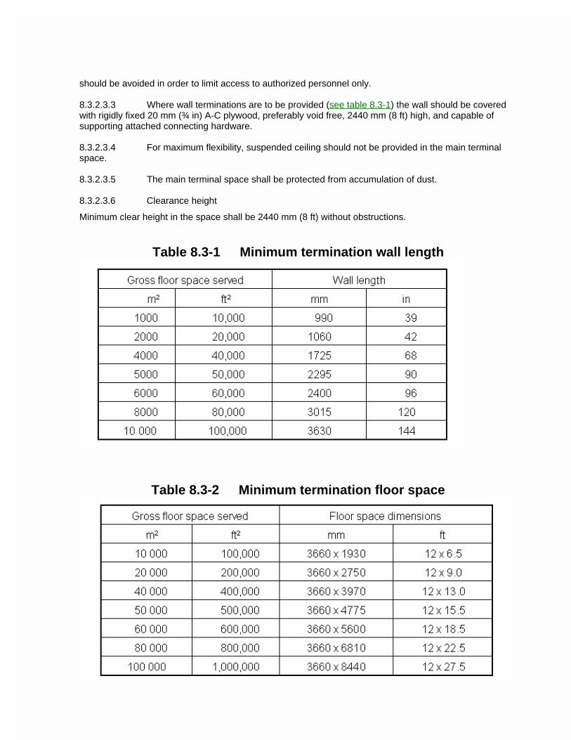
should be avoided in order to limit access to authorized personnel only.
8.3.2.3.3 Where wall terminations are to be provided (see table 8.3-1) the wall should be covered with rigidly fixed 20 mm (¾ in) A-C plywood, preferably void free, 2440 mm (8 ft) high, and capable of supporting attached connecting hardware.
8.3.2.3.4 For maximum flexibility, suspended ceiling should not be provided in the main terminal space.
8.3.2.3.5 The main terminal space shall be protected from accumulation of dust.
8.3.2.3.6 Clearance height
Minimum clear height in the space shall be 2440 mm (8 ft) without obstructions.
Table 8.3-1 Minimum termination wall length
Table 8.3-2 Minimum termination floor space
8.3.2.3.7 Backbone pathways
8.3.2.3.7.1 The main terminal space shall be connected to the backbone pathway system throughout the building and campus.
8.3.2.3.7.2 The size of pathways between the entrance space and the main terminal space shall be the same as the entrance pathways unless the route is through open accessible areas. In such cases, the pathway placed may be only for those cables initially installed with supporting structure adequate to accommodate future pathway requirements.
8.3.2.3.7.3 Either or both the quantity of conduits and size of pathways between the main terminal space, the telecommunications closets, and the equipment room should be based on the long-term quantity of cable required. In some cases, the pathway placed may be only for those cables initially installed with supporting structure adequate to accommodate future pathway requirements.
8.3.2.3.8 Sprinklers
If sprinklers are required within the main terminal space, the heads shall be provided with wire cages to prevent accidental operation. Drainage troughs shall be placed under the sprinkler pipes to prevent leakage onto the terminals/equipment within the space. Consideration should be given to installation of a dry pipe or pre-action system.
8.3.2.3.9 Lighting
Lighting for the main terminal space shall be a minimum of 500 lx (50 foot candles), measured 1 m (3 ft) above the finished floor. The lighting should be controlled by one or more switches located near the space.
NOTE - Lighting fixtures should not be powered from the same electrical distribution panel as the telecommunications equipment in the main terminal space. Dimmer switches should not be used and emergency lighting and signs should be properly placed such that an absence of light will not hamper emergency exit.
8.3.2.3.10 Electrical Power
Convenience duplex receptacles shall be placed along the wall, spaced 1.8 m (6 ft) and at a height of 150 mm (6 in) above the floor.
8.3.2.3.11 Door
The door to the space shall be a minimum of 910 mm (36 in) wide and 2000 mm (80 in) high, without doorsill, and shall be fitted with a lock. If it is anticipated that large cable reels will be delivered to the main terminal space, a double door (1820 mm (72 in) wide by 2280 mm (90 in) high) without doorsill and center post is recommended.
8.3.2.3.12 Equipment grounding
Access shall be made available to the telecommunications grounding system as specified by ANSI/TIA/EIA-607.
ANSI/TIA/EIA-569-A9 Entrance facilities
9.1 General
9.1.1 The entrance facility consists of the telecommunications service entrance to the building, including the entrance through the building wall, and continuing to the entrance room or space. The entrance facility may contain the backbone pathways that link to the main terminal space and to other buildings in campus situations. Antenna entrances may also constitute part of the entrance facility. See annex C for interbuilding backbone pathways and related spaces requirements.
9.1.2 Specifications for related facilities shall accommodate the applicable seismic zone requirements.
9.2 Entrance location considerations
9.2.1 All carriers and telecommunications providers involved in providing service to the building shall be contacted to establish their requirements and explore alternatives for delivering service. The location of other utilities, such as electrical, water, gas, and sewer, shall be considered in the selection of the telecommunications entrance facility location.
9.2.2 An alternate entrance facility should be provided where security, continuity of service, or other special needs exist.
9.2.3 When locating antenna fields, line-of-sight interference and signal interference should be avoided.
9.2.4 Equipment not related to the support of the entrance facility (e.g., piping, ductwork, pneumatic tubing, etc.) should not be installed in, pass through, or enter the telecommunications entrance facility.
9.3 Service entrance pathway
9.3.1 General
9.3.1.1 A service entrance pathway shall be provided. The basic methods for provisioning are underground, buried, aerial pathways, and tunnels.
9.3.1.2 In determining the total number of pathways required, the planner shall consider
a) type and use of building;
b) growth;
c) difficulty of adding pathways in the future;
d) alternate entrance;
e) type and size of cables likely to be installed.
9.3.2 Entrance pathway methods
Listed here are brief descriptions of typical entrance pathway methods. Refer to annex C for more detailed information.
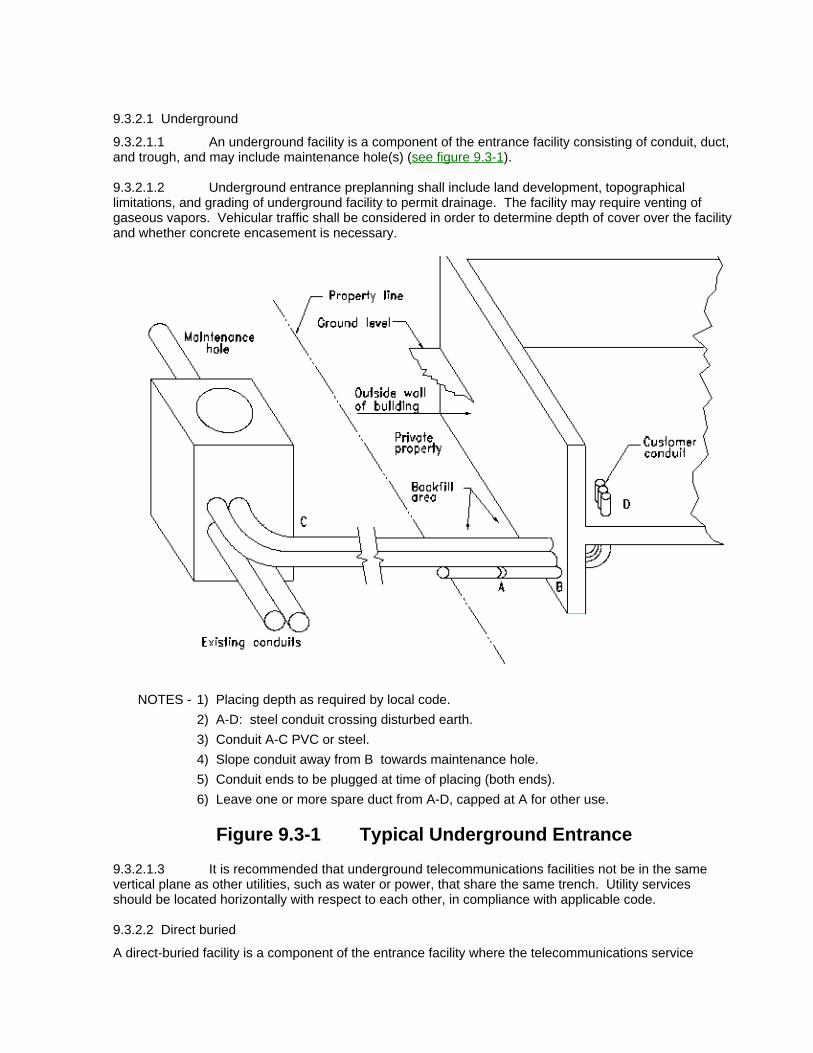
9.3.2.1 Underground
9.3.2.1.1 An underground facility is a component of the entrance facility consisting of conduit, duct, and trough, and may include maintenance hole(s) (see figure 9.3-1).
9.3.2.1.2 Underground entrance preplanning shall include land development, topographical limitations, and grading of underground facility to permit drainage. The facility may require venting of gaseous vapors. Vehicular traffic shall be considered in order to determine depth of cover over the facility and whether concrete encasement is necessary.
NOTES - 1) Placing depth as required by local code.
2) A-D: steel conduit crossing disturbed earth.
3) Conduit A-C PVC or steel.
4) Slope conduit away from B towards maintenance hole.
5) Conduit ends to be plugged at time of placing (both ends).
6) Leave one or more spare duct from A-D, capped at A for other use.
Figure 9.3-1 Typical Underground Entrance
9.3.2.1.3 It is recommended that underground telecommunications facilities not be in the same vertical plane as other utilities, such as water or power, that share the same trench. Utility services should be located horizontally with respect to each other, in compliance with applicable code.
9.3.2.2 Direct buried
A direct-buried facility is a component of the entrance facility where the telecommunications service
cables are completely encased in the earth. Direct burial is achieved by trenching, augering or boring, or plowing. Plowing is not covered in this Standard. The designer should consider that although direct buried may be more economical initially, the cable facilities cannot be reinforced or replaced easily.
9.3.2.3 Aerial
An aerial facility is a component of the entrance facility consisting of poles, cable-support strand, and support system. When contemplating the use of aerial facilities, consider:
a) aesthetics of the building and surrounding location;
b) storm loading;
c) applicable codes;
d) clearances and separation for electrical and road;
e) mechanical protection;
f) span lengths;
g) building attachments;
h) future cable plant reinforcement;
i) number of cables involved.
9.3.2.4 Tunnels
The service entrance to a buildings in a campus environment may be via a utility tunnel.
9.4 Entrance point
9.4.1 General
An entrance point is a component of the entrance facility, which is the point of emergence of telecommunications cabling through an exterior wall, through a concrete floor slab, or from the end of an entrance conduit.
9.4.2 Conduit entrance design guidelines
9.4.2.1 Conduit entrances consist of several 103 (4) trade size conduits and, optionally, several 53 (2) trade size conduits. In general, 53 (2) trade size conduits should be
considered for use with small diameter (e.g., 13 mm (0.5 in)) cables such as optical fiber and CATV cable, while 103 (4) trade size conduit should be considered for use with larger diameter, multipair copper cables. Innerduct may also be placed within 103 (4) trade size conduit to facilitate smaller diameter cables such as optical fiber and coaxial cable.
9.4.2.2 As a minimum, two 103 (4) trade size, with at least one spare 103 (4) trade size, conduits should be considered for each entrance point. In addition three 53 (2) trade size conduits should be considered.
9.4.2.3 Penetration and termination
The conduit shall extend into undisturbed earth and a minimum of 600 mm (24 in) beyond the exterior of the foundation. When terminated at the inside of the building wall, the conduit shall be reamed and bushed. When terminated at the inside of the building wall, the conduit shall have a smooth bell-shaped finish unless it extends to a remote entrance room, space, or area (see figures 9.4-1 and 9.4-2). The conduit or sleeve shall be securely fastened to the building.

NOTE - Some nonmetallic innerduct commonly used for underground or outside plant construction may not have the appropriate fire safety characteristics for use as a pathway within the building.
9.4.2.4 Drainage
The conduit shall slope downwards towards the exterior (see figure 9.4-2). Where water infiltration is anticipated, an exterior drainage box shall be installed at the entrance point.
9.4.2.5 Gas, water, and vermin
All conduits shall be plugged to restrict infiltration of gas, water, and vermin. To further ensure that gases do not enter the building, a venting system may need to be installed external to the building.
9.4.2.6 Pull box
9.4.2.6.1 A pull box shall be installed inside the building at the entrance point for cable pulling and splicing when
a) the building conduit is extended from the entrance conduit; or
b) warranted by excessive conduit length; or
c) the quantity of bends exceeds the equivalent of two 90o bends.
9.4.2.6.2 Pull boxes shall be provided in conduit backbone pathways based on the criteria described in clause 5.2.3. Pull box sizing shall be based on table 5.2-2.
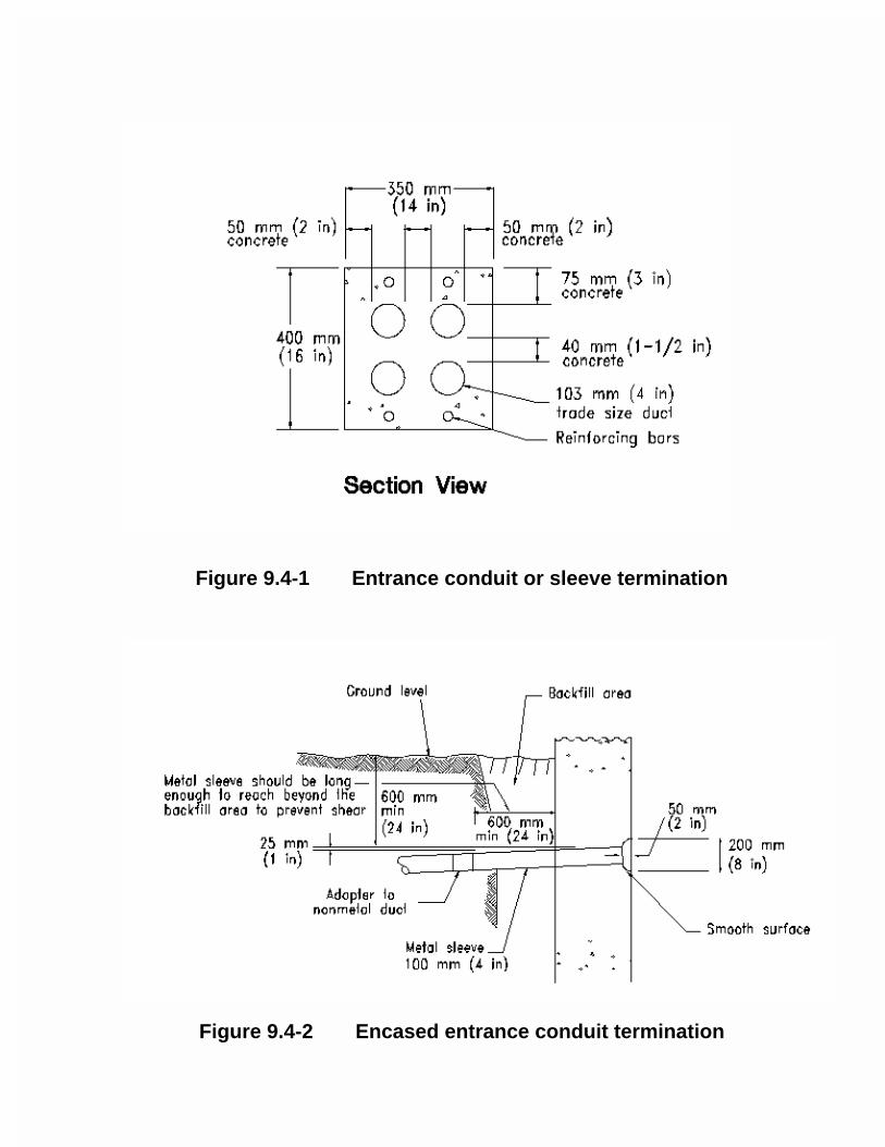
Figure 9.4-1 Entrance conduit or sleeve termination
Figure 9.4-2 Encased entrance conduit termination
9.5 Entrance room or space
9.5.1 General
9.5.1.1 The entrance room or space is the component of the entrance facility that provides space for the placing and termination of protectors on the entrance cable and may contain network interface devices. If network interface devices and telecommunications equipment are required in the entrance room, additional space will be needed. Where an entrance room or space is intended to be used for more than protectors (e.g., PBX equipment, main terminal, or both), it shall be increased in size accordingly and meet the requirements specified in section 8.
9.5.1.2 The size of pathways, between the entrance point and the entrance room or space, shall be the same as the entrance pathways unless the route is through open accessible areas. In such cases, the pathway placed may be only for those cables initially installed with supporting structure adequate to accommodate future pathway requirements.
9.5.1.3 Antenna field entrance rooms shall be designed per applicable code. The antenna pathway from the antenna field to the entrance room shall provide isolation for the antenna cables from other backbone cables. The antenna entrance room shall be located as close as practicable to the antenna field.
9.5.2 Location
The entrance room or space shall be located in a dry area not subject to flooding and should be as close as practicable to the building entrance point and next to the electrical service room in order to reduce the length of bonding conductor to the electrical grounding system. See ANSI/TIA/EIA-607.
9.5.3 Design
The decision whether a room or open area is provided shall be based on security, quantity, type of protectors, size of building, and physical location within the building. For buildings exceeding 2000 m2 (20,000 ft2) usable floor space, an enclosed room should be provided.
9.5.4 Size
The entrance room shall be sized to meet the known requirements of the specific protectors; this information can be obtained from the equipment provider(s). Sizing shall include projected future as well as present requirements.
9.5.5 Provisioning
9.5.5.1 A minimum of one wall should be covered with rigidly fixed 20 mm (¾ in) A-C plywood, preferably void free, 2440 mm (8 ft) high, capable of supporting the protectors. Plywood should be either fire-rated or covered with two coats of fire retardant paint.
9.5.5.2 Lighting shall be a minimum of 500 lx (50 foot candles) measured 1 m (3 ft) above the finished floor, mounted 2600 mm (8.5 ft) minimum above finished floor.
NOTE - Lighting fixtures should not be powered from the same electrical distribution panel as the telecommunications equipment in the entrance room or space. Dimmer switches should not be used and emergency lighting and signs should be properly placed such that an absence of light will not hamper emergency exit.
9.5.5.3 For maximum flexibility, false ceiling shall not be provided.

9.5.5.4 The access door shall be a minimum of 910 mm (36 in) wide and 2000 mm (80 in) high and shall be fitted with a lock.
9.5.5.5 Floors, walls, and ceiling shall be treated to eliminate dust. Finishes shall be light in color to enhance room lighting.
9.5.5.6 Electrical power
A minimum of two dedicated 120 V nominal, non-switch, ac duplex electrical outlet receptacles, each on a separate branch circuit, shall be provided for equipment power. These receptacles should be rated at 20 A and should be connected to 20 A branch circuit. 9.5.5.7 Access shall be made available to the telecommunications grounding system specified by ANSI/TIA/EIA-607.
AMSI/TIA/EIA-569-A10 Miscellaneous items
10.1 Firestopping
All telecommunications firestopping shall comply with applicable code (also see annex A).
10.2 Elevator telecommunications
A 21 (¾) trade size conduit shall be provided from the telecommunications closet to a suitable device box. This location shall apply to passenger, freight, and window-washing elevators and be coordinated with the elevator contractor.
10.3 Horizontal pathway separation from EMI sources
10.3.1 Separation between telecommunications and power cables
Coinstallation of telecommunications cable and power cable is governed by applicable electrical code for safety. For minimum separation requirements of telecommunications cable from typical branch circuits (120/240V, 20A), Article 800-52 of ANSI/NFPA 70 (Ref D.3) shall be applied, for example:
-- separation from power conductors;
-- separation and barriers within raceways; and
-- separation within outlet boxes or compartments.
10.3.2 Other related requirements
The following additional requirements shall also be met:
-- the building itself shall be suitably protected from lightning (seeANSI/NFPA 780 (Ref D.4));
-- surge protection shall be applied at the electrical service entrance (see Article 280 of ANSI/NFPA 70 and section 9.11 of ANSI/IEEE 1100 (Ref D.1));
-- ANSI/TIA/EIA-607 Commercial Building Grounding and Bonding Requirements for Telecommunications shall be followed; and
-- faulty electrical wiring shall be corrected (see section 7.5 of ANSI/IEEE 1100).
10.3.3 Reducing noise coupling
In order to further reduce noise coupling from sources such as electrical power wiring, radio frequency (RF) sources, large motors and generators, induction heaters, and arc welders, the following additional precautions should be considered:
-- Increased physical separation.
-- Electrical branch circuit line, neutral, and grounding conductors should be maintained close together (e.g., twisted, sheathed, taped, or bundled together) for minimizing inductive coupling into telecommunications cabling.
-- Use of surge protectors in branch circuits that can further limit the propagation of electrical surges. Follow guidelines in section 9.11.2 of ANSI/IEEE 1100.

-- Use of fully enclosed, grounded metallic raceway or grounded conduit or use of cable installed close to a grounded metallic surface that will also limit inductive noise coupling. Refer to clause 5.5.2.7 of ANSI/TIA/EIA-607 and section 9 of ANSI/IEEE 1100.
ANSI/TIA/EIA-569-AAnnex A (normative) Firestopping
This annex is normative and is part of this Standard.
The purpose of this annex is to provide guidelines and formalize requirements concerning the firestopping of commercial buildings. Because of the growing importance of passive fire protection, this subject has been changed (from an informative) to a normative part of this standard. It is imperative that, in addition to the material presented here, the reader consult their Authority Having Jurisdiction (AHJ) concerning local firestopping requirements. Readers are further encouraged to work directly with firestop manufacturers to provide appropriate drawings that support fire test documentation and other submittals to satisfy the specific requirements of the AHJ for the work being performed.
A.1 Scope
A.1.1 This annex provides guidance toward utilization of standardized specific design and construction practices as well as methods, materials and other considerations for re-establishing the integrity of fire-rated architectural structures and assemblies (e.g., walls, floors, ceilings) when these barriers are penetrated by components.
A.1.2 For additional information on how to firestop penetrations through fire-rated barriers refer to annex reference D.19. For firestop installation methods and other additional information, refer to the BICSI Telecommunications Distribution Methods Manual (Ref D.11).
A.2 Terminology and definitions
A.2.1 When referring to firestopping systems, the terms "qualified," "tested," "listed," "classified," and "approved" are essentially synonymous; each refers to firestopping systems that have been tested by an independent laboratory and evaluated as effective (different laboratories use different terms). For simplicity, this annex will use the term "qualified" to represent all of these terms. The terms "system" and "design" are also nearly synonymous; both refer to an arrangement of specific firestopping materials in a specific configuration. The term "system" is used in this context throughout this annex.
A.2.2 See section 3 of this Standard for definitions applicable to firestopping.
A.3 Firestops
A.3.1 Introduction
The function of a firestop is to prevent fire, smoke, or water from passing through a barrier penetration. This applies to building construction, renovation, or rehabilitation. In many cases, firestop seals are required to perform secondary functions, in acting as environmental protection seals as well as sealing around penetrations which may reach high temperatures or may move axially or laterally. These
requirements must be taken into consideration in the application of firestops.
A.3.2 Fire rated barriers
A.3.2.1 Commercial buildings are divided into fire zones by fire-rated barriers which are architectural structures or assemblies (e.g., walls, floors, and ceilings). The perimeters of the fire zones are established in accordance with the building codes and construction requirements. Building designers and constructors shall reference reports on barrier materials before choosing an appropriate floor or wall design (load bearing or non-load bearing) for a fire zone perimeter.
CAUTION - The failure of a barrier to perform according to design may have grave consequences if it allows heat, flame, smoke, or gases to pass.
A.3.2.2 Any disruption in the continuity or integrity of the surface of a fire-rated barrier nullifies the performance rating of the barrier. All penetrations shall be protected by approved firestops.
A.3.3 Penetrations
A.3.3.1 Penetrations are openings made in fire-rated barriers. There are two kinds of penetrations: "Membrane Penetrations" pierce or interrupt the outside surface of only one side of a fire-rated barrier. "Through Penetrations" completely transit a fire-rated barrier, piercing both outside surfaces of the barrier. Penetrations are made to install building elements (e.g., conduits, cables, piping, fixtures, boxes, ducts, etc.) and must be firestopped to return the barrier to its intended fire rating.
A.3.3.2 No additional firestopping is needed for electrical apparatus such as boxes, junction boxes, breaker panels and fixtures which have been tested and approved for use in fire-rated assemblies other than normal patching where the item penetrates a fire-rated assembly. Receptacles and switch boxes shall be firestopped on the back side of the units where jurisdiction mandates. Installation criteria shall be listed in the installation instructions in order for the AHJ to issue a certificate of occupancy.
A.3.4 Evaluation of firestop systems
A.3.4.1 Firestops are specific combinations of materials installed and (possibly) supported or anchored in a certain way. They are qualified by independent agencies, based on the materials performance when tested in a particular configuration.
A.3.4.2 It is not possible to test every arrangement of firestops. Many test assemblies are based on testing of worst case in a number of variables and must demonstrate an ability to perform despite the mass of thermal-conducting elements expected to penetrate openings (e.g., a heavily loaded cable tray containing PVC-jacketed cable bundles).
NOTE - The fact that a material is noncombustible does not qualify that material as a firestop unless it has passed performance testing as a through penetration firestop following ASTM E 814 (Ref D.10) or UL 1479 (Ref D.18) .
A.3.5 Qualification testing
A.3.5.1 Testing of firestop systems provides evidence of the system's performance across a range of variable conditions known or expected to exist in a sealing situation.
A.3.5.2 If metallic sleeves are to be used for the pathway for cables through a barrier (e.g., two-hour rated gypsum wallboard or three-hour rated poured concrete construction) there shall be verifiable test programs (ASTM E 814 or UL 1479) by using this pass-through method.
A.3.6 Testing requirements for through-penetration firestops
The fire resistivity of through-penetration firestops is evaluated under positive pressure, "time-versus-temperature" furnace conditions. This testing allows the resistivity to be assessed through controlled fire exposure. For fire resistivity testing guidelines and evaluation material, refer to standards: ASTM E 119 (Ref D.9), ASTM E 814, UL 1479.
A.3.7 Firestop ratings for through-penetration firestops
A.3.7.1 Two rating classifications for firestops are available under the rating criteria of ASTM E 814; they may be relevant in assessing the fire hazard of a particular application:
a) F (Hours) withstands the test fire for the rating period without
-- permitting flames to pass through the firestop;
-- flame to occur on any element of the unexposed side of the firestop (e.g., autoignition);
-- developing any opening in the firestop during the hose stream test that permits a projection of water beyond the unexposed side.
b) T (Hours) meets the criteria for an "F Rating" and limits temperature rise during the rating period. The temperature on any unexposed surface can increase no more than 181 oC (325 oF) plus ambient.
NOTE - An optional classification found in UL 1479 is an "L" rating which does not currently appear in ASTM E 814:
c) L ( Air Leakage) addresses the issue of leakage by reporting a number value:
-- A lower number equals a better "L" rating.
-- The temperatures of the exposed face of the test sample is to be 24 oC 11 oC (75 oF 20 oF) prior to the conduct of the test.
-- Total metered air flow is to be recorded at ambient temperature and repeated at a test chamber temperature of 204 oC 5 oC (400 oF 10 oF).
-- See UL 1479 for preconditioning of the test specimen and chamber requirements.
A.3.8 Guidelines for membrane-penetration firestops
There are no specific test standards for qualifying or rating membrane-penetration firestops although guidelines can be found in various building codes. The reader shall check with the AHJ for local membrane-penetration requirements. In most cases, the guidelines require additional buildup of the wall opposite the membrane penetration or the installation of firestop pads on the back side of the membrane penetrant (i.e., receptacle and switch boxes).
A.3.9 Seismic considerations
The firestopping specification shall accommodate the applicable seismic zone requirements.
A.3.10 Engineering judgments
The large number of combinations of construction elements found in the real world creates application conditions falling outside the envelope of tested systems. As these conditions cannot be ignored, there is usually no alternative but to rely on an engineering judgment. Such judgments must be based on sound practice to ensure that life safety issues are not compromised. These judgments
a) should only be obtained from qualified technical personnel of a manufacturer of the firestop materials;
b) should be based upon full knowledge of the elements of the construction to be protected and an understanding of the probable behavior of that construction under E 814 fire test conditions for
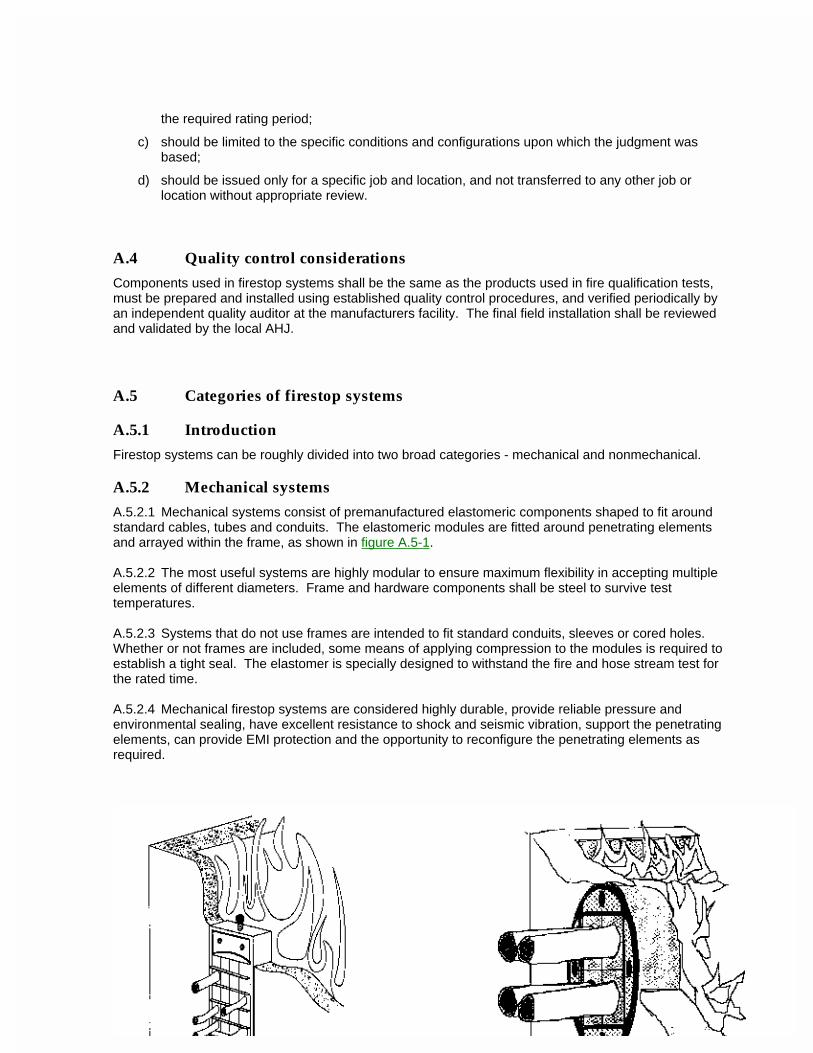
the required rating period;
c) should be limited to the specific conditions and configurations upon which the judgment was based;
d) should be issued only for a specific job and location, and not transferred to any other job or location without appropriate review.
A.4 Quality control considerations
Components used in firestop systems shall be the same as the products used in fire qualification tests, must be prepared and installed using established quality control procedures, and verified periodically by an independent quality auditor at the manufacturers facility. The final field installation shall be reviewed and validated by the local AHJ.
A.5 Categories of firestop systems
A.5.1 Introduction
Firestop systems can be roughly divided into two broad categories - mechanical and nonmechanical.
A.5.2 Mechanical systems
A.5.2.1 Mechanical systems consist of premanufactured elastomeric components shaped to fit around standard cables, tubes and conduits. The elastomeric modules are fitted around penetrating elements and arrayed within the frame, as shown in figure A.5-1.
A.5.2.2 The most useful systems are highly modular to ensure maximum flexibility in accepting multiple elements of different diameters. Frame and hardware components shall be steel to survive test temperatures.
A.5.2.3 Systems that do not use frames are intended to fit standard conduits, sleeves or cored holes. Whether or not frames are included, some means of applying compression to the modules is required to establish a tight seal. The elastomer is specially designed to withstand the fire and hose stream test for the rated time.
A.5.2.4 Mechanical firestop systems are considered highly durable, provide reliable pressure and environmental sealing, have excellent resistance to shock and seismic vibration, support the penetrating elements, can provide EMI protection and the opportunity to reconfigure the penetrating elements as required.
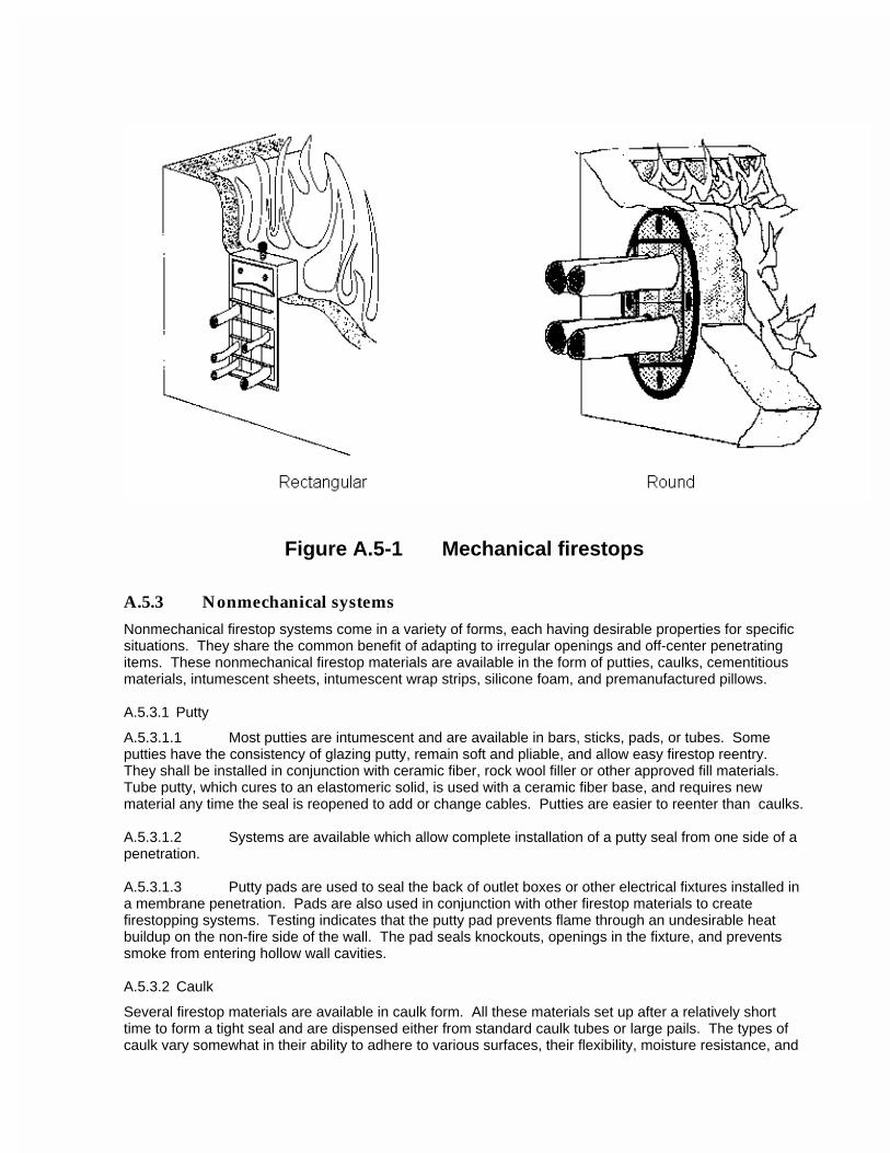
Figure A.5-1 Mechanical firestops
A.5.3 Nonmechanical systems
Nonmechanical firestop systems come in a variety of forms, each having desirable properties for specific situations. They share the common benefit of adapting to irregular openings and off-center penetrating items. These nonmechanical firestop materials are available in the form of putties, caulks, cementitious materials, intumescent sheets, intumescent wrap strips, silicone foam, and premanufactured pillows.
A.5.3.1 Putty
A.5.3.1.1 Most putties are intumescent and are available in bars, sticks, pads, or tubes. Some putties have the consistency of glazing putty, remain soft and pliable, and allow easy firestop reentry. They shall be installed in conjunction with ceramic fiber, rock wool filler or other approved fill materials. Tube putty, which cures to an elastomeric solid, is used with a ceramic fiber base, and requires new material any time the seal is reopened to add or change cables. Putties are easier to reenter than caulks.
A.5.3.1.2 Systems are available which allow complete installation of a putty seal from one side of a penetration.
A.5.3.1.3 Putty pads are used to seal the back of outlet boxes or other electrical fixtures installed in a membrane penetration. Pads are also used in conjunction with other firestop materials to create firestopping systems. Testing indicates that the putty pad prevents flame through an undesirable heat buildup on the non-fire side of the wall. The pad seals knockouts, openings in the fixture, and prevents smoke from entering hollow wall cavities.
A.5.3.2 Caulk
Several firestop materials are available in caulk form. All these materials set up after a relatively short time to form a tight seal and are dispensed either from standard caulk tubes or large pails. The types of caulk vary somewhat in their ability to adhere to various surfaces, their flexibility, moisture resistance, and
the quantity required for a rated firestop seal. Firestop caulks vary in composition, are water based, 100% solids, or solvent based, and typically are intumescent, endothermic and ablative. Some caulking materials can be installed from the underside of an opening without dripping or slumping.
CAUTION - Do not use solvent-based caulk seals which may give off toxic or noxious fumes in confined areas that are not well ventilated.
A.5.3.3 Cementitious (cement-like) materials
These materials are a dry powder premixed or mixed with water and more adaptable to large openings than putty or caulk. When using cementitious materials, it may be necessary to allow for thermal expansion or motion of the penetrating item. Plaster or ordinary grout shall not be used as a cementitious firestop. Seals made of grout or plaster may crack, fracture or fall out and be extremely difficult to repenetrate.
A.5.3.4 Intumescent sheets
Intumescent sheets with a sheet metal backing can be used to seal large openings or non-sheet metal sheets may be used with caulk or putty to fabricate a honeycomb-like partitioned opening for cable, conduit, metal or nonmetallic pipe. When using intumescent sheets, manufacturer's instructions shall be followed for anchoring and sealing.
A.5.3.5 Intumescent wrap strips
Intumescent wrap strips are usually used for firestopping plastic piping, insulated metal piping, cable, cable bundles, nonmetallic conduit, exposed innerduct, or any other material that may burn away in a fire and leave a significant void. Intumescent strips may also be used to increase fire endurance. Wrap or blankets are relatively soft and permit easy installation around penetrating elements.
A.5.3.6 Silicone foams
Early nonmechanical firestop systems were based on two-component silicone foams. Mixed in proper proportions at the right temperature, the two components expanded rapidly to form a cellular structure surrounding the penetrating items. This method is mainly used for large openings and the opening must be made structurally adequate and leak-tight to resist and control the expansive forces of the foam.
A.5.3.7 Premanufactured pillows
Premanufactured pillows are a recent development in firestop sealing. Unlike earlier pillows, which contained noncombustible fibers, contemporary pillows contain a specially treated, compressible fiber matrix. When exposed to fire, the matrix swells to provide further sealing, becomes rigid allowing the pillow seal to withstand the force of a hose stream as required by fire test standards. Pillows are often mistakenly regarded as temporary firestops because of their convenience. However, pillow fire-test qualification standards are the same as for any other sealing system.
NOTE - Some pillows must be restrained by a wire mesh or a metallic sheet for support.
A.6 Design consideration checklist
Use the following checklist to assist in meeting the requirements of the owner, the application, and the AHJ:
a) Type of installation
-- One side when access to the other side is impossible.
-- Installation from the bottom because of material characteristics which prevent the installation of the seal when the top of the opening is not accessible because of equipment location.
-- Floor, wall, or ceiling installation.
-- No additional firestopping is needed for electrical apparatus such as boxes, junction boxes, breaker panels, and fixtures which have been tested and approved for use in fire-rated assemblies other than normal patching where the item penetrates a fire-rated assembly. Receptacles and switch boxes shall be firestopped on the back side of the units where jurisdiction mandates. Installation criteria shall be listed in the installation instructions in order for the AHJ to issue a certificate of occupancy.
b) Barrier penetration:
-- round, square;
-- concrete block, solid concrete, brick, gypsum wall board etc.;
-- does it have penetrating items installed and what are they?
c) The opening:
-- diameter, or length and width;
-- depth;
-- access (single side or both sides);
-- room location;
-- penetrating items (approximate percent filled);
-- special features - steel sleeve or insulation.
d) Firestop requirements:
-- environmental;
-- cable management;
-- pressure barrier;
-- cold smoke or gas seal;
-- special requirements (such as an EMI barrier).
e) Penetrating items:
-- cables (by size and quantity);
-- pipes (by type and quantity);
-- cable tray or no cable tray;
-- any other unique penetrating items;
-- insulation on any penetrating item.
f) Code requirements:
-- governmental;
-- State;
-- local.

g) Test specifications:
-- ASTM;
-- UL (etc.);
-- military;
-- What are the test parameters?
ANSI/TIA/EIA-569-AAnnex B (informative)Additional section information
This annex is informative only and is not part of this Standard.
B.1 General
B.1.1 The latest edition of ANSI/NFPA 70 National Electric Code (NEC) covers safety aspects of electrical equipment and communications circuits (see Article 800 of Chapter 8). Per Section 90-3, Chapter 8 of the NEC is independent of the other chapters except where they are specifically referenced therein. In the NEC, electrical (power) equipment includes the service equipment: raceways, wireways, exposed wiring racks; feeder and branch circuits, receptacles and other outlets; panels, enclosures; and the grounding and bonding of systems, circuits and metallic objects likely to become energized. NEC Article 645 covers information technology equipment. ANSI/NFPA 75 Protection of Electronic Computer/Data Processing Equipment provides additional information based on NEC Article 645. NEC Section 300-22(c) covers wiring of communications circuits in plenums and air-handling spaces. An NRTL (Nationally Recognized Testing Laboratory), such as UL or CSA, covers the product safety aspects of telecommunications equipment and systems connected to the network. This reference list identifies several commonly referenced code articles but is not inclusive. Care should be exercised in referencing all applicable codes.
B.1.2 The latest edition of ANSI/NFPA 70 National Electrical Code (NEC) covers hazardous locations.
B.1.3 Conduit dimensions
Internal dimensions for various electrical conduits are provided in table B.1-1.
B.2 Horizontal pathways
B.2.1 Access floor (see clause 4.3)
B.2.1.1 Performance criteria
B.2.1.1.1 Dynamic loads
Dynamic or rolling loads on the casters are defined by frequency, size, and hardness of the wheel, and the combined weight of the cart and its contents. Rolling loads are the most important criteria because they have a more damaging effect on the access floor panel than static loads (see table B.2-1).
Table B.1-1 Conduit dimensions
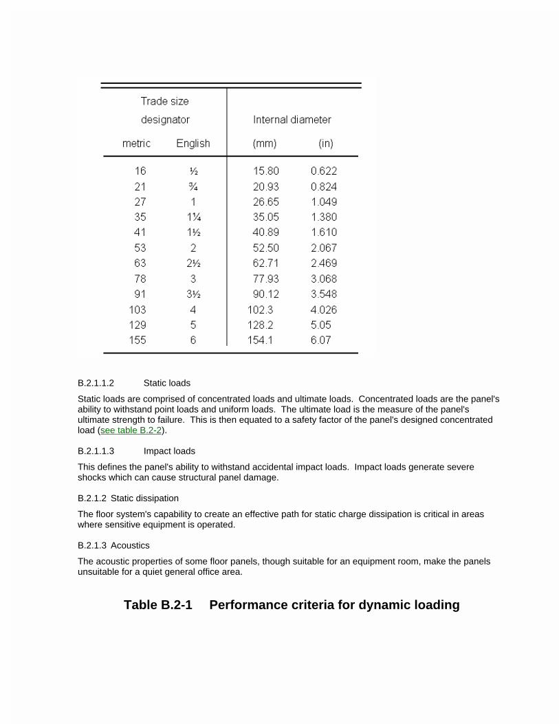
B.2.1.1.2 Static loads
Static loads are comprised of concentrated loads and ultimate loads. Concentrated loads are the panel's ability to withstand point loads and uniform loads. The ultimate load is the measure of the panel's ultimate strength to failure. This is then equated to a safety factor of the panel's designed concentrated load (see table B.2-2).
B.2.1.1.3 Impact loads
This defines the panel's ability to withstand accidental impact loads. Impact loads generate severe shocks which can cause structural panel damage.
B.2.1.2 Static dissipation
The floor system's capability to create an effective path for static charge dissipation is critical in areas where sensitive equipment is operated.
B.2.1.3 Acoustics
The acoustic properties of some floor panels, though suitable for an equipment room, make the panels unsuitable for a quiet general office area.
Table B.2-1 Performance criteria for dynamic loading
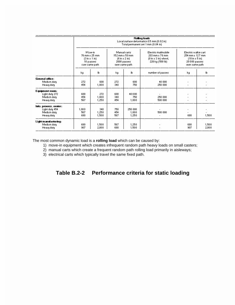
The most common dynamic load is a rolling load which can be caused by:1) move-in equipment which creates infrequent random path heavy loads on small casters;2) manual carts which create a frequent random path rolling load primarily in aisleways;3) electrical carts which typically travel the same fixed path.
Table B.2-2 Performance criteria for static loading
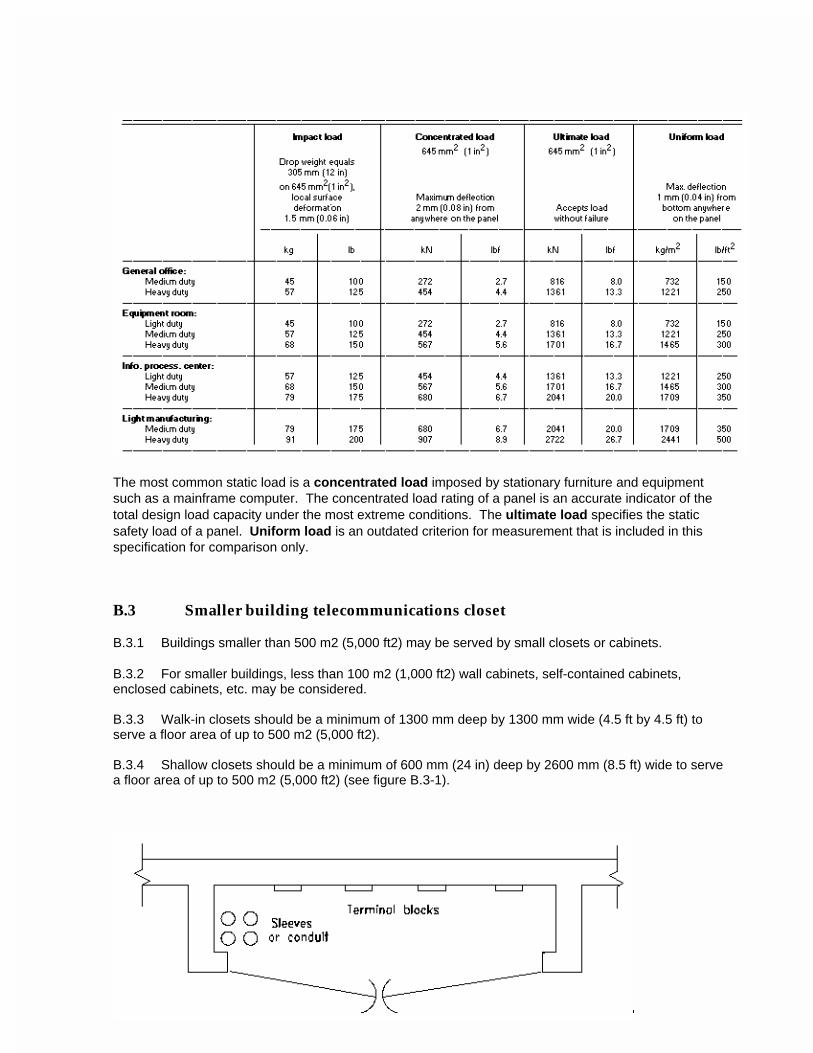
The most common static load is a concentrated load imposed by stationary furniture and equipment such as a mainframe computer. The concentrated load rating of a panel is an accurate indicator of the total design load capacity under the most extreme conditions. The ultimate load specifies the static safety load of a panel. Uniform load is an outdated criterion for measurement that is included in this specification for comparison only.
B.3 Smaller building telecommunications closet
B.3.1 Buildings smaller than 500 m2 (5,000 ft2) may be served by small closets or cabinets.
B.3.2 For smaller buildings, less than 100 m2 (1,000 ft2) wall cabinets, self-contained cabinets, enclosed cabinets, etc. may be considered.
B.3.3 Walk-in closets should be a minimum of 1300 mm deep by 1300 mm wide (4.5 ft by 4.5 ft) to serve a floor area of up to 500 m2 (5,000 ft2).
B.3.4 Shallow closets should be a minimum of 600 mm (24 in) deep by 2600 mm (8.5 ft) wide to serve a floor area of up to 500 m2 (5,000 ft2) (see figure B.3-1).
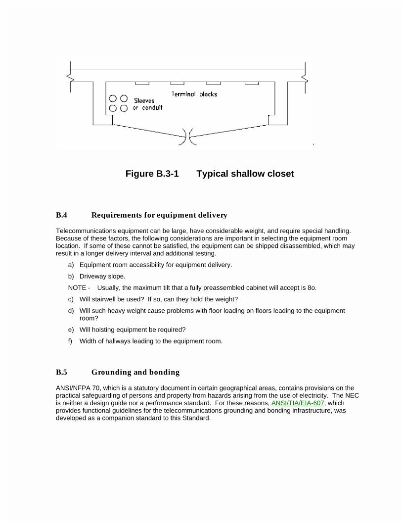
Figure B.3-1 Typical shallow closet
B.4 Requirements for equipment delivery
Telecommunications equipment can be large, have considerable weight, and require special handling. Because of these factors, the following considerations are important in selecting the equipment room location. If some of these cannot be satisfied, the equipment can be shipped disassembled, which may result in a longer delivery interval and additional testing.
a) Equipment room accessibility for equipment delivery.
b) Driveway slope.
NOTE - Usually, the maximum tilt that a fully preassembled cabinet will accept is 8o.
c) Will stairwell be used? If so, can they hold the weight?
d) Will such heavy weight cause problems with floor loading on floors leading to the equipment room?
e) Will hoisting equipment be required?
f) Width of hallways leading to the equipment room.
B.5 Grounding and bonding
ANSI/NFPA 70, which is a statutory document in certain geographical areas, contains provisions on the practical safeguarding of persons and property from hazards arising from the use of electricity. The NEC is neither a design guide nor a performance standard. For these reasons, ANSI/TIA/EIA-607, which provides functional guidelines for the telecommunications grounding and bonding infrastructure, was developed as a companion standard to this Standard.
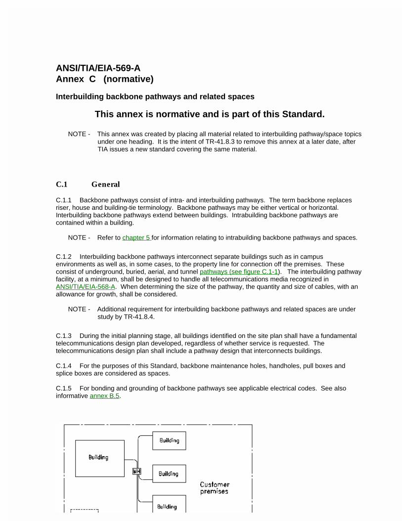
ANSI/TIA/EIA-569-AAnnex C (normative)
Interbuilding backbone pathways and related spaces
This annex is normative and is part of this Standard.
NOTE - This annex was created by placing all material related to interbuilding pathway/space topics under one heading. It is the intent of TR-41.8.3 to remove this annex at a later date, after TIA issues a new standard covering the same material.
C.1 General
C.1.1 Backbone pathways consist of intra- and interbuilding pathways. The term backbone replaces riser, house and building-tie terminology. Backbone pathways may be either vertical or horizontal. Interbuilding backbone pathways extend between buildings. Intrabuilding backbone pathways are contained within a building.
NOTE - Refer to chapter 5 for information relating to intrabuilding backbone pathways and spaces.
C.1.2 Interbuilding backbone pathways interconnect separate buildings such as in campus environments as well as, in some cases, to the property line for connection off the premises. These consist of underground, buried, aerial, and tunnel pathways (see figure C.1-1). The interbuilding pathway facility, at a minimum, shall be designed to handle all telecommunications media recognized in ANSI/TIA/EIA-568-A. When determining the size of the pathway, the quantity and size of cables, with an allowance for growth, shall be considered.
NOTE - Additional requirement for interbuilding backbone pathways and related spaces are under study by TR-41.8.4.
C.1.3 During the initial planning stage, all buildings identified on the site plan shall have a fundamental telecommunications design plan developed, regardless of whether service is requested. The telecommunications design plan shall include a pathway design that interconnects buildings.
C.1.4 For the purposes of this Standard, backbone maintenance holes, handholes, pull boxes and splice boxes are considered as spaces.
C.1.5 For bonding and grounding of backbone pathways see applicable electrical codes. See also informative annex B.5.
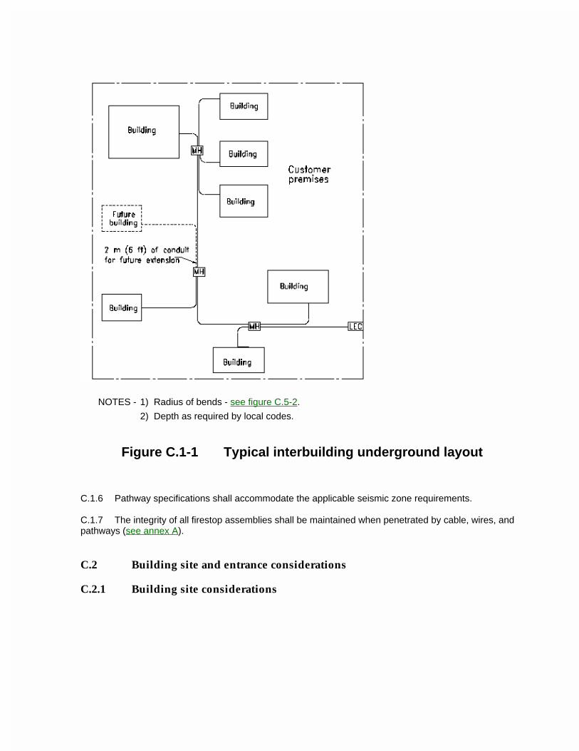
NOTES - 1) Radius of bends - see figure C.5-2.
2) Depth as required by local codes.
Figure C.1-1 Typical interbuilding underground layout
C.1.6 Pathway specifications shall accommodate the applicable seismic zone requirements.
C.1.7 The integrity of all firestop assemblies shall be maintained when penetrated by cable, wires, and pathways (see annex A).
C.2 Building site and entrance considerations
C.2.1 Building site considerations
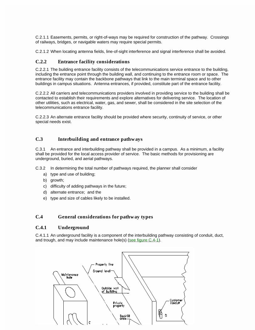
C.2.1.1 Easements, permits, or right-of-ways may be required for construction of the pathway. Crossings of railways, bridges, or navigable waters may require special permits.
C.2.1.2 When locating antenna fields, line-of-sight interference and signal interference shall be avoided.
C.2.2 Entrance facility considerations
C.2.2.1 The building entrance facility consists of the telecommunications service entrance to the building, including the entrance point through the building wall, and continuing to the entrance room or space. The entrance facility may contain the backbone pathways that link to the main terminal space and to other buildings in campus situations. Antenna entrances, if provided, constitute part of the entrance facility.
C.2.2.2 All carriers and telecommunications providers involved in providing service to the building shall be contacted to establish their requirements and explore alternatives for delivering service. The location of other utilities, such as electrical, water, gas, and sewer, shall be considered in the site selection of the telecommunications entrance facility.
C.2.2.3 An alternate entrance facility should be provided where security, continuity of service, or other special needs exist.
C.3 Interbuilding and entrance pathways
C.3.1 An entrance and interbuilding pathway shall be provided in a campus. As a minimum, a facility shall be provided for the local access provider of service. The basic methods for provisioning are underground, buried, and aerial pathways.
C.3.2 In determining the total number of pathways required, the planner shall consider
a) type and use of building;
b) growth;
c) difficulty of adding pathways in the future;
d) alternate entrance; and the
e) type and size of cables likely to be installed.
C.4 General considerations for pathway types
C.4.1 Underground
C.4.1.1 An underground facility is a component of the interbuilding pathway consisting of conduit, duct, and trough, and may include maintenance hole(s) (see figure C.4-1).
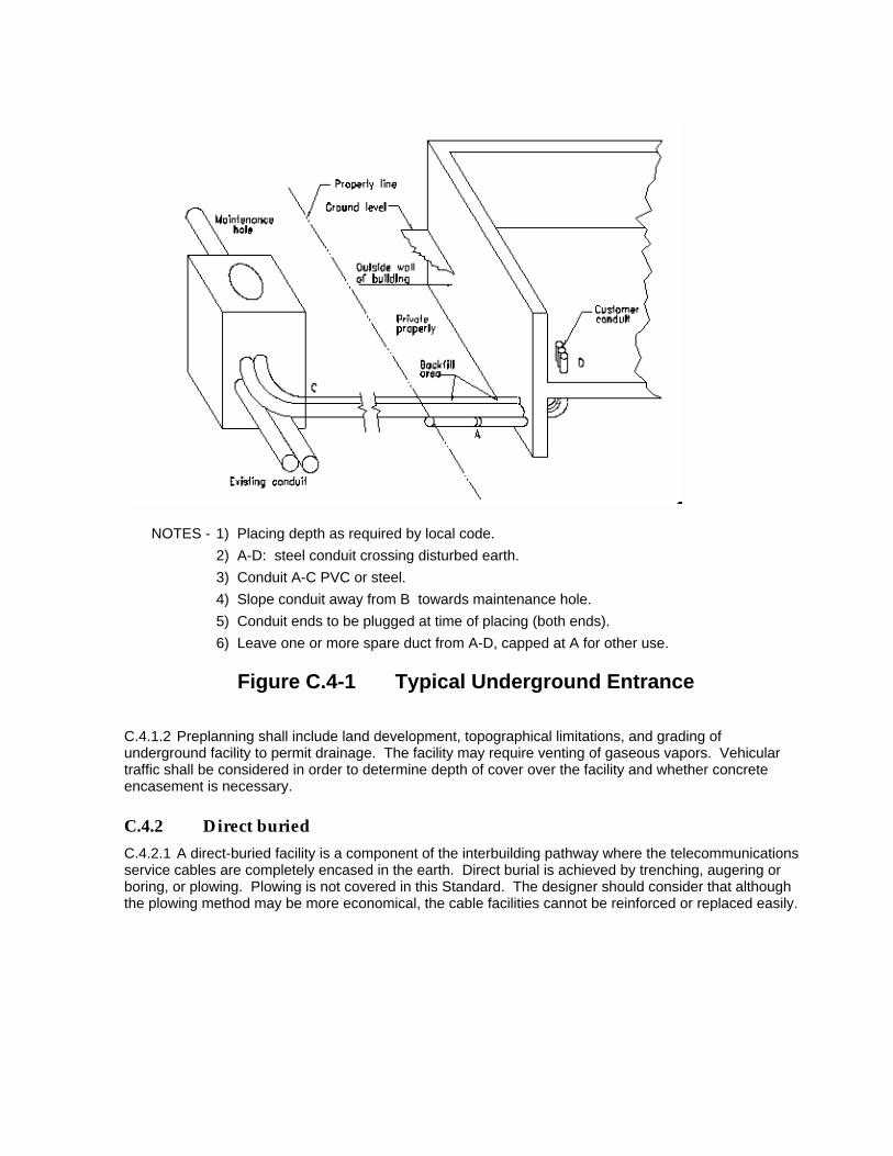
NOTES - 1) Placing depth as required by local code.
2) A-D: steel conduit crossing disturbed earth.
3) Conduit A-C PVC or steel.
4) Slope conduit away from B towards maintenance hole.
5) Conduit ends to be plugged at time of placing (both ends).
6) Leave one or more spare duct from A-D, capped at A for other use.
Figure C.4-1 Typical Underground Entrance
C.4.1.2 Preplanning shall include land development, topographical limitations, and grading of underground facility to permit drainage. The facility may require venting of gaseous vapors. Vehicular traffic shall be considered in order to determine depth of cover over the facility and whether concrete encasement is necessary.
C.4.2 Direct buried
C.4.2.1 A direct-buried facility is a component of the interbuilding pathway where the telecommunications service cables are completely encased in the earth. Direct burial is achieved by trenching, augering or boring, or plowing. Plowing is not covered in this Standard. The designer should consider that although the plowing method may be more economical, the cable facilities cannot be reinforced or replaced easily.
C.4.2.2 Design
C.4.2.2.1 The route selected shall be coordinated with landscaping, fencing, trees, paved areas, and other services, and should follow a natural parallel line of sight such as property lines, sidewalks, and driveways. Because of possible fences and shrubbery, a distance of approximately 2 m (6 ft) shall be maintained from the property line.
C.4.2.2.2 The design and installation of other services in a joint-use trench shall be coordinated and shall meet applicable codes.
C.4.2.3 Trenching
When trenching for the installation of direct-buried cable, it may be desirable to place conduit or duct in the same trench for possible future use.
C.4.2.4 Augering or boring
Augering or boring (pipe pushing) shall be considered for short distances, typically less than 45 m (150 ft), where trenching and plowing are inappropriate. Directional boring should also be considered. These techniques are applicable in situations where obstructions are present such as trees, railroad track, roads, sidewalks, and creeks.
C.4.3 AerialAn aerial facility is a component of the interbuilding pathway consisting of poles, cable-support strand, and support system. When contemplating the use of aerial facilities, consider the following list; figures C.4-2, C.4-3, C.4-4 and C.4-5 illustrate some of the suggested hardware devices for aerial cable installations:
a) aesthetics of the building and surrounding location;
b) storm loading;
c) applicable codes;
d) clearances and separation for electrical and road;
e) mechanical protection;
f) span lengths;
g) building attachments;
h) future cable plant reinforcement;
i) number of cables involved.
C.4.4 Tunnels
C.4.4.1 General
Telecommunications pathways may be installed in tunnels alone or jointly with other facilities. The pathways may consist of conduit, tray, wireway, or support strand. See figure C.4-6.
C.4.4.2 Planning
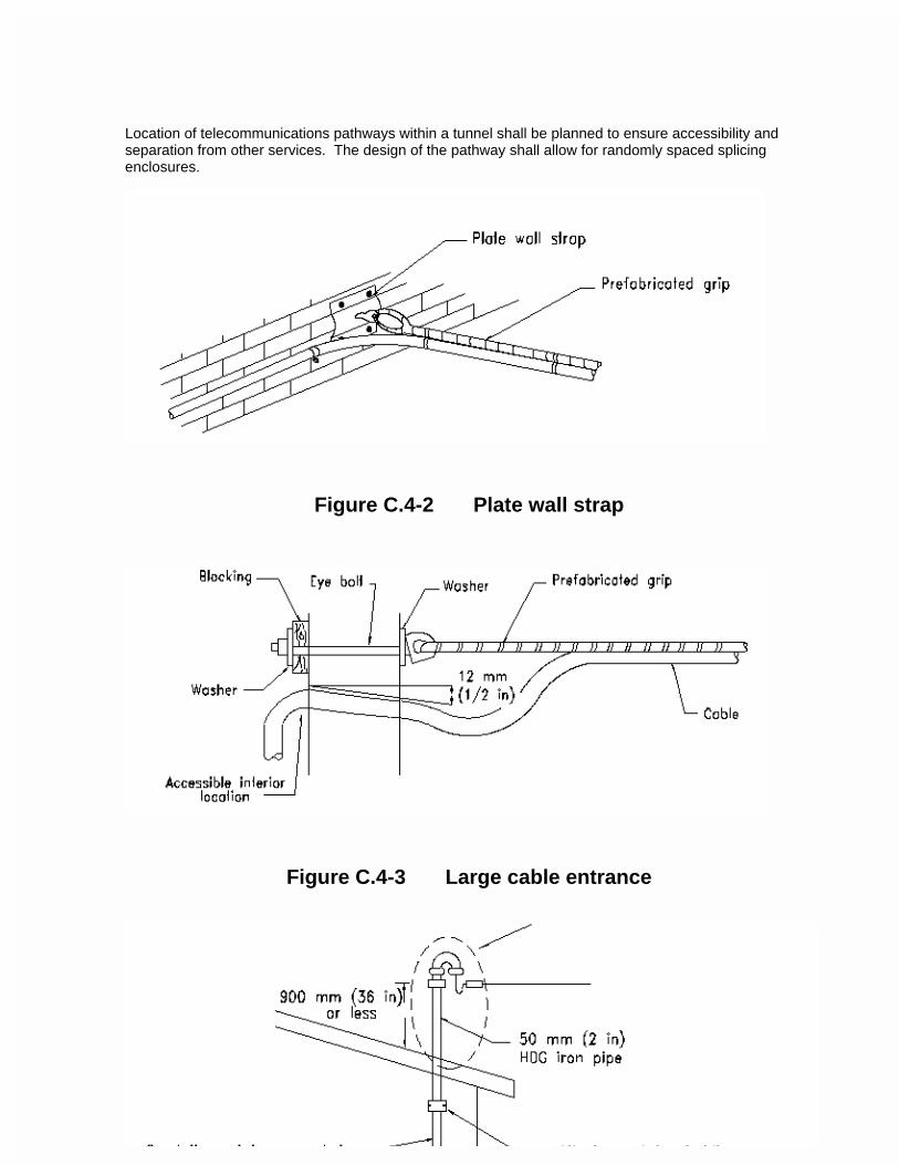
Location of telecommunications pathways within a tunnel shall be planned to ensure accessibility and separation from other services. The design of the pathway shall allow for randomly spaced splicing enclosures.
Figure C.4-2 Plate wall strap
Figure C.4-3 Large cable entrance
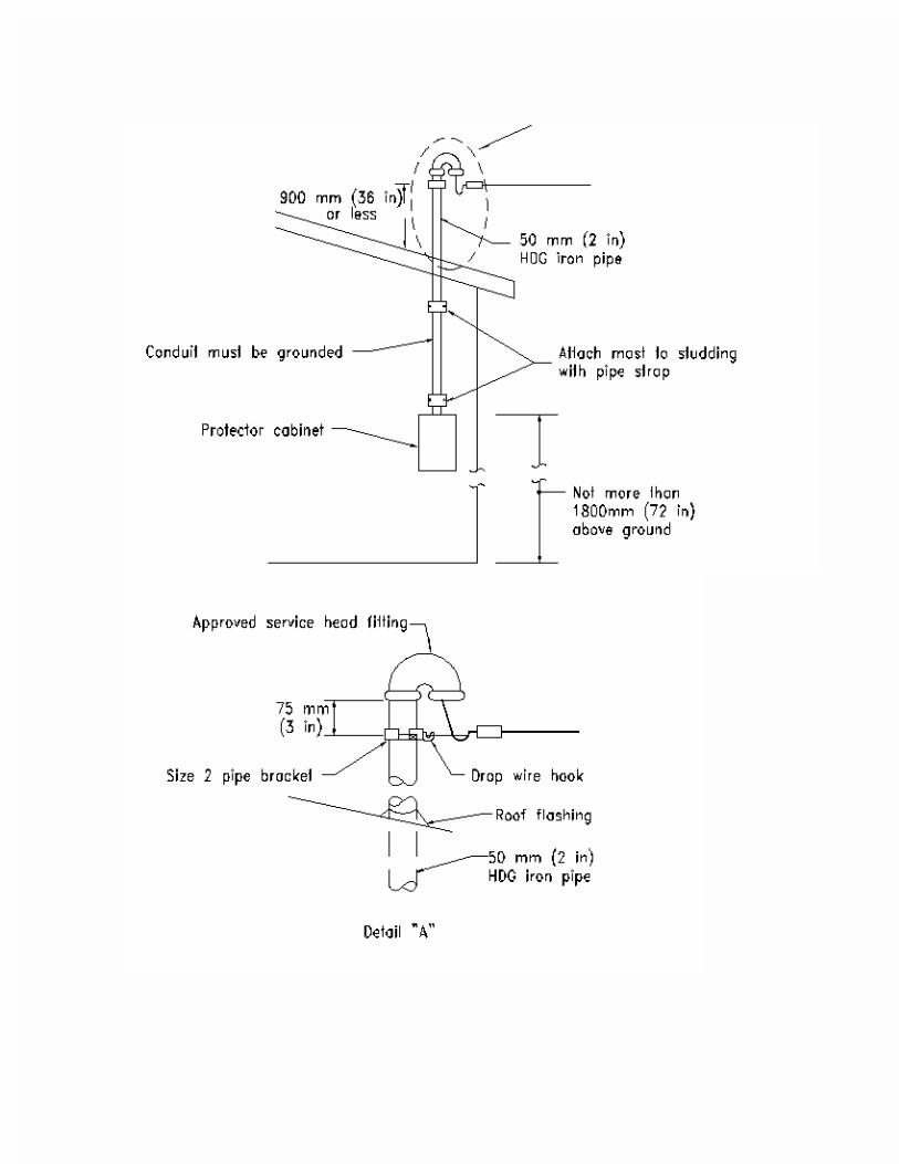
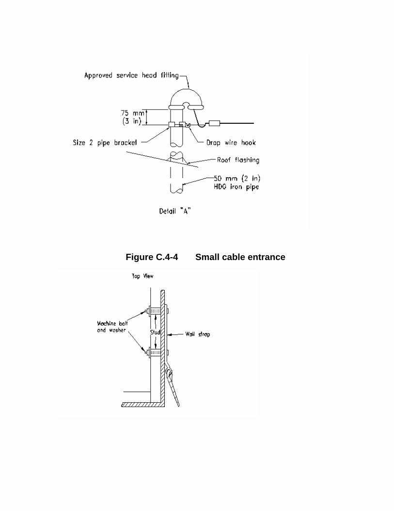
Figure C.4-4 Small cable entrance
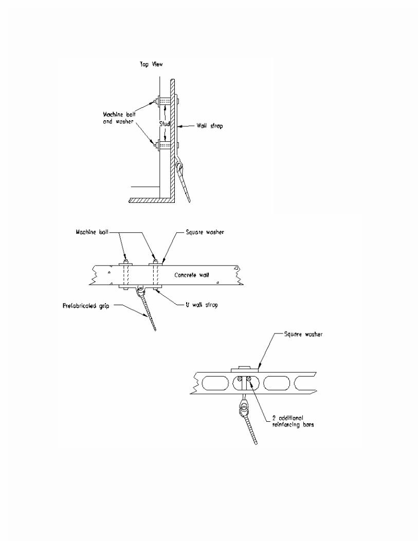
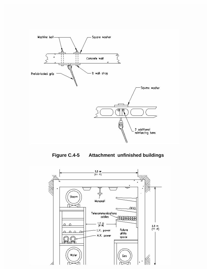
Figure C.4-5 Attachment unfinished buildings
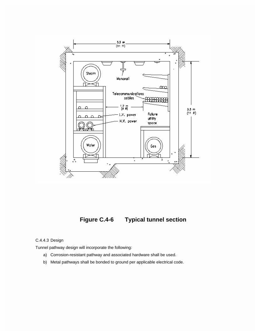
Figure C.4-6 Typical tunnel section
C.4.4.3 Design
Tunnel pathway design will incorporate the following:
a) Corrosion-resistant pathway and associated hardware shall be used.
b) Metal pathways shall be bonded to ground per applicable electrical code.
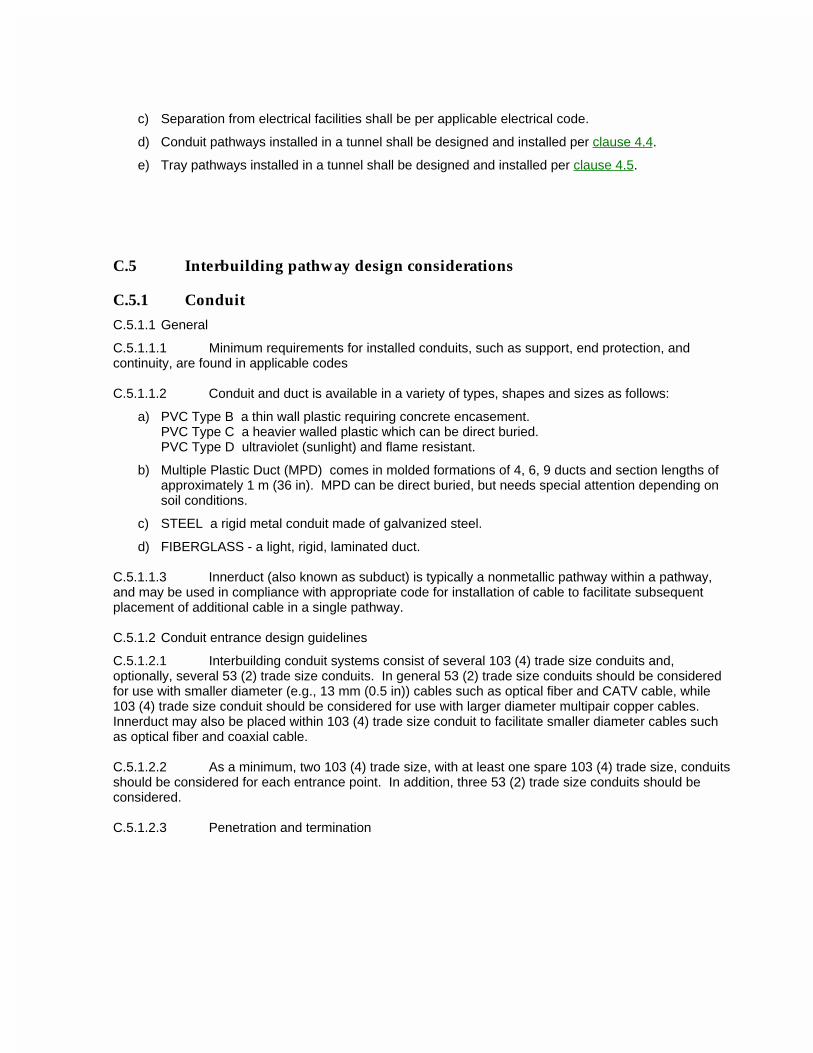
c) Separation from electrical facilities shall be per applicable electrical code.
d) Conduit pathways installed in a tunnel shall be designed and installed per clause 4.4.
e) Tray pathways installed in a tunnel shall be designed and installed per clause 4.5.
C.5 Interbuilding pathway design considerations
C.5.1 Conduit
C.5.1.1 General
C.5.1.1.1 Minimum requirements for installed conduits, such as support, end protection, and continuity, are found in applicable codes
C.5.1.1.2 Conduit and duct is available in a variety of types, shapes and sizes as follows:
a) PVC Type B a thin wall plastic requiring concrete encasement.PVC Type C a heavier walled plastic which can be direct buried.PVC Type D ultraviolet (sunlight) and flame resistant.
b) Multiple Plastic Duct (MPD) comes in molded formations of 4, 6, 9 ducts and section lengths of approximately 1 m (36 in). MPD can be direct buried, but needs special attention depending on soil conditions.
c) STEEL a rigid metal conduit made of galvanized steel.
d) FIBERGLASS - a light, rigid, laminated duct.
C.5.1.1.3 Innerduct (also known as subduct) is typically a nonmetallic pathway within a pathway, and may be used in compliance with appropriate code for installation of cable to facilitate subsequent placement of additional cable in a single pathway.
C.5.1.2 Conduit entrance design guidelines
C.5.1.2.1 Interbuilding conduit systems consist of several 103 (4) trade size conduits and, optionally, several 53 (2) trade size conduits. In general 53 (2) trade size conduits should be considered for use with smaller diameter (e.g., 13 mm (0.5 in)) cables such as optical fiber and CATV cable, while 103 (4) trade size conduit should be considered for use with larger diameter multipair copper cables. Innerduct may also be placed within 103 (4) trade size conduit to facilitate smaller diameter cables such as optical fiber and coaxial cable.
C.5.1.2.2 As a minimum, two 103 (4) trade size, with at least one spare 103 (4) trade size, conduits should be considered for each entrance point. In addition, three 53 (2) trade size conduits should be considered.
C.5.1.2.3 Penetration and termination
The conduit shall extend into undisturbed earth and a minimum of 600 mm (24 in) beyond the exterior of the foundation. When terminated in a pull box, the conduit shall be reamed and bushed. When terminated at the inside of the building wall, the conduit shall have a smooth bell-shaped finish unless it extends to a remote entrance room, space, or area (see figure C.5-1). The conduit or sleeve shall be securely fastened to the building.
Figure C.5-1 Entrance conduit or sleeve termination
C.5.1.3 General conduit design considerations
C.5.1.3.1 Bends
C.5.1.3.1.1 Bends in underground conduit and duct are undesirable. However, when required, bends in conduit and duct runs shall be limited to the equivalent of no more than two 90o bends between pull points (e.g., maintenance hole, handhole).
C.5.1.3.1.2 The inside radius of a bend in conduit shall be at least 6 times the internal diameter. When the conduit size is greater than 53 (2) trade size, the inside radius shall be at least 10 times the internal diameter of the conduit.
C.5.1.3.1.3 Increasing the radius of bends or sweeps significantly extends the length of duct runs between maintenance holes. Figure C.5-2 illustrates the effects of angle or radius on section length between maintenance holes. When bend radii of less than 3 m (10 ft) are used, section lengths are reduced drastically.
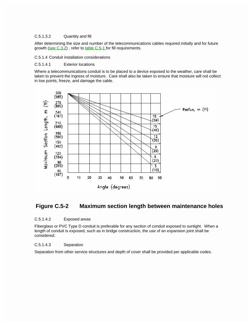
C.5.1.3.2 Quantity and fill
After determining the size and number of the telecommunications cables required initially and for future growth (see C.3.2) , refer to table C.5-1 for fill requirements.
C.5.1.4 Conduit installation considerations
C.5.1.4.1 Exterior locations
Where a telecommunications conduit is to be placed to a device exposed to the weather, care shall be taken to prevent the ingress of moisture. Care shall also be taken to ensure that moisture will not collect in low points, freeze, and damage the cable.
Figure C.5-2 Maximum section length between maintenance holes
C.5.1.4.2 Exposed areas
Fiberglass or PVC Type D conduit is preferable for any section of conduit exposed to sunlight. When a length of conduit is exposed, such as in bridge construction, the use of an expansion joint shall be considered.
C.5.1.4.3 Separation
Separation from other service structures and depth of cover shall be provided per applicable codes.
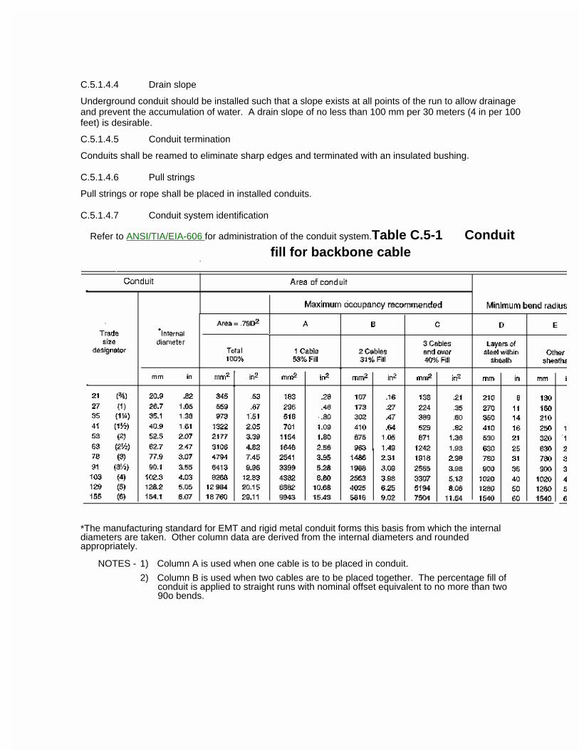
C.5.1.4.4 Drain slope
Underground conduit should be installed such that a slope exists at all points of the run to allow drainage and prevent the accumulation of water. A drain slope of no less than 100 mm per 30 meters (4 in per 100 feet) is desirable.
C.5.1.4.5 Conduit termination
Conduits shall be reamed to eliminate sharp edges and terminated with an insulated bushing.
C.5.1.4.6 Pull strings
Pull strings or rope shall be placed in installed conduits.
C.5.1.4.7 Conduit system identification
Refer to ANSI/TIA/EIA-606 for administration of the conduit system.Table C.5-1 Conduitfill for backbone cable
*The manufacturing standard for EMT and rigid metal conduit forms this basis from which the internal diameters are taken. Other column data are derived from the internal diameters and rounded appropriately.
NOTES - 1) Column A is used when one cable is to be placed in conduit.
2) Column B is used when two cables are to be placed together. The percentage fill of conduit is applied to straight runs with nominal offset equivalent to no more than two 90o bends.
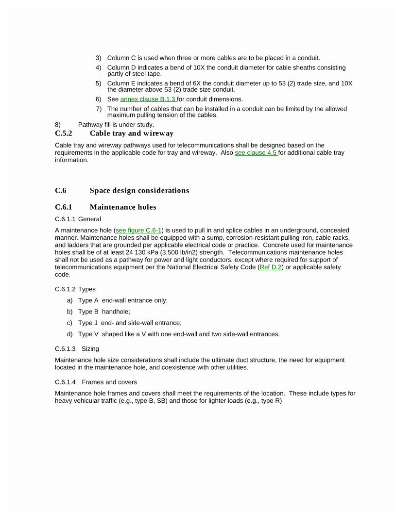
3) Column C is used when three or more cables are to be placed in a conduit.
4) Column D indicates a bend of 10X the conduit diameter for cable sheaths consisting partly of steel tape.
5) Column E indicates a bend of 6X the conduit diameter up to 53 (2) trade size, and 10X the diameter above 53 (2) trade size conduit.
6) See annex clause B.1.3 for conduit dimensions.
7) The number of cables that can be installed in a conduit can be limited by the allowed maximum pulling tension of the cables.
8) Pathway fill is under study.C.5.2 Cable tray and wireway
Cable tray and wireway pathways used for telecommunications shall be designed based on the requirements in the applicable code for tray and wireway. Also see clause 4.5 for additional cable tray information.
C.6 Space design considerations
C.6.1 Maintenance holes
C.6.1.1 General
A maintenance hole (see figure C.6-1) is used to pull in and splice cables in an underground, concealed manner. Maintenance holes shall be equipped with a sump, corrosion-resistant pulling iron, cable racks, and ladders that are grounded per applicable electrical code or practice. Concrete used for maintenance holes shall be of at least 24 130 kPa (3,500 lb/in2) strength. Telecommunications maintenance holes shall not be used as a pathway for power and light conductors, except where required for support of telecommunications equipment per the National Electrical Safety Code (Ref D.2) or applicable safety code.
C.6.1.2 Types
a) Type A end-wall entrance only;
b) Type B handhole;
c) Type J end- and side-wall entrance;
d) Type V shaped like a V with one end-wall and two side-wall entrances.
C.6.1.3 Sizing
Maintenance hole size considerations shall include the ultimate duct structure, the need for equipment located in the maintenance hole, and coexistence with other utilities.
C.6.1.4 Frames and covers
Maintenance hole frames and covers shall meet the requirements of the location. These include types for heavy vehicular traffic (e.g., type B, SB) and those for lighter loads (e.g., type R)
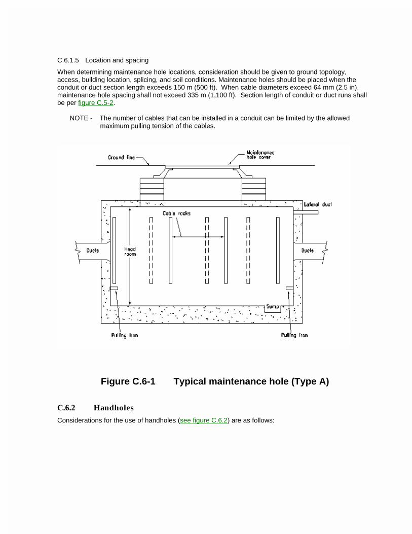
C.6.1.5 Location and spacing
When determining maintenance hole locations, consideration should be given to ground topology, access, building location, splicing, and soil conditions. Maintenance holes should be placed when the conduit or duct section length exceeds 150 m (500 ft). When cable diameters exceed 64 mm (2.5 in), maintenance hole spacing shall not exceed 335 m (1,100 ft). Section length of conduit or duct runs shall be per figure C.5-2.
NOTE - The number of cables that can be installed in a conduit can be limited by the allowed maximum pulling tension of the cables.
Figure C.6-1 Typical maintenance hole (Type A)
C.6.2 Handholes
Considerations for the use of handholes (see figure C.6.2) are as follows:
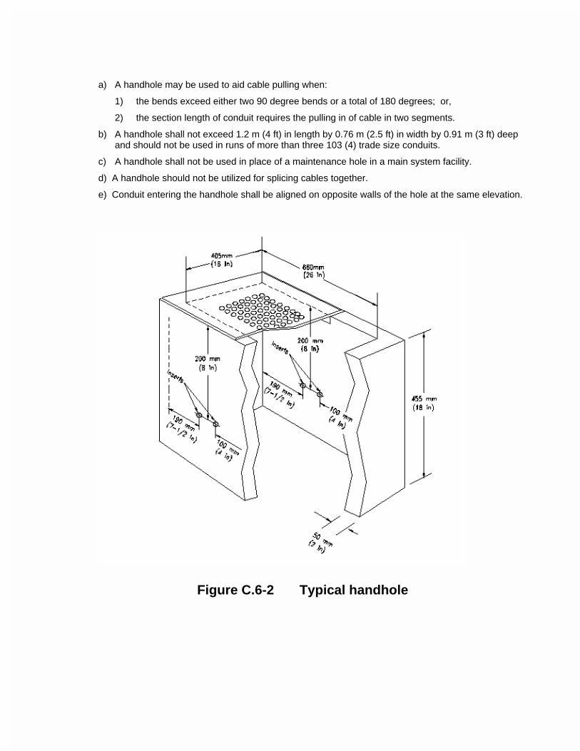
a) A handhole may be used to aid cable pulling when:
1) the bends exceed either two 90 degree bends or a total of 180 degrees; or,
2) the section length of conduit requires the pulling in of cable in two segments.
b) A handhole shall not exceed 1.2 m (4 ft) in length by 0.76 m (2.5 ft) in width by 0.91 m (3 ft) deep and should not be used in runs of more than three 103 (4) trade size conduits.
c) A handhole shall not be used in place of a maintenance hole in a main system facility.
d) A handhole should not be utilized for splicing cables together.
e) Conduit entering the handhole shall be aligned on opposite walls of the hole at the same elevation.
Figure C.6-2 Typical handhole
C.6.3 Pull or splice box design
C.6.3.1 Location
Pull or splice boxes shall be placed in an exposed location, and readily accessible. These are sometimes required in a tunnel or inside or outside a building, but not in earth.
C.6.3.2 Use
C.6.3.2.1 A pull or splice box shall be placed in a conduit run where
a) the length is over 30 m (100 ft);
b) there are more than two 90o bends; or,
c) if there is a reverse (U-shaped) bend in the run.
C.6.3.2.2 Boxes shall be placed in a straight section of conduit and not used in lieu of a bend. The corresponding conduit ends should be aligned with each other. Conduit fittings shall not be used in place of pull boxes.
C.6.3.3 Boxes shall be labeled on the exposed exterior.
ANSI/TIA/EIA-569-AAnnex D (informative)References
This annex is informative only and is not part of this Standard.
D.1 ANSI/IEEE 1100, Recommended Practice for Power and Grounding Sensitive Electronic Equipment in Industrial and Commercial Power Systems (also known as IEEE Emerald Book), Institute of Electrical and Electronic Engineers.
D.2 ANSI/IEEE , National Electrical Safety Code, Institute of Electrical and Electronic Engineers.
D.3 ANSI/NFPA 70, National Electrical Code, National Fire Protection Association.
D.4 ANSI/NFPA 780, Installation of Lightning Protection Systems, National Fire Protection Association.
D.5 ANSI/TIA/EIA-568-A, Commercial Building Telecommunications Cabling Standard, American National Standards Institute, Telecommunications Industry Association and Electronic Industries Association.
D.6 ANSI/TIA/EIA-606, Administration Standard for the Telecommunications Infrastructure of Commercial Buildings, American National Standards Institute, Telecommunications Industry Association and Electronic Industries Association.
D.7 ANSI/TIA/EIA-607, Commercial Building Grounding and Bonding Requirement for Telecommunications, American National Standards Institute, Telecommunications Industry Association and Electronic Industries Association.
D.8 ASTM E 84, Test Method for surface Burning Characteristics of Building Materials, American Society for Testing and Materials.
D.9 ASTM E 119, Fire Tests of Building Construction and Materials, American Society for Testing and Materials.
D.10 ASTM E 814, Fire Tests of Through-Penetration Firestops, American Society for Testing and Materials.
D.11 BICSI, Telecommunications Distribution Methods Manual, Building Industry Consulting Service International.
D.12 CISCA, Recommended Test Procedures for Access Floors, Ceilings and Interior Systems Construction Association.
D.13 EIA EP-7B, Style Manual for Standards and Publications, Electronic Industries Association.
D.14 NEMA OS 1 Sheet Steel Outlet Boxes, Device Boxes, Covers, and Box Supports, National Electrical Manufacturers Association.
D.15 NEMA WD-6, Wiring Devices Dimensional Requirements, National Electrical Manufacturers Association.
D.16 NFPA 255, Surface Burning Characteristics of Building Materials, National Fire Protection Association.
D.17 Uniform Federal Accessibility Standards, General Services Administration.
D.18 UL 1479, Fire Tests of Through-Penetration Firestop, Underwriters Laboratories.
D.19 UL Fire Resistance, Volumes 1 and 2, Underwriters Laboratories.
For additional information about references, contact the respective organizations at the following addresses:
a) ADA Office of Americans with Disabilities ActU.S. Department of Justice, Civil Rights DivisionPO Box 66118Washington DC 20035-6118 USA202-514-0301
b) ANSI American National Standards Institute430 BroadwayNew York NY 10018 USA212-642-4900
c) ASTM American Society for Testing and Materials100 Bar Harbor Drive West Conshohocken PA 19428-2959 USA610-832-9500
d) BICSI Building Industry Consulting Service International10500 University Center Drive, Suite 100Tampa FL 33612-6415 USA813-979-1991
e) CISCA Ceilings and Interior Systems Construction Association104 Wilmot Road, Suite 201Deerfield IL 60015-5195 USA
f) CSA Canadian Standards Association178 Rexdale Blvd.Etobicoke Ontario M9W 1R3 CANADA416-747-4025
g) EIA Electronic Industries Association2500 Wilson Blvd., Suite 400Alexandria VA 22201 USA
h) IEEE Institute of Electrical and Electronic Engineers345 East 47th StreetNew York NY 10017-2394 USA
i) NEMA National Electrical Manufacturers Association1300 North 17th Street, Suite 1847Rosslyn VA 22209 USA703-841-3200
j) NFPA National Fire Protection AssociationBatterymarch ParkQuincy MA 02269 USA
k) TIA Telecommunications Industry Association2500 Wilson Blvd., Suite 300Alexandria VA 22201 USA703-907-7706
l) UFAS Uniform Federal Accessibility StandardsGeneral Services Administration, PTS18th & F Streets, NWWashington DC 20450 USA202-501-0191
m) UL Underwriters Laboratories Inc.333 Pfingsten RoadNorthbrook IL 60062 USA312-272-8800
Related Documents