TI 317 Dante audio networking 1.1 en

Welcome message from author
This document is posted to help you gain knowledge. Please leave a comment to let me know what you think about it! Share it to your friends and learn new things together.
Transcript

TI 317Dante audio networking 1.1 en
Contents1. Audinate Dante...........................................3
2. Dante basics and basic operation................3
2.1 Networking and device discovery.......................................3
2.2 Audio routing and transport in Dante networks..................3
2.3 Methods of transport in Dante networks.............................42.3.1 Unicast and Multicast-flows...............................................42.3.2 IGMP Snooping.................................................................5
2.4 Clock distribution and recovery............................................5
2.5 Redundancy...........................................................................5
2.6 Latency...................................................................................5
3. Network hardware selection.......................7
3.1 Criteria for selection of Dante network switches.................73.1.1 Gigabit Ethernet.................................................................73.1.2 Internal switching bandwidth............................................73.1.3 Management features.......................................................73.1.4 Quality of Service (QoS)..................................................73.1.5 EEE-(Energy Efficient Ethernet)..........................................73.1.6 V-LANs................................................................................83.1.7 IGMP Snooping.................................................................83.1.8 Fibre option........................................................................83.1.9 Road compatible hradware..............................................83.1.10 RSTP (Ring and mesh topologies)...................................9
3.2 Recommended switches for Dante systems..........................93.2.1 Luminex Gigacore series...................................................93.2.2 Yamaha SWP1 series........................................................93.2.3 Cisco SG300 series...........................................................9
4. Troubleshooting........................................10
5. Best Practices............................................12
5.1 Commissioning of Dante networks.....................................12
5.2 Topologies...........................................................................125.2.1 Daisy-Chain.....................................................................125.2.2 Star topology...................................................................125.2.3 Ring/mesh topology........................................................12
TI 317 Dante audio networking 1.1 en 2
1. Audinate DanteAudinate Dante is a combination of protocols, hardwareand software, that are designed for the transport of audioover IP networks. Depending on the hardware and softwareused, up to 512 x 512 audio channels can be transmittedover a single Gigabit Ethernet link. Dante supports samplingrates between 44.1 and 192 kHz and bit depths between16 and 32 Bits per sample. With the DS10 Audio networkbridge, d&b audiotechnik offers an interface between Danteand AES/EBU that is designed for professional use andcompatible with a vast array of third-party products.Within devices, Dante works hardware-based. At the sametime, software-based solutions or “virtual sound cards” arealso available for MacOS and Windows operating systemsto integrate computers into Dante audio systems. In this way,multitrack recording and playback or software audioprocessing is possible through the network without anymedia conversion.
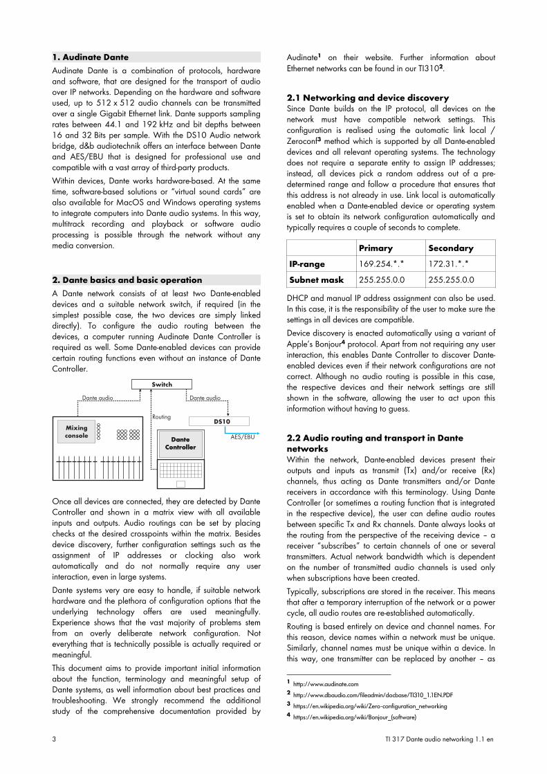
2. Dante basics and basic operationA Dante network consists of at least two Dante-enableddevices and a suitable network switch, if required (in thesimplest possible case, the two devices are simply linkeddirectly). To configure the audio routing between thedevices, a computer running Audinate Dante Controller isrequired as well. Some Dante-enabled devices can providecertain routing functions even without an instance of DanteController.
Once all devices are connected, they are detected by DanteController and shown in a matrix view with all availableinputs and outputs. Audio routings can be set by placingchecks at the desired crosspoints within the matrix. Besidesdevice discovery, further configuration settings such as theassignment of IP addresses or clocking also workautomatically and do not normally require any userinteraction, even in large systems.Dante systems very are easy to handle, if suitable networkhardware and the plethora of configuration options that theunderlying technology offers are used meaningfully.Experience shows that the vast majority of problems stemfrom an overly deliberate network configuration. Noteverything that is technically possible is actually required ormeaningful.This document aims to provide important initial informationabout the function, terminology and meaningful setup ofDante systems, as well information about best practices andtroubleshooting. We strongly recommend the additionalstudy of the comprehensive documentation provided by
Audinate1 on their website. Further information aboutEthernet networks can be found in our TI3102.
2.1 Networking and device discoverySince Dante builds on the IP protocol, all devices on thenetwork must have compatible network settings. Thisconfiguration is realised using the automatic link local /Zeroconf3 method which is supported by all Dante-enableddevices and all relevant operating systems. The technologydoes not require a separate entity to assign IP addresses;instead, all devices pick a random address out of a pre-determined range and follow a procedure that ensures thatthis address is not already in use. Link local is automaticallyenabled when a Dante-enabled device or operating systemis set to obtain its network configuration automatically andtypically requires a couple of seconds to complete.
Primary SecondaryIP-range 169.254.*.* 172.31.*.*Subnet mask 255.255.0.0 255.255.0.0
DHCP and manual IP address assignment can also be used.In this case, it is the responsibility of the user to make sure thesettings in all devices are compatible.Device discovery is enacted automatically using a variant ofApple’s Bonjour4 protocol. Apart from not requiring any userinteraction, this enables Dante Controller to discover Dante-enabled devices even if their network configurations are notcorrect. Although no audio routing is possible in this case,the respective devices and their network settings are stillshown in the software, allowing the user to act upon thisinformation without having to guess.
2.2 Audio routing and transport in DantenetworksWithin the network, Dante-enabled devices present theiroutputs and inputs as transmit (Tx) and/or receive (Rx)channels, thus acting as Dante transmitters and/or Dantereceivers in accordance with this terminology. Using DanteController (or sometimes a routing function that is integratedin the respective device), the user can define audio routesbetween specific Tx and Rx channels. Dante always looks atthe routing from the perspective of the receiving device – areceiver “subscribes” to certain channels of one or severaltransmitters. Actual network bandwidth which is dependenton the number of transmitted audio channels is used onlywhen subscriptions have been created.Typically, subscriptions are stored in the receiver. This meansthat after a temporary interruption of the network or a powercycle, all audio routes are re-established automatically.Routing is based entirely on device and channel names. Forthis reason, device names within a network must be unique.Similarly, channel names must be unique within a device. Inthis way, one transmitter can be replaced by another – as
1 http://www.audinate.com
2 http://www.dbaudio.com/fileadmin/docbase/TI310_1.1EN.PDF
3 https://en.wikipedia.org/wiki/Zero-configuration_networking
4 https://en.wikipedia.org/wiki/Bonjour_(software)
3 TI 317 Dante audio networking 1.1 en
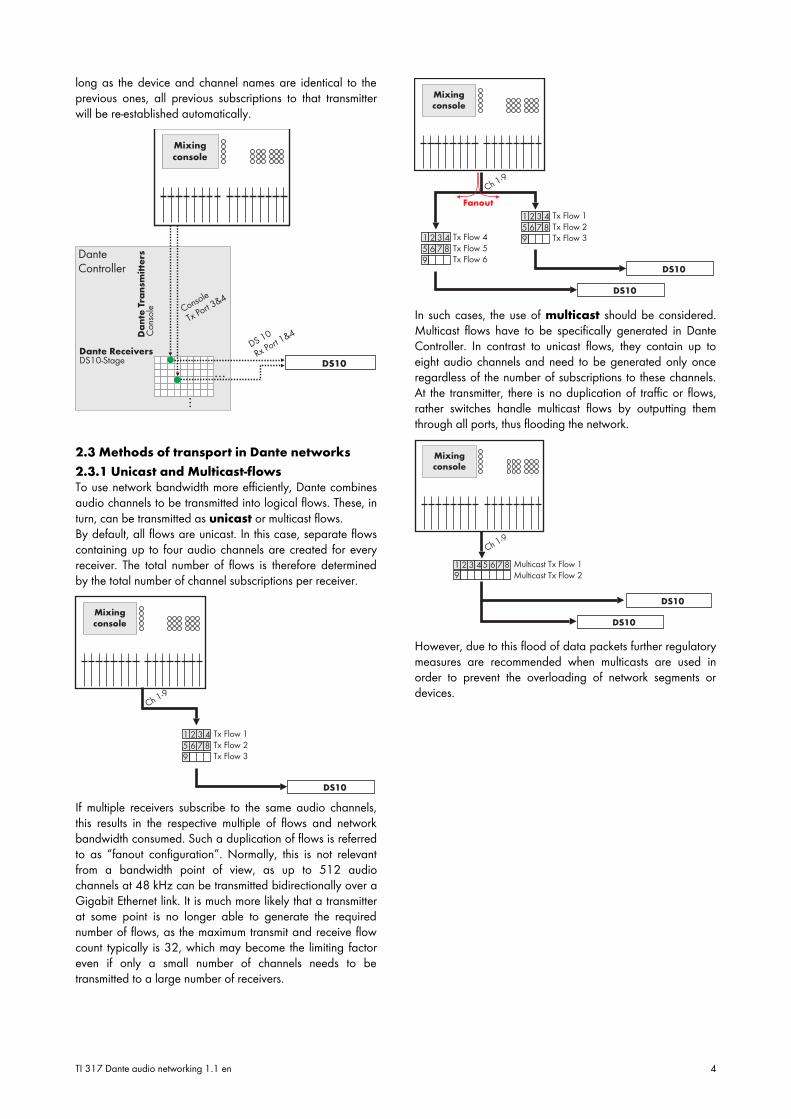
long as the device and channel names are identical to theprevious ones, all previous subscriptions to that transmitterwill be re-established automatically.
2.3 Methods of transport in Dante networks
2.3.1 Unicast and Multicast-flowsTo use network bandwidth more efficiently, Dante combinesaudio channels to be transmitted into logical flows. These, inturn, can be transmitted as unicast or multicast flows.By default, all flows are unicast. In this case, separate flowscontaining up to four audio channels are created for everyreceiver. The total number of flows is therefore determinedby the total number of channel subscriptions per receiver.
If multiple receivers subscribe to the same audio channels,this results in the respective multiple of flows and networkbandwidth consumed. Such a duplication of flows is referredto as “fanout configuration”. Normally, this is not relevantfrom a bandwidth point of view, as up to 512 audiochannels at 48 kHz can be transmitted bidirectionally over aGigabit Ethernet link. It is much more likely that a transmitterat some point is no longer able to generate the requirednumber of flows, as the maximum transmit and receive flowcount typically is 32, which may become the limiting factoreven if only a small number of channels needs to betransmitted to a large number of receivers.
In such cases, the use of multicast should be considered.Multicast flows have to be specifically generated in DanteController. In contrast to unicast flows, they contain up toeight audio channels and need to be generated only onceregardless of the number of subscriptions to these channels.At the transmitter, there is no duplication of traffic or flows,rather switches handle multicast flows by outputting themthrough all ports, thus flooding the network.
However, due to this flood of data packets further regulatorymeasures are recommended when multicasts are used inorder to prevent the overloading of network segments ordevices.
TI 317 Dante audio networking 1.1 en 4
2.3.2 IGMP SnoopingMeaningful use of Multicast requires all backbone switchesto support measures that prevent the simple flooding of thenetwork with data packets. This is why Dante implementsIGMP Snooping (IGMP = Internet Group ManagementProtocol). Switches supporting this feature can handle theforwarding of Multicast data intelligently in such a way thatthey do not simply pass on multicast data to all ports butquery the rest of the network to determine where it isneeded. All of this is performed automatically if IGMPSnooping5 is enabled and, depending on the make andmodel of the switch, if it is configured correctly.
2.4 Clock distribution and recoveryTo enable synchronous playout, every audio system requiresa central clock source. In the case of Dante, every hardwaredevice on the network can assume this role rather thanrequiring a separate device to perform this function. Clockdistribution is facilitated via the network using the PrecisionTime Protocol according to IEEE15886. The samemechanism automatically selects the most stable clocksource. If the connection to this device is lost, a replacementis selected automatically without any interruption to theaudio. The synchronicity of all playout devices is achievedwith a deviation of less than 1 µs.7In order for this to work, all devices have to be configured toclock off the network. Digital mixing consoles are a primeexample – since they also feature an internal clock, theytypically have to be expressly configured to clock off Dante.The automatic clock source selection within a Dante networkcan be monitored and if necessary overridden in DanteController. In this case, the status “Preferred Master” isassigned to the desired device.Clocking to sources outside of the Dante network is alsopossible. For clarity reasons, it should be noted that even theinternal clock of a mixing console, to stay with the aboveexample, is considered as “external” to Dante. In this case,the option “Sync to External” has to be checked in additionto “Preferred Master” for the desired device. Within theconfiguration of this device, the desired clock source canthen be selected (e.g. the internal clock or an external wordclock generator).
Experience shows that forced external clocking more oftenhinders the commissioning of a Dante network thanimproving anything. We therefore recommend only using anexternal clock source if this is technically imperative.
5 https://en.wikipedia.org/wiki/IGMP_snooping
6 https://en.wikipedia.org/wiki/Precision_Time_Protocol
7 To put this in perspective, the duration of a single sample at 96 kHz is 10.42 µs.
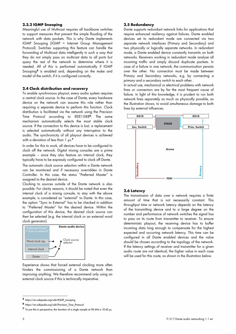
2.5 RedundancyDante supports redundant network links for applications thatrequire enhanced resiliency against failures. Dante enableddevices set to redundant mode are connected via twoseparate network interfaces (Primary and Secondary) andtwo physically or logically separate networks. In redundantmode, a Dante enabled device constantly transmits on bothnetworks. Receivers working in redundant mode analyse allincoming traffic and simply discard duplicate packets. Incase of a failure in one network, the communication persistsover the other. No connection must be made betweenPrimary and Secondary networks, e.g. by connecting aprimary and a secondary switch to each other.In actual use, mechanical or electrical problems with networklines or connectors are by far the most frequent cause offailure. In light of this knowledge, it is prudent to run bothnetwork lines separately as much as physically possible, asthe illustration shows, to avoid simultaneous damage to bothlines by external influences.
2.6 LatencyThe transmission of data over a network requires a finiteamount of time that is not necessarily constant. Thisthroughput time or network latency depends on the latencyof the transmitting device and to a large degree on thenumber and performance of network switches the signal hasto pass on its route from transmitter to receiver. To ensuredeterministic playout, the receiving device has to bufferincoming data long enough to compensate for the highestexpected and occurring network latency. This time can beconfigured in all Dante enabled devices and the valueshould be chosen according to the topology of the network.If the latency settings of receiver and transmitter for a givenaudio route are not identical, the higher value in each casewill be used for this route, as shown in the illustration below.
5 TI 317 Dante audio networking 1.1 en
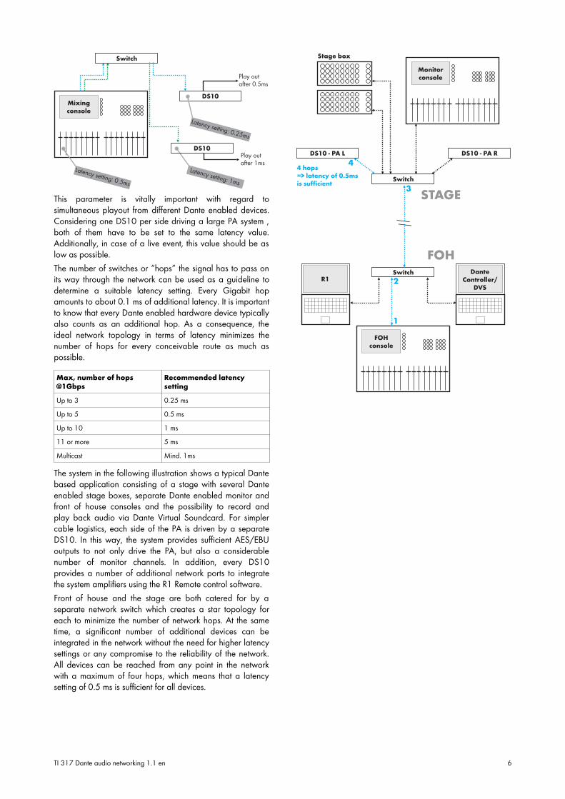
This parameter is vitally important with regard tosimultaneous playout from different Dante enabled devices.Considering one DS10 per side driving a large PA system ,both of them have to be set to the same latency value.Additionally, in case of a live event, this value should be aslow as possible.The number of switches or “hops” the signal has to pass onits way through the network can be used as a guideline todetermine a suitable latency setting. Every Gigabit hopamounts to about 0.1 ms of additional latency. It is importantto know that every Dante enabled hardware device typicallyalso counts as an additional hop. As a consequence, theideal network topology in terms of latency minimizes thenumber of hops for every conceivable route as much aspossible.
Max, number of hops@1Gbps
Recommended latencysetting
Up to 3 0.25 ms
Up to 5 0.5 ms
Up to 10 1 ms
11 or more 5 ms
Multicast Mind. 1ms
The system in the following illustration shows a typical Dantebased application consisting of a stage with several Danteenabled stage boxes, separate Dante enabled monitor andfront of house consoles and the possibility to record andplay back audio via Dante Virtual Soundcard. For simplercable logistics, each side of the PA is driven by a separateDS10. In this way, the system provides sufficient AES/EBUoutputs to not only drive the PA, but also a considerablenumber of monitor channels. In addition, every DS10provides a number of additional network ports to integratethe system amplifiers using the R1 Remote control software.Front of house and the stage are both catered for by aseparate network switch which creates a star topology foreach to minimize the number of network hops. At the sametime, a significant number of additional devices can beintegrated in the network without the need for higher latencysettings or any compromise to the reliability of the network.All devices can be reached from any point in the networkwith a maximum of four hops, which means that a latencysetting of 0.5 ms is sufficient for all devices.
TI 317 Dante audio networking 1.1 en 6
3. Network hardware selectionTo realise a network topology as previously described thatoffers sufficient flexibility, reliability and low latency,additional network switches may be required. In case theport count is sufficient, this functionality can easily beprovided by DS10s. Larger external switches are called forwhen more ports are needed, and special features such asIGMP Snooping are required or when distances of morethan 100 m between switches necessitate the use of fibre-based interconnects. In every case, careful considerationand planning e.g. of the most suitable topology arepreconditions for a meaningful choice.
3.1 Criteria for selection of Dante networkswitchesSuitable criteria for the selection of network switches forDante audio systems can be deduced from the formalrequirements of Dante and the intended use in the eventindustry. Great emphasis lies on establishing high overallnetwork performance and uninterrupted data transmission.
3.1.1 Gigabit EthernetGigabit Ethernet technology is required to make use of thefull potential of Dante. While Fast Ethernet (100 Mbit) linksare technically possible, they considerably reduce theachievable channel count and increase the minimumpossible latency and therefore are not recommended.
3.1.2 Internal switching bandwidthSwitches in Dante networks must be capable of routing full-bandwidth bi-directional traffic of all ports simultaneously.This feature is known as “non-blocking”. Accordingly, an8port Gigabit switch must have an internal switchingcapacity of at least 16 Gbps.
3.1.3 Management featuresManaged switches offer significant flexibility in configuringswitch features based on the requirements of a specificapplication and are therefore recommended by Audinate. Atthe same time, the available options are often fairly complexand require expert knowledge of the specific switch. Also,terminology and feature implementation is not necessarilyconsistent from one manufacturer to another. In practical use,mis- or overconfiguration of switches much more often resultsin network problems than malfunctioning or unsuitablehardware. It is therefore recommended reducing the needfor overly complex network configuration scenarios as muchas possible and configuring switches in a way that allowsthem to be used as “black boxes” that will not requirefrequent reconfiguration.
3.1.4 Quality of Service (QoS)IP networking was not invented with real-time-criticaltransmission of data in mind. Without any further measures,this means that interruptions may occur in Dante applicationsat times of high network load or with conflicting types ofnetwork traffic. To enable deterministic data transmission, a
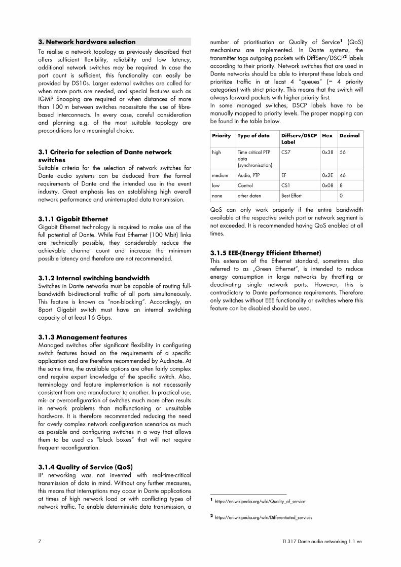
number of prioritisation or Quality of Service1 (QoS)mechanisms are implemented. In Dante systems, thetransmitter tags outgoing packets with DiffServ/DSCP2 labelsaccording to their priority. Network switches that are used inDante networks should be able to interpret these labels andprioritize traffic in at least 4 “queues” (= 4 prioritycategories) with strict priority. This means that the switch willalways forward packets with higher priority first.In some managed switches, DSCP labels have to bemanually mapped to priority levels. The proper mapping canbe found in the table below.
Priority Type of data Diffserv/DSCPLabel
Hex Decimal
high Time critical PTPdata(synchronisation)
CS7 0x38 56
medium Audio, PTP EF 0x2E 46low Control CS1 0x08 8none other daten Best Effort 0
QoS can only work properly if the entire bandwidthavailable at the respective switch port or network segment isnot exceeded. It is recommended having QoS enabled at alltimes.
3.1.5 EEE-(Energy Efficient Ethernet)This extension of the Ethernet standard, sometimes alsoreferred to as „Green Ethernet“, is intended to reduceenergy consumption in large networks by throttling ordeactivating single network ports. However, this iscontradictory to Dante performance requirements. Thereforeonly switches without EEE functionality or switches where thisfeature can be disabled should be used.
1 https://en.wikipedia.org/wiki/Quality_of_service
2 https://en.wikipedia.org/wiki/Differentiated_services
7 TI 317 Dante audio networking 1.1 en
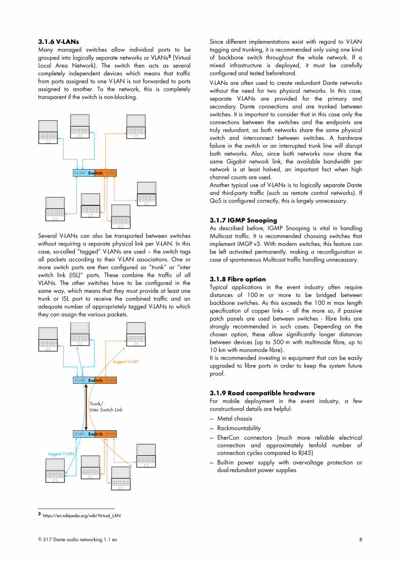
3.1.6 V-LANsMany managed switches allow individual ports to begrouped into logically separate networks or VLANs3 (VirtualLocal Area Network). The switch then acts as severalcompletely independent devices which means that trafficfrom ports assigned to one V-LAN is not forwarded to portsassigned to another. To the network, this is completelytransparent if the switch is non-blocking.
Several V-LANs can also be transported between switcheswithout requiring a separate physical link per V-LAN. In thiscase, so-called “tagged” V-LANs are used – the switch tagsall packets according to their V-LAN associations. One ormore switch ports are then configured as “trunk” or “interswitch link (ISL)” ports. These combine the traffic of allVLANs. The other switches have to be configured in thesame way, which means that they must provide at least onetrunk or ISL port to receive the combined traffic and anadequate number of appropriately tagged V-LANs to whichthey can assign the various packets.
3 https://en.wikipedia.org/wiki/Virtual_LAN
Since different implementations exist with regard to V-LANtagging and trunking, it is recommended only using one kindof backbone switch throughout the whole network. If amixed infrastructure is deployed, it must be carefullyconfigured and tested beforehand.V-LANs are often used to create redundant Dante networkswithout the need for two physical networks. In this case,separate V-LANs are provided for the primary andsecondary Dante connections and are trunked betweenswitches. It is important to consider that in this case only theconnections between the switches and the endpoints aretruly redundant, as both networks share the same physicalswitch and interconnect between switches. A hardwarefailure in the switch or an interrupted trunk line will disruptboth networks. Also, since both networks now share thesame Gigabit network link, the available bandwidth pernetwork is at least halved, an important fact when highchannel counts are used.Another typical use of V-LANs is to logically separate Danteand third-party traffic (such as remote control networks). IfQoS is configured correctly, this is largely unnecessary.
3.1.7 IGMP SnoopingAs described before, IGMP Snooping is vital in handlingMulticast traffic. It is recommended choosing switches thatimplement IMGP v3. With modern switches, this feature canbe left activated permanently, making a reconfiguration incase of spontaneous Multicast traffic handling unnecessary.
3.1.8 Fibre optionTypical applications in the event industry often requiredistances of 100 m or more to be bridged betweenbackbone switches. As this exceeds the 100 m max lengthspecification of copper links – all the more so, if passivepatch panels are used between switches - fibre links arestrongly recommended in such cases. Depending on thechosen option, these allow significantly longer distancesbetween devices (up to 500 m with multimode fibre, up to10 km with monomode fibre).It is recommended investing in equipment that can be easilyupgraded to fibre ports in order to keep the system futureproof.
3.1.9 Road compatible hradwareFor mobile deployment in the event industry, a fewconstructional details are helpful:— Metal chassis
— Rackmountability
— EherCon connectors (much more reliable electricalconnection and approximately tenfold number ofconnection cycles compared to RJ45)
— Built-in power supply with overvoltage protection ordual-redundant power supplies
TI 317 Dante audio networking 1.1 en 8
3.1.10 RSTP (Ring and mesh topologies)RSTP4 (Rapid Spanning Tree Protocol) allows the creation ofring and mesh topologies for enhanced resilience againstinterrupted backbone links. In order for this to work, RSTPmust be supported by all switches that are part of the loop ormesh. Should a network link fail, the switches canautomatically reroute traffic through a redundant link.Depending on the model of the switch, this procedure maystill cause an interruption of several seconds. Also,depending on the make and model of the switch, configuringRSTP may be non-trivial and should be thoroughlyunderstood.
3.2 Recommended switches for Dante systemsThe following recommendations are limited to only a fewdevices and are not exhaustive. The recommended modelshave been chosen based on application relevant features,ease-of-use and market presence. All device series eitherfeature a chassis-mounted road-worthy fibre connector orcan be upgraded accordingly using an additional break-outpanel.
3.2.1 Luminex Gigacore seriesThese switches have been specifically developed for theevent industry and are ideally configured for Dante systemsout of the box or after a factory reset. Additionally, theysupport arbitrary mesh or ring topologies without any furtherconfiguration and feature a very short rerouting time whenswapping links (no or nearly no audible artefacts whileopening or closing a network ring).
3.2.2 Yamaha SWP1 seriesThese switches have also been specifically designed forDante systems and are very easy to configure. Variouspresets are recallable by simple dip switches on the frontpanel without any software configuration.Both previously mentioned product series not only stand outbecause of their technical features, but also due to theirmeaningful preconfigurations and very easy adaptability todifferent application scenarios.
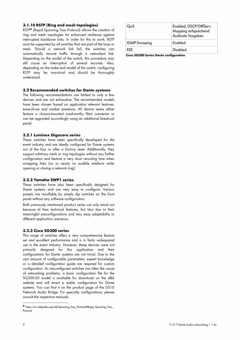
3.2.3 Cisco SG300 seriesThis range of switches offers a very comprehensive featureset and excellent performance and is in fairly widespreaduse in the event industry. However, these devices were notprimarily designed for this application and theirconfigurations for Dante systems are not trivial. Due to thevast amount of configurable parameters, expert knowledgeor a detailed configuration guide are required for customconfiguration. As misconfigured switches are often the causeof networking problems, a basic configuration file for theSG300-20 model is available for download on the d&bwebsite and will enact a stable configuration for Dantesystems. You can find it on the product page of the DS10Network Audio Bridge. For specialty configurations, pleaseconsult the respective manuals.
4 https://en.wikipedia.org/wiki/Spanning_Tree_Protocol#Rapid_Spanning_Tree_
Protocol
QoS Enabled, DSCP/DiffServMapping entsprechendAudinate Vorgaben
IGMP Snooping Enabled
EEE Disabled
Cisco SG300 Series Dante configuration
9 TI 317 Dante audio networking 1.1 en
4. Troubleshooting
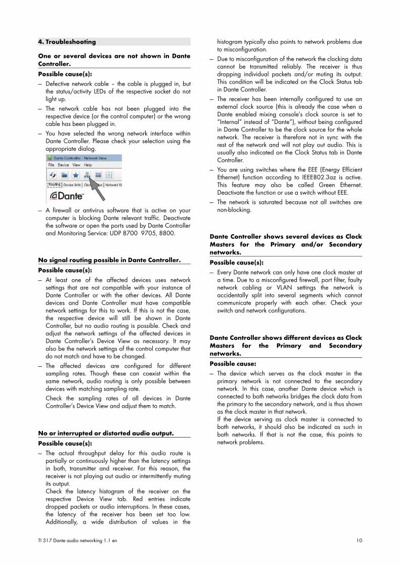
One or several devices are not shown in DanteController.Possible cause(s):— Defective network cable – the cable is plugged in, but
the status/activity LEDs of the respective socket do notlight up.
— The network cable has not been plugged into therespective device (or the control computer) or the wrongcable has been plugged in.
— You have selected the wrong network interface withinDante Controller. Please check your selection using theappropriate dialog.
— A firewall or antivirus software that is active on yourcomputer is blocking Dante relevant traffic. Deactivatethe software or open the ports used by Dante Controllerand Monitoring Service: UDP 8700 9705, 8800.
No signal routing possible in Dante Controller.Possible cause(s):— At least one of the affected devices uses network
settings that are not compatible with your instance ofDante Controller or with the other devices. All Dantedevices and Dante Controller must have compatiblenetwork settings for this to work. If this is not the case,the respective device will still be shown in DanteController, but no audio routing is possible. Check andadjust the network settings of the affected devices inDante Controller’s Device View as necessary. It mayalso be the network settings of the control computer thatdo not match and have to be changed.
— The affected devices are configured for differentsampling rates. Though these can coexist within thesame network, audio routing is only possible betweendevices with matching sampling rate.
Check the sampling rates of all devices in DanteController’s Device View and adjust them to match.
No or interrupted or distorted audio output.Possible cause(s):— The actual throughput delay for this audio route is
partially or continuously higher than the latency settingsin both, transmitter and receiver. For this reason, thereceiver is not playing out audio or intermittently mutingits output.Check the latency histogram of the receiver on therespective Device View tab. Red entries indicatedropped packets or audio interruptions. In these cases,the latency of the receiver has been set too low.Additionally, a wide distribution of values in the
histogram typically also points to network problems dueto misconfiguration.
— Due to misconfiguration of the network the clocking datacannot be transmitted reliably. The receiver is thusdropping individual packets and/or muting its output.This condition will be indicated on the Clock Status tabin Dante Controller.
— The receiver has been internally configured to use anexternal clock source (this is already the case when aDante enabled mixing console’s clock source is set to“Internal” instead of “Dante”), without being configuredin Dante Controller to be the clock source for the wholenetwork. The receiver is therefore not in sync with therest of the network and will not play out audio. This isusually also indicated on the Clock Status tab in DanteController.
— You are using switches where the EEE (Energy EfficientEthernet) function according to IEEE802.3az is active.This feature may also be called Green Ethernet.Deactivate the function or use a switch without EEE.
— The network is saturated because not all switches arenon-blocking.
Dante Controller shows several devices as ClockMasters for the Primary and/or Secondarynetworks.Possible cause(s):— Every Dante network can only have one clock master at
a time. Due to a misconfigured firewall, port filter, faultynetwork cabling or VLAN settings the network isaccidentally split into several segments which cannotcommunicate properly with each other. Check yourswitch and network configurations.
Dante Controller shows different devices as ClockMasters for the Primary and Secondarynetworks.Possible cause:— The device which serves as the clock master in the
primary network is not connected to the secondarynetwork. In this case, another Dante device which isconnected to both networks bridges the clock data fromthe primary to the secondary network, and is thus shownas the clock master in that network.If the device serving as clock master is connected toboth networks, it should also be indicated as such inboth networks. If that is not the case, this points tonetwork problems.
TI 317 Dante audio networking 1.1 en 10

Some parameters of a device are greyed out inDante Controller and cannot be modified.Possible cause(s):— The respective features are not available on that device.
— Operating the respective features via Dante Controller isnot possible with the device. Consult the respective usermanual for further information.
— The device network settings are not correctly made.Check and adjust the network settings of the affecteddevices in Dante Controller’s Device View as necessary.It may also be the network settings of the controlcomputer that do not match and have to be changed.
11 TI 317 Dante audio networking 1.1 en
5. Best Practices5.1 Commissioning of Dante networks
When planning larger networks, draw a plan ofthe topology first.Mapping out the network first will give you a much betteridea of how many and where switch ports are needed andwhat the cable runs will have to be.
Make use of Dante’s automatic configurationmechanisms, configure manually only whenabsolutely necessary.Network configuration and clocking work automatically andreliably in Dante networks. Manual configuration of thesesettings is usually not necessary for proper operation.
Before using redundant networks, check bothindividually.Connect only the primary interfaces first and check thenetwork. Repeat the procedure with the secondaryconnections only. Connect both networks if they haveworked individually.The “Clock Status” and “Network Status” tabs in DanteController will give you further detailed information aboutthe status of network links and clock distribution/stability ofthe network.
5.2 TopologiesDifferent topologies can be realized within IP networks. Thissection outlines several basic variants with regard to their usein Dante networks.
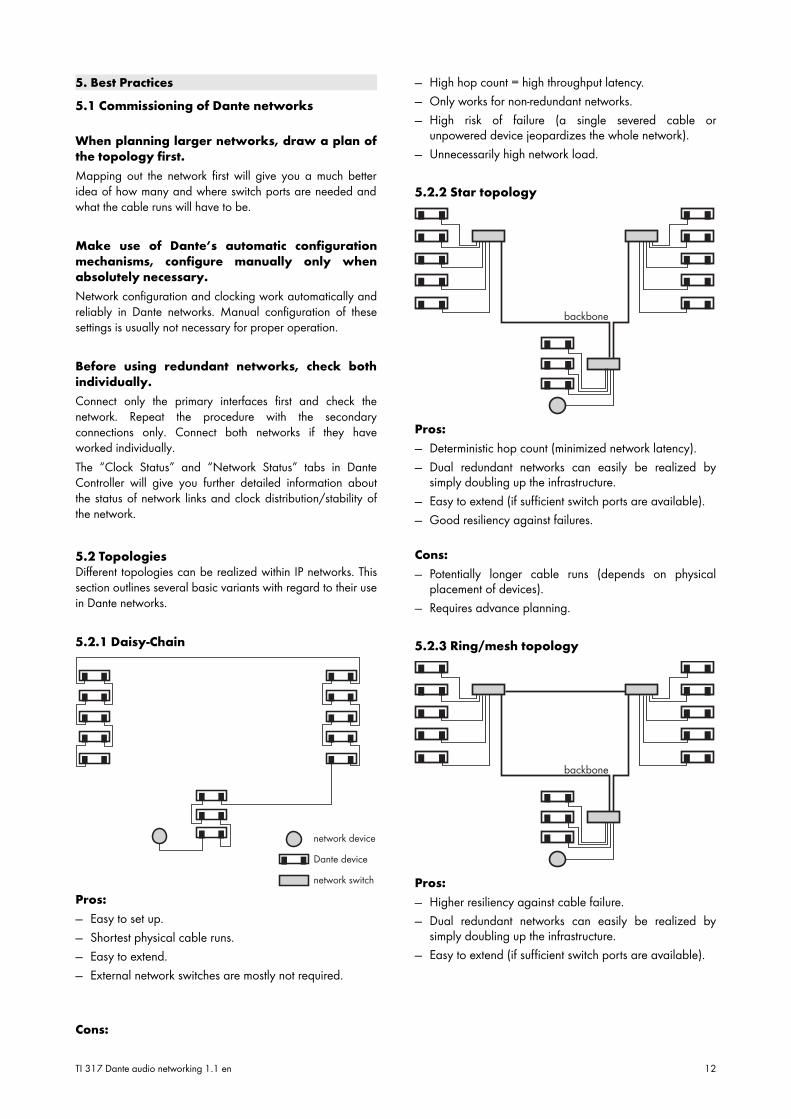
5.2.1 Daisy-Chain
Pros:— Easy to set up.
— Shortest physical cable runs.
— Easy to extend.
— External network switches are mostly not required.
Cons:
— High hop count = high throughput latency.
— Only works for non-redundant networks.
— High risk of failure (a single severed cable orunpowered device jeopardizes the whole network).
— Unnecessarily high network load.
5.2.2 Star topology
Pros:— Deterministic hop count (minimized network latency).
— Dual redundant networks can easily be realized bysimply doubling up the infrastructure.
— Easy to extend (if sufficient switch ports are available).
— Good resiliency against failures.
Cons:— Potentially longer cable runs (depends on physical
placement of devices).
— Requires advance planning.
5.2.3 Ring/mesh topology
Pros:— Higher resiliency against cable failure.
— Dual redundant networks can easily be realized bysimply doubling up the infrastructure.
— Easy to extend (if sufficient switch ports are available).
TI 317 Dante audio networking 1.1 en 12
Cons:
— Requires correct configuration of RSTP in all backboneswitches.
— Depending on the make and model of the backboneswitches, an interruption of one backbone link may stillproduce a noticeable interruption of the network whiletraffic is rerouted.
13 TI 317 Dante audio networking 1.1 en

D5
31
7.E
N. 0
1, 0
4/
20
16
© d
&b
aud
iote
chni
k G
mb
H
d&b audiotechnik GmbH, Eugen-Adolff-Strasse 134, D-71522 Backnang, Germany, Phone +49-7191-9669-0, Fax +49-7191-95 00 00
Related Documents