THE MARQUARDT CORPORATION /- 15 JULY 1963 FINAL REPORT THRUST CHAMBER COOLING TECHNIQUES FOR SPACECRAFT ENGINES CONTRACT NUMBER NAS-7-103 PROJECT NUMBER 278 REPORT 5981 VOLUME I https://ntrs.nasa.gov/search.jsp?R=19630011163 2018-08-25T19:00:32+00:00Z

Welcome message from author
This document is posted to help you gain knowledge. Please leave a comment to let me know what you think about it! Share it to your friends and learn new things together.
Transcript
THE MARQUARDT CORPORATION
/-
15 JULY 1963
FINAL REPORT
THRUST CHAMBER
COOLING TECHNIQUESFOR SPACECRAFT ENGINES
CONTRACT NUMBER NAS-7-103PROJECT NUMBER 278
REPORT 5981 VOLUME I
https://ntrs.nasa.gov/search.jsp?R=19630011163 2018-08-25T19:00:32+00:00Z

DATE 15 July 1963
I I II
REPORT
6I
5981
VOL.
I
l
UNCLASSIFIED
(Title -- Unclassified)
FINAL REPORT
THRUST CHAMBER COOLING TECHNIQUES
FOR SPACECRAFT ENGINES
for the Period
13 February 1962 to IZ February 1963
VOLUME I
EVALUATION PROCEDURE AND ANALYSES
Contract NAS 7- 103
Project 278
PREPARED BY
D oP,°Batha,
C _ _bo_° Cam ell,
UG r/M.D. Car_
C.D. Coulbert
APPROVED BY
M.E.Goodhart
Senior Project Engineer
Advanced Technology Development
CHECKED BY
C,,Do Coulbert
Project Engineer
UNCLASSIFIED
VAN NUYS, CALIFORNIA


UNCLASSIFIED VAN N_S. _UFOe'IA I_ VOL_ I
CONTENTS
Section
I
II
III
IV
V
VI
Page
SUMMARY ............................. i
INTRODUCTION ........................... 2
A. Program Objectives ...................... 2
B. Scope of Mission Requirements and Engine Types ...... 2
C. Program Approach ....................... 2
D. Effect of State of the A_t Advances on the Results
of the Program ....................... 3
E° Cooling Techniques ...................... 3
F. Sources of Data ....................... 3
G. Specific Design Studies .................. 4
H. Limitations and Interpretations of Results .......... 4
SUMMARY OF PROCEDURE FOR SELECTION OF A THRUST CHAMBER
COOLING METHOD .......................... 5
PROI_JLSION SYSTEM SPECIFICATION ................. 6
A° Mission Requirements ..................... 66B. Propellants ........................
C. Propulsion Requirements .................. 7
D. Environmental and Operational Requirements .......... 8
GENERAL APPLICABILITY CHARACTERISTICS OF THRUST CHAMBER
COOLING METHODS .......................
Ao Cooling Techniques Applicable to Particular Propulsion
Requirements ......................... 9
B. Applicability of Specific Cooling Techniques ......... ].2
PRELIMINARY THRUST CHAMBER WEIGHT ANALYSIS ............ 23
A. Typical Thrust Chamber Configurations ............ 23
B. Weights of Regeneratively Cooled Thrust Chambers ....... 24
C. Weights of Radiation Cooled Thrust Chambers ......... 25
D. Weights of Ablative Thrust Chambers ............. 26
IINCI A._SIFIED - i -

UNCLASSIFIED VAN NUY$o CALIFOINIAU
5981VOL. I
Section
VII
VIII
IX
CONTENTS (Continued)
PROPULSION PERFORMANCE PENALTIES ................
A. Isp Losses Due to Film and Transpiration Cooling ......
B. Thrust and Isp Changes Due to Throat Erosion ....... .
C. Heat Losses and Pressure Losses ..............
D. Residual Thrust in Ablative Engines ............E. Optimum Exit Nozzle Expansion Ratio versus Engine
Performance, Weight and Size ................
DESIGN STUDIES AND FACTORS AFFECTING FINAL CHOICE OF COOLINGMETHOD .............................
Ao Design Studies .......................
Bo Combined Cooling Techniques and Advanced Concepts .....
REFERENCES ..........................
TABLE I -- Summary of Spacecraft Missions and Propulsion
System Requirements ................
TABLE II -- Effect of Propellant Choice on Cooling
Technique Applicability ..............
APPENDIX A -- Summary of Nomenclature .............
Page
27
27
27
2728
28
3o
3o
43
44
45
93
DISTRIBUTION .......................... 96
!
UNCLASSIFIED - ii-

UNCLASSIFIED_ 9981
VAN Nlrfs, CAUIq:)I'NIAVOL. I
1.
2.
3.
4.
6.
To
8.
9.
i0.
ll.
12.
13.
14.
15.
16.
17.
18.
19.
ILLUSTRATIONS
Thrust, Time, and Impulse Values .................
Typical Thrust-Time Plots for Space Engine Missions ....... 47
Cooling Method Screening Chart .................. 48
Typical Thrust Chamber Configurations for Space Engine
Application ........................... 49
Feasibility Map for Regenerative Cooling ............. 50
Equilibrium Wall Temperatures for Thin Wall, Radiation Cooled
Chamber and Exit Nozzle ..................... 51
Limiting Chamber Pressure for Radiation Cooling ........ 52
Compilation of Test Data for Ablative Refrasil Phenolic ..... 53
Reslduel Total Impulse Due to Postrun Charring of a Reinforced
Phenolic Thrust Chamber ..................... 54
Decrease of Motor Performance with Film Cooling ......... 55
Temperature Response of Uncooled Heat Sink Exit Nozzle Inserts.. 56
Temperature Response of Uncooled Heat Sink Exit Nozzle Inserts.. 57
Assumed Relationship Between L* and Throat Area Based on Data
from Several Developed Thrust Chamber Designs .......... 58
Thrust Variation with Expansion Ratio and Propellant ....... 99
Thrust Variation with Chamber Pressure and Throat Diameter .... 60
Variation of Expansion Nozzle Length with Throat Diameter .... 61
Variation of Surface Area of Combustion Chamber Elements with
Throat Diameter ......................... 62
Variation of Surface Area of Expansion Nozzle Elements with
Throat Diameter ......................... 63
Thrust Chamber Weights for a Long Run, Throttling Engine ..... 64
Page
46
UNCLASSIFIED - iii -
UNCLASSIFIED VAN NUVS.CAUeOm_,A meeo_r, 5981VOL. I
20.
21.
22.
23.
24.
25.
26.
27.
28.
29.
30.
31.
32.
ILLUSTRATIONS (Continued)
Page
Thrust Chamber Weights for Constant Total Impulse Engine ..... 65
Thrust and Burning Time Envelopes for Minimum Weight
Space Engines ......................... 66
Construction Used in Weight Analysis of a Typical Regeneratively
Cooled Thrust Chamber ...................... 67
Reinforcement Weight Upstream from Nozzle Throat,Contraction Ratio = 2:1 ..................... 68
Reinforcement Weight Upstream from Nozzle Throat,
Contraction Ratio = 4:1 ..................... 69
Reinforcement Weight Downstream from Nozzle Throat ........ 70
Coolant Passage Weight Upstream from Nozzle Throat ........ 71
Regenerative Cooling Passage and Extension Weight Downstream
from Nozzle Throat to Nozzle Exit Plane ............. 72
Fuel Manifold Weight for N2H 4 and Aerozine-50 Cooled Chambers . . 73
Fuel Manifold Weight for Hydrogen Cooled Chambers ........ 74
Coolant Weight Based on Jacket Volume Upstream from Nozzle
Throat ............................ 75
Coolant Weight Based on Jacket Volume Downstream from Nozzle
Throat .............................. 76
Coolant Weight Based on Fuel Manifold Volume for Aerozine-50
and N2H 4 .......................... 77
Coolant Weight Based on Fuel Manifold Volume for Hydrogen .... 78
Regeneratively Cooled Thrust Chamber Weights for Several
Chamber Pressures and Expansion Ratios .............. 79
Weight of Radiation Cooled Thrust Chamber Using 90Ta-10W Alloy. 80
Weight of Radiation Cooled Thrust Chamber Using 90 Ta-lOW
and Haynes 25 Alloys ...................... 81
!
UN-CLASSIF! ED - iV -

UNCLASSIFIED
ILLUSTRATIONS (Continued)
Figure
37.
38.
39.
40.
41.
42.
45.
Characteristic Ablative Thrust Chamber Weight as a Function of
Thrust for 60-second Steady State Run ..............
Characteristic Ablative Thrust Chamber Weight as a Function of
Thrust for 300-second Steady State Run ..............
Characteristic Ablative Thrust Chamber Weight as a Function of
Thrust for 600-second Steady State Run ..............
Characteristic Ablative Thrust Chamber Weight as a Function of
Thrust for lO00-second Steady State Run ..............
Variation of Ablative Thrust Chamber Weight Parameter with
Throat Diameter .........................
Design Layout for Weight Analysis of a Typical Ablative
Thrust Chamber Design ......................
Rocket Engine Performance Variation with Coolant Film Thickness
Variation of Performance Parameter Due to Rocket Nozzle
Throat Enlargement ........................
Variation of Typical Required Minimum Impulse Bits with Thrust
Level for Attitude Control Rocket Engines ............
Variation of Specific Impulse with Nozzle Expansion Ratio ....
Film Cooling Requirement for Total Surface Area .........
Page
82
83
84
85
86
87
88
89
9o
91
92
UNCLASSIFIED - v -

UNCLASSIFIED VAN NUYS, CALIFORNIA REPORT9981
VO/,. I
I. SUMMARY
Space missions envisioned for liquid propellant rocket engines en-
compass a wide spectrum of performance and structural requirements. Thrust levels
from a few pounds to many thousands of pounds per engine and run times from frac-
tions of a second to many minutes may be required. Installations vary from those
in which the engine is free to radiate heat to space to those in which the engine
must be buried within the vehicle. The most promising propellants include the
storable hypergolics as well as the cryogenic high energy combinations.
All of these spacecraft engines have one problem in common: The
energy generated by the propellants must be contained and the surrounding structure
must be protected. The materials involved must be able to withstand the high tem-
perature of the combustion gases or must be cooled to safe operating temperatures.
Thrust chamber cooling concepts developed to cope with these require-
ments either singly or in combination include regenerative or convective cooling,
radiation cooling, film or transpiration cooling, ablation, and inert or endother-
mic heat sinks.
This report is composed of two volumes and it presents a study of the
range and limits of applicability of each of these cooling concepts and procedures
for selecting and designing the most suitable cooling system for a specific space-
craft engine application.
Volume I of this report outlines the procedure proposed for evaluating
the cooling requirements for a liquid rocket space engine and provides analyses and
data for selecting the applicable and best cooling techniques. Four specific
examples of propulsion requirements are used to demonstrate the cooling technique
selection procedure.
Volume II of this report presents thrust chamber design procedures
for each cooling technique, including design data for propellants and thrust
chamber materials, as well as additional details of mission requirements and a
bibliography arranged by subject entries.
It is the hope of the authors that this report will be useful for
several years to come. It is realized, however, that the work presented here is
subject to constant updating as a function of new materials and fabrication capa-
bilities and design techniques. The bibliography presented in Volume II should be
used to supplement this report by providing additional detail design and test data
for specific areas of interest.
Technical areas requiring continued intensive research and development
include high temperature refractory material systems for uncooled nozzle throat in-
serts and the application of film and transpiration cooling to high pressure, high
temperature, corrosive combustion gas propulsion systems.
U
LJNCLASSIFIED - i -
UNCLASS IFIED
_a
VAN NUYS, CALIFOaNIA JEPOIIT5981
voL. i
II. INTRODUCTION
A. Program Objectives
A program to facilitate the selection and design of the most suitable
cooling method for various spacecraft liquid rocket engines has been sponsored by
the National Aeronautics and Space Administration, Office of Liquid Rockets, under
Contract NAS 7-103.
The objectives of the program conducted under this contract were:
To determine the applicability and limitations of the various
thrust chamber cooling methods for liquid propellant rocket
engines used to fulfill spacecraft propulsion requirements
. To present thrust chamber design procedures for each cooling
technique and to provide a basis for comparing different cooling
designs on the basis of applicability, weight, and performance
, To develop and present a rapid and convenient procedure for
selecting the most suitable cooling method for the various
spacecraft engine applications
B. S£ope of Mission Requirements and Engine T_es
The scope of space missions and engine types considered includes mis-
sions that can be carried out with Centaur, Saturn, and Nova class vehicles. The
engine applications include those which would provide the propulsion needed to ac-
complish orbital or trajectory correction, orbital rendezvous, and lunar and
planetary landing and takeoff. The engine types have been limited to those using
liquid propellants. Engine sizes considered in detail have been those in the i00
to 20,000 pound thrust class, although the results and conclusions apply over a
much wider range of sizes.
C. Program Approach
The technical approach employed to accomplish the objectives of this
program has been to evaluate each available cooling technique to define its range
of application and the nature of the limitations of its applicability. The cur-
rently available experimental data and technical data on mission requirements, pro-
pellant performance, cooling systems, and structural materials have been evaluated
for their relationship to the selection of a cooling technique and design of a
rocket engine thrust chamber.
Parameter studies have been conducted to define the range of capabili-
ties of each cooling method and to permit a comparison of different cooling methods
for a particular application.
UNCLASSIFIED - 2 -

UNCLASS IFIED VAN NUYS,CAU_Om.IA a_POJtT _981vcL. I
D. Effect of State of the Art Advances on the Results of the Program
An attempt has been made in presenting the results of this program to
provide for advances in the state of the art in the next several years in the areas
of improved materials, propellants, or new mission requirements. This has been
done by including the basic thrust chamber design procedures in detail, and by in-
cluding in the parameter studies a range of variables beyond the current material
capabilities.
It seems probable that the new advances in cooling techniques will
come about by an optimization of combined cooling techniques. These advances may
well be in the area of combining a form of film cooling with one of the other cool-
ing techniques.
Eo Cooling Techniques Studied
The cooling techniques evaluated during this program have included
the following:
i. Regenerative cooling
2. Radiative cooling
3. Ablative cooling
4. Film cooling
5. Transpiration cooling
6. Inert heat sink
7. Endothermic heat sink
8. Open tube convective cooling (dump cooling)
• 9. Combinations of the above
F. SOurces of Data
Data and analyses relating to these cooling techniques have been
gathered from the large amount of work done in these areas at Marquardt as well
as by other agencies, both government and private. Much of this has already been
published in unclassified literature. Various material vendors have been most
generous in supplying material data as well as test results. Some of the published
experimental data found useful in the evaluation of cooling techniques are still
classified. References to the more useful classified data are presented in the
bibliography included in Volume !I.
UNCLASSIFIED - 3 -

UNCLASSIFIED VAN NUY$, CALIFORNIA IIEPOIIT.
G. Specific Design Studies
In order to check out the design and selection procedures presented
in this report, four specific thrust chamber design studies were completed and thel
are presented in Section VIII of this volume. These studies include the following
examples:
i. A variable thrust, earth storable propellant, deep space engine
2. A constant thrust, oxygen-hydrogen fueled space engine
3. A constant total impulse engine with firing time and thrust as
parameters
4. A constant thrust, space storable propellant, deep space engine
H. Limitations and Interpretations of Results
Even as this report is written, several agencies, including Marquardt,
are developing and evaluating new materials and several novel cooling concepts.
The optimization and determination of the ultimate limits of these new techniques
will take several years. Therefore, any limitations and optimizations presented
in this report are subject always to change due to these advances in the state of
the art. Therefore, this report defines the nature of these limitations, such as
limitations due to material properties or a certain assumed component geometry. If
these can be improved, obviously the same limits would not apply. The results of
these studies should be interpreted accordingly.
UNCLASSIFIED - 4 -
UNCLASS IFIED VAN NUY$, CALIFORNIA
5981
III. SUMMARY OF PROCEDURE FOR SELECTION OF A
THRUST CHAMBER COOLING METHOD
The thrust chamber cooling method selection procedure presented in
this report is intended to facilitate the design or specification of the most suit-
able thrust chamber cooling method to fulfill a given space propulsion requirement
This procedure will establish which cooling techniques are applicable to various
portions or components of a liquid rocket thrust chamber. Of the applicable tech-
niques, an optimum choice may then be made on the basis of weight, performance
penalty, or other factors such as cost, margin of safety, development costs, etc.
Steps presented for the selection of a cooling method are as follows:
i. Specification of propulsion requirements (Section IV)
2. Screening and review of various cooling techniques for
applicability (Section V)
3. Completion of a preliminary thrust chamber weight analysis
for applicable cooling methods (Section VI)
4. Evaluation of propulsion performance penalties (Section VIl)
5. Selection of one or more promising cooling techniques for a
more complete design study (Section VIII)
The initial selection procedure outlined in this section can be
carried out with a minimum of analysis and calculation. Optimization and final
choice between two or more applicable thrust chamber designs may be based finally
on factors beyond the scope of this report. Detailed design considerations and
cooling limitations are covered in Section III of Volume II.
UNCLASS IFIED 5 -
UNCLA.,SSI FIED VAN NUYS, CALIFORNIA REPORT5981
VnT,. T
IV. PROPULSION SYSTEM SPECIFICATION
The initial specification of the propulsion system may be quite
general as derived from a space mission analysis. Thus, the initial requirement
may be given as an initial spacecraft mass and a velocity change or as a thrust
and burning time. This, of course, leaves many questions to be answered before
a thrust chamber design can be chosen. If these are the only data given, then
several designs would have to be carried out far enough to establish the advantage
of one propulsion system over another.
For the purposes of this report, as many as possible of the propul-
sion system requirements outlined below should be specified uniquely or in terms
of limits.
A. Mission ReQuirements (Engine Purpose)
Specifying the purpose of the engine establishes several important
cooling parameters such as the engine location, thrust level, burn time, and duty
cycle. A large number of spacecraft missions and propulsion requirements are
summarized in Table I. Typical engine requirements from Reference 1 for thrust
variability, restart, service life, duty cycle, thrust level, and engine location
are presented. Of particular interest are the run times which range, in general,
from 40 to 400 seconds with many maneuvers requiring burn times of less than lO0
seconds. This is shown graphically in Figure 1 which presents thrust and run time
versus total impulse requirements from the data of Table I. It may also be de-
sirable for the same engine to fulfill more than one type of mission or to be re-
used on subsequent missions.
Thrust versus time relationships for different types of maneuvers are
shown in Figure 2. Typically, the thrust-time requirements are different for lunar
landing, orbital rendezvous, attitude control and lunar takeoff as shown. Section
IV of Volume II presents further detailed considerations of the space mission
maneuvers included in Table I and how they affect propulsion and cooling require-
ments.
Thus, definition of the engine purpose is the first step in estab-
lishing the requirements for chamber design and cooling techniques.
B. Propellants
Specification of the propellants is the next step in establishing the
thrust chamber design requirements. The choice of propellants may be based on a
specific impulse requirement to accomplish a given space mission. Also, the choice
will be strongly affected by the current state of the art with respect to combus-
tion experience, handling, availability, etco With regard to cooling method, the
propellant choice determines the combustion gas temperature and the gas composi-
tion° Several propellants are excellent as coolants while others have little cool-
ing capability° The high temperature combustion gas constituents vary widely in
their compatability with candidate thrust chamber materials. These factors are
evaluated in detail later in this report. The liquid propellants considered in
this report as typical of the basic classes of propellants include the following:
UNCLASSIFIED - 6 -
UNCLASS IFi ED VAN NUYS, CALIFORNIAIIEIIORT
5981VOL. i
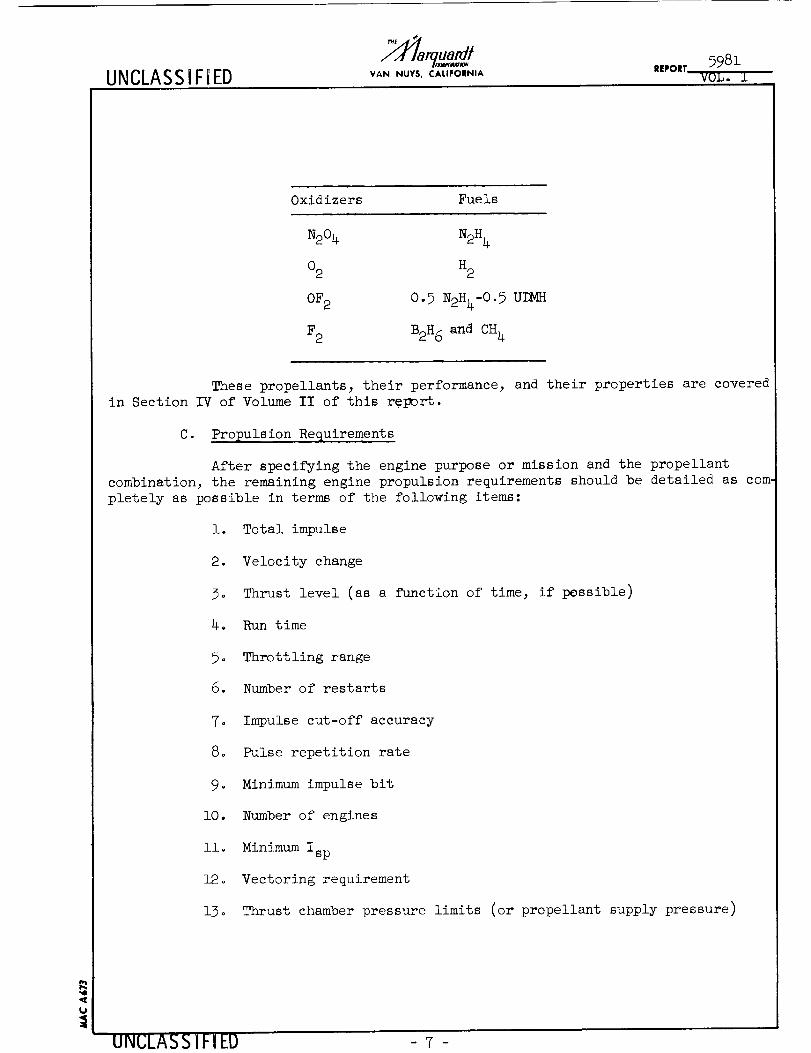
Oxidizers Fuels
N204 N2H 4
02 H2
OF 2 0.5 N2H4-0.5 UEMH
F2 B2_6 B_ cH4
These propellants, their performance, and their properties are covered
in Section IV of Volume II of this report.
C. Propulsion Requirements
After specifying the engine purpose or mission and the propellant
combination, the remaining engine propulsion requirements should be detailed as com.
pletely as possible in terms of the following items:
1. Total impulse
2. Velocity change
3o Thrust level (as a function of time, if pessible)
4. Run time
5o Throttling range
6. Number of restarts
7° Impulse cut-off accuracy
8. Pulse repetition rate
9° Minimum impulse bit
i0. Number of engines
iio Minimum Isp
12o Vectoring requirement
13o Thrust chamber pressure limits (or propellant supply pressure)
UNCLASS IFI ED -7-
UNCLASSIFIED VAN NUYSo CALIFORNIA REPORT 5981VOL, I
Do Environmental and Operational Requirements
As many as possible of the following engine and spacecraft character-istics should also be specified with respect to their effect on the thrust chamberdesign:
i. Engine location with respect to the spacecraft structure
2. Engine envelope limitations
3. Engine configuration (C-D or plug nozzle, contraction ratio,L*, expansion ratio, etc.)
4o Exterior temperature limits or heat loss limits
5. Oxidizer/fuel ratio
6. Storage time in space
7o Distance and attitude of spacecraft with respect to the Sun
8° Maximum acceleration and vibration loads
9o On-board nuclear emission
i0. Re-entry environment
iio Reliability requirements
12. GroUnd check-out requirements
UNCLA35 IFIEU -8-
UNCLASS IFIEDVAN NUY$, CALIFORNIA IIEPOIII 5981
VL).L,,I
V. GENERAL APPLICABILITY CHARACTERISTICS OF
THRUST CHAMBER COOLING METHODS
Certain of the propulsion system requirements specified in the fore-
going section directly affect cooling and may strongly favor one or more cooling
methods while wholly eliminating others. Also_ the severity of the cooling require-
ment will vary over a wide range from inside the combustion chamber, through the
exit nozzle throat, and along the exit cone or skirt. Hence, the optimum thrust
chamber design may well incorporate two or more basic cooling methods, either com-
bined or applied separately to the different chamber components.
A preliminary screening to determine applicable cooling techniques may
be accomplished by consideration first of some of the more critical propulsion re-
quirements and their effect on cooling techniques as pointed out below. A screen-
ing chart summarizing these general design factors is presented in Figure 3- The
screening chart shows, for each cooling method, whether or not an operating require.
ment or range of application may be a limiting factor. A more detailed discussion
of these factors is presented in the text of this section, first in terms of the
propulsion requirement, then in terms of the limitations on each cooling method.
From these initial screening steps, one or several thrust chamber de-
sign approaches may appear promising. A preliminary layout of these designs along
the lines shown in Figure 4 will permit a weight study to be made as outlined in
Section VI.
A. Cooling Techniques Applicable to Particular Propulsion Requirements
i. Propellant Selection
Cooling techniques applicable to the different classes of propel-
lants such as the earth storable hypergolics, the cryogenics with hydrogen as fuel,
and the space storable combinations with the 0F 2 as oxidizer, are presented in
Table IIo The relative severity of the cooling problem is indicated in the table
by the flame temperature, the principle exhaust products, and the regenerative
cooling capability of the propellants.
The applicability envelope for regenerative cooling of four pro-
pellant combinations is presented in Figure 5 _s a function of chamber pressure and
thrust level.
For the earth storable propellants in the chamber pressure range
below 250 psi, the choice of cooling techniques applicable, includes regenerative,
radiative and ablative cooling. Also, for short run times, the use of a heat sink
design is possible. For higher pressures and long run times, film or transpiration
cooling may be required°
UNCLASSIFIED
UNCLASSIFIED
_a
VAN NUYS, CALIFORNIA wot,_ 5981
For the cryogenic propellants using liquid hydrogen as the fuel,
convective cooling is attractive because of the excellent heat transfer properties
of hydrogen. Hydrogen may be used as a regenerative coolant and also as a film or
transpiration coolant. On larger_ engines (lO,O00 pounds thrust and greater) dump
cooling or open tube cooling requiring only a fraction of the hydrogen may be used
effectively in nonregenerative convective cooling. Radiation, ablative, and heat
sink cooling are also applicable so that some optimum combination of these cooling
techniques will probably provide maximum engine performance and flexibility with
minimum complexity.
For the space storable propellants using the OF 2 oxidizer, thehigh flame temperature and the oxygen containing exhaust products provide the
severest of material environments. The flame temperature exceeds the melting tem-
peratures of the most refractory of the metals and carbides. Radiation cooling
would be applicable to the combustion chamber only at very low chamber pressures
or in the exit nozzle skirt at large expansion ratios. None of the propellants in
this group are suitable for convective cooling. Ablative materials would be suit-
able in the combustion chamber and exit skirt for limited run times. In the noz-
:zle throat region, the heat sink concept using a material such as pyrolytic graph-
ite or impregnated porous tungsten is the most suitable for limited run times. For
longer run times, film and transpiration cooling would be applicable with a suit-
able coolant. The capabilities of these propellants for this application have not
been evaluated. Some auxiliary inert coolant may be required for some applications
2. Pulsin_ Requirement
If rapid on and off cycling of the engine is required, passive
protective techniques are best. Starting and stopping of coolant flow is likely
to limit response time or cause excessive coolant waste in a film cooled engine in
addition to giving rise to residual thrust from excess coolant exhaust.
Applicable Coolin_ Techniques
Radiative
Heat sink (Inert)
Ablative (Some residual thrust)
3- Lon$ Rtmi_Ime
Long run time implies a high propellant to hardware weight ratio.
Minimum performance penalty is important.
Applicable Coolin$ TechniQues
Regenerative
Radiative
Ablative (Weight increases as [run time] 1/2)
Open tube (Some performance penalty)
UNCLASSIFIED - lO -

UNCLASSIFIED5981
VAN NUY5, CALIFORNIA IIEPORT VOL. I
4o Throttling
The cooling requirement for throttling operations varies with
chamber pressure as thrust is varied.
Applicable Coolin_ Techniques
Radiative
Ablative (Char rate almost independent of thrust)
Regenerative (Range of throttling limited)
Open tube (Coolant can be separately controlled)
Heat sink (Time limited)
Film cooling (May incur increased Isp losses)
Transpiration cooling (May incur increased I losses)sp
5- Fast Response
Accurate impulse control requires fast response of cooling tech-
nique and absence of residual thrust.
Applicable Cooling Techniques
Radiative
Heat sink
Ablative (Some residual thrust)
6o Limited Engine Envelope
-: For required total impulse or velocity change, the engine size
may be reduced by employing a lower thrust engine for a longer time, by using a
limited expansion ratio, or by employing higher chamber pressures.
Applicable Cooling Techniques
Regenerative
Open tube
Film
Transpiration
Ablative (Throat may impose pressure or time limit)
UNCLASS IFIED ll -
UNCLASSIFIED YAH NUY$, CALIFOINIA m5981
VOJJ. i
Bo Applicability of Specific Cooling Techniques
io Regenerative Coolin_
a° Cooling Limitations
Three specific factors have been utilized to describe limita-
tions on regenerative cooling of rocket thrust chambers. These are a coolant sup-
ply pressure requirement, a minimum practical passage dimension, and a maximum
coolant temperature rise. The coolant temperature limitation is expressed either
as a maximum nozzle expansion ratio which can be cooled, or in the case of hydrogen
cooling, as a percentage of a maximum allowable enthalpy rise.
Methods by which these limits are derived and correlated with
thrust and chamber pressure are explained in Volume II. Boundaries of the feasi-
bility map for regenerative cooling with the propellant combinations of N204/N_H4,
02/H2, F2/H2, and N204/Aerozine 50 are presented in Figure 5- Reasonable cooling
solutions are possible within these envelopes.
Further increases in chamber pressure over those shown in
Figure 5 may be accommodated by resorting to supplementary methods such as film
cooling, ceramic coatings, etc.
Nozzle wall temperatures, while not specifically expressed in
any of the limiting envelopes, are nevertheless inherent in them. For the class of
liquid coolants transferring heat by nucleate boiling, the chamber _ll operating
temperature is a fixed function of the coolant pressure. In the convective cooling
situation, using hydrogen, all points in the grid were computed for a 2000°R wall
surface temperature. This represents a realistic level for currently developed
rocket engine construction materials.
b. 0_erational Limitations
Several factors are apparent that, while not directly limiting
or excluding regenerative cooling, should be considered in the process of selecting
a cooling method° In general, conclusions about these parameters can be made only
after making complex tradeoff studies between engine weight, volume, design sim-
plicity, reliability, etco
(i). Restart
The regenerative cooling concept imposes no limitations
upon restart of rocket engines other than added complexity to sequencing.
!
UNCLASSIFIED - 12-
UNCLASSIFIED_a O_/ 59 81
VAN NUYS, CALIFOIH41A ILqDOaTV U.L,. I
(2). Pulse Operation (Response Time)
Starting and stopping operations exhibit poor response
if there is no valve between the coolant passages and injectors. While regenera-
tive cooling should be able to satisfy "_V engine" requirements, attitude Control
or "station keeping" would seem too exacting.
(3). S_ace Storage (Purging)
In general, the volume of a liquid cooling jacket should
be gas purged after each operating cycle. Some of the reasons for this are as fol-
lows:
i. Slow draining of Jacket by evaporation of
liquid coolants
2. Possible sporadic ignition of hypergolic
propellants
3. Possible freezing of coolant in a space
environment and blocking flow passages
(4). Throttlin_
Specific problems of throttling regenerative cooled
engines are discussed in Volume II. Graphs illustrating throttling capabilities
and statements concerning design concepts are presented. In general, the throttlin_
ratio is limited and imposes restrictions on the regenerative cooling envelope of
applicability.
(5)- Pro_ellant Chgice
Hydrogen is the best coolant, followed by N2H 4 andAerozine 50 in that order. Not much is known concerning the capabilities of
diborane. Pentaborane, however, has only limited cooling potential.
(6). Zero g
regenerative cooling.
A weightless state should cause no important effects in
(7). Meteoroids
It is difficult to estimate the effect of a penetration
of the cooling jacket by a meteoroid. Regenerative cooled chambers have been known
to operate_ without catastrophic results_ with as much as i0 percent of the coolant
passages containing holes. External leaks, in the atmosphere, can be quite serious
Whether they would represent anything other than a performance loss in space re-
mains to be determined.
UNCLASSIFIED - 13-
UNCLASSIFIED__ 5981
VAN NUYS. CALIFOI_IA IIIPOIIT,,VU.b. ±
B II
(8). Exterior Wall Temperature
Exterior wall temperatures would approach coolant tem-
perature_ less than 400°F for storable liquid fuels and temperatures above IO00°F
for hydrogen.
2. Open Tube ,(Du.m_ Cooling)
a. Coolin6 Limitations
Dump cooling is an attempt to make use of the excellent heat
transfer characteristics of high temperature gaseous hydrogen. The object is to
cool the chamber walls convectively with a very small percentage of the total hy-
drogen flow thereby eliminating the coolant jacket pressure drop in the main pro-
pellant flow. Since the majority of fuel never passes through the cooling jacket
and that which does, is dumped to space at the nozzle exit, the maximum pressure
to which the fuel need be raised is the injection pressure. This reduction in
fuel pressurization represents the major advantage of the dump cooling concept.
It is of course obvious that a chamber that cannot be cooled
with the total fuel flow by regenerative methods, cannot be cooled by a fraction
of the fuel by dump procedures° Therefore, dump cooling is limited to those areas
wherein regenerative cooling is relatively easy. In these regions of high thrust
or low chamber pressure, the hydrogen coolant capacity heat is limited due to the
coolant temperature approaching the maximum structural temperature.
Primary among the penalties involved in the dump cooling de-
sign, is the increase in hydrogen required. Most investigators report dump cooled
designs using around 2% of the total propellant flow rate. At the normal 02/H 2
mixture ratio of 5:1, however, this represents a 12% increase in hydrogen. With
the very low storage density (from 4.5 to 5.0 pcf) for hydrogen, this can represent
a significant amount of tank volume for large thrust chambers of long duration. To
help counteract this penalty, the dump flow may be expanded to produce useful
t_ust at a level of Isp slightly greater than that of the thrust chamber. The netperformance effect is small and a system analysis would be required for completeevaluation.
In summation, there appears to be at least two potential uses
for dump cooling of large thrust engines. The first is where the saving of fuel
pressurization overcomes the increased tankage volume. The second is for short
duration, pulse operation at pressures in excess of radiation cooling limits, where
soak back and duty cycle considerations in ablative chambers would result in
chamber weights greater than those for dump cooling. The weights of dump cooled
chambers are taken to be the same as those for regeneratively cooled chambers.
U S IFIED - 14 -

UNCLASS IFIED
tube cooling.
b, Operational Limitations
(i). Restart
There are no limitations in restart operations with open
(2). Response Time
Open tube cooling has much faster response than re-
generative cooling due to the reduced mass of the coolant.
(3). Space Storase (Purging)
The necessity for purging seems unlikely with open tube
cooling due to the low mass of coolant, simple flow path, and the independent
nature of the coolant jacket and injector.
(4). Throttling
Since coolant flow can be regulated independently, open
tube cooling seems ideal for throttling.
(5). Propellant Choice
Open tube cooling is limited to gaseous coolants that
are stable at high temperatures, i.e., hydrogen.
(6). Meteoroids
Penetrations in the expansion nozzle could result in
askew thrust vect6rs. Otherwise, the situation would be similar to that for re-
generative cooling with considerably less performance penalty.
(7)- Thrust Levels
Open tube cooling generally is applicable only to large
thrust engines (> lO,O00 lbf).
3- Radiation Cooling
a. Coolin5 Limitations
The characteristic limitation on radiation cooling is the
availability of materials which can operate at the equilibrium thrust chamber wall
temperatures reached during steady state operation. These temperatures are most
sensitive to chamber pressure and nozzle area ratio. Typical predicted equilibrium
wall temperature distributions as a function of chamber pressure and nozzle area
are shown for one propellant combination in Figure 6. Of particular interest, is
the application of radiation cooling to the expansion nozzle skirt at large area
UNCLASSIFIED - 15 -
UNCLASSIFIED/Z_8_ 5981
VAN NUY$, CALIFOINIAVL)_. .I.
ratios° Due to the reduced heat fluxes, low static gas pressures, and large sur-
face areas involved, radiation cooling can be employed to gain increased engine
thrust at small increases in structural weight. Radiation cooled chambers of
thrust levels less than 100 pounds have been developed to run under steady state
conditions for over an hour at chamber pressures of 90 psia. Experimental heat
transfer rates in small thrust chambers can be controlled by injector design to
permit chamber pressures well above theoretical limits.
The most important limit on firing duration is the life of the
protective coatings used on refractory metals. Actual thrust chamber lives of
several hours have been demonstrated with molybdenum disilicide at metal tempera-
tures above 3000°F. The silicide coatings of other refractory metals are probably
comparable, based on test samples in oxyacetylene and plasma flames. Data on time-
temperature capabilities of coated refractory metals are presented in Figure 152
of Volume IIo Very thin wall chambers might also have a duration limit due to
creep.
Figure 7 presents a typical plot of limiting chamber pressure
versus engine thrust based on a limiting throat wall temperature of 3300°F as cal-
culated from normal heat transfer methods (Reference 2). The experimental point
indicates the operating pressure of a 100 pound thrust radiation cooled molybdenum
chamber with an L* of less than 15 inches. The typical throat wall temperatures
for this thrust chamber are less than 3000°F.
The propellants establish very important limits of applicabil-
ity, which depend on the compatibility of the combustion gas with the motor walls
or coatings and the combustion gas temperature. Most of the propellant combina-
tions considered contain water vapor as the most reactive gas, but F2/H 2 and
OF2/B2H 6 products are primarily HF, H2, or other unusual species, many of which
have not been completely evaluated as to their reactions with bare refractory
metals and graphite. Since HF is not highly reactive with tungsten nor with graph-
ite, a radiation cooled motor of bare tungsten or pyrolytic graphite is probably
feasible for F2/H 2 at some chamber pressures and mixture ratios. Thrust chamber
materials and coatings for use with 0F2/B2H 6 are not known at present.
b. O_erational Limitations
(I)° Space Vacuum
One hazard to operation in space is the possible evapora-
tion of the protective coating when the hot motor is exposed to vacuum. This has
not been found to be a serious problem for molybdenum disilicide, but the behavior
of other coatings in a vacuum is not known.
(2). Earth Re-Entry
A radiation cooled thrust chamber can be operated during
earth re-entry if it is situated so that its walls do not exceed the maximum coat-
ing temperature° A buried installation is also possible, using a cooled or heatsink radiation shield between the motor and the vehicle.
UNCLASSIFIED - 1G-
UNCLASSIFIED/T_a_ ,p_. 5981
VAN NLrY$.CALOFOleaOA VOL. I
(3). Clustered Engines
Although radiation between clustered motors exists, the
amountof resultant overheating of the motor will not be great unless the motors
are arranged so that the combustion chambers or throats are very close. Close
proximity of the expansion nozzles is not a problem because they are well below the
limiting coating temperature.
(4). Heat Transfer to Vehicle
Radiation cooled motors may be required to operate in
the vicinity of a portion of the vehicle which should absorb only a limited amount
of radiant heat from the motor. Radiation shields, combined with high thermal con-
ductivity heat sinks or insulators can reflect the radiation to space unless the
motor is so completely surrounded by the vehicle that a separately cooled radiation
shield is required.
(5)- Advanced Nozzle T_pes
Radiation cooling of other motor configurations than a
convergent-divergent nozzle would be seriously limited because almost all other
configurations use a plug or similar structure to form the throat, and the shape
factor for radiation to space from the plug throat is quite small. Some portions
of these configurations could be radiation cooled, however.
(6). Meteoroids
Meteoroid penetration of thin coatings on refractory
metals is a possibility. Erosion or penetration of the coating on exterior sur-
faces exposed only to space vacuum is not critical and the penetration of the in-
terior chamber surface has a much reduced probability. Radiation cooled exit
skirts of coated molybdenum have been run successfully for complete duty cycles
with holes purposely drilled through the metal wall and coating.
4. Ablative Coolin_
a. Cooling Limitations
For liquid engine application, the oriented silica fiber rein-
forced phenolics have consistently shown superior performance over other ablative
materials as combustion chamber liners. This has been attributed to the very
viscous molten silica film which forms on the charred surface during operation.
As a throat material, silica reinforced phenolics have shown
considerable promise for the earth storable propellants at pressures up to 150 psia
and throat diameters of 1 inch and larger. Actual throat erosion rates are sensi-
tive to run time and propellant injector performance.
!
UNCLASSIFIED - 17-
UNCLASSIFIED YA#I NIYI, C.AIIFOIII_IIA5981
VOL. I
For a typical application, the char depth and hence the re-
quired thrust chamber wall thickness increases with burning time to the one-half
power as shown by the experimental data in Figure 8. Char rates for transient
ablation and for a non-receding or non-eroding liner surface are not very sensitive
to flame temperature or chamber pressure. However, surface erosion at the nozzle
throat and at high velocity flow conditions limits run times with the cryogenic and
space storable high energy propellants.
b. Operational Limitations
(i). Restart Capability
There do not appear to be any limitations on the restart
capability of properly designed ablative chambers, either in a vacuum or at sea
level. The only limitation appears to be that if the chamber is restarted before
it is allowed to cool completely, a weight penalty will be imposed in terms of addi-
tional char thickness required. It has been previously postulated, and verified
experimentally, that for long off times, the additional charring that takes place
on shutdown is offset by the time delay before charring proceeds on the succeeding
run due to the greater refractory barrier imposed by the thickened char structure.
The added char depth due to postrun charring has not been completely evaluated.
(2). Short Pulse Operation Capability
There are no apparent limitations to short pulse opera-
tion except for the weight penalties imposed by excessive charring under this typeof operation. The considerations are similar to those mentioned under restart ex-
cept that the material is never allowed to cool below its char temperature during
the cycling period and the char continues at the same rate during the "off" condi-
tion. Under Marquardt testing this has doubled the char for a short pulse (50%
duty cycle) over that which would have been sustained for a steady state firing of
the same accumulated firing duration. The magnitude of this factor would vary with
the pulse width, "on" time versus "off" time (percent duty cycle) and "off" time
between series of cycling bursts. Residual thrust due to postrun charring of rein-
forced phenolic is shown in Figure 9 for the case of a 1/16 inch char and resultant
gas release.
(3). Throttling Capabilities
There are no detrimental effects in the throttling of
ablative engines except as it affects the efficiency of the ablative process. As
the chamber pressure is throttled to a lower value, the lower efficiency of the
ablative process at the lower heat flux (due to incomplete cracking of gaseous
pyrolysis products) causes the char to proceed at about the same rate.
(4). Storage Limits
There are some storage effects with all resin systems
since they all degrade to a degree in time when exposed to temperatures well below
their char temperature. Presently considered phenolic systems have been the most
widely evaluated under heat, vacuum, and ultraviolet radiation. It is estimated
that about 10% of a phenolic will volatize in one year at 500°F under a hard
vacuum°
UNCLASSIFIED - 18-

UNCLASSIFIED WU,I HI,/Y|, CALIFOINIA5781
VOL. I
(5). High g O_eration
Little information is available on high g effect. How-
ever, it could be detrimental in displacing a molten reinforcement at the ablating
surface especially, if the chamber is shut down under the application of a large
g force.
(6). Meteoroids
The effects of meteoroid penetration on reinforced
phenolics are not predictable at present° The thicker walls would appear to give
greater resistance to penetration than the thin tubing or coated refractories.
(7). S_ace Radiation
Phenolic resin systems and others are adequately stable
under space levels of radiation.
(8). Outside Wall Temperatures
The structural requirements of reinforced phenolics
permit operation at exterior wall temperatures between 50_ and 800°F without extra
insulation.
5. Film Cooling
In film cooling_ the fluid is introduced directly into the thrust
chamber° This layer of fluid or gas then absorbs heat and thickens the effective
boundary layer and reduces the heat flux to the thrust chamber surfaces.
Cooling films may be generated in several ways as follows:
i. Liquid fuel or oxidizer injected through wall slots or holesin the combustion chamber ahead of the critical nozzle area
2. Separate injection of propellant along the chamber walls from
the propellant injector
3. Design of the injector to provide a fuel-rich, reacted gas
mixture along the chamber walls
4. Evaporative heat sink of coolant discharging into the coma
bustion chamber
UNCLASSIFIED 19 -
UNCLASSIFIED VAN NUY$, CALIFOIINIA N
Film cooling may be used effectively to protect the chamber walls
in several ways as follows:
i. Reduction of the "adiabatic" wall temperature to a value
below the material limiting temperature
2. A reduction in the heat flux to a wall which is also
cooled by radiation, convection, or a heat sink
. Maintaining a non-oxidizing gas adjacent to refractory
surfaces Otherwise capable of withstanding full combustion
gas temperature, such as uncoated tungsten, tantalum, orvarious carbides
a. Cooling Limitations
There are no apparent limitations on cooling capability, time,
or chamber pressure with either film or transpiration cooling. If one of the pro-
pellants (usually the fuel) or an inert fluid is used as a coolant at the nozzle
throat, there is a performance penalty (Isp loss) due to gas and temperature strati-fication. Figure i0 indicates that a typical performance loss due to film cooling
is proportional to the quantity of coolant flow.
b. Operational Limitations
Pulsing and multiple starts may result in coolant waste due to
a requirement to establish coolant flow prior to ignition and also from residual
flow from coolant passages after shutdown. Plugging of cooling passages or tran-
spiration media may be caused by thermal decomposition of coolant under cyclingconditions.
6. Transpiration Cooling
Transpiration cooling may be thought of as a special case of film
cooling and many of the same design considerations apply. The transpiration effect
may be produced in several ways including the following:
i. Fuel forced through a porous wall
2. Water or other coolant delivered from a reservoir and
pumped through a porous surface
A porous refractory slab filled with copper, lithium,
subliming salts, etc., which are vaporized and discharged
into the thrust chamber
This form of cooling is most applicable to one-shot, constant
thrust engines due to the problems of flow control and shutdown effects.
UNCLASS IFIED 2o -

UNCLASSIFIED VAN HUY$, CALIFOINIAN
5981
VQL. I
7. Heat Sink Cooling
a. Coolin_ Limitations
Combustion chamber component temperatures may be held below
structural limits while heat is being conducted away from the surface and absorbed
in the chamber walls° The primary limitation on this concept is the run time
available before a limiting surface temperature is reaced. Two limiting tempera-
tures are encountered: First, the melting, subliming, or softening temperature at
which the material would flow or erode rapidly, and second, the temperature at
which the oxidation rate or reaction rate with the combustion gases would be ex-
cessiveo
Promising heat sink materials are those which have high heat
capacity, high thermal conductivity, high structural temperature limits, and com-
patibility with combustion gases. Pyrolytic graphite, isotropic graphite, and
tungsten top the list for use with high temperature propellants. Oxidation is the
critical problem with combustion gases containing C02 and H20. Graphite and
tungsten surface coatings offer only a partial solution to this problem, since
available coatings are limited to temperatures of less than 4000°F.
Surface temperature rise rates for isotropic and pyrolytic
graphite in a combustion environment are shown in Figures ll and 12. Temperatures
of an i_sulated pyrolytic graphite insert in a 4 inch diameter nozzle throat, would
be less than 3000°F for 200 seconds at 150 psia chamber pressure and 5000°F gas
temperature. However, at more severe conditions such as 300 psia and 7000°F gas
temperature, the 3000°F surface temperature would be reached in lO seconds.
Theoretically, the run times for heat sink nozzles can be ex-
tended through the use of endothermic heat sink materials. These are materials
such as subliming salts, lithium compounds, and low melting point metals capable
of absorbing large amounts of heat through a phase change from an initial solid
state. The endothermic materials may be impregnated into porous refractory wall
materials or used to back up the walls as an insulator as well as a heat sink°
b. Operational Limitations
(i) o Pulsing Operation
Inert heat sinks are best suited to low duty cycle
pulsing operation. Indefinite run times can be achieved with limited radiation
cooling. Endothermic heat sinks would not be applicable.
(2). Throttling
No limitation except total run time° Throttled opera-
tion increases available run time°
meteoroid damage°
(3)° Meteoroids
Heavy walled sections provide minimum effects due to
UNCLASS IFIED - 2l -
UNCLASSIFIED VAN NUY$, CALIFOI_IIA u 5981
VOL. I.
(4). Exterior Wall Temperatures
The structural limits of heat sink materials may permit
operation at exterior wall temperatures above 4000°F. If environmental require-
ments do not permit this, available insulations can be used to reduce the exterior
temperatures to less than 300°F and a minimum heat flux with some weight increase.
UNCLASSIFIED - 22 -
UNCLASSIFIED VAN NUY$o CALIFODIIAII_OtT
5981
VU_. i
VI. PRELIMINARY THRUST CHAMBER WEIGHT ANALYSES
Selection of a cooling method from several which are applicable over
the same required range of operating conditions may be made on the basis of thrust
chamber weight. This section presents typical component weights for different
cooling methods to facilitate this weight comparison. Injector and attachment
flange weights are not included in this section.
A. Typical Thrust Chamber Configurations
The typical thrust chamber configuration lines used in these compari-
sons are shown in Figure 4 for a 40 to 1 exit nozzle expansion ratio. Combustion
chamber contraction ratios (Ac/A.) vary for different applications but in general
they decrease at higher thrust levels whereas the ratio of thrust chamber volume
to nozzle throat area (defined as L*) increases with thrust. For the purpose of
making a weight comparison study, nominal values of contraction ratio are assumed
to be between 4 and 2, and L* is assumed to vary as shown in Figure 13.
Nozzle thrust coefficient (CF) varies with propellant, chamber pres-
sure, and expansion ratio. But to provide a basis for weight comparison, a fixed
value of 1o89 is assumed based on Ae/A. = 40. The variation with propellant and
expansion ratio is shown in Figure 14. For an evaluation of the effect of varying
nozzle expansion ratio on weight and performance, CF may be varied accordingly°
Figure 15 presents a plot of engine throat diameter versus chamber pressure and
thrust for use in the weight study based on the equation
F = c
The exit nozzle contour is assumed similar to the Rao contour with a
length from the nozzle throat to the exit plane equal to 7_ of the length of the
equivalent 15 ° divergent cone. This length may be expressed by the equation
1/2
Ln = 1.35D* F_Ae _ - 1
which is plotted in Figure 16.
Thrust chamber and nozzle surface areas as a function of throat
diameter contraction and expansion ratio are given in Figures 17 and 18.
Fairly detailed typical weight data are presented for regenerative,
radiation, and ablatively cooled thrust chambers. For the purposes of a preliminar
weight analysis, it may be postulated that the structural weights of dump cooled
(open tube), film cooled, and transpiration cooled structures are the same as the
weights of the regeneratively cooled thrust chamber. It is also postulated that
the heat sink thrust chambers are equal in weight to the ablative thrust chambers o
For the limited number of cases evaluated, these assumptions proved adequate, the
choice would not be based primarily on a chamber weight comparison, especially for
these latter cooling methods.
UNCLASSIFIED - 23 -
UNCLA$ ;IFIED/T_a_ 5981
VAN NUY$, CALIFOIINIA II_VUJJ. J.
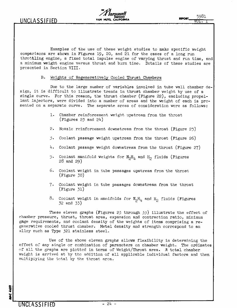
Examples of the use of these weight studies to make specific weight
comparisons are shown in Figures 19, 20, and 21 for the cases of a long run
throttling engine, a fixed total impulse engine of varying thrust and run time, and
a minimum weight engine versus thrust and burn time. Details of these studies are
presented in Section VIII.
B. Wei6hts of Regenerativel_ Cooled Thrust Chambers
Due to the large number of variables involved in tube wall chamber de-
sign, it is difficult to illustrate trends in thrust chamber weight by use of a
single curve. For this reason, the thrust chamber (Figure 22), excluding propel-
lant injectors, were divided into a number of areas and the weight of each is pre-
sented on a separate curve. The separate areas of consideration were as follows:
1. Chamber reinforcement weight upstream from the throat
(Figures 23 and 24)
2. Nozzle reinforcement downstream from the throat (Figure 25)
3. Coolant passage weight upstream from the throat (Figure 26)
4. Coolant passage weight downstream from the throat (Figure 27)
5. Coolant manifold weights for N2H 4 and H2 fluids (Figures28 and 29)
6. Coolant weight in tube passages upstream from the throat
(Figure 30)
7. Coolant weight in tube passages downstream from the throat
(Figure 31)
8. Coolant weight in manifolds for N2H 4 and H2 fluids (Figures32 and 33)
These eleven graphs (Figures 23 through 33) illustrate the effect of
chamber pressure, thrust, throat area, expansion and contraction ratio, minimum
gage requirements, and coolant density of the weights of items comprising a re-
generative cooled thrust chamber. Metal density and strength correspond to an
alloy such as Type 321 stainless steel.
Use of the above eleven graphs allows flexibility in determining the
effect of any single or combination of parameters on chamber weight. The ordinates
of all the graphs are plotted in terms of Weight/Throat area. A total chamber
weight is arrived at by the addition of all applicable individual factors and then
multiplying the total by the throat area.
UNCLASSIFIED 24 -

UNCLASS IFIED VAIl NUY$,CALIIIOINIAIIEI'OII" 5981
VUL. I
Predicted weights for several thrust chambers of different chamber
pressure, expansion ratio, and throat area are given in Figure 34 for the 02/H 2
propellant combination. This is representative of the more specific types of
results that can be obtained from the set of weight curves.
Weight information as presented in and determined from the graphs in
this section is not intended to represent the shelf weight of regeneratively cooled
thrust chambers, since actual delivery weight is a strong function of specific de-
tails of size and application. However, the accuracy of the curves should be with-
in i0 to 15 percent.
C. Weights of Radiation Cooled Thrust Chambers
The weights of radiation cooled motors of the configuration shown in
Figures 35 and 36 were based on the following assumptions:
i. Motor wall temperatures for the propellant system
N204/0. 5 N2H4-O. 5 UDMHwith 95 percent C* efficiency
2. Wall emissivity factor = 0.72
3. Effective shape factor = 1.0 in combustion chamber
4. Material selection above 2000°F: 90_ tantalum-lO_ tungsten
using tensile strength for 1 percent creep in lO minutes
5. Material selection below 2000°F: Haynes 25 alloy using
tensile strength for 0.2 percent yield
6. Minimum wall thickness in all cases = 0.020 inch
The weight of radiation cooled motors using 90% tantalum-10% tungsten
throughout is shown in Figure 35. The weight of motors using 90 Ta - 10W in the
chamber and throat and Haynes 25 alloy in the expansion nozzle where metal tempera-
tures are below 2000°F is shown in Figure 36. The maximum wall temperature for
many of the combinations of chamber pressure and thrust indicated in Figures 35 and
36 exceeds the 3300°F limit of coatings currently available, and hence are not
feasible from an oxidation standpoint. Chamber weights for 02/H 2 propellants would
be approximately equal to those shown here with the same limit on coating tempera-
tureso
Weight estimations for radiation cooled expansion skirts for area
ratios greater than 40:1 are facilitated by the curve of nozzle surface areas
plotted in Figure 18. The areas shown are exact for a nozzle contoured for a
40_1 area ratio, but are approximate for alternate expansions.
UNCLASSIFIED - 25 -
UNCLASS IFIED VAN NUY$, CALIFOINIA
!
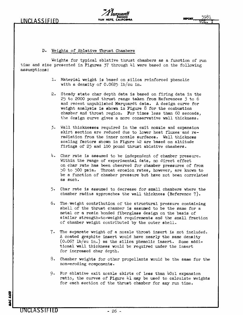
D. Wei6hts of Ablative Thrust Chambers
Weights for typical ablative thrust chambers as a function of run
time and size presented in Figures 37 through 41 were based on the following
assumptions:
i. Material weight is based on silica reinforced phenolic
with a density of 0.0625 lb/cu in.
o
.
.
Steady state char depth data is based on firing data in the
25 to 2000 pound thrust range taken from References 3 to 6
and recent unpublished Marquardt data. A design curve for
weight analysis is shown in Figure 8 for the combustion
chamber and throat region. For times less than 60 seconds,
the design curve gives a more conservative wall thickness.
Wall thicknesses required in the exit nozzle and expansion
skirt section are reduced due to lower heat fluxes and re-
radiation from the inner nozzle surfaces. Wall thickness
scaling factors shown in Figure 42 are based on altitude
firings of 25 and 100 pound thrust ablative chambers.
Char rate is assumed to be independent of chamber pressure.
Within the range of experimental data, no direct effect
on char rate has been observed for chamber pressures of from
50 to 500 psia. Throat erosion rates, however, are known to
be a function of chamber pressure but have not been correlatedas such.
.
o
Char rate is assumed to decrease for small chambers where the
chamber radius approaches the wall thickness (Reference 7)-
Theweight contribution of the structural pressure containingshell of the thrust chamber is assumed to be the same for a
metal or a resin bonded fiberglass design on the basis of
similar strength-to-weight requirements and the small fraction
of chamber weight contributed by the outer shell.
.
.
The separate weight of a nozzle throat insert is not included.
A coated graphite insert would have nearly the same density
(0.067 lb/cu in.) as the silica phenolic insert. Some addi-
tional wall thickness would be required under the insert
for increased char depth.
Chamber weights for other propellants would be the same for the
non-eroding components.
. For ablative exit nozzle skirts of less than 40:i expansion
ratio, the curves of Figure 41 may be used to calculate weights
for each section of the thrust chamber for any run time.
UNCLASS IFIED 26 -

UNCLASSIFIED VAN NUVS,CA.FO_IA ¥OL. I
VII. PROPULSION PERFORMANCE PENALTIES
A. Isp Losses Due to Film and Transpiration Cooling
If a film of liquid or gas flows through a rocket nozzle throat at a
temperature different than that of the main bulk of exhaust gas, the net thrust
of the engine will be less than that which would result if the gases had been
thoroughly mixed with the same overall total enthalpy. This gas stratification
effect is independent of the effective chemical combustion efficiency. The
analytical evaluation of this phenomena is presented in Appendix B of Volume II.
The magnitude of this effect on Isp is presented for various film temperatures
and film thicknesses in Figure 43.
An additional Isp loss may be incurred due to the operation at pro-
pellant mixture ratios other than optimum in order to insure sufficient propellant
as film coolant. Ideally, for a _ hydrogen film coolant flow, this loss could be
less than l_. The stratification loss could vary from 2 to % depending upon the
effective film temperature.
Experimental data as shown in Figure i0 (from Reference 8) confirm
a performance loss approximately equal to the percentage of coolant flow. For
preliminary design, this is the recommended value to use.
There is some recent experimental evidence that Isp losses may be in-
curred with an ablative thrust chamber due to the transpiration effect of the
ablative material. However, no numbers are available to evaluate the separate ef-
fects of shear force losses, changes in contour, or throat erosion as well as the
transpiration film effect. A typical gas generation rate from the thermal degrada-tion of an ablative liner at normal char rates is less than 1/lO of 1 percent of
the propellant flow, so that this should be a negligible loss.
B. Thrust and Isp Changes Due to Throat Erosion
Nozzle throat erosion, if controlled and predictable, could be ac-
ceptable in some engine applications. The effect on thrust, propellant flow rate,
and Isp have been calculated for throat enlargements up to 2%. For fixed areapropellant injectors and fixed propellant supply pressure, engine thrust would in-
crease while decreasing in Iso performance. An Isp loss of only 0._ would be in-
curred for as much as lO_ increase in throat area. This effect is shown in Figure
44 as a function of throat area increase and propellant injection pressure ratio
for a 40:1 expansion thrust chamber. The further assumption has been made that
there are no aerodynamic losses due to distortions in the nozzle contour.
C. Heat Losses and Pressure Losses
Heat losses from combustion gases to thrust chamber walls and the
pumping energy required to overcome pressure losses in propellant and coolant liner
result in a loss in impulse efficiency (Isp loss) equal to one-half of the ratio ofthe energy loss to the total gas nthalpy° The theoretical relationships are
worked out in Appendix B to Volume II of this report.
UNCLAS SIFIED 27 -

UNCLASSIFIED vAN NUY$, CALIIIOINIA
5981
VU_, I
In a typical 2000 pound thrust radiation cooled engine, the total heat
flux lost through the combustion chamber walls would be 72 Btu/se_. This is ap-
proximately 0.6% of the total gas flow enthalpy. Hence, the I loss due to heat
transfer would be 0.3_. sp
D. Residual Thrust in Ablative Engi_nes
After an ablative thrust chamber has been running for several seconds
and stopped, the heat stored in the charred phenolic and silica reinforcement must
soak into the virgin material. Thermal degradation of the virgin material will
continue to occur until the mean temperature of the char is reduced to near 500°F.
Postrun charring of 0.062 to 0.25 inch of virgin phenolic may be calculated de-
pending upon the char depth at shut down. However, limited experimental data on
postrun temperatures indicate that a somewhat thinner post char thickness actually
develops.
The weight of gas generated due to charring is approximately 15_ by
weight of the ablative material which is charred. If the gas released during the
postchar period, which may be as long as 100 seconds, is heated in the chamber to
an average of ll00°F, a residual postrun impulse may be calculated, as shown in
Figure 9, as a function of thrust and chamber pressure. The curves show a total
postrun impulse for 0.062 inch char in a lO0 pound thrust engine is 3 lbf-sec.
This is equivalent to a 30 millisecond pulse width which is greater than the de-
sired minimum typical pulse widths shown in Figure 45. However, if pulse firing
were the normal mode of operation, less severe temperature gradients in the walls
would greatly reduce postrun charring.
In Table I (mission requirements), a typical value of large engine
thrust to spacecraft mass is 1.O and a typical value of impulse cutoff accuracy
is 1.0 lbf-sec per pound of spacecraft mass, hence an allowable impulse of 1.0
lbf-sec per lbf of engine thrust may be typical. Values of residual impulse shown
in Figure 9 are all below 0.1 and O.01 lbf-sec per lbf. However, within the
probable ranges of these variables, postrun charring may be a design consideration.
E. 0ptimumExit Nozzle Expansion Ratio Versus En6ine Performance;Weight, and Size
The performance gain in Isp associated with increasing exit nozzleexpansion ratios is attained at the expense of increased exit diameter, increased
nozzle length_ and increased nozzle weight. The attainment is also dependent on
whether the flow achieves frozen or shifting equilibrium.
The potential gain in performance (Is_) for different propellants is
shown in Figure 46 for expansion ratios of from 15_to 800 with shifting equilibrium.
The weight penalty associated with large expansion ratios consists of
i. The weight of nozzle skirt, which may be radiation cooled at
large expansion ratios
2. Increased structure weight associated with increased supportingloads
3. Increased structure weight of surrounding structure due to in-
creased engine diameter and length
UNCLASSIFIED - 28 -

UNCIASSIFIED VAN I_JYS, CALIFOINIA5981
VOL. I
As an alternate concept_ a net performance gain within a fixed engine
envelope and fixed thrust may be possible by using very high chamber pressures with
a very large expansion ratio. The increased severity of the cooling problem may be
approached by the use of film and transpiration cooling. There may be a net gain
if the coolant losses can be minimized and shifting equilibrium performance ap-
proached. An example of this trade-off is given in the following table which con-siders the case of increasing chamber pressure from 50 to I000 psia and Ae/A . from
40 to 800 to provide a constant exit diameter. The greatest potential gain is with
the OF2/B2H6 propellants if the cooling problem can be solved.
Propellant
OF2/H 2
OF2/B2H6
02/H 2
o/F
7.0
4.0
5.0
Max. Isp at 50 psi
Ae/A.= 40
Max. Isp at i000 psi
Ae/A . = 800
473 sec
43O
453
509 see
494
494
Percent
Increase Isp
7.5
15.
9.
UNCLASSIFIED - 29 -
UNCLASSIFIED VAN I_JYS.CALII'OIINIA5981
VOL. I
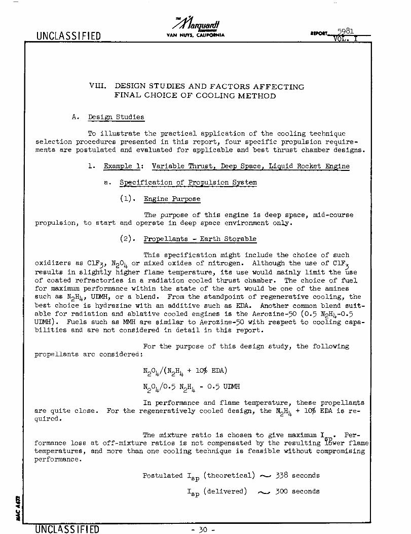
VIII. DESIGN STUDIES AND FACTORS AFFECTING
FINAL CHOICE OF COOLING METHOD
!
A. Design Studies
To illustrate the practical application of the cooling technique
selection procedures presented in this report, four specific propulsion require-
ments are postulated and evaluated for applicable and best thrust chamber designs.
i. Example i: Variable Thrust 2 Deep Space 2 Liquid Rocket En$ine
a. Specification of Propulsion System
(i). Engine Purpose
The purpose of this engine is deep space, mid-course
propulsion, to start and operate in deep space environment only.
(2). Propellants - Earth Storable
This specification might include the choice of such
oxidizers as CIF3, N204 or mixed oxides of nitrogen. Although the use of CIF 3
results in slightly higher flame temperature, its use would mainly limit the useof coated refractories in a radiation cooled thrust chamber. The choice of fuel
for maximum performance within the state of the art would be one of the amines
such as N2H4, UEMH, or a blend. From the standpoint of regenerative cooling, the
best choice is hydrazine with an additive such as EDA. Another common blend suit-
able for radiation and ablative cooled engines is the Aerozine-50 (0.5 N2H4-O.5UDMH). Fuels such as MMH are similar to Aerozine-50 with respect to cooling capa-
bilities and are not considered in detail in this report.
For the purpose of this design study, the following
propellants are considered:
are quite close.
quired.
N204/(NaH 4 * 10% EDA)
N204/0.5 N2H 4 - 0.5 UI_4H
In performance and flame temperature, these propellants
For the regeneratively cooled design, the N2H 4 + i0_ EDA is re-
The mixture ratio is chosen to give maximum I. • Per-
formance loss at off-mixture ratios is not compensated by the resulting _wer flame
temperatures, and more than one cooling technique is feasible without compromising
performance.
Postulated Isp (theoretical) _ 338 seconds
Isp (delivered) _ 300 seconds
UNCLASSIFIED 30-

UNCLASSIFIED VAN NUYS, CALIFOINIAIEtPOIIT
5981
VO_o ±
(Based on 89_ efficiency and an expansion ratio of 40:1.) Higher efficiencies
should be attainable for this application. This value is used primarily to calcu-
late propellant weight and to evaluate equivalent propellant weight gains or
losses due to changes in nozzle expansion area.
(3)- Propulsion S_ecification
1. Initial spacecraft weight = 4000 lbm
2. Three successive duty cycles for the single engine.
a. F = 500 lbf, _V = 600 fps, 4 starts
b. F = 2000 ibf, _V = i0,000 fps, 2 starts
c. F = 500 lbf, 2_V = 900 fps, 2 starts
3. Total coast time in space = 240 days
4. No other limitations on system design at this point.
Using the following equation relating velocity change,
specific impulse, and spacecraft weight change, the burning times and propellant
weights required for the above propulsion cycles were calculated.
Winitia
_V = g Isp Ln Wfinal
These calculations provide the following propulsion
system specifications.
Thrust _V Starts Propellant
500 ibf
2000 ibf
500 ibf
600 fps
lO,O00 fps
900 fps
Totals
(4).
Run Time
180 seconds
455 seconds
91 seconds
726 seconds
Engine Configuration
4
2
2
300 Ibm
3028 ibm
152 lbm
3480 ibm
A conventional convergent-divergent engine configuratio_
is chosen as the easiest to cool. If another configuration appears to have some
advantage from a structural consideration, it may be compared with the results of
this study.
UNCLASS IFIED 31 -
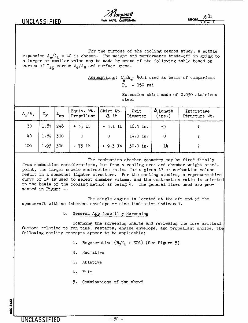
UNCLASSIFIED VAN NUYS, CALIFOINIA
5981
vuL. i
!
For the purpose of the cooling method study, a nozzle
expansion Ae/A t = 40 is chosen. The weight and performance trade-off in going to
a larger or smaller value may be made by means of the following table based on
curves of Isp versus Ae/A . and surface areas.
Assumptions: _/_.= 40:i used as basis of comparison
Pc = 150 psi
Extension skirt made of 0.030 stainless
steel
Ae/A.
3O
4o
i00
cF isp
1.87 298
i.89 300
1.93 306
Equiv. Wt.
Propellant
+ 35 ib
0
- 73 ib
Skirt Wt.
2_ lb
- 3.1 ib
0
+ 9.3 lb
Exit
Diameter
16.4 in.
19.0 in.
30.0 in.
Length
(ins. )
-5
0
+14
Interstage
Structure Wt.
The combustion chamber geometry may be fixed finally
from combustion considerations, but from a cooling area and chamber weight stand-
point, the larger nozzle contraction ratios for a given L* or combustion volume
result in a somewhat lighter structure. For the cooling studies, a representative
curve of L* iS_sed to select chamber volume, and the contraction ratio is selecte_
on the basis of the cooling method as being 4. The general lines used are pre_ _
sented in Figure 4.
The single engine is located at the aft endof the
spacecraft with no inherent envelope or size limitation indicated.
b. General Ap_licabilit[ Screenin6
Scanning the screening charts and reviewing the more critical
factors relative to run time, restarts, engine envelope, and propellant choice, the
following cooling concepts appear to be applicable:
1. Regenerative (N2H 4 + EDA) (See Figure 5)
2. Radiative
3. Ablative
4. Film
5. Combinations of the abov@
UNCLASSIFIED - 32 -
UN CLASSIFIED_ 5981
VAN NUY$. CALIFOIINIA VOL. I
!
With respect to film cooling -- there is an inherent com-
plexity and performance penalty that puts it at a disadvantage when radiation and
regenerative cooling are both possible. Hence, it is considered non-competltive
in this problem. Furthermore, where the propellant weight is large compared to
the chamber weight as in this case, performance penalties are even more critical.
A performance penalty of 2% I_, in terms of propellant reguirement, would cost
more than the weight of the thrust chamber.
e. Preliminary Design Comparison
(i). Weight Analysis
Preliminary design layouts and structural weights may
be calculated using curves such as the following:
i. Throat diameter versus thrust and pressure
(Figure 15)
2. Exit nozzle surface area versus expansion ratio
and throat diameter (Figure 18)
3. Combustion chamber surface area versus throat
diameter and contraction ratio (Figure 17)
4. Expansion nozzle length versus throat diameter
and expansion ratio (Figure 16)
For each cooling method there are plots of typical
structure requirements as a function of chamber size and chamber pressure either
in Volume I or II. Some of these are:
io Combustion chamber reinforcement and passage
weight versus throat area for regenerative
cooling
2. Char depth versus run time for ablative chambers
3. Equilibrium wall temperatures for different radia-
tion cooled operating conditions
4. Ablative thrust chamber weight versus run time,
chamber pressure and thrust (Figure 40)
e
1
Radiation cooled thrust chamber weight versus
thrust and chamber pressure (Figure 36)
Throttling limits for regeneratively cooled
chambers
7- Coolable expansion ratios for regeneratively
cooled designs
I]MRI A_IFIFD

UNCLASSIFIED8_ 5981
VAN NUY$, CALIFOI_IA IRFOIT.... VOL..I.
8. Structural material capabilities
9- Regeneratively cooled thrust chamber weight
versus throat diameter (Figure 34)
Preliminary thrust chamber designs and thrust chamber
weights may be obtained using the above graphs. These weights may be calculated
for a range of chamber pressures as shown in Figure 19. Comments on the designs
represented by these weights are given below.
(2). Regenerative Coolin_
i. Regenerative cooling is possible with (N2H 4 + EDA)
but not with Aerozine-50.
. Allowable chamber pressure ranges for 4:1 throttlin
and minimum passage size of 0.062 inch are given
below (Reference Section III-A of Volume II).
Thrust
500 ibf
2000 ibf
Pcma x
60 psia
240 psia
_pCmi n
30 psia
120 psia
e
4.
Cooled expansion ratio = lO:l. Assume radiation
cooled refractory metal skirt from Ae/A . = lO to 40
Propellant supply pressure variation with fixed
orifice injectors at
Pc = 60 psi, Psup = 95 psia
Pc = 240 psi, Psup : 700 psia
For a two-thrust level design, a variable area
injector could be used to reduce the propellant
supply pressure variation.
Design considerations to be evaluated in more com-
plete design study include:
Meteoroid damage
Zero gravity effects
Freezing of propellant in cooling passages
during deep space coasting
Cut-off impulse accuracy
UNCLASSIFIED - 34-
UNCLASSIFIED VAN HUY$. CALIFOINIA5981
VU.b, I
UNCLASSIFIED
(3).
(4).
6. Weights in Figure 19 include weights of
Chamber reinforcement
Cooling passages
Manifolds
Fuel in cooling passages and manifolds
Radiation cooled, 0.020 inch columbium
skirt from Ae/A . = i0 to 40
Radiation Cooling
l. The maximum allowable theoretical equilibrium
chamber wall temperature = 3300°F with wall
emissivity = 0.72. This limits chamber pressure
to 50 psia (Volume II).
2. The effects of internal radiation and axial
heat conduction are considered minor.
o The chamber material is silicide coated 90_ Ta-
10% W alloy with a minimum gage of 0.020 inch.
A less dense metal such as stainless steel can
be used in the expansion skirt at area ratios
where the equilibrium wall temperature drops
below 2000°F (Figure 36).
Ablative Cooling
i. The char rate is independent of chamber pressure
over the range of interest.
.
B
A duty cycle requiring several closely spaced
firings increases the char rate over steady
state or widely spaced firings. This chamber
is designed for i000 seconds of steady state
firing.
The chamber material is silica fiber (oriented
cloth) reinforced phenol_.
o The chamber pressure stresses are taken by
either metal can or fiber glass wrap (Assumed
equivalent for weight study).
. The use of a hard throat insert may be required
depending on the chamber pressure and injector
design. Maintaining the throat becomes more
difficult at the higher chamber pressures. The
choice has small effect on chamber weight.
35-
UNCLASSIFIED VAN I_JYS. C.ALIFOIt41A
. Figure 19 shows two ablative chamber designs.
The use of ablative material all the way to
40:1 may be required if there are limits on
the outer wall temperature. If the skirt is
free to radiate, a refractory metal skirt may
be used beyond the area ratio producing
equilibrium wall temperatures below 3000°F
(taken as lO:l for design study).
d. Factors Affectin_ Final Choice
In this particular problem, the long run time of 726 seconds
and the 4:1 throttling range are the most demanding requirements. The lightest
chamber design shown by Figure 19 is the regeneratively cooled chamber operating
at 250 psia at the 2000 pound thrust level. Two factors which affect the choice
of the regenerative cooling design are the requirement for either a high propel-
lant supply pressure or a variable area injector, and the requirement that thecooling passages be purged after shut down.
The second choice could be either the radiation cooled or
the ablative engine with a radiation cooled skirt. The choice may be based on a
system study which would include the engine envelope restrictions and the propel-lant supply system weights.
Meteoroid effects during the 240 day coast may have an effecton chamber design choice if more data were available.
2. Example 2: Constant Thrust_ Oxygen-Hydrogen Fueled Space Engine
a. Specification of Propulsion System
(i). En$ine Purpose
This engine study was made to demonstrate the variation
of cooling method applicability with thrust and run time for a minimum weight
thrust chamber. The results are plotted in Figure 21.
(2). Pro_ellants
Liquid oxygen-hydrogen
(3). Propulsion Specification
i. Engine thrust = Constant
2. Thrust range = 20 to i0,000 ibf
3. Engine burning time = 3 to lO00 seconds
!
UNCLASSIFIED 36-

UNCLASSIFIED VAN NUY$, CALIFOINIARPOaT
4. Number of starts = i
5. Thrust chamber pressures (Pc maximum)
Radiation cooled, P = 50 psi.q, c
Ablative cooled, P = 150 psiaC
Heat sink, P = 150 psiaC
Regeneratively cooled, P = See Figure 5C
Environmental and Operational R_quirements
i. Engine free to radiate
cated above.
bo
2. No envelope restrictions
3. Convergent-divergent nozzle, Cr = 4, Ae/A . = 40
General Applicability
This study was conducted for the four cooling methods indi-
c. Weight Stud[
Radiation cooled chamber weights were based on Figure 36 for
50 psia chamber pressure. Weights assumed independent of run time for times lessthan lO00 seconds.
Ablative chamber weights were based on Figures 37, 38, and
39 at 150 psia for a reinforced phenolic nozzle throat design. A nozzle throat
insert of coated graphite was assumed for small thrust engines (below 500 pounds).
The heat sink thrust chamber was assumed to be of graphite
with weights equal to or lighter than ablative chambers for short run times. Heat
sink was applied where transient throat temperatures fell below 2500°F.
Regeneratively cooled thrust chamber weights were calculated
for the minimum thrust versus pressure engine sizes shown in Figure 5.
d. Discussion of Results
This study was made for the purpose of defining the general
areas of applicability. Figure 21 shows that, on a weight basis, the best appli-
cations for the cooling met_6ds shown are:
UNCLA SS IFIED - 37 -
UNCLASSIFIED VAN NUYS, CALIFOENIA ImOI.r 5981VOL. I
i. Radiation cooling - Low thrust, long run times
2. Ablative cooling - Low thrust, run times from lOto 300 seconds
3. Regenerative cooling - High thrust, medium to longrun times
4. Heat sink - Short run times
3. Example 3: Constant Total Impulse Engine with Firing Time andThrust as Variable Parameters
In space, some maneuvers such as orbital changes require a partic-
ular total impulse and are not sensitive to firing time (within limits). This
study indicates (Figure 20) that although both ablative and radiation cooled thrus_
chamber weights can be reduced by increasing the run time and decreasing thrust,
ablative thrust chamber weights are affected by the thicker walls required for the
longer run times. Thus, there is, in this study, a weight crossover point at 200
seconds run time with the radiation cooled chamber being the light.st for thelonger run times.
39, and 40.The weights in these curves were taken from Figures 35, 37, 38,
4. Example 4: Mars or Venus Orbital Fli_ht
me
braking propulsion.
Specification of Propulsion S_stem
(I). Engine Purpose - Deep space, mid-course or orbital
(2). Propellants - Space storable 0F2/B2H 6
(3). Propulsion Specification
i. Thrust = 4000 lbf (constant)
2. Run time = 300 seconds (total)
3. Number of restarts = 4
4. Minimum run time = l0 seconds
Maximum run time = 300 seconds
5. Number of engines = 1
6. Specific impulse = 400 seconds
Gas temperature = (6500 @ to 7500°F)
7. Chamber pressure = Fixed by minimum system weight
and reliable operation
UNCLASSIFIED 38-
UNCLASSIFIED VAN NUTS, CALIFOQNIA
!
(4). Environmental and 0perational Requirements
IB Engine location = Free to radiate.
Equilibrium soak temperatures during coasting =260 ° to +I00°F
2. Engine envelope limitations = None
. Engine configuration = Weight study based on
Figure 4, C-D nozzle, Ae/A . = 40, Cr = 4.0,
D. = 4.17 inch
4. 0xidizer/Fuel ratio = 4.0
5- Storage time in space = 250 days
b. A_plicable Coolin_ Techniques (See Table II)
(i). Radiation Coolin_
From Figure 36 in Volume II, which presents radiation
cooled wall temperatures for OF2/B2H _ at Pc = 20 psi, it can be seen that the noz-zle throat temperature would be 3500VF at a radiation factor of 1.2 and would drop
to 2000°F at an area ratio of 10. The compatibility of coated or uncoated refrac-
tory metals at 3500°F with these combustion gases has not been established. Hence,
this is a tentative possibility at best.
(2). Heat Sink - (See Figures ii and 12)
At 150 psi chamber pressure (h = 550 Btu/hr ft2 °F), a
typical heat sink throat temperature using an edge oriented pyrolytic graphite heat
sink would be 4500°F in 300 seconds. At 600 psi, the surface temperature would ap-
proach 6200°F in 300 seconds. The rates of erosion and oxidation of pyrolytic
graphite for these gas environment conditions are unknown but the cooling concept
for a compatible combustion gas is structurally feasible.
(3). Ablative Coolin5
Ablative materials could be considered applicable to a
part of the thrust chamber and exit cone but not to the throat. Even in the com-
bustion chamber, run times of 300 seconds would doubtless cause considerable surfac_
erosion depending on chamber pressure. Experimental data are very limited.
(4). Film and Transpiration Cooling
Figure 47 compares three analytical approaches to film
cooling the exit nozzle with B2H 6 based on References 9, lO, and ll. (Discussed
in Volume II, Section III.) Straight liquid film cooling (Case I) i_bbviously not
practical. Gas film cooling (Case II) also requires a fairly large fraction of the
propellant flow to cool to an exit area ratio of lO. However, if the results for
Case III could be achieved in practice, as little as 3% of the total propellant flo_
UNCLASSIFIED 39 -

ilNCIASSIFIED VAN NUYS. CALIFOItdlAu
VOL. I
would be required to cool the nozzle from ahead of the throat (Ae/A . = i.`5) to
downstream from the throat (Ae/A . = i0). With transpiration cooling, the predicted
performance is about the same, or about 3_ of the fuel required as coolant. Figure
in Volume II, indicates that the amount of coolant required in terms of percent-
age of propellant decreases with increasing chamber pressure.
c. Prpliminar_ Wei6ht Analysis
(1). Thrust Chamber Confi6uratlon
The thrust chamber lines shown in Figure 4 were used for
weight comparisons.
(2). Propellant Weight
(3).
Total impulse at 4000 lbf and 300 seconds run time,
It = 1,200,000 lbf-second
Total propellant weight at Isp = 400 seconds
W = 3,000 lbmP
Weight Comparison
Rough weight comparison based on available curves.
Radiation cooled, Figure 36 at 20 psi W s = ii0 pounds
Ablative cooled, Figure 38 at 150 psi
(with zero erosion) 300 secW s = 93 pounds
Film cooled,
+3_ coolant
Figure 34 at 1`50 psi
Total
_ = 3.5 pounds= 90 pounds
c
125 pounds
d. Factors Affectin 6 Final Choice-
Radiation cooling, even at 20 psia, appemrs to be marginal at
best. The Isp performance at 20 psia compared to 1`50 psia is lower by 2.9%. Thethrust chamber size at 20 psia would be about three times the length and diameter
of th_ 1`50 psia engine. Hence, there would be no weight advantage with radiation
cooling.
The heat sink thrust chamber also appears marginal for 300
seconds using pyrolytic graphite and would doubtless weigh more than 90 pounds or
more than 3_ of the propellant weight.
!
UNCLASSIFIED 40-
IIMC.IA IFIFr) VAN NUY$. CALIFOIlldlAIIEFOIT 5981
VOL. I
The optimum design approach recommended is the use of film
or transpiration cooling in combination with a pyrolytic graphite heat sink throat
insert and graphite chamber liners upstream and downstream from the throat pro-
tected from oxidation by a minimum of protective ±nert film. If the inert film
protection concept can be developed for application to thrust chamber pressures
of 150 psi and above, the use of higher nozzle expansion ratios and smaller thrust
chambers will provide optimum propulsion system performance.
B. Combined Cooling Techniques and Advanced Concepts
The foregoing sections have presented the applicability and limita-
tions of individual cooling techniques. For many propulsion requirements, one of
several cooling techniques may be used so that an optimum design may be selected on
the basis of weight, complexity, or similar factors. However, there are several
propellant systems for which the cooling requirements are of such severity that no
completely satisfactory cooling technique has yet been developed.
Conditions which give rise to these severe environments are the use
of fluorine based oxidizers such as OF2, F2, and CIF 3 in combination with fuels
containing such metals as boron, aluminum, beryllium, and lithium. These propel-
lants give combustion gas temperatures in the 6000 ° to 8000°F range. The severity
of the combustion environment is further increased with increased chamber pres-
sures. Furthermore, the combustion products are usually highly erosive and cor-
rosive on the available refractory metals and carbides.
Throat heat fluxes fall in the 15 to 25 Btu/in. 2 second range at
chamber pressures of 600 psia. At these conditions, the very best inert heat sinks
would reach temperatures of 5000°F in less than 20 seconds. Likewise, the other
cooling techniques which do not involve a performance loss, such as regenerative,
ablative, and radiation cooling will not do the job alone. Therefore, some form
of film or transpiration cooling is required.
If film or transpiration cooling is required, then the objective of
the design would be to minimize the coolant flow required and the attendant per-
formance penalty (in terms of extra propellant or coolant weight required)° Based
on theory, there is a minimum coolant requirement which is based on the surface
area to be cooled and the wall temperature° Therefore, the cooled surfaces should
operate at the hottest possible temperatures at the nozzle throat consistent with
structural integrity. Materials with the highest temperature capabilities are the
graphites, tungsten_ and the carbides of hafnium and tantalum. Structurally,
graphite and tungsten are capable of operation above 5000°Fo The structural capa-
bility of the carbides has not been demonstrated. However, all of these materials
are subject to oxidation and erosion by the combustion gases even at 5000°F.
Therefore, they must be both cooled and protected. Theoretically, this can be
done with an injected film of inert fluid°
UNCLASSIFIED 41 -
UNCLASSIFIED VAN NIJY$o CALIFOINIA5981
VOL, I
Most advanced cooling studies now in progress (References 5, 12, 13,and 14) are related to ways of generating this coolant film either on a transient
basis or by providing a controlled steady state coolant film supply. An excellent
review of work being done on materials and advanced cooling techniques for solid
propellant motors is presented in Reference 13. Development problems lie in the
areas of refractory material formulation, nozzle design and fabrication_ coolant
selection, and sup_l_ techniques. Particular problems include passage plugging by
coolant or combustion products, coolant distribution, starting and shut down
phenomena, limit on run time and thrust variability, and thermal expansion and
sealing provisions.
Advanced combined cooling concepts which have shown promise but so
far have been demonstrated only for limited run times include the following:
i. Porous refractories impregnated with lower melting metals or
endothermic solids such as a subliming salt (Reference 14)
. Porous throat inserts backed by a reservoir of endothermic
heat sink material which absorbs heat in gasification. The
gas flows into the chamber through the porous surface, pro-
viding a transpiration cooling effect (Reference 5)
3. Sacrificial inserts ahead of a throat insert (Reference 14)
4. Coolant in a liquid or gas reservoir which is pumped tocool the nozzle
5. A liquid metal reservoir to supply convective coolant to
the back sfde of thin wall refractory metal nozzle
6. A radiation cooled heat sink of pyrolytic graphite
7. A film cooled heat sink to extend the inert heat sink
running time with minimum performance penalty
, A film cooled convective nozzle with coolant injected
ahead of throat after being used to cool the throat con-
vectively
9. A convectively cooled combustion chamber with coolant dumped
into the chamber just ahead of the nozzle throat
The limitations of these cooling concepts have not been established_
Continued research is required in the development of refractory materials, in the
development of optimum film and transpiration coolant supply systems, and in ex-perimentally defining the actual combustion environments.
UNCLASS IFIED 42 -
UNCLASSIFIED VAN NtJYS. CAUIIOINIAm
IX. REFERENCES
l,
,
o
,
po
o
7.
.
Q
10.
11°
13,
14.
Aerojet-General Corporation Report No. 2150, Vols, I, IIa, and lib: "Research
Study to Determine Propulsion Requirements and Systems for Space Missions",
December 1961.
Bartz, D.R., "A Simple Equations for Rapid Estimation of Rocket Nozzle Con-
vective Heat Transfer Coefficients", Jet Propulsion, Vol. 27, pp 49-51, 1957o
AFFrC TR 61-7, "Research and Development on Components for Pressure-Fed L02/LH 2
Upper Stage Propulsion Systems, Ablative Thrust Chamber Feasibility Firings",
Lonon and 01cott, February 1961. CONFIDENTIAL.
Marquardt Report M-1808, "Investigations of Non-Regeneratively Cooled Rocket
Thrust Chambers and Nozzles", 20 June 1961. UNCLASSIFIED.
Bartlett, Eugene P., "Thermal Protection of Rocket-Motor Structures", Aerospace
Engineering, January 1963.
JPL Space Programs Summary No. 37-10, Volume II, August 1961. CONFIDENTIAL.
ASD-TR-61-439, "Part I: Criteria for Plastic Ablation Materials as Functions
of Environmental Parameters", MeFarland, Joerg, and Taft, Aerojet-General
Corporation, May 1962.
JPL Report TR 32-58, "Review of Results of anEarly Rocket Engine Film Cooling
Investigation at the Jet Propulsion Laboratory", W. E. Welsh, Jr., March 1961.
NASA Report TN D-130, "Use of a Theoretical Model to Correlate Data for Film
Cooling or Heating an Adiabatic Wall by Tangential Injection of Gases of Dif-
ferent Fluid Properties", J. E. Hatch and S. S. Papell, November 1959.
Jet Propulsion Center, Purdue University Report 1-62-2, "Effects of Selected
Gas Stream Parameters and Coolant Physical Properties on Liquid Film Cooling",
D. L. Emmons and C. Fo Warner, January 1962.
Jet Propulsion Center, Purdue University Report TM-62-5_ "Effects of Selected
Gas Stream Parameters and Coolant Physical Properties on Film Cooling of Rocket
Motors", D° L. Emmons, August 1962°
Kaufman, W. F., W. H. Armour, and L. Green, "Thermal Protection of Fluorine-
Hydrogen Thrust Chambers by Carbonaceous Materials", ARS Journal, October 1962.
Ford Motor Company, Aeronutronie Division Publication No. C-1869, "Applied Re-
search for Advanced Cooled Nozzles" First Quarterly Report, 15 October 1962,
W. H° Armour. CONFIDENTIAL.
Robinson, Ao T°, et al., "Transpiration Cooling with Liquid Metals", AIAA
Journal, Vol. I, No. i, January 1963.
UNCLASSIFIED - 43 -

UNCLASSIFIED VAN NUYS, CALIFORNIA RtPORT.5981
V!)L. I
m_
Of _j
O_
ijl_ __j
< -
Zll
J
I_i_;i
I,-?'< i r2_
,]j=
i
:_
@
i -
>>>>>< <>>i _<
UNCLASSIFIED - 4_ - _ z

UNCLASSIFIED VAN NUYS, CALIFORNIAIIEPOllT 598z
VOL. ;I;
o
c
s #0
L
cp {i_
.- oI
(.J
w
m
_ac o o.-
'_2_ g _ _0__ _ 0_ _L _
_ _,_u ';_ .
_,_ -o -2'-
- i--o _ > c L
_ .-_a:i: v m ,_: u_
@ • • @@
>-
•_ _'__ _ ,_-I11 > _,- >"
0
o _
_ .- g =
,.,I
0 °
U.I
,- ._ .
_m u
'T< "
m
o° _ .o__,o __" ._o ,-o 0 0 _,-_
- _ "o __ _-_ '_" __'_>'- . =_,_"_ _ _°'_ _o'-°_-_ _i,-,,-._ _ 8 ,_,-
•- o_ v o.o.
o .... _-_'-
8_ _.?/8 _ .--
_o ._.- .m o_u
_o._o__o o _ •
.....oX_ ......
..... _._
_ .- o
m
.- _ m E
=c ;T
>z
2
f0
v_
_g_D
LI
E
8
:I:
z
=£
_r_
C)
e_
w_
OO
• 0 @ •
.- _._
::=
o"e4
:=: :c:
::E :=: ::=
=_ _
0
@ @ • • •
",0
U
IINC.I A££1FIFI) - _9. _B_ zz
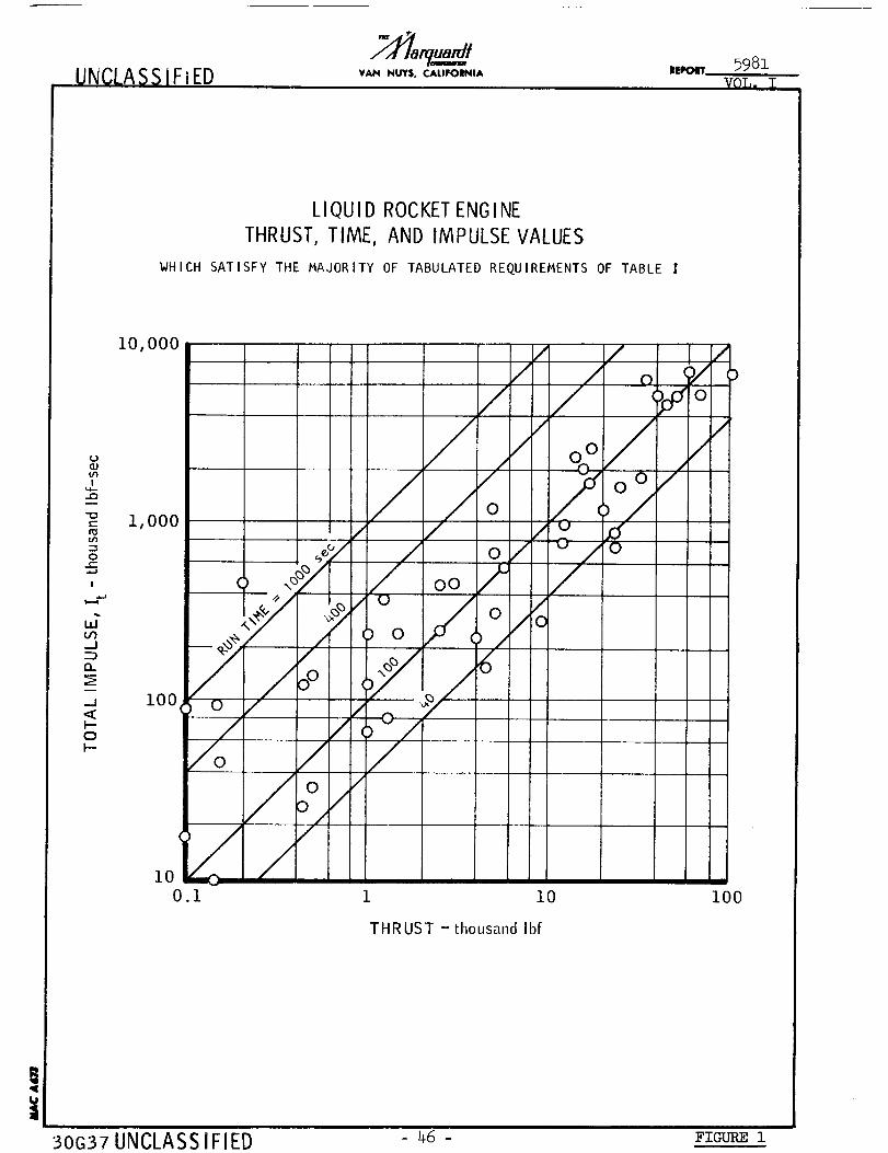
UNCLA SS IFiED VAN NUY$, CAI.IFOINIA ILr_IN_,,5981
VOL. I
LIQUID ROCKETENGINE
THRUST, TIME, AND IMPULSE VALUES
WHICH SATISFY THE MAJORITY OF TABULATED REQUIREMENTS OF TABLE
i0,000
U
..Q
-_ 000
tn
0e-
l
-J
D
I1
_j i00<
o
i00.I i i0 I00
THRUST - thousand Ibf
30G37 UNCLASS IFIED 46 - FIGURE i
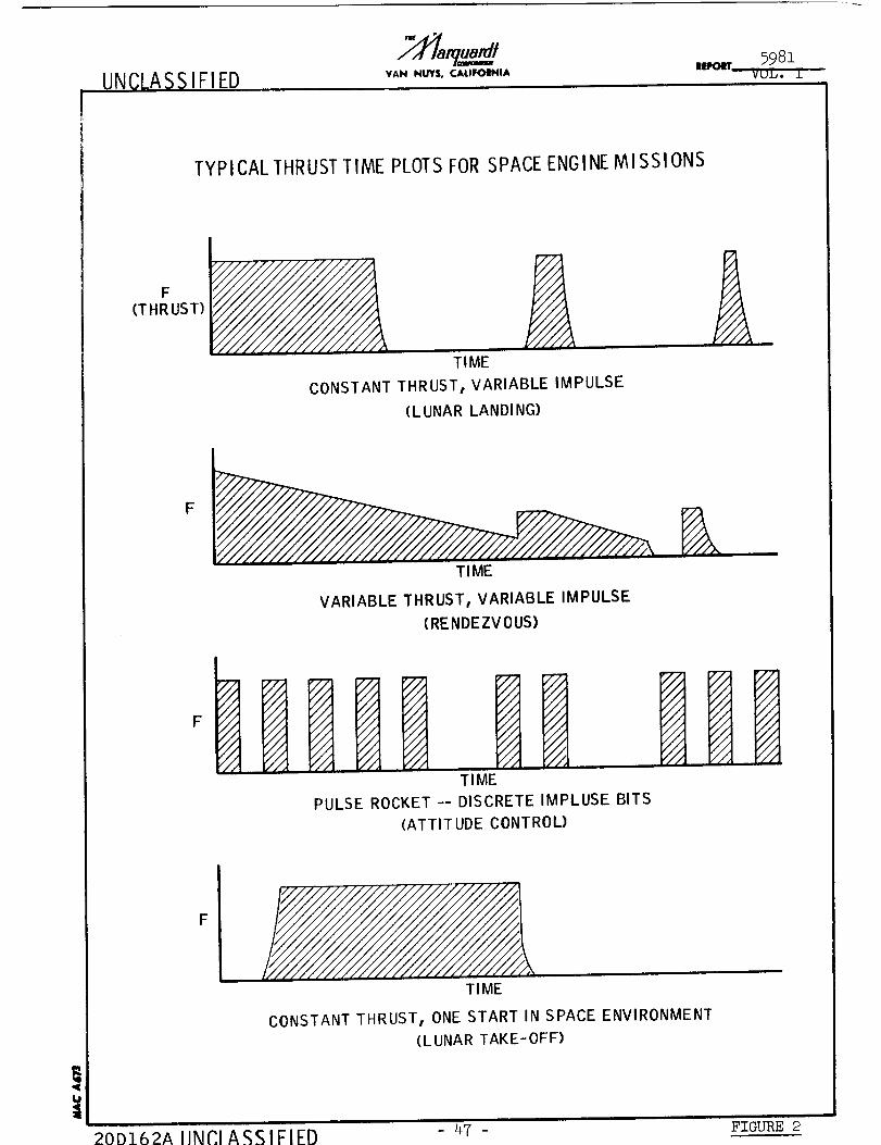
UNCLASSIFIED |lfFOlrr
TYPICALTHRUSTTIME PLOTSFORSPACEENGINENil SSIONS
F(THRUST) £
TIME
CONSTANT THRUST, VARIABLE IMPULSE
(LUNAR LANDING)
F
TIME
VARIABLE THRUST, VARIABLE IMPULSE
(RENDEZVOUS)
F
TIME
PULSE ROCKET -- DISCRETE IMPLUSE BITS
(ATTITUDE CONTROL)
F
TIME
CONSTANT THRUST, ONE START IN SPACE ENVIRONMENT
(LUNAR TAKE-OFF)
i
20D-162A IINCI A%%IFIFI_ 47- FIGURE 2

UNCLASSIFIED VAN NUYS, CALIFOINIA ||I,_IT
o_
_.t.-om
g _-uJ_a:z
xz
z_,_NIC>NO
_ p.=z
Z
z
o =_
co =_z o_
O w_.--
_-ooO u.mL,J0.
=_-
o. __
_OOW __o
_z_ o
QuJo
UNCLASSIFIED
_-<_
0. ,_ c.) o
m
u. m
=<,
o _=
u_Jo_
w_m
R_
u.
°o
o_
_W
o
zz _ zz
53 _3
wJ--
w_c_
_Qm_
o_-oso-
ooz
I ,
• F-mooo_o
.j_
o. -- >- - ---
_'° _=o__wmo -_.Jo.
p-.J
w_
m_
_z
z_ z_ _ z_
_oo_u_
W_ W_
P-o
Z=F- Z_7-
_-=
z
_ o _oo " o_
Z_= W
-- <u u. -
48 FI( m 3
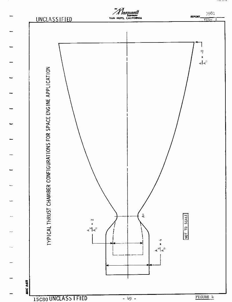
UNCLA SS IFIED VAN NUY$, CALIFOIINIA
5981
VOL, I
w
!
Z0
t--
.--Jc_Du.
IJ.I
Z
0ZLaP
I.m-IC.D
r-,
r_0
Z0
(,.9
l,Z00
-1-(.D
p--Lf_DD_-1-_--
Q_
t3_>-
15c8o UNCLAS_ I FlED - 49 - FIGURE 4

UNCLASSIFiED VAN NUY$, CAUFOI_IIA
'_9_1
0
!
I.a.J
Z
N0r_
-1-
_.J
m,- --.-.
m,,."==#0 -----I.I-
,-, ,.,__
I--"
,t+, -H,Wr_
0
n.-"
WI--"
x w
z
\
\
/
\
k
0
0
0
S
0
0
0
c_(xl
msd - 3WOSS3Wd _38_VHO
UNCLASSIFIED _o - H_-_r_
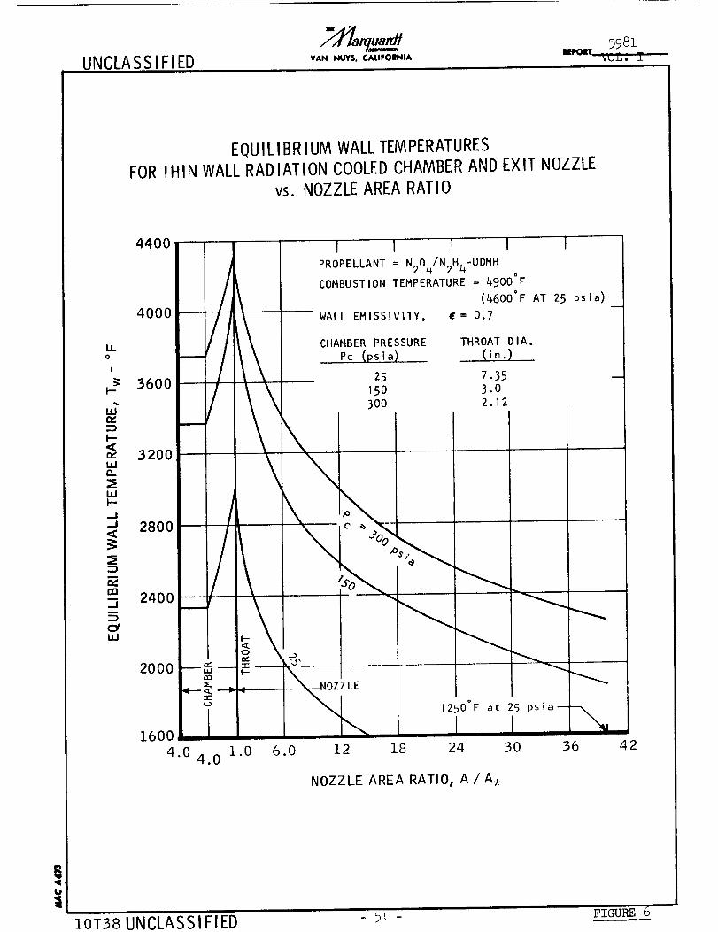
UNCLASSIFIED598z
IIRMI_ .... mvUn,o ..L
EQUILIBRIUM WALL TEMPERATURESFORTHIN WALL RADIATION COOLEDCHAMBER AND EXIT NOZZLE
vs. NOZZLE AREA RATIO
i,o
!
F-
u;
,,irl
ILlI--_J._1,<
--i
,.v,
m._1I
(:YILl
4400
ooo//
36003200
2400 /
I--
2000 --_ --rlm:E
3-
1600 {
4.0 1.04.0
6.0
I I 1 I !
PROPELLANT = N204/N2H4-UDMHo
COMBUSTION TEMPERATURE = 4900 F
(4600°F AT 25 psla)
WALL EMISSIVITY, (= 0.7
CHAMBER PRESSURE
Pc (psia)
25
150300
THROAT DIA.
.....(i_.)7.353.02.12
I
1NOZZLE
12 18
1250°F
24
at 25
3O
NOZZLE AREA RATIO, A/A.
psia%
36 42
10T38 UNCLASSIFIED 51 - FIGURE 6
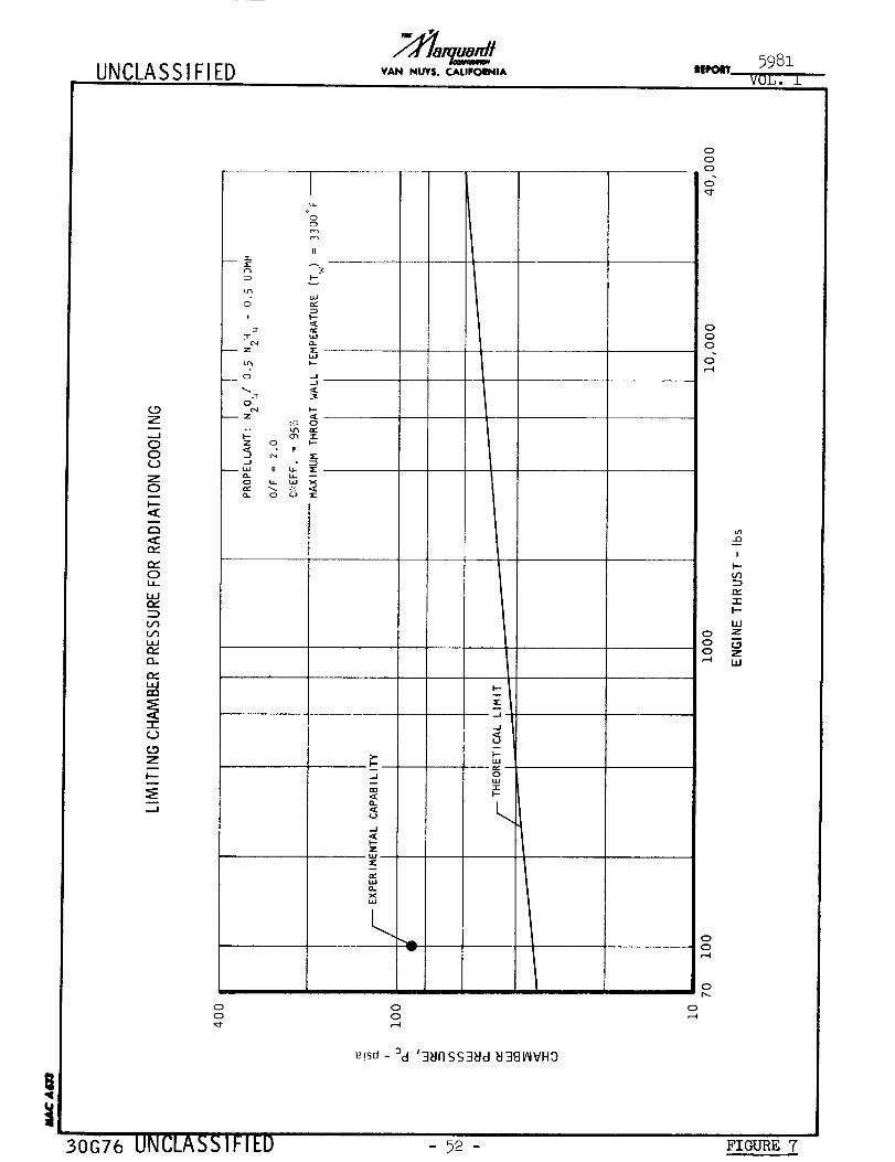
UNCLASSIFIED VAIN NUYS. CALIFORNIA U5981
VOL. ±
(.9g
..J
00
z0
0
i,I
LJ_
(:I.
"I-
<_9Z
.=J
ooo
II
o
u'_ I--
o -I,
Qe,4 _.-
"e,_ Q
¢: p,__ 0 _--II
_J •
>-
_J
o.
z
0_
<w
..J
0
<
0
0
30G76 UNCLASSIFIED
0
0
_!sd - _d '3_IIISS3_Id _I381AIVHD
- 92 -
0
0
0
d
0
0
0
I
i--
--_
I--
UJ
0 _"
Z
00
0
0
FIGURE T
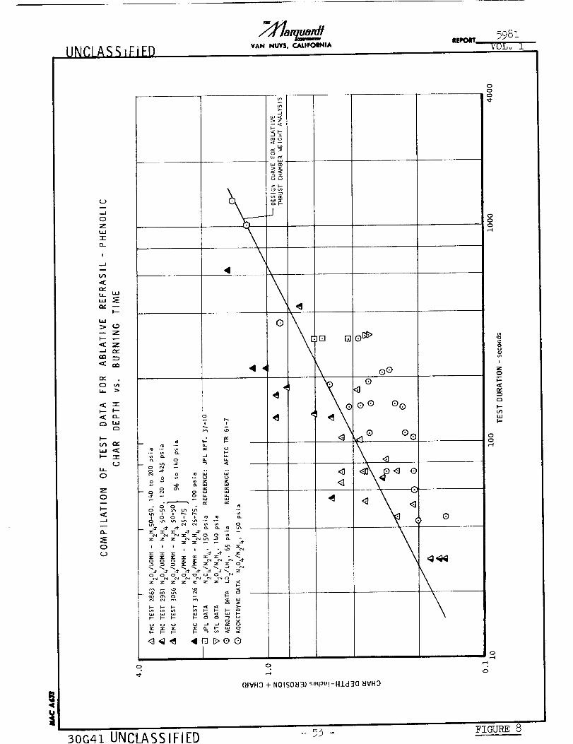
UNCLASSIFIEDVAN NUYS, CALIIFOIINIA
It|POIIT5981
iVOLo i
!
(.3m
..J
0
Z
,,J
-I-
13_
I
..J
Z
_r. z
,:C om
L.L _>
I--- I_
r_
f.-
r,,.
I--- "l-
I..L_
0
Z
0
.-I
Q..
0
_ T
°
¢o .-
._ & _. 0: F-.
o
u'_ N e4 _ u_
, , , ,_i i
z z z z _ z _ _1
__ _ _
0
_[
uc_
J
\
00
000
@00
O@ O@
@ @0
0
r.4
(_IVH3+ NOISO_I3)saq0u!-H-Ld30 _JVH3
00
i
Z0
I--
E3
l--oql.lJI--
0-4
30G41 UNCLASSIFIEDi
5_ _ FIGURE 8
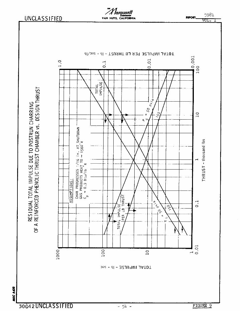
UNCLA SS i FI ED VAN NUYS. CALIFOI_nA
D
"1-C_9 _--ZZ
r_ M
Z >Dm_ P"
LUI-- mm
o_
-r-oq]
F--
D D
-J
_Z..j i,i
0
-JQD
DOr_ u__Z
ILl I.,
I,
0
0
ql/0as - ql - 1SFI_IH1 87 _J3d 3S7i7dlAII 7VIOl
1--I,-4 0
0 0
0as - ql - 3Slfld_l 7V101
0
-1oe--
u'l
oe--
I
F--t/1
O_
7-
I---
!t
30G42UNCLASSIFIED - _4 - Fzam_ 9
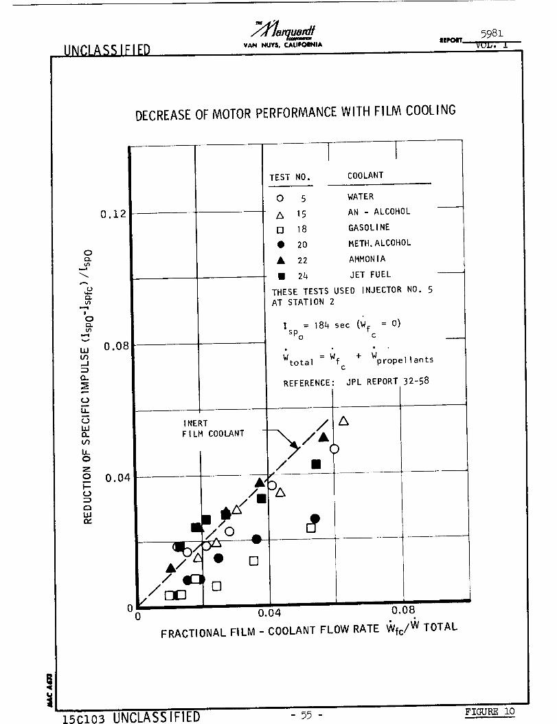
VAN NU¥$. CA,LIFOI_IA IIEI_IT5981
VUL, J]
DECREASEOFMOTORPERFORMANCEWITH FILM COOLING
0.12
o
U3
0
C_LU3
!
o
u3
,,, 0.08Oq
O.
UJ
Lu0Z
o 0.04k-0
(:3l,=
00
TEST NO.
ICOOLANT
0 5 WATER
A 15 AN - ALCOHOL
18 GASOLINE
• 20 METH,ALCOHOL
A 22 AMMONIA
I 24 JET FUEL
THESE TESTS USED INJECTOR NO. 5AT STATION 2
I = 184 sec (Wf = O)
SPo c
Wtota | = Wf + Wpropel]antsc
REFERENCE: JPL REPORT 32-58
l
,I'_ 0
/ elZlZ]_,/z:IE]
0.04 0.08
FRACTIONAL FILM - COOLANT FLOW RATE VVfc/VVTOTAL
!
15C103 UNCLASSIFIED - 5_ - Fzc_m__o
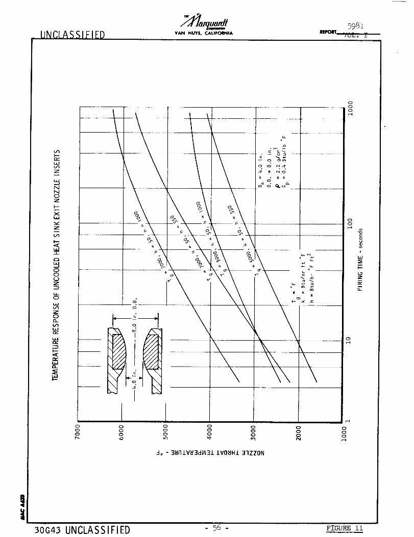
UNCLASSIFIED VAN NUY$, CALIFOINIA
5981
4U.bo m
I--
Z
t',lN0Z
X
z
I--
-r
0o
z
0
Z
0e_
_J
0 0
0 00 0
I0 0
0 0
0 0
0
0
%
O
O
O
O
,--,I
,, ;-.I
0 0 0
0 0 0
0 0 0
3o -3_AlV_3d_31 IVO_H1 37ZZON
o
!
UJ
Zm
,'7
!I
30G43 UNCLASSIFIED - 96 - F I C_JRE ii

UNCLASSIFIED7 2J8
VAN NUYS. CALIFOINIA5981
VOL. I
!I
00
Z000
d
0
00
0
0 0 0 O. 0 C9
0 0 0 0 0 0
0 0 0 0 0 0
30 - 3NNIVN3dF_31 IVO_H1 37ZZON
uo-tD
o
u9
!
UJ
I--
Z
h
30G44 UNCLASSIFIED - 57 - FI_ 12
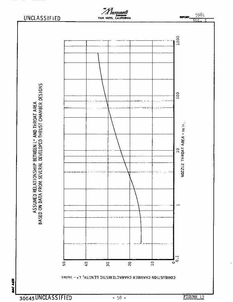
UNCLASS iF iED5981
v0L. T
Z
i
ILl ,,ie_ O0
•:E -Ir-
e_-I-i I
Z-r
Z o-,.,0
_-r_
Z,.,O_
_jO
_Z_0
i,l
O0
00
0
0
0
c
t/3
I
<EI.LI
I--
Qe_
-,e-
..1
N
NQ
0 0 0 0 00
0
30G45UNCLASSIFIED - _8 - Fzc_.r_z3
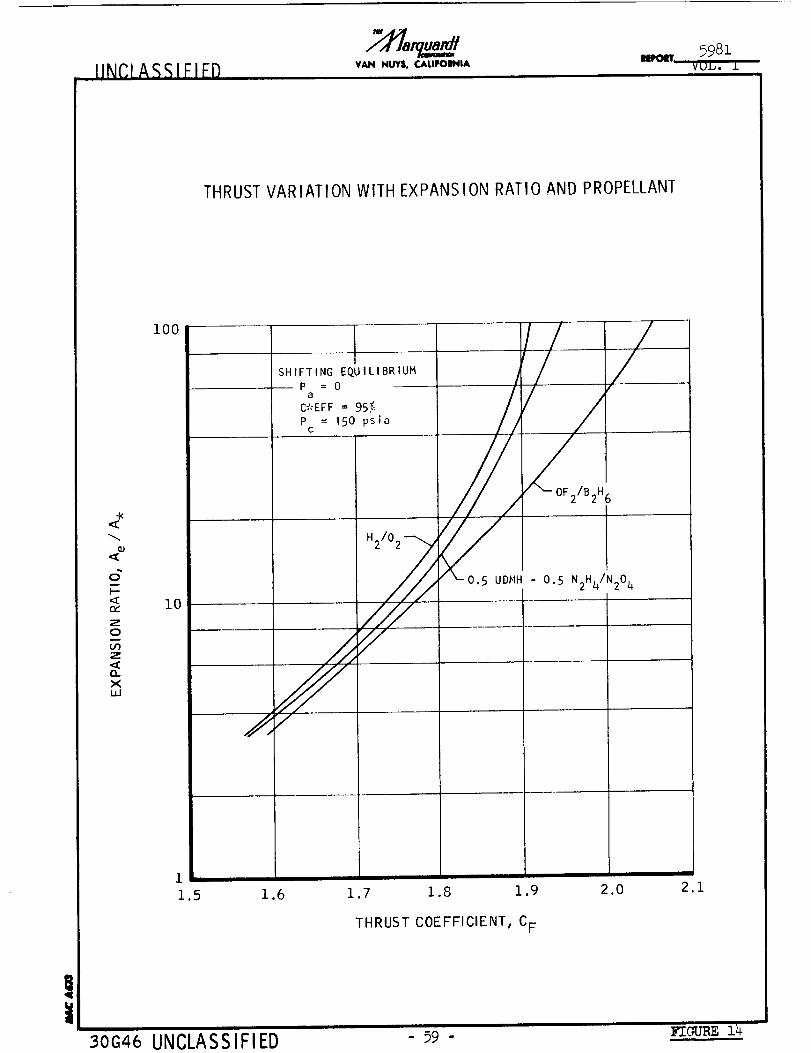
IINCLASSIFIED VAN NUY$, CALIFOI_IA Ul
5981VUI,. I
THRUST VARIATION WITH EXPANSION RATIO AND PROPELLANT
-X
I-
t,K"
Z0
,I.,¢)Z
nXU.I
i00
10
SHIFTING EQUILIBRIUM
Pa = 0
C*EFF = 95'_
Pc = 150 psia
H2/02-- _
S...... I
/
1
1.5 1.6 1.7 1.8 1.9
- 0.5 N2H4/N204
2.0 2.1
THRUST COEFFICIENT, CF
UNCLASSIFIED - 59 - FIGURE 14
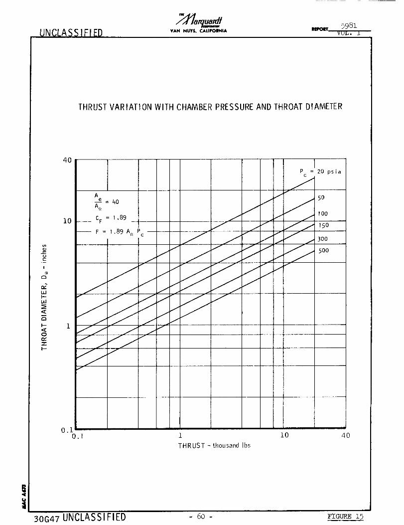
UNCLASSIFIED VAN NUYS, CALIFOINIAim,olT
THRUST VARIATION WITH CHAMBER PRESSURE AND THROAT DIAMETER
6")
C'-
1
4<r',,
WI'--ILl
<r',
"::C0m.,'"I-I'--
4O
10
Ae = 40A.
CF = 1 .89 _
F = I.89 A. PC
P = 20 psiaC
f
i 50
_ ,oo
j 150
...z f
f
1 i0
THRUST - [housand Ibs
4O
I
30G47 UNCLASSIFIED - 60- FZaO_ _
UNCLASSIFIED21%.
VAN NUY|, CALIFOIH'4|AImPOIT
VAR IATION OF EXPANS ION NOZZLE LENGTHWITH THROAT DIAMETER
o
!
r-,
Q?LIJI--LU
<
r,,
I--<
e_"I-I--
4O
i0
1
0.I1 i0
NOZZLE LENGTH - inches
1/2 _
100 400
!
30-G48UNCLASSI FIED 61 - FIGURE 16
UNCLASSIFIED
mw A ;,F
7,[la u_/YAH NI.Rr$, CJ_L|ImOINIA |_pOlrr
5981
VOL0 I
!
L_J
L_
¢=3
F--
or_
.,l-
F-
T--
F--
k--
Z
W
L_J.-J
L=J
W
n-C_)
Z0
F--
L/3
o
0
W
L_J
c.)
LI-
L/3
L_-
o
Z
0
m
F--
\.\
u
0
m
0
\
\
\
\\-4
\\
k-
L_ Z:_ooUJ I-"
/
r_
z
.'2.
,\
I-
I-/_ Z
A
j-5 '
0
0
0
g
\ \
,--4
sa4_u! - _q '_1313_VI0 IVO_IH1
6
I
LU
LU
LL
(,/71
l--Z
W
_4UJ
30G49 UNCLASSIFIED - 62 - Fic-_ 17

UNCLASSIFIED VAN NUY|, CALIPOINIAIIPOIT
!I
rY
w
r_
0
"1-
-r
F-
Z
w
N
N
0
Z
z 5_0 N
Z
X
Z
0
30G50 UNCLASSIFIED
o
saq_u! - Y'O '_313_V10 1VOSH1
63-
o
FIGURE 18
UNCLASSIFIED VAN NUYS. CALIFOIINIA
5981IIEPOIT .....
V_JJ_* J.
THRUST CHAMBER WEIGHTS FOR A LONG RUN, THROTTLING ENGINE
6O0
THRUST = 2000 to 500 Ibs
A /A.,. = 40e ,.
RUN TIME = 726 sec
PROPELLANTS = N2Oq/N2H A + 10% EDA or N204/0.5 N2H 4 - 0.5 UDMH
u_..Q
I
-r
I00W
Wrn
z
k-
e_ZF--
10
\\
\
\\
\
ABLATIVE TO A/A. = 10
RADIATION COOLED: I0 to 40
\
\
\
RADIATION COOLED
\
ALL ABLATIVE
REGENERATIVELYCOOLED TO A/A. = 0 --
RADIATION CO(PLED: 10 to 40
I
\\
\\
\
\
6I0
30G51 UNCLASS IFIED
i00
CHAMBER PRESSURE, Pc - psia
600
- 64 - FIGURE 19
UNCLASSIFIED IEPOIT5981
i
VOL,
THRUST CHAMBER WEIGHTSFOR CONSTANTTOTAL IMPULSE ENGINE
iI--"I"
I.,U
m,,"Wrm
"r
I--
I'--
10oo
i00
i0
1io i00 i000
BURNING TIME - seconds
100,o00
i0,000
m
i
l--u'}
-rI"-
i000
lOO10,000
!
30G35 UNCLASSIFIED - 65 - FIGURE 20
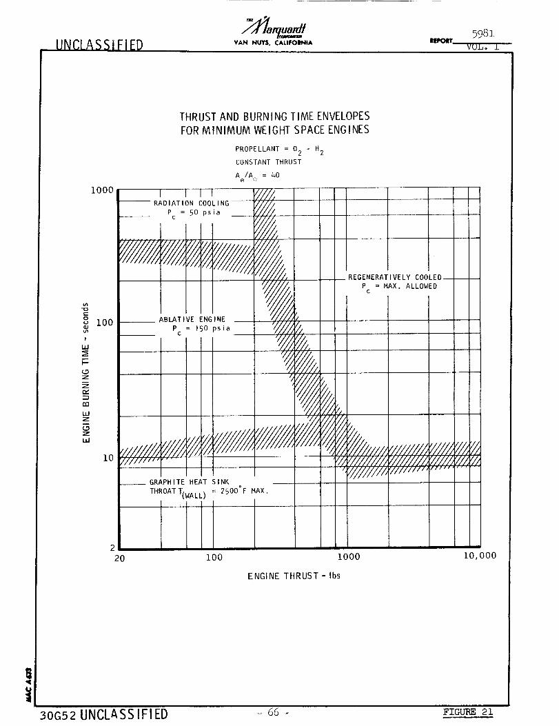
UNCLASSIFIED VAN NUYS, CALIFOIL_IIA Illl, o¢rr
ou_J
I
UJ
F-
g
e_"--1
m
UJ
Z
UJ
lOOO
ioo
lO
THRUST AND BURNING TIME ENVELOPES
FOR MINIMUM WEIGHT SPACE ENGINES
I I I I-- RADIATION COOLING----
P = 50 psiac
t
_,BLAT VE ENGINEP = 150 )sia
¢
PROPELLANT = 02
CONSTANT THRUST
Ae/A.,. = 40
Y//I
,i///i,
J
///ii/i, .....
__GRAPHITE HEAT SINK
THROAT_wALL) = 2500°F MAX.
- H2
/.
?,.
REGENERATIVELY COOLEDP = MAX. ALLOWEDc
¢//,
6
/
/////////_"/////////
'////////,_//////////III/,',
'/////jy////_'////11,'# .. ,
2
20 IOO 1OOO
ENGINE THRUST- Ibs
iO,OOO
!
30G52 UNCLASS IFI ED o 66 - _'zo_m,_23_
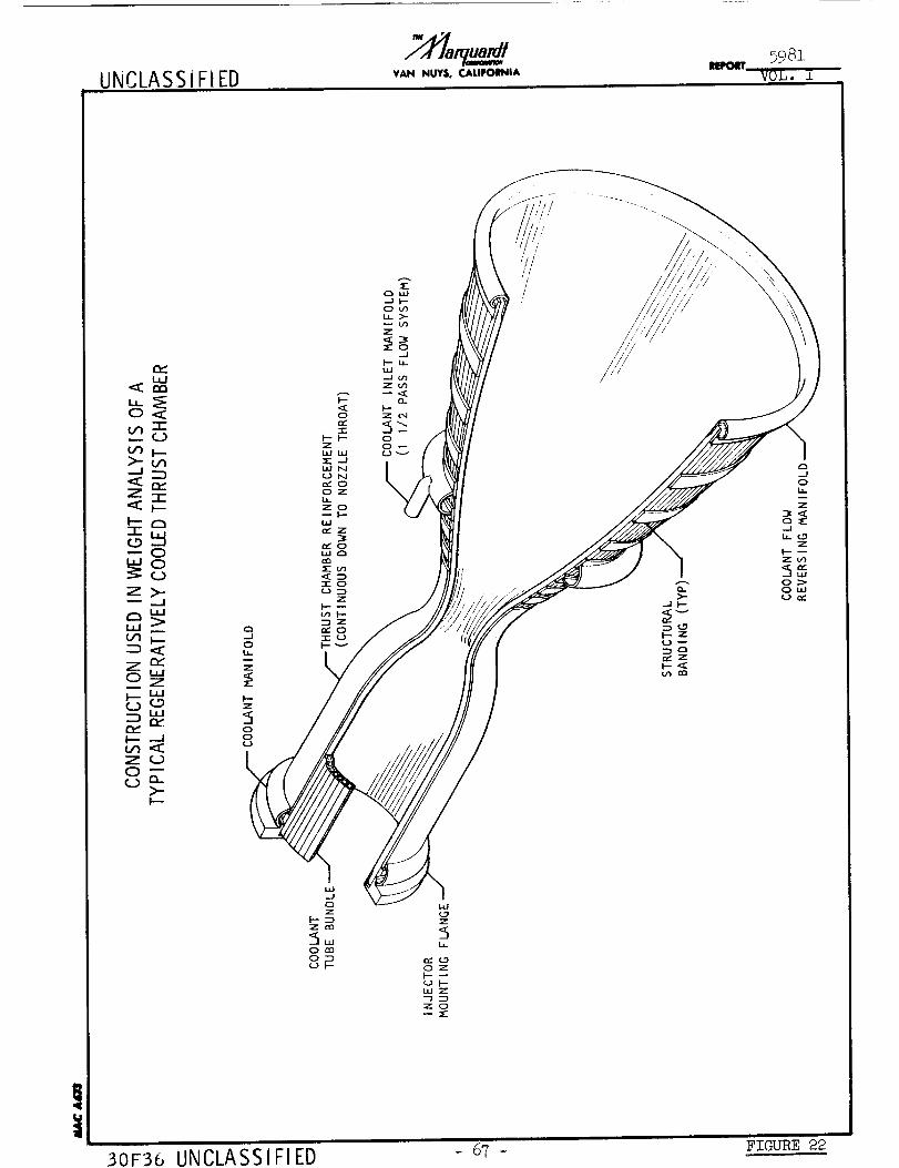
UNCLASS iFIED VAN NUYS, CAI.|FOINIA
5951VOL. i
/
t.ld
•_ es
04
Z -1-
I-- ¢-_-roN--0"'0N_7>--- _.j
t_ I---
Z r_0"' ZF--- ILl
I---- _
Z _-_0 _
_J
0
Z
Z
500
Iii i
FIGURE 22
30F56 UNCLASSIFIED
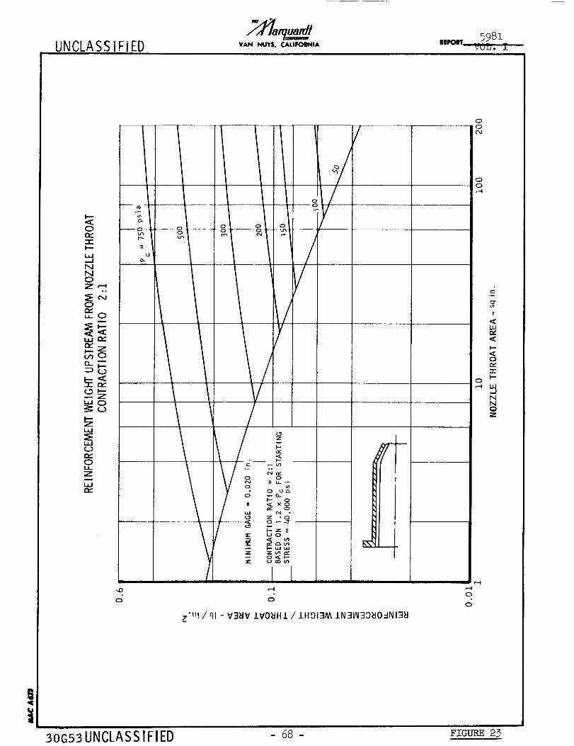
UNCLASSiFiED VAN NUYS, CALIFOIINIA
5981ns,om" VOL.
k -
O --o-
-i-_-- 11
0.uNN
o~_N
° o
zL.U
QD
Oi,Z
,D
O
_ 8g_
0
/00
/
%
%
00
_'u! / ql - V3_lV IVO_IH1 / 1Hgl3AA IN3_3:)_IO=INI3H
0
r--I0
0
I
<uJ
<C
I'--<C0m,"-r"I'-
NN
Z
30G53 UNCLASS IFIED - 68 - Fzo_ 23
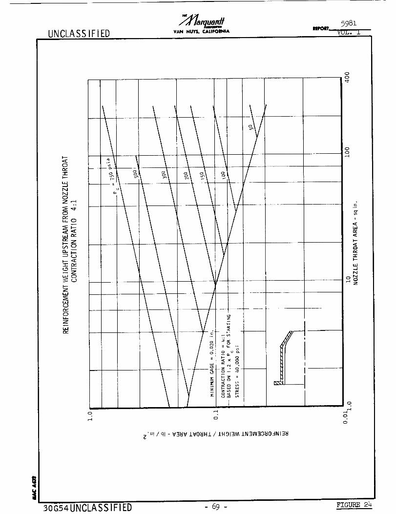
!
UNCLASSIFIED
o
"T" o
N0Z
oe_,, 0
e_
_-g
"rrY
_8Zw
¢,y
0
Z
o
30G54 UNCLASSIFIED
VAN NUY$, CALIFOINIAitiporl
5981
VUL. ±
\ !
° S
0
'U! / ql - V3_V IVOBHI / IHDI3AA IN31AI30_O_-INI3_
00
00,-4
E
!
hl(:d
I--
0OC-rI-
uJ
N
0
t-M
0
0
69- FIGURE 24
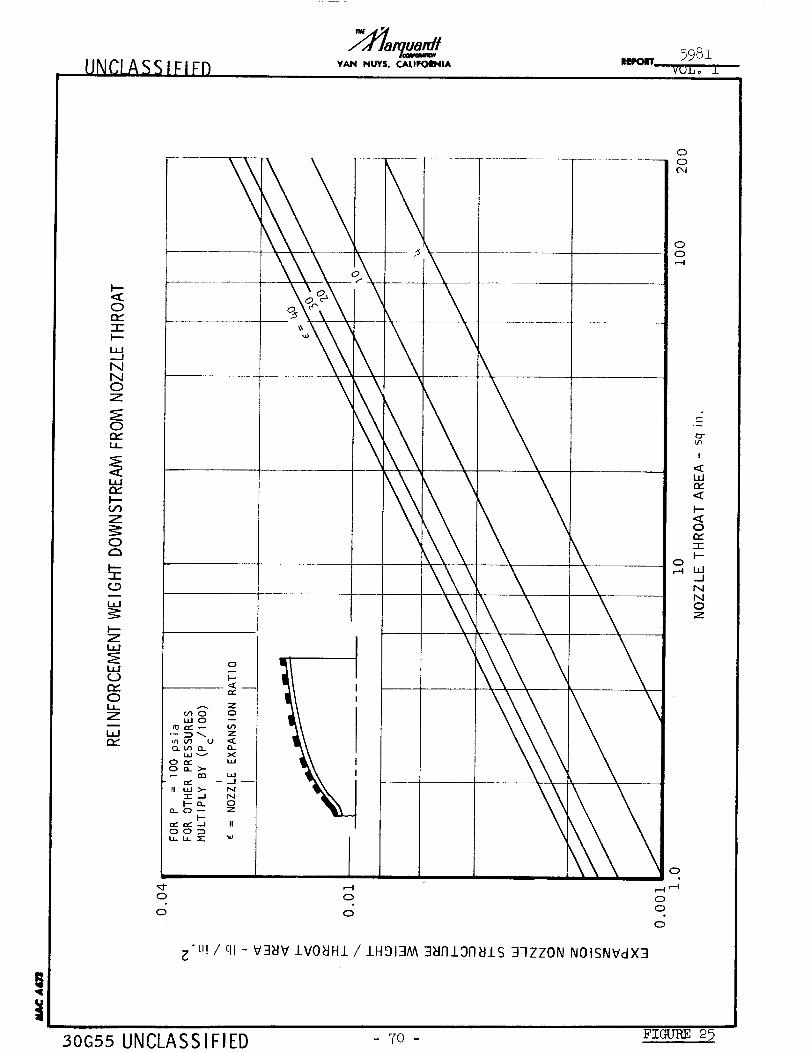
UNCLASSIFIFD VAN NUY$o CAI.IFOINIAIRPolrr 5981
Vt;J_ o .L
h--<K0
-rh--
L__-J
NN0Z
0e_I.J-
I---
Z
0
Z
0
ZI
0
0I'M
\
oiI.-
re'
Zo o
L,t.I 0
• -- _ Z
0-_ O- 0-
0 _ Lit0 Q->-
II _ >- N"1- .--I N_- ,", 0
O. O_ ZI--
,,," ,,," -J Ito0_u_ !a.. _'" ,o
0
0
0
0
0
_'j - 2
rIi r,--I
00
0
_-u! / ql - V3_IV 1V0_JH1 / 1HDI3M 3WITIOn_JIS 37ZZON N01SNVdX3
,t:=r
I
<LI.I
<I'--,<O
7-I--
._JNNOZ
30G55 UNCLASSIFIED - 7o - Fzc,u_ 25

UNCLASSIFIED VAIN NUYS. CALIFOINIAIllf_lT 5981
VQL. I
Op,--I-
NN
oo_L:-
I,,m,,
D
c.9
W(_9<f
U')
_u
OOQD
C,l
o
O
I!
i,iz
-v-t--
.J
--J /<j<
///
-- 0 0 0 0
00Cq
00
0 O"u_
!
uJm,,.<I--.<ot_n-F-ILl_1NN0Z
0
"n
o o
gm
3OG56UNCLASS IF! ED
"U! / ql - V3NV IVO_HI / IHOI3M 39VSSVd
- 71 - FIGURE 26
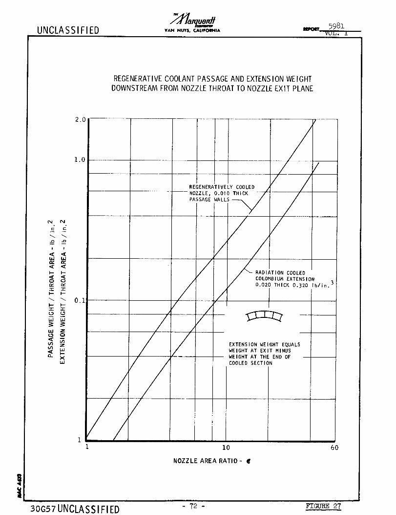
UNCLASSIFIED VAN NUY$, CALIFOI_IA
REGENERATIVE COOLANT PASSAGE AND EXTENS ION WEIGHT
DOWNSTREAM FROM NOZZLE THROAT TO NOZZLE EXIT PLANE
2.0
1.0
_J P4
! !
IJJ I_JIZ IZ
<: <C
Q Or_ ¢Z
-r- "I-
I-- P-"i- -r-
C._ LD
UJ LIJ
UJ ZQ
m z
xw
0.1
/
30G57 UNCLASS IFIED
/
/
REGENERATIVELY COOLED /
NOZZLE, 0.010 THICK ,/
PASSAGE WALLS-_
///
/
/
//
RADIATION COOLEDCOLOMBIUM EXTENSION
0.020 THICK 0.320 Ib/in.
EXTENSION WEIGHT EQUALSWEIGHT AT EXIT MINUS
WEIGHT AT THE END OF
COOLED SECTION
10
NOZZLE AREA RATIO- E
6O
- T2 - FIGURE 27
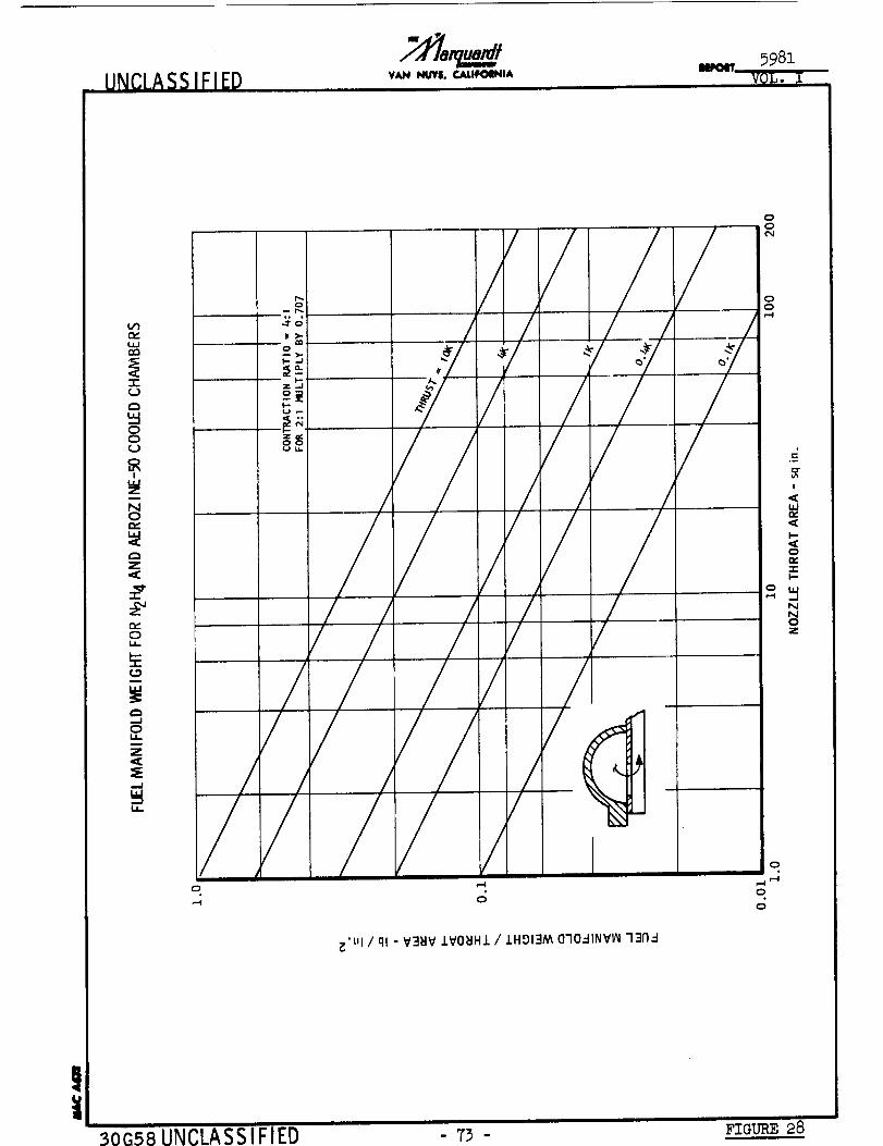
UNCLASSIFIEp VAN NUYS, CALIFOINIA
V1
_J
00
I
m
N0
c_Z
c_0i,
0u_
Z
,.J
LL.
T_
3Gn >-
o
_-..J
z_
8_
/
/
/
j
/
/
/////
i
_'ul / ql " V'=J_IV .LV0_IH.I. / .LHOI3M (3"I0..-IINV_ 331'1.-I
oo
O
,-4
o
I
,,¢u.In,,
I-,
o
-r"I-
NOZ
3oG58 UNCLASSIFIED - '73 -i
FIGURE 28
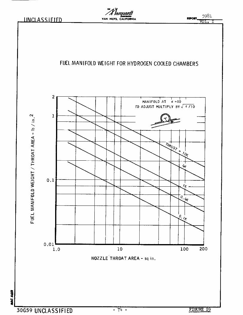
IlNCI ASSIFIED VAN NUY$, CALIFOINIA5981
-TZZT'T'---
FUELMANIFOLD WEIGHTFORHYDROGENCOOLEDCHAMBERS
04
I
,<Wm,,<I--<0n-"1-I--
I--
w
-J0U.7<
LLI
i,
2
0.1
I I I I wMANIFOLD AT (=I0
ro ADJUST MULTIPLY BY,,/ _/10
...., I
_o "--.,,
0.01
1.0 10
NOZZLE THROAT AREA - sq in.
i00 200
30G59 UNCLASSIFIED - 74 - Fz_ 2_

UNCLASSIFIED VAN NUTS, ¢,ALIFOINIA/
5981
VOL. I
O
"I-
NNOz
O
LL.
O_-7
b_
O
>
b_J
(O
ZO
i,i_0
C.9
W
Z
_.JOO
O
--II _ --0
z
N_ m
//#
/
i_ ,_- i_ o,I ,-i
o o o o o
_'t,! / ql - V3_V IVO_Hl / IHOI3AA 1NV700D
oo
oo
o,--i
o
,--I
0
0
!
w
I--
0n,"-r-l--
_JNNO
30_60 IIMP.IA99 IFIFB - 79 - FIOU_ 30

UNCLASSIFIED VAN NUY$, CALIFOWNIAmEPOIT
COOLANT WE IGHT BASED ON JACKET VOLUME DOWNSTREAM FROM NOZZLE THROAT
exl
c
!
LIJe_,,¢
I.--,¢0
-rI---
l---r-(.D
ILl
I--Z
OO
C.)
1.0
0.i0
0.01
0.0071
//
BASED ON p = 56 pcf
FOR OTHER DENSITIES
---MULTIPLY BY (P/56)
AEROZINE-50 P= 56 pcf
HYDRAZINE P= 61 pcf --
HYDROGEN p= O.l pcf
10 40
NOZZLE AREA RATIO- E
!
30G61 UNCLASSIFIED - 76 - FIGURE 31

UNCLASSIFIED VAN NUY$. CALIFOINIA5981
vQL,
COOLANT WEIGHT BASED ON FUEL MANIFOLD VOLUME FOR AEROZINE-50 AND N2H4
0.0011 i0 I00 200
NOZZLE THROAT AREA - sq in.
!i
30G62 UNCLASSIFIED - 77 - Fza_ 32
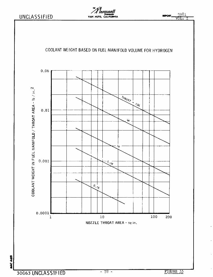
UNCLASSIFIED VAN NUY$, CALIFOIINIAIIEFOIIT 5981
VOL. I
COOLANT WEIGHT BASED ON FUEL MANIFOLD VOLUME FOR HYDROGEN
I
ILl,,v
I--
0
"t-I--
a--I0
Z
-JW
1.1_
I---t-
I.zJ
I--
<_--I00
0.06
0.01
0.001
0.000110
NOZZLE THROAT AREA - sq in.
100 200
30G63 UNCLASSIFIED - 78 - FIGURE 33
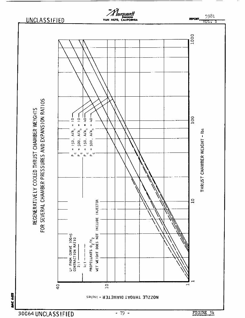
UNCLASSIFI ED VAN NUY$, CALIFOINIAIIEPOIT
5981
VOL, 1
!
O
CD Z
,,, O
Z
e_ a_
xua
-i- g3Q_) Z
D ,,,
-I- D
O O_
>_ mm
7-
_._ Q-)
QZ
Z ,,,w >QD ,,,
e_
Ol.a.
o
\
L_ O U_ O
II II II II
U U '.J'--
0,--'I
0 --I--
LIJ --.--)Z
_JL)Z
_._" Q
N UJ,,,_1 I oo
! °_ Z -r"
..
5o ,,-,_
I
saqm'! - _I3131AIVIa IVO_JH1 37ZZON
000r-.l
00,--I
0,--I
I
l---r(.9
LW
n,-iJ.lrn
-rtJ
I.--
Dtw
-rI--
,-4
30G64 UNCLASSIFIED 79 - F'raT.m_34

UN(;LASSIFIEDIlliCIT
5981VOL. I
WEIGHT OF RADIATION COOLED THRUST CHAMBER USING 90 Ta-IOW ALLOY
!
I'--"-r-
UJ
-r0
I"-
IX
I,--
1000
i00
I0
1.00.I
I I IIIN2Oh/O. 5 UDMH - 0.5 N2H 4
O/F = 2
CW EFF = 95%
Ae/A, _ = 40
I r/ /
//
/d10
THRUST - thousand Ibs
/
i00
30G65 UNCLA SS IF IED 80 - FTC-URE3_
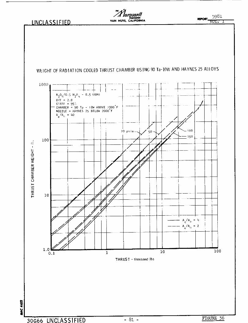
• UNCLASS I FIEDI 598z
VANNUVS,C,_UFONA N_, _u.b. L
WEIGHT OF RADIATION COOLEDTHRUST CHAMBER USING 90 Ta-IOVV AND HAYNES 25 ALLOYS
,)
#
I-
(._
b.I
u..Ien
"w
b--
"rk.-
i000
N204/0.5 N2H 4 - 0.5 UDMH
O/F : 2.0
C_',EFF = 951ii, /
--- CHAMBER = 90 Ta - 10W ABOVE 2000°F ....................................
NOZZLE = HAYNES 25 BELOW 2000°F /J
Ae/A , = 40 /"
/2"/ ¢,
, ,//i [""-- 1O02O ps i a -_.. 5O--.,
I 1 / I , _ ,5o100/ / .,,,Y
/ "// .,/
1o / _ z¢.// ........
./ ///
"/ //" ,,_"
//_ a /A,,.=4
Ac/A . = 2
V .,
1.0 _
0.i 1 i0 I00
THRUST - thousandIbs
UNCLASSIFIED - 81 - FIGURE 36

UNCLASSIFIED VAN NUY$, CALIFOENIAIEPOIT 5981
VOL. A
CHARACTERISTIC ABLATIVE THRUST CHAMBER WEIGHTAS A FUNCTION OF THRUST FOR60 - second STEADY STATERUN
Z!
I--
"1-
i
r_
rn
<"-r
O
IOOO
I00
10
t I l 1-] 1-- MATERIAL: SILICA-PHENOLIC LAMINATE
PROPELLANTS: N2OL/50 UDMH - 50 N2H 4 (TYP)
Ac/A . = q, Ae/A,. = 40
__ CHAR RATE ASSUMED TO BE INDEPENDENT OF Pc-
/
/i
0.1
//
#....i
/
/
10 IO0
THRUST - thousand Ibs
30G67 UNCLASSIFIED - 82 - Fza_ 3T
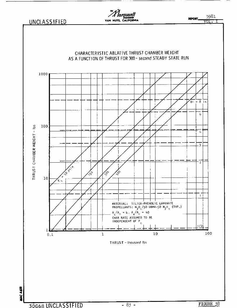
UNCLASSIFIEDVAN NUY$, CALIFOINIA
impolff 5981
VOL o I
CHARACTERISTIC ABLATIVE THRUST CHAMBER WEIGHT
AS A FUNCTION OF THRUST FOR 300- second STEADY STATE RUN
2I
!
I---r_9
hi
=,1r_
<I
t--
re.,"I-I--
1000
I00
// / //
// C///
............ ...._/_¢,z / _/_/_
/ / 3 i
1o</ !_//............. _BI_"
/ /
__ MATERIAL: SILICA-PHENOLIC LAMINATE
PROPELLANTS: N20_/50 UDMH-50 N2H q (TYP.)
Ac/A = 4, Ae/A, = 40
CHAR RATE ASSUMED TO BE
INDEPENDENT OF Pc
0.1 1 10
m
i00
THRUST - [housand Ibs
!i
30G68 UNCLASSIFIED 83 - Fzo_ 38
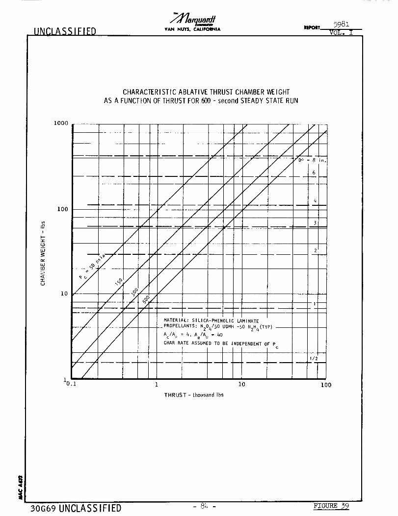
UNCLASSIFIED VAN NUY$, CALIFOINIAIIEPOIT 5981
VOL. I
CHARACTER ISTIC ABLATIVE THRUST CHAMBER WE IGHT
AS A FUNCTION OF THRUST FOR 600 - secondSTEADY STATE RUN
m
!
"1"
W
n_L_rm
-r
1000
IOO
10
/
5(
," / /. /
,z _ ,//
/ /' .....
/
////
MATERIAL: SILICA-PHENOLIC LAMINATE
PROPELLANTS: N2Oh/SO UDMH -50 N2H4(TYP)
Ac/A . = 4, Ae/A . = hO
CHAR RATE ASSUMED TO BE NDEPENDENT OF Pc
THRUST - thousand Ibs
10
! !
I --m - n
112
1I00
!
30G69 UNCLASSIFIED - 84 - FIGU-RE 39
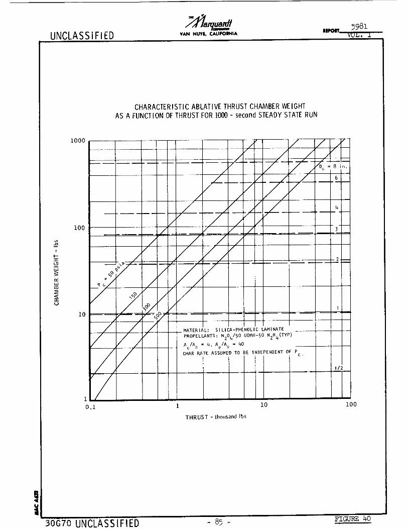
UNCLASSIFIED tAN NUTS, CAIJPOI_IAm,oet,, 598z
VU_° I
CHARACTERISTIC ABLATIVE THRUST CHAMBER WEIGHTAS A FUNCTION OF THRUST FOR lO00 - second STEADY STATERUN
iooo
I00
2,!
"r"(D
UJ
LUm
,o
lO
1
o.I 1 i0 i00
THRUST - thousand Ibs
30G70 UNCLASSIFIED 85- FIGURE 40
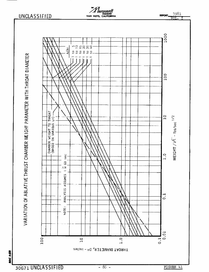
UNCLASSIFIED VAN NUYS, CAUFOINIA iEI,O_r
\_,\,
X- \o \ZIZ
ZIZ _
"' /I---
•_ o_ --_,_ -
-- F-- _ --0
-- "r ¢_' --
L__Z
'D
<<-I- ene..J ,..,_
0
LIJ
ZIZ
e_ZIZ
>
,-.1
0
Z0
I--
<_
0
0
\ \'_,
\
u
o",,D
All
m
>-.../
z<
JI--0z
,' firuc_o Lr%0 0 0
0 0 0 0 0 0
/
\ \'\ _\\,
0
\
\
\ \\\'
\
\
0
0
0,--I
0
0,--I
0
0
r--I
,-4
,--I
0
,_ 0
o
C'4
0_J
$')r_
I
I--"I-
(--9
uJ
30G71 UNCLASSIFIED - 8_ - F_o_ _

UNCLASS IFI EDIPOIT
5981
VCL • I
Z
W
<Io
D
-I-
F--
ILl
>
.--J
--.J
QD
D_>-
0
>-..J
Z
F---1-(_9
0
I---
D
0>-
--.1
Z
0
0
z0
W
.--J
e_
Z
Z
--..I
00
0
0
t_
o
0
o00
0
o
II
0
0
//
/0
0
00
_JN
-J
//
II
00
_o
000
_0
I
Iw
0t_
000
c
0
c_
0
co UA
_o
P- o
_J
T oC_-) -0
L_ o_-AN 0_J -- ne,_ to O-
°°
p-0z
O_
0"_
II
e_
0
)
@
)
0 :
t_
0
0
30G72 UNCLASSIFIED 87 - Fro__ 42
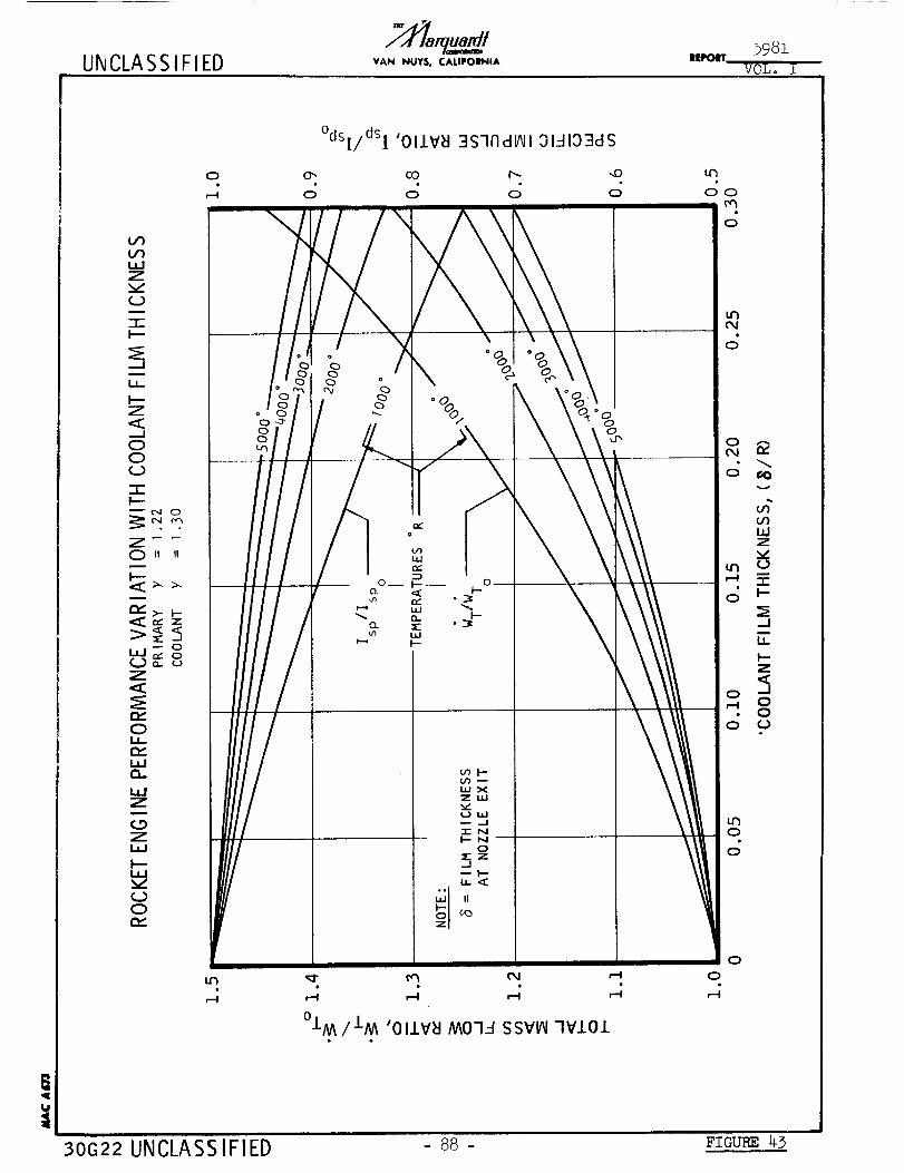
UNCLA SS IFIED VAN NUY$, CALIPOINIA IEpoIITVOLo i
°dsl/dSl 'OIIV_I 3s-IndlAII ,31_-I193dS
0 0", CO I'_ _0 U'h
o o o o o_\ \ o
0
<,
/i i
// !ie i
0 _- "m- oz _o
0
_I" _ C_ _ 0
°IM/IM 'OIJ.Y_I MOI_.-I SSY_ 3YiOl
!
30C_22 UNCLASSIFIED o 88 : Fzau-_ 43
UNCLASSIFIED VAN NUY$, CALIFOIINIA
I---ZILl
LaJ
r_
-.J
Z
F---<COr_II--La.J...JNNOZ
F--LaJ
0Q_
0 o
IIe,J
5: II
0Z
t_0L,
WQ.
I,o
Z0m
m
m_ oN
oo
I
0t_
°dsI/dSl 'OIJ.V_J 3STFIdV_I 3141:)3dS
o',
o
OiU
Q_
0 0 0
"!
0U.
t_
0 I
r-I
0
_o, I1"¢_
0 0O0 0
1
o
,, oL'3 0 ,''_0 Q
_-4 r-I
03/3 'OIJ.V_J .LSII_H.L
0,a..,a
.,l.a
<£
c_i.-
e_
la.Jm,,
I-zl.u
Ld
...IZI.tJ
U
t30GI9A IINP.IASSIFIED " 89 - FZC_ _4
UNCLASSIFIED VAN NU'f$. CALIFOIN|A iE.Poln"5981
VOL0 I
000,-4
-_dLaJ>
D
I
...1 _
D_-9
-,h_vD(..__O
_O
I--
'"O
2_uj
u.J --_r'_ F-.-
_ I-.-
(_),_
O.. e,_
>-OF-- _
O
zO
I---
¢.y
>
u
---D--rag-- -r.--}--E
o__1"--
_.- e¢"Zt_ I.'-
D---_d_
@ @
I
@
@
@
O
O
Or-_
!
I"-
-m
F'-
O O
O
oas - Jql - 3S7FIdlAII
!
30G73 UNCLASSIFIED - 90 - FIOURE _9
UNCLA SS IFIED VAN NUY$. CALIFOIINIA
VARIATION OF SPECIFIC IMPULSE WITH NOZZLE EXPANSION RATIO
i000
!
$
F-
tw
z0
z
o_XLG
LLI.JNN0z
lO0
i0,280 320
/ /
NOTE: i
SHIFTING EQUILIBRIUM
EXPANSION TO VACUUM --
C*EFF = 95%
Pc = 150 psla j
_- N204 / 0.5 N2H 4 - 0.5 UD
02/H2, "_
OF2/B2H6 -7/
L F2/H
/361 400 440 480
SPECIFIC IMPULSE, Isp - seconds
30G74 UNCLASSIFIED - 9_ - ;zou-_ 46

UNCLASSIFIED VAN NUYS. CALIFORNIA llEPo_r 598l
VUI,. I
O_
0
<n-
O_JU_
z<
000
FILM COOLING REQUIREMENTFORTOTAL SURFACEAREAFROM AHEAD OF THROAT (Ac/A':' 1.5) TO AREA RATIO INDICATED
CASE 1: LIQUID FILM CONTINUOUS
1-I-: GAS FILM (JPC RPT. 1-62-2) Tw = 2200°R
]I[: VAPOR FILM (JPC RPT. TM62-5) Tw = 2200°R
1.0
o.8 I ..... J"o._ I
I I "
'I-_---CHAMBER----_q_--_NOZZLE
o._ i II / I
02 I <_ ]• I 0
-r
o._ I /0.08
0.06
0 02 I
0.01 I
o.oo i/// i0 i .5 i .0 2
J
f
JJ
4 6 8 i0
CONDITIONS
OF2/B2H 6
Pc = 150 psiaF = 4000 Ib
ADIABATIC WALL"
20 40
COOLED AREA RATIO, A/A.
30G75 UNCLASSIFIED 92 FTC_ 47
UNCLASS IFIED VAN NUY$. CALIFOIBNIA IIIlII_ITVOL. .L
APPENDIX A
SUMMARY OF NOMENCLATURE
Symbol Description Units
9
A_
Ac
Ae
At
C*
CF
cp
Cr
C-D
D*
EDA
F
g
h
Isp
It
k
L*
L n
MMH
Mf
2Rocket nozzle throat area in.
Combustion chamber cross section area in. 2
Nozzle area at exit plane in. 2
Rocket nozzle throat area in. 2
Characteristic velocity ft/sec
Rocket nozzle thrust coefficient --
Specific heat at constant pressure Btu/lb °F
Contraction ratio Ae/A. --
Refers to convergent-divergent rocket nozzle contour --
Nozzle throat diameter in.
Ethylenediamine --
Thrust (pounds force) lbf
Gravitational constant ft/sec 2
Heat transfer coefficient Btu/hr ft 2 °F
Specific Impulse F/Wp lbf-sec/ibm
Total impulse --
Thermal conductivity Btu/hr ft °F
V cCharacteristic combustion chamber length L* =-- in.
A.
Length of rocket nozzle from throat to exit plane in.
Monomethylhydrazine --
Final mass ibm
IIN I IFIFD - c);5-
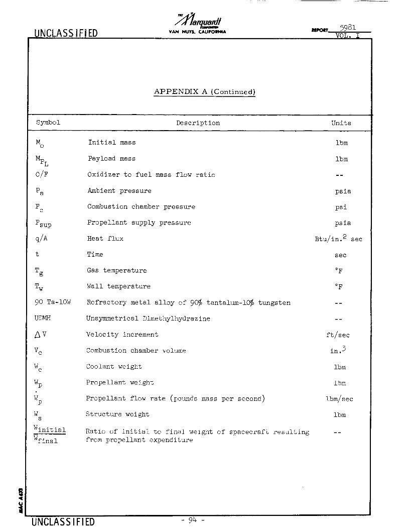
UNCLASSIFIED VAN NUYSo CALIFOINIAIpocrr 5981
VOL. I
APPENDIX A (Continued)
Symbol Description Units
Mo Initial mass ibm
Mr Payload mass ibmrL
0/F Oxidizer to fuel mass flow ratio --
Pa Ambient pressure psia
Pc Combustion chamber pressure psi
Psup Propellant supply pressure psia
q/A Heat flux Btu/in. 2 sec
t Time sec
Tg Gas temperature °F
Tw Wall temperature °F
90 Ta-10W Refractory metal alloy of 90_ tantal_m-10_ tungsten --
UD_ Unsymmetrical Dimethylhydrazine --
V Velocity increment ft/sec
V c Combustion chamber volume in. 3
W c Coolant weight Ibm
Wp Propellant weight ibm
Wp Propellant flow rate (pounds mass per second) ibm/sec
W Structure weight ibmS
Winitial Ratio of initial to final weight of spacecraft resulting
from propellant expenditureWfinal
UNCLASSIFIED - -

UNCLASSIFIED VAN NUI'$. CALIPOINIA_qR1
VOL. I
APPENDIX A (Continued)
Symbol Description Units
Zero g Zero effective gravitational force --
Film thickness in.
Nozzle expansion ratio Ae/A . --
Specific heat ratio --
/<D Density ib/ft 5
!
_tP.lASS IFIFI_,| | ,
- Q% -

UNCLASSIFIED VAN NUY$. CALIFOINIA IIEPO¢IT 5981
VOL, I
DISTRIBUTION
Copy No.
i.
.
,
4to7.
,
t
I0, ii.
12, 13.
14, 15.
Transmitted to
NASA Western Operations Office
190 Pico Boulevard
Santa Monica, California
Attn.: Office of Technical Information
NASA Western Operations Office
190 Pico Boulevard
Santa Monica, California
Attn.: Contracting Officer
NASA Western Operations Office
150 Pico Boulevard
Santa Monica, CaliforniaAttn.: Patent Office
NASA Headquarters
400 Maryland Ave., S.W.
Washington 29, D.C.
Attn.: Chief, Liquid Propulsion Systems, RPL
Mr. Henry Burlage, Jr.
NASA Headquarters
400 Maryland Ave., S. W.
Washington 25, D. C.
Attn.: Asst. Director for Propulsion, MLPMr. A. 0. Tischler
Jet Propulsion Laboratory
California Institute of Technology4800 Oak Grove Drive
Pasadena, California
Attn.: Propulsion Division, Mr. Bruce Johnson
NASA Ames Research Center
Moffett Field, California
Attn.: Technical Librarian (Designee: H. Hornby)
NASA Goddard Space Flight Center
Greenbelt, Maryland
Attn.: Technical Librarian (Designee: M. Moses,n)
Jet Propulsion Laboratory
California Institute of Technology4800 Oak Grove Drive
Pasadena, California
Attn.: Technical Librarian (Designee: R. Rose)
UNCLASSIFIED - 96 -
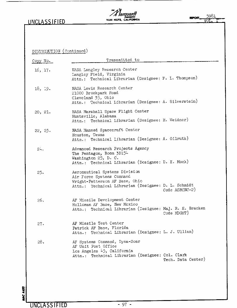
UNCLASSIFIED VAN NUY$. CAI.IFOINIA
,yOL,
DISTR IBUT ION (Cont inued )
Copy No. Transmitted to
16, 17. NASA Langley Research Center
Langley Field, Virginia
Attn.: Technical Librarian (Designee: F. L. Thompson)
18, 19. NASA Lewis Research Center
21000 Brookpark Road
Cleveland 35, Ohio
Attn.: Technical Librarian (Designee: A. Silverstein)
20_ 21. NASA Marshall Space Flight Center
Huntsville, Alabama
Attn.: Technical Librarian (Designee: H. Weidner)
22, 23. NASA Manned Spacecraft Center
Houston, Texas
Attn.: Technical Librarian (Designee: A. Gilruth)
24. Advanced Research Projects Agency
The Pentagon, Room 3D154
Washington 2% D. C.
Attn. : Technical Librarian (Designee: D. E. Mock)
25. Aeronautical Systems Division
Air Force Systems Command
Wright-Patterson AF Base, Ohio
Attn.: Technical Librarian (Designee: D. L. Schmidt
Code ASRCNC-2)
26. AF Missile Development Center
Holloman AF Base, New Mexico
Attn.: Technical Librarian (Designee: Maj. R. E. Bracken
Code _DGET)
27. AF Missile Test Center
Patrick AF Base, Florida
Attn.: Technical Librarian (Designee: L. J. Ullian)
28. AF Systems Command, Dyna-SoarAF Unit Post Office
Los Angeles 4_, California
Attn.: Technical Librarian (Designee: Col. Clark
Tech. Data Center)
!
UNCLASSIFIED 97-
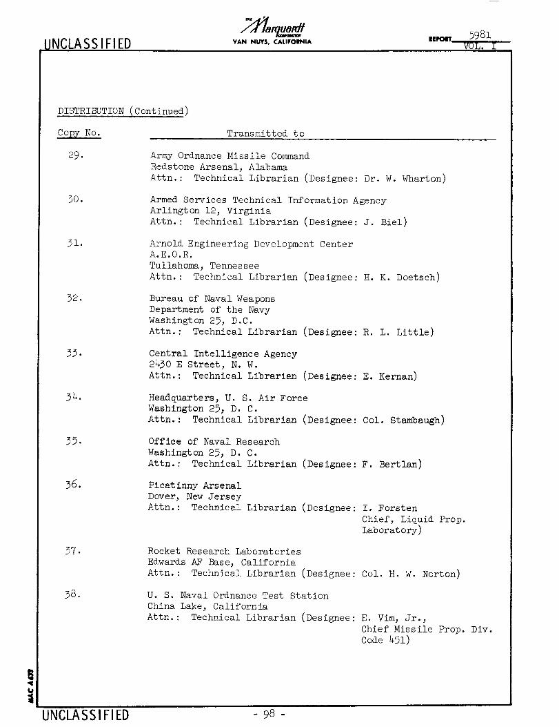
NCLASSIFIED VAN NUY$, CALIFOIBNIA .,o,,
DISTRIBUTION (Continued)
Copy No. Transmitted to
29. Army Ordnance Missile Command
Redstone Arsenal, Alabama
Attn.: Technical Librarian (Designee: Dr. W. Wharton)
30. Armed Services Technical Information Agency
Arlington 12, Virginia
Attn.: Technical Librarian (Designee: J. Biel)
31. Arnold Engineering Development Center
A.E.O.R.
Tullahoma, Tennessee
Attn. : Technical Librarian (Designee: H. K. Doetsch)
32. Bureau of Naval Weapons
Department of the Navy
Washington 25, D.C.
Attn.: Technical Librarian (Designee: R. L. Little)
33. Central Intelligence Agency
2430 E Street, N. W.
Attn.: Technical Librarian (Designee: E. Kernan)
34. Headquarters, U. S. Air Force
Washington 25, D. C.
Attn. : Technical Librarian (Designee: Col. Stambaugh)
35.
36.
Office of Naval Research
Washington 25, D. C.
Attn.: Technical Librarian (Designee: F. Bertlan)
Picatlnny Arsenal
Dover, New Jersey
Attn.: Technical Librarian (Designee: I. Forsten
Chief, Liquid Prop.
Laboratory)
37. Rocket Research Laboratories
Edwards AF Base, California
Attn.: Technical Librarian (Designee: Col. H. W. Norton)
38. U. S. Naval Ordnance Test Station
China Lake, California
Attn.: Technical Librarian (Designee: E. Vim, Jr.,
Chief Missile Prop. Div.
Code 451)
UNCLASSIFIED - 98 -
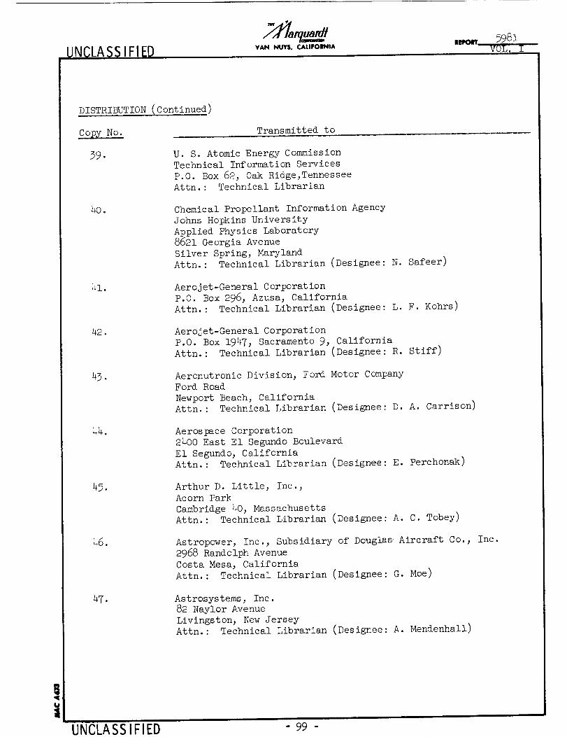
_UNCLASS IFIED VAN NUVS, CALIFOIINIA
DISTRIBUTION (Continued)
Copy No. Transmitted to
39. U. S. Atomic Energy CommissionTechnical Information Services
P.O. Box 62, Oak Ridge,Tennessee
Attn.: Technical Librarian
40. Chemical Propellant Information Agency
Johns Hopkins University
Applied Physics Laboratory
8621 Georgia Avenue
Silver Spring, Maryland
Attn.: Technical Librarian (Designee: N. Safeer)
41. Aerojet-General Corporation
P.O. Box 296, Azusa, California
Attn.: Technical Librarian (Designee: L. F. Kohrs)
42. Aerojet-General Corporation
P.O. Box 1947, Sacramento 9, California
Attn.: Technical Librarian (Designee: R. Stiff)
43. Aeronutronic Division, Ford Motor Company
Ford Road
Newport Beach, California
Attn.: Technical Librarian (Designee: D. A. Carrison)
44. Aerospace Corporation
2400 East E1 Segundo Boulevard
E1 Segundo; California
Attn.: Technical Librarian (Designee: E. Perchonak)
45. Arthur D. Little, Inc._
Acorn Park
Cambridge 4% Massachusetts
Attn.: Technical Librarian (Designee: A. C. Tobey)
46. Astropower, Inc., Subsidiary of Douglas Aircraft Co., Inc.
2968 Randolph Avenue
Costa Mesa, California
Attn.: Technical Librarian (Designee: G. Moe)
47. Astrosystems, Inc.
82 Naylor Avenue
Livingston_ New Jersey
Attn.: Technical Librarian (Designee: A. Mendenhall)
UNCLASSIFIED - 99 -
NCLASSIFIED VAN NUY$, CALIFOINIA IIEFOlTVOL. I
DISTRII_JTION (Continued)
Copy No. Transmitted to
48. Atlantic Research Corporation
Edsall Road and Shirley Highway
Alexandria, Virginia
Attn.: Technical Librarian (Designee: A. Scarlock)
_9. Beech Aircraft Corporation
Boulder Facility
P.O. Box 631, Boulder, Colorado
Attn.: Technical Librarian (Designee: J. H. Rodgers)
_O. Bell Aerosystems Company
P. 0. Box i, Buffalo 5, New York
Attn.: Technical Librarian (Designee: W. M. Smith)
51. Bendix Systems Division
Bendix Corporation
Ann Arbor, Michigan
Attn.: Technical Librarian (Designee: J. M. Brueger)
52. Boeing Company
P.O. Box 3707, Seattle 24, Washington
Attn. : Technical Librarian (Designee: J. D. Alexander)
3. Convair/Astronautics
P.O. Box 2672, San Diego 12, California
Attn.: Technical Librarian (Designee: F. Dore)
54. Curtiss-Wright Corporation
Wright Aeronautical Division
Wood-Ridge, New Jersey
Attn.: Technical I,ibrarian (Designee: G. Kelley)
55. Douglas Aircraft Company, Inc.
Missile and Space Systems Division
3000 Ocean Park Boulevard
Santa Monica_ California
Attn.: Technical Librarian (Designee: C. J. Dorenbacher)
76. Fairchild Stratos CorporationAircraft Missiles Division
Hagerstown, Maryland
Attn.: Technical Librarian (Designee: J. R. Farrow)
UNCLASS IFIED - loo-
NCLASSIFIED VAN NUYS. CALIFOI_IAIIEPOIIT
5981
VOL. I
DISTRIBUTION (Continued)
Copy No. Transmitted to
57. General Electric Company
Missile and Space Vehicle Department
P.O. Box 855J, Philadelphia, Pennsylvania
Attn.: Technical Librarian (Designee: L. S. Beers)
58. General Electric Company
Rocket Propulsion Units, Bldg. 300
Cincinnati 15, OhioAttn.: Technical Librarian (Designee: D. Suichu)
59. Grumman Aircraft Engineering Corporation
Bethpage, Long Island, New YorkAttn.: Technical Librarian (Designee: J. Gavin)
60. Walter Kidde and Company_ Inc.
Kidde Aerospace Division
675 Main Street
Belleville 9, New JerseyAttn.: Technical Librarian (Designee: J. Marcinek)
61. Lockheed Aircraft Corporation
Missile and Space Division
Sunnyvale_ CaliforniaAttn.: Technical Librarian (Designee: H. Zwemer)
62. Lockheed Propulsion Company
P.O. Box iii, Redlands, CaliforniaAttn.: Technical Librarian (Designee: H. L. Thockwell)
62. Martin-Marietta Corporation
Martin Division
Baltimore 3, MarylandAttn.: Technical Librarian (Designee: W. P. Sommers)
64. Martin-Marietta Corporation
Martin Denver Division
Denver, ColoradoAttn.: Technical Librarian (Designee: J. D. Goodletti, A-241)
65. McDonnell Aircraft Corporation
P.O. Box 6101, Lambert Field, Missouri
Attn.: Technical Librarian (Designee: R. A. Herzmark)
JNCLASSIFIED - lOl-
UNCLASSIFIEDIEPOIT, 5981
yOL. I
DISTRII_JTiON (Continued)
Copy No. Transmitted to
66. North American Aviation, Inc.
Space and Information Syste_ Division
Downey, California
Attn.: Technical Librarian (Desi_lee: H. Storms)
67. Northrop Corporation
I001 East Broadway
Hawthorne, California
Attn.: Technical Librarian (Designee: W. E. Gasich)
68. Pratt and Whitney Aircraft Corporation
Florida Research and Development Center
West Palm Beach, Florida
Attn.: Technical Librarian (Designee: R. J. Coar)
69. Radio Corporation of America
Astro-Electronics Division
Defense Electronics Products
Princeton, New Jersey
Attn.: Technical Librarian (Designee: S. Fairweather)
70. Thiokol Chemical Corporation
Reaction Motors Division
Denville_ New Jersey
Attn.: Technical Librarian (Designee: A. Sherman)
71. Republic Aviation Corporation
Farmingdale, Long Island, New York
Attn. : Technical Librarian (Designee: W. 0'Donnell)
72. Rocketdyne Division
North American Aviation_ Inc.
6633 Canoga Avenue
Canoga Park, California
Attn.: Technical Librarian (Designee: E. B. Monteath)
73. Space-General Corporation
9200 Flair Avenue
E1 Monte, California
Attno: Technical Librarian (Designee: C. E. Roth)
74. Space Technology Laboratories
P.O. Box 95001, Airport Station
Los Angeles 49, California
Attn.: Technical Librarian (Designee: G. W. Elverum)
!
UNCLASSIFIED - lO2-
UNCLASS IFIED VAN NUYS, CALIFOItNIAmE_ 5981
VOL. I
!
DISTRIBUTION (Continued)
Copy No. Transmitted to
75. Stanford Research Institute
333 Ravenswood Avenue
Menlo Park, CaliforniaAttn.: Technical Librarian (Designee: T. Smith)
76. Thompson-Ramo-Wooldridge_ Inc.
Tapco Division
23555 Euclid Avenue
Cleveland 17, Ohio
Attn.: Technical Librarian (Designee: P. T. Angell)
77. Thiokol Chemical Corporation
Redst one Division
Huntsville, Alabama
Attn. : Technical Librarian (Designee: W. L. Berry)
78. United Aircraft Corporation
East Hartford Plant
400 Main Street
Hartford, Connecticut
Attn.: Technical Librarian (Designee: E. Martin)
79. United Technology Corporation
587 Mathilda Avenue
Sunnyvale_ CaliforniaAttn.: Technical Librarian (Designee: B. Abelman)
80° Vought Astronautics
P.O. Box 4907, Dallas 22, Texas
Attn.: Technical Librarian (Designee: W. C. Trent)
UNCLASS IFIED - i03 -


Related Documents