474 http://www.pisco.co.jp Quick Exhaust Valve Series Exhaust Valve Series Fixed orifice Series Pressure Controller Series Pressure Gauge Series Check Valve Series Silencer Series Anti-spatter Series TUBE VALVE CONTROLLER MAKE-TO-ORDER PRODUCTS Push-In Fitting Type Flow Control Valve for Sparks Condition Throttle (Needle) Valve Brass Series ● Control Actuator Speed and Pneumatic Signals. ● Suitable for High Temp. and Sparks Condition. ● Adjustable Flow Rate during Air Flow. ● Seal Rubber Selection for Various Usage ● Superior in Flame-Retardant and Spatter-Proof by its Brass Made Release-Ring ● Avoid Spatter and Dusts by Protective Cover

Welcome message from author
This document is posted to help you gain knowledge. Please leave a comment to let me know what you think about it! Share it to your friends and learn new things together.
Transcript
474
http://www.pisco.co.jp
Quick ExhaustValve Series
ExhaustValve Series
Fixed orificeSeries
Pressure ControllerSeries
Pressure GaugeSeries
Check ValveSeries
SilencerSeries
Anti-spatterSeries
TUBE
VALVE
CONTROLLERMAKE-TO-ORDERPRODUCTS
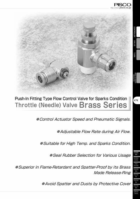
Push-In Fitting Type Flow Control Valve for Sparks ConditionThrottle (Needle) Valve Brass Series
●Control Actuator Speed and Pneumatic Signals.
●Suitable for High Temp. and Sparks Condition.
●Adjustable Flow Rate during Air Flow.
●Seal Rubber Selection for Various Usage
●Superior in Flame-Retardant and Spatter-Proof by its Brass Made Release-Ring
●Avoid Spatter and Dusts by Protective Cover
Controller SeriesThrottle (Needle) Valve Brass
475
Anti-spatterSeries
PPSeries
StainlessSeries
Throttle (Needle)Valve Series
Constant FlowSeries
PPSeries
Anti-spatterSeries
StainlessSeries
Speed ControllerSeries
CONT
ROLL
ERFI
TTIN
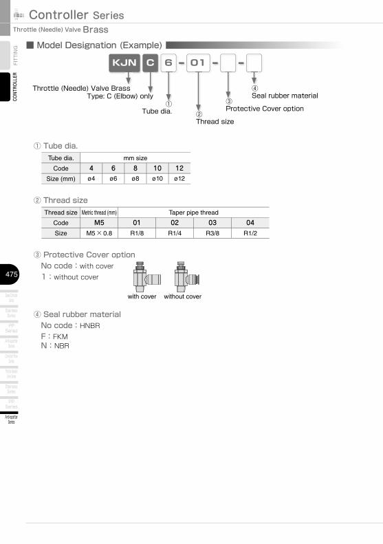
G ■ Model Designation (Example)
CKJN 6 01
① Tube dia.
② Thread sizeThread size Metric thread (mm) Taper pipe thread
Code M5 01 02 03 04Size M5×0.8 R1/8 R1/4 R3/8 R1/2
Tube dia. mm size
Code 4 6 8 10 12Size (mm) ø4 ø6 ø8 ø10 ø12
Throttle (Needle) Valve BrassType: C (Elbow) only
②Thread size
①Tube dia.
③Protective Cover option
④Seal rubber material
③ Protective Cover option No code:with cover 1:without cover
④ Seal rubber material No code:HNBR F:FKM N:NBR
with cover without cover
476
http://www.pisco.co.jp
Quick ExhaustValve Series
ExhaustValve Series
Fixed orificeSeries
Pressure ControllerSeries
Pressure GaugeSeries
Check ValveSeries
SilencerSeries
Anti-spatterSeries
TUBE
VALVE
CONTROLLERMAKE-TO-ORDERPRODUCTS
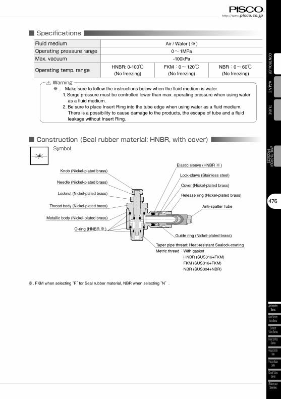
■ SpecificationsFluid medium Air / Water (※ )
Operating pressure range 0~1MPa
Max. vacuum -100kPa
Operating temp. range HNBR: 0-100℃(No freezing)
FKM:0~120℃(No freezing)
NBR:0~60℃(No freezing)
■ Construction (Seal rubber material: HNBR, with cover)
Elastic sleeve (HNBR ※ )
Taper pipe thread: Heat-resistant Sealock-coating
Metric thread:With gasket
HNBR (SUS316+FKM)
FKM (SUS316+FKM)
NBR (SUS304+NBR)
Anti-spatter Tube
Release ring (Nickel-plated brass)
Lock-claws (Stainless steel)
O-ring (HNBR ※ )
Metallic body (Nickel-plated brass)
Guide ring (Nickel-plated brass)
Locknut (Nickel-plated brass)
Symbol
Needle (Nickel-plated brass)
※ . Make sure to follow the instructions below when the fluid medium is water. 1. Surge pressure must be controlled lower than max. operating pressure when using water
as a fluid medium. 2. Be sure to place Insert Ring into the tube edge when using water as a fluid medium.
There is a possibility to cause damage to the products, the escape of tube and a fluid leakage without Insert Ring.
Warning
Knob (Nickel-plated brass)
Thread body (Nickel-plated brass)
Cover (Nickel-plated brass)
※ . FKM when selecting “F” for Seal rubber material, NBR when selecting “N” .

Controller SeriesThrottle (Needle) Valve Brass
477
Anti-spatterSeries
PPSeries
StainlessSeries
Throttle (Needle)Valve Series
Constant FlowSeries
PPSeries
Anti-spatterSeries
StainlessSeries
Speed ControllerSeries
CONTROLLER
FITTING Detailed Safety Instructions
Before using PISCO products, be sure to read “Safety Instructions” and “Safety Instruction Manual” on page 23 to 27 and “Common Safety Instructions for Controllers” on page 367 to 368.
Warning1. When controlling the speed of actuators, slowly release the air by adjusting the needle
from a fully closed state. In case the needle is opened, actuator can move suddenly. Turn needle in the clockwise direction to close, and in the counterclockwise to open.
2. Slowly turn the needle to release air from a fully closed state, when adjusting air flow. In case large amount of air is supplied in a sudden when the needle is an opened state, the machine may be damaged by the air.
3. Be sure to place Insert Ring into the tube edge when the fluid medium is liquid. There is a possibility to cause the escape of tube and a fluid leakage without Insert Ring.
4. Surge pressure must be controlled lower than max. operating pressure when using water or liquid as a fluid medium.
5. Metallic body is rotatable, but do not swing and rotate it by force or continuously. It may cause damage to the products and a fluid leakage.
6. Select seal rubber material considering sufficient margin to the operating temperature range. Seal rubber material can be worn out by heat and may cause a fluid leakage. Perform maintenance periodically and in case leaks are found, replace the product to the new one promptly.
7. Throttle (Needle) Valve Brass series has seal rubber material options, but there is no way to identify between each material by seal rubber. Store each product properly not to mix up after opening their packages.
■ Applicable Tube and Related ProductsAnti-spatter Tube………P.646Tube Fitting Anti-spatter Series…………P.204Tube Fitting Brass Series…………P.212Speed Controller Anti-spatter Series…………P.422Speed Controller Brass Series…………P.430
Caution1. Throttle (Needle) valve permits some air leakage. Do not use the products for the
application which requires no leakage.2. When using Anti-spatter Tube, peel the cover as the following table shows. It may cause
the escape of a tube, a fluid leakage or even impossible to insert the tube into Push-In Fitting, if the tube is not peeled properly.
Tube dia. ø4mm ø6mm ø8mm ø10mm ø12mm
Peeled length(C) 15mm 16mm 17mm 19.5mm 23mm
CAnti-spatter Tube
478
http://www.pisco.co.jp
Quick ExhaustValve Series
ExhaustValve Series
Fixed orificeSeries
Pressure ControllerSeries
Pressure GaugeSeries
Check ValveSeries
SilencerSeries
Anti-spatterSeries
TUBE
VALVE
CONTROLLERMAKE-TO-ORDERPRODUCTS
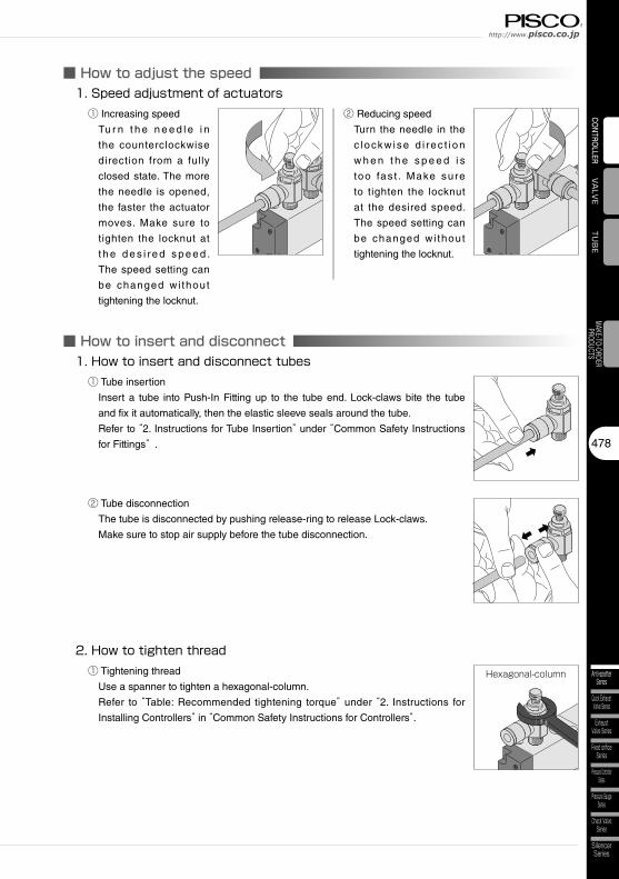
■ How to insert and disconnect1. How to insert and disconnect tubes
① Tube insertion
Insert a tube into Push-In Fitting up to the tube end. Lock-claws bite the tube
and fix it automatically, then the elastic sleeve seals around the tube.
Refer to “2. Instructions for Tube Insertion” under “Common Safety Instructions
for Fittings” .
② Tube disconnection
The tube is disconnected by pushing release-ring to release Lock-claws.
Make sure to stop air supply before the tube disconnection.
2. How to tighten thread① Tightening thread
Use a spanner to tighten a hexagonal-column.
Refer to “Table: Recommended tightening torque” under “2. Instructions for
Installing Controllers” in “Common Safety Instructions for Controllers”.
Hexagonal-column
■ How to adjust the speed1. Speed adjustment of actuators
① Increasing speed
Tu r n t h e n e e d l e i n
the counterclockwise
direction from a fully
closed state. The more
the needle is opened,
the faster the actuator
moves. Make sure to
tighten the locknut at
t h e d e s i re d s p e e d .
The speed setting can
be changed wi thout
tightening the locknut.
② Reducing speed
Turn the needle in the
c lockw ise d i rec t i on
w h e n t h e s p e e d i s
too fas t . Make sure
to tighten the locknut
at the desired speed.
The speed setting can
be changed wi thout
tightening the locknut.

Controller SeriesThrottle (Needle) Valve Brass
479
Anti-spatterSeries
PPSeries
StainlessSeries
Throttle (Needle)Valve Series
Constant FlowSeries
PPSeries
Anti-spatterSeries
StainlessSeries
Speed ControllerSeries
CONT
ROLL
ERFI
TTIN
G
CAD data is available at PISCO website.CAD ChartP.000 Characteristic chart page
KJNC
Unit:mm
Model codeTube O.D.øD1
Tube O.D.øD2 R A
B L1L2 E C1 C2 øP1 øP2 øK1 øK2 Hex.
HWeight(g)max. min. max. min.
KJNC4-M5-□4 6
M5×0.8 3 32.7 30 29.7 27 8.1 22.617.6 15 12.5
12 5 8 11 26.2
KJNC4-01-□ R1/8 8 44.4 38.3 40.4 34.3 11.6 24.8 16 8 10 14 44.4
KJNC6-M5-□
6 8
M5×0.8 3 32.7 30 29.7 27 8.1 24.1
19.5 1612.5
12 5 8 11 26.6
KJNC6-01-□ R1/8 8 44.4 38.3 40.4 34.3 11.6 26.1 16 8 10 14 44.7
KJNC6-02-□ R1/4 11.1 53.6 46.8 47.6 40.8 15 27.614.5
19 10 13 17 71.5
KJNC6-03-□ R3/8 12.1 59.5 51.5 53.1 45.1 16.8 29.3 22.5 12 16 21 112.4
KJNC8-01-□8 10
R1/8 8 44.4 38.3 40.4 34.3 11.6 26.920.2 17 14.5
16 8 10 14 47.1
KJNC8-02-□ R1/4 11.1 53.6 46.8 47.6 40.8 15 28.4 19 10 13 17 71.7
KJNC8-03-□ R3/8 12.1 59.5 51.5 53.1 45.1 16.8 30.1 22.5 12 16 21 112.3
KJNC10-02-□10 12
R1/4 11.1 53.6 46.8 47.6 40.8 15 31.223.2 19.5
18.6 19 10 13 17 85
KJNC10-03-□ R3/8 12.1 59.5 51.5 53.1 45.1 16.8 3321.5
22.5 1216
21 133.6
KJNC10-04-□ R1/2 13.8 63.2 56 55 47.8 17.6 35.5 27.5 13 27 193.7
KJNC12-03-□12 14
R3/8 12.1 59.5 51.5 53.1 45.1 16.8 36.126.3 23 21.6
22.5 1216
21 139.9
KJNC12-04-□ R1/2 13.8 63.2 56 55 47.8 17.6 36.6 27.5 13 27 200.3
※ “L1” and “L2” are reference values for height dimensions after tightening taper thread.
※ □ in Model code / Replaced with “F” (FKM), or “N” (NBR) for Seal rubber material change
øK2øK1 E
C1C2
H
RøP2
øP
1ø
D2
øD
1
AL2
L1B
øK2øK1 E
C1C2
RøP2
H
øP
1ø
D2
øD
1
0.5
AL2
L1B
Metric thread type Taper pipe thread type
Elbow ChartP.481
compliant

480
http://www.pisco.co.jp
Quick ExhaustValve Series
ExhaustValve Series
Fixed orificeSeries
Pressure ControllerSeries
Pressure GaugeSeries
Check ValveSeries
SilencerSeries
Anti-spatterSeries
TUB
EVA
LVECONTROLLER
MAKE-TO-ORDERPRODUCTS
CAD data is available at PISCO website.CAD ChartP.000 Characteristic chart page
Unit:mm
Model codeTube O.D.
øD R AB L1
L2 E C øP1 øP2 øK1 øK2 Hex.H
Weight(g)max. min. max. min.
KJNC4-M5-1-□4
M5×0.8 3 32.7 30 29.7 27 8.1 19.714.5 12.5
12 5 8 11 24.6
KJNC4-01-1-□ R1/8 8 44.4 38.3 40.4 34.3 11.6 21.7 16 8 10 14 42.7
KJNC6-M5-1-□
6
M5×0.8 3 32.7 30 29.7 27 8.1 21.2
16.612.5
12 5 8 11 24.9
KJNC6-01-1-□ R1/8 8 44.4 38.3 40.4 34.3 11.6 23.2 16 8 10 14 43
KJNC6-02-1-□ R1/4 11.1 53.6 46.8 47.6 40.8 15 24.714.5
19 10 13 17 69.7
KJNC6-03-1-□ R3/8 12.1 59.5 51.5 53.1 45.1 16.8 26.4 22.5 12 16 21 110.6
KJNC8-01-1-□8
R1/8 8 44.4 38.3 40.4 34.3 11.6 24.417.7 14.5
16 8 10 14 45.2
KJNC8-02-1-□ R1/4 11.1 53.6 46.8 47.6 40.8 15 25.9 19 10 13 17 69.8
KJNC8-03-1-□ R3/8 12.1 59.5 51.5 53.1 45.1 16.8 27.6 22.5 12 16 21 110.4
KJNC10-02-1-□10
R1/4 11.1 53.6 46.8 47.6 40.8 15 2820
18.5 19 10 13 17 80.1
KJNC10-03-1-□ R3/8 12.1 59.5 51.5 53.1 45.1 16.8 29.821.5
22.5 1216
21 128.7
KJNC10-04-1-□ R1/2 13.8 63.2 56 55 47.8 17.6 32.3 27.5 13 27 188.8
KJNC12-03-1-□12
R3/8 12.1 59.5 51.5 53.1 45.1 16.8 32.422.6 21.5
22.5 1216
21 132.4
KJNC12-04-1-□ R1/2 13.8 63.2 56 55 47.8 17.6 34.9 27.5 13 27 192.8
※ “L1” and “L2” are reference values for height dimensions after tightening taper thread.
※ □ in Model code / Replaced with “F” (FKM), or “N” (NBR) for Seal rubber material change
øK2øK1 E
C
RøP2
H
øD
øP
1
A0.
5L2
L1B
øK2øK1 E
CH
RøP2
øP
1ø
D
AL2
L1B
Metric thread type Taper pipe thread type
Elbow without cover ChartP.481KJNC
NO COVER
compliant
Controller SeriesThrottle (Needle) Valve Brass
481
Anti-spatterSeries
PPSeries
StainlessSeries
Throttle (Needle)Valve Series
Constant FlowSeries
PPSeries
Anti-spatterSeries
StainlessSeries
Speed ControllerSeries
CONTROLLER
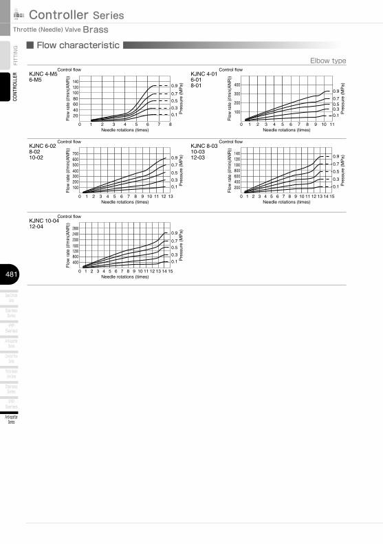
FITTING ■ Flow characteristic
Elbow type
0
20406080100120140
1 2 3 4 5 6 7 8
0.7
0.9
0.5
0.3
0.1
Needle rotations (times)
Flo
w r
ate
(l/m
in(A
NR
))Control flow
Pre
ssur
e (M
Pa)
KJNC 4-M56-M5
0
100
200
300
400
1 2 3 4 5 6 7 8 9 10 11
0.7
0.9
0.50.30.1
Needle rotations (times)
Flo
w r
ate
(l/m
in(A
NR
))
Control flow
Pre
ssur
e (M
Pa)
KJNC 4-016-018-01
0
500400300200100
600700
1 2 3 4 5 6 7 8 9 10 11 12 13
0.7
0.9
0.5
0.3
0.1
Needle rotations (times)
Flo
w r
ate
(l/m
in(A
NR
))
Control flow
Pre
ssur
e (M
Pa)
KJNC 6-028-0210-02
0
200400600800
140012001000
1 2 3 4 5 6 7 8 9 10 11 12 13 14 15
1 2 3 4 5 6 7 8 9 10 11 12 13 14 15
0.7
0.9
0.5
0.3
0.1
Needle rotations (times)
Flo
w r
ate
(l/m
in(A
NR
))
Control flow
Pre
ssur
e (M
Pa)
KJNC 8-0310-0312-03
0
400800
2800
1200160020002400
0.7
0.9
0.5
0.3
0.1
Needle rotations (times)
Flo
w r
ate
(l/m
in(A
NR
))
Control flow
Pre
ssur
e (M
Pa)
KJNC 10-0412-04

23
Safety Instructions
SAFETY Instructions
Warning
This safety instructions aim to prevent personal injury and damage to properties by requiring proper use of PISCO products. Be certain to follow ISO 4414 and JIS B 8370
ISO 4414:Pneumatic fluid power…Recomendations for the application of equipment to transmission and control systems.
JIS B 8370:General rules and safety requirements for systems and their components.This safety instructions is classified into “Danger”, “Warning” and “Caution” depending on the degree of danger or damages caused by improper use of PISCO products.
1. Selection of pneumatic products① A user who is a pneumatic system designer or has sufficient experience
and technical expertise should select PISCO products.② Due to wide variety of operating conditions and applications for PISCO
products, carry out the analysis and evaluation on PISCO products. The pneumatic system designer is solely responsible for assuring that the user's requirements are met and that the application presents no health or safety hazards. All designers are required to fully understand the specifications of PISCO products and constitute all systems based on the latest catalog or information, considering any malfunctions.
2. Handle the pneumatic equipment with enough knowledge and experience① Improper use of compressed air is dangerous. Assembly, operation
and maintenance of machines using pneumatic equipment should be conducted by a person with enough knowledge and experience.
3. Do not operate machine / equipment or remove pneumatic equipment until safety is confirmed.① Make sure that preventive measures against falling work-pieces or
sudden movements of machine are completed before inspection or maintenance of these machine.
② Make sure the above preventive measures are completed. A compressed air supply and the power supply to the machine must be off, and also the compressed air in the systems must be exhausted.
③ Restart the machines with care after ensuring to take all preventive measures against sudden movements.
Danger Hazardous conditions. It can cause death or serious personal injury.
Warning Hazardous conditions depending on usages. Improper use of PISCO products can cause death or serious personal injury.
Caution Hazardous conditions depending on usages. Improper use of PISCO products can cause personal injury or damages to properties.
※ . This safety instructions are subject to change without notice.
http://www.pisco.co.jphttp://www.pisco.co.jp
24
Disclaimer1. PISCO does not take any responsibility for any incidental or indirect
loss, such as production line stop, interruption of business, loss of benefits, personal injury, etc., caused by any failure on use or application of PISCO products.
2. PISCO does not take any responsibility for any loss caused by natural disasters, fires not related to PISCO products, acts by third parties, and intentional or accidental damages of PISCO products due to incorrect usage.
3. PISCO does not take any responsibility for any loss caused by improper usage of PISCO products such as exceeding the specification limit or not following the usage the published instructions and catalog allow.
4. PISCO does not take any responsibility for any loss caused by remodeling of PISCO products, or by combinational use with non-PISCO products and other software systems.
5. The damages caused by the defect of Pisco products shall be covered but limited to the full amount of the PISCO products paid by the customer.
25
Safety Instructions
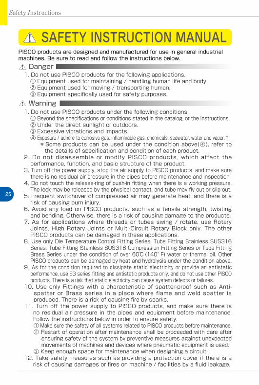
SAFETY INSTRUCTION MANUAL
Danger1. Do not use PISCO products for the following applications.
① Equipment used for maintaining / handling human life and body.② Equipment used for moving / transporting human.③ Equipment specifically used for safety purposes.
Warning1. Do not use PISCO products under the following conditions.
① Beyond the specifications or conditions stated in the catalog, or the instructions.② Under the direct sunlight or outdoors.③ Excessive vibrations and impacts.④ Exposure / adhere to corrosive gas, inflammable gas, chemicals, seawater, water and vapor. *
* Some products can be used under the condition above(④), refer to the details of specification and condition of each product.
2. Do not disassemble or modify PISCO products, which affect the performance, function, and basic structure of the product.
3. Turn off the power supply, stop the air supply to PISCO products, and make sure there is no residual air pressure in the pipes before maintenance and inspection.
4. Do not touch the release-ring of push-in fitting when there is a working pressure. The lock may be released by the physical contact, and tube may fly out or slip out.
5. Frequent switchover of compressed air may generate heat, and there is a risk of causing burn injury.
6. Avoid any load on PISCO products, such as a tensile strength, twisting and bending. Otherwise, there is a risk of causing damage to the products.
7. As for applications where threads or tubes swing / rotate, use Rotary Joints, High Rotary Joints or Multi-Circuit Rotary Block only. The other PISCO products can be damaged in these applications.
8. Use only Die Temperature Control Fitting Series, Tube Fitting Stainless SUS316 Series, Tube Fitting Stainless SUS316 Compression Fitting Series or Tube Fitting Brass Series under the condition of over 60℃ (140°F) water or thermal oil. Other PISCO products can be damaged by heat and hydrolysis under the condition above.
9. As for the condition required to dissipate static electricity or provide an antistatic performance, use EG series fitting and antistatic products only, and do not use other PISCO products. There is a risk that static electricity can cause system defects or failures.
10. Use only Fittings with a characteristic of spatter-proof such as Anti-spatter or Brass series in a place where flame and weld spatter is produced. There is a risk of causing fire by sparks.
11. Turn off the power supply to PISCO products, and make sure there is no residual air pressure in the pipes and equipment before maintenance. Follow the instructions below in order to ensure safety.① Make sure the safety of all systems related to PISCO products before maintenance.② Restart of operation after maintenance shall be proceeded with care after
ensuring safety of the system by preventive measures against unexpected movements of machines and devices where pneumatic equipment is used.
③ Keep enough space for maintenance when designing a circuit.12. Take safety measures such as providing a protection cover if there is a
risk of causing damages or fires on machine / facilities by a fluid leakage.
PISCO products are designed and manufactured for use in general industrial machines. Be sure to read and follow the instructions below.

http://www.pisco.co.jphttp://www.pisco.co.jp
26
Caution1. Remove dusts or drain before piping. They may get into the peripheral
machine / facilities and cause malfunction.2. When inserting an ultra-soft tube into push-in fitting, make sure to place
an Insert Ring into the tube edge. There is a risk of causing the escape of tube and a fluid leakage without using an Insert Ring.
3. The product incorporating NBR as seal rubber material has a risk of malfunction caused by ozone crack. Ozone exists in high concentrations in static elimination air, clean-room, and near the high-voltage motors, etc. As a countermeasure, material change from NBR to HNBR or FKM is necessary. Consult with PISCO for more information.
4. Special option “Oil-free” products may cause a very small amount of a fluid leakage. When a fluid medium is liquid or the products are required to be used in harsh environments, contact us for further information.
5. In case of using non-PISCO brand tubes, make sure the tolerance of the outer tube diameter is within the limits of Table 1.
●Table 1. Tube O.D. Tolerancemm size Nylon tube Polyurethane tube inch size Nylon tube Polyurethane tubeø1.8mm ─ ±0.05mm ø1/8 ±0.1mm ±0.15mmø3mm ─ ±0.15mm ø5/32 ±0.1mm ±0.15mmø4mm ±0.1mm ±0.15mm ø3/16 ±0.1mm ±0.15mmø6mm ±0.1mm ±0.15mm ø1/4 ±0.1mm ±0.15mmø8mm ±0.1mm ±0.15mm ø5/16 ±0.1mm ±0.15mmø10mm ±0.1mm ±0.15mm ø3/8 ±0.1mm ±0.15mmø12mm ±0.1mm ±0.15mm ø1/2 ±0.1mm ±0.15mmø16mm ±0.1mm ±0.15mm ø5/8 ±0.1mm ±0.15mm
6. Instructions for Tube Insertion① Make sure that the cut end surface of the tube is at right angle without
a scratch on the surface and deformations.② When inserting a tube, the tube needs to be inserted fully into the push-
in fitting until the tubing edge touches the tube end of the fitting as shown in the figure below. Otherwise, there is a risk of leakage.
Tube end
Sealing
Tube is not fully inserted up to tube end.
③ After inserting the tube, make sure it is inserted properly and not to be disconnected by pulling it moderately.
※. When inserting tubes, Lock-claws may be hardly visible in the hole, observed from the front face of the release-ring. But it does not mean the tube will surely escape. Major causes of the tube escape are the followings; ①Shear drop of the lock-claws edge②The problem of tube diameter (usually small)Therefore, follow the above instructions from ① to ③, even lock-claws is hardly visible.

27
7. Instructions for Tube Disconnection① Make sure there is no air pressure inside of the tube, before disconnecting it.② Push the release-ring of the push-in fitting evenly and deeply enough to
pull out the tube toward oneself. By insufficient pushing of the release-ring, the tube may not be pulled out or damaged by scratch, and tube shavings may remain inside of the fitting, which may cause the leakage later.
8. Instructions for Installing a fitting① When installing a fitting, use proper tools to tighten a hexagonal-column
or an inner hexagonal socket. When inserting a hex key into the inner hexagonal socket of the fitting, be careful so that the tool does not touch lock-claws. The deformation of lock-claws may result in a poor performance of systems or an escape of the tube.
② Refer to Table 2 which shows the recommended tightening torque. Do not exceed these limits to tighten a thread. Excessive tightening may break the thread part or deform the gasket and cause a fluid leakage. Tightening thread with tightening torque lower than these limits may cause a loosened thread or a fluid leakage.
③ Adjust the tube direction while tightening thread within these limits, since some PISCO products are not rotatable after the installation.
●Table 2: Recommended tightening torque / Sealock color / Gasket materialsThread type Thread size Tightening torque Sealock color Gasket materials
Metric thread
M3×0.5 0.7N·m
─
SUS304NBR
M5×0.8 1.0 ~ 1.5N·mM6×1 2 ~ 2.7N·m
M3×0.5 0.5 ~ 0.6N·m
POMM5×0.8 1 ~ 1.5N·mM6×0.75 0.8 ~ 1N·mM8×0.75 1 ~ 2N·m
Taper pipe thread
R1/8 7 ~ 9N·m
White ─R1/4 12 ~ 14N·mR3/8 22 ~ 24N·mR1/2 28 ~ 30N·m
Unified thread No.10-32UNF 1.0 ~ 1.5N·m ─ SUS304、NBR
National pipe thread taper
1/16-27NPT 7 ~ 9N·m
White ─1/8-27NPT 7 ~ 9N·m1/4-18NPT 12 ~ 14N·m3/8-18NPT 22 ~ 24N·m1/2-14NPT 28 ~ 30N·m
※ These values may differ for some products. Refer to each specification as well.9. Instructions for removing a fitting
① When removing a fitting, use proper tools to loosen a hexagonal-column or an inner hex bolt.
② Remove the sealant stuck on the mating equipment. The remained sealant may get into the peripheral equipment and cause malfunctions.
10. Arrange piping avoiding any load on fittings and tubes such as twist, tensile, moment load, shaking and physical impact. These may cause damages to fittings, tube deformations, bursting and the escape of tubes.
Safety Instructions
Controller SeriesCONTROLLER
367
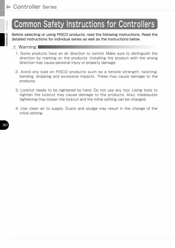
FITTING Common Safety Instructions for Controllers
Warning
Before selecting or using PISCO products, read the following instructions. Read the detailed instructions for individual series as well as the instructions below.
1. Some products have an air direction to control. Make sure to distinguish the direction by marking on the products. Installing the product with the wrong direction may cause personal injury or property damage.
2. Avoid any load on PISCO products such as a tensile strength, twisting, bending, dropping and excessive impacts. These may cause damage to the products.
3. Locknut needs to be tightened by hand. Do not use any tool. Using tools to tighten the locknut may cause damage to the products. Also, inadequate tightening may loosen the locknut and the initial setting can be changed.
4. Use clean air to supply. Dusts and sludge may result in the change of the initial setting.
http://www.pisco.co.jphttp://www.pisco.co.jp
368
Speed ControllerSeries
StainlessSeries
PPSeries
Anti-spatterSeries
Throttle (Needle)Valve Series
StainlessSeries
PPSeries
Quick ExhaustValve Series
ExhaustValve Series
Fixed orificeSeries
Pressure ControllerSeries
Pressure GaugeSeries
Check ValveSeries
SilencerSeries
Constant FlowSeries
Anti-spatterSeries
TUBE
VALVE
CONTROLLERMAKE-TO-ORDERPRODUCTS
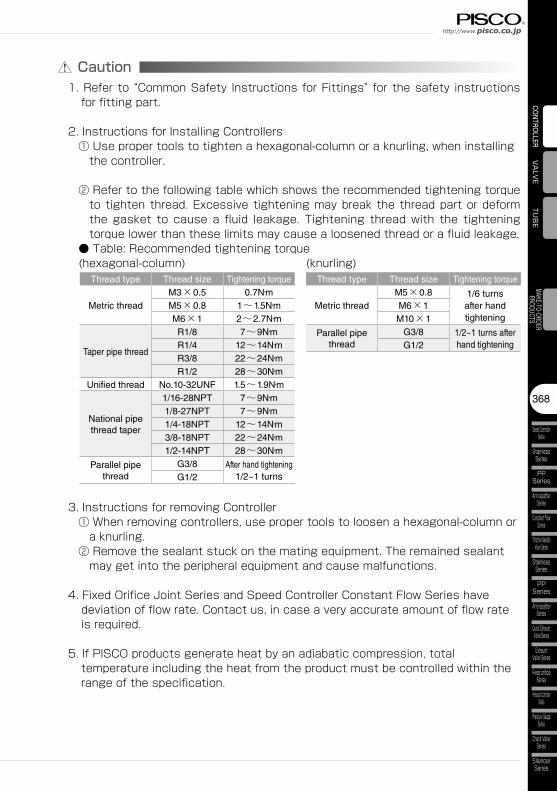
Caution1. Refer to “Common Safety Instructions for Fittings” for the safety instructions
for fitting part.
2. Instructions for Installing Controllers ① Use proper tools to tighten a hexagonal-column or a knurling, when installing
the controller.
② Refer to the following table which shows the recommended tightening torque to tighten thread. Excessive tightening may break the thread part or deform the gasket to cause a fluid leakage. Tightening thread with the tightening torque lower than these limits may cause a loosened thread or a fluid leakage.
● Table: Recommended tightening torque (hexagonal-column) (knurling)
Thread type Thread size Tightening torque Thread type Thread size Tightening torque
Metric thread M3×0.5 0.7N・m
Metric thread M5×0.8 1/6 turns
after hand tightening
M5×0.8 1~1.5N・m M6×1M6×1 2~2.7N・m M10×1
Taper pipe thread
R1/8 7~9N・m Parallel pipe thread
G3/8 1/2~1 turns after hand tighteningR1/4 12~14N・m G1/2
R3/8 22~24N・mR1/2 28~30N・m
Unified thread No.10-32UNF 1.5~1.9N・m
National pipe thread taper
1/16-28NPT 7~9N・m1/8-27NPT 7~9N・m1/4-18NPT 12~14N・m3/8-18NPT 22~24N・m1/2-14NPT 28~30N・m
Parallel pipe thread
G3/8 After hand tightening1/2~1 turnsG1/2
3. Instructions for removing Controller ① When removing controllers, use proper tools to loosen a hexagonal-column or
a knurling. ② Remove the sealant stuck on the mating equipment. The remained sealant
may get into the peripheral equipment and cause malfunctions.
4. Fixed Orifice Joint Series and Speed Controller Constant Flow Series have deviation of flow rate. Contact us, in case a very accurate amount of flow rate is required.
5. If PISCO products generate heat by an adiabatic compression, total temperature including the heat from the product must be controlled within the range of the specification.
Related Documents