1 CHEM-E7195 - Automation systems in Context of Process Systems Engineering – Three tank system Spring 2019 Contents 1 Aim of the work .................................................................................................................................... 1 2 The mixing tank process and its control strategy ................................................................................... 1 2.1 ABB I/O Cabinet ........................................................................................................................... 2 2.2 Three-tank System Connections to ABB Cards .............................................................................. 5 2.2.1 Card AO820 ............................................................................................................................. 6 2.2.2 Card AI801 ............................................................................................................................... 6 2.2.3 Card DO801 ............................................................................................................................. 6 3 Control needs ....................................................................................................................................... 7 3.1 Process limitations ....................................................................................................................... 7 3.2 Process controllers (Minimum requirements): ............................................................................. 7 3.3 Operator needs ............................................................................................................................ 7 4 Documentation ..................................................................................................................................... 7 5 Grading ................................................................................................................................................. 8 1 Aim of the work The aim of this exercise is to familiarize the students to process automation systems and to show how DCS systems are used in large scale environments. In this exercise the student learns to configure a centralized PLC system. 2 The mixing tank process and its control strategy The system consists of three tanks, one reservoir (Main Tank), six control valves, two pumps and three level measurement. The system is connected to ABB system through ABB I/O Cabinet. The Fig. 1 shows the overview of mapping this system.

Welcome message from author
This document is posted to help you gain knowledge. Please leave a comment to let me know what you think about it! Share it to your friends and learn new things together.
Transcript
1
CHEM-E7195-AutomationsystemsinContextofProcessSystemsEngineering–ThreetanksystemSpring2019
Contents1 Aim of the work .................................................................................................................................... 1
2 The mixing tank process and its control strategy ................................................................................... 1
2.1 ABB I/O Cabinet ........................................................................................................................... 2
2.2 Three-tank System Connections to ABB Cards .............................................................................. 5
2.2.1 Card AO820 ............................................................................................................................. 6
2.2.2 Card AI801 ............................................................................................................................... 6
2.2.3 Card DO801 ............................................................................................................................. 6
3 Control needs ....................................................................................................................................... 7
3.1 Process limitations ....................................................................................................................... 7
3.2 Process controllers (Minimum requirements): ............................................................................. 7
3.3 Operator needs ............................................................................................................................ 7
4 Documentation ..................................................................................................................................... 7
5 Grading ................................................................................................................................................. 8
1 AimoftheworkThe aim of this exercise is to familiarize the students to process automation systems and to show how DCS systems are used in large scale environments. In this exercise the student learns to configure a centralized PLC system.
2 ThemixingtankprocessanditscontrolstrategyThe system consists of three tanks, one reservoir (Main Tank), six control valves, two pumps and three level measurement. The system is connected to ABB system through ABB I/O Cabinet. The Fig. 1 shows the overview of mapping this system.
2
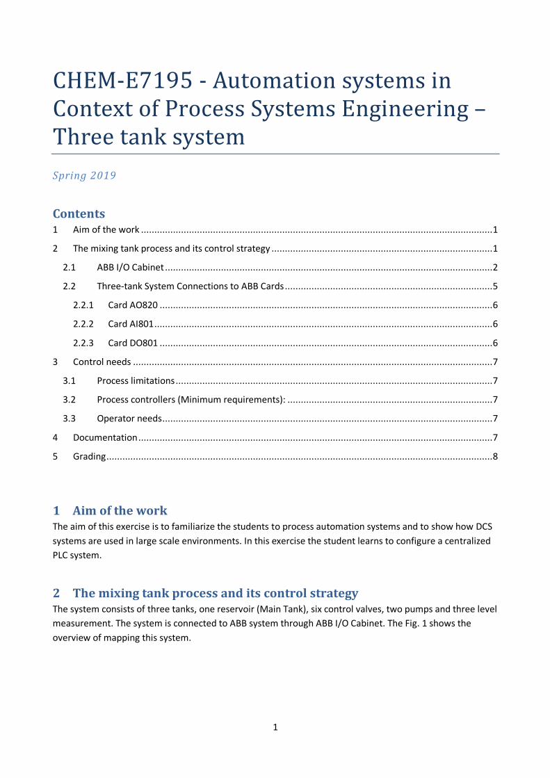
Figure 1. Overview of Three-tank System
Fig. 2 shows the Three-tank System P&ID. In the system GA-101 and GA-102 pump the water from the main reservoir (FA-000) to FA-100 and FA-200 with adjustable flow rates (Analog Signal). Tank FA-100 and FA-300 have a leaking valve and a connecting valve that empties the tank into the FA-000 and connects the tanks to the one next to, respectively. Tank FA-200 has a leaking valve and a drain valve. All the valves of the system have digital actuators (digital signals). Pressure level measurement of each tank sends the level of water back to the ABB I/O card (AI801) as analog signal.
Figure 2. Three-tank System P&ID
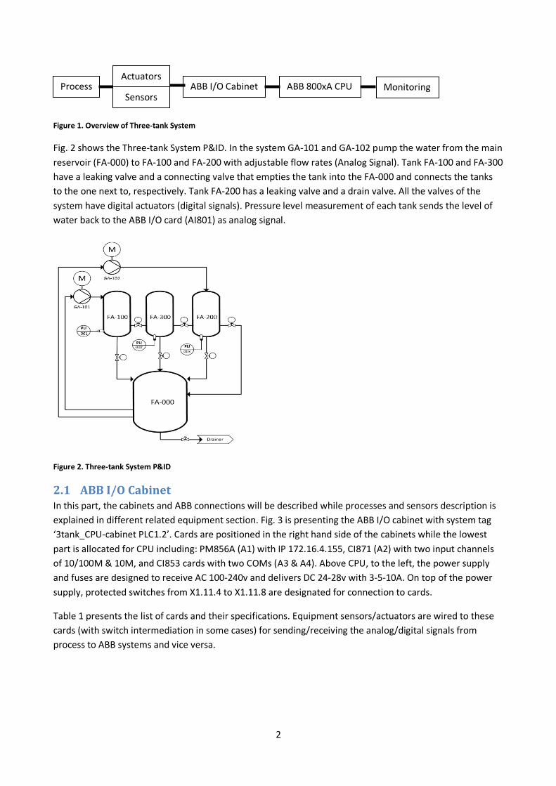
2.1 ABBI/OCabinetIn this part, the cabinets and ABB connections will be described while processes and sensors description is explained in different related equipment section. Fig. 3 is presenting the ABB I/O cabinet with system tag ‘3tank_CPU-cabinet PLC1.2’. Cards are positioned in the right hand side of the cabinets while the lowest part is allocated for CPU including: PM856A (A1) with IP 172.16.4.155, CI871 (A2) with two input channels of 10/100M & 10M, and CI853 cards with two COMs (A3 & A4). Above CPU, to the left, the power supply and fuses are designed to receive AC 100-240v and delivers DC 24-28v with 3-5-10A. On top of the power supply, protected switches from X1.11.4 to X1.11.8 are designated for connection to cards.
Table 1 presents the list of cards and their specifications. Equipment sensors/actuators are wired to these cards (with switch intermediation in some cases) for sending/receiving the analog/digital signals from process to ABB systems and vice versa.
Process ABB I/O Cabinet ABB 800xA CPU Monitoring Sensors
Actuators
3
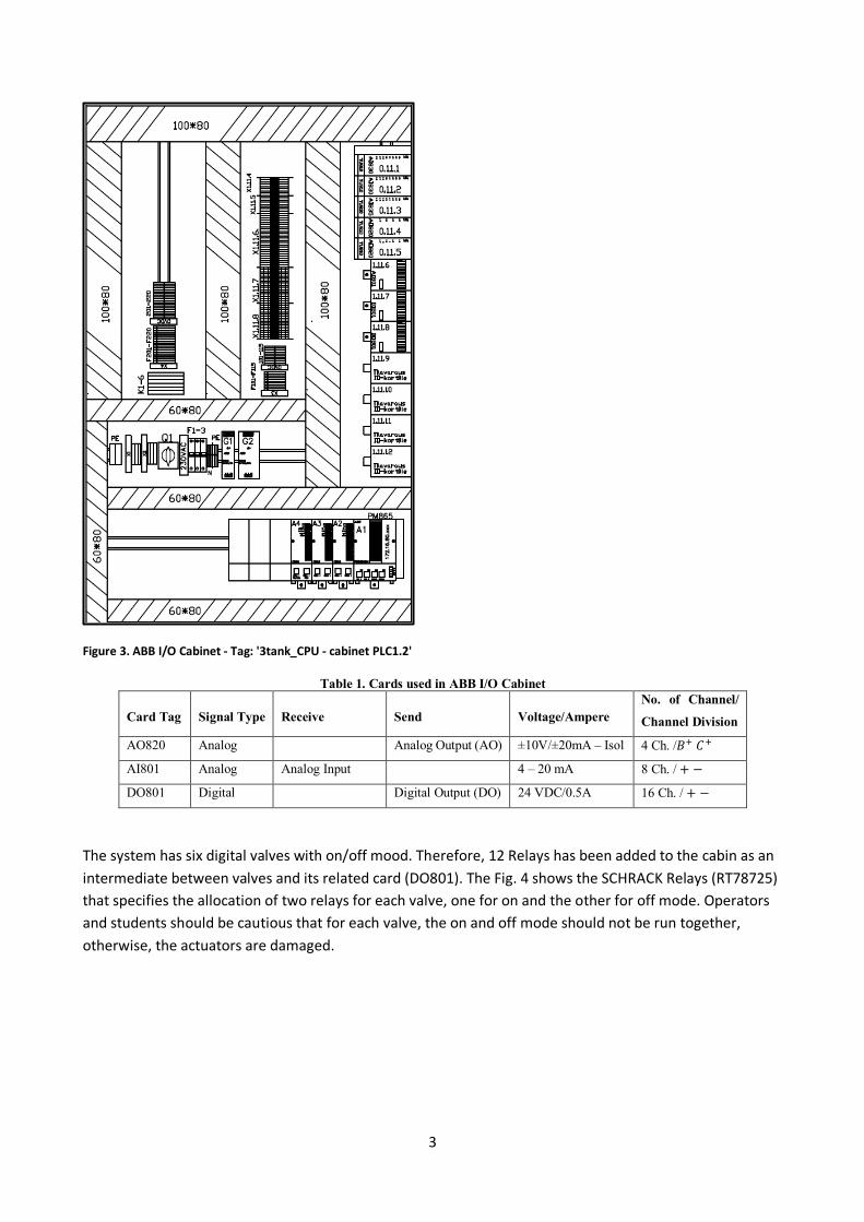
Figure 3. ABB I/O Cabinet - Tag: '3tank_CPU - cabinet PLC1.2'
Table 1. Cards used in ABB I/O Cabinet
Card Tag Signal Type Receive Send Voltage/Ampere No. of Channel/
Channel Division
AO820 Analog Analog Output (AO) ±10V/±20mA – Isol 4 Ch. /𝐵" 𝐶"
AI801 Analog Analog Input 4 – 20 mA 8 Ch. / + −
DO801 Digital Digital Output (DO) 24 VDC/0.5A 16 Ch. / + −
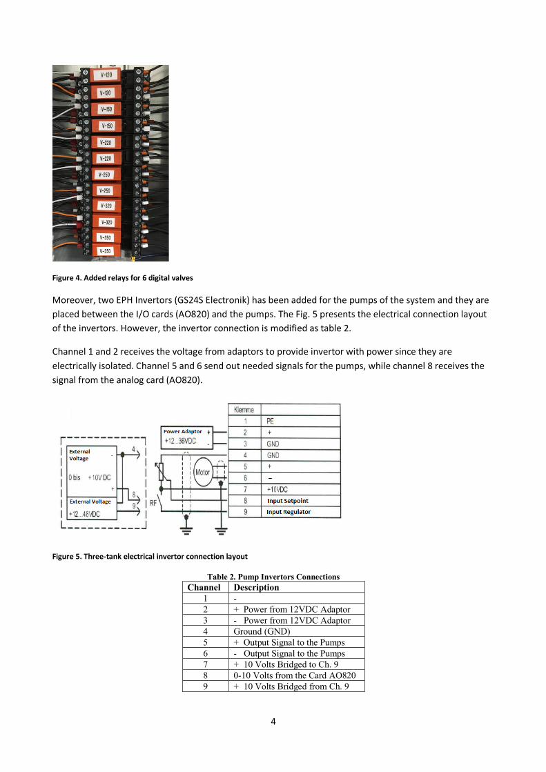
The system has six digital valves with on/off mood. Therefore, 12 Relays has been added to the cabin as an intermediate between valves and its related card (DO801). The Fig. 4 shows the SCHRACK Relays (RT78725) that specifies the allocation of two relays for each valve, one for on and the other for off mode. Operators and students should be cautious that for each valve, the on and off mode should not be run together, otherwise, the actuators are damaged.
4
Figure 4. Added relays for 6 digital valves
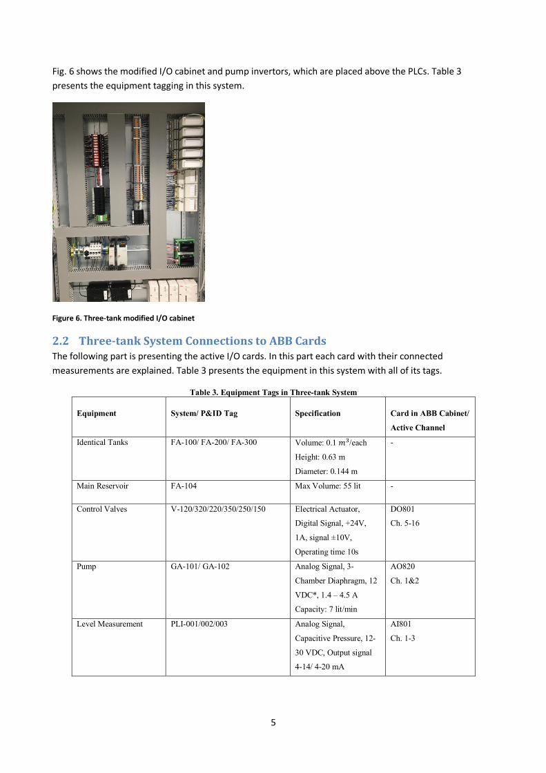
Moreover, two EPH Invertors (GS24S Electronik) has been added for the pumps of the system and they are placed between the I/O cards (AO820) and the pumps. The Fig. 5 presents the electrical connection layout of the invertors. However, the invertor connection is modified as table 2.
Channel 1 and 2 receives the voltage from adaptors to provide invertor with power since they are electrically isolated. Channel 5 and 6 send out needed signals for the pumps, while channel 8 receives the signal from the analog card (AO820).
Figure 5. Three-tank electrical invertor connection layout
Table 2. Pump Invertors Connections Channel Description
1 - 2 + Power from 12VDC Adaptor 3 - Power from 12VDC Adaptor 4 Ground (GND) 5 + Output Signal to the Pumps 6 - Output Signal to the Pumps 7 + 10 Volts Bridged to Ch. 9 8 0-10 Volts from the Card AO820 9 + 10 Volts Bridged from Ch. 9
5
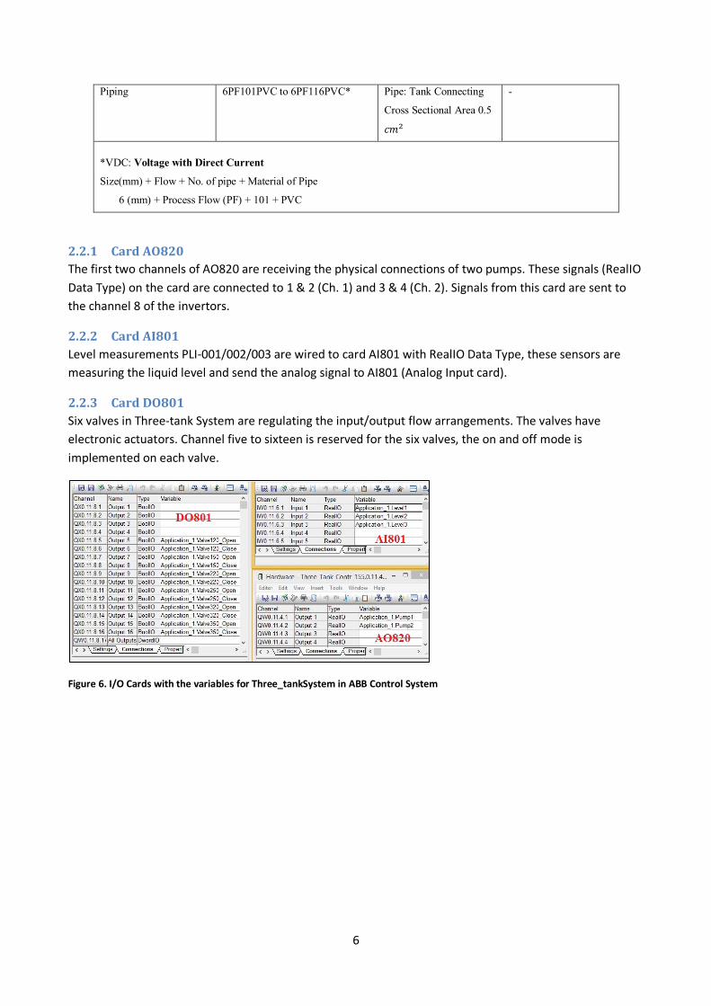
Fig. 6 shows the modified I/O cabinet and pump invertors, which are placed above the PLCs. Table 3 presents the equipment tagging in this system.
Figure 6. Three-tank modified I/O cabinet
2.2 Three-tankSystemConnectionstoABBCardsThe following part is presenting the active I/O cards. In this part each card with their connected measurements are explained. Table 3 presents the equipment in this system with all of its tags.
Table 3. Equipment Tags in Three-tank System
Equipment System/ P&ID Tag Specification Card in ABB Cabinet/
Active Channel
Identical Tanks
FA-100/ FA-200/ FA-300 Volume: 0.1 𝑚'/each
Height: 0.63 m
Diameter: 0.144 m
-
Main Reservoir FA-104 Max Volume: 55 lit -
Control Valves V-120/320/220/350/250/150 Electrical Actuator,
Digital Signal, +24V,
1A, signal ±10V,
Operating time 10s
DO801
Ch. 5-16
Pump GA-101/ GA-102 Analog Signal, 3-
Chamber Diaphragm, 12
VDC*, 1.4 – 4.5 A
Capacity: 7 lit/min
AO820
Ch. 1&2
Level Measurement PLI-001/002/003 Analog Signal,
Capacitive Pressure, 12-
30 VDC, Output signal
4-14/ 4-20 mA
AI801
Ch. 1-3
6
Piping 6PF101PVC to 6PF116PVC* Pipe: Tank Connecting
Cross Sectional Area 0.5
𝑐𝑚)
-
*VDC: Voltage with Direct Current
Size(mm) + Flow + No. of pipe + Material of Pipe
6 (mm) + Process Flow (PF) + 101 + PVC
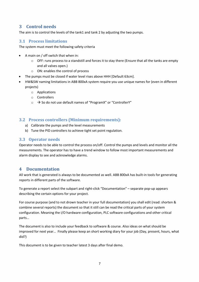
2.2.1 CardAO820The first two channels of AO820 are receiving the physical connections of two pumps. These signals (RealIO Data Type) on the card are connected to 1 & 2 (Ch. 1) and 3 & 4 (Ch. 2). Signals from this card are sent to the channel 8 of the invertors.
2.2.2 CardAI801Level measurements PLI-001/002/003 are wired to card AI801 with RealIO Data Type, these sensors are measuring the liquid level and send the analog signal to AI801 (Analog Input card).
2.2.3 CardDO801Six valves in Three-tank System are regulating the input/output flow arrangements. The valves have electronic actuators. Channel five to sixteen is reserved for the six valves, the on and off mode is implemented on each valve.
Figure 6. I/O Cards with the variables for Three_tankSystem in ABB Control System
7
3 ControlneedsThe aim is to control the levels of the tank1 and tank 2 by adjusting the two pumps.
3.1 ProcesslimitationsThe system must meet the following safety criteria
• A main on / off switch that when in: o OFF: runs process to a standstill and forces it to stay there (Ensure that all the tanks are empty
and all valves open.) o ON: enables the control of process
• The pumps must be closed if water level rises above HHH [Default 63cm]. • HW&SW naming limitations in ABB 800xA system require you use unique names for (even in different
projects) o Applications o Controllers o à So do not use default names of “ProgramX” or “ControllerY”
3.2 Processcontrollers(Minimumrequirements):a) Calibrate the pumps and the level measurements b) Tune the PID controllers to achieve tight set point regulation.
3.3 OperatorneedsOperator needs to be able to control the process on/off. Control the pumps and levels and monitor all the measurements. The operator has to have a trend window to follow most important measurements and alarm display to see and acknowledge alarms.
4 DocumentationAll work that is generated is always to be documented as well. ABB 800xA has built-in tools for generating reports in different parts of the software.
To generate a report select the subpart and right-click “Documentation” – separate pop-up appears describing the certain options for your project.
For course purpose (and to not drown teacher in your full documentation) you shall edit (read: shorten & combine several reports) the document so that it still can be read the critical parts of your system configuration. Meaning the I/O hardware configuration, PLC software configurations and other critical parts…
The document is also to include your feedback to software & course. Also ideas on what should be improved for next year… Finally please keep an short working diary for your job (Day, present, hours, what did?)
This document is to be given to teacher latest 3 days after final demo.

8
5 GradingRoughly the following rules shall apply spring 2019
35 % the PLC basic configuration - HW setup 10% - SW setup 15% - safety criteria operation (look 4.1 process limitations) 10% 10% mixing tank extra systems. (See below) 20 % DCS part (HMI with alarms, trends…) 10 % Documentation Compulsory: working diary 25 % Design the decouplers by using - (a) Simplified decoupling or - (b) Generalized decoupling.
Related Documents