(19) Europaisches Patentamt European Patent Office Office europeen des brevets (12) peen des brevets EP 0 599 648 B1 EUROPEAN PATENT SPECIFICATION (45) Date of publication and mention of the grant of the patent: 24.03.1999 Bulletin 1999/12 (21) Application number: 93309427.8 (22) Date of filing: 25.11.1993 (51) Intel e G01R 29/16 (54) Three-phase power analyzer Dreiphasen-Leistungsanalysator Analyseur de puissance triphase DO 00 ^- CO O) O) lO o a. LU (84) Designated Contracting States: DE FR GB (30) Priority: 25.11.1992 US 981573 (43) Date of publication of application: 01.06.1994 Bulletin 1994/22 (73) Proprietor: ALLEN-BRADLEY COMPANY, INC. Milwaukee Wisconsin 53204 (US) (72) Inventor: Lombardi, Steven Waukesha, Wl 53186 (US) (74) Representative: Robson, Aidan John Reddie & Grose 16 Theobalds Road London WC1X8PL (GB) (56) References cited: EP-A- 0 153 614 US-A- 3 626 281 Note: Within nine months from the publication of the mention of the grant of the European patent, any person may give notice to the European Patent Office of opposition to the European patent granted. Notice of opposition shall be filed in a written reasoned statement. It shall not be deemed to have been filed until the opposition fee has been paid. (Art. 99(1) European Patent Convention). Printed byJouve, 75001 PARIS(FR)

Welcome message from author
This document is posted to help you gain knowledge. Please leave a comment to let me know what you think about it! Share it to your friends and learn new things together.
Transcript
(19)
Europaisches Patentamt
European Patent Office
Office europeen des brevets
(12)
peen des brevets E P 0 5 9 9 6 4 8 B 1
EUROPEAN PATENT S P E C I F I C A T I O N
(45) Date of publication and mention of the grant of the patent: 24.03.1999 Bulletin 1999/12
(21) Application number: 93309427.8
(22) Date of filing: 25.11.1993
(51) Intel e G01R 2 9 / 1 6
(54) Three-phase power analyzer
Dreiphasen-Leistungsanalysator
Analyseur de puissance triphase
DO 00 ^ - CO O) O) lO o a . LU
(84) Designated Contracting States: DE FR GB
(30) Priority: 25.11.1992 US 981573
(43) Date of publication of application: 01.06.1994 Bulletin 1994/22
(73) Proprietor: ALLEN-BRADLEY COMPANY, INC. Milwaukee Wisconsin 53204 (US)
(72) Inventor: Lombardi, Steven Waukesha, Wl 53186 (US)
(74) Representative: Robson, Aidan John Reddie & Grose 16 Theobalds Road London WC1X8PL (GB)
(56) References cited: EP-A- 0 153 614 US-A- 3 626 281
Note: Within nine months from the publication of the mention of the grant of the European patent, any person may give notice to the European Patent Office of opposition to the European patent granted. Notice of opposition shall be filed in a written reasoned statement. It shall not be deemed to have been filed until the opposition fee has been paid. (Art. 99(1) European Patent Convention).
Printed by Jouve, 75001 PARIS (FR)
EP 0 599 648 B1
Description
Field of the Invention
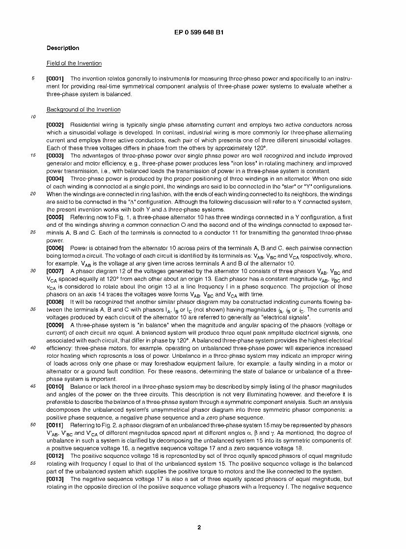
5 [0001] The invention relates generally to instruments for measuring three-phase power and specifically to an instru- ment for providing real-time symmetrical component analysis of three-phase power systems to evaluate whether a three-phase system is balanced.
Background of the Invention 10
[0002] Residential wiring is typically single phase alternating current and employs two active conductors across which a sinusoidal voltage is developed. In contrast, industrial wiring is more commonly for three-phase alternating current and employs three active conductors, each pair of which presents one of three different sinusoidal voltages. Each of these three voltages differs in phase from the others by approximately 120°.
75 [0003] The advantages of three-phase power over single phase power are well recognized and include improved generator and motor efficiency, e.g., three-phase power produces less "iron loss" in rotating machinery, and improved power transmission, i.e., with balanced loads the transmission of power in a three-phase system is constant. [0004] Three-phase power is produced by the proper positioning of three windings in an alternator. When one side of each winding is connected at a single point, the windings are said to be connected in the "star" or "Y" configurations.
20 When the windings are connected in ring fashion, with the ends of each winding connected to its neighbors, the windings are said to be connected in the "A" configuration. Although the following discussion will refer to a Y connected system, the present invention works with both Y and A three-phase systems. [0005] Referring now to Fig. 1 , a three-phase alternator 1 0 has three windings connected in a Y configuration, a first end of the windings sharing a common connection O and the second end of the windings connected to exposed ter-
25 minals A, B and C. Each of the terminals is connected to a conductor 11 for transmitting the generated three-phase power. [0006] Power is obtained from the alternator 10 across pairs of the terminals A, B and C, each pairwise connection being termed a circuit. The voltage of each circuit is identified by its terminals as: VAB, VBC and VCA respectively, where, for example, VAB is the voltage at any given time across terminals A and B of the alternator 10.
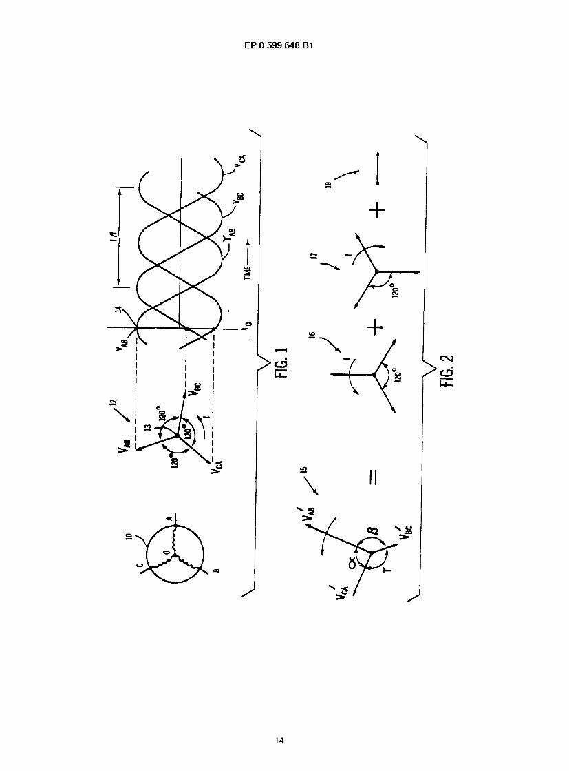
30 [0007] A phasor diagram 12 of the voltages generated by the alternator 10 consists of three phasors VAB, VBC and VCA spaced equally at 120° from each other about an origin 13. Each phasor has a constant magnitude vAB, vBC and vCA is considered to rotate about the origin 13 at a line frequency f in a phase sequence. The projection of these phasors on an axis 1 4 traces the voltages wave forms VAB, VBC and VCA with time. [0008] It will be recognized that another similar phasor diagram may be constructed indicating currents flowing be-
35 tween the terminals A, B and C with phasors lA, lB or lc (not shown) having magnitudes /A, /B or ic. The currents and voltages produced by each circuit of the alternator 10 are referred to generally as "electrical signals". [0009] A three-phase system is "in balance" when the magnitude and angular spacing of the phasors (voltage or current) of each circuit are equal. A balanced system will produce three equal peak amplitude electrical signals, one associated with each circuit, that differ in phase by 120°. A balanced three-phase system provides the highest electrical
40 efficiency: three-phase motors, for example, operating on unbalanced three-phase power will experience increased rotor heating which represents a loss of power. Unbalance in a three-phase system may indicate an improper wiring of loads across only one phase or may foreshadow equipment failure, for example: a faulty winding in a motor or alternator or a ground fault condition. For these reasons, determining the state of balance or unbalance of a three- phase system is important.
45 [0010] Balance or lack thereof in a three-phase system may be described by simply listing of the phasor magnitudes and angles of the power on the three circuits. This description is not very illuminating however, and therefore it is preferable to describe the balance of a three-phase system through a symmetric component analysis. Such an analysis decomposes the unbalanced system's unsymmetrical phasor diagram into three symmetric phasor components: a positive phase sequence, a negative phase sequence and a zero phase sequence.
so [0011] Referring to Fig. 2, a phasor diagram of an unbalanced three-phase system 15 may be represented by phasors V'AB, V'BC and V'CA of different magnitudes spaced apart at different angles a, p and j. As mentioned, the degree of unbalance in such a system is clarified by decomposing the unbalanced system 15 into its symmetric components of: a positive sequence voltage 16, a negative sequence voltage 17 and a zero sequence voltage 18. [0012] The positive sequence voltage 16 is represented by set of three equally spaced phasors of equal magnitude
55 rotating with frequency f equal to that of the unbalanced system 15. The positive sequence voltage is the balanced part of the unbalanced system which supplies the positive torque to motors and the like connected to the system. [0013] The negative sequence voltage 17 is also a set of three equally spaced phasors of equal magnitude, but rotating in the opposite direction of the positive sequence voltage phasors with a frequency f. The negative sequence
2

EP 0 599 648 B1
voltage represents a counter-rotational torque on motors or power loss caused by unbalance in the unbalanced system 15. [0014] The zero sequence voltage 18 is a non-rotating phasor. The zero sequence voltage 18 represents an unbal- anced system 15 such as might be associated with a ground fault in a A system or a neutral current in a Y system. [0015] The vector addition of the phasors of the positive sequence voltage 16, the negative sequence voltage 17 and the zero sequence voltage 18 produce the phasors of the unbalanced system 15. The magnitude of the phasors of the positive, negative and zero sequence voltages for a given unbalanced system 1 5 having phasors V'AB, V'BC and V'CA are calculated as follows:
Pos. Seq. Volt. =
(V'ABr(1Z0°)+(V'Bcr(1Z120o)+(V'CAr(1Z240o)
Neg. Seq. Volt. =
(V'ABr(1Z0°)+(V'Bcr(1Z240o)+(V'CAr(1Z120o) (2)
(V'AB)*(1 Z0°)+(V'BC)*(1 Z0°)+(V'CA)*(1 Z0°) Zero Seq. Volt. = AB B
CA (3)
where, for example, (1Z0°) designates a unit length vector at a phase angle of 0° with respect to some fixed reference generally perpendicular to the projection axis 1 4, and the '*' operator is the scalar or dot product such that:
v1 *v2 = ia, v2 cos 6 (4)
where 6 is the included angle between the vectors or phasors. The results of equations (1) to (3) are scalar functions of time. The magnitude of the phasors for each of the symmetrical components 16, 17, and 18 is the peak value of this scalar function during one cycle. [0016] The magnitude of current vectors for the positive sequence current, the negative sequence current, and the zero sequence current may be, likewise, calculated as follows:
(l')*(1 Z0°)+(l')*(1 Z120°)+(rr)*(1 Z240") Pos. Seq. Cur. = — - - (5)
(rAr(1Z0°)+(l'Br(1Z240o)+(rcr(1Z120°) Neg. Seq. Cur. = — - (6)
(rAr(i^oo)+(rBr(izo°)+(rcr(izo°) Zero Seq. Cur. = — - — (7)
[0017] The similarity of the calculations for the sequence voltages given by equations (1)-(3) and the sequence currents given by equations (5)-(7) will be employed to simplify the following discussion in which "positive sequence", for example, refers to either positive sequence current or positive sequence voltage. The sequences of equations (1 )- (3) and (5)-(7) will be referred to generally as "symmetric sequences". [0018] Despite the usefulness of symmetric component analyses of unbalanced three-phase systems, the determi- nation of the voltages associated with each component phasor requires complex vector mathematics. Such mathe- matical analysis may be readily performed on a digital computer, however, the cost of computer hardware capable of performing these calculation in real-time, or near real-time as is ordinarily desired, is prohibitive for many applications

EP 0 599 648 B1
in which such information is desired. [0019] For this reason, it is known to perform the vector mathematics needed for symmetrical component analyses with "analog" circuitry in which the vector multiplications are approximated by combinations of phase inversions and phase shifting networks of capacitors and inductors and the scalar additions are accomplished with a summing junction.
5 Such analog systems are capable of near real-time calculation of the symmetrical components of a three-phase system but are extremely frequency sensitive and will provide erroneous decompositions if the frequency of the three-phase power shifts significantly from the frequency at which the networks were calibrated. [0020] EP-A-0153614 discloses an instrument for analysing unbalance in three-phase power as reflected in three electrical signals having corresponding phases and amplitudes and together having a phase sequence (page 1 , lines
10 1 -4) comprising a data acquisition means sampling the electrical signals for producing digitized samples of the electrical signals at a plurality of times (page 11 , line 21 ; Figure 11 , reference signs 16R, 16S and 16T) [0021] A method of analysing unbalance in a three-phase system having three electrical signals with corresponding phases and amplitudes and a phase sequence (page 5, line 29 to page 6, line 2), comprising the step of acquiring digitized samples of the amplitudes of the electrical signals at the plurality of times (page 11 , line 22).
15 Summary of the Invention
[0022] Preferred embodiments of the present invention provide a simple and potentially low cost instrument for an- alyzing three-phase power as it may be decomposed into symmetrical sequences to reveal unbalance. The instrument
20 may operate in real time. [0023] Specifically, the instrument employs a data acquisition system receiving the electrical signals for each circuit of the three-phase system. The data acquisition system produces digitized samples of the electrical signals at sample intervals and stores these digitized samples in a computer memory so that the sample number and circuit of the sample are preserved. A memory access device reads samples from the memory for each of the circuits and sums them to
25 create symmetric sequence signals, such as the positive voltage signal. The samples that are summed are offset from each other in sample number so that the phase of the electrical signal of each sample differs from the phase of the electrical signals of the other samples read by substantially 120°. [0024] It is thus one embodiment of the invention avoids the need for complex trigonometric calculations or imprecise analog networks in the computation of symmetric sequences. By storing the signals from each of the three circuits of
30 the three-phase system, the effective vector multiplication may be realized by the calculation of an offset in sample number and the accessing of samples taken at different times. If the sampled data is stored in sequence in computer memory, the sample number offset corresponds simply to an address offset which may be rapidly calculated with current, low cost microprocessors. [0025] An embodiment of the invention also provides negative, positive and zero phase sequence values without
35 the need for additional hardware. An analog circuit for providing each of these symmetric sequences would require additional circuitry for each sequence. In the instrument proposed, the same stored sample values of the three-phase signals may be used to obtain the negative and positive and zero phase sequence of the three-phase system merely by adjusting the address offsets. [0026] The instrument may include a zero-crossing detector for locating a first, second, and third sample in the
40 computer memory for the first, second and third circuits of the three-phase system at which the signals of those circuits first change from negative to positive. These samples may be received by a phase sequence identifier to identify the signal of the second circuit as the second signal of the phase sequence only if the sample number of the second sample is less than the sample number of the third sample and otherwise to identify the signal of the third circuit as the second signal of the phase sequence.
45 [0027] Furthermore the instrument evaluates unbalanced systems, that may be connected to circuits of the three- phase system without regard to the phase sequence of the signals on the particular conductors. The determination of phase sequence for the purpose of calculating of the symmetric sequences may be made automatically. [0028] The instrument may also include a zero-crossing detector which locates a first and second sample in the computer memory for one circuit at which the values of the samples have first changed from negative to positive. A
so ratio engine evaluates the time separating the first and second sample and establishes a corresponding time between samples separated by 1 20° of signal phase. This corresponding time is used by the memory access device to selected the proper samples for calculating the symmetric sequences. [0029] A preferred embodiment thus provides a system for measuring unbalance in a three-phase electrical system that is robust against changes in frequency. Detecting the zero-crossings of the electrical signals allows the sample
55 time to be accurately related to the phase angle of the waveform. After this relationship has been determined, the offset in sample address may be adjusted to accommodate three-phase systems of varying frequency. [0030] The foregoing and other objects and advantages of the invention will appear from the following description. In the description reference is made to the accompanying drawings which form a part hereof and in which there is
4

EP 0 599 648 B1
shown by way of illustration, a preferred embodiment of the invention. Such embodiment does not necessarily represent the full scope of the invention, however, reference must be made therefore to the claims herein for interpreting the scope of the invention.
5 Brief Description of the Drawings
[0031]
Fig. 1 is a schematic representation of the windings of a three-phase alternator and the corresponding voltages 10 produced by that alternator as represented by a phasor diagram and associated graph of voltage amplitude versus
time as described above in the Background of the Invention; Fig. 2 is a pictorial representation of the decomposition of a phasor diagram of an unbalanced three-phase system into a positive sequence, a negative sequence and a zero sequence as also represented by phasor diagrams and as also described above in the Background of the Invention;
is Fig. 3 is an wiring diagram of the connection of the instrument of the present invention, as incorporated into a module of a programmable controller, to two sources of three-phase power; Fig. 4 is a schematic block diagram of the instrument of Fig. 3 incorporating a data acquisition system for sampling the circuits of a three-phase system employing a microcontroller and an associated random access memory re- ceiving those samples;
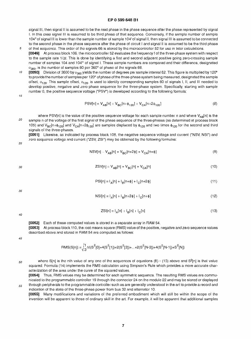
20 Fig. 5 is a flow chart of a program run on the microcontroller of Fig. 4 used to perform symmetrical component analysis in evaluating unbalance in three-phase systems; Fig. 6 is a plot of voltage versus time for a hypothetical three-phase system as monitored by the instrument of Figs. 3 and 4 showing the sample intervals at which data is sampled by the data acquisition of Fig. 4; and Fig. 7 is a representation of a table of samples stored in the memory of Fig. 4 showing points of zero-crossing for
25 each of the three electrical signals of Fig. 6.
Detailed Description of the Preferred Embodiment
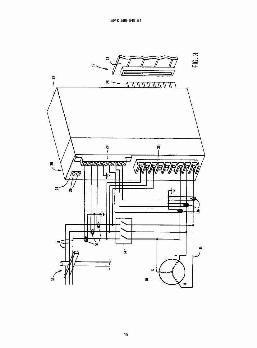
[0032] Referring to Fig. 3, the three-phase monitor 20 of the present invention is incorporated in a module 22 for use 30 in a programmable controller 19 (not shown). Programmable controllers 19, such as are understood to those of ordinary
skill in the art, are specialized computers for use in an industrial environment and are described in U.S. Patent Nos. 3,810,118; 3,942,158; 4,165,534; and 4,442,504, each assigned to the assignee of the present invention. [0033] The monitor 20 communicates with a backplane 23 of the programmable controller 19 through a connector 25 so to obtain operating power and to communicate with other modules that may be included in the programmable
35 controller 19 such as processor module and interconnected input and output (I/O) modules (not shown). [0034] A front panel 24 of the monitor 20 contains status indicating lamps 26, which indicate the proper operation of the circuitry of the monitor 20, and connectors 28 and 30 which allow connection of the monitor 20 to sources of three- phase power as will be described. Connector 30 is a removable connector block such as is taught in U.S. patent 4,151 ,583 hereby incorporated by reference. Connector 28 is a screw type connector intended to prevent inadvertent
40 disconnection of the leads attached to it, as will described further below. [0035] During operation, the monitor 20 is connected to both a three-phase power bus 32, generally being a portion of the power grid from a central supplier, and to a local alternator 10. The speed of the local alternator 10 is typically under the control of the programmable controller 1 9 which transmits control signals from other I/O modules to alternator control circuitry (not shown).
45 [0036] Three conductors of the bus 32 and a corresponding three conductors of the alternator 1 0 are joined through a switch 34 so that alternator 10 may supplement the power from bus 32. Closure of the switch 34 requires that the three-phase systems of the bus 32 and alternator 10 be perfectly synchronized and substantially balanced, otherwise the connection of switch 34 will create potentially damaging high current flow between the alternator 1 0 and the bus 32. [0037] The monitor 20 receives voltage information from each of the conductors of the bus 32 and the alternator 10
so via connections to connector 30. Electrical current information is received by the monitor 20 from the bus 32 and the alternator 10 through current transformers 36 inductively coupled to the conductors 11 of the bus 32 and the alternator 1 0. Leads from these current transformers 36 are connected to connector 28 which, as noted, is constructed to prevent inadvertent disconnection of the secondary of the current transformers 36 from the connector 28 and the monitor 20 while there is current flowing in the primary of the current transformers 36. Such disconnections risk the generation of
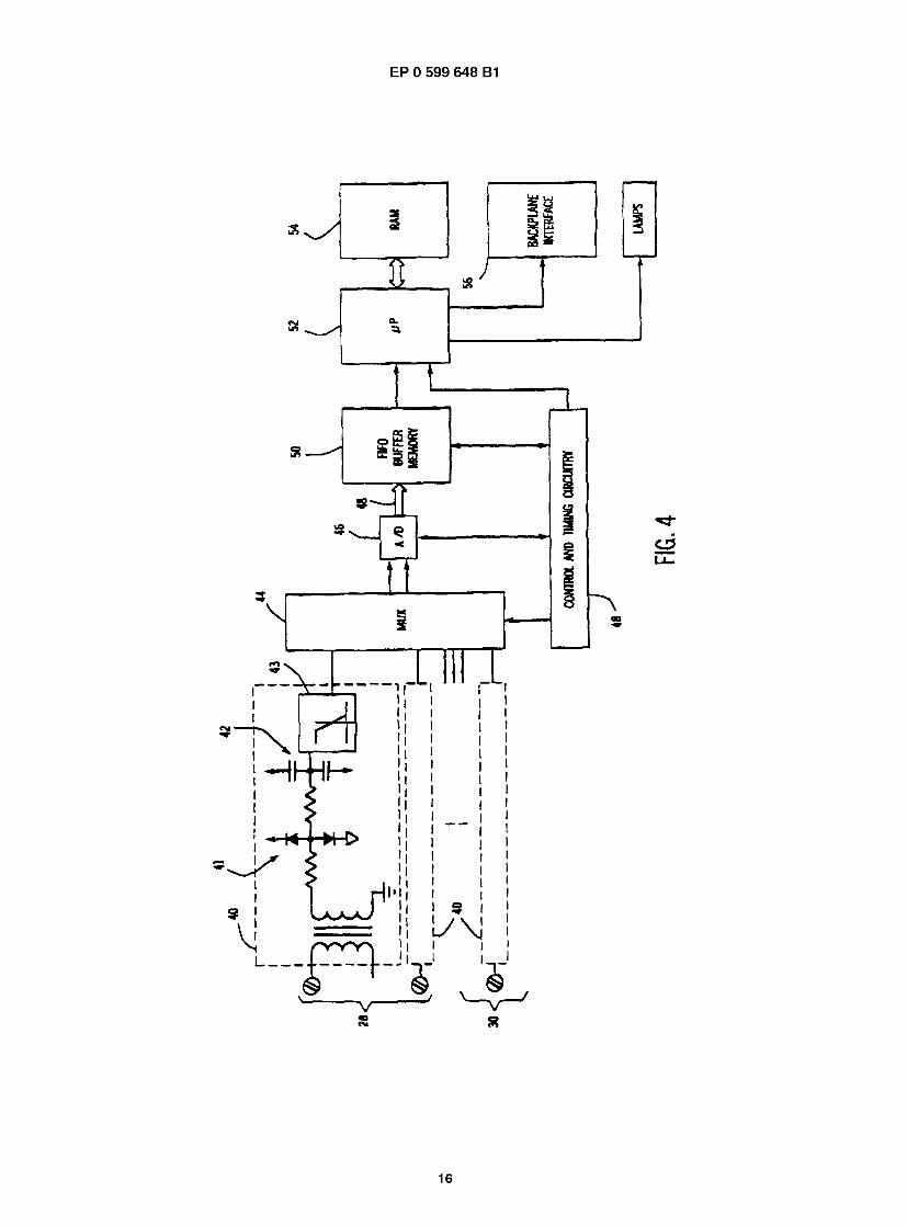
55 "flashover" or arcing at the secondary of the current transformers 36. [0038] Through the connections to connector 28 and 30, the monitor 20 may monitor the voltages of and the current flowing in each of the circuits of the three-phase system of the bus 32 and the alternator 10. [0039] Referring now to Fig. 4, each of the current and voltage inputs, from the bus 32 and alternator 10 to connectors
5

EP 0 599 648 B1
28 and 30, are received by input circuits 40 which provide over-voltage and current protection to the circuitry of the monitor 20 through diode and capacitor networks 41 and 42. Input circuits 40 also include filters 43 to remove high frequency harmonics and noise from the electrical signals of each circuit which might affect the subsequent zero- crossing phase measurements as will be described. In a preferred embodiment, the filters 43 are switched capacitor
5 5th order Butterworth low pass filters with a cutoff frequency of 96 Hz. [0040] The outputs of each input circuit 40 are received by one input of a multiplexor 44 which sequentially connects each of the twelve current and voltage inputs from the three circuits of the bus 32 and alternator 10 to inputs of an analog to digital converter ("A/D convertor") 46 under the control of control and timing circuitry 48. The combined action of the multiplexor 44 and the A/D convertor 46 "samples" the electrical signals of the three-phase circuits to produce
10 digitized sample values which are stored in a first in first out ("FIFO") buffer memory 50. [0041] Each of the multiplexor 44, the A/D convertor 46, and the FIFO memory are coordinated by the control and timing circuitry 48 to store a sufficient number of samples to accurately record a full cycle of the first electrical signal in the phase sequence of each three-phase source ("the first phase") and a full cycle, after the first positive-going zero- crossing of the first phase, of the electrical signals that comprise the second and third phases of the phase sequence.
is [0042] In the preferred embodiment, 64 samples are taken for each cycle of the three-phase systems of each of the twelve circuit connected to the monitor 20. FIFO buffer memory 50 is sized to exceed this requirement and has four kilobytes of memory. [0043] The control and timing circuitry 48 obtains the required complete cycles of the twelve signals representing three circuits of the two sources of the bus 32 and the alternator 10 measured by voltage and current and then stops
20 collection of samples and signals a microcontroller 52 that data has been acquired. Microcontroller 52 reads the FIFO buffer memory 50 into its connected random access memory ("RAM") 54 for determination of the desired symmetric components as will be described. The results of this decomposition may be communicated to the programmable con- troller 19 via backplane 23 (of Fig. 3) via backplane interface 56 described in U.S. Patent 5,065,31 4 hereby incorporated by reference. The data from the symmetric component analysis may be employed by the programmable controller 1 9
25 for control purposes or logged or displayed via a terminal connected to the programmable controller 19. Terminals suitable for this purpose are described in U.S. Patent 4,527,450. The microcontroller 52 also control the illumination of lamps 26. Microcontroller 52 is a general purpose microcontroller such as manufactured by Intel Corporation of Santa Clara, California. [0044] Referring now to Figs. 6 and 7, for both of the three-phase sources 32 or 10 samples 60 are taken, of each
30 of the electrical signals 66 associated with the three-phases, at sample intervals 62 regularly spaced in time by At. The samples 60 are the amplitudes of the electrical signals 66 at the time of the sample interval 62. The samples 60 are arranged in RAM 54 is such that each sample may be identified by a sample number corresponding to the sample interval 62 and being a sequential integer beginning with zero and proceeding to N the last sample interval. Each sample 60 is also be identified to its electrical signal 66 and hence the circuit from which the sample 60 was obtained.
35 This identification may be most simply accomplished by arranging the samples at addresses in RAM 54 that relate to the sample number 61 and electrical signals 66. However, it will be recognized that the sample number and electrical signals may be stored as specific data linked to the data of the samples 60 without regard to the absolute address of the samples 60. For the purpose of discussion it will be assumed that the samples 60 are arranged in a data array in RAM 54 having "columns" by sample number 61 and rows by electrical signal 66.
40 [0045] Generally, the position of the electrical signals 66 within the phase sequence of the three-phase power is not known so the signals are simply identified as I, II and III, respectively rather than VAB, VBC and VCA. Samples obtained for each of the circuits of the three-phase sources 32 and 1 0 in one row, which share a sample number, were acquired during a single sample interval 62 and hence at the same time. [0046] Referring now to Fig. 5, in order to perform the symmetric component analysis, the microcontroller 52 reads
45 the samples from FIFO buffer memory 50 related to either the bus 32 or the alternator 10, and to either the voltage or current of that respective device, into RAM 54 per Fig. 7. This reading of the samples from the FIFO buffer 50 to the memory of the microprocessor 52 is indicated by process block 100. Once the values for each of the samples 60 of the selected three-phase parameter and system are read into RAM 54, at process block 102 the microcontroller 52 reads through the samples 60 for each signal 66 in sequence to identify a sample number 104 at which the sampled
so electrical signal 66 first crosses zero in a positive going direction. This sample number 104 will be referred to as a zero- crossing. One or more such zero-crossing samples are identified for each signal I, II or III. [0047] Because it is assumed in the present system that the circuits of the three-phase system are connected to the terminals of the monitor 20 arbitrarily with respect to their phase sequence, signals I, II and III may not be the first second and third phases of the three-phase system. The proper ordering of the signals I, II and III is therefore determined
55 at process block 105 by locating the first zero-crossing sample 104 of circuit I and first zero-crossing samples 104' and 104" in circuits II and III after that sample 104 of circuit I. [0048] The sample numbers of samples 104' and 104" of signals II and III are compared to the sample number of sample 104 and if the sample number of sample 104" of signal II is less than the sample number of sample 104" of
6
EP 0 599 648 B1
signal III, then signal II is assumed to be the next phase in the phase sequence after the phase represented by signal I. In this case signal III is assumed to be third phase of that sequence. Conversely, if the sample number of sample 104" of signal III is lowerthan the sample number of sample 104' of signal II, then signal III is assumed to be connected to the second phase in the phase sequence after the phase of circuit I and signal II is assumed to be the third phase
5 of that sequence. This order of the signals 66 is stored by the microcontroller 52 for use in later calculations. [0049] At process block 1 06, the microcontroller 52 evaluates the frequency f of the three-phase system with respect to the sample rate 1/At. This is done by identifying a first and second adjacent positive going zero-crossing sample number of samples 104 and 104"' of signal I. These sample numbers are compared and their difference, designated c|>360, is the number of samples 60 per 360° of phase of the signals 66.
10 [0050] Division of 3600 by §3eo yields the number of degrees per sample interval 62. This figure is multiplied by 1 20° to provide the number of samples per 1 20° of phase of the three-phase system being measured, designated the sample offset, (t>120. This sample offset, c|>120, is used to identify corresponding samples 60 of signals I, II, and III needed to develop positive, negative and zero phase sequence for the three-phase system. Specifically, starting with sample number 0, the positive sequence voltage ("PSV") is developed according to the following formula:
15
PSV[n] = VAB[n] + VBC[n+c»120] + VCA[n+2cf120] (8)
where PSV[n] is the value of the positive sequence voltage for each sample number n and where VAB[n] is the 20 sample n of the voltage of the first signal of the phase sequence of the three-phases (as determined at process block
105) and VBC[n+c|>120] and VCA[n+2c|>120] are samples displaced by c|>120 and two times c|>120 for the second and third signals of the three-phases. [0051] Likewise, as indicated by process block 108, the negative sequence voltage and current ("NSV, NSI") and zero sequence voltage and current ("ZSV, ZSI") may be obtained by the following formulas:
25
NSV[n] = VAB[n] + VBC[n+2<|)] + VCA[n+<|)] (9)
30 ZSV[n] = VAB[n] + VBC[n] + VCA[n] (10)
PSI[n] = lA[n] + lB[n+c»] + lc[n+2cM (11)
35 NSI[n] = lA[n] + lB[n+2<|)] + lc[n+<|)] (12)
40
45
ZSI[n] = lA[n] + lB[n] + lc[n] (13)
[0052] Each of these computed values is stored in a separate array in RAM 54. [0053] At process block 1 1 0, the root means square (RMS) value of the positive, negative and zero sequence values described above and stored in RAM 54 are computed as follows:
RMS(S[n]) = J^At(S2[0]+4(S2[1])+2(S2[2])+...+2(S2[N-2])+4(S2[N-1])+S2[N])
50 where S[n] is the nth value of any one of the sequences of equations (8) - (13) above and S2[n] is that value squared. Formula (14) implements the RMS calculation using Simpson's Rule which provides a more accurate char- acterization of the area under the curve of the squared values. [0054] Thus, RMS values may be determined for each symmetric sequence. The resulting RMS values are commu- nicated to the programmable controller 1 9 through the connector 24 on the module 22 and may be stored or displayed
55 through peripherals to the programmable controller such as are generally understood in the art to provide a record and indication of the state of the three-phase power from bus 32 and alternator 10. [0055] Many modifications and variations of the preferred embodiment which will still be within the scope of the invention will be apparent to those of ordinary skill in the art. For example, it will be apparent that additional samples
7

EP 0 599 648 B1
may be obtained for improved accuracy. Further any fiducial point in the waveforms may be used, not just a positive going zero-crossing. Also, it will be understood that at a given sampling rate that interpolation between samples may be used to improve the accuracy of the measurement. In order to apprise the public of the various embodiments that may fall within the scope of the invention, the following claims are made.
5
Claims
1. An instrument for analyzing unbalance in three-phase power as reflected in three electrical signals having corre- 10 sponding phases and amplitudes and together having a phase sequence, comprising:
a data acquisition means (44-50) sampling the electrical signals for producing digitized samples of the electrical signals at a plurality of times; an electronic memory (54) communicating with the data acquisition system for storing the digitized samples
is according to a sample number related to the time of the sample and according to the electrical signal of the sample; memory access means (52) for reading digitized samples in the electronic memory at different sample numbers so that the phase of the electrical signal of each sample differs from the phase of the electrical signals of the other samples read by substantially 120°; and
20 addition means (52) for summing the values of the read samples to produce a symmetrical sequence signal representing the balance of the three-phase system.
2. The instrument of claim 1 wherein the phase of the sample associated with the second electrical signal of the phase sequence lags the phase of the sample associated with the first electrical signal of the phase sequence by
25 1 20° and wherein the addition means produces a sequence signal that is a positive sequence signal.
3. The instrument of claim 2 including in addition an RMS calculation means (52) for receiving the positive sequence signal and producing a positive sequence number that is the RMS value of the positive sequence signal.
30 4. The instrument of claim 1 wherein the phase of the sample associated with the third electrical signal of the phase sequence lags the phase of the sample associated with the first electrical signal of the phase sequence by 120° and wherein the addition means produces a sequence signal that is a negative sequence signal.
5. The instrument of claim 4 including in addition an RMS calculator (52) for receiving the negative sequence signal 35 and producing a negative sequence number that is the RMS value of the negative sequence signal.
6. The instrument of claim 1 wherein the data acquisition system produces digitized samples that are values of current flow in conductors of the three-phase system.
40 7. The instrument of claim 1 wherein the data acquisition system produces digitized samples that are values of voltage across conductors of the three-phase system.
8. The instrument of claim 1 wherein the memory access means includes:
45 a zero-crossing detector for locating a first and second sample number of samples in the electronic memory at which values of the digitized sample for a particular electrical signal first change polarity, the first and second sample numbers associated with samples separated by 360° of phase of the electrical signal; a ratio engine for evaluating the time separating the first and second sample numbers and establishing a corresponding time between samples separated by 120° of phase of the electrical signal;
so wherein the memory access means employs that corresponding time to read digitized samples in the electronic memory for each of the electrical signals so that the phase of the electrical signal of each samples differs from the phase of the electrical signals of the other samples read by substantially 120°.
9. The instrument of claim 1 wherein the memory access means includes: 55
a zero-crossing detector for locating a first, second, and third sample numbers of samples in the electronic memory at which values of a sample for each of the first, second and third of the electrical signals, respectively, first change from negative to positive;
8

EP 0 599 648 B1
a phase sequence identifier for identifying the first electrical signal as the first electrical signal of the phase sequence and the second electrical signal as the second electrical signal of the phase sequence only if the second sample number is before the third sample number.
10. A method of analyzing unbalance in a three-phase system having three electrical signals with corresponding phas- es and amplitudes and a phase sequence comprising the steps of:
acquiring digitized samples of the amplitudes of the electrical signals at a plurality of times; storing the digitized samples at memory addresses according to a sample number related to the time of the sample and according to the electrical signal of the sample; reading the memory to identify a first and second sample number at which values of the digitized sample for a particular electrical signal first change from negative to positive; evaluating the time separating the samples of the first and second sample number to establish a corresponding time between samples separated by 120° of phase of the electrical signal; employing that corresponding time to read digitized samples in the electronic memory for each of the electrical signals so that the phase of the electrical signal of each samples differs from the phase of the electrical signals of the other samples read by substantially 120°; summing the values of the read samples to produce a sequence signal representing the balance of the three- phase system.
11. A method of analyzing unbalance in a three-phase system having three electrical signals with corresponding phas- es and amplitudes and a phase sequence comprising the steps of:
(a) acquiring digitized samples of the amplitudes of the electrical signals at a plurality of times; (b) storing the digitized samples at memory addresses according to a sample number related to the time of the sample and according to the electric signal of the sample in an electronic memory; (c) reading the memory to locate a first, second, and third sample numbers in the electronic memory at which values of a sample for each of the first, second and third of the electrical signals, respectively, change from negative to positive; (d) identifying the first electrical signal as the first electrical signal of the phase sequence and the second electrical signal as the second electrical signal of the phase sequence only if the second sample number is before the third sample number; (e) reading samples from the electronic memory to obtain a first through fifth value of samples for each of the electrical signals, the first value being a value of the first electrical signal of the phase sequence, the second and third values being values of the second electrical signal of the phase sequence lagging the sample of the first value by 1 20° and 240° respectively, the second and third values being values of the third electrical signal of the phase sequence lagging the sample of the first value by 240° and 120° respectively; (f) summing the first, second and fourth values of the read samples to produce a positive sequence signal representing the balance of the three-phase system; (g) summing the first, third and fifth values of the read samples to produce a negative sequence signal repre- senting the balance of the three-phase system.
Patentanspriiche
1. Instrument zum Analysieren von Unsymmetrie in Drehstrom, ausgedruckt durch drei elektrische Signale, die ent- sprechende Phasen und Amplituden und gemeinsam eine Phasenfolge haben, umfassend:
ein Datenerfassungsmittel (44-50) , das die elektrischen Signale abtastet, urn digitalisierte Proben der elek- trischen Signale bei einer Mehrzahl von Zeitpunkten zu erzeugen; einen elektronischen Speicher (54), der mit dem Datenerfassungssystem in Verbindung steht, urn die digita- lisierten Proben gemaB einer Probennummer in bezug auf den Zeitpunkt der Probe und gemaB dem elektri- schen Signal der Probe zu speichern; Speicherzugriffsmittel (52) zum Lesen digitalisierter Proben im elektronischen Speicher an unterschiedlichen Probennummern, so dal3 sich die Phase des elektrischen Signals jeder Probe von der Phase der elektrischen Signale der anderen gelesenen Proben urn im wesentlichen 120°, unterscheidet; und Additionsmittel (52) zum Addieren der Werte der gelesenen Proben, urn ein symmetrisches Folgesignal zu erzeugen, das die Symmetrie des Drehstromsystems reprasentiert.
9
EP 0 599 648 B1
2. Instrument nach Anspruch 1 , bei dem die Phase der Probe in Verbindung mit dem zweiten elektrischen Signal der Phasenfolge hinter der Phase der Probe in Verbindung mit dem ersten elektrischen Signal der Phasenfolge urn 120° nacheilt, und bei dem das Additionsmittel ein Folgesignal erzeugt, das ein positives Folgesignal ist.
5 3. Instrument nach Anspruch 2, das zusatzlich ein Effektivwert-Errechnungsmittel (52) zum Empfangen des positiven Folgesignals und zum Erzeugen einer positiven Folgenummer enthalt, die der Effektivwert des positiven Folgesi- gnals ist.
4. Instrument nach Anspruch 1 , bei dem die Phase der Probe in Verbindung mit dem dritten elektrischen Signal der 10 Phasenfolge hinter der Phase der Probe in Verbindung mit dem ersten elektrischen Signal der Phasenfolge urn
120° nacheilt, und bei dem das Additionsmittel ein Folgesignal erzeugt, das ein negatives Folgesignal ist.
5. Instrument nach Anspruch 4, das zusatzlich einen Effektivwert-Kalkulator (52) zum Empfangen des negativen Folgesignals und zum Erzeugen einer positiven Folgenummer enthalt, die der Effektivwert des negativen Folge-
15 signals ist.
6. Instrument nach Anspruch 1, bei dem das Datenerfassungssystem digitalisierte Proben erzeugt, die StromfluBwerte in Leitern des Drehstromsystems sind.
20 7. Instrument nach Anspruch 1 , bei dem das Datenerfassungssystem digitalisierte Proben erzeugt, die Spannungs- werte iiber Leiter des Drehstromsystems sind.
8. Instrument nach Anspruch 1 , bei dem das Speicherzugriffsmittel folgendes umfaBt:
25 einen Nulldurchgangsdetektor zum Finden einer ersten und einer zweiten Probennummer von Proben im elektronischen Speicher, bei denen Werte der digitalisierten Probe fur ein bestimmtes elektrisches Signal zuerst die Polaritat wechseln, die erste und die zweite Probennummer in Verbindung mit Proben, die urn 360° Phase des elektrischen Signals getrennt sind; ein Verhaltnisprozessor zur Beurteilung der Zeit, die die erste und die zweite Probennummer trennt, und zum
30 Ermitteln einer entsprechenden Zeit zwischen Proben, die urn 120° Phase des elektrischen Signals getrennt sind; wobei das Speicherzugriffsmittel diese entsprechende Zeit benutzt, urn digitalisierte Proben im elektronischen Speicher fur jedes der elektrischen Signale zu lesen, so dal3 sich die Phase des elektrischen Signals aller Proben von der Phase der elektrischen Signale der ubrigen gelesenen Proben urn im wesentlichen 120° un-
35 terscheidet.
9. Instrument nach Anspruch 1 , bei dem das Speicherzugriffsmittel folgendes umfaBt:
einen Nulldurchgangsdetektor zum Finden einer ersten, zweiten und dritten Probennummer von Proben im 40 elektronischen Speicher, bei denen Werte einer Probe fur jedes erste, zweite und dritte elektrische Signal
jeweils zuerst von negativ zu positiv wechseln; einen Phasenfolgenkennerzum Identifizieren des ersten elektrischen Signals als das erste elektrische Signal der Phasenfolge und das zweite elektrische Signal als das zweite elektrische Signal der Phasenfolge nur dann, wenn die zweite Probennummer vor der dritten Probennummer ist.
45 10. Verfahren zum Analysieren von Unsymmetrie in einem Drehstromsystem mit drei elektrischen Signalen mit ent-
sprechenden Phasen und Amplituden und einer Phasenfolge, umfassend die folgenden Schritte:
Erfassen digitalisierter Proben der Amplituden der elektrischen Signale zu einer Mehrzahl von Zeitpunkten; so Speichern der digitalisierten Proben an Speicheradressen gemaB einer Probennummer in bezug auf den Zeit-
punkt der Probe und gemaB dem elektrischen Signal der Probe; Lesen des Speichers zum Identifizieren einer ersten und einer zweiten Probennummer, bei denen Werte der digitalisierten Probe fur ein bestimmtes elektrisches Signal zuerst von negativ auf positiv wechseln; Beurteilen der Zeit, die die Proben der ersten und der zweiten Probennummer trennt, urn eine entsprechende
55 Zeit zwischen Proben zu ermitteln, die urn 120° Phase des elektrischen Signals getrennt sind; Nutzen dieser entsprechenden Zeit, urn digitalisierte Proben im elektronischen Speicher fur jedes der elektri- schen Signale zu lesen, so dal3 sich die Phase des elektrischen Signals der jeweiligen Proben von der Phase der elektrischen Signale der ubrigen gelesenen Proben urn im wesentlichen 120° unterscheidet;
10
EP 0 599 648 B1
Addieren der Werte der gelesenen Proben zum Erzeugen eines Folgesignals, das die Symmetrie des Dreh- stromsystems reprasentiert.
11. Verfahren zum Analysieren von Unsymmetrie in einem Drehstromsystem mit drei elektrischen Signalen mit ent- 5 sprechenden Phasen und Amplituden und einer Phasenfolge, umfassend die folgenden Schritte:
(a) Erfassen digitalisierter Proben der Amplituden der elektrischen Signale zu einer Mehrzahl von Zeitpunkten; (b) Speichern der digitalisierten Proben an Speicheradressen gemaB einer Probennummer in bezug auf den Zeitpunkt der Probe und gemaB dem elektrischen Signal der Probe in einem elektronischen Speicher;
10 (c) Lesen des Speichers zum Finden einer ersten, zweiten und dritten Probennummer im elektronischen Spei- cher, bei denen Werte einer Probe fur jedes erste, zweite und dritte elektrische Signal jeweils von negativ auf positiv wechseln; (d) Identifizieren des ersten elektrischen Signals als das erste elektrische Signal der Phasenfolge und das zweite elektrische Signal als das zweite elektrische Signal der Phasenfolge nur dann, wenn die zweite Pro-
's bennummer vor der dritten Probennummer ist; (e) Lesen von Proben von dem elektronischen Speicher zum Erhalten eines ersten bis funften Wertes von Proben fur jedes der elektrischen Signale, wobei der erste Wert ein Wert des ersten elektrischen signals der Phasenfolge ist, wobei der zweite und der dritte Wert Werte des zweiten elektrischen Signals der Phasenfolge sind, das der Probe des ersten Wertes jeweils urn 120° und 240° nacheilt, wobei der zweite und der dritte
20 Wert Werte des dritten elektrischen Signals der Phasenfolge sind, das der Probe des ersten Wertes jeweils urn 240° und 120° nacheilt; (f) Addieren des ersten, zweiten und vierten Wertes der gelesenen Proben zum Erzeugen eines positiven Folgesignals, das die Symmetrie des Drehstromsystems reprasentiert; (g) Addieren des ersen, dritten und funften Wertes der gelesenen Proben zum Erzeugen eines negativen
25 Folgesignals, das die Symmetrie des Drehstromsystems reprasentiert.
Revendications
30 1. Instrument pour analyser un desequilibre dans une alimentation triphasee tel que reflete dans trois signaux elec- triques ayant des phases et amplitudes correspondantes et ayant ensemble une sequence de phase, comprenant:
un moyen d'acquisition de donnees (44-50) echantillonnant les signaux electriques pour produire des echan- tillons numerises des signaux electriques a une pluralite de temps ;
35 une memoire electronique (54) communiquant avec le systeme d'acquisition de donnees pour memoriser les echantillons numerises selon un numero d'echantillon se rapportant au temps de I'echantillon et selon le signal electrique de I'echantillon ; un moyen d'acces de memoire (52) pour lire des echantillons numerises dans la memoire electronique au niveau de numeros d'echantillons differents de telle sorte que la phase du signal electrique de chaque echan-
40 tillon differe de la phase des signaux electriques des autres echantillons lus par sensiblement 120Q; et un moyen d'addition (52) pour additionner les valeurs des echantillons lus en vue de produire un signal de sequence symetrique representant I'equilibre du systeme triphase.
2. Instrument selon la revendication 1, dans lequel la phase de I'echantillon associe au deuxieme signal electrique 45 de la sequence de phase est en retard par rapport a la phase de I'echantillon associe au premier signal electrique
de la sequence de phase par 120Q et dans lequel le moyen d'addition produit un signal de sequence qui est un signal de sequence positif.
3. Instrument selon la revendication 2, comportant en plus un moyen de calcul de valeur efficace (52) pour recevoir so le signal de sequence positif et produire un numero de sequence positif qui est la valeur efficace du signal de
sequence positif.
4. Instrument selon la revendication 1, dans lequel la phase de I'echantillon associe au troisieme signal electrique de la sequence de phase est en retard par rapport a la phase de I'echantillon associe au premier signal electrique
55 de la sequence de phase par 120Q et dans lequel le moyen d'addition produit un signal de sequence qui est un signal de sequence negatif.
5. Instrument selon la revendication 4, comportant en plus un calculateur de valeur efficace (52) pour recevoir le
11

EP 0 599 648 B1
signal de sequence negatif et produire un numero de sequence negatif qui est la valeur efficace du signal de sequence negatif.
6. Instrument selon la revendication 1, dans lequel le systeme d'acquisition de donnees produit des echantillons 5 numerises qui sont des valeurs du passage de courant dans des conducteurs du systeme triphase.
7. Instrument selon la revendication 1, dans lequel le systeme d'acquisition de donnees produit des echantillons numerises qui sont des valeurs de tension aux bornes de conducteurs du systeme triphase.
10 8. Instrument selon la revendication 1 , dans lequel le moyen d'acces de memoire comporte :
un detecteur de passage au zero pour localiser un premier et un deuxieme numero d'echantillon d'echantillons dans la memoire electronique auxquels les valeurs de I'echantillon numerise d'un signal electrique particulier changent d'abord de polarite, les premier et deuxieme numeros d'echantillon etant associes a des echantillons
is separes par 360Q de phase du signal electrique ; un moteur de rapport pour evaluer le temps separant les premier et deuxieme numeros d'echantillon et etablir un temps correspondant entre les echantillons separes par 120Q de phase du signal electrique ; dans lequel le moyen d'acces de memoire emploie ce temps correspondant pour lire des echantillons nume- rises dans la memoire electronique pour chacun des signaux electriques de telle sorte que la phase du signal
20 electrique de chaque echantillon differe de la phase des signaux electriques des autres echantillons lus par sensiblement 120Q.
9. Instrument selon la revendication 1 , dans lequel le moyen d'acces de memoire comporte :
25 un detecteur de passage au zero pour localiser un premier, un deuxieme et un troisieme numero d'echantillon d'echantillons dans la memoire electronique auxquels les valeurs d'un echantillon pour chacun des premier, deuxieme et troisieme signaux electriques, respectivement, changent d'abord du negatif au positif ; un identificateur de sequence de phase pour identifier le premier signal electrique comme le premier signal electrique de la sequence de phase et le deuxieme signal electrique comme le deuxieme signal electrique de
30 la sequence de phase seulement si le deuxieme numero d'echantillon precede le troisieme numero d'echan- tillon.
10. Procede d'analyse d'un desequilibre dans un systeme triphase ayant trois signaux electriques avec des phases et amplitudes correspondantes et une sequence de phase, comprenant les etapes de :
35 acquisition d'echantillons numerises des amplitudes des signaux electriques a une pluralite de temps ; memorisation des echantillons numerises a des adresses de memoire selon un numero d'echantillon se rap- portant au temps de I'echantillon et selon le signal electrique de I'echantillon ; lecture de la memoire en vue d'identifier un premier et un deuxieme numero d'echantillon auxquels les valeurs
40 de I'echantillon numerise d'un signal electrique particulier changent d'abord du negatif au positif ; evaluation du temps separant les echantillons du premier et du deuxieme numero d'echantillon en vue d'etablir un temps correspondant entre les echantillons separes par 120Q de phase du signal electrique ; emploi de ce temps correspondant en vue de lire des echantillons numerises dans la memoire electronique pour chacun des signaux electriques de telle sorte que la phase du signal electrique de chaque echantillon
45 differe de la phase des signaux electriques des autres echantillons lus par sensiblement 120Q ; addition des valeurs des echantillons lus en vue de produire un signal de sequence representant I'equilibre du systeme triphase.
11. Procede d'analyse d'un desequilibre dans un systeme triphase ayant trois signaux electriques avec des phases so et amplitudes correspondantes et une sequence de phase, comprenant les etapes de :
(a) acquisition d'echantillons numerises des amplitudes des signaux electriques a une pluralite de temps ; (b) memorisation des echantillons numerises a des adresses de memoire selon un numero d'echantillon se rapportant au temps de I'echantillon et selon le signal electrique de I'echantillon dans une memoire
55 electronique ; (c) lecture de la memoire en vue de localiser un premier, un deuxieme et un troisieme numero d'echantillon dans la memoire electronique auxquels les valeurs d'un echantillon pour chacun des premier, deuxieme et troisieme signaux electriques, respectivement, changent du negatif au positif ;
12
EP 0 599 648 B1
(d) identification du premier signal electrique comme le premier signal electrique de la sequence de phase et du deuxieme signal electrique comme le deuxieme signal electrique de la sequence de phase seulement si le deuxieme numero d'echantillon precede le troisieme numero d'echantillon ; (e) lecture d'echantillons dans la memoire electronique en vue d'obtenir une premiere jusqu'a une cinquieme valeur d'echantillon pour chacun des signaux electriques, la premiere valeur etant une valeur du premier signal electrique de la sequence de phase, les deuxieme et troisieme valeurs etant des valeurs du deuxieme signal electrique de la sequence de phase en retard par rapport a I'echantillon de la premiere valeur par 120Q et 240Q respectivement, les quatrieme et cinquieme valeurs etant des valeurs du troisieme signal electrique de la sequence de phase en retard par rapport a I'echantillon de la premiere valeur par 240Q et 120Q respectivement ; (f) addition des premiere, deuxieme et quatrieme valeurs des echantillons lus en vue de produire un signal de sequence positif representant I'equilibre du systeme triphase ; (g) addition des premiere, troisieme et cinquieme valeurs des echantillons lus en vue de produire un signal de sequence negatif representant I'equilibre du systeme triphase.
13
EP 0 599 648 B1
14
EP 0 599 648 B1
5
00

EP 0 599 648 B1
ACQUIRE SAMPLES OF WAVEFORMS FOR CIRCUITS
SEARCH SAMPLES FOR POSITIVE - GOING
ZERO CROSSINGS
LINK CIRCUITS WITH PHASE SEQUENCE
DETERMINE ANGLE
PER SAMPLE
100
,102
SUM SAMPLES BETWEEN CIRCUITS AT SAMPLE OFFSETS
TO GENERATE PHASE SEQUENCES
CALCULATE RMS VALUE OF
PHASE SEQUENCES
105
108
FIG.
17

18
Related Documents