Three-layered damped beam element for forced vibration analysis of symmetric sandwich structures with a viscoelastic core S.G. Won a,b , S.H. Bae a , J.R. Cho a,b , S.R. Bae c , W.B. Jeong a,n a School of Mechanical Engineering, Pusan National University, Kumjung-Ku, Busan 609-735, Republic of Korea b Research and Development Institute of Midas IT, Gyeonggi 463-400, Republic of Korea c Agency for Defense Development, Jinhae 645-016, Republic of Korea article info Article history: Received 1 May 2012 Received in revised form 23 January 2013 Accepted 23 January 2013 Available online 17 February 2013 Keywords: Three-layered damped beam element Symmetric sandwich structures Three-field finite element approximation Forced vibration Convergence DOF-efficiency abstract The numerical implementation of Mead and Markus’s two sets of differential equations of motion governing the damped forced vibration of three-constrained-layer sandwich beam requires C 2 -basis functions or the mixed formulation. To resolve this problem, a damped beam element for three-layered symmetric straight damped sandwich structures is derived according to the virtual work principle, in which both the virtual kinetic and strain energies are expressed in terms of the lateral displacement and the transverse shear strain of a core layer. Because the forced vibration equations of three- constrained-layer damped beam are equipped with three pairs of boundary conditions, the rotation of the mid-surface which is directly derived from the lateral displacement is added for the damped beam element to have three degrees of freedom per node. The shape functions are analytically derived using the compatibility relation between the lateral displacement and the transverse shear strain. The validity of the proposed beam element is verified through the benchmark experiments, and furthermore the DOF-efficiency is justified through the comparison with Nastran 3-D solid element. & 2013 Elsevier B.V. All rights reserved. 1. Introduction The suppression of the structural vibration and noise has been a great challenging subject in various engineering fields during several decades, because a dynamic system or its components with insufficient damping may, but frequently, produce the significantly high vibration which results in the unexpected noise and dynamic instability. According to the very intensive and continuing research efforts, a lot of passive and active devices for reducing the structural vibration have been introduced, and some of them are successfully and widely adopted for a variety of engineering applications. Viscoelastic material among the damp- ing materials employed for such devices is widely used to dissipate the structural vibration energy. The high-damped vis- coelastic film coated on the critical structure members of sub- marine for reducing the underwater noise and the viscoelastic material layer introduced into the cylindrical metallic gun tubes for reducing the structural dynamic deflection become the repre- sentative examples [1,2]. In particular, the viscoelastic layer inserted between the metallic layers exhibits the significantly high damping effect, called the constrained-layer damping [3,4], according to the high shear deformation of the core viscoelastic layer. The structural vibration of a constrained-layer damping sandwich is character- ized by a combination of two distinct deformation modes, the oscillating flexural bending deformation of two metallic faces and the alternating distortional shear deformation of a core viscoe- lastic layer. Then, the transverse shear strain of the viscoelastic member which is induced by the oscillating flexural bending of the metallic members produces the transverse shear stress with the phase lag within the viscoelastic member. As a result, the oscillating vibratory energy of the sandwich structure is dissi- pated via the hysteretic loss of the viscoelastic member. According to our literature survey, the constrained-layer damping has been continuously and intensively studied since the late 1950s, and most of them were motivated by RKU (Ross– Kerwin–Ungar) theory of Ross et al. [5]. They laid down the basic mathematical framework for the viscoelastic constrained-layer sandwich beam and derived the effective, complex and flexural stiffness for the beam section. Since then, based on RKU theory, DiTaranto [4] and Mead and Markus [6] derived the six-order differential equations governing the natural frequencies, the associated composite loss factors and the forced vibration of three-constrained-layer damped beams by introducing the com- plex shear modulus. Theses equations are thought as an extension of Euler beam theory to the viscoelastic laminated beam-like structures so that the problem domain is reduced to the one- dimensional neutral axis of structures [7–9]. Thereafter, the Contents lists available at SciVerse ScienceDirect journal homepage: www.elsevier.com/locate/finel Finite Elements in Analysis and Design 0168-874X/$ - see front matter & 2013 Elsevier B.V. All rights reserved. http://dx.doi.org/10.1016/j.finel.2013.01.004 n Corresponding author. Tel.: þ82 51 510 2337; fax: þ82 51 514 7640. E-mail address: [email protected] (W.B. Jeong). Finite Elements in Analysis and Design 68 (2013) 39–51

Welcome message from author
This document is posted to help you gain knowledge. Please leave a comment to let me know what you think about it! Share it to your friends and learn new things together.
Transcript

Finite Elements in Analysis and Design 68 (2013) 39–51
Contents lists available at SciVerse ScienceDirect
Finite Elements in Analysis and Design
0168-87
http://d
n Corr
E-m
journal homepage: www.elsevier.com/locate/finel
Three-layered damped beam element for forced vibration analysisof symmetric sandwich structures with a viscoelastic core
S.G. Won a,b, S.H. Bae a, J.R. Cho a,b, S.R. Bae c, W.B. Jeong a,n
a School of Mechanical Engineering, Pusan National University, Kumjung-Ku, Busan 609-735, Republic of Koreab Research and Development Institute of Midas IT, Gyeonggi 463-400, Republic of Koreac Agency for Defense Development, Jinhae 645-016, Republic of Korea
a r t i c l e i n f o
Article history:
Received 1 May 2012
Received in revised form
23 January 2013
Accepted 23 January 2013Available online 17 February 2013
Keywords:
Three-layered damped beam element
Symmetric sandwich structures
Three-field finite element approximation
Forced vibration
Convergence
DOF-efficiency
4X/$ - see front matter & 2013 Elsevier B.V.
x.doi.org/10.1016/j.finel.2013.01.004
esponding author. Tel.: þ82 51 510 2337; fax
ail address: [email protected] (W.B. Jeong
a b s t r a c t
The numerical implementation of Mead and Markus’s two sets of differential equations of motion
governing the damped forced vibration of three-constrained-layer sandwich beam requires C2-basis
functions or the mixed formulation. To resolve this problem, a damped beam element for three-layered
symmetric straight damped sandwich structures is derived according to the virtual work principle, in
which both the virtual kinetic and strain energies are expressed in terms of the lateral displacement
and the transverse shear strain of a core layer. Because the forced vibration equations of three-
constrained-layer damped beam are equipped with three pairs of boundary conditions, the rotation
of the mid-surface which is directly derived from the lateral displacement is added for the damped
beam element to have three degrees of freedom per node. The shape functions are analytically derived
using the compatibility relation between the lateral displacement and the transverse shear strain.
The validity of the proposed beam element is verified through the benchmark experiments, and
furthermore the DOF-efficiency is justified through the comparison with Nastran 3-D solid element.
& 2013 Elsevier B.V. All rights reserved.
1. Introduction
The suppression of the structural vibration and noise has beena great challenging subject in various engineering fields duringseveral decades, because a dynamic system or its componentswith insufficient damping may, but frequently, produce thesignificantly high vibration which results in the unexpected noiseand dynamic instability. According to the very intensive andcontinuing research efforts, a lot of passive and active devicesfor reducing the structural vibration have been introduced, andsome of them are successfully and widely adopted for a variety ofengineering applications. Viscoelastic material among the damp-ing materials employed for such devices is widely used todissipate the structural vibration energy. The high-damped vis-coelastic film coated on the critical structure members of sub-marine for reducing the underwater noise and the viscoelasticmaterial layer introduced into the cylindrical metallic gun tubesfor reducing the structural dynamic deflection become the repre-sentative examples [1,2].
In particular, the viscoelastic layer inserted between themetallic layers exhibits the significantly high damping effect,called the constrained-layer damping [3,4], according to the high
All rights reserved.
: þ82 51 514 7640.
).
shear deformation of the core viscoelastic layer. The structuralvibration of a constrained-layer damping sandwich is character-ized by a combination of two distinct deformation modes, theoscillating flexural bending deformation of two metallic faces andthe alternating distortional shear deformation of a core viscoe-lastic layer. Then, the transverse shear strain of the viscoelasticmember which is induced by the oscillating flexural bending ofthe metallic members produces the transverse shear stress withthe phase lag within the viscoelastic member. As a result, theoscillating vibratory energy of the sandwich structure is dissi-pated via the hysteretic loss of the viscoelastic member.
According to our literature survey, the constrained-layerdamping has been continuously and intensively studied sincethe late 1950s, and most of them were motivated by RKU (Ross–Kerwin–Ungar) theory of Ross et al. [5]. They laid down the basicmathematical framework for the viscoelastic constrained-layersandwich beam and derived the effective, complex and flexuralstiffness for the beam section. Since then, based on RKU theory,DiTaranto [4] and Mead and Markus [6] derived the six-orderdifferential equations governing the natural frequencies, theassociated composite loss factors and the forced vibration ofthree-constrained-layer damped beams by introducing the com-plex shear modulus. Theses equations are thought as an extensionof Euler beam theory to the viscoelastic laminated beam-likestructures so that the problem domain is reduced to the one-dimensional neutral axis of structures [7–9]. Thereafter, the
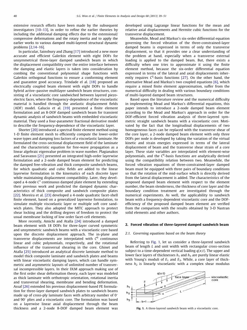
Fig. 1. A three-layered sandwich beam with a viscoelastic core.
S.G. Won et al. / Finite Elements in Analysis and Design 68 (2013) 39–5140
extensive research efforts have been made by the subsequentinvestigators [10–13], in order to refine the earlier theories byincluding the additional damping effects due to the extensional/compressive deformations and the rotary inertia and to apply theearlier works to various damped multi-layered structural dynamicproblems [2,14–16].
In particular, Sainsbury and Zhang [17] introduced a new moreaccurate and efficient Galerkin element with eight DOFs forunsymmetrical three-layer damped sandwich beam in whichthe displacement compatibility over the entire interface betweenthe damping and elastic layers is taken into consideration bycombing the conventional polynomial shape functions withGalerkin orthogonal functions to ensure a conforming elementand guarantee good accuracy. Trindade el al. [18] proposed anelectrically coupled beam element with eight DOFs to handlehybrid active–passive multilayer sandwich beam structures, con-sisting of a viscoelastic core sandwiched between layered piezo-electric faces, where the frequency-dependence of the viscoelasticmaterial is handled through the anelastic displacement fields(ADF) model. Galucio et al. [19] presented a finite elementformulation and an 8-DOF damped sandwich beam for transientdynamic analysis of sandwich beams with embedded viscoelasticmaterial. They used a four-parameter fractional derivative modelto describe the frequency-dependence of the viscoelastic layer.
Shorter [20] introduced a spectral finite element method using1-D finite element mesh to efficiently compute the lower-orderwave types and damping loss factors of a viscoelastic laminate. Heformulated the cross-sectional displacement field of the laminateand the characteristic equation for free-wave propagation as alinear algebraic eigenvalue problem in wave number. Plagianakosand Saravanos [21] presented an integrated high-order layerwiseformulation and a 2-node damped beam element for predictingthe damped free-vibration and thick composite sandwich beams,for which quadratic and cubic fields are added to the linearlayerwise formulation in the kinematics of each discrete layerwhile maintaining displacement compatibility. Later, they devel-oped a 4-node C1 continuous damped plate element by extendingtheir previous work and predicted the damped dynamic char-acteristics of thick composite and sandwich composite plates[22]. Moreira et al. [23] developed a 4-node quadratic facet-shellfinite element, based on a generalized layerwise formulation, tosimulate multiple viscoelastic layer or multiple soft core sand-wich plates. They also adopted the MITC approach to protectshear locking and the drilling degrees of freedom to protect theusual membrane locking of low order facet-cell elements.
More recently, Amichi and Atalla [24] introduced a dampedbeam element with 18 DOFs for three-layer curved symmetricand unsymmetric sandwich beams with a viscoelastic core basedupon the discrete displacement approach. The in-plane andtransverse displacements are interpolated with C0 continuouslinear and cubic polynomials, respectively, and the rotationalinfluence of the transversal shearing in the core. Ghinet andAtalla [25] introduced an analytical discrete laminate method tomodel thick composite laminate and sandwich plates and beamswith linear viscoelastic damping layers, which can handle sym-metric and asymmetric layouts of unlimited number of transver-sal incompressible layers. In their DLM approach making use ofthe first order shear deformation theory, each layer was modeledas thick laminate with orthotropic orientation, rotational inertiaand transversal shearing, membrane and bending deformation.Assaf [26] extended his previous displacement-based FE formula-tion for three-layer damped sandwich plates to sandwich beamsmade up of cross-ply laminate faces with arbitrary number of 01and 901 plies and a viscoelastic core. The formulation was basedon a layerwise linear axial displacement through the beamthickness and a 2-node 8-DOF damped beam element was
developed using Lagrange linear functions for the mean andrelative axial displacements and Hermite cubic functions for thetransverse displacement.
Meanwhile, Mead and Markus’s six-order differential equationgoverning the forced vibration of the three-constrained-layerdamped beams is expressed in terms of only the transversedisplacement, so that it provides one a clear understanding ofthe problem at hand, especially when a transverse externalloading is applied to the damped beam. But, there exists adifficulty when one tries to approximate it using the finiteelement method, because the six-order differential equationexpressed in terms of the lateral and axial displacements inher-ently requires C2-basis functions [27]. On the other hand, thealternative Mead and Markus’s two coupled equations [6], whichrequire a mixed finite element approximation, suffer from thenumerical difficulty in dealing with various boundary conditionsof multi-layered damped beam structures.
Based upon the literature review and the numerical difficultyin implementing Mead and Markus’s differential equations, thispaper intends to introduce a 2-node damped beam elementaccording to the Mead and Markus’s approach in order for theDOF-efficient forced vibration analysis of three-layered sym-metric straight sandwich beams with a viscoelastic core. Moti-vated by the fact that the longitudinal displacements of twohomogeneous faces can be replaced with the transverse shear ofthe core layer, a 2-node damped beam element with only threeDOFs per node is developed by taking the variation of the virtualkinetic and strain energies expressed in terms of the lateraldisplacement of beam and the transverse shear strain of a corelayer. These state variables are interpolated with element-wisepolynomials, and the C0-basis functions are analytically derivedusing the compatibility relation between two. Meanwhile, theforced vibration equations of three-constrained-layer dampedbeam must be equipped with three pairs of boundary conditionsso that the rotation of the mid-surface which is directly derivedfrom the lateral displacement is added. The characteristics of theproposed damped beam element with respect to the elementnumber, the beam slenderness, the thickness of core layer and theboundary condition treatment are investigated through thenumerical experiments. As well, the applicability to sandwichbeam with a frequency-dependent viscoelastic core and the DOF-efficiency of the proposed damped beam element are verifiedfrom the comparison with the results obtained by 3-D Nastransolid elements and other authors.
2. Forced vibration of three-layered damped sandwich beam
2.1. Governing equations based on the beam theory
Referring to Fig. 1, let us consider a three-layered sandwichbeam of length L and unit width with rectangular cross-sectionsubject to a time-dependent vertical loading q(x;t). The upper andlower face layers of thicknesses h1 and h3 are purely linear elasticwith Young’s moduli of E1 and E3. While, a core layer of thick-ness h2 is linearly viscoelastic with a complex shear modulus
S.G. Won et al. / Finite Elements in Analysis and Design 68 (2013) 39–51 41
Gn¼G(1þ iZ) in which Z denotes the loss factor. Throughout this
paper, ( � )n indicate the complex values. The total thickness of thebeam is sufficiently small compared to the beam length, and threelayers are assumed to be completely bonded such that no slippingoccurs at the interfaces.
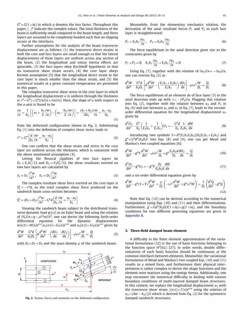
Further assumptions for the analysis of the beam transversedisplacement are as follows: (1) the transverse direct strains inboth the core and face layers are small enough so that the lateraldisplacements of three layers are uniform across any section ofthe beam, (2) the longitudinal and rotary inertia effects areignorable, (3) the face layers obey Kirchhoff hypothesis so thatno transverse shear strain occurs, (4) the core layer obeysKerwin assumption [5] that the longitudinal direct strain in thecore layer is much smaller than the shear strain, and (5) thenumerical results at a given constant temperature are presentedin this paper.
The complex transverse shear stress in the core layer in whichthe longitudinal displacement u is uniform through the thicknessis tn¼Gng¼Gn(qu/qzþqw/qx). Here, the slope of u with respect tothe x-axis is found to be
@u
@z¼
1
h2u1þ
h1
2
@w
@x
� �� u3�
h3
2
@w
@x
� �� �¼ðh1þh3Þ
2h2
@w
@xþ
u1�u3
h2
ð1Þ
from the deformed configuration shown in Fig. 2. SubstitutingEq. (1) into the definition of complex shear stress leads to
tn ¼ Gn d
h2
@w
@xþ
u1�u3
h2
� �ð2Þ
One can confirm that the shear strain and stress in the corelayer are uniform across the thickness, which is consistent withthe above mentioned assumption (4).
Letting the flexural rigidities of two face layers beD1 ¼ E1h3
1=12 and D3 ¼ E3h33=12, the shear resultants exerted on
two face layers are calculated by
S1 ¼D1@3w
@x3, S3 ¼D3
@3w
@x3ð3Þ
The complex resultant shear force exerted on the core layer isSn
2 ¼�tnd, so the total complex shear force produced on thesandwich beam cross-section becomes
Sn
t ¼ D1þD3ð Þ@3w
@x3�Gnd
d
h2
@w
@xþ
u1�u3
h2
� �ð4Þ
Viewing the sandwich beam subject to the distributed trans-verse dynamic load q(x;t) as an Euler beam and using the relationof qSt/qx¼q�rq2w/qt2, one can derive the following forth-orderdifferential equation for the dynamic displacementsw(x;t)¼W(x)eiot,u1(x;t)¼U1(x)eiot and u3(x;t)¼U3(x)eiot given by
d4W
dx4�
Gnd
h2Dtd
d2W
dx2�
dU1
dx�
dU3
dx
� �" #�ro2 W
Dt¼
Q
Dtð5Þ
with Dt¼D1þD3 and the mass density r of the sandwich beam.
Fig. 2. Strains, forces and moments on the deformed configuration.
Meanwhile, from the elementary mechanics relation, thederivation of the axial resultant forces P1 and P2 in each facelayer is straightforward:
P1 ¼ E1h1@u1
@x, P3 ¼ E3h3
@u3
@xð6Þ
The force equilibrium in the axial direction gives rise to theconstraints given by
P1þP3 ¼ 0, E1h1@u1
@xþE3h3
@u3
@x¼ 0 ð7Þ
Using Eq. (7), together with the relation of qu1/qx¼�qu3/qx,one can rewrite Eq. (5) as
d4W
dx4�
Gnd
h2Dtd
d2W
dx2�
E1h1þE3h3
E1h1
� �dU3
dx
" #�ro2 W
Dt¼
Q
Dtð8Þ
The force equilibrium of an element dx of face layer (3) in theaxial direction ends up with t¼�qP3/qx. Plugging this relationinto Eq. (2), together with the relation between u3 and P3 inEq. (6) and one between u3 and u1 in Eq. (7), leads to the second-order differential equation for the longitudinal displacement u3
given by
d2U3
dx2�
Gn
h2
1
E3h3þ
1
E1h1
� �U3 ¼�
Gnd
h2
1
E3h3
dW
dxð9Þ
Introducing two symbols Y¼d2(E1h1E3h3)/Dt(E1h1þE3h3) andgn¼Gnd2/h2DtY into Eqs. (8) and (9), one can get Mead and
Markus’s two coupled equations [6]:
d4W
dx4�gnY
d2W
dx2�ro2 W
Dtþgn E3h3d
Dt
dU3
dx¼
Q
Dtð10Þ
d2U3
dx2�gnU3 ¼�gnY
Dt
E3h3d
dW
dxð11Þ
and a six-order differential equation given by
d6W
dx6�gn 1þYð Þ
d4W
dx4þ
rDt�o2 d2W
dx2þgno2W
!¼
1
Dt
d2Q
dx2�gnQ
!
ð12Þ
Note that Eq. (12) can be derived according to the numericalmanipulation using Eqs. (10) and (11) and their differentiations.Furthermore, g*
¼Gd2/h2DtY(1þ iZ)¼g(1þ iZ), and the boundaryconditions for two different governing equations are given inAppendix B.
3. Three-field damped beam element
A difficulty in the finite element approximation of the varia-tional formulation (12) is the use of basis functions belonging tothe function space H3(0,L) [27]. In order words, double differ-entiations of each basis function should be continuous at thecommon interfaces between elements. Meanwhile, the variationalformulation of Mead and Markus’s two coupled Eqs. (10) and (11)results in a mixed form, and furthermore their physical inter-pretation is rather complex to derive the shape functions and theelement-wise matrices using the energy theory. Additionally, onemay encounter the numerical difficulty in dealing with variousboundary conditions of multi-layered damped beam structures.In this context, we replace the longitudinal displacement u3 withthe transverse shear strain g(x;t)¼G(x)eiot using the relation ofu3¼(dw0 �h2g)/2 which is derived from Eq. (2) for the symmetricdamped sandwich structures.
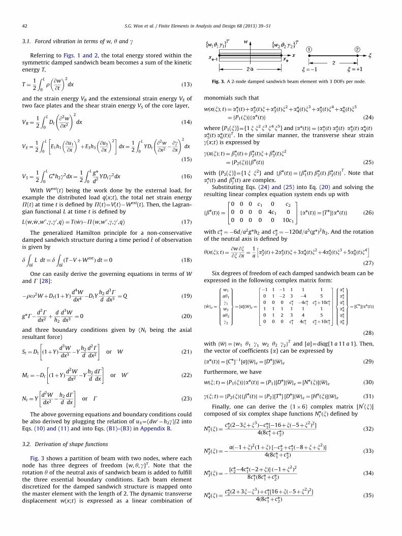
Fig. 3. A 2-node damped sandwich beam element with 3 DOFs per node.
S.G. Won et al. / Finite Elements in Analysis and Design 68 (2013) 39–5142
3.1. Forced vibration in terms of w, y and g
Referring to Figs. 1 and 2, the total energy stored within thesymmetric damped sandwich beam becomes a sum of the kineticenergy T,
T ¼1
2
Z L
0r @w
@t
� �2
dx ð13Þ
and the strain energy VB and the extensional strain energy VE oftwo face plates and the shear strain energy VS of the core layer,
VB ¼1
2
Z L
0Dt
@2w
@x2
!2
dx ð14Þ
VE ¼1
2
Z L
0E1h1
@u1
@x
� �2
þE3h3@u3
@x
� �2" #
dx¼1
2
Z L
0YDt
@2w
@x2�@g@x
!2
dx
ð15Þ
VS ¼1
2
Z L
0Gnh2g2dx¼
1
2
Z L
0
gn
d2YDtg2dx ð16Þ
With Wext(t) being the work done by the external load, forexample the distributed load q(x;t), the total net strain energyP(t) at time t is defined by P(t)¼V(t)�Wext(t). Then, the Lagran-gian functional L at time t is defined by
L w, _w,w00,g,g0,q� �
¼ T _wð Þ�P w,w00,g,g0,q� �
ð17Þ
The generalized Hamilton principle for a non-conservativedamped sandwich structure during a time period ~t of observationis given by
dZ
0~tL dt¼ d
Z0~tðT�VþWext
Þ dt¼ 0 ð18Þ
One can easily derive the governing equations in terms of W
and G [28]:
�ro2WþDt 1þYð Þd4W
dx4�DtY
h2
d
d3Gdx3¼Q ð19Þ
gnG�d2Gdx2þ
d
h2
d3W
dx3¼ 0 ð20Þ
and three boundary conditions given by (Nt being the axialresultant force)
St ¼Dt 1þYð Þd3W
dx3�Y
h2
d
d2Gdx2
" #or W ð21Þ
Mt ¼�Dt 1þYð Þd2W
dx2�Y
h2
d
dGdx
" #or W 0
ð22Þ
Nt ¼ Yd2W
dx2�
h2
d
dGdx
" #or G ð23Þ
The above governing equations and boundary conditions couldbe also derived by plugging the relation of u3¼(dw0 �h2g)/2 intoEqs. (10) and (11) and into Eqs. (B1)–(B3) in Appendix B.
3.2. Derivation of shape functions
Fig. 3 shows a partition of beam with two nodes, where eachnode has three degrees of freedom {w, y, g}T. Note that therotation y of the neutral axis of sandwich beam is added to fulfillthe three essential boundary conditions. Each beam elementdiscretized for the damped sandwich structure is mapped ontothe master element with the length of 2. The dynamic transversedisplacement w(x;t) is expressed as a linear combination of
monomials such that
wðxðxÞ; tÞ ¼ an
1ðtÞþan
2ðtÞxþan
3ðtÞx2þan
4ðtÞx3þan
5ðtÞx4þan
6ðtÞx5
¼ fP1ðxÞgfanðtÞg ð24Þ
where {P1(x)}¼{1x x2x3 x4x5} and fanðtÞg ¼ fan
1ðtÞ an
2ðtÞ an
3ðtÞ an
4ðtÞ
an5ðtÞ an
6ðtÞgT . In the similar manner, the transverse shear strain
g(x;t) is expressed by
gðxðxÞ; tÞ ¼ bn
1ðtÞþbn
2ðtÞxþbn
3ðtÞx2
¼ fP2ðxÞgfbnðtÞg ð25Þ
with {P2(x)}¼{1 x x2} and fbnðtÞg ¼ fbn
1ðtÞ bn
2ðtÞ bn
3ðtÞgT. Note that
an
i ðtÞ and bn
j ðtÞ are complex.Substituting Eqs. (24) and (25) into Eq. (20) and solving the
resulting linear complex equation system ends up with
fbnðtÞg ¼
0 0 0 c1 0 c2
0 0 0 0 4c1 0
0 0 0 0 0 10c1
264
375 fanðtÞg ¼ ½Tn
�fanðtÞg ð26Þ
with cn
1 ¼�6d=a2gnh2 and cn
2 ¼�120d=a5ðgnÞ2h2. And the rotation
of the neutral axis is defined by
y x xð Þ; tð Þ ¼@w
@x@x@x¼
1
aan
2 tð Þþ2an
3 tð Þxþ3an
4 tð Þx2þ4an
5 tð Þx3þ5an
6 tð Þx4h i
ð27Þ
Six degrees of freedom of each damped sandwich beam can beexpressed in the following complex matrix form:
f ~wge ¼
w1
ay1
g1
w2
ay2
g2
8>>>>>>>>><>>>>>>>>>:
9>>>>>>>>>=>>>>>>>>>;¼ ½a�fwge ¼
�1 1 �1 1 1 1
0 1 �2 3 �4 5
0 0 0 cn
1 �4cn
1 cn
2þ10cn
1
1 1 1 1 1 1
0 1 2 3 4 5
0 0 0 cn
1 4cn
1 cn
2þ10cn
1
26666666664
37777777775
an1
an
2
an
3
an
4
an5
an6
8>>>>>>>>><>>>>>>>>>:
9>>>>>>>>>=>>>>>>>>>;¼ ½Cn
�fan tð Þg
ð28Þ
with fwg ¼ fw1 y1 g1 w2 y2 g2gT and [a]¼diag{1 a 11 a 1}. Then,
the vector of coefficients {a} can be expressed by
fanðtÞg ¼ ½Cn��1½a�fwge ¼ ½D
n�fwge ð29Þ
Furthermore, we have
wðx; tÞ ¼ fP1ðxÞgfanðtÞg ¼ fP1g½Dn�fwge ¼ ½N
nðxÞ�fwge ð30Þ
gðx; tÞ ¼ fP2ðxÞgfbnðtÞg ¼ fP2g½T
n� ½Dn�fwge ¼ ½H
nðxÞ�fwge ð31Þ
Finally, one can derive the (1�6) complex matrix [N*(x)]composed of six complex shape functions Nn
i ðxÞ defined by
Nn
1 xð Þ ¼cn
2ð2�3xþx3Þ�cn
1½�16þxð�5þx2Þ2�
4ð8cn
1þcn
2Þð32Þ
Nn
2 xð Þ ¼ �að�1þxÞ2ð1þxÞ ½�cn
2þcn
1ð�8þxþx2Þ�
4ð8cn
1þcn
2Þð33Þ
Nn
3 xð Þ ¼ �½cn
2�4cn
1ð�2þxÞ� ð�1þx2Þ2
8cn
1ð8cn
1þcn
2Þð34Þ
Nn
4 xð Þ ¼cn
2ð2þ3x�x3Þþcn
1½16þxð�5þx2Þ2�
4ð8cn
1þcn
2Þð35Þ
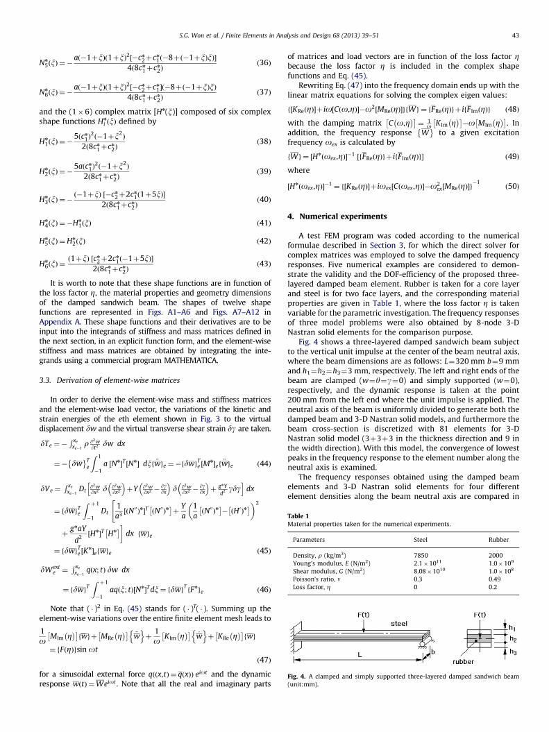
Table 1Material properties taken for the numerical experiments.
Parameters Steel Rubber
Density, r (kg/m3) 7850 2000
Young’s modulus, E (N/m2) 2.1�1011 1.0�109
Shear modulus, G (N/m2) 8.08�1010 1.0�108
Poisson’s ratio, n 0.3 0.49
Loss factor, Z 0 0.2
Fig. 4. A clamped and simply supported three-layered damped sandwich beam
(unit:mm).
S.G. Won et al. / Finite Elements in Analysis and Design 68 (2013) 39–51 43
Nn
5 xð Þ ¼�að�1þxÞð1þxÞ2½�cn
2þcn
1ð�8þð�1þxÞxÞ�4ð8cn
1þcn
2Þð36Þ
Nn
6 xð Þ ¼�að�1þxÞð1þxÞ2½�cn
2þcn
1�ð�8þð�1þxÞxÞ4ð8cn
1þcn
2Þð37Þ
and the (1�6) complex matrix [Hn(x)] composed of six complexshape functions Hn
i ðxÞ defined by
Hn
1 xð Þ ¼�5ðcn
1Þ2ð�1þx2
Þ
2ð8cn
1þcn
2Þð38Þ
Hn
2 xð Þ ¼�5aðcn
1Þ2ð�1þx2
Þ
2ð8cn
1þcn
2Þð39Þ
Hn
3 xð Þ ¼�ð�1þxÞ ½�cn
2þ2cn1ð1þ5xÞ�
2ð8cn
1þcn
2Þð40Þ
Hn
4ðxÞ ¼�Hn
1ðxÞ ð41Þ
Hn
5ðxÞ ¼Hn
2ðxÞ ð42Þ
Hn
6 xð Þ ¼ð1þxÞ ½cn
2þ2cn
1ð�1þ5xÞ�2ð8cn
1þcn
2Þð43Þ
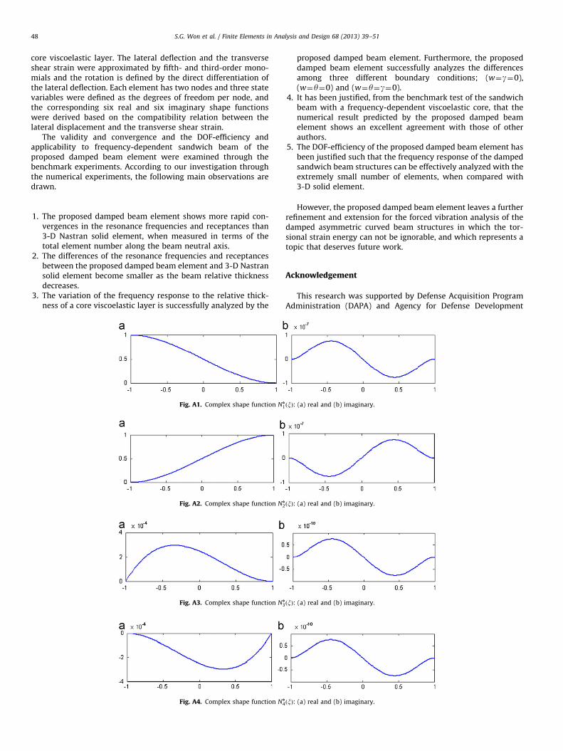
It is worth to note that these shape functions are in function ofthe loss factor Z, the material properties and geometry dimensionsof the damped sandwich beam. The shapes of twelve shapefunctions are represented in Figs. A1–A6 and Figs. A7–A12 inAppendix A. These shape functions and their derivatives are to beinput into the integrands of stiffness and mass matrices defined inthe next section, in an explicit function form, and the element-wisestiffness and mass matrices are obtained by integrating the inte-grands using a commercial program MATHEMATICA.
3.3. Derivation of element-wise matrices
In order to derive the element-wise mass and stiffness matricesand the element-wise load vector, the variations of the kinetic andstrain energies of the eth element shown in Fig. 3 to the virtualdisplacement dw and the virtual transverse shear strain dg are taken.
dTe ¼�R xe
xe�1r @2w
@t2 dw dx
¼� dw� T
e
Z 1
�1a ½Nn
�T ½Nn� dxf €wge ¼�fdwgTe ½M
n�ef€wge ð44Þ
dVe ¼R xe
xe�1Dt
@2w@x2 d @2w
@x2
�þY @2w
@x2 �@g@x
�d @2w
@x2 �@g@x
�þ
gnY
d2 gdgh i
dx
¼ fdwgTe
Z þ1
�1Dt
1
a3½ðN00Þn�T ðN00Þn
� þ
Y
a
1
aðN00Þn�
� ðH0Þn� � �2
"
þgnaY
d2½Hn�T Hn� �
dx fwge
¼ fdwgTe ½Kn�efwge ð45Þ
dWexte ¼
R xe
xe�1qðx; tÞ dw dx
¼ fdwgTZ þ1
�1aqðx; tÞ½Nn
�T dx¼ fdwgT fFnge ð46Þ
Note that ( � )2 in Eq. (45) stands for ( � )T( � ). Summing up theelement-wise variations over the entire finite element mesh leads to
1
o MIm Z� ��
&wf gþ MRe Z� �� €w
n oþ
1
o K Im Z� �� _w
n oþ KRe Z
� �� wf g
¼ fFðZÞgsin ot
ð47Þ
for a sinusoidal external force qððx,tÞ ¼ qðxÞÞ eiot and the dynamicresponse wðtÞ ¼Weiot . Note that all the real and imaginary parts
of matrices and load vectors are in function of the loss factor Zbecause the loss factor Z is included in the complex shapefunctions and Eq. (45).
Rewriting Eq. (47) into the frequency domain ends up with thelinear matrix equations for solving the complex eigen values:
f½KReðZÞ�þ io½Cðo,ZÞ��o2½MReðZÞ�gfWg ¼ fFReðZÞgþ ifFImðZÞg ð48Þ
with the damping matrix C o,Z� ��
¼ 1o K Im Z
� �� �o MIm Z
� �� . In
addition, the frequency response W�
to a given excitationfrequency oex is calculated by
fWg ¼ ½Hnðoex,ZÞ��1 ½fFReðZÞgþ ifFImðZÞg� ð49Þ
where
½Hnðoex,ZÞ��1 ¼ f½KReðZÞ�þ ioex½Cðoex,ZÞ��o2
ex½MReðZÞ�g�1
ð50Þ
4. Numerical experiments
A test FEM program was coded according to the numericalformulae described in Section 3, for which the direct solver forcomplex matrices was employed to solve the damped frequencyresponses. Five numerical examples are considered to demon-strate the validity and the DOF-efficiency of the proposed three-layered damped beam element. Rubber is taken for a core layerand steel is for two face layers, and the corresponding materialproperties are given in Table 1, where the loss factor Z is takenvariable for the parametric investigation. The frequency responsesof three model problems were also obtained by 8-node 3-DNastran solid elements for the comparison purpose.
Fig. 4 shows a three-layered damped sandwich beam subjectto the vertical unit impulse at the center of the beam neutral axis,where the beam dimensions are as follows: L¼320 mm b¼9 mmand h1¼h2¼h3¼3 mm, respectively. The left and right ends of thebeam are clamped (w¼y¼g¼0) and simply supported (w¼0),respectively, and the dynamic response is taken at the point200 mm from the left end where the unit impulse is applied. Theneutral axis of the beam is uniformly divided to generate both thedamped beam and 3-D Nastran solid models, and furthermore thebeam cross-section is discretized with 81 elements for 3-DNastran solid model (3þ3þ3 in the thickness direction and 9 inthe width direction). With this model, the convergence of lowestpeaks in the frequency response to the element number along theneutral axis is examined.
The frequency responses obtained using the damped beamelements and 3-D Nastran solid elements for four differentelement densities along the beam neutral axis are compared in
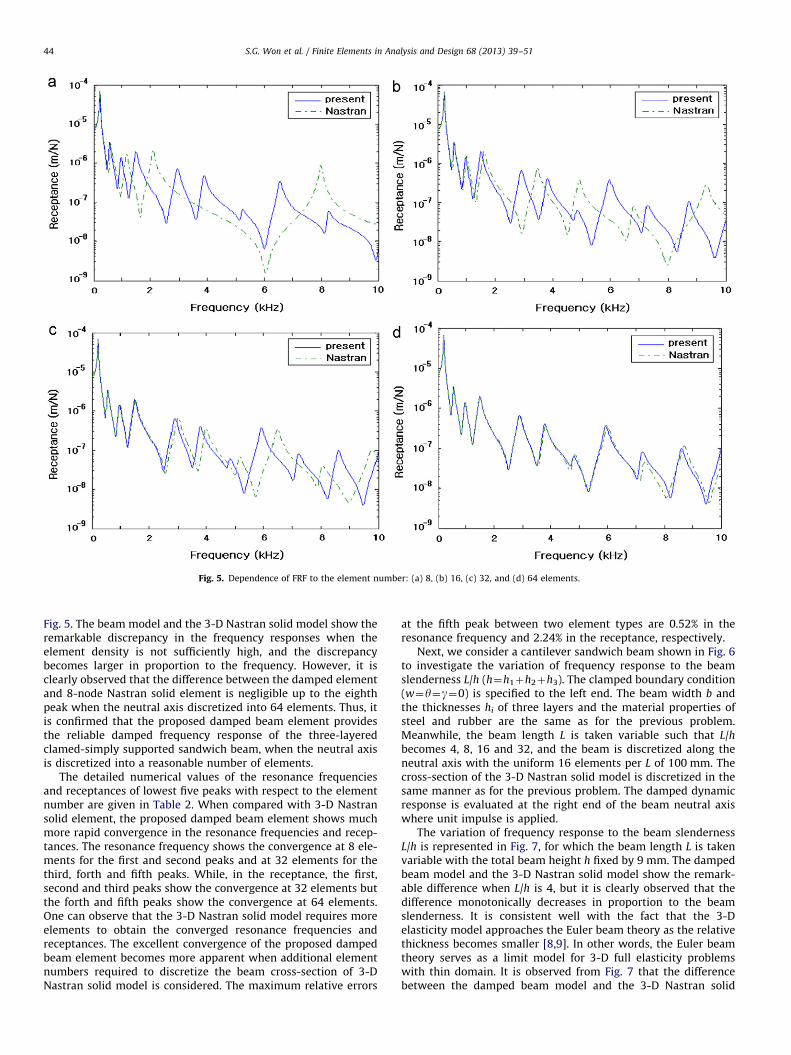
Fig. 5. Dependence of FRF to the element number: (a) 8, (b) 16, (c) 32, and (d) 64 elements.
S.G. Won et al. / Finite Elements in Analysis and Design 68 (2013) 39–5144
Fig. 5. The beam model and the 3-D Nastran solid model show theremarkable discrepancy in the frequency responses when theelement density is not sufficiently high, and the discrepancybecomes larger in proportion to the frequency. However, it isclearly observed that the difference between the damped elementand 8-node Nastran solid element is negligible up to the eighthpeak when the neutral axis discretized into 64 elements. Thus, itis confirmed that the proposed damped beam element providesthe reliable damped frequency response of the three-layeredclamed-simply supported sandwich beam, when the neutral axisis discretized into a reasonable number of elements.
The detailed numerical values of the resonance frequenciesand receptances of lowest five peaks with respect to the elementnumber are given in Table 2. When compared with 3-D Nastransolid element, the proposed damped beam element shows muchmore rapid convergence in the resonance frequencies and recep-tances. The resonance frequency shows the convergence at 8 ele-ments for the first and second peaks and at 32 elements for thethird, forth and fifth peaks. While, in the receptance, the first,second and third peaks show the convergence at 32 elements butthe forth and fifth peaks show the convergence at 64 elements.One can observe that the 3-D Nastran solid model requires moreelements to obtain the converged resonance frequencies andreceptances. The excellent convergence of the proposed dampedbeam element becomes more apparent when additional elementnumbers required to discretize the beam cross-section of 3-DNastran solid model is considered. The maximum relative errors
at the fifth peak between two element types are 0.52% in theresonance frequency and 2.24% in the receptance, respectively.
Next, we consider a cantilever sandwich beam shown in Fig. 6to investigate the variation of frequency response to the beamslenderness L/h (h¼h1þh2þh3). The clamped boundary condition(w¼y¼g¼0) is specified to the left end. The beam width b andthe thicknesses hi of three layers and the material properties ofsteel and rubber are the same as for the previous problem.Meanwhile, the beam length L is taken variable such that L/hbecomes 4, 8, 16 and 32, and the beam is discretized along theneutral axis with the uniform 16 elements per L of 100 mm. Thecross-section of the 3-D Nastran solid model is discretized in thesame manner as for the previous problem. The damped dynamicresponse is evaluated at the right end of the beam neutral axiswhere unit impulse is applied.
The variation of frequency response to the beam slendernessL/h is represented in Fig. 7, for which the beam length L is takenvariable with the total beam height h fixed by 9 mm. The dampedbeam model and the 3-D Nastran solid model show the remark-able difference when L/h is 4, but it is clearly observed that thedifference monotonically decreases in proportion to the beamslenderness. It is consistent well with the fact that the 3-Delasticity model approaches the Euler beam theory as the relativethickness becomes smaller [8,9]. In other words, the Euler beamtheory serves as a limit model for 3-D full elasticity problemswith thin domain. It is observed from Fig. 7 that the differencebetween the damped beam model and the 3-D Nastran solid
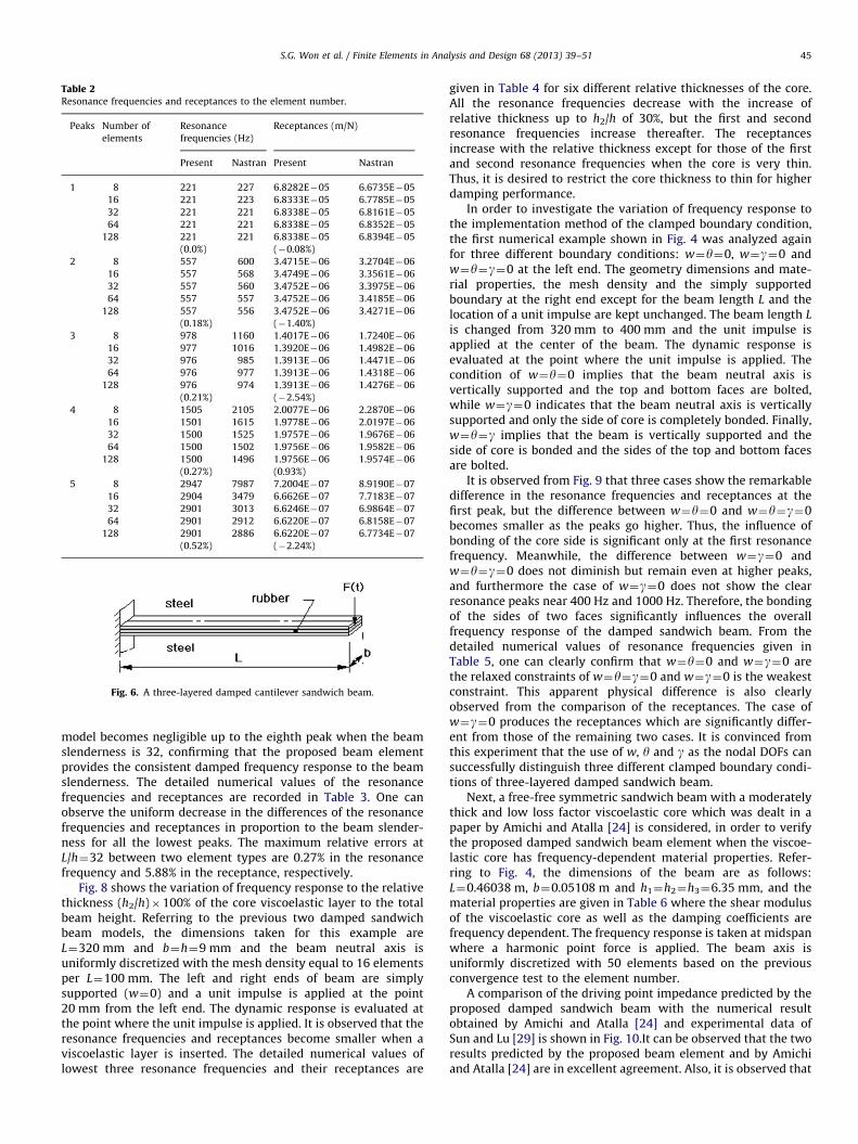
Table 2Resonance frequencies and receptances to the element number.
Peaks Number of
elements
Resonance
frequencies (Hz)
Receptances (m/N)
Present Nastran Present Nastran
1 8 221 227 6.8282E�05 6.6735E�05
16 221 223 6.8333E�05 6.7785E�05
32 221 221 6.8338E�05 6.8161E�05
64 221 221 6.8338E�05 6.8352E�05
128 221
(0.0%)
221 6.8338E�05
(�0.08%)
6.8394E�05
2 8 557 600 3.4715E�06 3.2704E�06
16 557 568 3.4749E�06 3.3561E�06
32 557 560 3.4752E�06 3.3975E�06
64 557 557 3.4752E�06 3.4185E�06
128 557
(0.18%)
556 3.4752E�06
(�1.40%)
3.4271E�06
3 8 978 1160 1.4017E�06 1.7240E�06
16 977 1016 1.3920E�06 1.4982E�06
32 976 985 1.3913E�06 1.4471E�06
64 976 977 1.3913E�06 1.4318E�06
128 976
(0.21%)
974 1.3913E�06
(�2.54%)
1.4276E�06
4 8 1505 2105 2.0077E�06 2.2870E�06
16 1501 1615 1.9778E�06 2.0197E�06
32 1500 1525 1.9757E�06 1.9676E�06
64 1500 1502 1.9756E�06 1.9582E�06
128 1500
(0.27%)
1496 1.9756E�06
(0.93%)
1.9574E�06
5 8 2947 7987 7.2004E�07 8.9190E�07
16 2904 3479 6.6626E�07 7.7183E�07
32 2901 3013 6.6246E�07 6.9864E�07
64 2901 2912 6.6220E�07 6.8158E�07
128 2901
(0.52%)
2886 6.6220E�07
(�2.24%)
6.7734E�07
Fig. 6. A three-layered damped cantilever sandwich beam.
S.G. Won et al. / Finite Elements in Analysis and Design 68 (2013) 39–51 45
model becomes negligible up to the eighth peak when the beamslenderness is 32, confirming that the proposed beam elementprovides the consistent damped frequency response to the beamslenderness. The detailed numerical values of the resonancefrequencies and receptances are recorded in Table 3. One canobserve the uniform decrease in the differences of the resonancefrequencies and receptances in proportion to the beam slender-ness for all the lowest peaks. The maximum relative errors atL/h¼32 between two element types are 0.27% in the resonancefrequency and 5.88% in the receptance, respectively.
Fig. 8 shows the variation of frequency response to the relativethickness (h2/h)�100% of the core viscoelastic layer to the totalbeam height. Referring to the previous two damped sandwichbeam models, the dimensions taken for this example areL¼320 mm and b¼h¼9 mm and the beam neutral axis isuniformly discretized with the mesh density equal to 16 elementsper L¼100 mm. The left and right ends of beam are simplysupported (w¼0) and a unit impulse is applied at the point20 mm from the left end. The dynamic response is evaluated atthe point where the unit impulse is applied. It is observed that theresonance frequencies and receptances become smaller when aviscoelastic layer is inserted. The detailed numerical values oflowest three resonance frequencies and their receptances are
given in Table 4 for six different relative thicknesses of the core.All the resonance frequencies decrease with the increase ofrelative thickness up to h2/h of 30%, but the first and secondresonance frequencies increase thereafter. The receptancesincrease with the relative thickness except for those of the firstand second resonance frequencies when the core is very thin.Thus, it is desired to restrict the core thickness to thin for higherdamping performance.
In order to investigate the variation of frequency response tothe implementation method of the clamped boundary condition,the first numerical example shown in Fig. 4 was analyzed againfor three different boundary conditions: w¼y¼0, w¼g¼0 andw¼y¼g¼0 at the left end. The geometry dimensions and mate-rial properties, the mesh density and the simply supportedboundary at the right end except for the beam length L and thelocation of a unit impulse are kept unchanged. The beam length L
is changed from 320 mm to 400 mm and the unit impulse isapplied at the center of the beam. The dynamic response isevaluated at the point where the unit impulse is applied. Thecondition of w¼y¼0 implies that the beam neutral axis isvertically supported and the top and bottom faces are bolted,while w¼g¼0 indicates that the beam neutral axis is verticallysupported and only the side of core is completely bonded. Finally,w¼y¼g implies that the beam is vertically supported and theside of core is bonded and the sides of the top and bottom facesare bolted.
It is observed from Fig. 9 that three cases show the remarkabledifference in the resonance frequencies and receptances at thefirst peak, but the difference between w¼y¼0 and w¼y¼g¼0becomes smaller as the peaks go higher. Thus, the influence ofbonding of the core side is significant only at the first resonancefrequency. Meanwhile, the difference between w¼g¼0 andw¼y¼g¼0 does not diminish but remain even at higher peaks,and furthermore the case of w¼g¼0 does not show the clearresonance peaks near 400 Hz and 1000 Hz. Therefore, the bondingof the sides of two faces significantly influences the overallfrequency response of the damped sandwich beam. From thedetailed numerical values of resonance frequencies given inTable 5, one can clearly confirm that w¼y¼0 and w¼g¼0 arethe relaxed constraints of w¼y¼g¼0 and w¼g¼0 is the weakestconstraint. This apparent physical difference is also clearlyobserved from the comparison of the receptances. The case ofw¼g¼0 produces the receptances which are significantly differ-ent from those of the remaining two cases. It is convinced fromthis experiment that the use of w, y and g as the nodal DOFs cansuccessfully distinguish three different clamped boundary condi-tions of three-layered damped sandwich beam.
Next, a free-free symmetric sandwich beam with a moderatelythick and low loss factor viscoelastic core which was dealt in apaper by Amichi and Atalla [24] is considered, in order to verifythe proposed damped sandwich beam element when the viscoe-lastic core has frequency-dependent material properties. Refer-ring to Fig. 4, the dimensions of the beam are as follows:L¼0.46038 m, b¼0.05108 m and h1¼h2¼h3¼6.35 mm, and thematerial properties are given in Table 6 where the shear modulusof the viscoelastic core as well as the damping coefficients arefrequency dependent. The frequency response is taken at midspanwhere a harmonic point force is applied. The beam axis isuniformly discretized with 50 elements based on the previousconvergence test to the element number.
A comparison of the driving point impedance predicted by theproposed damped sandwich beam with the numerical resultobtained by Amichi and Atalla [24] and experimental data ofSun and Lu [29] is shown in Fig. 10.It can be observed that the tworesults predicted by the proposed beam element and by Amichiand Atalla [24] are in excellent agreement. Also, it is observed that
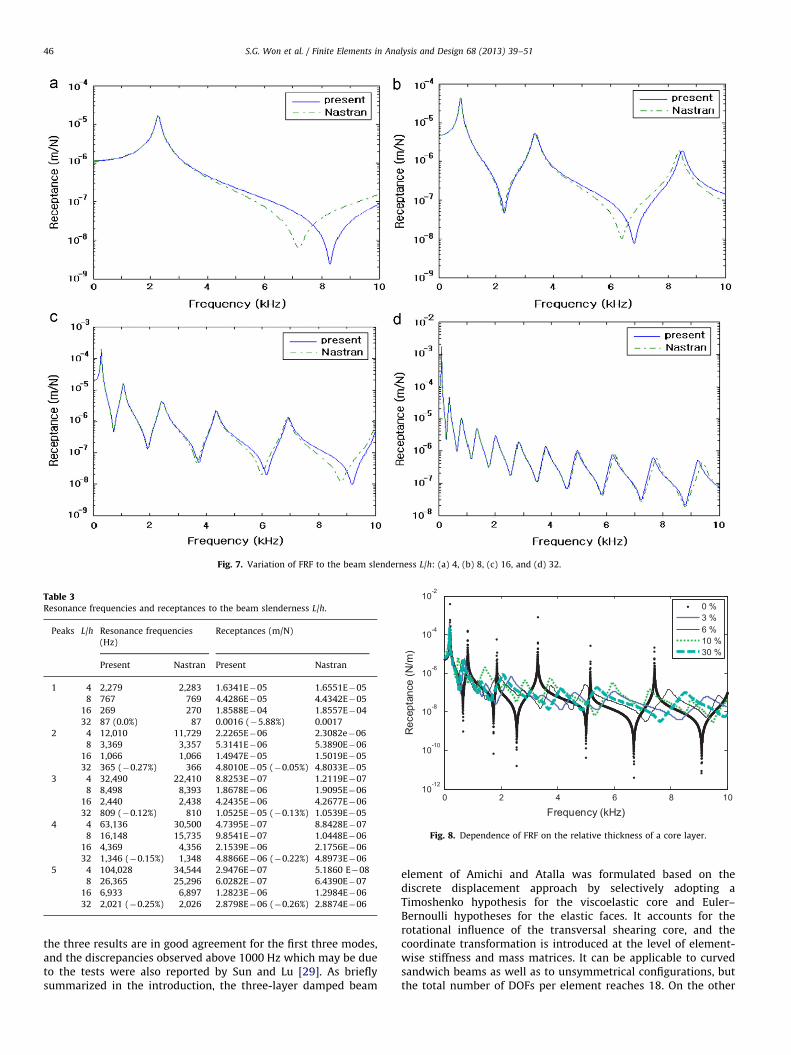
Fig. 7. Variation of FRF to the beam slenderness L/h: (a) 4, (b) 8, (c) 16, and (d) 32.
Table 3Resonance frequencies and receptances to the beam slenderness L/h.
Peaks L/h Resonance frequencies
(Hz)
Receptances (m/N)
Present Nastran Present Nastran
1 4 2,279 2,283 1.6341E�05 1.6551E�05
8 767 769 4.4286E�05 4.4342E�05
16 269 270 1.8588E�04 1.8557E�04
32 87 (0.0%) 87 0.0016 (�5.88%) 0.0017
2 4 12,010 11,729 2.2265E�06 2.3082e�06
8 3,369 3,357 5.3141E�06 5.3890E�06
16 1,066 1,066 1.4947E�05 1.5019E�05
32 365 (�0.27%) 366 4.8010E�05 (�0.05%) 4.8033E�05
3 4 32,490 22,410 8.8253E�07 1.2119E�07
8 8,498 8,393 1.8678E�06 1.9095E�06
16 2,440 2,438 4.2435E�06 4.2677E�06
32 809 (�0.12%) 810 1.0525E�05 (�0.13%) 1.0539E�05
4 4 63,136 30,500 4.7395E�07 8.8428E�07
8 16,148 15,735 9.8541E�07 1.0448E�06
16 4,369 4,356 2.1539E�06 2.1756E�06
32 1,346 (�0.15%) 1,348 4.8866E�06 (�0.22%) 4.8973E�06
5 4 104,028 34,544 2.9476E�07 5.1860 E�08
8 26,365 25,296 6.0282E�07 6.4390E�07
16 6,933 6,897 1.2823E�06 1.2984E�06
32 2,021 (�0.25%) 2,026 2.8798E�06 (�0.26%) 2.8874E�06
0 2 4 6 8 1010
-12
10-10
10-8
10-6
10-4
10-2
Frequency (kHz)
Rec
epta
nce
(N/m
)
0 %3 %6 %10 %30 %
Fig. 8. Dependence of FRF on the relative thickness of a core layer.
S.G. Won et al. / Finite Elements in Analysis and Design 68 (2013) 39–5146
the three results are in good agreement for the first three modes,and the discrepancies observed above 1000 Hz which may be dueto the tests were also reported by Sun and Lu [29]. As brieflysummarized in the introduction, the three-layer damped beam
element of Amichi and Atalla was formulated based on thediscrete displacement approach by selectively adopting aTimoshenko hypothesis for the viscoelastic core and Euler–Bernoulli hypotheses for the elastic faces. It accounts for therotational influence of the transversal shearing core, and thecoordinate transformation is introduced at the level of element-wise stiffness and mass matrices. It can be applicable to curvedsandwich beams as well as to unsymmetrical configurations, butthe total number of DOFs per element reaches 18. On the other
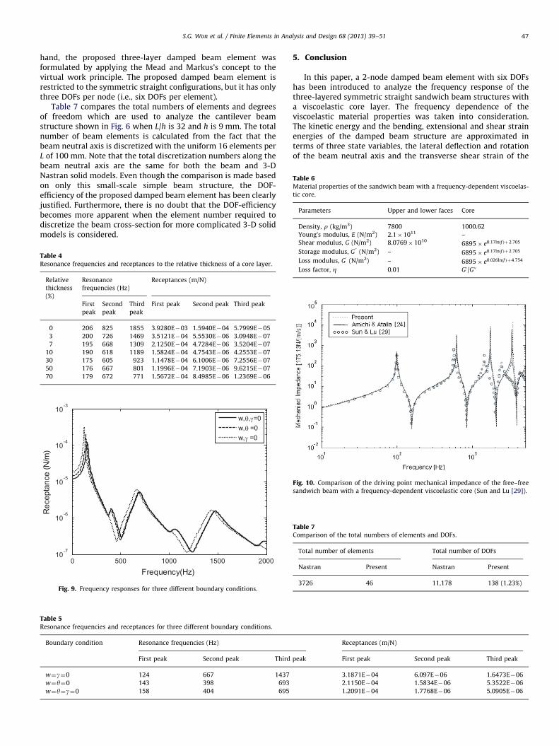
Table 6Material properties of the sandwich beam with a frequency-dependent viscoelas-
tic core.
Parameters Upper and lower faces Core
Density, r (kg/m3) 7800 1000.62
Young’s modulus, E (N/m2) 2.1�1011 –2 10
S.G. Won et al. / Finite Elements in Analysis and Design 68 (2013) 39–51 47
hand, the proposed three-layer damped beam element wasformulated by applying the Mead and Markus’s concept to thevirtual work principle. The proposed damped beam element isrestricted to the symmetric straight configurations, but it has onlythree DOFs per node (i.e., six DOFs per element).
Table 7 compares the total numbers of elements and degreesof freedom which are used to analyze the cantilever beamstructure shown in Fig. 6 when L/h is 32 and h is 9 mm. The totalnumber of beam elements is calculated from the fact that thebeam neutral axis is discretized with the uniform 16 elements perL of 100 mm. Note that the total discretization numbers along thebeam neutral axis are the same for both the beam and 3-DNastran solid models. Even though the comparison is made basedon only this small-scale simple beam structure, the DOF-efficiency of the proposed damped beam element has been clearlyjustified. Furthermore, there is no doubt that the DOF-efficiencybecomes more apparent when the element number required todiscretize the beam cross-section for more complicated 3-D solidmodels is considered.
Table 4Resonance frequencies and receptances to the relative thickness of a core layer.
Relative
thickness
(%)
Resonance
frequencies (Hz)
Receptances (m/N)
First
peak
Second
peak
Third
peak
First peak Second peak Third peak
0 206 825 1855 3.9280E�03 1.5940E�04 5.7999E�05
3 200 726 1469 3.5121E�04 5.5530E�06 3.0948E�07
7 195 668 1309 2.1250E�04 4.7284E�06 3.5204E�07
10 190 618 1189 1.5824E�04 4.7543E�06 4.2553E�07
30 175 605 923 1.1478E�04 6.1006E�06 7.2556E�07
50 176 667 801 1.1996E�04 7.1903E�06 9.6215E�07
70 179 672 771 1.5672E�04 8.4985E�06 1.2369E�06
0 500 1000 1500 200010
-7
10-6
10-5
10-4
10-3
Frequency(Hz)
Rec
epta
nce
(N/m
)
w,θ,γ=0w,θ =0w,γ =0
Fig. 9. Frequency responses for three different boundary conditions.
Table 5Resonance frequencies and receptances for three different boundary conditions.
Boundary condition Resonance frequencies (Hz)
First peak Second peak Third
w¼g¼0 124 667 1437
w¼y¼0 143 398 693
w¼y¼g¼0 158 404 695
5. Conclusion
In this paper, a 2-node damped beam element with six DOFshas been introduced to analyze the frequency response of thethree-layered symmetric straight sandwich beam structures witha viscoelastic core layer. The frequency dependence of theviscoelastic material properties was taken into consideration.The kinetic energy and the bending, extensional and shear strainenergies of the damped beam structure are approximated interms of three state variables, the lateral deflection and rotationof the beam neutral axis and the transverse shear strain of the
Receptances (m/N)
peak First peak Second peak Third peak
3.1871E�04 6.097E�06 1.6473E�06
2.1150E�04 1.5834E�06 5.3522E�06
1.2091E�04 1.7768E�06 5.0905E�06
Shear modulus, G (N/m ) 8.0769�10 6895� e0:17lnðf Þþ2:705
Storage modulus, G00
(N/m2) – 6895� e0:17lnðf Þþ2:705
Loss modulus, G0
(N/m2) – 6895� e0:026lnðf Þþ4:754
Loss factor, Z 0.01 G0/G00
Fig. 10. Comparison of the driving point mechanical impedance of the free–free
sandwich beam with a frequency-dependent viscoelastic core (Sun and Lu [29]).
Table 7Comparison of the total numbers of elements and DOFs.
Total number of elements Total number of DOFs
Nastran Present Nastran Present
3726 46 11,178 138 (1.23%)
S.G. Won et al. / Finite Elements in Analysis and Design 68 (2013) 39–5148
core viscoelastic layer. The lateral deflection and the transverseshear strain were approximated by fifth- and third-order mono-mials and the rotation is defined by the direct differentiation ofthe lateral deflection. Each element has two nodes and three statevariables were defined as the degrees of freedom per node, andthe corresponding six real and six imaginary shape functionswere derived based on the compatibility relation between thelateral displacement and the transverse shear strain.
The validity and convergence and the DOF-efficiency andapplicability to frequency-dependent sandwich beam of theproposed damped beam element were examined through thebenchmark experiments. According to our investigation throughthe numerical experiments, the following main observations aredrawn.
1.
The proposed damped beam element shows more rapid con-vergences in the resonance frequencies and receptances than3-D Nastran solid element, when measured in terms of thetotal element number along the beam neutral axis.2.
The differences of the resonance frequencies and receptancesbetween the proposed damped beam element and 3-D Nastransolid element become smaller as the beam relative thicknessdecreases.3.
The variation of the frequency response to the relative thick-ness of a core viscoelastic layer is successfully analyzed by theFig. A1. Complex shape function Nn
1ðxÞ:
Fig. A2. Complex shape function Nn
2ðxÞ:
Fig. A3. Complex shape function Nn
3ðxÞ:
Fig. A4. Complex shape function Nn
4ðxÞ:
proposed damped beam element. Furthermore, the proposeddamped beam element successfully analyzes the differencesamong three different boundary conditions; (w¼g¼0),(w¼y¼0) and (w¼y¼g¼0).
4.
It has been justified, from the benchmark test of the sandwichbeam with a frequency-dependent viscoelastic core, that thenumerical result predicted by the proposed damped beamelement shows an excellent agreement with those of otherauthors.5.
The DOF-efficiency of the proposed damped beam element hasbeen justified such that the frequency response of the dampedsandwich beam structures can be effectively analyzed with theextremely small number of elements, when compared with3-D solid element.However, the proposed damped beam element leaves a furtherrefinement and extension for the forced vibration analysis of thedamped asymmetric curved beam structures in which the tor-sional strain energy can not be ignorable, and which represents atopic that deserves future work.
Acknowledgement
This research was supported by Defense Acquisition ProgramAdministration (DAPA) and Agency for Defense Development
(a) real and (b) imaginary.
(a) real and (b) imaginary.
(a) real and (b) imaginary.
(a) real and (b) imaginary.

S.G. Won et al. / Finite Elements in Analysis and Design 68 (2013) 39–51 49
(ADD) under Contract No. UD03000AD. This work was supportedby the Human Resources Development of the Korea Institute ofEnergy Technology Evaluation and Planning (KETEP) grant
Fig. A7. Complex shape function Hn
1
Fig. A8. Complex shape function Hn
2
Fig. A9. Complex shape function Hn
3
Fig. A10. Complex shape function H
Fig. A6. Complex shape function Nn
6
Fig. A5. Complex shape function Nn
5
funded by the Korea Ministry of Knowledge Economy (No.20113020020010). The financial support for this work throughWorld Class 300 from Ministry of Knowledge Economy of Korea
ðxÞ: (a) real and (b) imaginary.
ðxÞ: (a) real and (b) imaginary.
ðxÞ: (a) real and (b) imaginary.
n
4ðxÞ: (a) real and (b) imaginary.
ðxÞ: (a) real and (b) imaginary.
ðxÞ: (a) real and (b) imaginary.
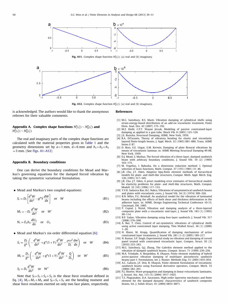
Fig. A11. Complex shape function Hn
5ðxÞ: (a) real and (b) imaginary.
Fig. A12. Complex shape function Hn
6ðxÞ: (a) real and (b) imaginary.
S.G. Won et al. / Finite Elements in Analysis and Design 68 (2013) 39–5150
is acknowledged. The authors would like to thank the anonymousreferees for their valuable comments.
Appendix A. Complex shape functions Nn
1ðxÞ �Nn
6ðxÞ andHn
1ðxÞ �Hn
6ðxÞ
The real and imaginary parts of the complex shape functions arecalculated with the material properties given in Table 1 and thegeometry dimensions set by a¼1 mm, d¼6 mm and h1¼h2¼h3
¼3 mm. (See Figs. A1–A12)
Appendix B. Boundary conditions
One can derive the boundary conditions for Mead and Mar-kus’s governing equations for the damped forced vibration bytaking the symmetric variational formulation.
�
Mead and Markus’s two coupled equations:St ¼Dtd3W
dx3�gnY
dW
dx
" #or W ðB1Þ
Mt ¼�Dtd2W
dx2or W 0
ðB2Þ
Nt ¼ E3h3dU3
dxor U3 ðB3Þ
�
Mead and Markus’s six-order differential equation [6]:St ¼Dt
gn�
d5W
dx5þgn 1þYð Þ
d3W
dx3�ro2
Dt
dw
dx
!or W ðB4Þ
Mt ¼Dt
gn�
d4W
dx4þgn 1þYð Þ
d2W
dx2þ
Q
Dt
!or W 0
ðB5Þ
Sf ¼Dtd3W
dx3or W 00
ðB6Þ
Note that St¼S1þS2þS3 is the shear force resultant defined inEq. (4), Mt¼M1þM3 and Sf¼S1þS3 are the bending moment andshear force resultants exerted on only two face plates, respectively.
References
[1] M.G. Sainsbury, R.S. Masti, Vibration damping of cylindrical shells usingstrain-energy-based distribution of an add-on viscoelastic treatment, FiniteElem. Anal. Des. 43 (2007) 175–192.
[2] M.Z. Kiehl, C.P.T. Wayne Jerzak, Modeling of passive constrained-layerdamping as applied to a gun tube, Shock Vib. 8 (2001) 123–129.
[3] J.E. Ruzicka, Structural Damping, ASME, New York, 1959.[4] R.A. DiTaranto, Theory of vibratory bending for elastic and viscoelastic
layered finite-length beams, J. Appl. Mech. 32 (1965) 881–886, Trans. ASMESeries E 87.
[5] D. Ross, E.E. Ungar, E.M. Kerwin, Damping of plate flexural vibrations bymeans of viscoelastic laminae, in: ASME Meeting Structural Damping 49-88,New York, 1959.
[6] D.J. Mead, S. Markus, The forced vibration of a three-layer, damped sandwichbeam with arbitrary boundary conditions, J. Sound Vib. 10 (2) (1969)163–175.
[7] M. Vogelius, I. Babuska, On a dimension reduction method; I. Optimalselection of basis functions, Math. Comput. 37 (155) (1981) 31–46.
[8] J.R. Cho, J.T. Oden, Adaptive hpq-finite element methods of hierarchicalmodels for plate- and shell-like structures, Comput. Meth. Appl. Mech. Eng.136 (1995) 317–345.
[9] J.R. Cho, J.T. Oden, A priori modeling error estimates of hierarchical modelsfor elasticity problems for plate- and shell-like structures, Math. Comput.Modell. 32 (10) (1996) 117–133.
[10] Y.V.K. Sadasiva Rao, B.C. Nakra, Vibrations of unsymmetrical sandwich beamsand plates with viscoelastic cores, J. Sound Vib. 34 (3) (1974) 309–326.
[11] R.N. Miles, P.G. Reinhall, An analytical model for the vibration of laminatedbeams including the effects of both shear and thickness deformation in theadhesive layer, in: ASME, Design Engineering Technical Conference 10-13,Cincinnati, OH, 1985.
[12] P. Cupial, J. Niziol, Vibration and damping analysis of a three-layeredcomposite plate with a viscoelastic mid-layer, J. Sound Vib. 183 (1) (1995)99–114.
[13] B.P. Yadav, Vibration damping using four-layer sandwich, J. Sound Vib. 317(2008) 576–590.
[14] A. Baz, T. Chen, Control of axi-symmetric vibrations of cylindrical shellsusing active constrained layer damping, Thin Walled Struct. 36 (1) (2000)1–20.
[15] H. Illaire, W. Kropp, Quantification of damping mechanisms of activeconstrained layer treatments, J. Sound Vib. 281 (1–2) (2005) 189–217.
[16] N. Kumar, S.P. Singh, Experimental study on vibration and damping of curvedpanel treated with constrained viscoelastic layer, Compos. Struct. 92 (2)(2010) 233–243.
[17] M.G. Sainsbury, Q.J. Zhang, The Galerkin element method applied to thevibration of damped sandwich beams, Comput. Struct. 71 (1999) 239–256.
[18] M.A. Trindade, A. Benjeddou, R. Ohayon, Finite element modeling of hybridactive-passive vibration damping of multilayer piezoelectric sandwichbeams-part I: Formulation, Int. J. Numer. Methods Eng. 51 (2001) 835–854.
[19] A.C. Galucio, J.F. Deu, R. Ohayon, Finite element formulation of viscoelasticsandwich beams using fractional derivative operators, Comput. Mech. 33(2004) 282–291.
[20] P.J. Shorter, Wave propagation and damping in linear vviscoelastic laminates,J. Acoust. Soc. Am. 115 (5) (2004) 1917–1925.
[21] T.S. Plagianakos, D.A. Saravanos, High-order layerwise mechanics and finiteelement for the damped dynamic characteristics of sandwich compositebeams, Int. J. Solids Struct. 41 (2004) 6853–6871.
S.G. Won et al. / Finite Elements in Analysis and Design 68 (2013) 39–51 51
[22] T.S. Plagianakos, D.A. Saravanos, High-order finite element for the dampedfree-vibration response of thick composite and sandwich composite plate,Int. J. Numer. Methods Eng. 77 (2009) 1593–1626.
[23] R.A.S. Moreira, J. Dias Rodrigues, A.J.M. Ferreira, A generalized layerwise finiteelement for multi-layer damping treatmenst, Comput. Mech. 37 (2006) 426–444.
[24] K. Amichi, N. Atalla, A new 3D finite element for sandwich beams with aviscoelastic core, ASME J. Vib. Acoust. 131 (2009) 021010.
[25] S. Ghinet, N. Atalla, Modeling thick composite laminate and sandwich structureswith linear viscoelastic damping, Comput. Struct. 89 (2011) 1547–1561.
[26] S. Assaf, Finite element vibration analysis of damped composite sandwichbeams, Int. J. Acoust. Vibr. 16 (4) (2011) 163–172.
[27] J.T. Oden, L.F. Demkowicz, Applied Functional Analysis, CRC Press, New York,1996.
[28] D.K. Rao, Frequency and loss factors of sandwich beams under variousboundary conditions, Proc. Inst. Mech. Eng. Part C J. Mech. Eng. Sci. 20 (5)(1978) 271–282.
[29] C.T. Sun, Y.P. Lu, Vibration Damping of Structural Elements, Prentice-Hall,Englewood Cliffs, NJ, 1995.
Related Documents