THREE DIMENSIONAL STRESS STRAIN ANALYSIS OF THE \ LUMBAR SPINE BY FINITE ELEMENT METHOD by VIJAY KUMAR MITTAL, B.S. A THESIS IN CIVIL ENGINEERING Submitted to the Graduate Faculty of Texas Tech University in Partial Fulfillment of the Requirements for the Degree of MASTER OF SCIENCE IN CIVIL ENGINEERING Approved H May, 1974 I

Welcome message from author
This document is posted to help you gain knowledge. Please leave a comment to let me know what you think about it! Share it to your friends and learn new things together.
Transcript

THREE DIMENSIONAL STRESS STRAIN ANALYSIS OF THE \
LUMBAR SPINE BY FINITE ELEMENT METHOD
by
VIJAY KUMAR MITTAL, B.S.
A THESIS
IN
CIVIL ENGINEERING
Submitted to the Graduate Faculty of Texas Tech University in Partial Fulfillment of the Requirements for
the Degree of
MASTER OF SCIENCE
IN
CIVIL ENGINEERING
Approved
H May, 1974 I
SOS-T3
Cop. Z
ACKNOWLEDGMENTS
I am deeply indebted to Dr. C. V. G. Vallabhan for
his guidance and counseling during this investigation and
also for serving as Chairman of the Advisory Committee.
I also wish to express my deep appreciation to Dr. Ernst
W. Kiesling for his guidance and encouragement throughout
my graduate studies at Texas Tech University. I am also
grateful to Dr. M. M. Ayoub and Dr. Jimmy H. Smith for
their helpful criticisms and valuable suggestions.
11
TABLE OF CONTENTS
Page
ACKNOWLEDGMENTS ii
LIST OF TABLES iv
LIST OF FIGURES v
LIST OF SYMBOLS vii
CHAPTER
I. INTRODUCTION 1
Review of Previous Research 2
Finite Element Method 6
Scope of the Research 7
II. LUMBAR SPINE PROBLEMS 8
Dimensions of the Lumbar Spine . . . . 9
Material Properties of Lumbar Spine . . 11
III. THE FINITE ELEMENT METHOD 14
IV. ANALYSIS OF LUMBAR SPINE 28
V. SUMMARY, CONCLUSIONS AND RECOMMENDATIONS FOR FURTHER STUDY 51
Summary 51
Conclusions 52
Recommendations for Further Study . . . 53
REFERENCES 56
• • •
111

LIST OF TABLES
TABLE Page
2.1 X-rays and Anthropological Data on Normal Subjects 12
3.1 [q]* [D] [q] [V] for Tetrahedron Element . . . 25
IV
LIST OF FIGURES
FIG. Page
1.1 Load Deformation Curve 5
2.1 Geometric Measurements 10
3.1 A Tetrahedron Finite Element 17
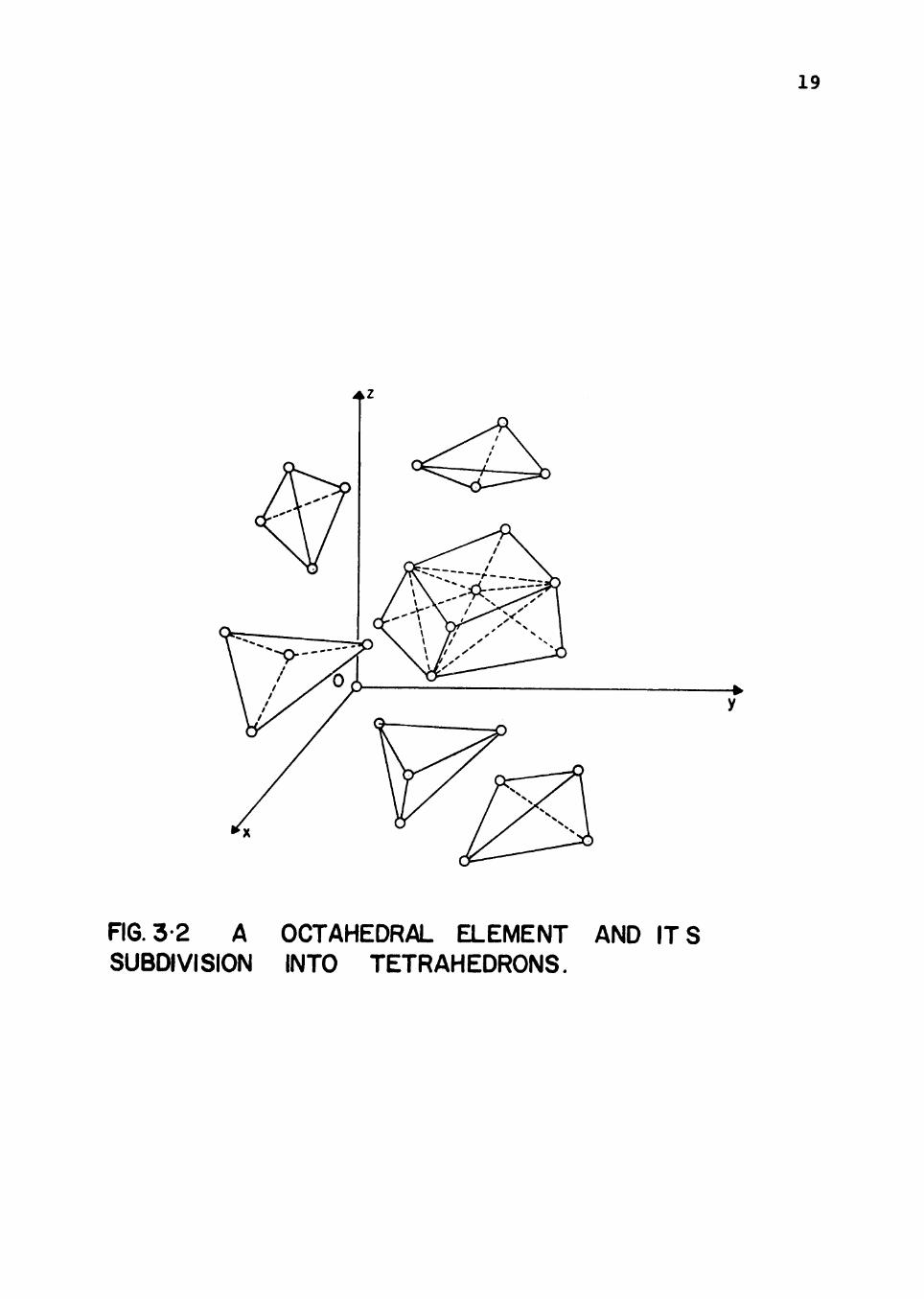
3.2 A Octahedral Element and its Subdivision
into Tetrahedrons 19
4.1 Model for Lumbar Spine 29
4.2 Displacement Configuration Due to Comp. Load 32
4.3 Displacement Configuration Due to Comp. Load 32
4.4 Displacement Configuration Due to Comp. Load 33
4.5 Displacement Configuration Due to Comp. Load 33
4.6 Displacement Configuration Due to Comp. Load 34
4.7 Displacement Configuration Due to Comp. Load 34
4.8 Displacement Configuration Due to Comp. Load 35
4.9 Displacement Configuration Due to Comp. Load 35
4.10 Displacement Configuration Due to Moment 38
4.11 Displacement Configuration Due to Moment 38
4.12 Displacement Configuration Due to Moment 39
V
FIG. Page
4.13 Displacement Configuration Due to Moment 39
4.14 Displacement Configuration Due to Moment 40
4.15 Displacement Configuration Due to Moment 40
4.16 Displacement Configuration Due to Moment 41
4.17 Displacement Configuration Due to Moment 41
4.18 Displacement Configuration Due to Torque 4 3
4.19 Displacement Configuration Due to Torque 4 3
4.20 Displacement Configuration Due to Torque 44
4.21 Displacement Configuration Due to Torque 44
4.22 Displacement Configuration Due to Torque 45
4.23 Displacement Configuration Due to Torque 45
4.24 Displacement Configuration Due to Torque 46
4.25 Displacement Configuration Due to Torque 46
4.26 Oi (psi) Distribution in the Disc Due to Comp. Load 48
4.27 ai (psi) Distribution in the Disc Due to Moment 49
4.28 Oz (psi) Distribution in the Disc Due to Torque 50
VI
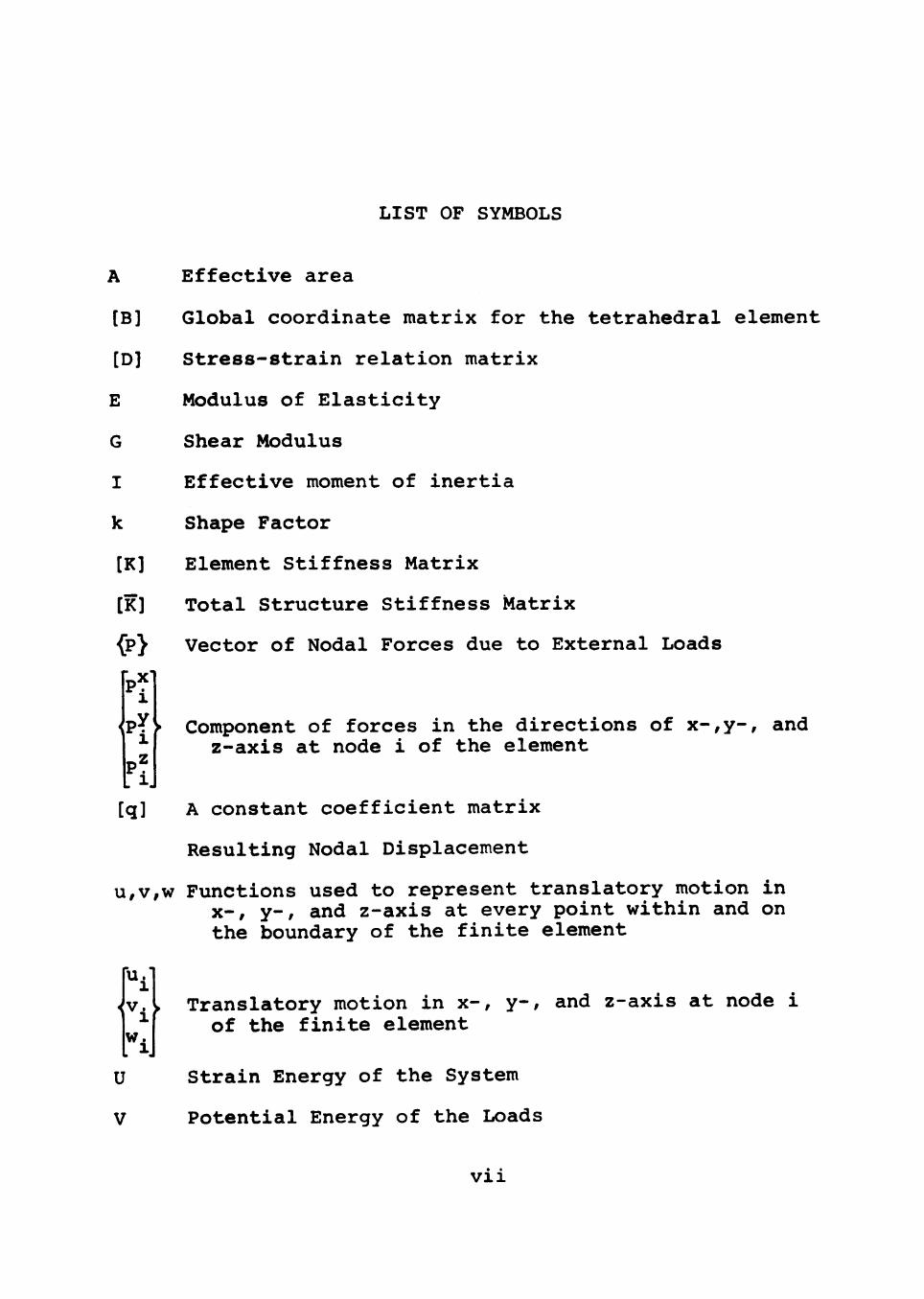
LIST OF SYMBOLS
A Effective area
[B] Global coordinate matrix for the tetrahedral element
[D] Stress-strain relation matrix
E Modulus of Elasticity
G Shear Modulus
I Effective moment of inertia
k Shape Factor
[K] Element Stiffness Matrix
[K] Total Structure Stiffness Matrix
^p} Vector of Nodal Forces due to External Loads
1
P Y > Component of forces in the directions of x-,y-, and ^ z-axis at node i of the element
p? 1.
[q] A constant coefficient matrix Resulting Nodal Displacement
u,v,w Functions used to represent translatory motion in X-, y-, and z-axis at every point within and on the boundary of the finite element
"ii v.y Translatory motion in x-, y-, and z-axis at node i
of the finite element "ij
U Strain Energy of the System
V Potential Energy of the Loads
VI1
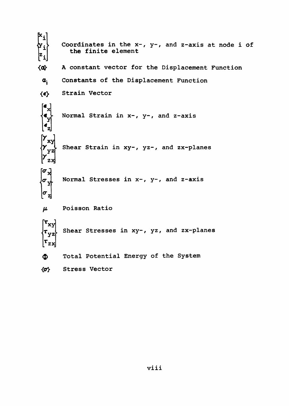
p'i i Coordinates in the x-, y-, and z-axis at node i Of the finite element
icQ' A constant vector for the Displacement Function
Gj Constants of the Displacement Function
{€ Strain Vector
I XI Normal Strain in x-, y-, and z-axis
' xy
^ZXI
- Shear Strain in xy-, yz-, and zx-planes
Normal Stresses in x-, y-, and z-axis
\
^xy
^yz
Poisson Ratio
. Shear Stresses in xy-, yz, and zx-planes
'zx
^ Total Potential Energy of the System
<a> Stress Vector
• • • Vlll
CHAPTER I
INTRODUCTION
Stress analysis of the human body is becoming more
and more important to engineers and labor organizations in
their efforts to protect the body from serious injuries
during work. Studies of the performance of the human body
under working conditions are undertaken by engineers in
cooperation with medical scientists and constitute a new
field of engineering known as Biomechanics Engineering.
The components of the human body have complex geome
try and material properties which are similar to components
encountered in Civil Engineering type structures. Using
the finite element techniques engineers analyze structures,
which have linear or non-linear, isotropic or anistropic
material properties. Many biomechanics problems deal with
stresses and strains in the human body caused by external
and internal forces. Knowledge of these stresses and
strains can be obtained by the finite element method pro
vided loads can be determined and properties of constituent
materials are known. Examples of these types of problems
are:
1. Stress analysis of a spine considering it as a three dimensional structure.

2. Stress analysis of the human skull considering it as a thick shell structure.
The objective of this thesis is to investigate the
usefulness of the Finite Element method for determining
stresses and displacements inside an individual human
vertebrae and the intervertebral discs which are integral
parts of the spine for certain external forces on the
spine. The fourth and fifth lumbar vertebrae and the
intervertebral disc were chosen for the analysis because
over 50 percent of specific low back injuries (herniated
discs) were reported at this segmental level by Peacock (1)
in 1950, Walmasley (2) in 1953, and Tondury (3) in 1958.
The finite element method is used to determine the
stresses and strains in the vertebrae and the interverte
bral disc. This method is relatively new in matrix
structural analysis and is very similar to the well known
Ritz procedure to solve boundary value problems in con
tinuum mechanics. This method of analysis requires the
use of an electronic computer because of the large number
of computations involved.
Review of Previous Research
There have been several previous investigations on
the behavior of the human spine. Elward (4) in 1939 com
pleted an historical review of the investigations on the
entire human spine. Studies of the cervical spine were
reviewed by Lysell (5) in 1969. Investigations on the
thoracic spine were summarized by White (6) in 1969, and
observations on the lumbar spine were discussed by Rolander
(7) in 1966.
Recent attempts have used principles of statics and
dyncunics to determine maximum weights to be handled by
individuals. In these approaches the human body is treated
as a system of solid links and joints. Using a few basic
assumptions, principles of mechanics can be applied to the
entire system once the physical characteristics of the
links (mass, center of mass, volume, density, and moment
of inertia) are known.
The reactive forces developed at the joints when
lifting a load were calculated by Morris, et al (8) in
1961 by using the link concept. These reactive forces can
be compared to the voluntary reactive forces (standard
values recommended by the International Labor Organization)
generated at the joints. Voluntary forces are the forces
which an individual can afford to resist without damaging
any part of his body. If the reactive forces at a joint
due to the lifting of a load exceed the voluntary reactive
forces then such a load should not be lifted. This
approach was used by Chaffin (9, 10) in 1967 and 1968,
and by Fisher (11) in 1967.
The assumption that the spine is a solid body is
usually made to simplify the analysis. In some loading
cases this assumption results in compressive stresses in
the rigid spine representation that far exceed the limits
of the biological material comprising the spine. The
basic assumption that the spine can be treated as a rigid
body can be judged intuitively to lead to inaccurate
results.
Bradford and Spurling (12) in 1945 assumed that the
spine and the back muscles operate as a crane. They found
that the static axial load could be as high as 1600 pounds
on the lumbar region of the spine when lifting with a
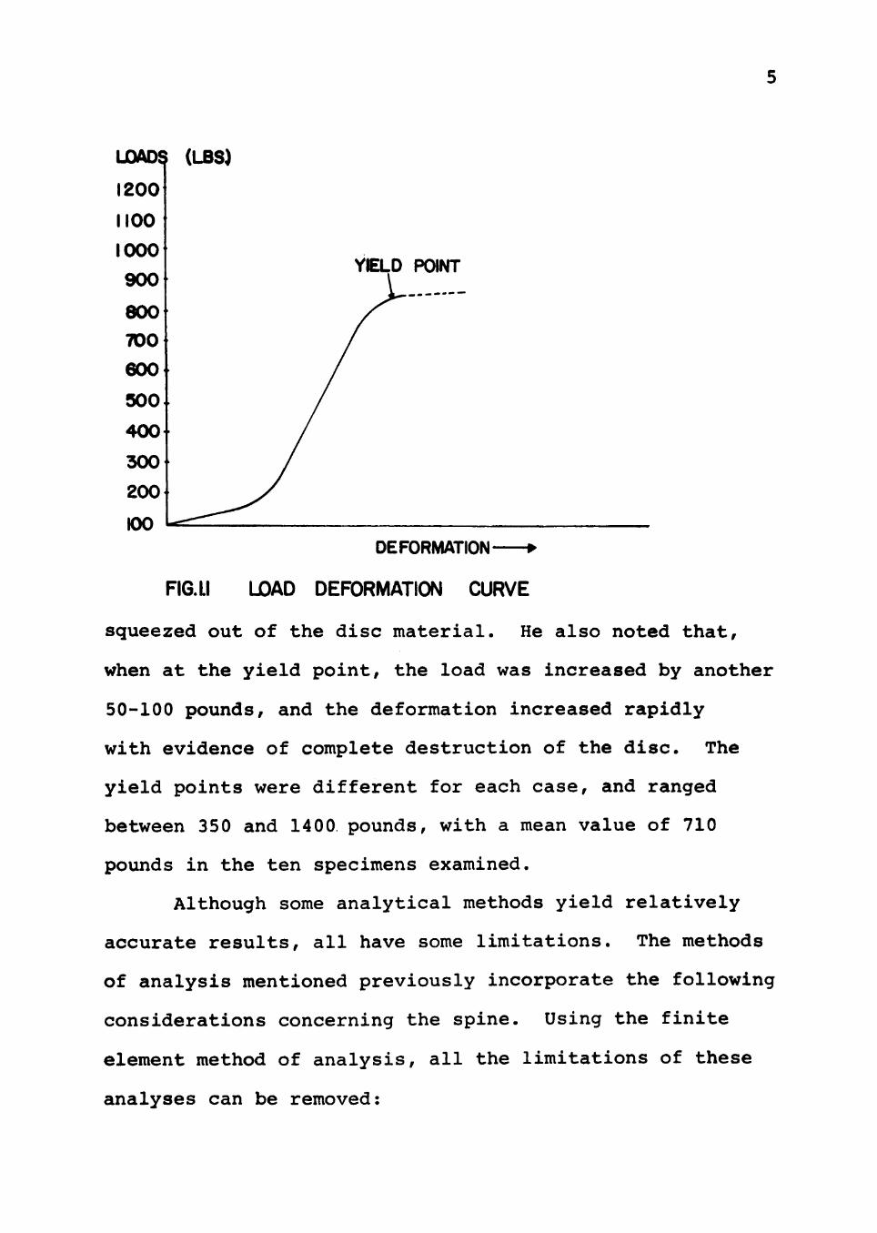
flexed back. Bartelink (13) in 1957, studied ten speci
mens of intervertebral disc between two nearly complete
vertebral bodies. These specimens, which were one-half
to two days old, were subjected to accurately measured
loads in a material testing machine. For each increment
of load, the deformation of the system was measured
accurately. All of the specimens behaved in the scime way
as shown in Fig. 1.1.
Initially there was a region of settling, where the
deformation was rather great relative to the increase in
load. This was followed by a straight part of the curve
where the disc essentially behaved as a linear-elastic
body, i.e., the deformation was increasing proportionally
to the load. Bartelink also noted that, during the linear
response, if the load was held constant for a considerable
length of time, the deformation increased very slowly.
This may be due to the flow of minute quantities of fluid
UOAD^ (LBS)
1200
YELD POINT
DEFORMATION
FIG. LI LOAD DEFORMATION CURVE
squeezed out of the disc material. He also noted that,
when at the yield point, the load was increased by another
50-100 pounds, and the deformation increased rapidly
with evidence of complete destruction of the disc. The
yield points were different for each case, and ranged
between 350 and 1400 pounds, with a mean value of 710
pounds in the ten specimens examined.
Although some analytical methods yield relatively
accurate results, all have some limitations. The methods
of analysis mentioned previously incorporate the following
considerations concerning the spine. Using the finite
element method of analysis, all the limitations of these
analyses can be removed:
1. To consider human spine a non-rigid structure,
2. The effects of different elastic constants for the different portions of the spine system, amd
3. The sudden change in cross-section of the system (vertebrae to disc).
Of all conventional methods, it is the author's
opinion that the finite element method is the best one
currently available for the stress analysis of the lumbar
spine. «
Finite Element Method
Early literature concerning the finite element
method is found predominantly in aeronautical engineering
publications. However, there has been considerable uti
lization of the method in many problems in civil, mechani
cal, and even electrical engineering in recent years.
The analysis of the spine is performed by dis-
cretizing the spine into a finite number of solid elements.
Since the lumbar spine problem is three dimensional in
nature, three dimensional finite elements must be employed.
These elements, which have finite dimensions and have the
same physical properties as the material in the continuum
that they represent, are assembled to approximate the
overall continuum. A detailed description of the theory
of the finite element method is given in Chapter III.

Scope of the Research
The main objective of this research is to investi
gate the usefulness of the finite element method in cal
culating the stresses and strains in the human spine
under various simple loading conditions.
The low back—the fourth and fifth vertebra and the
intervertebral disc—is used as a system representative of
the lumbar spine. A simplified physical model is used in
which no ligament attachments are considered. The descrip
tion and size of the physical model is presented in
Chapter IV.
CHAPTER II
LUMBAR SPINE PROBLEMS
An important aspect of man's load carrying operation
is the risk of the structural injury, in particular to
the musculoskeletal structure of the back. Low back
injuries are among the major causes of absenteeism in
industry and account for much disability in industry as
well as at home. The U.S. Department of Labor booklet
entitled Teach Them To Lift, says, "The problem of
injuries resulting from the manual handling of material
continues to plague industry. The accident preventionist
still seeks to reduce the toll of this type injury by
setting broad brush restrictions on how much a person
should be permitted to lift. . . .Everyone is searching
for a solution. . . .Unfortunately, there is no easy way
out."
It is highly desirable to know the maximum permis
sible weight to be carried by a given worker and to know
some specific safety methods of lifting and carrying so
that injuries may be minimized. Several investigations
on this subject have given rise to some specific safety
methods of lifting. A common feature of this advice is
that lifting by bending the trunk with the knees straight
8
is more dangerous than the method of lifting with flexed
knees and upright trunk. Floyd and Silver (14) in 1955
pointed out that the knee action minimizes strain to the
posterior ligaments of the spine.
The vertebrae, the intervertebral discs, the related
ligaments, the muscles and nerve roots are the components
of the lower part of the back. The causes of backache
are either intrinsic, i.e., structural, mechanical, or
pathological, or extrinsic, i.e., related to the environ
ment and the external forces acting upon the back.
The lumbar vertebrae are the largest segments of
the movable part of the spine. It may be considered that
the human vertebrae are comprised of two parts firmly
joined together: the vertebral body and the neural arch.
The vertebral body is a more-or-less elliptical column of
joints, the facet joints between the neural arches. The
joints are secured around their priphery by a ligamentous
capsule. Both sides of the neural arch are joined to
the ligamentum flavum by elastic ligaments. The inter
vertebral joint therefore consists of an anterior portion,
the disc and its longitudinal ligaments, the posterior
portion including the two facet joints and the various
ligaments joining the neural arches.
Dimensions of the Lumbar Spine
The fourth and fifth lumbar vertebrae and the inter
vertebral disc between them is shown in the Fig. 2.1.

10
A = OVERALL LENGTH OF VERTEBRAE
IN SAGITTAL BODY PLANE (MEASURED)
B= SAGITTAL PLANE DIAMETER OF
INTERIOR SURFACE OF L5 VERTEBRAE
(MEASURED)
C=POSTERIOR SPINOUS PROCESS AND
NEURAL ARCH DEPTH
(CALCULATED: C = A - B )
FIG. 21 GEOMETRIC MEASUREMENTS
11
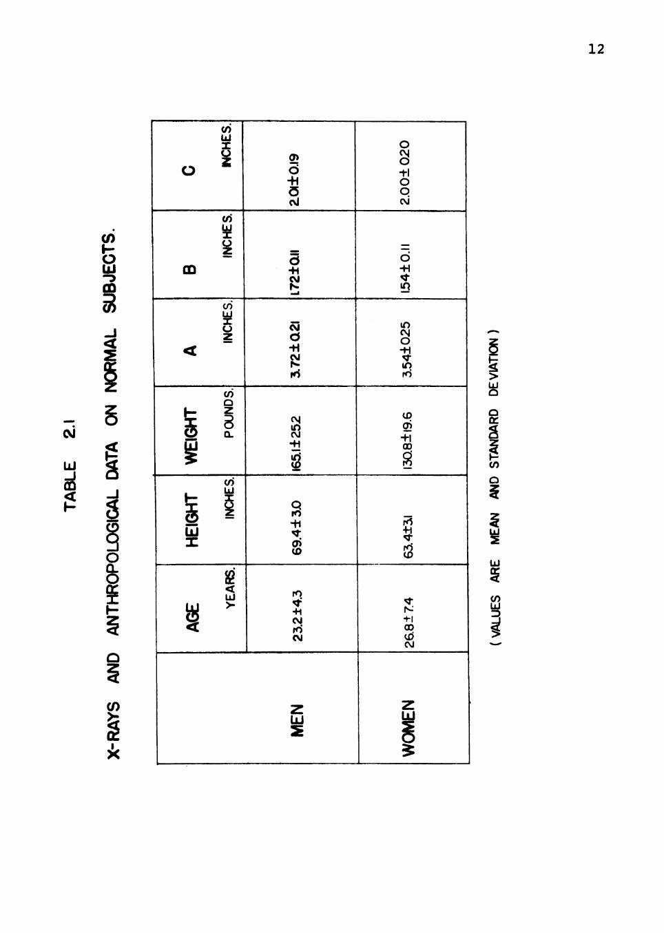
These linear dimensions were measured using precision
machinists calipers by Chaffin (17) in 1968, and x-rays
of normal h\iman beings (who are referred to as subjects).
The subjects were positioned with their hips flexed to a
90° position in respect to the long axis of the trunk.
Samples for men and women were taken to establish normal
values. All persons sampled had passed a medical exeunina-
tion which included radiological studies for outstanding
spinal anomalies. The samples studied included fifty men
and fifty women and were selected randomly from a file of
over 10,000 x-ray photographs made during a five-year
period at the Western Electric Company Works in Lee's
Summit, Missouri. The result is summarized in Table 2.1.
Material Properties of Lumbar Spine
Although Evans and Lissner (18) in 1959, reported
information on the behavior of the lumbar spine in bending
and shear, they gave only load/deflection data. However,
from their load/deflection data, Orne and Liu (19) in
1970, estimated the bending stiffness, EI, and the effec
tive shear stiffness, GA/kl, where A and I are effective
area and the moment of inertia of the vertebral body, and
k is a shape factor. They also estimated the shape factor
of the disc as k = 1.5, with the disc height of 0.48 inches.
They calculated the values of elastic constants G, E, and
ft for the disc as 2200 psi, 6600 psi and 0.50 respectively.
12
CM
UJ
^
o
CD
<
GHT
W
EI
h-
IGH
UJ X
^ <
<n UJ X ^
a> UJ X
INC
CO
INCH
E
(O o
POU
N
(/) UJ
i
!2
YE
A
0>
d -H S (Vi
5 ••1 CM N _ i
-H CM ^* Hi
252
Q ro -h ^ a> 0)
2 ±4
.3
fO CM
Z UJ 2
o s i-l o o CM
O.ll
-H ^ !Q
in CM o ^ in ro
130.
8+19
.6
r<1 +1 ^ i^K 8
±7.4
00
CVJ
Z UJ
^
a: s
o
UJ
2 UJ
s UJ
i
13
But in 1970 Farfan, et al (20) independently computed dif
ferent values of G, E, and //. for the disc: 790 psi,
2200 psi and 0.40. Farfan and his associates conducted
their experiments on a separated disc. Farfan used the
same elastic constants for vertebral as those of bone; 5
the values for G, E, and /x. are 38,500 psi, 10 psi and
0.30.
CHAPTER III
THE FINITE ELEMENT METHOD
The finite element method is a technique that has
been successfully used for analyzing solid continua
where the material has linear or non-linear properties.
During the last 15 years this method has become an
extremely useful and versatile tool for analyzing complex
structural problems.
The finite element concept, originally introduced
by Turner, et al (21) in 1956, was first applied by
Clough (22) in 1960 to civil engineering problems. How
ever, as early as 1927 Hrennikoff (23) and McHenry (24)
had discussed a lattice analogy concept similar to the
present finite element concept to represent the continuum.
Clough's concept of the finite element method became
popular among engineers because of its convenience in
handling the complex geometry of the continuum.
The popular approach in finite element analysis is
based on the displacement characteristics of the system.
The basic operations employed in the displacement approach
to analyze a solid continuum are:
1. Development of continuous displacement functions to represent the displacements at any point
14
15
within the element such that the functions satisfy the compatibility requirements among adjacent elements.
2. Development of a stiffness matrix of an arbitrary element with respect to a local coordinate system.
3. Development of a transformation matrix to transform the stiffness matrix from a local coordinate system to a global coordinate system, and generation of the global stiffness matrix [K]. Superposition of the transformed element stiffness matrices result in the formulation of a set of linear simultaneous equations of the form:
[K] <:u>= [P] . . . (3.1)
where {u)-is the global displacement vector and [P] is the corresponding global force vector.
4. Incorporation of the displacement boundary conditions of the system in equations (3.1).
5. Solution of the system of the linear simultaneous equations (3.1) for the unknown nodal displacements.
6. Calculation of internal stresses and strains resulting from the nodal displacements.
The concept for using an element having the shape
of a tetrahedron to represent a three-dimensional solid
was made by Martin (25) in 1961, and independently by
Gallaghar, et al (26) in 1962. This tetrahedral element
is the three-dimensional counterpart of the original con
stant strain triangle for plane stress analysis developed
by Clough, et al (22). In 1963, Melosh (27) proposed an
element in the form of a rectangular prism, which is the
three-dimensional counterpart of a simple rectangular
plane stress element. Melosh also studied the properties

16
of this simple prism, as well as a similarly shaped ele
ment formed by assemblage of five tetrahedrons. Out
standing work in the development of a general computer
program for three-dimensional finite element analysis was
done by Cornell, et al (28). These elements have been
used to solve many practical three-dimensional problems
(29, 30).
The element used in this thesis to represent a three*
dimensional continuum is a tetrahedral element. A typical
tetrahedron is considered as a single finite element with
three degrees of freedom at each nodal point. Thus, there
are 12 degrees of freedom per element. This element is
completely identified by its material properties and the
coordinates of its nodal points. A typical tetrahedron
element is shown in Fig. 3.1 using cartesian coordinates
system (x, y, z), where u, v and w represent the corre
sponding displacements at any general point within the
element. The material properties of each element are
assumed to be linear, isotropic and homogeneous. The
element stiffness matrix for a typical element is formu
lated as discussed previously.
If the structure has complex geometry, the actual
modeling of the structure with tetrahedrons becomes
difficult. To overcome this difficulty it is necessary
to use a combinational routine which automatically

17
,w
x,u
FIG.3I A TETRAHEDRON FINITE ELEMENT.
18
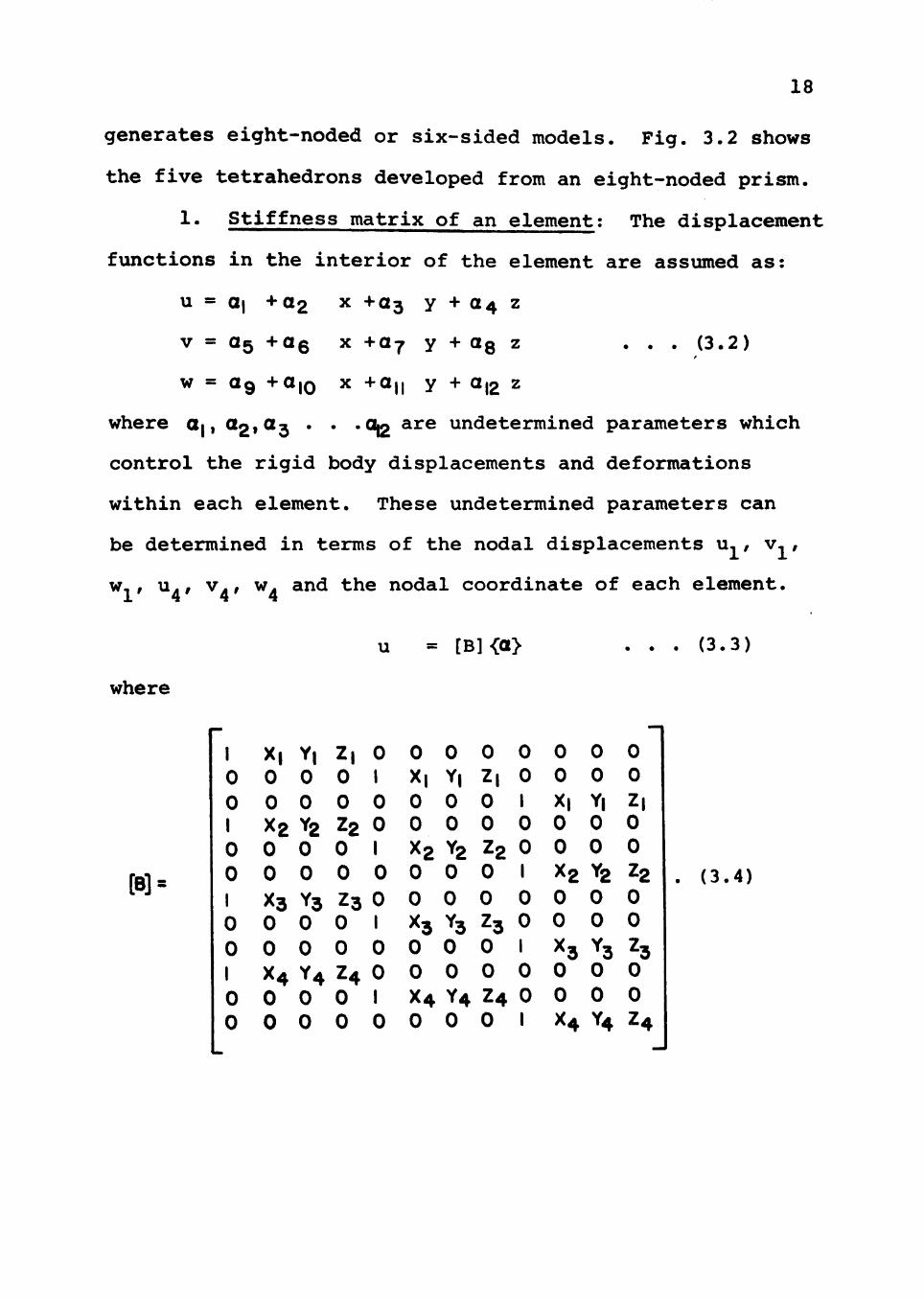
generates eight-noded or six-sided models. Fig. 3.2 shows
the five tetrahedrons developed from an eight-noded prism.
1. Stiffness matrix of an element: The displacement
functions in the interior of the element are assumed as:
u = Qj +02 X +03 y + 04 z
V = 05 +06 X +07 y + OQ z . . . (3.2)
w = 09 +a,o X +a,| y + a,2 z
where Oj, az^OL^ * * * % ^^^ undetermined parameters which
control the rigid body displacements and deformations
within each element. These undetermined parameters can
be determined in terms of the nodal displacements u,, v,,
w,, u., v., w. and the nodal coordinate of each element. 1 4 4 4
u = [B]<a> . . . (3.3)
where
[B] =
1 0 0 1 0 0 1 0 0 1 0 0
X, Y, Z, 0 0 0 0 1 0 0 0 0 X2 Y2 Z2 0 0 0 0 1 0 0 0 0
X3 Y3 Z3 0 0 0 0 1 0 0 0 0 X4 Y4 Z4 0 0 0 0 1 0 0 0 0
0 0 0 0 X, Y, Z, 0 0 0 0 1 0 0 0 0 X2 Y2 Z2 0 0 0 0 1 0 0 0 0
H Y3 Z3 0 0 0 0 1 0 0 0 0 X4 Y4 Z4 0 0 0 0 1
0 0 0 0 X| Y| 0 0 0 0 X2 Y2 0 0 0 0
H Y3 0 0 0 0 X4 Y4
0 0 Z| 0 0
22 0 0
Z3 0 0 Z4
(3.4)
19
R6.3-2 A OCTAHEDRAL ELEMENT AND ITS SUBDIVISION INTO TETRAHEDRONS.

20
in which <u> is a 12 x 1 column vector of undetermined
nodal displacements of the element, [B] is a 12 x 12
matrix, and <a> is a 12 x 1 column vector consisting of
undetermined parameters, i.e., coefficients of the assumed
displacement functions. Since the matrix [B] is non-
singular, <a> can be written in terms of [B] and u as:
<a> = [B]"-*- {u> . . . (3.5)
All six strain components are used in three-dimensional
analysis of a continuum. The strain vector consisting
of the six strain components can be related to the dis
placement as follows:
<€> =
Xzx
du/ dx
dv /dy
dw / dz
du /dy -4- &i/&i
dv/dz + dw/dy
dvf/dx + du/dz
. . (3.6)
Performing the differentiation on u, v, and w of equation
(3.2),

21
« '
0 1 0 0 0 0 0 0 0 0 0 0
0 0 0 0 0 0 1 0 0 0 0 0
0 0 0 0 0 0 0 0 0 0 0 1
0 0 1 0 0 1 0 0 0 0 0 0
0 0 0 0 0 0 0 1 0 0 1 0
0 0 0 1 0 0 0 0 0 1 0 0
ai 02
03
04 05 OS 07 OS 019 OlO an 0|2
U3.7)
or, in matrix notation
<€> = [q] {a> . . . (3.8)
Substituting the value of {O) from equation (3.5),
{€> = [q] [B]'^ <:u> . . . (3.9)
Corresponding to six components of strain at a
point, there are six components of stress at a point
represented by a stress vector {ay . The stress/strain
relationship for a linear, isotropic, and homogenous
material is given by the theory of elasticity (31) as:
«r> = <
< X
•fXY
TYZ T"ZX
> [D] <€>
• • • (3.10)

i n which [D] i s
22
E {^'H (l4/i)(l-2/i)
I /i/l-/t /i/l-/i, 0
I fl/\'fJL 0
i-^i/20-^O
l-£^i/20^O
t^tx/2M
. (3 .11)
Denoting t h e nodal f o r c e v e c t o r [P] corresponding t o
the nodal d i s p l a c e m e n t v e c t o r <u> a s :
[P] = < > . . . (3 .12)
4

23
The components P^^, P^^, and P^^ represent the nodal forces
at node 1 of the element in the direction of x, y, and z
axes respectively.
The basic principle of the finite element method is
the minimization of the total potential energy of the
system in a static equalibrium condition (33). This
minimization process is equivalent to the well known Ritz
procedure in solid mechanics.
The minimum potential energy function is defined as:
^ = U + V . . . (3.13)
where U is the elastic strain energy in the continuum and
V is the potential energy due to external forces. For a
linear system,
U = 1/2/<€>*«7> d(Vol.) . . . (3.14)
and V = -[P] <u> due to external forces . . . (3.15)
substituting for <€> and <o> from equations (3.9) and (3.10)
into equation (3.14),
U = l/2fiuy^ [[B]"^l*'[q]*'[D] [q] [B]'^<U>d(vol.) Jy ^ ^ . . . (3.16)
The principle of minimum potential energy states
that, "of all geometrically compatible displacement states,
those which also satisfy the force-balance conditions give
stationary values to the total potential energy^" (32).
To minimize the total potential energy <!> with
respect to the nodal displacements, a system of equations
is established such that:
24
d<I>/d<u> = 0 . . . (3.17)
Substituting the value of U from equation (3.16) into
equation (3.13) and performing the above differentiation,
the following relation is obtained:
J[[B]~^]^[q]^[D] [q] [B]" {u}d (vol.) - [P] = 0 . (3.18)
This can be written as:
[K] <u> - [P] = 0 . . . (3.19)
where [K] is the stiffness matrix of element and is given
by:
[K] = /[[B]"^]^[q]^[D] [q] [B]"^ d(vol.) . . . (3.20)
Equation (3.20) is the stiffness matrix equation of a
tetrahedron element. Since the matrices [B], [q] and [D]
are independent of the volume integration in equation
(3.20), the stiffness matrix for the element [K] becomes:
[K] = [[B]"^f [q]^[D] [q] [B]"^.V. . . . (3.21)
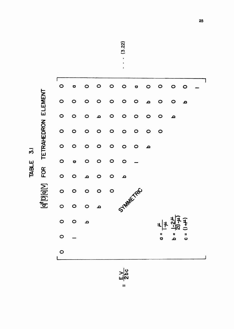
The coefficients of the matrix [q] [D][q][V] are given
in Table 3.1.
2. Stiffness matrix of the entire continuum. In
general, the accuracy of an element stiffness matrix can
be evaluated using a local coordinate system rather than
the global coordinate system of the entire continuum.
The stiffness of the element in the global coordinate
system is obtained by means of an appropriate transforma
tion. In the lumbar spine problem, however, the above
25
Z UJ
UJ -J UJ
O a: a UJ
Zi ^ ro
UJ
a!
UJ I -
cr o
CVJ CVI
ro
O o O O O O o O O O O —
O O O O O O O ^ O o
O O O ^ O O O O O jQ
o o o o o o o o o
O O O O O O O
O o O O O O —
O O x> O O X3
O O O O O
o o o ^
O O J3
^ < ^ *
CM C^ M M II
O A o
> ^ UJ CM
I I
26
mentioned transformation is not necessary because the
element stiffness matrix is computed using a pre-selected
global system.
Once the element stiffness matrix is available in
the global coordinate system, the assemblage of the stiff
ness matrix for the continuum is easily formed by super
posing the stiffness matrices of the individual elements
using the equilibrium conditions at each node. Then the
stiffness matrix of entire continuum becomes:
[K] {u} = [P] . . . (3.24)
where [K] is the stiffness matrix of entire continuum,
W and [P] are the corresponding global displacement and
force vector. The stiffness matrix [K] is always sym
metric and will be banded if the elements are properly
numbered. Therefore, for most large structural systems
only half of the banded stiffness matrix is stored on
the computer.
3. Incorporation of the prescribed boundary dis
placements. If the boundary displacements are not pre
scribed to arrest the rigid body motions of the whole
system, the stiffness matrix [K] obtained in equation
(3-24) is positive semi-definite. The required displace
ment boundary conditions are specified by adjusting the
global stiffness matrix coefficients and the components
of the global force vector.

27
^' Solution of the force-displacement equations.
After incorporation of the prescribed boundary displace
ments, the matrix equation results in a set of simultane
ous linear equations representing the overall system.
The matrix [K] is now positive definite. This linear,
banded system of the equations can be solved by Gauss
Elimination using only the half band width (33). In order
to deal with a large number of unknowns, the equations are
stored in blocks on a disc as they are generated. Gauss
Elimination is carried out block by block and then stored
back on a disc. During back substitution, each block is
recalled and the unknown displacements computed. Gaussian
Elimination is utilized herein because of advantages of
reduced storage requirements and fewer computations com
pared to other methods of solving simultaneous equations.
5. Calculation of internal forces. Using the nodal
displacements of each element, the internal strains and
stresses are calculated. In most instances the stresses
are of primary importance to the design engineer.

CHAPTER IV
ANALYSIS OF LUMBAR SPINE
The lumbar spine, as described previously, is the
largest segment of the movable part of the spine and is
susceptible to severe injuries during lifting or other
working operations. This investigation, therefore, is
concentrated on the determination of stresses and dis
placements on the joint of vertebrae and intervertebral
disc under different conditions of load such as compres
sive load, moment, and torque.
Bartelink (13) found that the values of load which
damaged the system varied from 350 pounds to 1400 pounds.
This value is for axial compressive load only. In the
absence of critical values for loads such as axial load,
bending moment and torque to be applied on the lumbar
spine, arbitrary values of 1000 pounds, 1000 in. pounds,
and 1000 in. pounds were selected for axial load, bending
moment and torque respectively in this research.
A model of this portion (fourth and fifth vertebrae
and intervertebral disc between them) was developed and
is shown in Fig. 4.1. The simplification of the lumbar
spine shown in Fig. 4.1 has been made because the elastic
28

ro
6
. .
to
1-63
1-23'
FOURTH LUMBAR VERTEBRAE
INTERVERTEBRAL DISC
E2»^2
FIFTH LUMBAR VERTEBRAE
E| t Ml
FIXED BOUNDARY
29
SCALE 1/2"= l"
R6.4I MODEL FOR LUMBAR SPINE

30
constants of vertebrae are larger than the intervertebral
disc, and the dimensions of the disc are small compared
to those of the vertebrae. Thus exact dimensions of the
intervertebral disc are not necessary for stress analysis
in the disc.
To study the effect of the variation in the material
properties of the vertebrae and the intervertebral disc,
it was necessary to analyze the deformations and the
stresses of the system for different elastic constants
as illustrated in Figs. 4.2 to 4.9. As the number of
finite elements used for discretization of a continuum
increases, the behavior of the numerical finite element
model becomes closer to that of the prototype. It is
obvious that the subdivision pattern of the continuum
plays an important role in the convergence process. How
ever, the analyst is limited in the degree of fineness
for division of the continuum by the storage available on
the computer and the possibility of round off errors
generated in the computer. One way of dealing with round
off errors in the solution of large numbers of equations
is to use double precision arithmetic whenever possible.
However, this technique has the same limitations discussed
before. Thus it is necessary to study the characteristics
of the deformation patterns of the finite element model
as the number of equations of the system is increased.
For this reason the lumbar spine system is discretized in
31
different ways and solved and the results are presented
in a series of figures for the three loading conditions
discussed earlier.
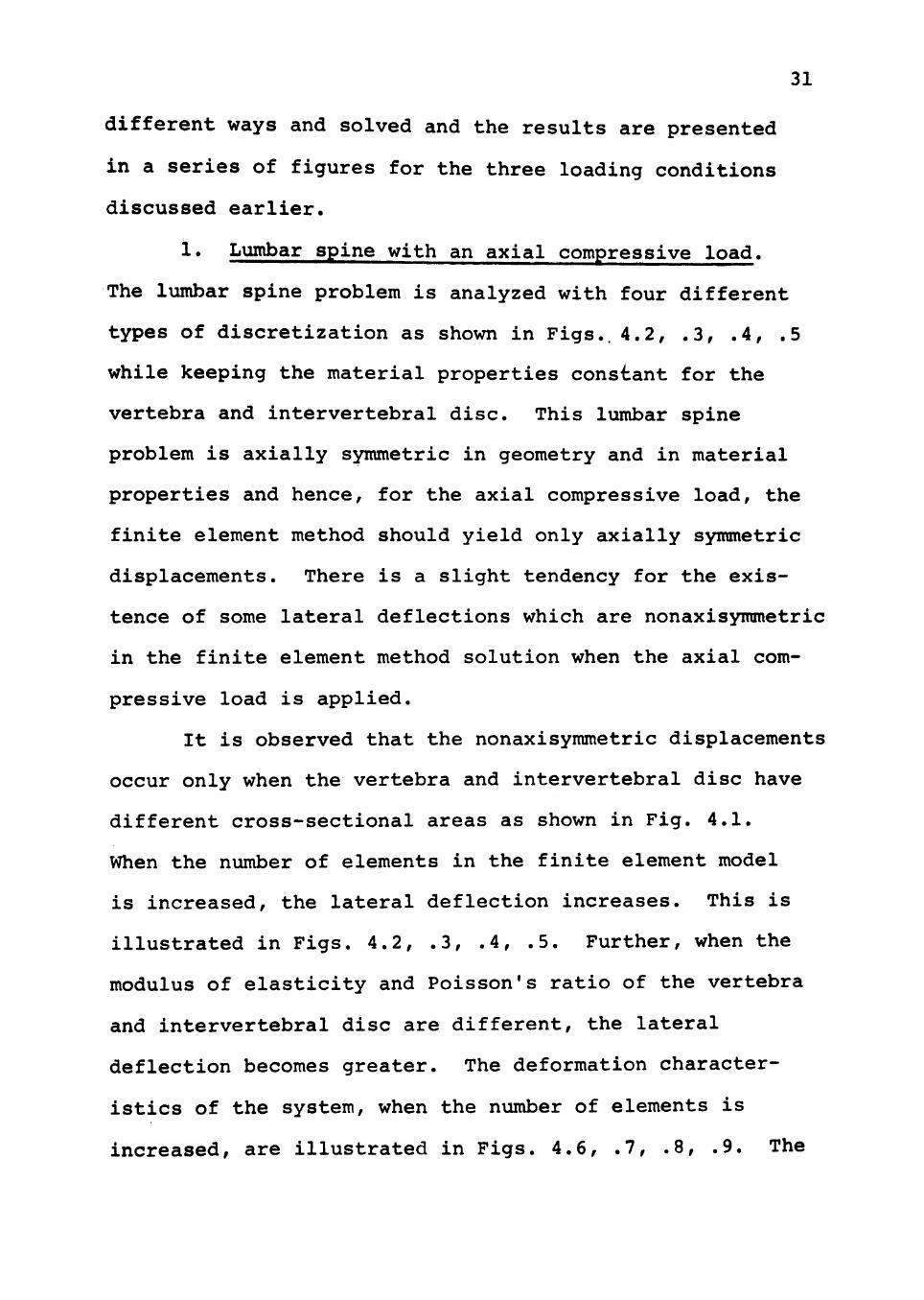
!• Lumbar spine with an axial compressive load.
The lumbar spine problem is analyzed with four different
types of discretization as shown in Figs.. 4.2, .3, .4, .5
while keeping the material properties constant for the
vertebra and intervertebral disc. This lumbar spine
problem is axially symmetric in geometry and in material
properties and hence, for the axial compressive load, the
finite element method should yield only axially symmetric
displacements. There is a slight tendency for the exis
tence of some lateral deflections which are nonaxisymmetric
in the finite element method solution when the axial com
pressive load is applied.
It is observed that the nonaxisymmetric displacements
occur only when the vertebra and intervertebral disc have
different cross-sectional areas as shown in Fig. 4.1.
When the number of elements in the finite element model
is increased, the lateral deflection increases. This is
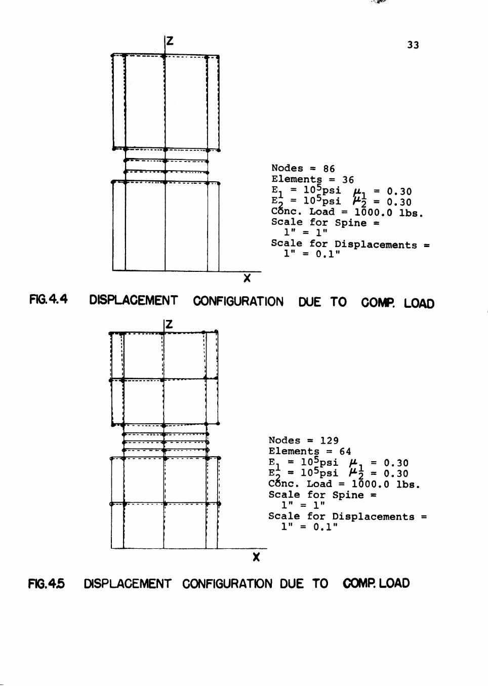
illustrated in Figs. 4.2, .3, .4, .5. Further, when the
modulus of elasticity and Poisson's ratio of the vertebra
and intervertebral disc are different, the lateral
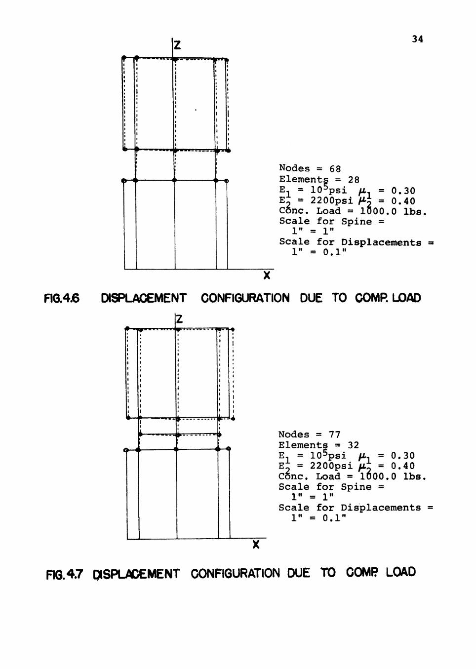
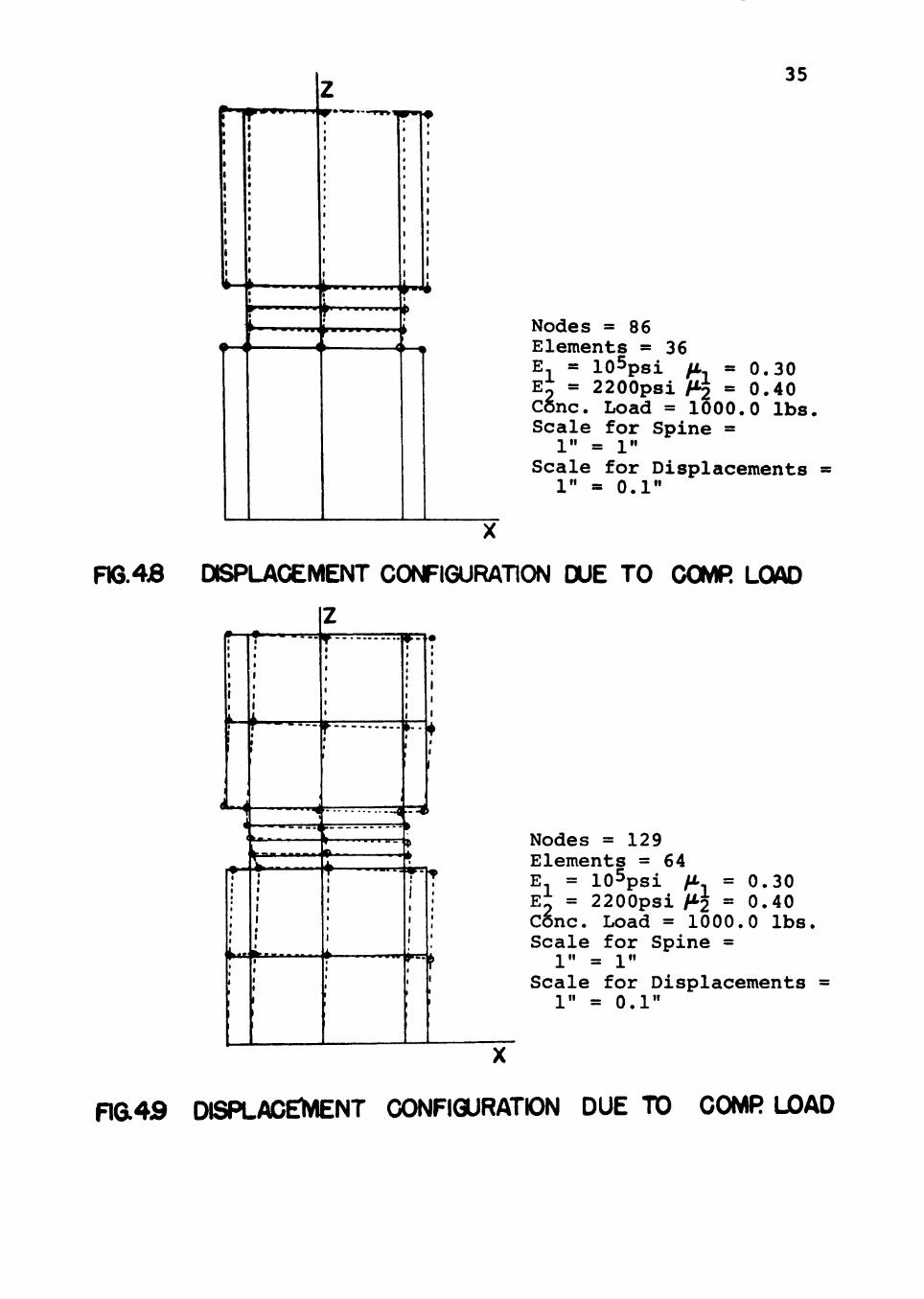
deflection becomes greater. The deformation character
istics of the system, when the number of elements is
increased, are illustrated in Figs. 4.6, .7, .8, .9. The

1 i 1
j
•
4- ~ ^ ^ . - \ 1 • : 1
< I
i 1
z 1 < 1
1
; 1 1 1 1 1 1 1 1 I 1
^ —r ! :
: i ^ r , $ 1 * ( 1
1
1 t 1 > 1 1 • 1 > 1
i
>«
- •
32
Nodes =68 Elements =28 E = lO^psi/i, . = 0.30 E2 = lOSpsi /I 2 = 0.30 Cone. Load = 1000.0 lbs Scale for Spine = 1" = 1"
Scale for Displacements 1" = 0.1"
Fia4.2 DISPLACEMENT CONFIGURATION DUE TO GOMR LOAD
f ^
frrnr
tfF=^P
W^
TT^
Nodes = 7 7 Elements = 32 E. = l O ^ p s i fJL^ = 0 .30 E^ = lOSpsi fL2 = 0 .30 Cone. Load = 1000.0 lbs. Scale for Spine = 1" = 1"
Scale for Displacements = 1" = 0.1"
FIG. 43 DISPLACEMENT CONFIGURATION DUE TO COMP LOAD
•w^
™J
— . . L I J^ p ' t 1!
33
Nodes = 86 Elements = 36 E- = lOSpsi fi = 0 .30 ••' = l o S p s i H-l = 0 .30
lbs. E C5nc. Load = 1000.0 Scale for Spine = 1" = 1"
Scale for Displacements 1" = 0.1"
FIG.4.4 DISPLACEMENT CONFIGURATION DUE TO COMR LOAD
1 1
1 1 1 1
1 1 1
I
1
1
1 1 1
< « <
(
<
h--«
^ „
1 1 t 1
. 4 1
1
1
1
• * — — — W B ^ ^
t- H
»• - • « >• •<
> - -
1
» - -
1
z
• -
r k -
1 1 b 1
1
1
( 1 1
1
'
* 1
ft !»
1 1
r--
1
1
1
( 1
I 1
1 1
E = lOSpsi fi = 0. si = lOSpsi H-o = 0.
Nodes =129 Elements =64 E ^2 = iU-'psi r-2 Cone. Load = 1000.0 Scale for Spine =
1" = 1" Scale for Displacements
1" = 0.1"
30 30 lbs.
FIG.45 DISPLACEMENT CONFIGURATION DUE TO COMR LOAD
z 1 - • ' •
i
1 1 1 1
* 1 1 1
1
1
1
1 1
1 1
1 t 1 1 1 1 1 I 1 • 1 1 1 1 1 1 1
1 1 1 1
• •
1
1 1 1
1 1 1 1
1
1
1
1 • 1
1 ( 1
1 t
•
1
r 1 1 1
34
Nodes = Elements E, = 10-
68 ; = 28 psi /i
E^ = 2200psi H-i = = 0.30
0.40 C6nc. Load = lOoO.O lbs. Scale for Spine =
1" = 1" Scale for Displacements
1" = 0.1"
RG.4.6 DISPLACEMENT CONFIGURATION DUE TO COMR LOAD
• • • » • - J ^
^ — < • 4 H - 0
Nodes = 7 7 Elements = 32 E, = 105psi /t. = 0.30 E^ = 2200psi /Ij = 0.40 Cone. Load = 1000.0 lbs Scale for
1" = 1" Scale for
Spine =
Displacements 1" = 0.1"
RQ.4.7 PISPLADEMENT CONFIGURATION DUE TO COMP LOAD
Li 9-H
»»»"»»Jt»»nrw-.-
< • — *
35
Nodes = 86 Elements = 36 E. = lOSpsi /x. = 0.30 E^ = 2200psi /^ = 0.40 Cone. Load = 1000.0 lbs. Scale for Spine = 1" = 1"
Scale for Displacements • 1" = 0.1"
FIQ.4B DISPLACEMENT CONFIGURATION DUE TO COMR LOAD
<•••(
t —
X
wn»
-^--4
~'" —"—'
« ^
Nodes = 129 Elements = 64 E = 105psi ft. = 0.30 E^ = 2200psi M2 = 0-40 Cone. Load = 1000.0 lbs. Scale for Spine = 1" = 1"
Scale for Displacements = II _ 0.1"
n a 4 S DISPLAOEI^NT CONFIGURATION DUE TO COMR LOAD
36
mathematical finite element model of the lumbar spine is
subjected to the necessary boundary displacement condi
tions to stop rigid body displacements, which makes the
stiffness matrix nonsingular. It is difficult at this
time to explain mathematically the reasons for the lateral
deflection obtained in the finite element solution. How
ever, in the author's opinion this nonsymmetric solution
is due to the ill-condition of the stiffness matrix when
the area of cross-section and the material properties of
the vertebra and the intervertebral disc are different,
and due to the imperfections in the discretization of the
finite elements.
A real- lumbar spine system has additional supports
from the surrounding muscles and the abdominal fluid
pressure. If one considers these additional support condi
tions for the finite element model of the lumbar spine,
it is possible that the misalignment behavior exhibited
in the finite element solution may not exist. Additional
research effort to include these conditions are hence
necessary.
The nonaxisymmetric deflections of a lumbar spine
system are referred to as misalignment of the system by
researchers in Biomechanics. Physically, it is possible
to observe a misalignment of the lumbar spine system
even under axisymmetric loading conditions. Chaffin,
et al (10) has noticed the existence of a misalignment of
37
the system under axial loading conditions, and explains
that the axial load is decomposed into axial and shearing
components. Fig. 4.9 demonstrates clearly the existence
of large shear strains in the intervertebral disc as could
be expected in a real lumbar spine system. However, at
this time, it is not recommended that the results of a
misalignment from the finite element model be compared
with that of a physical model.
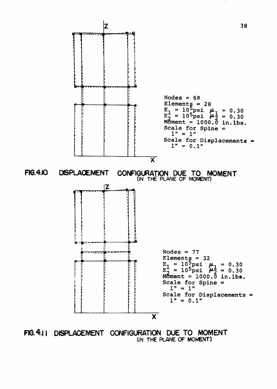
2. Lumbar spine subjected to moment. The lumbar
spine system is discretized and the analysis is repeated
as before by keeping the modulus of elasticity and
Poisson's ratio same for the vertebrae and intervertebral
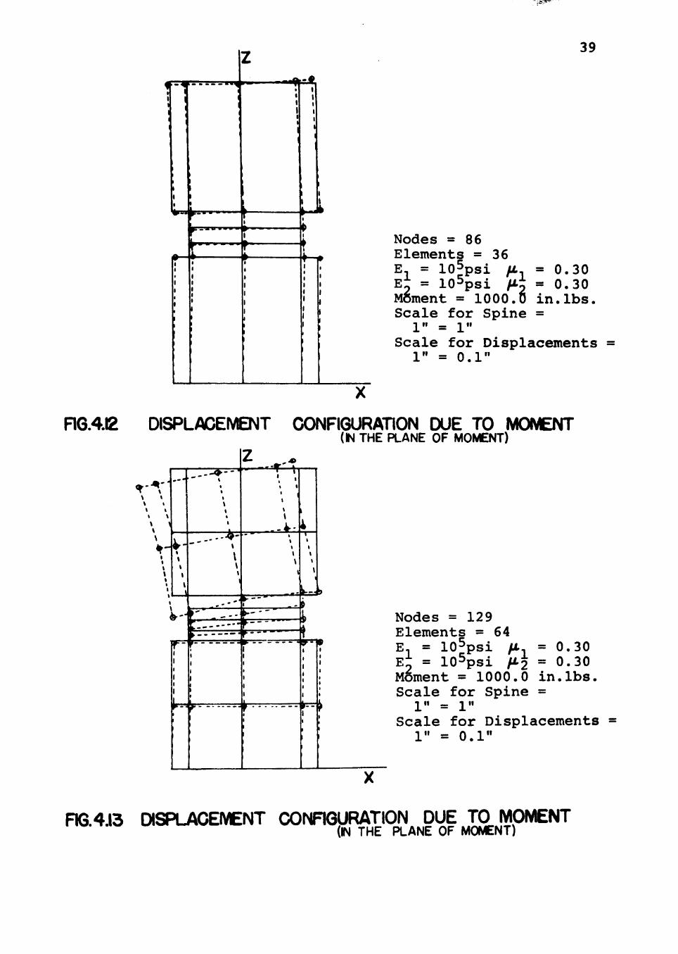
disc. The deformation patterns are shown in Figs. 4.10,
.11, .12, .13. Naturally, some tensile stresses are
noticed in the vertebrae and the disc.
Again the moduli of elasticity and Poisson*s ratios
are kept different for the vertebrae and the intervertebral
disc, and the resulting deformation characteristics are
shown in Figs. 4.14, 15, .16, .17. Again, some tensile
stresses were developed in the vertebrae and the inter
vertebral disc due to the externally applied moment. In
reality, the ligaments that connect the vertebrae and the
intervertebral disc are capable of resisting these tensile
stresses (19).
3. Lumbar spine subjected to torque. A torque was
applied at the top of the lumbar spine system. The
hr.^
I ^M
38
Nodes = 6 8 Elements = 2 8 E^ = lO^psi ft El; = lOSpsi /i-J
= 0.30 = 0.30 in.lbs. Moment = 1000.0
Scale for Spine = 1" = 1"
Scale for Displacements 1" = 0.1"
FI6.4.I0 DISPLACEMENT CONFIGURATION DUE TO MOMENT (IN THE PLANE OF MOVENT)
-4
1
1
1 1
W'-^
>
1
1
1
1
, ^
1 1 1
^ ( V 1 1
I
1
t
1 1 1
;
1
Z ...^ 1
1 1
1
1
1 1
r 1
t
1 1 1 1 1
1
1 1 1 1 1
1
—A
t
1 1
1
1 1
f *
1
1 1
1 b
4
1 1
1
1
»
Nodes = 77 Elements = 32 E, = lOSpsi fJL E^ = lOSpsi MJ Moment =
= 0.30 = 0.30 in.lbs. 1000.0
Scale for Spine = 1" = 1"
Scale for Displacements 1" = 0.1"
FIG. 4.11 DISPLACEMENT CONFIGURATION DUE TO MOMENT (IN THE PLANE OF MOMENT)
•^Sc**
, 1 • 1
1
1
1
1
1 1 1 1 1
^.^^—
J» ^
1 1 1 1 1
z • • 1
1 1 1
1 1
\ 1
1
f
1 1 1 1
1
1
1 1 1
1
p 1
t f—
1
1 1 1 1 1 1 1 1
39
Nodes =86 Elements = 36 E, = lofpsi fi. = 0.30 E2 = l o S p s i fJLj = 0 . 3 0 Moment = 1000.0 in.lbs. Scale for Spine = 1" = 1"
Scale for Displacements 1" = 0.1"
RG.4.12 DISPLACEMENT CONFIGURATION DUE TO MOMENT (N THE PLANE OF MOMENT)
Nodes = 129 Elements = 64 E, = lO^psi /t = 0.30 E2 = lO^psi ^-2 == 0-30 Moment = 1000.0 in.lbs. Scale for Spine = 1" = 1"
Scale for Displacements = 1" = 0.1"
FiG.4.13 DISPLACEMENT CONRGURATION DUE TO MOMENT (IN THE PLANE OF MOMENT)

• • • 4 I
W-..
• — < •
i p u ^
40
Nodes = 6 8 Elements = E, = lO i
28 'psi /A. = 0.30
E^ = 2200psi /X = 0.40 Moment = 1000.0 in.lbs. Scale for Spine =
1" = 1" Scale for Displacements
1" = 0.1"
Ra4J4 DISPLACEMENT CONFIGURATION DUE TO MOMENT (IN THE PLANE OF MOMENT)
z
* -
. . ^ k
<»--«
Nodes = 7 7 Elements = 32 E = lO^psi ft, = 0.30 E2 = 2200psi M = 0.40 Moment = 1000.0 in.lbs. Scale for Spine =
1" = 1" Scale for Displacements =
1" = 0.1"
FIG4J5 DISPLACEMENT CONFIGURATION DUE TO MOMENT (IN THE PLANE OF MOMENT)

• T."!
•• » ••• MA
-•—f
41
Nodes = 86 Elements =36 E, = loSpsi Mn = 0-30 E^ = 2200psi ^2 = 0.40 Mftment = 1000.0 in.lbs. Scale for Spine =
1" = 1" Scale for Displacements
1" = 0.1"
nG.4.16 DISPLACEMENT CONFIGURATION DUE TO MOMENT (IN THE PLANE OF MOMENT)
t-
1
I
( ---'
r'
1
4-
t 1 1
1 1 1 1 i • 1 1 1 1
T 1
1
1
1
t
1 1 1
•
«
»
1
1 1
* - - r - - )
" ^ ' " ^ 1
t 1
1
1
1
1
1 1
z
1
1,^ r —
1
1 «
i
1 1
1
1
1
4 T 1 1 1
\ 1
I t
\ \ \
1 I \ «
1
1
•
>
—4
Nodes = 129 Elements =64 E, = lOSpsi / T = 0.30 Ei = 2200psi / 2 = 0.40 M5ment = 1000.0 in.lbs. Scale for Spine =
1" = 1" Scale for Displacements
1" = 0.1"
FIG 417 DISPLACEMENT CONFIGURATION DUE TO MOMENT Mb.^.ir U i a r U M ^ m t i ^ I yjyj^ ^^^ ^^^ p^^^^ ^^ MOMENT)

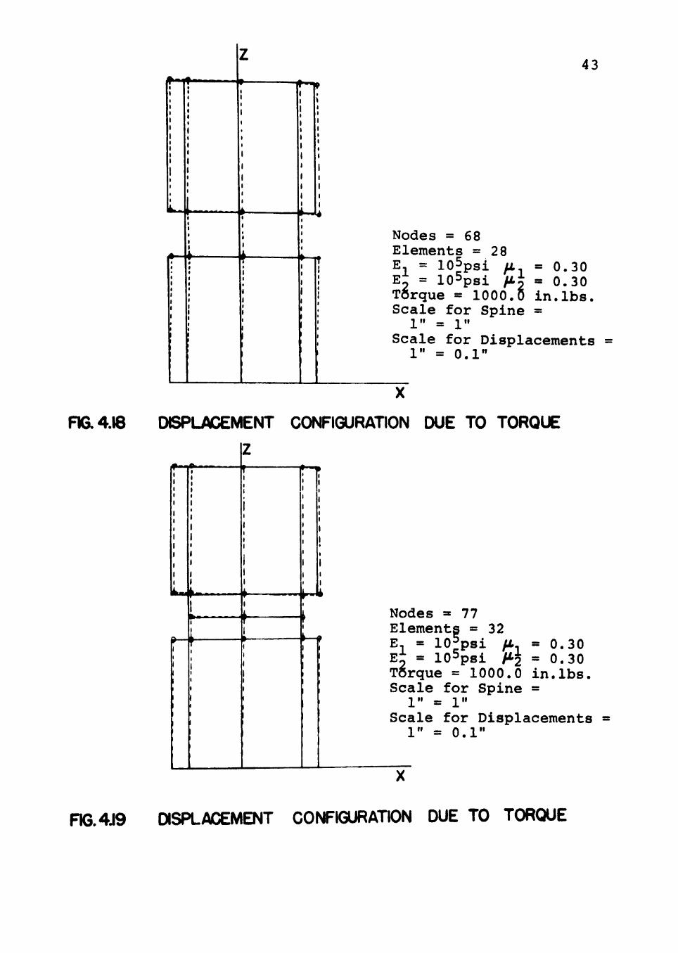
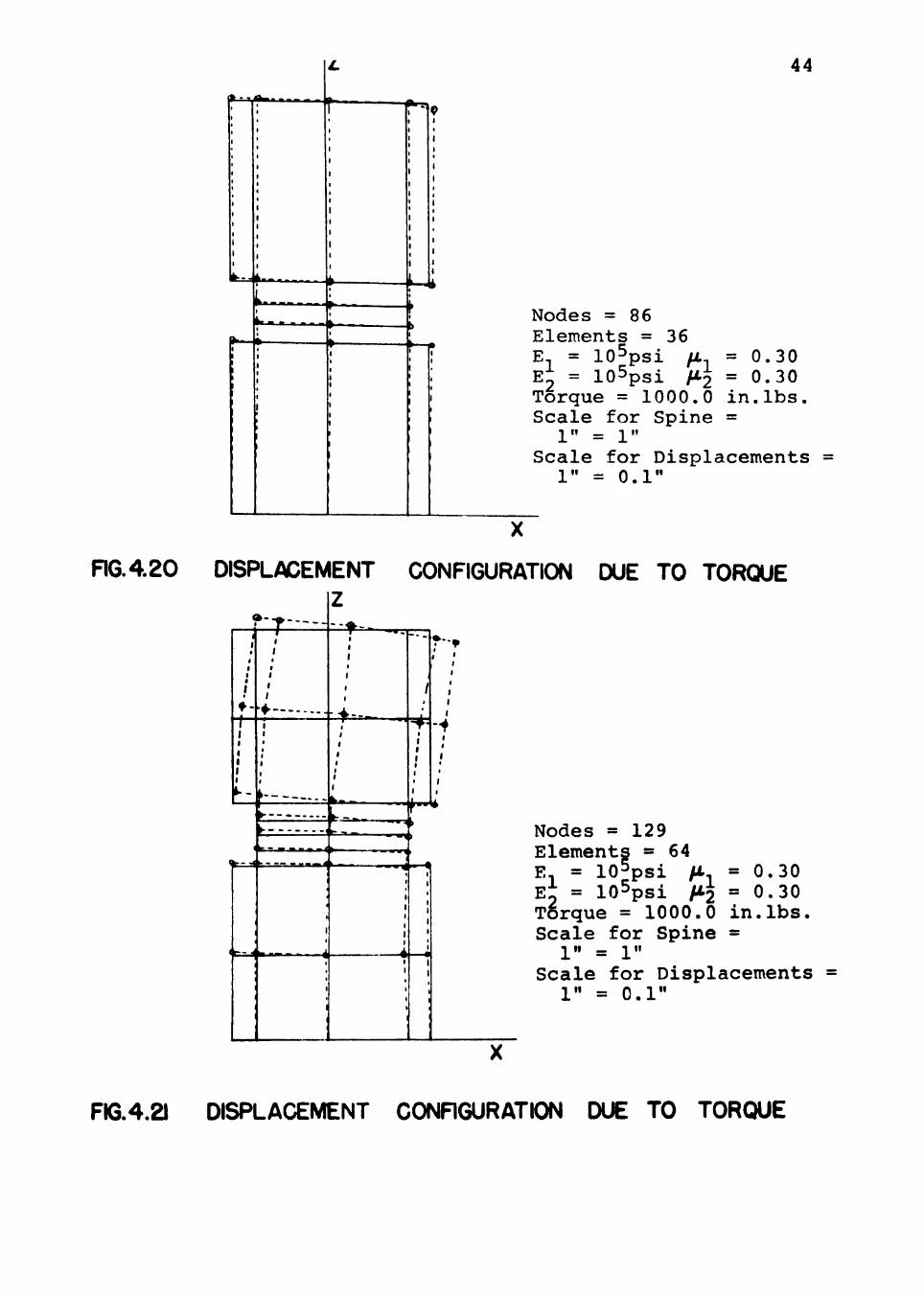
42
resulting displacement patterns are presented in Figs. 4.18,
.19, .20, .21 where the elastic constants of the vertebrae
and intervertebral disc are same as in previous analyses.
Then, the elastic constants of the vertebrae and the
intervertebral disc are varied so that they more closely
represent the real system properties. The deformation
characteristics of the system are shown in Figs. 4.22, .23,
.24, .25. It was noticed that the center of rotation was
found to move towards one side. This lateral movement is
similar to the misalignment behavior of the system under'
axial load. Since little is known about the actual con
nections between the vertebra and intervertebral disc,
perfect compatibility was assumed between the vertebra
and intervertebral disc in this finite element analysis.
As mentioned before, any lateral support from muscles and
other abdominal pressures is believed to resist this mis
alignment. This support was not considered in the analysis
presented herein.
From physical experiments, Farfan, et al (20) also
observed similar misalignment under torque loading condi
tions. However, it is not recommended at this point to
correlate the misalignment from the finite element
solution to that in the physical system.
In the finite element analysis, the six components
of stress at each nodal point are calculated from the
43
I *-JU
Nodes = 68 Elements = E E^ = iu-'p
28 T = lOSpsi fJL = 0 .30 2 = lOSpsi f t i = 0 .30
TOrque = 1000 .0 i n . l b s . S c a l e for Spine = 1" = 1"
Scale for Displacements 1" = 0.1"
FIG. 4.18 DISPLACEMENT CONFIGURATION DUE TO TORQUE
^ - 1 *
k « ^
h
i " * i%
M* Nodes = 77 Elements = 32 E = lOfps i ft- = 0 .30 E^ = l o S p s i H'2 = 0 .30 Torque = 1000 .0 i n . l b s . S c a l e for Spine =
1" = 1" Sca l e for Displacements
1" = 0 . 1 "
FIG.4J9 DISPLACEMENT CONFIGURATION DUE TO TORQUE
44
^ r
L t Nodes =86
Elements = 36 E, = 10= psi ft, = 0.30 E^ = 105psi fJ-T. = 0-30 Torque = 1000.0 in.lbs. Scale for Spine =
1" = 1" Scale for Displacements
1" = 0 . 1 "
FIG. 4 2 0 DISPLACEMENT CONFIGURATION DUE TO TORQUE Z
bt
::4—
k.^^
^ : : _ d >• • ! ? » • • » < k -^
Zmi ^
— » ^ l
—-^
I I
Nodes = 129 Elements = 64 E^ = lO^psi >t E2 = lO^psi M2 Torque = 1000.0 Scale for Spine =
1" = 1" Scale for Displacements =
1" = 0 . 1 "
= 0 .30 = 0 .30 i n . l b s .
FIG.4.21 DISPLACEMENT CONRGURATION DUE TO TORQUE

-9-
U^^
• • -
-4--4 Nodes =68 Elements =
= 105 28
Et = p S l fJL
•2 = 2200psi / t j
45
= 0.30 = 0.40 in.lbs. Torque = 1000.0
Scale for Spine = 1" = 1"
Scale for Displacements 1" = 0.1"
FIG. 4 2 2 DBPLACEMENT CONFIGURATION DUE TO TORQUE
^ ^ ^
^ - - « ^ - - -
?T:rrTT-
-If. ^ .
- ^ -~<k
-9
Nodes =77 Elements = 32 E, = lO^psi /i., = 0.30 E2 = 2200psi ^-2 = ^-^^ Torque = 1000.0 in.lbs. Scale for Spine = 1" = 1"
Scale for Displacements 1" = 0.1"
FIG. 4.23 DISPLACEMENT CONFIGURATION DUE TO TORQUE

1
1
1
1 1
1
1 1
^ - < i ^ - . . y
^ —
i 4
z
1
-• 1 1
- - ^ - - . . .-.4
f— 1
1 1
1 1
1
, 1
1 1
> 1
' 1 ,' 1
1 1
' 1
i ;
1 '
•:t-' • V SP"- 0
1
1
46
Nodes =86 Elements = 36
= lO^psi fi = 0.30 = 0.40 in.lbs.
E2 = 2200psi/i.2 Torque = 1000.0 Scale for Spine =
1" = 1" Scale for Displacements
1" = 0.1"
FIG.4.24 DISPLACEMENT CONFIGURATION DUE TO TORQUE
<»=^
i»
•7
^
.£5
i
^ ^ — — — <^
f"
I
I
I
I I
I
I
Nodes = 129 Elements = 64 E^ = lOSpsi fi = 0.30 E2 = 2200psi fi2 = 0.40 TOrque = 1000.0 in.lbs. Scale for Spine = 1" = 1"
Scale for Displacements 1" = 0.1"
RG.425 DISPLACEMENT CONFIGURATION DUE TO TORQUE
47
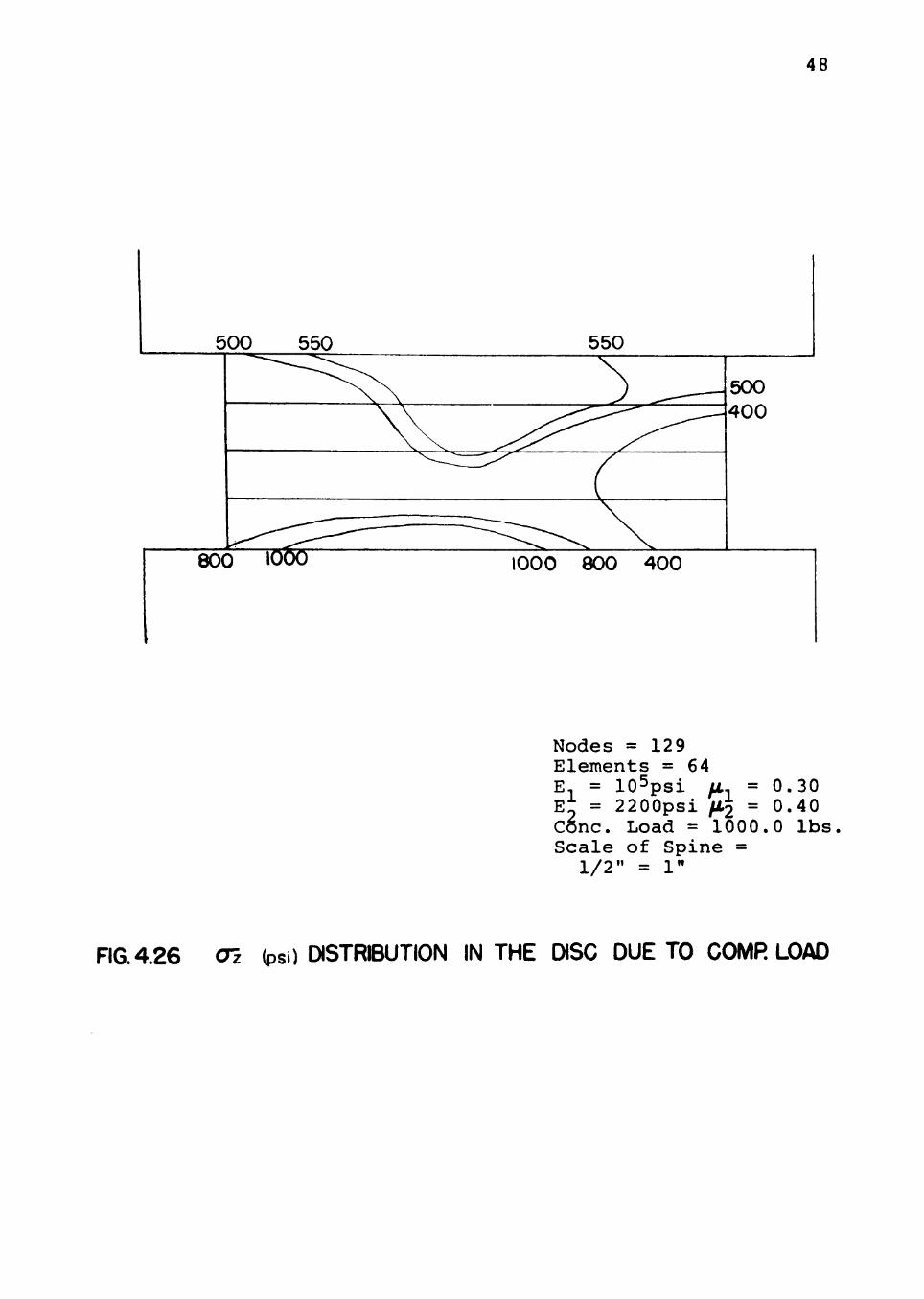
nodal displacements. Since the compressive stress is
supposed to cause greater damage to the disc than the
vertebra, only the distribution of compressive stresses
in the disc is shown in Figs. 4.26, .27, .28. However,
the stresses so computed were from the solutions where
some misalignment of the top vertebra was noticed.
Hence there can be inaccuracies in these stresses. Also,
due to lack of information in the present literature
regarding stresses and displacements in the actual lumbar
spine, it is very difficult to comment on the magnitudes
of stresses and displacements obtained from the.finite
element analysis.
48
500 550
80(
550
^ ^ " ^ ^ ^ ^ ^ -
\ \ ..^^^^^^^^^^^-^^^
^ ^ ~ ^ (
,^-"^1--'' 3 io6o
' ^^^ --C;; ^ 1000 800 400
500 400
Nodes = 129 Elements = 64
^1 = ^2 = Cone.
Scale 1/2
lO^psi 2200psi Load = 1000 of Spine =
" = 1 "
0. 0, .0
30 40 lbs
nG.4.26 Oz (psi) DISTRIBUTION IN THE DISC DUE TO COMR LOAD
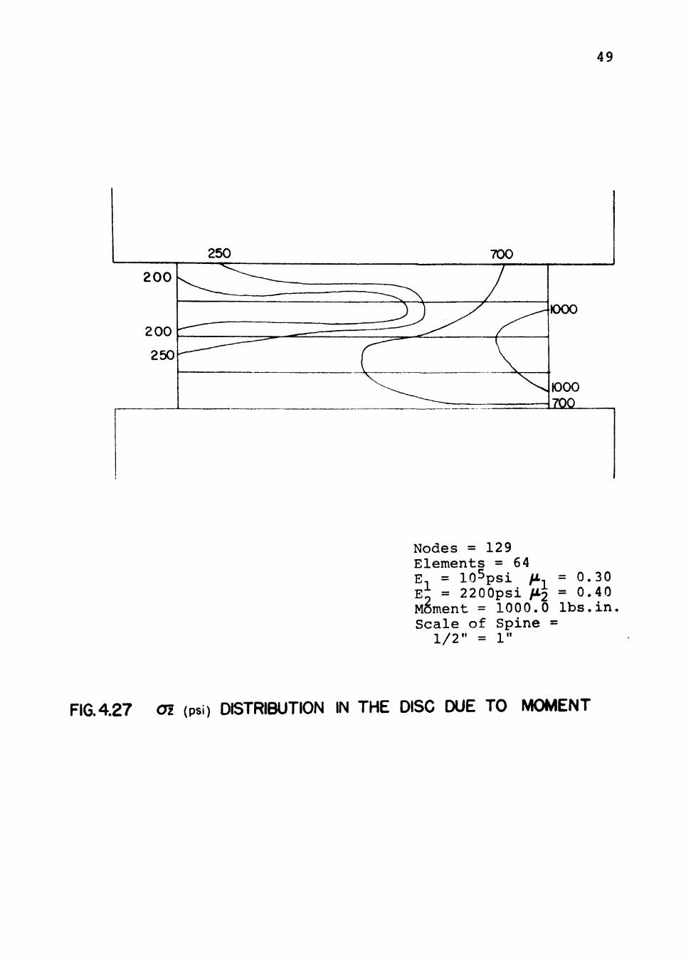
49
250 700
Nodes = 129 Elements = 64 E^ = lO^psi ft, = 0.30 E^ = 2200psi fl2 = 0.40 Moment = 1000.0 lbs.in Scale of Spine =
1/2" = 1"
R6.4.27 Oz (psi) DISTRIBUTION IN THE DISC DUE TO MOMENT

50
500_
750
a5a=
500
700
Nodes = 129 E lemen t s = 64 E, = l O ^ p s i /x, = 0 .30 E^ = 2200ps i /X2 = 0 .40 Torque = 1000.00 l b s . i n S c a l e of Sp ine =
1/2" = 1"
FIG. 4 2 8 Ol (psi) DISTRIBUTION IN THE DISC DUE TO TORQUE

CHAPTER V
SUMMARY, CONCLUSIONS AND RECOMMENDATIONS
FOR FURTHER STUDY
Summary
The lumbar spine system (fourth and fifth vertebrae
and intervertebral disc between them) is analyzed by the
finite element method. A tetrahedral finite element is
selected having three degrees of freedom for each node.
A stiffness matrix for the tetrahedral element is developed.
These element stiffness matrices are assembled to form
total stiffness matrix for the system (see Chapter III).
[K] {u> = »
where [K] is total stiffness matrix, <u> and <P> are the
corresponding displacement and force vectors. After
incorporating the boundary conditions, the displacement
vector is calculated from the above set of simultaneous
equations. Stresses are calculated from these corre
sponding displacements at each node. Arbitrary values of
1000 pounds axial load, 1000 in. pounds moment and 1000
in. pounds torque are applied in the analysis.
The effects of different mesh size and different
elastic constants for the vertebrae and the intervertebral
disc are also studied. 51
J^-.'JP*^
52
Displacement configurations (Figs. 4.2 to 4.25) are
drawn for different mesh size and keeping the material
properties same and different. Various loading conditions
are applied on the lumbar spine system such as axial com
pressive load, moment and torque. Stress distributions
in the disc for the above loading conditions are also
drawn (Figs. 4.25, .26, .27).
Conclusions
The following conclusions are drawn which are based
on the results of the investigation:
1. A misalignment behavior between the vertebra
is noticed when axial and torque loads are applied to the
system. It is concluded that this misalignment is due
to the instability in the simultaneous stiffness matrix
equations. Such an instability is observed when there is
a difference in the area of cross-section of the vertebra
and the disc, and when there is a large difference in
their material properties. Researchers (10, 20) have
noticed misalignment of the real lumbar spine system—
under axially symmetric loading conditions. They con
cluded from the physical observations that for an axially
loaded spine, the axial force is vectorially divided into
compressive and shearing components. The existence of a
forward shearing component created large shear strains
53
in the intervertebral disc. Farfan (20) noticed some
misalignment of the top vertebra when a torque was applied
at the top of the system.
2. Since for axially symmetric elastic problems,
the finite element solutions have to be axially sym
metric, the misalignment from the finite element solution
should not be equated to the misalignment of the real
system.
3. Tensile stresses occurred in the vertebra and
the intervertebral disc when a moment was applied at the
top. Ligaments, connecting the vertebra and the inter
vertebral disc are capable of resisting these tensile
stresses. However, the existence of ligaments were not
considered in this research.
4. The stresses shown here are for the arbitrarily
selected loads. When they are computed from the solutions
exhibiting misalignment, some inaccuracies should be
expected.
5. Due to the lack of information in the literature
regarding internal stresses and displacements within the
system, it is impossible to verify the displacements and
stresses obtained from the analysis.
Recommendations for Further Study
The following are the general recommendations for
the further study in this area:

54
1. The cause for the misalignments as observed in
axial/torque loading conditions should be fully investi
gated.
2. Since the elastic constants of the materials
represented in the spine model can have values within a
given range, representative value other than the average
should also be utilized in the analysis.
3. The spine should be analyzed for the combined
effect of loads such as axial compressive force, shear
force and moments.
4. Since the structural response of the spine is
highly non-linear even with low magnitudes of load, an
analysis technique should be developed which considers
both material and geometric non-linearities.
5. The investigation of the effects of vertebral
body sizes on the deformation of the system should be
considered.
6. The boundary conditions used in the present
investigation assumes complete fixity at the bottom of
the fifth lumbar vertebra. The effects of other feasible
boundary conditions should be investigated.
7. Further investigations should include other
supporting structures, such as ligaments and muscles,
occurring in the spine which are not included in this
simplified model.
55
8. Since the tetrahedral finite element used in
this analysis represents only constant strain components,
it is recommended to study the use of higher order finite
elements which may be more accurate.
REFERENCES
1. Peacock, Carlos. The Man and His Work. Greenwich, Conn., New York: Graphic Society, 1950.
2. Walmsley, John. A Man and His Work. Baltimore: Penguin Books, 1953.
3. Toundary, John. The Man and His Work. Greenwich, Conn., New York! Graphic Society, 1958.
4. Elward, J. F. "Motion in the Vertebral Column." American Journal of Roentgenology, XXXVI (1939), 91.
5. Lysell, E. "Motion in the Cervical Spine." Thesis. Acta orthopedic Scand. Supplement (1969), 123.
6. White, A. A. "Analysis of the Mechanics of the Thoracic Spine in Man." Thesis. Acta orthopedic Scand. Supplement (1969), 127.
7. Rolander, S. D. "Motion of the Lumbar Spine with Special Reference to Stabilizing Effect of Posterior Fusion." Thesis. Acta orthopedic Scand. Supplement (1966) , 90.
8. Morris, J. M.; Lucas, D. B.; and Bresler, M. S. "Role of Trunk in Stability of the Spirial." Journal of Bone and Joint Surgery XLIII(a) (1961), 327-351.
9. Chaffin, D. B. "Some Biomechanical Consideration in Manual Material Handling Task." Proceedings, 15th A., MTM Association, Ann Arbor, Michigan (January, 1967), 1-25.
10. Chaffin, D. B. "A Computerized Biomechanical Model-Development of and Use in Studying Gross Body Actions." American Society of Mechanical Engineering Paper No. 69-BMF-5, March, 1968.
11. Fisher, B. 0. "Analysis of Spinal Stresses During Lifting of a Biomechanic Model." M.S.I.E. Thesis. University of Michigan, Ann Arbor, Michigan, 1967.
56
57
12. Bradford, F. K., and Spurling, G. G. The Intervertebral Disc. Second Edition. Springfield, ill.: Charles C. Thomas, 1945.
13. Bartelink, D. L. "The Role of Abdominal Pressure in Relieving the Pressure of Lumbar Intervertebral ^^^^^•" Journal of Bone and Joint Surgery, XXXIX, No. 4 (November, 1957), 718-725. —
14. Floyd, W. F., and Silver, P. H. S. "The Function of the Erectores Spinac Muscles in Certain Movements and Postures in Man. Journal of Physiology, CXXIX (March, 1955), 184-203: ^
15. Theieme, F. P. "Lumbar Breakdown Caused by Erect Posture of Man." Anthropology Paper, University of Michigan (1950), 4, 5-6, 14-24, 37.
16. Spurling, R. G. Lesion of Lumbar Intervertebral Disc. Springfield, llTT: Charles C. Thomas, 1^53.
17. Chaffin, D. B. "A Computerized Biomechanical Model-Development of and Use in Studying Gross Body Actions." ASME Paper No. 69-BMF-5, March, 1968.
18. Evans, G. F., and Lissner, H. R. "Biomechanical Studies of the Lumbar Spine and Pelvis." Journal of Bone and Joint Surgery, XLI(a) (1959), 278-5^0.
19. Orne, David, and Liu, Y. King. "A Mathematical Model of Spinal Response to Impact." Journal of Biomechanics, IV (June, 1970) , 49-71.
20. Farfan, H. F.; Cossette, J. W.; Robertson, G. H.; Wells, R. v.; and Draus, H. "The Effect of Torsion on the Lumbar Intervertebral Joints: The Role of Torsion in the Production of Disc Degeneration." Journal of Bone and Joint Surgery, LII (April, 1970), 468-496.
21. Turner, M. J.; Clough, R. W.; Martin, H. C.; and Topp, L. J. "Stiffness and Deflection Analysis of Complex Structure." Journal of Aeronautical Sciences, XXIII (September, 1956), 805-823.
22. Clough, R. W. "Finite Element Method in Plane Stress Analysis," Proceedings, Second Conference on Electronic Computation, ASCE Structural Division, September, 1960, 345.
58
23. Hrennikoff, A. "Solution of Problem of Elasticity by the Frame Work Method." Journal of Applied Mechanics, ASME Trans., LXIII (December, 1941), A-169-A-175.
24. McHenry, D. "A Lattice Analogy for the Solution of Stress Problem." Journal of the Institution of Civil Engineers, XXl-XXli, No. 1 (Ue<56mb6r, 1943) , ir'aper No. b530, 59-82.
25. Mccormick, C. W. "Plane Stress Analysis." Journal ^£-^^^ Structural Division. Proceedings of ASCE Third Conference on Electronic Computation, Boulder, Colorado (June 19-21, 1963), Vol. 89, No. Sta. (August, 1963), Part 1.
26. Martin, H. C. "Plane Elasticity Problems and the Direct Stiffness Method." Trend in Engineering, University of Washington, Seattle, Vol. 13 (October, 1961).
27. Gallagher, R. H.; Padlog, J.; and Bijlard, P. P. "Stress Analysis of Heated Complex Shape." Journal of Aero-Space Science (November, 1962), 700-707.
28. Melosh, R. J. "Structure Analysis of Solids." Proceedings of ASCE, S.T.4, August, 1963, 205-223.
29. Cornell, D. C.; Jadhare, K. B.; and Rashid, Y. R. Safe 3-D—A Computer Program for the Three-dimensional Stress Analysis of Composite Structures. San Diego, California (September, 1967),
30. Vallabhan, C. V. Girija, and Reese, L. C. "Finite Element Method Applied to Problems in Soil Mechanics." Journal of the Soil Mechanics and Foundations Division, ASCE, Vol. 94, SM2 (March, 1968).
31. Vallabhan, C. V. Girija, and Mehta, Kishor C. "Stress-Strain Relationship from Compression Tests on Non-Linear Materials," Proceedings of the Symposium on the Use of Finite Element Method in Civil Engineering, Vanderbilt University, Nashville, Tennessee (Nov., 1969).
32. Crandall, S. H. Engineering Analysis. New York: McGraw-Hill Book Company, 1956.
33. Vallabhan, C. V. Girija. "Analysis of Shear Walls with Openings." Journal of the Structural Division, ASCE, Vol. 95, No. STIO (October, 1969).

Related Documents