CLINICAL SCIENCE Three-dimensional scanning with dual-source computed tomography in patients with acute skeletal trauma Duzgun Yildirim, I Cuneyt Tamam, II Terman Gumus III I Kasimpasa Military Hospital, Radiology Department, Turkey. II Kasimpasa Military Hospital, Orthopeadics and Traumatology Department, Turkey. III VKV American Hospital, Radiology Department, Turkey. OBJECTIVE: The aim of this study was to compare the efficiency of multiplanar reformatted images and three- dimensional images created after multidetector computed tomography examination in detecting acute post- traumatic osseous pathology of the skeletal system. METHOD: Between October 2006 and December 2008, 105 patients with a history of acute trauma were referred to our service. Patients were evaluated with multidetector computed tomography using multiplanary reconstructed images initially (R-I), and six months after this initial evaluation, three-dimensional images were assessed of each patient (R-II). Axial images were used for guiding as a reference Data obtained was recorded and graded according to importance levels of the pathologies. RESULTS: The R-II score was higher in the non-articular and highest in periartricular fractures of the extremities, and thoracic and pelvic cage injuries. For the spinal column, while R-I data was more significant In patients referred with polytrauma, R-II data, was more statistically significant, for short processing and adaptation time to acquiring immediate critical information. For all cases it was seen that three dimensional scans were more efficient in providing the orientation, within a short time. CONCLUSION: By dual source multidedector tomography systems trauma patients may be evaluated by multiplanary and three dimensionally reconstructed images. When used correctly, three dimensional imaging is advantageous and can help determine the exact nature and extension and also importance of osseous injuries. KEYWORDS: Multidetector computed tomography scan; Acute post-traumatic osseous pathology; Multiplanar reformatted images; Articular-periarticular osseous; Three-dimensional images. Yildirim D, Tamam C, Gumus T. Three-dimensional scanning with dual-source computed tomography in patients with acute skeletal trauma. Clinics. 2010;65(10):991-1002. Received for publication on May 25, 2010; First review completed on June 15, 2010; Accepted for publication on July 16, 2010 E-mail: [email protected] Tel.: 00905325998569 INTRODUCTION With recent developments in computerized tomography technology, multidetector computed tomography (MDCT) enabled better volume imaging and high-speed data acquisition, 1 allowing both increased coverage and improved resolution with less exposure to radiation, particularly in trauma patients. Parallel advances in image processing software and hardware warranted designing better examination protocols that optimize image quality for easy and quick interpreta- tion and minimize radiation dose. 2 The aim of this study was to compare the efficiency of multiplanar reformatted (MPR) images and three-dimensional (3D) images created after multidetector computed tomogra- phy (MDCT) examination in detecting acute post-traumatic osseous pathology of the skeletal system. We also set out to form a short guide to the use of 3D MDCT on trauma patients that would save this method from arbitrary application. MATERIALS AND METHOD Between October 2006 and December 2008, 105 consecu- tive patients (average age: 37, F = 30, M = 75) referred to our clinic with a history of acute trauma were retro- spectively evaluated. MDCT was performed on a 16- MDCT scanner (Somatom Definition, Siemens Medical Solutions, Germany). with tube voltage, 120-140 kV; effec- tive tube current, 240-280 mAs; section thickness 2 mm; reconstruction interval: 0.75 mm; and collimation 0.6 mm. During the scan, the automatic dose control system was activated to prevent excessive radiation exposure. Average scan time was between 11 and 23 seconds according to the different region of interest (ROI) settings. In Copyright ß 2010 CLINICS – This is an Open Access article distributed under the terms of the Creative Commons Attribution Non-Commercial License (http:// creativecommons.org/licenses/by-nc/3.0/) which permits unrestricted non- commercial use, distribution, and reproduction in any medium, provided the original work is properly cited. CLINICS 2010;65(10):991-1002 DOI:10.1590/S1807-59322010001000012 991

Welcome message from author
This document is posted to help you gain knowledge. Please leave a comment to let me know what you think about it! Share it to your friends and learn new things together.
Transcript
CLINICAL SCIENCE
Three-dimensional scanning with dual-sourcecomputed tomography in patients with acuteskeletal traumaDuzgun Yildirim,I Cuneyt Tamam,II Terman GumusIII
I Kasimpasa Military Hospital, Radiology Department, Turkey. II Kasimpasa Military Hospital, Orthopeadics and Traumatology Department, Turkey.III VKV American Hospital, Radiology Department, Turkey.
OBJECTIVE: The aim of this study was to compare the efficiency of multiplanar reformatted images and three-dimensional images created after multidetector computed tomography examination in detecting acute post-traumatic osseous pathology of the skeletal system.
METHOD: Between October 2006 and December 2008, 105 patients with a history of acute trauma were referred toour service. Patients were evaluated with multidetector computed tomography using multiplanary reconstructedimages initially (R-I), and six months after this initial evaluation, three-dimensional images were assessed of eachpatient (R-II). Axial images were used for guiding as a reference Data obtained was recorded and graded accordingto importance levels of the pathologies.
RESULTS: The R-II score was higher in the non-articular and highest in periartricular fractures of the extremities, andthoracic and pelvic cage injuries. For the spinal column, while R-I data was more significant In patients referred withpolytrauma, R-II data, was more statistically significant, for short processing and adaptation time to acquiringimmediate critical information. For all cases it was seen that three dimensional scans were more efficient inproviding the orientation, within a short time.
CONCLUSION: By dual source multidedector tomography systems trauma patients may be evaluated by multiplanaryand three dimensionally reconstructed images. When used correctly, three dimensional imaging is advantageousand can help determine the exact nature and extension and also importance of osseous injuries.
KEYWORDS: Multidetector computed tomography scan; Acute post-traumatic osseous pathology; Multiplanarreformatted images; Articular-periarticular osseous; Three-dimensional images.
Yildirim D, Tamam C, Gumus T. Three-dimensional scanning with dual-source computed tomography in patients with acute skeletal trauma. Clinics.2010;65(10):991-1002.
Received for publication on May 25, 2010; First review completed on June 15, 2010; Accepted for publication on July 16, 2010
E-mail: [email protected]
Tel.: 00905325998569
INTRODUCTION
With recent developments in computerized tomographytechnology, multidetector computed tomography (MDCT)enabled better volume imaging and high-speed dataacquisition,1 allowing both increased coverage and improvedresolution with less exposure to radiation, particularly intrauma patients.
Parallel advances in image processing software andhardware warranted designing better examination protocolsthat optimize image quality for easy and quick interpreta-tion and minimize radiation dose.2
The aim of this study was to compare the efficiency ofmultiplanar reformatted (MPR) images and three-dimensional
(3D) images created after multidetector computed tomogra-phy (MDCT) examination in detecting acute post-traumaticosseous pathology of the skeletal system. We also set out toform a short guide to the use of 3D MDCT on trauma patientsthat would save this method from arbitrary application.
MATERIALS AND METHOD
Between October 2006 and December 2008, 105 consecu-tive patients (average age: 37, F = 30, M = 75) referred toour clinic with a history of acute trauma were retro-spectively evaluated. MDCT was performed on a 16-MDCT scanner (Somatom Definition, Siemens MedicalSolutions, Germany). with tube voltage, 120-140 kV; effec-tive tube current, 240-280 mAs; section thickness 2 mm;reconstruction interval: 0.75 mm; and collimation 0.6 mm.During the scan, the automatic dose control system wasactivated to prevent excessive radiation exposure.
Average scan time was between 11 and 23 secondsaccording to the different region of interest (ROI) settings. In
Copyright � 2010 CLINICS – This is an Open Access article distributed underthe terms of the Creative Commons Attribution Non-Commercial License (http://creativecommons.org/licenses/by-nc/3.0/) which permits unrestricted non-commercial use, distribution, and reproduction in any medium, provided theoriginal work is properly cited.
CLINICS 2010;65(10):991-1002 DOI:10.1590/S1807-59322010001000012
991
Table 1 - Patients and regions affected by trauma and injury: scores of findings.
Score of findings
No Age sex Affected Area Mechanism Dominant Pathology R-I R-II
1 20 m Maksillofacial GSW Orbital foreign body 1 2
2 22 m Pelvis TA Iliac wing fracture 1 2
3 47 m Spinal Column TA C-2 pedicle fracture 2 1
4 7 f Maksillofacial TA Blow-out fracture 3 1
5 27 m Extremity articular TA Knee avulsion fracture 2 1
6 19 f Extremity articular TA Tibia plato fracture 1 2
7 60 m Maksillofacial TA Maksillofacial fracture 1 2
8 15 m Extremity Sport trauma Malunion + fissure 2 1
9 20 m Maksillofacial TA Tibia medial MF kondil fracture 1 2
10 24 m Extremity GSW Extremity comminuted fracture (CT-A) 1 2
11 20 m Extremity TA Tibial stress fracture 2 1
12 31 m Pelvis TA Acetabulary fracture 1 2
13 20 m Pelvis TA Asymmetric sacralization (variative) 1 2
14 58 f Maksillofacial TA Multiple fractures 1 2
15 20 m Maksillofacial TA Traumatic strabismus 1 1
16 59 f Extremity TA Impacted humeral fracture 1 3
17 26 m Maksillofacial Beating Zygomal fracture 1 2
18 22 m Maksillofacial Beating Zygomal fracture 1 2
19 30 m Extremity articular TA Shoulder comminuted fracture 1 3
20 59 m Extremity articular TA Shoulder comminuted fracture 1 2
21 52 f Spinal Column Fall Coccygeal fracture 2 1
22 25 m Extremity Fall Coracoid fracture 1 2
23 78 m Maksillofacial TA Mandibular pseudofracture 1 3
24 43 m Extremity TA Comminuted fracture 1 3
25 30 f Maksillofacial TA Maksillofacial fracture 1 2
26 30 f Maksillofacial Beating Nasal bone fracture 1 2
27 7 f Maksillofacial TA Orbital rim fracture 3 1
28 32 f Maksillofacial TA Orbital rim fracture 1 2
29 21 m Maksillofacial TA Orbital rim fracture 1 2
30 28 m Maksillofacial TA Multiple fractures 1 2
31 20 m Maksillofacial TA Multiple fractures 1 1
32 26 m Extremity articular Fall Elbow fracture 1 2
33 22 m Maksillofacial TA Temporal bone fracture 1 1
34 60 m Maksillofacial TA Multiple fractures 1 2
35 21 m Maksillofacial TA Orbital rim fracture 3 2
36 21 m Maksillofacial TA Multiple fractures 1 3
37 25 m Extremity TA Tibial fracture 1 2
38 26 m Spinal Column TA Vertebral anomaly 1 2
39 20 m Extremity articular Fall Osseous Bankart’s lesion 1 3
40 11 f Extremity articular Fall Salter-Harris type-IV epyphyseal lesion 1 2
41 29 m Maksillofacial Fall Calvarial fracture 1 2
42 70 m Extremity TA Humeral fracture 1 2
43 83 f Maksillofacial Beating Scalp hematoma 1 1
44 20 m Maksillofacial TA Basicranial multiple fractures 1 1
45 41 m Maksillofacial Beating Scalp defect 1 2
46 52 f Extremity TA Scapular fracture 1 1
47 93 f Extremity Fall Femoral neck impacted fracture 3 0
48 43 m Extremity TA Humeral fracture 1 2
49 32 f Maksillofacial Beating TMJ condyle dislocated fracture 1 2
50 42 m Extremity articular Fall Radius distal head fracture 1 2
51 22 m Maksillofacial TA Maksillofacial multiple fracture 1 2
52 52 m Extremity Fall Internal fixation device fracture 1 2
53 43 f Spinal Column Fall Vertebral fixation device displacement 1 2
54 87 f Extremity Fall Severe osteophytic exostosis 1 2
55 20 m Spinal Column TA Dens fracture 1 1
56 1 f Maksillofacial Fall Calvarial fracture 1 3
57 21 f Extremity Fall Humeral fracture 1 2
58 21 m Extremity articular Fall Elbow fracture 1 2
59 21 m Politrauma TA Multiple fractures 1 2
60 23 f Spinal Column TA Cervical vertebrae fracture 2 2
61 28 m Extremity articular TA Calcaneal fracture 1 3
62 32 m Maksillofacial TA Nasal bone and soft tissue injury 1 2
63 37 m Extremity articular TA Shoulder comminuted fracture 1 2
64 37 m Extremity Fall Os vesalineum-accesory bone 1 2
65 38 m Extremity articular TA Shoulder comminuted fracture 1 2
66 21 m Extremity articular Fall New fracture at the operated Bankart’s lesion 1 2
67 24 m Extremity GSW Multiple fractures, CT angiography 1 3
68 27 m Pelvis TA Avulsion of the pelvic rim 1 3
69 27 m Extremity articular TA Shoulder & ankle fractures 1 2
Three-dimensional scanning in patients with acute skeletal traumaYildirim D et al.
CLINICS 2010;65(10):991-1002
992
3 cases, 1 with a suspicion of pathological fracture after thefirst examination, and 2 with identified vascular injury, anintravenous non-ionic contrast agent (iohexol 1-1.2 ml/kg)was used. All the other examinations were completedwithout administration of contrast. Scans with contrastwere applied in emergency settings, no bolus trackingmethod was applied, and scans were obtained in the arterialphase with 25-30 sec as delay time.
After axial scanning, thin section reconstructions werealso generated by reconstruction in both soft tissue (B10-softtissue) and bony kernels (B 70-sharp osteo). In bothconvolution kernels, single data with a slice thickness of2 mm (1.5 mm reconstruction increment) were used to formthe reconstructed images. These reconstructed thin sectionimages were transferred to a special workstation (LeonardoRunning Inpace, Siemens Medical Solutions) and then
Score of findings
No Age sex Affected Area Mechanism Dominant Pathology R-I R-II
70 28 f Extremity articular TA Shoulder 1 2
71 29 f Maksillofacial Fall Lip soft tissue incisioun 1 3
72 29 m Extremity articular TA Ankle communited fracture 1 1
73 29 m Extremity TA Multiple open fracture 1 3
74 33 f Spinal Column TA Cervical vertebra fracture 2 2
75 37 m Rib(s) TA Thoracic deformity 1 3
76 40 m Extremity Fall Radius fracture 1 3
77 41 m Maksillofacial TA Occipital condyle fracture 1 2
78 47 m Extremity articular Fall Scapulary dislocation 1 3
79 55 m Rib(s) TA Costal fractures 1 3
80 62 m Extremity Fall Open tibial fracture 1 3
81 80 f Spinal Column Fall Generalized Spinal Column spurs 1 3
82 68 m Maksillofacial Beating Forehead incision 1 3
83 69 m Maksillofacial TA Orbital fracture 1 2
84 72 m Maksillofacial Fall Soft tissue injury 1 2
85 83 m Extremity articular TA Shoulder comminuted fracture 1 2
86 22 m Maksillofacial TA Multiple fractures 3 2
87 69 f Spinal Column TA Spinal Column fixation device displacement 3 1
88 58 f Maksillofacial TA Comminuted facial bone fractures (CT-A) 1 2
89 28 m Rib(s) TA Costal fractures 1 3
90 4 m Spinal Column Fall Atlanto-occipital fusion anomaly 1 2
91 52 m Extremity Fall Enthesopathic ossification 1 3
92 4 f Maksillofacial Fall Trauma and previous cranioectomy 1 2
93 72 f Extremity Fall Femoral neck fracture 3 0
94 28 m Extremity articular TA Elbow intrarticular fracture 2 2
95 74 m Extremity articular Fall Patellar avulsion fracture 2 2
96 26 m Politrauma TA Multiple fractures 1 3
97 22 m Extremity articular Sport trauma Metatars fractures 1 3
98 54 f Maksillofacial TA Lytic lesions 1 2
99 34 m Maksillofacial TA Frontal calvarial fracture 1 1
100 34 m Pelvis TA Acetabulary roof fracture 1 2
101 28 m Spinal Column TA Sternal fracture 3 0
102 37 f Rib(s) Fall Multiple rib fractures 0 2
103 44 m Extremity articular TA Femoral head displaced fracture 1 2
104 39 f Extremity articular Fall Radiocarpal dislocation 1 2
105 11 m Extremity Fall Fibulary epiphyseal fracture 1 2
Maxillofacial: 38
Pelvis: 5
Extremity articular: 16
Spinal Column 11
Extremity 22
Politrauma: 2
Rib 4
Table 1 - Continued.
Table 2 - Importance level of the findings for defining the osseous injury score.
Unimportant N Incidental variants, congenital deformities
N Nonulcerated soft tissue changes, additional stabile rib fractures, non-complicated simple fractures defined only by physical
examination
N Noncomplicated fractures and foreign bodies remote from the vital organs or areas
Important N Noncomplicated fractures and foreign bodies adjacent to the vital organs or areas
N Complicated fractures, instable fractures
N Trauma cases with fractures around or through the metallic implants
N Pathologic fractures
N Life-threatening multiple fractures
N Unstable thorasic cage, maksillofacial (orbital rim blow-out), sternal displaced fractures.
N Intraarticular fractures
CLINICS 2010;65(10):991-1002 Three-dimensional scanning in patients with acute skeletal traumaYildirim D et al.
993
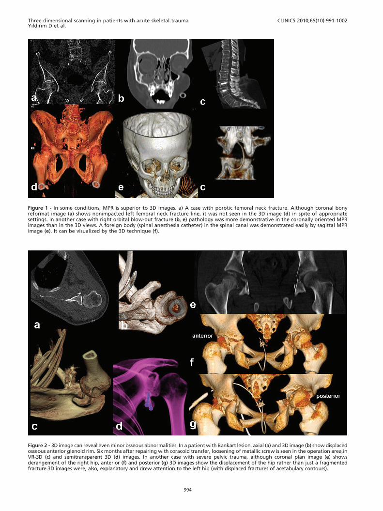
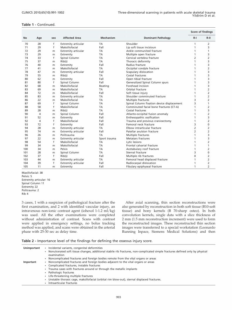
Figure 1 - In some conditions, MPR is superior to 3D images. a) A case with porotic femoral neck fracture. Although coronal bonyreformat image (a) shows nonimpacted left femoral neck fracture line, it was not seen in the 3D image (d) in spite of appropriatesettings. In another case with right orbital blow-out fracture (b, e) pathology was more demonstrative in the coronally oriented MPRimages than in the 3D views. A foreign body (spinal anesthesia catheter) in the spinal canal was demonstrated easily by sagittal MPRimage (e). It can be visualized by the 3D technique (f).
Figure 2 - 3D image can reveal even minor osseous abnormalities. In a patient with Bankart lesion, axial (a) and 3D image (b) show displacedosseous anterior glenoid rim. Six months after repairing with coracoid transfer, loosening of metallic screw is seen in the operation area,inVR-3D (c) and semitransparent 3D (d) images. In another case with severe pelvic trauma, although coronal plan image (e) showsderangement of the right hip, anterior (f) and posterior (g) 3D images show the displacement of the hip rather than just a fragmentedfracture.3D images were, also, explanatory and drew attention to the left hip (with displaced fractures of acetabulary contours).
Three-dimensional scanning in patients with acute skeletal traumaYildirim D et al.
CLINICS 2010;65(10):991-1002
994
multiplanar reformat (MPR), maximum intensity projection(MIP) and 3D images were generated.
Assessments were performed by a radiologist on sophis-ticated multidisplay screens. Axial and MPR images wereevaluated immediately after each shot, and data wererecorded as record I (R-I).Six months after the initialassessment of each patient, only the axial and 3D images
were regenerated and evaluated again by the same radiolo-gist. The data obtained were recorded as record II (R-II).
During R-I evaluation, MPR images were examined incoronal, sagittal and if needed in curved or oblique planes.In R-II evaluation, 3D images were examined by rotating theimage fully around the coronal and horizontal axis (ifneeded in oblique positions) at least once. 3D images were
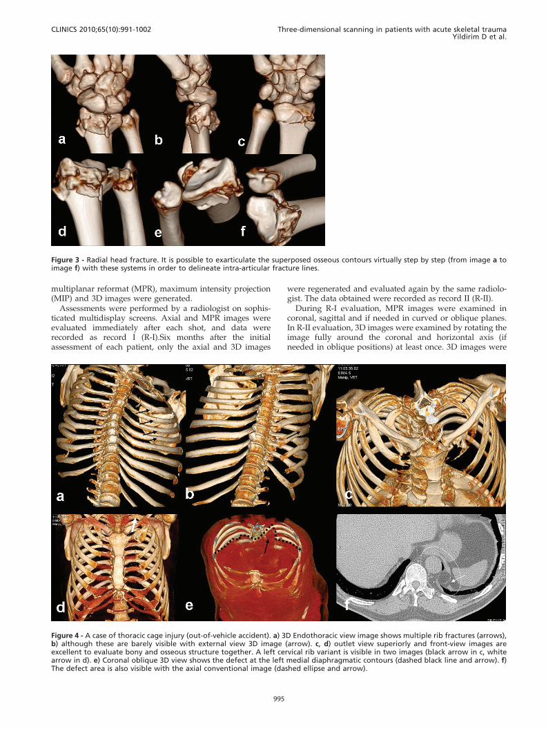
Figure 3 - Radial head fracture. It is possible to exarticulate the superposed osseous contours virtually step by step (from image a toimage f) with these systems in order to delineate intra-articular fracture lines.
Figure 4 - A case of thoracic cage injury (out-of-vehicle accident). a) 3D Endothoracic view image shows multiple rib fractures (arrows),b) although these are barely visible with external view 3D image (arrow). c, d) outlet view superiorly and front-view images areexcellent to evaluate bony and osseous structure together. A left cervical rib variant is visible in two images (black arrow in c, whitearrow in d). e) Coronal oblique 3D view shows the defect at the left medial diaphragmatic contours (dashed black line and arrow). f)The defect area is also visible with the axial conventional image (dashed ellipse and arrow).
CLINICS 2010;65(10):991-1002 Three-dimensional scanning in patients with acute skeletal traumaYildirim D et al.
995
first produced from the skin surface to the soft tissues, andthen to the bony structure surface by changing the windowsettings. Both the volume rendered (VR) and surface shadeddisplay (SSD) methods were used for 3D imaging. If needed,virtual extraction of foreign materials superposed to theregion of interest was used. It was also possible to evaluatejoint surface congruity with virtual exarticulation to removesuperposed structures during some R-II evaluation.
All data obtained from both evaluations were summar-ized in a detailed table (Table I). Osseous pathologiesdetermined by the R-I and R-II were scored by means of aspecial grading system. In this system, coordination was setup with the clinician who referred the cases to our serviceand the data collected were categorized as important orunimportant. The data classified as important were essentialfor diagnosis and might potentially change the approach tothe treatment. Minor findings that did not affect thetreatment algorithm were classified as unimportant cate-gory (Table 2). Data obtained in both evaluations werescored according to their importance. Under this scheme,when no major pathology could be determined (between R-Iand R-II) a value of ‘‘0’’ was assigned; when an abnormalitywas both detected and described, the value assigned was‘‘1’’; when unimportant data were determined the othermode; the value was ‘‘2’’; and if a different finding in theimportant category was reported, the value was ‘‘3’’.
The average score (OIS: Osseous Injury Score) wascalculated and the statistical difference between the pointsof the two methods was measured with the Chi-square test.
The patients were informed before the examinations, andconsent was obtained. Neural parenchymal injuries, med-iastinal or pulmonary parenchymal injuries and thoracoab-dominal solid/luminal organ injuries, effusions orcollections or other soft tissue injuries were reported withboth evaluations (R-I and R-II) but in accordance with theaim of the study, only osseous findings were reflected to thestatistical analyses.
RESULTS
Most of the cases had suffered traffic accidents (out-of-vehicle traffic accident = OVTA, n = 34; in-vehicle trafficaccident = IVTA, n = 29), The remaining cases were gunshotwounds (GSW, n = 3), falling accidents at work (Fall, n = 30),sports-related injuries (Sport trauma, n = 2), and assault(Beating, n = 7).
Extremity+joint injuries (n = 42) and maxillofacial injuries(n = 38) were mostly seen, the osseous spinal axis wasscanned in 10 subjects, the thoracic cage in 3 subjects, thepelvic cage in 5 subjects, and the whole body in 7polytraumatic subjects.
The total time needed for the evaluation of the osseouspathologies of the 105 cases was calculated as approxi-mately 1600 minutes for R-I, and 1200 minutes for R-II.
In agreement with the principles stated in Table 1; in 8cases unimportant findings, and in 6 cases importantfindings, were noted by R-I as distinct from the othermethod. On the other hand, R-II examination of the 3D
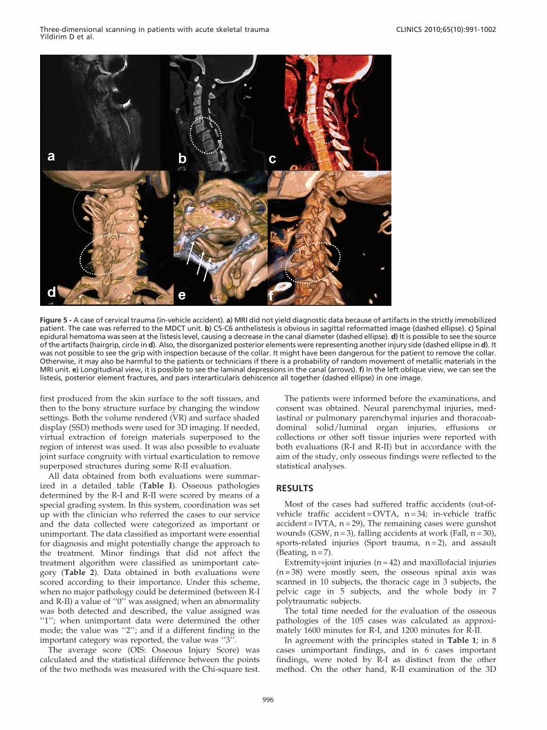
Figure 5 - A case of cervical trauma (in-vehicle accident). a) MRI did not yield diagnostic data because of artifacts in the strictly immobilizedpatient. The case was referred to the MDCT unit. b) C5-C6 anthelistesis is obvious in sagittal reformatted image (dashed ellipse). c) Spinalepidural hematoma was seen at the listesis level, causing a decrease in the canal diameter (dashed ellipse). d) It is possible to see the sourceof the artifacts (hairgrip, circle in d). Also, the disorganized posterior elements were representing another injury side (dashed ellipse in d). Itwas not possible to see the grip with inspection because of the collar. It might have been dangerous for the patient to remove the collar.Otherwise, it may also be harmful to the patients or technicians if there is a probability of random movement of metallic materials in theMRI unit. e) Longitudinal view, it is possible to see the laminal depressions in the canal (arrows). f) In the left oblique view, we can see thelistesis, posterior element fractures, and pars interarticularis dehiscence all together (dashed ellipse) in one image.
Three-dimensional scanning in patients with acute skeletal traumaYildirim D et al.
CLINICS 2010;65(10):991-1002
996

scans recorded important findings in 23 patients andunimportant findings in 52.
Data recorded by using two methods in the other 11 caseswere scored at the same level.
In 7 patients (one case with non-displaced femoral neckfracture, one case with a minimal impacted femoral neckfracture, 4 cases with orbital blow-out and/or rim fracturesand a case with a foreign body in the spinal canal) wererecorded as ‘‘2 or 3 points’’ in R-I, while R-II scores were ‘‘0or 1 points’’ (Figure 1).
Otherwise, the differences recorded as important in R-IIwere related to 8 cases with upper extremity injuries, 9 caseswith lower extremity injuries, and 5 cases with thoraciccage/pelvic cage/spinal injuries (Figure 2).
The R-II score was higher in the non-articular fractures ofthe extremities, with an average score of 2 points. On theother hand, in the articular-periarticular osseous injuries, R-II were assigned 3 points on average by more orientedimages (Figure 3).
While the R-II data were determined to be in the moreimportant category for the thoracic cage (at the 3 pointslevel), more data were provided compared to R-I (unim-portant category-weighted) with a 2 point average for thepelvic cage (Figure 4).
For the spinal column, R-I data were more significant,with 2 points in the definition of the anterior compartmentconfiguration (listhesia, compression fracture detection andorientation to fracture configuration). Also, for intracanali-cular pathologies (posterior elements or fragmentous dis-placements to the canalicular surface, foreign bodies and -despite not being included in the statistical evaluations -epidural soft tissue components) R-I was scored with3 points compared the ‘‘1 or 2’’ points scores of R-II.However, R-II data were again more significant in the injuryor extracanalicular displacement of the posterior elements ofthe osseous spinal column (Figure 5, Figure 6).
Also, in another two patients referred with polytrauma,R-II data, which were found to be more statisticallysignificant, were scored with 3 points higher on averagethan R-I in the aspects of orientation, short processing and
Figure 7 - Right cruris injury in a vehicle accident,. a) The open and wide wound at the trauma site is visible. b) In the 3D CT-A image,the popliteal artery was interrupted suddenly because of penetrating vascular trauma. c) After removal of the bony structure, it wasseen that the collateral supply (a variation) from the genicular branch was enabling the distal tissue to survive.
Figure 6 - Cranial trauma. a) Cerebral herniation from the defectin the left parietal area. b) All drainage tubes, catheters and thedefect area can be seen in different 3D Windows (b, c). In thesame patient it was also detected the abdominal catheters(drainage tubes, gastrostomy tube, d) and buried calvarium inthe abdominal wall (e).
CLINICS 2010;65(10):991-1002 Three-dimensional scanning in patients with acute skeletal traumaYildirim D et al.
997
adaptation time (5 mins versus 11 mins) for acquiringcritical information (Figure 6, Figure 7).
The measured average score for R-I for all of the subjectswas 1.25; while it was recorded as 1.99 for R-II. Thus, astatistically significant difference (p = 0.000005) was shownin the Chi-square test, which proved that findings describedby the R-II method defined posttraumatic pathologies moreefficiently. In the all evaluated data, it was seen that 3Dscans were fast and more efficient in providing goodorientation for clinicians.
DISCUSSION
To our knowledge, this is the first article about thestandardization of postprocessing operations in the litera-ture in English. With this study, our aim was to display theusefulness and differences of both (MPR versus 3-D)modalities, with their advantages and disadvantages. Inthis way, we intended to make a first step towards the
standardization of the postprocessing algorithm, at least forosseous trauma patients.
MDCT plays a major role in diagnostic workflow in theevaluation of patients with trauma.3,4
Traumatized patients usually have injuries in severalanatomical regions or organs, and CT assessment of suchpatients should be systematic, complete, and accurate.Another key factor is the time required for radiologicalexamination, which, because the chance of survivalincreases the sooner trauma care is initiated, must be asshort as possible.3,5
The reliability and workflow of MDCT for emergencypurposes have been supported by the results of severalstudies.5-9 MDCT scanners are widely used because theyrapidly produce high-resolution images of large areas,offering short examination times for multiple body regionsunder emergency conditions.6-11 With new software pro-grams and systems which have 64 or more detectors, 3Dscanning and also processing time has been reduced
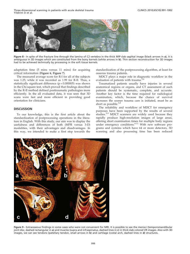
Figure 8 - In spite of the fracture line through the lamina of C2 vertebra in the thick MIP slab sagittal image (black arrows in a), it isambiguous in 3D images which are constituted from the bony kernels (white arrows in b). Thin section reconstruction for 3D imageshad to be achieved technically by processing in the soft tissue kernels.
Figure 9 - Extraosseous findings in some cases who were not convenient for MRI. It is possible to see the menisci (temporomandibularjoint disc, dashed rectangular in a) and muscles (supra and infraspinatus, dashed lines in c) in thick slab colored VR images. Also with 3Dimages, we can see tendons (patellary tendon, small arrows in b) and cartilage (costal arch, dashed lines in d) structures.
Three-dimensional scanning in patients with acute skeletal traumaYildirim D et al.
CLINICS 2010;65(10):991-1002
998
significantly.4 Additionally, reduced radiation exposurerates have made the MDCT as preferred method in thetrauma setting especially in unstable and uncooperativecases. Sometimes, it is possible to examine the affected area
can be completed in subsecond time with new generationmachines. So, it can exclude any requirement for sedationwhich may be used as a first line examination methodespecially in pediatric trauma cases.5,12 Seven pediatriccases in this study had been diagnosed directly with MDCTexamination but without need for MRI or direct radio-graphy correlation.
Orientation can be facilitated with MPR and 3D recon-struction in addition to the conventional axial imageswithout changing routine MDCT examination protocolsfor trauma. Although there are many studies about the CTor MDCT protocols in trauma cases; there is no other recordwhich emphasizes the standardization of the postprocessingalgorithm or efficiency of 3-D images objectively.3,9,11 In thisstudy, while high resolution axial plus MPR images may beenough, we answer the question as to whether or not theformation and evaluation of the 3D images is needed.
It is also a known fact that besides the difficulty of quickevaluation of a high number of axial images consecutively,there are also difficulties regarding time and cost in thestorage and retrieval of this information when needed.13
Forming and storing 3D images may partially alleviate thisproblem. Likewise, another important but overlooked pointis the opportunity for processing the same data to produce3D images from remote computers. This makes virtualinspection by teleradiologists possible. Although transfer-ring high resolution and numerous images consumes time, asmall number of focused 3D images can be transferred in ashort time.14,15
It must be remembered that images reconstructed in thebone window give higher contour resolution in the sectionalimages, whereas thin axial images reconstructed in softtissue kernels should be used for 3D evaluation16 (Figure 8).
The average time needed for each case for R-I and R-IIprotocols was 15 minutes, and 11,5 minutes respectively. Atemergency setting, the time spared with R-II protocol iscritical for each patient. One of the facilities in the
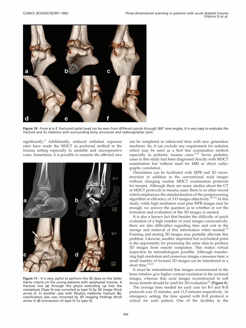
Figure 10 - From a to f, fractured radial head can be seen from different points through 360˚ view angles. It is very easy to evaluate thefracture and its relations with surrounding bony structures and radiocapitallar joint.
Figure 11 - It is very useful to perform the 3D data on the SalterHarris criteria on the young patients with epiphyseal trauma. Afracture line (a) through the physis extending up into themetaphysis (Type II) was corrected as type IV by 3D image (thickarrow c). In another case with fibulary malleolar fracture (b),classification also was corrected by 3D imaging findings (thickarrow in d) (conversion of type IV to type II).
CLINICS 2010;65(10):991-1002 Three-dimensional scanning in patients with acute skeletal traumaYildirim D et al.
999
evaluation of 3D images is the ability to orient the reader’sattention directly to the injury site by turning around theskeleton to reveal any defect 16,23 (Figure 14). In this way, itis possible to detect abnormalities easily in a short time.24,25
It is also is possible to reduce the artifacts or and to removesuperposition (missed foreign bodies, pathological frac-tures, superposed implants or catheters) by this method.
With R-I protocol eight extra unimportant findings wereidentified where as in R-II protocol 52 additional unim-portant findings was found. In terms of important findings,R-I noted 6 and R-II recorded 23 important findings. In only11 cases, both methods scored the same important findings.
R-I protocol was thought to be the appropriate protocolfor the evalaution of basicranium, orbital rim (blow-out),temporal bone, spinal canal, vertebral body internal contourinjuries and intra-articular fragments due to their complexanatomical structures and superpozitions. R-II protocol wasused to evaluate facial bones, calvarium, ribs, the posteriorelements of the spinal column, long bones and articularsurface integrity because it provided quick and cumulativeinformation. It is obvious that usage of improper modalityin inappropriate conditions leads time consumption
In some conditions, one of these techniques may bemandatory due to different characteristics of patients. Forexample, non-displaced but minimally impacted poroticfemoral neck fractures can only be identified by the evaluationof axial+3D images. In porotic patients, 3D images, even withsuitable reconstruction, were not able to show the pathologieslike fissures or nondisplaced fracture lines.
In this study, 3D images were examined by turning imagefully around the vertical and horizontal axis (if needed inoblique positions) at least once. 3D image windows wereproduced from skin surface to the soft tissues at first, andthen to the bony structure examined in more suitable colors.
Because of the scope of the study, we emphasized theefficiency of the 3D images in the acute post-traumaticosseous changes. However, superficial anatomy, tendons,periarticular ligaments, muscles and meniscal structures canbe seen clearly with the colored 3D-VR images withoutadministering any contrast agent.17,18 Thus, this method willbe crucial in cases where MRI examination is contradicted10
(Figure 9).Patients with huge defects in their skin or other soft
tissues but without any osseous injury being reported asnormal with conventional axial or MPR images because ofobscurence in sectional slices. But this may lower theconfidence of readers. However, those injuries can bedetermined easily by 3D application examination. Withthe pointing out of the primary injuried sites, 3D applicationis an interesting tool which can be equal to diffusionweighted imaging considering that it has an effect thataccelerates diagnosis.
In our cases, MPR images presented more useful dataespecially in spinal column injuries, and in intracanalicularpathologies (posterior vertebral contour instability, epidurallesions, disc pathologies, non-osseous pathologies, andforeign bodies). This is probably related to the curvedspinal column anatomy which prevents optimal virtual 3Devaluation through the spinal canal. But in some circum-stances (such as with foreign bodies) the evaluation ofintracanaliculary structure with 3D images may provideclearer and sufficient information in the detection ofpathologies, and 3D method may yield good anatomicalorientation to clinicians (19-22) (Figure 7).
Articular and periarticular traumas can be evaluatedconfidently by means of different view angles in 3D images.The affected joint surfaces can also be evaluated by virtual-3D exarticulations from different angles to view the articular
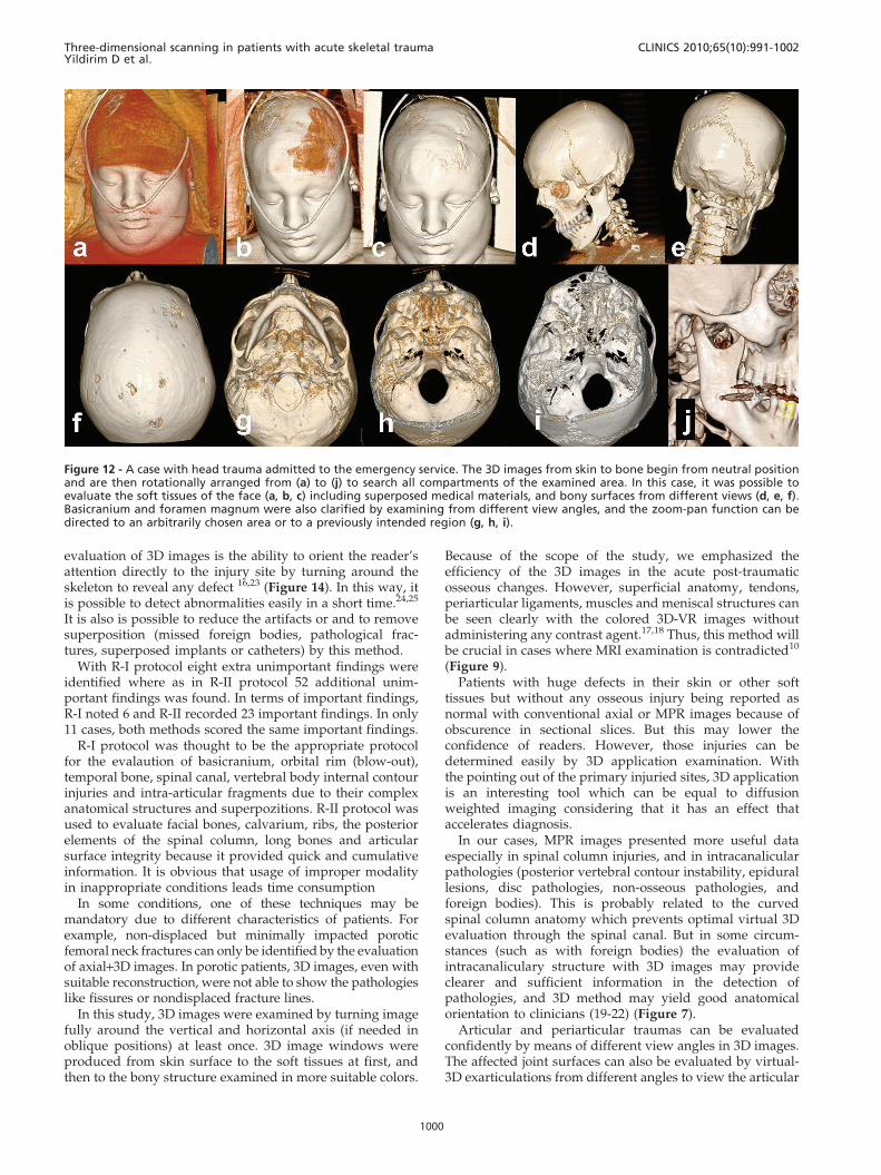
Figure 12 - A case with head trauma admitted to the emergency service. The 3D images from skin to bone begin from neutral positionand are then rotationally arranged from (a) to (j) to search all compartments of the examined area. In this case, it was possible toevaluate the soft tissues of the face (a, b, c) including superposed medical materials, and bony surfaces from different views (d, e, f).Basicranium and foramen magnum were also clarified by examining from different view angles, and the zoom-pan function can bedirected to an arbitrarily chosen area or to a previously intended region (g, h, i).
Three-dimensional scanning in patients with acute skeletal traumaYildirim D et al.
CLINICS 2010;65(10):991-1002
1000
surface integrity (Figure 10). Foreign bodies, fixationdevices, plaster casts and splints which may hamper theimage quality also can be virtually removed.22 In pediatricpatients, evaluation of the epiphyseal lines may beimpossible with axial images due to misleading variations.Also, it may be difficult to reveal the fracture orientationonly with MPR sections. All the epiphyseal lines can beeasily evaluated by the 3D images, so that injury character-ization (according to Salter-Harris categorization) can alsobe made confidently21 (Figure 11).
Due to the high resolution, it is possible to differentiateavulsion nonavulsion, separated fragments and ossifiedcomponents. Osseous contours must be examined clearly inthe 3D images especially confirming the conventional axialslices. In all cases, especially in maxillofacial traumas, wholeimages formed from the skin to the bone surface should beexamined step by step to to assess the primary injury site(Figure 12, Figure 13).
Considering all the points in Table I, the measuredaverage score for R-I was 1.25; while it was recorded as 1.99for R-II. And also to the all evaluated data, it was seen that3D scans were fast and more efficient in providing goodorientation for clinicians.
In summary, 3D images must be adjusted from the skin tothe bony surfaces by changing the window settings. Thewhole image should be examined by being turned fully atleast once around the axial and coronal planes. If necessary,artifact-producing implants, splints or fixators can be
extracted in the virtual settings. Porotic bones, deepstructures (temporal, facial, basicranial bony structure), orthe spinal column should not be evaluated by 3D imagesonly. These areas must be examined mainly with MPRimages because of their superiority to 3D imaging in theseregions. Injured articular surface integrity can be examinedwith virtually exarticulated images. It can also be said thatexamining the ligamentous or meniscal anatomy withcoloured VR-MPR images may provide more detailedinformation (especially in patients whom MRI contrendi-cated for) than 3D imaging.
In conclusion, imaging the injured skeleton in a traumapatient can be evaluated in twelve minutes with dual sourceMDCT sysem. It must be rotated by it self in whole axes atleast once. Virtual inspection, virtual exarticulation ispossible with 3D images. 3D-CT imaging is a perfectmethod for evaluating unstable or MRI-incompatible cases,and does not need direct graphy correlation. Because ofthese numerous utilities, 3D images must be created andevaluated for all trauma cases.
REFERENCES
1. El-Khoury GY, Bennett DL, Ondr GJ. Multidetector-row computedtomography. J Am Acad Orthop Surg. 2004;12:1–5.
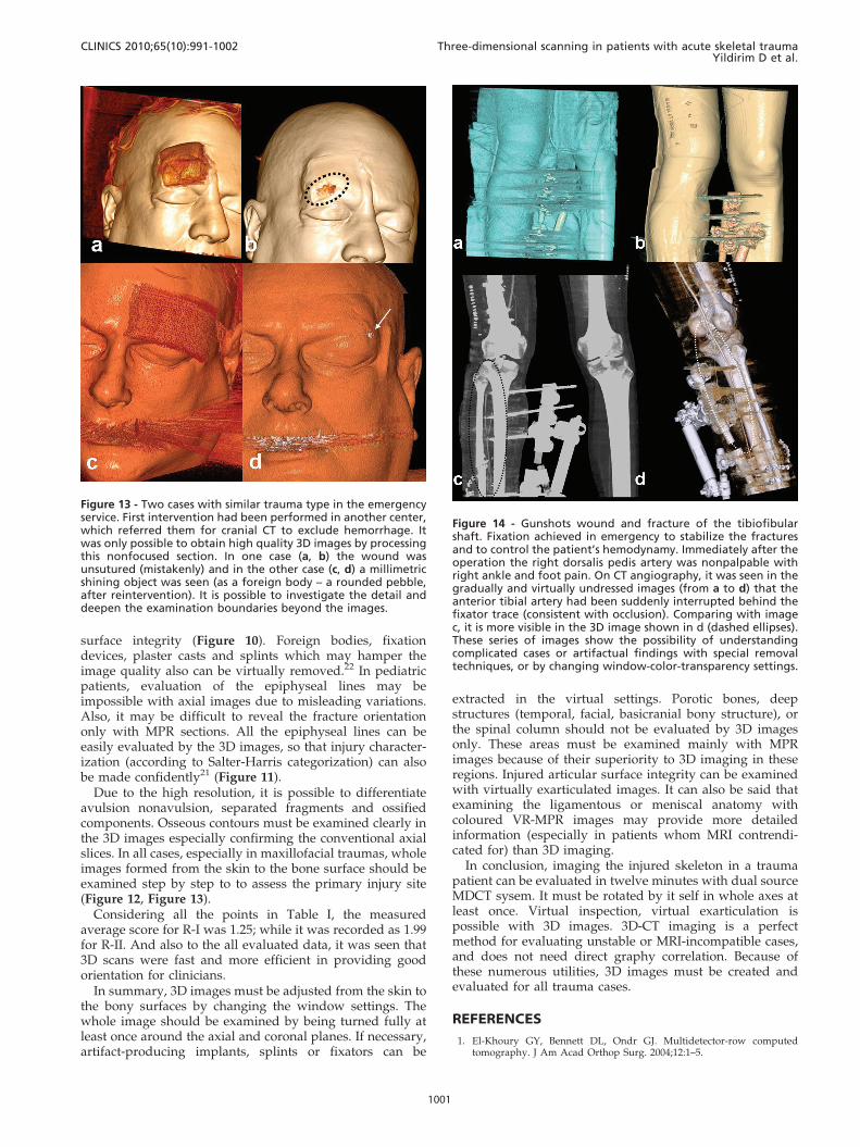
Figure 13 - Two cases with similar trauma type in the emergencyservice. First intervention had been performed in another center,which referred them for cranial CT to exclude hemorrhage. Itwas only possible to obtain high quality 3D images by processingthis nonfocused section. In one case (a, b) the wound wasunsutured (mistakenly) and in the other case (c, d) a millimetricshining object was seen (as a foreign body – a rounded pebble,after reintervention). It is possible to investigate the detail anddeepen the examination boundaries beyond the images.
Figure 14 - Gunshots wound and fracture of the tibiofibularshaft. Fixation achieved in emergency to stabilize the fracturesand to control the patient’s hemodynamy. Immediately after theoperation the right dorsalis pedis artery was nonpalpable withright ankle and foot pain. On CT angiography, it was seen in thegradually and virtually undressed images (from a to d) that theanterior tibial artery had been suddenly interrupted behind thefixator trace (consistent with occlusion). Comparing with imagec, it is more visible in the 3D image shown in d (dashed ellipses).These series of images show the possibility of understandingcomplicated cases or artifactual findings with special removaltechniques, or by changing window-color-transparency settings.
CLINICS 2010;65(10):991-1002 Three-dimensional scanning in patients with acute skeletal traumaYildirim D et al.
1001
2. Dalrymple NC, Prasad SR, Freckleton MW, Chintapalli KN. Informaticsin radiology (infoRAD): introduction to the language of three-dimen-sional imaging with multidetector CT. Radiographics 2005;25:1409–28,doi: 10.1148/rg.255055044.
3. Medina LS. Three-dimensional CT maximum intensity projections of thecalvaria: a new approach for diagnosis of craniosynostosis and fractures.AJNR Am J Neuroradiol. 2000;21:1951-4.
4. Wintermark M, Mouhsine E, Theumann N, Mordasini P, van Melle G,Leyvraz PF, et al. Thoracolumbar spine fractures in patients who havesustained severe trauma: depiction with multi-detector row CT.Radiology. 2003;227:681–9, doi: 10.1148/radiol.2273020592.
5. Suess C, Chen X. Dose optimization in pediatric CT: current technologyand future innovations. Pediatr Radiol. 2002;32:729–34, doi: 10.1007/s00247-002-0800-x.
6. Novelline RA, Rhea JT, Rao PM, Stuk JL. Helical CT in emergencyradiology. Radiology. 1999;213:321–39.
7. Philipp MO, Kubin K, Hormann M, Metz VM. Radiological emergencyroom management with emphasis on multidetector-row CT. Eur JRadio.l 2003;48:2–4.
8. Prokop A, Hotte H, Kruger K, Rehm KE, Isenberg J, Schiffer G. MultisliceCT in diagnostic work-up of polytrauma [in German]. Unfallchirurg.2006;109:545–50, doi: 10.1007/s00113-006-1086-5.
9. Gralla J, Spycher F, Pignolet C, Ozdoba C, Vock P, Hoppe H. Evaluationof a 16-MDCT scanner in an emergency department: initial clinicalexperience and workflow analysis. AJR. 2005; 185:232–8.
10. Ptak T, Rhea J, Novelline R. Experience with a continuous, single-passwhole-body multidetector CT protocol for trauma: the three-minutemultiple trauma CT scan. Emerg Radiol. 2001;8:250–6, doi: 10.1007/PL00011915.
11. Roos JE, Desbiolles LM, Willmann JK, Weishaupt D, Marincek B, HilfikerPR. Multidetector-row helical CT: analysis of time management andworkflow. Eur Radiol. 2002;12:680–5.
12. Pretorius ES, Fishman EK. Volume-rendered threedimensional spiral CT:musculoskeletal applications. RadioGraphics. 1999; 19:1143–60.
13. Tomazevic D, Likar B, Pernus F. Reconstruction-based 3D/2D imageregistration. Med Image Comput Comput Assist Interv Int Conf MedImage Comput Comput Assist Interv. 2005;8:231-8.
14. van Gennip EM, Heiska K, Kemerink GJ, Ratib O, Rechid R, van denBroeck R, et al. Overview of CAPACITY data. Int J Biomed Comput.1992;30:173-80.
15. Eisenberg JM. Clinical economics: a guide to the economic analysis ofclinical practices. JAMA. 1989;262:2879-886, doi: 10.1001/jama.262.20.2879.
16. Fayad LM, Corl F, Fishman EK. Pediatric skeletal trauma: use ofmultiplanar reformatted and three-dimensional 64-row multidetector CTin the emergency department. Radiographics. 2009;29:135-50, doi: 10.1148/rg.291085505.
17. Coulier B. Direct 3D imaging of the knee menisci during 16-rowmultislice CT arthrography. JBR-BTR. 2006;89:291-7.
18. Ohashi K, El-Khoury GY, Bennett DL. MDCT of tendon abnormalitiesusing volume-rendered images. AJR Am J Roentgenol. 2004;182:161-5.
19. Lucey BC, Stuhlfaut JW, Hochberg AR, Varghese JC, Soto JA. Evaluationof blunt abdominal trauma using PACS-based 2D and 3D MDCTreformations of the lumbar spine and pelvis. AJR Am J Roentgenol.2005;185:1435-40, doi: 10.2214/AJR.04.1396.
20. Anderson SW, Lucey BC, Varghese JC, Soto JA. Sixty-four multi-detectorrow computed tomography in multitrauma patient imaging: earlyexperience. Curr Probl Diagn Radiol. 2006;35:188-98, doi: 10.1067/j.cpradiol.2006.06.004.
21. Geijer M, El-Khoury GY. MDCT in the evaluation of skeletal trauma:principles, protocols, and clinical applications. Emerg Radiol. 2006;13:7-18, doi: 10.1007/s10140-006-0509-5.
22. Karcaaltincaba M. MDCT angiography in patients with traumaticextremity injuries. AJR Am J Roentgenol. 2006;187:W129, doi: 10.2214/AJR.06.5050.
23. Buckwalter KA, Farber JM. Application of multidetector CT in skeletaltrauma. Semin Musculoskelet Radiol. 2004;8:147–56, doi: 10.1055/s-2004-829486.
24. Trojanowska A, Czekajska-Chehab E, Trojanowski P, Olszanski W,Klatka J, Drop A, et al. Comparison of multidetector row CT cross-sectional source images with multiplanar 2D-,3D- reconstructions andvirtual endoscopy in assessment of the middle ear. J Neuroradiol.2006;33:277-8.
25. Sun C, Miao F, Wang XM, Wang T, Ma R, Wang DP, et al. An initialqualitative study of dual-energy CT in the knee ligaments. Surg RadiolAnat. 2008;30:443-7, doi: 10.1007/s00276-008-0349-y.
Three-dimensional scanning in patients with acute skeletal traumaYildirim D et al.
CLINICS 2010;65(10):991-1002
1002
Related Documents