Three-Dimensional Computerized Orthognathic Surgical Treatment Planning Patrı´cia V.M. Alves, DDS, MS a,b, *, Ana M. Bolognese, DDS, MS, DSc a , Linping Zhao, PhD c Orthognathic surgery involves anatomically de- fining the deformity, establishing an appropriate or- thodontic-surgical treatment plan, and then executing the recommended treatment. The surgi- cal-orthodontic team must then not only predict the various possible outcomes based on the options available, but once agreed, must execute that plan as precisely as possible. Historically, the surgical-or- thodontic planning has relied on two-dimensional (2D) analysis of radiographic images, the lateral cephalometric film. Currently available cephalo- metric software planning uses standard osteotomies (the LeFort I, bilateral sagittal split osteotomy [BSSO], and genioplasty) and soft tissue prediction based on 2D analysis to develop a virtual treatment plan. For the surgeon, however, a 2D blueprint us- ing only the sagittal plane as a guide for executing a three-dimensional (3D) surgical procedure in multiple planes is less than ideal. Moreover, stan- dard osteotomies in such software packages cannot simulate asymmetric osteotomies, or the osteotomies that are more appropriately tailored to correct the specific deformities, such as a modi- fied LeFort I, in which to varying degrees the zy- goma are included. Therefore, each of the elements of the craniofacial structure may require a complex osteotomy pattern and individual 3D manipulation to achieve an optimal outcome. In recent years, 3D CT imaging with reconstruc- tion of 2D-acquired data has become routinely available in the clinical setting. Compared with conventional 2D dentofacial films, the 3D images provide significantly better visualization of the morphology. Thus as new tools are developed, we can navigate away from the limitations of conven- tional 2D cephalometry with 3D CT [1,2]. Today, however, use of the 3D imaging data for orthog- nathic surgical planning remains in the setting of clinical research, because there are few accepted standards or conventions for managing such 3D computational data and methodology for surgical planning [3–6]. In this article, the authors discuss CLINICS IN PLASTIC SURGERY Clin Plastic Surg 34 (2007) 427–436 a Federal University of Rio de Janeiro, Brazil b University of Illinois at Chicago, Chicago, IL, USA c Shriners Hospitals for Children-Chicago, 2211 North Oak Park Avenue, Chicago, IL 60707, USA * Corresponding author. 2018 West Adams, Chicago, IL 60612. E-mail address: [email protected] (P.V.M. Alves). - Acquisition of the three-dimensional medical images - Determination of landmarks and cephalometric analysis - Three-dimensional computerized virtual treatment objective - Case study - Summary - References 427 0094-1298/07/$ – see front matter ª 2007 Elsevier Inc. All rights reserved. doi:10.1016/j.cps.2007.04.006 plasticsurgery.theclinics.com

Welcome message from author
This document is posted to help you gain knowledge. Please leave a comment to let me know what you think about it! Share it to your friends and learn new things together.
Transcript
C L I N I C S I NP L A S T I C
S U R G E R Y
Clin Plastic Surg 34 (2007) 427–436
427
Three-Dimensional ComputerizedOrthognathic Surgical TreatmentPlanningPatrıcia V.M. Alves, DDS, MSa,b,*, Ana M. Bolognese, DDS, MS, DSca,Linping Zhao, PhDc
- Acquisition of the three-dimensionalmedical images
- Determination of landmarks andcephalometric analysis
- Three-dimensional computerized virtualtreatment objective
- Case study- Summary- References
Orthognathic surgery involves anatomically de-fining the deformity, establishing an appropriate or-thodontic-surgical treatment plan, and thenexecuting the recommended treatment. The surgi-cal-orthodontic team must then not only predictthe various possible outcomes based on the optionsavailable, but once agreed, must execute that planas precisely as possible. Historically, the surgical-or-thodontic planning has relied on two-dimensional(2D) analysis of radiographic images, the lateralcephalometric film. Currently available cephalo-metric software planning uses standard osteotomies(the LeFort I, bilateral sagittal split osteotomy[BSSO], and genioplasty) and soft tissue predictionbased on 2D analysis to develop a virtual treatmentplan. For the surgeon, however, a 2D blueprint us-ing only the sagittal plane as a guide for executinga three-dimensional (3D) surgical procedure inmultiple planes is less than ideal. Moreover, stan-dard osteotomies in such software packages cannotsimulate asymmetric osteotomies, or the
0094-1298/07/$ – see front matter ª 2007 Elsevier Inc. All righplasticsurgery.theclinics.com
osteotomies that are more appropriately tailoredto correct the specific deformities, such as a modi-fied LeFort I, in which to varying degrees the zy-goma are included. Therefore, each of theelements of the craniofacial structure may requirea complex osteotomy pattern and individual 3Dmanipulation to achieve an optimal outcome.
In recent years, 3D CT imaging with reconstruc-tion of 2D-acquired data has become routinelyavailable in the clinical setting. Compared withconventional 2D dentofacial films, the 3D imagesprovide significantly better visualization of themorphology. Thus as new tools are developed, wecan navigate away from the limitations of conven-tional 2D cephalometry with 3D CT [1,2]. Today,however, use of the 3D imaging data for orthog-nathic surgical planning remains in the setting ofclinical research, because there are few acceptedstandards or conventions for managing such 3Dcomputational data and methodology for surgicalplanning [3–6]. In this article, the authors discuss
a Federal University of Rio de Janeiro, Brazilb University of Illinois at Chicago, Chicago, IL, USAc Shriners Hospitals for Children-Chicago, 2211 North Oak Park Avenue, Chicago, IL 60707, USA* Corresponding author. 2018 West Adams, Chicago, IL 60612.E-mail address: [email protected] (P.V.M. Alves).
ts reserved. doi:10.1016/j.cps.2007.04.006
Alves et al428
our current approach to a 3D computerized visualsurgical planning system.
Acquisition of the three-dimensionalmedical images
Three-dimensionally reconstructed CT has beenavailable for a number of years; however, it hasbeen primarily used for diagnosis and visualiza-tion of the morphologic anatomy in three dimen-sions rather than formal surgical planning. Whenit is needed, a 3D solid model is generated fromthe CT data, and the surgery is performed ona physical model. Solid model surgery is not rou-tine, however, because it is limited by an addi-tional expense, and once sectioned, it requiresanother model to assess another variation. Ulti-mately such an approach is limited, in that soft tis-sue prediction cannot be assessed. Thus virtualsurgery on a data set has inherent advantagesover a solid model, in that it allows the surgeonan unlimited number of potential outcomes andthe possibility of predicting soft tissue responsewith each possible variation. The critical step willthen be translating the virtual model surgery to in-traoperative execution with the use of surgiguidesor intraoperative navigation tools. Additionally, atthis time we have limited data to program thesoft tissue response in 3D.
Recent advances in CT scan technique havebrought about reductions in both cost andexposure to radiation [6]. The application of multi-detector helical CT scanner is increasing. New CTscanners with multiple detectors (16, 64, andeven 128 detectors) can considerably reduce thetime of scanning, and therefore reduce the artifactscaused by body movement. These machines allowthe acquisition of 3D images with smaller slicethickness within acceptable radiation exposure [7].
The cone beam CT scan can perform a full scan ofthe head in around 20 seconds, and gives the pa-tient an effective dose of only 50 mSv, comparedwith about 2000 mSv from a typical conventionalCT scan of the whole head [8]. Cone-beam CT pro-duces a lower radiation dose than spiral CT, and isalmost comparable to panoramic radiographs. Italso allows secondary reconstructions, such as sag-ittal, coronal, and axial views, and 3D reconstruc-tions of various craniofacial structures because ofits volumetric data [9,10]. Beyond this statement,radiation concerns are further reduced when oneconsiders that a single CT scan replaces a numberof conventional radiographs that are now consid-ered essential for almost every orthognathic patient,such as the lateral cephalogram, occlusal, periapi-cal, and panoramic radiograph [2,11]. The resolu-tion of the soft tissue, as muscles, in cone beam
CT scan is not as good as in the helical CT scan,however. This soft tissue information needs to beobtained from MRI.
With the limitation of the clinical acceptable ra-diation exposure, the spatial resolution of multide-tector helical CT scan can reach the order of 0.3 to0.5 mm, with a slice thickness of 0.5 to 1.0 mm.The spatial resolution of cone beam CT scan canreach the order of 0.3 to 0.5 mm. This brings ana-tomical and functional information with sufficientaccuracy not only for diagnosis, but also for vir-tual craniomaxillofacial surgery planning andnavigation.
Three-dimensional cephalometry using stan-dardized CT scanning protocols has the advantagethat all measurements are life-sized scale (1:1),which allows both cross-sectional and longitudinalcomparison of 3D distances, linear projective, andorthogonal measurements. Unlike conventionalcephalometric radiography, spiral CT-based 3Dcephalometry does not necessitate standardized fix-ation of the skull during record taking, because the3D virtual scene approach allows standardized vir-tual positioning of the skull to the Frankfort hori-zontal plane [11].
Compared with the traditional cephalometric ra-diographs, cone-beam computerized tomography(CBCT) also produces images that are anatomicallytrue (1:1 in scale). Three-dimensional representa-tions from the slices can be displayed from any an-gle in any part of the skull [12–14].
Advances in both computer hardware and imageanalysis software now enable interactive display ofthe data on personal computers, with the abilityto selectively view soft or hard tissues from anyangle. Both in plane and 3D, measurement toolsallow clinicians to extract useful informationconveniently.
Technological progress makes it possible to pro-duce accurate 3D anatomical virtual models, whichis important for cephalometric analysis and surgicalplanning. Using medical image analysis software,one can build 3D virtual models from a set ofseveral axial cross-sectional slices, and performthe 3D computerized virtual treatment objective.In this article, the authors demonstrate our ap-proach to virtual surgical treatment planning usingMimics version 10.11 (Materialise Belgium, Leuven,Belgium).
The use of the medical image analysis softwarestarts with importing image data from CT andMRI. This is a critical step. Several issues must beconsidered. The scanned data should be recon-structed as axial slices, with one to one ratio so asto preserve all of the information. The data formatof the CT/MRI scan should be standardized as a Dig-ital Imaging and Communications in Medicine
Three-Dimensional Orthognathic Surgical Treatment 429
(DICOM) file. The data transfer can be performedvia a CD or DVD disc, but online systems such asPicture Archiving and Communication Systems(PACS) are preferred. The selection from a wealthof information should start from the data importstep, but not before.
The next step is the segmentation of anatomicalstructures, which is the process of outlining theshape of structures visible in the cross-sections ofa volumetric data set. Based upon the Hounsfieldscale, hard and soft tissue can be separated; eventhe structurelike airway can be defined. The voxel-based manipulation defines both the surface andvolume of an object, and allows further separationof tissues and removal of artifacts that need to becleaned (a voxel is a volume element, representinga value on a regular grid in 3D space. This is analo-gous to a pixel, which represents the smallest unit of2D image data). A 3D graphic rendering of the vol-umetric object allows navigation between voxels inthe volumetric image and the 3D graphics withzoom, rotate, and pan.
Determination of landmarksand cephalometric analysis
Despite the availability of 3D CT images for a num-ber of years, 3D cephalometric studies for the as-sessment of dentofacial skeletal abnormalities arestill at an early stage [15–21]. This is largely becauseof the lack of a practical 3D landmark system thatallows the cephalometric analysis to be performed,and compared with the conventional 2D cephalo-metric database that has been in existence for nearlya half-century.
The authors have developed a 3D cephalometriclandmark system integrated into the software thatwe have found useful for surgical planning. Thelandmarks and 3D cephalometric measurementsare based on a well-accepted anatomical landmarksystem, and tailored to fit to our application in or-thognathic surgery and treatment.
Accurate identification of landmarks requiresanatomic knowledge and experience in landmarkdefinition. Compared with conventional cephalo-metric radiography, some landmarks (eg, anteriornasal spine) are easier, whereas others (eg, sella)more difficult to define in 3D cephalometry. More-over, sometimes the definition of conventional 2Dcephalometric landmarks has to be modified be-cause of the third dimension, or new 3D cephalo-metric landmarks (eg, posterior maxillary point)have to be defined for computing 3D cephalometricplanes.
Three-dimensional landmark identification,however, requires suitable operational definitionsof the landmark location in each of the three planes
of space (X, Y, and Z). When a point is indicated onthe cephalogram image generated from CT scan, the3D point should be positioned on the bone surface.Therefore, the geometrical relationship betweencephalogram and CT image volume is a prerequisiteif one is to benefit from the combination of CT andvirtual cephalograms. This combination of 2D and3D information is the key to accurate indication oflandmarks in a repeatable way.
Landmark identification errors are considered themajor source of cephalometric error. This type of er-ror is influenced by many factors, such as the qualityof the radiographic image, the precision of land-mark definition, the reproducibility of the landmarklocation, the operator, and the registration proce-dure. Three-dimensional cephalometry provideshighly accurate measurements of lengths and anglesdefined by landmarks directly placed on the surfaceof the bones. The landmarks should be used as a cen-ter point or registration plane for the 3D cephalom-etry coordinate system in preoperative diagnosisand surgical planning references. Also, landmarksat the cranial base, foramina, canals, and suturescan be used as guides. Ono and colleagues [22] re-ported high accuracy with less than 3% measure-ment errors using a prototype of helical CT. Otherstudies for cephalometric measurements haveyielded equivalent accuracy [23,24]. A 3D cephalo-metric system enables better description of bilateralpoints as Porion (Po), Orbitale (Or), Gonion (Go),and others. This allows for a more accurate assess-ment of the asymmetries involved when planningthe surgical correction [25–27].
Three-dimensional computerized virtualtreatment objective
Once the anatomical landmark system has been es-tablished, medical image analysis software such asSimPlant CMF and Mimics (Materialise Belgium)can generate the projection on the midsagittalplane, and this can be compared with conventional2D cephalometric analysis and ideal values. To havea more accurate comparison, such software shouldallow the operator to redefine the midsagittal planeaccording to the landmarks. It should also allow thereorientation of the images, and generate the 2Dimage slices along any chosen plane.
The use of software cutting tools allows segmen-tation of bone, and varying osteotomies can besimulated. The position tools allow the translationand rotation of skeletal elements in 3D space oncethe bones are segmented. The software also has thecapacity to simulate the soft tissue response, and al-lows the superimposition of soft tissue images overthe skeletal framework. Thus various surgical op-tions can be assessed to achieve an optimal
Alves et al430
outcome. One of the advantages of 3D virtualsurgery planning is that multiple procedures canbe simulated and evaluated. Without limitationsof the cephalometric radiograph, such as represen-tation of objects that is symmetrical to the midsag-ittal plane, 3D virtual surgery allows the surgeonfreedom in simulating a complex surgical proce-dures that represent a combination of different os-teotomies with skeletal structural repositioning inall three planes.
Case study
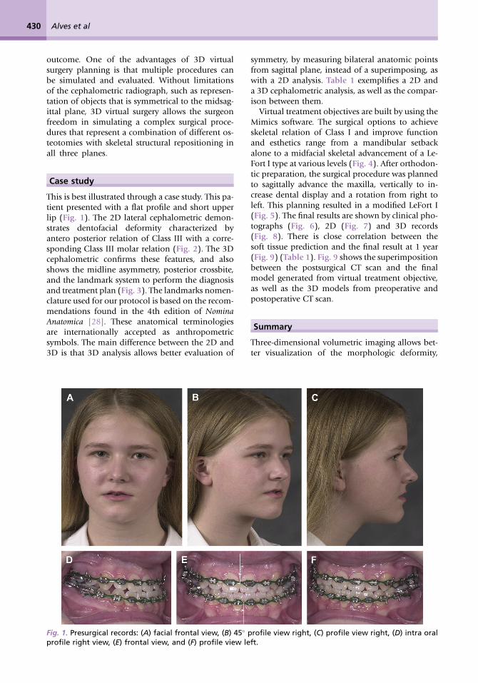
This is best illustrated through a case study. This pa-tient presented with a flat profile and short upperlip (Fig. 1). The 2D lateral cephalometric demon-strates dentofacial deformity characterized byantero posterior relation of Class III with a corre-sponding Class III molar relation (Fig. 2). The 3Dcephalometric confirms these features, and alsoshows the midline asymmetry, posterior crossbite,and the landmark system to perform the diagnosisand treatment plan (Fig. 3). The landmarks nomen-clature used for our protocol is based on the recom-mendations found in the 4th edition of NominaAnatomica [28]. These anatomical terminologiesare internationally accepted as anthropometricsymbols. The main difference between the 2D and3D is that 3D analysis allows better evaluation of
symmetry, by measuring bilateral anatomic pointsfrom sagittal plane, instead of a superimposing, aswith a 2D analysis. Table 1 exemplifies a 2D anda 3D cephalometric analysis, as well as the compar-ison between them.
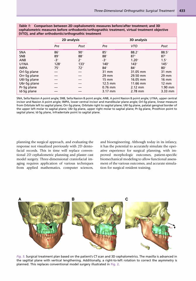
Virtual treatment objectives are built by using theMimics software. The surgical options to achieveskeletal relation of Class I and improve functionand esthetics range from a mandibular setbackalone to a midfacial skeletal advancement of a Le-Fort I type at various levels (Fig. 4). After orthodon-tic preparation, the surgical procedure was plannedto sagittally advance the maxilla, vertically to in-crease dental display and a rotation from right toleft. This planning resulted in a modified LeFort I(Fig. 5). The final results are shown by clinical pho-tographs (Fig. 6), 2D (Fig. 7) and 3D records(Fig. 8). There is close correlation between thesoft tissue prediction and the final result at 1 year(Fig. 9) (Table 1). Fig. 9 shows the superimpositionbetween the postsurgical CT scan and the finalmodel generated from virtual treatment objective,as well as the 3D models from preoperative andpostoperative CT scan.
Summary
Three-dimensional volumetric imaging allows bet-ter visualization of the morphologic deformity,
Fig. 1. Presurgical records: (A) facial frontal view, (B) 45� profile view right, (C) profile view right, (D) intra oralprofile right view, (E) frontal view, and (F) profile view left.
Three-Dimensional Orthognathic Surgical Treatment 431
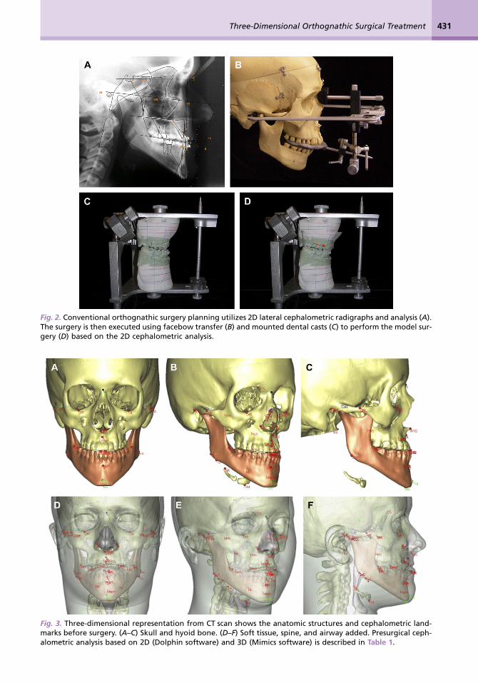
Fig. 2. Conventional orthognathic surgery planning utilizes 2D lateral cephalometric radigraphs and analysis (A).The surgery is then executed using facebow transfer (B) and mounted dental casts (C) to perform the model sur-gery (D) based on the 2D cephalometric analysis.
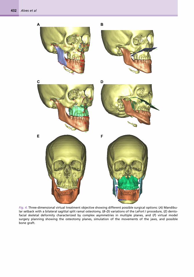
Fig. 3. Three-dimensional representation from CT scan shows the anatomic structures and cephalometric land-marks before surgery. (A–C) Skull and hyoid bone. (D–F) Soft tissue, spine, and airway added. Presurgical ceph-alometric analysis based on 2D (Dolphin software) and 3D (Mimics software) is described in Table 1.
Alves et al432
Fig. 4. Three-dimensional virtual treatment objective showing different possible surgical options: (A) Mandibu-lar setback with a bilateral sagittal split ramal osteotomy, (B–D) variations of the LeFort I procedure, (E) dento-facial skeletal deformity characterized by complex asymmetries in multiple planes, and (F) virtual modelsurgery planning showing the osteotomy planes, simulation of the movements of the jaws, and possiblebone graft.
Three-Dimensional Orthognathic Surgical Treatment 433
Table 1: Comparison between 2D cephalometric measures before/after treatment; and 3Dcephalometric measures before orthodontic/orthognathic treatment, virtual treatment objective(VTO), and after orthodontic/orthognathic treatment
2D analysis 3D analysis
Pre Post Pre VTO Post
SNA 86� 90� 85� 88.2� 88.5�
SNB 89� 88� 88� 87� 87�
ANB -3� 2� -3� 1.20� 1.5�
U1NA 128� 133� 140� 143� 145�
IMPA 75� 72� 84� 84� 80�
Orl-Sg plane — — 31 mm 31.05 mm 31 mmOrr-Sg plane — — 29 mm 29.50 mm 29 mmU6l-Sg plane — — 15 mm 16.05 mm 16 mmU6r-Sg plane — — 12.5 mm 11.66 mm 12 mmPr-Sg plane — — 0.76 mm 2.12 mm 1.90 mmId-Sg plane — — 3.17 mm 2.78 mm 3.33 mm
SNA, Sella Nasion A point angle; SNB, Sella Nasion B point angle; ANB, A point Nasion B point angle; U1NA, upper centralincisor and Nasion A point angle; IMPA, lower central incisor and mandibular plane angle; Orl-Sg plane, linear measurefrom Orbitale left to sagital plane; Orr-Sg plane, Orbitale right to sagital plane; U6l-Sg plane, palatal gengival border ofthe upper left molar to sagital plane; U6r-Sg plane, upper right molar to sagital plane; Pr-Sg plane, Prosthion point tosagital plane; Id-Sg plane, Infradentale point to sagital plane.
planning the surgical approach, and evaluating theresponse not visualized previously with 2D dento-facial records. This in time will replace conven-tional 2D cephalometric planning and plaster castmodel surgery. Three-dimensional craniofacial im-aging requires application of various techniquesfrom applied mathematics, computer sciences,
and bioengineering. Although today in its infancy,it has the potential to accurately simulate the oper-ative experience for surgical planning, with im-proved morphologic outcomes, patient-specificbiomechanical modeling to allow functional assess-ment of the various outcomes, and accurate simula-tion for surgical resident training.
Fig. 5. Surgical treatment plan based on the patient’s CT scan and 3D cephalometrics. The maxilla is advanced inthe sagittal plane with vertical lengthening. Additionally, a right-to-left rotation to correct the asymmetry isplanned. This replaces conventional model surgery illustrated in Fig. 2.
Alves et al434
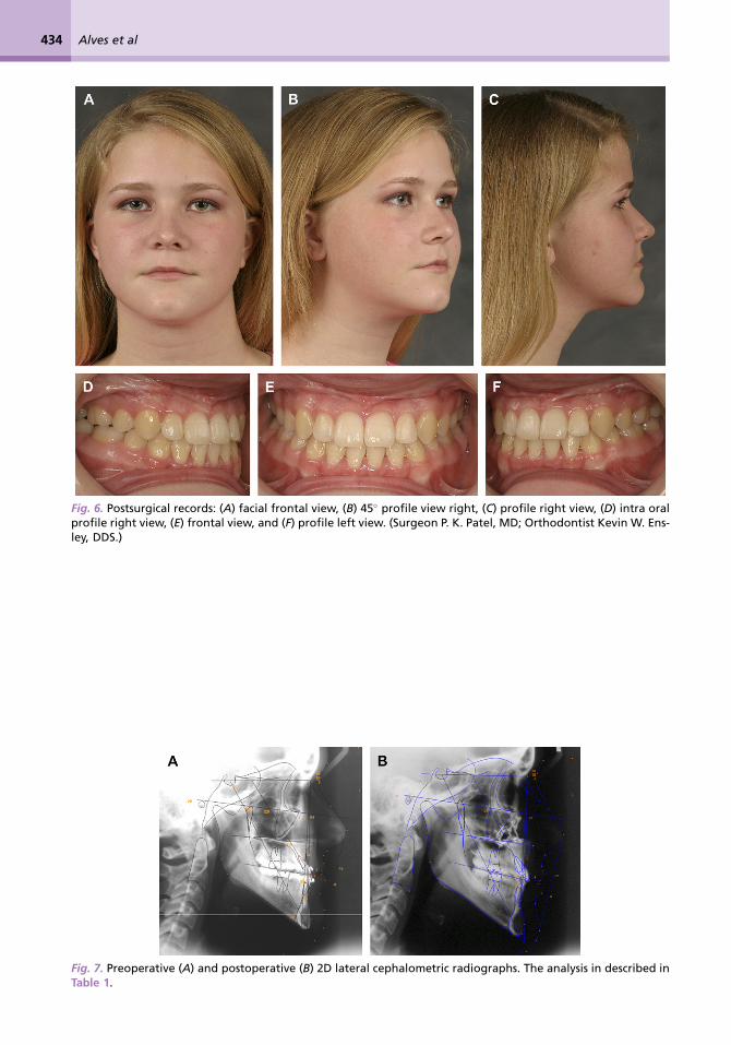
Fig. 6. Postsurgical records: (A) facial frontal view, (B) 45� profile view right, (C) profile right view, (D) intra oralprofile right view, (E) frontal view, and (F) profile left view. (Surgeon P. K. Patel, MD; Orthodontist Kevin W. Ens-ley, DDS.)
Fig. 7. Preoperative (A) and postoperative (B) 2D lateral cephalometric radiographs. The analysis in described inTable 1.
Three-Dimensional Orthognathic Surgical Treatment 435
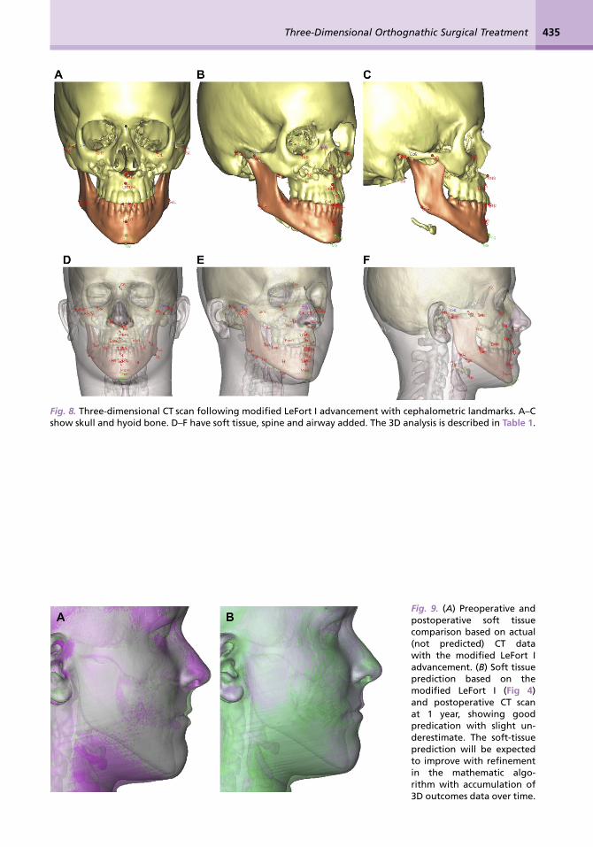
Fig. 8. Three-dimensional CT scan following modified LeFort I advancement with cephalometric landmarks. A–Cshow skull and hyoid bone. D–F have soft tissue, spine and airway added. The 3D analysis is described in Table 1.
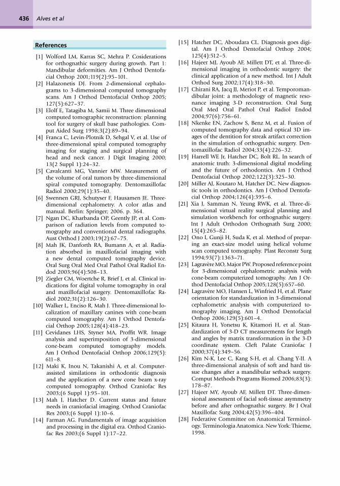
Fig. 9. (A) Preoperative andpostoperative soft tissuecomparison based on actual(not predicted) CT datawith the modified LeFort Iadvancement. (B) Soft tissueprediction based on themodified LeFort I (Fig 4)and postoperative CT scanat 1 year, showing goodpredication with slight un-derestimate. The soft-tissueprediction will be expectedto improve with refinementin the mathematic algo-rithm with accumulation of3D outcomes data over time.
Alves et al436
References
[1] Wolford LM, Karras SC, Mehra P. Cosiderationsfor orthognathic surgery during growth. Part 1:Mandibular deformities. Am J Orthod Dentofa-cial Orthop 2001;119(2):95–101.
[2] Halazonetis DJ. From 2-dimensional cephalo-grams to 3-dimensional computed tomographyscans. Am J Orthod Dentofacial Orthop 2005;127(5):627–37.
[3] Elolf E, Tatagiba M, Samii M. Three dimensionalcomputed tomographic reconstruction: planningtool for surgery of skull base pathologies. Com-put Aided Surg 1998;3(2):89–94.
[4] Franca C, Levin-Plotnik D, Sehgal V, et al. Use ofthree-dimensional spiral computed tomographyimaging for staging and surgical planning ofhead and neck cancer. J Digit Imaging 2000;13(2 Suppl 1):24–32.
[5] Cavalcanti MG, Vannier MW. Measurement ofthe volume of oral tumors by three-dimensionalspiral computed tomography. DentomaxillofacRadiol 2000;29(1):35–40.
[6] Swennen GRJ, Schutyser F, Hausamen JE. Three-dimensional cephalometry. A color atlas andmanual. Berlin: Springer; 2006. p. 364.
[7] Ngan DC, Kharbanda OP, Geently JP, et al. Com-parison of radiation levels from computed to-mography and conventional dental radiographs.Aust Orthod J 2003;19(2):67–75.
[8] Mah JK, Danforth RA, Bumann A, et al. Radia-tion absorbed in maxillofacial imaging witha new dental computed tomography device.Oral Surg Oral Med Oral Pathol Oral Radiol En-dod 2003;96(4):508–13.
[9] Ziegler CM, Woertche R, Brief J, et al. Clinical in-dications for digital volume tomography in oraland maxillofacial surgery. Dentomaxillofac Ra-diol 2002;31(2):126–30.
[10] Walker L, Enciso R, Mah J. Three-dimensional lo-calization of maxillary canines with cone-beamcomputed tomography. Am J Orthod Dentofa-cial Orthop 2005;128(4):418–23.
[11] Cevidanes LHS, Styner MA, Proffit WR. Imageanalysis and superimposition of 3-dimensionalcone-beam computed tomography models.Am J Orthod Dentofacial Orthop 2006;129(5):611–8.
[12] Maki K, Inou N, Takanishi A, et al. Computer-assisted similations in orthodontic diagnosisand the application of a new cone beam x-raycomputed tomography. Orthod Craniofac Res2003;(6 Suppl 1):95–101.
[13] Mah J, Hatcher D. Current status and futureneeds in craniofacial imaging. Orthod CraniofacRes 2003;(6 Suppl 1):10–6.
[14] Farman AG. Fundamentals of image acquisitionand processing in the digital era. Orthod Cranio-fac Res 2003;(6 Suppl 1):17–22.
[15] Hatcher DC, Aboudara CL. Diagnosis goes digi-tal. Am J Orthod Dentofacial Orthop 2004;125(4):512–5.
[16] Hajeer MJ, Ayoub AF, Millett DT, et al. Three-di-mensional imaging in orthodontic surgery: theclinical application of a new method. Int J AdultOrthod Surg 2002;17(4):318–30.
[17] Chirani RA, Jacq JJ, Meriot P, et al. Temporoman-dibular joint: a methodology of magnetic reso-nance imaging 3-D reconstruction. Oral SurgOral Med Oral Pathol Oral Radiol Endod2004;97(6):756–61.
[18] Nkenke EN, Zachow S, Benz M, et al. Fusion ofcomputed tomography data and optical 3D im-ages of the dentition for streak artifact correctionin the simulation of orthognathic surgery. Den-tomaxillofac Radiol 2004;33(4):226–32.
[19] Harrell WE Jr, Hatcher DC, Bolt RL. In search ofanatomic truth: 3-dimensional digital modelingand the future of orthodontics. Am J OrthodDentofacial Orthop 2002;122(3):325–30.
[20] Miller AJ, Koutaro M, Hatcher DC. New diagnos-tic tools in orthodontics. Am J Orthod Dentofa-cial Orthop 2004;126(4):395–6.
[21] Xia J, Samman N, Yeung RWK, et al. Three-di-mensional virtual reality surgical planning andsimulation workbench for orthognathic surgery.Int J Adult Orthodon Orthognath Surg 2000;15(4):265–82.
[22] Ono I, Gunji H, Suda K, et al. Method of prepar-ing an exact-size model using helical volumescan computed tomography. Plast Reconstr Surg1994;93(7):1363–71.
[23] Lagravere MO, Major PW. Proposed reference pointfor 3-dimensional cephalometric analysis withcone-beam computerized tomography. Am J Or-thod Dentofacial Orthop 2005;128(5):657–60.
[24] Lagravere MO, Hansen L, Winfried H, et al. Planeorientation for standardization in 3-dimensionalcephalometric analysis with computerized to-mography imaging. Am J Orthod DentofacialOrthop 2006;129(5):601–4.
[25] Kitaura H, Yonetsu K, Kitamori H, et al. Stan-dardization of 3-D CT measurements for lengthand angles by matrix transformation in the 3-Dcoordinate system. Cleft Palate Craniofac J2000;37(4):349–56.
[26] Kim N-K, Lee C, Kang S-H, et al. Chang Y-II. Athree-dimensional analysis of soft and hard tis-sue changes after a mandibular setback surgery.Comput Methods Programs Biomed 2006;83(3):178–87.
[27] Hajeer MY, Ayoub AF, Millett DT. Three-dimen-sional assessment of facial soft-tissue asymmetrybefore and after orthognathic surgery. Br J OralMaxillofac Surg 2004;42(5):396–404.
[28] Federative Committee on Anatomical Terminol-ogy. Terminologia Anatomica. New York: Thieme,1998.
Related Documents