Caledonian Medium Voltage Cables Three Core Cables to IEC 60502 APPLICATIONS: ▓ The three core cables are designed for distribution of electrical power with nominal voltage Uo/U ranging from 1.8/3KV to 26/35KV and frequency 50Hz. They are suitable for installation mostly in power supply stations, indoors and in cable ducts, outdoors, underground and in water as well as for installation on cable trays for industries, switchboards and power stations. STANDARD: ▓ PVC/PE/LSZH Oversheath Armour(optional) Binder Insulation Screen Conductor Conductor Screen XLPE/EPR/HEPR Insulation Metallic Screen PVC/PE/LSZH Separation Sheath(optional) IEC 60502 Part 1(1.8/3KV) IEC 60502 Part 2(3.6/6KV to 18/30KV) CONSTRUCTION: ▓ Conductor: Plain annealed copper or aluminium complying with IEC 60228 class 1 or 2. Conductor Screen: The conductor screen consists of an extruded layer of non metallic, semi-conducting compound applied on top of a semi-conducting tape. The conductor screen is applied under triple extrusion process over the conductor along with the insulation and the insulation screen. The extruded semi-conducting compound is firmly bonded to the insulation to exclude all air voids and can be easily hand stripped on site. The conductor screen is not necessary for both PVC and EPR/HEPR insulated 1.8/3.6KV and 3.6/6KV cables. Insulation: Insulation is of polyvinyl chloride (PVC) intended for 1.8/3.6KV and 3.6/6KV cables, cross-linked polyethylene compound (XLPE) or ethylene propylene rubber (EPR/ HEPR). Table 1. Insulation Thickness Of XLPE Or EPR/HEPR Insulation Nom. Cross Section Area Insulation Thickness at Nom. Voltage 1.8/3kV (Um=3.6kV) 3.6/6kV (Um=7.2kV) 6/10KV (Um=12KV) 8.7/15KV (Um=17KV) 12/20KV (Um=24KV) 18/30KV (Um=36KV) 21/35KV (Um=42KV) 26/35KV (Um=42KV) mm² mm mm mm mm mm mm mm mm XLPE/EPR XLPE EPR XLPE/EPR XLPE/EPR XLPE/EPR XLPE/EPR XLPE/EPR XLPE/EPR Unscreened Screened 10 2.0 2.5 3.0 2.5 - - - - - - 16 2.0 2.5 3.0 2.5 3.4 - - - - - 25 2.0 2.5 3.0 2.5 3.4 4.5 - - - - 35 2.0 2.5 3.0 2.5 3.4 4.5 5.5 - - - 50 – 185 2.0 2.5 3.0 2.5 3.4 4.5 5.5 8.0 9.3 10.5 240 2.0 2.6 3.0 2.6 3.4 4.5 5.5 8.0 9.3 10.5 300 2.0 2.8 3.0 2.8 3.4 4.5 5.5 8.0 9.3 10.5 400 2.0 3.0 3.0 3.0 3.4 4.5 5.5 8.0 9.3 10.5 500 - 1600 2.2-2.8 3.2 3.2 3.2 3.4 4.5 5.5 8.0 9.3 10.5

Welcome message from author
This document is posted to help you gain knowledge. Please leave a comment to let me know what you think about it! Share it to your friends and learn new things together.
Transcript
Caledonian Medium Voltage Cables
Three Core Cables to IEC 60502APPLICATIONS: ▓
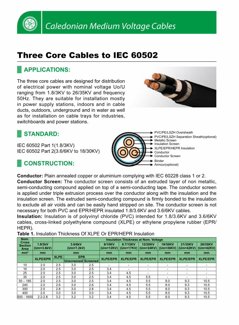
The three core cables are designed for distribution of electrical power with nominal voltage Uo/U ranging from 1.8/3KV to 26/35KV and frequency 50Hz. They are suitable for installation mostly in power supply stations, indoors and in cable ducts, outdoors, underground and in water as well as for installation on cable trays for industries, switchboards and power stations.
STANDARD: ▓ PVC/PE/LSZH Oversheath
Armour(optional)Binder
Insulation Screen
ConductorConductor Screen
XLPE/EPR/HEPR Insulation
Metallic ScreenPVC/PE/LSZH Separation Sheath(optional)
IEC 60502 Part 1(1.8/3KV)IEC 60502 Part 2(3.6/6KV to 18/30KV)
CONSTRUCTION: ▓
Conductor: Plain annealed copper or aluminium complying with IEC 60228 class 1 or 2. Conductor Screen: The conductor screen consists of an extruded layer of non metallic, semi-conducting compound applied on top of a semi-conducting tape. The conductor screen is applied under triple extrusion process over the conductor along with the insulation and the insulation screen. The extruded semi-conducting compound is firmly bonded to the insulation to exclude all air voids and can be easily hand stripped on site. The conductor screen is not necessary for both PVC and EPR/HEPR insulated 1.8/3.6KV and 3.6/6KV cables.Insulation: Insulation is of polyvinyl chloride (PVC) intended for 1.8/3.6KV and 3.6/6KV cables, cross-linked polyethylene compound (XLPE) or ethylene propylene rubber (EPR/HEPR).Table 1. Insulation Thickness Of XLPE Or EPR/HEPR Insulation
Nom. Cross
Section Area
Insulation Thickness at Nom. Voltage1.8/3kV
(Um=3.6kV)3.6/6kV
(Um=7.2kV)6/10KV
(Um=12KV)8.7/15KV
(Um=17KV)12/20KV
(Um=24KV)18/30KV
(Um=36KV)21/35KV
(Um=42KV)26/35KV
(Um=42KV)mm² mm mm mm mm mm mm mm mm
XLPE/EPR XLPE EPR XLPE/EPR XLPE/EPR XLPE/EPR XLPE/EPR XLPE/EPR XLPE/EPRUnscreened Screened10 2.0 2.5 3.0 2.5 - - - - - -16 2.0 2.5 3.0 2.5 3.4 - - - - -25 2.0 2.5 3.0 2.5 3.4 4.5 - - - -35 2.0 2.5 3.0 2.5 3.4 4.5 5.5 - - -
50 – 185 2.0 2.5 3.0 2.5 3.4 4.5 5.5 8.0 9.3 10.5240 2.0 2.6 3.0 2.6 3.4 4.5 5.5 8.0 9.3 10.5300 2.0 2.8 3.0 2.8 3.4 4.5 5.5 8.0 9.3 10.5400 2.0 3.0 3.0 3.0 3.4 4.5 5.5 8.0 9.3 10.5
500 - 1600 2.2-2.8 3.2 3.2 3.2 3.4 4.5 5.5 8.0 9.3 10.5

45www.addison-cables.com
Medium Voltage Cables to IEC 60502Insulaton Screen: The insulation screen consists of an extruded layer of non metallic, semi-conducting compound extruded over the insulation of each core. The extruded semi-conducting layer shall consist of bonded or cold strippable semi-conducting compound capable of removal for jointing or terminating. As an option, a semi-conducting tape may be applied over the individual cores or core assembly as a bedding for the metallic layer. The minimum thickness is 0.3 mm and the maximum resistivity is 500 Ohm-m at 90°C. The screen is tightly fitted to the insulation to exclude all air voids and can be easily hand stripped on site. The insulation screen is not necessary for both PVC and EPR/HEPR insulated 1.8/3.6KV and 3.6/6KV cables. The screen may be covered by semi-conductive water blocking swellable tape to ensure longitudinal watertightness.Inner Covering & Fillers: For cables with a collective metallic layer or cables with a metallic layer over each individual cores with additional collective metallic layers, semi-conducting inner covering and fillers shall be applied over the laid up cores. The inner covering and fillers are made of non hygroscopic material like polypropylene, except if the cable is to be made longitudinally watertight. The inner covering is extruded in general but may be lapped if the interstices between the cores are filled.The approximate thickness of extruded inner coverings is given in Table 2:
Table 2. Approximate Thickness Of Extruded Inner CoveringsFicititous Diameter Over Laid Up Cores Approx. Thickress of Extruded Inner Covering
mm mm
> <
- 25 1.0
25 35 1.2
35 45 1.4
45 60 1.6
60 80 1.8
80 - 2.0
*The approximate thickness of lapped inner coverings shall be 0.4mm for fictitious diameters over the laid up cores up to and including 40mm and 0.6mm for larger diameter.
Metallic Layer: The metallic layer may be applied over the individual cores or the core assembly collectively. The following types of metallic layers are provided:
1) Metallic Screen 2) Concentric Conductor 3) Metallic Sheath 4) Metallic Armour
The metallic screen shall consist of either copper tapes or a concentric layer of copper wires or a combination of tapes and wires. The concentric conductor is applied directly over the inner covering. The metallic sheath consists of lead or lead alloy applied as a tightly fitting seamless tube. The metallic armour consists of either flat wire armour, round wire armour, and double tape armour.

Caledonian Medium Voltage Cables
Table 3. Minimum Total Cross Section Of Metallic Screen Nom. Cross-Section
Area of CableMin. Cross-Sectionof Metallic Screen DC Resistance of the Copper Wire Screen
mm² mm² mm
up to 120 16 1.06
150-300 25 0.72
400-630 35 0.51
800-1000 50 0.35
Separation Sheath (for armoured cable): The separation sheath comprises a layer of extruded PVC, PE or LSZH applied over the laid up cores under the armour. PVC is normally of grade ST2 and PE of grade ST7. The nominal thickness is calculated by 0.02Du + 0.6mm where Du is the fictitious diameter under the sheath in mm. For cables without a lead sheath, the nominal separation sheath thickness shall not be less than 1.2mm. For cables where the separation sheath is applied over the lead sheath, the nominal separation sheath thickness shall not be less than 1.0mm.
Tabel 4. Separation ThicknessCores Diameter Approx. Thickress of
Inner Sheathmm mm
> <35 45 1.445 60 1.660 80 1.880 - 2.0
Lapped Bedding (for armoured lead sheathed cable): The lapped bedding applied to the lead sheath consists of either impregnated/synthetic compounded paper tapes or a combination of two layers of these paper tapes followed by a few layers of compounded fabulous materials. The thickness is around 1.5mm.
Armour (for armoured cable): The armour is applied over the inner covering helically. It consists of either flat galvanized steel wire armour (strip), round galvanized steel wire armour, and double steel tape armour.
Table 5. Round Armour Wire DiameterFictitious Diameter Under the Armour Armour Wire Diameter
mm mm> <- 10 1.25
10 15 1.2515 25 1.625 35 2.035 60 2.560 - 3.15
47www.addison-cables.com
Medium Voltage Cables to IEC 60502Table 6. Armour Tape Thickness
Fictitious Diameter Under the Armour Galvanized Steel / Steel Aluminum / Aluminium Alloy
mm mm mm
> <
- 30 0.2 0.5
30 70 0.5 0.5
70 - 0.8 0.8
For flat wire armour and fictitious diameter under the armour greater than 15mm, the nominal thickness of the flat steel wire diameter shall be 0.8mm.Cables with fictitious diameter under the armour up to and including 15mm, flat wire armour will not be used. The tape armour is applied helically in two layers so that the outer tape is approximately central over the gap of the inner tape. If tape armour is used, the inner covering shall be reinforced by taped bedding.
Over Sheath: Overall sheath comprises a layer of extruded either thermoplastic compound (PVC ST3 type or PE ST7 type) or elastomeric compound (polychlorprene CSP or chlorosulfonated PE). The nominal oversheath thickness is calculated by 0.035D+1 where D is the fictitiuous diameter immediately under the oversheath in mm. For unarmoured cables and cables with the oversheath not applied over the armour, metallic screen or concentric conductor, the nominal oversheath thickness shall not be less than 1.4mm. And for cables with oversheath applied over the armour, metallic screen or concentric conductor, the nominal oversheath thickness shall not be less than 1.8mm.
PHYSICAL PROPERTIES: ▓
Operating Temperature: up to 70°C (PVC insulation); up to 90°C (XLPE or EPR insulation)Temperature Range: -5°C ( PVC sheath ); -20°C ( PE sheath )Short Circuit Temperature( 5 seconds maximum duration ): 140-160 °C (PVC insulation); 250°C (XLPE or EPR insulation)Bending Radius: 15 x OD
Table 7. Nominal /Operating /Testing Voltages Rated Voltage Uo/U Operating Voltage (Um) Testing Voltage (rms)
1.8/3KV 3.6KV 6.5KV
3.6/6KV 7.2KV 12.5KV
6/10KV 12KV 21KV
8.7/15KV 17.5KV 30.5KV
12/20KV 24KV 42KV
18/30KV 36KV 63KV
21/35KV 42KV 73.5(53)*KV
26/35KV 42KV 91(65)*KV
*21/35KV and 26/35kV power frequency voltage test can be made under the following conditions: 2.5Uo x 30mins or 3.0Uo x 15mins. Numbers in brackets refer to the test values for 3.0Uo x 1.5mins.

Caledonian Medium Voltage Cables
Three Core 1.8/3KV (Um=3.6KV) Dimensional Data
Unarmoured Cables Steel Round-Wire Armoured CablesNom.
Cross-Section
Area
Nom.InsulationThickness
CopperTape
Thickness
CopperWire
ScreenArea*
Nom.Sheath
Thickness
Approx.Overall
Diameter
Approx.Weight
Nom.Bedding
Thickness
ArmourWireSize
Nom.Sheath
Thickness
Approx.Overall
Diameter
Approx.Weight
CU AL CU AL
mm² mm mm mm² mm mm kg/km mm mm mm mm kg/km
10 2.0 0.1 16 1.8 23 650 460 1.2 1.6 1.8 28 1480 1290
16 2.0 0.1 16 1.8 24 840 540 1.2 1.6 1.9 29 1720 1410
25 2.0 0.1 16 1.8 26 1160 680 1.2 1.6 1.9 32 2130 1650
35 2.0 0.1 16 1.8 29 1490 820 1.2 2.0 2.1 36 2810 2140
50 2.0 0.1 16 1.9 32 1900 1000 1.2 2.0 2.2 39 3340 2450
70 2.0 0.1 16 2.0 36 2580 1290 1.2 2.0 2.3 42 4200 2910
95 2.0 0.1 16 2.2 40 3440 1640 1.3 2.5 2.4 47 5620 3820
120 2.0 0.1 16 2.3 43 4220 1950 1.3 2.5 2.5 51 6580 4310
150 2.0 0.1 25 2.4 46 5090 2290 1.4 2.5 2.7 54 7680 4870
185 2.0 0.1 25 2.5 50 6240 2730 1.5 2.5 2.8 58 9060 5560
240 2.0 0.1 25 2.7 56 8030 3430 1.6 2.5 3.0 64 11200 6600
300 2.0 0.1 25 2.8 60 9890 4100 1.6 2.5 3.1 69 13590 7500
400 2.0 0.1 35 3.1 68 12530 5150 1.8 3.15 3.4 78 17260 9880
500 2.2 0.1 35 3.3 75.7 16680 7510 1.8 3.15 3.5 84.3 21780 13025
630 2.4 0.1 35 3.5 84.9 21770 10040 1.8 3.15 3.8 94.6 27400 16050
*Optional wire screen can be provided in combination of copper tapes. Nominal screen area, as stated in the table, can be supplied as standard.
Steel Flat Wire Armoured Cables Double Steel Tape Armoured Cables
Nom.Cross-Section
Area
Nom.Bedding
Thickness
ArmourWireSize
Nom.SheathThickness
Approx.Overall
Diameter
Approx.Weight Nom.
BeddingThickness
No of Steel Tapes x Nom
TapeThickness
Nom.Sheath
Thickness
Approx.Overall
Diameter
Approx.Weight
CU AL CU AL
mm² mm mm mm mm kg/km mm mm mm mm kg/km
10 1.2 0.8 1.8 24.5 1245 1065 1.2 2 x 0.2 1.8 23.6 925 750
16 1.2 0.8 1.8 27.1 1565 1280 1.2 2 x 0.2 1.8 26.2 1205 925
25 1.2 0.8 1.8 29.7 1975 1525 1.2 2 x 0.2 1.9 29.0 1590 1145
35 1.2 0.8 1.9 32.5 2420 1805 1.2 2 x 0.2 1.9 31.6 1985 1370
50 1.2 0.8 2.0 35 2860 2080 1.2 2 x 0.2 2.0 34.1 2400 1605
70 1.2 0.8 2.1 38.7 3685 2525 1.2 2 x 0.5 2.2 39.5 3570 2410
95 1.3 0.8 2.2 42.9 4695 3080 1.3 2 x 0.5 2.3 43.7 4570 2950
120 1.3 0.8 2.3 46.4 5650 3585 1.3 2 x 0.5 2.4 46.1 5510 3440
150 1.4 0.8 2.4 49.6 6630 4085 1.4 2 x 0.5 2.6 50.6 6500 3955
185 1.5 0.8 2.6 54.1 7990 4820 1.5 2 x 0.5 2.7 54.9 7825 4650
240 1.6 0.8 2.7 59.2 10060 5790 1.6 2 x 0.5 2.8 60.0 9825 5600
300 1.6 0.8 2.9 64.6 12230 6865 1.6 2 x0.5 3.0 65.4 12030 6660
400 1.8 0.8 3.1 71.0 15200 8280 1.8 2 x 0.5 3.2 71.8 14970 8055
500 1.8 0.8 3.3 79.5 19090 10255 1.8 2 x 0.8 3.5 80.5 18880 10035
630 1.8 0.8 3.6 89.8 24400 12920 1.8 2 x 0.8 3.8 92.3 25070 13620

49www.addison-cables.com
Medium Voltage Cables to IEC 60502
Electrical Data
Nom.Cross-Section
Area
D C Resistance
CU / AL
A C Resistance
CU / AL
Short Circuit Rating of
ConductorCU / AL1 sec
Capaci-tance
Charging Current
Short Circuit Rating of
Copper Wire Screen Per
Core1 sec
Short Circuit Rating of
Copper Tape Screen Per
Core1 sec
Reactance Inductance
mm² µΩ/m µΩ/m kA pF/m mA/m kA kA µΩ/m nH/m
10 1830/3080 2330/3920 1.4/0.9 160 0.25 2.6 0.4 101 390
16 1150/1910 1460/2420 2.2/1.4 180 0.27 2.6 0.4 98 370
25 727/1200 929/1538 3.6/2.3 220 0.29 2.6 0.4 95 350
35 524/868 668/1113 5.0/3.2 250 0.31 2.6 0.5 92 330
50 387/641 494/822 6.8/4.4 270 0.33 2.6 0.5 88 310
70 268/443 343/568 9.8/6.3 310 0.35 2.6 0.6 84 290
95 193/320 248/410 13.3/8.5 350 0.38 2.6 0.6 81 270
120 153/253 196/325 17.2/11.0 380 0.46 2.6 0.7 79 250
150 124/206 159/265 21.2/13.5 420 0.50 2.6 0.7 77 260
185 99.1/164 128/211 26.6/17.0 460 0.56 2.6 0.8 76 250
240 75.4/125 98/161 34.9/22.3 510 0.61 4.3 0.9 74 240
300 60.1/100 80/130 43.8/28.0 570 0.68 4.3 1.0 73 250
400 47.0/77.8 64/102 57.3/36.6 590 0.70 5.8 1.1 71 240
500 36.6/60.5 57/81 72.3/46.2 610 0.72 5.8 1.2 69 230
630 28.3/46.9 42/64 91.2/58.3 630 0.74 5.8 1.3 67 220
Three Core 3.8/6.6KV (Um=7.2KV) Dimensional Data
Unarmoured Cables Steel Round-Wire Armoured Cables
Nom.Cross-Section
Area
Nom.InsulationThickness
CopperTape
Thickness
CopperWire
ScreenArea*
Nom.Sheath
Thickness
Approx.Overall
Diameter
Approx.Weight Nom.Bedding
Thickness
ArmourWireSize
Nom.Sheath
Thickness
Approx.Overall
Diameter
Approx.Weight
CU AL CU AL
mm² mm mm mm² mm mm kg/km mm mm mm mm kg/km
10 2.5 0.1 16 2.0 30 980 790 1.2 2.0 2.1 36 2310 2120
16 2.5 0.1 16 2.0 31 1190 890 1.2 2.0 2.2 38 2600 2290
25 2.5 0.1 16 2.1 34 1560 1080 1.2 2.0 2.3 41 3080 2600
35 2.5 0.1 16 2.2 37 1930 1270 1.3 2.5 2.4 45 3950 3280
50 2.5 0.1 16 2.3 40 2370 1480 1.3 2.5 2.5 47 4530 3630
70 2.5 0.1 16 2.4 43 3110 1820 1.4 2.5 2.6 51 5510 4210
95 2.5 0.1 16 2.5 47 4000 2200 1.5 2.5 2.8 55 6660 4860
120 2.5 0.1 16 2.6 50 4820 2550 1.5 2.5 2.9 59 7630 5360
150 2.5 0.1 25 2.8 54 5770 2970 1.6 2.5 3.0 62 8800 6000
185 2.5 0.1 25 2.9 58 6960 3460 1.6 2.5 3.1 66 10180 6670
240 2.6 0.1 25 3.1 65 8940 4340 1.8 3.15 3.4 75 13480 8870
300 2.8 0.1 25 3.3 70 10980 5190 1.9 3.15 3.6 81 15920 10130
400 3.0 0.1 35 3.5 79 13820 6440 2.0 3.5 3.9 90 19980 12590
500 3.2 0.1 35 3.7 87 19100 10755 2.1 3.5 4.1 98 24160 14820
630 3.2 0.1 35 4.0 95 30470 13150 2.2 3.5 4.4 107 29650 17710
*Optional wire screen can be provided in combination of copper tapes. Nominal screen area, as stated in the table, can be supplied as standard.

Caledonian Medium Voltage Cables
Steel Flat Wire Armoured Cables Double Steel Tape Armoured Cables
Nom.Cross-Section
Area
Nom.Bedding
Thickness
ArmourWireSize
Nom.Sheath
Thickness
Approx.Overall
Diameter
Approx.Weight Nom.
BeddingThickness
No of Steel tapes x
nom tape thickness
Nom.Sheath
Thickness
Approx.Overall
Diameter
Approx.Weight
CU AL CU AL
mm² mm mm mm mm kg/km mm mm mm mm kg/km
10 1.2 0.8 1.8 26.9 1415 1235 1.2 2X0.2 1.8 26 1060 885
16 1.2 0.8 1.8 29.2 1725 1445 1.2 2X0.2 1.8 28.3 1340 1055
25 1.2 0.8 1.9 32.2 2165 1735 1.2 2X0.2 1.9 31.3 1735 1305
35 1.3 0.8 2.0 35.0 2645 2025 1.3 2X0.2 2.0 34.1 2170 1555
50 1.3 0.8 2.1 37.4 3075 2295 1.3 2X0.5 2.1 38.0 2950 2170
70 1.4 0.8 2.2 41.0 3915 2755 1.4 2X0.5 2.3 41.8 3795 2635
95 1.5 0.8 2.3 45.3 4840 3335 1.5 2X0.5 2.4 46.1 4810 3200
120 1.5 0.8 2.4 48.7 5915 3855 1.5 2X0.5 2.5 49.5 5770 3705
150 1.6 0.8 2.5 52.1 6930 4395 1.6 2X0.5 2.6 52.9 6775 4235
185 1.6 0.8 2.6 56.2 8265 5100 1.6 2X0.5 2.8 57.2 8120 4950
240 1.8 0.8 2.8 62.2 10440 6220 1.8 2X0.5 2.9 63.0 10250 6025
300 1.9 0.8 3.0 68.2 12780 7420 1.9 2X0.5 3.1 69.0 12570 7200
400 2.0 0.8 3.3 75.9 15970 9110 2.0 2X0.5 3.4 76.7 15740 8870
500 2.1 0.8 3.5 84.2 19940 11130 2.1 2X0.8 3.6 86.5 20550 11750
630 2.2 0.8 3.7 93.5 25120 13670 2.2 2X0.8 3.9 96.0 25830 14400
Electrical Data
Nom.Cross-Section
Area
D C Resistance
CU / AL
A C Resistance
CU / AL
Short Circuit Rating of
ConductorCU / AL1 sec
Capaci-tance
Charging Current
Short Circuit Rating of
Copper Wire Screen Per
Core1 sec
Short Circuit Rating of
Copper Tape Screen Per
Core1 sec
Reactance Inductance
mm² µΩ/m µΩ/m kA pF/m mA/m kA kA µΩ/m nH/m
10 1830/3080 2330/3920 1.4/0.9 212 0.27 2.6 0.4 132 410
16 1150/1910 1470/2420 2.2/1.4 242 0.30 2.6 0.4 124 390
25 727/1200 927/1538 3.6/2.3 272 0.33 2.6 0.4 116 370
35 524/868 668/1113 5.0/3.2 301 0.36 2.6 0.5 108 350
50 387/641 494/822 6.8/4.4 332 0.40 2.6 0.5 102 330
70 268/443 343/568 9.8/6.3 383 0.46 2.6 0.6 97 310
95 193/320 248/410 13.3/8.5 432 0.52 2.6 0.6 92 290
120 153/253 196/325 17.2/11.0 474 0.57 2.6 0.7 89 280
150 124/206 159/265 21.2/13.5 511 0.61 4.3 0.7 87 280
185 99.1/164 128/211 26.6/17.0 562 0.67 4.3 0.8 86 270
240 75.4/125 98/161 34.9/22.3 602 0.72 4.3 0.9 83 260
300 60.1/100 80/130 43.8/28.0 622 0.75 4.3 1.0 82 260
400 47.0/77.8 64/102 57.3/36.6 648 0.78 5.8 1.1 80 250
500 36.6/60.5 51/81 72.3/46.2 668 0.82 5.8 1.2 78 250
630 28.3/46.9 42/64 91.2/58.3 758 0.92 5.8 1.3 76 240

51www.addison-cables.com
Medium Voltage Cables to IEC 60502
Three Core 6/10KV (Um=12KV) Dimensional Data
Unarmoured Cables Steel Round-Wire Armoured Cables
Nom.Cross-Section
Area
Nom.InsulationThickness
CopperTape
Thickness
CopperWire
ScreenArea*
Nom.Sheath
Thickness
Approx.Overall
Diameter
Approx.Weight Nom.
BeddingThickness
ArmourWireSize
Nom.Sheath
Thickness
ApproxOverall
Diameter
Approx.Weight
CU AL CU AL
mm² mm mm mm² mm mm kg/km mm mm mm mm kg/km
16 3.4 0.1 16 2.2 36 1410 1110 1.2 2.0 2.4 42 3000 2700
25 3.4 0.1 16 2.3 39 1800 1320 1.3 2.5 2.5 46 3900 3430
35 3.4 0.1 16 2.3 41 2170 1500 1.3 2.5 2.6 49 4430 3770
50 3.4 0.1 16 2.4 44 2630 1730 1.4 2.5 2.7 52 5080 4190
70 3.4 0.1 16 2.6 48 3400 2110 1.5 2.5 2.8 56 6050 4750
95 3.4 0.1 16 2.7 52 4310 2510 1.5 2.5 2.9 60 7180 5380
120 3.4 0.1 16 2.8 55 5150 2890 1.6 2.5 3.0 63 8230 5960
150 3.4 0.1 25 2.9 58 6100 3300 1.7 2.5 3.1 67 9380 6580
185 3.4 0.1 25 3.0 62 7310 3810 1.7 3.15 3.3 72 11610 8110
240 3.4 0.1 25 3.2 69 9290 4680 1.8 3.15 3.5 79 14110 9510
300 3.4 0.1 25 3.3 73 11240 5450 1.9 3.15 3.7 84 16420 10630
400 3.4 0.1 35 3.6 81 14040 6660 2.0 3.5 3.9 92 20620 12880
500 3.4 0.1 35 3.7 88 17830 8450 2.1 3.5 4.0 99. 25090 16530
630 3.4 0.1 35 3.9 96 20030 10895 2.2 3.5 4.1 109 30880 19670
*Optional wire screen can be provided in combination of copper tapes. Nominal screen area, as stated in the table, can be supplied as standard.
Steel Flat Wire Armoured Cables Double Steel Tape Armoured Cables
Nom.Cross-Section
Area
Nom.Bedding
Thickness
ArmourWireSize
Nom.Sheath
Thickness
Approx.Overall
Diameter
Approx.Weight Nom.
BeddingThickness
No of Steel tapes x
nom tape thickness
Nom.Sheath
Thickness
Approx.Overall
Diameter
Approx.Weight
CU AL CU AL
mm² mm mm mm mm kg/km mm mm mm mm kg/km
16 1.2 0.8 2.2 39.7 2795 2515 1.2 2x0.5 2.3 40.5 2680 2395
25 1.3 0.8 2.2 42.7 3305 2885 1.3 2x0.5 2.4 43.7 3195 2775
35 1.3 0.8 2.3 45.2 3835 3215 1.3 2x0.5 2.5 46.2 3720 3100
50 1.4 0.8 2.4 47.8 4325 3570 1.4 2x0.5 2.6 48.8 4200 3445
70 1.5 0.8 2.5 51.8 5320 4185 1.5 2x0.5 2.7 52.8 5185 4050
95 1.5 0.8 2.7 56.1 6450 4875 1.5 2x0.5 2.8 56.9 6280 4700
120 1.6 0.8 2.8 59.7 7545 5510 1.6 2x0.5 2.9 60.5 7360 5325
150 1.7 0.8 2.9 63.1 8610 6150 1.7 2x0.5 3.0 63.9 8420 5950
185 1.7 0.8 3.0 67.4 10120 6995 1.7 2x0.5 3.1 68.2 9910 6780
240 1.8 0.8 3.2 73.0 12430 8205 1.8 2x0.5 3.3 73.8 12200 7970
300 1.9 0.8 3.3 78.3 14775 9455 1.9 2x0.5 3.4 79.1 14530 9200
400 2.0 0.8 3.5 85.2 17950 11190 2.0 2x0.8 3.7 87.7 18600 11850
500 2.1 0.8 3.7 92.8 21970 13270 2.1 2x0.8 3.9 95.3 22680 13990
630 2.2 0.8 4.0 102.7 27480 16160 2.2 2x0.8 4.1 105.0 28200 16910

Caledonian Medium Voltage Cables
Electrical Data
Nom.Cross-Section
Area
D C Resistance
CU / AL
A C Resistance
CU / AL
Short Circuit Rating of
ConductorCU / AL1 sec
Capaci-tance
Charging Current
Short Circuit Rating of
Copper Wire Screen Per
Core1 sec
Short Circuit Rating of
Copper Wire Screen Per
Core1 sec
Reactance Inductance
mm² µΩ/m µΩ/m kA pF/m mA/m kA kA µΩ/m nH/m
16 1150/1910 1470/2420 2.2/1.4 186 0.40 2.6 0.5 131 410
25 727/1200 927/1538 3.6/2.3 216 0.43 2.6 0.5 123 390
35 524/868 668/1113 5.0/3.2 237 0.47 2.6 0.6 115 370
50 387/641 494/822 6.8/4.4 266 0.52 2.6 0.6 109 350
70 268/443 343/568 9.8/6.3 298 0.60 2.6 0.7 103 330
95 193/320 248/410 13.3/8.5 334 0.67 2.6 0.7 99 320
120 153/253 196/325 17.2/11.0 365 0.73 2.6 0.8 96 310
150 124/206 159/265 21.2/13.5 392 0.78 4.3 0.8 93 300
185 99.1/164 128/211 26.6/17.0 430 0.86 4.3 0.9 90 290
240 75.4/125 98/161 34.9/22.3 476 0.95 4.3 0.9 87 280
300 60.1/100 80/130 43.8/28.0 524 1.05 4.3 1.0 85 270
400 47.0/77.8 64/102 57.3/36.6 580 1.16 5.8 1.1 81 260
500 36.6/60.5 51/81 72.3/46.2 630 1.26 5.8 1.2 78 250
630 28.3/46.9 42/64 91.2/58.3 690 1.36 5.8 1.3 76 240

53www.addison-cables.com
Medium Voltage Cables to IEC 60502
Three Core 8.7/15KV (Um=17.5KV) Dimensional Data
Unarmoured Cables Steel Round-Wire Armoured Cables
Nom.Cross-Section
Area
Nom.InsulationThickness
CopperTape
Thickness
CopperWire
ScreenArea*
Nom.Sheath
Thickness
Approx.Overall
Diameter
Approx.Weight Nom.
BeddingThickness
ArmourWireSize
Nom.Sheath
Thickness
Approx.Overall
Diameter
Approx.Weight
CU AL CU AL
mm² mm mm mm² mm mm kg/km mm mm mm mm kg/km
25 4.5 0.1 16 2.4 44 2100 1620 1.4 2.5 2.7 52 4560 4080
35 4.5 0.1 16 2.5 46 2510 1840 1.4 2.5 2.7 54 5080 4410
50 4.5 0.1 16 2.6 49 2980 2080 1.5 2.5 2.9 57 5740 4840
70 4.5 0.1 16 2.7 53 3760 2470 1.6 2.5 3.0 62 6770 5480
95 4.5 0.1 16 2.8 57 4700 2900 1.6 2.5 3.1 65 7890 6100
120 4.5 0.1 16 3.0 60 5590 3320 1.7 2.5 3.2 69 8970 6700
150 4.5 0.1 25 3.1 64 6560 3760 1.8 3.15 3.4 74 11030 8220
185 4.5 0.1 25 3.2 67 7800 4300 1.8 3.15 3.5 78 12490 8980
240 4.5 0.1 25 3.4 74 9820 5220 1.9 3.15 3.7 84 15040 10440
300 4.5 0.1 25 3.5 79 11800 6010 2.0 3.5 3.8 90 17920 12130
400 4.5 0.1 35 3.7 86 14620 7240 2.1 3.5 4.1 98 21360 13970
500 4.5 0.1 35 3.8 93 18160 9355 2.2 3.5 4.3 106 26490 17830
*Optional wire screen can be provided in combination of copper tapes. Nominal screen area, as stated in the table, can be supplied as standard.
Steel Flat Wire Armoured Cables Double Steel Tape Armoured Cables
Nom.Cross-Section
Area
Nom.Bedding
Thickness
ArmourWireSize
Nom.Sheath
Thickness
Approx.Overall
Diameter
Approx.Weight Nom.
BeddingThickness
No of Steel tapes x
Nom Tape Thickness
Nom.Sheath
Thickness
Approx.Overall
Diameter
Approx.Weight
CU AL CU AL
mm² mm mm mm mm kg/km mm mm mm mm kg/km
25 1.4 0.8 2.4 48.0 3915 3495 1.4 2x0.5 2.5 48.8 3770 3345
35 1.4 0.8 2.5 50.8 4510 3890 1.4 2x0.5 2.6 51.6 4350 3735
50 1.5 0.8 2.6 53.3 5020 4270 1.5 2x0.5 2.7 54.1 4855 4105
70 1.6 0.8 2.7 57.0 5990 4870 1.6 2x0.5 2.8 57.8 5815 4690
95 1.6 0.8 2.8 61.2 7170 5600 1.6 2x0.5 3.0 62.2 7010 5435
120 1.7 0.8 2.9 65.1 8340 6320 1.7 2x0.5 3.1 66.1 8170 6145
150 1.8 0.8 3.0 68.3 9440 6955 1.8 2x0.5 3.2 69.3 9260 6770
185 1.8 0.8 3.2 72.8 10990 7880 1.8 2x0.5 3.3 73.6 10760 7650
240 1.9 0.8 3.3 78.3 13370 9155 1.9 2x0.5 3.4 79.1 13120 8900
300 2.0 0.8 3.5 83.7 15760 10460 2.0 2x0.8 3.6 86.0 16360 11070
400 2.1 0.8 3.7 90.5 19050 12260 2.1 2x0.8 3.9 93.0 19750 12960
500 2.2 0.8 3.9 98.2 23160 14430 2.2 2x0.8 4.1 100.7 23900 15190

Caledonian Medium Voltage Cables
Electrical Data
Nom.Cross-Section
Area
D CResistance
CU / AL
A CResistance
CU / AL
Short Circuit Rating of
Conductor CU / AL
1 sec
Capacitance Charging Current
Short Circuit Rating of Copper
Wire ScreenPer Core
1 sec
Short Circuit Rating of
Copper Tape Screen Per
Core1 sec
Reactance Inductance
mm² µΩm µΩ/m kA pF/m mA/m kA kA µΩm nH/m
25 727/1200 927/1538 3.6/2.3 176 0.48 2.6 0.6 132 410
35 524/868 668/1113 5.0/3.2 193 0.53 2.6 0.6 123 390
50 387/641 494/822 6.8/4.4 211 0.58 2.6 0.7 116 370
70 268/443 343/568 9.8/6.3 240 0.65 2.6 0.7 110 350
95 193/320 248/410 13.3/8.5 267 0.73 2.6 0.8 105 330
120 153/253 196/325 17.2/11.0 291 0.79 2.6 0.8 102 320
150 124/206 159/265 21.2/13.5 312 0.85 4.3 0.9 98 310
185 99.1/164 128/211 26.6/17.0 340 0.93 4.3 0.9 95 300
240 75.4/125 98/161 34.9/22.3 375 1.02 4.3 1.0 91 290
300 60.1/100 80/130 43.8/28.0 411 1.12 4.3 1.1 89 280
400 47.0/77.8 64/102 57.3/36.6 454 1.24 5.8 1.2 84 270
500 36.6/60.5 51/81 72.3/46.2 504 1.34 5.8 1.3 78 250
Three Core12/20KV (Um=24KV) Dimensional Data
Unarmoured Cables Steel Round-Wire Armoured Cables
Nom.Cross-Section
Area
Nom.InsulationThickness
CopperTape
Thickness
CopperWire
ScreenArea*
Nom.Sheath
Thickness
Approx.Overall
Diameter
Approx.Weight Nom.
BeddingThickness
ArmourWireSize
Nom.Sheath
Thickness
Approx.Overall
Diameter
Approx.Weight
CU AL CU AL
mm² mm mm mm² mm mm kg/km mm mm mm mm kg/km
35 5.5 0.1 16 2.7 51 2850 2180 1.5 2.5 2.9 60 5700 5010
50 5.5 0.1 16 2.8 54 3340 2450 1.6 2.5 3.0 62 6370 5480
70 5.5 0.1 16 2.9 58 4150 2850 1.6 2.5 3.1 66 7370 6070
95 5.5 0.1 16 3.0 62 5110 3310 1.7 3.15 3.3 72 9400 7600
120 5.5 0.1 16 3.1 65 5990 3730 1.8 3.15 3.4 75 10530 8270
150 5.5 0.1 25 3.2 68 6980 4180 1.8 3.15 3.5 80 11800 8940
185 5.5 0.1 25 3.3 72 8240 4740 1.9 3.15 3.7 83 13350 9850
240 5.5 0.1 25 3.6 79 10310 5700 2.0 3.5 3.8 90 16430 11820
300 5.5 0.1 25 3.7 84 12360 6570 2.1 3.5 4.0 95 18870 13080
400 5.5 0.1 35 3.9 91 15220 7830 2.2 4.0 4.3 103 23260 15930
500 5.5 0.1 35 4.1 97 19105 10325 2.3 4.2 4.5 110 27800 19170
*Optional wire screen can be provided in combination of copper tapes. Nominal screen area, as stated in the table, can be supplied as standard.

55www.addison-cables.com
Medium Voltage Cables to IEC 60502
Steel Flat Wire Armoured Cables Double Steel Tape Armoured Cables
Nom.Cross-Section
Area
Nom.Bedding
Thickness
ArmourWireSize
Nom.Sheath
Thickness
Approx.Overall
Diameter
Approx.Weight Nom.
BeddingThickness
No of Steel tapes x
nom tape thickness
Nom.Sheath
Thickness
Approx.Overall
Diameter
Approx.Weight
CU AL CU AL
mm² mm mm mm mm kg/km mm mm mm mm kg/km
35 1.5 0.8 2.7 55.7 5150 4530 1.5 2x0.5 2.8 56.5 4975 4355
50 1.6 0.8 2.8 58.2 5675 4935 1.6 2x0.5 2.9 59.0 5495 4750
70 1.6 0.8 2.9 61.9 6685 5570 1.6 2x0.5 3.0 62.7 6490 5375
95 1.7 0.8 3.0 66.4 7945 6390 1.7 2x0.5 3.1 67.2 7735 6180
120 1.8 0.8 3.1 70.0 9110 7103 1.8 2x0.5 3.2 70.8 8890 6880
150 1.8 0.8 3.2 73.2 10240 7770 1.8 2x0.5 3.3 74.0 10010 7535
185 1.9 0.8 3.3 77.7 11840 8750 1.9 2x0.5 3.4 78.5 11600 8500
240 2.0 0.8 3.5 83.2 14270 10070 2.0 2x0.8 3.6 85.5 14870 10680
300 2.1 0.8 3.6 88.6 16730 11440 2.1 2x0.8 3.8 91.1 17400 12130
400 2.2 0.8 3.9 95.6 20130 13350 2.2 2x0.8 4.0 97.9 20820 14050
500 2.3 0.8 4.1 103.3 24310 15600 2.3 2x0.8 4.2 105.6 25050 16350
Electrical Data
Nom.Cross-Section
Area
D C Resistance
CU / AL
A C Resistance
CU / AL
Short Circuit Rating of
ConductorCU / AL1 sec
Capaci-tance
Charging Current
Short Circuit Rating of
Copper Wire Screen Per
Core1 sec
Short Circuit Rating of
Copper Tape Screen Per
Core1 sec
Reactance Inductance
mm² µΩ/m µΩ/m kA pF/m mA/m kA kA µΩ/m nH/m
35 524/868 668/1113 5.0/3.2 168 0.67 2.6 0.7 129 410
50 387/641 494/822 6.8/4.4 183 0.73 2.6 0.8 122 390
70 268/443 343/568 9.8/6.3 207 0.83 2.6 0.8 115 370
95 193/320 248/410 13.3/8.5 229 0.92 2.6 0.9 110 350
120 153/253 196/325 17.2/11.0 249 1.00 2.6 0.9 106 340
150 124/206 159/265 21.2/13.5 266 1.06 4.3 1.0 103 330
185 99.1/164 128/211 26.6/17.0 289 1.16 4.3 1.0 100 320
240 75.4/125 98/161 34.9/22.3 318 1.27 4.3 1.1 95 300
300 60.1/100 80/130 43.8/28.0 348 1.39 4.3 1.2 93 290
400 47.0/77.8 64/102 57.3/36.6 388 1.53 5.8 1.3 87 280
500 36.6/60.5 51/81 72.3/46.2 422 1.67 5.8 1.4 78 250

Caledonian Medium Voltage Cables
Three Core 18/30KV (Um=36KV) Dimensional Data
Unarmoured Cables Steel Round-Wire Armoured CablesNom.
Cross-Section
Area
Nom.InsulationThickness
CopperTape
Thickness
CopperWire
ScreenArea*
Nom.Sheath
Thickness
Approx.Overall
Diameter
Approx.Weight
Nom.Bedding
Thickness
ArmourWireSize
Nom.Sheath
Thickness
Approx.Overall
Diameter
Approx.Weight
CU AL CU ALmm² mm mm mm² mm mm kg/km mm mm mm mm kg/km50 8.0 0.1 16 3.2 65 4340 3460 1.8 3.15 3.5 75 8950 808070 8.0 0.1 16 3.3 70 5220 3930 1.9 3.15 3.6 80 10150 886095 8.0 0.1 16 3.4 74 6240 4440 1.9 3.15 3.7 84 11390 9590
120 8.0 0.1 16 3.5 77 7180 4910 2.0 3.5 3.8 89 13200 10860150 8.0 0.1 25 3.6 80 8220 5420 2.1 3.5 4.0 92 14520 11720185 8.0 0.1 25 3.7 84 9540 6040 2.1 4.0 4.1 97 17020 13510240 8.0 0.1 25 3.9 91 11720 7110 2.2 4.0 4.3 104 19810 15200300 8.0 0.1 25 4.0 95 13790 8000 2.3 4.5 4.5 108 23310 17470400 8.0 0.1 35 4.3 103 16820 9430 2.4 4.5 4.7 117 27010 19620500 8.0 0.1 35 4.5 110 21550 12880 2.5 4.5 4.9 124 31130 22610
*Optional wire screen can be provided in combination of copper tapes. Nominal screen area, as stated in the table, can be supplied as standard.
Steel Flat Wire Armoured Cables Double Steel Tape Armoured CablesNom.
Cross-Section
Area
Nom.Bedding
Thickness
ArmourWireSize
Nom.Sheath
Thickness
Approx.Oveall
Diameter
Approx.Weight
Nom.Bedding
Thickness
No of Steel tapes x
nom tapethickness
Nom.Sheath
Thickness
Approx.Overall
Diameter
Approx.Weight
CU AL CU ALmm² mm mm mm mm kg/km mm mm mm mm kg/km50 1.8 0.8 3.1 70.2 7490 6775 1.8 2x0.5 3.3 71.2 7300 658570 1.9 0.8 3.2 74.0 8590 7540 1.9 2x0.5 3.4 75.0 8390 733595 1.9 0.8 3.4 78.5 9990 8460 1.9 2x0.5 3.5 79.3 9740 8210120 2.0 0.8 3.5 82.2 11250 9270 2.0 2x0.8 3.6 84.5 11845 9875150 2.1 0.8 3.6 85.6 12510 10070 2.1 2x0.8 3.7 87.9 13120 10700185 2.1 0.8 3.7 89.8 14155 11100 2.1 2x0.8 3.9 92.3 14850 11800240 2.2 0.8 3.8 95.4 16740 12575 2.2 2x0.8 4.0 97.9 17480 13320300 2.3 0.8 4.0 100.9 19310 14120 2.3 2x0.8 4.2 103.4 20080 14900400 2.4 0.8 4.2 107.8 22840 16170 2.4 2x0.8 4.4 110.3 23660 17000500 2.5 0.8 4.4 115.5 27200 18610 2.5 2x0.8 4.6 118.0 28080 19510
Electrical Data
Nom.Cross-Section
Area
D C Resistance
CU / AL
A C Resistance
CU / AL
Short Circuit Rating of
ConductorCU / AL1 sec
Capacitance Charging Current
Short Circuit Rating of
Copper Wire Screen Per Core 1 sec
Short Circuit Rating of
Copper Tape Screen Per Core 1 sec
Reactance Inductance
mm² µΩ/m µΩ/m kA pF/m mA/m kA kA µΩ/m nH/m50 387/641 494/822 6.8/4.4 142 0.85 2.6 1.0 134 43070 268/443 343/568 9.8/6.3 159 0.95 2.6 1.0 127 40095 193/320 248/410 13.3/8.5 175 1.05 2.6 1.1 121 390120 153/253 196/325 17.2/11.0 189 1.13 2.6 1.1 117 370150 124/206 159/265 21.2/13.5 201 1.21 4.3 1.2 113 360185 99.1/164 128/211 26.6/17.0 217 1.3 4.3 1.2 109 350240 75.4/125 98/161 34.9/22.3 237 1.42 4.3 1.3 104 330300 60.1/100 80/130 43.8/28.0 258 1.55 4.3 1.4 101 320400 47.0/77.8 64/102 57.3/36.6 282 1.69 5.8 1.5 96 290500 36.6/60.5 51/81 72.3/46.2 302 1.79 5.8 1.6 78 250

57www.addison-cables.com
Medium Voltage Cables to IEC 60502
Three Core 21/35KV (Um=42KV) Dimensional Data
Unarmoured Cables Steel Round-Wire Armoured CablesNom.
Cross-Section
Area
Nom.InsulationThickness
CopperTape
Thickness
CopperWire
ScreenArea*
Nom.Sheath
Thickness
Approx.Overall
Diameter
Approx.Weight
Nom.Bedding
Thickness
ArmourWireSize
Nom.Sheath
Thickness
Approx.Overall
Diameter
Approx.Weight
CU AL CU ALmm² mm mm mm² mm mm kg/km mm mm mm mm kg/km50 9.3 0.1 16 3.2 73.9 5320 4446 1.9 3.15 3.8 87.1 10970 1009070 9.3 0.1 16 3.3 78.0 6166 4880 2.0 3.5 3.9 91.3 12220 1075095 9.3 0.1 16 3.5 81.9 7144 5430 2.1 3.5 4.0 94.5 13560 11780120 9.3 0.1 16 3.6 85.1 8232 6049 2.1 4.0 4.1 97.5 14880 13650150 9.3 0.1 25 3.7 88.6 9273 6549 2.1 4.0 4.2 100.5 16150 14060185 9.3 0.1 25 3.8 93.5 10845 7392 2.2 4.0 4.3 105.5 17840 14390240 9.3 0.1 25 4.0 98.2 12675 8310 2.3 4.5 4.5 111.5 20410 15870300 9.3 0.1 25 4.1 103.6 14960 9362 2.4 4.5 4.6 116.5 24100 18460400 9.3 0.1 35 4.3 110.0 18055 10698 2.5 4.5 4.8 124.3 28680 20560
*Optional wire screen can be provided in combination of copper tapes. Nominal screen area, as stated in the table, can be supplied as standard.
Steel Flat Wire Armoured Cables Double Steel Tape Armoured CablesNom.
Cross-Section
Area
Nom.Bedding
Thickness
ArmourWireSize
Nom.Sheath
Thickness
Approx.Oveall
Diameter
Approx.Weight
Nom.Bedding
Thickness
No of Steel tapes x
nom tape thickness
Nom.Sheath
Thickness
Approx.Overall
Diameter
Approx.Weight
CU AL CU ALmm² mm mm mm mm kg/km mm mm mm mm kg/km50 1.9 0.8 3.3 80.5 9825 8986 1.9 2x0.5 3.5 82.5 9625 878670 2.0 0.8 3.6 85.5 11015 9769 2.0 2x0.8 3.8 87.6 10825 956995 2.1 0.8 3.8 88.5 12360 10580 2.1 2x0.8 3.9 90.5 12116 10327
120 2.1 0.8 3.9 91.5 13900 11715 2.1 2x0.8 4.0 94.5 13306 11110150 2.1 0.8 4.0 94.8 15160 12440 2.1 2x0.8 4.1 97.5 14550 11830185 2.2 0.8 4.1 99.5 17500 13450 2.2 2x0.8 4.2 101.7 16810 12765240 2.3 0.8 4.2 104.1 19390 14890 2.3 2x0.8 4.4 107.5 18650 14150300 2.4 0.8 4.4 109.5 21970 16280 2.4 2x0.8 4.6 112.8 21200 15500400 2.5 0.8 4.6 116.3 25600 18430 2.5 2x0.8 4.8 118.8 24780 17600
Electrical Data
Nom.Cross-Section
Area
D C Resistance
CU / AL
A C Resistance
CU / AL
Short Circuit Rating of
ConductorCU / AL1 sec
Capacitance Charging Current
Short Circuit Rating of
Copper Wire Screen Per Core 1 sec
Short Circuit Rating of
Copper Tape Screen Per Core 1 sec
Reactance Inductance
mm² µΩ/m µΩ/m kA pF/m mA/m kA kA µΩ/m nH/m50 387/641 494/822 6.8/4.4 135 0.91 2.6 1.1 140 45070 268/443 343/568 9.8/6.3 151 1.01 2.6 1.1 134 41595 193/320 248/410 13.3/8.5 166 1.11 2.6 1.2 126 405
120 153/253 196/325 17.2/11.0 179 1.21 2.6 1.2 123 385150 124/206 159/265 21.2/13.5 189 1.29 4.3 1.3 118 375185 99.1/164 128/211 26.6/17.0 202 1.38 4.3 1.3 114 365240 75.4/125 98/161 34.9/22.3 221 1.49 4.3 1.4 109 345300 60.1/100 80/130 43.8/28.0 240 1.65 4.3 1.5 105 335400 47.0/77.8 64/102 57.3/36.6 267 1.75 5.8 1.6 101 305

Caledonian Medium Voltage Cables
Three Core 26/35KV (Um=42KV) Dimensional Data
Unarmoured Cables Steel Round-Wire Armoured CablesNom.
Cross-Section
Area
Nom.InsulationThickness
CopperTape
Thickness
CopperWire
ScreenArea*
Nom.Sheath
Thickness
Approx.Overall
Diameter
Approx.Weight
Nom.Bedding
Thickness
ArmourWireSize
Nom.Sheath
Thickness
Approx.Overall
Diameter
Approx.Weight
CU AL CU ALmm² mm mm mm² mm mm kg/km mm mm mm mm kg/km50 10.5 0.1 16 3.4 79.7 5928 5053 1.9 3.5 4.0 93.5 12050 1115070 10.5 0.1 16 3.5 83.6 6900 5634 2.0 4.0 4.1 97.5 13150 1185095 10.5 0.1 16 3.6 87.2 7863 6131 2.1 4.0 4.2 101.5 14800 12950120 10.5 0.1 16 3.8 90.7 8817 6634 2.2 4.0 4.4 105.5 16050 13800150 10.5 0.1 25 3.9 94.1 10085 7361 2.3 4.5 4.5 108.5 17420 14640185 10.5 0.1 25 4.0 99.1 11573 8120 2.3 4.5 4.6 112 19200 15700240 10.5 0.1 25 4.1 103.6 13387 9023 2.4 4.5 4.7 117 21050 16800300 10.5 0.1 25 4.3 109.2 15658 10060 2.5 4.5 4.8 122.5 24900 19100400 10.5 0.1 35 4.5 115.6 19013 11657 2.6 4.5 5.1 129 29200 21560
*Optional wire screen can be provided in combination of copper tapes. Nominal screen area, as stated in the table, can be supplied as standard.
Steel Flat Wire Armoured Cables Double Steel Tape Armoured CablesNom.
Cross-Section
Area
Nom.Bedding
Thickness
ArmourWireSize
Nom.Sheath
Thickness
Approx.Oveall
Diameter
Approx.Weight
Nom.Bedding
Thickness
No of Steel tapes x nom
tape thickness
Nom.Sheath
Thickness
Approx.Overall
Diameter
Approx.Weight
CU AL CU ALmm² mm mm mm mm kg/km mm mm mm mm kg/km50 1.9 0.8 3.5 86.5 10880 9990 1.9 2x0.8 3.7 87.5 10690 980070 2.0 0.8 3.6 90.5 12000 10795 2.0 2x0.8 3.8 91.4 10800 1059095 2.1 0.8 3.8 94.0 13360 11570 2.1 2x0.8 3.9 95.2 13110 11327
120 2.2 0.8 3.9 96.4 13705 12710 2.2 2x0.8 4.0 98.7 14300 12110150 2.3 0.8 4.0 99.5 16160 13440 2.3 2x0.8 4.1 102.1 15550 12800185 2.3 0.8 4.1 105.1 18505 14465 2.3 2x0.8 4.2 107.3 17810 13765240 2.4 0.8 4.2 109.8 20390 15890 2.4 2x0.8 4.4 112.2 19650 15150300 2.5 0.8 4.4 115.5 22970 17280 2.5 2x0.8 4.6 118.0 22200 16500400 2.6 0.8 4.6 122.1 26600 19430 2.6 2x0.8 4.8 124.6 25780 18600
Electrical Data
Nom.Cross-Section
Area
D C Resistance
CU / AL
A C Resistance
CU / AL
Short Circuit Rating of
ConductorCU / AL1 sec
Capacitance Charging Current
Short Circuit Rating of
Copper Wire Screen Per
Core 1 sec
Short Circuit Rating of
Copper Tape Screen Per
Core 1 sec
Reactance Inductance
mm² µΩ/m µΩ/m kA pF/m mA/m kA kA µΩ/m nH/m50 387/641 494/822 6.8/4.4 131 0.97 2.6 1.2 146 47070 268/443 343/568 9.8/6.3 145 1.07 2.6 1.2 139 43095 193/320 248/410 13.3/8.5 158 1.18 2.6 1.3 132 420120 153/253 196/325 17.2/11.0 169 1.26 2.6 1.3 128 400150 124/206 159/265 21.2/13.5 178 1.36 4.3 1.4 123 390185 99.1/164 128/211 26.6/17.0 185 1.44 4.3 1.4 118 380240 75.4/125 98/161 34.9/22.3 203 1.57 4.3 1.5 113 360300 60.1/100 80/130 43.8/28.0 219 1.72 4.3 1.6 109 350400 47.0/77.8 64/102 57.3/36.6 245 1.85 5.8 1.7 105 320

59www.addison-cables.com
Medium Voltage Cables to IEC 60502
Current Rating for Three Core 1.8/3KV(Um=7.2 )KV to 26/35KV(Um=42KV) XLPE InsulationUnarmored Armored
Nom.Cross-Section
Area
Buried direct in Ground
Laid in Single Way Duct Laid in Air Buried direct in
GroundLaid in Single Way
Duct Laid in Air
CU AL CU AL CU AL CU AL CU AL CU AL
mm² A A A A A A10 76 53 62 42 87 62 76 53 63 43 88 6316 101 78 87 67 109 84 101 78 88 68 110 8525 129 100 112 87 142 110 129 100 112 87 143 11135 153 119 133 103 170 132 154 119 134 104 172 13350 181 140 158 122 204 158 181 140 158 123 205 15970 221 171 193 150 253 196 220 171 194 150 253 19695 262 203 231 179 304 236 263 204 232 180 307 238
120 298 232 264 205 351 273 298 232 264 206 352 274150 334 260 297 231 398 309 332 259 296 231 397 309185 377 294 336 262 455 355 374 293 335 262 453 354240 434 340 390 305 531 415 431 338 387 304 529 415300 489 384 441 346 606 475 482 380 435 343 599 472400 553 438 501 398 696 552 541 432 492 393 683 545500 613 498 541 451 786 652 601 492 532 446 773 645630 663 568 591 501 896 762 651 562 582 496 883 755
Current Rating for Three Core 1.8/3KV(Um=7.2 )KV to 26/35KV(Um=42KV) EPR InsulationUnarmored Armored
Nom.Cross-Section
Area
Buried direct in Ground
Laid in Single Way Duct Laid in Air Buried direct in
GroundLaid in Single Way
Duct Laid in Air
CU AL CU AL CU AL CU AL CU AL CU AL
mm² A A A A A A10 73 51 59 40 82 58 73 51 60 41 82 59 16 98 76 84 65 104 80 98 76 85 66 104 81 25 125 97 109 84 135 105 125 97 109 85 136 105 35 150 116 130 101 164 127 150 116 131 101 164 127 50 176 137 154 119 195 151 177 137 155 120 197 153 70 216 167 189 147 243 189 216 168 190 147 244 190 95 258 200 227 176 296 229 257 200 227 176 296 230
120 292 227 258 201 339 263 292 227 259 201 339 264 150 328 255 291 226 385 299 327 254 291 226 385 300 185 371 289 330 257 441 343 368 288 328 257 439 343 240 429 335 384 300 519 406 424 332 381 299 513 402 300 482 378 434 340 590 462 475 374 429 338 583 459 400 545 432 494 392 678 538 534 426 485 387 666 530 500 605 492 534 445 768 638 594 486 525 440 756 630630 655 562 584 495 878 749 644 556 575 490 862 741
Current Rating Conditions: ▓
Ground Temperature: 20°C Ambient Temperature (air): 30°C Depth of Soil: 0.8 m Thermal Resistance of Soil: 1.5K•m/W
Related Documents