Thorburn Flex Inc Flexible Piping Specialist 173 Oneida Drive, Pointe-Claire, Quebec, Canada H9R 1A9 Tel.: (514) 695-8710 Fax: (514) 695-8716 TOLL-FREE 1-800-363-6613 3rd Edition NEW! Metric Conversion Adapters If we don’t have it, it’s not made! COMPLIANCES: ASME Section III, VIII, B.31.1, B31.3, B51 TUBE FITTINGS, HOSE ADAPTERS, AND LIVE SWIVEL ADAPTERS Thorburn Flex Inc Flexible Piping Specialist

Welcome message from author
This document is posted to help you gain knowledge. Please leave a comment to let me know what you think about it! Share it to your friends and learn new things together.
Transcript

Thorburn Flex IncFlexible Piping Specialist
173 Oneida Drive, Pointe-Claire, Quebec, Canada H9R 1A9
Tel.: (514) 695-8710 Fax: (514) 695-8716
TOLL-FREE 1-800-363-6613
3rd Edition
NEW!Metric
ConversionAdapters
If we don’t h
ave it,
it’s not m
ade!
COMPLIANCES: ASME Section III, VIII,B.31.1, B31.3, B51
TUBE FITTINGS, HOSE ADAPTERS, AND LIVE SWIVEL ADAPTERS
Thorburn Flex IncFlexible Piping Specialist
Thorburn Flex IncFlexible Piping Specialist
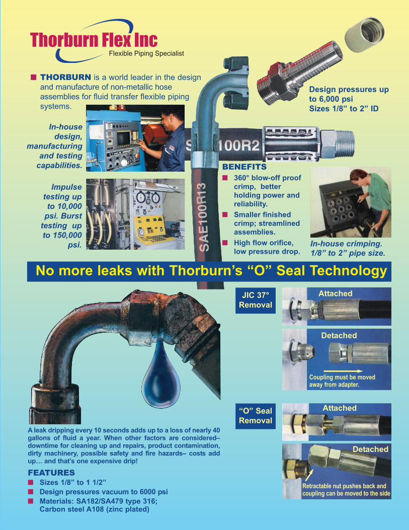
■ THORBURN is a world leader in the design
and manufacture of non-metallic hose
assemblies for fluid transfer flexible piping
systems.
FEATURES■ Sizes 1/8” to 1 1/2”
■ Design pressures vacuum to 6000 psi
■ Materials: SA182/SA479 type 316; Carbon steel A108 (zinc plated)
A leak dripping every 10 seconds adds up to a loss of nearly 40gallons of fluid a year. When other factors are considered–downtime for cleaning up and repairs, product contamination,dirty machinery, possible safety and fire hazards– costs addup… and that’s one expensive drip!
In-housedesign,
manufacturingand testing
capabilities.
In-house crimping.1/8” to 2” pipe size.
Impulsetesting upto 10,000
psi. Bursttesting upto 150,000
psi.
No more leaks with Thorburn’s “O” Seal Technology
JIC 37°
Removal
“O” Seal
Removal
Attached
Attached
Coupling must be movedaway from adapter.
Retractable nut pushes back andcoupling can be moved to the side
Detached
Detached
Design pressures up
to 6,000 psi
Sizes 1/8” to 2” ID
BENEFITS■ 360° blow-off proof
crimp, better
holding power and
reliability.
■ Smaller finished
crimp; streamlined
assemblies.
■ High flow orifice,
low pressure drop.
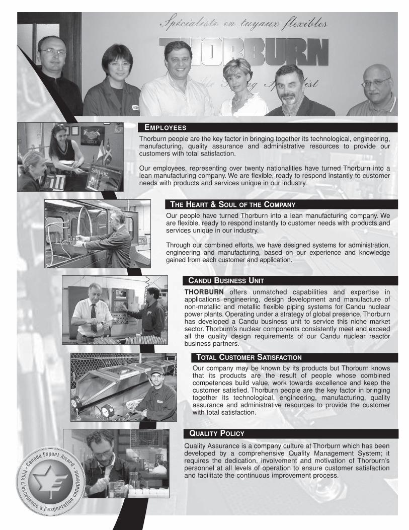
CANDU BUSINESS UNIT
QUALITY POLICY
TOTAL CUSTOMER SATISFACTION
EMPLOYEES
THE HEART & SOUL OF THE COMPANY
Quality Assurance is a company culture at Thorburn which has beendeveloped by a comprehensive Quality Management System; itrequires the dedication, involvement and motivation of Thorburn’spersonnel at all levels of operation to ensure customer satisfactionand facilitate the continuous improvement process.
Our company may be known by its products but Thorburn knowsthat its products are the result of people whose combined competences build value, work towards excellence and keep thecustomer satisfied. Thorburn people are the key factor in bringingtogether its technological, engineering, manufacturing, qualityassurance and administrative resources to provide the customerwith total satisfaction.
THORBURN offers unmatched capabilities and expertise in applications engineering, design development and manufacture ofnon-metallic and metallic flexible piping systems for Candu nuclearpower plants. Operating under a strategy of global presence, Thorburnhas developed a Candu business unit to service this niche market sector. Thorburn’s nuclear components consistently meet and exceedall the quality design requirements of our Candu nuclear reactor business partners.
Our people have turned Thorburn into a lean manufacturing company. Weare flexible, ready to respond instantly to customer needs with products andservices unique in our industry.
Through our combined efforts, we have designed systems for administration,engineering and manufacturing, based on our experience and knowledgegained from each customer and application.
Thorburn people are the key factor in bringing together its technological, engineering,manufacturing, quality assurance and administrative resources to provide our customers with total satisfaction.
Our employees, representing over twenty nationalities have turned Thorburn into alean manufacturing company. We are flexible, ready to respond instantly to customerneeds with products and services unique in our industry.
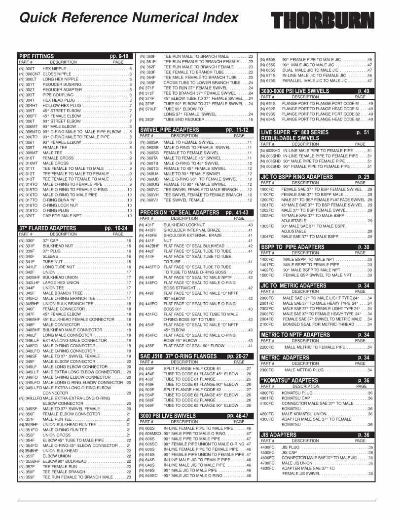
Quick Reference Numerical Index
������������ � � ��PART # DESCRIPTION PAGE
(N) 300T HEX NIPPLE . . . . . . . . . . . . . . . . . . . . . . . . . . . . .6(N) 300CNT CLOSE NIPPLE . . . . . . . . . . . . . . . . . . . . . . . . . .6(N) 300LT LONG HEX NIPPLE . . . . . . . . . . . . . . . . . . . . . . .6(N) 301T REDUCER BUSHING . . . . . . . . . . . . . . . . . . . . . .6(N) 302T REDUCER ADAPTER . . . . . . . . . . . . . . . . . . . . .6(N) 303T PIPE COUPLING . . . . . . . . . . . . . . . . . . . . . . . . .8(N) 304T HEX HEAD PLUG . . . . . . . . . . . . . . . . . . . . . . . .8(N) 304HT HOLLOW HEX PLUG . . . . . . . . . . . . . . . . . . . . . .7(N) 305T 45° STREET ELBOW . . . . . . . . . . . . . . . . . . . . . .7(N) 305FT 45° FEMALE ELBOW . . . . . . . . . . . . . . . . . . . . . .7(N) 306T 90° STREET ELBOW . . . . . . . . . . . . . . . . . . . . . .7(N) 306MT 90° MALE ELBOW . . . . . . . . . . . . . . . . . . . . . . . .8(N) 306MTO 90° O-RING MALE TO MALE PIPE ELBOW . . .8(N) 306TO 90° O-RING MALE TO FEMALE PIPE . . . . . . . . .8(N) 308T 90° FEMALE ELBOW . . . . . . . . . . . . . . . . . . . . . 8(N) 309T FEMALE TEE . . . . . . . . . . . . . . . . . . . . . . . . . . . .8(N) 309MT MALE TEE . . . . . . . . . . . . . . . . . . . . . . . . . . . . . .8(N) 310T FEMALE CROSS . . . . . . . . . . . . . . . . . . . . . . . . .9(N) 310MT MALE CROSS . . . . . . . . . . . . . . . . . . . . . . . . . . .9(N) 311T TEE FEMALE TO MALE TO MALE . . . . . . . . . . .9(N) 312T TEE FEMALE TO MALE TO FEMALE . . . . . . . . .9(N) 313T TEE FEMALE TO FEMALE TO MALE . . . . . . . . .9(N) 314TO MALE O-RING TO FEMALE PIPE . . . . . . . . . . . .9(N) 315TO MALE O-RING TO FEMALE O-RING . . . . . . . . .10(N) 316TO MALE O-RING TO MALE PIPE . . . . . . . . . . . . .10(N) 317TO O-RING BUNA “N” . . . . . . . . . . . . . . . . . . . . . . .10(N) 318TO O-RING LOCK NUT . . . . . . . . . . . . . . . . . . . . . .10(N) 319TO O-RING PLUG . . . . . . . . . . . . . . . . . . . . . . . . . .10(N) 320T CAP FOR MALE NPT . . . . . . . . . . . . . . . . . . . . .10
������������������ � �� ��PART # DESCRIPTION PAGE
(N) 330F 37° CAP . . . . . . . . . . . . . . . . . . . . . . . . . . . . . . .16(N) 331F BULKHEAD NUT . . . . . . . . . . . . . . . . . . . . . . . .16(N) 339F 37° PLUG . . . . . . . . . . . . . . . . . . . . . . . . . . . . . .16(N) 340F SLEEVE . . . . . . . . . . . . . . . . . . . . . . . . . . . . . . .16(N) 341F TUBE NUT . . . . . . . . . . . . . . . . . . . . . . . . . . . . .16(N) 341LF LONG TUBE NUT . . . . . . . . . . . . . . . . . . . . . . .16(N) 342F UNION . . . . . . . . . . . . . . . . . . . . . . . . . . . . . . . .17(N) 342BHF BULKHEAD UNION . . . . . . . . . . . . . . . . . . . . . .17(N) 342LHF LARGE HEX UNION . . . . . . . . . . . . . . . . . . . . .17(N) 344F UNION TEE . . . . . . . . . . . . . . . . . . . . . . . . . . . .17(N) 345F MALE BRANCH TREE . . . . . . . . . . . . . . . . . . . .17(N) 345FO MALE O-RING BRANCH TEE . . . . . . . . . . . . . .17(N) 345BHF UNION BULK BRANCH TEE . . . . . . . . . . . . . . .18(N) 346F FEMALE CONNECTOR . . . . . . . . . . . . . . . . . . .18(N) 347F 45° FEMALE ELBOW . . . . . . . . . . . . . . . . . . . .18(N) 346BHF 45° BULKHEAD FEMALE CONNECTOR . . . . .18(N) 348F MALE CONNECTOR . . . . . . . . . . . . . . . . . . . . .18(N) 348BHF BULKHEAD MALE CONNECTOR . . . . . . . . . . .19(N) 348LF LONG MALE CONNECTOR . . . . . . . . . . . . . . .19(N) 348LLF EXTRA-LONG MALE CONNECTOR . . . . . . . . .19(N) 348FO MALE O-RING CONNECTOR . . . . . . . . . . . . . .19(N) 348LFO MALE O-RING CONNECTOR . . . . . . . . . . . . . .19(N) 348SF MALE TO 37° SWIVEL FEMALE . . . . . . . . . . . .19(N) 349F MALE ELBOW CONNECTOR . . . . . . . . . . . . . .20(N) 349LF MALE LONG ELBOW CONNECTOR . . . . . . . .20(N) 349LLF MALE EXTRA-LONG ELBOW CONNECTOR . . .20(N) 349FO MALE O-RING ELBOW CONNECTOR . . . . . . .20(N) 349LFO MALE LONG O-RING ELBOW CONNECTOR .20(N) 349LLFO MALE EXTRA-LONG O-RING ELBOW
CONNECTOR . . . . . . . . . . . . . . . . . . . . . . . . . .20(N) 349LLLFO MALE EXTRA-EXTRA-LONG O-RING
ELBOW CONNECTOR . . . . . . . . . . . . . . . . . . .20(N) 349SF MALE TO 37° SWIVEL FEMALE . . . . . . . . . . . .20(N) 350F FEMALE ELBOW CONNECTOR . . . . . . . . . . . .21(N) 351F MALE RUN TEE . . . . . . . . . . . . . . . . . . . . . . . . .21(N) 351BHF UNION BULKHEAD RUN TEE . . . . . . . . . . . . .21(N) 351FO MALE O-RING RUN TEE . . . . . . . . . . . . . . . . . .21(N) 352F UNION CROSS . . . . . . . . . . . . . . . . . . . . . . . . .21(N) 354F ELBOW 45° TUBE TO MALE PIPE . . . . . . . . . .22(N) 354FO MALE O-RING 45° ELBOW CONNECTOR . . . .21(N) 354BHF UNION BULKHEAD . . . . . . . . . . . . . . . . . . . . . .22(N) 355F ELBOW UNION . . . . . . . . . . . . . . . . . . . . . . . . .22(N) 355BHF ELBOW 90° BULKHEAD . . . . . . . . . . . . . . . . . .22 (N) 357F TEE FEMALE RUN . . . . . . . . . . . . . . . . . . . . . .22(N) 358F TEE FEMALE BRANCH . . . . . . . . . . . . . . . . . .22(N) 359F TEE RUN FEMALE TO BRANCH MALE . . . . . .23
(N) 360F TEE RUN MALE TO BRANCH MALE . . . . . . . .23(N) 361F TEE RUN FEMALE TO BRANCH FEMALE . . . .23(N) 362F TEE RUN MALE TO BRANCH FEMALE . . . . . .23(N) 363F TEE FEMALE TO BRANCH TUBE . . . . . . . . . . .23(N) 364F TEE MALE. FEMALE TO BRANCH TUBE . . . . .23(N) 365F CROSS TUBE TO LOWER BRANCH TUBE . . .24
(N) 371F TEE TO RUN 37° FEMALE SWIVEL . . . . . . . . .24(N) 372F TEE TO BRANCH 37° FEMALE SWIVEL . . . . .24(N) 374F 45° ELBOW TUBE TO 37° FEMALE SWIVEL . .24(N) 379F TUBE 90° ELBOW TO 37° FEMALE SWIVEL . .24(N) 379LF TUBE 90° ELBOW TO
LONG 37° FEMALE SWIVEL . . . . . . . . . . . . . .24(N) 383F TUBE END REDUCER . . . . . . . . . . . . . . . . . . . .16
����� ������������ � �� ���PART # DESCRIPTION PAGE
(N) 360SA MALE TO FEMALE SWIVEL . . . . . . . . . . . . . . .11(N) 360SB MALE O-RING TO FEMALE SWIVEL . . . . . . .11(N) 360SG FEMALE TO FEMALE SWIVEL . . . . . . . . . . . . .11(N) 360TA MALE TO FEMALE 45° SWIVEL . . . . . . . . . . . .11(N) 360TB MALE O-RING TO 45° SWIVEL . . . . . . . . . . . .12(N) 360TG FEMALE TO 45° FEMALE SWIVEL . . . . . . . . .12(N) 360UA MALE TO 90° FEMALE SWIVEL . . . . . . . . . . . .12(N) 360UB MALE O-RING 90° TO FEMALE SWIVEL . . . .12(N) 360UG FEMALE TO 90° FEMALE SWIVEL . . . . . . . . .12(N) 360VC TEE SWIVEL FEMALE TO MALE BRANCH . . . .12(N) 360VH TEE SWIVEL FEMALE TO FEMALE BRANCH . .12(N) 360VJ TEE SWIVEL FEMALE . . . . . . . . . . . . . . . . . . .12
���������������� ������� � �� ��PART # DESCRIPTION PAGE
(N) 431F BULKHEAD LOCKNUT . . . . . . . . . . . . . . . . . . .43(N) 440FI SHOULDER INTERNAL BRAZE . . . . . . . . . . . .41(N) 440FE SHOULDER EXTERNAL BRAZE . . . . . . . . . . . .41(N) 441F NUT . . . . . . . . . . . . . . . . . . . . . . . . . . . . . . . . . .41(N) 442BHF FLAT FACE “O” SEAL BULKHEAD . . . . . . . . . .42(N) 442F FLAT FACE “O” SEAL TUBE TO TUBE . . . . . . .41(N) 444F FLAT FACE “O” SEAL TUBE TO TUBE
TO TUBE . . . . . . . . . . . . . . . . . . . . . . . . . . . . . .41(N) 445FFO FLAT FACE “O” SEAL TUBE TO TUBE
TO TUBE TO MALE O-RING BOSS . . . . . . . . .42(N) 448F FLAT FACE “O” SEAL TO MALE NPTF . . . . . . .42(N) 448FO FLAT FACE “O” SEAL TO MALE O-RING
BOSS STRAIGHT . . . . . . . . . . . . . . . . . . . . . . . .42(N) 449F FLAT FACE “O” SEAL TO MALE “O” NPTF
90° ELBOW . . . . . . . . . . . . . . . . . . . . . . . . . . . .42(N) 449FO FLAT FACE “O” SEAL TO MALE O-RING
BOSS 90° . . . . . . . . . . . . . . . . . . . . . . . . . . . . . .43(N) 451FO FLAT FACE “O” SEAL TO TUBE TO MALE
O-RING BOSS 90° TO TUBE . . . . . . . . . . . . . . .43(N) 454F FLAT FACE “O” SEAL TO MALE “O” NPTF
45° ELBOW . . . . . . . . . . . . . . . . . . . . . . . . . . . .43(N) 454FO FLAT FACE “O” SEAL TO MALE O-RING
BOSS 45° ELBOW . . . . . . . . . . . . . . . . . . . . . . .43(N) 455F FLAT FACE “O” SEAL 90° ELBOW . . . . . . . . . .41
���� �!������� ����������� � �� ��PART # DESCRIPTION PAGE
(N) 400F SPLIT FLANGE HALF CODE 61 . . . . . . . . . . .27(N) 454F TUBE TO CODE 61 FLANGE 45° ELBOW . . .26(N) 468F TUBE TO CODE 61 FLANGE . . . . . . . . . . . . . .26(N) 469F TUBE TO CODE 61 FLANGE 90° ELBOW . . .26(N) 500F SPLIT FLANGE HALF CODE 62 . . . . . . . . . . .27(N) 554F TUBE TO CODE 62 FLANGE 45° ELBOW . . .26(N) 568F TUBE TO CODE 62 FLANGE . . . . . . . . . . . . . .26(N) 569F TUBE TO CODE 62 FLANGE 90° ELBOW . . .26
������������������ � �� ��PART # DESCRIPTION PAGE
(N) 602S IN-LINE FEMALE PIPE TO MALE PIPE . . . . . .46(N) 606MSO 90° MALE PIPE TO MALE O-RING . . . . . . . . .47(N) 606S 90° MALE PIPE TO MALE PIPE . . . . . . . . . . . .47(N) 606SO 90° FEMALE PIPE UNION TO MALE O-RING .47(N) 608S IN-LINE FEMALE PIPE TO FEMALE PIPE . . .46(N) 618S 90° FEMALE PIPE UNION TO FEMALE PIPE .47(N) 646S IN-LINE MALE JIC TO FEMALE PIPE . . . . . . .46(N) 648S IN-LINE MALE JIC TO MALE PIPE . . . . . . . . .46(N) 649S 90° MALE JIC TO MALE PIPE . . . . . . . . . . . . .46(N) 649SO 90° MALE JIC TO MALE O-RING . . . . . . . . . . .46
(N) 650S 90° FEMALE PIPE TO MALE JIC . . . . . . . . . . . .46(N) 655S 90° MALE JIC TO MALE JIC . . . . . . . . . . . . . . .47(N) 665S DUAL MALE JIC TO MALE JIC . . . . . . . . . . . . .47(N) 671S IN-LINE MALE JIC TO FEMALE JIC . . . . . . . . .46(N) 675S PARALLEL MALE JIC TO MALE JIC . . . . . . . . .47
���� ������������������ � �"PART # DESCRIPTION PAGE
(N) 691S FLANGE PORT TO FLANGE PORT CODE 61 . . . .49(N) 692S FLANGE PORT TO FLANGE HEAD CODE 61 . . . .49(N) 693S FLANGE PORT TO FLANGE PORT CODE 62 . . . .49(N) 694S FLANGE PORT TO FLANGE HEAD CODE 62 . . . .49
�����#�������!��������� � ����$#����$��������PART # DESCRIPTION PAGE
(N) 802SHD IN-LINE MALE PIPE TO FEMALE PIPE . . . . . .51(N) 803SHD IN-LINE FEMALE PIPE TO FEMALE PIPE . . . .51(N) 806SHD 90° MALE PIPE TO FEMALE PIPE . . . . . . . . . .51(N) 808SHD 90° FEMALE PIPE TO FEMALE PIPE . . . . . . . .51
�������$�� ������������ � �"PART # DESCRIPTION PAGE
1000FC FEMALE SAE 37° TO BSP FEMALE SWIVEL . .291100FC FEMALE SAE 37° TO BSPP MALE . . . . . . . . . . .291200FC MALE 37° TO BSP FEMALE FLAT FACE SWIVEL .291201FC 45°MALE SAE 37° TO BSP FEMALE SWIVEL . .291202FC MALE 37° TO BSP FEMALE SWIVEL . . . . . . . . .291203FC 45°MALE SAE 37° TO MALE BSPP . . . . . . . . . . . .
ADJUSTABLE . . . . . . . . . . . . . . . . . . . . . . . . . . .291303FC 90° MALE SAE 37° TO MALE BSPP
ADJUSTABLE . . . . . . . . . . . . . . . . . . . . . . . . . . .291304FC MALE SAE 37° TO MALE BSPP . . . . . . . . . . . . .29
$�� ���������������� � ��PART # DESCRIPTION PAGE
1400FC MALE BSPP TO MALE NPT . . . . . . . . . . . . . . .301401FC MALE BSPP TO FEMALE PIPE . . . . . . . . . . . .301402FC 90° MALE BSPP TO MALE NPT . . . . . . . . . . . .301500FC FEMALE BSP SWIVEL TO MALE NPT . . . . . . .30
��������%������������� � ��PART # DESCRIPTION PAGE
2000FC MALE SAE 37° TO MALE LIGHT TYPE 24° . . .342001FC MALE SAE 37° TO MALE HEAVY TYPE 24° . . . .342002FC MALE SAE 37° TO FEMALE LIGHT TYPE 24° . . .342003FC MALE SAE 37° TO FEMALE HEAVY TYPE 24° . .342004FC FEMALE SAE 37° SWIVEL TO METRIC MALE . .342100FC BONDED SEAL FOR METRIC THREAD . . . . . .34
%��������������������� � ��PART # DESCRIPTION PAGE
2200FC MALE METRIC TO FEMALE PIPE . . . . . . . . . .34
%�������������� � ��PART # DESCRIPTION PAGE
2300FC MALE METRIC PLUG . . . . . . . . . . . . . . . . . . . .34
�&�%��#��������� � ��PART # DESCRIPTION PAGE
4000FC KOMATSU PLUG . . . . . . . . . . . . . . . . . . . . . . . . .364001FC KOMATSU CAP . . . . . . . . . . . . . . . . . . . . . . . . . .364100FC CONNECTOR MALE SAE 37° TO MALE . . . . . . . .
KOMATSU . . . . . . . . . . . . . . . . . . . . . . . . . . . . . .364200FC MALE KOMATSU UNION . . . . . . . . . . . . . . . . . . .364300FC ADAPTER MALE SAE 37° TO FEMALE
KOMATSU . . . . . . . . . . . . . . . . . . . . . . . . . . . . . .36
���������� � ��PART # DESCRIPTION PAGE
4400FC JIS PLUG . . . . . . . . . . . . . . . . . . . . . . . . . . . . . . .364500FC JIS CAP . . . . . . . . . . . . . . . . . . . . . . . . . . . . . . . .364600FC CONNECTOR MALE SAE 37° TO MALE JIS . . . . . .364700FC MALE JIS UNION . . . . . . . . . . . . . . . . . . . . . . . . .364800FC ADAPTER MALE SAE 37° TO
FEMALE JIS SWIVEL . . . . . . . . . . . . . . . . . . . . . .36
3
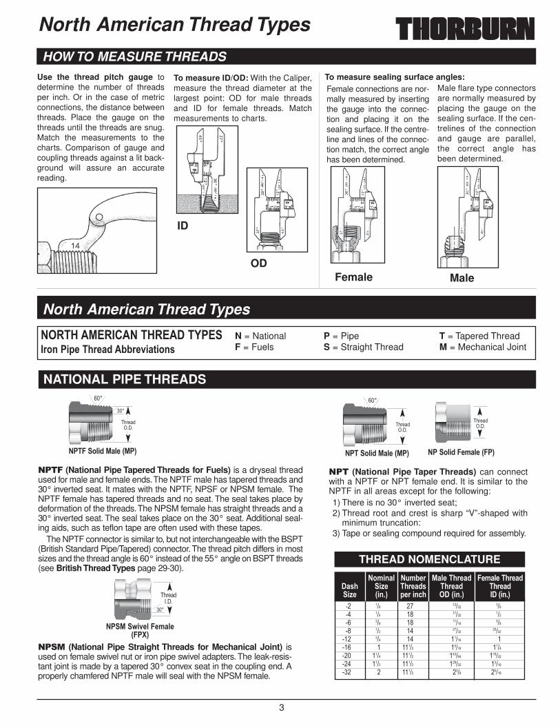
���� (National Pipe Tapered Threads for Fuels) is a dryseal threadused for male and female ends.The NPTF male has tapered threads and30° inverted seat. It mates with the NPTF, NPSF or NPSM female. TheNPTF female has tapered threads and no seat. The seal takes place bydeformation of the threads.The NPSM female has straight threads and a30° inverted seat. The seal takes place on the 30° seat. Additional seal-ing aids, such as teflon tape are often used with these tapes.
The NPTF connector is similar to, but not interchangeable with the BSPT(British Standard Pipe/Tapered) connector.The thread pitch differs in mostsizes and the thread angle is 60° instead of the 55° angle on BSPT threads(see British Thread Types page 29-30).
��� (National Pipe Taper Threads) can connectwith a NPTF or NPT female end. It is similar to theNPTF in all areas except for the following:1) There is no 30° inverted seat;2) Thread root and crest is sharp “V”-shaped with
minimum truncation:3) Tape or sealing compound required for assembly.
���� (National Pipe Straight Threads for Mechanical Joint) isused on female swivel nut or iron pipe swivel adapters.The leak-resis-tant joint is made by a tapered 30° convex seat in the coupling end. Aproperly chamfered NPTF male will seal with the NPSM female.
North American Thread Types
����'��%��������'������(���)*+��,-��.)-/0��11)-2,/3,*+4
N = National P = Pipe T = Tapered ThreadF = Fuels S = Straight Thread M = Mechanical Joint
���
���
������ �
�����*5,0�%/5-�6%�7
���
������ �
����*5,0�%/5-�6%�7
������ �
�� *5,0��-8/5-�6��7
���
������ �
��%�9,2-5��-8/5-6��:7
�� ��� �� ����� ����� ��� �� ����� ����� ��� �� ����� ����� ���� �� ����� �������� ���� �� ����� ���� � ����� ����� ������� ���� ����� ������ ��������� ����� ����� ������ �������� � ����� ���� �����
THREAD NOMENCLATURE
NATIONAL PIPE THREADS
HOW TO MEASURE THREADS Use the thread pitch gauge todetermine the number of threadsper inch. Or in the case of metricconnections, the distance betweenthreads. Place the gauge on thethreads until the threads are snug.Match the measurements to thecharts. Comparison of gauge andcoupling threads against a lit back-ground will assure an accuratereading.
To measure ID/OD: With the Caliper,measure the thread diameter at thelargest point: OD for male threadsand ID for female threads. Matchmeasurements to charts.
Female connections are nor-mally measured by insertingthe gauge into the connec-tion and placing it on thesealing surface. If the centre-line and lines of the connec-tion match, the correct anglehas been determined.
Male flare type connectorsare normally measured byplacing the gauge on thesealing surface. If the cen-trelines of the connectionand gauge are parallel,the correct angle hasbeen determined.
ID
ODFemale Male
To measure sealing surface angles:
North American Thread Types
�-8/5-��.)-/0�.)-/0���6,+�7
%/5-��.)-/0�.)-/0���6,+�7
�;81-)�.)-/04-)�,+<.
�*8,+/5,=-6,+�7
�/4.,=-
4
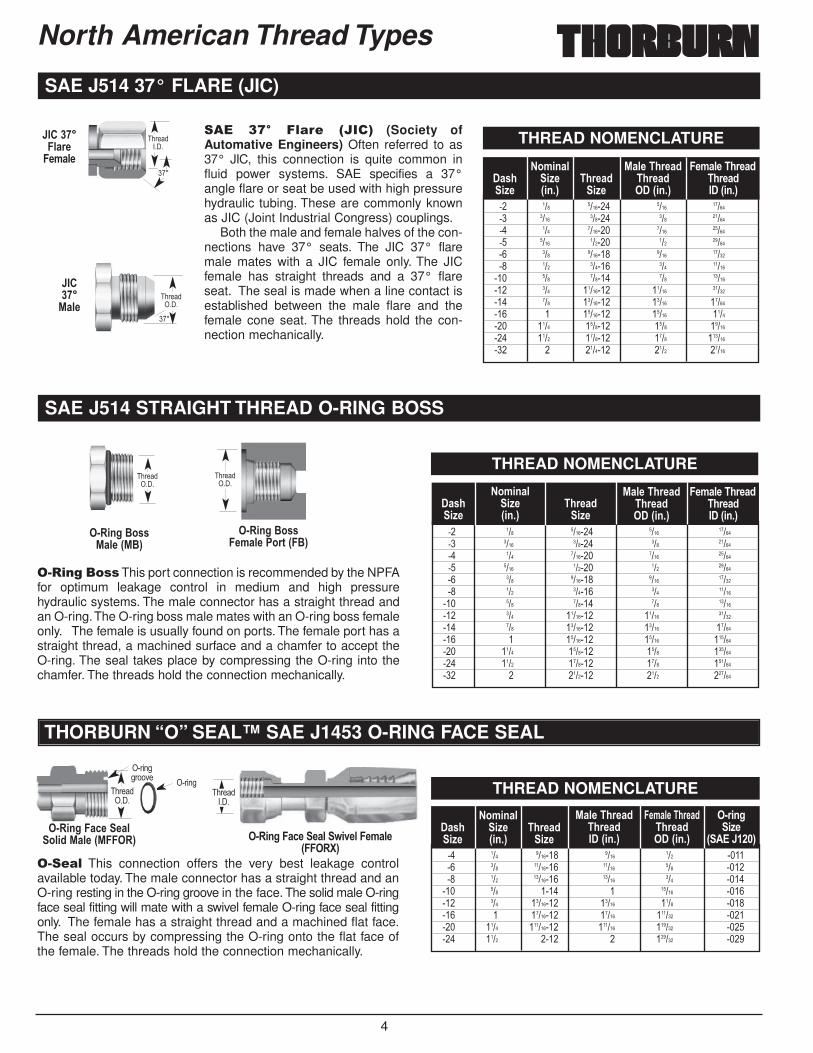
��� �� � ��� ����� (Society ofAutomative Engineers) Often referred to as37° JIC, this connection is quite common influid power systems. SAE specifies a 37°angle flare or seat be used with high pressurehydraulic tubing. These are commonly knownas JIC (Joint Industrial Congress) couplings.
Both the male and female halves of the con-nections have 37° seats. The JIC 37° flaremale mates with a JIC female only. The JICfemale has straight threads and a 37° flareseat. The seal is made when a line contact isestablished between the male flare and thefemale cone seat. The threads hold the con-nection mechanically.
������%/5-
���
������ �
��������5/)-�-8/5-
���
������ �
�� ��� ������� ���� ������� ���� ������ ��� ������� ��� ������� ���� ������� ���� ������ ��� ������� ��� ������� ����� ������� ���� ������ ��� ��������� ���� ������ ��� �������� ���� �������� ����� �������� ��� �������� ����� �������� � �������� ����� ������� ���� ������� ���� �������� ����� ������� ���� ��������� � ������� ���� �����
THREAD NOMENCLATURE
SAE J514 37° FLARE (JIC)
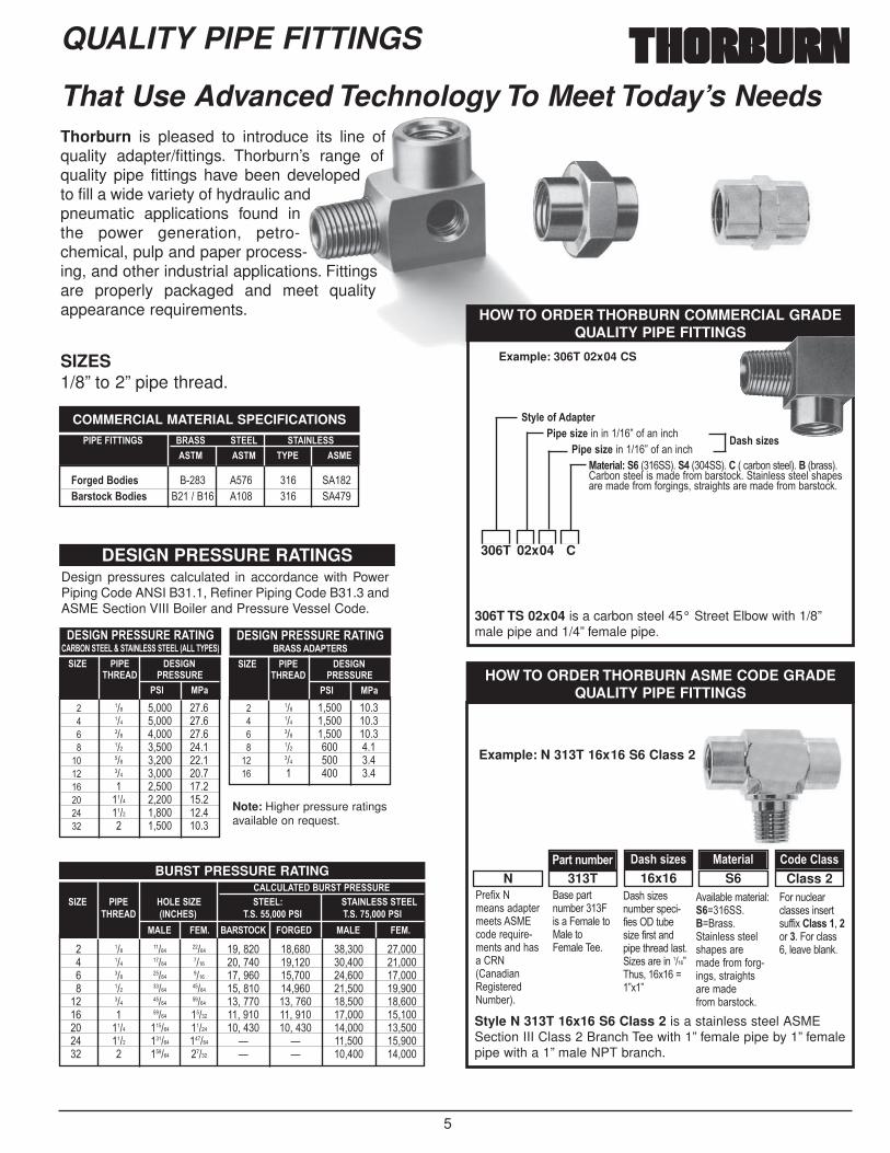
����������This port connection is recommended by the NPFAfor optimum leakage control in medium and high pressurehydraulic systems. The male connector has a straight thread andan O-ring.The O-ring boss male mates with an O-ring boss femaleonly. The female is usually found on ports. The female port has astraight thread, a machined surface and a chamfer to accept theO-ring. The seal takes place by compressing the O-ring into thechamfer. The threads hold the connection mechanically.
����� This connection offers the very best leakage controlavailable today. The male connector has a straight thread and anO-ring resting in the O-ring groove in the face. The solid male O-ringface seal fitting will mate with a swivel female O-ring face seal fittingonly. The female has a straight thread and a machined flat face.The seal occurs by compressing the O-ring onto the flat face ofthe female. The threads hold the connection mechanically.
������ �
������ �
� �,+>�$*44%/5-�6%$7
� �,+>�$*44�-8/5-��*)3�6�$7
������ �
������������
� �,+>��/<-�-/5*5,0�%/5-�6%����7
������������� �
� �,+>��/<-�-/5�9,2-5��-8/5-6����:7
�� ��� ������� ���� ������� ���� ������ ��� ������� ��� ������� ���� ������� ���� ������ ��� ������� ��� ������� ���� �������� ���� ������ ��� ��������� ���� ������ ��� �������� ���� �������� ����� �������� ��� �������� ����� �������� � �������� ����� ��������� ���� ������� ���� ��������� ����� ������� ���� ��������� � ������� ���� ������
�� ��� ������� ���� ���� ������ ��� �������� ����� ��� ������ ���� �������� ����� ��� ������� ���� ���� � ����� ������� ���� �������� ����� ���� ������� � �������� ����� ������ ������� ���� ��������� ������ ������ ������� ����� ���� � ������ ����
THREAD NOMENCLATURE
THREAD NOMENCLATURE
SAE J514 STRAIGHT THREAD O-RING BOSS
THORBURN “O” SEAL™ SAE J1453 O-RING FACE SEAL
North American Thread Types
�-8/5-��.)-/0�.)-/0���6,+�7
%/5-��.)-/0�.)-/0���6,+�7
�.)-/0,=-
�*8,+/5,=-6,+�7
�/4.,=-
�-8/5-��.)-/0�.)-/0���6,+�7
%/5-��.)-/0�.)-/0���6,+�7
�.)-/0,=-
�*8,+/5,=-6,+�7
�/4.,=-
�.)-/0,=-
�*8,+/5,=-6,+�7
�/4.,=-
� ),+>,=-
6�������7
�-8/5-��.)-/0�.)-/0���6,+�7
%/5-��.)-/0�.)-/0���6,+�7
5
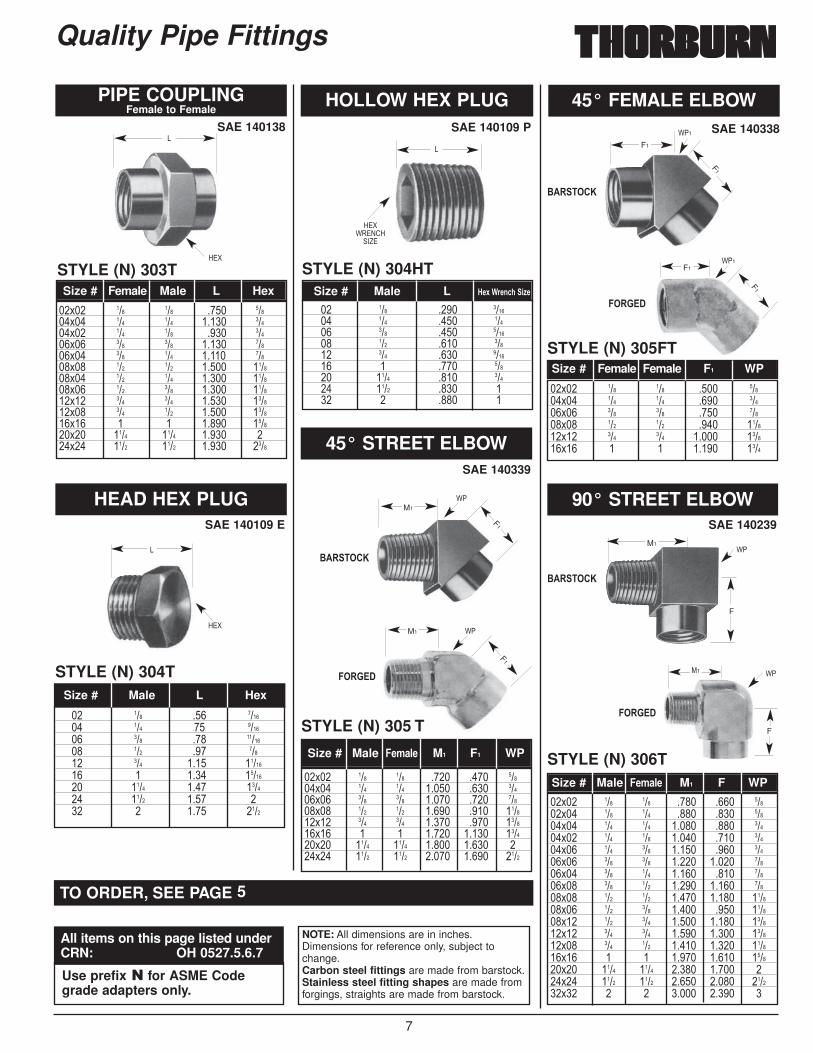
Thorburn is pleased to introduce its line ofquality adapter/fittings. Thorburn’s range ofquality pipe fittings have been developedto fill a wide variety of hydraulic andpneumatic applications found inthe power generation, petro-chemical, pulp and paper process-ing, and other industrial applications. Fittingsare properly packaged and meet qualityappearance requirements.
Style N 313T 16x16 S6 Class 2 is a stainless steel ASMESection III Class 2 Branch Tee with 1” female pipe by 1” femalepipe with a 1” male NPT branch.
That Use Advanced Technology To Meet Today’s Needs
COMMERCIAL MATERIAL SPECIFICATIONS
������������ $�� ���� ��������% ��% �(�� �%�
�*)>-0�$*0,-4 ����� ���� ��� ����$/)43*<?�$*0,-4 ��������� ���� ��� ����
���������#���������$����������
���������#������������$������� @������������ 6��� �(��7
� ��� �!��� ����� ��� �!��� ����� ��� �!��� ����� ��� �!��� ������ ��� �!��� ������ ��� �!��� ������ � �!��� ������ ���� �!��� ������ ���� �!��� ������ � �!��� ����
�A� ���� �������'���� ���#��
�� %�/� ��� �!��� ����� ��� �!��� ����� ��� �!��� ����� ��� ��� ����� ��� ��� ����� � ��� ���
�A� ���� �������'���� ���#��
�� %�/
QUALITY PIPE FITTINGS
SIZES1/8” to 2” pipe thread.
Note: Higher pressure ratingsavailable on request.
Example: N 313T 16x16 S6 Class 2
HOW TO ORDER THORBURN ASME CODE GRADEQUALITY PIPE FITTINGS
"��#�$�%&��'�()��&��)'�� *+,�����-.����&��)'����'�/0%1/���0���')���%.&2��3�
�'��(�)�.&2������4�'��4�&5��)�*5��)�4�&5������
'��'�6�'�.&2���'(�,��#��'�� �).2�'�6��#��')��(�(��)����5')� �6�'�����������7��.'!���$���8�7$�7
���525��&)���59�8��� �$8��''� )��5�''�')��5�'�(�'���&��#��&�#�������'!�')����)'���&��#��&�2�')�,:�
4����.,5��,5''�'���'��)'.##�$ �5/44��!��������4���,5''�!�5����25�:�
Class 2S616x16313TN�/)3�+;81-) �/4.�4,=-4 %/3-),/5 �*0-��5/44
BURST PRESSURE RATING
� ��� ����� ����� ��!���� ��!��� ��!��� ��!���� ��� ����� ���� ��!���� ��!��� ��!��� ��!���� ��� ����� ���� ��!���� ��!��� ��!��� ��!���� ��� ����� ����� ��!���� ��!��� ��!��� ��!����� ��� ����� ����� ��!���� ��!���� ��!��� ��!����� � ����� ����� ��!���� ��!���� ��!��� ��!����� ���� ������ ����� ��!���� ��!���� ��!��� ��!����� ���� ������ ������ ; ; ��!��� ��!����� � ������ ����� ; ; ��!��� ��!���
����#������$#������#���A� ���� '�����A� ����B �����������
�'���� 6���'�7 ���� C������ ����� C������%��� ��%� $�����& ������ %��� ��%�
DESIGN PRESSURE RATINGSDesign pressures calculated in accordance with PowerPiping Code ANSI B31.1, Refiner Piping Code B31.3 andASME Section VIII Boiler and Pressure Vessel Code. 306T TS 02x04 is a carbon steel 45° Street Elbow with 1/8”
male pipe and 1/4” female pipe.
HOW TO ORDER THORBURN COMMERCIAL GRADEQUALITY PIPE FITTINGS
3D5-�*E��0/3-)�,-�4,=- �� �������7��#�����,�
�,-�4,=- �������7��#�����,�%/3-),/5B � 1��� 3��� 1��� 3����1�,�2���')��53��$ 12�''3�/�2���')��5��'�&��#��&�2�')�,:�� )��5�''�')��5�'�(�'���&��#��&�#������'!�')����)'����&��#��&�2�')�,:�
Example: 306T 02x04 CS
�/4.�4,=-4
306T 02x04 C

6
Size # Female Male L Hex
Quality Pipe Fittings
HEX NIPPLE LONG HEX NIPPLE�.,4�,4�/�+*+ 43*<?�,3-8���*+3/<3��.*)1;)+�E*)�/2/,5/1,5,3D
ADAPTERFemale to Reduced Male Pipe Thread
SAE 140137
STYLE (N) 300T
��$�� ��� ��� ����� ������$�� ��� ��� ����� �����$�� ��� ��� ����� �����$�� ��� ��� ����� �����$�� ��� ��� ����� �����$�� ��� ��� ����� �����$�� ��� ��� ����� �����$�� ��� ��� ����� �����$�� ��� ��� ����� �����$�� ��� ��� ����� ������$�� ��� ��� ����� ������$�� � � ����� ������$�� � ��� ����� ������$�� ���� ���� ����� ������$�� ���� � ����� ������$�� ���� ���� ����� ���$�� � � ����� ����
�� ��� ��� ����� ��� ���� ����� ��� ���� ����� ��� ���� ����� ��� ���� ����� � ���� ���
��$��� ��� ��� ������$� ��� � ������$��� ��� ��� ������$� ��� � ������$� ��� � �����$��� ��� ��� �����$� ��� � �����$� ��� � �����$� ��� � �����$� ��� � �����$��� ��� ��� �����$� ��� � �����$� ��� � �����$� ��� � �����$� ��� � �����$��� ��� ��� �����$� ��� � �����$� ��� � �����$� ��� � �����$� ��� � ������$� ��� � ������$� ��� � ������$� � � ������$� � � ������$� ���� � ������$� ���� � ������$� ���� � ���$� ���� � ���$� � � ������$� � � ����
REDUCER BUSHINGMale to Reduced Female Pipe Thread
SAE 140140
SAE 140139
STYLE (N) 301T
STYLE (N) 302T
STYLE (N) 300LT
CLOSE NIPPLE
STYLE (N) 300CNT
Size # Male Male L Hex
��$�� ��� ��� ���� �����$�� ��� ��� ���� �����$�� ��� ��� ���� �����$�� ��� ��� ���� �����$�� ��� ��� ���� �����$�� ��� ��� ���� �����$�� ��� ��� ����� ������$�� ��� ��� ����� ������$�� ��� ��� ����� ������$�� � ��� ����� ������$�� � ��� ����� ������$�� � ��� ����� ������$�� � ��� ����� ������$�� ���� ��� ����� ������$�� ���� ��� ����� ������$�� ���� � ����� ������$�� ���� ��� ����� ���$�� ���� � ����� ���$�� ���� ���� ����� ���$�� � ���� ����� ������$�� � ���� ����� ����
��$�� ��� ��� ����� �����$�� ��� ��� ����� �����$�� ��� ��� ����� �����$�� ��� ��� ����� ������$�� ��� ��� ����� ������$�� ��� ��� ����� ������$�� ��� ��� ����� ������$�� ��� ��� ����� ������$�� ��� ��� ����� ������$�� ��� ��� ����� ������$�� � ��� ����� ������$�� � ��� ����� ������$�� ���� � ����� �
Size # Male Female L Hex
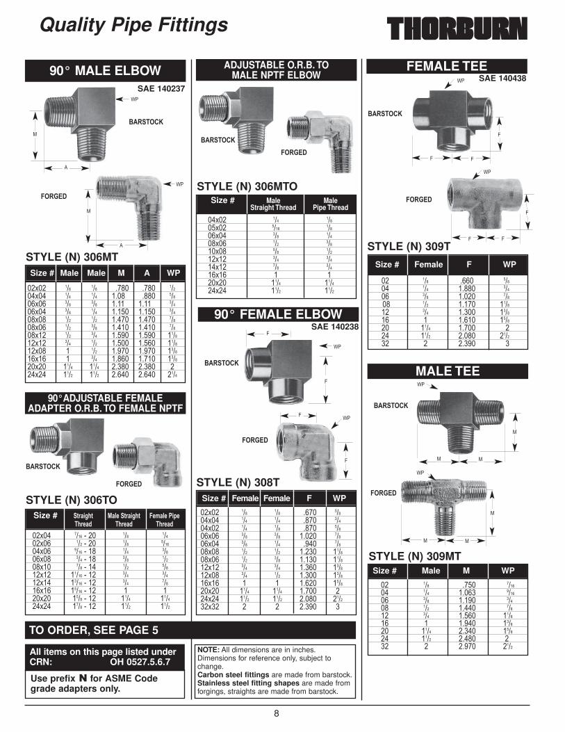
NOTE: All dimensions are in inches.Dimensions for reference only, subject tochange.Carbon steel fittings are made from barstock.Stainless steel fitting shapes are made fromforgings, straights are made from barstock.
TO ORDER, SEE PAGE 5
Size # %/5-��,-�,=- A ���%,+���-+,+>
Size # Male L Hex
<
=+>=+>
+
�
<
<
=+>
<
=+>
All items on this page listed underCRN: OH 0527.5.6.7
Use prefix � for ASME Codegrade adapters only.
7
Quality Pipe Fittings
�� ��� ��� ������ ��� ��� ������ ��� ��� ������� ��� ��� ����� ��� ���� ������� � ���� ������� ���� ���� ������ ���� ���� ��� � ���� ����
�� ��� ���� ������ ��� ���� ����� ��� ���� ������ ��� ���� ����� ��� ���� ������ � ���� ����� ���� ���� ����� ���� ���� ��� � ���� �
PIPE COUPLINGFemale to Female
SAE 140138
SAE 140109 E
STYLE (N) 303T
��$�� ��� ��� ���� �����$�� ��� ��� ����� �����$�� ��� ��� ���� �����$�� ��� ��� ����� �����$�� ��� ��� ����� �����$�� ��� ��� ����� ������$�� ��� ��� ����� ������$�� ��� ��� ����� ������$�� ��� ��� ����� ������$�� ��� ��� ����� ������$�� � � ����� ������$�� ���� ���� ����� ���$�� ���� ���� ����� ����
��$�� ��� ��� ���� �����$�� ��� ��� ���� �����$�� ��� ��� ���� �����$�� ��� ��� ���� ������$�� ��� ��� ����� ������$�� � � ����� ����
��$�� ��� ��� ���� ���� �����$�� ��� ��� ����� ���� �����$�� ��� ��� ����� ���� �����$�� ��� ��� ����� ���� ������$�� ��� ��� ����� ���� ������$�� � � ����� ����� ������$�� ���� ���� ����� ����� ���$�� ���� ���� ����� ����� ����
Size # Male �-8/5- M1 F1 WP
��$�� ��� ��� ���� ���� �����$�� ��� ��� ���� ���� �����$�� ��� ��� ����� ���� �����$�� ��� ��� ����� ���� �����$�� ��� ��� ����� ���� �����$�� ��� ��� ����� ����� �����$�� ��� ��� ����� ���� �����$�� ��� ��� ����� ����� �����$�� ��� ��� ����� ����� ������$�� ��� ��� ����� ���� ������$�� ��� ��� ����� ����� ������$�� ��� ��� ����� ����� ������$�� ��� ��� ����� ����� ������$�� � � ����� ����� ������$�� ���� ���� ����� ����� ���$�� ���� ���� ����� ����� ������$�� � � ����� ����� �
Size # Male �-8/5- M1 F WP
Size # Female Female F1 WP
Size # Male L '-F��)-+<.�,=-Size # Female Male L Hex
HEAD HEX PLUG
STYLE (N) 304T
SAE 140109 P
HOLLOW HEX PLUG
STYLE (N) 304HT
SAE 140339
45° STREET ELBOW
STYLE (N) 305 T
SAE 140239
90° STREET ELBOW
STYLE (N) 306T
SAE 140338
45° FEMALE ELBOW
STYLE (N) 305FT
Size # Male L Hex
?"
<
=+>
M1
F1
?"M1
F1
?"1F1
F1
?"1
F1
F1
?"
F
*1
?"M1
<
=+>
<
=+>?0+%/= �@+
F
������
$�����&
������
$�����&
������
$�����&
TO ORDER, SEE PAGE 5
NOTE: All dimensions are in inches.Dimensions for reference only, subject tochange.Carbon steel fittings are made from barstock.Stainless steel fitting shapes are made fromforgings, straights are made from barstock.
All items on this page listed underCRN: OH 0527.5.6.7
Use prefix � for ASME Codegrade adapters only.
8
Quality Pipe Fittings
SAE 140438FEMALE TEE
STYLE (N) 309T
MALE TEE
STYLE (N) 309MT
�� ��� ���� ����� ��� ����� ����� ��� ����� ����� ��� ����� ������ ��� ����� ������ � ����� ������ ���� ����� ��� ���� ����� ������ � ����� �
Size # Female F WP
�� ��� ���� ������ ��� ����� ������ ��� ����� ����� ��� ����� ����� ��� ����� ������ � ����� ������ ���� ����� ������ ���� ����� ��� � ����� ����
Size # Male M WP
?"
4
44
?"
*
**
?"
4
44
?"
*
**
��$�� ��� ��� ���� �����$�� ��� ��� ���� �����$�� ��� ��� ���� �����$�� ��� ��� ����� �����$�� ��� ��� ���� �����$�� ��� ��� ����� ������$�� ��� ��� ����� ������$�� ��� ��� ����� ������$�� ��� ��� ����� ������$�� � � ����� ������$�� ���� ���� ����� ���$�� ���� ���� ����� ������$�� � � ����� �
Size # Female Female F WP
SAE 14023890° FEMALE ELBOW
STYLE (N) 308T
?"
4
4
?"
4
4
Size # Male MaleStraight Thread Pipe Thread
��$�� ��� �����$�� ���� �����$�� ��� �����$�� ��� �����$�� ��� �����$�� ��� �����$�� ��� �����$�� � ���$�� ���� ������$�� ���� ����
STYLE (N) 306MTO
ADJUSTABLE O.R.B. TO MALE NPTF ELBOW
��$�� ���� ���� ��� �����$�� ��� ���� ��� ������$�� ���� ���� ��� �����$�� ��� ���� ��� �����$�� ��� ���� ��� �����$�� ����� ���� ��� �����$�� ����� ���� ��� �����$�� ����� ���� � ���$�� ���� ���� ���� ������$�� ���� ���� ���� ����
Size # 3)/,>.3� %/5-�3)/,>.3 �-8/5-��,-�.)-/0 �.)-/0 �.)-/0
STYLE (N) 306TO
90°ADJUSTABLE FEMALE ADAPTER O.R.B. TO FEMALE NPTF
��$�� ��� ��� ���� ���� �����$�� ��� ��� ���� ���� �����$�� ��� ��� ���� ���� �����$�� ��� ��� ����� ����� �����$�� ��� ��� ����� ����� �����$�� ��� ��� ����� ����� �����$�� ��� ��� ����� ����� ������$�� ��� ��� ����� ����� ������$�� � ��� ����� ����� ������$�� � ��� ����� ����� ������$�� ���� ���� ����� ����� ���$�� ���� ���� ����� ����� ����
Size # Male Male M A WP
SAE 140237
90° MALE ELBOW
STYLE (N) 306MT
?"
?"
*
�
*
�
������
$�����&
������$�����&
������
$�����&
������
$�����&
������
$�����&
������
$�����&
NOTE: All dimensions are in inches.Dimensions for reference only, subject tochange.Carbon steel fittings are made from barstock.Stainless steel fitting shapes are made fromforgings, straights are made from barstock.
TO ORDER, SEE PAGE 5
All items on this page listed underCRN: OH 0527.5.6.7
Use prefix � for ASME Codegrade adapters only.
9
Quality Pipe Fittings
SAE 140538SAE 140424
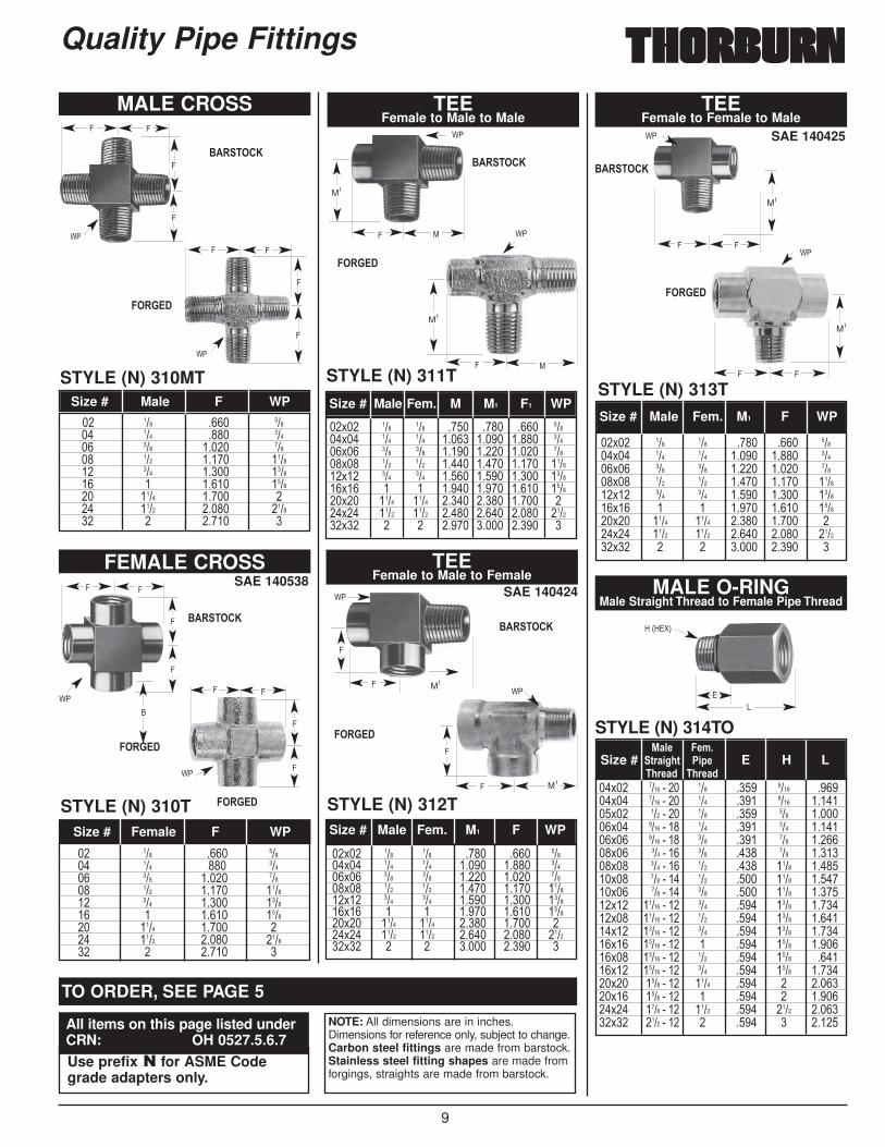
FEMALE CROSS
STYLE (N) 310T
MALE CROSS
STYLE (N) 310MT
TEEFemale to Male to Male
TEEFemale to Male to Female
STYLE (N) 311T
STYLE (N) 312T
SAE 140425
TEEFemale to Female to Male
STYLE (N) 313T
MALE O-RINGMale Straight Thread to Female Pipe Thread
STYLE (N) 314TO
�� ��� ���� ����� ��� ���� ����� ��� ����� ����� ��� ����� ������ ��� ����� ������ � ����� ������ ���� ����� ��� ���� ����� ������ � ����� �
Size # Male F WP
�� ��� ���� ����� ��� ���� ����� ��� ����� ����� ��� ����� ������ ��� ����� ������ � ����� ������ ���� ����� ��� ���� ����� ������ � ����� �
Size # Female F WP
��$�� ��� ��� ���� ���� ���� �����$�� ��� ��� ����� ����� ����� �����$�� ��� ��� ����� ����� ����� �����$�� ��� ��� ����� ����� ����� ������$�� ��� ��� ����� ����� ����� ������$�� � � ����� ����� ����� ������$�� ���� ���� ����� ����� ����� ���$�� ���� ���� ����� ����� ����� ������$�� � � ����� ����� ����� �
Size # Male Fem. M M1 F1 WP
��$�� ��� ��� ���� ���� �����$�� ��� ��� ����� ����� �����$�� ��� ��� ����� ����� �����$�� ��� ��� ����� ����� ������$�� ��� ��� ����� ����� ������$�� � � ����� ����� ������$�� ���� ���� ����� ����� ���$�� ���� ���� ����� ����� ������$�� � � ����� ����� �
Size # Male Fem. M1 F WP
��$�� ��� ��� ���� ���� �����$�� ��� ��� ����� ����� �����$�� ��� ��� ����� ����� �����$�� ��� ��� ����� ����� ������$�� ��� ��� ����� ����� ������$�� � � ����� ����� ������$�� ���� ���� ����� ����� ���$�� ���� ���� ����� ����� ������$�� � � ����� ����� �
Size # Male Fem. M1 F WP
��$�� ���� ���� ��� ���� ���� ������$�� ���� ���� ��� ���� ���� �������$�� ��� ���� ��� ���� ��� �������$�� ���� ���� ��� ���� ��� �������$�� ���� ���� ��� ���� ��� �������$�� ��� ���� ��� ���� ��� �������$�� ��� ���� ��� ���� ���� �������$�� ��� ���� ��� ���� ���� �������$�� ��� ���� ��� ���� ���� �������$�� ����� ���� ��� ���� ���� �������$�� ����� ���� ��� ���� ���� �������$�� ����� ���� ��� ���� ���� �������$�� ����� ���� � ���� ���� �������$�� ����� ���� ��� ���� ���� ������$�� ����� ���� ��� ���� ���� �������$�� ���� ���� ���� ���� � �������$�� ���� ���� � ���� � �������$�� ���� ���� ���� ���� ���� �������$�� ���� ���� � ���� � �����
%/5- �-8�Size # 3)/,>.3 �,- E H L
�.)-/0� �.)-/0
?"
44
?"
?"
4
4
44
4
?"
=�1=+>3
<+
?"
4
4
44
?"
M1
M1
*4
?"
4
4
44
4
4
44
4
4
?"
M1
4
?"
M1
*4
M1
?"
44
M1
������
$�����&
������
$�����&
������
$�����&
������
$�����&
������
$�����&
NOTE: All dimensions are in inches.Dimensions for reference only, subject to change.Carbon steel fittings are made from barstock.Stainless steel fitting shapes are made fromforgings, straights are made from barstock.
TO ORDER, SEE PAGE 5
All items on this page listed underCRN: OH 0527.5.6.7Use prefix � for ASME Codegrade adapters only.
�
������

10
%/5- �-8�Size # 3)/,>.3 3)/,>.3 H L
�.)-/0� �.)-/0
�� ����� ����� ����� ����� ��� ������ ������ ��
Quality Pipe Fittings
SAE 09109 A
O-RINGMale Straight Thread to Male Pipe Thread
STYLE (N) 316TO
THREAD STRAIGHTO-RING PLUG
STYLE (N) 319TO
MALE O-RING TOFEMALE O-RING
STRAIGHT THREADO-RING LOCKNUT
STYLE (N) 315TO
STYLE(N) 318TO
O-RINGMade of BUNA-N 90
STYLE (N) 317TO
��$�� ���� ���� ��� ���� ���� ���� ������$�� ��� ���� ��� ���� ���� ��� ������$�� ���� ���� ��� ���� ���� ����� �������$�� ���� ���� ��� ���� ���� ��� �������$�� ��� ���� ��� ���� ���� ��� �������$�� ��� ���� ��� ���� ���� � �������$�� ��� ���� ��� ���� ���� � �������$�� ����� ���� ��� ���� ���� ���� �������$�� ����� ���� ��� ���� ���� ���� �������$�� ����� ���� � ���� ���� ���� �������$�� ���� ���� ���� ���� ���� ���� �������$�� ���� ���� ���� ����� ���� ���� �������$�� ���� ���� � ����� ���� ���� �����
�� ���� ���� ���� ������ ��� ���� ���� ������ ���� ���� ���� ������ ��� ���� ���� ������ ���� ���� ���� ������ ��� ���� ���� ������ ��� ���� ���� ������ ����� ���� ���� ������ ����� ���� ����� ������ ����� ���� ����� ������ ���� ���� ����� ������ ���� ���� ����� ������ ���� ���� ����� ����
%/5- %/5-Size # 3)/,>.3 �,- D E H L
�.)-/0� �.)-/0
�� ���� ���� ���� ���� ������ ��� ���� ���� ��� ������ ���� ���� ���� ����� ������ ��� ���� ���� ��� ������ ��� ���� ���� � ������ ����� ���� ���� ���� ������� ����� ���� ���� ���� ������� ����� ���� ���� ���� ������� ���� ���� ���� ���� ������� ���� ���� ���� ���� �����
Size # 3)/,>.3 C H L�.)-/0
��$�� ��� ���� ���� ���� ��� �������$�� ����� ���� ��� ���� ���� �������$�� ����� ���� ����� ���� ���� �������$�� ����� ���� ��� ���� ���� �������$�� ����� ���� ����� ���� ���� �������$�� ���� ���� ����� ���� ���� �������$�� ���� ���� ����� ���� ���� �������$�� ���� ���� ���� ���� ���� �����
�� ���� ���� ���� ������ ��� ���� ��� ������ ���� ���� ����� ������ ��� ���� ��� ������ ��� ���� � ������ ����� ���� ���� ������ ����� ���� ���� ������ ����� ���� ���� ������ ���� ���� ���� ������ ���� ���� ���� ������ ���� ���� ���� ����
Size # 3)/,>.3 H L�.)-/0
Size # �*)3�3)/,>.3 � �,+>����� � �,+>���.)-/0
<
=�1=+>3
/
=�1=+>3
CAP FOR MALE NPT
STYLE (N) 320TSize # ��%�������
=�1=+>3
+
<
H(Hex)
<
�
NOTE: All dimensions are in inches.Dimensions for reference only, subject to change.Carbon steel fittings are made from barstock.Stainless steel fitting shapes are made fromforgings, straights are made from barstock.
Thorburn Pipe Fittings that require O-rings are shipped with the O-rings installed. If itbecomes necessary to replace the O-ring, lubricate the replacement O-ring with a lightcoating of oil or petroleum jelly. Stretch the O-ring and carefully roll it over the fittingthreads into the O-ring groove, being careful not to nick or cut the O-ring on thethreads. A damaged O-ring could lead to leakage. Once the O-ring has been installed,final assembly to an SAE straight thread port can be accomplished. Properly installedThorburn O-rings provide a dependable seal.
Thorburn standard O-rings are made of Buna-N material standard.Other materials available on special order.
TO ORDER, SEE PAGE 5O-RING REPLACEMENT
All items on this page listed underCRN: OH 0527.5.6.7
Use prefix � for ASME Codegrade adapters only.
11
� ����$���%�������������%������%
SAE 140330
STYLE (N) 360TA
��$�� ��� ��� �����$�� ��� ��� �������$�� ��� ��� �������$�� ��� ��� �������$�� ��� ��� ���$�� ��� ��� �������$�� ��� ��� �������$�� ��� ��� �������$�� ��� ��� �������$�� ��� ��� �������$�� ��� ��� ��������$�� ��� ��� ��������$�� ��� � ��������$�� � ��� ������$�� � � ������$�� ���� � ������$�� ���� ���� ������$�� ���� ���� ��������$�� � � �
Size # %/5-����� �-8/5-���% A�.)-/0��� �.)-/0���
T2
T1
A
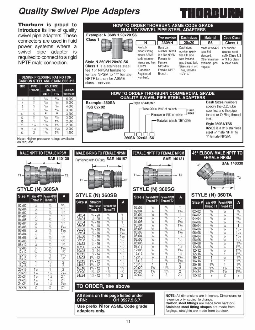
��%��������������%������%SAE 140131
STYLE (N) 360SG
Quality Swivel Pipe Adapters
��$�� ��� ��� �����$�� ��� ��� �������$�� ��� ��� ���$�� ��� ��� ������$�� ��� ��� �������$�� ��� ��� �������$�� ��� ��� ������$�� ��� ��� �������$�� ��� ��� ������$�� ��� ��� ������$�� ��� ��� ������$�� ��� ��� ������$�� ��� ��� �������$�� ��� ��� ������$�� ��� � �������$�� � ��� �������$�� � � ���$�� ���� ���� ���$�� ���� ���� ���$�� � � ����
Size # �-8/5-����� �-8/5-���% A�.)-/0��� �.)-/0���
%��������������%������%SAE 140130
STYLE (N) 360SA
%����� ����������%������%SAE 140157
STYLE (N) 360SB
��$�� ��� ��� �������$�� ��� ��� ������$�� ��� ��� ������$�� ��� ��� ������$�� ��� ��� ������$�� ��� ��� ������$�� ��� ��� �������$�� ��� ��� �������$�� ��� ��� ������$�� ��� ��� ������$�� ��� ��� ������$�� ��� ��� ������$�� ��� ��� �������$�� ��� ��� ������$�� ��� � ��������$�� � ��� ������$�� � ���� ���$�� � � ���$�� ���� � ���$�� ���� ���� �������$�� ���� ���� ������$�� ���� ���� ������$�� ���� ���� �������$�� � � ����
Size # %/5-����� �-8/5-���% A�.)-/0��� �.)-/0���
��$�� ���� ���� ��� ���$�� ��� ���� ��� ���$�� ���� ���� ��� ���$�� ���� ���� ��� ������$�� ���� ���� ��� �������$�� ��� ���� ��� �������$�� ��� ���� ��� �������$�� ��� ���� ��� ������$�� ��� ���� ��� ������$�� ��� ���� ��� ������$�� ��� ���� ��� ������$�� ��� ���� ��� ������$�� ����� ���� ��� ������$�� ����� ���� ��� ������$�� ����� ���� ��� ������$�� ����� ���� � ������$�� ���� ���� ���� ������$�� ���� ���� ���� �
4.���'���A�)����0���
Size # Straight A%/5-��.)-/0 �-8/5-���%�.)-/0��� �.)-/0���
A
T1 T2 T1 T2
T1 T2
AA
HOW TO ORDER THORBURN COMMERCIAL GRADE QUALITY SWIVEL PIPE STEEL ADAPTERS
3D5-�*E��0/3-)�;1-�����������7��#�����,�
�,-�4,=- �������7��#�����,�%/3-),/5B 1')��53��B�7�1���3
Example: 360SATSS 02x02
HOW TO ORDER THORBURN ASME CODE GRADE QUALITY SWIVEL PIPE STEEL ADAPTERS
"��#�$�%&��'�#�))���&��)'�� *+,�����-.����&��)'����'�/0%1/���0���')���%.&2��3�
�'��(�)�.&2������C=�'������%" *4�&5���)�4�&5�%" *�)�4�&5���%"�4���,���
'��'�6�'�.&2���'(�,��#��'�� �).2�'�6��#��')��(�(��)����5')� �6�'�����������7���.'!���$���8����7$����7
*���#� ����)D(������')�����)����&)���5'��525��.(����-.�')�
4����.,5��,5''�'���'��)'.##�$ �5/44��!��������4���,5''�!�5����25�:�
Class 1S620x20360VHN�/)3�+;81-) �/4.�4,=-4 %/3-),/5 �*0-��5/44
�/4.4,=-4
NOTE: All dimensions are in inches. Dimensions forreference only, subject to change.Carbon steel fittings are made from barstock.Stainless steel fitting shapes are made fromforgings, straights are made from barstock.
TO ORDER, see above
All items on this page listed underCRN: OH 0527.5.6.7Use prefix � for ASME Code gradeadapters only.
���������#�����������������$������� ���������������
� ��� ����� ����� �!���� ��� ����� ���� �!���� ��� ����� ���� �!���� ��� ����� ����� �!����� ��� ■ ■ �!����� ��� ����� ����� �!����� � ����� ����� �!����� ���� ������ ����� �!����� ���� ������ ������ �!����� � ������ ����� �!���
�A� ���� '�����A��'���� 6���'�7 ������
%��� ��%� ���#��
Note: Higher pressure ratings availableon request.
Example: N 360VH 20x20 S6Class 1
Dash Sizes numbersspecify the O.D. tubesize first and the pipethread or O-Ring threadlast.Style 360SA TSS02x02 is a 316 stainlesssteel ���7�male NPTF to���7�female NPSM.
Style N 360VH 20x20 S6Class 1 is a stainless steeltee 1���7 NPSM female tofemale NPSM to 1���7 femaleNPTF branch for ASMEclass 1 service.
���� !�� is proud tointroduce its line of qualityswivel pipe adapters. Theseconnectors are used in fluidpower systems where aswivel pipe adapter isrequired to connect to a rigidNPTF male connection.
360SA 02x02 S6
12
Quality Swivel Pipe Adapters
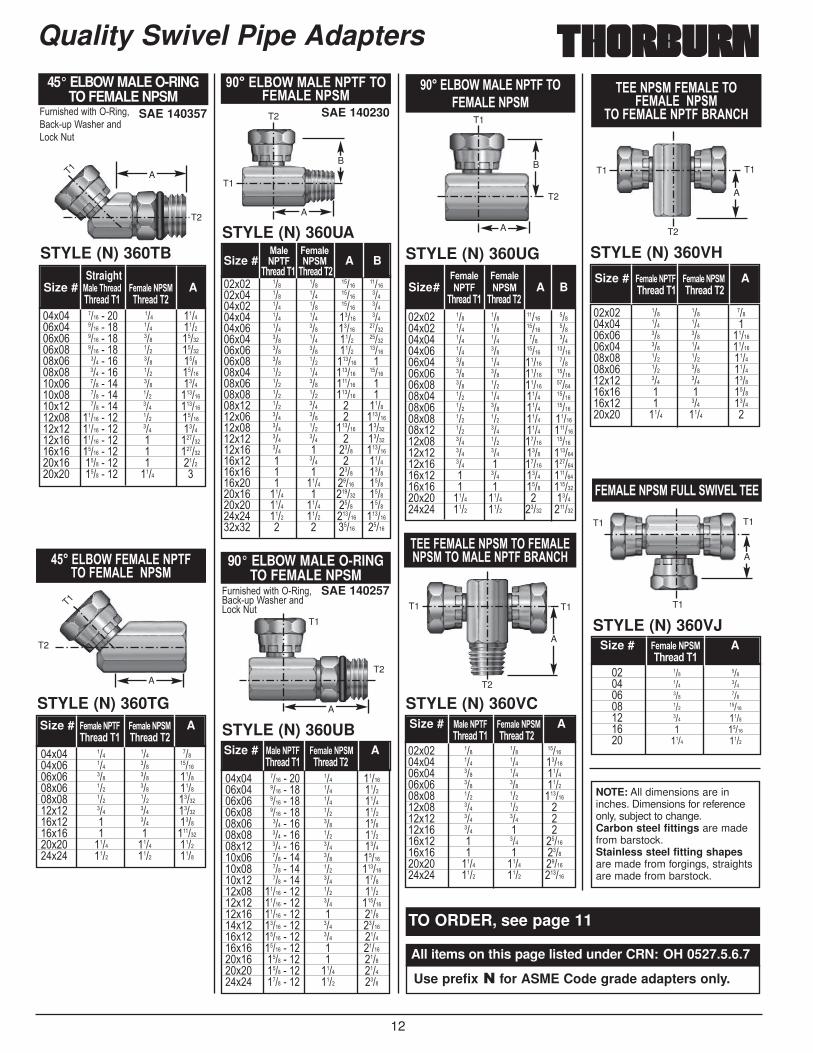
"�����$���%�������������%������%
STYLE (N) 360UG
������%������%������%�����%����%�������� $����'
STYLE (N) 360VC
������%���%��������%�������%�
�����%�������� $����'
STYLE (N) 360VH
��%������%��#�� ����� ���
STYLE (N) 360VJ
��$�� ��� ��� �������$�� ��� ��� �������$�� ��� ��� ������$�� ��� ��� ������$�� ��� ��� ��������$�� ��� ��� ���$�� ��� ��� ���$�� ��� � ���$�� � ��� �������$�� � � ������$�� ���� ���� �������$�� ���� ���� ������
Size # %/5-����� �-8/5-���% A�.)-/0��� �.)-/0���
��$�� ��� ��� ����� �����$�� ��� ��� ����� �����$�� ��� ��� ��� �����$�� ��� ��� ����� �������$�� ��� ��� ����� �����$�� ��� ��� ����� �������$�� ��� ��� ����� �������$�� ��� ��� ���� �������$�� ��� ��� ���� �������$�� ��� ��� ���� �������$�� ��� ��� ���� ��������$�� ��� ��� ����� �������$�� ��� ��� ���� ��������$�� ��� � ����� ��������$�� � ��� ���� ��������$�� � � ���� ��������$�� ���� ���� � ������$�� ���� ���� ����� ������
�-8/5-� �-8/5-�Size# ���� ��% A B
�.)-/0��� �.)-/0�����$�� ��� ��� �����$�� ��� ��� ���$�� ��� ��� �������$�� ��� ��� �������$�� ��� ��� ������$�� ��� ��� ������$�� ��� ��� ������$�� � � ������$�� � ��� ������$�� ���� ���� �
Size # �-8/5-����� �-8/5-���% A�.)-/0��� �.)-/0���
�� ��� ����� ��� ����� ��� ����� ��� ������� ��� ������ � ������� ���� ����
Size # �-8/5-���% A�.)-/0���
"�����$���%�������������%������%
SAE 140230
STYLE (N) 360UA
��$�� ��� ��� ����� �������$�� ��� ��� ����� �����$�� ��� ��� ����� �����$�� ��� ��� ����� �����$�� ��� ��� ����� �������$�� ��� ��� ���� �������$�� ��� ��� ���� �������$�� ��� ��� ������ ���$�� ��� ��� ������ �������$�� ��� ��� ������ ���$�� ��� ��� ������ ���$�� ��� ��� � ������$�� ��� ��� � ��������$�� ��� ��� ������ �������$�� ��� ��� � �������$�� ��� � ���� ��������$�� � ��� � ������$�� � � ���� ������$�� � ���� ����� ������$�� ���� � ������ ������$�� ���� ���� ���� ������$�� ���� ���� ������ ��������$�� � � ����� �����
%/5-� �-8/5-�Size # ���� ��% A B
�.)-/0��� �.)-/0���
90° ELBOW MALE O-RING TO FEMALE NPSM
SAE 140257
STYLE (N) 360UBSize # %/5-����� �-8/5-���% A
�.)-/0��� �.)-/0�����$�� ���� ���� ��� �������$�� ���� ���� ��� ������$�� ���� ���� ��� ������$�� ���� ���� ��� ������$�� ��� ���� ��� ������$�� ��� ���� ��� ������$�� ��� ���� ��� ������$�� ��� ���� ��� �������$�� ��� ���� ��� ��������$�� ��� ���� ��� ������$�� ����� ���� ��� ������$�� ����� ���� ��� ��������$�� ����� ���� � ������$�� ����� ���� ��� �������$�� ����� ���� ��� ������$�� ����� ���� � �������$�� ���� ���� � ������$�� ���� ���� ���� ������$�� ���� ���� ���� ����
4.���'���A�)����0���!�,:�.(�?'�����<�,:�%.)
A
T2
T1
T2
T1 T1
T1T1T1
T2
T1T1
A
T1
T2
T2
T1
B
A
B
A
A
A� ����$�����%��������������%�������%
STYLE (N) 360TG
��$�� ��� ��� �����$�� ��� ��� �������$�� ��� ��� ������$�� ��� ��� ������$�� ��� ��� �������$�� ��� ��� �������$�� � ��� ������$�� � � ��������$�� ���� ���� ������$�� ���� ���� ����
Size # �-8/5-����� �-8/5-���% A�.)-/0��� �.)-/0���
T2
T1
A
NOTE: All dimensions are ininches. Dimensions for referenceonly, subject to change.Carbon steel fittings are madefrom barstock.Stainless steel fitting shapesare made from forgings, straightsare made from barstock.
TO ORDER, see page 11
All items on this page listed under CRN: OH 0527.5.6.7
Use prefix � for ASME Code grade adapters only.
45° ELBOW MALE O-RING TO FEMALE NPSM
SAE 140357
STYLE (N) 360TBStraight
Size # %/5-��.)-/0 �-8/5-���% A�.)-/0��� �.)-/0���
��$�� ���� ���� ��� ������$�� ���� ���� ��� ������$�� ���� ���� ��� �������$�� ���� ���� ��� �������$�� ��� ���� ��� ������$�� ��� ���� ��� �������$�� ��� ���� ��� ������$�� ��� ���� ��� ��������$�� ��� ���� ��� ��������$�� ����� ���� ��� �������$�� ����� ���� ��� ������$�� ����� ���� � ��������$�� ����� ���� � ��������$�� ���� ���� � ������$�� ���� ���� ���� �
4.���'���A�)����0���!�,:�.(�?'�����<�,:�%.)
T1A
T2

13
37° FlareFittingTorque foot lbs.Steel & StainlessSteel Tube &
Size FittingMin. Max.
2 6 83 8 104 13 155 17 196 24 268 50 53
10 70 7512 95 10014 115 12016 130 13520 175 18524 215 22532 290 300
Carbon steel is made from barstock. Stainless steel shapes are madefrom forgings, straights are made from barstock.
Style 348F 02x02 S6 is a male connector with precisionmachined 1/8” tube OD 37° male flare tube 5/16”-24 thread by 1/8” male pipe 1/8”-27 thread made from type 316 stainless steel.
37° Flare Tube Fittings and Hose Adapters
Note: Torque values are for StainlessSteel Fittings only.The minimum torquevalues shown were established on thebasis of having a smooth contact surfacebetween the flare and the seat of thefitting. Do not lubricate threads.
"#$%���#���%����������&�'Thorburn offers the widest warrantyof 37° tube fittings in the world.
COMPLIANCES & CONFORMANCES
■ SAE J514
■ ASME Section III; B31.1; B51;ASME Section VIII; B31.3; c/w CRN.
■ Military Specification MIL-F-18866
■ Military Standards MS 51500
HOW TO ORDER THORBURN COMMERCIAL GRADEPRECISION MACHINED 37° FLARE TUBE FITTINGS
$/4-��;81-)�E*)�3D5-�*E��0/3-)
%/3-),/5B���1 ���3��$�1��''3����1/�2��� )��53
��'��)�� A����<*85-3-�E,33,+>�9,3.�+;34�@45--2-4 ��-.�����14���1*0D�*+5D 8�$5/+?3
Example: 348F 02x02 S6
COMMERCIAL MATERIAL SPECIFICATIONS
��%$�( ���G#����$�����������������������
Example: N 348 F 08x08 S6 Class 2
Style N 348F 08x08 S6 class 2 is a male connector with ���7pre-cision machined 37° flare (���-16) tube with ���7male pipe threadsin 316 type stainless steel for ASME class 2 service.
HOW TO ORDER THORBURN ASME CODE GRADEPRECISION MACHINED 37° FLARE HOSE ADAPTER
TUBE FITTING BODIES
"��#�$�%&��'�#�))���&��)'�� *+,�����-.����&��)'����'�/0%1/���0���')���%.&2��3�
�'��(�)�.&2������4�'��*5�/����,)���A�)��.2��)��*5�"�(�������
'��'�6�'�.&2���'(�,��#��'�� �).2�'�6��#��')��(�(��)����5')� �6�'�����������7���.'!���$���8���7$���7�
*)���5�,��������'� �� )����)'�&���# �����)D(������ �(�'�1#����3&���#� ����)D(��������)����&)���5'��525��.(����-.�')�
4����.,5��,5''�'���'��)'.##�$ �5/44��!��������4���,5''�!�5����25�:�
Class 2S608x08348FN�/)3�+;81-) �/4.�4,=-4 %/3-),/5 �*0-��5/44
Example: N 349FA 08x08 S6 Class 3
Style 349FA is an assembly consisting of a 316 type stainlesssteel 90° elbow with ���B precision machined 37° flare tube with���B male pipe threads, complete with nuts and sleeve for ASME
class 3 service. (FA=Fitting Assembly)
HOW TO ORDER THORBURN ASME CODE GRADE 37° FLARED TUBE FITTING ASSEMBLIES
"��#�$�%�&��'#�))����&��)'� *+�,����-.���&��)'���'��/0%1/���0���')���%.&2��3�
"�)��.&2�����4��'�����+52�A�A�)���.2�)��*5��"�(�����!�,�&�(5�)��A�)���.)'��'5�����
'��'�6���.&�2���'(�,�#��'�� ).2��'�6��#��')���(�(��)���5')�� �6�'����������7����.'!��$���8����7$���7
)����)'�&���# �����)D(������ �(�'�1#����3&���#� ����)D(��������)���&)���5'���525�.(�����-.�')�
4����.,5��,5''�'���'��)'.##�$ �5/44��!� ������4��,5''��!�5���25�:�
Class 2S608x08349FAN�/)3�+;81-) �/4.�4,=-4 %/3-),/5 �*0-��5/44
�/4.�4,=-4�;1-�����������7��#�����,�
�,-�4,=- �������7��#�����,�
DESIGN PRESSURE RATING
� ��� ����� ����� �!���� ��� ����� ���� �!���� ��� ����� ���� �!���� ��� ����� ����� �!����� ��� �!����� ��� ����� ����� �!����� � ����� ����� �!����� ���� ������ ����� �!����� ���� ������ ������ �!����� � ������ ����� �!���
�A� ���� '�����A��'���� 6���'�7 ������
%��� ��%� ���#��
Note: Higher pressure ratings avail-able on request.
Nut Sleeve Body
�*)>-0�$*0,-4 B283 A576 12L14 A182 316
$/)43*<?�$*0,-4 B21/ B16 A108 12L14 A479 316
�*50��*)8-0��;1-��;34 — A578 C1110 A479 316
�*50��*)8-0��;1-�5--2-4 — SAE1020 A276 316
$/)43*<?��;1-��;34 — A108 12L14 A479 316
$/)43*<?��;1-�5--2-4 — A108 C1137 A276 316
Brass Steel Stainless 37° Flare Steel
ASTM ASTM Type ASTM Type
348F 02x02 S6 A
14
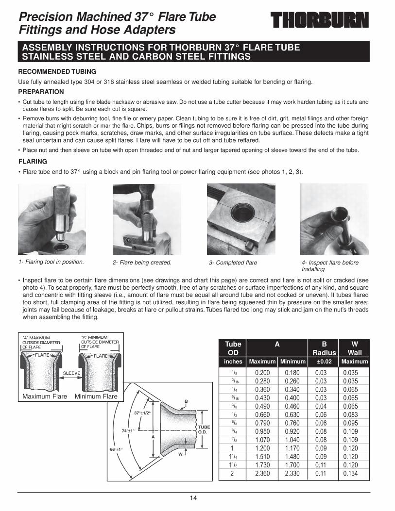
Maximum Flare Minimum Flare
RECOMMENDED TUBING
Use fully annealed type 304 or 316 stainless steel seamless or welded tubing suitable for bending or flaring.
FLARING
• Flare tube end to 37° using a block and pin flaring tool or power flaring equipment (see photos 1, 2, 3).
• Inspect flare to be certain flare dimensions (see drawings and chart this page) are correct and flare is not split or cracked (seephoto 4). To seat properly, flare must be perfectly smooth, free of any scratches or surface imperfections of any kind, and squareand concentric with fitting sleeve (i.e., amount of flare must be equal all around tube and not cocked or uneven). If tubes flaredtoo short, full clamping area of the fitting is not utilized, resulting in flare being squeezed thin by pressure on the smaller area;joints may fail because of leakage, breaks at flare or pullout strains. Tubes flared too long may stick and jam on the nut’s threadswhen assembling the fitting.
PREPARATION
• Cut tube to length using fine blade hacksaw or abrasive saw. Do not use a tube cutter because it may work harden tubing as it cuts andcause flares to split. Be sure each cut is square.
• Remove burrs with deburring tool, fine file or emery paper. Clean tubing to be sure it is free of dirt, grit, metal filings and other foreignmaterial that might scratch or mar the flare. Chips, burrs or filings not removed before flaring can be pressed into the tube duringflaring, causing pock marks, scratches, draw marks, and other surface irregularities on tube surface. These defects make a tightseal uncertain and can cause split flares. Flare will have to be cut off and tube reflared.
• Place nut and then sleeve on tube with open threaded end of nut and larger tapered opening of sleeve toward the end of the tube.
Precision Machined 37° Flare TubeFittings and Hose Adapters
��� ����� ����� ���� ��������� ����� ����� ���� �������� ����� ����� ���� ��������� ����� ����� ���� �������� ����� ����� ���� �������� ����� ����� ���� �������� ����� ����� ���� �������� ����� ����� ���� �������� ����� ����� ���� ������ ����� ����� ���� ��������� ����� ����� ���� ��������� ����� ����� ���� ������ ����� ����� ���� �����
Tube A B WOD Radius Wall
inches Maximum Minimum ±0.02 Maximum
ASSEMBLY INSTRUCTIONS FOR THORBURN 37° FLARE TUBE STAINLESS STEEL AND CARBON STEEL FITTINGS
1- Flaring tool in position. 2- Flare being created. 3- Completed flare 4- Inspect flare beforeInstalling
15
37° Flare Tube Fittings and Hose Adapters
Number of Flats of Nut to Turn Torque
Tube Nut With Tubing Swivel Nut Fitting Foot Pounds
OD Hex Minimum Maximum Minimum Maximum Minimum Maximum
2 3/8 21/4 21/2 21/4 21/2 6 8
3 7/16 21/4 21/2 21/4 21/2 8 10
4 9/16 2 21/4 2 21/4 13 15
5 5/8 2 21/4 2 21/4 17 19
6 11/16 11/2 13/4 11/4 11/2 24 26
8 7/8 11/2 13/4 1 11/4 50 53
10 1 11/2 13/4 1 11/4 70 75
12 11/4 11/4 11/2 1 11/4 95 100
14 13/8 1 11/4 1 11/4 115 120
16 11/2 1 11/4 1 11/4 130 135
20 2 1 11/4 1 11/4 175 185
24 21/4 1 11/4 1 11/4 215 225
32 27/8 1 11/4 1 11/4 290 300
ASSEMBLY TORQUE TABLE FOR 37° FLARE FITTINGTHORBURN 37° FLARED TUBEFITTINGS that require “O” ringsare shipped with the “O” ringsinstalled. If it becomes neces-sary to replace the “O” ring,lubricate the replacement “O” ring with a light coating of oilor petroleum jelly. Stretch the“O” ring and carefully roll it overthe fitting threads into the “O” ring groove, being carefulnot to nick or cut the “O” ring onthe threads. A damaged “O” ringcould lead to leakage. Once the“O” ring has been installed, finalassembly to an SAE straightthread port can be accom-plished. Properly installedThorburn “O” rings provide adependable seal.
Thorburn standard “O” ring ismade of Buna-N material.
Other materials available onspecial order.
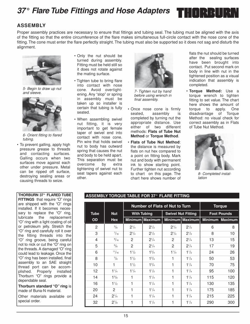
5- Begin to draw up nutand sleeve.
6- Orient fitting to flaredtubing.
7- Tighten nut by handbefore using wrench infinal assembly.
8- Completed instal-lation
ASSEMBLYProper assembly practices are necessary to ensure that fittings and tubing seal. The tubing must be aligned with the axisof the fitting so that the entire circumference of the flare makes simultaneous full-circle contact with the nose cone of thefitting. The cone must enter the flare perfectly straight. The tubing must also be supported so it does not sag and disturb thealignment.
• To prevent galling, apply highpressure grease to threadsand contacting surfaces.Galling occurs when twosurfaces move against eachother under pressure. Metalcan be ripped off surface,destroying sealing areas orcausing threads to seize.
• Only the nut should beturned during assembly.Fitting must be held still soit does not rotate againstthe mating surface.
• Tighten tube to bring flareinto contact with nosecone. Avoid overtight-ening. Any “slop” or springin assembly must betaken up so installer iscertain that tubing is fullyseated.
• When assembling swivelnut fitting, it is veryimportant to get femaletaper of swivel end intocontact with nose cone.Pin wire that holds swivelnut to body has outwardspring that causes the nutand body to be held apart.This separation must beovercome by extratightening of swivel nut toseat tapers against eachother.
• Once nose cone is firmlyseated, assembly iscompleted by turning nut theappropriate distance. Useeither of two differentmethods: Flats of Tube NutMethod or Torque Method.
• Flats of Tube Nut Method:the distance is measured byflats on nut hex compared toa point on fitting body. Marknut and body with permanentink to show starting point.Further tighten nut accordingto chart on this page. Thechart here shows number of
flats the nut should be turnedafter the sealing surfaceshave been brought intocontact. Put second mark onbody in line with nut in thetightened position as a visualindication that assembly iscompleted.
• Torque Method: Use atorque wrench to tightenfitting to set value. The charthere shows the amount oftorque to apply. Onedisadvantage of TorqueMethod: no visual check forcorrect assembly as in Flatsof Tube Nut Method.
16
Precision Machined 37° Flare TubeFittings and Hose Adapters
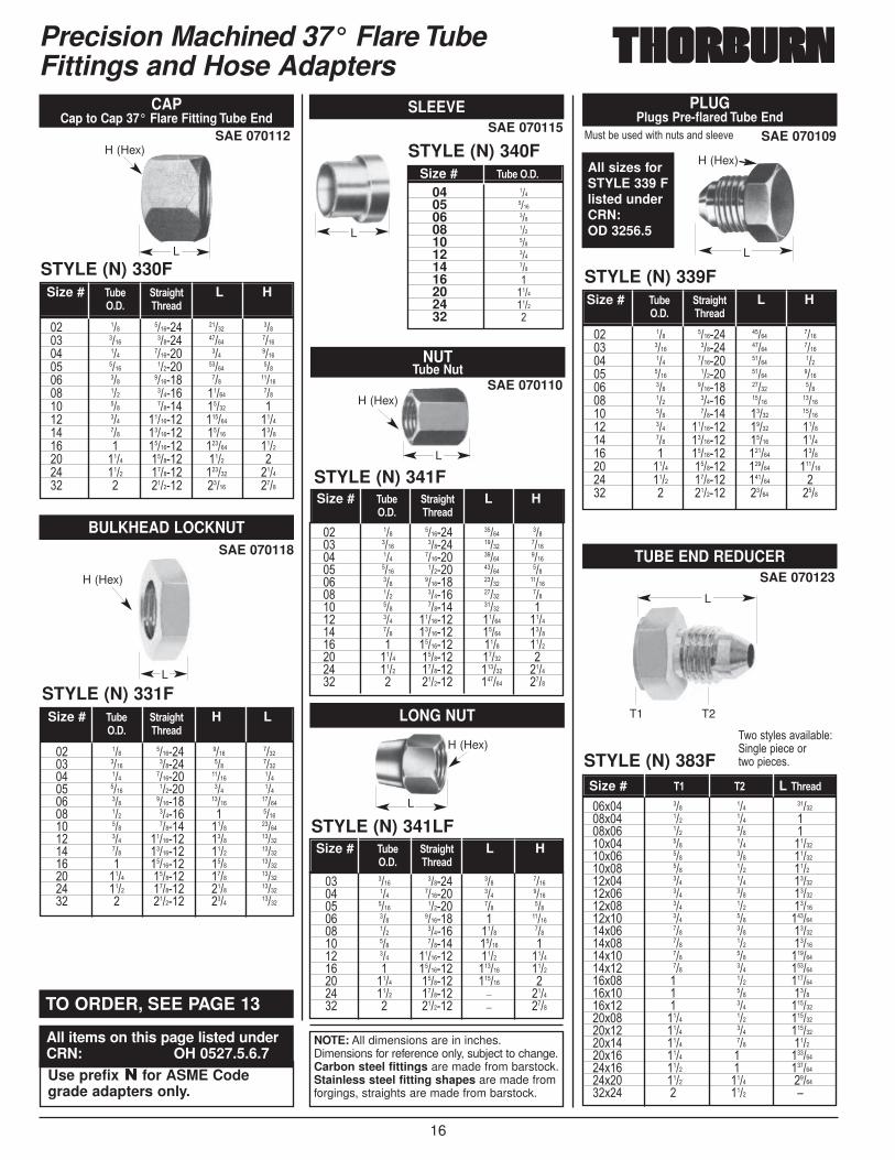
CAPCap to Cap 37° Flare Fitting Tube End
SAE 070112
SAE 070110
SLEEVESAE 070115
STYLE (N) 330F
SAE 070118
STYLE (N) 331F
NUTTube Nut
STYLE (N) 341F
LONG NUT
BULKHEAD LOCKNUT
SAE 070123
STYLE (N) 383F
TUBE END REDUCER
STYLE (N) 341LF
PLUGPlugs Pre-flared Tube End
SAE 070109
STYLE (N) 339F
*.')�2��.'��A�)���.)'���'5����STYLE (N) 340F
�� ��� ������� ����� ����� ���� ������ ����� ������ ��� ������� ��� ������ ���� ������ ����� ����� ��� ������� ��� ������� ��� ������ ����� ����� ��� ������ ����� ��� ��� �������� ������ ������ ��� �������� ����� ������ � �������� ������ ������ ���� ������� ���� ��� ���� ������� ������ ������ � ������� ����� ����
04 ���05 ����06 ���08 ���10 ���12 ���14 ���16 �20 ����24 ����32 �
Size # �;1- 3)/,>.3 L H���� �.)-/0
�� ��� ������� ���� ������ ���� ������ ��� ������ ��� ������� ����� ����� ���� ������ ��� ����� ��� ������� ����� ������� ��� ������ � ������ ��� ������ ���� ������� ��� �������� ���� ������� ��� �������� ���� ������� � �������� ���� ������� ���� ������� ���� ������� ���� ������� ���� ������� � ������� ���� �����
Size # �;1- 3)/,>.3 H L���� �.)-/0
��$�� ��� ��� �������$�� ��� ��� ���$�� ��� ��� ���$�� ��� ��� �������$�� ��� ��� �������$�� ��� ��� ������$�� ��� ��� �������$�� ��� ��� �������$�� ��� ��� �������$�� ��� ��� ��������$�� ��� ��� �������$�� ��� ��� �������$�� ��� ��� ��������$�� ��� ��� ��������$�� � ��� ��������$�� � ��� ������$�� � ��� ��������$�� ���� ��� ��������$�� ���� ��� ��������$�� ���� ��� ������$�� ���� � ��������$�� ���� � ��������$�� ���� ���� �������$�� � ���� E
Size # �� �� L �.)-/0
Size # �;1-�����
�� ��� ������� ����� ������ ���� ������ ����� ������ ��� ������� ����� ����� ���� ������ ����� ������ ��� ������� ����� ����� ��� ������ ����� ������� ��� ������ ����� ������� ��� �������� ����� ������ ��� �������� ����� ������ � �������� ������ ������ ���� ������� ������ �������� ���� ������� ������ ��� � ������� ����� ����
Size # �;1- 3)/,>.3 L H���� �.)-/0
�� ��� ������� ����� ����� ���� ������ ����� ������ ��� ������� ����� ������ ���� ������ ����� ����� ��� ������� ����� ������� ��� ������ ����� ����� ��� ������ ����� ��� ��� �������� ����� ������ ��� �������� ����� ������ � �������� ���� ������ ���� ������� ����� ��� ���� ������� ������ ������ � ������� ������ ����
Size # �;1- 3)/,>.3 L H���� �.)-/0
�� ���� ������ ��� ������ ��� ������� ��� ������ ���� ������ ��� ����� ��� ������� � ������� ��� ������ ���� ����� ��� ������ ����� ��� ��� �������� ���� ������ � �������� ������ ������ ���� ������� ������ ��� ���� ������� ; ������ � ������� ; ����
Size # �;1- 3)/,>.3 L H���� �.)-/0
L
H (Hex)
L
H (Hex)
L
H (Hex)
L
H (Hex)
L
L
T1 T2
L
H (Hex)
All sizes forSTYLE 339 Flisted underCRN:OD 3256.5
NOTE: All dimensions are in inches.Dimensions for reference only, subject to change.Carbon steel fittings are made from barstock.Stainless steel fitting shapes are made fromforgings, straights are made from barstock.
�A��')D5�'���525�9 ���5��(��,�����)A��(��,�'�
TO ORDER, SEE PAGE 13
All items on this page listed underCRN: OH 0527.5.6.7Use prefix � for ASME Codegrade adapters only.
17
Precision Machined 37° Flare TubeFittings and Hose Adapters
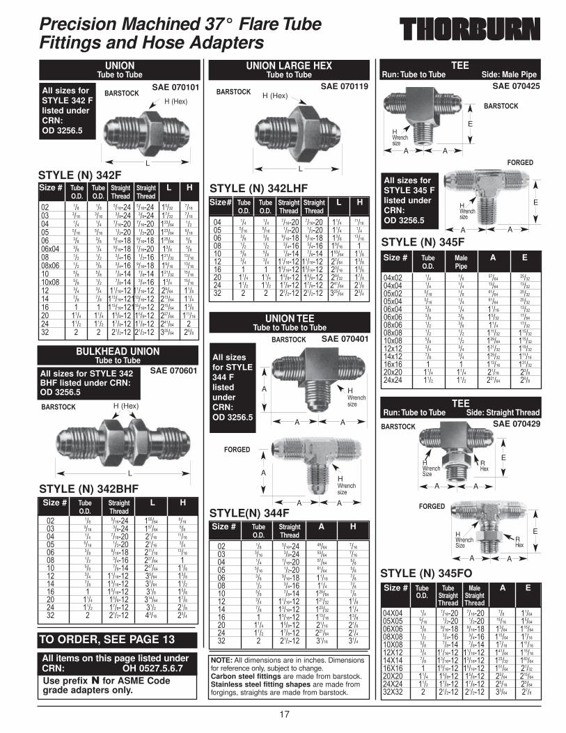
STYLE (N) 342F
SAE 070101$�����&
$�����&
������
$�����&
������
$�����&
������
$�����&
$�����&
UNIONTube to Tube
STYLE (N) 342LHF
SAE 070119
UNION LARGE HEXTube to Tube
STYLE(N) 344F
SAE 070401
UNION TEETube to Tube to Tube
STYLE (N) 342BHF
BULKHEAD UNIONTube to Tube
SAE 070601
�� ��� ��� ������� ������� ����� ������ ���� ���� ������ ������ ����� ������ ��� ��� ������� ������� ������ ����� ���� ���� ������ ������ ������ ������ ��� ��� ������� ������� ������ �����$�� ��� ��� ������� ������� ���� ����� ��� ��� ������ ������ ������ �������$�� ��� ��� ������ ������� ����� ������� ��� ��� ������ ������ ������ �������$�� ��� ��� ������ ������ ���� ������� ��� ��� �������� �������� ����� ������ ��� ��� ������������������ ������ ������ � � ������������������ ������ ������ ���� ���� ������� ������� ������ �������� ���� ���� ������� ������� ������ ��� � � ������� ������� ������ ����
�� ��� ��� ������� ������� ���� ������� ���� ���� ������ ������ ���� ����� ��� ��� ������� ������� ���� ������� ��� ��� ������ ������ ����� ��� ��� ��� ������ ������ ������ ������ ��� ��� �������� �������� ����� ������ � � �������� �������� ����� ������ ���� ���� ������� ������� ����� ������ ���� ���� ������� ������� ������ ������ � � ������� ������� ������ ����
Size # �;1- �;1- 3)/,>.3 3)/,>.3 L H���� ���� �.)-/0 �.)-/0
Size# �;1- �;1- 3)/,>.3 3)/,>.3 L H���� ���� �.)-/0 �.)-/0
�� ��� ������� ������ ������ ���� ������ ������ ����� ��� ������� ����� ������� ���� ������ ����� ����� ��� ������� ������ ������� ��� ������ ������ ��� ��� ������ ������ ������ ��� �������� ����� ������ ��� �������� ����� ������ � �������� ���� ������ ���� ������� ������ ������ ���� ������� ���� ������ � ������� ����� ����
Size # �;1- 3)/,>.3 L H���� �.)-/0
�� ��� ������� ����� ������ ���� ������ ����� ������ ��� ������� ����� ����� ���� ������ ����� ����� ��� ������� ����� ����� ��� ������ ���� ����� ��� ������ ������ ����� ��� �������� ������ ������ ��� �������� ������ ������ � �������� ������ ������ ���� ������� ����� ������ ���� ������� ������ ������ � ������� ����� ����
Size # �;1- 3)/,>.3 A H���� �.)-/0
L
H (Hex)
AA
AH ?���,�'�6�
AA
A H ?���,�'�6�
L
H (Hex)
H (Hex)
L
SAE 070429
STYLE (N) 345FO
TEERun: Tube to Tube Side: Straight Thread
��>�� ��� ������� ������� ��� �������>�� ���� ������ ������ ����� �������>�� ��� ������� ������� ����� ��������>�� ��� ������ ������ ������ �������>�� ��� ������ ������ ����� ��������>�� ��� �������� �������� ������ ��������>�� ��� �������� �������� ������ ��������>�� � �������� �������� ������ �������>�� ���� ������� ������� ����� ��������>�� ���� ������� ������� ����� �������>�� � ������� ������� ����� ����
Size # �;1- �;1-� %/5-� A E���� 3)/,>.3 3)/,>.3
�.)-/0 �.)-/0
R=�$
HWrench �6�
AA
E
R=�$
HWrench �6�
AA
E
SAE 070425
STYLE (N) 345F
TEERun: Tube to Tube Side: Male Pipe
��$�� ��� ��� ����� �������$�� ��� ��� ����� �������$�� ���� ��� ����� �������$�� ���� ��� ����� �������$�� ��� ��� ����� �������$�� ��� ��� ����� �������$�� ��� ��� ���� �������$�� ��� ��� ������ ��������$�� ��� ��� ������ ��������$�� ��� ��� ������ ��������$�� ��� ��� ������ ��������$�� � � ������ ��������$�� ���� ���� ����� ������$�� ���� ���� ������ ����
Size # �;1- %/5- A E���� �,-
H?���,�'�6�
AA
E
H?���,�'�6�
AA
E
All sizesfor STYLE344 FlistedunderCRN:OD 3256.5
All sizes forSTYLE 345 Flisted underCRN:OD 3256.5
All sizes forSTYLE 342 Flisted underCRN:OD 3256.5
All sizes for STYLE 342BHF listed under CRN:OD 3256.5
NOTE: All dimensions are in inches. Dimensionsfor reference only, subject to change.Carbon steel fittings are made from barstock.Stainless steel fitting shapes are made fromforgings, straights are made from barstock.
TO ORDER, SEE PAGE 13
All items on this page listed underCRN: OH 0527.5.6.7Use prefix � for ASME Codegrade adapters only.
18
Precision Machined 37° Flare TubeFittings and Hose Adapters
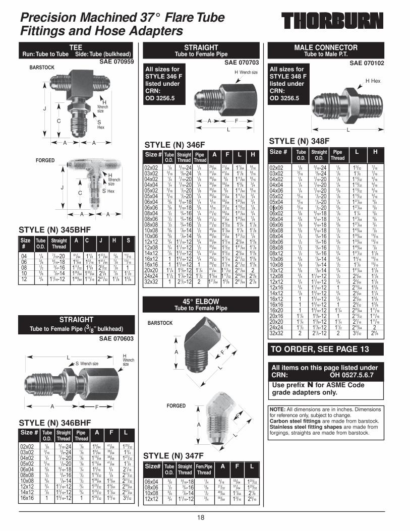
SAE 070102
MALE CONNECTORTube to Male P.T.
SAE 070959
������
$�����&
������
$�����&
TEERun: Tube to Tube Side: Tube (bulkhead)
STYLE (N) 345BHF
�� ��� ������� ����� ���� ������ ��� ������� ��� ������� ����� ����� ������ ��� ������� ��� ������ ������ ���� ����� ��� ��� ��� ������ ������ ������ ���� ��� ������ ��� �������� ������ ������ ������ ���� ����
,=-� �;1- 3)/,>.3 � � � ' H ���� �.)-/0
JC
A A
H ?���,�'�6�
S =�$
STYLE (N) 348F
��$�� ��� ������� ��� ����� ������$�� ���� ������ ��� ���� ������$�� ��� ������� ��� ������ ������$�� ��� ������� ��� ������ ������$�� ��� ������� ��� ������ ������$�� ���� ������ ��� ������ ������$�� ���� ������ ��� ������ �����$�� ���� ������ ��� ������ �����$�� ��� ������� ��� ���� �����$�� ��� ������� ��� ������ �����$�� ��� ������� ��� ������ �����$�� ��� ������� ��� ������ �����$�� ��� ������ ��� ������ �������$�� ��� ������ ��� ������ �������$�� ��� ������ ��� ������ �����$�� ��� ������ ��� ������ ������$�� ��� ������ ��� ����� �������$�� ��� ������ ��� ���� �������$�� ��� ������ ��� ������ ������$�� ��� �������� ��� ����� ������$�� ��� �������� ��� ����� ������$�� ��� �������� � ������ ������$�� ��� �������� ��� ����� ������$�� � �������� ��� ����� ������$�� � �������� � ����� ������$�� � �������� ���� ������ ��������$�� ���� ������� � ������ ��������$�� ���� ������� ���� ����� ��������$�� ���� ������� ���� ������ ���$�� � ������� � ����� ����
Size # �;1- 3)/,>.3 �,- L H���� ���� �.)-/0
J
C
A A
H ?���,�'�6�
S=�$ L
H Hex
45° ELBOWTube to Female Pipe
STYLE (N) 347F
��$�� ��� ������� ��� ���� ����� ��������$�� ��� ������ ��� ����� ����� ��������$�� ��� ������ ��� ����� ����� ������$�� ��� �������� ��� ����� ����� �����
Size# �;1- 3)/,>.3 �-8��,- A F L���� �.)-/0 �.)-/0
F
L
F
L
SAE 070703
STRAIGHTTube to Female Pipe
STYLE (N) 346F
��$�� ��� ������� ��� ����� ����� ����� ������$�� ���� ������ ��� ����� ����� ���� ������$�� ��� ������� ��� ����� ��� ������ ������$�� ��� ������� ��� ����� ����� ���� �����$�� ���� ������ ��� ����� ��� ������ ������$�� ���� ������ ��� ����� ����� ������ �����$�� ��� ������� ��� ���� ����� ������ �����$�� ��� ������� ��� ���� ����� ������ �����$�� ��� ������ ��� ����� ����� ������ �����$�� ��� ������ ��� ����� ����� ������ �����$�� ��� ������ ��� ����� ����� ���� ������$�� ��� ������ ��� ����� ����� ���� ������$�� ��� ������ ��� ����� ����� ������ �����$�� ��� �������� ��� ����� ����� ����� ������$�� ��� �������� ��� ����� ����� ������ ������$�� ��� �������� ��� ����� ����� ����� ������$�� � �������� ��� ����� ����� ������ ������$�� � �������� � ����� ����� ������ ������$�� ���� ������� ���� ����� ������ ������ ���$�� ���� ������� ���� ����� ������ ������ ������$�� � ������� � ������ ���� ������ ����
Size # �;1- 3)/,>.3 �,- A F L H���� �.)-/0 �.)-/0
H ?���,��'�6�
A F
L
SAE 070603
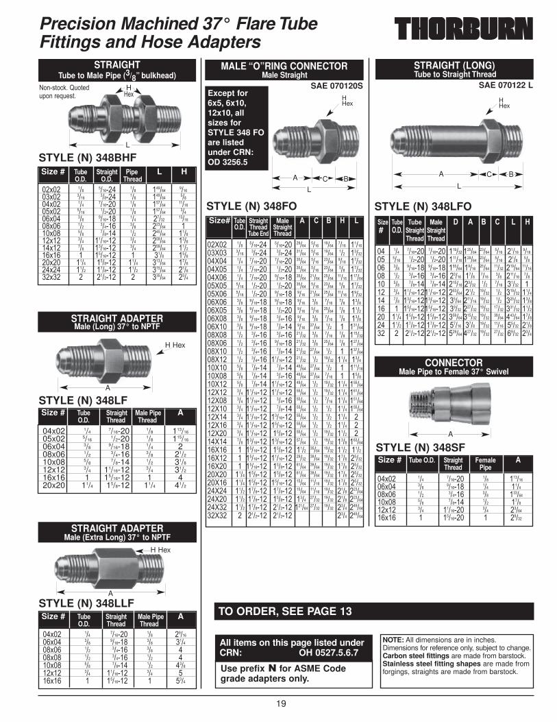
STRAIGHTTube to Female Pipe (3/8” bulkhead)
STYLE (N) 346BHF
��$�� ��� ������� ��� ����� ����� ��������$�� ���� ������ ��� ����� ����� ������$�� ��� ������� ��� ������ ����� ��������$�� ���� ������ ��� ������ ����� ������$�� ��� ������� ��� ����� ��� �������$�� ��� ������ ��� ������ ��� ��������$�� ��� ������ ��� ������ ����� ��������$�� ��� �������� ��� ������ ����� ��������$�� ��� �������� ��� ������ ����� ��������$�� � �������� � ������ ����� �����
Size # �;1- 3)/,>.3 �,- A F L���� �.)-/0 �.)-/0
H?���,�'�6�S ?���,��'�6�
A F
L
A
A
All sizes forSTYLE 346 Flisted underCRN:OD 3256.5
All sizes forSTYLE 348 Flisted underCRN:OD 3256.5
NOTE: All dimensions are in inches. Dimensionsfor reference only, subject to change.Carbon steel fittings are made from barstock.Stainless steel fitting shapes are made fromforgings, straights are made from barstock.
TO ORDER, SEE PAGE 13
All items on this page listed underCRN: OH 0527.5.6.7Use prefix � for ASME Codegrade adapters only.
19
Precision Machined 37° Flare TubeFittings and Hose Adapters
A
STRAIGHT ADAPTERMale (Long) 37° to NPTF
STYLE (N) 348LF
04x02 1/47/16-20 1/8 113/16
05x02 5/161/2-20 1/8 115/16
06x04 3/89/16-18 1/4 2
08x06 1/23/4-16 3/8 21/2
10x08 5/87/8-14 1/2 31/8
12x12 3/4 11/16-12 3/4 31/2
16x16 1 15/16-12 1 420x20 11/4 15/8-12 11/4 41/2
Size # �;1- 3)/,>.3 %/5-��,- A���� �.)-/0 �.)-/0
A
H Hex
A
H Hex
STRAIGHT ADAPTERMale (Extra Long) 37° to NPTF
STYLE (N) 348LLF
��$�� ��� ������� ��� �������$�� ��� ������� ��� ������$�� ��� ������ ��� ���$�� ��� ������ ��� ���$�� ��� ������ ��� ������$�� ��� �������� ��� ���$�� � �������� � ����
Size # �;1- 3)/,>.3 %/5-��,- A���� �.)-/0 �.)-/0
STYLE (N) 348SF
CONNECTORMale Pipe to Female 37° Swivel
��$�� ��� ������� ��� ��������$�� ��� ������� ��� ������$�� ��� ������ ��� ��������$�� ��� ������ ��� ������$�� ��� �������� ��� �������$�� � �������� � �����
Size # �;1-����� 3)/,>.3� �-8/5- ��.)-/0 �,-
STRAIGHTTube to Male Pipe (3/8” bulkhead)
STYLE (N) 348BHF
%���')�,:��F.�)�.(�����-.�')�
��$�� ��� ������� ��� ������ ������$�� ���� ������ ��� ������ �����$�� ��� ������� ��� ������ �������$�� ���� ������ ��� ������ �����$�� ��� ������� ��� ����� �������$�� ��� ������ ��� ������ ���$�� ��� ������ ��� ������ ������$�� ��� �������� ��� ������ ������$�� ��� �������� ��� ������ ������$�� � �������� � ���� ������$�� ���� ������� ���� ������ ������$�� ���� ������� ���� ������ ������$�� � ������� � ������ ����
Size # �;1- 3)/,>.3 �,- L H���� ���� �.)-/0
L
H=�$
SAE 070120S
STYLE (N) 348FO
MALE “O”RING CONNECTORMale Straight
��>�� ��� ������� ������� ����� ���� ����� ���� �������>�� ���� ������ ������ ����� ���� ����� ��� �������>�� ��� ������� ������� ����� ���� ����� ���� �������>�� ��� ������� ������ ����� ���� ����� ��� �������>�� ��� ������� ������� ����� ����� ����� ����� ��������>�� ���� ������ ������ ����� ���� ����� ��� �������>�� ���� ������ ������� ���� ����� ����� ����� �������>�� ��� ������� ������� ���� ��� ���� ��� ������>�� ��� ������� ������ ���� ���� ����� ��� ������>�� ��� ������� ������ ���� ��� ���� ��� ������>�� ��� ������� ������ ���� ����� ��� � ��������>�� ��� ������ ������ ����� ��� ���� ��� ��������>�� ��� ������ ������� ����� ��� ����� ��� ��������>�� ��� ������ ������ ����� ����� ��� � ��������>�� ��� ������ �������� ����� ��� ����� ���� ������>�� ��� ������ ������ ����� ����� ��� � ��������>�� ��� ������ ������ ����� ����� ���� � ������>�� ��� ������ �������� ����� ��� ����� ���� ��������>�� ��� �������� �������� ����� ��� ����� ���� ��������>�� ��� �������� ������ ����� ��� ���� ���� ��������>�� ��� �������� ������ ����� ��� ��� ���� ��������>�� ��� �������� �������� ����� ��� ��� ���� ���>�� ��� �������� �������� ����� ��� ��� ���� ���>�� ��� �������� ������� ����� ��� ����� ���� ���>�� ��� �������� �������� ����� ��� ����� ���� ��������>�� � �������� ������� ���� ����� ����� ���� ������>�� � �������� �������� ����� ����� ����� ���� �������>�� � �������� ������� ����� ����� ����� ���� �������>�� ���� ������� ������� ����� ����� ����� ���� �������>�� ���� ������� �������� ����� ����� ����� ���� �������>�� ���� ������� ������� ����� ����� ����� ���� ��������>�� ���� ������� ������� ���� ����� ����� ���� ��������>�� ���� ������� ������� ������ ����� ����� ���� ��������>�� � ������� ������� ���� ������
Size# �;1- 3)/,>.3 %/5- � � $ ' ����� �.)-/0 3)/,>.3
�;1-��+0 �.)-/0
HHex
BC
L
A
SAE 070122 L
STRAIGHT (LONG)Tube to Straight Thread
STYLE (N) 348LFO
�� ��� ������� ������� ������ ������ ����� ���� ����� ������ ���� ������ ������ ������ ������ ����� ���� ���� ����� ��� ������� ������� ������ ����� ����� ����� ������ ������� ��� ������ ������ ����� ���� ���� ��� ������ ����� ��� ������ ������ ������ ����� ��� ���� ����� ��� ��� ���������������� ������ ���� ����� ��� ������ ������ ��� ���������������� ����� ������ ����� ��� ������ ������ � ���������������� ����� ������ ����� ����� ������ ������ ���� ������� ������� ������ ������ ����� ����� ������ ������ ���� ������� ������� ����� ���� ����� ����� ����� ������ � ������� ������� ������ ������ ����� ����� ����� ����
,=- �;1- �;1- %/5- � � $ � � '# ���� 3)/,>.3 3)/,>.3
�.)-/0 �.)-/0
HHex
BCA
L
Except for6x5, 6x10,12x10, allsizes forSTYLE 348 FOare listedunder CRN:OD 3256.5
NOTE: All dimensions are in inches.Dimensions for reference only, subject to change.Carbon steel fittings are made from barstock.Stainless steel fitting shapes are made fromforgings, straights are made from barstock.
TO ORDER, SEE PAGE 13
All items on this page listed underCRN: OH 0527.5.6.7
Use prefix � for ASME Codegrade adapters only.
20
��$�� ��� ������� ��� ����� �������$�� ���� ������ ��� ����� �������$�� ��� ������� ��� ����� �������$�� ��� ������� ��� ����� �������$�� ��� ������� ��� ����� �������$�� ��� ������� ��� ����� ��������$�� ���� ������ ��� ����� �������$�� ���� ������ ��� ����� �������$�� ���� ������ ��� ����� �������$�� ��� ������� ��� ����� �������$�� ��� ������� ��� ����� �������$�� ��� ������� ��� ����� ��������$�� ��� ������ ��� ���� �������$�� ��� ������ ��� ���� �������$�� ��� ������ ��� ������ ��������$�� ��� ������ ��� ������ ��������$�� ��� ������ ��� ���� �������$�� ��� ������ ��� ������ ��������$�� ��� ������ ��� ������ ��������$�� ��� �������� ��� ������ ��������$�� ��� �������� ��� ������ ��������$�� ��� �������� � ������ ��������$�� ��� �������� � ������ ��������$�� � �������� ��� ������ ��������$�� � �������� � ������ ��������$�� ���� ������� � ����� ��������$�� ���� ������� ���� ����� ������$�� ���� ������� ���� ������ ������$�� ���� ������� ���� ������ ������$�� � ������� � ����� �
Precision Machined 37° Flare TubeFittings and Hose Adapters
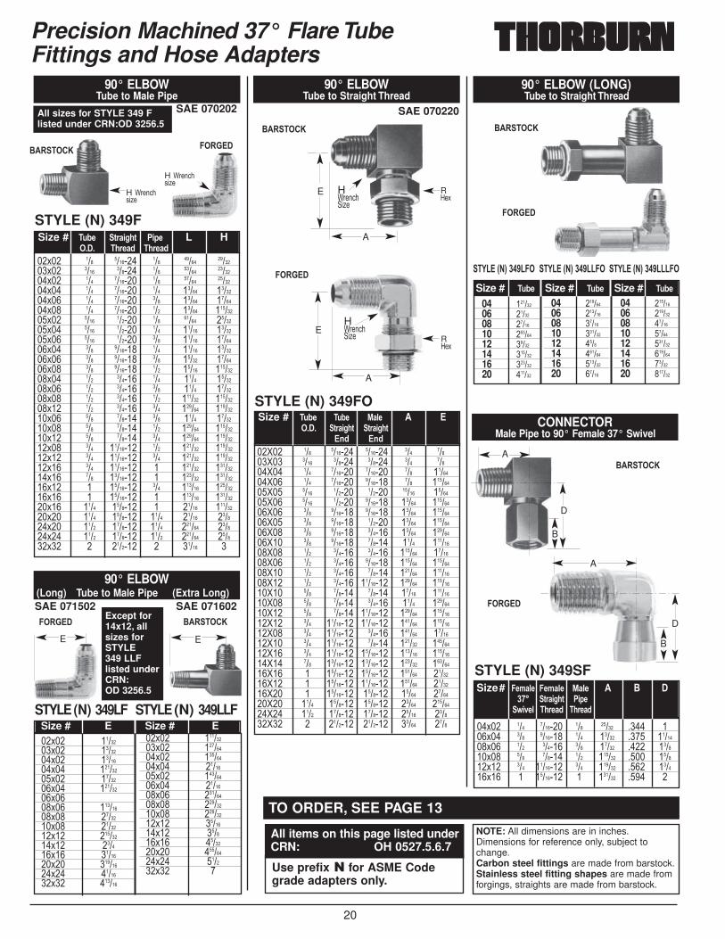
SAE 070202
90° ELBOWTube to Male Pipe
SAE 071502 SAE 071602
90° ELBOW(Long) Tube to Male Pipe (Extra Long)
��$�� �������$�� �������$�� �������$�� ��������$�� �������$�� ��������$����$�� ��������$�� �������$�� �������$�� ��������$�� ������$�� �������$�� ��������$�� �������$�� ������
��$�� ��������$�� ��������$�� ��������$�� �������$�� ��������$�� �������$�� ��������$�� ��������$�� ��������$�� �������$�� ������$�� �������$�� ��������$�� ������$�� �
STYLE (N) 349LF STYLE (N) 349LLFSize # E Size # E
H ?���,�'�6�
H ?���,�'�6�
E
STYLE (N) 349FSize # �;1- 3)/,>.3 �,- L H
���� �.)-/0 �.)-/0
E
STYLE (N) 349SF
CONNECTORMale Pipe to 90° Female 37° Swivel
��$�� ��� ������� ��� ����� ���� ���$�� ��� ������� ��� ����� ���� �������$�� ��� ������ ��� ����� ���� ������$�� ��� ������ ��� ������ ���� ������$�� ��� �������� ��� ������ ���� ������$�� � �������� � ������ ���� �
Size# �-8/5- �-8/5- %/5- � $ ���� 3)/,>.3 �,-
9,2-5 �.)-/0 �.)-/0
04 ������06 �����08 �����10 ������12 �����14 ������16 ������20 ������
04 ������06 ������08 �����10 ������12 ����14 ������16 ������20 �����
04 ������06 ������08 �����10 �����12 ������14 ������16 �����20 ������
�(�� 6�7���"��� �(�� 6�7���"���� �(���6�7���"�����
90° ELBOW (LONG)Tube to Straight Thread
Size # �;1- Size # �;1- Size # �;1-
SAE 070220
90° ELBOWTube to Straight Thread
STYLE (N) 349FO
��>�� ��� ������� ������� ��� �����>�� ���� ������ ������ ��� �����>�� ��� ������� ������� ��� �������>�� ��� ������� ������� ��� ��������>�� ���� ������ ������ ����� �������>�� ���� ������ ������� ����� ��������>�� ��� ������� ������� ����� ��������>�� ��� ������� ������ ����� ��������>�� ��� ������� ������ ����� ��������>�� ��� ������� ������ ���� ��������>�� ��� ������ ������ ������ �������>�� ��� ������ ������� ������ ��������>�� ��� ������ ������ ������ ��������>�� ��� ������ �������� ������ ��������>�� ��� ������ ������ ����� ��������>�� ��� ������ ������ ���� ��������>�� ��� ������ �������� ������ ��������>�� ��� �������� �������� ������ ��������>�� ��� �������� ������ ������ �������>�� ��� �������� ������ ������ ��������>�� ��� �������� �������� ������ ��������>�� ��� �������� �������� ������ ��������>�� � �������� �������� ������ �������>�� � �������� �������� ������ �������>�� � �������� ������� ����� �������>�� ���� ������� ������� ����� ��������>�� ���� ������� ������� ����� ������>�� � ������� ������� ����� ����
Size # �;1-� �;1-� %/5-� � ����� 3)/,>.3 3)/,>.3�
�+0 �+0
R=�$
H?���,� �6�
A
E
R=�$
H?���,� �6�
A
E
B
A
D
B
A
D
������$�����&
������
$�����&
������
$�����&������
$�����&
������
$�����&
Except for14x12, allsizes forSTYLE 349 LLFlisted underCRN:OD 3256.5
All sizes for STYLE 349 Flisted under CRN:OD 3256.5
NOTE: All dimensions are in inches.Dimensions for reference only, subject tochange.Carbon steel fittings are made from barstock.Stainless steel fitting shapes are made fromforgings, straights are made from barstock.
TO ORDER, SEE PAGE 13
All items on this page listed underCRN: OH 0527.5.6.7
Use prefix � for ASME Codegrade adapters only.
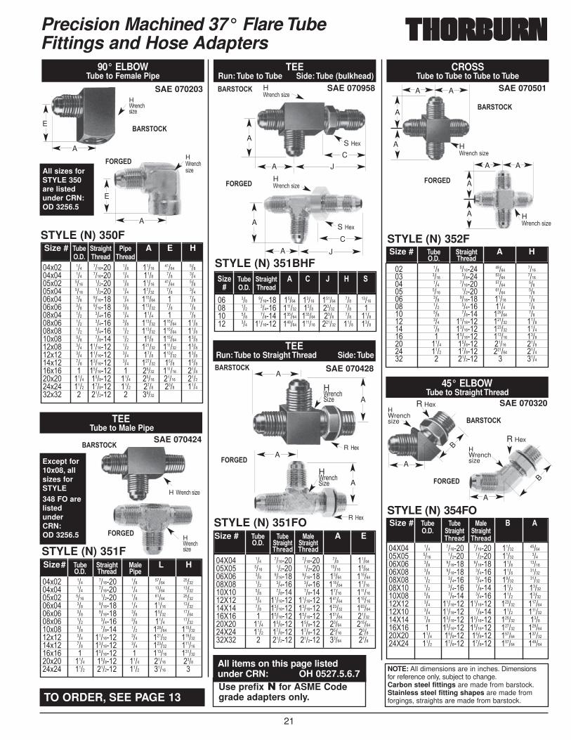
21
Precision Machined 37° Flare TubeFittings and Hose Adapters
SAE 070958
TEERun: Tube to Tube Side: Tube (bulkhead)
STYLE (N) 351BHF
�� ��� ������� ����� ����� ������ ��� ������� ��� ������ ������ ���� ����� ��� ��� ��� ������ ������ ������ ���� ��� ������ ��� �������� ������ ������ ������ ���� ����
,=-� �;1- 3)/,>.3 � � � ' H ���� �.)-/0
A
A
C
J
H ?���,��'�6�
S =�$
A
A J
H ?���,��'�6�
S =�$
SAE 070501
CROSSTube to Tube to Tube to Tube
STYLE (N) 352F
�� ��� ������� ����� ������ ���� ������ ����� ������ ��� ������� ����� ����� ���� ������ ����� ����� ��� ������� ����� ����� ��� ������ ���� ����� ��� ������ ������ ����� ��� �������� ������ ������ ��� �������� ������ ������ � �������� ������ ������ ���� ������� ����� ������ ���� ������� ������ ������ � ������� � ����
AA
A
A
H ?���,��'�6�
90° ELBOWTube to Female Pipe
STYLE (N) 350F
SAE 070203
��$�� ��� ������� ��� ����� ����� �����$�� ��� ������� ��� ���� ��� �����$�� ���� ������ ��� ����� ����� �����$�� ���� ������ ��� ����� ��� �����$�� ��� ������� ��� ������ � �����$�� ��� ������� ��� ������ ��� �����$�� ��� ������ ��� ���� � �����$�� ��� ������ ��� ������ ������ ������$�� ��� ������ ��� ������ ������ ������$�� ��� ������ ��� ���� ������ ������$�� ��� �������� ��� ������ ������ ������$�� ��� �������� ��� ���� ������ ������$�� ��� �������� ��� ������ ���� ������$�� � �������� � ����� ������ ������$�� ���� ������� ���� ����� ����� ������$�� ���� ������� ���� ���� ���� ������$�� � ������� � �����
Size # �;1- 3)/,>.3 �,- A E H���� �.)-/0 �.)-/0
H?���,�'�6�
A
E
H?���,�'�6�
A
E
SAE 070424
STYLE (N) 351F
TEETube to Male Pipe
��$�� ��� ������� ��� ����� �������$�� ��� ������� ��� ����� �������$�� ���� ������ ��� ����� �������$�� ��� ������� ��� ����� �������$�� ��� ������� ��� ����� �������$�� ��� ������ ��� ���� �������$�� ��� ������ ��� ������ ��������$�� ��� �������� ��� ������ ��������$�� ��� �������� ��� ������ ��������$�� � �������� � ������ ��������$�� ���� ������� ���� ����� ������$�� ���� ������� ���� ����� �
Size# �;1- 3)/,>.3 %/5- L H���� �.)-/0 �,-
H?���,�'�6�
SAE 070428
STYLE (N) 351FO
TEERun: Tube to Straight Thread Side: Tube
��>�� ��� ������� ������� ��� �������>�� ���� ������ ������ ����� �������>�� ��� ������� ������� ����� ��������>�� ��� ������ ������ ������ �������>�� ��� ������ ������ ����� ��������>�� ��� �������� �������� ������ ��������>�� ��� �������� �������� ������ ��������>�� � �������� �������� ������ �������>�� ���� ������� ������� ����� ��������>�� ���� ������� ������� ����� ������>�� � ������� ������� ����� ����
Size # �;1-� �;1-� %/5-� A E���� 3)/,>.3 3)/,>.3
�.)-/0 �.)-/0
R =�$
H?���,� �6� A
AR =�$
H?���,� �6� A
A
SAE 070320
STYLE (N) 354FO
45° ELBOWTube to Straight Thread
��>�� ��� ������� ������� ����� �������>�� ���� ������ ������ ����� �����>�� ��� ������� ������� ���� �������>�� ��� ������� ������ ���� �������>�� ��� ������ ������ ����� �������>�� ��� ������ ������ ���� �������>�� ��� ������ ������ ���� �������>�� ��� �������� �������� ������ ��������>�� ��� �������� ������ ���� ��������>�� ��� �������� �������� ������ ������>�� � �������� �������� ������ ��������>�� ���� ������� ������� ������ ��������>�� ���� ������� ������� ������ ������
Size # �;1-� �;1-� %/5-� $ ����� 3)/,>.3 3)/,>.3
�.)-/0 �.)-/0
R Hex
HWrenchsize
A
B
R HexHWrenchsize
A
B
H ?���,��'�6�
AA
A
A
H ?���,��'�6�C
$�����&
������
$�����&
������
$�����&
������
$�����&
������
$�����&
������
$�����&
������All sizes forSTYLE 350are listedunder CRN:OD 3256.5
Except for10x08, allsizes forSTYLE 348 FO arelistedunderCRN:OD 3256.5
NOTE: All dimensions are in inches. Dimensionsfor reference only, subject to change.Carbon steel fittings are made from barstock.Stainless steel fitting shapes are made fromforgings, straights are made from barstock.TO ORDER, SEE PAGE 13
All items on this page listedunder CRN: OH 0527.5.6.7Use prefix � for ASME Codegrade adapters only.
Size # �;1- 3)/,>.3 A H���� �.)-/0
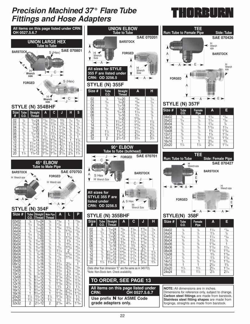
22
1 )��)����)����&��'����B+7����)���'&��'��������4�3�G%�)�9�%��� )�,:��)�&��/��,:���52�5�)D�
H �)-+<.4,=-
H �)-+<.4,=-
Precision Machined 37° Flare TubeFittings and Hose Adapters
A
STYLE (N) 354BHF
UNION LARGE HEXTube to Tube
SAE 070801
�� ��� ������� ����� ����� ���� ���� ������ ���� ������ ����� ����� ���� ���� ����� ��� ������� ����� ���� ������ ��� ������� ���� ������ ��� ���� ������ ��� ����� ��� ������� ���� ����� ������ ��� ������� ��� ������ ����� ���� ������ ��� ��� ��� ������ ����� ������ ����� � ������ ��� �������� ������ ������ ����� ���� ������ ��� �������� ������ ������ ���� ���� ������ � �������� ������ ������ ����� ���� ������ ���� ������� ������ ������ ������ ���� ����
,=-� �;1- 3)/,>.3 � � � ' H ���� �.)-/0
CJ
S (Hex)
A
CJ
S (Hex)
STYLE (N) 355BHF
90° ELBOWTube to Tube (bulkhead)
SAE 070701
�� ��� ������� ����� ����� ������ ������ ���� ������ ����� ����� ����� ������ ��� ������� ����� ���� ������ ������ ���� ������ ����� ���� ������ ����� ��� ������� ����� ����� ������ ����� ��� ������ ������ ���� ����� ����� ��� ������ ������ ������ ���� ��� ��� �������� ������ ������ ������ ������ ��� �������� ������ ������ ������ ������ � �������� ������ ������ ������ ������ ���� ������� ����� ������ ����� ����
Size �;1- 3)/,>.3 A C J H# ���� �.)-/0
CJ
H ?���,�� �6�
S HexA
CJ
H ?���,�� �6�S HexA
STYLE (N) 355F
SAE 070201
UNION ELBOWTube to Tube
�� ��� ������� ����� ������ ���� ������ ����� ������ ��� ������� ����� ����� ���� ������ ����� ����� ��� ������� ����� ����� ��� ������ ���� ����� ��� ������ ������ ��� ��� �������� ������ ������ ��� �������� ������ ������ � �������� ������ ������ ���� ������� ����� ������ ���� ������� ����� ������ � ������� ����� ����
Size # �;1- 3)/,>.3 A H���� �.)-/0
A
A H ?���,� �6�
A
A H ?���,� �6�
SAE 070427
STYLE(N) 358F
TEERun: Tube to Tube Side: Female Pipe
��$�� ��� ��� ����� �������$�� ��� ��� ���� �����$�� ���� ��� ����� �������$�� ��� ��� ����� �����$�� ��� ��� ������ ���$�� ��� ��� ������ �������$�� ��� ��� ������ ��������$�� ��� ��� ���� ��������$�� ��� ��� ���� ��������$�� ��� ��� ������ ��������$�� � � ����� ������$�� ���� ���� ����� ��������$�� ���� ���� ���� �����
Size # �;1- �-8/5- A E���� �,-
H?���,��'�6�
A
E
A
SAE 070703
45° ELBOWTube to Male Pipe
STYLE (N) 354F
��$�� ��� ������� ��� ����� � �������$�� ���� ������ ��� ����� � �����$�� ��� ������� ��� ����� ����� ������$�� ��� ������� ��� ��� ������ �������$�� ���� ������ ��� ��� ���� �����$�� ���� ������ ��� ��� ������ �������$�� ��� ������� ��� ��� ���� �������$�� ��� ������� ��� ��� ����� �������$�� ��� ������� ��� ����� ������ �������$�� ��� ������� ��� ����� �� �������$�� ��� ������ ��� ����� ������ �������$�� ��� ������ ��� ����� ������ �������$�� ��� ������ ��� ���� �������$�� ��� ������ ��� ����� ����� ���$�� ��� ������ ��� ����� ����� �������$�� ��� ������ ��� ����� ���� �������$�� ��� ������ ��� ����� ���� �������$�� ��� �������� ��� ������ ����� �������$�� ��� �������� ��� ������ ����� �������$�� ��� �������� � ������ ����� �������$�� ��� �������� ��� ���� ���� ������$�� � �������� ��� ������ ������ ��������$�� � �������� � ������ ������ ��������$�� ���� ������� ���� ������ ����� ������$�� ���� ������� ���� ���� ���� ������$�� � ������� � ������ ����� ������
Size # �;1- 3)/,>.3 %/5-��,- A L P���� �.)-/0 �.)-/0
A
P
LA
P
L
SAE 070426
STYLE (N) 357F
TEERun: Tube to Female Pipe Side: Tube
��$�� ��� ��� ����� �������$�� ���� ��� ����� �������$�� ��� ��� ����� �����$�� ��� ��� ������ �������$�� ��� ��� ���� ��������$�� ��� ��� ���� ��������$�� ��� ��� ������ ��������$�� � � ����� ������$�� ���� ���� ����� ������
Size # �;1- �-8/5- A E���� �,-
H?���,�'�6�
EA
A
H?���,�'�6�
EA
A
H?���,��'�6�
A
E
A
$�����&
������
$�����&
������
$�����&������
$�����&
������
$�����&
������
������
$�����&
All items on this page listed under CRN:OH 0527.5.6.7
All sizes for STYLE355 F are listed underCRN: OD 3256.5
All sizes forSTYLE 355 F arelisted underCRN: OD 3256.5
H ?���,��'�6�H ?���,��'�6�
NOTE: All dimensions are in inches.Dimensions for reference only, subject to change.Carbon steel fittings are made from barstock.Stainless steel fitting shapes are made fromforgings, straights are made from barstock.
TO ORDER, SEE PAGE 13
All items on this page listed underCRN: OH 0527.5.6.7Use prefix � for ASME Codegrade adapters only.
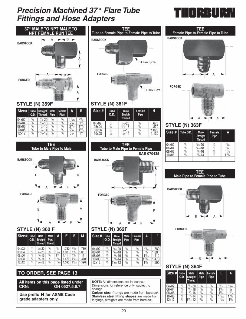
23
Size # �;1- %/5- �-8/5- '���� 3)/,>.3 �,-
�.)-/0
Precision Machined 37° Flare TubeFittings and Hose Adapters
Size # �;1-����� %/5- �-8/5- �3)/,>.3� �,-�.)-/0
STYLE (N) 363F
TEEFemale Pipe to Female Pipe to Tube
��$�� ��� ������� ��� �������$�� ��� ������� ��� �����$�� ��� ������ ��� �������$�� ��� ������ ��� ������
AA
AA
STYLE (N) 364F
TEEMale Pipe to Female Pipe to Tube
��$�� ��� ������� ��� ��� ����� �������$�� ��� ������� ��� ��� ����� �����$�� ��� ������ ��� ��� ����� �������$�� ��� ������ ��� ��� ������ ��������$�� ��� �������� ��� ��� ������ ����
Size # �;1- %/5- %/5- �-8/5- � ����� 3)/,>.3 �,- �,-
�.)-/0
A
A
STYLE (N) 362F
TEETube to Male Pipe to Female Pipe
SAE 070435
��$�� ��� ������� ��� ��� ����� ������$�� ��� ������� ��� ��� ��� ������$�� ��� ������ ��� ��� ����� �������$�� ��� ������ ��� ��� ������ �������$�� ��� �������� ��� ��� ���� �����
Size# �;1- %/5- %/5- �-8/5- � ����� 3)/,>.3 �,- �,-
�.)-/0
FA
F
STYLE (N) 360 F
TEETube to Male Pipe to Male
��$�� ��� ������� ��� ����� ���� ����� ������$�� ��� ������� ��� ����� ���� ����� ������$�� ��� ������ ��� ���� ���� ����� ������$�� ��� ������ ��� ������ ����� ������ �������$�� ��� �������� ��� ������ ����� ������ �����
Size# �;1- %/5- %/5- A F E M���� 3)/,>.3 �,-
�.)-/0 �.)-/0
FA
ME
37° MALE TO NPT MALE TO NPT FEMALE RUN TEE
STYLE (N) 359F
��$�� ��� ������� ��� ��� ������ �������$�� ��� ������� ��� ��� ���� ������$�� ��� ������ ��� ��� ����� ��������$�� ��� ������ ��� ��� ���� ��������$�� ��� �������� ��� ��� ���� ����
Size# �;1- 3)/,>.3 %/5- �-8/5- A B���� �.)-/0 �,- �,-
A
A
H Hex Size
B
A
A
B
STYLE (N) 361F
TEETube to Female Pipe to Female Pipe to Tube
��$�� ��� ������� ��� ������$�� ��� ������� ��� ������$�� ��� ������ ��� �������$�� ��� ������ ��� �����
FA
ME
FA
F
H Hex Size
E
E
$�����&
������
$�����&
������
$�����&
������
$�����&
������
$�����&
������
$�����&������
NOTE: All dimensions are in inches.Dimensions for reference only, subject tochange.Carbon steel fittings are made from barstock.Stainless steel fitting shapes are made fromforgings, straights are made from barstock.
TO ORDER, SEE PAGE 13
All items on this page listed underCRN: OH 0527.5.6.7
Use prefix � for ASME Codegrade adapters only.
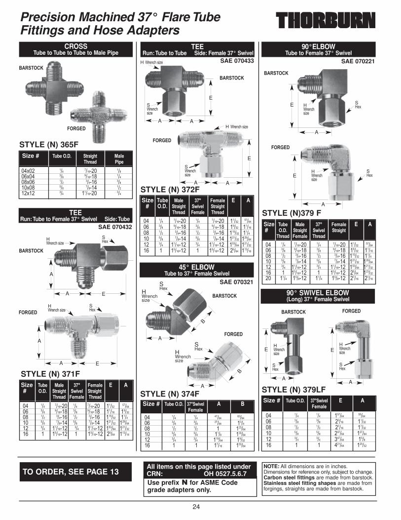
24
Precision Machined 37° Flare TubeFittings and Hose Adapters
Size �;1- %/5- ��� �-8/5- � �# ���� 3)/,>.3 9,2-5 3)/,>.3
�.)-/0 �-8/5- �.)-/0
SAE 070432
STYLE (N) 371F
TEERun:Tube to Female 37° Swivel Side:Tube
�� ��� ������� ��� ������� ����� ������� ��� ������� ��� ������� ����� ������� ��� ������ ��� ������ ������ ������ ��� ������ ��� ������ ������ �������� ��� �������� ����������������������� ������ �������� � �������� ���������������� ����� ������
H?���,��'�6�
S=�$
A
EA
H?���,��'�6�
S=�$
A
EA
SAE 070433
STYLE (N) 372F
TEERun: Tube to Tube Side: Female 37° Swivel
�� ��� ������� ��� ������� ����� ������� ��� ������� ��� ������� ����� ������� ��� ������ ��� ������ ������ ������ ��� ������ ��� ������ ������ �������� ��� �������� ��� �������� ������ �������� � �������� � �������� ����� ������
Size �;1- %/5- ��� �-8/5- � �# ���� 3)/,>.3 9,2-5 3)/,>.3
�.)-/0 �-8/5- �.)-/0
H ?���,��'�6�
S?���,�'�6�
AA
E
H ?���,��'�6�
S?���,�'�6�
AA
E
STYLE (N) 365F
CROSSTube to Tube to Tube to Male Pipe
��$�� ��� ������� �����$�� ��� ������� �����$�� ��� ������ �����$�� ��� ������ �����$�� ��� �������� ���
Size # �;1-����� 3)/,>.3� %/5-�.)-/0 �,-
SAE 070321
STYLE (N) 374F
45° ELBOWTube to 37° Female Swivel
�� ��� ��� ����� ������� ��� ��� ����� ������ ��� ��� � �������� ��� ��� ���� �������� ��� ��� ������ ������� � � ����� ������
Size # �;1-����� ���9,2-5� � $�-8/5-
SHex
HWrenchsize
A
B
SHex
HWrenchsize
A
B
STYLE (N) 379LF
90° SWIVEL ELBOW(Long) 37° Female Swivel
�� ��� ��� ������ ������� ��� ��� ����� ������� ��� ��� ����� ������� ��� ��� ������ �������� ��� ��� ������ ������ � � ������ ������
Size # �;1-����� ���9,2-5� � ��-8/5-
SAE 070221
STYLE (N)379 F
90°ELBOWTube to Female 37° Swivel
�� ��� ������� ��� ������� ����� ������� ��� ������� ��� ������� ����� ������� ��� ������ ��� ������ ������ ������ ��� ������ ��� ������ ������ �������� ��� �������� ��� �������� ������ �������� � �������� � �������� ����� �������� ���� ������� ���� ������� ����� �����
H?���,�'�6�
S=�$E
A
H?���,�'�6�
S=�$E
A
H?���,�'�6�
S=�$
E
A
H?���,�'�6�
S=�$
E
A
$�����&
������
$�����&
������
$�����&
������
$�����&
������
$�����&
������
$�����& ������
NOTE: All dimensions are in inches.Dimensions for reference only, subject to change.Carbon steel fittings are made from barstock.Stainless steel fitting shapes are made fromforgings, straights are made from barstock.
TO ORDER, SEE PAGE 13All items on this page listed underCRN: OH 0527.5.6.7Use prefix � for ASME Codegrade adapters only.
Size �;1- %/5- ��� �-8/5- � �# ���� 3)/,>.3 9,2-5 3)/,>.3
�.)-/0 �-8/5- �.)-/0
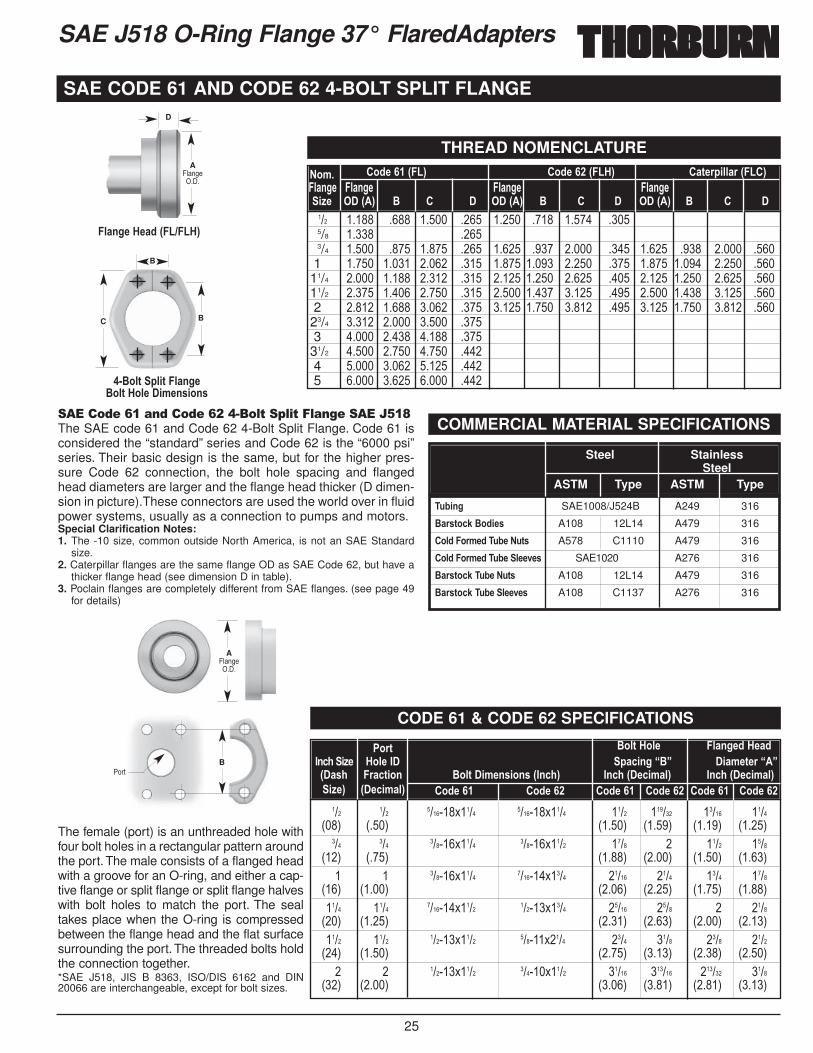
25
SAE J518 O-Ring Flange 37° FlaredAdapters
�����(�)*��(��(�)+,��� -�. �-� ��������/*0The SAE code 61 and Code 62 4-Bolt Split Flange. Code 61 isconsidered the “standard” series and Code 62 is the “6000 psi”series. Their basic design is the same, but for the higher pres-sure Code 62 connection, the bolt hole spacing and flangedhead diameters are larger and the flange head thicker (D dimen-sion in picture).These connectors are used the world over in fluidpower systems, usually as a connection to pumps and motors.Special Clarification Notes:1. The -10 size, common outside North America, is not an SAE Standard
size.2. Caterpillar flanges are the same flange OD as SAE Code 62, but have a
thicker flange head (see dimension D in table).3. Poclain flanges are completely different from SAE flanges. (see page 49
for details)
The female (port) is an unthreaded hole withfour bolt holes in a rectangular pattern aroundthe port. The male consists of a flanged headwith a groove for an O-ring, and either a cap-tive flange or split flange or split flange halveswith bolt holes to match the port. The sealtakes place when the O-ring is compressedbetween the flange head and the flat surfacesurrounding the port. The threaded bolts holdthe connection together.*SAE J518, JIS B 8363, ISO/DIS 6162 and DIN20066 are interchangeable, except for bolt sizes.
THREAD NOMENCLATURE
SAE CODE 61 AND CODE 62 4-BOLT SPLIT FLANGE
A45����� �
A45����� �
"��)
B
B
C
D
�5/+>-�'-/0�6��I��'7
� $*53�5,3��5/+>-$*53�'*5-��,8-+4,*+4
��� ����� ���� ����� ���� ����� ���� ����� ����5/8 ����� ����3/4 ����� ���� ����� ���� ����� ���� ����� ���� ����� ���� ����� ����1 ����� ����� ����� ���� ����� ����� ����� ���� ����� ����� ����� ����11/4 ����� ����� ����� ���� ����� ����� ����� ���� ����� ����� ����� ����11/2 ����� ����� ����� ���� ����� ����� ����� ���� ����� ����� ����� ����2 ����� ����� ����� ���� ����� ����� ����� ���� ����� ����� ����� ����23/4 ����� ����� ����� ����3 ����� ����� ����� ����31/2 ����� ����� ����� ����4 ����� ����� ����� ����5 ����� ����� ����� ����
�*8� �*0-����6��7 �*0-����6��'7 �/3-),55/)�6���7�5/+>- �5/+>- �5/+>- �5/+>-,=- ���6�7 $ � � ���6�7 $ � � ���6�7 $ � �
B
COMMERCIAL MATERIAL SPECIFICATIONS
�;1,+> SAE1008/J524B A249 316
$/)43*<?�$*0,-4 A108 12L14 A479 316
�*50��*)8-0��;1-��;34 A578 C1110 A479 316
�*50��*)8-0��;1-�5--2-4 SAE1020 A276 316
$/)43*<?��;1-��;34 A108 12L14 A479 316
$/)43*<?��;1-�5--2-4 A108 C1137 A276 316
Steel Stainless Steel
ASTM Type ASTM Type
CODE 61 & CODE 62 SPECIFICATIONS
��� ��� �������$���� �������$���� ���� ������ ����� ����1��3 1���3 1����3 1����3 1����3 1����3
��� ��� ������$���� ������$���� ���� � ���� ����1��3 1���3 1����3 1����3 1����3 1����3� � ������$���� �������$���� ����� ���� ���� ����
1��3 1����3 1����3 1����3 1����3 1����3���� ���� �������$���� ������$���� ����� ���� � ����1��3 1����3 1����3 1����3 1����3 1����3���� ���� ������$���� ������$���� ���� ���� ���� ����1��3 1����3 1����3 1����3 1����3 1����3� � ������$���� ������$���� ����� ������ ������ ����
1��3 1����3 1����3 1����3 1����3 1����3
�*)3� $*53�'*5- �5/+>-0�'-/0�+<.�,=- '*5-��� /<,+>��$� �,/8-3-)����6�/4. �)/<3,*+ $*53��,8-+4,*+4�6�+<.7 �+<.�6�-<,8/57 �+<.�6�-<,8/57,=-7 6�-<,8/57 �*0-��� �*0-��� �*0-��� �*0-��� �*0-��� �*0-���
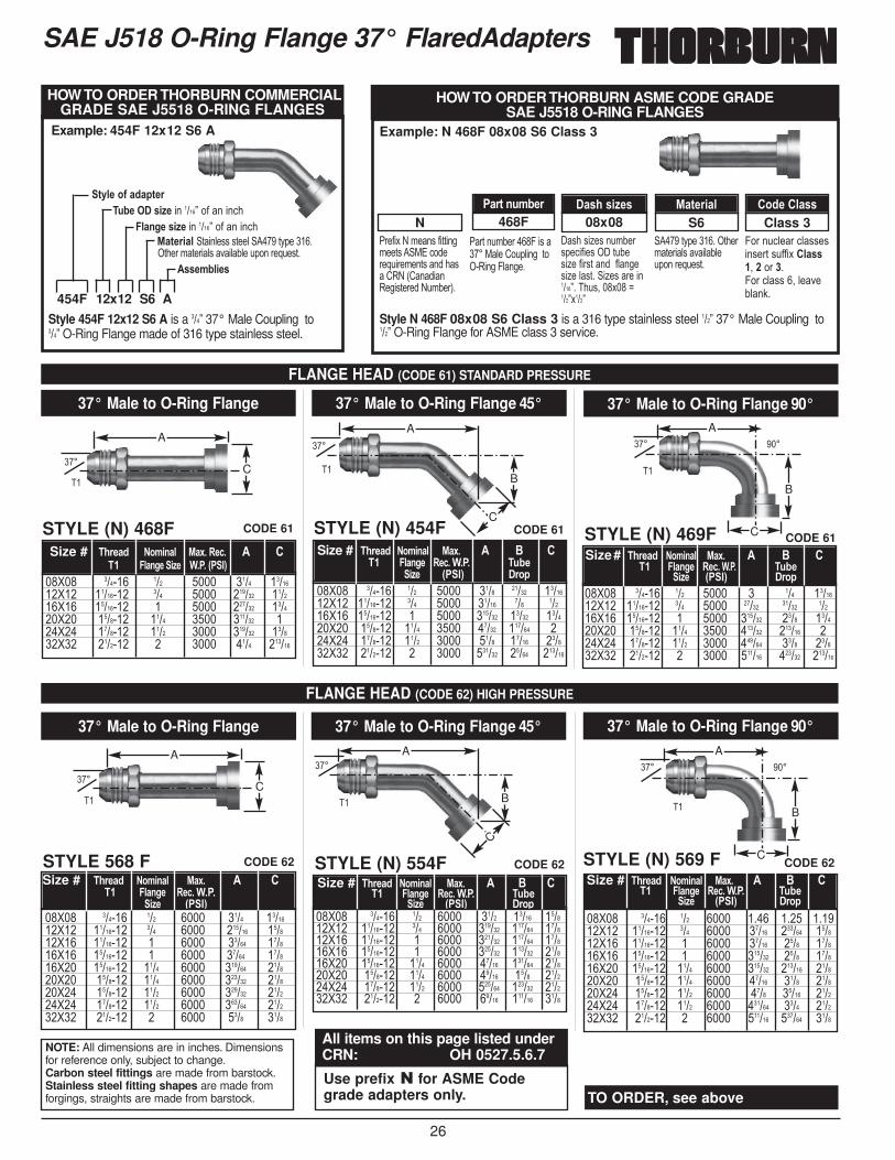
26
Size # �.)-/0 �*8,+/5 %/F���-<�� � ��� �5/+>-�,=- �����6��7
���
������
�� ��
SAE J518 O-Ring Flange 37° FlaredAdapters
FLANGE HEAD (CODE 61) STANDARD PRESSURE
FLANGE HEAD (CODE 62) HIGH PRESSURE
37° Male to O-Ring Flange
STYLE (N) 468F CODE 61
CODE 62
CODE 61
CODE 62
CODE 61
CODE 62
37° Male to O-Ring Flange 45°
STYLE (N) 454F
37° Male to O-Ring Flange 90°
STYLE (N) 469F
37° Male to O-Ring Flange
STYLE 568 F
37° Male to O-Ring Flange 45°
STYLE (N) 554F
37° Male to O-Ring Flange 90°
STYLE (N) 569 F
��>�� ������ ��� ���� ���� ����� �������>�� �������� ��� ���� ����� ��� �����>�� �������� � ���� ������ ����� ������>�� ������� ���� ���� ����� ������ ���>�� ������� ���� ���� ���� ����� ������>�� ������� � ���� ������ ����� ������
Size # �.)-/0 �*8,+/5 %/F�� � $ ��� �5/+>- �-<������ �;1-
,=- 6��7 �)*
��>�� ������ ��� ���� ���� �������>�� �������� ��� ���� ������ ������>�� �������� � ���� ����� ������>�� �������� � ���� ����� ������>�� �������� ���� ���� ������ ������>�� ������� ���� ���� ������ ������>�� ������� ���� ���� ������ ������>�� ������� ���� ���� ������ ������>�� ������� � ���� ���� ����
Size # �.)-/0 �*8,+/5 %/F�� � ��� �5/+>-� �-<�������
,=- 6��7
��>�� ������ ��� ���� � ��� �������>�� �������� ��� ���� ����� ����� �����>�� �������� � ���� ������ ���� ������>�� ������� ���� ���� ������ ������ ���>�� ������� ���� ���� ������ ���� ������>�� ������� � ���� ������ ������ ������
Size# �.)-/0 �*8,+/5 %/F�� � $ ��� �5/+>-� �-<� ����� �;1-
,=- 6��7 �)*
��>�� ������ ��� ���� ���� ����� ������>�� �������� ��� ���� ������ ������ ������>�� �������� � ���� ������ ������ ������>�� �������� � ���� ������ ������ ������>�� �������� ���� ���� ����� ������ ������>�� ������� ���� ���� ����� ���� ������>�� ������� ���� ���� ������ ������ ������>�� ������� � ���� ����� ������ ����
Size # �.)-/0 �*8,+/5 %/F�� � $ ��� �5/+>-� �-<����� �;1-
,=- 6��7 �)*��>�� ������ ��� ���� ���� ���� ������>�� �������� ��� ���� ����� ������ ������>�� �������� � ���� ����� ���� ������>�� �������� � ���� ������ ���� ������>�� �������� ���� ���� ������ ������ ������>�� ������� ���� ���� ����� ���� ������>�� ������� ���� ���� ���� ����� ������>�� ������� ���� ���� ������ ���� ������>�� ������� � ���� ������ ������ ����
Size # �.)-/0 �*8,+/5 %/F�� � $ ��� �5/+>-� �-<����� �;1-
,=- 6��7 �)*
��>�� ������ ��� ���� ���� �������>�� �������� ��� ���� ������ ������>�� �������� � ���� ������ ������>�� ������� ���� ���� ������ ���>�� ������� ���� ���� ������ ������>�� ������� � ���� ���� ������
A
C
���
A
C
���A
C
B
���A
C
B
��� ���A
C
B
��� ���A
C
B
NOTE: All dimensions are in inches. Dimensionsfor reference only, subject to change.Carbon steel fittings are made from barstock.Stainless steel fitting shapes are made fromforgings, straights are made from barstock.
All items on this page listed underCRN: OH 0527.5.6.7
Use prefix � for ASME Codegrade adapters only. TO ORDER, see above
Style 454F 12x12 S6 A is a ���7�37° Male Coupling to ���7�O-Ring Flange made of 316 type stainless steel.
3D5-�*E�/0/3-)�;1-����4,=-��� ����7��#�����,�
�5/+>-�4,=-��� ����7��#�����,�%/3-),/5� )��5�''�')��5� �����)D(��������)����&)���5'���525��.(�����-.�')�
�44-815,-4
HOW TO ORDER THORBURN COMMERCIALGRADE SAE J5518 O-RING FLANGES
HOW TO ORDER THORBURN ASME CODE GRADE SAE J5518 O-RING FLANGES
Example: 454F 12x12 S6 A Example: N 468F 08x08 S6 Class 3
Style N 468F 08x08 S6 Class 3 is a 316 type stainless steel ���7�37° Male Coupling to���7�O-Ring Flange for ASME class 3 service.
"��#�$�%�&��'�#�))���&��)'�� *+�,����-.���&��)'����'�/0%�1/���0���')����%.&2��3�
"�)��.&2������4��'�����*5��/�.(5�����)���0����45����
'��'�6�'��.&2��'(�,�#��'�� �).2�'�6��#��')����#5���'�6��5')�� �6�'����������7����.'!���$���8���7$���7
�����)D(��������)���&)���5'���525�.(�����-.�')�
4����.,5���,5''�'��'��)�'.##�$ �5/44��!�� ������4���,5''��!�5���25�:�
Class 3S608x08 468F N�/)3�+;81-) �/4.�4,=-4 %/3-),/5 �*0-��5/44
��
454F 12x12 S6 A
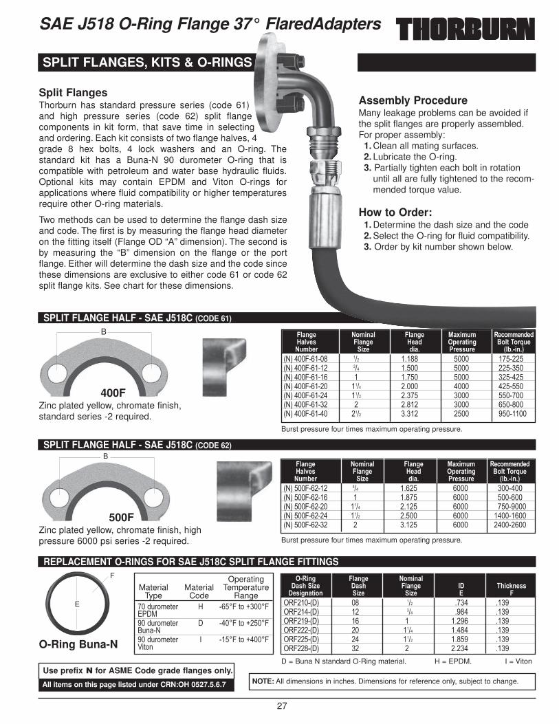
27
SAE J518 O-Ring Flange 37° FlaredAdapters
SPLIT FLANGES, KITS & O-RINGS
SPLIT FLANGE HALF - SAE J518C (CODE 61)
1%3����4������ ��� ����� ���� �������1%3����4������ ��� ����� ���� �������1%3����4������ � ����� ���� �������1%3����4������ ���� ����� ���� �������1%3����4������ ���� ����� ���� �������1%3����4������ � ����� ���� �������1%3����4������ ���� ����� ���� ��������
�5/+>- �*8,+/5 �5/+>- %/F,8;8 �-<*88-+0-0'/52-4 �5/+>-� '-/0� �-)/3,+> $*53��*)J;-�;81-) ,=- 0,/� �)-44;)- 651� ,+�7
400FZinc plated yellow, chromate finish,standard series -2 required.
SPLIT FLANGE HALF - SAE J518C (CODE 62)
1%3����4������ ��� ����� ���� �������1%3����4������ � ����� ���� �������1%3����4������ ���� ����� ���� ��������1%3����4������ ���� ����� ���� ���������1%3����4������ � ����� ���� ���������
�5/+>- �*8,+/5 �5/+>- %/F,8;8 �-<*88-+0-0'/52-4 �5/+>-� '-/0� �-)/3,+> $*53��*)J;-�;81-) ,=- 0,/� �)-44;)- 651� ,+�7
500FZinc plated yellow, chromate finish, highpressure 6000 psi series -2 required.
OperatingMaterial Material Temperature
Type Code Range���.��&�)�� = ����4�)��H����4+" *���.��&�)�� ����4�)��H����4�.��%���.��&�)�� � ����4�)��H����4C�)��
REPLACEMENT O-RINGS FOR SAE J518C SPLIT FLANGE FITTINGS
�04����1 3 �� ��� ���� �����04����1 3 �� ��� ���� �����04����1 3 �� � ����� �����04����1 3 �� ���� ����� �����04����1 3 �� ���� ����� �����04����1 3 �� � ����� ����
� �,+> �5/+>- �*8,+/5�/4.�,=- �/4. �5/+>- �� �.,<?+-44�-4,>+/3,*+ ,=- ,=- � �
O-Ring Buna-N
Split FlangesThorburn has standard pressure series (code 61)and high pressure series (code 62) split flangecomponents in kit form, that save time in selectingand ordering. Each kit consists of two flange halves, 4grade 8 hex bolts, 4 lock washers and an O-ring. Thestandard kit has a Buna-N 90 durometer O-ring that iscompatible with petroleum and water base hydraulic fluids.Optional kits may contain EPDM and Viton O-rings forapplications where fluid compatibility or higher temperaturesrequire other O-ring materials.
Two methods can be used to determine the flange dash sizeand code. The first is by measuring the flange head diameteron the fitting itself (Flange OD “A” dimension). The second isby measuring the “B” dimension on the flange or the portflange. Either will determine the dash size and the code sincethese dimensions are exclusive to either code 61 or code 62split flange kits. See chart for these dimensions.
Assembly ProcedureMany leakage problems can be avoided ifthe split flanges are properly assembled.For proper assembly:
1. Clean all mating surfaces.2. Lubricate the O-ring.3. Partially tighten each bolt in rotation
until all are fully tightened to the recom-mended torque value.
How to Order:1. Determine the dash size and the code2. Select the O-ring for fluid compatibility.3. Order by kit number shown below.
B
B
F
E
D = Buna N standard O-Ring material. H = EPDM. I = Viton
NOTE: All dimensions in inches. Dimensions for reference only, subject to change.All items on this page listed under CRN:OH 0527.5.6.7
Use prefix � for ASME Code grade flanges only.
Burst pressure four times maximum operating pressure.
Burst pressure four times maximum operating pressure.
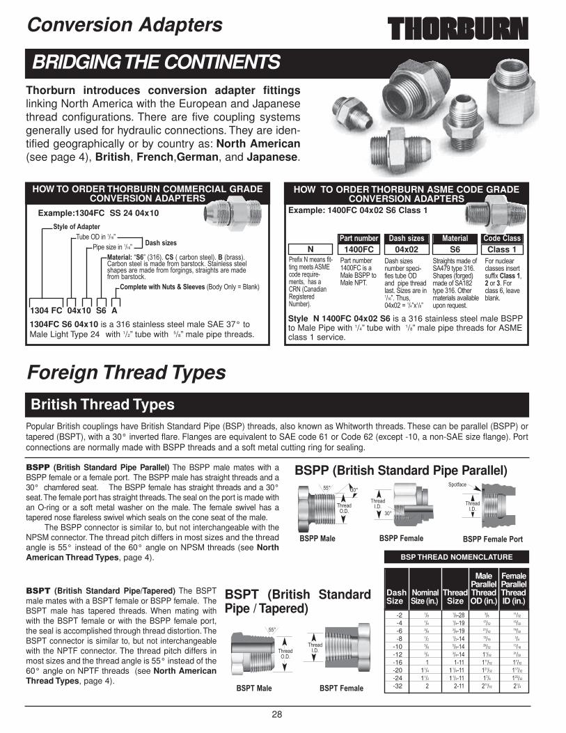
28
���� (British Standard Pipe Parallel) The BSPP male mates with aBSPP female or a female port. The BSPP male has straight threads and a30° chamfered seat. The BSPP female has straight threads and a 30°seat.The female port has straight threads.The seal on the port is made withan O-ring or a soft metal washer on the male. The female swivel has atapered nose flareless swivel which seals on the cone seat of the male.
The BSPP connector is similar to, but not interchangeable with theNPSM connector. The thread pitch differs in most sizes and the threadangle is 55° instead of the 60° angle on NPSM threads (see NorthAmerican Thread Types, page 4).
���� (British Standard Pipe/Tapered) The BSPTmale mates with a BSPT female or BSPP female. TheBSPT male has tapered threads. When mating withwith the BSPT female or with the BSPP female port,the seal is accomplished through thread distortion. TheBSPT connector is similar to, but not interchangeablewith the NPTF connector. The thread pitch differs inmost sizes and the thread angle is 55° instead of the60° angle on NPTF threads (see North AmericanThread Types, page 4).
British Thread Types
Foreign Thread Types
-2 ��� ������ ��� �����-4 ��� ������ ����� �����-6 ��� ������ ����� �����-8 ��� ������ ����� ���
-10 ��� ������ ����� �����-12 ��� ������ ����� �����-16 � ���� ������ �����-20 1��� 1������ ������ ������-24 1��� 1������ ���� ������-32 � ���� ������ ����
Male FemaleParallel Parallel
Dash Nominal Thread Thread ThreadSize Size (in.) Size OD (in.) ID (in.)
$�� %/5- $�� �-8/5- $�� �-8/5-��*)3
���
������ � ����
�� �
(�)#,�
������ �
���
���
$���%/5-
���
������ �
$����-8/5-
������ �
Popular British couplings have British Standard Pipe (BSP) threads, also known as Whitworth threads. These can be parallel (BSPP) ortapered (BSPT), with a 30° inverted flare. Flanges are equivalent to SAE code 61 or Code 62 (except -10, a non-SAE size flange). Portconnections are normally made with BSPP threads and a soft metal cutting ring for sealing.
Conversion Adapters
BRIDGING THE CONTINENTS
1304FC S6 04x10 is a 316 stainless steel male SAE 37° toMale Light Type 24° with 1/2” tube with 5/8” male pipe threads.
HOW TO ORDER THORBURN COMMERCIAL GRADECONVERSION ADAPTERS
3D5-�*E��0/3-)�.2��� ��������7
"�(��'�6���������7�%/3-),/5B B�7�1���3����1�,�2���')��53��$ 12�''3��/�2���')��5��'�&��#��&�2�')�,:�� )��5�''�')��5'�(�'����&��#��&�#������'!�')����)'����&��#��&�2�')�,:�
�*85-3-�9,3.��;34�@�5--2-4 1��D���5D�8��5�:3
1304 FC 04x10 S6 A
Example:1304FC SS 24 04x10
�/4.�4,=-4
Example: 1400FC 04x02 S6 Class 1
Style N 1400FC 04x02 S6 is a 316 stainless steel male BSPPto Male Pipe with 1/4” tube with 1/8” male pipe threads for ASMEclass 1 service.
HOW TO ORDER THORBURN ASME CODE GRADECONVERSION ADAPTERS
BSP THREAD NOMENCLATURE
"��#�$�%�&��'�#�)�)����&��)'�� *+,�����-.����&��)'!���'�/0%�1/���0���')���%.&2��3�
"�)��.&2������4/��'�*5��� "" )�*5��%"��
'��'�6�'�.&2���'(�,��#��'�).2��� ���(�(��)���5')�� �6�'����������7����.'!��$���8����7$���7
)����)'�&���# �����)D(������ �(�'�1#����3&���#� ����)D(��������)���&)���5'���525�.(�����-.�')�
4����.,5��,5''�'���'��)'.##�$ �5/44��!� ������4��,5''��!�5���25�:�
Class 1S604x021400FCN�/)3�+;81-) �/4.�4,=-4 %/3-),/5 �*0-��5/44
Thorburn introduces conversion adapter fittingslinking North America with the European and Japanesethread configurations. There are five coupling systemsgenerally used for hydraulic connections. They are iden-tified geographically or by country as: North American(see page 4), British, French,German, and Japanese.
BSPP (British Standard Pipe Parallel)
BSPT (British StandardPipe / Tapered)
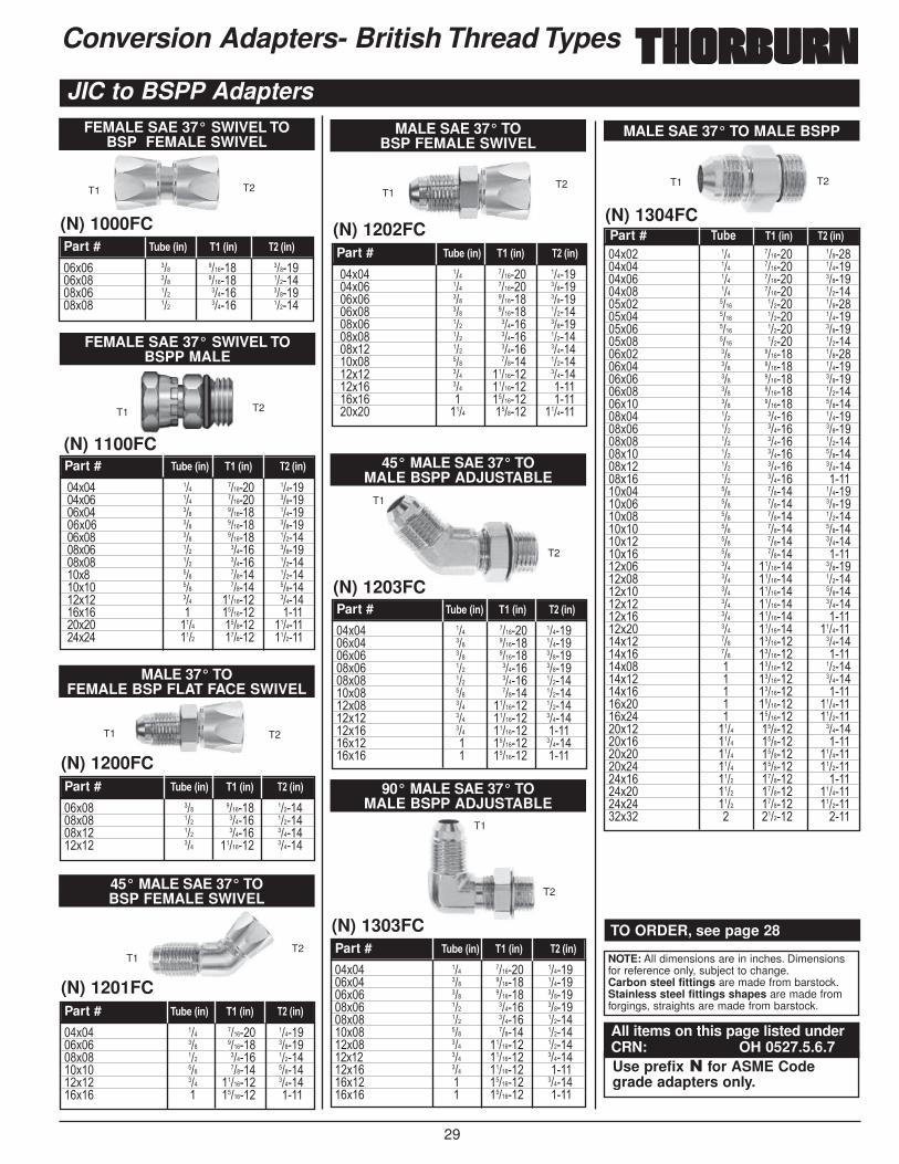
29
MALE SAE 37° TO BSP FEMALE SWIVEL
(N) 1202FC
��$�� ��� ������� ��������$�� ��� ������� ��������$�� ��� ������� ��������$�� ��� ������� ��������$�� ��� ������ ��������$�� ��� ������ ��������$�� ��� ������ ��������$�� ��� ������ ��������$�� ��� �������� ��������$�� ��� �������� ������$�� � �������� ������$�� ���� ������� �������
Part # �;1-�6,+7 ���6,+7 ���6,+7
T1T2
FEMALE SAE 37° SWIVEL TO BSPP MALE
(N) 1100FC
��$�� ��� ������� ��������$�� ��� ������� ��������$�� ��� ������� ��������$�� ��� ������� ��������$�� ��� ������� ��������$�� ��� ������ ��������$�� ��� ������ ��������$� ��� ������ ��������$�� ��� ������ ��������$�� ��� �������� ��������$�� � �������� ������$�� ���� ������� ���������$�� ���� ������� �������
Part # �;1-�6,+7 ���6,+7 ���6,+7
T1 T2
Conversion Adapters- British Thread Types
JIC to BSPP Adapters
(N) 1000FC
��$�� ��� ������� ��������$�� ��� ������� ��������$�� ��� ������ ��������$�� ��� ������ ������
Part # �;1-�6,+7 ���6,+7 ���6,+7
T1 T2
MALE 37° TO FEMALE BSP FLAT FACE SWIVEL
(N) 1200FC
��$�� ��� ������� ��������$�� ��� ������ ��������$�� ��� ������ ��������$�� ��� �������� ������
Part # �;1-�6,+7 ���6,+7 ���6,+7
T1 T2
45° MALE SAE 37° TO BSP FEMALE SWIVEL
(N) 1201FC
��$�� ��� ������� ��������$�� ��� ������� ��������$�� ��� ������ ��������$�� ��� ������ ��������$�� ��� �������� ��������$�� � �������� ����
Part # �;1-�6,+7 ���6,+7 ���6,+7
T1T2
NOTE: All dimensions are in inches. Dimensionsfor reference only, subject to change.Carbon steel fittings are made from barstock.Stainless steel fittings shapes are made fromforgings, straights are made from barstock.
Use prefix � for ASME Codegrade adapters only.
TO ORDER, see page 28
All items on this page listed underCRN: OH 0527.5.6.7
FEMALE SAE 37° SWIVEL TO BSP FEMALE SWIVEL
MALE SAE 37° TO MALE BSPP
(N) 1304FC
��$�� ��� ������� ��������$�� ��� ������� ��������$�� ��� ������� ��������$�� ��� ������� ��������$�� ���� ������ ��������$�� ���� ������ ��������$�� ���� ������ ��������$�� ���� ������ ��������$�� ��� ������� ��������$�� ��� ������� ��������$�� ��� ������� ��������$�� ��� ������� ��������$�� ��� ������� ��������$�� ��� ������ ��������$�� ��� ������ ��������$�� ��� ������ ��������$�� ��� ������ ��������$�� ��� ������ ��������$�� ��� ������ ������$�� ��� ������ ��������$�� ��� ������ ��������$�� ��� ������ ��������$�� ��� ������ ��������$�� ��� ������ ��������$�� ��� ������ ������$�� ��� �������� ��������$�� ��� �������� ��������$�� ��� �������� ��������$�� ��� �������� ��������$�� ��� �������� ������$�� ��� �������� ���������$�� ��� �������� ��������$�� ��� �������� ������$�� � �������� ��������$�� � �������� ��������$�� � �������� ������$�� � �������� ���������$�� � �������� ���������$�� ���� ������� ��������$�� ���� ������� ������$�� ���� ������� ���������$�� ���� ������� ���������$�� ���� ������� ������$�� ���� ������� ���������$�� ���� ������� ���������$�� � ������� ����
Part # �;1- ���6,+7 ���6,+7
T1 T2
45° MALE SAE 37° TO MALE BSPP ADJUSTABLE
(N) 1203FC
��$�� ��� ������� ��������$�� ��� ������� ��������$�� ��� ������� ��������$�� ��� ������ ��������$�� ��� ������ ��������$�� ��� ������ ��������$�� ��� �������� ��������$�� ��� �������� ��������$�� ��� �������� ������$�� � �������� ��������$�� � �������� ����
Part # �;1-�6,+7 ���6,+7 ���6,+7
T1
T2
90° MALE SAE 37° TO MALE BSPP ADJUSTABLE
(N) 1303FC
��$�� ��� ������� ��������$�� ��� ������� ��������$�� ��� ������� ��������$�� ��� ������ ��������$�� ��� ������ ��������$�� ��� ������ ��������$�� ��� �������� ��������$�� ��� �������� ��������$�� ��� �������� ������$�� � �������� ��������$�� � �������� ����
Part # �;1-�6,+7 ���6,+7 ���6,+7
T1
T2
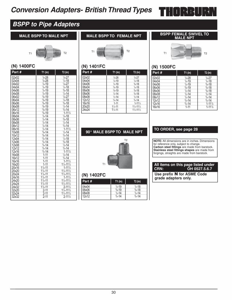
30
Conversion Adapters- British Thread Types
BSPP to Pipe Adapters
��$�� ������ ��������$�� ������ ��������$�� ������ ��������$�� ������ ��������$�� ������ ��������$�� ������ ��������$�� ������ ��������$�� ������ ��������$�� ������ ��������$�� ������ ��������$�� ������ ��������$�� ������ ���������$�� ������ ��������$�� ������ ��������$�� ������ ��������$�� ������ ��������$�� ������ ���������$�� ������ ��������$�� ������ ��������$�� ������ ��������$�� ������ ��������$�� ������ ��������$�� ������ ��������$�� ������ ���������$�� ���� ��������$�� ���� ��������$�� ���� ���������$�� ���� ������������$�� ������� ���������$�� ������� ������������$�� ������� ������������$�� ������� ���������$�� ������� ������������$�� ������� ������������$�� ������� ���������$�� ���� ������������$�� ���� ������������$�� ���� �������
MALE BSPP TO MALE NPT
(N) 1400FCPart # ���6,+7 ���6,+7
T1 T2
��$�� ������ ��������$�� ������ ��������$�� ������ ��������$�� ������ ��������$�� ������ ��������$�� ������ ��������$�� ������ ��������$�� ������ ��������$�� ���� ���������$�� ������� ������������$�� ������� ����������
MALE BSPP TO FEMALE NPT
(N) 1401FCPart # ���6,+7 ���6,+7
T1 T2
��$�� ������ ��������$�� ������ ��������$�� ������ ��������$�� ������ ��������$�� ������ ��������$�� ������ ��������$�� ������ ��������$�� ������ ��������$�� ������ ���������$�� ���� �������
BSPP FEMALE SWIVEL TO MALE NPT
(N) 1500FCPart # ���6,+7 ���6,+7
T1 T2
��$�� ������ ��������$�� ������ ��������$�� ������ ��������$�� ������ ������
90° MALE BSPP TO MALE NPT
(N) 1402FCPart # ���6,+7 ���6,+7
T1
T2 NOTE: All dimensions are in inches. Dimensionsfor reference only, subject to change.Carbon steel fittings are made from barstock.Stainless steel fittings shapes are made fromforgings, straights are made from barstock.
Use prefix � for ASME Codegrade adapters only.
TO ORDER, see page 28
All items on this page listed underCRN: OH 0527.5.6.7
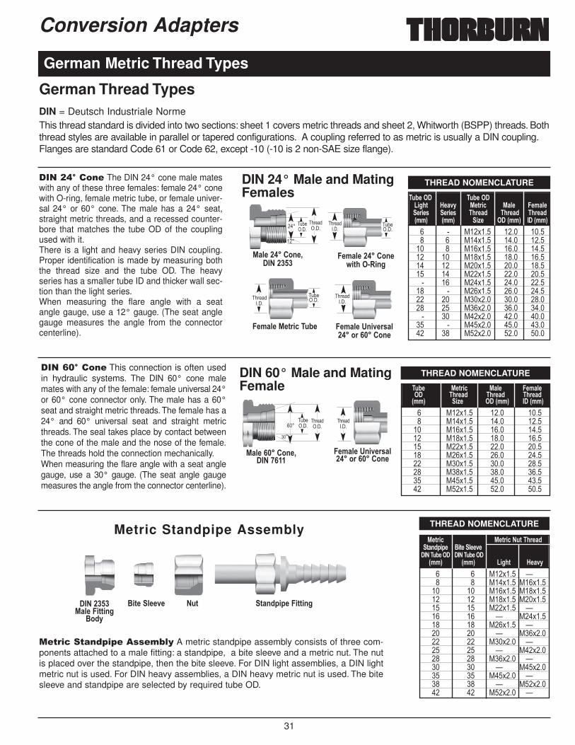
31
Conversion Adapters
1��+,����� The DIN 24° cone male mateswith any of these three females: female 24° conewith O-ring, female metric tube, or female univer-sal 24° or 60° cone. The male has a 24° seat,straight metric threads, and a recessed counter-bore that matches the tube OD of the couplingused with it.There is a light and heavy series DIN coupling.Proper identification is made by measuring boththe thread size and the tube OD. The heavyseries has a smaller tube ID and thicker wall sec-tion than the light series.When measuring the flare angle with a seatangle gauge, use a 12° gauge. (The seat anglegauge measures the angle from the connectorcenterline).
1��)2����� This connection is often usedin hydraulic systems. The DIN 60° cone malemates with any of the female: female universal 24°or 60° cone connector only. The male has a 60°seat and straight metric threads. The female has a24° and 60° universal seat and straight metricthreads. The seal takes place by contact betweenthe cone of the male and the nose of the female.The threads hold the connection mechanically.When measuring the flare angle with a seat anglegauge, use a 30° gauge. (The seat angle gaugemeasures the angle from the connector centerline).
German Metric Thread Types
THREAD NOMENCLATURE
THREAD NOMENCLATURE
� � *��$��� ���� ����� � *��$��� ���� ������ � *��$��� ���� ������ �� *��$��� ���� ������ �� *��$��� ���� ������ �� *��$��� ���� ����� �� *��$��� ���� ����
�� � *��$��� ���� ������ �� *��$��� ���� ������ �� *��$��� ���� ����� �� *��$��� ���� ����
�� � *��$��� ���� ������ �� *��$��� ���� ����
�;1-��� �;1-����,>.3� '-/2D %-3),< %/5-� �-8/5--),-4� -),-4 �.)-/0 �.)-/0 �.)-/06887 6887 ,=- ���6887 �� 6887
� *��$��� ���� ����� *��$��� ���� ������ *��$��� ���� ������ *��$��� ���� ������ *��$��� ���� ������ *��$��� ���� ������ *��$��� ���� ������ *��$��� ���� ������ *��$��� ���� ������ *��$��� ���� ����
�;1-� %-3),< %/5-� �-8/5-��� �.)-/0 �.)-/0 �.)-/06887 ,=- ���6887 ���6887
THREAD NOMENCLATURE
� � *��$��� ;� � *��$��� *��$����� �� *��$��� *��$����� �� *��$��� *��$����� �� *��$��� ;�� �� ; *��$����� �� *��$��� ;�� �� ; *��$����� �� *��$��� ;�� �� ; *��$����� �� *��$��� ;�� �� ; *��$����� �� *��$��� ;�� �� ; *��$����� �� *��$��� ;
%-3),<� %-3),<��;3��.)-/03/+0,- $,3-�5--2-�����;1-��� �����;1-���
6887 6887 �,>.3 '-/2D
%/5-������*+-C������� �
�-8/5-������*+-9,3.�� �,+>
�-8/5-�%-3),<��;1-
������ �
������ �
�.2��� �
�.2��� �
���
���
������ � �.2�
�� �
�-8/5-�#+,2-)4/5����*)������*+-
������ �
%/5-������*+-C���������
�.2��� ����
���
������ �
�-8/5-�#+,2-)4/5����*)������*+-
������ �%/5-��,33,+>
$*0D
$,3-�5--2- �;3 3/+0,-��,33,+>
Metric Standpipe Assembly
������ �
DIN = Deutsch Industriale NormeThis thread standard is divided into two sections: sheet 1 covers metric threads and sheet 2, Whitworth (BSPP) threads. Boththread styles are available in parallel or tapered configurations. A coupling referred to as metric is usually a DIN coupling.Flanges are standard Code 61 or Code 62, except -10 (-10 is 2 non-SAE size flange).
��-��3�-��(.�.�����4 5 A metric standpipe assembly consists of three com-ponents attached to a male fitting: a standpipe, a bite sleeve and a metric nut. The nutis placed over the standpipe, then the bite sleeve. For DIN light assemblies, a DIN lightmetric nut is used. For DIN heavy assemblies, a DIN heavy metric nut is used. The bitesleeve and standpipe are selected by required tube OD.
DIN 24° Male and MatingFemales
DIN 60° Male and MatingFemale
German Thread Types
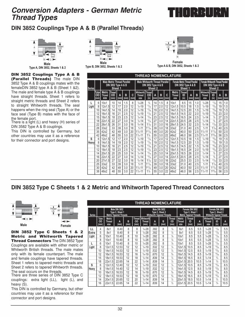
32
Conversion Adapters - German MetricThread Types
� � ��$� �� �� ��� � ������ ��� �� ��� � ��$� ��� �� ��� ������ ����� �� ����,>.3 � ��$��� �� �� ��� �� ������ ����� �� ��� �� ��$��� ���� �� ��� ������ ����� �� ���
�� ��$��� �� �� ��� �� ������ ����� �� ��� �� ��$��� ���� �� ��� ������ ����� �� ����� ��$��� �� �� ��� �� ������ ����� �� ��� �� ��$��� ���� �� ��� ������ ����� �� ����� ��$��� �� �� ��� �� ������ ����� �� ��� �� ��$��� ���� �� ��� ������ ��� �� ����� ��$��� �� �� ��� �� ������ ����� �� ��� �� ��$��� ���� �� ��� ������ ��� �� ����� ��$��� �� �� ��� �� ������ ����� �� ��� �� ��$��� ���� �� ��� ������ ����� �� ����� ��$� �� �� ��� �� ���� ������ �� ��� �� ��$� ���� �� ��� ���� ����� �� ����� ��$� �� �� ��� �� ������� ������ �� ��� �� ��$� ���� �� ��� ������� ������ �� ����� ��$� �� �� ��� �� ������� ���� �� ��� �� ��$� ���� �� ��� ������� ������ �� ���
� ��$��� �� �� ��� �� ������ ����� �� ��� �� ��$��� ���� �� ��� ������ ����� �� ���'-/2D � ��$��� �� �� ��� �� ������ ����� �� ��� �� ��$��� ���� �� ��� ������ ����� �� ���
�� ��$��� �� �� ��� �� ������ ����� �� ��� �� ��$��� ���� �� ��� ������ ����� �� ����� ��$��� �� �� ��� �� ������ ����� �� ��� �� ��$��� ���� �� ��� ������ ����� �� ����� ��$��� �� �� ��� �� ������ ����� �� ��� �� ��$��� ���� �� ��� ������ ��� �� ����� ��$��� �� �� ��� �� ������ ����� �� ��� �� ��$��� ���� �� ��� ������ ��� �� ����� ��$��� �� �� ��� �� ������ ����� �� ��� �� ��$� ���� �� ��� ������ ����� �� ����� ��$� �� �� ��� �� ���� ������ �� ��� �� ��$� ���� �� ��� ���� ����� �� ����� ��$� �� �� ��� �� ������� ������ �� ��� �� ��$� ���� �� ��� ������� ������ �� ����� ��$� �� �� ��� �� ������� ���� �� ��� �� ��$� ���� �� ��� ������� ������ �� ���
%/5-�%-3),<��.)-/0��/)/55-5 %/5-��.,39*)3.��.)-/0��/)/55-5 �-8/5-�%-3),<��.)-/0��/)/55-5 �-8/5-��.,39*)3.��.)-/0��/)/55-5�����! ���D-�� @�$ �����! ���D-�� @�$ �����! ���D-�� @�$ �����! ���D-�� @�$
-),-4 .--3�� .--3�� .--3�� .--3���;1- %-3),< �.)-/0 �.,39*)3. �.)-/0 %-3),< �.)-/0 �.,39*)3. �.)-/0�� �.)-/0 �� � $ � �.)-/0 �� � $ � �.)-/0 �� � $ �.)-/0 �� � $6887 4,=- 6887 6887 6887� 6887 4,=- 6,+7 6887 6887� 6887 4,=- 6,+7 6887� 6887 4,=- 6,+7 6887� 6887
�� � �$� ���� � � ������ ���� � ��� �$� ��� ��� ������ ����� ����F3)/ � �$� ���� � � ������ ���� � ��� �$� ��� ��� ������ ����� ����,>.3 � ��$� ����� � �� ������ ���� � ��� ��$� ��� ��� ������ ����� ���
� ��$� ����� � �� ������ ���� � ��� ��$� ��� ��� ������ ����� ���� � ��$� ����� � �� ������ ���� � ��� ��$� ��� ��� ������ ����� ���
�,>.3 � ��$��� ����� �� �� ������ ���� �� ��� ��$��� ���� ��� ������ ����� ����� ��$��� ����� �� �� ������ ���� �� ��� ��$��� ���� ��� ������ ����� ����� ��$��� ����� �� �� ������ ���� �� ��� ��$��� ���� ��� ������ ����� ����� ��$��� ����� �� �� ������ ���� �� ��� ��$��� ���� ��� ������ ��� ����� ��$��� ����� �� �� ������ ���� �� ��� ��$��� ���� ���� ������ ��� ����
� ��$��� ����� �� �� ������ ���� �� ��� ��$��� ���� ��� ������ ����� ���'-/2D � ��$��� ����� �� �� ������ ���� �� ��� ��$��� ���� ��� ������ ����� ���
�� ��$��� ����� �� �� ������ ���� �� ��� ��$��� ���� ��� ������ ����� ����� ��$��� ����� �� �� ������ ���� �� ��� ��$��� ���� ��� ������ ����� ����� ��$��� ����� �� �� ������ ���� �� ��� ��$��� ���� ���� ������ ��� ������ ��$��� ����� �� �� ������ ���� �� ��� ��$��� ���� ���� ������ ��� ����
%/5-������! �� %/5-������! � �-8/5-������! � �-8/5-������! ��D-��C�.--3�� �D-��C�.--3�� �D-��C�.--3�� �D-��C�.--3��
-),-4 %-3),<��/-)-0��.)-/04 �.,39*)3.��/-)-0��.)-/04 %-3),<��/-)-0��.)-/04 �.,39*)3.��/-)-0��.)-/04�;1- %-3),< �.)-/0 �.,39*)3. �.)-/0 %-3),< �.)-/0 �.,39*)3. �.)-/0�� �.)-/0 � $ �� �.)-/0 � $ �� �.)-/0 �� � �.)-/0 �� �6887 4,=- 6887 6887 6887� 6887 6,+7 6887 6887� 4,=- 6887� 6887 4,=- 6,+7 6887%/5- �-8/5-
� ������ �
������� � ���
��
%/5-�D-�$C������! �C�.--34���@��
%/5-�D-��C������! �C�.--34���@��
�-8/5-�D-�� @�$C������! �C�.--34���@��
� ������ ������
�� ����� �����
�� �
0��� �5
� /
4,� �5
��
/
1��0/+��!. �����5.��6������ � �����(�� The male DIN3852 Type A & B couplings mates with thefemaleDIN 3852 type A & B (Sheet 1 &2).The male and female type A & B couplingshave straight threads. Sheet 1 refers tostraight metric threads and Sheet 2 refersto straight Whitworth threads. The sealhappens when the ring seal (Type A) or theface seal (Type B) mates with the face ofthe female port.There is a light (L) and heavy (H) series ofDIN 3582 Type A & B couplings.This DIN is controlled by Germany, butother countries may use it as a referencefor their connector and port designs.
1�� 0/+ �5.� � ����-� * 6 +��-��3 ��( "��-7��-� ��.���(�����(�����3-��� The DIN 3852 TypeCouplings are available with either metric orWhitworth British threads. The male matesonly with its female counterpart. The maleand female couplings have tapered threads.Sheet 1 refers to tapered metric threads andSheet 2 refers to tapered Whitworth threads.The seal occurs on the threads.There are three series of DIN 3852 Type Ccouplings: extra light (LL), light (L), andheavy (S).This DIN is controlled by Germany, but othercountries may use it as a reference for theirconnector and port designs.
THREAD NOMENCLATURE
THREAD NOMENCLATURE
DIN 3852 Couplings Type A & B (Parallel Threads)
DIN 3852 Type C Sheets 1 & 2 Metric and Whitworth Tapered Thread Connectors
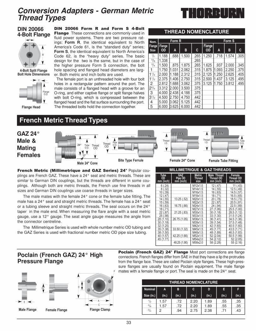
33
Conversion Adapters - German MetricThread TypesDIN 20066 4-Bolt Flange
GAZ 24°Male &MatingFemales
1�� +22)) ���4 � ��( ���4 � ,��� -� ���� These connections are commonly used influid power systems. There are two pressure rat-ings: Form R, the identical equivalent to NorthAmerica’s Code 61, is the “standard duty” series;Form S, the identical equivalent to North America’sCode 62, is the “heavy duty” series. The basicdesign for the two is the same, but in the case ofthe higher pressure Form S connection, the bolthole spacing and flanged head diameters are larg-er. Both metric and inch bolts are used.
The female port is an unthreaded hole with four boltholes in a rectangular pattern around the port. Themale consists of a flanged head with a groove for anO-ring, and either captive flange or split flange halveswith bolt O-ring, which is compressed between theflanged head and the flat surface surrounding the port.The threaded bolts hold the connection together.
THREAD NOMENCLATURE
45����� �
�
/
�5/+>-�'-/0
� $*53�5,3��5/+>-$*53�'*5-��,8-+4,*+4
��� ����� ���� ����� ���� ����� ���� ����� ����5/8 ����� ����3/4 ����� ���� ����� ���� ����� ���� ����� ����1 ����� ����� ����� ���� ����� ����� ����� ����11/4 ����� ����� ����� ���� ����� ����� ����� ����11/2 ����� ����� ����� ���� ����� ����� ����� ����2 ����� ����� ����� ���� ����� ����� ����� ����23/4 ����� ����� ����� ����3 ����� ����� ����� ����31/2 ����� ����� ����� ����4 ����� ����� ����� ����5 ����� ����� ����� ����
�*8� �*)8�� �*)8��5/+>- �5/+>- �5/+>-,=- �� � $ � �� � $ �
�
12°
%/5-������*+-
����OD
����OD24°
MILLIMETRIQUE & GAZ THREADS
THREAD NOMENCLATURE
��1���3 *��$��� ���1���3 ���1���3��1���3 *��$��� ���1���3 �����1���3���1���3 *��$��� ���1���3 �����1���3���1���3 *��$��� ���1���3 �����1���3���1���3 ������1���3 *��$��� ���1���3 �����1���3���1���3 *��$��� ���1���3 �����1���3���1���3 ������1���3 *��$��� ���1���3 �����1���3���1���3 *��$��� ���1����3 �����1����3���1���3 ������1���3 *��$��� ���1����3 �����1����3���1���3 *��$��� ���1����3 �����1����3���1����3 ������1����3 *��$��� ���1����3 �����1����3���1����3 *��$��� ���1����3 �����1����3���1����3 *��$��� ���1����3 �����1����3���1����3 ������1����3 *��$��� ���1����3 �����1����3���1����3 *��$��� ���1����3 �����1����3���1����3 ������1����3 *��$��� ���1����3 �����1����3���1����3 *��$��� ���1����3 ���1����3
������1����3 *��$��� ���1����3 ���1����3
�;1-� ��A��� %-3),< %/5-���.)-/0 �-8/5-��� �,-��� �.)-/0 �.)-/0��� �.)-/0����
88�6,+<.7 88�6,+<.7 4,=- 88�6,+<.7 88�6,+<.7
�-8/5-������*+-$,3-��D-��-));5- �-8/5-��;1-��,33,+>
������ �
������ � �.2�
�� �"�(��� ��.2�
�� �
1/2 1.57 .72 2.20 1.89 .55 .355/8 1.57 .72 2.20 1.89 .55 .353/4 2 .94 2.75 2.38 .71 .43
�*8,+/5 � $ � � � �
,=-�6,+�7 6,+�7 6,+�7 6,+�7 6,+�7 6,+�7 6,+�7
Poclain (French GAZ) 24° HighPressure Flange
%/5-��5/+>- �-8/5-��5/+>- �5/+>-��5/8
���
+
�
4
�/
����3���-��3��� �4�-��8!���(&�9�������+,� Popular cou-plings are French GAZ. These have a 24° seat and metric threads. These aresimilar to German DIN couplings, but the threads are different in some cou-plings. Although both are metric threads, the French use fine threads in allsizes and German DIN couplings use coarse threads in larger sizes.
The male mates with the female 24° cone or the female tube fitting. Themale has a 24° seat and straight metric threads. The female has a 24° seator a tubing sleeve and straight metric threads. The seal occurs on the 24°taper in the male end. When measuring the flare angle with a seat metricgauge, use a 12° gauge. The seat angle gauge measures the angle fromthe connector centreline.
The Millimetrique Series is used with whole number metric OD tubing andthe GAZ Series is used with fractional number metric OD pipe size tubing.
��3 ��������3�&�9�+,�� ����Most port connections are flangeconnections. French flanges differ from SAE in that they have a lip the protrudesfrom the flange face. These are called Poclain style flanges. These high-pres-sure flanges are usually found on Poclain equipment. The male flangemates with a female flange or port. The seal is made on the 24° seat.
French Metric Thread Types

34
��$�� � ������� *��$�����$�� � ������� *��$�����$�� � ������ *��$�����$�� � ������ *��$�����$�� � ������� *��$�����$�� � ������� *��$�����$�� � ������� *��$�����$�� � ������ *��$�����$�� � ������ *��$�����$�� �� ������ *��$�����$�� �� ������ *��$�����$�� �� �������� *��$�����$�� �� �������� *��$�����$�� �� �������� *��$���
Conversion Adapters - German Thread Types
��$�� � ������� *��$�����$�� � ������� *��$�����$�� � ������� *��$�����$�� � ������ *��$�����$�� � ������ *��$�����$�� � ������� *��$�����$�� � ������� *��$�����$�� � ������� *��$�����$�� � ������ *��$�����$�� � ������ *��$�����$�� �� ������ *��$�����$�� �� ������ *��$�����$�� �� �������� *��$�����$�� �� �������� *��$�����$�� �� �������� *��$���
MALE SAE 37° TO MALE LIGHT TYPE 24°
(N) 2000FCPart # �;1-��/4. ���6,+7 ���6887
,=-Part # �;1-��/4. ���6,+7 ���6887
,=-
Part # �;1-��/4. ���6,+7 ���6887,=-
Part # �;1-��/4. ���6,+7 ���6887,=-
T1 T2
��$�� � ������� *��$�����$�� � ������� *��$�����$�� � ������ *��$�����$�� � ������ *��$�����$�� � ������� *��$�����$�� � ������� *��$�����$�� � ������� *��$�����$�� � ������ *��$�����$�� � ������ *��$�����$�� �� ������ *��$�����$�� �� ������ *��$�����$�� �� �������� *��$�����$�� �� �������� *��$���
MALE SAE 37° TO MALE HEAVY TYPE 24°
(N) 2001FCT1 T2
MALE SAE 37° TO FEMALE LIGHT TYPE 24°
(N)2002FC
T1 T2
��$�� � ������� *��$�����$�� � ������� *��$�����$�� � ������ *��$�����$�� � ������ *��$�����$�� � ������� *��$�����$�� � ������� *��$�����$�� � ������� *��$�����$�� � ������ *��$�����$�� � ������ *��$�����$�� �� ������ *��$�����$�� �� ������ *��$�����$�� �� �������� *��$�����$�� �� �������� *��$���
MALE SAE 37° TO FEMALE HEAVY TYPE 24°
(N) 2003FC
T1 T2
��$�� ������ *��$�����$�� ������� *��$�����$�� ������� *��$�����$�� ������� *��$�����$�� ������� *��$�����$�� ������� *��$�����$�� ������ *��$�����$�� ������ *��$�����$�� ������ *��$�����$�� ������ *��$�����$�� ������ *��$�����$�� ������ *��$�����$�� ������ *��$�����$�� ������ *��$���
FEMALE SAE 37° SWIVEL TO METRIC MALE
(N) 2004FCPart # ���6,+7 ���6887
T1 T2
�� *��$����� *��$����� *��$����� *��$����� *��$����� *��$����� *��$����� *��$����� *��$����� *��$����� *��$���
BONDED SEAL FORMETRIC THREAD
(N) 2100FCPart # �.)-/0 6887
NOTE: All dimensions are in inches. Dimensionsfor reference only, subject to change.Carbon steel fittings are made from barstock.Stainless steel fittings shapes are made fromforgings, straights are made from barstock.
Use prefix � for ASME Codegrade adapters only.
TO ORDER, see page 28
All items on this page listed underCRN: OH 0527.5.6.7
JIC / Metric Adapters
Metric to NPTFAdapters
��$�� ��$���** ��������$�� ��$���** ��������$�� ��$���** ��������$�� ��$���** ��������$�� ��$���** ��������$�� ��$���** ��������$�� ��$���** ��������$�� ��$���** ��������$�� ��$���** ��������$�� ��$���** �������
MALE METRIC TO FEMALE NPTF
(N) 2200FCPart # ���6887 ���6,+7
T1 T2
Metric Adapters
��$�� ��< ��$���**��$�� ���< ��$���**��$�� ��� ��$���**��$�� ���< ��$���**
MALE METRIC PLUG
(N) 2300FCPart # �;1-�6887 ���6887
T1

35
Conversion Adapters - Japanese Thread Types
��.����� ��.���( ��.� �����(�The Japanese tapered pipe thread connectoris identical and fully interchangeable with theBSPT (tapered) connector. The Japaneseconnector does not have a 30° flare and willnot mate with the BSPP female.The threads conform to JIS B 0203, whichare the same as the BSPT threads. However,the male end does not have a 60° chamferand will only seal when the threads arecrushed together in an appropriate JIS orBSP port. The seal is made on the threads.
��.����� 2� � ��� ���� � �����(�This connector is similar to the North American37° JIC flare except for the 30° seat angle. TheJapanese 30° flare male connector mates withJapanese 30° flare female connector only. Themale and female have straight threads and a 30°seat. The seal is made on the 30° seat. Thethreads on the Japanese 30° flare connector con-form to JIS (Japanese Industrial Standards) B0202, which are the same as the BSPP threads.Both the Japanese and the British connectorshave a 30 ° seat, but they are not interchange-able, because the British seat is inverted.
-2 1/81/8-28 3/8
11/32
-4 1/41/4-19 17/32
15/32
-6 3/83/8-19 21/32
19/32
-8 1/21/2-14 13/16
3/4
-10 5/85/8-14 29/32
13/16
-12 3/43/4-14 11/32
31/32
-16 1 1-11 15/16 17/32
-20 11/4 11/4-11 121/32 117/32
-24 11/2 11/2-11 17/8 125/32
-32 2 2-11 211/32 27/32
Japanese 30° FlareParallel Threads
%/5- �-8/5-
������ �
��� ���
������ �
Japanese 30° TaperedPipe Thread
%/5- �-8/5-
������ �
����I
������ �
Komatsu Style 30° FlareParallel Threads
%/5- �-8/5-
������ �
������
������ �
Komatsu Flange Fitting
�5/+>- �5/+>-�'-/0
45����� � �
��0����J�����
-2 1/81/8-28 3/8
11/32
-4 1/41/4-19 17/32
15/32
-6 3/83/8-19 21/32
19/32
-8 1/21/2-14 13/16
3/4
-12 3/43/4-14 11/32
31/32
-16 1 1-11 15/16 17/32
-20 11/4 11/4-11 121/32 117/32
-24 11/2 11/2-11 17/8 125/32
-32 2 2-11 211/32 27/32
�*8,+/5�,=- %-3),< %/5-� �-8/5-�/4. �.)-/0 �.)-/0� �.)-/0�,=- 6,+7 6887 ,=-� ���6887 ���6887
-4 1/4 6.5 M14x1.5 14 12.5-6 3/8 9.5 M18x1.5 18 16.5-8 1/2 13 M22x1.5 22 20.5
-10 5/8 16 M24x1.5 24 22.5-12 3/4 19 M30x1.5 30 28.5-16 1 25 M33x1.5 33 31.5-20 11/4 32 M36x1.5 36 34.5-24 11/2 38 M42x1.5 42 40.5
�*8,+/5�,=-�/4. �5/+>- � $,=- 6,+7 6887 ���6,+7 6,+7 6,+7-8 1/2 12.7 1.188 .728 .984
-10* 5/8 15.9 1.345 .728 1.102-12 3/4 19.1 1.500 .846 1.220-16 1 25.4 1.750 1.122 1.496-20 11/4 31.7 2.000 1.358 1.732-24 11/2 38.0 2.375 1.750 2.125-32 2 50.8 2.812 2.225 2.559
45����� �
*10 is a non-SAE size range.
Two popular coupling styles in Japan:1. Komatsu equipment uses couplings with a 30° seat and metric fine threads. Flanges are standard Code 61 or Code 62, except-10 (-10is 2 non-SAE size flange).2. Most other Japanese equipment uses couplings with a 30° seat and BSPP (see British) threads, usually called JIS (Japanese IndustrialStandard) couplings.They are not interchangeable with British couplings, since the flare is not inverted. Flanges as per 1.
Japanese Thread Types
:�4�-�! � ���� ��--��� TheKomatsu Style flange fitting is nearly toidentical and fully interchangeable withthe SAE Code 61 flange fitting. In allsizes the O-ring dimensions are differ-ent. When replacing a Komatsu flangewith an SAE style flange, an SAE styleO-ring must always be used.
:�4�-�!�-5 �2�� ������� � �����(� Used extensively on Komatsuequipment, the Komatsu Style 30° flareparallel thread connector is identical to theJapanese 30° flare parallel thread connec-tor except for the threads. The Komatsuconnector uses metric fine threads thatconform to JIS B 0207. The Komatsu con-nector seals on the 30° flare.
�/4. �*8,+/5 �.)-/0 %/5-� �-8/5-,=- ,=-�6,+7 ,=-� �.)-/0� �.)-/0�
���6,+7 ���6,+7
%/5-� �-8/5-�/4. �*8,+/5 �.)-/0 �.)-/0� �.)-/0�,=- ,=-�6,+7 ,=- ���6,+7 ���6,+7

36
Conversion Adapters
“JIS” Adapters
�� ��$����� ��$����� ��$����� ��$����� ��$����� ��$���
KOMATSU PLUG
Part # �.)-/0 6887
T1
�� *��$����� *��$����� *��$����� *��$����� *��$����� *��$���
KOMATSU CAP
ADAPTOR MALE SAE 37° TO FEMALE KOMATSU
Part # �.)-/0 6887
T1
T1 T2
��$�� ��� ������� *��$�����$�� ��� ������� *��$�����$�� ��� ������ *��$�����$�� ��� ������ *��$�����$�� ��� �������� *��$���
CONNECTOR MALE SAE 37° TO MALE KOMATSU
(N) 4100FC(N) 4000FC
(N) 4001FC
Part # �;1- ���6,+7 ���6887
T1 T2
�� *��$����� *��$����� *��$����� *��$����� *��$����� *��$���
MALE KOMATSU UNION
(N) 4200FCPart # ��� 6887
T1 T1
��$�� ��� ������� *��$�����$�� ��� ������� *��$�����$�� ��� ������ *��$�����$�� ��� ������ *��$�����$�� ��� �������� *��$���
(N) 4300FCPart # �;1- ���6,+7 ���6887
JIS PLUG
T1
����������������������������������������
Part # ���6,+7
JIS CAP
T1
�� �������� �������� �������� �������� ������
Part # ���6,+7
��$�� ��� ������� ��������$�� ��� ������� ��������$�� ��� ������� ��������$�� ��� ������ �������
CONNECTOR MALE SAE 37° TO MALE JIS
(N) 4600FC(N) 4400FC
(N) 4500FC (N) 4700FC
Part # �;1- ���6,+7 ���6887
T1 T2
MALE JIS UNION
T1 T1
��$�� ��������$�� ��������$�� ��������$�� ��������$�� ������
Part # ���6,+7
04x02 ��� ������� ������04x04 ��� ������� ������06x06 ��� ������� ������08x08 ��� ������ ������12x12 ��� �������� ������
ADAPTOR MALE SAE 37° TO FEMALE JIS SWIVEL
(N) 4800FCPart # �;1- ���6,+7 ���6887
T1 T2
NOTE: All dimensions are in inches. Dimensionsfor reference only, subject to change.Carbon steel fittings are made from barstock.Stainless steel fittings shapes are made fromforgings, straights are made from barstock.
Use prefix � for ASME Codegrade adapters only.
TO ORDER, see page 28
All items on this page listed underCRN: OH 0527.5.6.7
“Komatsu” Adapters
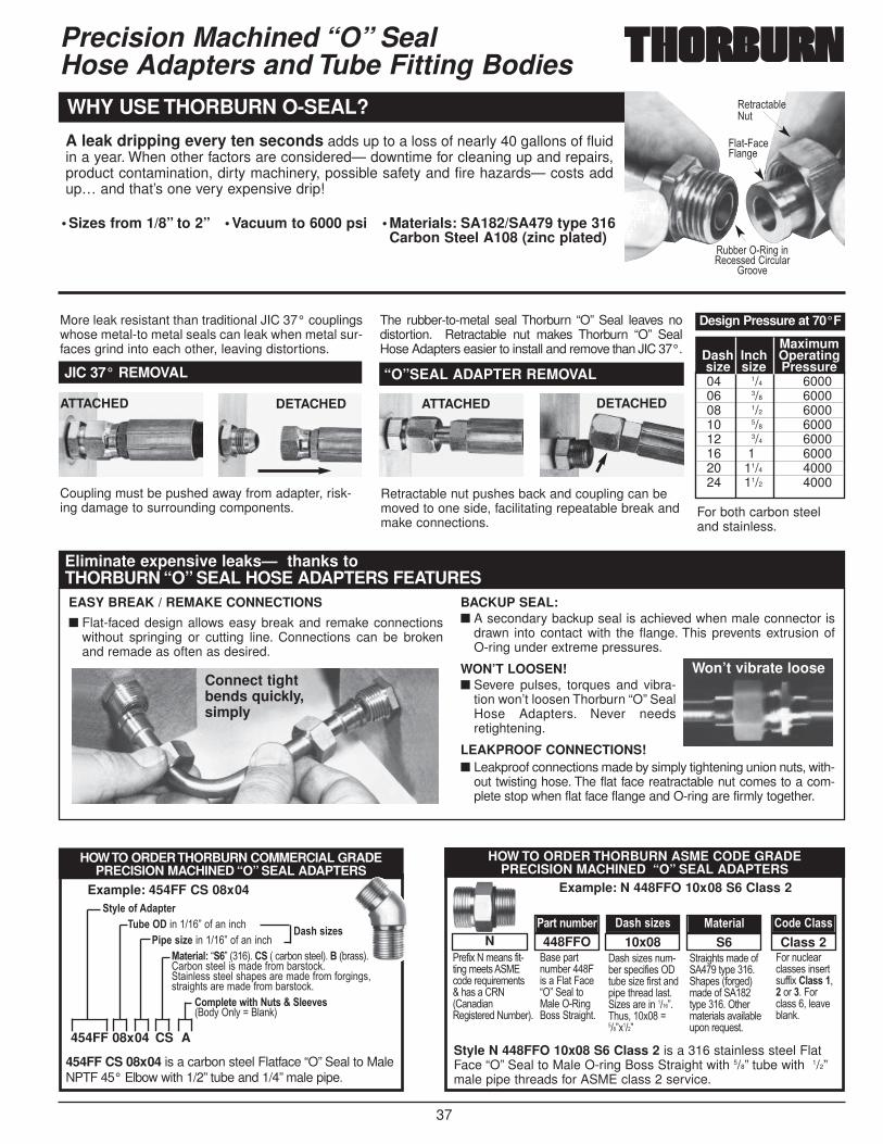
37
EASY BREAK / REMAKE CONNECTIONS
■ Flat-faced design allows easy break and remake connectionswithout springing or cutting line. Connections can be brokenand remade as often as desired.
BACKUP SEAL:■ A secondary backup seal is achieved when male connector is
drawn into contact with the flange. This prevents extrusion of O-ring under extreme pressures.
WON’T LOOSEN!■ Severe pulses, torques and vibra-
tion won’t loosen Thorburn “O” SealHose Adapters. Never needsretightening.
LEAKPROOF CONNECTIONS!■ Leakproof connections made by simply tightening union nuts, with-
out twisting hose. The flat face reatractable nut comes to a com-plete stop when flat face flange and O-ring are firmly together.
Precision Machined “O” Seal Hose Adapters and Tube Fitting Bodies
A leak dripping every ten seconds adds up to a loss of nearly 40 gallons of fluidin a year. When other factors are considered— downtime for cleaning up and repairs,product contamination, dirty machinery, possible safety and fire hazards— costs addup… and that’s one very expensive drip!
WHY USE THORBURN O-SEAL?
ATTACHED
Coupling must be pushed away from adapter, risk-ing damage to surrounding components. For both carbon steel
and stainless.
Retractable nut pushes back and coupling can bemoved to one side, facilitating repeatable break andmake connections.
DETACHED ATTACHED DETACHED
JIC 37° REMOVAL “O”SEAL ADAPTER REMOVAL
More leak resistant than traditional JIC 37° couplingswhose metal-to metal seals can leak when metal sur-faces grind into each other, leaving distortions.
The rubber-to-metal seal Thorburn “O” Seal leaves nodistortion. Retractable nut makes Thorburn “O” SealHose Adapters easier to install and remove than JIC 37°.
Eliminate expensive leaks— thanks to THORBURN “O” SEAL HOSE ADAPTERS FEATURES
454FF CS 08x04 is a carbon steel Flatface “O” Seal to MaleNPTF 45° Elbow with 1/2” tube and 1/4” male pipe.
HOW TO ORDER THORBURN COMMERCIAL GRADEPRECISION MACHINED “O” SEAL ADAPTERS
3D5-�*E��0/3-)�;1-�����������7��#�����,�
�,-�4,=- �������7��#�����,�%/3-),/5B B�7�1���3����1�,�2���')��53��$ 12�''3�/�2���')��5��'�&��#��&�2�')�,:�� )��5�''�')��5�'�(�'����&��#��&�#������'!')����)'����&��#��&�2�')�,:�
�*85-3-�9,3.��;34�@�5--2-41��D���5D�8��5�:3
Example: 454FF CS 08x04
�/4.�4,=-4
Style N 448FFO 10x08 S6 Class 2 is a 316 stainless steel FlatFace “O” Seal to Male O-ring Boss Straight with 5/8” tube with 1/2”male pipe threads for ASME class 2 service.
HOW TO ORDER THORBURN ASME CODE GRADE PRECISION MACHINED “O” SEAL ADAPTERS
"��#�$�%�&��'�#�)�)����&��)'�� *+,�����-.���&��)'K��'��/0%1/���0���')����%.&2��3�
�'��(�)�.&2������4�'��45)�4,�B�7� �5�)�*5����0�����''� )����)�
'��'�6�'��.&�2���'(�,�#��'�� ).2��'�6��#��')��(�(��)����5')� �6�'�����������7���.'!���$���8���7$���7
)����)'�&���# �����)D(������ �(�'�1#����3&���#� ����)D(��������)���&)���5'���525�.(�����-.�')�
4����.,5��,5''�'���'��)'.##�$ �5/44��!� ������4��,5''��!�5���25�:�
Class 2S610x08448FFON�/)3�+;81-) �/4.�4,=-4 %/3-),/5 �*0-��5/44
Example: N 448FFO 10x08 S6 Class 2
• Sizes from 1/8” to 2” • Vacuum to 6000 psi • Materials: SA182/SA479 type 316Carbon Steel A108 (zinc plated)
04 1/4 600006 3/8 600008 1/2 600010 5/8 600012 3/4 600016 1 600020 11/4 400024 11/2 4000
Maximum Dash Inch Operating size size Pressure
Design Pressure at 70°F
0�)�,)25�%.)
45)�4,�45���
0.22�����0������0�,�''��/��,.5�
J�����
Connect tightbends quickly,simply
Won’t vibrate loose
454FF 08x04 CS A
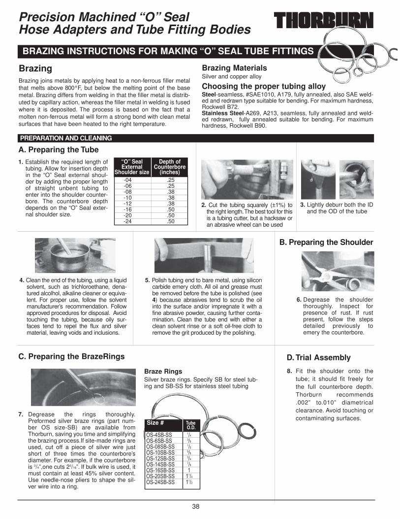
38
Precision Machined “O” Seal Hose Adapters and Tube Fitting Bodies
BrazingBrazing joins metals by applying heat to a non-ferrous filler metalthat melts above 800°F, but below the melting point of the basemetal. Brazing differs from welding in that the filler metal is distrib-uted by capillary action, whereas the filler metal in welding is fusedwhere it is deposited. The process is based on the fact that amolten non-ferrous metal will form a strong bond with clean metalsurfaces that have been heated to the right temperature.
Brazing MaterialsSilver and copper alloy
Choosing the proper tubing alloySteel-seamless, #SAE1010, A179, fully annealed, also SAE weld-ed and redrawn type suitable for bending. For maximum hardness,Rockwell B72.Stainless Steel-A269, A213, seamless, fully annealed and weld-ed redrawn, fully annealed suitable for bending. For maximumhardness, Rockwell B90.
1. Establish the required length oftubing. Allow for insertion depthin the “O” Seal external shoul-der by adding the proper lengthof straight unbent tubing toenter into the shoulder counter-bore. The counterbore depthdepends on the “O” Seal exter-nal shoulder size.
4. Clean the end of the tubing, using a liquidsolvent, such as trichloroethane, dena-tured alcolhol, alkaline cleaner or equiva-lent. For proper use, follow the solventmanufacturer’s recommendation. Followapproved procedures for disposal. Avoidtouching the tubing, because oily sur-faces tend to repel the flux and silvermaterial, leaving voids and inclusions.
5. Polish tubing end to bare metal, using siliconcarbide emery cloth. All oil and grease mustbe removed before the tube is polished (see4) because abrasives tend to scrub the oilinto the surface and/or impregnate it with afine abrasive powder, causing further conta-mination. Clean the tube end with either aclean solvent rinse or a soft oil-free cloth toremove the grit produced by the polishing.
2. Cut the tubing squarely (±1%) tothe right length.The best tool for thisis a tubing cutter, but a hacksaw oran abrasive wheel can be used
3. Lightly deburr both the IDand the OD of the tube
6. Degrease the shoulderthoroughly. Inspect forpresence of rust. If rustpresent, follow the stepsdetailed previously toemery the counterbore.
8. Fit the shoulder onto thetube; it should fit freely forthe full counterbore depth.Thorburn recommends.002” to.010” diametricalclearance. Avoid touching orcontaminating surfaces.
7. Degrease the rings thoroughly.Preformed silver braze rings (part num-ber OS size-SB) are available fromThorburn, saving you time and simplifyingthe brazing process.If site-made rings areused, cut off a piece of silver wire justshort of three times the counterbore’sdiameter. For example, if the counterboreis 3/4”,one cuts 23/16”. If bulk wire is used, itmust contain at least 45% silver content.Use needle-nose pliers to shape the sil-ver wire into a ring.
BRAZING INSTRUCTIONS FOR MAKING “O” SEAL TUBE FITTINGS
� �� �� ���� �� �� ���� ��� �� ���� ��� �� ���� ��� �� ���� ��� �� ���� ��� �� �� ��� �� ����� ��� �� ����
Size # �;1-����
Braze RingsSilver braze rings. Specify SB for steel tub-ing and SB-SS for stainless steel tubing
PREPARATION AND CLEANING
-04 .25-06 .25-08 .38-10 .38-12 .38-16 .50-20 .50-24 .50
“O” Seal Depth of External Counterbore
Shoulder size (inches)
A. Preparing the Tube
C. Preparing the BrazeRings D. Trial Assembly
B. Preparing the Shoulder
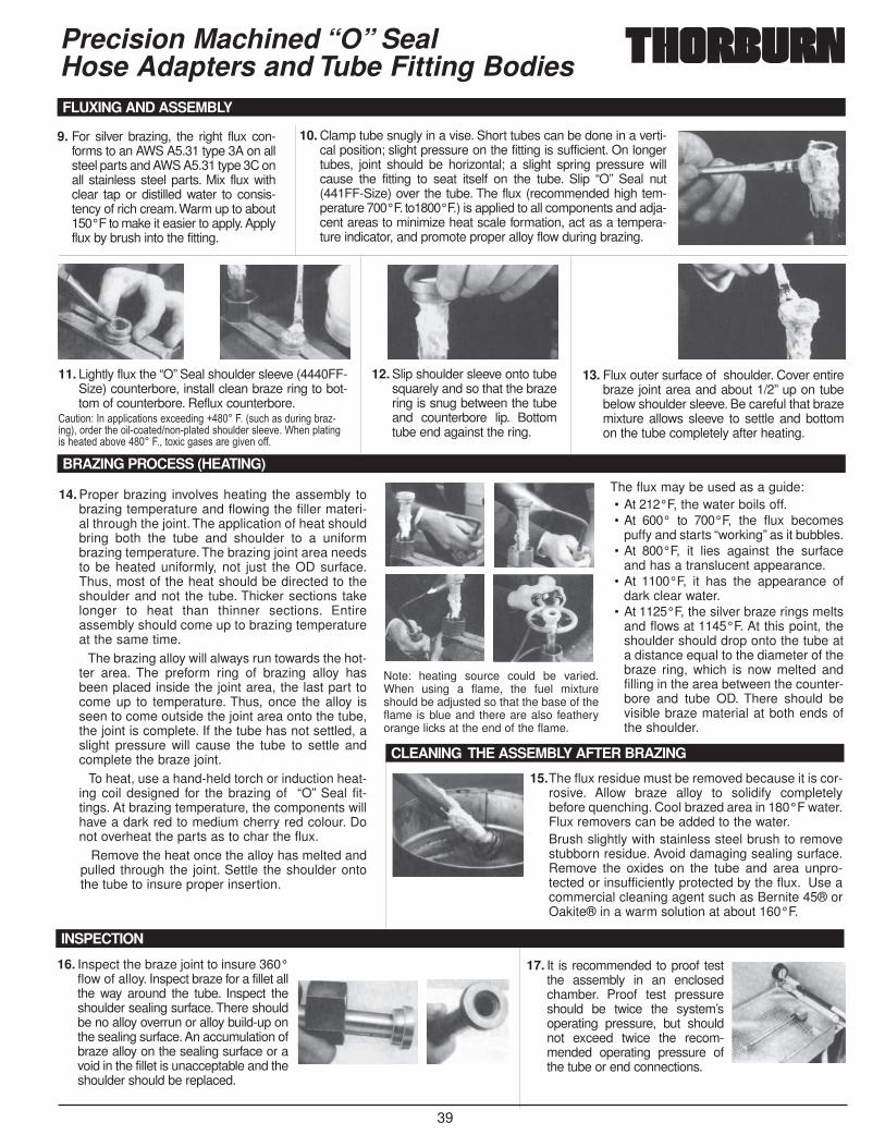
39
Precision Machined “O” Seal Hose Adapters and Tube Fitting Bodies
9. For silver brazing, the right flux con-forms to an AWS A5.31 type 3A on allsteel parts and AWS A5.31 type 3C onall stainless steel parts. Mix flux withclear tap or distilled water to consis-tency of rich cream.Warm up to about150°F to make it easier to apply. Applyflux by brush into the fitting.
14. Proper brazing involves heating the assembly tobrazing temperature and flowing the filler materi-al through the joint. The application of heat shouldbring both the tube and shoulder to a uniformbrazing temperature. The brazing joint area needsto be heated uniformly, not just the OD surface.Thus, most of the heat should be directed to theshoulder and not the tube. Thicker sections takelonger to heat than thinner sections. Entireassembly should come up to brazing temperatureat the same time.
The brazing alloy will always run towards the hot-ter area. The preform ring of brazing alloy hasbeen placed inside the joint area, the last part tocome up to temperature. Thus, once the alloy isseen to come outside the joint area onto the tube,the joint is complete. If the tube has not settled, aslight pressure will cause the tube to settle andcomplete the braze joint.
To heat, use a hand-held torch or induction heat-ing coil designed for the brazing of “O” Seal fit-tings. At brazing temperature, the components willhave a dark red to medium cherry red colour. Donot overheat the parts as to char the flux.
Remove the heat once the alloy has melted andpulled through the joint. Settle the shoulder ontothe tube to insure proper insertion.
10. Clamp tube snugly in a vise. Short tubes can be done in a verti-cal position; slight pressure on the fitting is sufficient. On longertubes, joint should be horizontal; a slight spring pressure willcause the fitting to seat itself on the tube. Slip “O” Seal nut(441FF-Size) over the tube. The flux (recommended high tem-perature 700°F. to1800°F.) is applied to all components and adja-cent areas to minimize heat scale formation, act as a tempera-ture indicator, and promote proper alloy flow during brazing.
FLUXING AND ASSEMBLY
BRAZING PROCESS (HEATING)
CLEANING THE ASSEMBLY AFTER BRAZING
INSPECTION
11. Lightly flux the “O” Seal shoulder sleeve (4440FF-Size) counterbore, install clean braze ring to bot-tom of counterbore. Reflux counterbore.
12. Slip shoulder sleeve onto tubesquarely and so that the brazering is snug between the tubeand counterbore lip. Bottomtube end against the ring.
13. Flux outer surface of shoulder. Cover entirebraze joint area and about 1/2” up on tubebelow shoulder sleeve. Be careful that brazemixture allows sleeve to settle and bottomon the tube completely after heating.
/.)���9����((5�,)���'��$,������H�����4��1'.,��'�.�����2�6����3!������)�����5�,�)������(5)��'��.5���'5������?����(5)����'���)��2���������4�!�)�$�,��'�'�����������##�
15.The flux residue must be removed because it is cor-rosive. Allow braze alloy to solidify completelybefore quenching. Cool brazed area in 180°F water.Flux removers can be added to the water.Brush slightly with stainless steel brush to removestubborn residue. Avoid damaging sealing surface.Remove the oxides on the tube and area unpro-tected or insufficiently protected by the flux. Use acommercial cleaning agent such as Bernite 45® orOakite® in a warm solution at about 160°F.
16. Inspect the braze joint to insure 360°flow of alloy. Inspect braze for a fillet allthe way around the tube. Inspect theshoulder sealing surface. There shouldbe no alloy overrun or alloy build-up onthe sealing surface. An accumulation ofbraze alloy on the sealing surface or avoid in the fillet is unacceptable and theshoulder should be replaced.
17. It is recommended to proof testthe assembly in an enclosedchamber. Proof test pressureshould be twice the system’soperating pressure, but shouldnot exceed twice the recom-mended operating pressure ofthe tube or end connections.
The flux may be used as a guide:• At 212°F, the water boils off.• At 600° to 700°F, the flux becomes
puffy and starts “working” as it bubbles.• At 800°F, it lies against the surface
and has a translucent appearance.• At 1100°F, it has the appearance of
dark clear water.• At 1125°F, the silver braze rings melts
and flows at 1145°F. At this point, theshoulder should drop onto the tube ata distance equal to the diameter of thebraze ring, which is now melted andfilling in the area between the counter-bore and tube OD. There should bevisible braze material at both ends ofthe shoulder.
Note: heating source could be varied.When using a flame, the fuel mixtureshould be adjusted so that the base of theflame is blue and there are also featheryorange licks at the end of the flame.
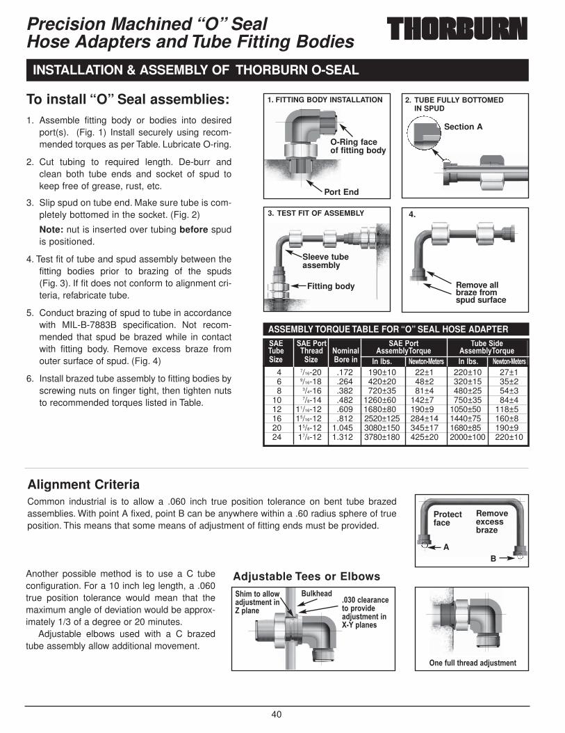
40
To install “O” Seal assemblies:1. Assemble fitting body or bodies into desired
port(s). (Fig. 1) Install securely using recom-mended torques as per Table. Lubricate O-ring.
2. Cut tubing to required length. De-burr andclean both tube ends and socket of spud tokeep free of grease, rust, etc.
3. Slip spud on tube end. Make sure tube is com-pletely bottomed in the socket. (Fig. 2)
Note: nut is inserted over tubing before spudis positioned.
4. Test fit of tube and spud assembly between thefitting bodies prior to brazing of the spuds (Fig. 3). If fit does not conform to alignment cri-teria, refabricate tube.
5. Conduct brazing of spud to tube in accordancewith MIL-B-7883B specification. Not recom-mended that spud be brazed while in contactwith fitting body. Remove excess braze fromouter surface of spud. (Fig. 4)
6. Install brazed tube assembly to fitting bodies byscrewing nuts on finger tight, then tighten nutsto recommended torques listed in Table.
Precision Machined “O” Seal Hose Adapters and Tube Fitting Bodies
INSTALLATION & ASSEMBLY OF THORBURN O-SEAL
O-Ring faceof fitting body
Section A
Fitting body
Protectface
AB
Removeexcessbraze
.,8�3*�/55*9/0K;438-+3�,+A�5/+-
$;5?.-/0�����<5-/)/+<-3*�)*2,0-/0K;438-+3�,+: ( 5/+-4
�+-�E;55�3.)-/0�/0K;438-+3
Adjustable Tees or Elbows
Sleeve tubeassembly
Remove allbraze fromspud surface
1. FITTING BODY INSTALLATION 2. TUBE FULLY BOTTOMED IN SPUD
3. TEST FIT OF ASSEMBLY 4.
Port End
�� ����*)3 ����*)3 �;1-�,0-�;1- �.)-/0 �*8,+/5 �44-815D�*)J;- �44-815D�*)J;-,=- ,=- $*)-�,+ �+�514� �-93*+ %-3-)4 �+�514� �-93*+ %-3-)4
4 7/16-20 .172 190±10 22±1 220±10 27±16 9/16-18 .264 420±20 48±2 320±15 35±28 3/4-16 .382 720±35 81±4 480±25 54±3
10 7/8-14 .482 1260±60 142±7 750±35 84±412 11/16-12 .609 1680±80 190±9 1050±50 118±516 15/16-12 .812 2520±125 284±14 1440±75 160±820 15/8-12 1.045 3080±150 345±17 1680±85 190±924 17/8-12 1.312 3780±180 425±20 2000±100 220±10
ASSEMBLY TORQUE TABLE FOR “O” SEAL HOSE ADAPTER
Another possible method is to use a C tubeconfiguration. For a 10 inch leg length, a .060true position tolerance would mean that themaximum angle of deviation would be approx-imately 1/3 of a degree or 20 minutes.
Adjustable elbows used with a C brazedtube assembly allow additional movement.
Alignment CriteriaCommon industrial is to allow a .060 inch true position tolerance on bent tube brazedassemblies. With point A fixed, point B can be anywhere within a .60 radius sphere of trueposition. This means that some means of adjustment of fitting ends must be provided.
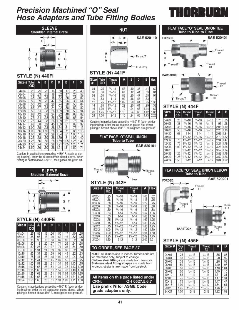
41
Precision Machined “O” Seal Hose Adapters and Tube Fitting Bodies
TO ORDER, SEE PAGE 37NOTE: All dimensions in inches. Dimensions arefor reference only, subject to change.Carbon steel fittings are made from barstock.Stainless steel fitting shapes are made fromforgings, straights are made from barstock.
Use prefix � for ASME Codegrade adapters only.
All items on this page listed underCRN: OH 0527.5.6.7
B
SAE 520101
STYLE (N) 442F
FLAT FACE “O” SEAL UNIONTube to Tube
��>�� ��� ������� ������� ���� �����>�� ��� �������� ������� ���� �����>�� ��� �������� �������� ���� �����>�� ��� �������� �������� ���� �����>�� ��� �������� �������� ���� �����>�� ��� ���� �������� ���� ������>�� ��� ���� ���� ���� ������>�� ��� �������� �������� ���� ������>�� ��� �������� ���� ���� ������>�� ��� �������� �������� ���� ������>�� ���� �������� �������� ���� ������>�� ���� �������� �������� ���� ������>�� ���� ��������� ��������� ���� ������>�� ���� ���� ���� ���� ����
Size # �;1- �.)-/0� �.)-/0� A Hex���� �� ��
SAE 520110
SLEEVEShoulder Internal Braze NUT
STYLE (N) 441F
�� ��� ������� ��� ��� ��� ��� ����� ��� �������� ��� ��� ��� ��� ����� ��� �������� ��� ��� ��� ��� ����� ��� ���� ��� ��� ��� ��� ������ ��� �������� ���� ��� ��� ��� ������ ��� �������� ���� ��� ��� ��� ������ ���� �������� ���� ��� ��� ���� ������ ���� ��������� ���� ��� ��� ���� ������ ���� ���� ���� ��� ��� ���� ����
Size �;1- �.)-/0 A $ � � '-F# OD T1
AB D
H (Hex)
STYLE (N) 440FI
��$�� ��� ��� ��� ��� ��� ��� ��� �����$�� ��� ��� ��� ��� ��� ��� ��� �����$�� ��� ��� ��� ��� ��� ��� ��� �����$�� ��� ��� ��� ��� ��� ��� ��� �����$�� ��� ��� ��� ��� ��� ��� ��� �����$�� ��� ��� ��� ��� ��� ��� ��� �����$�� ��� ��� ��� ��� ���� ��� ��� �����$�� ��� ��� ��� ��� ��� ��� ��� �����$�� ��� ��� ��� ��� ���� ��� ��� �����$�� ��� ��� ��� ��� ���� ��� ��� �����$�� ��� ��� ��� ��� ���� ��� ��� �����$�� ���� ��� ��� ��� ���� ��� ��� ������$�� ���� ��� ���� ��� ���� ��� ��� ������$�� ���� ��� ��� ��� ���� ��� ���� ������$�� ���� ��� ��� ��� ���� ��� ���� ������$�� ���� ��� ��� ��� ���� ���� ���� ������$�� ���� ��� ��� ��� ���� ���� ���� ������$�� ���� ��� ��� ��� ���� ���� ���� ����
Size # �;1- A $ � � � � �OD
/.)���9����((5�,)���'��$,������H�����4��1'.,��'�.������2�6���3!������)�����5�,�)������(5)��'5������?���(5)�����'���)��2���������4�!�)�$�,��'�'�����������##�
/.)���9����((5�,)���'��$,������H�����4��1'.,��'�.������2�6���3!������)�����5�,�)������(5)��'5������?���(5)�����'���)��2���������4�!�)�$�,��'�'�����������##�
/.)���9����((5�,)���'��$,������H�����4��1'.,��'�.������2�6���3!������)�����5�,�)������(5)���.)��?���(5)�����'���)��2���������4�!�)�$�,��'�'�����������##�
SLEEVEShoulder External Braze
STYLE (N) 440FE
��$�� ��� ��� ��� ��� ��� ��� ��� �����$�� ��� ��� ��� ��� ��� ��� ��� �����$�� ��� ��� ��� ��� ��� ��� ��� �����$�� ��� ���� ��� ��� ��� ��� ��� �����$�� ��� ���� ��� ��� ��� ��� ��� �����$�� ��� ���� ��� ��� ��� ��� ��� �����$�� ��� ���� ��� ��� ��� ��� ��� �����$�� ��� ���� ��� ��� ���� ��� ��� �����$�� ��� ���� ��� ��� ���� ��� ��� �����$�� ���� ���� ��� ��� ���� ��� ���� �����$�� ���� ���� ��� ��� ���� ��� ���� ������$�� ���� ���� ��� ��� ���� ��� ���� ������$�� ���� ���� ��� ��� ���� ���� ���� ������$�� ���� ���� ��� ��� ���� ��� ���� ������$�� ���� ���� ��� ��� ���� ���� ���� ����
Size # �;1- A $ � � � � �OD
A
ThreadT2
ThreadT1
Hex
ThreadT1E
BC
D E F G
A
/
D E G F
A SAE 520201
STYLE (N) 455F
FLAT FACE “O” SEAL UNION ELBOWTube to Tube
��>�� ��� ������� ������� ��� �����>�� ��� �������� ������� ��� �����>�� ��� �������� �������� ��� �����>�� ��� �������� ������� ���� �����>�� ��� �������� �������� ���� ������>�� ��� �������� �������� ���� ������>�� ��� ���� ���� ���� ������>�� ��� �������� �������� ���� ������>�� ��� �������� �������� ���� ������>�� ���� �������� �������� ���� ������>�� ���� ��������� ��������� ���� ������>�� ���� ���� ���� ���� ����
Size # �;1- �.)-/0� �.)-/0� A B���� �� ��
A
ThreadT2
ThreadT1
B
A
ThreadT2
ThreadT1
B
SAE 520401
STYLE (N) 444F
FLAT FACE “O” SEAL UNION TEETube to Tube to Tube
��>�� ��� ������� ������� ������� ���� �����>�� ��� �������� �������� �������� ���� �����>�� ��� �������� �������� �������� ���� ������>�� ��� �������� �������� �������� ���� ������>�� ��� ���� ���� ���� ���� ������>�� �������� �������� �������� ���� ������>�� ��� �������� �������� �������� ���� ������>�� ��� �������� �������� �������� ���� ������>�� ���� �������� �������� �������� ���� ������>�� ��������� �������� �������� ���� ������>�� ���� ��������� ��������� �������� ���� ������>�� ���� ��������� ��������� ��������� ���� ������>�� ���� ���� ���� ���� ���� ����
Size �;1- �.)-/0� �.)-/0� �.)-/0� A B# ���� �� �� ��
A
ThreadT2
ThreadT1 ThreadT3
B
A
ThreadT2
ThreadT1Thread
T3
B
������
$�����&
������
$�����&

42
Precision Machined “O” Seal Hose Adapters and Tube Fitting Bodies
TO ORDER, SEE PAGE 37NOTE: All dimensions in inches. Dimensions arefor reference only, subject to change.Carbon steel fittings are made from barstock.Stainless steel fitting shapes are made fromforgings, straights are made from barstock.
Use prefix � for ASME Codegrade adapters only.
All items on this page listed underCRN: OH 0527.5.6.7
/.)���9����((5�,)���'��$,������H�����4��1'.,��'.�����2�6���3!������)�����5�,�)������(5)���.)�?����(5)�����'���)��2���������4�!�)�$�,��'�'����������##�
SAE 520202
SAE 520429
STYLE (N) 449F
FLAT FACE “O” SEAL TO MALE NPTF 90° ELBOW
��>�� ��� ������� ������ ��� �����>�� ��� ������� ������ ��� ������>�� ��� �������� ������ ��� �����>�� ��� �������� ������ ��� ������>�� ��� �������� ������ ���� ������>�� ��� �������� ������ ���� ������>�� ��� �������� ������ ���� ������>�� ��� �������� ������ ���� ������>�� ��� �������� ������ ���� ������>�� ��� �������� ������ ���� ������>�� ��� ���� ������ ���� ������>�� ��� ���� ������ ���� ������>�� ��� �������� ������ ���� ������>�� ��� �������� ������ ���� ������>�� ��� �������� ������� ���� ������>�� � �������� ������ ���� ������>�� � �������� ������� ���� ������>�� ���� ��������� ������� ���� ������>�� ���� ��������� ���������� ���� ������>�� ���� ���� ���������� ���� ����
Size # �;1- ���� %/5-� A B���� -/5 ����
B
A
B
A
SAE 520102
STYLE (N) 448F
FLAT FACE “O” SEAL TO MALE NPTF
��>�� ��� ������� ������ ������>�� ��� ������� ������ ������>�� ��� ������� ������ ������>�� ��� ������� ������ ������>�� ��� �������� ������ ������>�� ��� �������� ������ ������>�� ��� �������� ������ ������>�� ��� �������� ������ ������>�� ��� �������� ������ ������>�� ��� �������� ������ ������>�� ��� �������� ������ ������>�� ��� �������� ������ ������>�� ��� ���� ������ ������>�� ��� ���� ������ ������>�� ��� ���� ������� ������>�� ��� �������� ������ ������>�� ��� �������� ������ ������>�� ��� �������� ������� ������>�� � �������� ������ ������>�� � �������� ������� ������>�� � �������� ���������� ������>�� ���� ��������� ������� ������>�� ���� ��������� ���������� ������>�� ���� ���� ���������� ����
Size # �;1- ���� %/5-� A���� -/5 ����
A
Size # �;1-� “S” Boss A���� Seal
SAE 520120
STYLE (N) 448FO
FLAT FACE “O” SEAL TO MALE “O”RING BOSS STRAIGHT
��>�� ��� ������� ������ ������>�� ��� ������� ������� ������>�� ��� ������� ������ ������>�� ��� ������� ������� ������>�� ��� ������� ������ ������>�� ��� �������� ������ ������>�� ��� �������� ������� ������>�� ��� �������� ������ ������>�� ��� �������� ������� ������>�� ��� �������� ������ ������>�� ��� �������� ������ ������>�� ��� �������� �������� ������>�� ��� �������� �������� ������>�� ��� �������� ������� ������>�� ��� �������� ������ ������>�� ��� �������� ������ ������>�� ��� �������� �������� ������>�� ��� �������� �������� ������>�� ��� �������� �������� ������>�� ��� ���� ������ ������>�� ��� ���� ������ ������>�� ��� ���� �������� ������>�� ��� ���� �������� ������>�� ��� �������� ������� ������>�� ��� �������� ������ ������>�� ��� �������� ������ ������>�� ��� �������� �������� ������>�� ��� �������� �������� ������>�� ��� �������� �������� ������>�� � �������� ������ ������>�� � �������� ������ ������>�� � �������� �������� ������>�� � �������� �������� ������>�� � �������� �������� ������>�� � �������� ������� ������>�� ���� ��������� �������� ������>�� ���� ��������� ������� ������>�� ���� ��������� ������� ������>�� ���� ���� ������� ������>�� ���� ���� ������� ����
A
STYLE (N) 445FFO
FLAT FACE “O” SEAL TEERun:Tube to Tube Side: O-Ring Boss
��>�� ��� ������� ������� ������ ��� ���� ��� �����>�� ��� ������� ������� ������� ��� ���� ��� �����>�� ��� �������� �������� ������� ��� ���� ��� �����>�� ��� �������� �������� ������ ���� ���� ��� �����>�� ��� �������� �������� ������ ���� ���� ��� �����>�� ��� ���� ���� ������ ���� ���� ��� �����>�� ��� �������� �������� ������ ���� ���� ��� �����>�� ��� �������� �������� �������� ���� ���� ��� �����>�� ��� �������� �������� �������� ���� ���� ��� �����>�� ���� �������� �������� �������� ���� ���� ��� �����>�� ���� ��������� ��������� ������� ���� ���� ��� ������>�� ���� ���� ���� ������� ���� ���� ��� ����
Size# �;1- �.)-/0� �.)-/0� �.)-/0� A B C E���� �� �� ��
AA
ORSThread T2
ORSThread T1
SAE O-ringThread T3
B
C
E
AA
ORSThread T2
ORSThread T1
SAE O-ringThread T3
B
C
C
������
$�����&
������
$�����&
STYLE (N) 442BHF
FLAT FACE “O”SEAL BULKHEAD UNION
��>�� ��� ������� ������� ���� ���� ��� �����>�� ��� �������� �������� ���� ���� ��� ������>�� ��� �������� �������� ���� ���� ��� ������>�� ��� �������� �������� ���� ���� ��� ������>�� ��� ���� �������� ���� ���� ��� ������>�� ��� ���� ���� ���� ���� ��� ������>�� ��� �������� �������� ���� ���� ��� ������>�� ���� �������� �������� ���� ���� ��� ������>�� ���� ��������� �������� ���� ���� ��� ������>�� ���� ��������� ��������� ���� ���� ���� ������>�� ���� ���� ���� ���� ���� ���� ����
Size# �;1- �.)-/0� �.)-/0� A B E '-F���� �� �� ��
A
ORSThread T2
ORSThread T1
Hex
B
E
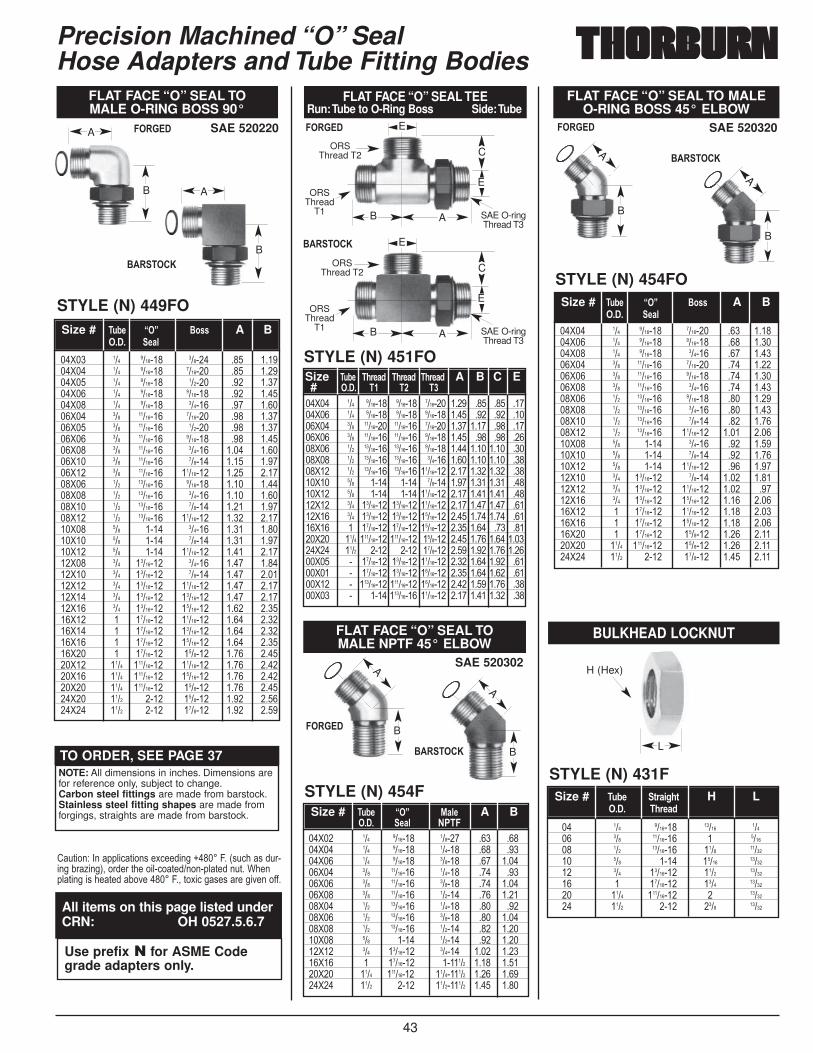
43
Precision Machined “O” Seal Hose Adapters and Tube Fitting Bodies
TO ORDER, SEE PAGE 37NOTE: All dimensions in inches. Dimensions arefor reference only, subject to change.Carbon steel fittings are made from barstock.Stainless steel fitting shapes are made fromforgings, straights are made from barstock.
Use prefix � for ASME Codegrade adapters only.
All items on this page listed underCRN: OH 0527.5.6.7
/.)���9����((5�,)���'��$,������H�����4��1'.,��'�.������2�6���3!������)�����5�,�)������(5)���.)��?���(5)�����'���)��2���������4�!�)�$�,��'�'�����������##�
STYLE (N) 451FO
FLAT FACE “O” SEAL TEERun:Tube to O-Ring Boss Side:Tube
��>�� ��� ������� ������� ������� ���� ��� ��� �����>�� ��� ������� ������� ������� ���� ��� ��� �����>�� ��� �������� �������� ������� ���� ���� ��� �����>�� ��� �������� �������� ������� ���� ��� ��� �����>�� ��� �������� �������� ������� ���� ���� ���� �����>�� ��� �������� �������� ������ ���� ���� ���� �����>�� ��� �������� �������� �������� ���� ���� ���� �����>�� ��� ���� ���� ������ ���� ���� ���� �����>�� ��� ���� ���� �������� ���� ���� ���� �����>�� ��� �������� �������� �������� ���� ���� ���� �����>�� ��� �������� �������� �������� ���� ���� ���� �����>�� � �������� �������� �������� ���� ���� ��� �����>�� ���� ��������� ��������� ������� ���� ���� ���� ������>�� ���� ���� ���� ������� ���� ���� ���� ������>�� � �������� �������� �������� ���� ���� ���� �����>�� � �������� �������� �������� ���� ���� ���� �����>�� � ��������� ��������� �������� ���� ���� ���� �����>�� � ���� ��������� �������� ���� ���� ���� ���
Size �;1-� �.)-/0 �.)-/0 �.)-/0 A B C E# ���� �� �� ��
B
E
A
ORSThread T2
ORSThread
T1 SAE O-ringThread T3
C
E
SAE 520220
STYLE (N) 449FO
FLAT FACE “O” SEAL TO MALE O-RING BOSS 90°
��>�� ��� ������� ������ ��� ������>�� ��� ������� ������� ��� ������>�� ��� ������� ������ ��� ������>�� ��� ������� ������� ��� ������>�� ��� ������� ������ ��� ������>�� ��� �������� ������� ��� ������>�� ��� �������� ������ ��� ������>�� ��� �������� ������� ��� ������>�� ��� �������� ������ ���� ������>�� ��� �������� ������ ���� ������>�� ��� �������� �������� ���� ������>�� ��� �������� ������� ���� ������>�� ��� �������� ������ ���� ������>�� ��� �������� ������ ���� ������>�� ��� �������� �������� ���� ������>�� ��� ���� ������ ���� ������>�� ��� ���� ������ ���� ������>�� ��� ���� �������� ���� ������>�� ��� �������� ������ ���� ������>�� ��� �������� ������ ���� ������>�� ��� �������� �������� ���� ������>�� ��� �������� �������� ���� ������>�� ��� �������� �������� ���� ������>�� � �������� �������� ���� ������>�� � �������� �������� ���� ������>�� � �������� �������� ���� ������>�� � �������� ������� ���� ������>�� ���� ��������� �������� ���� ������>�� ���� ��������� �������� ���� ������>�� ���� ��������� ������� ���� ������>�� ���� ���� ������� ���� ������>�� ���� ���� ������� ���� ����
Size # �;1-� ���� $*44 A B���� -/5
B
A
B
A
SAE 520320
STYLE (N) 454FO
FLAT FACE “O” SEAL TO MALEO-RING BOSS 45° ELBOW
��>�� ��� ������� ������� ��� ������>�� ��� ������� ������� ��� ������>�� ��� ������� ������ ��� ������>�� ��� �������� ������� ��� ������>�� ��� �������� ������� ��� ������>�� ��� �������� ������ ��� ������>�� ��� �������� ������� ��� ������>�� ��� �������� ������ ��� ������>�� ��� �������� ������ ��� ������>�� ��� �������� �������� ���� ������>�� ��� ���� ������ ��� ������>�� ��� ���� ������ ��� ������>�� ��� ���� �������� ��� ������>�� ��� �������� ������ ���� ������>�� ��� �������� �������� ���� �����>�� ��� �������� �������� ���� ������>�� � �������� �������� ���� ������>�� � �������� �������� ���� ������>�� � �������� ������� ���� ������>�� ���� ��������� ������� ���� ������>�� ���� ���� ������� ���� ����
Size # �;1-� ���� $*44 A B���� -/5
A
B
A
B
SAE 520302
STYLE (N) 454F
FLAT FACE “O” SEAL TO MALE NPTF 45° ELBOW
��>�� ��� ������� ������ ��� �����>�� ��� ������� ������ ��� �����>�� ��� ������� ������ ��� ������>�� ��� �������� ������ ��� �����>�� ��� �������� ������ ��� ������>�� ��� �������� ������ ��� ������>�� ��� �������� ������ ��� �����>�� ��� �������� ������ ��� ������>�� ��� �������� ������ ��� ������>�� ��� ���� ������ ��� ������>�� ��� �������� ������ ���� ������>�� � �������� ������� ���� ������>�� ���� ��������� ���������� ���� ������>�� ���� ���� ���������� ���� ����
Size # �;1- ���� %/5- A B���� -/5 ����
A
B
A
B
������
$�����&
������������
$�����&
$�����&
������
$�����&
B
E
A
ORSThread T2
ORSThread
T1 SAE O-ringThread T3
C
E
STYLE (N) 431F
BULKHEAD LOCKNUT
�� ��� ������� ����� ����� ��� �������� � ������ ��� �������� ���� ������� ��� ���� ����� ������� ��� �������� ���� ������� � �������� ���� ������� ���� ��������� � ������� ���� ���� ���� �����
Size # �;1- 3)/,>.3 H L���� �.)-/0
L
H (Hex)
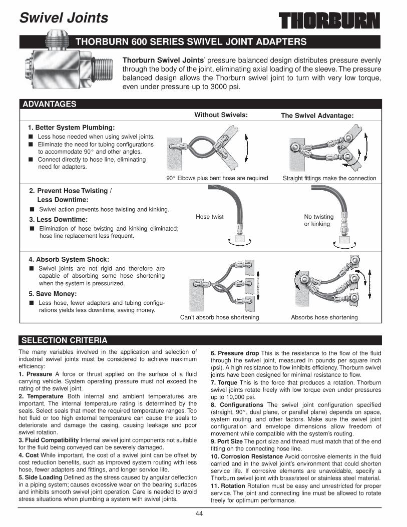
44
Swivel Joints
THORBURN 600 SERIES SWIVEL JOINT ADAPTERS
1. Better System Plumbing:■ Less hose needed when using swivel joints.■ Eliminate the need for tubing configurations
to accommodate 90° and other angles.■ Connect directly to hose line, eliminating
need for adapters.
2. Prevent Hose Twisting / Less Downtime:
■ Swivel action prevents hose twisting and kinking.
3. Less Downtime:■ Elimination of hose twisting and kinking eliminated;
hose line replacement less frequent.
4. Absorb System Shock:■ Swivel joints are not rigid and therefore are
capable of absorbing some hose shorteningwhen the system is pressurized.
5. Save Money:■ Less hose, fewer adapters and tubing configu-
rations yields less downtime, saving money.
Without Swivels: The Swivel Advantage:
90° Elbows plus bent hose are required
Can’t absorb hose shortening Absorbs hose shortening
Hose twist No twistingor kinking
Straight fittings make the connection
ADVANTAGES
SELECTION CRITERIAThe many variables involved in the application and selection ofindustrial swivel joints must be considered to achieve maximumefficiency:1. Pressure A force or thrust applied on the surface of a fluidcarrying vehicle. System operating pressure must not exceed therating of the swivel joint.2. Temperature Both internal and ambient temperatures areimportant. The internal temperature rating is determined by theseals. Select seals that meet the required temperature ranges. Toohot fluid or too high external temperature can cause the seals todeteriorate and damage the casing, causing leakage and poorswivel rotation.3. Fluid Compatibility Internal swivel joint components not suitablefor the fluid being conveyed can be severely damaged.4. Cost While important, the cost of a swivel joint can be offset bycost reduction benefits, such as improved system routing with lesshose, fewer adapters and fittings, and longer service life.5. Side Loading Defined as the stress caused by angular deflectionin a piping system; causes excessive wear on the bearing surfacesand inhibits smooth swivel joint operation. Care is needed to avoidstress situations when plumbing a system with swivel joints.
6. Pressure drop This is the resistance to the flow of the fluidthrough the swivel joint, measured in pounds per square inch(psi). A high resistance to flow inhibits efficiency. Thorburn swiveljoints have been designed for minimal resistance to flow.7. Torque This is the force that produces a rotation. Thorburnswivel joints rotate freely with low torque even under pressuresup to 10,000 psi.8. Configurations The swivel joint configuration specified(straight, 90°, dual plane, or parallel plane) depends on space,system routing, and other factors. Make sure the swivel jointconfiguration and envelope dimensions allow freedom ofmovement while compatible with the system’s routing.9. Port Size The port size and thread must match that of the endfitting on the connecting hose line.10. Corrosion Resistance Avoid corrosive elements in the fluidcarried and in the swivel joint’s environment that could shortenservice life. If corrosive elements are unavoidable, specify aThorburn swivel joint with brass/steel or stainless steel material.11. Rotation Rotation must be easy and unrestricted for properservice. The joint and connecting line must be allowed to rotatefreely for optimum performance.
Thorburn Swivel Joints’ pressure balanced design distributes pressure evenlythrough the body of the joint, eliminating axial loading of the sleeve.The pressurebalanced design allows the Thorburn swivel joint to turn with very low torque,even under pressure up to 3000 psi.
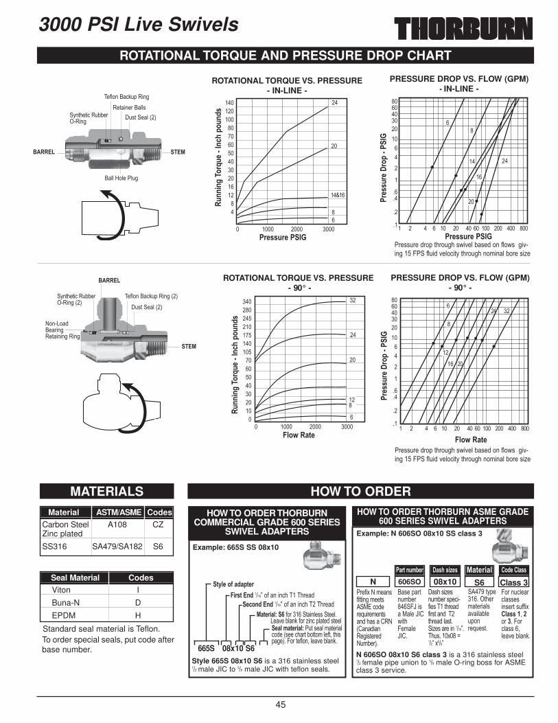
45
ROTATIONAL TORQUE AND PRESSURE DROP CHART
MATERIALS HOW TO ORDER
���������������
�
����
��
��
3000 PSI Live Swivels
��%$�����
.')� �5�1�3
�55�=�5��"5.�
0�)������55' D�)��)�,�0.22����0���
��#5����,:.( 0���
� ���� ���� ����
� ���� ���� ����
��K��
��
��
��
��
��
�
��
��
��
��
����
� � � � �� �� �� �� ��� ��� ��� ���
� � � � �� �� �� �� ��� ��� ��� ���
���
�
�
��
��
����
��
ROTATIONAL TORQUE VS. PRESSURE- IN-LINE -
�;++
,+>��*
)J;-
� ��+<.
�*;
+04
�;++
,+>��*
)J;-
� ��+<.
�*;
+04
�5*9��/3- �5*9��/3-
�)-44;)-���� �)-44;)-����
�)-44;
)-��)*� ��
��
�)-44;
)-��)*� ��
��
PRESSURE DROP VS. FLOW (GPM)- 90° -
ROTATIONAL TORQUE VS. PRESSURE- 90° -
PRESSURE DROP VS. FLOW (GPM) �IN-LINE -
�����������������������������
������������������������������������
���������������
�
����
��
��
"��''.�����(�)���.���'A���5�2'�����#5�A'�������������4" �#5.����5�,�)D�)���.�����&��5�2����'�6�
"��''.�����(�)���.���'A���5�2'�����#5�A'�������������4" �#5.����5�,�)D�)���.�����&��5�2����'�6�
��%
$�����
.')� �5�1�3
%���<�������0�)������0���
D�)��)�,�0.22����0����1�3
��#5����,:.( 0����1�3
Material ASTM/ASME CodesCarbon Steel A108 CZZinc plated
SS316 SA479/SA182 S6
Seal Material CodesViton I
Buna-N D
EPDM H
Standard seal material is Teflon.To order special seals, put code afterbase number.
"��#�$�%�&��'#�))����&��)'� *+�,�����-.���&��)'���'��/0%1/���0���')���%.&2��3�
�'��(�)�.&2����� 4L��'�*5��L�/A�)�4�&5�L�/�
'��'�6�'�.&2���'(�,��#��'����)���#��')������)����5')� �6�'�����������7���.'!���$���8���7�$���7
�����)D(�������)���&)���5'��525�.(����-.�')�
4����.,5��,5''�'��'��)�'.##�$�5/44��!��������4��,5''��!5����25�:�
Class 3S608x10606SON�/)3�+;81-) �/4.�4,=-4 %/3-),/5 �*0-��5/44
3D5-�*E�/0/3-)�,)43��+0 ����7��#�����,���������
-<*+0��+0 ����7��#�����,���������%/3-),/5B�� #������� )��5�''� )��5�
<����25�:�#���6��,�(5)��')��5-/5�8/3-),/5B ".)�'�5�&)���5,���1'���,��)�2�))�&�5�#)!�)��'(��3��4���)�#5��!�5����25�:�
HOW TO ORDER THORBURNCOMMERCIAL GRADE 600 SERIES
SWIVEL ADAPTERS
665S 08x10 S6
Style 665S 08x10 S6 is a 316 stainless steel���7�male JIC to ��� male JIC with teflon seals.
Example: 665S SS 08x10
HOW TO ORDER THORBURN ASME GRADE600 SERIES SWIVEL ADAPTERS
Example: N 606SO 08x10 SS class 3
N 606SO 08x10 S6 class 3 is a 316 stainless steel�����#�male pipe union to ��� male O-ring boss for ASMEclass 3 service.
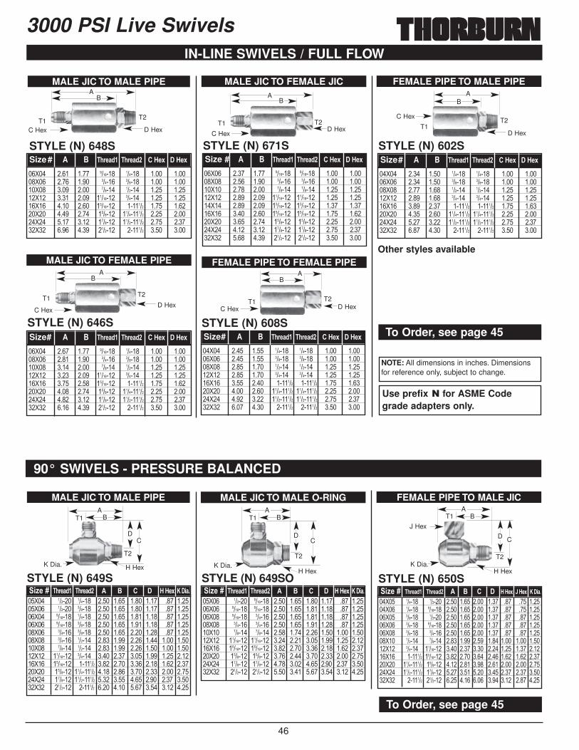
46
3000 PSI Live Swivels
MALE JIC TO MALE O-RING
STYLE (N) 649SO
��>�� ������ ������� ���� ���� ���� ���� ��� ������>�� ������� ������� ���� ���� ���� ���� ��� ������>�� ������� ������ ���� ���� ���� ���� ��� ������>�� ������ ������ ���� ���� ���� ���� ��� ������>�� ������ ������ ���� ���� ���� ���� ���� ������>�� �������� �������� ���� ���� ���� ���� ���� ������>�� �������� �������� ���� ���� ���� ���� ���� ������>�� ������� ������� ���� ���� ���� ���� ���� ������>�� ������� ������� ���� ���� ���� ���� ���� ������>�� ������� ������� ���� ���� ���� ���� ���� ����
,=-�H �.)-/0� �.)-/0� � $ �� � '�'-F &��,/�
T1
T2
BA
K Dia.H Hex
DC
FEMALE PIPE TO MALE JIC
STYLE (N) 650S
��>�� ������ ������ ���� ���� ���� ���� ��� ��� ������>�� ������ ������� ���� ���� ���� ���� ��� ��� ������>�� ������ ������ ���� ���� ���� ���� ��� ��� ������>�� ������ ������� ���� ���� ���� ���� ��� ��� ������>�� ������ ������ ���� ���� ���� ���� ��� ��� ������>�� ������ ������ ���� ���� ���� ���� ���� ���� ������>�� ������ �������� ���� ���� ���� ���� ���� ���� ������>�� ������� �������� ���� ���� ���� ���� ���� ���� ������>�� ���������� ������� ���� ���� ���� ���� ���� ���� ������>�� ���������� ������� ���� ���� ���� ���� ���� ���� ������>�� ������� ������� ���� ���� ���� ���� ���� ���� ����
,=-�H �.)-/0� �.)-/0� � $ �� � '�'-F ��'-F &��,/�
T1
T2
BA
K Dia.H Hex
D C
J Hex
MALE JIC TO MALE PIPE
STYLE (N) 649S
��>�� ������ ������ ���� ���� ���� ���� ��� ������>�� ������ ������ ���� ���� ���� ���� ��� ������>�� ������� ������ ���� ���� ���� ���� ��� ������>�� ������� ������ ���� ���� ���� ���� ��� ������>�� ������ ������ ���� ���� ���� ���� ��� ������>�� ������ ������ ���� ���� ���� ���� ���� ������>�� ������ ������ ���� ���� ���� ���� ���� ������>�� �������� ������ ���� ���� ���� ���� ���� ������>�� �������� ������� ���� ���� ���� ���� ���� ������>�� ������� ���������� ���� ���� ���� ���� ���� ������>�� ������� ���������� ���� ���� ���� ���� ���� ������>�� ������� ������� ���� ���� ���� ���� ���� ����
,=-�H �.)-/0� �.)-/0� � $ �� � '�'-F &��,/�
T1
T2
BA
K Dia. H Hex
DC
90° SWIVELS - PRESSURE BALANCED
NOTE: All dimensions in inches. Dimensionsfor reference only, subject to change.
Use prefix � for ASME Codegrade adapters only.
To Order, see page 45
To Order, see page 45
MALE JIC TO FEMALE PIPE
IN-LINE SWIVELS / FULL FLOW
STYLE (N) 646S
��>�� ���� ���� ������� ������ ���� ������>�� ���� ���� ������ ������ ���� ������>�� ���� ���� ������ ������ ���� ������>�� ���� ���� �������� ������ ���� ������>�� ���� ���� �������� ������� ���� ������>�� ���� ���� ������� ���������� ���� ������>�� ���� ���� ������� ���������� ���� ������>�� ���� ���� ������� ������� ���� ����
Size# � $ �.)-/0� �.)-/0� ��'-F ��'-F
T1T2
BA
MALE JIC TO MALE PIPE
STYLE (N) 648S
��>�� ���� ���� ������� ������ ���� ������>�� ���� ���� ������ ������ ���� ������>�� ���� ���� ������ ������ ���� ������>�� ���� ���� �������� ������ ���� ������>�� ���� ���� �������� ������� ���� ������>�� ���� ���� ������� ���������� ���� ������>�� ���� ���� ������� ���������� ���� ������>�� ���� ���� ������� ������� ���� ����
Size# � $ �.)-/0� �.)-/0� ��'-F ��'-F
MALE JIC TO FEMALE JIC
STYLE (N) 671S
��>�� ���� ���� ������� ������� ���� ������>�� ���� ���� ������ ������ ���� ������>�� ���� ���� ������ ������ ���� ������>�� ���� ���� �������� �������� ���� ������>�� ���� ���� �������� �������� ���� ������>�� ���� ���� �������� �������� ���� ������>�� ���� ���� ������� ������� ���� ������>�� ���� ���� ������� ������� ���� ������>�� ���� ���� ������� ������� ���� ����
Size # � $ �.)-/0� �.)-/0� ��'-F ��'-F
FEMALE PIPE TO MALE PIPE
STYLE (N) 602S
��>�� ���� ���� ������ ������ ���� ������>�� ���� ���� ������ ������ ���� ������>�� ���� ���� ������ ������ ���� ������>�� ���� ���� ������ ������ ���� ������>�� ���� ���� ������� ������� ���� ������>�� ���� ���� ���������� ���������� ���� ������>�� ���� ���� ���������� ���������� ���� ������>�� ���� ���� ������� ������� ���� ����
Size# � $ �.)-/0� �.)-/0� ��'-F ��'-F
FEMALE PIPE TO FEMALE PIPE
STYLE (N) 608S
��>�� ���� ���� ������ ������ ���� ������>�� ���� ���� ������ ������ ���� ������>�� ���� ���� ������ ������ ���� ������>�� ���� ���� ������ ������ ���� ������>�� ���� ���� ������� ������� ���� ������>�� ���� ���� ���������� ���������� ���� ������>�� ���� ���� ���������� ���������� ���� ������>�� ���� ���� ������� ������� ���� ����
Size# � $ �.)-/0� �.)-/0� ��'-F ��'-F
T1 T2
BA
T1T2
BA
D HexC Hex D Hex
C Hex
D HexC Hex
D HexC HexD Hex
C Hex
T1 T2
BA
T1T2
BA
Other styles available
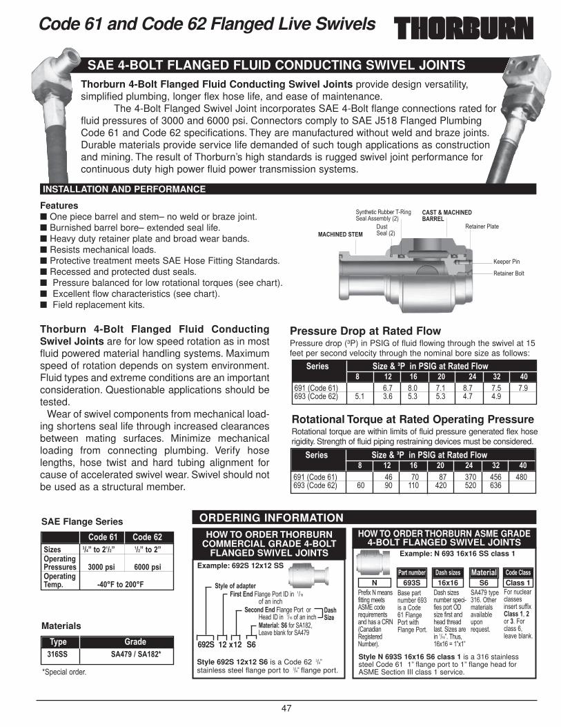
47
Code 61 and Code 62 Flanged Live Swivels
SAE 4-BOLT FLANGED FLUID CONDUCTING SWIVEL JOINTS
ORDERING INFORMATION
Thorburn 4-Bolt Flanged Fluid Conducting Swivel Joints provide design versatility,simplified plumbing, longer flex hose life, and ease of maintenance.
The 4-Bolt Flanged Swivel Joint incorporates SAE 4-Bolt flange connections rated forfluid pressures of 3000 and 6000 psi. Connectors comply to SAE J518 Flanged PlumbingCode 61 and Code 62 specifications. They are manufactured without weld and braze joints.Durable materials provide service life demanded of such tough applications as constructionand mining. The result of Thorburn’s high standards is rugged swivel joint performance forcontinuous duty high power fluid power transmission systems.
Thorburn 4-Bolt Flanged Fluid ConductingSwivel Joints are for low speed rotation as in mostfluid powered material handling systems. Maximumspeed of rotation depends on system environment.Fluid types and extreme conditions are an importantconsideration. Questionable applications should betested.
Wear of swivel components from mechanical load-ing shortens seal life through increased clearancesbetween mating surfaces. Minimize mechanicalloading from connecting plumbing. Verify hoselengths, hose twist and hard tubing alignment forcause of accelerated swivel wear. Swivel should notbe used as a structural member.
"��#�$�%�&��'#�))����&��)'� *+�,�����-.���&��)'���'��/0%1/���0���')���%.&2��3�
�'��(�)�.&2�������'��/�����45���"��)�A�)�45����"��)�
'��'�6�'�.&2���'(�,��#��'�(��)�� '�6��#��')�����)���5')�� �6�'����������7����.'!��$���8��7$�7
�����)D(�������)���&)���5'��525�.(����-.�')�
4����.,5��,5''�'��'��)�'.##�$�5/44��!��������4��,5''��!5����25�:�
Class 1S616x16693SN�/)3�+;81-) �/4.�4,=-4 %/3-),/5 �*0-��5/44
3D5-�*E�/0/3-)�,)43��+0 45����"��)�� ���������
�#�����,�-<*+0��+0 45����"��)�����
=��� ��������� �#�����,�%/3-),/5B�� #��� ����!<����25�:�#��� ����
HOW TO ORDER THORBURNCOMMERCIAL GRADE 4-BOLT
FLANGED SWIVEL JOINTS
692S 12 x12 S6
Style 692S 12x12 S6 is a Code 62 ���7stainless steel flange port to ���7�flange port.
Style N 693S 16x16 S6 class 1 is a 316 stainlesssteel Code 61 1” flange port to 1” flange head forASME Section III class 1 service.
Example: 692S 12x12 SS
HOW TO ORDER THORBURN ASME GRADE 4-BOLT FLANGED SWIVEL JOINTS
Example: N 693 16x16 SS class 1
����@�%��'����$�����
%��'�������% .') �5�1�3
M��(���"��
0�)�����"5)�
0�)�������5)
D�)��)�,�0.22�� ��0��� �5��''�&25D�1�3
INSTALLATION AND PERFORMANCE
Pressure Drop at Rated FlowPressure drop (³P) in PSIG of fluid flowing through the swivel at 15feet per second velocity through the nominal bore size as follows:
Rotational Torque at Rated Operating PressureRotational torque are within limits of fluid pressure generated flex hoserigidity. Strength of fluid piping restraining devices must be considered.
����1/�����3 ��� ��� ��� ��� ��� �������1/�����3 ��� ��� ��� ��� ��� ���
-),-4 ,=-�@�L� ,+�����/3��/3-0��5*9! �� �� �� �� �� ��
����1/�����3 �� �� �� ��� ��� �������1/�����3 �� �� ��� ��� ��� ���
-),-4 ,=-�@�L� ,+�����/3��/3-0��5*9! �� �� �� �� �� ��
Features■ One piece barrel and stem– no weld or braze joint.■ Burnished barrel bore– extended seal life.■ Heavy duty retainer plate and broad wear bands.■ Resists mechanical loads.■ Protective treatment meets SAE Hose Fitting Standards.■ Recessed and protected dust seals.■ Pressure balanced for low rotational torques (see chart).■ Excellent flow characteristics (see chart).■ Field replacement kits.
,=-4 �I���3*���I�� �I���3*����-)/3,+>�)-44;)-4 �����4, �����4,�-)/3,+>�-8� �����3*������
�*0-��� �*0-���SAE Flange Series
��� ���"�I���!�M�D- �)/0-
Materials
G (�,�5������
�/4.,=-

48
Code 61 and Code 62 Flanged Live Swivels
CODE 61 - 3000 PSIFLANGE PORT TO FLANGE PORT FLANGE PORT TO FLANGE HEAD
STYLE (N) 691S
��>�� ��� ���� ���� ���� ���� ���� ��� ������>�� � ���� ���� ���� ���� ���� � ������>�� ���� ���� ���� ���� ���� ���� ���� ������>�� ���� ���� ���� ���� ���� ���� ���� �������>�� � ���� ���� ���� ���� ���� � �������>�� ���� ���� ���� ���� ���� ���� ���� �����
,=-�H �� � $ �� � � � �3I514
D
C
E
Port “P”SAE 4-BoltFlange -Code 61
STYLE (N) 692S
��>�� ��� ���� ���� ���� ���� ���� ��� ��� ������>�� � ���� ���� ���� ���� ���� � � ������>�� ���� ���� ���� ���� ���� ���� ���� ���� ������>�� ���� ���� ���� ���� ���� ���� ���� ���� ������>�� � ���� ���� ���� ���� ���� � � �������>�� ���� ���� ���� ���� ���� ���� ���� ���� �����
,=-�H �� � $ �� � � � ' �3I514
Head “H”SAE 4-BoltFlange -Code 61
CODE 62 - 6000 PSIFLANGE PORT TO FLANGE PORT FLANGE PORT TO FLANGE HEAD
STYLE (N) 693S
��>�� ��� ���� ���� ���� ���� ���� ��� ������>�� ��� ���� ���� ���� ���� ���� ��� ������>�� � ���� ���� ���� ���� ���� � ������>�� ���� ���� ���� ���� ���� ���� ���� �������>�� ���� ���� ���� ���� ���� ���� ���� �������>�� � ���� ���� ���� ���� ���� � �����
,=-�H �� � $ �� � � � �3I514
STYLE (N) 694S
��>�� ��� ���� ���� ���� ���� ���� ��� ��� ������>�� ��� ���� ���� ���� ���� ���� ��� ��� ������>�� � ���� ���� ���� ���� ���� ���� ���� ������>�� ���� ���� ���� ���� ���� ���� ���� ���� �������>�� ���� ���� ���� ���� ���� ���� ���� ���� �������>�� � ���� ���� ���� ���� ���� � � �����
,=-�H �� � $ �� � � � ' �3I514
B
A
D
C
E
Port “P”SAE 4-BoltFlange -Code 61
B
A
D
C
E
Port “P”SAE 4-BoltFlange -Code 62
Head “H”SAE 4-BoltFlange -Code 62
B
A
D
C
E
Port “P”SAE 4-BoltFlange -Code 62
B
A
Replacement Seal Kits Kits contain dust and fluid seals, retaining plate and retaining screw.
Kit no. ��>�� ��>�� ��>�� ��>�� ��>�� ��>��$*0D�,=- �" �&�� �" �&�� �" �&�� �" �&�� �" �&�� �" �&��695TSK Series
Kit no. ��>�� ��>�� ��>�� ��>�� ��>�� ��>��$*0D�,=- �" �&�� �" �&�� �" �&�� �" �&�� �" �&�� �" �&��696TSK Series
NOTE: All dimensions in inches. Dimensions forreference only, subject to change.Use prefix � for ASME Code grade
adapters only.To order, see page 48
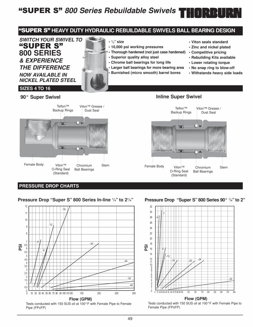
49
;�%����< 800 Series Rebuildable Swivels
;�%����< HEAVY DUTY HYDRAULIC REBUILDABLE SWIVELS BALL BEARING DESIGN
� �� �� �� �� �� �� �� �� �� ��� ������ ��� ��� ��� ���
��
��
���
���
���
���
���
���
��
��
��
�
�
�����
����
����
����
����
����
����
Pressure Drop “Super S” 800 Series In-line 1/4” to 21/4”
Flow (GPM)Tests conducted with 150 SUS oil at 100°F with Female Pipe to FemalePipe (FPxFP)
PS
I
� �� �� �� �� �� �� �� �� �� �� ����� ��� ��� ��� ��� ��� ��� ��� ���
��
��
��
������
��
��
��
��
��
��
��
��
��
������������������
Pressure Drop “Super S” 800 Series 90° 1/4” to 2”
Flow (GPM)Tests conducted with 150 SUS oil at 100°F with Female Pipe toFemale Pipe (FPxFP)
PS
I
��� ���
���
SIZES 4 TO 16
PRESSURE DROP CHARTS
SWITCH YOUR SWIVEL TO;�%����<800 SERIES& EXPERIENCE THE DIFFERENCENOW AVAILABLE IN NICKEL PLATED STEEL
• 1/2” size • 10,000 psi working pressures• Thorough hardened (not just case hardened)• Superior quality alloy steel• Chrome ball bearings for long life• Larger ball bearings for more bearing area• Burnished (micro smooth) barrel bores
• Viton seals standard• Zinc and nickel plated• Competitive pricing• Rebuilding Kits available• Lower rotating torque• No snap ring to blow-off• Withstands heavy side loads
Female Body Viton™ O-Ring Seal(Standard)
Teflon™Backup Rings
ChromiumBall Bearings
Viton™ Grease /Dust Seal
Stem
90° Super Swivel Inline Super Swivel
Female Body Viton™ O-Ring Seal(Standard)
Teflon™Backup Rings
ChromiumBall Bearings
Viton™ Grease /Dust Seal
Stem
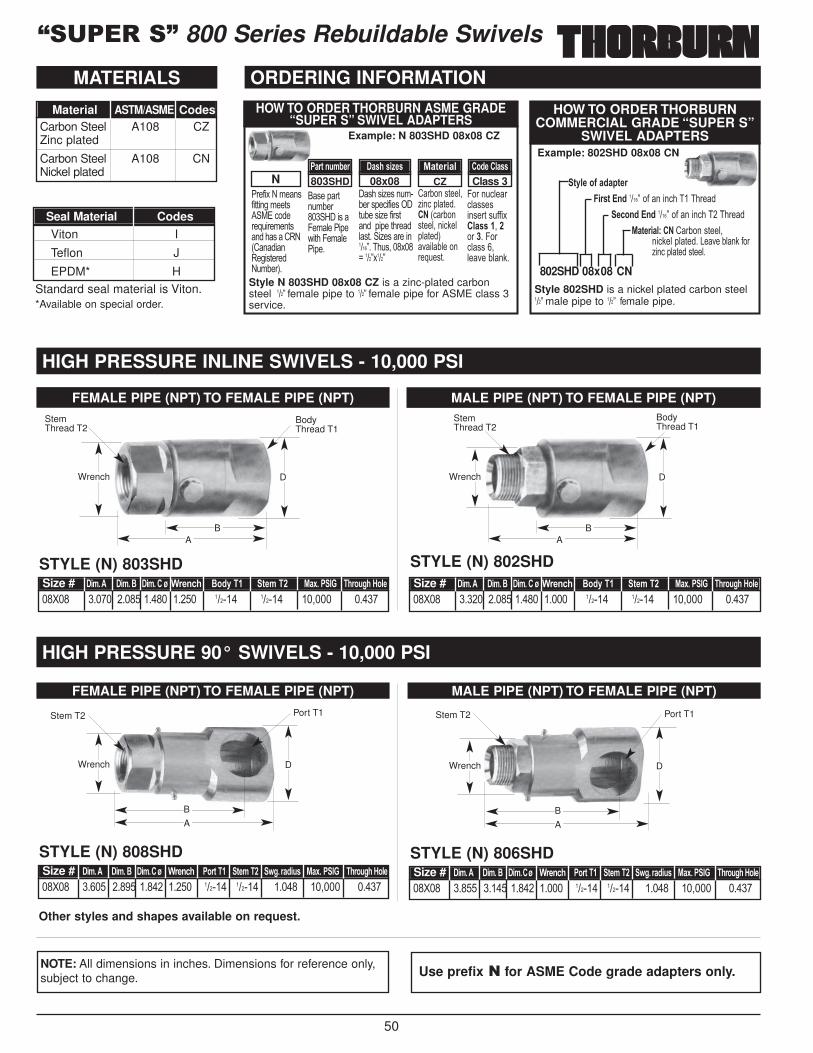
50
;�%����< 800 Series Rebuildable Swivels
"��#�$�%�&��'#�))����&��)'� *+�,�����-.���&��)'���'��/0%1/���0���')���%.&2��3�
�'��(�)�.&2����� = ��'�4�&5��"�(�A�)��4�&5�"�(��
'��'�6�'��.&�2���'(�,�#��'�� ).2��'�6��#��')���(�(��)���5')�� �6�'����������7����.'!���$��8����7$���7
/�2���')��5!6��,�(5)���� 1,�2��')��5!���,:�5(5)�3���525������-.�')�
4����.,5��,5''�'��'��)�'.##�$�5/44��!��������4��,5''��!5����25�:�
Class 3CZ08x08803SHDN�/)3�+;81-) �/4.�4,=-4 %/3-),/5 �*0-��5/44
3D5-�*E�/0/3-)�,)43��+0 ����7��#�����,���������
-<*+0��+0 ����7��#�����,���������%/3-),/5B����/�2���')��5!
��,:�5�(5)�� <����25�:�#���6��,�(5)��')��5�
HOW TO ORDER THORBURNCOMMERCIAL GRADE “SUPER S”
SWIVEL ADAPTERS
802SHD 08x08 CNStyle 802SHD is a nickel plated carbon steel���7�male pipe to ���7��#�male pipe.
Style N 803SHD 08x08 CZ is a zinc-plated carbonsteel ���7�female pipe to ���7�female pipe for ASME class 3service.
Example: 802SHD 08x08 CN
HOW TO ORDER THORBURN ASME GRADE“SUPER S” SWIVEL ADAPTERS
Example: N 803SHD 08x08 CZ
NOTE: All dimensions in inches. Dimensions for reference only,subject to change. Use prefix � for ASME Code grade adapters only.
FEMALE PIPE (NPT) TO FEMALE PIPE (NPT)
HIGH PRESSURE INLINE SWIVELS - 10,000 PSI
HIGH PRESSURE 90° SWIVELS - 10,000 PSI
ORDERING INFORMATION
STYLE (N) 803SHD
��>�� ����� ����� ����� ����� ������ ������ ��!��� �����Size # �,8��� �,8��$ �,8����N �)-+<. $*0D��� 3-8��� %/F����� �.)*;>.�'*5-
Wrench
StemThread T2
BodyThread T1
A
D
MATERIALS
Material ASTM/ASME CodesCarbon Steel A108 CZZinc plated
Carbon Steel A108 CNNickel plated
Seal Material CodesViton I
Teflon J
EPDM* H
Standard seal material is Viton.*Available on special order.
Other styles and shapes available on request.
B
FEMALE PIPE (NPT) TO FEMALE PIPE (NPT)
STYLE (N) 808SHD
��>�� ����� ����� ����� ����� ������ ������ ����� ��!��� �����Size # �,8��� �,8��$ �,8��N �)-+<. �*)3��� 3-8��� 9>� )/0,;4 %/F����� �.)*;>.�'*5-
Wrench
Stem T2 Port T1
A
D
B
MALE PIPE (NPT) TO FEMALE PIPE (NPT)
STYLE (N) 806SHD
��>�� ����� ����� ����� ����� ������ ������ ����� ��!��� �����Size # �,8��� �,8��$ �,8��N �)-+<. �*)3��� 3-8��� 9>� )/0,;4 %/F� ��� �.)*;>.�'*5-
Wrench
Stem T2 Port T1
A
D
B
MALE PIPE (NPT) TO FEMALE PIPE (NPT)
STYLE (N) 802SHD
��>�� ����� ����� ����� ����� ������ ������ ��!��� �����Size # �,8��� �,8��$ �,8����N �)-+<. $*0D��� 3-8��� %/F����� �.)*;>.�'*5-
Wrench
Stem Thread T2
BodyThread T1
A
D
B
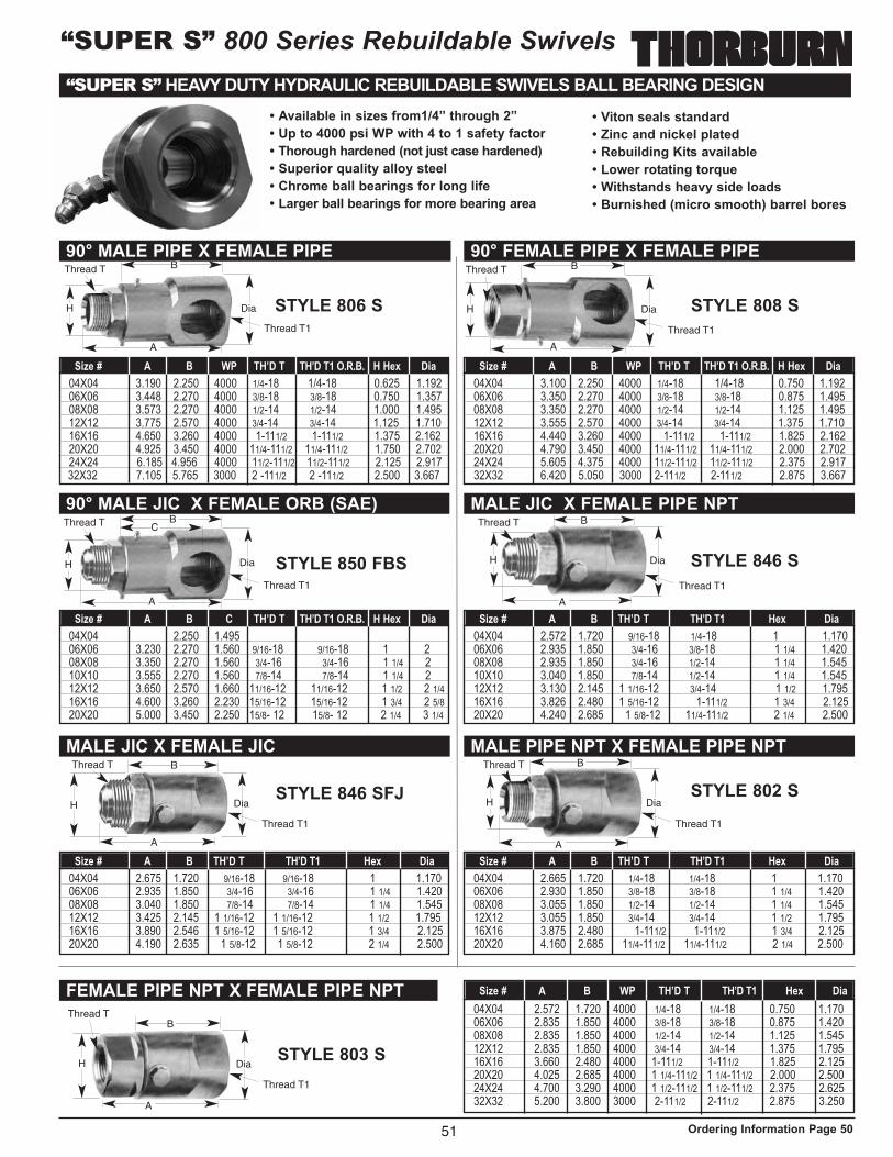
“SUPER S” 800 Series Rebuildable Swivels“SUPER S” HEAVY DUTY HYDRAULIC REBUILDABLE SWIVELS BALL BEARING DESIGN
• Available in sizes from1/4” through 2”
• Up to 4000 psi WP with 4 to 1 safety factor
• Thorough hardened (not just case hardened)
• Superior quality alloy steel
• Chrome ball bearings for long life
• Larger ball bearings for more bearing area
• Viton seals standard
• Zinc and nickel plated
• Rebuilding Kits available
• Lower rotating torque
• Withstands heavy side loads
• Burnished (micro smooth) barrel bores
90° MALE PIPE X FEMALE PIPE
04X04 3.190 2.250 4000 1/4-18 1/4-18 0.625 1.19206X06 3.448 2.270 4000 3/8-18 3/8-18 0.750 1.35708X08 3.573 2.270 4000 1/2-14 1/2-14 1.000 1.49512X12 3.775 2.570 4000 3/4-14 3/4-14 1.125 1.71016X16 4.650 3.260 4000 1-111/2 1-111/2 1.375 2.16220X20 4.925 3.450 4000 11/4-111/2 11/4-111/2 1.750 2.70224X24 6.185 4.956 4000 11/2-111/2 11/2-111/2 2.125 2.91732X32 7.105 5.765 3000 2 -111/2 2 -111/2 2.500 3.667
Size # A B WP TH’D T TH’D T1 O.R.B. H Hex Dia
90° MALE JIC X FEMALE ORB (SAE)
04X04 3.190 2.250 1.495 1/4-18 1/4-18 1.170 1.4606X06 3.230 2.270 1.560 9/16-18 9/16-18 1 208X08 3.350 2.270 1.560 3/4-16 3/4-16 1 1/4 2 10X10 3.555 2.270 1.560 7/8-14 7/8-14 1 1/4 2 12X12 3.650 2.570 1.660 11/16-12 11/16-12 1 1/2 2 1/416X16 4.600 3.260 2.230 15/16-12 15/16-12 1 3/4 2 5/820X20 5.000 3.450 2.250 15/8- 12 15/8- 12 2 1/4 3 1/4
Size # A B C TH’D T TH’D T1 O.R.B. H Hex Dia
90° FEMALE PIPE X FEMALE PIPE
04X04 3.100 2.250 4000 1/4-18 1/4-18 0.750 1.19206X06 3.350 2.270 4000 3/8-18 3/8-18 0.875 1.49508X08 3.350 2.270 4000 1/2-14 1/2-14 1.125 1.49512X12 3.555 2.570 4000 3/4-14 3/4-14 1.375 1.71016X16 4.440 3.260 4000 1-111/2 1-111/2 1.825 2.16220X20 4.790 3.450 4000 11/4-111/2 11/4-111/2 2.000 2.70224X24 5.605 4.375 4000 11/2-111/2 11/2-111/2 2.375 2.91732X32 6.420 5.050 3000 2-111/2 2-111/2 2.875 3.667
Size # A B WP TH’D T TH’D T1 O.R.B. H Hex Dia
MALE JIC X FEMALE PIPE NPT
04X04 2.572 1.720 9/16-18 1/4-18 1 1.17006X06 2.935 1.850 3/4-16 3/8-18 1 1/4 1.42008X08 2.935 1.850 3/4-16 1/2-14 1 1/4 1.54510X10 3.040 1.850 7/8-14 1/2-14 1 1/4 1.54512X12 3.130 2.145 1 1/16-12 3/4-14 1 1/2 1.79516X16 3.826 2.480 1 5/16-12 1-111/2 1 3/4 2.12520X20 4.240 2.685 1 5/8-12 11/4-111/2 2 1/4 2.500
Size # A B TH’D T TH’D T1 Hex Dia
MALE JIC X FEMALE JIC MALE PIPE NPT X FEMALE PIPE NPT
FEMALE PIPE NPT X FEMALE PIPE NPT
STYLE 806 S STYLE 808 S
STYLE 850 FBS STYLE 846 S
STYLE 846 SFJ STYLE 802 S
STYLE 803 S
04X04 2.665 1.720 1/4-18 1/4-18 1 1.17006X06 2.930 1.850 3/8-18 3/8-18 1 1/4 1.42008X08 3.055 1.850 1/2-14 1/2-14 1 1/4 1.54512X12 3.055 1.850 3/4-14 3/4-14 1 1/2 1.79516X16 3.875 2.480 1-111/2 1-111/2 1 3/4 2.12520X20 4.160 2.685 11/4-111/2 11/4-111/2 2 1/4 2.500
Size # A B TH’D T TH’D T1 Hex Dia04X04 2.675 1.720 9/16-18 9/16-18 1 1.17006X06 2.935 1.850 3/4-16 3/4-16 1 1/4 1.42008X08 3.040 1.850 7/8-14 7/8-14 1 1/4 1.54512X12 3.425 2.145 1 1/16-12 1 1/16-12 1 1/2 1.79516X16 3.890 2.546 1 5/16-12 1 5/16-12 1 3/4 2.12520X20 4.190 2.635 1 5/8-12 1 5/8-12 2 1/4 2.500
Size # A B TH’D T TH’D T1 Hex Dia
04X04 2.572 1.720 4000 1/4-18 1/4-18 0.750 1.17006X06 2.835 1.850 4000 3/8-18 3/8-18 0.875 1.42008X08 2.835 1.850 4000 1/2-14 1/2-14 1.125 1.54512X12 2.835 1.850 4000 3/4-14 3/4-14 1.375 1.79516X16 3.660 2.480 4000 1-111/2 1-111/2 1.825 2.12520X20 4.025 2.685 4000 1 1/4-111/2 1 1/4-111/2 2.000 2.50024X24 4.700 3.290 4000 1 1/2-111/2 1 1/2-111/2 2.375 2.62532X32 5.200 3.800 3000 2-111/2 2-111/2 2.875 3.250
Size # A B WP TH’D T TH’D T1 Hex Dia
51
H
A
Dia
B
H
A
Dia
B
H
A
Dia
BC
H
A
Dia
B
H
A
Dia
B
H
A
Dia
B
H
A
Dia
B
Thread T1
Thread T Thread T
Thread T1
Thread T1
Thread T1
Thread T1
Thread T1
Thread T1
Thread T
Thread T
Thread T
Thread T
Thread T
Ordering Information Page 50
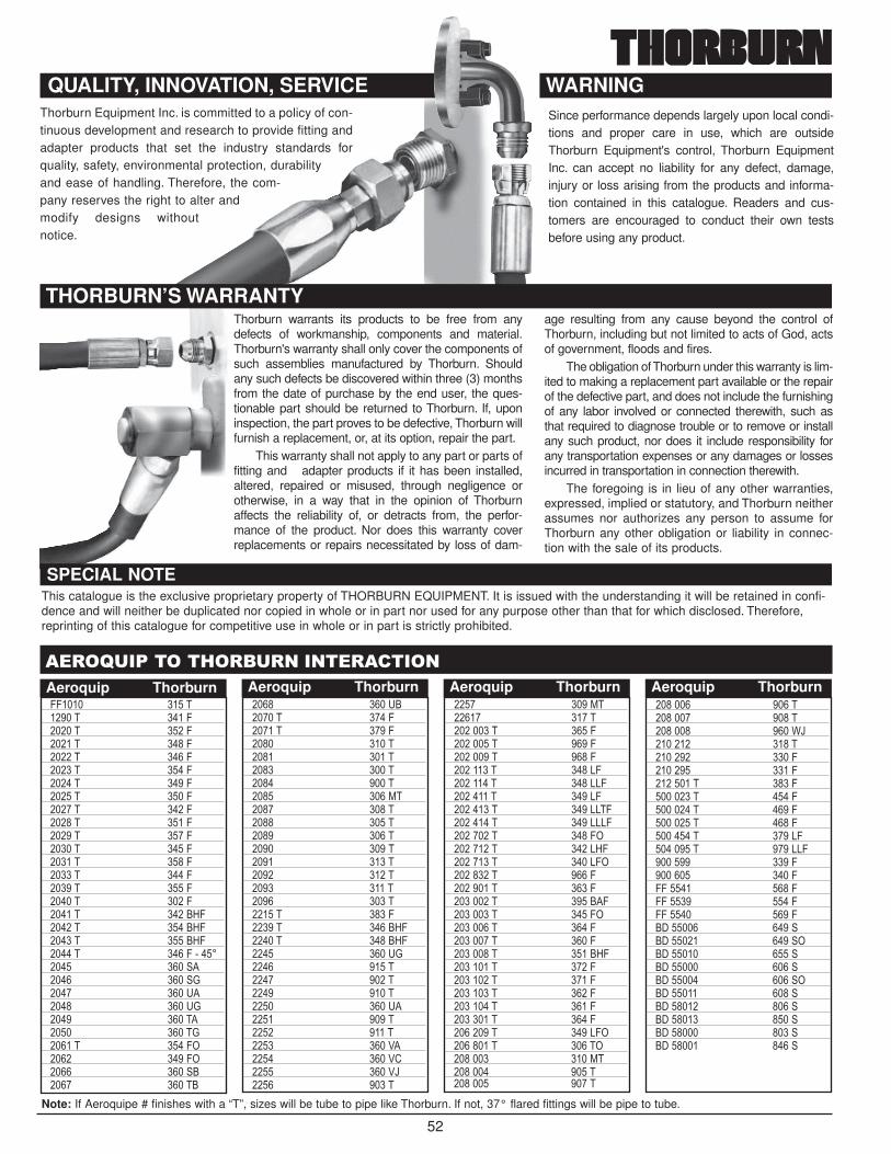
Thorburn Equipment Inc. is committed to a policy of con-tinuous development and research to provide fitting andadapter products that set the industry standards forquality, safety, environmental protection, durabilityand ease of handling. Therefore, the com-pany reserves the right to alter andmodify designs withoutnotice.
����=%�����#���%�� �����������
44���� ����������� ����4������ ����4������ ����4������ ����4������ ����4������ ����4������ ����4������ ����4������ ����4������ ����4������ ����4������ ����4������ ����4������ ����4������ ����4������ �����=4������ �����=4������ �����=4������ ����4���������� ���� ����� ���� J���� ����N����� ����NJ���� ���������� �����J������ ����4����� ����4����� ���� ����� ������
���� ����N������� ����4������ ����4���� ��������� ��������� ��������� ��������� ����*����� ��������� ��������� ��������� ��������� ��������� ��������� ��������� ����������� ����4������ �����=4������ �����=4���� ����NJ���� ��������� ��������� ��������� ����N����� ��������� ��������� ����C����� ����C/���� ����CL���� �����
���� ����*������ �������������� ����4��������� ����4��������� ����4��������� ����<4��������� ����<<4��������� ����<4��������� ����<<�4��������� ����<<<4��������� ����4���������� ����<=4��������� ����<4���������� ����4��������� ����4��������� ������4��������� ����4���������� ����4��������� ����4��������� �����=4��������� ����4��������� ����4��������� ����4��������� ����4��������� ����4��������� ����<4���������� ������������� ����*�������� ������������ �����
������� ������������ ������������ ����?L������� ������������� ����4�������� ����4��������� ����4��������� ����4��������� ����4��������� ����4��������� ����<4��������� ����<<4������� ����4������� ����444����� ����444����� ����444����� ����4� ������ ���� � ������ ���� �� ������ ���� � ������ ���� � ������ ���� �� ������ ���� � ������ ���� � ������ ���� � ������ ���� � ������ ����
Note: If Aeroquipe # finishes with a “T”, sizes will be tube to pipe like Thorburn. If not, 37° flared fittings will be pipe to tube.
Aeroquip Thorburn Aeroquip Thorburn Aeroquip Thorburn Aeroquip Thorburn
52
QUALITY, INNOVATION, SERVICE WARNING
This catalogue is the exclusive proprietary property of THORBURN EQUIPMENT. It is issued with the understanding it will be retained in confi-dence and will neither be duplicated nor copied in whole or in part nor used for any purpose other than that for which disclosed. Therefore,reprinting of this catalogue for competitive use in whole or in part is strictly prohibited.
THORBURN’S WARRANTY
Since performance depends largely upon local condi-tions and proper care in use, which are outsideThorburn Equipment's control, Thorburn EquipmentInc. can accept no liability for any defect, damage,injury or loss arising from the products and informa-tion contained in this catalogue. Readers and cus-tomers are encouraged to conduct their own testsbefore using any product.
Thorburn warrants its products to be free from anydefects of workmanship, components and material.Thorburn's warranty shall only cover the components ofsuch assemblies manufactured by Thorburn. Shouldany such defects be discovered within three (3) monthsfrom the date of purchase by the end user, the ques-tionable part should be returned to Thorburn. If, uponinspection, the part proves to be defective, Thorburn willfurnish a replacement, or, at its option, repair the part.
This warranty shall not apply to any part or parts offitting and adapter products if it has been installed,altered, repaired or misused, through negligence orotherwise, in a way that in the opinion of Thorburnaffects the reliability of, or detracts from, the perfor-mance of the product. Nor does this warranty coverreplacements or repairs necessitated by loss of dam-
age resulting from any cause beyond the control ofThorburn, including but not limited to acts of God, actsof government, floods and fires.
The obligation of Thorburn under this warranty is lim-ited to making a replacement part available or the repairof the defective part, and does not include the furnishingof any labor involved or connected therewith, such asthat required to diagnose trouble or to remove or installany such product, nor does it include responsibility forany transportation expenses or any damages or lossesincurred in transportation in connection therewith.
The foregoing is in lieu of any other warranties,expressed, implied or statutory, and Thorburn neitherassumes nor authorizes any person to assume forThorburn any other obligation or liability in connec-tion with the sale of its products.
SPECIAL NOTE

Thorburn Flex IncFlexible Piping Specialist
Thorburn is an innovative manufacturer of specialized engi-
neered flexible piping systems (i.e. custom hose assemblies,
expansion joints and precision machined couplings). Since
1954, Thorburn’s corporate mission, evolutions and business
philosophy have been custom driven and targeted to selected
niche applications in industries such as power generation
(both fossil fuel and nuclear), pulp and paper, petro-chemical,
aluminum smelting, shipbuilding, aerospace and pharmaceuti-
cals where Thorburn can achieve clear positions and sustain-
able technological and market share leadership.
Thorburn “O” Seal System is the universalanswer to troublesome fluid leakage problems.
Thorburn’s Industrial Standard 37° Flare TypeAdapter/Tube Fitting System
Thorburn’s Conversion Fitting System simplifiesconnections with Metric, JIS, DIN, GAZ and BSPpiping systems.
Thorburn Adapter/Tube Dimensions and
Pressure Compliance
■ SAE 516, 517, J514
■ Military Special Fittings MIL-F-18866
■ Military Standards MS 51500
■ ASME Section VIII B51, B31.1
Fitting & Connector Division
Shown is Jack Thorburn, who founded the companyin 1954, enjoying one of his passions, sailing.Unfortunately, Jack passed away on February 16th,1995. He will be sorely missed. The company’s lead-ership passed on to Jack’s eldest son, Robert, inSeptember 1994.
Thorburn’s Innovative Connection Technologies
Quality Certifications & Compliances■ ISO 9001
■ CSA CAN3 Z299.1
■ ASME Section III NCA-4000 NQA-1
■ CSA N-285.0
■ ASME Section VIII Division 1
■ CSA B.51

Thorburn Flex IncFlexible Piping Specialist
CALL NOW — LET US HELP YOU!MONTREAL HEAD OFFICEMARITIMES / WESTERN CANADA
THORBURN FLEX INC.Manufacturing Division
173 Oneida Drive
Pointe-Claire, Quebec, Canada H9R 1A9
Tel.: (514) 695-8710 Fax: (514) 695-8716
UNITED STATESTHORBURN FLEX INC.151 New Park Avenue
Hartford, Connecticut, USA 06106
Tel.: 1-800-363-6613
Fax: (514) 695-8716
TORONTO / ONTARIOTHORBURN FLEX INC.49-6A The Donway West, Suite 815
Don Mills, Ontario M3C 2E8
Tel.: (905) 715-7013
Fax: (905) 715-7816
PROVIDING EASY
SOLUTIONS TO
YOUR CONNECTOR
PROBLEMS
Toll free: 1-800-363-6613
Fitting & Connector Division
Related Documents