Thor CV31 Vehicle-Mount Computer Model CV31A User Manual

Welcome message from author
This document is posted to help you gain knowledge. Please leave a comment to let me know what you think about it! Share it to your friends and learn new things together.
Transcript
Thor CV31Vehicle-Mount ComputerModel CV31A
User Manual
ii Thor CV31 Vehicle-Mount Computer User Manual
Disclaimer
Honeywell International Inc. (“HII”) reserves the right to make changes in specifications and other information contained in this document without prior notice, and the reader should in all cases consult HII to determine whether any such changes have been made. The information in this publication does not represent a commitment on the part of HII.
HII shall not be liable for technical or editorial errors or omissions contained herein; nor for incidental or consequential damages resulting from the furnishing, performance, or use of this material.
This document contains proprietary information that is protected by copyright. All rights are reserved. No part of this document may be photocopied, reproduced, or translated into another language without the prior written consent of HII.
Trademarks
Wi-Fi is a registered certification mark of the Wi-Fi Alliance.
Microsoft, Windows, Windows Embedded Handheld, and the Windows logo are either trademarks or registered trademarks of Microsoft Corporation in the United States and/or other countries.
Bluetooth is a trademark of Bluetooth SIG, Inc., U.S.A.
microSD and microSDHC are trademarks or registered trademarks of SD-3C, LLC in the United States and/or other countries.
This product includes software developed by the OpenSSL Project for use in the OpenSSL Toolkit (www.openssl.org).
This product includes cryptographic software written by Eric Young ([email protected]).
Regex++ library © Copyright 1998-2001 by Dr. John MaddockPermission to use, copy, modify, distribute and sell this software and its documentation for any purpose is hereby granted without fee, provided that the above copyright notice appear in all copies and that both that copyright notice and this permission notice appear in supporting documentation. Dr John Maddock makes no representations about the suitability of this software for any purpose. It is provided “as is” without express or implied warranty.
Patents
For patent information, please refer to www.hsmpats.com.
© 2014 Honeywell International Inc. All rights reserved.
Contents
Thor CV31 Vehicle-Mount Computer User Manual iii
ContentsBefore You Begin. . . . . . . . . . . . . . . . . . . . . . . . . . . . . . . . . . . . . . . . . . . . . . . . . . . vii
Safety Information . . . . . . . . . . . . . . . . . . . . . . . . . . . . . . . . . . . . . . . . . . . viiGlobal Services and Support . . . . . . . . . . . . . . . . . . . . . . . . . . . . . . . . . . . vii
Warranty Information. . . . . . . . . . . . . . . . . . . . . . . . . . . . . . . . . . . viiWeb Support . . . . . . . . . . . . . . . . . . . . . . . . . . . . . . . . . . . . . . . . . viiSend Feedback . . . . . . . . . . . . . . . . . . . . . . . . . . . . . . . . . . . . . . . viiiTelephone Support . . . . . . . . . . . . . . . . . . . . . . . . . . . . . . . . . . . . viii
Who Should Read This Manual . . . . . . . . . . . . . . . . . . . . . . . . . . . . . . . . . viiiRelated Documents . . . . . . . . . . . . . . . . . . . . . . . . . . . . . . . . . . . . . . . . . . viii
1 About the Computer Features . . . . . . . . . . . . . . . . . . . . . . .1
About the Thor CV31 . . . . . . . . . . . . . . . . . . . . . . . . . . . . . . . . . . . . . . . . . . . . . . . . 2About the Buttons. . . . . . . . . . . . . . . . . . . . . . . . . . . . . . . . . . . . . . . . . . . . . 3
About the Power Button . . . . . . . . . . . . . . . . . . . . . . . . . . . . . . . . . 4Configure the Power Button . . . . . . . . . . . . . . . . . . . . . . . . . . . . . . 4About the Power Options . . . . . . . . . . . . . . . . . . . . . . . . . . . . . . . . 4Configure the Power Options Menu . . . . . . . . . . . . . . . . . . . . . . . . 6
About the Ports and Connectors . . . . . . . . . . . . . . . . . . . . . . . . . . . . . . . . . 6About the Status LEDs. . . . . . . . . . . . . . . . . . . . . . . . . . . . . . . . . . . . . . . . . 9
How to Supply Power to the CV31 . . . . . . . . . . . . . . . . . . . . . . . . . . . . . . . . . . . . . 10About the Backup Battery . . . . . . . . . . . . . . . . . . . . . . . . . . . . . . . . . . . . . 11Check the Status of the Backup Battery. . . . . . . . . . . . . . . . . . . . . . . . . . . 11Disable Backup Battery Charging . . . . . . . . . . . . . . . . . . . . . . . . . . . . . . . 12
How to Mount the CV31 . . . . . . . . . . . . . . . . . . . . . . . . . . . . . . . . . . . . . . . . . . . . . 12
How to Connect a Scanner . . . . . . . . . . . . . . . . . . . . . . . . . . . . . . . . . . . . . . . . . . . 12About Serial Scanners . . . . . . . . . . . . . . . . . . . . . . . . . . . . . . . . . . . . . . . . 13Connect a Serial Scanner . . . . . . . . . . . . . . . . . . . . . . . . . . . . . . . . . . . . . 13About USB Scanners . . . . . . . . . . . . . . . . . . . . . . . . . . . . . . . . . . . . . . . . . 14Connect a USB Scanner . . . . . . . . . . . . . . . . . . . . . . . . . . . . . . . . . . . . . . 14
How to Connect a Headset . . . . . . . . . . . . . . . . . . . . . . . . . . . . . . . . . . . . . . . . . . . 14
How to Change the Volume. . . . . . . . . . . . . . . . . . . . . . . . . . . . . . . . . . . . . . . . . . . 15
Connect an External Keyboard . . . . . . . . . . . . . . . . . . . . . . . . . . . . . . . . . . . . . . . . 16
About External Antennas . . . . . . . . . . . . . . . . . . . . . . . . . . . . . . . . . . . . . . . . . . . . 16
Contents
iv Thor CV31 Vehicle-Mount Computer User Manual
Install an External Antenna . . . . . . . . . . . . . . . . . . . . . . . . . . . . . . . . . . . . . . . . . . . 17
About the Bar Code Slot Reader. . . . . . . . . . . . . . . . . . . . . . . . . . . . . . . . . . . . . . . 17
Configure the Bar Code Slot Reader . . . . . . . . . . . . . . . . . . . . . . . . . . . . . . . . . . . 18
Install a microSD Card . . . . . . . . . . . . . . . . . . . . . . . . . . . . . . . . . . . . . . . . . . . . . . 18
CV31 Accessories. . . . . . . . . . . . . . . . . . . . . . . . . . . . . . . . . . . . . . . . . . . . . . . . . . 20
2 About the User Interface and Installed Applications. . . .23
About the User Interface . . . . . . . . . . . . . . . . . . . . . . . . . . . . . . . . . . . . . . . . . . . . . 24
About the Touch Screen . . . . . . . . . . . . . . . . . . . . . . . . . . . . . . . . . . . . . . . . . . . . . 24About Screen Gestures . . . . . . . . . . . . . . . . . . . . . . . . . . . . . . . . . . . . . . . 24Calibrate the Touch Screen . . . . . . . . . . . . . . . . . . . . . . . . . . . . . . . . . . . . 25
Applications Installed on the Computer. . . . . . . . . . . . . . . . . . . . . . . . . . . . . . . . . . 25
Downloadable Applications for the Computer . . . . . . . . . . . . . . . . . . . . . . . . . . . . . 26About HTML5 Browser . . . . . . . . . . . . . . . . . . . . . . . . . . . . . . . . . . . . . . . . 26About Launcher for Windows . . . . . . . . . . . . . . . . . . . . . . . . . . . . . . . . . . . 26About Intermec Terminal Emulator. . . . . . . . . . . . . . . . . . . . . . . . . . . . . . . 27About SmartSystems . . . . . . . . . . . . . . . . . . . . . . . . . . . . . . . . . . . . . . . . . 27
3 Configure the Computer. . . . . . . . . . . . . . . . . . . . . . . . . . .29
How to Configure the Computer . . . . . . . . . . . . . . . . . . . . . . . . . . . . . . . . . . . . . . . 30
About Intermec Settings on the Computer . . . . . . . . . . . . . . . . . . . . . . . . . . . . . . . 30Start Intermec Settings . . . . . . . . . . . . . . . . . . . . . . . . . . . . . . . . . . . . . . . 31About the Structure of Intermec Settings . . . . . . . . . . . . . . . . . . . . . . . . . . 32How to Navigate in Intermec Settings . . . . . . . . . . . . . . . . . . . . . . . . . . . . 36Enable Intermec Settings Password. . . . . . . . . . . . . . . . . . . . . . . . . . . . . . 36Restore Default Settings . . . . . . . . . . . . . . . . . . . . . . . . . . . . . . . . . . . . . . 37Hide Menu Items in Intermec Settings . . . . . . . . . . . . . . . . . . . . . . . . . . . . 37
Configure the Computer Remotely with SmartSystems . . . . . . . . . . . . . . . . . . . . . 38

Thor CV31 Vehicle-Mount Computer User Manual v
About Network Communications. . . . . . . . . . . . . . . . . . . . . . . . . . . . . . . . . . . . . . . 38About 802.11 Radio Communications . . . . . . . . . . . . . . . . . . . . . . . . . . . . 38About Bluetooth Communications . . . . . . . . . . . . . . . . . . . . . . . . . . . . . . . 38
Configure Bluetooth Communications. . . . . . . . . . . . . . . . . . . . . . 39Connect a Bluetooth Scanner with the Quick Connect Bar Code . 39Connect a Bluetooth Scanner with the Wireless Scanning App . . 40Connect to a Bluetooth Printer . . . . . . . . . . . . . . . . . . . . . . . . . . . 40
About Wireless Security . . . . . . . . . . . . . . . . . . . . . . . . . . . . . . . . . . . . . . . . . . . . . 41Load a Certificate . . . . . . . . . . . . . . . . . . . . . . . . . . . . . . . . . . . . . . . . . . . . 41Select a Funk Security Profile . . . . . . . . . . . . . . . . . . . . . . . . . . . . . . . . . . 42
Configure WPA or WPA2 Enterprise (802.1x) Security with Funk Security . . . . . . . . . . . . . . . . . . . . . . . . . . . . . . . . . . . . . . 42
Configure WPA or WPA2 Personal (PSK) Security with Funk Security . . . . . . . . . . . . . . . . . . . . . . . . . . . . . . . . . . . . . . 43
Configure 802.1x Security with Funk Security. . . . . . . . . . . . . . . . 44Configure LEAP Security with Funk Security . . . . . . . . . . . . . . . . 44Configure Static WEP Security with Funk Security . . . . . . . . . . . . 45Use Open (No Security) Associations with Funk Security. . . . . . . 45
4 Manage the Computer . . . . . . . . . . . . . . . . . . . . . . . . . . . .47
How to Manage the Computer in Your Network . . . . . . . . . . . . . . . . . . . . . . . . . . . 48How to Manage the Computer with CloneNGo . . . . . . . . . . . . . . . . . . . . . 48How to Manage the Computer with SmartSystems . . . . . . . . . . . . . . . . . . 48How to Manage the Computer with Third-Party Software . . . . . . . . . . . . . 49
How to Develop and Install Applications . . . . . . . . . . . . . . . . . . . . . . . . . . . . . . . . . 49How to Package Your Application. . . . . . . . . . . . . . . . . . . . . . . . . . . . . . . . 49Install Applications with SmartSystems . . . . . . . . . . . . . . . . . . . . . . . . . . . 50Install Applications with Microsoft Synchronization Software. . . . . . . . . . . 50Install Applications with a microSD Card . . . . . . . . . . . . . . . . . . . . . . . . . . 51Install Applications with a USB Device. . . . . . . . . . . . . . . . . . . . . . . . . . . . 51How to Launch Applications Automatically. . . . . . . . . . . . . . . . . . . . . . . . . 51
How to Update the System Software . . . . . . . . . . . . . . . . . . . . . . . . . . . . . . . . . . . 52Update the Computer with SmartSystems . . . . . . . . . . . . . . . . . . . . . . . . . 52Update the Computer with a microSD Card . . . . . . . . . . . . . . . . . . . . . . . . 53
vi Thor CV31 Vehicle-Mount Computer User Manual
5 Troubleshoot and Maintain the Computer . . . . . . . . . . . .55
How to Troubleshoot the Computer. . . . . . . . . . . . . . . . . . . . . . . . . . . . . . . . . . . . . 56Wi-Fi Connection Problems . . . . . . . . . . . . . . . . . . . . . . . . . . . . . . . . . . . . 56How to Check Wi-Fi Network Status . . . . . . . . . . . . . . . . . . . . . . . . . . . . . 57802.1x Security Problems . . . . . . . . . . . . . . . . . . . . . . . . . . . . . . . . . . . . . 57Problems Reading Bar Codes . . . . . . . . . . . . . . . . . . . . . . . . . . . . . . . . . . 59Problems Using the Computer . . . . . . . . . . . . . . . . . . . . . . . . . . . . . . . . . . 61
Call Product Support . . . . . . . . . . . . . . . . . . . . . . . . . . . . . . . . . . . . . . . . . . . . . . . . 62Find Your Configuration Number . . . . . . . . . . . . . . . . . . . . . . . . . . . . . . . . 62Find Your Operating System Version . . . . . . . . . . . . . . . . . . . . . . . . . . . . . 62
How to Restart the Computer . . . . . . . . . . . . . . . . . . . . . . . . . . . . . . . . . . . . . . . . . 63Reboot the Computer . . . . . . . . . . . . . . . . . . . . . . . . . . . . . . . . . . . . . . . . . 63Reset the Computer . . . . . . . . . . . . . . . . . . . . . . . . . . . . . . . . . . . . . . . . . . 63
Clean the Computer . . . . . . . . . . . . . . . . . . . . . . . . . . . . . . . . . . . . . . . . . . . . . . . . 63
A Specifications . . . . . . . . . . . . . . . . . . . . . . . . . . . . . . . . . .65
Physical and Environmental Specifications. . . . . . . . . . . . . . . . . . . . . . . . . . . . . . . 66Screen Specifications. . . . . . . . . . . . . . . . . . . . . . . . . . . . . . . . . . . . . . . . . 67Keyboard Options. . . . . . . . . . . . . . . . . . . . . . . . . . . . . . . . . . . . . . . . . . . . 67Bar Code Symbologies. . . . . . . . . . . . . . . . . . . . . . . . . . . . . . . . . . . . . . . . 67
Pin Assignments . . . . . . . . . . . . . . . . . . . . . . . . . . . . . . . . . . . . . . . . . . . . . . . . . . . 68COM 1 and COM 3 Ports . . . . . . . . . . . . . . . . . . . . . . . . . . . . . . . . . . . . . . 68USB Port . . . . . . . . . . . . . . . . . . . . . . . . . . . . . . . . . . . . . . . . . . . . . . . . . . 69Power Connector . . . . . . . . . . . . . . . . . . . . . . . . . . . . . . . . . . . . . . . . . . . . 70
B Device Settings . . . . . . . . . . . . . . . . . . . . . . . . . . . . . . . . .71
Default Configuration. . . . . . . . . . . . . . . . . . . . . . . . . . . . . . . . . . . . . . . . . . . . . . . . 72Default Configuration . . . . . . . . . . . . . . . . . . . . . . . . . . . . . . . . . . . . . . . . . 72RFID. . . . . . . . . . . . . . . . . . . . . . . . . . . . . . . . . . . . . . . . . . . . . . . . . . . . . . 75Communications. . . . . . . . . . . . . . . . . . . . . . . . . . . . . . . . . . . . . . . . . . . . . 77Device Settings . . . . . . . . . . . . . . . . . . . . . . . . . . . . . . . . . . . . . . . . . . . . . 79Core Messaging Service . . . . . . . . . . . . . . . . . . . . . . . . . . . . . . . . . . . . . . 80Device Monitor . . . . . . . . . . . . . . . . . . . . . . . . . . . . . . . . . . . . . . . . . . . . . . 80Virtual Wedge. . . . . . . . . . . . . . . . . . . . . . . . . . . . . . . . . . . . . . . . . . . . . . . 81

Before You Begin
Thor CV31 Vehicle-Mount Computer User Manual vii
Before You BeginThis section provides you with safety information, technical support information, and sources for additional product information.
Safety Information Your safety is extremely important. Read and follow all warnings and cautions in this document before handling and operating Intermec equipment. You can be seriously injured, and equipment and data can be damaged if you do not follow the safety warnings and cautions.
This section explains how to identify and understand cautions and notes that are in this document.
Global Services and Support
Warranty InformationTo understand the warranty for your Honeywell product, visit the Honeywell website at www.honeywellaidc.com and click Resources > Warranty.
Web SupportVisit the Honeywell website at www.honeywellaidc.com to download our current manuals (in PDF).
Visit the Knowledge Base (www.hsmknowledgebase.com) to access thousands of immediate solutions, or go to the Technical Support Portal (www.hsmsupportportal.com) to request support. To contact our technical support team directly, fill out an online support form at www.hsmcontactsupport.com.
A caution alerts you to an operating procedure, practice, condition, or statement that must be strictly observed to prevent equipment damage or destruction, or corruption or loss of data.
Note: Notes either provide extra information about a topic or contain special instructions for handling a particular condition or set of circumstances.
Before You Begin
viii Thor CV31 Vehicle-Mount Computer User Manual
Send FeedbackYour feedback is crucial to the continual improvement of our documentation. To provide feedback about this manual, please contact the Intermec Technical Communications department directly at [email protected].
Telephone SupportFor our latest contact information, please check our website at www.honeywellaidc.com/locations.
Who Should Read This ManualThis manual is for the person who is responsible for installing, configuring, and maintaining the CV31.
This manual provides you with information about the features of the CV31, and how to install, configure, operate, maintain, and troubleshoot the computer.
Before you work with the CV31, you should be familiar with your network and general networking terms, such as IP address.
Related DocumentsThe Honeywell website at www.honeywellaidc.com contains our documents (as .pdf files) that you can download for free.
To download documents1 Visit the Honeywell website at www.honeywellaidc.com.
2 Click Products.
3 Use the Products menu to navigate to your product page. For example, to find the CV31 product page, click Vehicle-Mount Computers > Thor CV31 Vehicle-Mount Computer.

1
1About the Computer Features
This chapter introduces the Thor™ CV31 Vehicle-Mount Computer with Microsoft® Windows® Embedded Compact 7 (CE 7). Use this chapter to learn about basic features and functions of the computer, as well as available accessories.
Chapter 1 — About the Computer Features
2 Thor CV31 Vehicle-Mount Computer User Manual
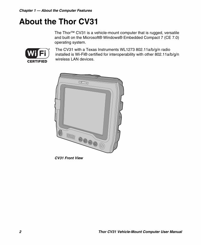
About the Thor CV31The Thor™ CV31 is a vehicle-mount computer that is rugged, versatile and built on the Microsoft® Windows® Embedded Compact 7 (CE 7.0) operating system.
CV31 Front View
The CV31 with a Texas Instruments WL1273 802.11a/b/g/n radio installed is Wi-Fi® certified for interoperability with other 802.11a/b/g/n wireless LAN devices.
Chapter 1 — About the Computer Features
Thor CV31 Vehicle-Mount Computer User Manual 3
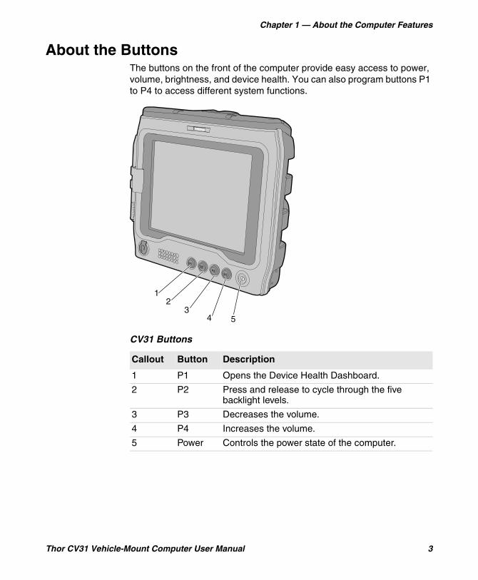
About the ButtonsThe buttons on the front of the computer provide easy access to power, volume, brightness, and device health. You can also program buttons P1 to P4 to access different system functions.
CV31 Buttons
Callout Button Description
1 P1 Opens the Device Health Dashboard.
2 P2 Press and release to cycle through the five backlight levels.
3 P3 Decreases the volume.
4 P4 Increases the volume.
5 Power Controls the power state of the computer.
5
12
34
Chapter 1 — About the Computer Features
4 Thor CV31 Vehicle-Mount Computer User Manual
About the Power ButtonThe Power button controls the power state of the computer.
You can also use Intermec Settings to disable the Power button or configure the button to perform the actions available from the Power Options menu.
Configure the Power ButtonYou can disable the Power button or configure the button to perform the actions available from the Power Options menu.
1 On your computer, start Intermec Settings.
2 Tap Device Settings > Power Management > Power Button > Power button behavior.
3 Select the action that you want to be performed when you press the Power button.
4 To save your changes, tap OK.
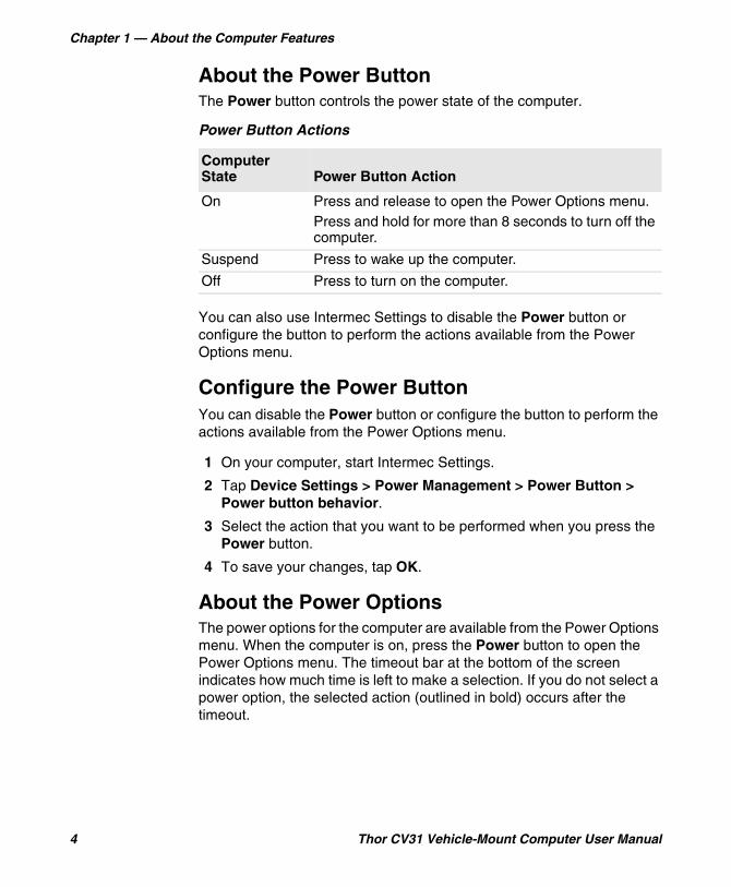
About the Power OptionsThe power options for the computer are available from the Power Options menu. When the computer is on, press the Power button to open the Power Options menu. The timeout bar at the bottom of the screen indicates how much time is left to make a selection. If you do not select a power option, the selected action (outlined in bold) occurs after the timeout.
Power Button Actions
Computer State Power Button Action
On Press and release to open the Power Options menu.Press and hold for more than 8 seconds to turn off the computer.
Suspend Press to wake up the computer.
Off Press to turn on the computer.
Chapter 1 — About the Computer Features
Thor CV31 Vehicle-Mount Computer User Manual 5
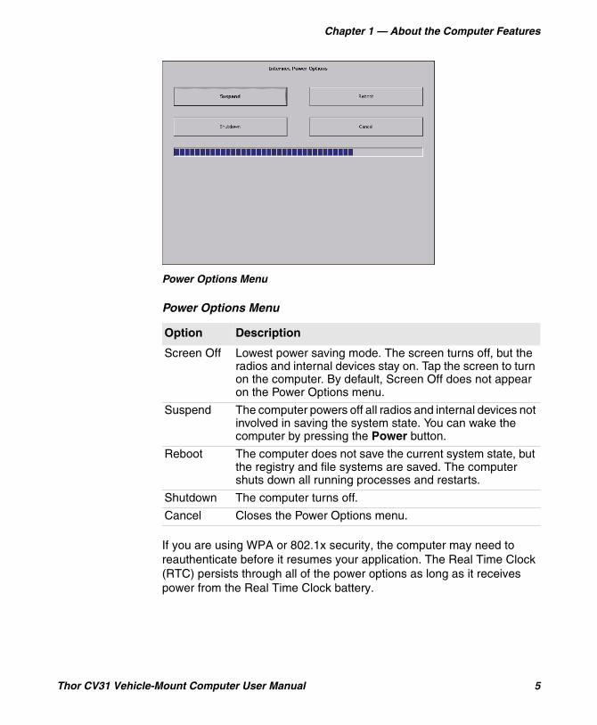
Power Options Menu
If you are using WPA or 802.1x security, the computer may need to reauthenticate before it resumes your application. The Real Time Clock (RTC) persists through all of the power options as long as it receives power from the Real Time Clock battery.
Power Options Menu
Option Description
Screen Off Lowest power saving mode. The screen turns off, but the radios and internal devices stay on. Tap the screen to turn on the computer. By default, Screen Off does not appear on the Power Options menu.
Suspend The computer powers off all radios and internal devices not involved in saving the system state. You can wake the computer by pressing the Power button.
Reboot The computer does not save the current system state, but the registry and file systems are saved. The computer shuts down all running processes and restarts.
Shutdown The computer turns off.
Cancel Closes the Power Options menu.
Chapter 1 — About the Computer Features
6 Thor CV31 Vehicle-Mount Computer User Manual
Configure the Power Options MenuYou can enable or disable the Power Options menu, determine which options appear on the menu, and set the amount of time you have to make a selection.
1 On your computer, start Intermec Settings.
2 Tap Device Settings > Power Management > Power Button > Power Button Screen > Screen Options Displayed.
3 Configure the Power Options menu:
• To enable or disable the Power Options menu, tap Enable power button screen.
• To select the options that appear on the Power Options menu, tap Screen Options Displayed.
• To set the amount of time to make a selection (from 1 to 20 seconds), tap Screen timeout (seconds).
4 To save your changes, tap OK.
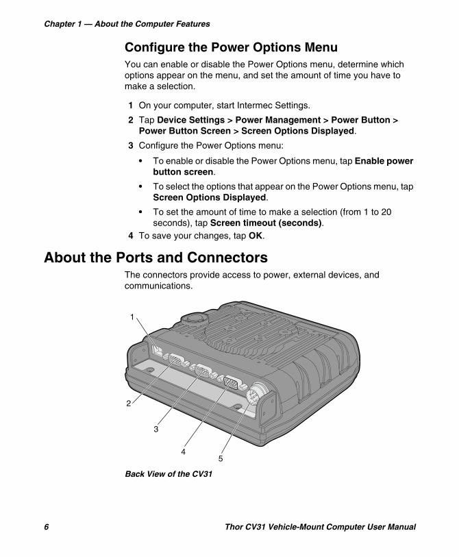
About the Ports and ConnectorsThe connectors provide access to power, external devices, and communications.
Back View of the CV31
45
3
2
1
Chapter 1 — About the Computer Features
Thor CV31 Vehicle-Mount Computer User Manual 7
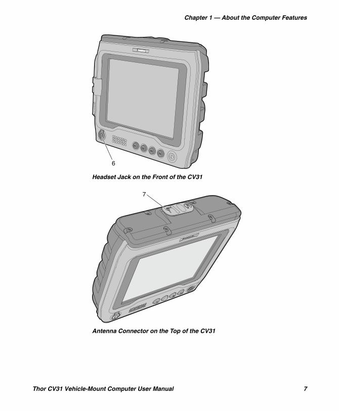
Headset Jack on the Front of the CV31
Antenna Connector on the Top of the CV31
6
7
Chapter 1 — About the Computer Features
8 Thor CV31 Vehicle-Mount Computer User Manual
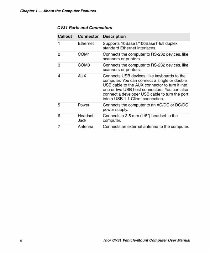
CV31 Ports and Connectors
Callout Connector Description
1 Ethernet Supports 10BaseT/100BaseT full duplex standard Ethernet interfaces.
2 COM1 Connects the computer to RS-232 devices, like scanners or printers.
3 COM3 Connects the computer to RS-232 devices, like scanners or printers.
4 AUX Connects USB devices, like keyboards to the computer. You can connect a single or double USB cable to the AUX connector to turn it into one or two USB host connectors. You can also connect a developer USB cable to turn the port into a USB 1.1 Client connection.
5 Power Connects the computer to an AC/DC or DC/DC power supply.
6 Headset Jack
Connects a 3.5 mm (1/8") headset to the computer.
7 Antenna Connects an external antenna to the computer.
Chapter 1 — About the Computer Features
Thor CV31 Vehicle-Mount Computer User Manual 9
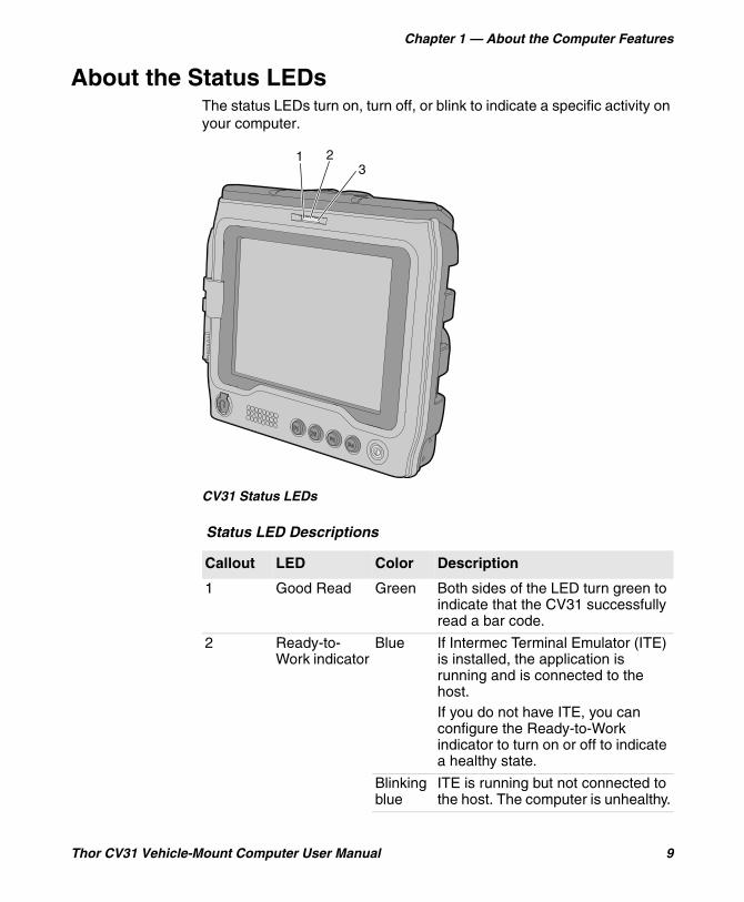
About the Status LEDsThe status LEDs turn on, turn off, or blink to indicate a specific activity on your computer.
CV31 Status LEDs
Status LED Descriptions
Callout LED Color Description
1 Good Read Green Both sides of the LED turn green to indicate that the CV31 successfully read a bar code.
2 Ready-to-Work indicator
Blue If Intermec Terminal Emulator (ITE) is installed, the application is running and is connected to the host.If you do not have ITE, you can configure the Ready-to-Work indicator to turn on or off to indicate a healthy state.
Blinking blue
ITE is running but not connected to the host. The computer is unhealthy.
1 23

Chapter 1 — About the Computer Features
10 Thor CV31 Vehicle-Mount Computer User Manual
How to Supply Power to the CV31The accessories you use to supply power to the CV31 depends on whether you want to replace a CV30 and keep your existing wiring or perform a new installation:
• To replace a CV30 and keep your existing wiring, you need to purchase an adapter cable (P/N VE027-8024-C0).
• To perform a new installation, you need to know the electrical rating of your CV31 and the vehicle you are installing it on to determine which power supply to use.
Off ITE is not installed or not running. The computer is healthy.
3 Battery Status Steady orange
The battery is outside the allowable charging temperature range of 0 °C to 40 °C (32 °F to 104 °F). Charging will resume when the battery temperature returns to within the acceptable range.
Blinking orange
There is a battery error. The battery is not charging because it is missing, faulty, or there is a bad connection.
Blinking red
The CV31 is not connected to external power, and the battery is very low. The computer will go into Suspend mode soon. Charge or replace the battery.
Status LED Descriptions (continued)
Callout LED Color Description
Note: The AC power supply for the CV31 is different than the AC power supply for the CV30. Do not use the CV30 power supply with the CV31.

Chapter 1 — About the Computer Features
Thor CV31 Vehicle-Mount Computer User Manual 11
*The connector for the CV31 AC power supply is different than the one for the CV30. You cannot use the CV31 power supply with a CV30.
About the Backup BatteryIf the CV31 is disconnected from external power, the backup battery can keep the CV31 running in a network connected state for up to 30 minutes. When power is restored, the CV31 continues normal operation.
An internal charger automatically charges the backup battery (within 8 hours) when the CV31 is connected to external power.
Check the Status of the Backup BatteryCheck the status of the backup battery to make sure that it is functioning properly.
1 Tap Start > Settings > Control Panel.
2 Double tap Power.
The battery status appears on the Battery tab.
CV31 Power Supply Options for a New Installation
Installation Electrical Requirement
CV31 Electrical Rating Use This Power Supply
100-240 VAC,50-60 Hz
12 V, 2.1 A or 9-36 V, 5.1 A
AC Power Supply (P/N 203-955-001)*
Vehicle: 9-36 VDC
9-36 V, 5.1 A Thor CV31/CV61 Direct Wiring Kit (P/N 203-950-001)
Vehicle: Over 36 VDC, up to 96 VDC
12 V, 2.1 A or 9-36 V, 5.1 A
Universal Vehicle Power Supply Kit (P/N 203-950-002) with cable P/N VE027-8024-C0
Note: The battery temperature must be with in the acceptable range of 0 °C to 40 °C (32 °F to 104 °F) to charge.
Chapter 1 — About the Computer Features
12 Thor CV31 Vehicle-Mount Computer User Manual
Disable Backup Battery ChargingIf you use the CV31 in a cold environment for an extended period of time, the backup battery temperature may fall below the required temperature for charging (0 °C, 32 °F). To prevent data loss, the default state of the CV31 is to not start if the backup battery does not have sufficient charge. If you need to start a CV31 that has a low battery but is connected to external power in a cold environment, you can disable this setting.
1 Start Intermec Settings.
2 Tap Device Settings > Boot Charging Options.
3 Select Disable charging during startup.
How to Mount the CV31Use a Honeywell approved mounting accessory to mount the CV31:
• Desktop Mounting Kit (P/N 805-815-001)• Vehicle Mounting Kit with a 1.5-inch (C-size) (P/N 805-813-001) or
2.25-inch (D-size) (P/N 805-814-001) RAM ball• Wall Mounting Kit (P/N VE011-2006)• Mounting Screw Kit (P/N 213-043-001) to mount the CV31 to an
existing 1.5-inch (C-size) or 2.25-inch (D-size) RAM ball
How to Connect a ScannerYou can connect a scanner to the computer with one of these connectors:
• Serial• USB
You can also connect a Bluetooth scanner through Bluetooth communications.
Caution: If the CV31 is disconnected from external power and the backup battery does not have sufficient charge, data may be lost or corrupted.
Note: Power to the COM ports is disabled when power is not supplied to the CV31 (the vehicle is turned off).
Chapter 1 — About the Computer Features
Thor CV31 Vehicle-Mount Computer User Manual 13
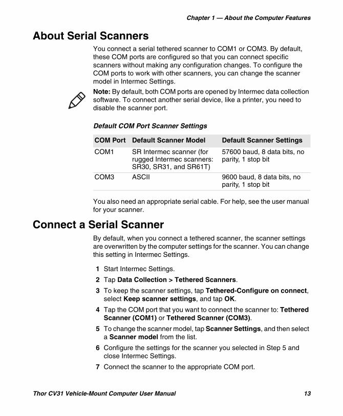
About Serial ScannersYou connect a serial tethered scanner to COM1 or COM3. By default, these COM ports are configured so that you can connect specific scanners without making any configuration changes. To configure the COM ports to work with other scanners, you can change the scanner model in Intermec Settings.
You also need an appropriate serial cable. For help, see the user manual for your scanner.
Connect a Serial ScannerBy default, when you connect a tethered scanner, the scanner settings are overwritten by the computer settings for the scanner. You can change this setting in Intermec Settings.
1 Start Intermec Settings.
2 Tap Data Collection > Tethered Scanners.
3 To keep the scanner settings, tap Tethered-Configure on connect, select Keep scanner settings, and tap OK.
4 Tap the COM port that you want to connect the scanner to: Tethered Scanner (COM1) or Tethered Scanner (COM3).
5 To change the scanner model, tap Scanner Settings, and then select a Scanner model from the list.
6 Configure the settings for the scanner you selected in Step 5 and close Intermec Settings.
7 Connect the scanner to the appropriate COM port.
Note: By default, both COM ports are opened by Intermec data collection software. To connect another serial device, like a printer, you need to disable the scanner port.
Default COM Port Scanner Settings
COM Port Default Scanner Model Default Scanner Settings
COM1 SR Intermec scanner (for rugged Intermec scanners: SR30, SR31, and SR61T)
57600 baud, 8 data bits, no parity, 1 stop bit
COM3 ASCII 9600 baud, 8 data bits, no parity, 1 stop bit
Chapter 1 — About the Computer Features
14 Thor CV31 Vehicle-Mount Computer User Manual
About USB ScannersTo use a USB scanner with the CV31, you need to configure the scanner as a Human Interface Device (HID). When HID is enabled, scanned bar code data is sent directly to an active window as if the data came from a keyboard. You need to configure any data handling settings in the scanner with the scanner manufacturer’s configuration bar codes. For help, see the scanner user manual.
Connect a USB ScannerConnect a USB tethered scanner to the AUX port.
1 Connect an appropriate USB cable to the AUX port on the computer.
2 Connect the scanner to the USB cable.
How to Connect a HeadsetUse one of these methods to connect a headset or audio device:
• Plug a 3.5 mm (1/8") headset into the headset jack. Note that the headset jack on the CV31 is not the same size as the headset jack on the CV30 (2.5 mm, 3/32").
• Use the Bluetooth Audio applet.• Pair a Vocollect Bluetooth headset with the near-field communication
(NFC) radio.

Chapter 1 — About the Computer Features
Thor CV31 Vehicle-Mount Computer User Manual 15
Location of the NFC Radio
How to Change the VolumeThe computer volume controls the sounds you hear when you tap the screen or scan bar codes with an external scanner.
NFC
Methods to Change the Volume
Method Description
Front panel buttons Use the volume up and volume down buttons on the front panel.
Control panel Tap Start > Settings > Control Panel, and then double-tap Volume & Sounds.
Intermec Settings Start Intermec Settings and go to Device Settings > Sounds > Beeper and voice.
Chapter 1 — About the Computer Features
16 Thor CV31 Vehicle-Mount Computer User Manual
Connect an External KeyboardYou can attach a compact or standard external keyboard to make data entry easier. To attach a standard keyboard, you also need an appropriate USB cable.
1 Mount the keyboard. For help, see the installation instructions that ship with the mounting kit.
2 Connect the keyboard to the CV31:
• For compact keyboards, connect the keyboard cable to the AUX port on the computer.
• For standard keyboards, connect an appropriate USB cable to the computer, and then connect the keyboard to the USB cable.
About External AntennasUse an external antenna to increase the signal strength of the wireless radio in the CV31. You can mount the antenna on a wall, forklift, or other flat surface with hardware or adhesive-backed hook and loop fastener material.
For most fixed installations, you should mount the antenna in a vertically-polarized position with the cable from the antenna parallel to the floor and ceiling. However, you may need to experiment with antenna position to find an orientation that provides the best antenna performance. Use the ISpyWiFi application that ships on the computer to determine which antenna position provides the best signal strength.
Chapter 1 — About the Computer Features
Thor CV31 Vehicle-Mount Computer User Manual 17
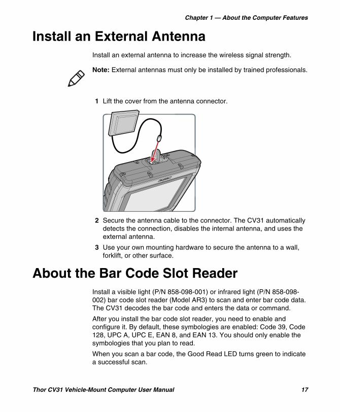
Install an External AntennaInstall an external antenna to increase the wireless signal strength.
1 Lift the cover from the antenna connector.
2 Secure the antenna cable to the connector. The CV31 automatically detects the connection, disables the internal antenna, and uses the external antenna.
3 Use your own mounting hardware to secure the antenna to a wall, forklift, or other surface.
About the Bar Code Slot ReaderInstall a visible light (P/N 858-098-001) or infrared light (P/N 858-098-002) bar code slot reader (Model AR3) to scan and enter bar code data. The CV31 decodes the bar code and enters the data or command.
After you install the bar code slot reader, you need to enable and configure it. By default, these symbologies are enabled: Code 39, Code 128, UPC A, UPC E, EAN 8, and EAN 13. You should only enable the symbologies that you plan to read.
When you scan a bar code, the Good Read LED turns green to indicate a successful scan.
Note: External antennas must only be installed by trained professionals.

Chapter 1 — About the Computer Features
18 Thor CV31 Vehicle-Mount Computer User Manual
Configure the Bar Code Slot ReaderIf you installed the bar code slot reader (Model AR3) accessory, you need to enable and configure it before you can use it.
1 Start Intermec Settings.
2 Tap Data Collection > Tethered Scanner (COM1 or COM3) > Scanner Settings.
3 Tap Scanner Model.
4 From the list, select ID Tech Slot Scanner.
5 Select Enable Scanner Port.
6 Tap OK.
7 Tap Data Collection > Tethered Scanner (COM1 or COM3) > Symbologies.
8 Only enable the symbologies that you plan to read.
Install a microSD CardUse a microSD card to increase file storage or install software. The computer resets when you install or remove a microSD card.
1 To turn off the computer, press the Power button and tap Suspend.
2 Disconnect the power cord from the computer.
3 Use a Phillips screwdriver to remove the six screws that secure the cover.
(x6)
Chapter 1 — About the Computer Features
Thor CV31 Vehicle-Mount Computer User Manual 19
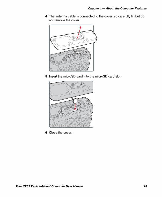
4 The antenna cable is connected to the cover, so carefully lift but do not remove the cover.
5 Insert the microSD card into the microSD card slot.
6 Close the cover.
Chapter 1 — About the Computer Features
20 Thor CV31 Vehicle-Mount Computer User Manual
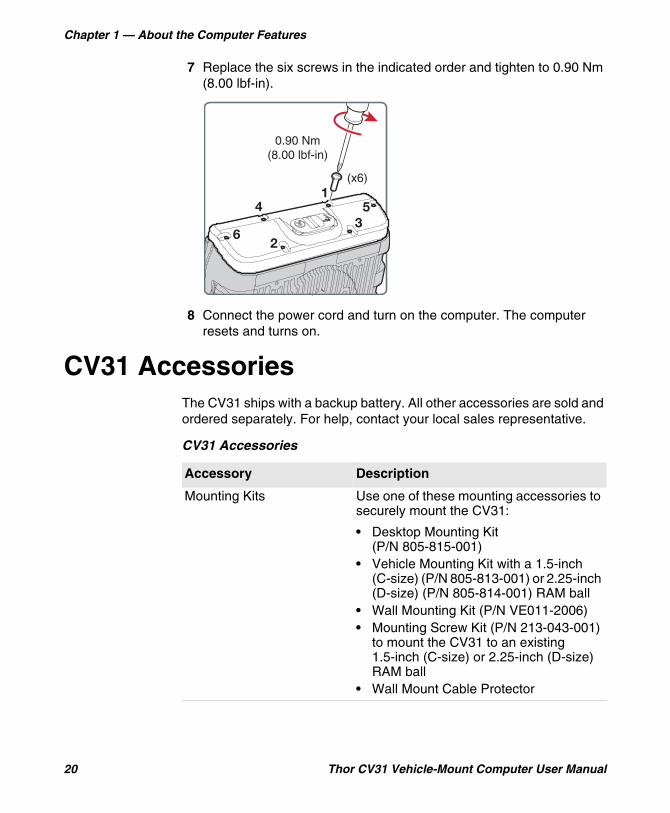
7 Replace the six screws in the indicated order and tighten to 0.90 Nm (8.00 lbf-in).
8 Connect the power cord and turn on the computer. The computer resets and turns on.
CV31 AccessoriesThe CV31 ships with a backup battery. All other accessories are sold and ordered separately. For help, contact your local sales representative.
(x6)
0.90 Nm(8.00 lbf-in)
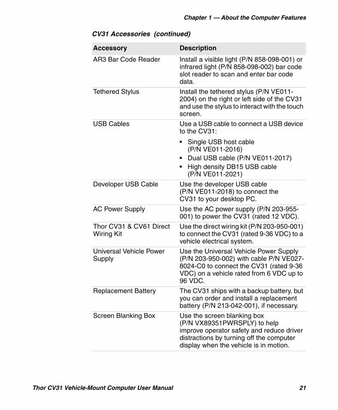
CV31 Accessories
Accessory Description
Mounting Kits Use one of these mounting accessories to securely mount the CV31:
• Desktop Mounting Kit (P/N 805-815-001)
• Vehicle Mounting Kit with a 1.5-inch (C-size) (P/N 805-813-001) or 2.25-inch (D-size) (P/N 805-814-001) RAM ball
• Wall Mounting Kit (P/N VE011-2006)• Mounting Screw Kit (P/N 213-043-001)
to mount the CV31 to an existing 1.5-inch (C-size) or 2.25-inch (D-size) RAM ball
• Wall Mount Cable Protector
Chapter 1 — About the Computer Features
Thor CV31 Vehicle-Mount Computer User Manual 21
AR3 Bar Code Reader Install a visible light (P/N 858-098-001) or infrared light (P/N 858-098-002) bar code slot reader to scan and enter bar code data.
Tethered Stylus Install the tethered stylus (P/N VE011-2004) on the right or left side of the CV31 and use the stylus to interact with the touch screen.
USB Cables Use a USB cable to connect a USB device to the CV31:
• Single USB host cable (P/N VE011-2016)
• Dual USB cable (P/N VE011-2017)• High density DB15 USB cable
(P/N VE011-2021)
Developer USB Cable Use the developer USB cable (P/N VE011-2018) to connect the CV31 to your desktop PC.
AC Power Supply Use the AC power supply (P/N 203-955-001) to power the CV31 (rated 12 VDC).
Thor CV31 & CV61 Direct Wiring Kit
Use the direct wiring kit (P/N 203-950-001) to connect the CV31 (rated 9-36 VDC) to a vehicle electrical system.
Universal Vehicle Power Supply
Use the Universal Vehicle Power Supply (P/N 203-950-002) with cable P/N VE027-8024-C0 to connect the CV31 (rated 9-36 VDC) on a vehicle rated from 6 VDC up to 96 VDC.
Replacement Battery The CV31 ships with a backup battery, but you can order and install a replacement battery (P/N 213-042-001), if necessary.
Screen Blanking Box Use the screen blanking box (P/N VX89351PWRSPLY) to help improve operator safety and reduce driver distractions by turning off the computer display when the vehicle is in motion.
CV31 Accessories (continued)
Accessory Description
Chapter 1 — About the Computer Features
22 Thor CV31 Vehicle-Mount Computer User Manual
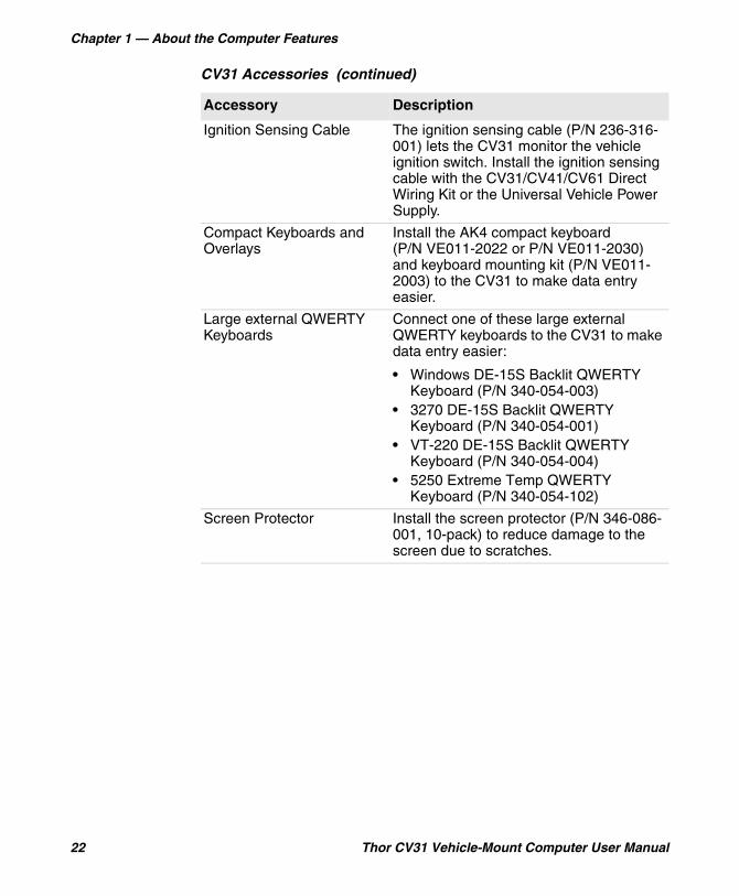
Ignition Sensing Cable The ignition sensing cable (P/N 236-316-001) lets the CV31 monitor the vehicle ignition switch. Install the ignition sensing cable with the CV31/CV41/CV61 Direct Wiring Kit or the Universal Vehicle Power Supply.
Compact Keyboards and Overlays
Install the AK4 compact keyboard (P/N VE011-2022 or P/N VE011-2030) and keyboard mounting kit (P/N VE011-2003) to the CV31 to make data entry easier.
Large external QWERTY Keyboards
Connect one of these large external QWERTY keyboards to the CV31 to make data entry easier:
• Windows DE-15S Backlit QWERTY Keyboard (P/N 340-054-003)
• 3270 DE-15S Backlit QWERTY Keyboard (P/N 340-054-001)
• VT-220 DE-15S Backlit QWERTY Keyboard (P/N 340-054-004)
• 5250 Extreme Temp QWERTY Keyboard (P/N 340-054-102)
Screen Protector Install the screen protector (P/N 346-086-001, 10-pack) to reduce damage to the screen due to scratches.
CV31 Accessories (continued)
Accessory Description

23
2About the User Interface and Installed Applications
Use this chapter to learn about the Microsoft® Windows® Embedded Compact 7 (CE 7) user interface and how to interact with the screen. You can also use this chapter to learn about the applications installed on your computer, as well as additional applications you can download.
Chapter 2 — About the User Interface and Installed Applications
24 Thor CV31 Vehicle-Mount Computer User Manual
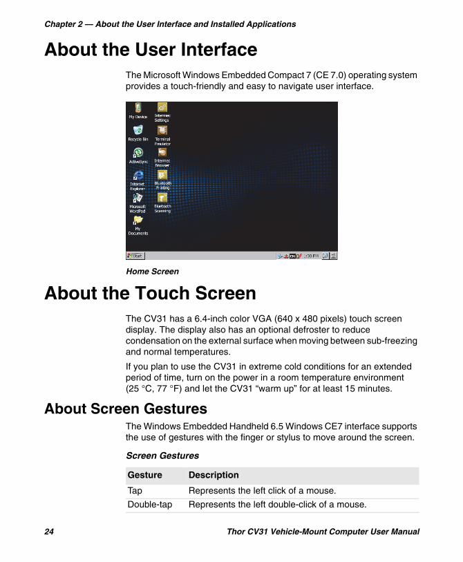
About the User InterfaceThe Microsoft Windows Embedded Compact 7 (CE 7.0) operating system provides a touch-friendly and easy to navigate user interface.
Home Screen
About the Touch ScreenThe CV31 has a 6.4-inch color VGA (640 x 480 pixels) touch screen display. The display also has an optional defroster to reduce condensation on the external surface when moving between sub-freezing and normal temperatures.
If you plan to use the CV31 in extreme cold conditions for an extended period of time, turn on the power in a room temperature environment (25 °C, 77 °F) and let the CV31 “warm up” for at least 15 minutes.
About Screen GesturesThe Windows Embedded Handheld 6.5 Windows CE7 interface supports the use of gestures with the finger or stylus to move around the screen.
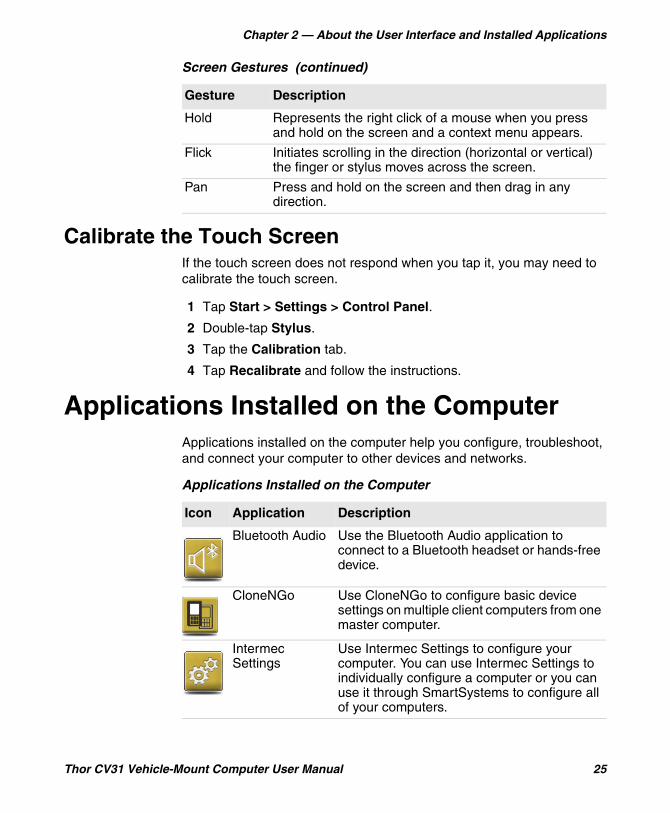
Screen Gestures
Gesture Description
Tap Represents the left click of a mouse.
Double-tap Represents the left double-click of a mouse.
Chapter 2 — About the User Interface and Installed Applications
Thor CV31 Vehicle-Mount Computer User Manual 25
Calibrate the Touch ScreenIf the touch screen does not respond when you tap it, you may need to calibrate the touch screen.
1 Tap Start > Settings > Control Panel.
2 Double-tap Stylus.
3 Tap the Calibration tab.
4 Tap Recalibrate and follow the instructions.
Applications Installed on the ComputerApplications installed on the computer help you configure, troubleshoot, and connect your computer to other devices and networks.
Hold Represents the right click of a mouse when you press and hold on the screen and a context menu appears.
Flick Initiates scrolling in the direction (horizontal or vertical) the finger or stylus moves across the screen.
Pan Press and hold on the screen and then drag in any direction.
Screen Gestures (continued)
Gesture Description
Applications Installed on the Computer
Icon Application Description
Bluetooth Audio Use the Bluetooth Audio application to connect to a Bluetooth headset or hands-free device.
CloneNGo Use CloneNGo to configure basic device settings on multiple client computers from one master computer.
Intermec Settings
Use Intermec Settings to configure your computer. You can use Intermec Settings to individually configure a computer or you can use it through SmartSystems to configure all of your computers.
Chapter 2 — About the User Interface and Installed Applications
26 Thor CV31 Vehicle-Mount Computer User Manual
Downloadable Applications for the Computer
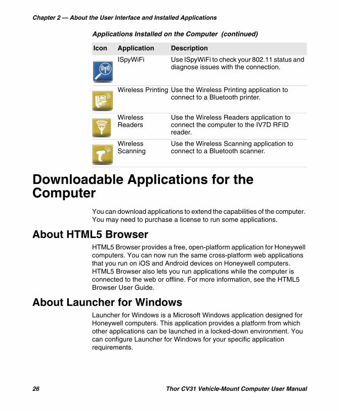
You can download applications to extend the capabilities of the computer. You may need to purchase a license to run some applications.
About HTML5 BrowserHTML5 Browser provides a free, open-platform application for Honeywell computers. You can now run the same cross-platform web applications that you run on iOS and Android devices on Honeywell computers. HTML5 Browser also lets you run applications while the computer is connected to the web or offline. For more information, see the HTML5 Browser User Guide.
About Launcher for WindowsLauncher for Windows is a Microsoft Windows application designed for Honeywell computers. This application provides a platform from which other applications can be launched in a locked-down environment. You can configure Launcher for Windows for your specific application requirements.
ISpyWiFi Use ISpyWiFi to check your 802.11 status and diagnose issues with the connection.
Wireless Printing Use the Wireless Printing application to connect to a Bluetooth printer.
Wireless Readers
Use the Wireless Readers application to connect the computer to the IV7D RFID reader.
Wireless Scanning
Use the Wireless Scanning application to connect to a Bluetooth scanner.
Applications Installed on the Computer (continued)
Icon Application Description
Chapter 2 — About the User Interface and Installed Applications
Thor CV31 Vehicle-Mount Computer User Manual 27
You can download and use Launcher for Windows for a 60-day evaluation period. When the evaluation period ends, you need to purchase a license. For help, contact your local Honeywell representative.
About Intermec Terminal EmulatorIntermec Terminal Emulator (ITE) is Intermec’s popular terminal emulation client designed for enterprise-level data collection. In a single client, ITE supports multiple emulation protocols. Its features include session persistence, remote management and configuration, and multiple security options. ITE provides a consistent user interface and a common menu structure (Intermec Settings), simplifying the use and management of applications running on Intermec mobile computers.
You can download and use ITE for a 60-day demo period. During the demo period, a demo mode message box appears each time you run ITE. Press Enter to close the message box. When the demo period ends, you need to purchase a license. For help, contact your local Honeywell representative.
About SmartSystemsIntermec SmartSystems is an easy-to-use centralized software platform. With SmartSystems, IT Administrators and Integrators can perform hands-free provisioning and deploy and manage computers.
SmartSystems provides a consistent way to manage computers located on-site or remotely to maximize IT resources and lower the total cost of ownership for your data collection equipment. You can download SmartSystems at no charge from the Intermec website at www.intermec.com/SmartSystems.

Chapter 2 — About the User Interface and Installed Applications
28 Thor CV31 Vehicle-Mount Computer User Manual
29
3Configure the Computer
Use this chapter to learn about the available methods for configuring your computer and how to use Intermec Settings. You can also use this chapter to learn how to configure network communications and wireless security.
Chapter 3 — Configure the Computer
30 Thor CV31 Vehicle-Mount Computer User Manual
How to Configure the ComputerYou can configure many parameters on the computer such as the bar code symbologies it decodes or the network settings. The values you set for these parameters determine how the computer operates.
There are several ways to configure the computer:
• Directly on the computer. You can use Intermec Settings directly on the computer to change only the settings on that computer.
• Remotely using Intermec SmartSystems. With SmartSystems, you can remotely configure all of your mobile computers as well as other SmartSystems-enabled Intermec devices and peripherals.
• Using a third-party device management product that supports the computer and Intermec Settings, such as Soti MobiControl or Wavelink Avalanche.
• Using configuration bundles that you create with SmartSystems.
About Intermec Settings on the ComputerUse Intermec Settings to configure parameters for Intermec applications on the computer, as well as some device-specific parameters like volume. You can configure parameters for important functions like data collection and communications. You can also password protect Intermec Settings to prevent users from making changes to the configuration settings.
Chapter 3 — Configure the Computer
Thor CV31 Vehicle-Mount Computer User Manual 31
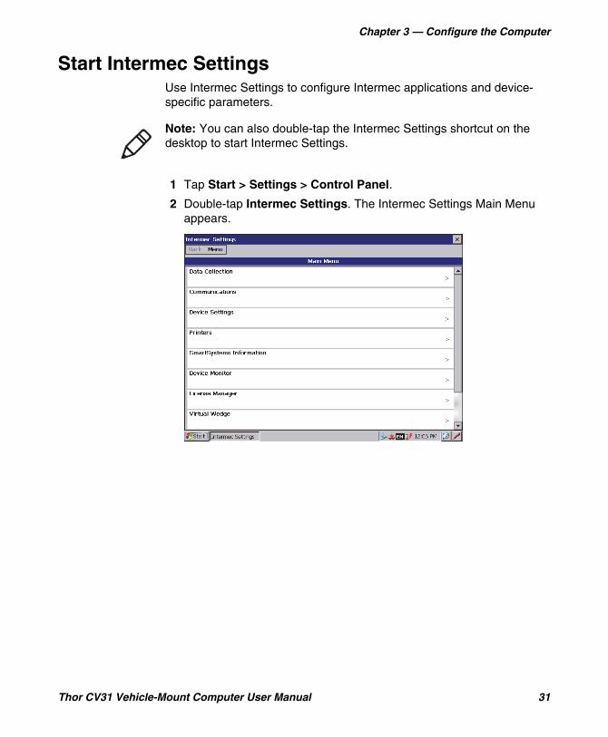
Start Intermec SettingsUse Intermec Settings to configure Intermec applications and device-specific parameters.
1 Tap Start > Settings > Control Panel.
2 Double-tap Intermec Settings. The Intermec Settings Main Menu appears.
Note: You can also double-tap the Intermec Settings shortcut on the desktop to start Intermec Settings.
Chapter 3 — Configure the Computer
32 Thor CV31 Vehicle-Mount Computer User Manual
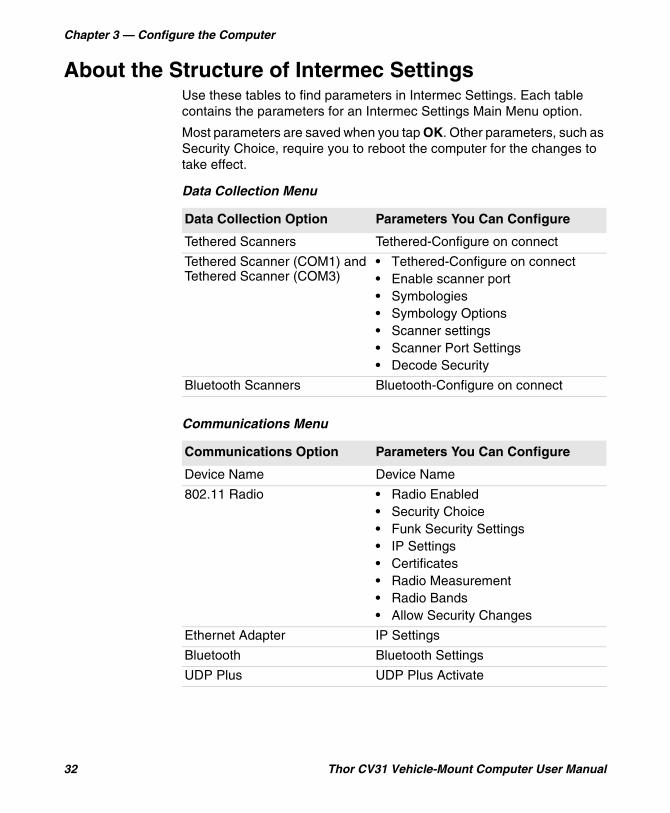
About the Structure of Intermec SettingsUse these tables to find parameters in Intermec Settings. Each table contains the parameters for an Intermec Settings Main Menu option.
Most parameters are saved when you tap OK. Other parameters, such as Security Choice, require you to reboot the computer for the changes to take effect.
Data Collection Menu
Data Collection Option Parameters You Can Configure
Tethered Scanners Tethered-Configure on connect
Tethered Scanner (COM1) and Tethered Scanner (COM3)
• Tethered-Configure on connect• Enable scanner port• Symbologies• Symbology Options• Scanner settings• Scanner Port Settings• Decode Security
Bluetooth Scanners Bluetooth-Configure on connect
Communications Menu
Communications Option Parameters You Can Configure
Device Name Device Name
802.11 Radio • Radio Enabled• Security Choice• Funk Security Settings• IP Settings• Certificates• Radio Measurement• Radio Bands• Allow Security Changes
Ethernet Adapter IP Settings
Bluetooth Bluetooth Settings
UDP Plus UDP Plus Activate
Chapter 3 — Configure the Computer
Thor CV31 Vehicle-Mount Computer User Manual 33
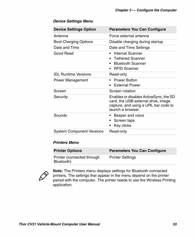
Device Settings Menu
Device Settings Option Parameters You Can Configure
Antenna Force external antenna
Boot Charging Options Disable charging during startup
Date and Time Date and Time Settings
Good Read • Internal Scanner• Tethered Scanner• Bluetooth Scanner• RFID Scanner
IDL Runtime Versions Read-only
Power Management • Power Button• External Power
Screen Screen rotation
Security Enables or disables ActiveSync, the SD card, the USB external drive, image capture, and using a URL bar code to launch a browser.
Sounds • Beeper and voice• Screen taps• Key clicks
System Component Versions Read-only
Printers Menu
Printer Options Parameters You Can Configure
Printer (connected through Bluetooth)
Printer Settings
Note: The Printers menu displays settings for Bluetooth connected printers. The settings that appear in the menu depend on the printer paired with the computer. The printer needs to use the Wireless Printing application.
Chapter 3 — Configure the Computer
34 Thor CV31 Vehicle-Mount Computer User Manual
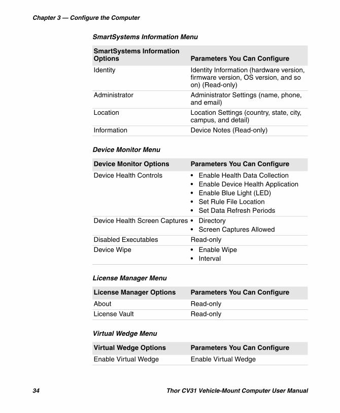
SmartSystems Information Menu
SmartSystems Information Options Parameters You Can Configure
Identity Identity Information (hardware version, firmware version, OS version, and so on) (Read-only)
Administrator Administrator Settings (name, phone, and email)
Location Location Settings (country, state, city, campus, and detail)
Information Device Notes (Read-only)
Device Monitor Menu
Device Monitor Options Parameters You Can Configure
Device Health Controls • Enable Health Data Collection• Enable Device Health Application• Enable Blue Light (LED)• Set Rule File Location• Set Data Refresh Periods
Device Health Screen Captures • Directory• Screen Captures Allowed
Disabled Executables Read-only
Device Wipe • Enable Wipe• Interval
License Manager Menu
License Manager Options Parameters You Can Configure
About Read-only
License Vault Read-only
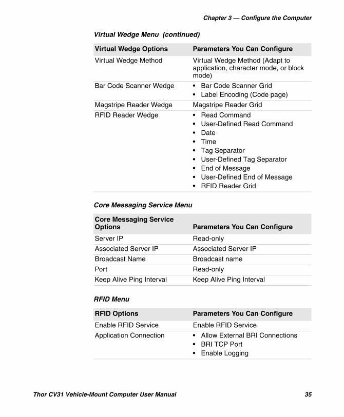
Virtual Wedge Menu
Virtual Wedge Options Parameters You Can Configure
Enable Virtual Wedge Enable Virtual Wedge
Chapter 3 — Configure the Computer
Thor CV31 Vehicle-Mount Computer User Manual 35
Virtual Wedge Method Virtual Wedge Method (Adapt to application, character mode, or block mode)
Bar Code Scanner Wedge • Bar Code Scanner Grid• Label Encoding (Code page)
Magstripe Reader Wedge Magstripe Reader Grid
RFID Reader Wedge • Read Command• User-Defined Read Command• Date• Time• Tag Separator• User-Defined Tag Separator• End of Message• User-Defined End of Message• RFID Reader Grid
Core Messaging Service Menu
Core Messaging Service Options Parameters You Can Configure
Server IP Read-only
Associated Server IP Associated Server IP
Broadcast Name Broadcast name
Port Read-only
Keep Alive Ping Interval Keep Alive Ping Interval
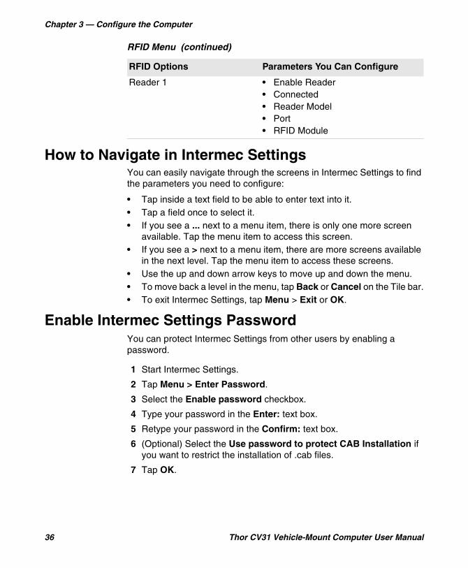
RFID Menu
RFID Options Parameters You Can Configure
Enable RFID Service Enable RFID Service
Application Connection • Allow External BRI Connections• BRI TCP Port• Enable Logging
Virtual Wedge Menu (continued)
Virtual Wedge Options Parameters You Can Configure
Chapter 3 — Configure the Computer
36 Thor CV31 Vehicle-Mount Computer User Manual
How to Navigate in Intermec SettingsYou can easily navigate through the screens in Intermec Settings to find the parameters you need to configure:
• Tap inside a text field to be able to enter text into it.• Tap a field once to select it.• If you see a ... next to a menu item, there is only one more screen
available. Tap the menu item to access this screen.• If you see a > next to a menu item, there are more screens available
in the next level. Tap the menu item to access these screens.• Use the up and down arrow keys to move up and down the menu. • To move back a level in the menu, tap Back or Cancel on the Tile bar.• To exit Intermec Settings, tap Menu > Exit or OK.
Enable Intermec Settings PasswordYou can protect Intermec Settings from other users by enabling a password.
1 Start Intermec Settings.
2 Tap Menu > Enter Password.
3 Select the Enable password checkbox.
4 Type your password in the Enter: text box.
5 Retype your password in the Confirm: text box.
6 (Optional) Select the Use password to protect CAB Installation if you want to restrict the installation of .cab files.
7 Tap OK.
Reader 1 • Enable Reader• Connected• Reader Model• Port• RFID Module
RFID Menu (continued)
RFID Options Parameters You Can Configure
Chapter 3 — Configure the Computer
Thor CV31 Vehicle-Mount Computer User Manual 37
Restore Default SettingsThe easiest way to restore default settings on your computer is to use Intermec Settings. You can restore all default settings on your computer or restore default settings for a specific menu item in Intermec Settings.
1 Start Intermec Settings.
2 Restore the default settings:
• To restore all default settings, tap Menu > Restore all Defaults.
• To restore default settings for one menu item, navigate to the menu and tap Menu > Restore Menu Defaults.
3 When prompted, tap Yes to restore the default settings.
If you are prompted to refresh the computer, tap Yes.
Hide Menu Items in Intermec SettingsYou can hide menu items in Intermec Settings if you do not want other users to access them. When you restore default settings in Intermec Settings, hidden items are not restored. When you back up settings using the SmartSystems console, hidden items are not backed up.
1 Navigate to the menu item that you want to hide.
2 Tap and hold the menu item. A list appears.
3 Select Hide Menu Item.
4 When you are prompted to hide the menu, tap Yes.
Note: When you restore default settings, only the settings for visible menu items are restored. The settings for hidden menu items are not affected.
Note: To restore all hidden items in all menus, tap Menu > Unhide All Items.
Chapter 3 — Configure the Computer
38 Thor CV31 Vehicle-Mount Computer User Manual
Configure the Computer Remotely with SmartSystems
You can use Intermec Settings from a SmartSystems console to remotely configure all the Intermec computers. For help using Intermec Settings, click Help > Contents. For information on all the parameters in Intermec Settings, see the Intermec Settings Command Reference Manual.
1 In the SmartSystems console, select a computer and then right-click on it. A list appears.
2 Select Start Intermec Settings.
3 Configure the settings you want to change. As you select parameters, help for each parameter appears in the upper right pane.
4 When you are done making changes, select File > Save Settings.
About Network CommunicationsYou can use the mobile computer in your wireless or wired data collection network. You can connect your computer using:
• 802.11 radio communications.• Ethernet communications.• Bluetooth communications.• USB and serial communications.
About 802.11 Radio CommunicationsThe computer has an 801.11a/b/g/n radio to transfer data using wireless communications. Before you configure radio communications, you need to set up your wireless network, including your access points.
About Bluetooth CommunicationsThe computer is Bluetooth-enabled, which lets you connect to these Bluetooth devices:
• Scanners• Printers• Audio devices• Wireless readers
Chapter 3 — Configure the Computer
Thor CV31 Vehicle-Mount Computer User Manual 39
By default, the Bluetooth radio is on. The Bluetooth radio maintains its current state through a warm or cold boot and maintains virtual COM ports. But, if you clean boot the computer, you need to recreate pairings with Bluetooth devices.
Configure Bluetooth CommunicationsBefore you can connect to a Bluetooth device, you need to configure the Bluetooth radio so that your computer is discoverable and connectable.
1 Start Intermec Settings.
2 Tap Communications > Bluetooth.
3 Make sure that the Power is On and Discoverable and Connectable are both Enabled.
4 Exit Intermec Settings.
Other Bluetooth devices can discover and connect to your computer.
Connect a Bluetooth Scanner with the Quick Connect Bar CodeScan the Quick Connect bar code to easily connect your CV31 to a Bluetooth scanner, such as an Intermec SF51 or SR61. By default, when you connect a Bluetooth scanner, the scanner settings are overwritten by the computer settings for the scanner. You can change this setting in Intermec Settings.
1 To keep the scanner settings, start Intermec Settings:
a Tap Data Collection > Bluetooth Scanners.
b Tap BT-Configure on connect, select Keep scanner settings, and tap OK.
c Tap Back twice to return to the main menu.
d Exit Intermec Settings.
2 With your Bluetooth scanner, scan the Quick Connect bar code on either side of the computer.
3 When prompted, enter the passcode for your scanner. For Intermec Bluetooth scanners, the default passcode is 0000.
The scanner pairs with your computer.
Chapter 3 — Configure the Computer
40 Thor CV31 Vehicle-Mount Computer User Manual
Connect a Bluetooth Scanner with the Wireless Scanning AppUse the Wireless Scanning app to discover and connect to Bluetooth scanners within range of your computer. By default, when you connect a Bluetooth scanner, the scanner settings are overwritten by the computer settings for the scanner. You can change this setting in Intermec Settings.
1 To keep the scanner settings, start Intermec Settings:
a Tap Data Collection > Bluetooth Scanners.
b Tap BT-Configure on connect, select Keep scanner settings, and tap OK.
c Tap Back twice to return to the main menu.
d Exit Intermec Settings.
2 Tap Start > Settings > Control Panel.
3 Double-tap Wireless Scanning.
4 Tap Add Device.
5 Select Quick Connect, Search, or Manual and tap Next.
6 Follow the instructions to add a wireless scanner.
Connect to a Bluetooth PrinterUse the Wireless Printing application to connect to a Bluetooth printer.
1 Tap Start > Settings > Control Panel.
2 Double-tap Wireless Printing.
3 Tap Search to find a printer, or tap Manual to enter a device address.
4 Follow the instructions.
5 (Optional) Tap Print Test. The printer prints a test page.

Chapter 3 — Configure the Computer
Thor CV31 Vehicle-Mount Computer User Manual 41
About Wireless SecurityThe computer provides these security solutions for your wireless network:
• Wi-Fi Protected Access 2 (WPA2™)• Wi-Fi Protected Access (WPA)• 802.1x• LEAP (Funk security only)• WEPHoneywell recommends WPA2 security with PSK (Personal) or 802.1x (Enterprise) key management.
Before you set security, you need to enable the radio, set the date, and set the SSID on your computer. To use 802.1x security, you need to load a root certificate on your computer. To use transport layer security (TLS) with 802.1x security, you also need to load a user certificate.
Load a CertificateTo use transport layer security (TLS) with 802.1x security, you need a unique client certificate on the computer and a trusted root certificate authority (CA) certificate.
1 Start Intermec Settings.
2 Select Communications > 802.11 Radio > Certificates.
3 Tap Import Certificates.
4 To import a certificate chain:
a Tap the Import PFX tab.
b Next to the Select pfx to import field, tap <<<.
c Find and select the root certificate.
d If necessary, enter the Password of pfx.
e Tap Import Certificate.

Chapter 3 — Configure the Computer
42 Thor CV31 Vehicle-Mount Computer User Manual
5 To import user and root certificates from a Microsoft IAS server:
a Tap Web Enrollment.
b To log on to the server, enter the User, Password, and Server (IP Address).
c Tap OK.
d When you are prompted to load the root certificate, tap OK.
e When the message box appears to let you know the certificate has been added, tap OK.
Select a Funk Security ProfileYou can define up to four profiles for Funk security. Different profiles let your computer communicate in different networks without having to change all your security settings. For example, you may want to set up one profile for the manufacturing floor and one for the warehouse. By default, the active profile is Profile 1.
1 Start Intermec Settings.
2 Select Communications > 802.11 Radio > Funk Security.
3 Tap a profile to expand it.
4 (Optional) In the Profile Label text box, enter a meaningful name for your profile.
5 Configure your security settings. For help, see the next sections.
6 Repeat Steps 3 through 5 for each profile you want to define.
7 To set the active profile, tap Active Profile and select a profile from the list.
8 Save your settings.
Configure WPA or WPA2 Enterprise (802.1x) Security with Funk SecurityBefore you set WPA-802.1x or WPA2-802.1x security with Funk, you need to configure your authentication server and authenticators. To use TLS protocol, you also need to load a user and root certificate. On your computer, you need to enable the radio and set the date.
1 Start Intermec Settings.
2 Select Communications > 802.11 Radio > Funk Security.
3 Select a Funk security profile to configure.
Chapter 3 — Configure the Computer
Thor CV31 Vehicle-Mount Computer User Manual 43
4 Enter the SSID.
5 For Association, select WPA or WPA2.
The default encryption is TKIP or AES, respectively.
6 For 8021x, select TTLS, PEAP, EAP-FAST, or TLS.
7 If you selected TTLS, PEAP, or EAP-FAST:
a For Prompt for Credentials, select Enter credentials now.
b Enter a User Name and User Password.
8 If you selected TLS, enter a User Name and Subject Name.
9 For Validate Server Certificate, select Yes.
10 Tap OK.
Configure WPA or WPA2 Personal (PSK) Security with Funk SecurityBefore you set WPA or WPA2 Personal (PSK) security, you need to know the pre-shared key for your access point or passphrase for your authenticator. On your computer, you need to enable the radio and set the date.
1 Start Intermec Settings.
2 Select Communications > 802.11 Radio > Funk Security.
3 Select a Funk security profile to configure.
4 Enter the SSID.
5 For Association, select WPA or WPA2.
The default encryption is TKIP or AES, respectively.
6 For 8021x, select None.
7 For Pre-Shared Key, enter the pre-shared key or passphrase:
• Enter the pre-shared key (0x followed by 32 hexadecimal pairs) for your access point.
• Enter the passphrase (8 to 63 ASCII characters) for your authenticator. The computer internally converts the passphrase to a pre-shared key.
8 Tap OK.
Chapter 3 — Configure the Computer
44 Thor CV31 Vehicle-Mount Computer User Manual
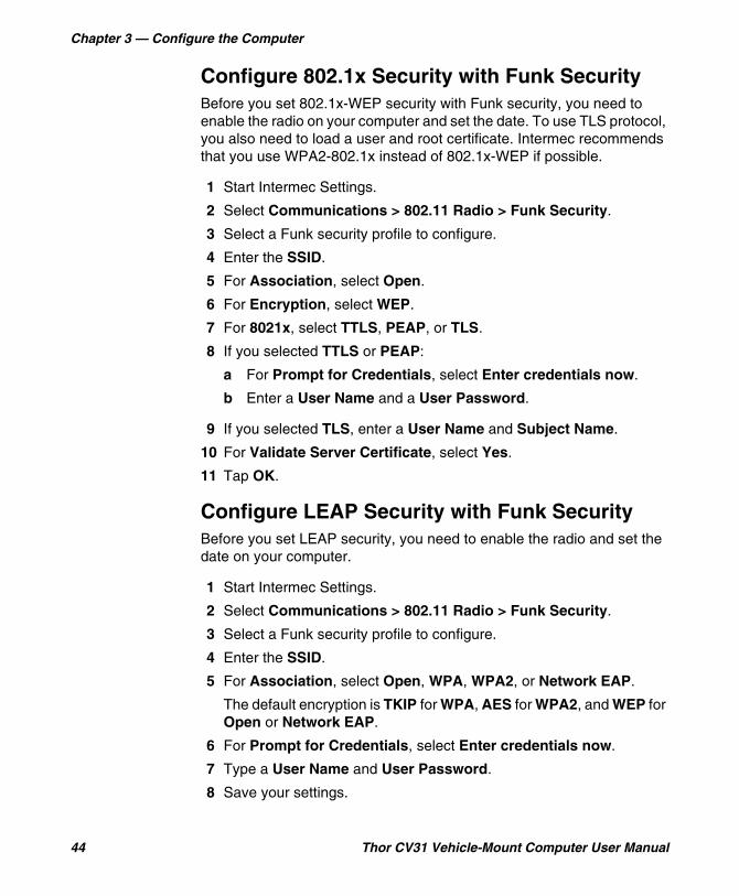
Configure 802.1x Security with Funk SecurityBefore you set 802.1x-WEP security with Funk security, you need to enable the radio on your computer and set the date. To use TLS protocol, you also need to load a user and root certificate. Intermec recommends that you use WPA2-802.1x instead of 802.1x-WEP if possible.
1 Start Intermec Settings.
2 Select Communications > 802.11 Radio > Funk Security.
3 Select a Funk security profile to configure.
4 Enter the SSID.
5 For Association, select Open.
6 For Encryption, select WEP.
7 For 8021x, select TTLS, PEAP, or TLS.
8 If you selected TTLS or PEAP:
a For Prompt for Credentials, select Enter credentials now.
b Enter a User Name and a User Password.
9 If you selected TLS, enter a User Name and Subject Name.
10 For Validate Server Certificate, select Yes.
11 Tap OK.
Configure LEAP Security with Funk SecurityBefore you set LEAP security, you need to enable the radio and set the date on your computer.
1 Start Intermec Settings.
2 Select Communications > 802.11 Radio > Funk Security.
3 Select a Funk security profile to configure.
4 Enter the SSID.
5 For Association, select Open, WPA, WPA2, or Network EAP.
The default encryption is TKIP for WPA, AES for WPA2, and WEP for Open or Network EAP.
6 For Prompt for Credentials, select Enter credentials now.
7 Type a User Name and User Password.
8 Save your settings.

Chapter 3 — Configure the Computer
Thor CV31 Vehicle-Mount Computer User Manual 45
Configure Static WEP Security with Funk SecurityBefore you set static WEP security with Funk security, you need to enable the radio on your computer and set the date. Intermec recommends that you use WPA2-PSK instead of WEP if possible.
1 Start Intermec Settings.
2 Select Communications > 802.11 Radio > Funk Security.
3 Select a Funk security profile to configure.
4 Enter the SSID.
5 For Association, select Open.
6 For Encryption, select WEP.
7 For 8021x, select None.
8 Enter an ASCII key or hex key value for each key you want to use (Key 1 through Key 4):
• For 64-bit WEP, enter a 5-byte value: 5 ASCII characters or 0x followed by 5 hexadecimal pairs.
• For 128-bit WEP, enter a 13-byte value: 13 ASCII characters or 0x followed by 13 hexadecimal pairs.
9 Select the Transmit key you want to use to transmit data.
10 Tap OK.
Use Open (No Security) Associations with Funk SecurityTo create an open network, you can set no security with Funk security.
1 Start Intermec Settings.
2 Select Communications > 802.11 Radio > Funk Security.
3 Select the active Funk security profile.
4 Enter the SSID.
5 For Association, select Open.
6 For Encryption, select WEP.
7 Tap OK.

Chapter 3 — Configure the Computer
46 Thor CV31 Vehicle-Mount Computer User Manual

47
4Manage the Computer
You can update, configure, and monitor your computers remotely. You can also develop and install applications, as well as upgrade the system software.

Chapter 4 — Manage the Computer
48 Thor CV31 Vehicle-Mount Computer User Manual
How to Manage the Computer in Your Network
With multiple mobile computers and peripheral devices in your network, you need to be able to easily manage updates, configure devices, and remotely troubleshoot problems. You can manage your computer with:
• CloneNGo, a peer-to-peer, license-free device cloning application that lets you clone settings from one computer to another.
• SmartSystems, a device management software platform.• third-party device management software, such as Wavelink
Avalanche.
How to Manage the Computer with CloneNGoIntermec CloneNGo is a software application that allows you to copy the settings and parameters from a master computer onto one or more client computers. Cloning reduces redundancy and error by providing an efficient and accurate way to copy and transmit settings from a master computer to one or more client computers through an adhoc wireless network. For more information on CloneNGo, see the CloneNGo User Guide.
How to Manage the Computer with SmartSystemsIntermec SmartSystems is a software platform that lets you manage all of your SmartSystems-enabled devices simultaneously from a central server. From the Intermec website, you can download this application at no charge. For help, see www.intermec.com/SmartSystems.
The SmartSystems console displays all SmartSystems-enabled devices and peripherals in your network. Through the console, you can:
• drag-and-drop configuration bundles, operating system updates, and firmware upgrades to multiple computers.
• save configuration settings from a single device and deploy those settings to many devices simultaneously.
• remotely change settings on the computer and peripherals.The SmartSystems console can report on asset locations and battery status, making it easier to manage your computers.

Chapter 4 — Manage the Computer
Thor CV31 Vehicle-Mount Computer User Manual 49
With a Provisioning license, SmartSystems can automatically push software, configuration settings, and other files to the computers. The license also enables ScanNGo, which makes connecting additional computers to your wireless network as easy as scanning bar codes. To purchase a Provisioning license, contact your local Intermec representative.
How to Manage the Computer with Third-Party Software
Third-party device management software, such as Soti MobiControl and Wavelink Avalanche, increases security and lets you update software, track assets, and troubleshoot devices remotely.
How to Develop and Install ApplicationsUse the Intermec Resource Kits to develop applications to run on the mobile computer. The Resource Kits are a library of C++, .NET, Java, and web components grouped by functionality that you can use to create applications for the computer. The Resource Kits are part of the Intermec Developer Library (IDL), and can be downloaded from the Intermec website at www.intermec.com/idl.
How to Package Your ApplicationAfter you develop your application, you need to package it for installation on your mobile computer. For very simple applications, the executable file may be the only file you need to deploy. Typically, you will have a set of files to install. Intermec recommends using cabinet (.cab) files to install more complex applications. The computer uses standard Windows Mobile .cab files and will install third-party .cab files.
Note: The CV31 is supported by Soti MobiControl version 11.0.2 and later and RemoteMastermind version 4.05 and later.
Chapter 4 — Manage the Computer
50 Thor CV31 Vehicle-Mount Computer User Manual
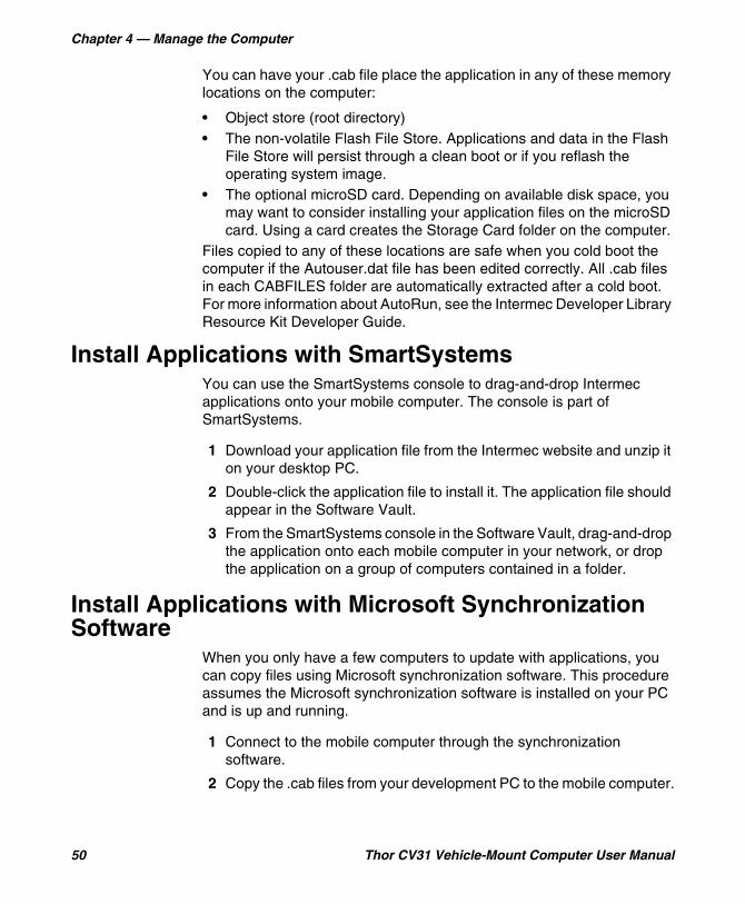
You can have your .cab file place the application in any of these memory locations on the computer:
• Object store (root directory)• The non-volatile Flash File Store. Applications and data in the Flash
File Store will persist through a clean boot or if you reflash the operating system image.
• The optional microSD card. Depending on available disk space, you may want to consider installing your application files on the microSD card. Using a card creates the Storage Card folder on the computer.
Files copied to any of these locations are safe when you cold boot the computer if the Autouser.dat file has been edited correctly. All .cab files in each CABFILES folder are automatically extracted after a cold boot. For more information about AutoRun, see the Intermec Developer Library Resource Kit Developer Guide.
Install Applications with SmartSystemsYou can use the SmartSystems console to drag-and-drop Intermec applications onto your mobile computer. The console is part of SmartSystems.
1 Download your application file from the Intermec website and unzip it on your desktop PC.
2 Double-click the application file to install it. The application file should appear in the Software Vault.
3 From the SmartSystems console in the Software Vault, drag-and-drop the application onto each mobile computer in your network, or drop the application on a group of computers contained in a folder.
Install Applications with Microsoft Synchronization Software
When you only have a few computers to update with applications, you can copy files using Microsoft synchronization software. This procedure assumes the Microsoft synchronization software is installed on your PC and is up and running.
1 Connect to the mobile computer through the synchronization software.
2 Copy the .cab files from your development PC to the mobile computer.
Chapter 4 — Manage the Computer
Thor CV31 Vehicle-Mount Computer User Manual 51
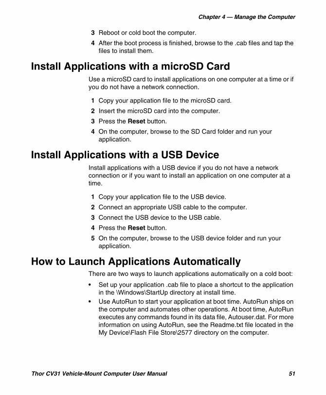
3 Reboot or cold boot the computer.
4 After the boot process is finished, browse to the .cab files and tap the files to install them.
Install Applications with a microSD CardUse a microSD card to install applications on one computer at a time or if you do not have a network connection.
1 Copy your application file to the microSD card.
2 Insert the microSD card into the computer.
3 Press the Reset button.
4 On the computer, browse to the SD Card folder and run your application.
Install Applications with a USB DeviceInstall applications with a USB device if you do not have a network connection or if you want to install an application on one computer at a time.
1 Copy your application file to the USB device.
2 Connect an appropriate USB cable to the computer.
3 Connect the USB device to the USB cable.
4 Press the Reset button.
5 On the computer, browse to the USB device folder and run your application.
How to Launch Applications AutomaticallyThere are two ways to launch applications automatically on a cold boot:
• Set up your application .cab file to place a shortcut to the application in the \Windows\StartUp directory at install time.
• Use AutoRun to start your application at boot time. AutoRun ships on the computer and automates other operations. At boot time, AutoRun executes any commands found in its data file, Autouser.dat. For more information on using AutoRun, see the Readme.txt file located in the My Device\Flash File Store\2577 directory on the computer.
Chapter 4 — Manage the Computer
52 Thor CV31 Vehicle-Mount Computer User Manual
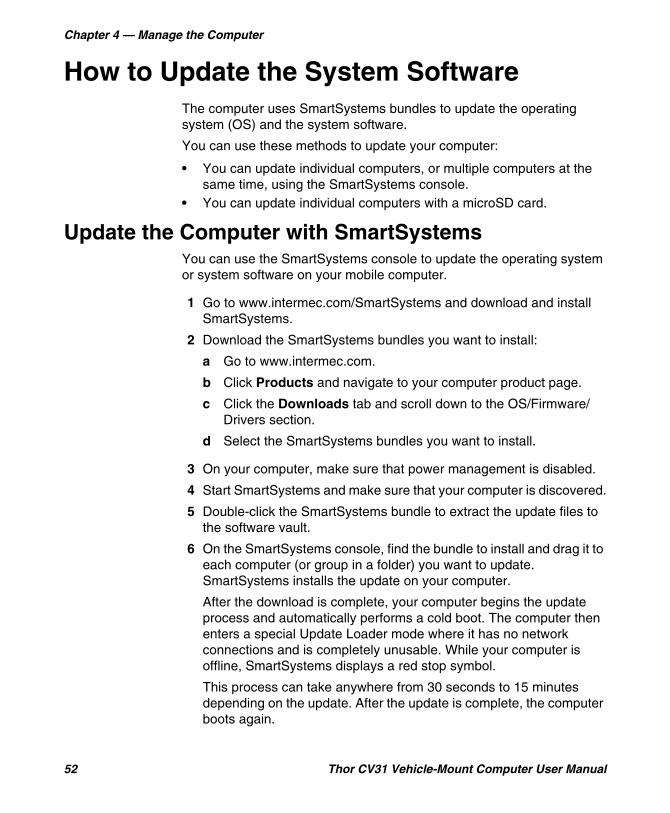
How to Update the System SoftwareThe computer uses SmartSystems bundles to update the operating system (OS) and the system software.
You can use these methods to update your computer:
• You can update individual computers, or multiple computers at the same time, using the SmartSystems console.
• You can update individual computers with a microSD card.
Update the Computer with SmartSystemsYou can use the SmartSystems console to update the operating system or system software on your mobile computer.
1 Go to www.intermec.com/SmartSystems and download and install SmartSystems.
2 Download the SmartSystems bundles you want to install:
a Go to www.intermec.com.
b Click Products and navigate to your computer product page.
c Click the Downloads tab and scroll down to the OS/Firmware/Drivers section.
d Select the SmartSystems bundles you want to install.
3 On your computer, make sure that power management is disabled.
4 Start SmartSystems and make sure that your computer is discovered.
5 Double-click the SmartSystems bundle to extract the update files to the software vault.
6 On the SmartSystems console, find the bundle to install and drag it to each computer (or group in a folder) you want to update. SmartSystems installs the update on your computer.
After the download is complete, your computer begins the update process and automatically performs a cold boot. The computer then enters a special Update Loader mode where it has no network connections and is completely unusable. While your computer is offline, SmartSystems displays a red stop symbol.
This process can take anywhere from 30 seconds to 15 minutes depending on the update. After the update is complete, the computer boots again.
Chapter 4 — Manage the Computer
Thor CV31 Vehicle-Mount Computer User Manual 53
Update the Computer with a microSD CardTo update the computer with a microSD card, you need a microSD adapter card and an SD card reader. You also need to format the microSD card as FAT32.
1 Download the AutoFlash.img file with the updated you want to install:
a Go to www.intermec.com.
b Click Products and navigate to your computer product page.
c Click the Downloads tab and scroll down to the OS/Firmware/Drivers section.
d Select the download you want to install.
2 Insert the microSD card into a microSD adapter card and then place it in the SD card reader connected to your PC.
3 On your PC, navigate to the location of the AutoFlash.img with the update you want to install. Typically, this directory is C:\Program Files\Intermec\SmartSystem\SS_Lib\Software\OS\
4 Copy the AutoFlash.img file to the root directory of the microSD card.
5 Remove the microSD card from the adapter card.
6 Turn off the computer and install the microSD card.
7 Press the Reset button.
8 Turn on the computer.
The update process begins. The computer may restart several times. When the update is complete, the Autoflash Complete message appears.
9 Press the Power button and suspend the computer.
10 Remove the microSD card. If you do not remove the microSD card, the update process repeats each time the computer restarts.
11 Turn on the computer, and follow the setup process.

Chapter 4 — Manage the Computer
54 Thor CV31 Vehicle-Mount Computer User Manual

55
5Troubleshoot and Maintain the Computer
Find solutions to problems you may have while using the computer, as well as information on routine maintenance.
Chapter 5 — Troubleshoot and Maintain the Computer
56 Thor CV31 Vehicle-Mount Computer User Manual
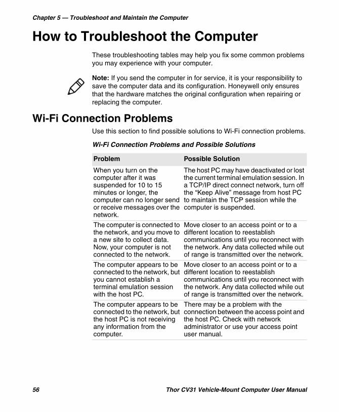
How to Troubleshoot the ComputerThese troubleshooting tables may help you fix some common problems you may experience with your computer.
Wi-Fi Connection ProblemsUse this section to find possible solutions to Wi-Fi connection problems.
Note: If you send the computer in for service, it is your responsibility to save the computer data and its configuration. Honeywell only ensures that the hardware matches the original configuration when repairing or replacing the computer.
Wi-Fi Connection Problems and Possible Solutions
Problem Possible Solution
When you turn on the computer after it was suspended for 10 to 15 minutes or longer, the computer can no longer send or receive messages over the network.
The host PC may have deactivated or lost the current terminal emulation session. In a TCP/IP direct connect network, turn off the “Keep Alive” message from host PC to maintain the TCP session while the computer is suspended.
The computer is connected to the network, and you move to a new site to collect data. Now, your computer is not connected to the network.
Move closer to an access point or to a different location to reestablish communications until you reconnect with the network. Any data collected while out of range is transmitted over the network.
The computer appears to be connected to the network, but you cannot establish a terminal emulation session with the host PC.
Move closer to an access point or to a different location to reestablish communications until you reconnect with the network. Any data collected while out of range is transmitted over the network.
The computer appears to be connected to the network, but the host PC is not receiving any information from the computer.
There may be a problem with the connection between the access point and the host PC. Check with network administrator or use your access point user manual.
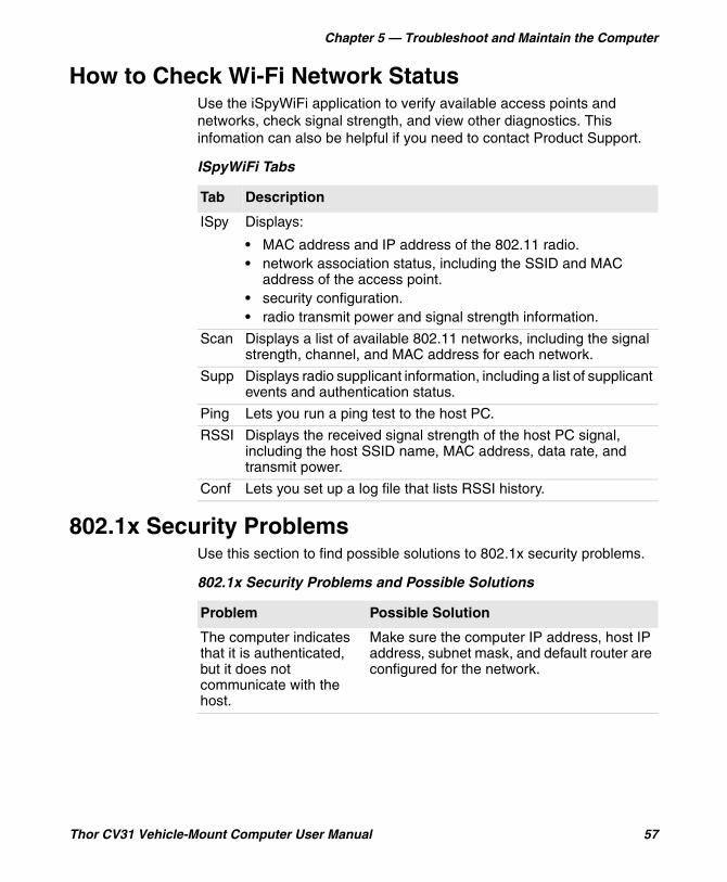
Chapter 5 — Troubleshoot and Maintain the Computer
Thor CV31 Vehicle-Mount Computer User Manual 57
How to Check Wi-Fi Network StatusUse the iSpyWiFi application to verify available access points and networks, check signal strength, and view other diagnostics. This infomation can also be helpful if you need to contact Product Support.
802.1x Security ProblemsUse this section to find possible solutions to 802.1x security problems.
ISpyWiFi Tabs
Tab Description
ISpy Displays:
• MAC address and IP address of the 802.11 radio.• network association status, including the SSID and MAC
address of the access point.• security configuration.• radio transmit power and signal strength information.
Scan Displays a list of available 802.11 networks, including the signal strength, channel, and MAC address for each network.
Supp Displays radio supplicant information, including a list of supplicant events and authentication status.
Ping Lets you run a ping test to the host PC.
RSSI Displays the received signal strength of the host PC signal, including the host SSID name, MAC address, data rate, and transmit power.
Conf Lets you set up a log file that lists RSSI history.
802.1x Security Problems and Possible Solutions
Problem Possible Solution
The computer indicates that it is authenticated, but it does not communicate with the host.
Make sure the computer IP address, host IP address, subnet mask, and default router are configured for the network.
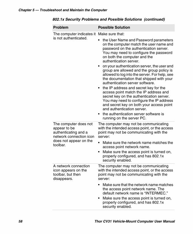
Chapter 5 — Troubleshoot and Maintain the Computer
58 Thor CV31 Vehicle-Mount Computer User Manual
The computer indicates it is not authenticated.
Make sure that:
• the User Name and Password parameters on the computer match the user name and password on the authentication server. You may need to configure the password on both the computer and the authentication server.
• on your authentication server, the user and group are allowed and the group policy is allowed to log into the server. For help, see the documentation that shipped with your authentication server software.
• the IP address and secret key for the access point match the IP address and secret key on the authentication server. You may need to configure the IP address and secret key on both your access point and authentication server.
• the authentication server software is running on the server PC.
The computer does not appear to be authenticating and a network connection icon does not appear on the toolbar.
The computer may not be communicating with the intended access point, or the access point may not be communicating with the server:
• Make sure the network name matches the access point network name.
• Make sure the access point is turned on, properly configured, and has 802.1x security enabled.
A network connection icon appears on the toolbar, but then disappears.
The computer may not be communicating with the intended access point, or the access point may not be communicating with the server:
• Make sure that the network name matches the access point network name. The default network name is “INTERMEC.”
• Make sure the access point is turned on, properly configured, and has 802.1x security enabled.
802.1x Security Problems and Possible Solutions (continued)
Problem Possible Solution
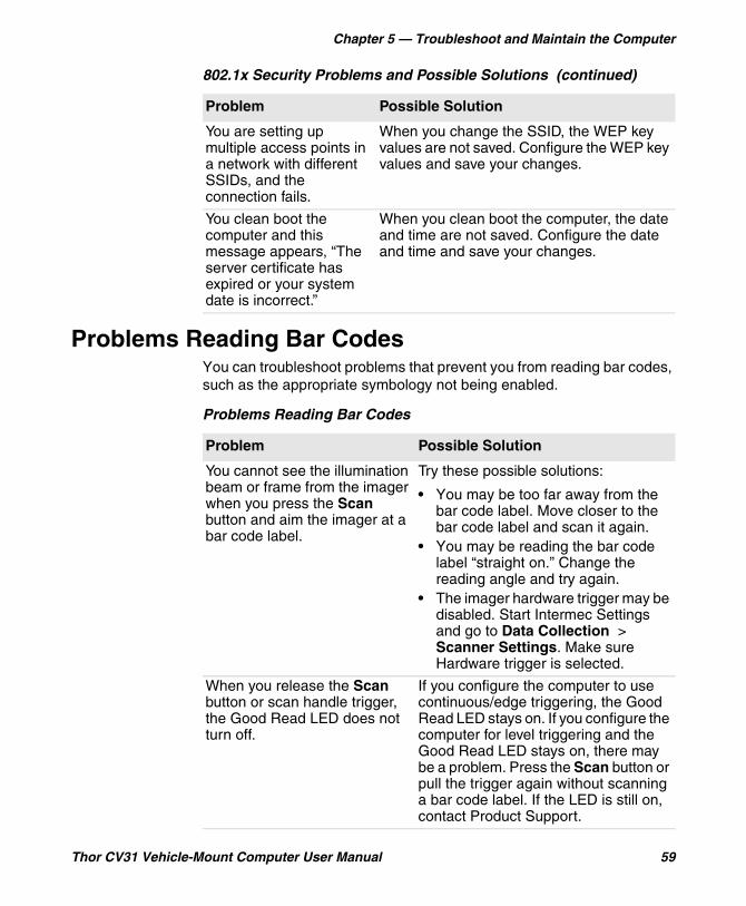
Chapter 5 — Troubleshoot and Maintain the Computer
Thor CV31 Vehicle-Mount Computer User Manual 59
Problems Reading Bar CodesYou can troubleshoot problems that prevent you from reading bar codes, such as the appropriate symbology not being enabled.
You are setting up multiple access points in a network with different SSIDs, and the connection fails.
When you change the SSID, the WEP key values are not saved. Configure the WEP key values and save your changes.
You clean boot the computer and this message appears, “The server certificate has expired or your system date is incorrect.”
When you clean boot the computer, the date and time are not saved. Configure the date and time and save your changes.
802.1x Security Problems and Possible Solutions (continued)
Problem Possible Solution
Problems Reading Bar Codes
Problem Possible Solution
You cannot see the illumination beam or frame from the imager when you press the Scan button and aim the imager at a bar code label.
Try these possible solutions:
• You may be too far away from the bar code label. Move closer to the bar code label and scan it again.
• You may be reading the bar code label “straight on.” Change the reading angle and try again.
• The imager hardware trigger may be disabled. Start Intermec Settings and go to Data Collection > Scanner Settings. Make sure Hardware trigger is selected.
When you release the Scan button or scan handle trigger, the Good Read LED does not turn off.
If you configure the computer to use continuous/edge triggering, the Good Read LED stays on. If you configure the computer for level triggering and the Good Read LED stays on, there may be a problem. Press the Scan button or pull the trigger again without scanning a bar code label. If the LED is still on, contact Product Support.

Chapter 5 — Troubleshoot and Maintain the Computer
60 Thor CV31 Vehicle-Mount Computer User Manual
The scanner or imager cannot read the bar code.
Try these possible solutions:
• Position the scanner beam so that it crosses the entire bar code label in one pass. Try to vary the scanning angle.
• Check the quality of the bar code label. Scan a bar code label that you know scans properly. Compare the quality of the two bar code labels. You may need to replace the label that you cannot scan.
• Make sure the bar code symbology is enabled and configured correctly. Start Intermec Settings and go to Data Collection > Symbologies for the scanning device (scanner, virtual wedge) to check and enable symbologies.
• Make sure the computer application is expecting input from a bar code. You may need to type this information instead.
• The scanner may not be turned on or the scanner may be unable to scan a specific bar code. Run the ScanDiagnostic application.
The scanner or imager cannot read the bar code quickly, or the scanning beam seems to be faint or obscured.
The scanner or imager window may be dirty. Clean the window with a solution of mild soap and water. Wipe dry. Do not allow abrasive material to touch the window.
You read a valid bar code label to enter data for your application. The data decoded by the scan module does not match the data encoded in the bar code label.
The computer may have decoded the bar code label in another symbology. Scan the bar code label again. Make sure you scan the entire label.
The input device attached to the computer does not work well or read bar code labels very quickly.
Set the Scanner Model command to the specific attached input device. Enable only the bar code symbologies being used.
Problems Reading Bar Codes (continued)
Problem Possible Solution

Chapter 5 — Troubleshoot and Maintain the Computer
Thor CV31 Vehicle-Mount Computer User Manual 61
Problems Using the ComputerYou can troubleshoot general problems while using the computer. Before you call Intermec Product Support, look for your problem in the next table, and try the possible solutions.
Problems Using the Computer
Problem Possible Solution
You tap the screen and nothing happens.
Align the screen.
You press the Power button and nothing happens.
• The battery may be completely drained. Replace or charge the battery.
• Restart the computer.
The computer appears to be locked up, and you cannot enter data.
• Press the Power button and select Suspend. Press the Power button again to turn the screen back on.
• Press the Power button and select Reboot.
• Cold boot the computer.• Reload the firmware.
You installed an external antenna, but the computer does not detect it.
Manually enable the antenna:
1 Tap Start > Settings > Control Panel > Intermec Settings.
2 Tap Device Settings > Antenna.3 Under Force external antenna,
select Enabled.
You connected a serial printer to COM1 or COM3, but your application cannot open the COM port.
By default, COM1 and COM3 are enabled for serial scanners. You need to disable the COM port for scanners:
1 Start Intermec Settings. 2 Tap Data Collection > Tethered
Scanners > Tethered Scanner (COM1 or COM3) > Enable scanner port.
3 Clear the Enable scanner port check box.
Chapter 5 — Troubleshoot and Maintain the Computer
62 Thor CV31 Vehicle-Mount Computer User Manual
Call Product SupportIf you are having trouble using your computer and you cannot find a solution in this user manual or from the Knowledge Base (www.hsmknowledgebase.com) or Technical Support Portal (www.hsmsupportportal.com), you can contact Customer Support. For our latest contact information, go to www.honeywellaidc.com/locations.
Before you call Product Support, have this information ready:
• Configuration number (CN) and serial number (SN), available from the Device Health dashboard
• Operating system version• Power management settings• Wireless security settings• SmartSystems Platform Bundle (SSPB) version• Intermec Terminal Emulation (ITE) version and protocol, available
from the ITE main screen.Or, programming language of your custom application and tools used to create it.
Find Your Configuration NumberBefore you call Intermec Product Support, you need know the configuration number of your computer.
1 Press to open the Device Health Dashboard.
2 Double-tap Information. The Hardware Configuration field displays the configuration number.
Find Your Operating System VersionBefore you call Intermec Product Support, you need know the operating system version on your computer.
1 Press to open the Device Health Dashboard.
2 Double-tap Information. The OS Version field displays the operating system version.

Chapter 5 — Troubleshoot and Maintain the Computer
Thor CV31 Vehicle-Mount Computer User Manual 63
How to Restart the ComputerIf the computer or an application locks up, or if the computer does not respond when you press the Power button, you may need to restart the computer.
The computer uses the configuration currently saved in flash memory during the boot process. Try these methods, in order, to restart the computer:
• Reboot: Restarts the computer and goes through the initialization process.
• Reset: Preserves configuration and network settings, but does not necessarily save cached disk data, which may result in data loss.
Reboot the ComputerYou may need to restart the computer to correct conditions where an application stops responding to the system.
• Press the Power button and select Reboot from the menu.
Reset the ComputerIf the computer completely stops responding, you may need to reset the computer. Because resetting may result in data loss, use this method only if all other recovery methods have failed.
• Press the Reset button on the top of the computer. When the reset is complete, the Home screen appears.
Clean the ComputerClean the computer as often as needed. Use one of these recommended cleaning agents: Acetic acid (10% in water), Ethyl alcohol (10% in water), mild soap solutions, or 5% to no more than 10% bleach or sodium hypochlorite with water.
1 Press the Power button to suspend the computer.
2 Dip a clean cloth towel in the cleaning agent and wring out the excess.
3 Wipe the touch screen. Do not allow any abrasive material to touch the surface.
4 Wipe off the exterior of the computer.
5 Wipe dry.

Chapter 5 — Troubleshoot and Maintain the Computer
64 Thor CV31 Vehicle-Mount Computer User Manual

65
ASpecifications

Appendix A — Specifications
66 Thor CV31 Vehicle-Mount Computer User Manual
Physical and Environmental SpecificationsThis section lists the physical and environmental specifications for the CV31.
Physical Dimensions
Specification Measure
Height 17.65 cm (6.95 in)
Width 18.92 cm (7.45 in)
Depth 5.46 cm (2.15 in)
Weight 1.6 kg (3.5 lb)
Power and Electrical Specifications
Specification Measure
Electrical rating 12 VDC ±1.5 V input voltage range
9-36 VDC input voltage range
Backup battery Rechargeable lithium-ion battery
Temperature and Humidity Specifications
Specification Measure
Operating temperature -20 °C to 50 °C (-4 °F to 122 °F)
Operating temperature with optional heater on
-30 °C to 50 °C (-22 °F to 122 °F)
Backup battery charging temperature (battery cell)
0 °C to 40 °C (32 °F to 104 °F)
Storage temperature -20 °C to 50 °C (-4 °F to 122 °F) For maximum battery life, store at 23 °C (73 °F) at 50% charge.
Relative humidity 5% to 95% non-condensing
Appendix A — Specifications
Thor CV31 Vehicle-Mount Computer User Manual 67
Screen Specifications• 163 mm (6.4 in) color VGA• 640 x 480 pixels, supports 16 bpp color depth (65,536 colors)• LCD capable of both portrait and landscape operation• LED backlight• Ambient light sensor
Keyboard Options• Windows DE-15S Backlit QWERTY Keyboard (P/N 340-054-003)• 3270 DE-15S Backlit QWERTY Keyboard (P/N 340-054-001)• VT-220 DE-15S Backlit QWERTY Keyboard (P/N 340-054-004)• 5250 Extreme Temp QWERTY Keyboard (P/N 340-054-102)
Bar Code Symbologies• Australia Post*• Aztec*• BPO (British Post 4-state)*• Canada Post• Codabar• Codablock A• Codablock F• Code 11• Code 39• Code 93• Code 128/GS1-128• DataMatrix*• Dutch Post*• EAN/UPC• GS1 Composite*• GS1 DataBar Expanded• GS1 DataBar Limited• GS1 DataBar Omni-Directional• HanXin• Infomail• Intelligent Mail• Interleaved 2 of 5
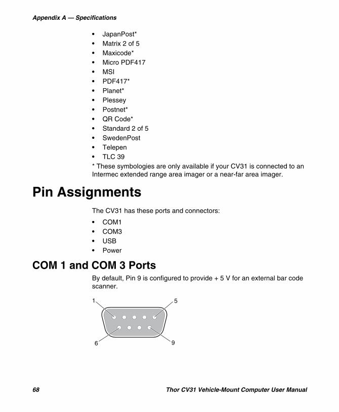
Appendix A — Specifications
68 Thor CV31 Vehicle-Mount Computer User Manual
• JapanPost*• Matrix 2 of 5• Maxicode*• Micro PDF417• MSI• PDF417*• Planet*• Plessey• Postnet*• QR Code*• Standard 2 of 5• SwedenPost• Telepen• TLC 39* These symbologies are only available if your CV31 is connected to an Intermec extended range area imager or a near-far area imager.
Pin AssignmentsThe CV31 has these ports and connectors:
• COM1• COM3• USB• Power
COM 1 and COM 3 PortsBy default, Pin 9 is configured to provide + 5 V for an external bar code scanner.
5
96
1
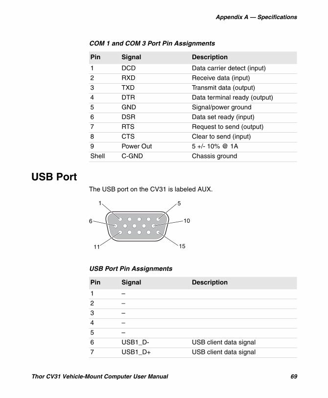
Appendix A — Specifications
Thor CV31 Vehicle-Mount Computer User Manual 69
USB PortThe USB port on the CV31 is labeled AUX.
COM 1 and COM 3 Port Pin Assignments
Pin Signal Description
1 DCD Data carrier detect (input)
2 RXD Receive data (input)
3 TXD Transmit data (output)
4 DTR Data terminal ready (output)
5 GND Signal/power ground
6 DSR Data set ready (input)
7 RTS Request to send (output)
8 CTS Clear to send (input)
9 Power Out 5 +/- 10% @ 1A
Shell C-GND Chassis ground
USB Port Pin Assignments
Pin Signal Description
1 –
2 –
3 –
4 –
5 –
6 USB1_D- USB client data signal
7 USB1_D+ USB client data signal
1
11
10
5
15
6
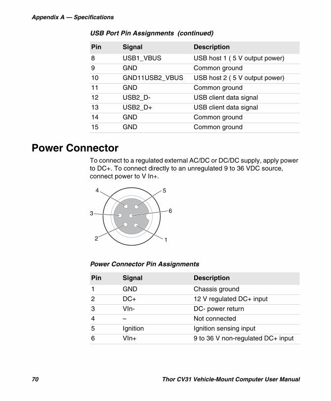
Appendix A — Specifications
70 Thor CV31 Vehicle-Mount Computer User Manual
Power ConnectorTo connect to a regulated external AC/DC or DC/DC supply, apply power to DC+. To connect directly to an unregulated 9 to 36 VDC source, connect power to V In+.
8 USB1_VBUS USB host 1 ( 5 V output power)
9 GND Common ground
10 GND11USB2_VBUS USB host 2 ( 5 V output power)
11 GND Common ground
12 USB2_D- USB client data signal
13 USB2_D+ USB client data signal
14 GND Common ground
15 GND Common ground
USB Port Pin Assignments (continued)
Pin Signal Description
Power Connector Pin Assignments
Pin Signal Description
1 GND Chassis ground
2 DC+ 12 V regulated DC+ input
3 VIn- DC- power return
4 – Not connected
5 Ignition Ignition sensing input
6 VIn+ 9 to 36 V non-regulated DC+ input
12
3
4 5
6
71
BDevice Settings
This section lists all default settings for computer-specific features such as the backlight and power management.
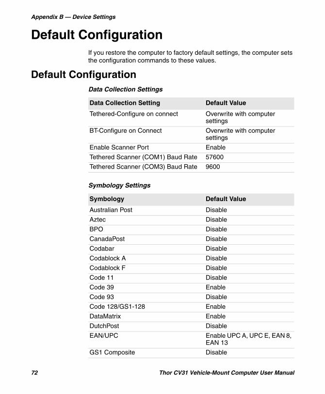
Appendix B — Device Settings
72 Thor CV31 Vehicle-Mount Computer User Manual
Default ConfigurationIf you restore the computer to factory default settings, the computer sets the configuration commands to these values.
Default ConfigurationData Collection Settings
Data Collection Setting Default Value
Tethered-Configure on connect Overwrite with computer settings
BT-Configure on Connect Overwrite with computer settings
Enable Scanner Port Enable
Tethered Scanner (COM1) Baud Rate 57600
Tethered Scanner (COM3) Baud Rate 9600
Symbology Settings
Symbology Default Value
Australian Post Disable
Aztec Disable
BPO Disable
CanadaPost Disable
Codabar Disable
Codablock A Disable
Codablock F Disable
Code 11 Disable
Code 39 Enable
Code 93 Disable
Code 128/GS1-128 Enable
DataMatrix Enable
DutchPost Disable
EAN/UPC Enable UPC A, UPC E, EAN 8, EAN 13
GS1 Composite Disable
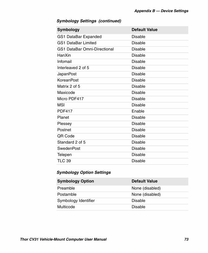
Appendix B — Device Settings
Thor CV31 Vehicle-Mount Computer User Manual 73
GS1 DataBar Expanded Disable
GS1 DataBar Limited Disable
GS1 DataBar Omni-Directional Disable
HanXin Disable
Infomail Disable
Interleaved 2 of 5 Disable
JapanPost Disable
KoreanPost Disable
Matrix 2 of 5 Disable
Maxicode Disable
Micro PDF417 Disable
MSI Disable
PDF417 Enable
Planet Disable
Plessey Disable
Postnet Disable
QR Code Disable
Standard 2 of 5 Disable
SwedenPost Disable
Telepen Disable
TLC 39 Disable
Symbology Option Settings
Symbology Option Default Value
Preamble None (disabled)
Postamble None (disabled)
Symbology Identifier Disable
Multicode Disable
Symbology Settings (continued)
Symbology Default Value
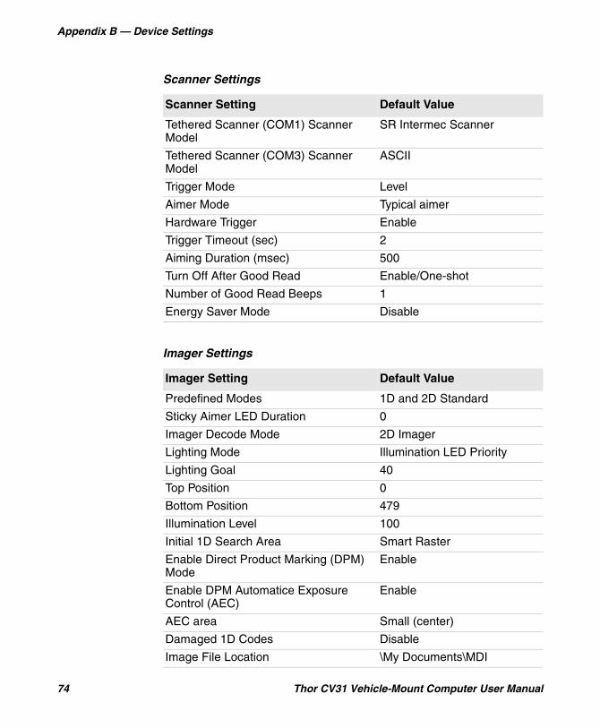
Appendix B — Device Settings
74 Thor CV31 Vehicle-Mount Computer User Manual
Scanner Settings
Scanner Setting Default Value
Tethered Scanner (COM1) Scanner Model
SR Intermec Scanner
Tethered Scanner (COM3) Scanner Model
ASCII
Trigger Mode Level
Aimer Mode Typical aimer
Hardware Trigger Enable
Trigger Timeout (sec) 2
Aiming Duration (msec) 500
Turn Off After Good Read Enable/One-shot
Number of Good Read Beeps 1
Energy Saver Mode Disable
Imager Settings
Imager Setting Default Value
Predefined Modes 1D and 2D Standard
Sticky Aimer LED Duration 0
Imager Decode Mode 2D Imager
Lighting Mode Illumination LED Priority
Lighting Goal 40
Top Position 0
Bottom Position 479
Illumination Level 100
Initial 1D Search Area Smart Raster
Enable Direct Product Marking (DPM) Mode
Enable
Enable DPM Automatice Exposure Control (AEC)
Enable
AEC area Small (center)
Damaged 1D Codes Disable
Image File Location \My Documents\MDI
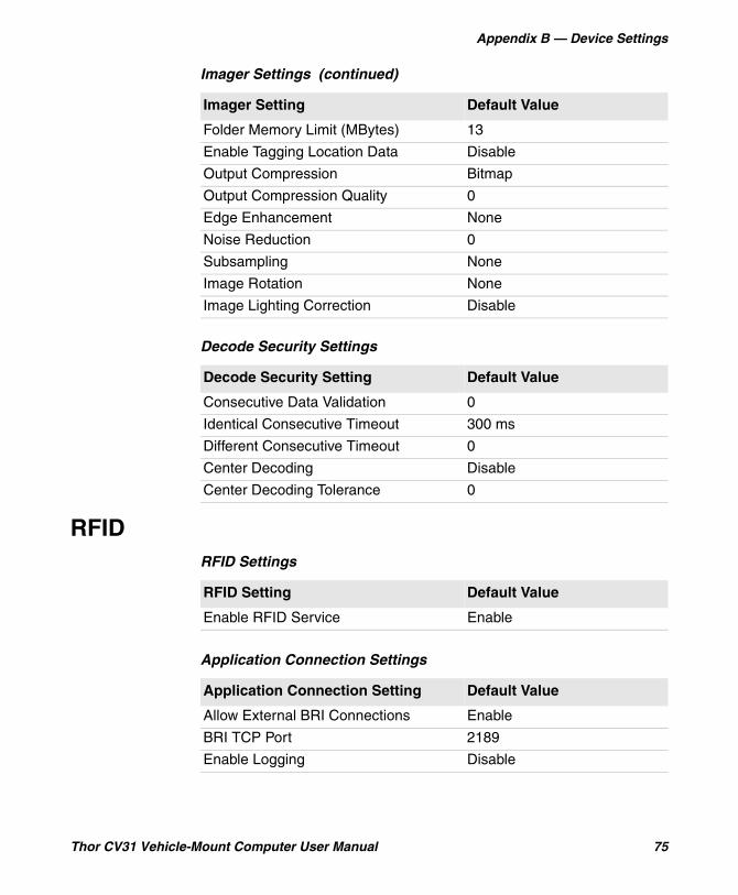
Appendix B — Device Settings
Thor CV31 Vehicle-Mount Computer User Manual 75
RFID
Folder Memory Limit (MBytes) 13
Enable Tagging Location Data Disable
Output Compression Bitmap
Output Compression Quality 0
Edge Enhancement None
Noise Reduction 0
Subsampling None
Image Rotation None
Image Lighting Correction Disable
Decode Security Settings
Decode Security Setting Default Value
Consecutive Data Validation 0
Identical Consecutive Timeout 300 ms
Different Consecutive Timeout 0
Center Decoding Disable
Center Decoding Tolerance 0
Imager Settings (continued)
Imager Setting Default Value
RFID Settings
RFID Setting Default Value
Enable RFID Service Enable
Application Connection Settings
Application Connection Setting Default Value
Allow External BRI Connections Enable
BRI TCP Port 2189
Enable Logging Disable
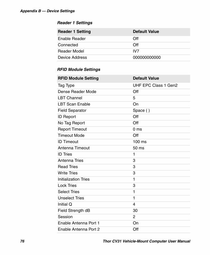
Appendix B — Device Settings
76 Thor CV31 Vehicle-Mount Computer User Manual
Reader 1 Settings
Reader 1 Setting Default Value
Enable Reader Off
Connected Off
Reader Model IV7
Device Address 000000000000
RFID Module Settings
RFID Module Setting Default Value
Tag Type UHF EPC Class 1 Gen2
Dense Reader Mode Off
LBT Channel 5
LBT Scan Enable On
Field Separator Space ( )
ID Report Off
No Tag Report Off
Report Timeout 0 ms
Timeout Mode Off
ID Timeout 100 ms
Antenna Timeout 50 ms
ID Tries 1
Antenna Tries 3
Read Tries 3
Write Tries 3
Initialization Tries 1
Lock Tries 3
Select Tries 1
Unselect Tries 1
Initial Q 4
Field Strength dB 30
Session 2
Enable Antenna Port 1 On
Enable Antenna Port 2 Off
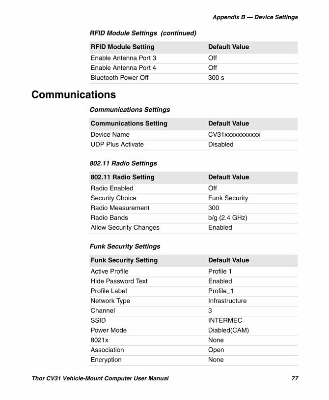
Appendix B — Device Settings
Thor CV31 Vehicle-Mount Computer User Manual 77
Communications
Enable Antenna Port 3 Off
Enable Antenna Port 4 Off
Bluetooth Power Off 300 s
RFID Module Settings (continued)
RFID Module Setting Default Value
Communications Settings
Communications Setting Default Value
Device Name CV31xxxxxxxxxxx
UDP Plus Activate Disabled
802.11 Radio Settings
802.11 Radio Setting Default Value
Radio Enabled Off
Security Choice Funk Security
Radio Measurement 300
Radio Bands b/g (2.4 GHz)
Allow Security Changes Enabled
Funk Security Settings
Funk Security Setting Default Value
Active Profile Profile 1
Hide Password Text Enabled
Profile Label Profile_1
Network Type Infrastructure
Channel 3
SSID INTERMEC
Power Mode Diabled(CAM)
8021x None
Association Open
Encryption None
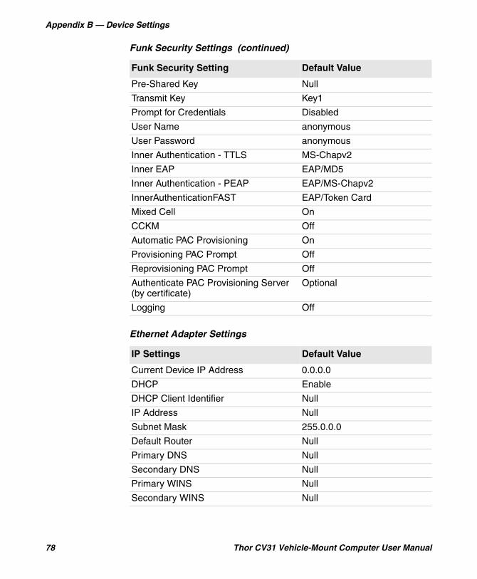
Appendix B — Device Settings
78 Thor CV31 Vehicle-Mount Computer User Manual
Pre-Shared Key Null
Transmit Key Key1
Prompt for Credentials Disabled
User Name anonymous
User Password anonymous
Inner Authentication - TTLS MS-Chapv2
Inner EAP EAP/MD5
Inner Authentication - PEAP EAP/MS-Chapv2
InnerAuthenticationFAST EAP/Token Card
Mixed Cell On
CCKM Off
Automatic PAC Provisioning On
Provisioning PAC Prompt Off
Reprovisioning PAC Prompt Off
Authenticate PAC Provisioning Server (by certificate)
Optional
Logging Off
Ethernet Adapter Settings
IP Settings Default Value
Current Device IP Address 0.0.0.0
DHCP Enable
DHCP Client Identifier Null
IP Address Null
Subnet Mask 255.0.0.0
Default Router Null
Primary DNS Null
Secondary DNS Null
Primary WINS Null
Secondary WINS Null
Funk Security Settings (continued)
Funk Security Setting Default Value
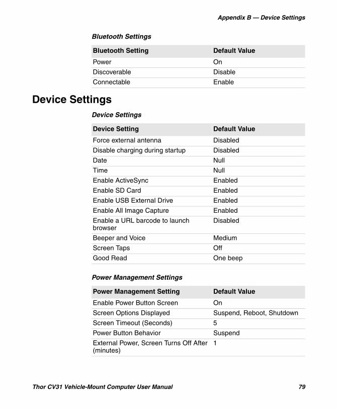
Appendix B — Device Settings
Thor CV31 Vehicle-Mount Computer User Manual 79
Device Settings
Bluetooth Settings
Bluetooth Setting Default Value
Power On
Discoverable Disable
Connectable Enable
Device Settings
Device Setting Default Value
Force external antenna Disabled
Disable charging during startup Disabled
Date Null
Time Null
Enable ActiveSync Enabled
Enable SD Card Enabled
Enable USB External Drive Enabled
Enable All Image Capture Enabled
Enable a URL barcode to launch browser
Disabled
Beeper and Voice Medium
Screen Taps Off
Good Read One beep
Power Management Settings
Power Management Setting Default Value
Enable Power Button Screen On
Screen Options Displayed Suspend, Reboot, Shutdown
Screen Timeout (Seconds) 5
Power Button Behavior Suspend
External Power, Screen Turns Off After (minutes)
1
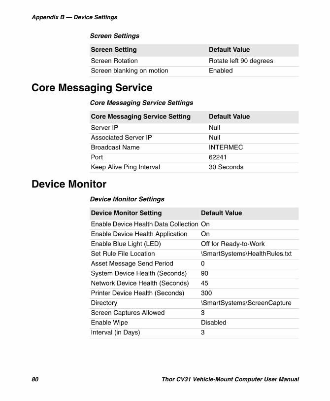
Appendix B — Device Settings
80 Thor CV31 Vehicle-Mount Computer User Manual
Core Messaging Service
Device Monitor
Screen Settings
Screen Setting Default Value
Screen Rotation Rotate left 90 degrees
Screen blanking on motion Enabled
Core Messaging Service Settings
Core Messaging Service Setting Default Value
Server IP Null
Associated Server IP Null
Broadcast Name INTERMEC
Port 62241
Keep Alive Ping Interval 30 Seconds
Device Monitor Settings
Device Monitor Setting Default Value
Enable Device Health Data Collection On
Enable Device Health Application On
Enable Blue Light (LED) Off for Ready-to-Work
Set Rule File Location \SmartSystems\HealthRules.txt
Asset Message Send Period 0
System Device Health (Seconds) 90
Network Device Health (Seconds) 45
Printer Device Health (Seconds) 300
Directory \SmartSystems\ScreenCapture
Screen Captures Allowed 3
Enable Wipe Disabled
Interval (in Days) 3
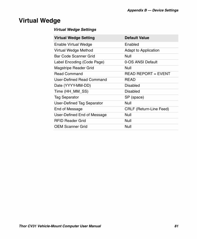
Appendix B — Device Settings
Thor CV31 Vehicle-Mount Computer User Manual 81
Virtual WedgeVirtual Wedge Settings
Virtual Wedge Setting Default Value
Enable Virtual Wedge Enabled
Virtual Wedge Method Adapt to Application
Bar Code Scanner Grid Null
Label Encoding (Code Page) 0-OS ANSI Default
Magstripe Reader Grid Null
Read Command READ REPORT = EVENT
User-Defined Read Command READ
Date (YYYY-MM-DD) Disabled
Time (HH_MM_SS) Disabled
Tag Separator SP (space)
User-Defined Tag Separator Null
End of Message CRLF (Return-Line Feed)
User-Defined End of Message Null
RFID Reader Grid Null
OEM Scanner Grid Null

Honeywell Scanning & Mobility9680 Old Bailes RoadFort Mill, SC 29707www.honeywellaidc.com
Thor CV31 Vehicle-Mount Computer User Manual
*935-081-001*P/N 935-081-001
Related Documents