This PowerPoint shows circuit diagrams superimposed on the membrane in order to illustrate current flow in three of the tutorials: •The Membrane Tutorial (diagrams of current flow that accompany the steps of the tutorial) •The Unmyelinated Axon Tutorial •The Myelinated Axon Tutorial Ann E. Stuart

This PowerPoint shows circuit diagrams superimposed on the membrane in order to illustrate current flow in three of the tutorials: The Membrane Tutorial.
Dec 16, 2015
Welcome message from author
This document is posted to help you gain knowledge. Please leave a comment to let me know what you think about it! Share it to your friends and learn new things together.
Transcript

This PowerPoint shows circuit diagrams superimposed on the membrane in order to illustrate current flow in three of the tutorials:
•The Membrane Tutorial (diagrams of current flow that accompany the steps of the tutorial)•The Unmyelinated Axon Tutorial•The Myelinated Axon Tutorial
Ann E. Stuart

stimulating electrode inserted
Patch Membrane Tutorial
outside
inside c
Vm = 0 mV
Vm
Current may be injected through a microelectrode.
Patch Membrane Tutorial
outside
inside c
Vm = 0 mV
VmAch-gated channels
Current may also be injected by the opening of a channel.

+++++++
- - - - - - -
electrode injects positive charge(20nA current pulse)
Vm = 200 mV at end of current pulse
Patch Membrane Tutorial steps 1 & 2
Vm
injected current pulse
Vm

+++++++
- - - - - - -
electrode injects positive charge(20nA current pulse)
Vm = 200 mV at end of current pulse
Patch Membrane Tutorial steps 1 & 2
Vm
injected current pulse
Vm

+++++++
Patch Membrane Tutorial steps 1 & 2
-----------
Vm = 200 mV at end of pulse
Vm
Q = CV
dV/dT = 1/C [dQ/dt];V = 1/C [Q]
Icap = C [dV/dt]dV/dT = 1/C [Icap]
dQ/dt = Icap
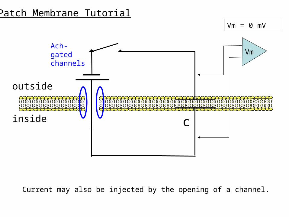
Patch Membrane Tutorial step 3: add leak channel
rleakc
Vm
1 2
Vm
t

Time constant
Vm
Vm
tau = Rm Cm
tau = the time it takes for voltage to rise to 67% (1-1/e) or fall to 33% (1/e) of its final value
t
tautau
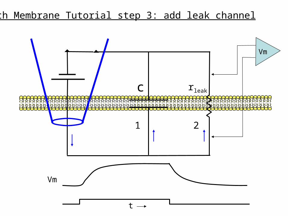
Patch Membrane Tutorial step 4: add HH Na & K channels
Vm
Na channels (fast)
K channels (slow)
Depolarizing (positive) current is injected.
The current first flows out through the capacitance C.
As the voltage builds up across C, current flows out through leak channels.
Na channels open, allowing the Na battery to drive positive current inward through these channels (outward Icap).
K channels then open, allowing the K battery to drive positive current out through these channels (inward Icap).

Passive Axon Tutorial: add longitudinal resistances
ro
ri
ro
ri
rm rm ( = rleak)
(usually negligible)

L = √ rm / ri
distance x
L
• L = the distance over which a voltage step decays to 1/e (33%) of its original value.
• If rm is large compared to ri, current will flow down the inside of the axon and L will be large.
• L tracks the (square root of the) rm/ri ratio:
Length constant (L)
mV

Unmyelinated Axon Tutorial: add HH Na & K channels
the AP

Myelinated Axon Tutorial: add myelin
the AP
tau = RmCm Cm decreases because of many capactors in seriesRm increases because of equivalent # of resistors in seriestau does not change
L = √ rm/ri rm becomes very much largerL becomes very much longer
time constant:
length constant:
Related Documents