1 This is to certify that the dissertation work done by _________ in partial fulfillment of the requirement for the award of the Engineering Training in ___________ P.T.P.S, (H.P.G.C.L), Panipat has carried out ___weeks training under our supervision and guidance. Name : Roll no. : Division : Date of commencement : Date of completion : Mr. _______________ has worked under my supervision during above training period. I have read this report. It meets our expectation and accurately reflects work done by him. ( ) ( ) Executive Engineer Assistant Executive Engineer

Welcome message from author
This document is posted to help you gain knowledge. Please leave a comment to let me know what you think about it! Share it to your friends and learn new things together.
Transcript

1
This is to certify that the dissertation work done by _________ in partial
fulfillment of the requirement for the award of the Engineering Training in
___________ P.T.P.S, (H.P.G.C.L), Panipat has carried out ___weeks
training under our supervision and guidance.
Name :
Roll no. :
Division :
Date of commencement :
Date of completion :
Mr. _______________ has worked under my supervision during above
training period. I have read this report. It meets our expectation and
accurately reflects work done by him.
( ) ( )
Executive Engineer Assistant Executive Engineer
2
ACKNOWLEDGEMENT
The present report would not have been possible with out
the help, I have received from various quarters. I shall be
failing in my duty if don’t acknowledge the help and
guidance from these sources.
I extend my special thanks to Er. Himanshu Gupta XEN
Training division and Er._________________ for their
benevolent guidance and kind cooperation through out my
training and for completing this project report. I also
convey my special thanks to staff members. This guidance
has helped me a lot in power plant familiarizations and
understanding various plant processes.
Last but not least, I am thankful to all for their sincere
effort during placement.
3
INDEX
S.NO. Contents
1. Acknowledgement
2. Introduction/Functional of P.T.P.S
3. Familiarization with plant
4. Steam Turbine Specification
5. Valves
6. Rotor Coupling and Bearings
6. Turbine Oil System
7. Condenser
9. Electrostatic Precipitator
10 ID FANS, FD FANS, PA FANS
11. Generator Transformer Specification
12. Station Transformer Specification
13 Unit Auxiliary Transformer Specification
4
INTRODUCTION
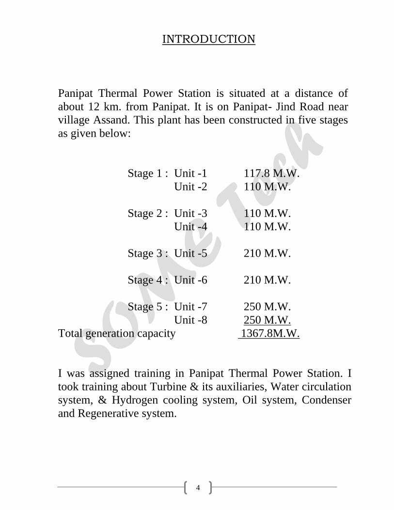
Panipat Thermal Power Station is situated at a distance of
about 12 km. from Panipat. It is on Panipat- Jind Road near
village Assand. This plant has been constructed in five stages
as given below:
Stage 1 : Unit -1 117.8 M.W.
Unit -2 110 M.W.
Stage 2 : Unit -3 110 M.W.
Unit -4 110 M.W.
Stage 3 : Unit -5 210 M.W.
Stage 4 : Unit -6 210 M.W.
Stage 5 : Unit -7 250 M.W.
Unit -8 250 M.W.
Total generation capacity 1367.8M.W.
I was assigned training in Panipat Thermal Power Station. I
took training about Turbine & its auxiliaries, Water circulation
system, & Hydrogen cooling system, Oil system, Condenser
and Regenerative system.

5
FUNCTIONAL DESCRIPTION
The Thermal Power Station burns fuel & uses the resultant
to make the steam, which derives the turbo generator. The
Fuel i.e. coal is burnt in pulverized from. The pressure
energy of the steam produce is converted into mechanical
energy with the help of turbine. The mechanical energy is
fed to the generator where the magnet rotate inside a set of
stator winding & thus electricity is produced in India 65%
of total power is generated by thermal power stations. To
understand the working of the Thermal Power Station
plant, we can divide the whole process into following parts.
Steam
Water
Air
Fuel
Feed pump 2 Feed pump 1
Feed water
heater
Generator
Boiler
Low
Pressure
Turbine
High
Pressure
Turbine
Condenser
6
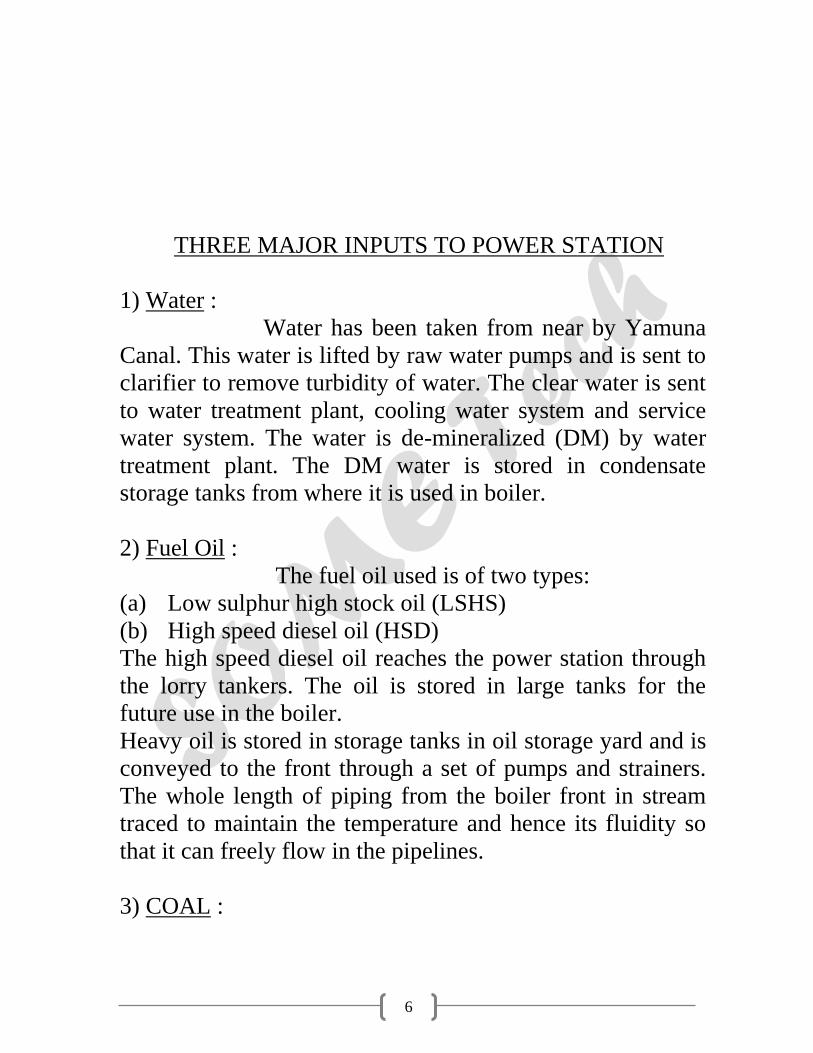
THREE MAJOR INPUTS TO POWER STATION
1) Water :
Water has been taken from near by Yamuna
Canal. This water is lifted by raw water pumps and is sent to
clarifier to remove turbidity of water. The clear water is sent
to water treatment plant, cooling water system and service
water system. The water is de-mineralized (DM) by water
treatment plant. The DM water is stored in condensate
storage tanks from where it is used in boiler.
2) Fuel Oil :
The fuel oil used is of two types:
(a) Low sulphur high stock oil (LSHS)
(b) High speed diesel oil (HSD)
The high speed diesel oil reaches the power station through
the lorry tankers. The oil is stored in large tanks for the
future use in the boiler.
Heavy oil is stored in storage tanks in oil storage yard and is
conveyed to the front through a set of pumps and strainers.
The whole length of piping from the boiler front in stream
traced to maintain the temperature and hence its fluidity so
that it can freely flow in the pipelines.
3) COAL :
7
The coal reaches the plant in the railways
wagons. The unloading of coal is done mechanically by
tilting the wagons by tippler. The coal is sent to the coal
storage yard through the conveyor belts. The crushed coal
from store is sent to the mill bunkers through conveyor belts.
The air which takes away the coal dust
passes upward into the classifier where the direction of flow
is changed abruptly. This causes the coarse particle in the air
coal stream to finer coal dust along with the primary air
leaves the classifier onto the coal transport piping from
where it goes to nozzle. Pulverized coal obtained from coal
mill can not be burnt directly.

8
FAMILARIZATION WITH PLANT
BOILER:
Boiler is a device used for producing steam. There
are two types of boilers:
a) Fire tube boiler
b) Water tube boiler
Here, boiler used is of water tube type. In the boiler, heat
energy transfer takes place through tube walls and drum.
The gases lose their heat to water in the boiler or
superheated. The escape heat is used to heat the water
through economizer.
ID and FD fans are used to produce artificial draught. The
fuel oil is used to ignite the boiler and pulverized coal is
lifted from the coal mills by PA fans.
TURBINE & GENERATOR( TG):
Turbine is form of heat engine in which available
heat energy in the form of steam is converted into kinetic
energy to rotate the turbine by steam expansion in suitable
shaped nozzles In Thermal Power Station there are reaction
turbines.
The turbine consists of three stages: high pressure,
intermediate pressure and low pressure. Steam enters the
turbine at 350oC with maximum allowable temp. of 545oC.
Cold reheat steam goes to boiler, reheated at 540oC, then fed
to medium pressure parts of the turbine. Then, after cooling
it goes to hot well.
9
The shaft is coupled with generator. The generator
converts the kinetic energy of the rotating shaft to electric
energy. Field windings are excited by D.C. power using
exciter. Shaft of generator rotates at 3000 rpm speed.
CONDENSER:
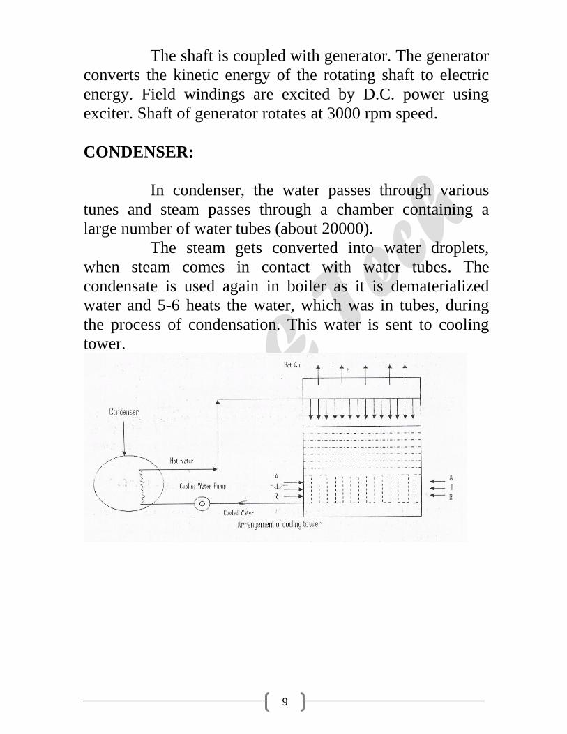
In condenser, the water passes through various
tunes and steam passes through a chamber containing a
large number of water tubes (about 20000).
The steam gets converted into water droplets,
when steam comes in contact with water tubes. The
condensate is used again in boiler as it is dematerialized
water and 5-6 heats the water, which was in tubes, during
the process of condensation. This water is sent to cooling
tower.
10
COOLING TOWER:
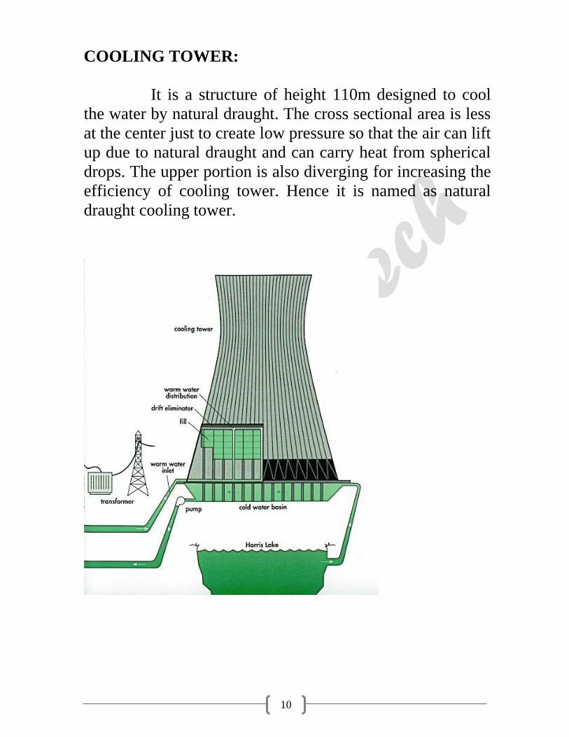
It is a structure of height 110m designed to cool
the water by natural draught. The cross sectional area is less
at the center just to create low pressure so that the air can lift
up due to natural draught and can carry heat from spherical
drops. The upper portion is also diverging for increasing the
efficiency of cooling tower. Hence it is named as natural
draught cooling tower.

11
ELECTROSTATIC PRECIPITATIOR:
It is an electronic device, which removes the ash
particles from the smoke through furnace of boiler. It helps
in prevention of air pollution. It works on the principle that
a charged particle is attracted towards opposite charge.
When the fly ash comes between the opposites charged
plated it gets charged and is attracted towards the plates and
then collected from the plates by the discharging particles.
ASH HANDLING PLANT:
Ash is not discharged as such to pollute the land,
air and water, but slurry of ash is made in ash handling plant
and this slurry is dumped in the wasteland, kept for the
purpose.
SWITCH YARD:
Switchyard is the area, which feed the grid supply
to the station transformer and fees the grid by the power
generator by the unit. The power supply control is
administrated here and the units consumed and supplies are
recorded in the control room. The connections of 220KV
BUS to the station transformer is done by using the isolated
and gas filled circuit breakers.
ELECTRICITY FROM COAL:
Electric power generation takes place in the
following steps:

12
1. Coal to steam
2. Steam to mechanical power
3. Switching and transmission
COAL TO STEAM:
The boiler burns pulverized coal at rates up
to 200 tons per hour. From the coal store, fuel is carried on a
conveyor belt and discharged by means of a coal tipper into
the bunker. It then falls through a weighed into the coal-
pulverizing mill where it is ground to a powder as fine as
flour. Air is drawn from the top of the boiler house by the
forced draught fan and passed through the air preheaters to
the hot air duct. From here some of the air passes directly to
the burners and the remainder is taken through the primary
air fan to the pulverizing mill, where it is mixed with the
powdered coal, blowing it along pipes to the burners of the
furnace. Here it mixes with the rest of the air and burns with
great heat.
The boiler consists of a large number of tubes and
the heat produced raises the temp. of the water circulating in
them to create steam, which passes to the steam drum at
very high pressure. The steam is then heated further in the
super heater and fed through outlet valve to the high pr.
cylinder of the steam turbine.

13
When the steam has been through the first
cylinder (high pr.) of the turbine, it is returned to the
repeater of the boiler and reheated before being passed
through the other cylinders(intermediate and low pr.) of the
turbine.From the turbine the steam passes into a condenser
to be turned back into water ‘condensate’. This is pumped
through feed heaters where it may be heated to about 250oC
to the economizer where the temp. is raised sufficiently for
the condensate to be returned to the lower half of the steam
drum of the boiler.
The flue gases leaving the boiler are used to reheat
the condensate in the economizer and then pass through the
air pre-heaters to the electro-static precipitator. Finally they
are drawn by the induced draught fan into the main flue and
to the chimney.
STEAM TO MECHANICAL POWER:
From the boiler, a steam pipe conveys
steam to the turbine through a stop valve and through
control valves that automatically regulate the supply of
steam of the turbine, Stop valve and control valves are
located in a steam chest and a governor, driven from the
main turbine shaft, operates the control valves to regulate
the amount of steam used.

14
Steam from the control valves enters the high pr.
cylinder of the turbine, where it passes through a ring of
stationary blades fixed to the cylinder wall. These act as
nozzles and direct the steam mounted on a disc secured to
the turbine shaft. This second ring turns the shaft as a result
of the force of the steam. The stationary and moving blades
together constitute a ‘stage’ of the turbine and in practice
many stages are necessary. The steam passes through each
stage in turn until it reaches the end of the high pr. cylinder
and in its passage some of its heat energy is charged into
mechanical energy.
The steam leaving the high pr. cylinder goes back
to the boiler for reheating and is returned to the intermediate
pr. cylinder. Here it passes through another series of
stationary and moving blades.
Finally, the steam is taken to
the low pr. cylinder each of which it enters at the center
flowing outwards in opposite directions through the rows of
turbine blades- an arrangement known as double flow-to the
extremities of the cylinder. As the steam gives up its heat
energy to drive the turbine, its temp. falls and it expands.
The turbine shaft rotates at 3000 rpm at 50 Hz. The turbine
shaft drives the generator to generate alternating current.
When as much energy as possible has been
extracted from the steam it is exhausted directly to the
condenser. This runs the length of the low pr. part of the
turbine and may be beneath or on either side of it. From the
condenser, the condensate is pumped through low pr. feed
15
heaters by the extraction pump, after which its pr. is raised
to boiler pr. by the boiler feed pump. It passed through
further feed heaters to the economizer and the boiler for
recon version into steam.
SWITCHING AND TRANSMISSION:
The electricity is usually produced in
the stator windings of the large modern generators at about
25,000 volts and is fed through terminal connections to one
side of a generator transformer that steps up the voltage
132000, 220000 or 400000 volts. From here conductors
carry it to a series of three switches comprising an isolator, a
circuit breaker and another isolator.
The circuit breaker, which is a heavy-duty switch
capable of operating in a fraction of a second, is used to
switch off the current flowing to the transmission lines.
Once the current has been interrupted the isolators can be
opened. These isolate the circuit breaker from all outside
electrical sources.
From the circuit breaker the current is taken to the
bus bars-conductors, which run the length of the switching
compound and then to another circuit breaker with its
associated isolates before feeding to the grid.
Three wires are used in a ‘three-phase’ system for
large power transmission. The center of the power station is
the control room. Here engineers monitor the output of

16
electricity, supervising and controlling the operation of the
generating plant and high voltage switch gear and directing
power to the grid system as required.
17
STEAM TURBINE
Steam Turbines
The steam turbine is a prime mover that converts the stored
mechanical energy in steam into rotational mechanical
energy. A turbine pair consists of a ring of fixed blade and
a ring of moving blades. The blades are so designed that the
steam glides overt eh blade surface without striking it. As
the steam floes over the covered surface of blade, it exerts a
pressure on the blade along its whole length owing to its
centrifugal force. The motive force on the blade will be the
resultant of the centrifugal pressures on the blade length
plus the effect of change of the steam as it flows over the
blade.
Specification:
Type 3 Cylinder Mixed Flow Tandem
Coupled.
Make BHEL.
Capacity 250MW
Speed 3000 rpm
Stages Nos.(HP, IP, LP)
Inlet Steam Pressure 150 Kg/cm2.
Inlet Steam Temperature 535oC.
Overall Length 16.975m.
Overall Width 10.5m.
General Design Features
18
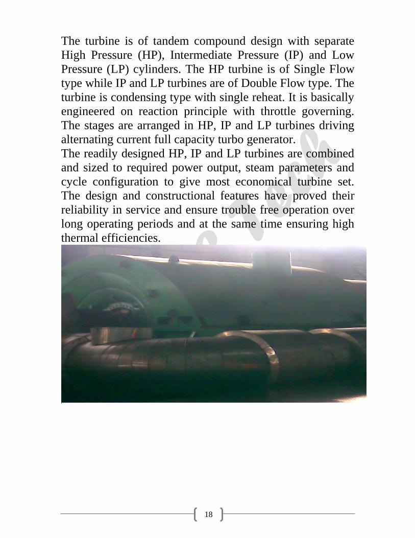
The turbine is of tandem compound design with separate
High Pressure (HP), Intermediate Pressure (IP) and Low
Pressure (LP) cylinders. The HP turbine is of Single Flow
type while IP and LP turbines are of Double Flow type. The
turbine is condensing type with single reheat. It is basically
engineered on reaction principle with throttle governing.
The stages are arranged in HP, IP and LP turbines driving
alternating current full capacity turbo generator.
The readily designed HP, IP and LP turbines are combined
and sized to required power output, steam parameters and
cycle configuration to give most economical turbine set.
The design and constructional features have proved their
reliability in service and ensure trouble free operation over
long operating periods and at the same time ensuring high
thermal efficiencies.

19
Barrel type High Pressure (HP) Turbine
The outer casing of the HP turbine is of barrel type
construction without any massive horizontal flange. This
unique construction permits rapid startup from any thermal
state and high rates of load changes of the turbo set. The
steam and metal temperature matching requirements are
also less stringent as there is no asymmetry of mass
distribution in traverse or longitudinal planes.
The barrel type outer casing does not cause any problems
during over hauls and capital maintenance as the assemble
and disassembly of the turbine can be done in a relatively
short time as compared to the conventional design. The HP
turbine is of single flow type with 25 reaction stages.
Inlet Temperature 535oC.
Outlet Temperature 343oC.
Inlet pressure 150 Kg/cm2.
Outlet Pressure 49 Kg/cm2.
Intermediate Pressure (IP) Turbine
The IP turbine is double flow type with horizontal split,
inner casing being kinematically supported within the outer
casing. It has 20 reaction stages. IP inner and outer casings
as well as LP inner casing are suspended from top halves to
totally eliminate the effect of TG centerline with the
heating of the flanges. Although the casings are of
horizontal split design yet these do not impose any
constraints in startup timings and rapid load fluctuations.
Inlet Temperature 535oC.

20
Outlet Temperature 340oC.
Inlet pressure 37 Kg/cm2.
Outlet Pressure 7 Kg/cm2.

21
Low Pressure (LP) Turbine
LP turbine is also double flow type with exhaust area
optimally selected for the expected vacuum conditions. It
has 8 reaction stages per flow. Special design measures
have been adopted to remove the moisture from the last
stages by reducing the thickness of water film on the guide
blades. The axial clearances between the guide blades and
the moving blades have been so chosen so as to reduce the
droplet sizes and attendant erosion of leading edges. Low-
pressure extraction has been optimized not only from
thermodynamic considerations but to effectively drain out
moisture also.
The casing of LP turbine is connected with IP cylinders by
two crosses around pipe, one on either side of the machine
and level with the floor. The horizontally split, fabricated
LP casing is comprised of three shells. The bearing
pedestals are mounted on the foundation. Freestanding
blades have been envisaged. The blades are designed to
operate in the speed range corresponding to 47.5 Hz to 51.5
Hz grid frequency.
Inlet Temperature 360oC.
Outlet Temperature 45oC.
Inlet pressure 7 Kg/cm2.
Outlet Pressure 0.85 Kg/cm2.

22
DIFFERENT VALVES
HP turbine is fed from 2 combined emergency stop and
control valves. Each combined valves consists of an
emergency stop valve and control valve fitted in a common
body with the spindles at right angles and in the same
plane. The valves are placed on the mezzanine floor in
front of the turbine. IP turbine is also fed from 2-combined
reheat stop and control valves, which are mounted in the
same way as the HP valves.
Combined Main Stop Valve and Control Valve:
The main stop valves rapidly interrupt the supply of the
steam to the turbine after being triggered by monitors
should a dangerous conditions arises therefore they have
been designed for high-speed closing and maximum
reliability. The control valve on the other hand regulates the
flow of steam to the turbine according to the prevailing
load. One stop valve and one control valve a share a
common body in which steam is perpendicular to each
other and is placed in front of the turbine.
Combined Reheat Stop Valve and Control Valve
Reheat stop valves are protective devices triggered by
monitors in the event of dangerous conditions to interrupt
the flow of steam to the reheat system. The reheat control
valves are only operative in the lower range. Above this
range, they remain fully open in order to avoid throttling
losses.

23
Rotor Coupling and Bearings
The rotating elements consisting of three mono block rotors
of HP, IP and LP turbines coupled together solidly by
means of internally forged flanges thus in effect forming a
single shaft system. The critical speed of the HP and IP
rotors are designed to run above the normal rated speed.
Each rotor is subjected to 20% over speed test. The Hp
rotor is carried on tow bearings, a simple journal and thrust
bearing at the other end directly adjacent to the coupling of
the IP rotor. All the bearings are independently supported
on separate bearing pedestals. This arrangement ensures
maintenance of rotor alignment under all operating
conditions. The coupled rotors are located relative to the
stationary components by the thrust bearing.
24
Bearing and Rotor Coupling
Turning Gear
High speed hydraulic turning gear is envisaged to ensure
uniform and rapid heating and cooling of the casings during
startup and trip out respectively. The turning gear is located
on IP coupling flanges. As there is no mechanical contact
between the hydraulic turning gear and the shaft the
likelihood of a break down is far less than the mechanical
types employing disengaged gears, interlocks and checking
devices.
Governing System:
The turbine is equipped with Electro Hydraulic governing
system backed up with the hydro mechanical system
ensuring stable operation under any grid fluctuations and
load throw off conditions.
Electro Hydraulic Governing System:
It is there to facilitate the operation of the turbo set in an
inter-connected grid system. The electrical measuring and
processing of signals offer the advantages such as
flexibility, dynamic stability and simple representation of
complicated functional relationship. The processed
electrical signal is introduced at a suitable point in the
hydraulic circuit through an Electro Hydraulic converter.
The hydraulic control provides the advantage of continuous
control of large positioning forces for control valves.
25
The Electro Hydraulic system has a number of advantages
not the least, of which is its high accuracy, high operation
speed and sensitivity. It permits governed run up to the
rated speed and allows only a small value of the temporary
speed deviation during a sudden loss of load. The linear
power output/frequency characteristic can be adjusted
between closer limits even while the machine is in
operation.
Turbine Oil System
Mineral oil with additives (for increasing the resistance to
corrosion and aging) is used as a fluid for actuating the
governing system, lubrication of bearings and seal oil to
generator seals. During normal operation the main oil pump
supplies oil at pressure 8 bar approx. to the lubrication seal
oil system and governing system. The oil system fulfills the
following functions:
Lubricating and cooling the bearings.
Driving the hydraulic turning gear during interruption
operation, on startup and shutdown.
Jacking up the shaft at low speed.
Under normal conditions, the MOP (Main Oil Pump)
situated in the front bearing pedestal and coupled directly
to the turbine shaft, which draws oil from the main oil tank
and supplies it to the pressure oil system. The suction of the
main oil is aided by to injectors. The injector produces
pressure at the suction connection to the MOP. This
guarantees that the MOP takes over the supply of oil and
cavitations that could occur due to greater suction heads

26
and avoided. The amount of oil required is extracted from
the pressure oil circuit and is adjusted by throttles. The oil
for turning gear is also extracted from the pressure oil
system. Oil is admitted to the nozzles by opening the shut
off valve. Cooled oil from the oil cooler is reduced to the
lubricating oil pressure in the throttle. During turning gear
operation and startup and run-down operation, one of the 3-
Φ AOP (Auxiliary Oil Pump) supplies the pressure oil
system and takes over the function of MOP when it is not
in operation during turbine running too slow.
The submersible AOP is situated on the main oil tank and
draws in oil directly. Check-Valves behind the AOP
prevents oil from flowing back via pumps that are not in
operation (i.e. MOP). When MOP and AOP fails, the
lubrication oil supply is maintained by Emergency Oil
Pump. The pump supplies oil directly to the lubrication oil
line, by passing oil coolers and thus prevents damage to the
bearings shells.
The AOP and EOP (Emergency Oil Pump) are
automatically started control as soon as the pressure switch
limit has been reach. The function of pressure switches
arranged in the lubricating oil circuit is to operate the main
trip valve when the lubricating oil pressure drops below a
said value. The lubricating oil the bearing is returned to the
main oil tank via a header. A loop in the return oil piping
behind the seal oil reverse tank prevents H2 gas reaching
the main oil tank when there is any disturbance. Oil for the

27
Combined Journal and Thrust Bearing is passed through
duplex oil filter, for cleaning during operation.
Oil supply during Normal Operation:
During the normal operation the main oil pump supplies oil
to the lubrication, seal oil system and governing system.
Oil supply during Startup and Shutdown:
During the startup and shutdown 2 auxiliary oil pumps
meet the oil requirement of the TG set. They draw oil
directly from the oil tank and discharged it into the pressure
oil line and continue in operation till the main oil pump
takes over the oil supply. A pressure switch in the pressure
oil line gives an indication for switching off the auxiliary
oil pump. During the shutdown another pressure switch
automatically switches on the auxiliary oil pump.
Oil Supply during Disturbances:
When the pressure in the pressure oil line falls below a set
point pressure switches automatically start the auxiliary oil
pumps. The setting of pressure switches is arranged in
stages so that on fall in oil pressure firstly one auxiliary oil
pump is started and the second pump is stated only when
the first pump fails to establish necessary oil pressure in the
pressure oil line. In case main and auxiliary oil pumps
cease to operate simultaneously a pressure switch in the
lubrication oil line starts D.C. emergency oil pump.
28
Oil Strainer and Vapour Exhauster:
The basket type oil strainer is of stainless steel wire mesh
of 0.25mm and is mounted in the tank. The whole tank is
made airtight, this produces vacuum in the pump when
MOP or AOP draws oil from main oil tank. Oil vapour
exhauster produces a slight negative pressure in the tank, in
the return drain line and in the spaces in the bearing
pedestal so those oil vapours are drawn out.
Oil Level Indicator:
The main oil tank has a direct reading fluid level indicator
and a fluid limit switch. This permits signal to be
transmitted to UCB when maximum and minimum levels
have been reached. Extra tank volume is proved between
the normal operating level and the tank cover to accept oil
from the entire oil supply system when the turbine is
shutdown.
Specification of Lubricating Oil Motor:
Make Kirloskar
Power 1.1KW
Voltage 415V
Current 4.85A
Speed 1410rpm

29
Type of Oil Pumps:
1. Main Oil Pump (MOP): The MOP is situated in the
front bearing pedestal and supplies the entire turbine
with oil i.e. used for bearing lubrication, cooling the
shaft journal and thrust bearing. It is driven by the
turbine and develops the rated discharge pressure at 90-
95% rated speed. The main pump is sized tot eh meet the
normal requirements of Lubrication, Seal Oil and
Governing System.
2. Auxiliary Oil Pump (AOP): It supplies the oil
requirements of the turbo set during start-ups and
shutdowns. The oil pump can either be switched on
manually or automatically through pressure switches,
which operate when the oil pressure drops to
approximately 60% of the normal value.
The setting of the pressure switches is staggered so that
one pump comes into operation before the other one with
second one remaining in reserve. The pump continues to
remain available for emergency service through the
automatic control system. It is stopped after the turbo
generator set has come to full speed and main oil pump
has taken over.
3. D.C. Emergency Oil Pump (EOP): It is standby
pump, which can be started manually or automatically
through pressure switch when the tube oil pressure drops
to 50% of the normal value. This happens only when

30
main and auxiliary pumps fail to operate or there is a
break down in the electricity supply system to the
pumps. This pump should therefore be fed from station
batteries. It has to be in operation and cater to the need of
bearing lubrication and cooling of journals.
4. Jacking Oil Pump (JOP): When the set is stationary,
the shafts come into metallic contact with the bottom
bearing lining. The normal bearing oil supply at low
speeds is unable to penetrate to these surfaces and
considerable force is required to initiate rotation of the
shaft from rest. This is overcome by forcing high
pressure oil through bottom bearing shell, thereby lifting
the shaft in the bearings and allowing an oil film to form.
Now shaft can be set in motion by application of
considerably smaller force. This is a high pressure and
low discharge pump.
31
CONDENSER
The steam after working in the turbine is condensed in
condenser in each unit installed below the LP exhaust. The
condenser is of surface type made of fabricated
construction in single shell. The tube is of divided type
double pass arrangement, having two independent cooling
water inlet, outlet and reserve and water boxes. This
arrangement facilitates the operation of one half of
condenser when the other half is under maintenance. The
condenser is provided with integral air-cooling zone at the
centre from where air and non-condensable gases are
continuously drawn out with the help of mechanical
vacuum pump.
The condensate is collected at the bottom portion of the
condenser called the hot well from where it is pumped up
to the deaerator by the condensate pumps through the
different heating stages. The function of the condenser is to
condense the out coming steam from LP turbine. In the
condenser cooling water flows through the tubes and
exhaust steam from the turbine outside the pipes.
Area of condenser : 9655m2.
Cooling water flow rate : 2400m3/Hr.

32
(CONDENSER)
33
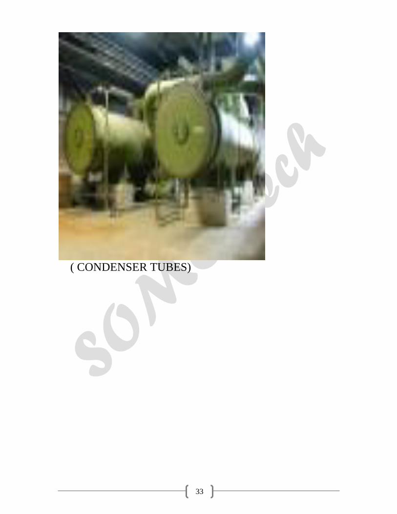
( CONDENSER TUBES)
34
ELECTROSTATIC PRECIPITATOR
Electrostatic Precipitator ESP) is equipment, which utilizes
an intense electric force to separate the suspended particle
from the flue gases. In India coal is widely used to generate
power. The exhaust gases from the furnace contains large
amount of smoke and dust. If these gases are emitted
directly into the atmosphere, it will cause great
environmental problems. So it is necessary to extract this
dust and smoke before emitting the exhaust gases into
atmosphere. There are various methods of extracting dust
but electrostatic precipitator is the most widely used. It
involves electric changing of suspended particles,
collection of charge particles and removal of charged
particles from collecting electrodes. Its various other
advantages are as follows:
1. It has high efficiency i.e. about 99%
2. Ability to treat large volume of gases at high
temperature.
3. Ability to cope with the corrosive atmosphere.
4. It offers low resistance to the flow of gases.
5. It requires less maintenance.
Working Principle:
The electrostatic precipitator utilizes electrostatic forces to
separate dust particles from the gases to be cleaned. The
gas is passed through a chamber, which contains steel
plates (vertical) curtains. These steel curtains divide the
chamber into number of parallel paths. The framework is
held in place by four insulators, which insulate it
electrically from all parts, which are grounded. A high

35
voltage direct current is connected between the framework
and the ground, thereby creating strong electric field
between the wires in the framework curtains.
Strong electric field develops near the surface of wire
creates Corona Discharge along the wire. Thus ionized gas
produces +ve and –ve ions.
In the chamber plates are positively charged whereas the
wire is negatively charged. Positive ions are attracted
towards the wire whereas the negative ions are attracted
towards the plates. On their way towards the curtains
negative ions strike the dust particles and make them
negatively charged. Thus ash is collected on the steel
curtain.
The whole process is divided into the following parts:
1. Corona Generation.
2. Particle Charging.
3. Particle Collection.
4. Particle Removal.
Corona Generation: Corona is a gas discharge
phenomenon associated with the ionization of gas
molecules by electron collision in regions of high
electric filed strength. This process requires non-
uniform electric filed, which is obtained by the use of
a small diameter wire as one electrode and a plate or
cylinder as the other electrode. The corona process is
initiated by the presence of electron in strong electric
field near the wire. In this region of corona discharge,
36
there are free electrons and positive ions. Both
positive and negative coronas are used in industrial
gas cleaning.
In case of negative corona, positive ions generated are
attracted towards the negative electrode or wire and
the electrons towards collecting plates. On impact of
negative ion thus generated, moves towards the
collecting electrodes and serve as principle means of
charging dust.
Particle Charging: There are two physical mechanisms
by which gas ions impact charge to dust particles in
the ESP. Particles in an electric fields causes localized
distortion in an electric filed so that electric field lines
intersect with the particles. The ions present in the
filed tend to travel in the direction of maximum
voltage gradient, which is along electric field lines.
Thus ions will be intercepted by the dust particles
resulting in a net charge flow to the dust particles. The
ions will be held to the dust particles by an induced
image charge force between the ion and dust particle
and become charged to a value sufficient to divert the
electric field lines from particles such that they do not
intercept.
Particle Collection: The forces acting on the charged
particles are Gravitational, Inertial, Electrostatic and
Aerodynamically. The flow of gas stream is turbulent
flow because it causes the particles to flow in random
path through ESP. Particles will be collected at
boundary layers of collector pates. But if flow is
laminar, charge will act on particles in the direction of

37
collecting electrode. This force is opposite to viscous
drag force and thus in the short time, particle would
achieve Terminal (Migration) velocity at which
electrical and viscous forces are equal. Thus the flow
of the charged particles is decided by the vector sum
of these forces i.e. Turbulent.
Particle Removal: In dry removal of dust collected on
plates, Rapping Mechanism is used. It consists of a
geared motor, which moves a long
shaft placed near the support collector electrode and is
provided with cylindrical hammer. On rotating of shaft
these hammers strikes the supports causes plates to
vibrates and dust is removed from plates. Removed
dust is collected in the Hoppers below the precipitator.
At the time of starting of precipitation of dust from
flue gases, the hoppers are at normal temperature bur
the ash collected is very hot. So there is a chance of
ash deposit at the exit of the hopper thus causing
problem of removing the ash. To avoid this, heaters
are provided which increase the temperature at the exit
point of the hopper thus avoiding any undue
accumulation of ash at starting. In order method, the
water is allowed to flow down the collector electrode
and hence dust is collected in hoppers below.
38
General Description:
The whole Electrostatic Precipitator is divided
into following two parts:
Mechanical System.
Electrical System.
Mechanical system: Mechanical system comprises of
Precipitator Casing, Hopper, Collecting and emitting
system, and Rapping mechanism, Gas Distribution
System.
Precipitator Casing:
Precipitator Casing is made of 6mm mild steel plate with
required stiffness. The precipitator casing is all welded
construction comprising of pre-fabricated walls and
proof-panels. The roof carries the precipitator internals,
insulator housing, transformer etc. Both emitting and
collecting systems are hung from the top of the casing.
Emitting and Collecting System: Emitting System is
the most essential part of ESP. Emitting system
consists of rigid emitting frame suspended from four
points on the top and emitting electrodes in the form
of open spiral. The four suspension points are
supported on support insulators to give electrical
insulation to the emitting frame. The frame is designed
to take up the retention forces of the emitting
electrode. The emitting electrodes consist of hard
drawn spiral wires and are fastened with hooks to the
discharge frame.
39
Collecting system mainly consists of collecting
suspension frame, collecting electrodes and shock
bars. Collecting electrodes are made of 1.6mm thick
Mild Steel sheets formed in ‘G’ Profile of 400mm
width. Hook and guide are welded on one end and
shock iron on the other end on a fixture. The
electrodes are bundled together and dipped in rust
preventive oil tank. Collecting electrodes bundles are
properly bundled in order to avoid any damage to
electrodes.
Hoppers: Hoppers are seized to hold the ash for 8-
hour collection and is provided under the casing of
ESP. It is of Pyramidal Shape and is 56 in number. It
is preferred to evacuate the hoppers at the earliest as
long storage of dust in hopper leads to clogging of
hopper. Also at the bottom of hopper electrical heating
is provided to avoid any condensation, which could
also lead to clogging of hopper. Baffle plates are
provided in each hopper to avoid gas leakage.
40
DUST COLLECTING HOPPER WITH PNEUMATIC
SYSTEM
& SLURRY PUMP
Rapping Mechanism: During electrostatic
precipitation a fraction of the dust will be collected on
the discharge electrodes and the corona will be
suppressed as the dust layer grows. So, rapping is
done in order to remove this dust by hammering the
electrodes. As the shaft rotates the hammer tumbles on
to the shock bar that transmits the blow to the
electrode. The whole rapping mechanism is mounted
on a single shaft, which is coupled with the gear drive
motor. The rapping system avoids the collection of ash
on the collecting electrode.
Specification:
Voltage and Current 415V and 5Amp.
Power and Speed 3.7KW and 710
rpm.
Gas Distribution System: The good performance of
the ESP depends on even distribution of gas over
entire cross section of field. Gas Distribution System
distributes the gas evenly in ESP and maintains its
efficiency.
Electrical System: In precipitator we require high
voltage dc supply to generate sufficient electric
field. Electrical system comprises of High Voltage
transformer Rectifier (HVR) unit with Electronic
Controller (EC), Auxiliary control panel, Safety
Interlocks and Field equipments.
41
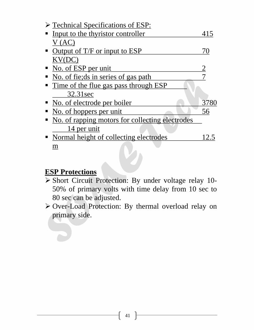
Technical Specifications of ESP:
Input to the thyristor controller 415
V (AC)
Output of T/F or input to ESP 70
KV(DC)
No. of ESP per unit 2
No. of fie;ds in series of gas path 7
Time of the flue gas pass through ESP
32.31sec
No. of electrode per boiler 3780
No. of hoppers per unit 56
No. of rapping motors for collecting electrodes
14 per unit
Normal height of collecting electrodes 12.5
m
ESP Protections
Short Circuit Protection: By under voltage relay 10-
50% of primary volts with time delay from 10 sec to
80 sec can be adjusted.
Over-Load Protection: By thermal overload relay on
primary side.

42
COAL MILL
Coal mills are mainly used to cursed the coal. It cursed the
coal in powder form.
The powder form o coal is known as scream. In the Unit-5,
6 coal mills are present in the unit. In which 5 are working
& I is standby.
CONSTRUCTION:
1. It have three roller, which are inclined at 120 degree
angle to each other.
2. A whirl shaft is mounted on a motor. It makes 1400
r.p.m.
3. A-550 H.P. Motor used for rotation. It attached with
shaft & it also attached with a gear, which further
transfer power to three roller and gives motion.
4. Masinly three type bearing are used:
a. Radial b. Thrust c. Radial support
A pump is used for the lubrication oil, to transfer in the
bearing & gear.
5. A gland is provided to prevent the leakage of oil & a
indicator which gives indication of oil motion.
6. A inlet pipe, coming from coal bunker is feed the coal
in the mill
43
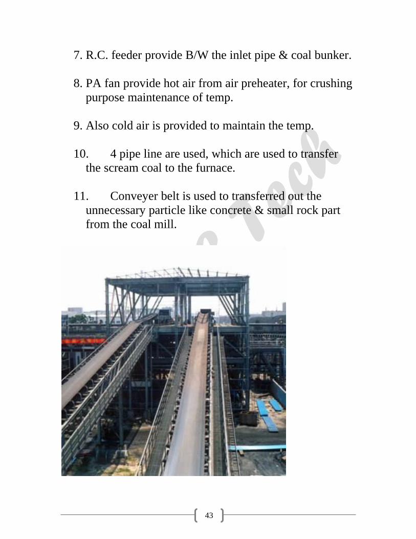
7. R.C. feeder provide B/W the inlet pipe & coal bunker.
8. PA fan provide hot air from air preheater, for crushing
purpose maintenance of temp.
9. Also cold air is provided to maintain the temp.
10. 4 pipe line are used, which are used to transfer
the scream coal to the furnace.
11. Conveyer belt is used to transferred out the
unnecessary particle like concrete & small rock part
from the coal mill.
44
COAL HANDLING PLANT - COAL MILL
WORKING:
Coal coming from CHM to coal bunker, which in small
feed able parts. RC feeder control the feeds of the coal in
the mill, three roller crushed the coal like as scream (as a
powder form). Hot air supplied by PA fan help to crush the
coal & cold air maintain temp.
Gear present at the bottom is prevent the jamming by
giving motion to the powder coal.PA fan maintain
sufficient transfer pressure & the coal from 4 outlet pipe is
given to the furnace.
ASH HANDLING PALNT
It is very import to control the ash coming from the
furnace.
1. WET ASH HANDLING SYSTEM
2. DRYASH HANDLING SYSTEM
A pipe line from ESP which contain the ash in divided in
two parts. Use of Dry ash Evacuation instead of WET
deashing System: Dry deashing system consumers less
power & also minimizes waste reduction.
The dry ash is directly transferred by vacuum system at
desired place in plant it transfer to nearest cement factory.
It is act as a good source of income for the plant.

45
The wet ash is transferred to the wet ash handling, in this
vacuum created by water flow. Ash mix with the water and
transferred to the ash pump from there it is drain out from
the plant in to the lake. From here it is given to the raw
water storage.
Ash handling system
The fly ash handling system evacuates the fly ash from the
hopers, and transports the fly ash to reprocessing or to
disposal. The ash handling system should be designed and
operated to remove the collected fly ash from the hoppers
without causing re-entertainment into the gas flow through
the precipitator. The design of the ash handling system
should allow for flexibility of scheduling the hopper
discharges according to the fly ash being collected in these
hoppers.
Fly ash collection
Fly ash is captured and removed from the flue gas by
electrostatic precipitators or fabric bag filters (or sometimes
both) located at the outlet of the furnace and before the
induced draft fan. The fly ash is periodically removed from
the collection hoppers below the precipitators or bag
filters. Generally, the fly ash is pneumatically transported
to storage silos for subsequent transport by trucks or
railroad cars.

46
Bottom ash collection and disposal
At the bottom of every boiler, a hopper has been provided
for collection of the bottom ash from the bottom of the
furnace. This hopper is always filled with water to quench
the ash and clinkers falling down from the furnace. Some
arrangement is included to crush the clinkers and for
conveying the crushed clinkers and bottom ash to a storage
site.
WATER CLARIFIER
It received impure water from raw water storage. In raw
water storage big suspended particle settle down.
CANAL – RAW WATER STORAGE – LAKE –
WATER CLARIFIER
In water clarifier the purification of raw water held in two
process.
1. Coagulation
2. Chlorination
In coagulation Potash alum is added in the water. In this
process the file suspended & colloidal particles are
removed from water.
In chlorination chlorine gas is added to the water, which
have disinfectant action & it kills the harmful bacteria,
germs & destroyed the pathogenic micro organism.

47
Excess of chlorine in water will effect to the taste of water.
D.M. PLANT
In the DM Plant the water is D-mineralized.
The water is used for steam generation is must be free from
colloidal & dissolved impurities.
All the colloidal impurities are removed in the WATER
CLARIFIER. Then the supplied to the DM Plant.
Water clarifier – DM PLANT
Here the water contain dissolved impurities, which are
mainly the salt of Ca, Na & Mg. It mainly sulphates &
chloride etc
CaSo4, NaCl, CaCl2 etc.
In the DM Water Ist sent to the Sand filter & rest of the
colloidal impurities are removed.
Sand filter – AC filter – Cation tank- Gas tower – Anion
tank
Now the water goes to the Activated Carbon filter. Here
the excess of the chlorine is decomposed.

48
Then water supplied in the cation tank & in this cation
(Ca++, Na+ , Mg++) are removed & water with anion
allow to pass ahead.
R-H+ + NaCl R Na + H Cl
HCl is added time to time to improve the conc. Of the
cation tank. The process is known as the Regeneration .
Then it allow to pass from the gas tower which removed
the Co2 which producred during the purification process.
Then it pass from the anion tank & all the anion Cl -, So4- -
are removed out. Also regeration are done by adding any
base solution , like NaOH etc.
At last it passed in the mixed bed all the minerals present in
the water removed & the water is completely free from
minerals.
STEAM CONDITION : Tri sodium phosphate & ammonia
is added to maintain the pH of the water at specified value.
Also another chemical N2H4 to remove the dissolved
oxygen present in the water.
Air Pre-heater
Regenerative air pre-heaters cause temperature and SO3
stratification in the downstream gas flow. This problem is
more severe in closely coupled systems, where the
precipitator is located closed to the air preheater.

49
Depending upon site-specific conditions, flow mixing
devices may be installed in the ductwork to the precipitator,
or flue gas conditioning systems may be used to equalize
the gas flow characteristics.
Coal Burner
The operation of coal burners, together with the setting of
the coal mills and their classifiers, affects the percentage of
unburned carbon (LOI or UBC) in the fly ash. The use of
Lo-NOx burners increases this percentage, and caused re-
entertainment and increased sparking in the precipitator.
Further, the UBC tends to absorb SO3, which in turn
increases the fly ash resistivity. Over-fire air optimization
or coal-reburn systems may reduce UBC in the fly ash.
CHIMNEY :
The gases produced due to burning of coal are comes out
from chimney. The height of chimney is designed with
respect to the boiler layout.
The temp. is also maintained in the chimney. It is not more
than 120 c.
If it more than 120 c, then boiler will be corrupt..
Fly Ash and Flue Gas Conditioning
Flur gas and fly ash characteristics at the inlet define
precipitator operation. The combination of flue gas
analysis, flue gas temperature and fly ash chemistry
50
provides the base for fly ash resisttivity involves both
surface and volume resistivity. As gas temperature
increases, surface conductivity decreases and volume
resistivity increases.
In lower gas temperature ranges, surface conductivity
predominates. The current passing through the precipated
fly ash layer is conducted in a film of weak sulfuric acid on
the surface of the particles. Formation of the acid film
(from SO3 & H2O) is influenced by the surface chemistry
of the fly ash particles.
In higher gas temperature ranges, volume conductivity
predominates. Current conduction through the bodies
(volume) of the precipitated fly ash particles is governed by
the total chemistry of the particles.
Fly ash resistivity can be modified (generally with the
intent to reduce it ) by injecting one or more of the
following upstream of the precipitator.
Sulfur trioxide (SO3)
Ammonia (NH3)
Water

51
Functions of various parts of the cycle
P.A. FANS:
These fans are used to supply the hot air in order to dry
powdered coal. To transport pulverized coal to the furnace
the speed of PA fans 1400 rpm and they supply 83800 m3
per hour. These are installed either side of boiler
Air Heater:
It is an essential part of a thermal power plant as hot air is
necessary for rapid and efficient combustion in the furnace
and also for drying coal in the milling plant. At PTPS
tabular type air heater are being used it consists of large
number of steel type welded to the tube plates at the end.
Gas is allowed to flow through the tubes and cold air passes
around these tubes and gets heated up. These air heaters
provide primary as well as secondary air.

52
Secondary Air cycle
In this cycle FD FANS suck air from the atmosphere and
supply it to the wind box of the furnace through air heater
and regulating dampers. Then it moves to the furnace as per
requirements.
Function of various parts
F.D FANS
These are used to take air from the atmosphere at ambient
temp. to supply it to the furnace for combustion purpose.

53
Speed is about 990 r.p.m and it handles 203760 m3 of air
per hour
These are installed either side of boiler
WIND BOX
This acts as distributing media for supplying secondary and
excess air to combustion chamber. These are generally
located at right and left side of the furnace while facing the
chimney.

54
INDUCED DRAFT FANS (ID FANS)
These are used to suck the flues gases from the furnace and
through it into the stack so as to dispose them off into the
atmosphere.
It handles flash laden gases at a temp. Of 125 to 200degrees
Its speed is around 970 rpm and it handles 453600 m3 of air
per hour
These are installed at the outlet of electrostatic precipitator.
Related Documents


