This chapter covers the following topics: • The Origins of Multiservice ATM • Next-Generation Multiservice Networks • Multiprotocol Label Switching Networks • Cisco Next-Generation Multiservice Routers • Multiservice Core and Edge Switching

Welcome message from author
This document is posted to help you gain knowledge. Please leave a comment to let me know what you think about it! Share it to your friends and learn new things together.
Transcript

This chapter covers the following topics:
• The Origins of Multiservice ATM
• Next-Generation Multiservice Networks
• Multiprotocol Label Switching Networks
• Cisco Next-Generation Multiservice Routers
• Multiservice Core and Edge Switching

C H A P T E R 3
Multiservice NetworksMultiservice networks provide more than one distinct communications service type over the same physical infrastructure. Multiservice implies not only the existence of multiple traffic types within the network, but also the ability of a single network to support all of these applications without compromising quality of service (QoS) for any of them.
You find multiservice networks primarily in the domain of established service providers that are in the long-term business of providing wireline or wireless communication-networking solutions year after year. Characteristically, multiservice networks have a large local or long-distance voice constituency and are traditionally Asynchronous Transfer Mode (ATM) Layer 2-switched in the core with overlays of Layer 2 data and video solutions, such as circuit emulation, Frame Relay, Ethernet, Virtual Private Network (VPN), and other billed services. The initial definition for multiservice networks was a converged ATM and Frame Relay network supporting data in addition to circuit-based voice communications. Recently, next-generation multiservice networks have emerged, adding Ethernet, Layer 3 Internet Protocol (IP), VPNs, and Multiprotocol Label Switching (MPLS) services to the mix. IP and, perhaps more specifically, IP/MPLS core networks are taking center stage as multiservice networks are converging on Layer 2, Layer 3, and higher-layer services.
Many provider networks were built piecemeal—a voice network here, a Frame Relay network there, and an ATM network everywhere as a next-generation voice transporter and converged platform for multiple services. The demand explosion of Internet access in the 1990s sent many providers and operators scrambling to overlay IP capabilities, often creating another distinct infrastructure to operate and manage. Neither approach used the current investment to its best advantage.
This type of response to customer requirements perpetuates purpose-built networks. Purpose-built networks are not solely a negative venture. These networks do serve their purpose; however, their architectures often overserve their intended market, lack sufficient modularity and extensibility, and, thus, become too costly to operate in parallel over the long term. Multiple parallel networks can spawn duplicate and triplicate resources to provision, manage, and maintain. Examples are resource expansion through additional parts sparing, inimitable provisioning and management interfaces, and bandages to the billing systems. Often a new network infrastructure produces an entirely new division of the company, replicating several operational and business functions in its wake.

104 Chapter 3: Multiservice Networks
The new era of networking is based on increasing opportunity through service pull, rather than through a particular technology push requiring its own purpose-built network infrastructure. Positioning networks to support the service pull of IP while operationally converging multiple streams of voice, video, and IP-integrated data is the new direction of multiservice network architecture. In the face of competitive pressures and service substitution, not only are next-generation multiservice networks a fresh direction, they are an imperative passage through which to optimize investment and expense.
In this chapter, you learn why the industry initially converged around ATM; about next-generation multiservice network architectures that include Cisco multiservice ATM platforms, IP/MPLS routing and switching platforms, and multiservice provisioning platforms; and about multiservice applications that converge data, voice, and video.
The Origins of Multiservice ATMIn the early 1980s, the International Telecommunication Union Telecommunication Standardization sector (ITU-T) and other standards organizations, such as the ATM Forum, established a series of recommendations for the networking techniques required to implement an intelligent fiber-based network to solve public switched telephone network (PSTN) limitations of interoperability and internetwork timing and carry new services such as digital voice and data. The network was termed the Broadband Integrated Services Digital Network (B-ISDN). Several underlying standards were developed to meet the specifications of B-ISDN, including synchronous optical network (SONET) and Synchronous Digital Hierarchy (SDH) as the data transmission and multiplexing standards and ATM as the switching standard. By the mid-1990s, the specifications for the ATM standard were available for manufacturers.
Providers began to build out ATM core networks on which to migrate the PSTN and other private voice networks. Partly justified by this consolidation of the voice infrastructure, the ATM core was positioned as a meeting point and backbone carrier for the voice network products and the Frame Relay data networks. ATM networks were also seen as enablers of the growing demand for multimedia services. Designed from the ground up to provide multiple classes of service, ATM was purpose-built for simultaneous transport of circuit voice, circuit-based video, and synchronous data.
ATM was not initially designed for IP transport but rather was designed as a multipurpose, multiservice, QoS-aware communications platform. It was primarily intended for converging large voice networks, H.320 video networks, and large quantities of leased-line, synchronous, data-based services. ATM theory was heralded as the ultimate answer to potentially millions of PC-to-PC, personal videoconferencing opportunities. It was anticipated that its fixed, cell-based structure would be easily adaptable to any type of data service, and, indeed, adaptation layers were designed into ATM for transport of IP and for LAN emulation.

The Origins of Multiservice ATM 105
In essence, ATM was part of a new PSTN, a new centrally intelligent, deterministic pyramid of power that was expected to ride the multimedia craze to mass acceptance. As such, many service providers who needed a core upgrade during the 1990s chose ATM as a convergence platform and launch pad for future services.
ATM is a system built on intelligence in switches and networks. In contrast, IP-based products are built on intelligence in the core and intelligence distributed to the edges of networks, primarily in customer edge computers that summon or send data at their master’s will. In fact, it is the bursty, variable, free-roaming data characteristics of IP that effectively cripple the efficiency of ATM for IP data transport.
Running IP packets through the ATM Adaptation Layers (AALs) creates a hefty overhead referred to as the ATM cell tax. For example, an IP packet of approximately 250 bytes will need to be chopped and diced into several 48-byte payloads (5-byte ATM header per cell for 53 total bytes), and the last cell will need to be padded to fill out the full data payload, the padding becoming extra overhead. A 250-byte IP packet using an AAL5 Subnetwork Access Protocol (SNAP) header, trailer, and padding swells to 288 bytes with a resulting cost of about 15.2 percent overhead per packet. The shorter the length of an IP packet, the larger the percentage of overhead. TCP/IP is all over the map—size wise—with many data packets, especially acknowledgements, shorter than 100 bytes. Using ATM Inverse Multiplexing over ATM to bond T1 circuits for a larger bandwidth pool in ATM networks imposes significant, additional overhead. Adding it all up, the total fixed and variable cell tax overhead can be decimating to linkage of IP traffic.
Back in the late 1990s when IP networks were coming on very strong, ATM products for enterprises cost about twice as much as Ethernet-based products, cost twice as much to maintain, and were intensive to configure and operate due to the ATM addressing structure and virtual circuit mesh dependencies. ATM was just too expensive to purchase and maintain (more tax) to extend to the desktop, where it could converge voice, video, and data.
ATM initially entered the WAN picture as the potential winner for multiple services of data, video, and voice. As with any new technology, the industry pundits overhyped the technology as the answer to every networking challenge within the provider, enterprise, and consumer markets. As IP networks continued to grow, and voice and video solutions were adapted to use IP over Fast and Gigabit Ethernet optical fiber spans, the relevance of ATM as a universal convergence technology waned.
Due to ATM’s complexity of provisioning, its high cost of interfaces, and its inherent overhead, ATM gravitated to the niche bearers of complex skill sets, such as in service provider core networks, in large enterprise multiservice cores, and as occasional backbone infrastructure in LAN switching networks. ATM has also been a well-established core technology for traditional tandem voice operators and as backhaul for wireless network carriers. Much like ISDN before it, the technology push of ATM found a few vertical markets but only along paths of least resistance.

106 Chapter 3: Multiservice Networks
From a global network perspective, the ascendancy of IP traffic has served ATM notice. According to IDC, worldwide sales of ATM switches were down 21 percent in 2002, another 12 percent in 2003, and nearly 6 percent through 2004. Further, IDC forecasts the ATM switch market to decline at roughly 8 percent per year during the 2006 to 2009 timeframe.1
With the Digital Subscriber Line (DSL) deployments by the Incumbent Local Exchange Carriers (ILECs), ATM networks moved into the service provider edge, extending usefulness as broadband aggregation for the consumer markets. DSL has been an important anchor for ATM justification, bridging consumer computing to the Internet, but even there, DSL technology is signaling a shift to Ethernet and IP. The DSL Forum has presented one architecture that would aggregate DSL traffic at the IP layer using IP precedence for QoS rather than at the ATM layer. In Asia, many DSL providers already use Ethernet and IP as the aggregation layer for DSL networks, benefiting from the lower cost per bit for regional aggregation and transport.
Soon, ATM switching will likely be pushed out of the core of provider networks by MPLS networks that are better adapted to serve as scalable IP communications platforms. In fact, many providers have already converged their Frame Relay and ATM networks onto an MPLS core to reduce operational expenditures and strategically position capital expendi-tures for higher margin, IP-based services. ATM will settle in as a niche, edge service and eventually move into legacy support.
However, for providers that still have justifiable ATM requirements, there remains hope by applying next-generation multiservice architecture to ATM networks, which you learn about in the next section. Because providers cannot recklessly abandon their multiyear technology investments and installed customer service base, gradual migration to next-generation multiservice solutions is a key requirement. However, the bandwidth and services explosion within the metropolitan area, from 64 Kbps voice traffic to 10 Gigabit Ethernet traffic, is accelerating the service provider response to meet and collect on the opportunity.
Figure 3-1 shows a representative timeline of multiservice metropolitan bandwidth requirements. Through the 1980s and into the 1990s, bandwidth growth was relatively linear, because 64 Kbps circuits (digital signal zero or DS0) and DS1s (1.5 Mbps) and DS3s (45 Mbps) were able to address customer growth with Frame Relay and ATM services. The Internet and distributed computing rush of the late 1990s fueled customer requirements for Gigabit Ethernet services, accelerating into requirements for multigigabit services, higher-level SONET/SDH services, and storage services moving forward. The bandwidth growth opportunity of the last ten years is most evident in the metropolitan areas where multiservice networks are used.

Next-Generation Multiservice Networks 107
Figure 3-1 Primary Metropolitan Traffic Timeline
Source: Cisco Systems, Inc.
Next-Generation Multiservice NetworksTraditional multiservice networks focus on Layer 2 Frame Relay and ATM services, using a common ATM backbone to consolidate traffic. This generation of ATM switches was easily extended to support DSL and cable broadband build-outs.
In contrast, next-generation multiservice networks provide carrier-grade, Layer 3 awareness, such as IP and MPLS, in addition to traditional Layer 2 services. These next-generation multiservice networks can take the form of ATM-, blended IP+ATM-, IP/MPLS-, or SONET/SDH-based networks in order to deliver multiple traffic services over the same physical infrastructure.
Even with the existence of next-generation technology architectures, most providers are not in a position to turn over their core technology in wholesale fashion. Provider technology is often on up-to-decade-long depreciation schedules, and functional life must often parallel this horizon, even if equipment is repurposed and repositioned in the network. Then there is the customer-facing issue of technology service support and migration. Though you might wish to sunset a particular technology, the customer is not often in support of your timetable. This requires a measured technology migration supporting both heritage services along with the latest service features. Next-generation technology versions are often the result, to allow new networking innovations to overlap established network architectures.
The topics of next-generation multiservice switching, Cisco next-generation multiservice ATM switches, and MPLS support on Cisco ATM switches are discussed next.
Primary Metro Traffic
Voice Circuits,Modem Traffic
DS0s DS1s and DS3sSTS/VC4-n,
Up to OC-192/STM-64
1980s
Moving from Centralized to Distributed
1990s 2000–2004 2005+
FR andATM Growth
Gigabit Ethernetand Storage
Multi-GigServices
108 Chapter 3: Multiservice Networks
Next-Generation Multiservice ATM SwitchingNext-generation multiservice ATM switching is often defined by a common transmission and switching infrastructure that can natively provide multiple services in such a manner that neither service type interferes with the other. This independence between different ser-vices requires a separation of the control and switching planes in multiservice equipment. The control plane acts as the brain, apportioning resources, making routing decisions, and providing signaling, while the switching plane acts as the muscle machine, forwarding data from source to destination.
Separation of the control and switching planes makes it possible to partition the resources of the switching platform to perform multiple services in a native fashion. In much the same way that you can logically partition an IBM mainframe processor into multiple production operating systems, apportioning CPU cycles, memory, storage, and input/output channels to individual logical partitions (LPARs), you can resource partition next-generation multiservice switches to accomplish the same concept of creating multiple logical network services.
Resource portioning in many of the next-generation multiservice switches is accomplished through a virtual switch interface within the control and switching planes. Through a function such as the virtual switch interface, you can have multiple service controllers, each sharing the control plane resources to manage the switching plane, which is the switch fabric that forwards data between a source port and a destination port.
Within the Cisco MGX line of multiservice switches, the virtual switching instance (VSI) allows for an ATM Private Network to Network Interface (PNNI) controller to act as a virtual control plane for ATM services, an MPLS controller to act as a virtual control plane for IP or ATM services, and a Media Gateway Control Protocol (MGCP) controller to act as a virtual control plane for voice services. Each type of controller, through Cisco VSI, directs the assigned resources and interfaces of the physical ATM switch that have been partitioned within its domain of control.
You can run all three controllers and, therefore, multiple services in the same physical ATM switch. If partitioned on a switch, each of these service types is integrated natively and not running as a technology overlay. For example, when running MPLS over an ATM switching fabric, all the network switches run an IP routing protocol and an MPLS label distribution protocol (LDP), which is in contrast to running IP as an overlay via classic ATM permanent virtual circuits (PVCs). Every switch in the MPLS-enabled multiservice network is aware of the multiple services that it provides. The multiple controller capability can allow for a migration from classic ATM switching to MPLS within the same physical architecture.
Figure 3-2 shows the conceptual representation of the Cisco Virtual Switch Architecture. The virtual switch architecture is a Switch Control Interface (SCI) developed by Cisco Systems, Inc., and implemented in the Cisco MGX product line of multiservice switching platforms. The virtual switch works across the control and switching planes, the switching plane essentially performs the traffic-forwarding function. While the control plane and the

Next-Generation Multiservice Networks 109
switching plane represent the workhorse functions of the multiservice switch, within the Cisco design there is also an adaptation plane, a management plane, and an application plane that completes the multiservice system architecture. An example of a requirement for the adaptation plane would be the inclusion of support for Frame Relay services, the adaptation plane facilitating the use of Frame Relay to ATM service interworking. A management plane is required for overall switch control, configuration, and monitoring.
Figure 3-2 Cisco Virtual Switch Architecture
Source: Cisco Systems, Inc.
The advantages of next-generation multiservice switching are as follows:
• Multiple service types of ATM, voice, MPLS, and IP are supported on the same physical infrastructure, allowing the provider to leverage both circuit-based and packet-based revenue streams.
• Control plane independence allows you to upgrade or maintain one controller type independently, without interrupting service for other controllers.
• You have the ability to choose and implement a control plane that is best suited to the application requirements.
• The separation of the control and switching planes allow the vendor to develop functional enhancements independently of each other.
• The cost-effective approach of adding MPLS to ATM switch infrastructure allows for the migration to MPLS as a common control plane.
PNNIController
MPLSController
Switching Fabric
Standard IN/Signaling APIs,Interfaces, and Protocols
MGCPController
Application Plane
Cisco Virtual Switch Architecture
Man
agem
ent
Pla
neControl Plane
Virtual Switch Control Function
Virtual Switch Function
Logical Port Function
Forwarding Plane
Adaptation Plane VoIPIP VoATM TDM FR ATM

110 Chapter 3: Multiservice Networks
Using next-generation multiservice ATM architectures, providers can maintain existing ser-vices such as circuit-based voice and circuit-based video, while migrating to and imple-menting new packet-based network services such as packet voice, Layer 2 and Layer 3 VPNs, MPLS, and MPLS traffic engineering features. Many providers will maintain ATM infra-structures and might need to bridge from a traditional ATM platform to a next-generation multiservice ATM platform. As an example, Figure 3-3 shows the concept of migrating a Layer 2, full-mesh PVC network to a next-generation multiservice ATM network that uses MPLS rather than discreet PVCs. By adding a Route Processor Module (RPM) to the MGX 8800s in the figure, this next-generation multiservice ATM platform can support Layer 3 IP protocols, and use MPLS to get the best benefits of both routing and switching.
Cisco Next-Generation Multiservice SwitchesUsing next-generation multiservice network architecture, Cisco offers several solutions that support today’s revenue-generating services while accelerating the delivery of new high-value IP-based services. By combining Layer 3 IP and Layer 2 ATM in a straightforward and flexible manner, providers can establish networks that support existing and emerging services. This provides carrier-class data communication solutions that free providers from the economic and technical risks of managing complex multiservice networks.
Cisco implements next-generation multiservice capabilities in the following products:
• Cisco BPX 8600 Series Switches
• Cisco MGX 8250 Series Switches
• Cisco MGX 8800 Series Switches
• Cisco MGX 8900 Series Switches
• Cisco IGX 8400 Series Switches
The next sections describe and compare these Cisco switches.
Cisco BPX 8600 Series SwitchesThe Cisco BPX 8600 Series Multiservice Switches are IP+ATM platforms providing ATM-based broadband services and integrating Cisco IOS to support MPLS and deliver IP services. The heart of the system is a 19.2 Gbps cross-point switching fabric capable of switching up to two million cells per second, in a multislot chassis. The chassis employs a midplane design, allowing front cards to be adapted to a variety of back cards that provide Layer 1 interface connections such as T3/E3, OC-3/STM-1, and OC-12/STM-4 (622 Mbps). The largest BPX node has a modular, multishelf architecture that scales up to 16,000 DS1s. With heritage from the Cisco acquisition of Stratacom, the BPX switches are often deployed as carrier-class core switches or broadband edge switches in voice, Frame Relay, ATM, wireless, and MPLS provider networks, where OC-12 core links can supply appropriate capacity.

Next-Generation Multiservice Networks 111
Figure 3-3 Network Migration from Layer 2 to Next-Generation Multiservice ATM Networks
Source: Cisco Systems, Inc.
Cisco MGX 8800s
Layer 2 NetworkPVCs
Cisco BPX8620s
Cisco MGX 8800swith RPM
Cisco MGX 8800sMultiservice Network
MPLS
Cisco BPX8650s

112 Chapter 3: Multiservice Networks
Cisco MGX 8250 Edge Concentrator SwitchThe Cisco MGX 8250 Edge Concentrator is a multiservice switch used primarily at the service provider edge supporting narrowband services at 1.2 Gbps of switching capacity. Supporting T1/E1 to OC-12c/STM-4, Ethernet and Fast Ethernet, this switch family is very flexible for providing ATM edge concentration and even MPLS edge concentration where cost-effectiveness is the primary requirement. Switches deployed at the edge of networks need a good balance between port density and cost. The 8250 has 32 card slots for good capacity. A general target for this platform is a maximum capacity of 192 T1s, which would aggregate to 296 Mbps of bandwidth, well under the OC-12/STM-4 uplink capability for this 8250. That leaves bandwidth headroom within the OC-12’s 622 Mbps of capacity to also support several Ethernet and a few Fast Ethernet ports. All port cards support hot insert and removal, allowing the provider to add card and port density incrementally in response to demand.
Cisco MGX 8800 Series SwitchesThe Cisco MGX 8800 Series Multiservice Switches provide significant flexibility at the service provider edge. The Cisco MGX 8800 family is a narrowband aggregation switch with broadband trunking up to OC-48 (2.5 Gbps). The MGX 8800’s cross-point switching fabric options operate at either 1.2 Gbps (PXM-1) or up to 45 Gbps (PXM-45) of nonblocking switching. The aforementioned virtual switch architecture allows for multiple control planes via individual controller cards such as PXM-1E for PNNI services, an RPM-PR controller for IP/MPLS services, and a VISM-PR card for packet voice services using MGCP, packet cable Trunking Gateway Control Protocol (TGCP), H.323 video, and Session Initiation Protocol (SIP).
The 8800 series supports narrowband services of T1/E1 ATM, n * T1/E1 inverse multiplex-ing over ATM (IMA), Frame Relay, high-speed Frame Relay, Systems Network Architec-ture (SNA), circuit emulation, ATM user network interface (UNI) 3.0/3.1, and switched multimegabit data service (SMDS). These are useful for integrating services such as IP VPNs, Voice over IP (VoIP) and ATM, PPP aggregation, managed intranets, premium Internet services, and IP Fax Relay. Supporting 100 percent redundancy and automatic protection switching (APS), the 8800 series is often deployed as an MPLS multiservice ATM switch on the edges of ATM-based provider networks.

Next-Generation Multiservice Networks 113
Cisco MGX 8900 Series SwitchesThe Cisco 8900 Series Multiservice Switch, specifically the 8950, is a high-end multiservice broadband switch designed to scale multiservice networks to OC-192c/STM-64. Support-ing a range of broadband services from T3/E3 to OC-192c/STM-64, the MGX 8950 supports the aggregation of broadband services, scaling of MPLS VPNs, and network convergence.
With up to 180 Gbps of redundant switching capacity or 240 Gbps nonredundant, the MGX 8950 is a superdensity broadband switch supporting up to 768 T3/E3s, 576 OC3c/STM-1s, 192 OC-12c/STM-4s, 48 OC-48c/STM-16s, or up to 12 OC-192c/STM-64s in flexible combinations. This switch is specifically architected with a 60 Gbps switch fabric module (XM-60), of which four can be installed to meet the demands and service levels of 10 Gbps ATM-based traffic at the card interface level. The modularity of the XM-60 module allows a provider to incrementally scale switching capacity as needed, starting with one and growing to four per MGX 8950 chassis.
Cisco IGX 8400 Series SwitchesCisco also has a family of multiservice switches that are designed for large enterprises with ATM requirements or for service providers with low cost of ownership requirements. The IGX 8400 series of multiservice WAN switches support line speeds of 64 Kbps up to OC3c/STM-1 with a 1.2 Gbps nonblocking switching fabric. MPLS is also supported on this IP+ATM switch family. The IGX 8400 represents the lowest cost per port of any ATM switch on the market.
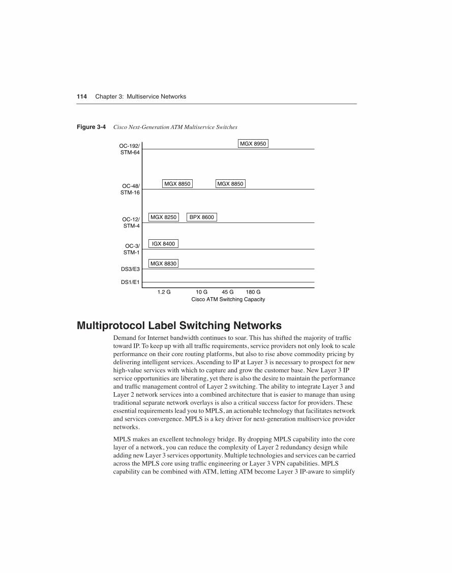
Comparing Cisco Next-Generation ATM Multiservice SwitchesIn summary, the complete family of Cisco multiservice switches support switching speeds from 1.2 Gbps to 240 Gbps, line speeds from DS0 to OC-192c/STM-64 including Fast Ethernet, and ATM edge concentration, PNNI routing, MPLS routing, and packet voice control functions. Both modular and compliant with the various specifications, these products are used to build today’s next-generation multiservice ATM networks. Figure 3-4 shows the relative positioning of Cisco next-generation ATM multiservice switches.
114 Chapter 3: Multiservice Networks
Figure 3-4 Cisco Next-Generation ATM Multiservice Switches
Multiprotocol Label Switching NetworksDemand for Internet bandwidth continues to soar. This has shifted the majority of traffic toward IP. To keep up with all traffic requirements, service providers not only look to scale performance on their core routing platforms, but also to rise above commodity pricing by delivering intelligent services. Ascending to IP at Layer 3 is necessary to prospect for new high-value services with which to capture and grow the customer base. New Layer 3 IP service opportunities are liberating, yet there is also the desire to maintain the performance and traffic management control of Layer 2 switching. The ability to integrate Layer 3 and Layer 2 network services into a combined architecture that is easier to manage than using traditional separate network overlays is also a critical success factor for providers. These essential requirements lead you to MPLS, an actionable technology that facilitates network and services convergence. MPLS is a key driver for next-generation multiservice provider networks.
MPLS makes an excellent technology bridge. By dropping MPLS capability into the core layer of a network, you can reduce the complexity of Layer 2 redundancy design while adding new Layer 3 services opportunity. Multiple technologies and services can be carried across the MPLS core using traffic engineering or Layer 3 VPN capabilities. MPLS capability can be combined with ATM, letting ATM become Layer 3 IP-aware to simplify
MGX 8850
OC-192/STM-64
OC-48/STM-16
OC-12/STM-4
OC-3/STM-1
DS3/E3
DS1/E1
BPX 8600MGX 8250
IGX 8400
MGX 8830
1.2 G 10 G 45 G 180 GCisco ATM Switching Capacity
MGX 8850
MGX 8950

Multiprotocol Label Switching Networks 115
provisioning and management. Because of these attributes, MPLS has momentum as a unifying, common core network, as it more easily consolidates separate purpose-built networks for voice, Frame Relay, ATM, IP, and Ethernet than any methodology that has come before. In doing so, it portends significant cost savings in both provider capital expenditures (CapEx) and operational expenditures (OpEx).
MPLS is an Internet Engineering Task Force (IETF) standard that evolved from an earlier Cisco tag switching effort. MPLS is a method of accelerating the performance and management control of traditional IP routing networks by combining switching functionality that collectively and cooperatively swaps labels to move a packet from a source to a destination. In a sense, MPLS allows the connectionless nature of IP to operate in a more connected and manageable way.
An MPLS network is a collection of label switch routers (LSRs). MPLS can be implemented on IP-based routers (frame-based MPLS) as well as adapted to ATM switches (cell-based MPLS). The following sections discuss MPLS components, terminology, functionality, and services relative to frame-based and cell-based MPLS.
Frame-Based MPLSFrame-based MPLS is used for a pure IP routing platform—that is, a router that doesn’t have an ATM switching fabric. When moving data through a frame-based MPLS network, the data is managed at the frame level (variable-length frames) rather than at a fixed length such as in cell-based ATM. It is worthwhile to understand that a Layer 3 router is also capable of Layer 2 switching.
Frame-Based MPLS Components and TerminologyUnderstanding frame-based MPLS terminology is challenging at first so the following review is offered:
• Label switch router (LSR)—The LSR provides the core function of MPLS label switching. The LSR is equipped with both Layer 3 routing and Layer 2 switching characteristics. The LSR functions as an MPLS Provider (P) node in an MPLS network.
• Edge label switch router (eLSR)—The eLSR provides the edge function of MPLS label switching. The eLSR is where the label is first applied when traffic is directed toward the core of the MPLS network or last referenced when traffic is directed toward the customer. The eLSR functions as an MPLS Provider Edge (PE) node in an MPLS network. The eLSRs are functional PEs that send traffic to P nodes to traverse the MPLS core, and they also send traffic to the customer interface known in MPLS terminology as the Customer Edge (CE). The eLSRs use IP routing toward the customer interface and “label swapping” toward the MPLS core. The term label edge router (LER) is also used interchangeably with eLSR.
116 Chapter 3: Multiservice Networks
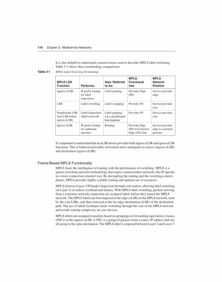
It is also helpful to understand common terms used to describe MPLS label switching. Table 3-1 shows these terminology comparisons.
It’s important to understand that an eLSR device provides both ingress eLSR and egress eLSR functions. This is bidirectional traffic movement and is analogous to source (ingress eLSR) and destination (egress eLSR).
Frame-Based MPLS FunctionalityMPLS fuses the intelligence of routing with the performance of switching. MPLS is a packet switching network methodology that makes connectionless networks like IP operate in a more connection-oriented way. By decoupling the routing and the switching control planes, MPLS provides highly scalable routing and optimal use of resources.
MPLS removes Layer 3 IP header inspection through core routers, allowing label switching (at Layer 2) to reduce overhead and latency. With MPLS label switching, packets arriving from a customer network connection are assigned labels before they transit the MPLS network. The MPLS labels are first imposed at the edge (eLSR) of the MPLS network, used by the core LSRs, and then removed at the far edge (destination eLSR) of the destination path. The use of labels facilitates faster switching through the core of the MPLS network and avoids routing complexity on core devices.
MPLS labels are assigned to packets based on groupings or forwarding equivalency classes (FECs) at the ingress eLSR. A FEC is a group of packets from a source IP address that are all going to the same destination. The MPLS label is imposed between Layer 2 and Layer 3
Table 3-1 MPLS Label Switching Terminology
MPLS LSR Function Performs:
Also Referred to As:
MPLS Functional Use
MPLS Network Position
Ingress eLSR IP prefix lookup for label imposition
Label pushing Provider Edge (PE)
Service provider edge
LSR Label switching Label swapping Provider (P) Service provider core
Penultimate LSR (last LSR before egress eLSR)
Label disposition (label removal)
Label popping a.k.a. penultimate hop popping
Provider (P) Service provider core
Egress eLSR IP prefix lookup for outbound interface
Routing Provider Edge (PE) to Customer Edge (CE) link
Service provider edge to customer premise

Multiprotocol Label Switching Networks 117
headers in a frame-based packet environment, or in the Layer 2 virtual path identifier/virtual channel identifier (VPI/VCI) field in cell-based networks like ATM. The following example presumes the use of frame-based MPLS in the routing of an IP packet.
Customer site “A” sources an IP packet destined for customer site “B” that reaches the ser-vice provider’s eLSR and then performs an ingress eLSR (PE) function. The ingress eLSR examines the Layer 3 IP header of the incoming packet, summarizes succinct information, and assigns an appropriate MPLS label that identifies the specific requirements of the pack-et and the egress eLSR (PE). The MPLS label is imposed or, more specifically, “shimmed” between the Layer 2 and Layer 3 headers of the current IP packet.
Prior to the first packet being routed, the core LSRs (P nodes) have already predetermined their connectivity to each other and have shared label information via an LDP. The core LSRs can, therefore, perform simple Layer 2 label swapping and then switch the ingress eLSR’s labeled packet to the next LSR along the label-switched path, helping the ingress eLSR get the packet to the egress eLSR. The last core LSR (penultimate hop P node) prior to the target egress eLSR removes the MPLS label, as label swapping has served its usefulness in getting the packet to the proper egress eLSR.
The egress eLSR is now responsible for examining the Customer A-sourced Layer 3 IP header once again, searching its IP routing table for the destination port of customer site B and routing the Customer A packet to the Customer B destination output interface. Figure 3-5 shows the concept of frame-based MPLS label switching.
Figure 3-5 Frame-Based MPLS Label Switching
Source: Cisco Systems, Inc.
Packet Flow
SourceRouter
CustomerSite A
Frame-Based MPLS Network
CustomerSite B
IngressLSR
EgressLSRLSR LSR
PenultimateLSR
DestinationRouter
Packet Packet69 Packet56 Packet158 Packet• Packet
MPLS Label ImposedBetween L2 and L3 Headers
LabelImposition
LabelSwapping
LabelSwapping
Penultimate HopHopping
LabelRemoving
118 Chapter 3: Multiservice Networks
Cell-Based MPLS Adding MPLS functionality to ATM switches allows service providers with ATM requirements to more easily deploy Layer 3, high-value IP feature capabilities, supporting MPLS VPNs, MPLS traffic engineering, packet voice services, and additional Layer 3 managed offerings. This is the ultimate definition of next-generation multiservice networks—networks that are capable of supporting circuit-based Layer 2 and packet-based Layer 2 and Layer 3 services on the same physical network infrastructure. By leveraging the benefits of the Cisco IP+ATM multiservice architecture with MPLS, operators are migrating from basic transport providers to service-oriented providers.
MPLS on ATM switches must use the Layer 2 ATM header, specifically the VPI/VCI field of the ATM header. Since this is pure ATM, all signaling and data forwarding is accomplished with 53-byte ATM cells. Therefore, MPLS implementations on the ATM platforms are referred to as cell-based MPLS. Non-ATM platforms such as pure IP-based routers also use MPLS, but that implementation uses frame headers and is referred to as frame-based MPLS, as you learned in the previous section. In the discussion that follows, cell-based MPLS is presumed.
Cell-Based MPLS ATM ComponentsImplementing MPLS capability on the Cisco Multiservice ATM Switches requires the addition of the Cisco IOS software to the ATM switching platforms. This is accomplished through either external routers such as the Cisco 7200 or via a co-controller card (essentially a router in a card form factor) resident in the ATM switch.
To understand the various MPLS implementation approaches, you first need to familiarize yourself with the following MPLS terminology:
• Label switch controller (LSC)—The central control function of an MPLS application in an ATM multiservice network. The LSC contains the following:
— IP routing protocols and routing tables
— The LDP function
— The master control functions of the virtual switch interface
• MPLS ATM label switch router (LSR)—Created by combining the LSC with an ATM switch. In MPLS networks, the LSR can support the function of core switching nodes, referred to as the MPLS Provider (P) node, or function as an eLSR to form an MPLS Provider Edge (PE) node. As an example, the BPX 8620 ATM Multiservice Switch is paired with a Cisco 7200 Router acting as the MPLS LSC, and this combination forms an MPLS ATM LSR. The ATM switch provides the Layer 2 switching function, while the 7200 LSC provides the Layer 3 awareness, routing, and switching control. This combination of the Cisco 7200 LSC, and the BPX 8620 is given a model number of BPX 8650.

Multiprotocol Label Switching Networks 119
• Co-controller card—For MPLS on ATM, this is a router-on-a-card called a RPM. The RPM-PR is essentially a Cisco 7200 Network Processing Engine 400 (NPE-400), and the higher-performance RPM-XF is based on the Cisco PXF adaptive processing architecture. Either style of RPM can be used based on performance requirements. Both Layer 3 RPMs are implemented on a card-based form factor that integrates into the Cisco MGX 8800 and MGX 8900 Series multiservice ATM switches. Since the RPM has control function that complements the base ATM switch controller card (PXM), the RPM is generically referred to as a co-controller card. With MPLS configured on the RPM, these ATM switches become MPLS ATM LSRs.
• Universal Router Module (URM)—This is an onboard Layer 3 Route Processor controller card that is platform-specific terminology for the Cisco IGX 8400 ATM switch. The URM allows the IGX 8400 to participate as an MPLS ATM LSR.
Cell-Based MPLS ATM LSR and eLSR FunctionalityUsing the background terminology information from Table 3-1, it is worthwhile to briefly describe the MPLS ATM LSR and eLSR functionality, examining how they cooperate together to move a packet from customer site “A” to customer site “B” (a unidirectional example). The example is similar in all respects to the frame-based MPLS example, with the exception of the particular header field that is used to carry the MPLS labels, and the fact that fixed-length ATM cells are used between the eLSRs.
Customer site A sources a packet destined for customer site B that reaches the service provider’s eLSR or ATM eLSR and then performs an ingress eLSR function. The ingress eLSR examines the Layer 3 IP header of the incoming packet, summarizes succinct information, and assigns an MPLS label that identifies the egress eLSR. The MPLS label is imposed and placed within the ATM VPI/VCI field of the ATM Layer 2 header. This MPLS label allows IP packets to be label-switched as ATM cells through the core ATM LSRs (P nodes) of the MPLS network without further examination of the IP header until the cells reach the egress eLSR (which reassembles the cells back into packets prior to delivery to customer site B).
The core ATM LSRs have already predetermined their connectivity to each other and have shared label information via an LDP. The core ATM LSRs can, therefore, perform simple Layer 2 label swapping within the ATM VPI/VCI field, converting the ingress eLSR labeled packet to cells and switching the labeled cells to the next P node along the label-switched path, helping the ingress eLSR get the sourced packet to the egress eLSR. The last core ATM LSR (penultimate hop P node) prior to the target egress eLSR removes the MPLS label, as label swapping has served its usefulness in getting the cells to the proper egress eLSR.
The egress eLSR is now responsible for reassembling all cells belonging to the original packet, for examining the Customer A-sourced Layer 3 IP header once again, searching its IP routing table for the destination port of customer site B, and routing the Customer A

120 Chapter 3: Multiservice Networks
packet to the Customer B destination output interface. Figure 3-6 shows the concept of cell-based MPLS label switching.
Figure 3-6 Cell-Based MPLS Label Switching
Source: Cisco Systems, Inc.
One of the caveats of cell-based MPLS is that the use of the fixed-length VPI/VCI field within the ATM Layer 2 header imposes some restrictions on the number of MPLS labels that can be stacked within the field. This can limit certain functionality, such as advanced features within MPLS Traffic Engineering that depend on multiple MPLS labels. It is worthwhile to consult Cisco support for those features, hardware components, and software levels that are supported by cell-based MPLS platforms.
Implementing Cell-Based MPLS on Cisco ATM Multiservice SwitchesYou can use any of the Cisco switches mentioned earlier to perform the function of an eLSR (PE). The BPX 8600 series uses the external Cisco 7200 router in combination to become an MPLS ATM eLSR. The MGX 8800 and 8900 switches use the onboard RPM-PR or RPM-XF co-controller cards for the eLSR function, and the IGX-8400 uses the URM card for the eLSR functionality. All platforms except for the MGX 8250 can also be configured as core LSRs (P nodes). Table 3-2 shows a summary of these MPLS realizations.
Utilizing MPLS, the Cisco next-generation multiservice ATM infrastructure allows the unique features of ATM for transport aggregation to combine with the power and flexibility of IP services.
Packet Flow
SourceRouter
CustomerSite A
Cell-Based MPLS Network
CustomerSite B
IngressLSR
EgressLSRLSR LSR
PenultimateLSR
DestinationRouter
Packet PacketCell69 Cell56 Cell158 Cell•
MPLS Label Imposedin L2 VPI/VCI Field
LabelImposition
LabelSwapping
LabelSwapping
Penultimate HopHopping
LabelRemoving

Multiprotocol Label Switching Networks 121
Functionally, both frame-based and cell-based MPLS eLSRs support Layer 3 routing toward the customer, Layer 3 routing between other eLSRs, and Layer 2 label switching toward the provider core, while the core LSRs provide Layer 2 label switching through the core. You could draw the analogy that an MPLS label is a tunnel of sorts, invisibly shuttling packets or cells across the network core. The core LSRs, therefore, don’t participate in customer routing awareness as a result, reducing the size and complexity of their software-based routing and forwarding tables. This blend of the best features of Layer 3 routing with Layer 2 switching allows MPLS core networks to scale very large, switch very fast, and converge Layer 2 and Layer 3 network services into a next-generation multiservice network.
In summary, both frame-based and cell-based MPLSs provide great control on the edges of the network by performing routing based on destination and source addresses, and then by switching, not routing, in the core of the network. MPLS eliminates routing’s hop-by-hop packet processing overhead and facilitates explicit route computation on the edge. MPLS adds connection-oriented, path-switching capabilities and provides premium service-level capabilities such as differentiated levels of QoS, bandwidth optimization, and traffic engineering.
MPLS ServicesMPLS provides both Layer 2 and Layer 3 services. Layer 2 services include Ethernet and IP VPNs. Ethernet is migrating from LANs to WANs but needs service-level agreement (SLA) capabilities such as QoS, traffic engineering, reliability, and scalability at Layer 2. For example, the ability to run Ethernet over MPLS (EoMPLS) improves the economics of Ethernet-based service deployment and provides an optimal Layer 2 VPN solution in the metropolitan area. Ethernet is a broadcast technology, and simply extending Ethernet over classic Layer 2 networks merely extended all of these broadcasts, limiting scalability of
Table 3-2 MPLS LSR and eLSR Implementation Summary
Cisco Switch Series MPLS ATM LSR (P) MPLS ATM eLSR (PE)
BPX 8600 With external Cisco 7200 With external Cisco 7200
MGX 8250 Not applicable Internal RPM-PR cards
MGX 8850 Internal RPM-PR (up to 350,000 packets per second) or RPM-XF (up to 2 million plus packets per second; requires PXM-45)
Internal RPM-PR or RPM-XF
MGX 8950 Internal RPM-PR or RPM-XF Internal RPM-PR or RPM-XF
IGX 8400 Internal URM or external Cisco 7200
Internal URM or external Cisco 7200

122 Chapter 3: Multiservice Networks
such a service. EoMPLS can incorporate some Layer 3 routing features to enhance Ethernet scalability. MPLS is also access technology independent and easily supports a direct interface to Ethernet without using Ethernet over SONET/SDH mapping required by many traditional Layer 2 networks. Using a Cisco technology called Virtual Private LAN Service (VPLS), an MPLS network can now support a Layer 2 Ethernet multipoint network.
Additional MPLS Layer 2 services include Any Transport over MPLS (AToM). At Layer 2, AToM provides point-to-point and like-to-like connectivity between broadband access media types. AToM can support Frame Relay over MPLS (FRoMPLS), ATM over MPLS (ATMoMPLS), PPP over MPLS (PPPoMPLS), and Layer 2 virtual leased-line services. This feature allows providers to migrate to a common MPLS core and still offer traditional Layer 2, Frame Relay, and ATM services with an MPLS-based network. Both VPLS and AToM are discussed further in Chapter 4, “Virtual Private Networks.”
MPLS Traffic Engineering (MPLS TE) is another MPLS Layer 2 service that allows network managers to more automatically direct traffic over underutilized bandwidth trunks, often forestalling costly bandwidth upgrades until they’re absolutely needed. Since IP routing always uses shortest path algorithms, longer paths connecting the same source and destination networks would generally go unused. MPLS TE simplifies the optimization of core backbone bandwidth, replacing the need to manually configure explicit routes in every device along a routing path. It should be noted that MPLS TE works for frame-based and cell-based MPLS networks; however, in cell-based networks, there are some limitations to the MPLS TE feature set. For example, the ability to combine MPLS TE Fast Re-Route (FRR) isn’t supported, as it requires additional labels. MPLS TE using FRR would require multiple labels, and the ATM VPI/VCI fixed-length, 20-bit field used for cell-mode MPLS cannot be expanded to accommodate the multiple labels. More traditional forms of ATM PVC traffic engineering are options even in a cell-based ATM MPLS network.
MPLS also supports VPNs at Layer 3. Essentially a private intranet, Layer 3 MPLS VPNs support any-to-any, full-mesh communication among all the customer sites without the need to build a full-mesh Layer 2 PVC network, as would be required in a classic ATM network. MPLS VPNs can use and overlap public IP or private IP address space since each VPN uses its own IP routing table instance, known as a VPN routing and forwarding (VRF) table. MPLS structures Layer 3 protocols more creatively and effectively on Layer 2 networks. MPLS VPNs are covered in more detail in Chapter 4.
For other MPLS information, there are a number of additional MPLS features discussed at the Cisco website (www.cisco.com), as well as books from Cisco Press dedicated specifically to MPLS networks.
Multiprotocol Label Switching Networks 123
MPLS Benefits for Service ProvidersFor service providers, MPLS is a build once, sell many times model. MPLS helps reduce costs for service providers while offering new revenue services at the network layer. Compared to traditional ATM transport, IP routers and technologies are getting faster, sporting less protocol overhead, and costing less to maintain. Within the carrier space, MPLS is one of the few IP technologies capable of contributing to both the top and bottom of the balance sheet, and for this reason, it is gaining popularity with carriers of all sizes and services.
With MPLS, service providers can build one core infrastructure and then use features such as MPLS VPNs to layer or stack different customers with a variety of routing protocols and IP addressing structures into separate WANs. In a sense, these are virtual WANs (VWANs), operating at Layer 3, which means that the IP routing tables are maintained in the service provider’s MPLS network. In addition to Layer 3 IP services, MPLS also offers Layer 2 VPN services and other traffic engineering features. For example, service providers can structure distinct services, such as VoIP services, into a unique VPN that can be shared among customers, or create a VPN for migration to IPv6. In addition, ATM and Frame Relay networks can be layered on the MPLS core using MPLS Layer 2 features while maintaining SLAs in the process. The flexibility of MPLS is why service providers are specifying MPLS as a critical requirement for their next-generation networks.
Figure 3-7 shows the concept of an MPLS service provider network with MPLS VPNs. The LSRs (P nodes) are not shown, because they are rather transparent in this example. The eLSRs are labeled as PEs 1, 2, and 3 and maintain individual VPN customer routing (VRFs) for VPNs 10 and 15. Border Gateway Protocol (BGP) is used as the PE-to-PE routing protocol to share customer routing information for any-to-any reachability. For example, the VPN 10 routes on PE-1 are advertised via BGP to the same VPN 10 VRF that exists on PEs 2 and 3. This allows all Company A locations to reach each other. The VRF for VPN 10 on PE-1 (as well as the other PEs) is a separate VRF from the VRF allocated to VPN 15, an entirely different customer. This demonstrates the build once, sell many times model of MPLS VPN services.

124 Chapter 3: Multiservice Networks
Figure 3-7 MPLS Core Network with MPLS VPNs
Source: Cisco Systems, Inc.
MPLS Example Benefits for Large EnterprisesFor a large enterprise, MPLS can provide logical WANs and VPNs, secure VPNs, mix public and private IP addressing support; can facilitate network mergers and migrations; and can offer numerous design possibilities. For example, a large enterprise that needs to migrate its network to a different core routing protocol could consider using MPLS. For example, one MPLS VPN could run a large Enhanced Interior Gateway Routing Protocol (EIGRP) customer network while a second MPLS VPN could run Open Shortest Path First (OSPF) routing. These two MPLS VPNs can be configured to import and export certain routes to each other, maintaining any-to-any connectivity between both during the migration. In this way, migration of networks from the EIGRP VPN to the OSPF VPN could occur in stages, while access to shared common services could be maintained. Another example is where an enterprise might elect to use separate MPLS VPNs to migrate from IPv4 addressing to IPv6.
PE-1
PE-3
PE-2
CE
CE
CE
CE
Company ASeattle
CECompany A
Chicago
Company BSan Francisco
Company BBerlin
Company BLondon
VPN 10
VPN 10
VPN 15
VPN 15
VPN 10
VPN 15
Service ProviderNetwork
MPLS Core
BGP BGP
CECompany A
New York City
Cisco Next-Generation Multiservice Routers 125
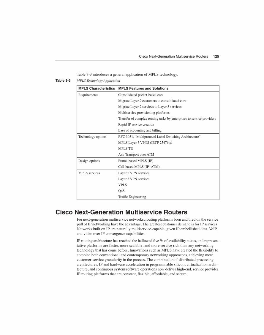
Table 3-3 introduces a general application of MPLS technology.
Cisco Next-Generation Multiservice RoutersFor next-generation multiservice networks, routing platforms born and bred on the service pull of IP networking have the advantage. The greatest customer demand is for IP services. Networks built on IP are naturally multiservice-capable, given IP embellished data, VoIP, and video over IP convergence capabilities.
IP routing architecture has reached the hallowed five 9s of availability status, and represen-tative platforms are faster, more scalable, and more service rich than any networking technology that has come before. Innovations such as MPLS have created the flexibility to combine both conventional and contemporary networking approaches, achieving more customer-service granularity in the process. The combination of distributed processing architectures, IP and hardware acceleration in programmable silicon, virtualization archi-tecture, and continuous system software operations now deliver high-end, service provider IP routing platforms that are constant, flexible, affordable, and secure.
Table 3-3 MPLS Technology Application
MPLS Characteristics MPLS Features and Solutions
Requirements Consolidated packet-based core
Migrate Layer 2 customers to consolidated core
Migrate Layer 2 services to Layer 3 services
Multiservice provisioning platforms
Transfer of complex routing tasks by enterprises to service providers
Rapid IP service creation
Ease of accounting and billing
Technology options RFC 3031, “Multiprotocol Label Switching Architecture”
MPLS Layer 3 VPNS (IETF 2547bis)
MPLS TE
Any Transport over ATM
Design options Frame-based MPLS (IP)
Cell-based MPLS (IP+ATM)
MPLS services Layer 2 VPN services
Layer 3 VPN services
VPLS
QoS
Traffic Engineering
126 Chapter 3: Multiservice Networks
For high-end service provider multiservice routing, the notable products are the Cisco CRS-1 Carrier Routing System, the Cisco IOS XR Software, and the Cisco XR 12000/12000 Series Routers.
Cisco CRS-1 Carrier Routing SystemOnce you turn on the Cisco CRS-1 Carrier Routing System, you might never turn it off. Unlike many routers that have preceded the CRS-1 design, the CRS-1 is scalable and simple, continuous and adaptable, flexible and high performance. None of these individual characteristics of the CRS-1 compromises another, leading to new achievements in nondisruptive scalability, availability, and flexibility of the system. Using the CRS-1 Carrier Routing System, providers can visualize one network with many services and limitless possibilities.
Using a new Cisco IOS XR Software operating system that is also modular and distributed, the CRS-1 is the first carrier IP routing platform that can support thousands of interfaces and millions of IP routes, using a pay-as-you-grow architectural strategy. The CRS-1 blends some of the best of computing, routing, and programmable semiconductor and software architectures for a new, high-end routing system that you can use for decade-plus lifecycles.
Using the CRS-1’s concurrent scalability, availability, and performance, you can use the CRS-1 to consolidate service provider point-of-presence (POP) designs, collapsing core, peering, and aggregation layers inside the covers of one system. Previous routing platforms had limitations in the number of peers, interfaces, or processing cycles, leading to network POP designs that layered functionality based on the performance constraints of the routing platforms. With the CRS-1, these limitations are removed—hardware works in concert with software for extensible convergence of network infrastructure and services. The CRS-1 represents the next-generation IP network core and is the foundation for IP/MPLS provider core consolidation.
CRS-1 Hardware DesignThe CRS-1 hardware system design uses the primary elements of line card and fabric card shelves. Each type of shelf comprises a standard telecommunications rack from a dimensional footprint.
Line Card ShelfLine card shelves support the routing processors, integrated fabric cards and the line card slots, each of which is capable of 40 Gbps performance. Known collectively as a Line Card Chassis, the chassis comes in either an 8-slot version or a 16-slot version.

Cisco Next-Generation Multiservice Routers 127
NOTE Cisco uses shelf as marketing terminology and the term chassis as engineering terminology; both terms are interchangeable.
Two Route Processors are installed per chassis, one for active and one for hot standby. The Route Processors have their own dedicated slots and don’t subtract from the 8 or 16 poten-tial line cards slots of either chassis. Each Line Card Chassis contains up to 8 fabric cards in the rear of the chassis to support the Benes switching fabric for a single shelf system con-figurations. Each line card is composed of rear-facing Interface Modules and front-facing Modular Services Cards connected together via a midplane design. The Line Card Chassis is where route processing, forwarding, and control-plane intelligence of the system resides.
Within each Line Card Chassis are 2 Route Processors, up to 16 Interface Modules, each pairing with 16 Modular Services Cards, and 8 fabric cards. Redundant fan trays, power supplies, and cable management complete the distinctive elements within Line Card Chassis.
Each Route Processor is made up of a symmetrical multiprocessing architecture based on a Dual PowerPC CPU complex with at least 4 GB of DRAM, 2 GB of Flash memory, and a 40 GB micro hard drive. One of the Route Processors operates in active mode with the other in hot standby. The Route Processors, along with system software, can provide non-stop forwarding (NSF) and stateful switchover (SSO) functions without losing packets. Another plus of the CRS-1 architecture is that any Route Processor can control any line card slot, on any Line Card Chassis in a multishelf system. Using features of the Cisco IOS XR Software operating system, Route Processors and line cards can be formed across the sys-tem chassis to create logical routers within the physical CRS-1 overall system. Any time that supplementary processing power is needed, the architecture supports the addition of distributed Route Processors, providing two additional Dual PowerPC CPU complexes with their associated DRAM, Flash, and hard drive.
To create a line card, a combination of Interface Modules and Modular Services Cards are used. The Interface Modules, also referred to as Physical Layer Interface Modules (PLIMs) contain the physical interface ports and hardware interface-specific logic. Interface Modules for the CRS-1 exist for OC-768c/STM-256x, OC-192c/STM-64c, OC-48c/STM-16c, and 10 Gigabit Ethernet. The Interface Modules, installed in the rear card cage of the Line Card Chassis, connect through the midplane to Modular Services Cards in the front card cage of the chassis.
The Cisco Modular Services Cards are made up of a pair of Cisco Silicon Packet Processors (SPPs), each of which is an array of 188 programmable Reduced Instruction Set Computer (RISC) processors. These SPPs are deployed two per Modular Services Card, with one for the input direction and one for output packet processing. The SPP is another key innovation, as the SPP architecture achieves 40 Gbps line rates with multiple services, offering new features through in-service software upgrades to the SPP. The Interface Module and the

128 Chapter 3: Multiservice Networks
Modular Services Card work together as a pair to form a complete line card slot. The Modular Services Card interfaces with the fabric cards, using the switching fabric to reach other line cards or the Route Processor memory.
Fabric ChassisThe Fabric Chassis is used to extend the CRS-1 into a CRS-1 Multishelf System. Up to 8 Fabric Chassis can interconnect as many as 72 Line Card Chassis to create the maximum CRS-1 Multishelf System. The Fabric Chassis is used as a massively scalable stage 2 of the three-stage Benes switching fabric in a multishelf system configuration.
A switching fabric is a switch backplane, and many of the Cisco products use various types of switching fabrics to move packets between ingress interfaces and Route Processor memory and out to egress interfaces. For example, a crossbar fabric is a popular fabric used in many Cisco products, such as the 12000 series and the 7600 series. For hundreds or even thousands of interface ports, a crossbar switching mechanism becomes too expensive and scheduling mechanisms too complex.
Therefore, the CRS-1 implements a three-stage, dynamically self-routed, Benes topology cell-switching fabric. This fabric is a multistage buffered switching fabric that represents the lowest-cost N x N cell-switching matrix that avoids internal blocking. The use of a backpressure mechanism within the fabric limits the use of expensive off-chip buffer memory, instead making use of virtual output queues in front of the input stage. Packets are converted to cells, and these cells are used for balanced load distribution through the switch fabric. The cells are multipath routed between stages 1 and 2 and again between stages 2 and 3 to assist with the overall goal of a nonblocking switching architecture. The cells exit stage 3 into their destination line card slots where the Modular Services Cards reassemble these cells into the proper order, forming properly sequenced packets. The Benes topology switching fabric is implemented in integrated fabric cards for single shelf systems and additionally implemented as standalone Fabric Chassis in a multishelf system configuration. Each standalone Fabric Chassis can contain up to 24 fabric cards for stage 2 operation.
A CRS-1 Single-Shelf system will use integrated fabric cards within the Line Card Chassis that include all three stages within the card. In a CRS-1 Multishelf System, from one to eight CRS-1 Fabric Chassis are used to form stage 2 of the switching fabric, with stage 1 operating on the fabric card of the egress line card shelf and stage 3 operating on the ingress line card shelf across the fabric.
Figure 3-8 shows a conceptual diagram of the CRS-1 switching fabric. Physically, the Cisco CRS-1 fabric is divided into eight planes over which packets are divided into fixed-length cells and then evenly distributed. Within the planes, the three fabric stages—S1, S2, and S3—dynamically route cells to their destination slots, where the Modular Services Cards reassemble cells in the proper order to form properly sequenced packets.

Cisco Next-Generation Multiservice Routers 129
Figure 3-8 One Plane of the Eight-Plane Cisco CRS-1 Switching Fabric
Source: Cisco Systems, Inc.
Together the Route Processors, fabric cards, Interface Modules, and Modular Services Cards work with the IOS XR operating system to create a routing architecture that is scalable from 640 Gbps to 92 Tbps (terabits per second) of performance. These capacities are accomplished through various configurations of a CRS-1 Multishelf System or a CRS-1 Single-Shelf System. The overall CRS-1 architectural design is conceptualized in Figure 3-9.
Cisco CRS-1 Multishelf SystemThe Cisco CRS-1 Multishelf Systems are constructed using a combination of Line Card Chassis and Fabric Chassis. Up to 72 Line Card Chassis can be interconnected with 8 Fabric Chassis to create a multishelf system with as many as 1,152 line card slots, each capable of 40 Gbps, yielding approximately 92 Tbps (full duplex) of aggregate performance capacity. Cisco CRS-1 Multishelf Systems can start with as few as 2 Line Card Chassis and 1 Fabric Chassis and grow as demand occurs.
S1 S2 S3
S1 S2 S3

130 Chapter 3: Multiservice Networks
Figure 3-9 Cisco CRS-1 Hardware Architecture
Source: Cisco Systems, Inc.
Within a multishelf system, any Route Processor can control any line card on any Line Card Chassis in the system. For example, a Route Processor in Line Card Chassis number 1 can be configured to control a line card in Line Card Chassis number 72 using the Fabric Chassis as an internal connectivity path. Route Processors and distributed Route Processors are responsible for distributing control plane functions and processing for separation, performance, or logical routing needs.
Using a Cisco CRS-1 Multishelf System, providers can achieve the following configurations:
• 2 to 72 Line Card Chassis
• 1 to 8 Fabric Chassis
• Switching capacity from 640 Gbps to 92 Tbps (full duplex)
Line Card
Line Card
Line Card
ModulamService Card
CiscoSPP
CiscoSPP
InterfaceModule
MD
Pla
ne
S1
S1
S2
S2
S3
S3
S3
S3
Multi-StageSwitch Fabric
RouteProcessor
RouteProcessor
RouteProcessor

Cisco Next-Generation Multiservice Routers 131
• Support for up to 1,152 line cards at 40 Gbps each
— 1,152 OC-768c/STM-256c POS ports
— 4,608 OC-192c/STM-64c POS/DPT ports
— 9,216 10 Gigabit Ethernet ports
— 18,432 OC-48c/STM-16c POS/DPT ports
Cisco CRS-1 16-Slot Single-Shelf SystemThe CRS-1 Single-Shelf Systems come as either a 16-slot or an 8-slot Line Card Chassis. Single-shelf systems use integrated Switch Fabric Cards (SFCs), installed in the rear card cage of the Line Card Chassis rather than using a standalone Fabric Chassis. In a single-shelf system configuration, the integrated SFCs perform all three stages of the Benes topology switching fabric operation. Using a Cisco CRS-1 16-Slot Single-Shelf System, providers can achieve the following configurations:
• 16-slot Line Card Chassis with integrated fabric cards
• Switching capacity to 1.28 Tbps (full duplex)
• Support for up to 16 line cards at 40 Gbps each
— 16 OC-768c/STM-256c POS ports
— 64 OC-192c/STM-64c POS/DPT ports
— 128 10 Gigabit Ethernet ports
— 256 OC-48c/STM-16c POS/DPT ports
Cisco CRS-1 8-Slot Single-Shelf SystemThe CRS-1 Single-Shelf Systems also come in an 8-slot Line Card Chassis. The 8-slot Line Card Chassis is one half as tall as a 16-slot Line Card Chassis. As previously mentioned, single-shelf systems use the integrated SFCs, installed in the rear card cage of the Line Card Chassis, performing all three stages of the Benes topology switching fabric operation. Using a Cisco CRS-1 8-Slot Single-Shelf System, providers can achieve the following configurations:
• 8-slot Line Card Chassis with integrated fabric cards
• Switching capacity to 640 Gbps (full duplex)
• Support for up to 8 line cards at 40 Gbps each
— 8 OC-768c/STM-256c POS ports
— 32 OC-192c/STM-64c POS/DPT ports
— 64 10 Gigabit Ethernet ports
— 128 OC-48c/STM-16c POS/DPT ports

132 Chapter 3: Multiservice Networks
Cisco IOS XR SoftwareThe Cisco IOS XR Software is likely to be one of the most important technology innovations of this decade. Benefiting from over 20 years of IOS development and experience, the Cisco IOS XR answers the following questions:
• “Why can’t a router platform be divided into separate physical and logical partitions as the computer industry has done with mainframes for many years?” Now it can.
• When presented with the question, “Why can’t a router’s control plane be separated to individually manage, restart, and upgrade software images without risk to other partitions?” With IOS XR, now you can.
• When the inquiry is made as to “when will a router support five nines of reliability?” With IOS XR in use, now it does.
IOS XR answers these questions and more with massive scalability; a high-performance, distributed processing, multi-CPU optimized architecture; and continuous system opera-tion. With IOS XR in a CRS-1 Multishelf System, distributed processing intelligence can take full advantage of hardware interface densities and symmetric multiprocessing power, scaling up to 92 Tbps per multishelf system. IOS XR is built on a QNX microkernel operating system with memory protection that places strict logical boundaries around sub-systems to ensure independence, isolation, and optimization. Only the essential operating functions reside in the kernel to strengthen this key element of the overall software system.
Through the ability to distribute processes and subsystems anywhere across CRS-1 hardware resources, the IOS XR can dedicate processing, protected memory, and control functions to these resources—creating not only logical routers, but resource-allocated physical routers as well. This leads to the ability to partition operations such that a production routing system and a development routing system can reside on the same physical system. This can become an opportunity to market to a sophisticated customer both a production networking service for mission-critical applications, as well as a development networking partition where new features can be developed and tested without the consequences of impacting mission-critical applications. Or a provider can run multiple MPLS administrative domains on the same physical system, each with attributes and software characterized to a leading edge, edge, or lagging edge type of network service, applying more granularity to customer risk and choice. The separation architecture of IOS XR blended with hardware platforms provides flexibility in IP network design for providers.
With IOS XR, multiple partitions can mean multiple software versions running on the same physical system chassis. IOS software levels are distributed in a modular fashion, allowing for software patches and bug fixes in one partition without affecting others. This takes on an in-service upgrade approach, as each partition process can be restarted without affecting the other running systems and their respective routing topology.

Cisco Next-Generation Multiservice Routers 133
In today’s networks, security and reliability are mutual. Perhaps one of the greatest benefits of the IOS XR’s isolatable architecture is the ability to resist malicious attacks, such as TCP/IP-based denial of service and distributed denial of service threats. Even if a TCP/IP subsystem were to be compromised, a compromised TCP subsystem would run outside of the IOS XR system kernel, so the IOS XR system kernel and other protected subsystem processes would continue to operate. The Cisco IOS XR Software architecture is concep-tualized in Figure 3-10.
Figure 3-10 Cisco IOS XR Software Architecture
Source: Cisco Systems, Inc.
The Cisco IOS XR Software assists with making the latest high-end routing systems more scalable, flexible, reliable, and secure. The Cisco IOS XR Software is perhaps the prime catalyst for next-generation IP/MPLS networks that can now operate on a worldwide scale. For a full listing of features and functions, examine the various Cisco CRS-1 and IOS XR information found at http://www.cisco.com/go/crs.
Cisco XR 12000/12000 Series RoutersThe Cisco XR 12000 Series Routers are so named because they combine the innovative features of the Cisco IOS XR Software with the superior heritage of the Cisco 12000 Series routing platforms. The Cisco XR 12000/12000 Series Routers are optimally positioned for
BGP IS-IS RIP
OSPF PIM IGMP
QoS FIB LPTS
ACL PRI L2Drivers
CLI XML Alarm
Net-Flow SNMP SSH
Distributed OS Infrastructure
Control Plane Data Plane Management Plane
BGP
Speaker
Route Selection
Process Manager

134 Chapter 3: Multiservice Networks
the next-generation core and edge of provider networks, with a strength in multiservice edge consolidation. The XR 12000s are optimized to run the Cisco IOS XR Software, while the 12000s are the original 12000 series running the Cisco IOS software.
Using the Cisco IOS XR Software with the distributed architecture of the XR 12000, the XR 12000 routers achieve both logical and physical routing functionality that can operate independently within a single XR 12000 chassis. A private MPLS VPN service could be completely isolated from a public Internet service for security but also operationally separate. For example, an anomaly affecting the public Internet service might result in a need to restart that service within the router; however, this action wouldn’t affect the private MPLS VPN service running as a separate process. There are four primary elements that comprise the XR 12000 architecture:
• General Route Processor
• Switch fabric
• Intelligent line cards
• Operating software
XR 12000/12000 ArchitectureAll generic routers use a general Route Processor to provide control plane, data plane, and management plane functions. As line speeds and densities increase, this Route Processor must be able to keep up with the data forwarding rate, while also maintaining control and management functions simultaneously. At higher line rates, centralized processor architectures encounter timing sensitivities that put constraints on parallel feature processing. Distributed processing architectures, as in the XR 12000/12000 series, remove these constraints and leverage multiprocessing for aggregate switching performance gains. The XR 12000/12000 routers are optioned with a premium routing processor known as the Performance Route Processor P2 (PRP-2). The PRP-2 is capable of more than one million route prefixes and 256,000 multicast groups. It assists the 12000 routers with reaching up to 1.2 Tbps of aggregate switching performance in conjunction with an appropriate quantity and speed of the intelligent line cards.
In addition to the Cisco IOS XR Software benefits, the distribution of multiple processors within the XR 12000 chassis allows for an extension and separation of the control plane across multiple service instances. This provides control and management plane independence, helping facilitate logical and physical independence. These distributed processors are manifested in IP Services Engines (ISEs) with a particular ISE personalization representing the central intelligence of each line card.
ISEs are Layer 3-forwarding, CEF-enabled packet processors built with programmable, application-specific integrated circuits (ASICs) and optimized memory matrices. The primary benefit to the ISE technology is the ability to run parallel, IP feature processing at the network edge—at line rate. The programmability of the ISEs is key to investment

Cisco Next-Generation Multiservice Routers 135
protection, as new features can be added without a hardware upgrade. ISEs are architected for 2.5 Gbps, 10 Gbps, and 40 Gbps operation and are often optimized toward core or edge functions. The ISEs have been proceeding through various technology enhancements over the past several years and are classified relative to functionality. ISE functional classifications, such as the following, are by engine type:
• ISE engine 0—Known internally as the OC-12/BMA, this original ISE engine 0 uses an R5K CPU. Most features are implemented in software. An example of an ISE engine 0 is the 4-port OC-3 ATM line card. QoS features are rather limited.
• ISE engine 1—Known internally as the Salsa/BMA48, this engine was improved using a new ASIC (Salsa), allowing IP lookup to be performed in hardware. An example of an ISE engine 1 is the 2-port OC-12 Dynamic Packet Transport (DPT) line card. QoS features are rather limited.
• ISE engine 2—Known internally as the Perf48, this engine added new ASICs to perform hardware lookup for IP/MPLS switching. On-card packet memory was increased to 256 MB or 512 MB. New hardware-based class of service features were added, such as weighted random early detection (WRED) and Modified Deficit Round Robin (MDRR). An example of an ISE engine 2 is the 3-port Gigabit Ethernet line card.
• ISE engine 3—Internally referred to as the Edge engine, engine 3 is a completely rearchitected Layer 3 engine. Engine 3 accommodates an OC-48 worth of bandwidth and integrates additional ASICs to improve QoS and access control list (ACL) features that can be performed at line rate. An example of an ISE engine 3 is the 1-port OC-48 POS ISE line card. There is also an engine 3 version of the 4-port OC3 ATM card mentioned earlier.
• ISE engine 4—Referred to as the Backbone 192 engine, this engine is optimized and accelerated to support an OC-192 line rate. An example of an ISE engine 4 is the 1-port OC-192 POS line card.
• ISE engine 5—Optimized for 10 Gbps line rates with full feature sets including multicast replication. An example of an ISE engine 5 is the SIP-600 SPA Interface Processor-600 line card.
Depending on an ISE’s functional legacy, an ISE might not be supported by new features in Cisco IOS software or the Cisco IOS XR Software. It is always wise to consult Cisco support tools to determine hardware platform, ISE engine type, and software feature compatibility when designing with these components.
The XR 12000/12000 multigigabit switch fabric works in combination with a passive chassis backplane, interconnecting all router components within an XR 12000/12000 router chassis. The active switching fabric is resident on pluggable cards known as SFCs and clock scheduler cards (CSCs), and these SFCs/CSCs are installed in a lower card shelf that interconnects with the XR 12000 backplane. This allows the SFCs/CSCs to be field upgraded easily. For example, changing a router to support 40 Gbps per line card slot from

136 Chapter 3: Multiservice Networks
a 10 Gbps per line card slot can be accomplished through a replacement of the SFCs/CSCs with appropriate SFCs/CSCs that can clock and switch 40 Gbps-enabled ISE line cards and the PRP-2. This allows a XR 12000/12000 router to grow to as much as 1.28 Tbps of aggregate switching capacity. Another performance-enhancing feature of the XR 12000 switch fabric is that any IP multicast packet replication (for example, IP video) is now performed by the switch fabric itself, rather than burdening the general Route Processor (PRP-2).
The Cisco XR 12000 Series Routers are capable of running the Cisco IOS XR Software previously described. This software extends continuous system operation, performance scalability, and logical and physical virtualization features to the XR 12000 series routing platforms.
Cisco XR 12000/12000 CapacitiesThe Cisco XR 12000/12000 Series Routers comprise a scalable range of capacity from 30 Gbps to 1,280 Gbps (1.28 Tbps). Multiservice routers are commonly categorized by card slot quantity, throughput capacity per slot, and aggregate switching fabric capacity (full duplex or bidirectional). You can determine these three items via the Cisco model number without referencing any documentation. The model number convention defines the first two digits (12XXX) as the 12000 series family of routers. An XR-capable chassis will be prefixed with an XR (XR-12XXX).
The third digit of the 12000 model number represents the full-duplex (FDX) line rate capacity per card slot where XX0XX equals 2.5 Gbps (which is 5 Gbps FDX), XX4XX equals 10 Gbps (20 Gbps FDX), and XX8XX equals 40 Gbps (80 Gbps FDX).
The fourth and fifth digits of the 12000 model number convention define the total number of chassis card slots, where 12X04 equals four card slots, 12X06 equals six card slots, 12X10 equals 10 card slots, and 12X16 equals a 16-card slot router chassis.
To determine the gross-effective aggregate switching capacity of a particular model, you can multiply the line rate per card slot by the number of card slots, but this is where it can get confusing. Vendor literature often discusses line rate capabilities of the vendor’s products using industry-familiar line rates of 2.5 Gbps (OC-48/STM-12), 10 Gbps (OC-192/STM-64), and 40 Gbps (OC-768/STM-256) services. On closer introspection, that line rate is used in a total aggregate capacity calculation for the router, but the line rate is doubled to reflect a full-duplex mode of operation. Often forgotten is that a 10 Gbps line rate is capable of that speed bidirectionally, both in the transmit and receive directions simultaneously. The calculation of theoretical total capacity becomes the full-duplex line rate (for example, 10 Gbps becomes 20 Gbps FDX) times the number of card slots.
Continuing with the Cisco model number convention, you can examine the third digit to determine the full-duplex line rate per card slot (for example, 4 = 10 Gbps half duplex [HDX] = 20 Gbps FDX) and multiply times the number of total card slots indicated by the

Cisco Next-Generation Multiservice Routers 137
fourth and fifth digits of the model number. A model with the number 12410 would calculate as 20 Gbps x 10 cards = 200 Gbps of total aggregate switching capacity for the 12410 platform. A model 12816 would calculate to 80 Gbps x 16 slots = 1,280 Gbps or 1.28 Tbps. This is gross-effective switching capacity, and the actual net-effective capacity will depend on the number of general-purpose processors (for example, PRP-2) configured for the system, as these subtract from the available card slots in most of the systems.
Figure 3-11 shows the relative positioning of the Cisco XR 12000/12000 Series Routers based on gross-effective capacities. As the figure shows, most models have a growth path for executing a pay-as-you-grow strategy.
Figure 3-11 Cisco XR 12000/12000 Series Router Capacities
The XR 12000/12000 series router product line includes additional features worthy of mention. The routers use the Cisco I-Flex design, which is implemented as intelligent, programmable interface processors with modular port adapters. This design combines both shared port adapters (SPAs) with SPA interface processors (SIPs) to improve line card slot economics and service density. The SIPs use the IP Services Engine (ISE) technology and are packaged into a SIP-400 or SIP-600 line card for the 12000 platform. The SIP-600 supports 10 Gbps per slot with two single- or double-height SPAs, and the SIP-400 supports 2.5 Gbps per slot and up to four single-height SPAs. A number of different SPAs are available to connect high-speed interfaces. The combination of the SPAs/SIPs creates interface flexibility, portability, and density for the XR 12000/12000 router platforms.
30 50
12016
12406
12810 12816
12410 12416
124041200612010
80 120 200 320 640 800 1280(1.28 Tbps)
2.5 G
10 G
40 G
Cisco XR 12000 and 12000 Series Routers
Aggregate Switching Capacity (Gbps)
Line
Rat
e P
er C
ard
Slo
t (G
bps)

138 Chapter 3: Multiservice Networks
The platforms have enhanced fabrics that now support Building Integrated Timing Source (BITS) and single-router Automatic Protection Switching (SR APS). BITS allows for a centralized timing distribution for multiservice edge applications, particularly where the 12000 is used to aggregate traffic from ATM access networks. These ATM networks have relied on BITS, and the feature is essential to allow migration of ATM access networks onto XR 12000/12000-based IP/MPLS core networks. The SR APS feature enables true APS through the 12000 system platforms. Adding APS to the fabric and the support of a backpressure mechanism in the fabric scheduler eliminates timing slips when switching between active and standby cards, leveraging the fabric mirroring function and locking the timing to BITS. The fabric’s backpressure support keeps the routers from dropping packets if an active card is removed.
Multiservice Core and Edge SwitchingNetworking traffic continues to accelerate at the metro edge and aggregate into the metro core, from large enterprises driving Ethernet requirements into metropolitan area networks (MANs) to rising waves of broadband from small and medium businesses and consumers. In fact, the Ethernet opportunity within the service provider space is wide open, and providers of all types are counting on Ethernet services as a large part of their portfolio growth. While there is a demand shift from circuit to packet traffic within the MAN, the vast installation base of SONET/SDH service functionality precludes a forklift upgrade of metropolitan provider technology, instead requiring an evolutionary migration path to packet-based services from a SONET/SDH heritage.
Multiservice Provisioning Platforms (MSPPs) combine the functions and services of different network elements into a single device. For a few more years, voice traffic is predicted to remain the cash cow of provider revenues, making time division multiplexing (TDM) switching support an important requirement. The MSPP market is defined as new-generation provider equipment with SONET/SDH add/drop multiplexer (ADM) functionality, TDM and packet functionality, particularly Ethernet, and is deployed at the metro multiservice edge or core.
Multiservice Switching Platforms (MSSPs) are optimized for metropolitan core aggrega-tion requirements, typically consolidating multiple discreet SONET ADMs and broadband digital access cross-connect systems (DACSs), while providing core switching services for multiple MSPP deployments.
Eliminating platforms, no matter how reliable, reduces the single points of failure in the overall network architecture. MSPPs and MSSPs integrate multiple device functions to allow consolidation of platforms while introducing new technology for services innovation.
MSPPs and MSSPs entered the market at the beginning of a long telecom winter in 2000. However, their inherent value proposition has weathered the fiscal storms and frozen budgets, finding favor first with emerging network providers and then moving into the
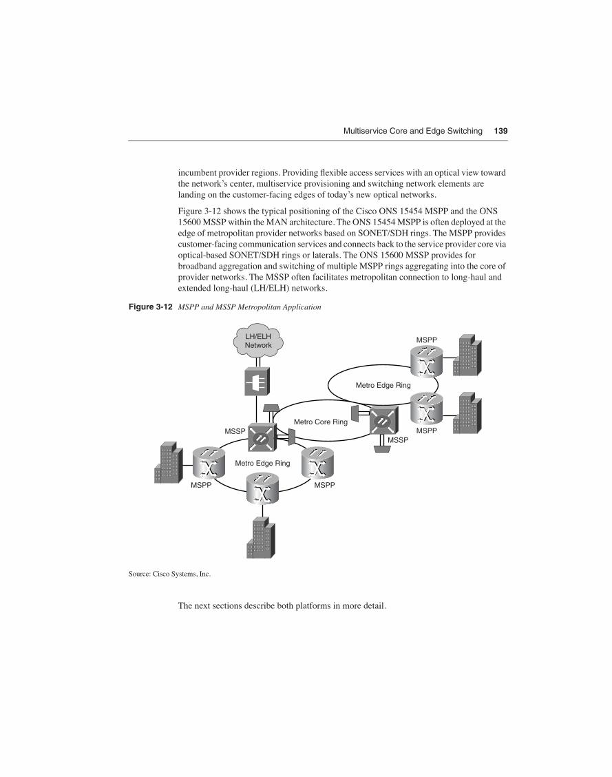
Multiservice Core and Edge Switching 139
incumbent provider regions. Providing flexible access services with an optical view toward the network’s center, multiservice provisioning and switching network elements are landing on the customer-facing edges of today’s new optical networks.
Figure 3-12 shows the typical positioning of the Cisco ONS 15454 MSPP and the ONS 15600 MSSP within the MAN architecture. The ONS 15454 MSPP is often deployed at the edge of metropolitan provider networks based on SONET/SDH rings. The MSPP provides customer-facing communication services and connects back to the service provider core via optical-based SONET/SDH rings or laterals. The ONS 15600 MSSP provides for broadband aggregation and switching of multiple MSPP rings aggregating into the core of provider networks. The MSSP often facilitates metropolitan connection to long-haul and extended long-haul (LH/ELH) networks.
Figure 3-12 MSPP and MSSP Metropolitan Application
Source: Cisco Systems, Inc.
The next sections describe both platforms in more detail.
Metro Core Ring
MSPP
MSPP
MSPP
MSSP
MSPP
MSSP
Metro Edge Ring
Metro Edge Ring
LH/ELHNetwork

140 Chapter 3: Multiservice Networks
Multiservice Provisioning Platform (MSPP)The market for MSPPs emerged in 2000, starting the century strong with network edge technology turnover and service positioning. This market was seeded by technology pioneered by up-start Cerent, which was acquired by Cisco in 1999. One year later, the MSPP market gathered $1 billion in revenue on a worldwide basis.
The primary appeal for MSPPs is to consolidate long-established SONET/SDH ADMs in the multiservice metro, while incorporating Layer 2 and new Layer 3 IP capabilities with packet interfaces for Ethernet, Fast Ethernet, and Gigabit Ethernet opportunities. Many MSPPs contain additional support for multiservice interfaces and dense wavelength divi-sion multiplexing (DWDM) to optimize the use of high-value metropolitan optical fiber. Deployed as a springboard for the rapid provisioning of multiple services, the intrinsic value of these new-generation platforms is to build a bridge from circuit-based transport to packet-based services. MSPPs help providers to execute that strategy while maintaining established services with TDM switching support and SONET/SDH capabilities.
Entering the market near the end of many legacy SONET/SDH ADM depreciation schedules, the MSPPs inherit a sizable portion of their justification from reduced power, space, and maintenance requirements. In doing so, MSPPs help with continued optimization of operating budgets while representing strategic capital investments for new high-value service opportunity.
It is difficult to discuss SONET/SDH without a reference of the bandwidth speeds and terminology used by these worldwide standards. Table 3-4 shows a comparison of SONET/SDH transmission rates.
Table 3-4 Comparison of SONET/SDH Transmission Rates
Digital Hierarchy for United States SONET (GR.253)
Digital Hierarchy for European SDH (G.691)
Line Rate (Mbps)
Payload Rate (Mbps)
SONET Electrical Signal
SONET Optical Carrier (OC) Transport Level
SDHEquivalent Transport
51.84 50.112 STS-1 OC-1 STM-0
155.520 150.336 STS-3 OC-3 STM-1
622.080 601.344 STS-12 OC-12 STM-4
2,488.32 2405.376 STS-48 OC-48 STM-16
9,953.28 (10 Gbps)
9621.504 STS-192 OC-192 STM-64
39,813.12 (40 Gbps)
38486.016 STS-768 OC-768 STM-256
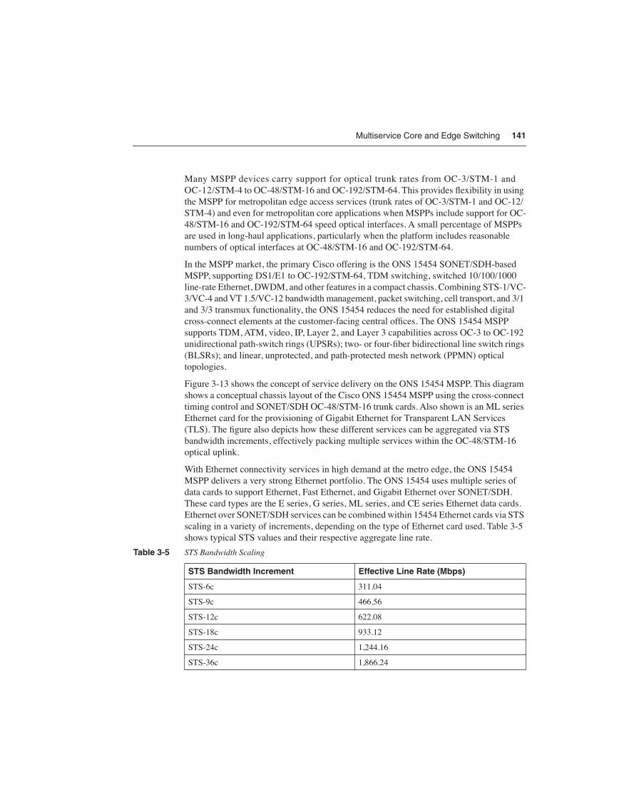
Multiservice Core and Edge Switching 141
Many MSPP devices carry support for optical trunk rates from OC-3/STM-1 and OC-12/STM-4 to OC-48/STM-16 and OC-192/STM-64. This provides flexibility in using the MSPP for metropolitan edge access services (trunk rates of OC-3/STM-1 and OC-12/STM-4) and even for metropolitan core applications when MSPPs include support for OC-48/STM-16 and OC-192/STM-64 speed optical interfaces. A small percentage of MSPPs are used in long-haul applications, particularly when the platform includes reasonable numbers of optical interfaces at OC-48/STM-16 and OC-192/STM-64.
In the MSPP market, the primary Cisco offering is the ONS 15454 SONET/SDH-based MSPP, supporting DS1/E1 to OC-192/STM-64, TDM switching, switched 10/100/1000 line-rate Ethernet, DWDM, and other features in a compact chassis. Combining STS-1/VC-3/VC-4 and VT 1.5/VC-12 bandwidth management, packet switching, cell transport, and 3/1 and 3/3 transmux functionality, the ONS 15454 reduces the need for established digital cross-connect elements at the customer-facing central offices. The ONS 15454 MSPP supports TDM, ATM, video, IP, Layer 2, and Layer 3 capabilities across OC-3 to OC-192 unidirectional path-switch rings (UPSRs); two- or four-fiber bidirectional line switch rings (BLSRs); and linear, unprotected, and path-protected mesh network (PPMN) optical topologies.
Figure 3-13 shows the concept of service delivery on the ONS 15454 MSPP. This diagram shows a conceptual chassis layout of the Cisco ONS 15454 MSPP using the cross-connect timing control and SONET/SDH OC-48/STM-16 trunk cards. Also shown is an ML series Ethernet card for the provisioning of Gigabit Ethernet for Transparent LAN Services (TLS). The figure also depicts how these different services can be aggregated via STS bandwidth increments, effectively packing multiple services within the OC-48/STM-16 optical uplink.
With Ethernet connectivity services in high demand at the metro edge, the ONS 15454 MSPP delivers a very strong Ethernet portfolio. The ONS 15454 uses multiple series of data cards to support Ethernet, Fast Ethernet, and Gigabit Ethernet over SONET/SDH. These card types are the E series, G series, ML series, and CE series Ethernet data cards. Ethernet over SONET/SDH services can be combined within 15454 Ethernet cards via STS scaling in a variety of increments, depending on the type of Ethernet card used. Table 3-5 shows typical STS values and their respective aggregate line rate.
Table 3-5 STS Bandwidth Scaling
STS Bandwidth Increment Effective Line Rate (Mbps)
STS-6c 311.04
STS-9c 466.56
STS-12c 622.08
STS-18c 933.12
STS-24c 1,244.16
STS-36c 1,866.24

142 Chapter 3: Multiservice Networks
Figure 3-13 Service Delivery on the Cisco ONS 15454 MSPP
Source: Cisco Systems, Inc.
Cisco ONS 15454 E Series Ethernet Data CardThe E series data cards support 2.4 Gbps of switching access to the TDM backplane, interfacing at STS rates up to STS-12. These cards support 10 Mbps Ethernet, 100 Mbps Fast Ethernet, and 1000 Mbps Gigabit Ethernet (limited to 622 Mbps) using STS bandwidth scaling at increments of STS-1c, STS-3c, STS-6c, and STS-12c. These cards are useful for setting up point-to-point Ethernet private lines, which don’t need Spanning Tree Protocol (STP) support.
Cisco ONS 15454 G Series Ethernet Data CardThe G series data cards are higher-density Gigabit Ethernet cards, supporting access to the ONS 15454’s TDM backplane at rates up to STS-48/VC-x-y. STS/VC bandwidth scaling is available for the real concatenation (RCAT) standard in selectable increments of STS-1, STS-3c, STS-12c, and STS-24c. The extended concatenation (ECAT) standard is supported with increments of STS-6c, STS-9c, and STS-24c. The G series cards yield higher perfor-mance with aggregate access rates of four times the E series cards. All Ethernet frames are simply mapped into SONET/SDH payloads, so there are fewer design constraints and
OC-48BandwithCapacity
STS-24 forLine RateGigabit
STS-12 for Ethernet SLAs
OC-3 Service
TD OC
-48
OC
-48
TC
C2
TC
C2
XC
-10G
XC
-10G
TLS Internet Access
Catalyst
ONS 15454 with ML-SeriesNetwork-Side
Representation
• Using SONET Infrastructure
• <50 ms SONET Recovery
• SP Management with TL1, OSMINE
• Rate Limiting Per-Port/Service Basis
• QoS/CoS Through Traffic Classification
• Security Benefits
PrivateLineGigabitEthernetService

Multiservice Core and Edge Switching 143
ultra-low latency. The cards also support Gigabit Etherchannel or the 802.3 ad link aggre-gation standard, so that multigigabit Ethernet links can be created to scale capacity and link redundancy. The G series cards are targeted at the point-to-point Ethernet private line mar-ket, where speeds beyond 1 Gbps are desired services.
Cisco ONS 15454 ML Series Ethernet Data CardWith the ML series data cards, you can create any point-to-point or multipoint Ethernet service using the Layer 2 or Layer 3 control planes or via the software provisioning tools. These cards are used primarily for Fast Ethernet and Gigabit Ethernet support. Multiple levels of priority are available for class of service awareness, as is the ability to guarantee sustained and peak bandwidths.
These cards access the TDM backplane at an aggregate level of 2.4 Gbps. The ML series Ethernet ports can be software provisioned from 50 Mbps to the port’s full line rate in STS-1, STS-3c, STS-6c, STS-9c, STS-12c, and STS-24c increments. Bandwidth guarantees can be established down to 1 Mbps.
ML series cards take advantage of features within Cisco IOS software, sharing a common code base with Cisco enterprise routers. The ML series includes two virtual Packet over SONET/SDH ports, which support Generic Framing Protocol (GFP) and virtual concatenation (VCAT) with software-based Link Capacity Adjustment Scheme (SW-LCAS). EoMPLS is supported as a Layer 2 bridging function. Virtual LANs (VLANs) can be created using the IEEE 802.1Q VLAN encapsulation standard, which can tag up to 4096 separate VLANs and additionally supports the IEEE 802.1Q tunneling standard (Q-in-Q) and Layer 2 protocol tunneling. Layer 2 Ethernet VPNs are best supported via the 802.1Q tunneling standard using this double-tagging hierarchy to preserve provider VLANs. It does this by tunneling all of the customer’s 802.1Q tagged VLANs within a single provider 802.1Q VLAN instance. For Layer 2 VPN delivery across multiple SONET/SDH rings, a combination of IEEE 802.1Q tunneling in the access layer and EoMPLS across the core is a recommended design practice. All of these features allow for a strong Ethernet rate shaping functionality at the edge with highly reliable SONET/SDH protection.
Cisco ONS 15454 CE Series Ethernet Data CardThe CE series card is named for “Carrier Ethernet.” This card is designed for optimum delivery of carrier-based, private-line Ethernet services, leveraging enhanced capabili-ties over SONET/SDH MSPP networks. Specifically, this card supports eight ports of 10/100BASE-T RJ45 Ethernet. What is key is that the CE series card supports Packet over SONET/SDH virtual interfaces, supports GFP, and can use high-order VCAT and LCAS for optimum bandwidth over SONET/SDH efficiency and in-service bandwidth capacity adjustments. Typical Ethernet features and 802.1p Type of Service (ToS) is supported.

144 Chapter 3: Multiservice Networks
The card has a maximum aggregate capacity of 600 Mbps, yielding a low oversubscription ratio if all eight ports are provisioned for full 100BASE-T operation. Each port can be configured from 1.5 Mbps to 100 Mbps, leveraging the capabilities of low-order and high-order VCAT. Each port forms a virtual concatenation group (VCG) using contiguous concatenation (CCAT) or VCAT, and port traffic from these eight Ethernet interfaces is mapped into the virtual Packet over SONET (PoS) interfaces via either GFP or High-Level Data Link Control (HDLC) framing. Each port forms a one-to-one relationship, as each port-based VCG is identifiable within the resulting SONET/SDH circuit that is created upstream of the ONS 15454 MSPP. Since each VCG is identifiable, LCAS can then be used to dynamically adjust individual port bandwidth capacity on-the-fly, in real time. A customer can order 1.5 Mbps Ethernet service and then grow to 100 Mbps capacity in appropriate increments on an in-service basis. This facilitiates a key differentiator for providers looking to craft dynamic provisioning of Ethernet-based services.
Multiservice Switching Platforms (MSSP)The MSSP is a natural follow-on to the success of the MSPP. The MSSP is a new-generation SONET/SDH, metro-optimized switching platform that switches higher-bandwidth traffic from MSPP edge to edge or from edge to core, allowing metro networks to scale efficiently.
When you consider that edge MSPPs increase bandwidth aggregation from typical OC-3/STM-1 and OC-12/STM-4 bulk traffic to new levels of OC-48/STM-16 and OC-192/STM-64, the bandwidth bottleneck can move from the metropolitan edge to the metropolitan core. The increased bandwidth shifts the management focus from DS0s and T1s to SONET STS or SDH VC-4 levels. As this bandwidth is delivered toward the network core, efficient scaling is needed, particularly for large metropolitan areas. The MSSP serves that need by aggregating high-bandwidth MSPP edge rings onto the provider’s interoffice ring. Its high-density design and small footprint positions the MSSP device to replace multiple, often stacked, high-density SONET ADMs and broadband digital cross-connects (BBDXCs) that are used to groom access rings to interoffice rings. This allows a reduction in network element platforms and single points of failure within central offices of the MAN architecture.
Figure 3-14 shows this concept of not only consolidating equipment and functionality within the central office but the added benefit of Layer 2 switching capability using the Cisco MSSP and MSPP architecture.

Multiservice Core and Edge Switching 145
Figure 3-14 SONET/SDH Network Element Consolidation Using Cisco MSSP and MSPP
Source: Cisco Systems, Inc.
The MSSP is a true multiservice platform that leverages a provider’s investment in SONET or SDH optical infrastructure. Supporting a wide variety of network topologies makes the MSSP adaptable to any optical architecture. In SONET networks, the Cisco MSSP supports UPSRs, as stated by Telcordia’s GR-1400, and two-fiber and four-fiber BLSRs and 1+1 automatic protection switching (APS), as stated by Telcordia’s GR-1230. In SDH networks, the Cisco MSSP supports subnetwork connection protection (SNCP) rings, multiplex section shared protection ring (MS-SPRing), and SDH multiplex section protection (MSP) topologies as defined by International Telecommunication Union (ITU) recommendations. Additionally, the Cisco MSSP supports the PPMN. A PPMN topology allows for optical spans to be upgraded incrementally to higher bandwidth as traffic requirements dictate, rather than upgrading a complete UPSR span all at once with traditional topology designs.
Leveraging the MSSP’s integrated DWDM capability keeps the number of discrete network elements small. DWDM is a critical requirement in the MAN as new lambda-based services become necessary to address the number of discrete service requirements of customers, while also extending the capacity and life of a provider’s metropolitan fiber plant.
The MSSP also incorporates MSPP functions, which is necessary to perform the following tasks:
• Connect and switch TDM voice to Class 5 TDM voice switches
• Switch ATM cells to ATM switches
• Switch packets to IP routers
ADMs
SonetADMs
OC-48/OC-192Rings
OC-48/OC-192Rings
OC-48/OC-192
C.O.
TDM SwitchingOnly
BBDXC
Typical BBDXC Application MSSP + MSPP Solution
C.O.
TDM andL2 Switching
MSSP
MSPP

146 Chapter 3: Multiservice Networks
All of these devices are typically found in a provider’s service point of presence (POP). By including support for Gigabit Ethernet in the MSSP, the platform can perform MSPP functions at this service POP level, reducing or eliminating the need for a discrete MSPP platform in that portion of the provider’s network. This capability also strengthens integration between MSPP-to-MSSP-to-MSPP services, as MSPP edge traffic passes through the metro core, often destined for other edge MSPPs.
The lead Cisco product in the MSSP market is called the ONS 15600 MSSP. The ONS 15600 is optimized for metro MSPP aggregation deployments and typically displaces established SONET ADMs and BBDXCs at service POPs. It also competes well against many of the next-generation optical cross-connects that are more optimized for the long-haul core environment rather than the metro and also lack the SONET MSPP integration and long-reach optics capabilities required in the metro.
The heart of the ONS 15600 is a fully redundant 320 Gbps switch fabric with a three-stage pseudo-CLOS architecture in a 25x23.6x23.6 inch shelf. Line card slots are architected for 160 Gbps access to the switch fabric, and current line card densities use 25 percent of that capacity at up to 40 Gbps per line card with less than 25 millisecond protection switching. The use of the Any Service Any Port (ASAP) line card allows the ONS 15600 to be very flexible in supporting SONET/SDH optical interfaces of OC-3/STM-1, OC-12/STM-4, OC-48/STM-16, and Gigabit Ethernet, including the use of multirate small form-factor pluggable (SFP) optics that can be in-service software provisioned to change a selected port’s optical interface from OC-3/STM-1 to OC-12/STM-4, OC-48/STM-16, or Gigabit Ethernet.
The 160 Gbps-per-slot architecture positions the ONS 15600 for upgrades to OC-768/STM-256 capabilities and integrates support beyond Gigabit Ethernet to 10 Gigabit Ethernet and DWDM interfaces.
The ONS 15600 uses industry-leading port densities per line card accommodating up to
• 128 OC-3/STM-1s (using an ASAP line card)
• 128 OC-12/STM-4s (using an ASAP line card
• 128 OC-48/STM-16s (using an ASAP line card)
• 32 OC-192/STM-64s
• 128 Gigabit Ethernet (using an ASAP line card) per 15600, depending on the line card mixture
Three ONS 15600 shelves can be mounted in a standard seven-foot rack, a typical defacto measure of port and switching capacity, allowing for up to 960 Gbps of switching fabric with up to 384 OC-48/STM-16s, or up to 96 OC-192/STM-64s per rack. The ONS 15600 has a 20-year serviceability lifetime, extending the life of its components by derating their power consumption by 50 percent.
Figure 3-15 depicts the positioning of Cisco multiservice switching ATM and SONET/SDH platforms relative to optical capabilities and switching capacity shown earlier in Figure 3-4.
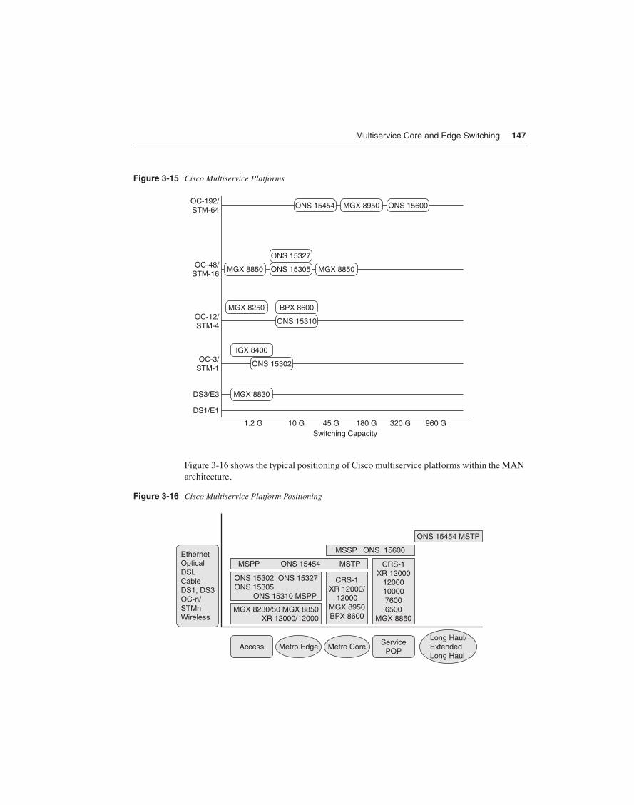
Multiservice Core and Edge Switching 147
Figure 3-15 Cisco Multiservice Platforms
Figure 3-16 shows the typical positioning of Cisco multiservice platforms within the MAN architecture.
Figure 3-16 Cisco Multiservice Platform Positioning
1.2 G 10 G 45 G 180 G 320 G 960 G
DS1/E1
DS3/E3
OC-3/STM-1
OC-12/STM-4
OC-48/STM-16
OC-192/STM-64
Switching Capacity
MGX 8950
MGX 8850MGX 8850
ONS 15454
ONS 15305
ONS 15310
ONS 15302
IGX 8400
MGX 8830
BPX 8600MGX 8250
ONS 15327
ONS 15600
ServicePOP
EthernetOpticalDSLCableDS1, DS3OC-n/STMnWireless
AccessLong Haul/ExtendedLong Haul
Metro CoreMetro Edge
CRS-1XR 12000
120001000076006500
MGX 8850
CRS-1XR 12000/
12000MGX 8950BPX 8600
ONS 15302 ONS 15327ONS 15305 ONS 15310 MSPP
MGX 8230/50 MGX 8850XR 12000/12000
MSPP ONS 15454 MSTP
MSSP ONS 15600
ONS 15454 MSTP

148 Chapter 3: Multiservice Networks
Technology Brief—Multiservice NetworksThis section provides a brief study on multiservice networks. You can revisit this section frequently as a quick reference for key topics described in this chapter. This section includes the following subsections:
• Technology Viewpoint—Intended to enhance perspective and provide talking points regarding multiservice Networks.
• Technology at a Glance—Uses figures and tables to show multiservice networking fundamentals at a glance.
• Business Drivers, Success Factors, Technology Application, and Service Value at a Glance—Presents charts that suggest business drivers and lists those factors that are largely transparent to the customer and consumer but are fundamental to the success of the provider. Use the charts in this section to see how business drivers are driven through technology selection, product selection, and application deployment in order to provide solution delivery. Additionally, business drivers can be appended with critical success factors, and then driven through the technology, product, and application layers, coupled as necessary with partnering, to produce customer solutions with high service value.
Technology ViewpointMultiservice networks are chiefly found in the domain of established service providers that are in the long-standing business of providing traditional voice, TDM leased lines, Frame Relay, ATM, and, more recently, IP communication-networking solutions.
Multiservice networks provide more than one distinct communications service type over a common physical infrastructure. Multiservice implies not only the existence of distinct services within the network, but also the ability of a common network infrastructure to support all of these communication applications natively without compromising QoS for any of them.
The initial definition for multiservice networks was a converged ATM and Frame Relay network supporting these data in addition to circuit-switched voice. Recently, next-generation multiservice networks have emerged, adding Ethernet, Layer 3 IP, VPNs, Internet, and MPLS services to the mix. These next-generation service provider multiservice networks are manifested in the form of technology enhancements to the networking fundamentals of ATM, SONET/SDH, and, since the late 1990s, IP/MPLS.
Characteristically, multiservice networks have a large local and/or long-distance voice constituency: a revenue base that is still projected to make up a large share of provider income in the near term. To protect and enlarge this monetary base will require adept handling of new VoIP transport and service capabilities.

Technology Brief—Multiservice Networks 149
The growing trend in packet telephony adoption is one of the significant new revenue opportunities for service providers. It is important for two reasons. Voice revenue is still projected to make up the primary revenue contribution to multiservice-based providers in the near term. A voice portfolio that meets the value distinctions of the customer base is an absolute business fundamental to engage and collect on these revenue opportunities. Secondly, leading service providers are looking to provide managed voice services as a counter-measure to eroding transport revenues. As traditional circuit-switched voice services and equipment have matured, the resulting commoditization pressures margins into a downward price spiral, as evidenced by the continuous decline in cost per minute and the rise of flat-rate pricing for customary voice services. Service providers need a way to reestablish value in voice offerings, and customer-oriented, managed voice services based on packet telephony is that channel.
Even with the existence of next-generation technology architectures, most providers are not in a position to turn over their core technology in wholesale fashion. Provider technology is often on up-to-decade-long depreciation schedules, and functional life must often paral-lel this horizon, even if equipment is repurposed and repositioned in the network. Then there is the customer-facing issue of technology service support and migration. Though you might wish to quiesce a particular technology-based offering, the customer is not often in support of your timetable. This requires a deliberate technology migration supporting both heritage services along with the latest feature demands by the market. Since providers can-not recklessly abandon their multiyear technology investments and installed customer ser-vice base, gradual migration to next-generation multiservice solutions becomes a key requirement. Next-generation technology evolution is often the result, allowing new net-working innovations to overlap established network architectures, bridging and migrating precommitted service delivery to the latest growth markets.
From a global network perspective, the ascendancy of IP traffic has served ATM notice. According to IDC, sales of multiservice ATM-based switches were down 21 percent in 2002, 12 percent in 2003, and another 6 percent in 2004. Both Frame Relay (holding at about 20 percent) and ATM revenues are near plateau, forecasting only modest capacity-driven growth through 2007. Providers with ATM requirements are looking to add MPLS capabilities to their core infrastructures and to push IP features to the edge of the network. Responsible for the development of tag switching, the technology behind the MPLS IETF standard, Cisco Systems has an enviable leadership position in MPLS integration across both ATM and IP networking platforms.
The vast installed base of the Layer 1 SONET/SDH optical infrastructure must also be considered in any measured technology migration. The primary appeal for multiservice provisioning and switching platforms, known in the market as MSPPs and MSSPs, is to consolidate long-established SONET/SDH ADMs in the multiservice metro edge, core, and service POPs, while incorporating new Layer 3 IP capabilities with packet interfaces for Ethernet, Fast Ethernet, and Gigabit Ethernet opportunities. Many contain additional sup-port for multiservice interfaces and DWDM. Deployed as a springboard for the rapid provi-sioning of multiple services, the intrinsic value in these new-generation multiservice

150 Chapter 3: Multiservice Networks
provisioning platforms is to build a bridge from circuit-based transport to packet-based ser-vices. Also seen as an edge services platform with which to migrate Frame Relay and other established data services, MSPPs and MSSPs help providers to execute that strategy while maintaining established TDM services and leveraging SONET/SDH capabilities. Entering the market near the end of many legacy SONET/SDH ADM depreciation schedules, the MSPPs inherit a sizable portion of their justification from reduced power, space, and main-tenance requirements. In doing so, MSPPs help with continued optimization of operating budgets while representing strategic capital investments for new, high-value IP service opportunity.
Multiservice providers are clearly building IP feature-based networks that have scale. Carriers are moving dramatically to embrace IP/MPLS networks, which combine the best features of Layer 3 routing with Layer 2 switching. MPLS provides the simplicity and feature-rich control of IP routing with the performance and throughput of ATM switching. MPLS allows one to restrict IP processing to the appropriate place—on the edges of the network. IP- and MPLS-based routers can operate at much higher speeds, more economically than can an ATM switch.
Layer 3 MPLS VPNs based on RFC 2547 are at the top of the requirements list for multiservice network providers. MPLS VPN offerings can help enterprise customers transfer complex routing responsibilities to the provider network. This allows providers to increase value for Layer 2 and Layer 3 IP-managed services. These network enhancements will start in-region, and then move to out-of-region when and wherever opportunity dictates. Where regional Bell operating company (RBOC) providers have Section 271 approvals to provide long-distance voice and data, IP/MPLS-based networks will afford the opportunity to compete nationally for data services against North American Inter-eXchange Carriers.
The new era of networking is based on increasing opportunity through service pull, rather than through technology push. Positioning networks to support multiple services, while operationally converging multiple streams of voice, video, and IP-integrated data, is the new direction of multiservice network architecture. In the face of competitive pressures and service substitution, not only are next-generation multiservice networks a fresh direction, they are an imperative passage through which to optimize strategic investment and expense.
Technology at a GlanceFigure 3-17 shows the typical positioning of Cisco multiservice platforms within the MAN architecture.

Technology Brief—Multiservice Networks 151
Figure 3-17 Cisco Multiservice Platforms
Table 3-6 summarizes multiservice technologies.
Table 3-6 Multiservice Technologies
ATM, IP+ATM IP/MPLS MSPP MSSP
Key Standards ATM UNI V3.1
ANSI T1.816
ANSI T1.408
ITU-T I.361, I.362, I.363
ITU-T I.555, I.356, I.432
ITU-T I.36x.1
ITU-T H.222
ITU-T Q.2100, Q.2110
ITU-T Q.2130, Q.2931
ITU-T Q.931, Q.933
E1 G.703, G.704, G.804
RFC 2547-BGP/MPLS VPNs
RFC 2702 Requirements for Traffic Engineering over MPLS
RFC 3031-MPLS architecture
RFC 3032-MPLS label stack encoding
RFC 3034-Use of label switching on Frame Relay networks specification
RFC 3035-MPLS using LDP and ATM VC switching
RFC 3036-LDP specification
NEBS Level 3
GR-1089-CORE
GR-63-CORE
European Telecommunication Standards Institute (ETSI) EN300-386
SONET GR-253-CORE
SDH ITU-T G.707
GR-1400-CORE
G.781, G.782, G.783, G.811, G.812, G.813, G.823, G.825, G.826, G.829
IEEE 802.3, 802.1p, 802.1Q, 802.1D
NEBS Level 3
GR-1089-CORE
GR-63-CORE
European Telecommunication Standards Institute (ETSI) EN300-386
SONET GR-253-CORE
SDH ITU-T G.707
GR-1400-CORE
G.781, G.782, G.783, G.811, G.812, G.813
OSMINE-certified TIRKS, NMA, transport (formerly TEMS)
continues
ServicePOP
EthernetOpticalDSLCableDS1, DS3OC-n/STMnWireless
AccessLong Haul/ExtendedLong Haul
Metro CoreMetro Edge
CRS-1XR 12000
120001000076006500
MGX8850
CRS-1XR 12000/
12000MGX 8950BPX 8600
ONS 15302 ONS 15327ONS 15305 ONS 15310 MSPP
MGX 8230/50 MGX 8850XR 12000/12000
MSPP ONS 15454 MSTP
MSSP ONS 15600
ONS 15454 MSTP

152 Chapter 3: Multiservice Networks
Key Standards(Continued)
RFC 1483, RFC 1695
SONET GR.253.CORE
SDH ITU-T G.707
GFP ITU-G.7041
Optical Fiber ITU-T G.652/653
DWDM ITU-T G.692
RFC 3037-LDP applicability
RFC 3038-VCID notification over ATM link for LDP
OSMINE-certified TIRKS, NMA, transport (formerly TEMS)
SNMP V1, V2, TL1
SNMP V1, V2, TL1
IEEE 802.3
Processor Architecture Technology
MGX 8200/8800 PXM-1 shared memory switching architecture at 1.2 Gbps
MGX 8850/8950 PXM-45 dual-processor, dual-core architecture, 45 Gbps, and 2.2 Gbps cell bus
MGX8950 XM-60 – 60 Gbps nonblocking cross-point switch fabric
RPM-PR 400 Kpps
RPM-XF 2.6 Mpps
7200/7300/7400/10000 - Shared memory with hardware assist
6500/7600 crossbar to 720 Gbps
XR 12000/12000/ CU11 IBM PowerPC with distributed crossbar multifabric, multilink
CRS-1/ Dual PowerPC CPU complex per Route Processor. Line cards with Cisco Silicon Packet Processor ASIC with 188 32-bit RISC CPUs. 3-stage Benes architecture switch fabric
ONS 15454
Nonblocking XC and XCVT at VC4-Xc and VC12/3-Xc (future)
XC10G
XC-VXL-10G & 2.5G
ONS 15600
Core cross-connect CXC or SSXC
320 Gbps fabric
Multishelf up to 5-terabit scalability
Table 3-6 Multiservice Technologies (Continued)
ATM, IP+ATM IP/MPLS MSPP MSSP

Technology Brief—Multiservice Networks 153
Backplane Switching Speed Range
Backplane Switching
1.2 Gbps to 180 Gbps
MGX 8200/8800 PXM-1 at 1.2 Gbps
MGX 8850/8950 PXM-45, 45 Gbps, and 2.2 Gbps cell bus
MGX 8950
XM-60 – 60 Gbps nonblocking cross-point switch fabric up to 4 XM-60s for 240 Gbps or 180 Gbps redundant
Backplane Routing/Switching
7200/7300/7400/7500 up to 1 Mpps
6500/7600 32 Gbps up to 720 Gbps and 15 to 30 Mpps
10000/51.2 Gbps
XR 12000/12000 30 Gbps to 1.2 Tbps
CRS-1 single-shelf 640 Mbps/1.28 Tbps
Multishelf up to 92 Tbps
Backplane Switching
240 Gbps total
Data plane 160 Gbps
SONET plane 80 Gbps
10 DCC to 68 DCC
288 STS1 & 672 VT1.5 to 1152 STS1 & 672 VT1.5
Backplane Switching
40 Gbps per slot x 8 slots
STS/VC-4 switching fabric at 320+ Gbps
6144 STS1 to 2048 OC-48 switching capacity
Interface Speed Support
T1/E1 (DS0/DS1)
T3/E3
OC-3/STM-1
OC-12/STM-4
OC-48/STM-16
OC-192/STM-64
T1/E1 (DS0/DS1)
T3/E3
OC-3/STM-1
OC-12/ STM-4
OC-48/ STM-16
OC192/STM-64
Fast/Gigabit/10 Gigabit Ethernet
CRS-1
OC-768/ STM-256
T1/E1
T3/E3
OC-3/STM-1
OC-12/STM-4
OC-48/STM-16
OC-192/STM-64
E100T-12/E100-12-G
E1000-2/E1000-2-G
G1000-4/G1K-4
ML100T-12/ML1000-2
CE100T-8
FC-MR-4
Gigabit Ethernet
OC-3/STM-1
OC-12/STM-4
OC-48/STM-16
OC192/STM-64
OC-768/STM-256
continues
Table 3-6 Multiservice Technologies (Continued)
ATM, IP+ATM IP/MPLS MSPP MSSP

154 Chapter 3: Multiservice Networks
Key Capacities MGX 8250
Up to 192 T1/E1
1,344 T1 channelized
8 T3/E3
8 OC-3/STM-1
MGX 8850/8950
Up to 192 T1/E1
1,344 T1 channelized
192 T3/E3
192 OC-3/STM-1
48 OC-12/STM-4
12 OC-48/STM-16
MGX 8950
Up to 768 T3
768 OC-3/STM-1
192 OC-12/STM-4
48 OC-48/STM-16
12 OC-192/STM-64
7200/7300
NPE-G100 up to 1 Mpps supports interfaces from DS0 to OC-48/STM-16
6500/7600
Up to 30 Mpps and 720 Gbps switching with 3 to 13 line card slots
10000
8 x 3.2 Gbps per line card slot or 16 x 1.6 Gbps per line card slot
XR 12000/12000
4, 6, 10, and 16 line card slots at up to 40 Gbps each on 128XX series
CRS-1
Single-shelf with 8/16 40 Gbps line card slots
Multishelf, multifabric configuration up to 1,152 40 Gbps line card slots
1,152 OC-768/STM-256 POS
4,608 OC-192/STM-64 POS/DPT
9,216 10 Gigabit Ethernet
18,432 OC-48/STM-16 POS/DPT
140 x DS1 252 x E1
192 x DS3
248 x E3
48 x OC-3/STM-1
16 x OC-12/STM-4
12 x OC-48/STM-16
6 x OC-192/STM-64
144 x FastE
48 x GE
32-64 x FC/FICON
10 Gbps MR-TXP
Nonblocking VC-4 cross-connect capacity (line/line, trib/trib, line/trib)
Uni- and bi-directional cross-connect
HO cross-connect size 384 x 384 VC-4
Up to 5 rings supported per system - 4 SNCP and 1 MS SPRing or 5 SNCP
3,072 STS-1 bidirectional cross-connects
128 OC-3/STM-1
128 OC-12/STM-4
128 OC-48/STM-16
32 OC-192/STM-64
64 UPSR/SNCP any combination of UPSR/SNCP, BLSR/MSSPRing, and 1+1 APS/MSP can be mixed with allowable maximums
32 two-fiber BLSR/MS-SPRing
64 1+1 APS/MSP uni- or bidirectional
PPMN
Table 3-6 Multiservice Technologies (Continued)
ATM, IP+ATM IP/MPLS MSPP MSSP

Technology Brief—Multiservice Networks 155
Bandwidth Range
Narrowband to broadband to 10 Gbps
Narrowband to broadband to 40 Gbps
Narrowband to broadband to 10 Gbps
Broadband switching to 40 Gbps
Service Provider Applications
ATM
Frame Relay
Voice adaptation transport
Private line
DSL aggregation
MSC for WCDMA
High-density broadband ATM aggregation
Multiservice bandwidth aggregation
Distributed content storage
IP VPN
Broadband access
Wireless switched voice
Wireless trunking
Class 4 replacement
ATM/Frame Relay convergence
Metro Ethernet
Broadband aggregation
ETTX aggregation
IP/MPLS core (long haul and regional)
Peering
Optical private line aggregation (OC-48 to DS0)
ATM/Frame Relay transport services (over an IP/MPLS core)
Digital cross-connect
Terminal mode
Linear add/drop multiplexer
Two-fiber UPSR/SNCP/BLSR
Four-fiber BLSR
PPMN
Two-fiber MS-SPRing
Four-fiber MS-SPRing
Multiring interconnection
Extended SNCP
Virtual rings
Hybrid SDH network topology
Regenerator mode
Wavelength multiplexer
Multiring (mixed UPSR/SNCP, BLSR/MS-SPRing, and 1+1 APS/MSP)
Linear ADM
Mesh
Regenerator
Star/hub
continues
Table 3-6 Multiservice Technologies (Continued)
ATM, IP+ATM IP/MPLS MSPP MSSP

156 Chapter 3: Multiservice Networks
Provider and Customer Applicability
Voice networking
Private line aggregation
MPLS core and edge services
L2 MPLS (EoMPLS)
L3 MPLS
WAN aggregation
IP/VPN
Storage area networks
Disaster recovery
Internet access
L2 Ethernet switching to 10 Gigabit Ethernet
L2 MPLS (EoMPLS)
L3 MPLS
Metro Ethernet
Private line aggregation
Ethernet subscriber aggregation
MPLS core and edge services
WAN aggregation
Campus MAN
High-speed WAN
LAN to LAN
VPN
Storage area networks
Disaster recovery
Internet access
Private line
Storage area networks
Exchange/central office colocation and interface to LH optical core networks
Metropolitan video transport, data, and voice optical backbone networks
TLS platform
Campus and university backbone network
Business transport network
Distributed bandwidth manager
Voice switch interface
Colocation digital subscriber line access multiplexer (DSLAM) and voice aggregator and transport system
Cable TV (CATV) transport backbone network
Wireless cell site traffic aggregator
High-speed ATM/router link extender
SONET/SDH ADM, BBDXC replacement, aggregation, and TDM switching
Metro core and service POP switching
MSPP metro ring aggregation
Circuit to packet transition
Table 3-6 Multiservice Technologies (Continued)
ATM, IP+ATM IP/MPLS MSPP MSSP

Technology Brief—Multiservice Networks 157
Business Drivers, Success Factors, Technology Application, and Service Value at a Glance
Solution and services are the desired output of every technology company. Customers perceive value differently, along a scale of low cost to high value. Providers of solutions and services should understand business drivers, technology, products, and applications to craft offerings that deliver the appropriate value response to a particular customer’s value distinction.
The following charts list typical customer business drivers for the subject classification of the network. Following the lower arrow, these business drivers become input to seed tech-nology selection, product selection, and application direction to create solution delivery. Alternatively, from the business drivers, another approach (the upper arrow) considers the provider’s critical success factors in conjunction with seed technology, products and their key differentiators, and applications to deliver solutions with high service value to custom-ers and market leadership for providers.
Figure 3-18 charts the business drivers for multiservice networks
Figure 3-18 Multiservice Networks
Business Drivers
Critical Success Factors Service Value
Solution Delivery
Cisco Key Differentiators
Technology ApplicationsCiscoProductLineup
CompetitiveMaturity
MarketShare
MarketValue
Transition
MarketLeadership
Ethernet to the Internet
Worldwide Broadband Growth
MPLS Adaptation
Growth in Frame Relay, ATM
Packet Telephony Services
High-Value IP Service Demand at the Edge
Invest Strategically-Maximize CapEx
Minimize Operational Expense
Migrate Layer 2 Revenue to NextGeneration Layer 2, Layer 3 Services
Convergence of ATM, Frame Relay andIP Network Infrastructure
Increase Customer ARPU
Core Requirements for Reliability,Performance and Security
Next-Generation IP/MPLS Services
Enhanced Service Offerings Portfolio
Managed Packet Telephony Services
MPLS Core and Edge Solution
MPLS Traffic Engineering
Metro IP Solutions
Cisco Voice Infrastructure andApplications Solution
Cisco Business Voice Solution
Metro Ethernet Switching Solution
Mobile Switching Center for WCDMA
Managed High-Value IP Services
Carrier-Class LAN/WAN/MAN Services
SLA Guaranteed Service Offerings
Cisco IOS
TDM
Optical
SONET/SDH
FrameRelay
ATM
Ethernet
IP
MPLS
MGCP
PNNI
VoiceServices
PacketTelephonyServices
IP VPNSL2 MPLSL3 MPLS
MetroEthernet
DSL, Cable,WirelessTraffic
Aggregation
InternetAccess
IP Services
BusinessContinuity
and RemoteStorage
Video onDemand
BPX 8620BPX 8650
MGX 8250MGX 8850MGX 8950MGX 8830
MGX8230/8220IGX 8400,LS1010
C8500 MSR
ONS 15302ONS 15305ONS 15310ONS 15327ONS 15454ONS 15600
7200/73007400/75006500/7600
10000 Series
XR12000/12000
Series
Cisco CRS-1
Service and Technology Flexibility – RapidProvisioning – Cisco IOS Leverage –
Industry Leading IP and MPLS – Service Density– Carrier-Class High-Availability Features –
Service Providers - Verizon-BellSouth-SBC-Qwest-Sprint-AT&T-MCI-Infonet-Level 3Equipment Manufacturers - Nortel-Alcatel-Lucent-Cisco Systems-Marconi-Ericsson-WaveSmith-Vivace-AFC Telliant-Equipe-Laurel-net.com-Juniper
LowCost
HighValue
IndustryPlayers
Multiservice Networks
Out Tasking of Network Services

158 Chapter 3: Multiservice Networks
End Notes1 IDC. Worldwide ATM Switch 2005–2009 Forecast. Study # 33066, March 2005
References Used in This ChapterPignataro, Carlos, Ross Kazemi, and Bil Dry. Cisco Multiservice Switching Networks. Cisco Press, 2002
Yankee Group Report. “Multiservice WAN Switch Market at a Crossroads.” April 11, 2003
Cisco Systems, Inc. “Defining the Multiservice Switching Platform.” http://www.cisco.com/en/US/partner/products/hw/optical/ps4533/products_white_paper09186a00800dea5e.shtml (Must be a registered Cisco.com user.)
Finch, Paul. “Introducing the Cisco ATM Advanced Multiservice Portfolio.” http://www.cisco.com/networkers/nw03/presos/docs/PRD-8059.pdf
Cisco Systems, Inc. “Requirements for Next-Generation Core Routing Systems.” http://www.cisco.com/en/US/partner/products/ps5763/products_white_paper09186a008022da42.shtml
Related Documents