This chapter covers the following topics: • IP phones and lines • Shared lines • Hunt groups • Intercoms • Paging • Line overlays • Call pickup • Softkey customization • Call transfer and forward

Welcome message from author
This document is posted to help you gain knowledge. Please leave a comment to let me know what you think about it! Share it to your friends and learn new things together.
Transcript

This chapter covers the following topics:
• IP phones and lines
• Shared lines
• Hunt groups
• Intercoms
• Paging
• Line overlays
• Call pickup
• Softkey customization
• Call transfer and forward
C H A P T E R 5
Cisco CME Call Processing Features
This chapter describes the primary call processing features of Cisco CallManager Express (CME) and shows how you can combine them to produce an extensive set of call handling behaviors. It includes a basic discussion of the advantages of IP telephony for the small office and relates these to the more traditional time-division multiplexing (TDM) or analog-based telephone systems historically used in the small private branch exchange (PBX) and Key System marketplace.
This chapter explains the terminology and Cisco IOS commands (command-line interface [CLI]) used to configure IP phones, extension lines, shared lines, overlays, intercom, paging, call park and pickup, hunt groups, and other forms of call coverage. One of the key perspectives to understanding Cisco CME is that it is built on top of a Cisco IOS router. This means that the same modular feature approach that dominates the general Cisco IOS command-line organization is carried forward into the Cisco CME structure. The result is that individual component features are designed to be as modular and flexible as possible. It also means that it is often possible to combine features to produce some fairly complex operations. Some of these combinations are not obvious from a quick glance at the CLI. This chapter is intended to help you understand and use some of the available flexibility.
The sample configurations in this chapter are presented using the Cisco IOS CLI. Many of the configurations described can also be generated using the web browser graphical user interface (GUI). In both cases, the configurations generated are stored identically in the router’s nonvolatile memory in CLI format. The CLI presentation is more compact and easier to grasp than an equivalent series of GUI screen shots. The CLI presentation also shows the integration of some Cisco CME-specific functions with the CLI commands for related but generic Cisco IOS router functions, because the generic Cisco IOS commands usually don’t have a GUI equivalent. The CLI format is also convenient for many readers who may already be very familiar with the Cisco IOS CLI. The GUI is more extensively covered in Chapter 13, “Cisco IPC Express General Administration and Initial System Setup,” and Chapter 14, “Configuring and Managing Cisco IPC Express Systems.”
The objective of this chapter is to give you a broad understanding of the options that Cisco CME provides. It’s not meant to be an exhaustive manual on how to configure a Cisco CME system to meet every possible combination of network design circumstances you might encounter. System configuration is covered in Chapter 14. For the more sophisticated

112 Chapter 5: Cisco CME Call Processing Features
configurations, consult the detailed Cisco IOS feature and Cisco CME administration documentation available online at Cisco.com.
The less-complex configurations are generally simple to build, even using the CLI. At the same time, the broad range and component-level adaptability of the Cisco IOS software platform is available if required to deal with the complexity of real-life network situations. Hopefully by reading this chapter, you will at least have a good idea of what you’re looking for when you decide to tackle the extensive Cisco IOS, voice over IP (VoIP), and Cisco CME documentation that’s available online.
IP Phones and IP Phone LinesIP phones may appear to be very similar in appearance to the digital phones used with a TDM-based PBX, at least on initial inspection. IP phones do behave in very similar ways for basic call operations. When you lift the handset, you hear dial tone. When an incoming call arrives, the phone rings. Phone users expect this behavior, which makes the introduction of IP phone technology as a replacement for traditional TDM-based telephony relatively painless for the vast majority of (nontechnical) phone users. In the case of traditional TDM-based telephony, the basis of the phone user interface is rooted in the physical structure of the typical digital TDM PBX. This in turn has its roots in the analog PBX systems that preceded it.
With IP telephony, some conscious and deliberate effort has gone into replicating the traditional phone user interface, because many of the historic engineering considerations that dictated design in the TDM PBX world are no longer applicable. This is well illustrated by considering the idea of “phone extensions” or “phone lines” for IP phones. In an analog PBX or Key System, the number of twisted-pair cables connected to the phone determines how many lines the phone has access to. If you want more phone lines, you have to add more wires. This is still mostly true for digital TDM phones. An example is a Basic Rate Inerface (BRI) phone with a twisted-pair cable carrying 2B + D—that is, two bearer channels (audio) plus one data channel (signaling).
For an IP phone, there is no direct relationship between the physical wiring and the number of lines that an IP phone supports. IP phones based on 100-Mbps Ethernet connections can theoretically support hundreds of phone lines. How many lines an IP phone supports is instead determined solely by the design of the phone user interface, not the physical connectivity to the system equipment cabinet. The user interface might be a traditional looking one that has a dedicated physical button for each line the phone supports. Alternatively, the IP phone might simply have a touch screen. In this case, the number of square inches available on the display may determine the maximum number of lines accessible to the user. Other variations on user interface design might include the use of pull-down menus or scroll bars to select a phone line. The extreme example of this is the PC softphone. A softphone is simply an application program running on a PC where you select a phone line from the PC display with a mouse click.
The next section describes how Cisco CME deals with phones and phone lines.

IP Phones and IP Phone Lines 113
Cisco CME Ephone and Ephone-dnIn the Cisco CME product, an IP phone device is called an ephone (short for Ethernet phone). The phone lines that are associated with the ephone are called ephone-dn (Ethernet phone directory number [DN]). An ephone-dn is made up of the following two subcomponents:
• Virtual voice port
• Dial peer
The virtual voice port is the nearest direct equivalent to a physical phone line in a Cisco CME system. The virtual voice port is the object that maintains the call state (on-hook or off-hook). The dial peer is the object that determines the phone number associated with the virtual voice port. A dial peer can do many additional things besides control the virtual voice port’s phone number, such as apply translations to called and calling numbers. A virtual voice port can be associated with multiple dial peers and, therefore, can have multiple phone numbers associated with it.
Figure 5-1 shows that ephone-dn 7 creates, or is associated with, virtual voice port 50/0/7 and a plain old telephone service (POTS) dial peer that references virtual voice port 50/0/7. The dial peer contains the voice port’s phone number. It is used for call-routing purposes for incoming calls. The virtual voice port contains the station ID that sets the caller ID properties (name and number) for the ephone-dn (used for outgoing calls).
Figure 5-1 Ephone-dn Components: Voice Port and Dial Peer
The terms dial peer and voice port are inherited from the Cisco IOS router voice infrastructure functions that have historically been used for applications such as VoIP gateways in toll-bypass networks (using protocols such as H.323, Session Initiation Protocol [SIP], and Media Gateway Control Protocol [MGCP]). In the router voice gateway context, a voice port typically refers to an interface that connects to the Public Switched Telephone Network (PSTN) (or PBX), but it also includes interfaces that directly connect to analog telephones. The behavior and usage of a virtual voice port is similar in many ways to a physical voice port used to connect to an analog telephone (specifically, a Foreign Exchange Station [FXS]). As a result of this similarity, you will see virtual voice ports called eFXS voice ports. In this terminology, the term eFXS means ephone-dn virtual FXS voice port.
creates
virtual voice-port 50/0/7 station-id number 1001 station-id name John
dial-peer voice 20007 pots destination-pattern 1001 port 50/0/7
ephone-dn 7 number 1001
name John
114 Chapter 5: Cisco CME Call Processing Features
You can configure a virtual voice port to have one or two subchannels. Each subchannel can accept a single voice call. This arrangement is similar to the two bearer channels present on an ISDN BRI voice port. An ephone-dn that is configured in dual-line mode creates a virtual voice port that can handle two simultaneous calls. The primary use of the dual-line option is to provide a simple way to handle features such as call waiting. The dual-line option also provides a way to support the second call instance required by features, such as third-party conferencing and call transfer with consultation.
When you select the dual-line option, the Cisco IP phone provides a rocker button or (blue) navigation bar that is used as a scroll key to select between two call instances presented on the IP phone display. For example, in the case of call waiting, the phone display shows you the active (connected) call and the waiting (ringing) call. You can press the hold softkey to place the active call on hold, use the navigation bar to scroll the IP phone display, and then select the answer softkey for the waiting call.
Alternatively, call waiting can be supported simply by using an IP phone that has two (or more) physical line buttons. In this case, you configure each button with a separate phone line instance (ephone-dn). Instead of configuring a single ephone-dn in dual-line mode, you configure two ephone-dns with the same phone number using the default ephone-dn single-line mode (and the no huntstop option, which you’ll learn more about later, in the section “Cisco IOS Voice Dial Peer Hunting”). This provides a simpler and more traditional multiline user interface. You perform navigation between two simultaneous calls by simply pressing one of the line buttons to select the desired call. The previously active call is automatically placed on hold. This mode of operation is often called one button, one call.
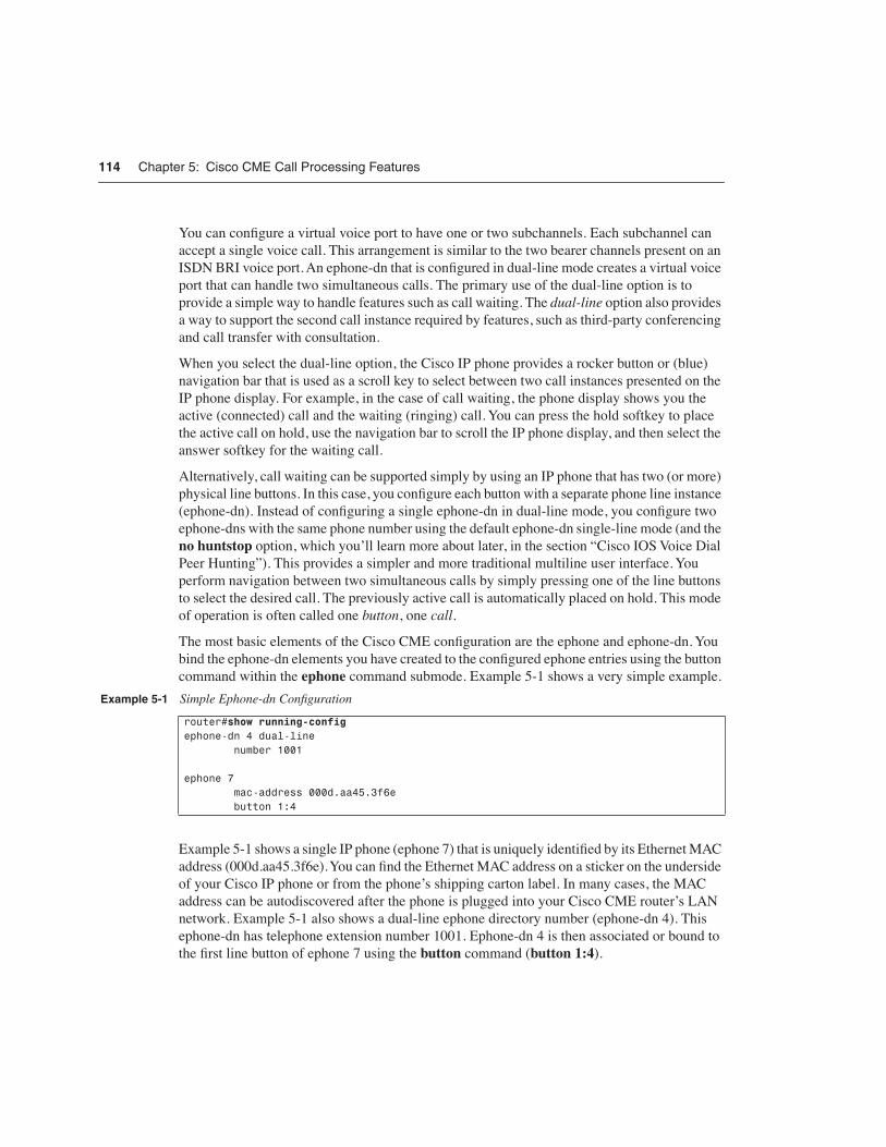
The most basic elements of the Cisco CME configuration are the ephone and ephone-dn. You bind the ephone-dn elements you have created to the configured ephone entries using the button command within the ephone command submode. Example 5-1 shows a very simple example.
Example 5-1 shows a single IP phone (ephone 7) that is uniquely identified by its Ethernet MAC address (000d.aa45.3f6e). You can find the Ethernet MAC address on a sticker on the underside of your Cisco IP phone or from the phone’s shipping carton label. In many cases, the MAC address can be autodiscovered after the phone is plugged into your Cisco CME router’s LAN network. Example 5-1 also shows a dual-line ephone directory number (ephone-dn 4). This ephone-dn has telephone extension number 1001. Ephone-dn 4 is then associated or bound to the first line button of ephone 7 using the button command (button 1:4).
Example 5-1 Simple Ephone-dn Configuration
router#show running-configephone-dn 4 dual-line number 1001
ephone 7 mac-address 000d.aa45.3f6e button 1:4

IP Phones and IP Phone Lines 115
Example 5-2 shows a slightly expanded view of the CLI configuration in Example 5-1.
The configuration shown in Example 5-2 is all that’s needed to register your first IP phone provisioned with a single line button and to produce dial tone when you lift the handset. The only assumptions made here are that the phone is a Cisco 7960 IP Phone, that the phone firmware desired is the file P00303020214.bin, and that the firmware file is loaded into the router’s Flash memory.
The tftp-server, ip dhcp pool, and interface FastEthernet 0/1 commands shown are standard Cisco IOS CLI router commands that are outside the scope of this book, but you are most likely familiar with their basic function in the IP world. These commands are included just to provide a context for the Cisco CME-specific commands ephone, ephone-dn, and telephony-service.
Cisco CME also has a telephony-service setup command that you can use to bring up a set of phones and provide basic service. This command includes automatic creation of the Dynamic Host Configuration Protocol (DHCP) pool CLI entry if you need it.
Example 5-2 Expanded Ephone-dn Configuration
router#show running-configtftp-server flash:P00303020214.bin
ip dhcp pool cmenetwork 192.168.0.0 255.255.255.0default-router 192.168.0.1option 150 ip 192.168.0.1
interface FastEthernet0/1 ip address 192.168.0.1 255.255.255.0duplex autospeed auto
telephony-service ip source-address 192.168.0.1 load 7960-7940 P00303020214 max-ephones 24 max-dn 24 create cnf-files
ephone-dn 4 dual-line number 1001
ephone 7 mac-address 000d.aa45.3f6e button 1:4
116 Chapter 5: Cisco CME Call Processing Features
Using a PBX Versus a Key SystemThe Cisco CME product addresses phone systems in the roughly 1-to-240-phone marketplace. This product spans the range from a small, independent, four-person professional services office (perhaps running on a Cisco 2801 router) to a mid-sized company to a large branch office of a multinational enterprise (running on a Cisco 3845 router). This marketplace has traditionally been addressed by a range of simple Key Systems (with perhaps two PSTN trunk lines and four extensions) to hybrid and small PBX systems (with multiple T1 Primary Rate Interface [PRI] digital PSTN interface trunks). Within this market space, the phone user interface expectations include simple one-extension per-phone configurations (usually with call waiting) to direct PSTN trunk appearance presence on all phones (any phone can answer any PSTN call).
The next sections describe typical deployments for PBX systems and Key Systems.
PBX Usage: One Phone Line and One PhoneIn a typical PBX-like deployment, you expect to see digital PSTN trunk lines, with direct inward dial (DID) for direct access to individual phone extensions and one or more receptionists. The receptionist answers calls to the company’s primary public phone number and transfers these calls to the individual phone users. Each phone user has his or her own private extension number (and probably also a personal voice mailbox to handle busy or unanswered calls). In this arrangement, each IP phone normally has only a single phone number associated with it. You saw a sample configuration for the one-phone-to-one-extension case in Example 5-1.
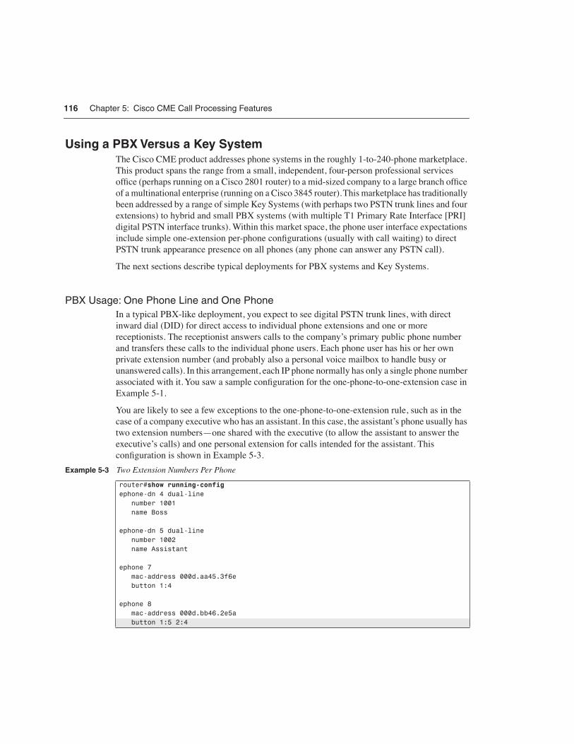
You are likely to see a few exceptions to the one-phone-to-one-extension rule, such as in the case of a company executive who has an assistant. In this case, the assistant’s phone usually has two extension numbers—one shared with the executive (to allow the assistant to answer the executive’s calls) and one personal extension for calls intended for the assistant. This configuration is shown in Example 5-3.
Example 5-3 Two Extension Numbers Per Phone
router#show running-configephone-dn 4 dual-line number 1001 name Boss
ephone-dn 5 dual-line number 1002 name Assistant
ephone 7 mac-address 000d.aa45.3f6e button 1:4
ephone 8 mac-address 000d.bb46.2e5a button 1:5 2:4

IP Phones and IP Phone Lines 117
In Example 5-3, ephone 7 is the executive’s phone, with extension 1001 on line button 1. Ephone 8 is the assistant’s phone, with the assistant’s personal extension 1002 on button 1 and the executive’s extension 1001 shared on button 2. When a call arrives for 1001, both phones ring, and either phone can answer the call. When a call arrives for 1002, only the assistant’s phone rings. When the executive is using extension 1001, the assistant’s phone is unable to access the line. However, the display on the IP phone indicates that that line is in use so that the assistant knows that the executive is busy with a call.
Key System: One Phone Line and Many PhonesIn the typical PBX environment described in the preceding section, an analysis of call traffic often shows that there are more internal extension-to-extension calls than external PSTN-to-extension calls. A result of this is the need for the one-person-to-one-phone-number configuration.
In a small four-person office, extension-to-extension calls may be nonexistent. It’s often easier to walk over and speak to a coworker than it is to phone him or her. In this environment, calls are predominantly PSTN-to-extension. Furthermore, incoming PSTN calls are the lifeblood of the small company, because each call can potentially be from a customer.
In this environment, often there is no need for personal extension numbers. What is important in this case is that somebody always promptly answers the incoming PSTN calls. A small four-person company, however, often cannot afford to hire a dedicated telephone receptionist. Example 5-4 gives a sample configuration for this type of environment.
Example 5-4 PSTN Lines on All Phones
router#show running-configephone-dn 1 number 4085550101 no huntstop preference 0
ephone-dn 2 number 4085550101 preference 1
ephone 1 mac-address 000d.aa45.3f6e button 1:1 2:2
ephone 2 mac-address 000d.bb46.2e5a button 1:1 2:2
ephone 3 mac-address 000d.cc47.1d49 button 1:1 2:2
ephone 4 mac-address 000d.dd48.0c38 button 1:1 2:2

118 Chapter 5: Cisco CME Call Processing Features
In Example 5-4, you see that ephone-dn 1 and ephone-dn 2 both have the same phone number. The phone number configured is the small company’s (fictitious) public PSTN phone number. This is the number that is displayed on the IP phones and also the PSTN number that customers dial to reach the company. You can configure the Cisco CME router’s PSTN interface to direct incoming PSTN calls to the first ephone-dn (for example, connection plar opx configured on an Foreign Exchange Office [FXO] port connected to the PSTN). If ephone-dn 1 is busy, calls automatically roll over to ephone-dn 2. To make this happen, you configure the ephone-dn with the same number, and then set explicit preference values to indicate the order for selection between the ephone-dns. The lower-preference 0 value attached to ephone-dn 1 indicates that ephone-dn 1 should be selected first. Also note that the no huntstop command gives the Cisco CME system permission to try to find an alternative destination for the incoming call if the first ephone-dn is busy. (You’ll read more about huntstop in the section “Cisco IOS Voice Dial Peer Hunting.”)
Note how easy it is to expand this basic two-by-four configuration to include more PSTN trunks and more IP phones. There is no specific limit on how many IP phones can share a single IP phone line. There is a limit on how many phone lines can be directly assigned to each IP phone. This limit is set by the number of available line buttons on the IP phone. For example, a Cisco 7960 IP Phone has six buttons, so you cannot directly assign more than six PSTN lines using the simple configuration method shown in Example 5-4. However, you can attach up to 60 lines to a 7960 IP Phone using a configuration option called overlay-dn. (You’ll read more about this in the section “Using Overlay-dn.”)
You can see from the examples that the simple binding arrangement between IP phone and IP phone lines creates a significant amount of flexibility. This allows the Cisco CME to support multiple styles of phone usage to meet different end-customer expectations. The PBX and Key System configuration styles are not mutually exclusive. You can combine configuration styles by simply adjusting the IP phone-to-IP phone line bindings as needed.
The one phone line and many phones configuration model applies much more broadly than just the four-person Key System example given here. Even within a larger company’s phone system, there are cases in which the one phone line and many phones model is appropriate. One example is for a company loading dock, where you might have several hundred square feet of loading/unloading storage space in a shipping and receiving department. In this situation, you may find it desirable to place multiple phones so that they are spread out across a wide physical area. In addition, any phone can be used to place and receive calls on the same line.
Implementing Shared Lines and Hunt GroupsAlthough it is widely used, the term hunt group seems to mean different things to different people and in different contexts. It’s a general term that covers the distribution of calls among a group of phones. In this chapter, the term call coverage refers to the general concept of call distribution across phones. This helps avoid confusion with the Cisco CME CLI command ephone-hunt. The ephone-hunt command is used to configure a specific kind of call coverage that involves sequential selection among a group of selected phone lines.
Implementing Shared Lines and Hunt Groups 119
Many other types of call coverage are addressed with other commands, combinations of commands, and configurations. Examples include the use of shared lines, overlay-dn, call forwarding, secondary ephone-dn numbers, and combinations of these.
This section describes a number of different types of call coverage:
• Simple sequential ringing of a selected set of phone lines
• Ringing of multiple phone lines at the same time, referred to here as parallel hunting
• Call forwarding from one line to another using call forward on busy or no-answer
• Combination sequences that involve sequential ringing of multiple phone lines, referred to here as sequential parallel hunting
Notice that all these refer to ringing phone lines, not phones. Calls are sequenced through an ordered set of phone lines. Which phones ring depends on the binding of the lines to the phones. Each line can be bound to multiple phones.
The following sections discuss several types of call coverage.
Cisco IOS Voice Dial Peer HuntingA good place to start a discussion of call coverage for Cisco CME is to look at the voice dial peer hunting mechanism that is a standard component of the Cisco IOS voice infrastructure. Dial peers have a very large number of configuration options. The most basic options are related to matching a telephone number and directing the call to a specific voice port or VoIP destination. More advanced options relate to number manipulation (using translation rules or translation profiles), application selection (including custom TCL scripts), protocol options (such as fax relay and dual-tone multifrequency [DTMF] relay), voice codec selection, and caller ID manipulation and restriction.
Some dial peer operations relate to selecting a dial peer associated with the call’s originator (incoming dial peer matching) and selecting a dial peer associated with the call destination (outgoing dial peer matching). Multiple parameters can affect the selection of the incoming and outgoing dial peers, but the primary matching criteria are the called and calling party numbers.
Describing all the dial peer options in detail is outside the scope of this book; however, numerous books deal with this subject in more depth, including the following:
• Deploying Cisco Voice over IP Solutions by Jonathan Davidson (Cisco Press, 2001).
• Cisco Voice over Frame Relay, ATM, and IP, edited by Steve McQuerry, Kelly McGrew, and Stephen Foy (Cisco Press, 2001).

120 Chapter 5: Cisco CME Call Processing Features
This section provides a simplified overview of dial peers to provide a basic understanding of some of the options that apply to call coverage—specifically, dial peer hunting. Example 5-5 shows two basic dial peers.
The first dial peer (dial peer 100) is a POTS dial peer. This type of dial peer is used to reference a local telephony voice port connected to the router.
The second dial peer (dial peer 200) is a VoIP dial peer used to reference a remote telephony device accessed via IP, usually across a WAN data link.
Both dial peers have a destination-pattern parameter. This associates a telephone number or range of telephone numbers with the dial peer. In the VoIP dial peer, you can see that the destination pattern contains the wildcard character “.” (to match any digit). In this example, the destination-pattern 20.. command matches telephone numbers in the range 2000 to 2099.
Both dial peers associate a destination device with the phone number selected by the destination pattern. In the POTS dial peer case, the destination is a physical voice port on the router designated as port 1/0/0. Your router’s exact port numbering may vary by router type and voice interface type, but the basic numbering structure is slot/card/port.
In the VoIP dial peer case, the destination is an IP address, as indicated by the session target ipv4:10.0.4.2 parameter.
In Example 5-5, you can see how a dial peer is used to associate a telephone number (or range) with a destination, either a voice port or an IP address.
The dial peer hunting function comes into play when you create two or more dial peers that match the same telephone number but reference different destination devices. You can set many parameters to adjust the order in which matching dial peers are selected. The default behavior is called longest match. For longest match, the dial peer that most exactly matches the telephone number is preferred. A longest match selects the destination pattern that matches the desired number using the fewest “.” wildcard characters. The best kind of longest match is an exact match, where no wildcards are used and the destination pattern and telephone number match literally and exactly. This is often the case with POTS dial peers, where you assign a specific phone number to a specific port.
Example 5-5 Two Basic Dial Peers
router#show running-configdial-peer voice 100 pots destination-pattern 1001 port 1/0/0
dial-peer voice 200 voip destination-pattern 20.. session target ipv4:10.0.4.2
Implementing Shared Lines and Hunt Groups 121
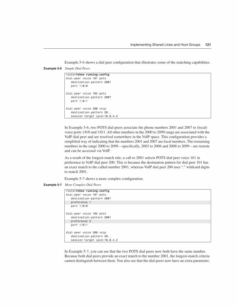
Example 5-6 shows a dial peer configuration that illustrates some of the matching capabilities.
In Example 5-6, two POTS dial peers associate the phone numbers 2001 and 2007 to (local) voice ports 1/0/0 and 1/0/1. All other numbers in the 2000 to 2099 range are associated with the VoIP dial peer and are resolved somewhere in the VoIP space. This configuration provides a simplified way of indicating that the numbers 2001 and 2007 are local numbers. The remaining numbers in the range 2000 to 2099—specifically, 2002 to 2006 and 2008 to 2099—are remote and can be accessed via VoIP.
As a result of the longest-match rule, a call to 2001 selects POTS dial peer voice 101 in preference to VoIP dial peer 200. This is because the destination pattern for dial peer 101 has an exact match to the called number 2001, whereas VoIP dial peer 200 uses “.” wildcard digits to match 2001.
Example 5-7 shows a more complex configuration.
In Example 5-7, you can see that the two POTS dial peers now both have the same number. Because both dial peers provide an exact match to the number 2001, the longest-match criteria cannot distinguish between them. You also see that the dial peers now have an extra parameter,
Example 5-6 Simple Dial Peers
router#show running-configdial-peer voice 101 pots destination-pattern 2001 port 1/0/0
dial-peer voice 102 pots destination-pattern 2007 port 1/0/1
dial-peer voice 200 voip destination-pattern 20.. session target ipv4:10.0.4.2
Example 5-7 More Complex Dial Peers
router#show running-configdial-peer voice 101 pots destination-pattern 2001 preference 1 port 1/0/0
dial-peer voice 102 pots destination-pattern 2001 preference 2 port 1/0/1
dial-peer voice 200 voip destination-pattern 20.. session target ipv4:10.0.4.2

122 Chapter 5: Cisco CME Call Processing Features
preference. The preference command is used to define a specific preference order for selecting the dial peers. The call to 2001 goes to the dial peer with the lowest preference value. The default preference value is 0.
In Example 5-7, when an incoming call to 2001 arrives, it first goes to POTS dial peer 101 with preference 1. Only if the port 1/0/0 associated with this dial peer is busy does the dial peer matching process hunt to the second dial peer 102 (preference 2). This provides the first basic mode of call coverage hunting: dial peer hunt on busy.
You may notice that there is a potential problem with the dial peer hunt-on-busy arrangement in this example: What if the second port is also busy? If ports 1/0/0 and 1/0/1 are both busy, the dial peer hunting mechanism takes the call to the next best available match. The next best match in this example is the VoIP dial peer 200. This dial peer matches the 2001 number, because it has a wildcard-based match range that spans the entire range 2000 to 2099. This range includes the number 2001.
In most cases, you do not want the call to hunt on busy into the VoIP dial peer, because (in this example) there is no resolution for the number 2001 in the VoIP space. If a call to 2001 gets routed to the VoIP destination, the call will fail with a cause code (returned by the remote VoIP system) indicating that the number 2001 does not exist. This condition returns a fast-busy tone (number not in service) indication to the caller. This is not the correct behavior. What is needed is to return a simple user busy tone indication to the caller.
You can solve this problem by adding the dial peer option huntstop, as shown in Example 5-8.
The huntstop command option tells the dial peer hunting mechanism not to try to find any further dial peer matches. Instead, the dial peer hunting stops at the dial peer containing the huntstop command. If no available voice port is found, it returns a busy tone to the caller.
Example 5-8 Huntstop in a Dial Peer
router#show running-configdial-peer voice 101 pots destination-pattern 2001 preference 1 port 1/0/0
dial-peer voice 102 pots destination-pattern 2001 preference 2 huntstop port 1/0/1
dial-peer voice 200 voip destination-pattern 20.. session target ipv4:10.0.4.2

Implementing Shared Lines and Hunt Groups 123
Example 5-9 shows another variation using dial peers to manage call coverage.
In Example 5-9, port 1/0/1 can be accessed by dialing 2001 or 2007. A call to 2001 first tries port 1/0/0. If this port is busy, it hunts to port 1/0/1. A call to 2007 goes directly to port 1/0/1.
Note that the default for the huntstop parameter under dial peer is for huntstop to be disabled. As you will see later (in the section “Cisco IOS Voice Dial Peer Hunting”), the default for huntstop when applied to the ephone-dn configuration is for huntstop to be enabled.
Ephone-dn Dial Peers and Voice PortsThe preceding section provided an overview of dial peers as used by the generic Cisco IOS voice infrastructure software. This section shows how Cisco CME uses dial peers to enable routing of calls to IP phones. The Cisco CME CLI configuration of IP phones and IP phone lines does not directly include dial peers or (virtual) voice ports. Instead, the dial peer and virtual voice port resources used by Cisco CME are hidden inside the ephone-dn command. This simplifies the configuration steps needed to create an IP phone line. It avoids the manual process of creating POTS dial peers to bind phone numbers to virtual voice ports.
Here is the original ephone-dn command from the beginning of this chapter, modified with a user name added and a specific dial peer preference included:
ephone-dn 4 number 1001 name John Smith preference 1
Example 5-9 Dial Peer Variation
router#show running-configdial-peer voice 101 pots destination-pattern 2001 preference 1 port 1/0/0
dial-peer voice 102 pots destination-pattern 2001 preference 2 huntstop port 1/0/1
dial-peer voice 102 pots destination-pattern 2007 huntstop port 1/0/1
124 Chapter 5: Cisco CME Call Processing Features
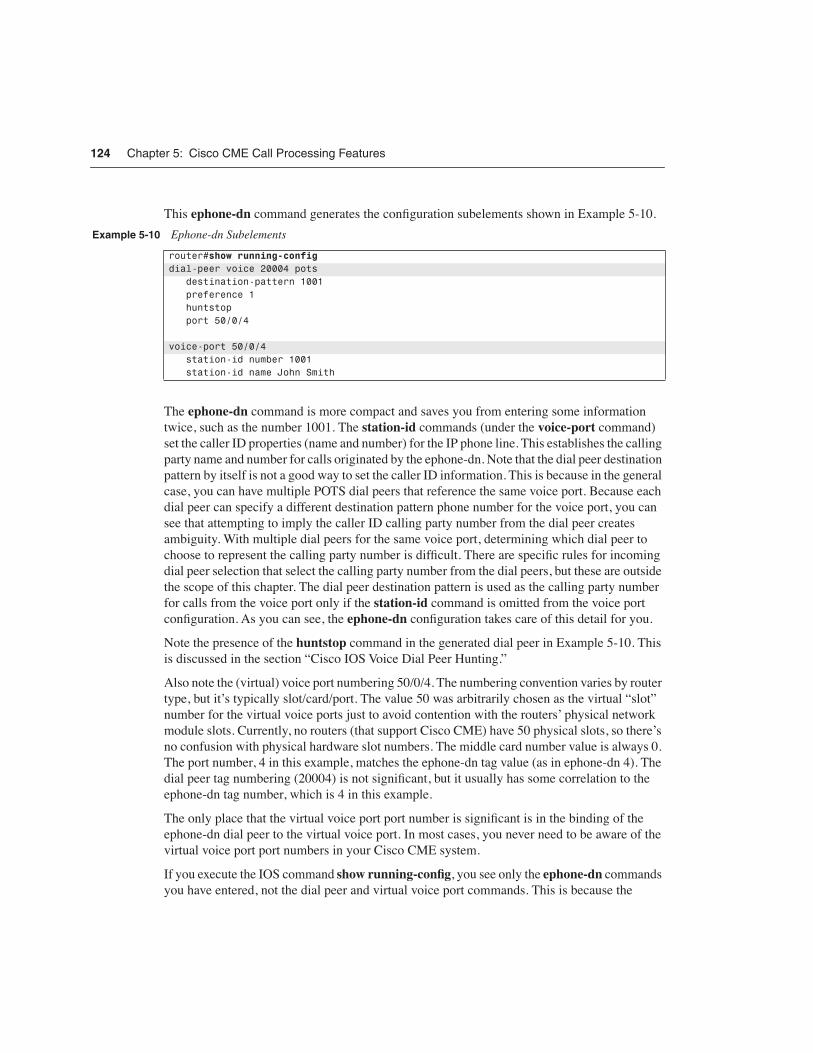
This ephone-dn command generates the configuration subelements shown in Example 5-10.
The ephone-dn command is more compact and saves you from entering some information twice, such as the number 1001. The station-id commands (under the voice-port command) set the caller ID properties (name and number) for the IP phone line. This establishes the calling party name and number for calls originated by the ephone-dn. Note that the dial peer destination pattern by itself is not a good way to set the caller ID information. This is because in the general case, you can have multiple POTS dial peers that reference the same voice port. Because each dial peer can specify a different destination pattern phone number for the voice port, you can see that attempting to imply the caller ID calling party number from the dial peer creates ambiguity. With multiple dial peers for the same voice port, determining which dial peer to choose to represent the calling party number is difficult. There are specific rules for incoming dial peer selection that select the calling party number from the dial peers, but these are outside the scope of this chapter. The dial peer destination pattern is used as the calling party number for calls from the voice port only if the station-id command is omitted from the voice port configuration. As you can see, the ephone-dn configuration takes care of this detail for you.
Note the presence of the huntstop command in the generated dial peer in Example 5-10. This is discussed in the section “Cisco IOS Voice Dial Peer Hunting.”
Also note the (virtual) voice port numbering 50/0/4. The numbering convention varies by router type, but it’s typically slot/card/port. The value 50 was arbitrarily chosen as the virtual “slot” number for the virtual voice ports just to avoid contention with the routers’ physical network module slots. Currently, no routers (that support Cisco CME) have 50 physical slots, so there’s no confusion with physical hardware slot numbers. The middle card number value is always 0. The port number, 4 in this example, matches the ephone-dn tag value (as in ephone-dn 4). The dial peer tag numbering (20004) is not significant, but it usually has some correlation to the ephone-dn tag number, which is 4 in this example.
The only place that the virtual voice port port number is significant is in the binding of the ephone-dn dial peer to the virtual voice port. In most cases, you never need to be aware of the virtual voice port port numbers in your Cisco CME system.
If you execute the IOS command show running-config, you see only the ephone-dn commands you have entered, not the dial peer and virtual voice port commands. This is because the
Example 5-10 Ephone-dn Subelements
router#show running-configdial-peer voice 20004 pots destination-pattern 1001 preference 1 huntstop port 50/0/4
voice-port 50/0/4 station-id number 1001 station-id name John Smith

Implementing Shared Lines and Hunt Groups 125
ephone-dn command automatically manages these subcommands for you, and there is no need for these to take up space in the router configuration. However, you can see the ephone-dn generated dial peers and virtual voice ports using the Cisco IOS commands show dial-peer summary and show voice-port summary.
The important point for you to understand here is that the dial peer and voice port configurations created by the ephone-dn do exist in the router configuration, even though they are not included in the output of show running-config. This point helps you understand how the Cisco CME configuration interacts with any general Cisco IOS voice infrastructure configuration that is included in your router, as well as for troubleshooting Cisco CME (covered in Part IV, “Maintenance and Troubleshooting”).
Ephone-dn Secondary NumberThe ephone-dn secondary number allows you to associate a second phone number with the same IP phone line. You can use this to create a simple hunt-on-busy configuration. This allows you to use the dial peer hunt-on-busy mechanism to make a call roll over from one line to another, even when the lines have different primary phone numbers. Example 5-11 shows an example.
This ephone-dn command generates the configuration subelements shown in Example 5-12.
Example 5-11 Ephone-dn Secondary Number
router#show running-configephone-dn 4 number 1001 secondary 1007 name John Smith preference 1 secondary 2
Example 5-12 Ephone-dn Subelements
router#show running-configdial-peer voice 20004 pots destination-pattern 1001 preference 1 huntstop port 50/0/4
dial-peer voice 30004 pots destination-pattern 1007 preference 2 huntstop port 50/0/4
voice-port 50/0/4 station-id number 1001 station-id name John Smith

126 Chapter 5: Cisco CME Call Processing Features
If you compare this with the earlier Example 5-7, you can begin to see how the ephone-dn command can leverage the IOS voice infrastructure dial peer hunting mechanism to provide simple call coverage. The configuration in this example causes incoming calls to both 1001 and 1007 to be routed to the IP phone line created by the ephone-dn 4 command, provided that no other dial peer elements in the system preempt the call routing path with a destination pattern match that has a lower numeric preference value.
Example 5-13 shows how you can use the ephone-dn secondary number to create dial peers that provide a simple form of call coverage.
Example 5-14 shows the dial peers and voice port configurations that these commands generate.
Example 5-13 Ephone-dn Secondary Number
router#show running-configephone-dn 4 number 1001 secondary 1007 name John Smith no huntstop preference 1 secondary 2
ephone-dn 5 number 1007 secondary 1001 name Jane Smith no huntstop preference 1 secondary 2
Example 5-14 Ephone-dn Subelements
router#show running-configdial-peer voice 20004 pots destination-pattern 1001 preference 1 no huntstop port 50/0/4
dial-peer voice 30004 pots destination-pattern 1007 preference 2 no huntstop port 50/0/4
dial-peer voice 20005 pots destination-pattern 1007 preference 1 no huntstop port 50/0/5
dial-peer voice 30005 pots destination-pattern 1001 preference 2 no huntstop

Implementing Shared Lines and Hunt Groups 127
With the configuration in Example 5-14, you can see that an incoming call to 1001 first goes to dial peer 20004 (preference 1) and tries virtual voice port 50/0/4 (for ephone-dn 4). If this port is busy, the call hunts on busy from dial peer 20004 to dial peer 30005 (preference 2) and tries virtual voice port 50/0/5 (for ephone-dn 5). In a similar manner, you can see that a call to 1007 first goes to ephone-dn 5 and then hunts to ephone-dn 4.
The dial peer hunting mechanism works only for hunt on busy. It does not provide hunting on no-answer timeout.
Note the use of the no huntstop command under ephone-dn. Without having this command present, the dial peer hunting stops at the first dial peer it reaches. The literal command text for no huntstop does not actually appear in the dial peers if you examine them using the show dial-peer Cisco IOS commands. This is because no huntstop is the default configuration for a dial peer, and default configuration items normally are not included in the IOS show running-config command display output. The no huntstop text is included in the preceding dial peer examples for clarity only. The no huntstop command is required under ephone-dn. This is needed to turn off the default ephone-dn configuration, which has huntstop enabled by default.
Using Call Forwarding for Call CoverageIn the examples of dial peer matching, you saw how calls can be distributed over a number of ephone-dn IP phone lines without changing the called number for the call. You can also use call forwarding to provide simple forms of call coverage. Cisco CME supports call forwarding for busy, no-answer, and unconditional (or call-forward all). When you use call forwarding to provide call coverage, the called number for the call changes. This can affect what is displayed on the IP phone receiving the forwarded call and entry into voice mail. Example 5-15 shows an example of a call forwarding configuration.
port 50/0/4
voice-port 50/0/4 station-id number 1001 station-id name John Smith
voice-port 50/0/5 station-id number 1007 station-id name Jane Smith
Example 5-15 Call Forwarding
router#show running-configephone-dn 4 dual-line number 1001 name John Smith call-forward busy 1007 call-forward noan 1007 timeout 20
Example 5-14 Ephone-dn Subelements (Continued)
continues

128 Chapter 5: Cisco CME Call Processing Features
In Example 5-15, you can see that John and Jane’s phones are set to call forward on busy or no-answer (noan) to each other’s phone. There’s an issue with this configuration, because it potentially creates an infinite forwarding loop. If neither phone is answered, the call is repeatedly forwarded back and forth between the two phones until the caller hangs up.
You can limit the number of times the call forwarding loop is traversed by setting the max-redirect command under telephony-services. The max-redirect command has a range of 5 to 20 and a default value of five. This is a global command and limits call forwarding system-wide.
Using Shared Lines for Call CoverageThe previous examples showed you how to use the Cisco IOS voice infrastructure dial peer hunting mechanism to control the routing distribution of incoming calls across more than one line (virtual voice port). These examples assume that each different IP phone line is associated with a different IP phone. In this section, you learn how to distribute calls between multiple phones using only a single IP phone line. Example 5-16 uses a simple shared-line configuration to move a call between phones by dynamically moving the line ownership between phones instead of moving the call between lines.
ephone-dn 5 dual-line number 1007 name Jane Smith call-forward busy 1001 call-forward noan 1001 timeout 20
Example 5-16 Shared-Line Configuration
router#show running-configephone-dn 1 number 1001 name John Smith
ephone-dn 2 number 1002 name Jane Smith
ephone-dn 3 number 5001 preference 1 no huntstop name SalesLine1
ephone-dn 4 number 5001 preference 2 name SalesLine2
Example 5-15 Call Forwarding (Continued)

Implementing Shared Lines and Hunt Groups 129
Example 5-16 shows two IP phones. Ephone 12 belongs to John Smith and has John’s personal phone line on button 1 (button 1:1). Ephone 15 belongs to Jane Smith and has Jane’s personal phone line on button 1 (button 1:2). Note that the personal line on button 1 is the default line that’s selected for outgoing calls when the phone’s handset is taken off-hook (you can change this with the auto-line command).
Both phones have ephone-dns 3 and 4 associated with buttons 2 and 3. Ephone-dns 3 and 4 both have the same telephone number—5001. The ephone-dns are set up so that the first call to the sales line goes to ephone-dn 3. If ephone-dn 3 is busy, a second incoming call will dial peer hunt on busy to ephone-dn 4.
Both ephone-dns 3 and 4 are present on both IP phones so that calls to either ephone-dn ring both IP phones. John and Jane can see at a glance which lines are in use.
Either John or Jane’s phone can answer the first incoming call to 5001 SalesLine1. The second call rolls over to 5001 SalesLine2 and also goes to both phones. The phone that is busy with the first call sees the second call as call waiting (and hears a call waiting beep, which can be disabled). The other phone rings.
Furthermore, John can place his call on hold. This makes the call fully visible to Jane because it is on a shared line, and she can pick up the call simply by pressing the corresponding line button on her phone. Note that in this case of shared line pickup on hold, the call does not change lines. Rather, the active ownership of the line moves between the phones. The call stays on the same line throughout the call.
Using Overlay-dnThe preceding section described a simple two-by-two arrangement in which two phones share two IP phone lines. This type of arrangement can be expanded to, say, four lines shared by eight phones. However, there is a limit on how far you can go with this arrangement. A Cisco 7960 IP Phone has only six line buttons, so the maximum number of lines that it can directly share is six. If you also consider that the line buttons on a Cisco 7960 IP Phone can also be configured for speed dial or other uses, such as personal extensions and intercoms, you can see that it’s fairly easy to run out of buttons.
The Cisco CME overlay-dn configuration provides a way around the physical button limit for many cases.
ephone 12 mac-address 000d.1234.0efc button 1:1 2:3 3:4
ephone 15 mac-address 000d.5678.0dcf button 1:2 2:3 3:4
Example 5-16 Shared-Line Configuration (Continued)

130 Chapter 5: Cisco CME Call Processing Features
Example 5-17 shows an alternative arrangement for John and Jane’s phones that provides a simple example of an overlay-dn configuration.
The only thing that is different about this configuration relative to Example 5-16 is the button command button 1:1 2o3,4.
To configure a button for overlay use, you simply replace the colon button:dn separator with the letter o, for overlay. Following the o separator, you provide a list of two to ten ephone-dn tag numbers. You must have at least two ephone-dns in the overlay set to use the o separator.
You can see that this configuration uses only two buttons instead of the three buttons used originally. This leaves the additional buttons available for use as speed dial buttons, for example. Alternatively, you can use a lower-cost IP phone, such as the Cisco 7940 IP Phone, which has only two buttons instead of the six buttons of a Cisco 7960 IP Phone.
An overlay-dn arrangement works as a multiplexor. This works in a similar way to an old-fashioned printer-sharer device that allows multiple PCs to drive a shared printer.
When an incoming call arrives on one of the ephone-dns in the IP phone’s button overlay set, the ephone-dn with the ringing call is multiplexed onto the appropriate button. At any time, only one ephone-dn in the overlay set is actively bound to the IP phone. When all ephone-dns in the overlay set are idle, the first ephone-dn in the set is the one that is actively bound to the phone. You can see this multiplexing activity using the show ephone command (examples of this are provided later in this book).
Example 5-17 Overlay-dns
router#show running-configephone-dn 1 number 1001 name John Smithephone-dn 2 number 1002 name Jane Smithephone-dn 3 number 5001 preference 1 no huntstop name SalesLine1ephone-dn 4 number 5001 preference 2 name SalesLine2ephone 12 mac-address 000d.1234.0efc button 1:1 2o3,4ephone 15 mac-address 000d.5678.0dcf button 1:2 2o3,4

Implementing Shared Lines and Hunt Groups 131
The ephone-dn is multiplexed into the active slot for the button when it needs to be used, as shown in Figure 5-2.
Figure 5-2 Overlay-dn Multiplexes Multiple Lines to a Single Button
When an outgoing call is attempted on a button that is configured for an overlay, the first available idle ephone-dn in the overlay set is selected based on the left-to-right order of the ephone-dn tags used in the phone’s button overlay command.
The one drawback of the overlay-dn configuration is that you cannot perform the shared-line pickup on hold operation described in Example 5-16. Also, overlay-dn lines do not provide call waiting indication when multiple calls are present in the overlay set. This is because with ten lines mapped to a single button, the number of waiting calls can be rather large and generate too many interruptions.
When you use the overlay-dn configuration in a shared-line configuration (as in this example), it is recommended that you have at least as many lines in the overlay set as there are phones sharing. If there are more phones than lines in the shared-line overlay, when all ephone-dns are in use, you can get situations where there is no available ephone-dn to multiplex onto a phone. There is no specific harm in this situation, except the user confusion that may result when a user presses the line button and does not get dial tone (because no line is available).
An IP phone can have as many overlay sets as it has buttons. Each overlay set on each button on each IP phone can contain a unique set of ephone-dn tags. If you apply a ten-way overlay set to each of the six buttons on a 7960 IP Phone, 60 ephone-dns can be associated to the phone.
You can use an overlay-dn to support multiple lines, even on a phone such as the Cisco 7912 IP Phone, which normally is considered a single-line phone. The key difference between a single-line phone with a six-way overlay and a six-button phone with one ephone-dn per button is in the ability to see and navigate between calls. With a six-way overlay onto a single-line phone, you can see the status of only one line at a time. You also have no direct choice over which of the six lines is being used. The overlay multiplex mechanism makes the choice for you. With a six-button phone, you can see all the calls at once, and select between them by pressing the line button for the call you want.
������ �
��������� ����� ��������
� !!�� " ���#�
���������
��������� �
��������� �
����� ��������
� !!��
� !!�� �
�$ $����

132 Chapter 5: Cisco CME Call Processing Features
The section “Using Overlay to Overcome Phone Button Count Limits” has more information on using overlays.
Called Name Display for Overlay ExtensionsIn most cases, when you overlay multiple extensions onto a single button, the set of extensions included in the overlay set is usually closely related, so you often don’t need to distinguish between the individual extensions in an overlay set. But if you assign multiple unrelated extensions to the same phone button using an overlay, the phone user needs to know which extension is being called.
Cisco CME 3.2 introduced the called-name dialed number identification service (DNIS) to address this problem. This uses the command service dnis overlay (set under telephony-service). If this command is active, an incoming call on the (hidden) second through last members of the overlay set displays the extension name that is being called on the bottom line of the Cisco IP phone display. This name is set using the name command in the ephone-dn extension configuration. This allows the phone user to see at a glance which extension is ringing and allows the phone user to answer the call with a greeting appropriate to the specific extension. When the first (primary) extension in the overlay set is called, no name display appears, because the identity of the first extension line is implicitly indicated by the extension number display next to the phone line button itself.
Another thing to note about overlays is that if you put an overlay call on hold, the phone displays the extension number of the specific extension from the overlay set. This is useful if you want to perform a call on-hold extension pickup using the phone’s pickup softkey.
Called Name Display for Non-Overlay ExtensionsIf you want to see the called name in cases where you are not using an overlay, you can use the service dnis dir-lookup command (under telephony-service). This command is useful when you are taking calls from the PSTN using a digital PRI trunk configured to receive calls for a large block of numbers and where each number is associated with a separate person or company.
For example, consider a doctor’s answering service, where an agent may be taking messages for a group of 30 different doctors and where each doctor has a different answering service phone number for patients. In this simple example, assume that all the phone numbers are part of a specific block of numbers, say 555-0500 to 555-0529.
It’s easy to set up a single Cisco CME extension to accept these calls using the “.” wildcard character as part of the extension number:
ephone-dn 20 number 55505..
This takes care of routing the call to the right place, but it doesn’t tell you which specific number is being called. To display the called name (for example, Dr. Smith for calls to 555-0500 or Dr.
Implementing Shared Lines and Hunt Groups 133
Jones for calls to 555-0501), you enable the service dnis dir-lookup command and configure the phone number-to-name associations that you want using the directory entry command as follows:
telephony-service service dnis dir-lookup directory entry 1 5550500 name Dr. Smith directory entry 2 5550501 name Dr. Jones
You can create a list of up to 100 directory entries to be used in this way. With this configuration, an incoming call to 555-0500 rings ephone-dn 20 and displays Dr. Smith, whereas a call to 555-0501 displays Dr. Jones. This allows the agent who answers the call to greet the caller with “Dr. Smith’s answering service” or “Dr. Jones’s answering service,” as appropriate.
The ephone-hunt CommandThe ephone-hunt command gives you a simple way to configure a sequential call group based on a list of extension numbers. You can configure up to ten ephone-hunt groups in a Cisco CME system (as of CME 3.0). Each ephone-hunt group can contain a list of up to ten extension numbers. Note that you should make sure that the global max-redirect limit set for your system (under telephony-service) is higher than the maximum number of internal forwards needed by your hunt groups.
You can choose from three ephone-hunt modes:
• Sequential mode—This gives a simple ordered list of extension numbers. Each extension number in the list is tried in turn, always starting from the beginning of the list. If the end of the list is reached without finding an available number, the call is forwarded to a number configured as a final destination.
• Peer mode—This gives a circular list of extension numbers. The starting point in the list for a new call is set by the last number tried for the preceding call. Because the list is circular, you have to set a parameter to limit how many times a call can be sequenced from one extension to the next. This value has to be less than the global call forwarding hop count limit set for the entire Cisco CME system by the max-redirect command. You have to do this to avoid an infinite hunting loop. You control it by setting the maximum number of hops for the call in the ephone-hunt command’s subcommands. As soon as the maximum number of hops has been reached, the call is forwarded to the number defined as the final destination for the hunt group.
• Longest idle—This also gives a circular list of extension numbers. The starting point in the list for a new call is set by the number that has been on-hook for the longest period of time. Again, because the list is circular, you have to set a parameter to limit how many times a call can be sequenced from one extension to the next. As soon as the maximum number of hops has been reached, the call is forwarded to the number defined as the final destination for the hunt group. The longest idle option was introduced in Cisco CME 3.2.
134 Chapter 5: Cisco CME Call Processing Features
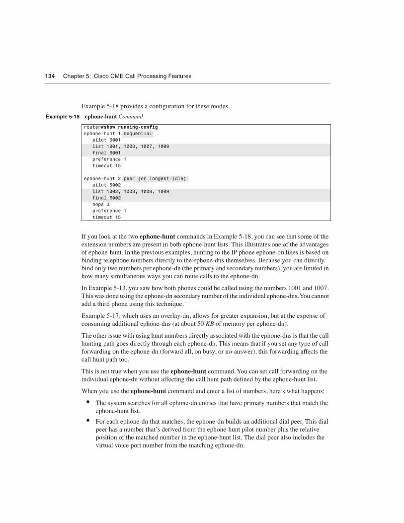
Example 5-18 provides a configuration for these modes.
If you look at the two ephone-hunt commands in Example 5-18, you can see that some of the extension numbers are present in both ephone-hunt lists. This illustrates one of the advantages of ephone-hunt. In the previous examples, hunting to the IP phone ephone-dn lines is based on binding telephone numbers directly to the ephone-dns themselves. Because you can directly bind only two numbers per ephone-dn (the primary and secondary numbers), you are limited in how many simultaneous ways you can route calls to the ephone-dn.
In Example 5-13, you saw how both phones could be called using the numbers 1001 and 1007. This was done using the ephone-dn secondary number of the individual ephone-dns. You cannot add a third phone using this technique.
Example 5-17, which uses an overlay-dn, allows for greater expansion, but at the expense of consuming additional ephone-dns (at about 50 KB of memory per ephone-dn).
The other issue with using hunt numbers directly associated with the ephone-dns is that the call hunting path goes directly through each ephone-dn. This means that if you set any type of call forwarding on the ephone-dn (forward all, on busy, or no-answer), this forwarding affects the call hunt path too.
This is not true when you use the ephone-hunt command. You can set call forwarding on the individual ephone-dn without affecting the call hunt path defined by the ephone-hunt list.
When you use the ephone-hunt command and enter a list of numbers, here’s what happens:
• The system searches for all ephone-dn entries that have primary numbers that match the ephone-hunt list.
• For each ephone-dn that matches, the ephone-dn builds an additional dial peer. This dial peer has a number that’s derived from the ephone-hunt pilot number plus the relative position of the matched number in the ephone-hunt list. The dial peer also includes the virtual voice port number from the matching ephone-dn.
Example 5-18 ephone-hunt Command
router#show running-configephone-hunt 1 sequential pilot 5001 list 1001, 1003, 1007, 1008 final 6001 preference 1 timeout 15
ephone-hunt 2 peer (or longest-idle) pilot 5002 list 1002, 1003, 1008, 1009 final 6002 hops 3 preference 1 timeout 15

Implementing Shared Lines and Hunt Groups 135
When you configure call forwarding under ephone-dn, the call forwarding information is inserted into the dial peers that are directly bound to the ephone-dn. The call forwarding information is not included in the dial peers created by the ephone-hunt command.
You also notice that the ephone-hunt command lets you set a preference value. As you might expect, this is a dial peer preference. The dial peer preference is inserted into the dial peer that is created by ephone-hunt to match the ephone-hunt pilot number.
For the ephone-hunt configuration examples shown, at least five dial peers are created. One dial peer is created for the pilot number. One dial peer is created for each ephone-dn that is found that matches one of the numbers in the list. If multiple ephone-dns match the individual numbers in the list, each of those ephone-dns causes the creation of an additional dial peer.
Here is a description of what you see for ephone-hunt 1 in Example 5-18:
• The pilot number creates a dial peer with destination pattern 5001. This dial peer has call forward all set to the first dial peer in the hunt list.
• The first member of the list creates a dial peer with destination pattern A5001A0001. This dial peer contains the virtual voice port number of the ephone-dn that has 1001 as its primary number. This dial peer has call-forward busy and call-forward no-answer set to the next ephone-hunt dial peer. The call-forward timeout value is set by the timeout subcommand under ephone-hunt.
• The second member of the list creates a dial peer with destination pattern A5001A0002. This dial peer contains the virtual voice port number of the ephone-dn that has 1003 as its primary number. This dial peer has call-forward busy and call-forward no-answer set to the next ephone-hunt dial peer.
• The third member of the list creates a dial peer with destination pattern A5001A0003. This dial peer contains the virtual voice port number of the ephone-dn that has 1007 as its primary number. This dial peer has call-forward busy and call-forward no-answer set to the next ephone-hunt dial peer.
• The fourth and final member of the list creates a dial peer with destination pattern A5001A0004. This dial peer contains the virtual voice port number of the ephone-dn that has 1008 as its primary number. This dial peer has call-forward busy and call-forward no-answer set to the number defined as the final destination for the ephone-hunt.
The digit A in the destination pattern is the DTMF digit A from the extended set of DTMF digits A to D. The digits A to D are routable digits within the Cisco IOS voice infrastructure software and can be used just like the digits 0 to 9 and *. The digit # is often used as a dial digit string terminator.
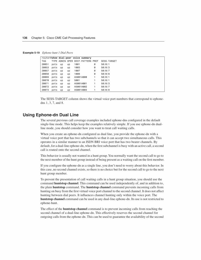
You can view all the dial peers created by the ephone-hunt command using the Cisco IOS command show dial-peer voice summary. Example 5-19 shows the dial peers associated with ephone-hunt 1 in Example 5-18.
136 Chapter 5: Cisco CME Call Processing Features
The SESS-TARGET column shows the virtual voice port numbers that correspond to ephone-dns 1, 3, 7, and 8.
Using Ephone-dn Dual LineThe several previous call coverage examples included ephone-dns configured in the default single-line mode. This helps keep the examples relatively simple. If you use ephone-dn dual-line mode, you should consider how you want to treat call waiting calls.
When you create an ephone-dn configured as dual line, you provide the ephone-dn with a virtual voice port that has two subchannels so that it can accept two simultaneous calls. This operates in a similar manner to an ISDN BRI voice port that has two bearer channels. By default, for a dual-line ephone-dn, when the first subchannel is busy with an active call, a second call is routed onto the second channel.
This behavior is usually not wanted in a hunt group. You normally want the second call to go to the next member of the hunt group instead of being present as a waiting call on the first member.
If you configure the ephone-dn as a single line, you don’t need to worry about this behavior. In this case, no second channel exists, so there is no choice but for the second call to go to the next hunt group member.
To prevent the presentation of call waiting calls in a hunt group situation, you should use the command huntstop channel. This command can be used independently of, and in addition to, the plain huntstop command. The huntstop channel command prevents incoming calls from hunting on busy from the first virtual voice port channel to the second channel. It does not affect hunting between dial peers. It influences channel hunting only within the voice port. The huntstop channel command can be used in any dual-line ephone-dn. Its use is not restricted to ephone-hunt.
The effect of the huntstop channel command is to prevent incoming calls from reaching the second channel of a dual-line ephone-dn. This effectively reserves the second channel for outgoing calls from the ephone-dn. This can be used to guarantee the availability of the second
Example 5-19 Ephone-hunt 1 Dial Peers
router#show dial-peer voice summaryTAG TYPE ADMIN OPER DEST-PATTERN PREF SESS-TARGET20051 pots up up 1001 0 50/0/120053 pots up up 1003 0 50/0/320057 pots up up 1007 0 50/0/720058 pots up up 1008 0 50/0/820069 pots up up A5001A000 1 50/0/120070 pots up up 5001 1 50/0/120071 pots up up A5001A001 1 50/0/320072 pots up up A5001A002 1 50/0/720073 pots up up A5001A003 1 50/0/8
Implementing Shared Lines and Hunt Groups 137
channel to support the second call instance required for features such as three-party conference and call transfer with consultation.
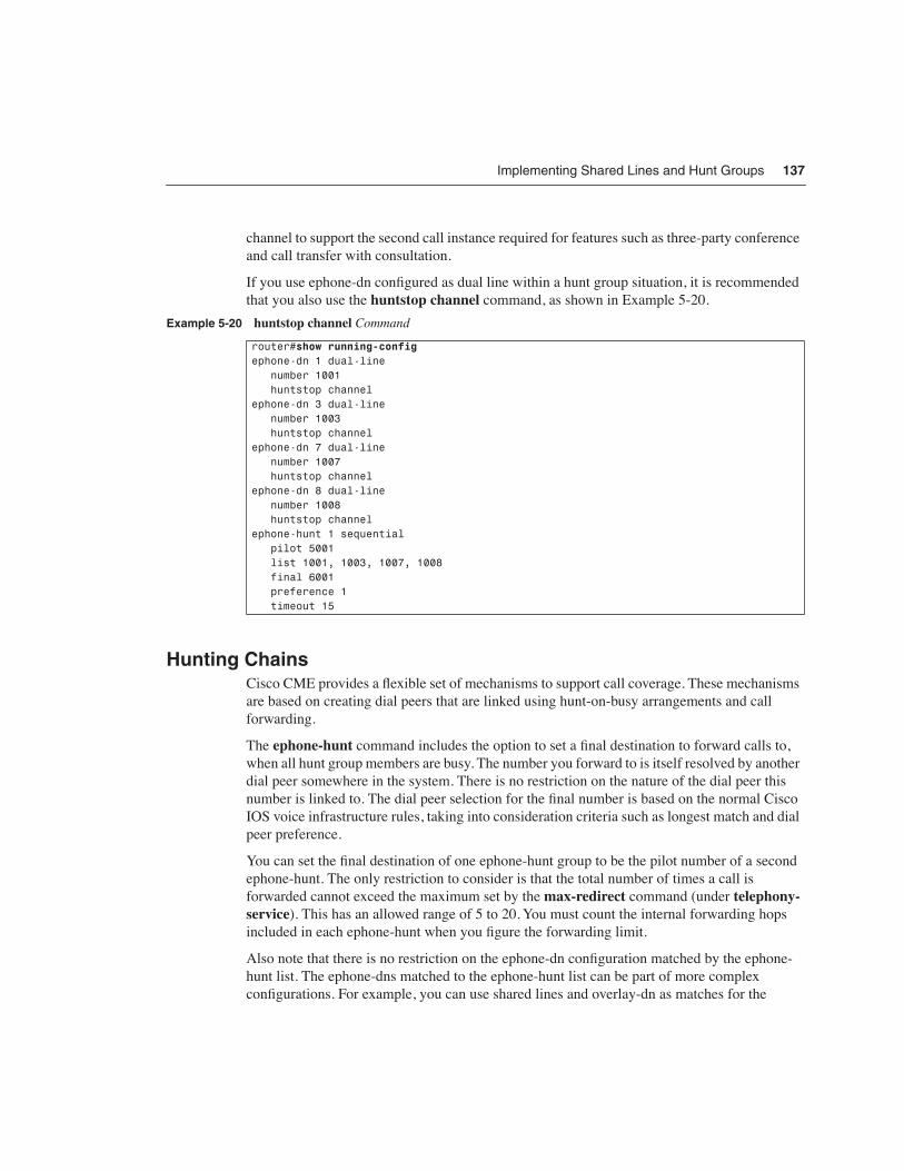
If you use ephone-dn configured as dual line within a hunt group situation, it is recommended that you also use the huntstop channel command, as shown in Example 5-20.
Hunting ChainsCisco CME provides a flexible set of mechanisms to support call coverage. These mechanisms are based on creating dial peers that are linked using hunt-on-busy arrangements and call forwarding.
The ephone-hunt command includes the option to set a final destination to forward calls to, when all hunt group members are busy. The number you forward to is itself resolved by another dial peer somewhere in the system. There is no restriction on the nature of the dial peer this number is linked to. The dial peer selection for the final number is based on the normal Cisco IOS voice infrastructure rules, taking into consideration criteria such as longest match and dial peer preference.
You can set the final destination of one ephone-hunt group to be the pilot number of a second ephone-hunt. The only restriction to consider is that the total number of times a call is forwarded cannot exceed the maximum set by the max-redirect command (under telephony-service). This has an allowed range of 5 to 20. You must count the internal forwarding hops included in each ephone-hunt when you figure the forwarding limit.
Also note that there is no restriction on the ephone-dn configuration matched by the ephone-hunt list. The ephone-dns matched to the ephone-hunt list can be part of more complex configurations. For example, you can use shared lines and overlay-dn as matches for the
Example 5-20 huntstop channel Command
router#show running-configephone-dn 1 dual-line number 1001 huntstop channelephone-dn 3 dual-line number 1003 huntstop channelephone-dn 7 dual-line number 1007 huntstop channelephone-dn 8 dual-line number 1008 huntstop channelephone-hunt 1 sequential pilot 5001 list 1001, 1003, 1007, 1008 final 6001 preference 1 timeout 15
138 Chapter 5: Cisco CME Call Processing Features
ephone-hunt list. This lets you create some very complex call coverage arrangements, including arrangements that perform sequential-parallel hunting, in which different groups of phones ring in a defined linear or circular sequence.
One final point here is that setting call-forward all for an ephone-dn that is part of a hunt group does not break the hunt group forwarding sequence. This is because the call-forward all is applied only to the ephone-dn’s main dial peer, not to the subsidiary dial peers that are generated by the ephone-hunt command. To temporarily remove a phone from a hunt group, you simply put the phone into Do-Not-Disturb mode (the Cisco CME 3.2 DND feature).
Immediate Diversion of Calls to Voice MailIn earlier sections, you saw the use of the call-forward busy and call-forward noan (no answer) commands to control call forwarding of calls for busy and no-answer extensions. In many cases, the number the call is forwarded to is the pilot number for a voice mail system.
Cisco CME 3.2 and later allows the person receiving a call to cause the incoming call to be forwarded immediately without having to wait for the no-answer timer to expire. (This is applicable only on Cisco IP phones that have softkeys.) When an incoming call is presented, the phone user sees two softkeys: answer and DND (Do Not Disturb). If the user’s phone has call-forward no-answer configured, pressing the DND softkey causes the incoming call to be forwarded immediately to the number configured for call-forward no-answer (typically the voice mail number).
If no call-forward no-answer is configured for the extension, pressing the DND key simply mutes the phone’s ringer until the call is cancelled (by the caller hanging up). The ringer mute DND action is temporary and applies only to the current call when used in the manner described. The phone can also be placed in a permanent muted ringer state by pressing the DND softkey while the phone is in the idle state. This allows the phone user to screen incoming calls, because the phone display is still active and shows the caller ID for incoming calls. If a phone user wants to avoid all incoming calls, you can use the cfwdall (call forward all) softkey to set up unconditional forwarding of incoming calls to voice mail (or another extension). In this case, there is no indication of incoming calls on the user’s phone.
Call Coverage SummaryThis section has described a wide array of techniques for providing call coverage solutions. You can use the dial peer hunting mechanisms provided by the Cisco IOS voice infrastructure features. You can use call forwarding. You can use the ephone-hunt mechanism. You also have the option of using overlay-dn. You may combine several of these options to produce complex call coverage paths.

Creating an Intercom 139
Creating an IntercomCisco CME supports single-button push-to-talk and push-to-respond intercom lines. You can create an intercom arrangement between any two (multiline) IP phones that support speakerphone operation. You can even operate an intercom across a VoIP connection using either SIP or H.323. Cisco CME’s intercom function is built using two functions:
• Autodial at the initiating end of the intercom
• Autoanswer-with-mute at the receiving end
To create an intercom you assign a line button on each of the two phones to operate as an intercom line. Pressing the intercom line button selects the line and triggers the autodial function toward the second phone. The receiving phone receives the incoming intercom call on its intercom line. This line autoanswers the call and activates the phone in speakerphone mode and sounds a beep. It also forces the speakerphone to mute to protect the privacy of the intercom recipient. The audio path is open from the initiator to the receiver. To respond to the intercom, the recipient simply presses the mute button to unmute the audio path back to the originator.
The intercom CommandExample 5-21 shows a configuration of an intercom between two IP phones.
Example 5-21 shows two phones. John’s phone has button 1 as his primary extension line. Button 2 on John’s phone is an intercom line. This line is set to autodial Jane’s phone using the number 1111. The button is labeled “Jane” to show that pressing the button intercoms to Jane.
Example 5-21 Intercom Lines
router#show running-configephone-dn 1 dual-line number 1001 name John Smithephone-dn 2 dual-line number 1002 name Jane Smithephone-dn 3 number 1111 intercom 1112 label Janeephone-dn 4 number 1112 intercom 1111 label Johnephone 12 mac-address 000d.1234.0efc button 1:1 2:3ephone 15 mac-address 000d.5678.0dcf button 1:2 2:4

140 Chapter 5: Cisco CME Call Processing Features
NOTE The intercom lines are configured in the default single-line mode.
Jane’s phone is configured to match to John’s phone. Button 1 on Jane’s phone is her primary line. Button 2 is set to autodial John’s phone and shows the label “John” next to the button. The default configuration for an intercom line is that it autoanswers with mute for any incoming call. Autoanswer can be disabled if desired using the no-auto-answer command option.
Example 5-21 shows a fully symmetric two-way intercom arrangement. John can intercom to Jane, and Jane can intercom to John.
Individual phones may have more than one intercom. The maximum number of intercoms per phone is limited only by the number of available buttons. In general, using intercoms on single-line phones such as the Cisco 7910, 7905, and 7912 is not recommended. These phones do not have a built-in (hands-free) microphone and, therefore, cannot be unmuted without lifting the phone’s handset.
Many-to-One IntercomIn the previous example you saw that an intercom line autoanswers any incoming call. The incoming intercom does not perform any type of cross-check on the calling party to ensure that it matches the outgoing intercom destination. This arrangement lets you create a many-to-one intercom, which is useful when you have a single shared assistant working for multiple executives, as shown in Example 5-22.
Example 5-22 Shared-Line Intercom
router#show running-configephone-dn 1 dual-line number 2101 name Executive1ephone-dn 2 dual-line number 2102 name Executive2ephone-dn 3 dual-line number 2103 name Executive3ephone-dn 4 dual-line number 2201 name Assistantephone-dn 5 number 1110 intercom 1110 label Intercomephone-dn 6 number 1111 intercom 1110 label Intercomephone-dn 7 number 1112

Creating an Intercom 141
In Example 5-22, ephones 12 to 14 belong to the three executives 2101 to 2103. The fourth phone, ephone 15, belongs to the assistant. Each of the four phones has its primary line associated with button 1. The second buttons on the three executive phones are configured to intercom to the assistant’s intercom line. This configuration provides a many-to-one intercom. Any of the executives can press the button 2 intercom on his or her phone to talk to the assistant. Of course, only one intercom conversation can exist at one time.
Note that the assistant’s intercom (ephone-dn 5) is set to autodial itself. It is not possible to create a one-to-many intercom path. The assistant’s phone could also be configured to autodial one of the executives.
One-Way IntercomsIn the previous many-to-one intercom example, you saw that the assistant’s intercom is configured as a one-way or receive-only intercom. This is done by configuring the intercom line to autodial itself. When the assistant presses the intercom button, he or she hears busy tone.
You can use this technique to configure a one-way intercom even in a simple one-to-one intercom arrangement. A better configuration for a one-way, one-to-one intercom is to use the noautoanswer command option, as shown in Example 5-23.
intercom 1110 label Intercomephone-dn 8 number 1113 intercom 1110 label Intercomephone 12 mac-address 000d.1234.0efc button 1:1 2:6ephone 13 mac-address 000d.5678.0dcf button 1:2 2:7ephone 14 mac-address 000d.4321.0ef7 button 1:3 2:8ephone 15 mac-address 000d.4132.f7e4 button 1:4 2:5
Example 5-23 One-to-One Intercom
router#show running-configephone-dn 1 dual-line number 2101 name Executiveephone-dn 4 dual-line number 2201 name Assistantephone-dn 5
Example 5-22 Shared-Line Intercom (Continued)
continues

142 Chapter 5: Cisco CME Call Processing Features
With this arrangement, you still have a direct one-to-one dedicated line between the executive and the assistant. Only the assistant’s phone autoanswers incoming calls presented to its intercom line. If the assistant presses the intercom line, the phone still autodials the executive’s intercom line. The executive’s phone simply rings as for a normal call.
Dialable and Private IntercomsAll the previous intercom examples in this chapter show intercoms configured with ordinary extension numbers. This means that you can dial into the intercom lines from any phone, not just the phones configured for intercom. You can even put the intercom numbers into the Cisco CME system directory or speed-dial lists.
You can make the intercom more restrictive by using the extended DTMF digits A–D as part of the intercom phone number. Because IP phones do not have the A–D DTMF digit keys available on their keypads, if the phone number includes A–D digits, it cannot be dialed from an ordinary phone.
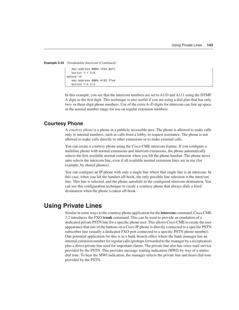
Example 5-24 shows how to restrict intercom numbers so that they cannot be dialed from an ordinary telephone.
number 1110 intercom 1111 label Intercomephone-dn 6 number 1111 intercom 1110 label Intercom no-auto-answerephone 12 mac-address 000d.1234.0efc button 1:1 2:6ephone 15 mac-address 000d.4132.f7e4 button 1:4 2:5
Example 5-24 Nondialable Intercom
router#show running-configephone-dn 1 dual-line number 2101 name Executiveephone-dn 4 dual-line number 2201 name Assistantephone-dn 5 number A110 intercom A111 label Intercomephone-dn 6 number A111 intercom A110 label Intercomephone 12
Example 5-23 One-to-One Intercom (Continued)
Using Private Lines 143
In this example, you see that the intercom numbers are set to A110 and A111 using the DTMF A digit as the first digit. This technique is also useful if you are using a dial plan that has only two- or three-digit phone numbers. Use of the extra A–D digits for intercom can free up space in the normal number range for use on regular extension numbers.
Courtesy PhoneA courtesy phone is a phone in a publicly accessible area. The phone is allowed to make calls only to internal numbers, such as calls from a lobby, to request assistance. The phone is not allowed to make calls directly to other extensions or to make external calls.
You can create a courtesy phone using the Cisco CME intercom feature. If you configure a multiline phone with normal extensions and intercom extensions, the phone automatically selects the first available normal extension when you lift the phone handset. The phone never auto selects the intercom line, even if all available normal extension lines are in use (for example, by shared phones).
You can configure an IP phone with only a single line where that single line is an intercom. In this case, when you lift the handset off-hook, the only possible line selection is the intercom line. This line is selected, and the phone autodials to the configured intercom destination. You can use this configuration technique to create a courtesy phone that always dials a fixed destination when the phone is taken off-hook.
Using Private LinesSimilar in some ways to the courtesy phone application for the intercom command, Cisco CME 3.2 introduces the FXO trunk command. This can be used to provide an emulation of a dedicated private PSTN line for a specific phone user. This allows Cisco CME to create the user appearance that one of the buttons on a Cisco IP phone is directly connected to a specific PSTN subscriber line (usually a dedicated FXO port connected to a specific PSTN phone number). One potential application for this is in a bank branch office where the bank manager has an internal extension number for regular calls (perhaps forwarded to the manager by a receptionist) plus a direct private line used for important clients. The private line also has voice mail service provided by the PSTN. This provides message waiting indication (MWI) by way of a stutter dial tone. To hear the MWI indication, the manager selects the private line and hears dial tone provided by the PSTN.
mac-address 000d.1234.0efc button 1:1 2:6ephone 15 mac-address 000d.4132.f7e4 button 1:4 2:5
Example 5-24 Nondialable Intercom (Continued)

144 Chapter 5: Cisco CME Call Processing Features
Example 5-25 shows how the trunk command is used to create a private line on an IP phone.
Example 5-25 shows ephone 1 configured with two lines. Button 1 is a normal extension (number 1010) using ephone-dn 10. Button 2 is the private line using ephone-dn 11. Incoming PSTN calls on FXO port 1/0/0 are routed directly to ephone 11 (extension number 1082) by the connection plar-opx 1082 command that is shown under voice-port 1/0/0.
Outgoing calls on the private line are routed to voice port 1/0/0 by the trunk 82 command within ephone-dn 11. This causes all calls dialed on ephone-dn 11 to have the digits 82 prefixed to the dialed number. The 82 prefix causes the calls to match to the destination-pattern 82 in dial peer 82 and, thus selects voice port 1/0/0 for the outbound call.
When the phone user dials the number, such as 555-0510, the trunk command prefixes the digits 82 to create the number 825550510. The leading digits 82 match the destination pattern for the voice port dial peer. The leading 82 digits are stripped off, and the remaining digits, 5550510, are forwarded to the PSTN line. Note that in some cases, you may need to adjust the time delay before the digits are passed to the PSTN line to avoid their being sent before the PSTN line is ready to accept them. You can do this using the prefix command (under the POTS dial peer) and using commas to insert 1-second units of delay. For example, the command prefix ,, inserts 2 seconds of delay.
The appearance that the phone button is directly connected to the FXO port’s PSTN line is obtained by means of the one-to-one association that’s created by the combination of the connection plar-opx binding of the FXO port to the ephone-dn, plus the trunk binding of the ephone-dn back to the FXO port. Because of this arrangement, whenever the FXO port is in use, it follows that the ephone-dn is also in use. Therefore, the ephone-dn’s status reflects the FXO port’s status.
To maintain this direct one-to-one binding, call operations that could break the one-to-one binding are disabled by the trunk command. This means that functions such as call transfer and call forwarding are not supported when the trunk configuration is used. However, functions
Example 5-25 FXO trunk Command
router#show running-configvoice-port 1/0/0 connection plar-opx 1082dial-peer voice 82 pots destination-pattern 82 port 1/0/0ephone-dn 10 number 1010 name managerephone-dn 11 number 1082 name private-line trunk 82ephone 1 button 1:10 2:11

Paging 145
such as call hold and conference are supported, including the ability to join two ephone-dn trunk lines in a three-party conference.
You can use the trunk command and connection plar-opx command independent of each other. For example, you can create other private line-like call behaviors where incoming calls are directly routed to a specific extension using the connection plar-opx command but outgoing calls use the common “Dial 9 for an outside line” approach.
PagingYou can set up a Cisco CME system to provide audio paging using the speakers of your IP phones to broadcast the paging audio output. This feature works in conjunction with IP phones that have a speakerphone mode. Only IP phones that are idle are used to output paging audio. IP phones can still be used to make or receive calls during paging. When the phone is used, it simply drops out of the page.
You can create paging groups or zones that output paging audio only on specific groups of IP phones. You can also combine multiple paging groups to output audio paging to multiple paging groups at the same time.
Using your IP phones to provide an audio paging system can save the additional cost of installing a separate overhead audio paging system. If you already have a conventional overhead audio paging system, you can also use this with Cisco CME. You simply need an available physical voice port on your router that can connect to the paging system. Ear and mouth (E&M) voice ports are the easiest to use because they do not usually require external adapter hardware. Because E&M ports usually come in pairs, you can also use the second E&M port as an input to connect to an external music on hold audio source.
The following sections describe how you can use the Cisco CME paging features.
Paging GroupsTo configure an IP phone-based paging group, you first set up an ephone-dn entry in your system to act as the pilot number for the paging group. Like most of the special-purpose ephone-dns you create for your Cisco CME system, the paging ephone-dn is not directly bound to any of your IP phones. You don’t use this ephone-dn in a button command.
The paging group pilot number is the number you dial from a phone to output audio to the paging group. A sample configuration is shown in Example 5-26. Note that you can dial into a paging group from any phone, including via a VoIP connection. You can also set up speed-dial buttons on your IP phones to dial into the paging number for one-button push-to-page operation.

146 Chapter 5: Cisco CME Call Processing Features
The paging-dn is set up with a pilot number of 6112. When you make a call to 6112, it is answered by the paging-dn. The audio stream from your phone to the paging-dn is broadcast to all the phones in the paging group for ephone-dn 14 using IP Multicast on address 239.1.1.1 and port 2000.
As soon as you have created your paging-dn, you then create a group of IP phones to include in your paging group, as shown in Example 5-27. You do this using the paging-dn command within the ephone command mode. Set the paging-dn command in the ephone command mode to select the tag number of the ephone-dn that you configured as a paging-dn (14 in this example).
With the configuration shown in Example 5-27, when you dial the number 6112 from any phone, the speakerphone on ephones 12 and 15 activates, provided that the phones are idle and the audio from the call is IP Multicast to both phones and output via the speakerphone.
There is no limit on the number of IP phones that can be included in a paging group. There is no specific limit on the number of paging-dns and corresponding paging groups you can create. Each paging group consumes one of the finite number of ephone-dns in your Cisco CME system. You can create individual paging groups for each department in your organization—for example, sales, accounts, and service.
Each IP phone can belong directly to only a single paging group. You can enter only one paging-dn configuration per ephone.
Example 5-26 Paging Pilot Number Configuration
router#show running-configephone-dn 14 number 6112 name Sales paging ip 239.1.1.1 port 2000
Example 5-27 Paging on IP Phones
router#show running-configephone 12 mac-address 000d.1234.0efc button 1:1 2:6 paging-dn 14ephone 15 mac-address 000d.4132.f7e4 button 1:4 2:5 paging-dn 14

Paging 147
Combining Paging GroupsAfter you have created the individual paging groups, you can combine up to ten paging groups. You use the paging group command followed by a list of the paging-dn tag numbers you want to include in the group. Example 5-28 shows how two paging groups are combined.
In Example 5-28, you can see that paging-dn in ephone-dn 14 creates the paging group for the sales department with pilot number 6112. This group contains ephones 12 and 15. Ephone-dn 16 creates the paging group for the accounts department with pilot number 6113. This group contains ephones 19 and 21.
The combined paging group is created by ephone-dn 17. It uses the pilot number 6120. This combines the paging groups of paging-dn ephone-dns 14 and 16 by listing the ephone-dn tag values after the paging group command.
When you call the pilot number 6120 for the combined group, all four of the IP phones are used to output the paging audio. Note that each paging-dn uses a different multicast IP address. Using different IP Multicast addresses for each paging group allows you to have simultaneous paging to different groups. In this example, it allows you to have unrelated paging to the sales and accounts department at the same time.
Example 5-28 Using the paging group Command
router#show running-configephone-dn 14 number 6112 name Sales paging ip 239.1.1.2 port 2000ephone-dn 16 number 6113 name Accounts paging ip 239.1.1.3 port 2000ephone-dn 17 number 6120 name Sales&Acccounts paging ip 239.1.1.20 port 2000 paging group 14,16ephone 12 mac-address 000d.1234.0efc button 1:1 paging-dn 14ephone 15 mac-address 000d.4132.f7e4 button 1:2 paging-dn 14ephone 19 mac-address 000d.5678.13f4 button 1:24 paging-dn 15ephone 21 mac-address 000d.8765.23e5 button 1:27 paging-dn 15

148 Chapter 5: Cisco CME Call Processing Features
Multicast Routing for PagingAn IP Multicast address is any IP address in the range 224.0.0.0 to 239.255.255.255. However, you cannot use the 224.x.x.x address range, because it is typically reserved, and most Cisco IP phones do not accept IP Multicast streams in this range. For most normal use, the IP Multicast address range 239.x.x.x is recommended. This address range is locally scoped and is not routed outside your network. The details of IP Multicast routing are more formally defined in RFC 1112, Host Extensions for IP Multicasting.
For simple Cisco CME systems where all your IP phones are connected to the same local LAN, you do not need to configure your router(s) for multicast routing to use the Cisco CME paging mechanism. The Cisco CME software takes care of directing multicast packets to the appropriate local Ethernet interface(s) that connect to your IP phones. Because the IP phones maintain SCCP communication with CME over TCP/IP, the Cisco CME router has direct knowledge of the locations of the phones and, therefore, does not need to rely on multicast routing mechanisms to distribute IP Multicast packets. If you have a small number of IP phones that are not directly connected to the Cisco CME router local LAN, you can still include these in paging by configuring individual IP phones to use unicast paging. Add the unicast option to the phone’s paging configuration under the ephone command, as shown in Example 5-29.
You can have up to ten unique output destinations in a paging audio IP stream, where a destination is either a router interface (Ethernet port) or a phone’s unique IP (unicast) address. This means that if the multicast IP audio stream is sent out on only a single Ethernet port for the benefit of the majority of your phones, you may additionally include up to nine nonmulticast phone destinations using individual unicast paging.
For more complex local networks that involve multiple routing hops, you most likely need to configure multicast routing on the routers that are located between the Cisco CME router and your IP phones.
Implementing OverlaysThe Cisco CME overlay feature provides a way to work around the physical button limits on your IP phones. Instead of a normal one-line-to-one-button mapping arrangement, you can map up to ten lines or ephone-dns to the same physical phone button. This allows you to use the same phone button to answer incoming calls on any of the up to ten ephone-dns associated with the button.
Example 5-29 Unicast Paging
router#show running-configephone 12 mac-address 000d.1234.0efc button 1:1 paging-dn 14 unicast
Implementing Overlays 149
NOTE Although you can map ten ephone-dns to the same button, you can work with and see only one ephone-dn at a time.
Earlier, you saw one usage (in Example 5-17) for overlay-dns, where it allowed access to multiple instances of ephone-dns that have the same telephone number. See Figure 5-2 earlier in this chapter.
The Purpose of an Overlay-dnAn overlay-dn associates or binds from two to ten ephone-dn IP phone lines onto a single IP phone button (even on single-line IP phones). You can use separate overlay-dn arrangements on each separate IP phone button. Each IP phone can use an independent set of ephone-dns for overlay for each of the phone’s buttons.
An overlay-dn acts as a multiplexor. It dynamically selects the most appropriate ephone-dn to present on an IP phone button from within the configured overlay-dn set. When you receive incoming calls, the first ringing ephone-dn in the overlay set is presented. When you make an outgoing call, the first idle ephone-dn in the overlay set is selected.
You can configure the ephone-dns used in an overlay set as either single line or dual line. However, all the ephone-dns in the same overlay set must be of the same type (single or dual line).
Using Overlay to Overcome Phone Button Count LimitsThe simplest use of overlay-dn is to overcome the limited number of physical buttons available on an IP phone. In a simple Key System case where you have four incoming PSTN trunk lines and four IP phones, you can make each line available on all phones simply by using one button per line. You can do this using a Cisco 7960 IP Phone, which has six buttons. With this arrangement, you can answer any of the four incoming lines on any of the four IP phones.
However, you cannot use this simple one-button-to-one-line mapping if you want to have ten incoming PSTN lines and ten IP phones (assuming a six-line Cisco 7960 IP Phone). There simply aren’t enough line buttons to do this (unless you add a Cisco 7914 IP Phone Expansion Module to your Cisco 7960 IP Phones).
Example 5-30 shows how you can map ten incoming PSTN lines to a single button on an IP phone.

150 Chapter 5: Cisco CME Call Processing Features
Example 5-30 Overlay-dn Configuration
router#show running-configephone-dn 101 number 4085550101 no huntstopephone-dn 102 number 4085550101 preference 1 no huntstopephone-dn 103 number 4085550101 preference 2 no huntstopephone-dn 104 number 4085550101 preference 3 no huntstopephone-dn 105 number 4085550101 preference 4 no huntstopephone-dn 106 number 4085550101 preference 5 no huntstopephone-dn 107 number 4085550101 preference 6 no huntstopephone-dn 108 number 4085550101 preference 7 no huntstopephone-dn 109 number 4085550101 preference 8 no huntstopephone-dn 110 number 4085550101 preference 9ephone 1 mac-address 000d.1234.ecfd button 1o101,102,103,104,105,106,107,108,109,110ephone 2 mac-address 000d.4321.a6b7 button 1o101,102,103,104,105,106,107,108,109,110ephone 3 mac-address 000d.5678.b923 button 1o101,102,103,104,105,106,107,108,109,110

Implementing Overlays 151
The key to this configuration is the o separator used in the button command in place of the normal : separator character. In this configuration example, the preference and huntstop commands are used to control the order of selection of the incoming lines (in preference order from 101 to 110).
This configuration allows any incoming call to be answered on any of the IP phones. The example shows only the first three IP phones. There is no specific limit on the number of phones that can share the lines as shown. But, in general, you want to limit the number of phones so as not to exceed the number of lines. If there are more phones than lines, some phones can’t access any lines if they are all in use.
Using Overlay with IntercomYou can include ephone-dns configured for intercom within an overlay set. In general, you would do this only for one-way intercoms where the phone with the overlay intercom is not expected to initiate an outgoing intercom call. This allows you to attach an incoming-only intercom to an IP phone without using up one of the phone’s buttons. If the intercom is used as incoming only, there is no need to assign a phone button to select the intercom. One example of incoming-only intercom is the many-to-one intercom case discussed earlier.
Overlays and Shared LinesIn the section “Using Shared Lines for Call Coverage,” you saw how a call can be put on hold on one phone by pressing the hold softkey and then picked up by pressing the resume softkey on a second phone that shares the line.
This form of shared-line direct call pickup is unavailable in the case of lines shared by a phone in an overlay set. As soon as an ephone-dn is dynamically associated to a specific phone using an overlay, the ephone-dn is no longer accessible on other phones that share the ephone-dn using overlay. It is available on phones that directly share the line using a simple nonoverlay button assignment (for example, by using the : separator, as in button 1:tag).
You can still move calls between phones in this arrangement by using the pickup softkey, provided that you carefully number the ephone-dns within the overlay set so that they can be uniquely selected. Example 5-31 uses a simplified form of the previous configuration.
Example 5-31 Simplified Overlay-dn Configuration
router#show running-configephone-dn 101 label 4085550101 number 101 secondary 4085550101 no huntstopephone-dn 102 number 102 secondary 4085550101 preference 1 no huntstop
continues
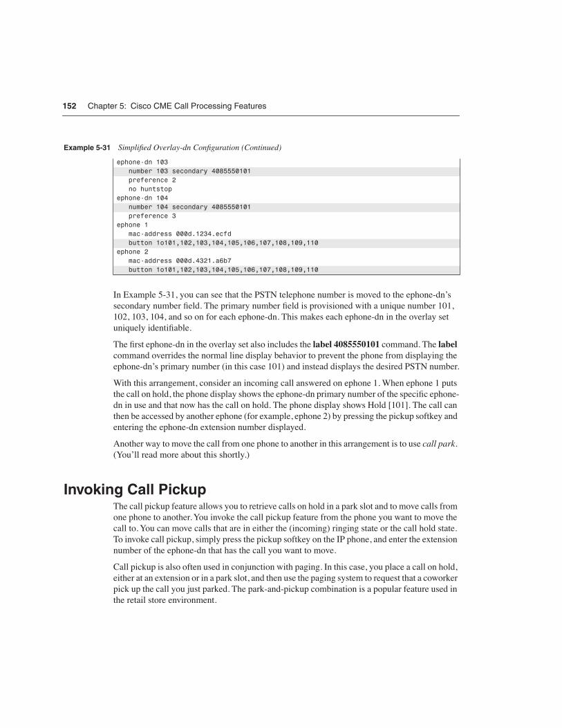
152 Chapter 5: Cisco CME Call Processing Features
In Example 5-31, you can see that the PSTN telephone number is moved to the ephone-dn’s secondary number field. The primary number field is provisioned with a unique number 101, 102, 103, 104, and so on for each ephone-dn. This makes each ephone-dn in the overlay set uniquely identifiable.
The first ephone-dn in the overlay set also includes the label 4085550101 command. The label command overrides the normal line display behavior to prevent the phone from displaying the ephone-dn’s primary number (in this case 101) and instead displays the desired PSTN number.
With this arrangement, consider an incoming call answered on ephone 1. When ephone 1 puts the call on hold, the phone display shows the ephone-dn primary number of the specific ephone-dn in use and that now has the call on hold. The phone display shows Hold [101]. The call can then be accessed by another ephone (for example, ephone 2) by pressing the pickup softkey and entering the ephone-dn extension number displayed.
Another way to move the call from one phone to another in this arrangement is to use call park. (You’ll read more about this shortly.)
Invoking Call PickupThe call pickup feature allows you to retrieve calls on hold in a park slot and to move calls from one phone to another. You invoke the call pickup feature from the phone you want to move the call to. You can move calls that are in either the (incoming) ringing state or the call hold state. To invoke call pickup, simply press the pickup softkey on the IP phone, and enter the extension number of the ephone-dn that has the call you want to move.
Call pickup is also often used in conjunction with paging. In this case, you place a call on hold, either at an extension or in a park slot, and then use the paging system to request that a coworker pick up the call you just parked. The park-and-pickup combination is a popular feature used in the retail store environment.
ephone-dn 103 number 103 secondary 4085550101 preference 2 no huntstopephone-dn 104 number 104 secondary 4085550101 preference 3ephone 1 mac-address 000d.1234.ecfd button 1o101,102,103,104,105,106,107,108,109,110ephone 2 mac-address 000d.4321.a6b7 button 1o101,102,103,104,105,106,107,108,109,110
Example 5-31 Simplified Overlay-dn Configuration (Continued)

Invoking Call Pickup 153
Pickup of a Ringing ExtensionYou can use the pickup softkey to move a call on a ringing extension on another phone to your phone. When you invoke call pickup, the Cisco CME system triggers a call forward from the phone with the ringing extension to your phone. Because the call pickup for a ringing extension uses the call forwarding mechanism, the general restrictions and considerations that apply to forwarded calls (forward on no-answer) also apply to calls for pickup on ringing. This means that the max-redirects limit set under telephony-service may affect the call pickup feature.
Pickup of a Call on HoldYou can use the pickup softkey to move a call that is on hold at an extension on another phone and move it to your phone. When you invoke call pickup, the Cisco CME system triggers a blind call transfer from the phone with the on-hold call to your phone. Because the call pickup for an on-hold call uses the call transfer mechanism, the general restrictions and considerations that apply to transferring calls also apply to calls for pickup on hold.
Pickup GroupsThe group pickup feature operates in a manner similar to simple extension pickup. To use the group pickup feature, press the gpickup softkey and enter a pickup group number. You can use the group pickup feature to pick up any ringing call in a designated group of phones. You cannot use the group pickup feature to pick up calls that are on hold.
You can assign each phone in your Cisco CME system to a pickup group. You can have any number of pickup groups in your Cisco CME system.
If you create only a single pickup group in your Cisco CME system, you can pick up calls from within the single pickup group by simply pressing the gpickup softkey. If your Cisco CME system has only a single pickup group, there is no need to enter a pickup group number.
If you have more than one pickup group, you can pick up calls from within a phone’s local pickup group by pressing the gpickup softkey followed by the star (*) key. This provides a shortcut instead of requiring you to enter the phone’s own pickup group number.
To assign a phone to a specific pickup group, use the pickup-group command within the ephone configuration command mode, as shown in Example 5-32.
Example 5-32 Pickup Group Configuration
router#show running-configephone 1 mac-address 000d.1234.ecfd button 1:10 pickup-group 201

154 Chapter 5: Cisco CME Call Processing Features
You can assign any number you want to the pickup group. In general, it’s a good idea not to use pickup group numbers that are the same as extension numbers in your Cisco CME system. Also, it’s a good idea for all your pickup group numbers to have the same number of digits—for example, for all pickup groups to have three-digit numbers. If you do have pickup group numbers with varying digit lengths, make sure the leading digits of your pickup group numbers are different. For example, you cannot have a pickup group numbered as 20 and also have a pickup group numbered as 201.
Call ParkThe Cisco CME call park feature allows you to create park slots to use as temporary holding locations for calls. You create park slots using the ephone-dn command and by setting the ephone-dn to operate in park-slot mode. Calls parked in a call park slot hear your Cisco CME system’s music on hold.
You park calls by pressing the park softkey on your IP phone when the phone has a call in the connected state. Note that the park softkey is displayed on your phone only if you have created at least one park slot for your Cisco CME system. Also, you may need to press the more softkey one or more times on your IP phone to display the park softkey.
When you press the park softkey, the call is transferred to a park slot that has the number that most closely matches the extension number you used to answer the call. So if you are using extension 312 and you park a call from that extension, the call is parked in a park slot with a number ending in 12 if available. For example, if you create park slots with numbers 711, 712, 713, and 714, a call parked from extension 312 uses park slot 712 if possible. If no park slot with a matching number is available, any available park slot is used. You can use the Cisco CME extension-to-park slot association to create personal park slots for individuals who frequently use the park feature. There is no limit on the number of park slots you can create in your system other than the overall limit on the number of available ephone-dns.
When you park a call, the park-slot number selected is displayed on your IP phone’s display. To retrieve a parked call, simply press the pickup softkey followed by the park-slot number. To retrieve the last call parked by your phone (or notified to your phone), simply press the pickup softkey followed by the star (*) key on the phone’s keypad.
You can also park calls by pressing the transfer softkey and entering a park slot number as the destination for the blind transfer. This operation, called directed park, allows you to park calls to a specific slot. This is useful when you want to dedicate specific park slots for particular types of calls. For example, you might choose to park a call specifically for the sales department and then page the sales department for someone to pick up the call from the sales department park slot. To accommodate multiple calls for the same department, you can create multiple park slots with the same park-slot number. Calls are picked up from the park slot in first-in, first-out order.
You can also configure your park slots to provide a call parked on hold reminder at programmed intervals. By default, the call reminder goes to the phone that originally parked the call. You can
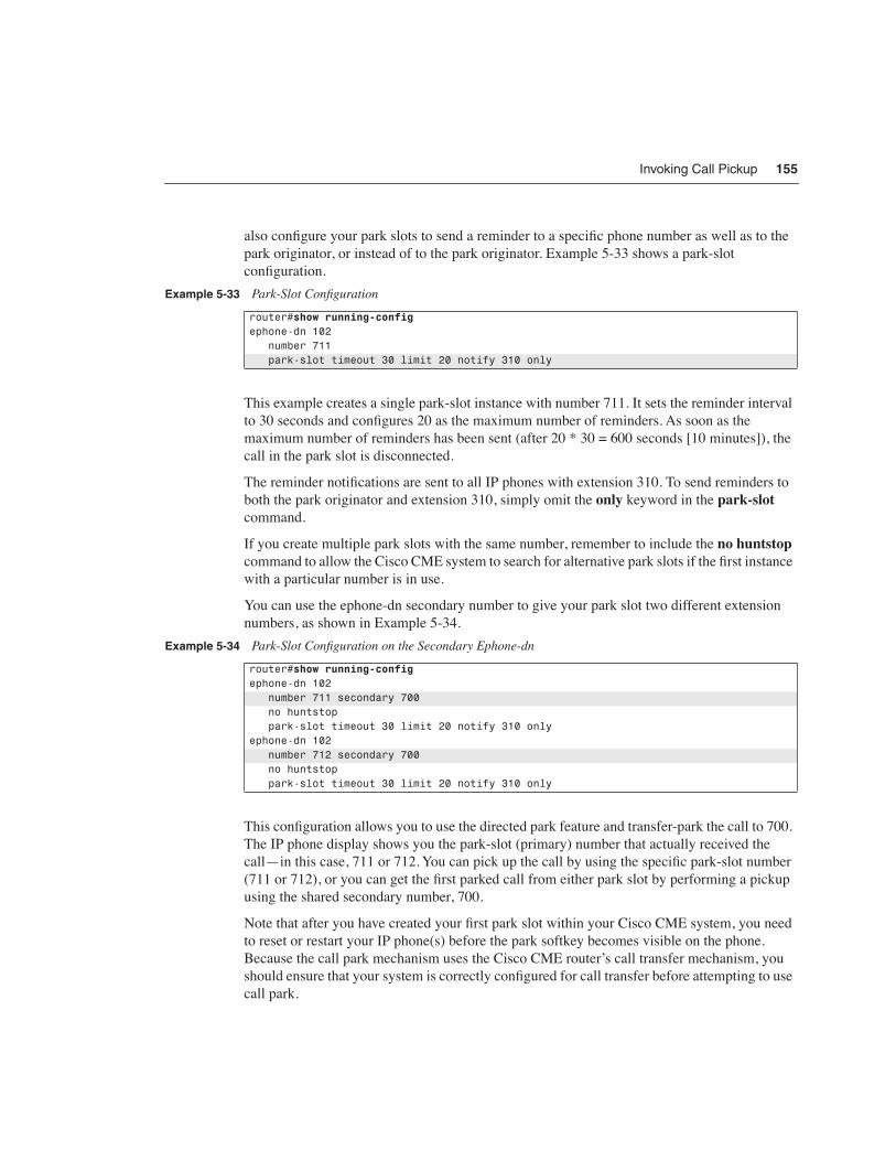
Invoking Call Pickup 155
also configure your park slots to send a reminder to a specific phone number as well as to the park originator, or instead of to the park originator. Example 5-33 shows a park-slot configuration.
This example creates a single park-slot instance with number 711. It sets the reminder interval to 30 seconds and configures 20 as the maximum number of reminders. As soon as the maximum number of reminders has been sent (after 20 * 30 = 600 seconds [10 minutes]), the call in the park slot is disconnected.
The reminder notifications are sent to all IP phones with extension 310. To send reminders to both the park originator and extension 310, simply omit the only keyword in the park-slot command.
If you create multiple park slots with the same number, remember to include the no huntstop command to allow the Cisco CME system to search for alternative park slots if the first instance with a particular number is in use.
You can use the ephone-dn secondary number to give your park slot two different extension numbers, as shown in Example 5-34.
This configuration allows you to use the directed park feature and transfer-park the call to 700. The IP phone display shows you the park-slot (primary) number that actually received the call—in this case, 711 or 712. You can pick up the call by using the specific park-slot number (711 or 712), or you can get the first parked call from either park slot by performing a pickup using the shared secondary number, 700.
Note that after you have created your first park slot within your Cisco CME system, you need to reset or restart your IP phone(s) before the park softkey becomes visible on the phone. Because the call park mechanism uses the Cisco CME router’s call transfer mechanism, you should ensure that your system is correctly configured for call transfer before attempting to use call park.
Example 5-33 Park-Slot Configuration
router#show running-configephone-dn 102 number 711 park-slot timeout 30 limit 20 notify 310 only
Example 5-34 Park-Slot Configuration on the Secondary Ephone-dn
router#show running-configephone-dn 102 number 711 secondary 700 no huntstop park-slot timeout 30 limit 20 notify 310 onlyephone-dn 102 number 712 secondary 700 no huntstop park-slot timeout 30 limit 20 notify 310 only

156 Chapter 5: Cisco CME Call Processing Features
Customizing SoftkeysCisco CME 3.2 and later allow you to customize the set of softkeys displayed to the phone user in each stage of a phone call. For example, by default in the connected call state, a Cisco 7960 IP Phone shows the following six softkeys:
• Acct (account code entry)
• Confrn (three-party conference)
• Endcall
• Flash (sends a hookflash signal to the PSTN line)
• Hold
• Trnsfer (call transfer)
Because a Cisco 7960 IP Phone has only four physical softkey buttons, the phone displays a more softkey as the rightmost button to allow the phone user to scroll to access all the keys. Because the more softkey itself uses one of the physical buttons, the user sees the feature softkeys in two sets:
• Hold
• Trnsfer
• EndCall
• More
• Confrn
• Acct
• Flash
• More
The softkey customization feature allows you to change this default behavior, and choose the set of keys you want to display. It also allows you to control the order of the keys so that you can move the more frequently used keys to the first page. For example, you may choose to remove the Acct and Flash keys from the connected state key set, leaving just the following four keys:
• Hold
• Trnsfer
• EndCall
• Confrn
Because this reduces the number of keys to just four, there is no need for a more softkey, allowing you to use all four physical phone buttons and present the softkeys as a single page.

Configuring Call Transfer and Forward 157
The ephone-template command is used to provide this configuration, as shown in Example 5-35. The order of the command options determines the order in which the softkeys appear on the phone.
Cisco CME 3.2 and later allow you to create up to five different ephone templates. Each template lists the softkeys available for each of the four configurable call states:
• Idle
• Seized
• Alerting
• Connected
The ringing call state for inbound calls cannot be configured because it offers only two softkeys: Answer and DND. As soon as you have created the ephone templates, you can apply them on a per-ephone basis. This allows you to optimize the soft key sets to support several different types of phone users. It also allows removal of softkeys in cases where you need to restrict access to certain functions for some phone users.
Table 5-1 shows the full set of customizations for all customizable call states.
The Seized call state is the initial dial tone state after going off-hook to place an outbound call. The Alerting state is the name of the call state after the telephone number has been dialed and the user is waiting for the called number to answer (or hears busy tone).
Configuring Call Transfer and ForwardConfiguring call transfer and forwarding for H.323 VoIP calls is a fairly complex task in most real-world H.323 VoIP networks. This is especially true if you have a mixture of H.323 VoIP
Example 5-35 ephone-template Command
router#show running-configephone-template 1 soft-key connected hold trnsfr endcall confrnephone 1 ephone-template 1
Table 5-1 Softkey Support Per Call State
Call State Available Softkeys
Idle Redial, CFwdAll, DND, PickUp, GPickUp, Newcall, Login
Seized Redial, CFwdAll, PickUp, GPickUp, EndCall
Alerting Acct, EndCall, CallBack
Connected Acct, Confrn, Hold, Trnsfr, Endcall, Flash, Park

158 Chapter 5: Cisco CME Call Processing Features
systems from different vendors. Even if you have an all-Cisco H.323 VoIP network, there are still interactions to consider, unless all your VoIP systems are running relatively up-to-date Cisco IOS software. This means having at least Cisco IOS 12.3 software in all your voice-enabled routers. Ideally, you should have Cisco IOS 12.3(4)T or later software (this is the Cisco CME 3.0 base code version). There are also some special considerations if you are using a Cisco CallManager in addition to your Cisco IOS-based Cisco CME systems, which you’ll learn more about in Chapter 7, “Connecting Multiple Cisco CMEs with VoIP.” The good news is that with the right software and configuration, there are workable solutions for most of your VoIP call transfer and forwarding needs.
In a VoIP network, getting an optimized system working for call transfer and forwarding requires the active cooperation of all endpoints involved in a call transfer or call forward. This means your ability to perform a call transfer or forward depends on the capabilities of the calling party’s VoIP system as well as your Cisco CME system configuration. A call transfer also depends on the capabilities of the final VoIP system that you are transferring the call to.
In traditional TDM-based PBX telephony, call transfer and forwarding usually operate within the limited scope of a single PBX system and, therefore, are simpler operations. For example, you are often limited to call transfers between extensions on the same PBX only.
In a VoIP-based system, you can potentially transfer or forward calls between any VoIP endpoints, regardless of their physical location. Of course, being able to do this in practice requires making sure that you have support for transfer and forwarding built into all your VoIP endpoints.
With Cisco CME, you have three basic choices for the protocol used to support call transfer and forwarding for H.323 VoIP calls:
• Standards-based H.450—Strongly recommended because it provides for optimal call paths and unlimited sequential transfers and forwards
• Cisco-proprietary H.323 extension—Mostly obsolete, but useful if you are using software older than Cisco IOS 12.2(15)T
• Hairpin call routing—Maximum compatibility but uses more WAN bandwidth and results in higher delay and jitter
The default H.323 call transfer protocol used by Cisco CME is the Cisco-proprietary mechanism. This mechanism supports only blind call transfer (that is, no transfer consultation). It is selected as the default simply for purposes of backward compatibility with earlier Cisco IOS versions.
The default call forwarding mechanism provides for automatic local forwarding only (that is, within the same Cisco CME system). It does not provide forwarding display update notification of the call forwarding to the calling party’s IP phone. For incoming VoIP calls from another Cisco CME system that are nonlocally forwarded to a third Cisco CME system, the Cisco-proprietary H.323 protocol extensions are used.

Configuring Call Transfer and Forward 159
Even if you do not require H.323 VoIP call transfers (because you do not need to make calls across an IP connection to another site), you should still select the H.450 configuration method for call transfers. This enables call transfer with consultation for local calls within your system and for PSTN calls that use PSTN voice ports that are physically on your Cisco CME router. (PSTN voice ports on a router other than the Cisco CME system appear as H.323 VoIP calls to the Cisco CME system.) It also prepares your system to use the standards-based H.450 protocol in case you want to add support for H.323 or SIP VoIP transfer and forwarding to another site at some point in the future.
Call Transfer TerminologyTo fully comprehend the different call flows when talking about transfers, you should be familiar with the following terms:
• Transferee—The person who is being transferred. Usually this is the person who placed the original call.
• Transferor—The person who invokes the transfer. Usually this is the initial recipient of the incoming call.
• Transfer-to—The person who becomes the final recipient of the call after the transfer has been completed.
• Consultation call—The call between the transferor and transfer-to parties. This is usually the call that introduces the transfer where the transferor and transfer-to parties talk (consult) before the transferee is connected to the transfer-to party.
• Transfer commit at connect—The act of completing the (consultative) transfer after the transferor and transfer-to party have talked to each other. The transferee party does not hear the transfer-to party’s phone ring. The transfer-to party’s phone shows the transferor as the (initial) calling party.
• Transfer commit at alerting—The act of committing the (consultative) transfer during the time that the transfer-to party’s phone is ringing. In this case, a consultation call is placed but is abandoned before the transfer-to party answers the phone. The transfer-to party’s phone shows the transferor as the (initial) calling party. The transferee party hears the transfer-to party’s phone ringing. Note that in a VoIP system, it’s usually not possible to commit a transfer to a busy destination, unless you use the blind transfer approach. You can commit a transfer to a busy destination that has call forward-on-busy, provided that the forward-to destination itself is available (for example, forward on busy to voice mail). However, none of this is necessarily visible to the transferor.
• Blind transfer—This is also called unsupervised transfer and sometimes full blind transfer. It is the act of invoking a call transfer without first checking to see if the transfer-to party is available. In the traditional TDM PBX world, this is often considered to be the same as commit at alerting when the transferor commits the transfer without waiting to hear the transfer-to party’s phone ring, usually by hanging up the phone. The transfer-to party’s phone shows the transferee as the calling party.
160 Chapter 5: Cisco CME Call Processing Features
In the VoIP world, there are two key differences between the blind and commit-at-alerting case. The first difference is in the calling party information sent in the H.323 call setup request toward the transfer-to party. In the blind case, this is the transferee, and in the commit at alerting/connect case, it’s the transferor. This can affect the billing for the call. The second difference is that a blind transfer doesn’t involve doing a call replace operation, which is needed to switch the transfer-to party’s call between transferor and transferee. So you might sometimes want to consider the blind form of transfer, because it eliminates the transfer capability dependency on the transfer-to endpoint VoIP system.
Call Transfer Methods for VoIPThis section describes several methods for implementing call transfer across VoIP networks:
• H.450 and SIP
• Hairpin routing
• H.450.12
• Empty Capability Set
H.450 and SIPThe ITU-T standards-based H.450.2 transfer method and the Cisco-proprietary method operate in a similar fashion. In both cases, when a call transfer occurs, a control message is sent back to the transferee party to request that the transferee initiates a follow-on call from the transferee to the final transfer-to destination. In the H.450.2 case, the follow-on call originated by the transferee can act to replace the transfer consultation call that’s in progress between the transferor and the transfer-to destination party. The consultation call between transferor and transfer-to and the original transferee-transferor call are not torn down until the “replaces” operation is completed successfully. The term replaces is used here in the context of “Call 2 replaces call 1.” If for any reason the replaces operation fails, it’s usually possible for the transferor to reconnect the call to the transferee. The H.450.2 mechanism works in a manner similar to the REFER method used for SIP VoIP calls. The Cisco-proprietary transfer mechanism does not support the call replacement mechanism and, therefore, allows you to perform only blind call transfers. This proprietary method is similar to the older BYE/ALSO method that was used to perform blind transfers for SIP VoIP calls. The BYE/ALSO method has been mostly superceded by the SIP REFER method.
Both of these H.323 call transfer methods result in an optimal direct call path between the transferee and the transfer-to party after the call transfer is committed.
Configuring Call Transfer and Forward 161
Hairpin RoutingThe third alternative is to hairpin route the VoIP call transfer. In this case, the original transferee-to-transferor VoIP call leg is kept, and a second transferor to transfer-to VoIP call leg is created for the consultation call phase of the transfer. When the transfer is committed, the original and consultation call legs are simply bridged together at the Cisco CME router. This method has the advantage that it has no end-to-end dependency on the capabilities of the transferee or transfer-to VoIP endpoint.
It also has disadvantages. One significant disadvantage is that the final transferred call is relayed through the transferor’s Cisco CME system. This means that the transferred call continues to consume resources on the transferor Cisco CME system even after the transfer is committed. It also means that the media path for voice packets for the transferred call may hairpin route through the transferor’s Cisco CME system, so both the original call and the transferred call continue to consume WAN bandwidth. If the amount of WAN bandwidth is limited, this may prevent new VoIP calls from being established until the transferred call is terminated. The other significant disadvantage of hairpin routing calls is the cumulative bandwidth, delay, and jitter problems that occur if a call is transferred multiple times (chained or sequential transfers).
H.450.12You can compromise between the H.450.2 and hairpin routing call methods by turning on the H.450.12 protocol on your Cisco CME system (this is recommended). You must be using at least Cisco CME 3.1 to use H.450.12. With H.450.12 enabled, your Cisco CME system can use the H.450.12 protocol to automatically discover the H.450.x capabilities of VoIP endpoints within your VoIP network. When H.450.12 is enabled, the Cisco CME system can automatically detect when an H.450.2 transfer is possible. When it isn’t possible, the Cisco CME system can fall back to using VoIP hairpin routing. Cisco CME also can automatically detect a call from a (non-H.450-capable) Cisco CallManager.
Empty Capabilities SetFor the sake of completeness, it’s worth mentioning a fourth alternative for call transfers: Empty Capabilities Set (ECS). Cisco CME does not support the instigation of transfer using ECS. But because a Cisco CME router also has the full capabilities of the Cisco IOS H.323 voice infrastructure software, it can process receipt of an ECS request coming from a far-end VoIP device. In other words, a Cisco CME system can be a transferee or transfer-to party in an ECS-based transfer. A Cisco CME system does not originate a transfer request using ECS. The problem with ECS-based transfers is that in many ways they represent a combination of the worst aspects of the end-to-end dependencies of H.450.2 together with the cumulative problems of hairpin for multiple transfers. Many ECS-based transfer implementations don’t allow you to transfer a call that has already been transferred in the general case of VoIP intersystem transfers.

162 Chapter 5: Cisco CME Call Processing Features
Cisco CME VoIP Call Transfer OptionsYour Cisco CME system by default is set up to allow local transfers between IP phones only. It uses the Cisco-proprietary H.323 call transfer extensions to transfer calls that include an H.323 VoIP participant.
To configure your Cisco CME system to use H.450.2 transfers (this is recommended), set transfer-system full-consult under the telephony-service command mode. You also have to use this configuration for SIP VoIP transfers.
To configure your Cisco CME system to permit transfers to nonlocal destinations (VoIP or PSTN), set the transfer-pattern command under telephony-service. The transfer-pattern command also allows you to specify that specific transfer-to destinations should receive only blind transfers. You also have to use this configuration for SIP VoIP transfers. The transfer-pattern command allows you to restrict trunk-to-trunk transfers to prevent incoming PSTN calls from being transferred back out to the PSTN (employee toll fraud). Trunk-to-trunk transfers are disabled by default, because the default is to allow only local extension-to-extension transfers.
To allow the H.450.12 service to automatically detect the H.450.2 capabilities of endpoints in your H.323 VoIP network, use the supplementary-services command in voice service voip command mode.
To enable hairpin routing of VoIP calls that can’t be transferred (or forwarded) using H.450, use the allow-connections command. Example 5-36 shows a call transfer configuration using this command.
The configuration shown in Example 5-36 turns on the H.450.2 (transfer-system full-consult) and H.450.12 services, allows VoIP-to-VoIP hairpin call routing (allow-connections) for calls that don’t support H.450, and permits transfers to all possible destinations (transfer-pattern). The transfer permission is set to .T to provide full wildcard matching for any number of digits. (The T stands for terminating the transfer destination digit entry with a timeout.)
Example 5-37 shows a configuration for more restrictive transfer permissions.
Example 5-36 Call Transfer Configuration
router#show running-configvoice service voip supplementary-service h450.12 allow-connections h323 to h323telephony-service transfer-system full-consult transfer-pattern .T
Example 5-37 More Restrictive Call Transfer Configuration
router#show running-configtelephony-service transfer-system full-consult transfer-pattern 1... transfer-pattern 2... blind

Configuring Call Transfer and Forward 163
This example permits transfers using full consultation to nonlocal extensions in the range 1000 to 1999. It also permits blind transfers to nonlocal extensions in the range 2000 to 2999.
Call Transfer Billing ConsiderationsYou should consider what your billing requirements are for transferred calls. Most enterprise VoIP networks have no requirement for separate billing for VoIP call legs within an internal VoIP network. Most enterprise networks are concerned only with billing for external PSTN call legs.
The billing for a PSTN call leg usually goes to the party identified as the calling party on the outbound PSTN call setup. For a PSTN call using ISDN BRI/PRI, the calling party number is passed from the Cisco CME extension that originated the call. You can use the Cisco CME dialplan-pattern or Cisco IOS voice dial peer translation rule commands to convert from two-to-five-digit abbreviated extension numbers into a national number format acceptable to your PSTN service provider. If you are using simple analog FXO port connections to connect to the PSTN (simple subscriber line), you have no control over the billing party information, so you can probably skip the rest of this section. Calls on an analog subscriber line are simply billed to the number associated with the subscriber line by the PSTN service provider.
For the ISDN PRI/BRI case, this is an area where the difference between transfer commit at connect/alerting and blind transfers may be significant. It’s also an area in which hairpin call routing may provide you with some advantages.
When an H.450.2-style transfer is committed at alerting/connected, the calling party number for the consultation call setup to the transfer-to party (from the transferor) is normally equal to the transferor’s phone number. This is usually the bill-to number that’s associated with the call. If the consultation call involves a PSTN call leg using PRI/BRI (either a direct PSTN connection on the Cisco CME router or a remote PSTN gateway call reached via an intermediate VoIP leg), it’s useful to have the initial calling party number for the outbound PRI/BRI PSTN leg equal to the transferor’s phone number. This assumes that you want any transferred call to be billed (or traceable) to the person who invokes the transfer. When the replaces operation is triggered to connect the transferee to the transfer-to party, the calling party information associated with the PSTN leg normally does not change. This means that even after the transferor has dropped out of the call, the call continues to be billed to the transferor, at least as far as the external PSTN call leg is concerned. This is true for PSTN access that’s directly on your Cisco CME router and also when the PSTN access is on a remote VoIP-PSTN gateway accessed via a VoIP link. This is because the H.450.2 call transfer replaces operation is confined to the H.323 VoIP network. The replaces operation normally cannot extend into the PSTN connection.
Transfers that use the blind mechanism work differently. In the blind transfer case, the transferor does not originate a consultation call. The initial call received by the transfer-to party in an H.450.2 transfer case by default has the transferee’s phone number as the calling party. The transferee is often a phone number belonging to some external party. You are often not permitted to bill calls to this phone number even if you want to. Your PRI/BRI PSTN connection

164 Chapter 5: Cisco CME Call Processing Features
is very likely to reject any outbound calls that attempt to claim an external number as the calling party identifier.
You can work around this issue in a couple of different ways, depending on the reason you chose to select the blind transfer method. For example, you may be using blind transfer to avoid the H.450.2 replaces operation if it is not supported by your PSTN access voice gateway. The workaround methods include the following:
• You can place a translation rule on the dial peer associated with the outgoing PRI/BRI PSTN port that overwrites the transferee calling party number with the general public phone number for your company.
• You can elect to force hairpin VoIP routing with transfer commit-at-alerting/connect as an alternative to blind transfer such that the outgoing PSTN call carries the transferor’s phone number.
To use the first alternative, you must have control of the PSTN gateway. This is true if the PSTN access is local to your Cisco CME router. This may not be true if you get remote PSTN access across a WAN connection from a VoIP telephony service provider (TSP). In this case, your VoIP TSP may share the PSTN access ports across multiple end customers.
The second hairpin case is the most robust approach, because it forces a separate call leg to be generated for the outgoing PSTN call segment.
To force hairpin VoIP call routing, you can switch on H.450.12 services on your Cisco CME router and use a separate PSTN gateway router on which H.450.12 is disabled (or not supported). Alternatively, you can explicitly turn off H.450.2 service on your Cisco CME voice dial peers that route calls to the PSTN gateway router. You do this using the no supplementary-service h450.2 command, as shown in Example 5-38.
Because Cisco CME includes the standard Cisco IOS voice infrastructure functionality, you can also connect your Cisco CME system to a Remote Authentication Dial-In User Service (RADIUS) server to capture call records for more detailed call tracking information collected. If you don’t have a RADIUS server, you can also configure your Cisco CME system to generate SYSLOG messages that include call details. You can use a simple PC as a SYSLOG server to record the call data, using one of several freeware SYSLOG programs available on the Internet.
Example 5-38 Turning Off H.450 on a Dial Peer
router#show running-configdial-peer voice 100 voip destination-pattern 9.T session target ipv4:10.0.1.20 no supplementary-service h450.2
Configuring Call Transfer and Forward 165
Call Forward Methods for VoIPThis section describes different mechanisms for handling call forwarding in a VoIP network:
• H.450.3 call forwarding
• H.323 Facility Message
• VoIP hairpin call forwarding
You can configure your Cisco CME to handle VoIP call forwarding in several different ways. Select the method to use depending on how you want forwarding to operate.
H.450.3 Call ForwardingYou can use the ITU-T H.450.3 standard for call forwarding (this is recommended). It has some similarities to H.450.2 (call transfer). When a call is forwarded, an H.450.3 message is sent back to the calling party requesting that the caller reoriginate a follow-on call to the forwarded-to destination. If Cisco CME is configured to use H.450.3, it is used even if the forward-to destination is another local IP phone within the same Cisco CME system as the forwarding phone (or forwarder). Use this method if you want the calling VoIP party to always be able to see the phone number he or she is being forwarded to. Just like the H.450.2 transfer case, use of H.450.3 requires that all the VoIP endpoints in your VoIP network support H.450 services.
H.323 Facility MessageThe second choice is to use the quasi-standard H.323 Facility Message mechanism for forwarding. This is the default call forwarding configuration for Cisco CME. This method is used as the default, because it provides backward compatibility with earlier (and current) Cisco IOS releases. It’s also quite widely supported by third-party and non-Cisco IOS VoIP systems. When this mechanism is used, an H.323 Facility Message is sent back to the VoIP caller only for the case of forwarding to a nonlocal number. If the forward-to destination is local to the forwarding phone, the call forward operation is handled internally within the Cisco CME system. In this case, the remote calling IP phone cannot update its display to show the forwarded destination.
VoIP Hairpin Call ForwardingYour third choice is to use VoIP call hairpin routing. This is similar to the call transfer hairpin option. A second independent VoIP call leg is created for the forwarded call leg. This leg is bridged to the original incoming VoIP call leg. As for the transfer hairpin case, the disadvantage of this approach occurs if you have to support sequential or chained forwarding. Sequential hairpin forwarding of VoIP calls results in accumulated bandwidth and jitter/delay issues.
Just like the call transfer discussion, if you have to deal with only local LAN and PSTN connections and do not have to route VoIP H.323 calls across a WAN connection, you can just

166 Chapter 5: Cisco CME Call Processing Features
configure your system for H.450.3 operation to get your system ready to interoperate with other H.450-capable endpoints should you need this in the future.
You can also compromise between the H.450.3 and hairpin configuration by using the H.450.12 service to automatically detect H.450.3-capable VoIP endpoints, and fall back to hairpin routing for calls that don’t support H.450.3.
Cisco CME VoIP Call Forwarding OptionsYour Cisco CME system by default is configured to support internal local forwarding. It sends only H.323 Facility Messages back to the VoIP caller for nonlocal VoIP forwarding destinations. If you have direct PSTN access on your Cisco CME system, PSTN destinations accessed via local ports are considered local for the purposes of this discussion.
To turn on H.450.3 services for VoIP calls, you use the call-forward pattern command under telephony-service. This command lets you conditionally select H.450.3 service based on matching the calling party’s telephone number. This lets you invoke H.450.3 for calls only from VoIP phone numbers that you know support H.450.3. You can configure the matching pattern to use .T to match all possible calling party numbers. This is similar to the match-all configuration used with the transfer-pattern command.
To permit VoIP-to-VoIP hairpin (or tandem) call routing for forwarded calls, set the allow-connections command under voice services voip. If you’ve already done this to allow hairpin transfers, you don’t need to do it again for call forwarding.
As with the H.450.2 transfer case, you can turn on the H.450.12 service to compromise and allow H.450.3 where possible, and fall back to hairpin forwarding otherwise. Note that H.450.12 support was introduced in Cisco CME 3.1.
Example 5-39 shows a basic configuration.
Call Forward Billing ConsiderationsSimilar billing issues apply to call forwarding as for call transfer. You can choose to have the calling party information for the forwarded call reflect the party being forwarded (in the H.450.3 case). You also can have the information show the calling party number of the phone that requested the forwarding (in the VoIP hairpin case). As for the call transfer case, you can use the dialplan-pattern command and voice dial peer translation rule options to control the format of the calling party on outgoing PSTN PRI/BRI calls. Again, this issue does not apply for PSTN analog subscriber line connections via FXO ports.
Example 5-39 Turning On H.450 on a Dial Peer
router#show running-configvoice service voip supplementary-service h450.12 allow-connections h323 to h323telephony-service call-forward pattern .T
Configuring Call Transfer and Forward 167
Transfer and Forward Proxy FunctionThe transfer and forward discussion so far in this chapter has related to the configuration of a single Cisco CME system to cope with various possible VoIP network scenarios, including networks that have endpoints with mixed capabilities. If you have a network of Cisco CME systems, you should consider partitioning it to provide a section that contains only H.450-capable endpoints. This allows you to gain the full set of H.450 service benefits within the group of VoIP network devices that support them. You can then link this segment of your VoIP network to the non-H.450 network using a Cisco IOS router configured to act as an H.450 Tandem Gateway.
An H.450 Tandem Gateway can act as a proxy for H.450.2 and H.450.3 services on behalf of VoIP devices that don’t support H.450. Calls between the H.450 and non-H.450 devices can be routed to pass through the H.450 Tandem Gateway. H.450 messages originated by Cisco CME systems can be terminated on the H.450 Tandem Gateway, which can invoke hairpin call routing for transfers and call forwarding as needed.
An H.450 Tandem Gateway makes the most sense if your network topology is arranged in a hub-and-spoke fashion. Consider a network design that has a number of Cisco CME systems located at the end of WAN link spokes connected to a central hub network. In this type of network, it often makes sense to locate an H.450 Tandem Gateway at the central hub and to use it as a linkage point to act as a bridge into the non-H.450 segment of the VoIP network. With an H.450 Tandem Gateway, calls that enter the H.450 network segment through the Tandem Gateway can be transferred and forwarded using H.450 services within the H.450 segment of the network. Calls transferred or forwarded to destinations outside the H.450 segment are hairpin routed as needed by the H.450 Tandem Gateway. If the H.450 Tandem Gateway is located at a central hub location, hairpin routing the call at the hub is a better option than hairpin routing the call from a Cisco CME system located at the far end of one of the network spokes over a WAN link. (Figure 5-3 in the next section shows a Tandem Gateway.)
Call Transfer and Forward Interoperability with Cisco CallManagerCisco CallManager (version 4.0 and earlier) does not support H.450 services. Cisco CME 3.1 can automatically detect H.323 calls that go to or come from Cisco CallManager. It does this using H.323 information elements included in H.323 call setup, progress, alerting, and connect messages. You can optionally turn on H.450.12 services for calls to Cisco CallManager, and use the lack of H.450.12 indications to invoke hairpin VoIP call routing by your Cisco CME systems, but this is not required.
You may have a VoIP network in which turning on H.450.12 produces ambiguous results as far as the detection of H.450.2 and H.450.3 capabilities. One example of this occurs when you have older Cisco CME 3.0 (or even Cisco ITS [Cisco CME’s earlier name] 2.1) systems in your network. Although Cisco CME 3.0 systems do support H.450.2 and H.450.3, they don’t support H.450.12 capabilities indications. If you turn on H.450.12 on your Cisco CME 3.1 systems and you also have some older Cisco CME 3.0 routers, the CME 3.1 systems assume that the CME
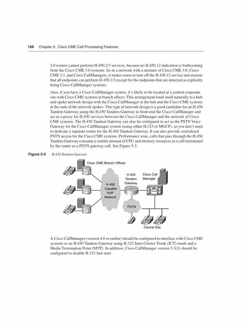
168 Chapter 5: Cisco CME Call Processing Features
3.0 routers cannot perform H.450.2/3 services, because no H.450.12 indication is forthcoming from the Cisco CME 3.0 systems. So in a network with a mixture of Cisco CME 3.0, Cisco CME 3.1, and Cisco CallManagers, it makes sense to turn off the H.450.12 service and assume that all endpoints can perform H.450.2/3 except for the endpoints that are detected as explicitly being Cisco CallManager systems.
Also, if you have a Cisco CallManager system, it’s likely to be located at a central corporate site with Cisco CME systems at branch offices. This arrangement lends itself naturally to a hub-and-spoke network design with the Cisco CallManager at the hub and the Cisco CME systems at the ends of the network spokes. This type of network design is a good candidate for an H.450 Tandem Gateway using the H.450 Tandem Gateway to front-end the Cisco CallManager and act as a proxy for H.450 services between the Cisco CallManager and the network of Cisco CME systems. The H.450 Tandem Gateway can also be configured to act as the PSTN Voice Gateway for the Cisco CallManager system (using either H.323 or MGCP), so you don’t need to dedicate a separate router for the H.450 Tandem Gateway. It can also provide centralized PSTN access for the Cisco CME systems. Performance wise, calls that pass through the H.450 Tandem Gateway consume a similar amount of CPU and memory resources as a call terminated by the router as a PSTN gateway call. See Figure 5-3.
Figure 5-3 H.450 Tandem Gateway
A Cisco CallManager (version 4.0 or earlier) should be configured to interface with Cisco CME systems or an H.450 Tandem Gateway using H.323 Inter-Cluster Trunk (ICT) mode and a Media Termination Point (MTP). In addition, Cisco CallManager version 3.3(3) should be configured to disable H.323 fast-start.
�����
�������
����
������
��!�
�"�� �$% &��'�( )**"��
��'���� �"��
�����
!�'+�,
-�����.
�"�� ����
$�'�/��
��
��
��
�� ��
�

Summary 169
Call Transfer and Forwarding with Routed Signaling H.323 GatekeepersAn H.323 gatekeeper that uses routed signaling acts as a call proxy for basic A-to-B calls. All calls that reference the gatekeeper have H.323 signaling that passes through the gatekeeper. The presence of this type of gatekeeper in your network has a significant impact on your network from the H.450 service point of view. Your routed signaling gatekeeper may or may not support H.450 services. It may be able to pass through H.450 messages transparently, or it may block some or all of them. It may even be able to act as an H.450 Tandem Gateway.
A worst-case design approach for dealing with a routed signaling gatekeeper would be to assume that H.450.2/3 services do not work through the gatekeeper. In this case you can configure your Cisco CME systems to force hairpin routing of all VoIP calls that have to transfer or forward back into the VoIP network. You can do this by turning off H.450 services under the voice service voip command, as shown in Example 5-40.
Note that by default, the H.450.12 service is disabled, so there’s no need to specifically include commands to turn it off.
SummaryIn this chapter, you read about some of the more popular Cisco CME phone and call processing features. You saw examples of how these features can be configured and combined to provide a rich and flexible set of functions. You also saw how to configure call transfer and forwarding functions in a variety of network scenarios.
Example 5-40 Turning Off H.450 Services
router#show running-configvoice service voip no supplementary-service h450.2 no supplementary-service h450.3 allow-connections h323 to h323telephony-service call-forward pattern .T transfer-system full-consult transfer-pattern .T
Related Documents