Concrete Structural Design for Sustainability in Residential and Small Commercial Buildings “How can ‘structural form’ contribute to better solutions?” Department of Civil Engineering Prepared for: Prof Mark Alexander Mr Vernon Collis Prepared by: Koketšo Moyaba (MYBKOK001) Course: CIV4044S Submission Date: 11 November 2013

Welcome message from author
This document is posted to help you gain knowledge. Please leave a comment to let me know what you think about it! Share it to your friends and learn new things together.
Transcript
Concrete Structural Design for Sustainability in
Residential and Small Commercial Buildings
“How can ‘structural form’ contribute to better solutions?”
Department of Civil Engineering
Prepared for:
Prof Mark Alexander
Mr Vernon Collis
Prepared by:
Koketšo Moyaba (MYBKOK001)
Course:
CIV4044S
Submission Date:
11 November 2013
i
Plagiarism Declaration
I know that plagiarism is wrong. Plagiarism is to use another’s work and to pretend that it
is one’s own.
I have used the Harvard convention for citation and referencing. Each contribution to,
and quotation in, this thesis from the work or works of other people has been attributed,
and has been cited and referenced.
This thesis is my own work.
I have not allowed, and will not allow, anyone to copy my work with the intension of
passing it off as his or her own work.
Student Number Name Signature
MYBKOK001 Moyaba, Koketšo
ii
Abstract
Concrete structures have been designed throughout history by paying attention to their form.
Before the invention of reinforced concrete, it was imperative to design a concrete structure that
took mainly if not entirely compressive loads. This was done to avoid the relative weakness of
earlier building materials, including unreinforced concrete under tensile loads. These form-active
concrete structures are potentially the most efficient concrete structural components with regard
to their load carrying capacity in relation to their weight. Form-active design is more complex
since it requires an understanding of the shape the concrete structure would take under a
particular load if it had no bending stiffness, i.e. if it were to behave like a cable. Due to the high
structural efficiency, form-active structures play an important role with regard to sustainability.
They use less material to achieve higher load carrying capacities, and therefore they reduce the
use of natural resources.
This thesis focuses on concrete floor slabs in residential buildings and small commercial
buildings. The aim is to study the behaviour of these slabs under loading and analyse how
structural form considerations can lead to better design solutions. These structural components
were chosen due to their significant contribution to the construction of both residential and small
commercial buildings. However, this choice imposes certain restrictions in the freedom of
designing form-active structures; i.e. dimensional restriction such as depth of the slab, flatness of
the slab on the top surface, etc. These restrictions are important since they determine whether the
slab will be able to correctly perform its function.
The analytical methodology involved designing a set of traditional solid slabs and improving
their designs according to material and cost optimisations. These slabs were then compared with
form active slabs which were designed to take the parabolic shape of their bending moment
diagrams. From an analysis of the designs, it was found that form active slabs are approximately
two times more efficient than the traditional solid slab. This efficiency is with regard to load
carrying capacity and the amount of material used, both concrete and steel. The reduction in the
concrete used for a form-active slab with the same span as a traditional solid slab, can be
approximately 60% and that of steel can be approximately 70%. These values are a clear
indication that the consideration of structural form can lead to better and sustainable solutions.
One way spanning slabs can be applied to both residential and small commercial buildings since
these buildings are commonly constructed as post-and-beam structures, with discontinuous
joints. Furthermore these buildings have significantly lower and more predictable loads than
other types of buildings. This helps with regard to avoiding failure by unexpected excessive
point loads. Larger commercial and institutional buildings such as malls, hospitals, etc. can also
adopt the application of one way spanning form-active slabs. This is because of the common
attribute most of these buildings have, which is large hallways and corridors, which are suitable
application areas for these types of slabs. This thesis has in this regard successfully shown the
economical and sustainable advantages of concrete structural design through the consideration of
structural form by investigating the special case of one way form-active slabs.
iii
Acknowledgements
I would like to extend my gratitude to the following people who were helpful in the compiling of
this thesis:
Prof Mark Alexander:
For the excellent supervision throughout the entire project, and equally important I appreciate
the guidance which kept me on track in all respects of the research; this includes problem
solving methodologies, thorough checking on progress and the writing of this document, and
useful insight on concrete properties related to the problem statement posed by this thesis, thank
you.
Mr Vernon Collis, PrEng:
Thanks are due for providing insight on the topic of form-active structures and pointing to the
excellent resources from which the bulk of this thesis is based. Moreover, I appreciate the
guidance with regard to the practical design of form-active slabs, including that of structures that
comes with both experience and passion, ke a leboga.
iv
Table of Contents
Plagiarism Declaration i
Abstract ii
Acknowledgements iii
Table of Contents iv
List of Figures vii
List of Tables viii
List of Equations viii
Glossary of terms and abbreviations ix
1 Introduction 1
1.1 Background 1
1.2 Problem Statement 2
1.3 Scope of Thesis 2
2 Motivation for Study 4
2.1 Introduction 4
2.2 Advances in Concrete Slab Design in the Last Century 4
2.2.1 Hollow Core Slabs 4
2.2.2 Bubble Deck Slabs 4
2.2.3 Holedeck Slabs 5
2.3 Project Proposal 8
2.3.1 Objectives of Thesis 8
2.3.2 Expected Outcome of Research 8
2.3.3 Strategy 8
2.3.4 Computer Aided Modelling 9
2.4 Closure 9
3 Literature Review – General Overview 10
3.1 Introduction 10
3.2 Properties of Concrete 10
3.3 Concrete Structures throughout History 11
3.4 Traditional Concrete Slab Design Process 14
3.4.1 Ultimate Limit State Design 14
3.4.2 Serviceability Design 15
v
3.5 Concrete Slab Design for Suspended Slabs 16
3.5.1 Inherent Inefficiencies in Solid Slab Design 17
3.5.2 Advantages of Solid Slab Design 18
3.6 Concrete Slab Design for ‘Slab-on-Grade’ 19
3.7 Sustainable Design 20
3.8 Closure - Main Findings from Literature 21
4 Design of Form-Active Structures 22
4.1 Introduction 22
4.2 Rigidity of the Element 22
4.3 Influence of Form-Active Shape 23
4.4 Influence of Load Pattern 24
4.4.1 Point Loads 24
4.4.2 Uniformly distributed Loads 24
4.5 Degree of Form-Active Elements 25
4.6 Structural Efficiency 27
4.7 Restrictions in Designing Form-active Slabs 27
4.7.1 Comparison of Continuous and Discontinuous Structures 27
4.8 Closure 29
5 Analytical Methodology 30
5.1 Introduction 30
5.2 Choice of Load Analysis Method 30
5.3 Traditional Solid Slab Design 31
5.3.1 Optimisation of the Solid Slab Design 32
5.3.2 Structural Efficiencies 34
5.4 Form-Active Slab Design 34
5.4.1 Roof Slab Design 35
5.4.2 Floor Slab Design 37
5.4.3 Comparison of Form-active Shapes 37
5.4.4 Structural Efficiencies 38
5.5 Closure 38
6 Discussion of Results 39
6.1 Introduction 39
vi
6.2 Comparison of Structural Efficiencies 39
6.3 The Effect of Increasing the Concrete Crushing Strength fcu 41
6.4 Comparisons from FEA Models 42
6.4.1 Setting up of Abaqus Models 42
6.4.2 Discussion of FEA Results 44
6.4.3 Failure Modes of Form-active Slabs 48
6.5 Closure 49
7 Conclusions 50
7.1 Specific Conclusions 50
7.2 General Conclusions 52
8 References 53
Appendices 55
Appendix A - Solid Slab Design Calculations 56
Appendix B - Load Analysis 61
Appendix C - Optimisation of Solid Slabs, Slab A and Slab D 65
Appendix D - Form-Active Slab Design 68
Appendix E - Drawings 72
vii
List of Figures
Figure 1: Bubble deck slab (Source: Structural Engineers, Sustainability and Leed®) ............................................... 5
Figure 2: Holedeck system at Logytel R+D building (Source: Holedeck the lean structure, online) ........................... 6
Figure 3: Rib form holedeck (Holedeck, the lean structure) ......................................................................................... 6
Figure 4: Structural efficiency chart, Macdonald ......................................................................................................... 7
Figure 5: Inside the Pantheon, Italy, Rome, (Source: Giovanni Paolo Pannini, Left), Cross-section and Plan of the
Pantheon (Right) ......................................................................................................................................................... 12
Figure 6:1935 Zarzuela Hippodrome by Eduardo Torroja (Source: International Database and Gallery of Structures,
Online) ........................................................................................................................................................................ 13
Figure 8: Actual and equivalent stress distribution at failure. (Source: SABS 0100-1: 4.3.3.3) ................................ 15
Figure 7: Cracked RC beam section, showing qualitatively the amount of concrete being ignored. .......................... 17
Figure 9: Tensile form-active shapes, (Top) and equivalent compressive form-active shapes, (Bottom) (Source
MacDonald) ................................................................................................................................................................ 24
Figure 10: Bending moment parabola plotted with arc passing through the same points ........................................... 27
Figure 11: Material optimisation graph of steel vs. concrete, Moyaba ....................................................................... 33
Figure 12: Cost optimisation graph, Moyaba ............................................................................................................. 34
Figure 13: Form-active slab stress distribution, Moyaba ............................................................................................ 36
Figure 14: Form-active floor slab ............................................................................................................................... 37
Figure 15: Example of form-active slab showing cross sectional areas for efficiency calculations, Moyaba ............ 38
Figure 16: Comparison of required concrete in Solid and Form-active slabs for different spans, Moyaba ................ 40
Figure 17: Comparison of required steel in Solid and Form-active slabs for different spans, Moyaba ...................... 41
Figure 18: Dimensions used for modelling the 1m strip form-active slab, Moyaba ................................................... 42
Figure 19: Solid Slab A model showing loading and end supports (left); Form-active Slab A showing loading and
end supports (right), Moyaba ...................................................................................................................................... 43
Figure 20: Von Misses contour plot for the 6m span solid slab fixed at both ends, Moyaba ..................................... 45
Figure 21: Element group of the mid-span of the solid slab in figure 20, Moyaba .................................................... 45
Figure 22: Isometric top view of form-active slab showing the von Mises contour plot, Moyaba ............................. 46
Figure 23: Top view of form-active slab showing the von Mises contour plot, Moyaba ........................................... 46
Figure 24: Isometric bottom view of the form-active slab showing the von Mises contour plot, Moyaba ................. 47
Figure 25: Cross section of the mid-span of the form-active slab showing the von Mises stresses, Moyaba ............. 47
Figure 26: Detail showing correct support connection and lateral support connection in form-active slabs, Collis .. 49
viii
List of Tables
Table 1: Comparison of Bending Moment Parabola and Arc of a Circle ................................................................... 26
Table 2: Comparison of Continuous and Discontinuous Structures, Moyaba, ref. MacDonald ................................. 28
Table 3: Typical span/depth ratios, (Cobb, 2004) ....................................................................................................... 31
Table 4: Summary of solid slab design (Appendix A), Moyaba................................................................................. 39
Table 5: Summary of form-active roof slab design (Appendix E), Moyaba ............................................................... 39
Table 6: Material reduction obtained by designing form-active slabs, Moyaba ......................................................... 40
List of Equations
Equation 1: Ultimate load equation, SANS 0100-1 .................................................................................................... 14
Equation 2: General equation of a parabola ................................................................................................................ 26
Equation 3: Implicit equation of a circle with its centre on the y-axis........................................................................ 26
Equation 4: Explicit equation of circle with respect to y ............................................................................................ 26
Equation 5: Structural Efficiency ............................................................................................................................... 27
Equation 6: Ratio of maximum Y value to minimum Y value for axes alignment ..................................................... 33
Equation 7: Fundamental defining equation of a moment force ................................................................................. 36
Equation 8: SI Equation of concrete's elasticity modulus based on empirical values, PCI ........................................ 43
Equation 9: von Mises stress equation ........................................................................................................................ 44
ix
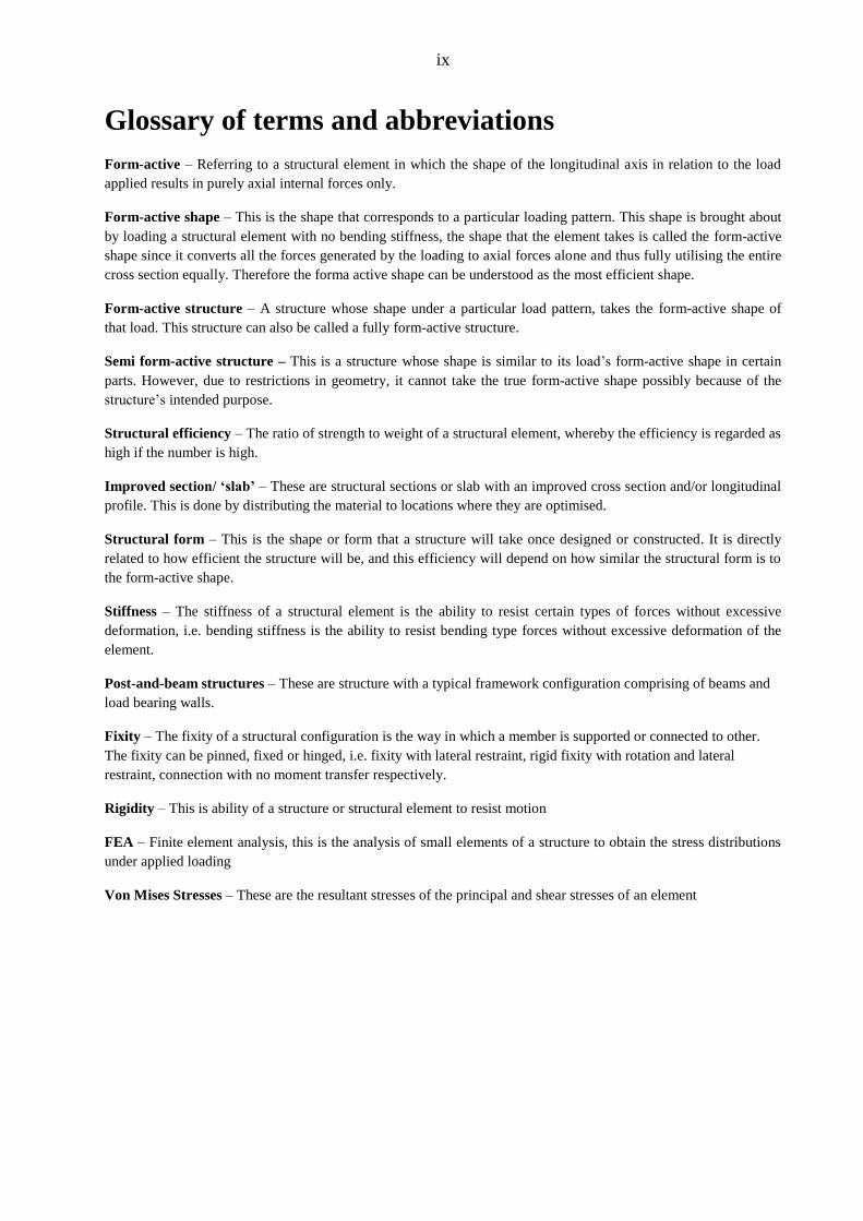
Glossary of terms and abbreviations
Form-active – Referring to a structural element in which the shape of the longitudinal axis in relation to the load
applied results in purely axial internal forces only.
Form-active shape – This is the shape that corresponds to a particular loading pattern. This shape is brought about
by loading a structural element with no bending stiffness, the shape that the element takes is called the form-active
shape since it converts all the forces generated by the loading to axial forces alone and thus fully utilising the entire
cross section equally. Therefore the forma active shape can be understood as the most efficient shape.
Form-active structure – A structure whose shape under a particular load pattern, takes the form-active shape of
that load. This structure can also be called a fully form-active structure.
Semi form-active structure – This is a structure whose shape is similar to its load’s form-active shape in certain
parts. However, due to restrictions in geometry, it cannot take the true form-active shape possibly because of the
structure’s intended purpose.
Structural efficiency – The ratio of strength to weight of a structural element, whereby the efficiency is regarded as
high if the number is high.
Improved section/ ‘slab’ – These are structural sections or slab with an improved cross section and/or longitudinal
profile. This is done by distributing the material to locations where they are optimised.
Structural form – This is the shape or form that a structure will take once designed or constructed. It is directly
related to how efficient the structure will be, and this efficiency will depend on how similar the structural form is to
the form-active shape.
Stiffness – The stiffness of a structural element is the ability to resist certain types of forces without excessive
deformation, i.e. bending stiffness is the ability to resist bending type forces without excessive deformation of the
element.
Post-and-beam structures – These are structure with a typical framework configuration comprising of beams and
load bearing walls.
Fixity – The fixity of a structural configuration is the way in which a member is supported or connected to other.
The fixity can be pinned, fixed or hinged, i.e. fixity with lateral restraint, rigid fixity with rotation and lateral
restraint, connection with no moment transfer respectively.
Rigidity – This is ability of a structure or structural element to resist motion
FEA – Finite element analysis, this is the analysis of small elements of a structure to obtain the stress distributions
under applied loading
Von Mises Stresses – These are the resultant stresses of the principal and shear stresses of an element
1
Moyaba: Concrete design for sustainability (Structural form)
Introduction
1 Introduction
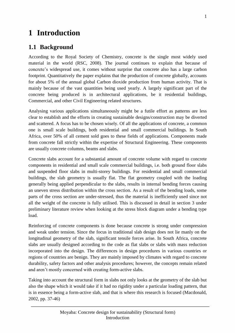
1.1 Background
According to the Royal Society of Chemistry, concrete is the single most widely used
material in the world (RSC, 2008). The journal continues to explain that because of
concrete’s widespread use, it comes without surprise that concrete also has a large carbon
footprint. Quantitatively the paper explains that the production of concrete globally, accounts
for about 5% of the annual global Carbon dioxide production from human activity. That is
mainly because of the vast quantities being used yearly. A largely significant part of the
concrete being produced is in architectural applications, be it residential buildings,
Commercial, and other Civil Engineering related structures.
Analysing various applications simultaneously might be a futile effort as patterns are less
clear to establish and the efforts in creating sustainable designs/construction may be diverted
and scattered. A focus has to be chosen wisely. Of all the applications of concrete, a common
one is small scale buildings, both residential and small commercial buildings. In South
Africa, over 50% of all cement sold goes to these fields of applications. Components made
from concrete fall strictly within the expertise of Structural Engineering. These components
are usually concrete columns, beams and slabs.
Concrete slabs account for a substantial amount of concrete volume with regard to concrete
components in residential and small scale commercial buildings, i.e. both ground floor slabs
and suspended floor slabs in multi-storey buildings. For residential and small commercial
buildings, the slab geometry is usually flat. The flat geometry coupled with the loading
generally being applied perpendicular to the slabs, results in internal bending forces causing
an uneven stress distribution within the cross section. As a result of the bending loads, some
parts of the cross section are under-stressed, thus the material is inefficiently used since not
all the weight of the concrete is fully utilised. This is discussed in detail in section 3 under
preliminary literature review when looking at the stress block diagram under a bending type
load.
Reinforcing of concrete components is done because concrete is strong under compression
and weak under tension. Since the focus in traditional slab design does not lie manly on the
longitudinal geometry of the slab, significant tensile forces arise. In South Africa, concrete
slabs are usually designed according to the code as flat slabs or slabs with mass reduction
incorporated into the design. The differences in design procedures in various countries or
regions of countries are benign. They are mainly imposed by climates with regard to concrete
durability, safety factors and other analysis procedures; however, the concepts remain related
and aren’t mostly concerned with creating form-active slabs.
Taking into account the structural form in slabs not only looks at the geometry of the slab but
also the shape which it would take if it had no rigidity under a particular loading pattern, that
is in essence being a form-active slab, and that is where this research is focused (Macdonald,
2002, pp. 37-46)
2
Moyaba: Concrete design for sustainability (Structural form)
Introduction
1.2 Problem Statement
The problem concrete slab design in residential and small commercial buildings faces is the
standardised design procedure since it does not take account of the form-active shape a slab
would take under its service or ultimate loading scenario. It is noteworthy to appreciate the
constraints posed on slabs in residential and small commercial buildings with regard to the
form/shape they may take. However, given today’s regressing state of the environment, the
design needs to incorporate sustainability. To do so, materials being used should be designed
to act in their strongest nature for efficiency, and for concrete that strength is in compression,
hence the focus of this thesis being on structural from in slabs.
The focus is to investigate how the structural form of ground floor and suspended slabs could
be altered to help them experience almost entirely compressive forces as opposed to tensile
forces, thus allowing for reduction of the concrete strengths. The investigation will be
reserved for suspended floor slabs because of the relative urgency with regard to higher
bending stresses. Slabs-on-grade are continuously supported on the ground they are cast on
and thus minimal bending stresses occur thus they are thinner than suspended floors and
generally require less reinforcing, mostly just for crack control.
Before looking at structural form in suspended floor slabs for residential and small
commercial buildings, other tools for improving structural efficiency need to be looked at so
as to be able to reasonably compare efficiencies, these are covered in the preliminary
literature review. The methods researched are all mass reduction methods or improved
sections; they are concerned with either improving the profile section of a slab or the cross
section of the slab. These methods are commonly used and they have the structural advantage
of maintaining an overall shape similar to that of a flat slab which allows it to carry out its
duty.
With regard to structural form in suspended floor slabs, there are some restrictions, the
obvious ones being the shape itself. Since the main purpose of the slab is to carry furniture,
people, etc. it is generally required to be flat on top, and again a height restriction is also
obvious with regard to depth. Compressive form-active structures also pose a unique
challenge. These structures are rigid and thus with changing load patterns or magnitude they
cannot adapt the new required form-active shape of the new load and thus bending stresses
will develop in the slabs. These challenges are to be addressed in this thesis.
1.3 Scope of Thesis
Given the broad applications of concrete as a building material, this thesis will not look at all
applications of concrete. The chosen focus area will be residential and small commercial
buildings’ ground and suspended floor slabs, particularly suspended floor slabs. This is
because within the mentioned buildings themselves, floor slabs account for a significant
amount of concrete used. Moreover, residential and small commercial buildings are a
significant contributor to all construction works, locally and also globally. Therefore it is a
fruitful basis for investigation to consider the issues of sustainable designs with regard to the
abovementioned alone and disregarding the design of other concrete structural components.
3
Moyaba: Concrete design for sustainability (Structural form)
Introduction
Sustainability is often a vague term, with different meanings attached to it, even within the
Built Environment itself. For the purposes of this thesis, the following definition will be used:
“Meet[ing] the needs of the present generation without compromising the ability of the future
generations to meet their needs” (Brundtland & World Commision on Enviroment and
Development, 1987). The level at which the use of concrete is used ought to be one that sees
concretes carbon footprint being reduced and so is the extraction of the raw materials for
production of concrete.
This thesis will base its study on existing methods of the design of concrete structures. It will
take a purely theoretical approach on the investigation since the methods being investigated
already have an extensive backing of empirical data. The thesis aims at finding out how the
current methods of design in the concrete slabs mentioned earlier could be augmented by
other innovative methods observed throughout history, i.e. Structural form.
An outline of the scope of this thesis is as follows:
Conducting an overview study of form-active structures throughout recorded
History, mostly in architecture
A study of different types of floor slabs used in practise, particularly ‘improved’ slabs
with a higher structural efficiency and placing them on a scale in comparison to the
traditional solid slab and from active structures
(Preliminary Literature Review)
A comprehensive desk study of form-active structures, with particular reference to
suspended floor slabs in residential and small commercial buildings. The study is to
look at the limitations of imposing structural form on these types of concrete floor
slabs
An overview study of the relationship of form-active structures and the bending
moment diagram. This will extend to a vital analysis of the similarities of the bending
moment diagram to the shape of a parabola and catenary and which of the two shapes
is suitable to adopt to represent a form-active shape and when it is suitable
(Continued Literature Review)
Finally, a set of solid slabs (representative to typical dimensions residential
buildings’ floor slabs or small commercial buildings will have) are to be designed.
The load carrying capacities of each of these slabs are to be calculated and their
structural efficiencies determined by taking the ratio of their calculated strengths to
their particular weights. From these efficiencies, an attempt at obtaining a pattern will
be made. From the findings of the research on form-active structures, catenary curves,
parabolas and bending moment diagrams, an attempt in imposing some of these
shapes on the abovementioned slabs. The shapes are to be added to the solid slabs as
negative volumes to reduce the overall mass of the slabs in order to minimise the
internal bending stresses within the slabs. All the slabs are to be designed as one way
spanning to better understand their behaviour from first principles. Using finite
element analysis, a comparison and discussion of the results from the designs is to be
carried out from where conclusions will be drawn.
4
Moyaba: Concrete design for sustainability (Structural form)
Motivation for Study
2 Motivation for Study
2.1 Introduction
As mentioned under the introduction in the previous section, concrete is the world’s most
widely used building material (RSC, 2008). The work that goes into constructing residential
and small commercial buildings is immense, and so is the concrete utilised. In the last half
century, residential and small commercial buildings have been designed and constructed
using some inefficient components with regard to their structural form, in particular ground
and suspended floor slabs.
The following sub-sections show previous innovations in concrete floor slab design, these
innovations were established in the previous century and they serve as an example of the
success of designing more efficient concrete slabs. These examples will serve as motivation
for research in improving concrete slabs by changing their structural form. Thereafter the
project proposal will be outlined.
2.2 Advances in Concrete Slab Design in the Last Century
2.2.1 Hollow Core Slabs
Simply put, these slabs have one directional hollows. Structurally they can be idealised as a
series of I-beams or T-beams. “In the mid-20th
century, the voided or hollow core floor
system was created to reduce the high weight-to-strength ratio of typical concrete systems.
This concept removes and/or replaces concrete from the center of the slab, where it is less
useful, with a lighter material in order to decrease the dead weight of the concrete floor.
However, these hollow cavities significantly decrease the slabs resistance to shear and fire,
thus reducing its structural integrity” (Lai, 2010, p. 7; Anastas & Zimmerman, 2003)
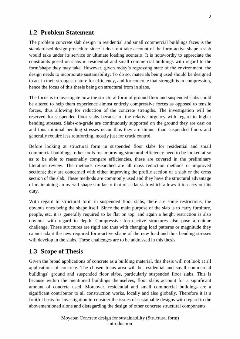
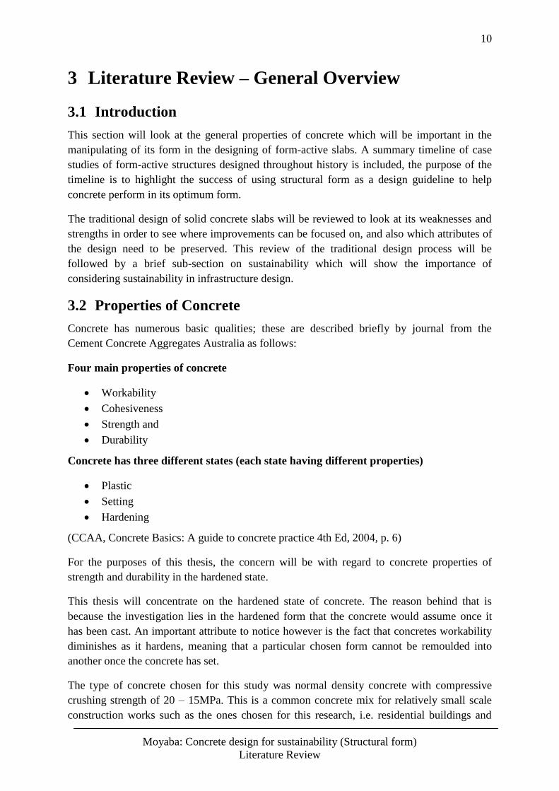
2.2.2 Bubble Deck Slabs
These slabs are also voided slabs. The difference relative to the above mentioned hollow core
slabs is that the voids are not one directional, they are spheres. Based on the tests done, these
types of slabs distribute the forces optimally in two directions as opposed to the one
directional hollow core slabs. In essence they negative in more or less the same way that solid
slabs behave, only with the added advantage that they are lighter. The hollow spheres used
have no added negative impact to the strength of the slabs (Călin, Gînţu, & Dascălu, 2009).
As noted in the previous section that one of the short fallings of the hollow core slab system
was the significant reduction in features such as shear resistance and fire resistance. Lai
explained that this caused an overall deterioration in the slabs structural integrity. However,
with regard to the Bubbkedeck® system, and according to the paper on Summary of Tests
and Studies Done Abroad on the Bubble Deck System: “The tests reveal that the shear
strength is even higher than presupposed. This indicates a positive influence of the balls.
Furthermore, the practical experience shows a positive effect in the process of concreting –
the balls cause an effect similar to plastification additives” (Călin, Gînţu, & Dascălu, 2009).
5
Moyaba: Concrete design for sustainability (Structural form)
Motivation for Study
Figure 1: Bubble deck slab (Source: Structural Engineers, Sustainability and Leed®)
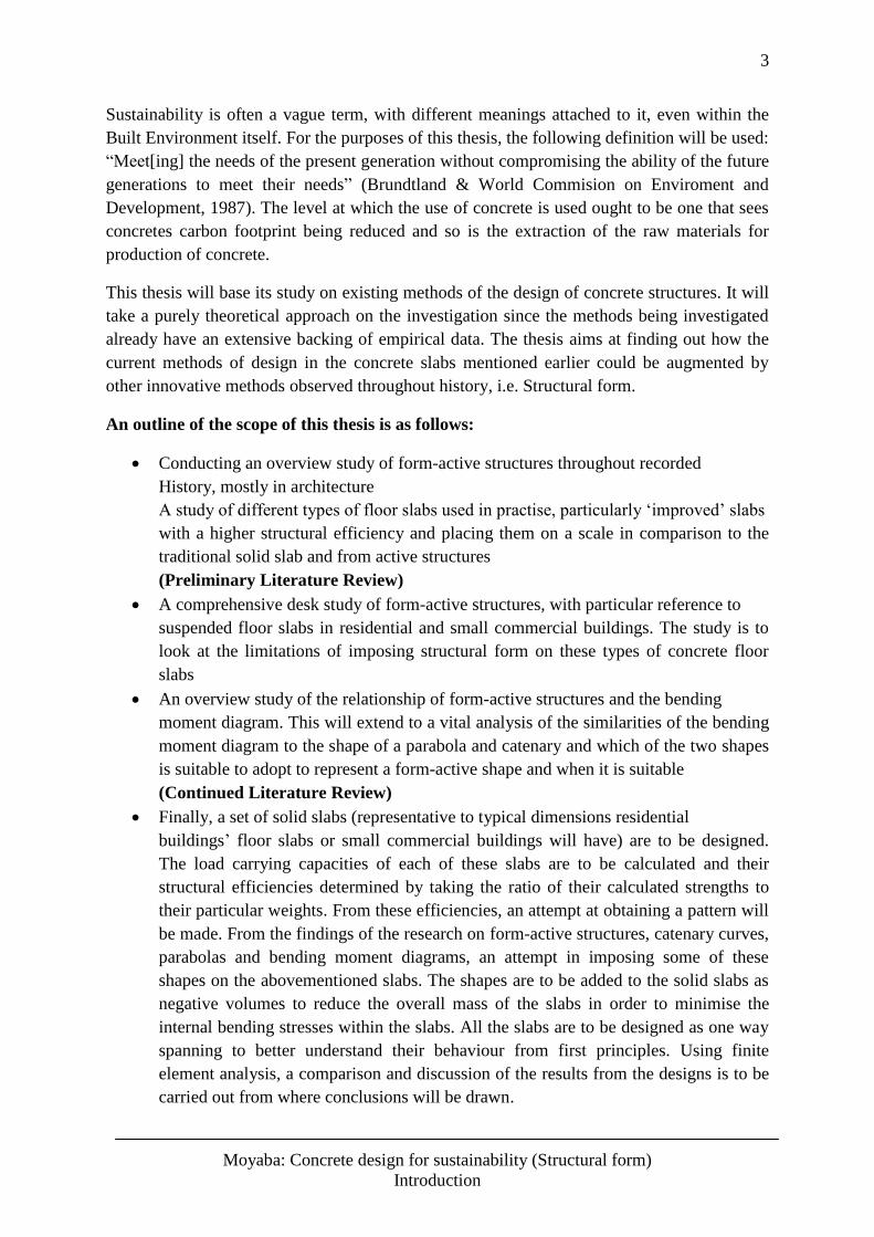
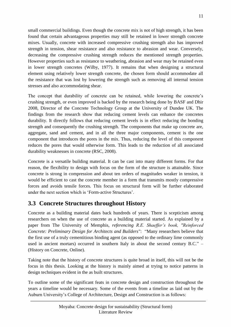
2.2.3 Holedeck Slabs
This slab system mimics that of a coffer/waffle slab. The innovation is in the reduction of
excess concrete within a traditional waffle slab. According to an e-portfolio on the holedeck
system, the system can achieve greater spans between supports due to its structural form.
Furthermore, the level of service is very high since the services are easily housed within the
depth of the slab itself. So this removes the need of suspended ceilings to hide services or
even HVAC systems. – (Holedeck the lean structure, online)
A comprehensive list of advantages this system offers is outlined in the abovementioned e-
portfolio for the holedeck system. These advantages include:
A reduction in built height
Less concrete consumption since passive concrete is removed
Total building’s weight reduction, giving a better structural performance
Reduction of building elements, e.g. no need for suspended ceilings, etc.
Reduction of implementation costs
With regard to the structural performance, the portfolio continues to explain that the lean
matrix structure improves the slab’s stiffness and the light weight also helps improve its
seismic performance, this is because in the event of a seismic event, a building with a lesser
total weight has less participation and is less vulnerable to collapse due to the horizontal
loadings of such a scenario. “Transmission of horizontal loads: the waffle slabs, like the rest
of bidirectional slabs, are more effective for horizontal requests than a unidirectional one.
Bending stiffness: the relative mass inertia of the section compared to the same area of a
concrete slab is 18 times bigger. Horizontal forces by earthquake: compared to a conventional
waffle slab Holedeck reduces its weight by around 15%. Therefore earthquake strengths are
reduced by approximately 8 to 10%.” (Holedeck®, 2013)
The following figures show the effect of slab geometry on the structural properties of slabs. It
can be seen how similar cross sectional areas, equivalent to same amount of material, can
drastically improve the structural integrity of a member if intelligent geometries are chosen.
Bubbledeck System
These are flat slabs similar to the hollow core slabs,
except that the hollow cores are not unidirectional but
are bidirectional. They are lightweight and because of
that they can span longer lengths than the conventional
solid flat slabs. Because of their inherent light weight
they have a lesser mass participation during seismic
events and are thus also structural efficient in that regard.
(Klane, 2007)
6
Moyaba: Concrete design for sustainability (Structural form)
Motivation for Study
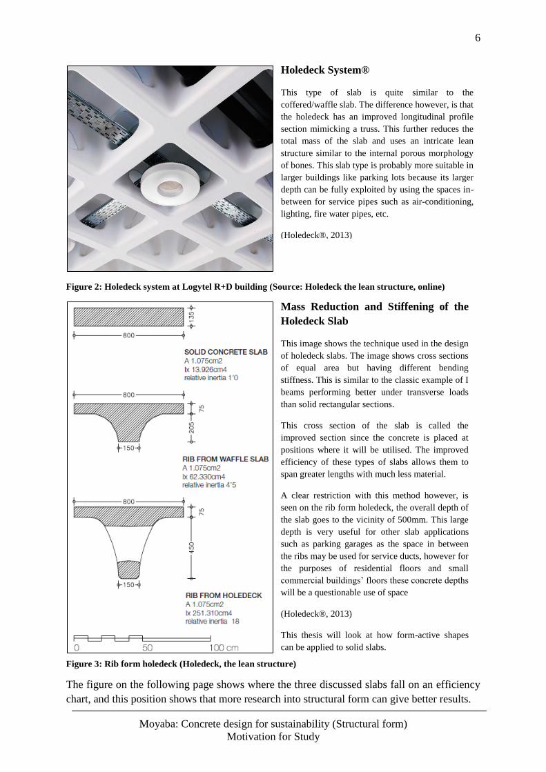
Figure 2: Holedeck system at Logytel R+D building (Source: Holedeck the lean structure, online)
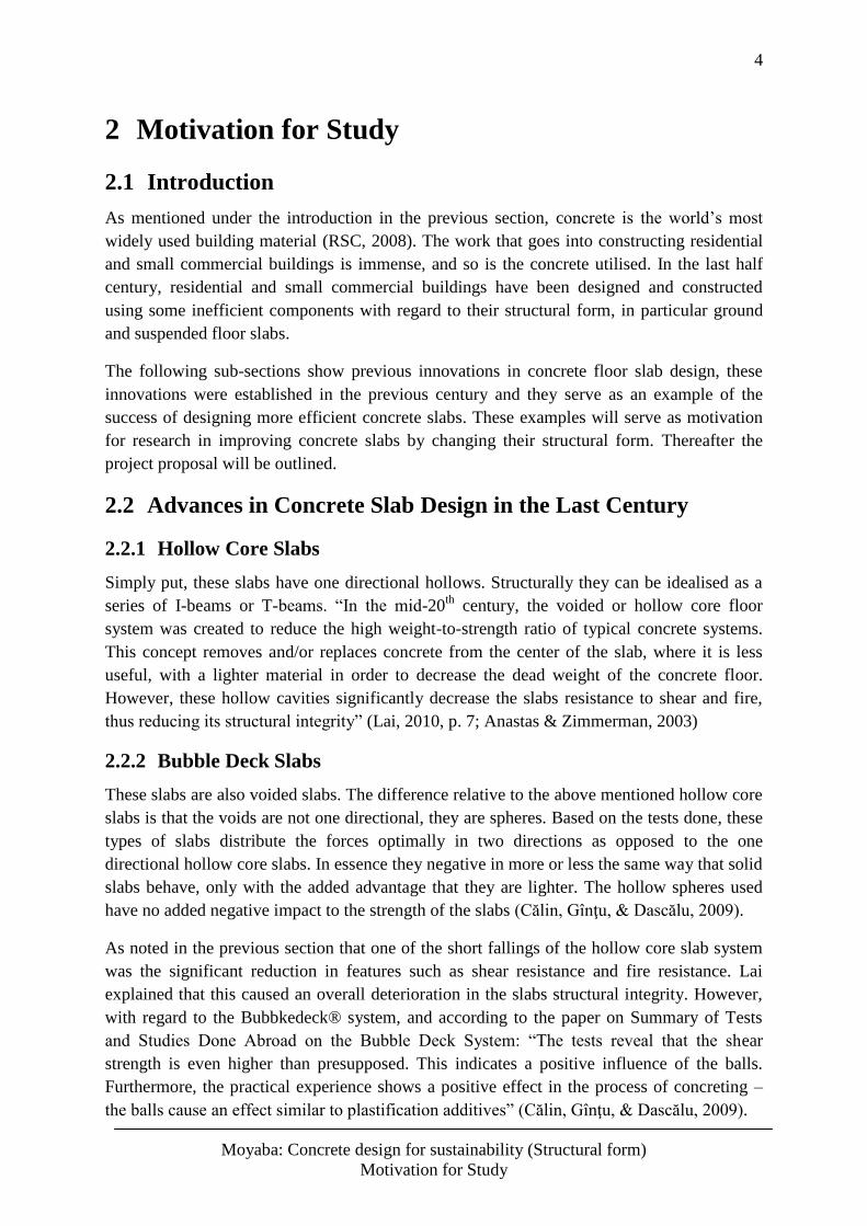
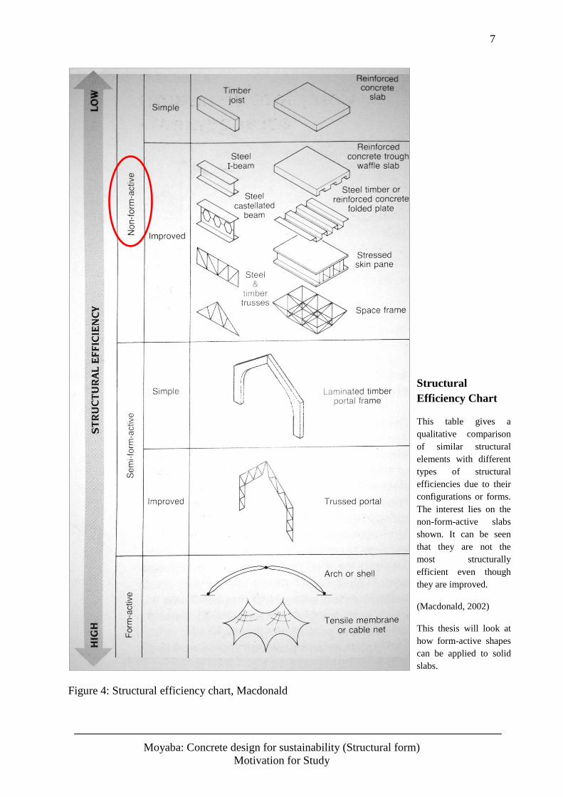
Figure 3: Rib form holedeck (Holedeck, the lean structure)
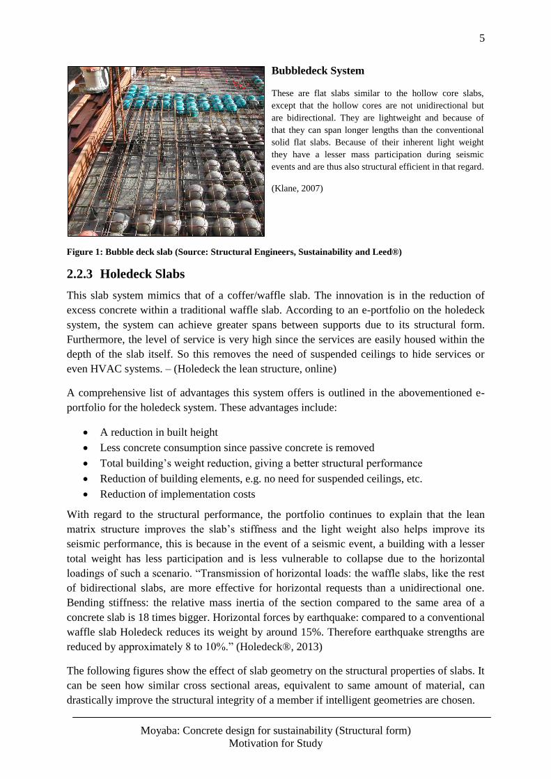
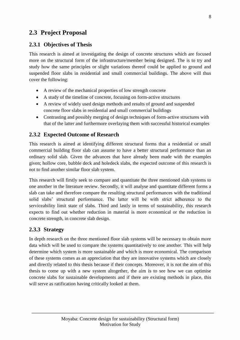
The figure on the following page shows where the three discussed slabs fall on an efficiency
chart, and this position shows that more research into structural form can give better results.
Holedeck System®
This type of slab is quite similar to the
coffered/waffle slab. The difference however, is that
the holedeck has an improved longitudinal profile
section mimicking a truss. This further reduces the
total mass of the slab and uses an intricate lean
structure similar to the internal porous morphology
of bones. This slab type is probably more suitable in
larger buildings like parking lots because its larger
depth can be fully exploited by using the spaces in-
between for service pipes such as air-conditioning,
lighting, fire water pipes, etc.
(Holedeck®, 2013)
Mass Reduction and Stiffening of the
Holedeck Slab
This image shows the technique used in the design
of holedeck slabs. The image shows cross sections
of equal area but having different bending
stiffness. This is similar to the classic example of I
beams performing better under transverse loads
than solid rectangular sections.
This cross section of the slab is called the
improved section since the concrete is placed at
positions where it will be utilised. The improved
efficiency of these types of slabs allows them to
span greater lengths with much less material.
A clear restriction with this method however, is
seen on the rib form holedeck, the overall depth of
the slab goes to the vicinity of 500mm. This large
depth is very useful for other slab applications
such as parking garages as the space in between
the ribs may be used for service ducts, however for
the purposes of residential floors and small
commercial buildings’ floors these concrete depths
will be a questionable use of space
(Holedeck®, 2013)
This thesis will look at how form-active shapes
can be applied to solid slabs.
7
Moyaba: Concrete design for sustainability (Structural form)
Motivation for Study
Figure 4: Structural efficiency chart, Macdonald
Structural
Efficiency Chart
This table gives a
qualitative comparison
of similar structural
elements with different
types of structural
efficiencies due to their
configurations or forms.
The interest lies on the
non-form-active slabs
shown. It can be seen
that they are not the
most structurally
efficient even though
they are improved.
(Macdonald, 2002)
This thesis will look at
how form-active shapes
can be applied to solid
slabs.
8
Moyaba: Concrete design for sustainability (Structural form)
Motivation for Study
2.3 Project Proposal
2.3.1 Objectives of Thesis
This research is aimed at investigating the design of concrete structures which are focused
more on the structural form of the infrastructure/member being designed. The is to try and
study how the same principles or slight variations thereof could be applied to ground and
suspended floor slabs in residential and small commercial buildings. The above will thus
cover the following:
A review of the mechanical properties of low strength concrete
A study of the timeline of concrete, focusing on form-active structures
A review of widely used design methods and results of ground and suspended
concrete floor slabs in residential and small commercial buildings
Contrasting and possibly merging of design techniques of form-active structures with
that of the latter and furthermore overlaying them with successful historical examples
2.3.2 Expected Outcome of Research
This research is aimed at identifying different structural forms that a residential or small
commercial building floor slab can assume to have a better structural performance than an
ordinary solid slab. Given the advances that have already been made with the examples
given; hollow core, bubble deck and holedeck slabs, the expected outcome of this research is
not to find another similar floor slab system.
This research will firstly seek to compare and quantitate the three mentioned slab systems to
one another in the literature review. Secondly, it will analyse and quantitate different forms a
slab can take and therefore compare the resulting structural performances with the traditional
solid slabs’ structural performance. The latter will be with strict adherence to the
serviceability limit state of slabs. Third and lastly in terms of sustainability, this research
expects to find out whether reduction in material is more economical or the reduction in
concrete strength, in concrete slab design.
2.3.3 Strategy
In depth research on the three mentioned floor slab systems will be necessary to obtain more
data which will be used to compare the systems quantitatively to one another. This will help
determine which system is more sustainable and which is more economical. The comparison
of these systems comes as an appreciation that they are innovative systems which are closely
and directly related to this thesis because if their concepts. Moreover, it is not the aim of this
thesis to come up with a new system altogether, the aim is to see how we can optimise
concrete slabs for sustainable developments and if there are existing methods in place, this
will serve as ratification having critically looked at them.
9
Moyaba: Concrete design for sustainability (Structural form)
Motivation for Study
2.3.4 Computer Aided Modelling
The use of computer software will be important to this thesis. No lab work is expected for the
purposes discussed thus far. The models are to be created and analysed while varying their
structural forms. The modelling here will be of a solid slab given shape modifications, and
with every different shape/form, the depth of the concrete will be varied to be able to
generate a report showing the impacts of structural form on the amount of material used. The
resulting behaviours are to be documented and reported in a way that allows comparing and
contrasting. From a discussion of these results with sustainability in mind, a conclusion will
be drawn.
2.4 Closure
The three examples of slabs discussed in this section all successfully reduce the amount of
concrete needed in their construction. The positive outcomes of optimising geometry are not
only with regard to sustainable design, they also improve the load carrying capacity of the
slabs, their spanning capabilities and in some cases such as the holedeck slab serviceability is
greatly increased because of the framework type structure which allows service ducts to be
easily installed and maintained (Holedeck®, 2013). The discussed slabs were improved by
mass reduction techniques.
Mass reduction techniques are useful and provide sound solutions; nonetheless they do not
produce the most structural efficient elements, as shown in figure 4. A more efficient element
takes advantage of the form which the structure as a whole assumes; therefore an in-depth
study on the behaviour of form-active structures is relevant to investigate how the structural
form of a slab can be manipulated to increase its structural efficiency, i.e. reducing the
amount of weight a slab needs in order to carry a given amount of loading.
Implementing structural form in the floor slab design answers the question of how structural
form can be used to contribute to a better solution. With respect to residential and small
commercial buildings, there are implicit restrictions in the freedom of designing with full
consideration of structural form, most obvious is the requirement that residential and small
commercial building floor slabs need to be flat on the top side, thus restricting the freedom of
adopting a true form-active shape. Another restriction is with regard to the slab depth; floor-
ceiling heights for these types of buildings typically range between 2.6m -3.0m, and thus it
would be a questionable use of space to have a slab taking up an equivalent amount of depth.
Designing compressive form-active structures is a less exact procedure compared to tensile
structures, i.e. tensile structures with no bending stiffness can re-adjust their shape to assume
new form-active shapes that accommodate the new load’s change, the converse does not hold
for compressive structures, particularly concrete. Since concrete becomes solid once it has
set, it cannot adopt a new form-active shape should the loading pattern change, thus the form-
active shape chosen may not remain truly the form-active shape. These and more constraints
are to be looked at into detail in this thesis with the aim of finding out ways of how form may
give better solutions given all its constraints in the chosen application of residential and small
commercial buildings’ floor slabs.
10
Moyaba: Concrete design for sustainability (Structural form)
Literature Review
3 Literature Review – General Overview
3.1 Introduction
This section will look at the general properties of concrete which will be important in the
manipulating of its form in the designing of form-active slabs. A summary timeline of case
studies of form-active structures designed throughout history is included, the purpose of the
timeline is to highlight the success of using structural form as a design guideline to help
concrete perform in its optimum form.
The traditional design of solid concrete slabs will be reviewed to look at its weaknesses and
strengths in order to see where improvements can be focused on, and also which attributes of
the design need to be preserved. This review of the traditional design process will be
followed by a brief sub-section on sustainability which will show the importance of
considering sustainability in infrastructure design.
3.2 Properties of Concrete
Concrete has numerous basic qualities; these are described briefly by journal from the
Cement Concrete Aggregates Australia as follows:
Four main properties of concrete
Workability
Cohesiveness
Strength and
Durability
Concrete has three different states (each state having different properties)
Plastic
Setting
Hardening
(CCAA, Concrete Basics: A guide to concrete practice 4th Ed, 2004, p. 6)
For the purposes of this thesis, the concern will be with regard to concrete properties of
strength and durability in the hardened state.
This thesis will concentrate on the hardened state of concrete. The reason behind that is
because the investigation lies in the hardened form that the concrete would assume once it
has been cast. An important attribute to notice however is the fact that concretes workability
diminishes as it hardens, meaning that a particular chosen form cannot be remoulded into
another once the concrete has set.
The type of concrete chosen for this study was normal density concrete with compressive
crushing strength of 20 – 15MPa. This is a common concrete mix for relatively small scale
construction works such as the ones chosen for this research, i.e. residential buildings and
11
Moyaba: Concrete design for sustainability (Structural form)
Literature Review
small commercial buildings. Even though the concrete mix is not of high strength, it has been
found that certain advantageous properties may still be retained in lower strength concrete
mixes. Usually, concrete with increased compressive crushing strength also has improved
strength in tension, shear resistance and also resistance to abrasion and wear. Conversely,
decreasing the compressive crushing strength reduces the mentioned strength properties.
However properties such as resistance to weathering, abrasion and wear may be retained even
in lower strength concretes (Wilby, 1977). It remains that when designing a structural
element using relatively lower strength concrete, the chosen form should accommodate all
the resistance that was lost by lowering the strength such as removing all internal tension
stresses and also accommodating shear.
The concept that durability of concrete can be retained, while lowering the concrete’s
crushing strength, or even improved is backed by the research being done by BASF and Dhir
2008, Director of the Concrete Technology Group at the University of Dundee UK. The
findings from the research show that reducing cement levels can enhance the concretes
durability. It directly follows that reducing cement levels is in effect reducing the bonding
strength and consequently the crushing strength. The components that make up concrete are,
aggregate, sand and cement, and in all the three major components, cement is the one
component that introduces the pores in the mix. Thus, reducing the level of this component
reduces the pores that would otherwise form. This leads to the reduction of all associated
durability weaknesses in concrete (RSC, 2008).
Concrete is a versatile building material. It can be cast into many different forms. For that
reason, the flexibility to design with focus on the form of the structure is attainable. Since
concrete is strong in compression and about ten orders of magnitudes weaker in tension, it
would be efficient to cast the concrete member in a form that transmits mostly compressive
forces and avoids tensile forces. This focus on structural form will be further elaborated
under the next section which is ‘Form-active Structures’.
3.3 Concrete Structures throughout History
Concrete as a building material dates back hundreds of years. There is scepticism among
researchers on when the use of concrete as a building material started. As explained by a
paper from The University of Memphis, referencing R.E. Shaeffer’s book, "Reinforced
Concrete: Preliminary Design for Architects and Builders": “Many researchers believe that
the first use of a truly cementitious binding agent (as opposed to the ordinary lime commonly
used in ancient mortars) occurred in southern Italy in about the second century B.C.” –
(History on Concrete, Online).
Taking note that the history of concrete structures is quite broad in itself, this will not be the
focus in this thesis. Looking at the history is mainly aimed at trying to notice patterns in
design techniques evident in the as built structures.
To outline some of the significant feats in concrete design and construction throughout the
years a timeline would be necessary. Some of the events from a timeline as laid out by the
Auburn University’s College of Architecture, Design and Construction is as follows:
12
Moyaba: Concrete design for sustainability (Structural form)
Literature Review
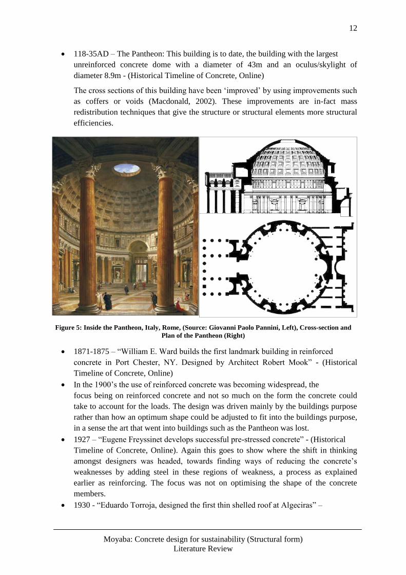
118-35AD – The Pantheon: This building is to date, the building with the largest
unreinforced concrete dome with a diameter of 43m and an oculus/skylight of
diameter 8.9m - (Historical Timeline of Concrete, Online)
The cross sections of this building have been ‘improved’ by using improvements such
as coffers or voids (Macdonald, 2002). These improvements are in-fact mass
redistribution techniques that give the structure or structural elements more structural
efficiencies.
Figure 5: Inside the Pantheon, Italy, Rome, (Source: Giovanni Paolo Pannini, Left), Cross-section and
Plan of the Pantheon (Right)
1871-1875 – “William E. Ward builds the first landmark building in reinforced
concrete in Port Chester, NY. Designed by Architect Robert Mook” - (Historical
Timeline of Concrete, Online)
In the 1900’s the use of reinforced concrete was becoming widespread, the
focus being on reinforced concrete and not so much on the form the concrete could
take to account for the loads. The design was driven mainly by the buildings purpose
rather than how an optimum shape could be adjusted to fit into the buildings purpose,
in a sense the art that went into buildings such as the Pantheon was lost.
1927 – “Eugene Freyssinet develops successful pre-stressed concrete” - (Historical
Timeline of Concrete, Online). Again this goes to show where the shift in thinking
amongst designers was headed, towards finding ways of reducing the concrete’s
weaknesses by adding steel in these regions of weakness, a process as explained
earlier as reinforcing. The focus was not on optimising the shape of the concrete
members.
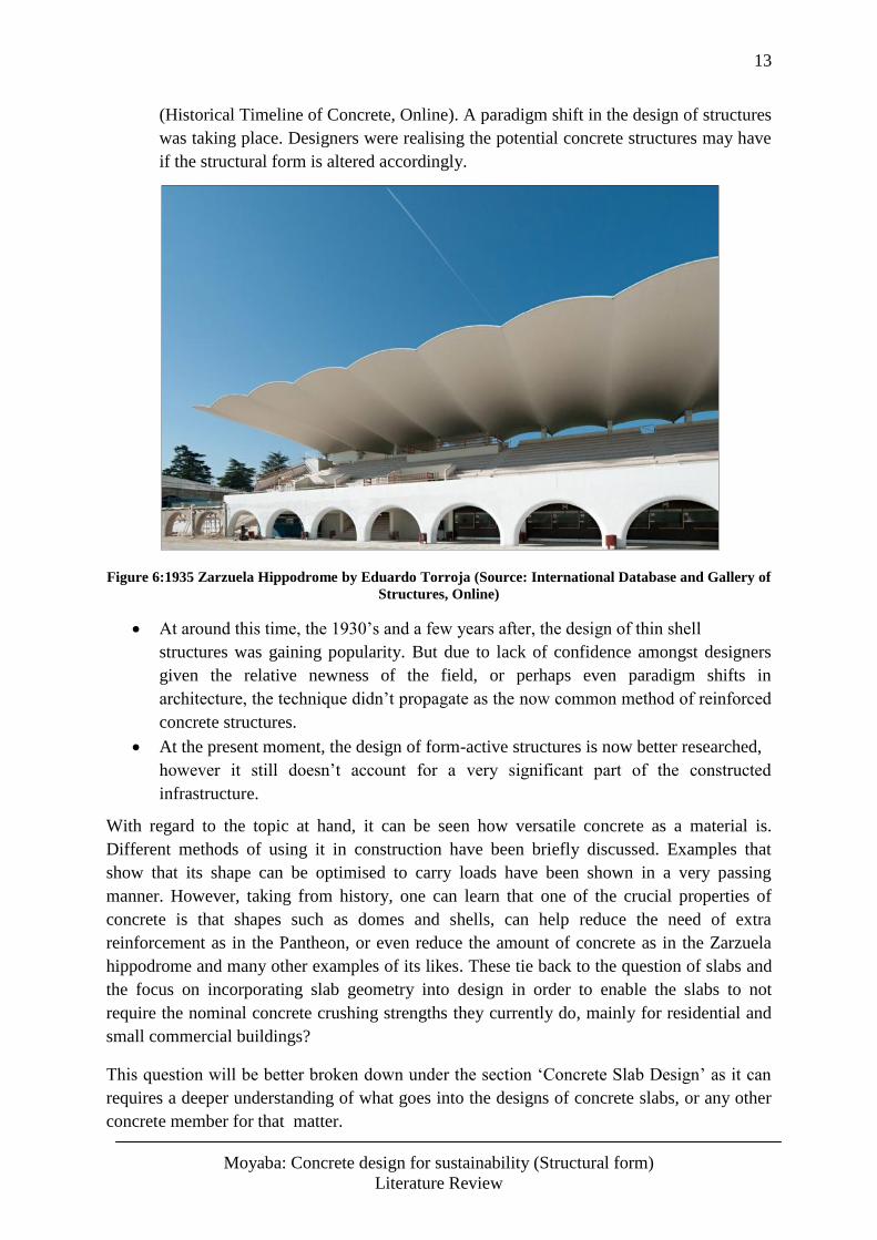
1930 - “Eduardo Torroja, designed the first thin shelled roof at Algeciras” –
13
Moyaba: Concrete design for sustainability (Structural form)
Literature Review
(Historical Timeline of Concrete, Online). A paradigm shift in the design of structures
was taking place. Designers were realising the potential concrete structures may have
if the structural form is altered accordingly.
Figure 6:1935 Zarzuela Hippodrome by Eduardo Torroja (Source: International Database and Gallery of
Structures, Online)
At around this time, the 1930’s and a few years after, the design of thin shell
structures was gaining popularity. But due to lack of confidence amongst designers
given the relative newness of the field, or perhaps even paradigm shifts in
architecture, the technique didn’t propagate as the now common method of reinforced
concrete structures.
At the present moment, the design of form-active structures is now better researched,
however it still doesn’t account for a very significant part of the constructed
infrastructure.
With regard to the topic at hand, it can be seen how versatile concrete as a material is.
Different methods of using it in construction have been briefly discussed. Examples that
show that its shape can be optimised to carry loads have been shown in a very passing
manner. However, taking from history, one can learn that one of the crucial properties of
concrete is that shapes such as domes and shells, can help reduce the need of extra
reinforcement as in the Pantheon, or even reduce the amount of concrete as in the Zarzuela
hippodrome and many other examples of its likes. These tie back to the question of slabs and
the focus on incorporating slab geometry into design in order to enable the slabs to not
require the nominal concrete crushing strengths they currently do, mainly for residential and
small commercial buildings?
This question will be better broken down under the section ‘Concrete Slab Design’ as it can
requires a deeper understanding of what goes into the designs of concrete slabs, or any other
concrete member for that matter.
14
Moyaba: Concrete design for sustainability (Structural form)
Literature Review
3.4 Traditional Concrete Slab Design Process
3.4.1 Ultimate Limit State Design
This method of design considers the worst loading case scenario that could be imposed on a
structure during its assumed lifetime. The scenario is called the ultimate limit state (ULS). It
includes numerous safety factors, some of which are embedded in the design equations.
These safety factors are applied on the dead load of the structure, which is the structures own
self weight and secondly the factors are applied on the live/variable loading that will be
applied on the structure. The latter is the weight that the structures primary function is to
support.
(1)
Equation 1: Ultimate load equation, SANS 0100-1
Where n = load, Gn = Dead load, Qn = Live load, SANS 0100-1.
Based on the heavily factored ultimate load, giving the ultimate design moments, the section
is designed using a series of design equations which give the ‘optimum’ cross section, the
allowable span and the required minimum steel reinforcing bars required. Emphasis here is
on the ‘optimum’ cross section.
As discussed notably a few times earlier in this paper, concrete is significantly weaker in
tension, more precisely, to the order of roughly 10 times. Thus, a concrete with crushing
strength of 30MPa will most likely have about 3MPa tensile strength. As mentioned in
section 3.3.1, one of the inherent deficiencies in the design of RC structures which carry
transverse loads, is that they are designed to crack in the tension zones. This allowance is to
trigger the tension steel reinforcing to carry the tensile forces. Altogether, that renders the
concrete in the tension zone obsolete. However it is no coincidence that the concrete in the
tension zone carries no load, it is one of the fundamental assumptions in this design
procedure.
This fundamental assumption carries the bulk of the inefficiency in the design process of
slabs. If the concrete adds no structural worth except for the dead load, it would be an
excellent improvement in the design to safely remove this concrete. This reduction will result
in the reduction of the dead load. In most cases the dead load of residential floor slabs and
small commercial buildings’ floor slabs account for over 50% of the total carried load.
Therefore this particular improvement will most likely improve the structural efficiency of
these slabs.
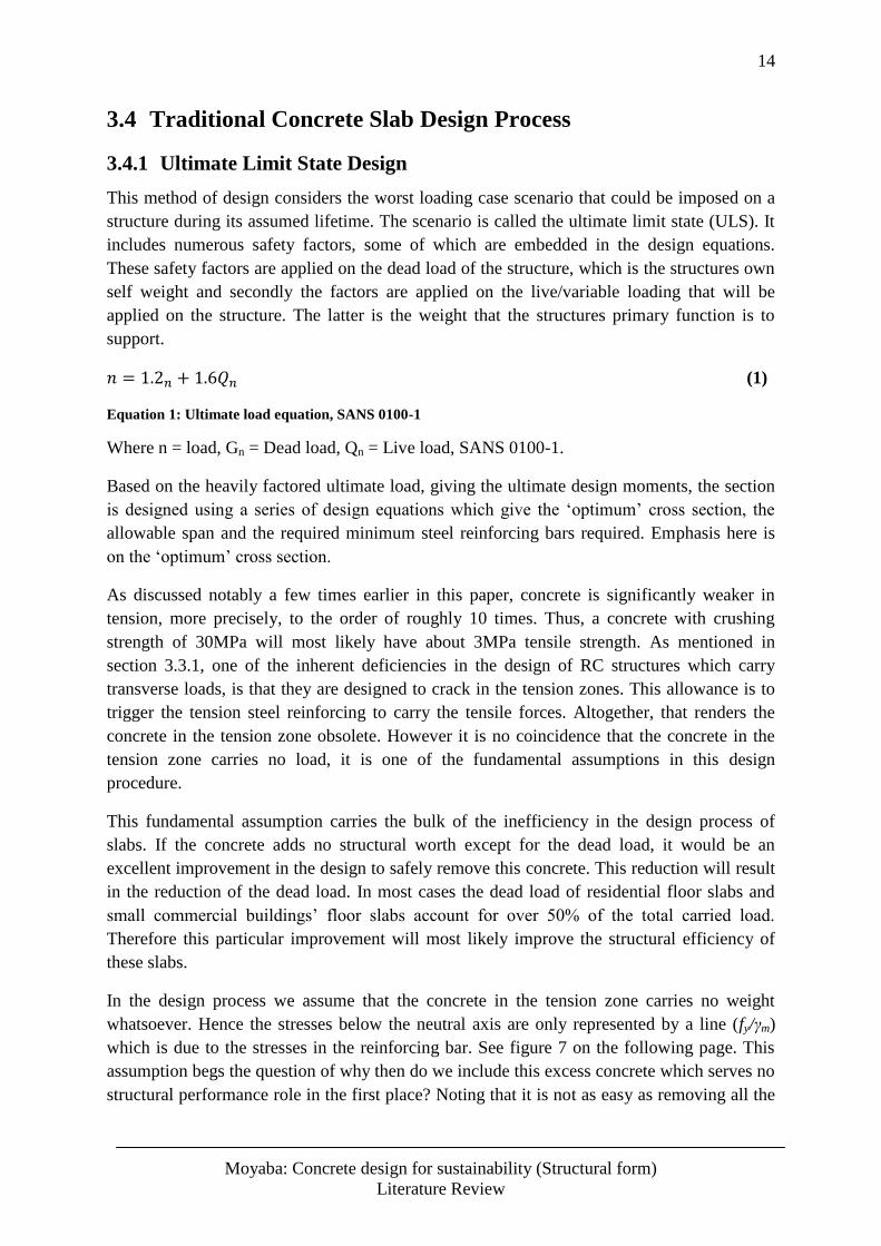
In the design process we assume that the concrete in the tension zone carries no weight
whatsoever. Hence the stresses below the neutral axis are only represented by a line (fy/γm)
which is due to the stresses in the reinforcing bar. See figure 7 on the following page. This
assumption begs the question of why then do we include this excess concrete which serves no
structural performance role in the first place? Noting that it is not as easy as removing all the
15
Moyaba: Concrete design for sustainability (Structural form)
Literature Review
tension concrete since the tension forces will simply redistribute themselves in the remaining
concrete, leading to an looped problem with no solution.
Figure 7: Actual and equivalent stress distribution at failure. (Source: SABS 0100-1: 4.3.3.3)
This particular problem has led to innovations such as the hollow core slabs, Bubble deck
slabs and Holedeck slabs, all of which will be reviewed in section 3.5. This research however
seeks to employ a different approach which considers changing the entire structures form.
3.4.2 Serviceability Design
This part of the design of RC structures seeks to ensure that the structure performs all its
functions during its lifetime adequately. Deflections have to be minimised, the structure has
to be stable, and cracks have to be controlled and so on. These are all encompassed within the
SLS, the serviceability limit state.
If the structural form of the entire structure is to be looked at as a whole, it ought to be
appreciated that serviceability limitations will be imposed. Some structural forms are
structurally superior to others, but these forms may easily defeat the purposes of the structure
if utilised. An example may be taken from a piece of A4 paper or a similar sized paper.
Holding the paper horizontally from one end alone, the paper will surely collapse. However,
adding a curvature to the paper will allow it to remain horizontal and not collapse while still
being held at one end.
A similar scenario may be researched for slabs, and similar results may be realised. Be that as
it may, it would be poor design to make a slab that is heavily curved because its purpose
amongst others is to hold furniture and other household appliances, all of which need flat
horizontal surfaces to rest on. There is also a level of comfort that needs to be maintained,
people are more likely to be comfortable in a building with relatively flat slabs as opposed to
curvy slabs. All of this factors fall directly under the SLS design and thus in further research
the considerations of SLS design need to be prudently followed.
16
Moyaba: Concrete design for sustainability (Structural form)
Literature Review
3.5 Concrete Slab Design for Suspended Slabs
Design of reinforced concrete (RC) structures is a well-documented procedure. As a result
many countries have their own set of standards which serve as design guidelines for RC
structures. As mentioned earlier in the introduction, the procedures differ from country to
country and even amongst different states in some places. This is due to different climatic
conditions which affect the durability of the concrete such as corrosive environments. Other
factors that influence the differences in the design standards are preferences in calculation
methods. However, these differences will not be accounted for in this thesis since the aim is
not to scrutinise the available standards but to investigate how the form of concrete slabs
could be optimised to allow for a possible reduction in the concrete strength, or more
commonly the amount of materials used.
The design procedure of a concrete structure i.e. member sizing can be summarised as
follows; the member’s cross section is determined by calculating adequate areas of concrete
and steel, the steel being important for the tension forces generated due to the moment within
the cross section. This definition encompasses the methodology followed in the design of RC
slabs. A section of a slab is taken, which would usually be treated like a beam, and from that
section an external moment is calculated form the given loading. This method of slab design
assumes that all concrete in the tension zone does no work in carrying the tensile forces,
moreover this concrete is often more than half the total concrete. Clearly this is a major
unsustainable use of material.
For this reason that the design procedures focus on the member’s cross section, it is therefore
a region of interest where some innovations looked at for weaknesses in the current
traditional methods of design. Successful attempts on how they could reduce excess concrete
and only have it where it is absolutely needed were made. This has resulted in shedding of
significant amounts dead loads. Consequently that has successfully improved even the
structural performances of members which have been designed with these considerations.
As a prerequisite to the design of RC structures, the loads to be carried by the structure ought
to be calculated. Again, there are many methods available to deal with this. These methods
will not be discussed here as they are a topic by themselves. Nonetheless, it is noteworthy
that the methods to be assumed in this paper are for elastic analysis of slabs since slabs fail in
either crushing or by shear failure as opposed to yielding. This means that the design
procedure will concentrate on elastic design of RC slabs and not the elastic design.
17
Moyaba: Concrete design for sustainability (Structural form)
Literature Review
3.5.1 Inherent Inefficiencies in Solid Slab Design
Since reinforced concrete elements are designed for either axial stresses, shear stresses or
bending stresses it is necessary to understand the influences of each case. For beams and/or
slabs, the loads are usually applied transverse to the element, this causing both bending and
shear stresses within the cross section; this puts the concrete in a position where it cannot act
efficiently without assistance. The bending moments cause a distribution of both compression
and tension in the cross section, thus putting a significant amount of concrete under tension
where it is naturally weaker. Most commonly the assistance of the concrete in tension is
provided by reinforcing steel, however a major deficiency in this method is that traditionally
the concrete under tension is left there and adds no structural worth besides adding more
weight while the steel is designed to carry all the tensile forces.
In the design of RC slabs or beams, it is assumed that for serviceability design the section is
uncracked while it cracks under ultimate loading. According to how the design of the beam or
slab was done there are mainly three ways that it could fail; sudden failure, failure with prior
warning and combined steel and concrete failure. The traditional RC design of these elements
has the advantage of having a control over how the element fails should the load exceed the
ultimate one of a concrete member. Nonetheless the design does not focus on mitigating the
weaknesses that arise due to carrying a transverse load; for the most part it focuses on
strengthening the weaknesses that arise because of the transverse loads but it seldom focuses
on removing these weaknesses. A unique solution to this will be discussed in the analytical
methodology section which converts the moment into forces by introducing a lever arm
outside the cross section.
In the calculation of ultimate limit state (ULS) loads as discussed in 3.4.1, the dead load has a
lesser partial factor that the live loading, it seldom happens that the live load exceeds the self-
weight of the beam or slab, see equation (1). That is the cause of an inherited low efficiency.
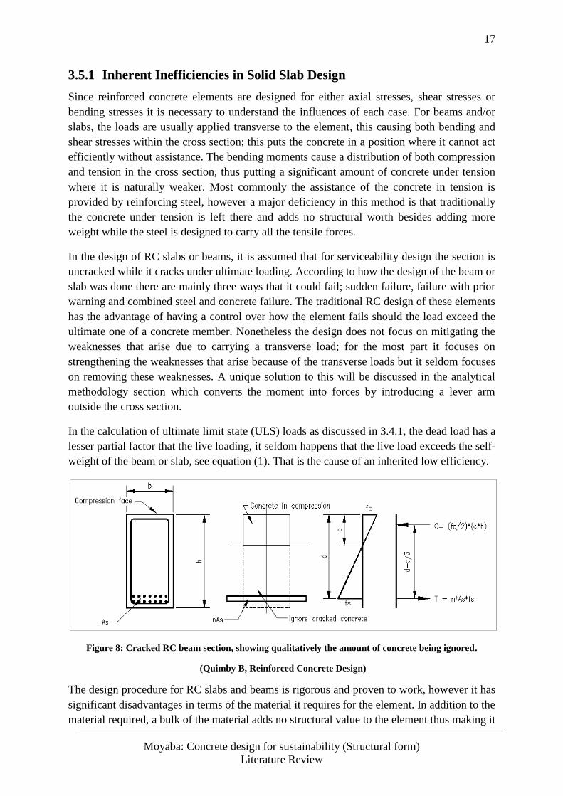
Figure 8: Cracked RC beam section, showing qualitatively the amount of concrete being ignored.
(Quimby B, Reinforced Concrete Design)
The design procedure for RC slabs and beams is rigorous and proven to work, however it has
significant disadvantages in terms of the material it requires for the element. In addition to the
material required, a bulk of the material adds no structural value to the element thus making it
18
Moyaba: Concrete design for sustainability (Structural form)
Literature Review
inefficient. Thus Improvements of the concrete’s strength are likely to have no major impact
on structures designed with this underlying assumption of the ignored cracked concrete. Due
to the amount of concrete utilised for caring the compression forces, increasing the concrete’s
crushing strength has a reduced improving effect, particularly to beams and slabs. As can be
seen in the image above, the concrete that carries the compressive load is indicated, this
concrete accounts for less than half the section. Therefore improvements on the concrete’s
crushing strength are lost in the concrete that carries no load.
3.5.2 Advantages of Solid Slab Design
Introducing improvements to the traditional slab design ought to consider both the
weaknesses of the traditional methods as well as its advantages. The importance of including
the advantages is to ensure that improving the design or making it more efficient in this case
does not remove the favourable attributes of the traditional methods. Thus any improvement
should in effect build on the current positive attributes.
The advantages carried by the traditional slab design as briefly mentioned in the previous
section is that of the flexibility in deciding the failure modes. Depending on the designer’s
preference, the beam/slab can be designed as follows;
Over reinforced section
This type of design is generally not preferred since the failure mode is sudden and thus puts
the people using the structure in danger. The concrete reaches crushing strength and ruptures
early before the steel could reach its yield strength. There is therefore no prior warning for
impeding failure.
Under reinforced section
This is probably a safer design since failure is noticeable before it actually happens. The steel
reaches yield strength before the concrete crushes thus large deformations will be visible thus
giving clear signs of impending failure.
Balanced section
This is a less practical design because predicting the equivalent behaviours of both the
concrete and steel simultaneously is not an exact procedure.
These advantages are carried by the traditional design procedures of reinforced concrete slabs
or beams. They are of a high importance since they give a measure of control in the
behaviour of the constructed structure and consequently give a certain guarantee on the
structure serving its purpose to a measurable degree of safety. This is important to consider in
this thesis because in trying to consider structural form in the design of slabs, a degree of
safety needs to be considered. Therefore the mentioned advantages of the solid slab design
need to be considered in weighing the pros and cons of the traditional slab design to those of
form-active slabs.
19
Moyaba: Concrete design for sustainability (Structural form)
Literature Review
3.6 Concrete Slab Design for ‘Slab-on-Grade’
The design of ground floor slabs (Slabs-on-grade) is considered in this thesis for a measure of
completeness as the problem of inefficient structural members includes most if not all
structural elements. Slabs-on-grade however are a unique exception since their support
conditions are continuous. The focus in the design of slabs on grade is usually on the grade
that they are cast on, making this founding conditions string enough is usually a first priority
and depending on how strong the grade is, the concrete utilised may be of a lower crushing
strength.
Slabs on grade also support immense transverse loads, however the transverse loads can be
assumed to be axial loads, this is because the ground is continuous under the slab and thus all
internal forces generated will most likely be of the axial kind, making the slabs performance
efficient since the slab will be in full compression. However this assumption may be
misleading due to the dynamic nature of the ground. Issues such as differential settlement
caused by cyclic movements between dry and wet seasons may create zone where the slabs
acts as a suspended slab, which would pose a significant danger should the slab be of a lower
crushing strength, nonetheless the failure of the slab may not be as fatal as that of the
suspended slab due lower potential energy. This danger due to the dynamic nature of the
ground may well be considered a topic for the strength of the grade.
Another factor that may cause slabs on grade to have similar properties as suspended floor
slabs is the membrane effect that the slab has on the ground immediately below it. This
membrane effect simply creates a seal for all the dampness in the grade below the slab. The
water in the grade will no longer be able to evaporate, thus causing a swelling in the ground.
The problem arises because the grade at the edges is able to let off some of the dampness thus
shrinks during dry seasons while the middle part remains swollen. The effect that this
scenario has is that the slab will then be equivalent to a cantilever slab thus requiring more
bending stiffness than it was designed to have (CCAA, Guide to Residential Floors, 2003).
In the event of external loading, slabs on grade are not always designed to be structurally
active. This is explained better by the Concrete Steel Reinforcement Institute’s (CSRI’s)
report on reinforcing in slabs on grades. One of the advantages of having steel reinforcing or
welded wire mesh is gaining structural strength after cracking during overloading. “When
overloading occurs, such that the cracking moment limit of the concrete slab has been
exceeded, structural cracks may occur. The steel will then act as structural reinforcement and
provide moment capacity according to normal, cracked-section, reinforced concrete theory.
This concept may also be intentionally used in the original design concept of the slab; that is,
designing the slab to have structurally-active reinforcement under externally applied
loadings.” (CRSI, 1998)
The above implies that trying to optimise structural form for this slab application may yield
results that may not be significant enough. In the design of suspended slabs, we look to the
procedure of the design to try look for ways to optimise the geometry. With slabs-on-grade
not so much attention is given to designs for flexure because it is minimal.
20
Moyaba: Concrete design for sustainability (Structural form)
Literature Review
3.7 Sustainable Design
Sustainable design with regard to concrete construction can be achieved in a number of ways.
More commonly this can be achieved by physical reduction in material used. This is
characteristic to the three slab systems discussed earlier. Sustainability in all the three cases
was mainly derived from the reduction of material used. This of course triggers a trickledown
effect whereby other sustainability milestones are achieved such as better thermal insulation
and high levels of services.
On the other hand, significantly reducing concrete crushing strengths from the nominal 20-
25MPa strengths might bring out another level of sustainability as it is directly related to
reductions in cement that goes into the concrete mixture, consequently reducing the total
carbon footprint directly from slab constructions in residential and small commercial
buildings.
This thesis is concerned with both the reduction of material used and the reduction of the
amount of cement in slabs. Designing concrete slabs using structural form implies that the
slabs are designed to act almost entirely in compression. When concrete acts in compression,
the effect of lowering or increasing the concrete’s crushing strength, i.e. decreasing or
increasing the cement content in the mixture, has a direct and sensitive effect on the
performance of the concrete. As mentioned earlier under section 3.5.1, changing the cement
content for the traditional slab has a reduced effect due to the ignored concrete, for the form-
active slab however the effects are expected to be high. In simpler terms, form-active slabs
are aimed at using lesser material, and also being able to perform at lower crushing strengths
because of their ability to act in compression.
As underlined by Anastas and Zimmerman in The 12 Principles of Green Engineering;
Principle 5 explains that for sustainability a product that is designed ought to be output pulled
rather than input pushed. This is directly related to the structural efficiency of slabs.
Traditional slabs have a low efficiency below one, this shows that the weight carried by the
slabs are mostly from their own weights as opposed to the live loads they are designed to
carry. The implementing of structural form will help make the slabs more output pulled by
making them have much lesser weight than the traditional solid slabs carrying an equivalent
live load, thus taking their structural efficiencies higher. Principle 8 explains that design for
unnecessary capacity or capability ought to be avoided, the so called “one size fits all”
designs (Anastas & Zimmerman, 2003). This principle is directly related to the design
process of form-active structures as a whole and can serve as relevant motivation in pursuing
such designs to attain sustainable development. Design of form-active structures comprises of
the study of the load to be carried and analysing what shape the structure requires for the
most efficient way of carrying that load, i.e. the solution is a tailored solution specifically
meant for that particular loading scenario, moreover the solution considers the type of
material that will be used to construct the structure, i.e. tensile material with no bending
stiffness or rigid material with bending stiffness as in concrete. The implementation of
structural form in the design of slabs can thus be said to be in line with sustainable
development as it follows the relevant guidelines as highlighted.
21
Moyaba: Concrete design for sustainability (Structural form)
Literature Review
3.8 Closure - Main Findings from Literature
The investigation of ways to optimise the structural form of slabs is a fairly new field that has
been a topic of research in the last century, basing its methods on other form-active structures
such as bridges and larger structures. However, the design of traditional slabs is a well-
established craft. Ground-breaking innovations have already been made, all of which have
one eminent feature in common, and that is the removing of ‘passive’ concrete from the slab
itself. The focus has been in the internal structure or cross section of the slab rather than the
slab as a whole. This has been a fruitful focal point as it has yielded successful results.
Further research could be focused on how the structure as a whole can be in a form which is
structurally more superior to the traditional solid slab. This is aimed at finding out if at all the
overall shapes of slabs can be altered to enhance their structural performance and allow lower
concrete strengths to be used. Still, this has to be with close adherence to serviceability limits
of slabs in general as their function is the governing factor on whether they will be able to
perform their duties.
With regard to slabs-on-grade, there is little room for optimisation since the strength of these
slabs is lower than that of suspended slabs. This is due to the fact that slabs-on-grade seldom
experience high deflections or moments as they sit directly on a well compacted subgrade
which directly receives the loading the slab experiences. For this reason, this thesis will not
focus on slabs on grade. The focus will be on roof slabs and suspended floor slabs as these
slabs experience larger transverse loads and will benefit more from increased efficiencies.
From the review on the traditional solid slab design it was found that the major factor that
gives the traditional solid slab its inefficiency is the ignored cracked concrete when designing
the solid slabs. This concrete that carries no load is where the recent slab innovations are
focusing on for mass reduction. The recent slab innovations, i.e. hollow core slabs, hollow bi-
directional slabs and improved waffle slabs have an increased efficiency when compared to
the traditional solid slab, however, they are still not entirely efficient on a scale which
compares types of structures. This motivates this thesis’s proposal to investigate structural
form as a design guideline for designing residential and small commercial building concrete
slabs, i.e. form-active structures were shown to potentially be the most efficient structures.
With regard to sustainability an overview of the impact of changing the concrete’s crushing
strengths on the traditional slabs showed that because of the underlying assumption of
ignoring the cracked concrete, the effects are reduced. For form-active slabs however, the
effects of changing the concrete’s crushing strength are significant since the concrete is
almost entirely in compression. Therefore designing the slabs by considering structural form,
the effects of the concrete’s crushing strength can be augmented and hence lower strengths
may be used. Furthermore, a higher structural efficiency can be achieved, thus using less
material to carry more load. These characteristics of designing form-active structures are
integral to sustainable development, this is shown in The 12 Principles of Green Engineering
by Anastas and Zimmerman.
22
Moyaba: Concrete design for sustainability (Structural form)
Form-Active Structures
4 Design of Form-Active Structures
4.1 Introduction
The design of form-active structures requires a critical analysis of the load to be carried and
the form/shape that that particular load requires for an efficient performance. Simply put, this
type of design requires a regressive technique which analyses the type of load and the form
the load would generate on a zero stiffness member. This shape is then translated to the
structures form. This section is aimed at outlining the procedure for designing these structures
so that the procedure can be applied to residential and small commercial buildings’ roof and
suspended floor slabs.
The formation of a form-active structure has to include three major factors that determine the
success or failure in designing such a structure. These factors are; rigidity, element
shape/form-active shape and load pattern. Depending on these three major determining
factors, the shape can then be deemed either non form-active, semi form-active or fully form-
active. This section will explain each of these three factors and how they influence whether or
not a structure is form-active, this analogy is based on the book Structure and Architecture by
MacDonald A.J. alongside the case studies from the books Why Buildings Stand Up and
Why Buildings Fall Down by Salvadori et.al.
4.2 Rigidity of the Element
The rigidity of a structural element has a major bearing on what type of loads that structure
can support but more importantly how that structure will support the load. Non rigid
structural elements have the capacity to change their shape in order to support imposed loads.
A classic example is the string; it has no bending resistance and furthermore cannot support
compressive loads. A string can support tensile forces alone. The method in which the string
will support tensile loads depends on its support conditions; clearly a string supported on one
end alone will not change its shape under loading except of course for the elongation that
may occur. However, a string supported on more than one support and under transverse
loading will assume a shape that will allow it to convert the load into internal forces similar
to that of a string supported on one end under loading. This is one of the key concepts of
form-active structures i.e. checking what shape a member with no bending stiffness assumes
under a load with a certain magnitude characteristic (point loads or uniformly distributed
loads).
Tensile members with no bending stiffness are a special case because they are able to change
their shapes with changing load magnitudes and pattern assuming no failure at this point.
Compression members on the other hand pose a notable challenge since they are rigid; this
means they cannot readily change their shapes due to a changed load pattern or magnitude.
The solution for this is taking the mirror image of a tensile member under the same loading
and creating a similar shape for the compression member (Macdonald, 2002). This is to be
covered in more detail under section 5.3.
23
Moyaba: Concrete design for sustainability (Structural form)
Form-Active Structures
The rigidity of the element therefore plays the first important role in the design of form-active
structure as it gives an indication whether the element will be able to adjust itself to dynamic
loads or not. Compressive member such as concrete suspended floor slabs require taking the
mirror shape of a tensile member under the same kind of loading. A cause for caution is to
notice potential failure problems with compressive form-active structures; they cannot re-
adjust themselves and thus are more susceptible to failure due to excessive unpredicted load
patterns not similar to the design load patterns and magnitudes. For the same reason,
compressive form-active structure cannot be called true form-active structures where there is
dynamic loading expected since they cannot re-adjust (Macdonald, 2002).
4.3 Influence of Form-Active Shape
As mentioned in section, 4.2, form-active structures take the shape of that allows them to
convert the loading into axial internal forces. This is the main reason why form-active
structures are likely to be the most efficient structures. With regard to the problem statement
of this statement being the application of form on residential concrete floor slabs and
commercial floor slabs, the internal forces are flexure and shear. With flexure, there is a
distribution of tensile forces and compressive forces in a linear fashion. This linear
distribution leaves a large amount of concrete being under stressed and this is the root of the
inefficiencies in such slabs. It follows from this that an efficient form of internal stress is
axial stress. This is because all material in the cross section is equally utilised, thus all
material give full account of their structural worth.
Because of the flexibility in non-rigid members, they automatically assume a shape that
converts the imposed loads into equivalent internal axial stresses only since that is all they
can support, i.e. axial stresses. For rigid elements, usually strong in compression like
concrete, the shape a non-rigid element would take under the same load pattern and
magnitude is flipped or mirrored and applied to that rigid element (Macdonald, 2002). This
concept of modelling a self-supporting arch is also supported by Rousseau and Saint-Aubin
in their chapter in Calculus of Variations (Rousseau & Saint-Aubin, 2008, pp. 483-486). The
arch converts the imposed loading on the rigid element into axial compressive stresses within
its cross section, and again due to the uniform manner in which the stresses are then
distributed, the structure becomes efficient. The image on the next page summarises how
form-active shapes are formed in tensile non-rigid elements and how they can be applied to
compressive rigid elements that carry the same loading pattern and magnitudes.
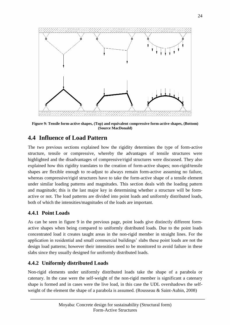
24
Moyaba: Concrete design for sustainability (Structural form)
Form-Active Structures
Figure 9: Tensile form-active shapes, (Top) and equivalent compressive form-active shapes, (Bottom)
(Source MacDonald)
4.4 Influence of Load Pattern
The two previous sections explained how the rigidity determines the type of form-active
structure, tensile or compressive, whereby the advantages of tensile structures were
highlighted and the disadvantages of compressive/rigid structures were discussed. They also
explained how this rigidity translates to the creation of form-active shapes; non-rigid/tensile
shapes are flexible enough to re-adjust to always remain form-active assuming no failure,
whereas compressive/rigid structures have to take the form-active shape of a tensile element
under similar loading patterns and magnitudes. This section deals with the loading pattern
and magnitude; this is the last major key in determining whether a structure will be form-
active or not. The load patterns are divided into point loads and uniformly distributed loads,
both of which the intensities/magnitudes of the loads are important.
4.4.1 Point Loads
As can be seen in figure 9 in the previous page, point loads give distinctly different form-
active shapes when being compared to uniformly distributed loads. Due to the point loads
concentrated load it creates taught areas in the non-rigid member in straight lines. For the
application in residential and small commercial buildings’ slabs these point loads are not the
design load patterns; however their intensities need to be monitored to avoid failure in these
slabs since they usually designed for uniformly distributed loads.
4.4.2 Uniformly distributed Loads
Non-rigid elements under uniformly distributed loads take the shape of a parabola or
catenary. In the case were the self-weight of the non-rigid member is significant a catenary
shape is formed and in cases were the live load, in this case the UDL overshadows the self-
weight of the element the shape of a parabola is assumed. (Rousseau & Saint-Aubin, 2008)
25
Moyaba: Concrete design for sustainability (Structural form)
Form-Active Structures
For application on slabs parabolas are thus the more accurate representation of the form-
active shape. This particular dependency of form-active shapes on the type of loading is
related to the bending moment diagrams that would result from these types of loading. In
relation to figure 9 again, it is evident that the form-active shape on the left is representative
of the bending moment diagram that would be plotted for such a loading arrangement,
consequently the loading magnitude as well. It follows logically that the middle form-active
shape is related to the bending moment diagram that would be plotted for the two point loads
with the different magnitudes, the same applies for the form-active shape on the right. Since
the latter is a shape resulting from a uniformly distributed load, the resulting bending moment
diagram follows the shape of a parabola, see appendix B for the equation of a bending
moment diagram resulting from a UDL. This supports the reasoning for taking a parabola as a
representation of a form-active shape in the design of form-active slabs under UDL’s.
The importance in the form-active shape being directly related to the loads bending moment
diagram will be discussed in the Analytical Methodology section whereby the design of the
form-active slabs will be discussed.
4.5 Degree of Form-Active Elements
According to how closely related the element shape is to the form-active shape, the element
can be categorised in one of the following three categories;
Non Form-Active Structures
These elements have no relationship with the form-active shape. This is characteristic of the
traditional solid slab and the discussed slabs in sections 2.2.1 -2.2.3. The slabs discussed in
sections 2.2.1 – 2.2.3 also take the overall shape of the solid slab. However, these slabs are
more efficient than the solid slab because they have improves section either in cross section
or longitudinal section. The improved section means the concrete that adds no structural
worth was remove, leaving the structure being lighter and thus more efficient.
Semi Form-Active Structures
These structures have overall shapes closely related to the true form-active shapes but do not
have the exact form-active shape. They are more efficient than elements with improved
sections because not only do they have excess concrete removed but also their form is
structurally active.
Form-active concrete slabs and other concrete structures are likely to fall under this category
simply because they cannot readjust their design shapes once the concrete has set. This is a
downside since dynamic live loading is inevitable, therefore in the design of these structures
for UDL’s, point loads should be considered so as to allow for the behaviour of the structure
under the possible loading it was not designed for.
Fully Form-Active Structures/Form-Active Structures
These structures maintain the true form-active shape of that particular load pattern and
magnitude. These are typically non-rigid elements. Some historical structures have certain
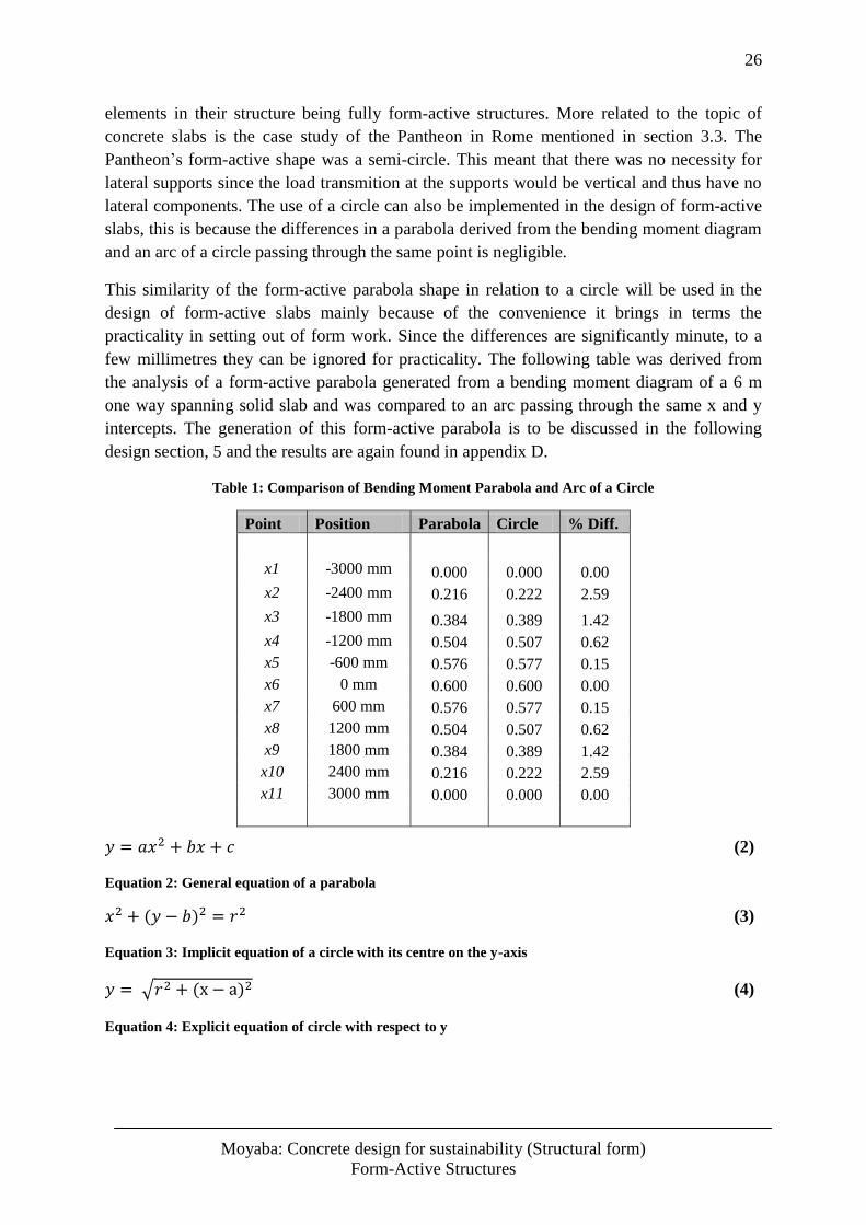
26
Moyaba: Concrete design for sustainability (Structural form)
Form-Active Structures
elements in their structure being fully form-active structures. More related to the topic of
concrete slabs is the case study of the Pantheon in Rome mentioned in section 3.3. The
Pantheon’s form-active shape was a semi-circle. This meant that there was no necessity for
lateral supports since the load transmition at the supports would be vertical and thus have no
lateral components. The use of a circle can also be implemented in the design of form-active
slabs, this is because the differences in a parabola derived from the bending moment diagram
and an arc of a circle passing through the same point is negligible.
This similarity of the form-active parabola shape in relation to a circle will be used in the
design of form-active slabs mainly because of the convenience it brings in terms the
practicality in setting out of form work. Since the differences are significantly minute, to a
few millimetres they can be ignored for practicality. The following table was derived from
the analysis of a form-active parabola generated from a bending moment diagram of a 6 m
one way spanning solid slab and was compared to an arc passing through the same x and y
intercepts. The generation of this form-active parabola is to be discussed in the following
design section, 5 and the results are again found in appendix D.
Table 1: Comparison of Bending Moment Parabola and Arc of a Circle
Point Position Parabola Circle % Diff.
x1 -3000 mm 0.000 0.000 0.00
x2 -2400 mm 0.216 0.222 2.59
x3 -1800 mm 0.384 0.389 1.42
x4 -1200 mm 0.504 0.507 0.62
x5 -600 mm 0.576 0.577 0.15
x6 0 mm 0.600 0.600 0.00
x7 600 mm 0.576 0.577 0.15
x8 1200 mm 0.504 0.507 0.62
x9 1800 mm 0.384 0.389 1.42
x10 2400 mm 0.216 0.222 2.59
x11 3000 mm 0.000 0.000 0.00
(2)
Equation 2: General equation of a parabola
(3)
Equation 3: Implicit equation of a circle with its centre on the y-axis
(4)
Equation 4: Explicit equation of circle with respect to y
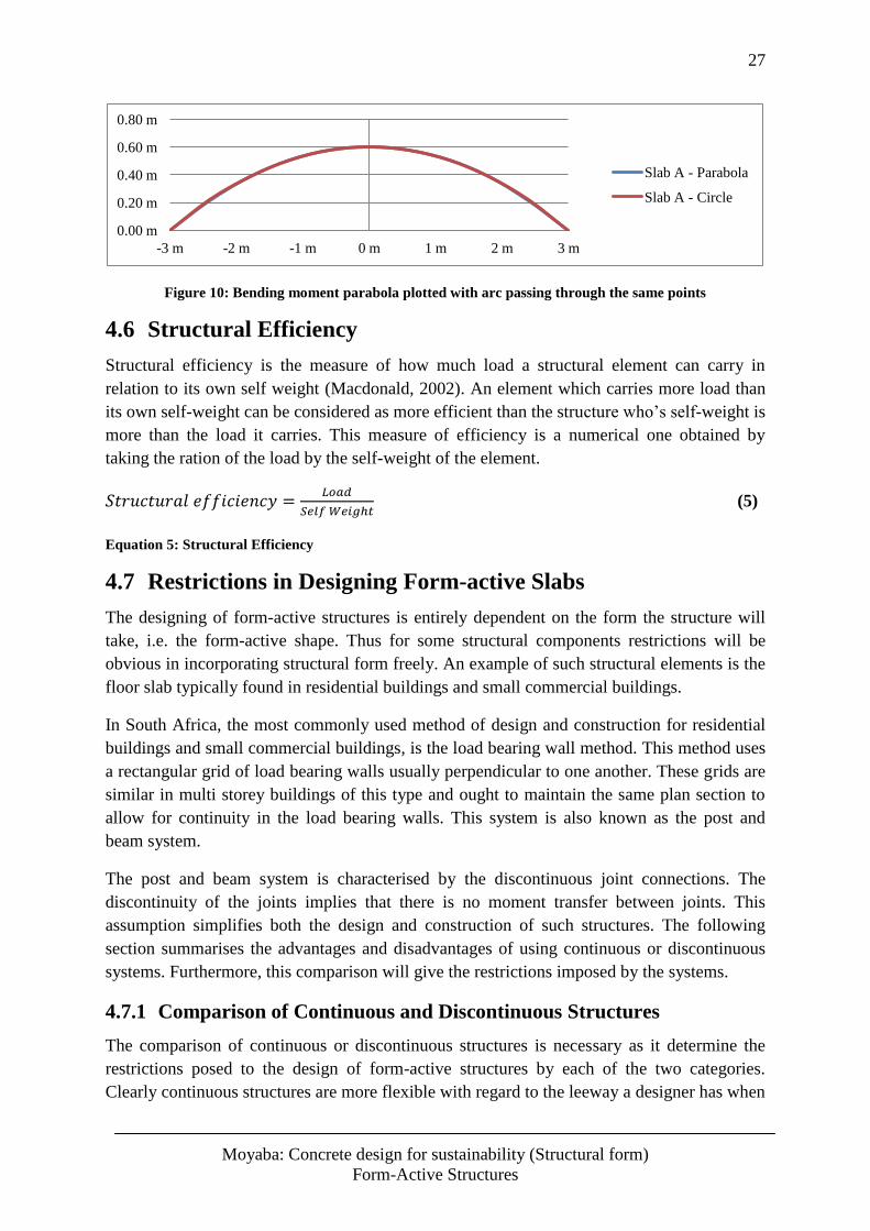
27
Moyaba: Concrete design for sustainability (Structural form)
Form-Active Structures
Figure 10: Bending moment parabola plotted with arc passing through the same points
4.6 Structural Efficiency
Structural efficiency is the measure of how much load a structural element can carry in
relation to its own self weight (Macdonald, 2002). An element which carries more load than
its own self-weight can be considered as more efficient than the structure who’s self-weight is
more than the load it carries. This measure of efficiency is a numerical one obtained by
taking the ration of the load by the self-weight of the element.
(5)
Equation 5: Structural Efficiency
4.7 Restrictions in Designing Form-active Slabs
The designing of form-active structures is entirely dependent on the form the structure will
take, i.e. the form-active shape. Thus for some structural components restrictions will be
obvious in incorporating structural form freely. An example of such structural elements is the
floor slab typically found in residential buildings and small commercial buildings.
In South Africa, the most commonly used method of design and construction for residential
buildings and small commercial buildings, is the load bearing wall method. This method uses
a rectangular grid of load bearing walls usually perpendicular to one another. These grids are
similar in multi storey buildings of this type and ought to maintain the same plan section to
allow for continuity in the load bearing walls. This system is also known as the post and
beam system.
The post and beam system is characterised by the discontinuous joint connections. The
discontinuity of the joints implies that there is no moment transfer between joints. This
assumption simplifies both the design and construction of such structures. The following
section summarises the advantages and disadvantages of using continuous or discontinuous
systems. Furthermore, this comparison will give the restrictions imposed by the systems.
4.7.1 Comparison of Continuous and Discontinuous Structures
The comparison of continuous or discontinuous structures is necessary as it determine the
restrictions posed to the design of form-active structures by each of the two categories.
Clearly continuous structures are more flexible with regard to the leeway a designer has when
0.00 m
0.20 m
0.40 m
0.60 m
0.80 m
-3 m -2 m -1 m 0 m 1 m 2 m 3 m
Slab A - Parabola
Slab A - Circle
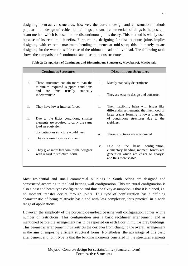
28
Moyaba: Concrete design for sustainability (Structural form)
Form-Active Structures
designing form-active structures, however, the current design and construction methods
popular in the design of residential buildings and small commercial buildings is the post and
beam method which is based on the discontinuous joints theory. This method is widely used
because of its economic benefits. Furthermore, designing for discontinuous joints implies
designing with extreme maximum bending moments at mid-span; this ultimately means
designing for the worst possible case of the ultimate dead and live load. The following table
shows the comparison of continuous and discontinuous structures.
Table 2: Comparison of Continuous and Discontinuous Structures, Moyaba, ref. MacDonald
Continuous Structures Discontinuous Structures
i. These structures contain more than the
minimum required support conditions
and are thus usually statically
indeterminate
ii. They have lower internal forces
iii. Due to the fixity conditions, smaller
elements are required to carry the same
load an equivalent
discontinuous structure would need
iv. They are usually more efficient
v. They give more freedom to the designer
with regard to structural form
i. Mostly statically determinate
ii. They are easy to design and construct
iii. Their flexibility helps with issues like
differential settlements, the likelihood of
large cracks forming is lower than that
of continuous structures due to the
rigidness
iv. These structures are economical
v. Due to the basic configuration,
elementary bending moment forces are
generated which are easier to analyse
and thus more viable
Most residential and small commercial buildings in South Africa are designed and
constructed according to the load bearing wall configuration. This structural configuration is
also a post and beam type configuration and thus the fixity assumption is that it is pinned, i.e.
no moment transfer occurs through joints. This type of configuration has a defining
characteristic of being relatively basic and with less complexity, thus practical in a wide
range of applications.
However, the simplicity of the post-and-beam/load bearing wall configuration comes with a
number of restrictions. This configuration uses a basic rectilinear arrangement, and as
mentioned before the arrangement has to be repeated on each floor in multi-storey buildings.
This geometric arrangement thus restricts the designer from changing the overall arrangement
in the aim of imposing efficient structural forms. Nonetheless, the advantage of this basic
arrangement and joint type is that the bending moments generated in the structural elements
29
Moyaba: Concrete design for sustainability (Structural form)
Form-Active Structures
are the elementary type which require less analysing time and thus easier to design for
(Macdonald, 2002).
In designing form-active structural elements for post-and-beam structures, the complete
structure will not be form-active. However, the elements that are essentially the structures
building blocks are designed to be form-active.
4.8 Closure
Having assessed the design requirements of form-active structures alongside the properties of
concrete as discussed in the earlier chapters a few reflections can be made;
Due to the rigidity of concrete, the concrete needs to mimic a mirrored shape of a
tensile structure under the same loading pattern and magnitude. From the literature
reviewed and analysis carried out as shown in appendix D, this shape is equivalent to
the resulting bending moment diagram under the particular load.
The design of form-active slabs for residential and small commercial buildings can
only go to the extent of being semi form-active. This is mostly because of
serviceability restrictions, i.e. the purpose of the slabs and partially due to the fact that
concrete is a rigid material during its lifetime and thus cannot readily re-adjust its
shape to accommodate changing load patterns and magnitudes.
Unlike the shape taken up by a cable under its own weight, i.e. catenary, the bending
moment diagram takes the form of a parabola. However, when compared with an arc
of a circle passing through the same points, the parabola has little difference to the
arc. Therefore the arc of a circle can be used to estimate this bending moment diagram
parabola when designing form-active slabs.
In order to keep the design concise and practical, the chosen types of structures for
these slabs were discontinuous structures, i.e. post-and-beam structures. This is also
due to the fact that these structures are the commonly designed structures in South
Africa for residential and small commercial buildings. For the same reason, the slab
design is to focus on one-way spanning slabs.
These key points are to serve as the boundary conditions in the design of the form-active
slabs in the following section, the form-active slabs are to be contrasted with equivalent one
way spanning slabs of the same span to allow for a thorough comparison of the two types of
slabs.
30
Moyaba: Concrete design for sustainability (Structural form)
Analytical Methodology
5 Analytical Methodology
5.1 Introduction
This section is concerned with the application of the concepts discussed in section 4 to design
form-active slabs in order to compare them with the equivalent traditional solid slabs. The
solid slab, is to be enhanced according to steel and concrete optimisation, i.e. material and
cost optimisation. The improvement of the traditional solid slab is done in order to compare
the form-active slab with a practical and rigorously designed slab. Both the design of the
traditional as well as the form-active slab are to be done as components for post-and-beam
structures, thus they are to be designed as discontinuous with pin supports at both ends. As
mentioned in the previous section, the choice of the post-and-beam structure as a design
boundary was driven by the widespread use of this structural arrangement both in design and
construction in South Africa.
The comparison of these slabs will be with regard to their structural efficiencies,
encompassing both the concrete and steel utilised for the two types of slabs. This section’s
aim is thus to provide quantitative results to be used to support the predicted properties of
form-active slabs.
5.2 Choice of Load Analysis Method
The chosen load analysis method assumes concrete in the elastic zones. This is because
concrete does not yield, it crushes. The chosen slab strip to be designed, both as a solid slab
according to SANS 0100-1 and form-active slab design techniques was a 1m strip of a one
way spanning slab. Using the 1m strip simplifies the application of this strip to the entire area
of the slab since it is a unit. The strip was chosen to be one way spanning. This was to avoid
analysis methods such as load apportioning in two way spanning slabs as that may divert the
purpose mentioned earlier of finding out what difference it makes to design a slab as form-
active rather than a solid flat slab. Thus, simplicity in load analysis was needed for a clearer
observation on what applying different form has.
One way spanning slabs simply supported on either ends give an elementary loading
arrangement which results in simple bending moment diagrams of which if correctly
designed they can be easily applied on site. Choosing complex loading arrangements and
support conditions such as continuous supports will increase the complexity of the resulting
bending moment diagram, and as the relationship of the bending moment diagram with the
form-active shape was discussed in the previous section, the form-active shape will also have
to be a complex one.
While it is possible to design complex form-active structural elements from complex bending
moment diagrams, it would not be practical since the constructed structure has to take that
shape to a reasonable precision. For this reason, a simple loading arrangement was chosen
and its bending moment diagram was used for both the traditional solid slab design and the
form-active slab design, See Appendix B.
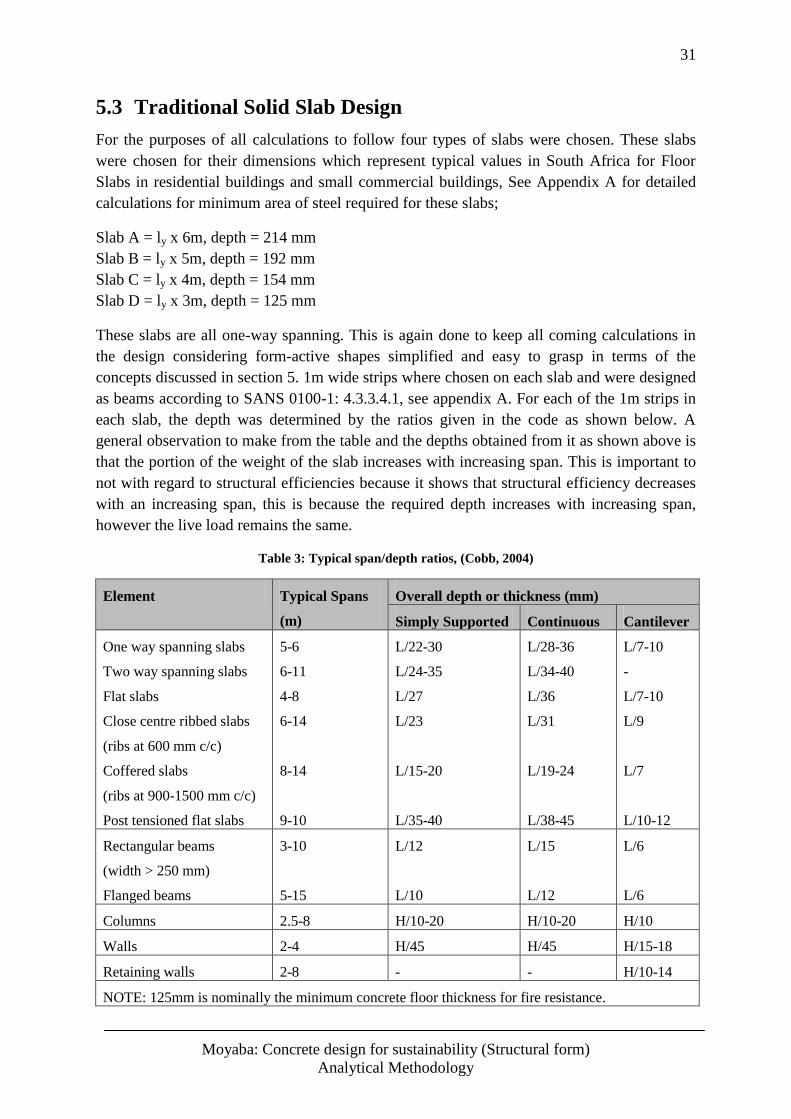
31
Moyaba: Concrete design for sustainability (Structural form)
Analytical Methodology
5.3 Traditional Solid Slab Design
For the purposes of all calculations to follow four types of slabs were chosen. These slabs
were chosen for their dimensions which represent typical values in South Africa for Floor
Slabs in residential buildings and small commercial buildings, See Appendix A for detailed
calculations for minimum area of steel required for these slabs;
Slab A = ly x 6m, depth = 214 mm
Slab B = ly x 5m, depth = 192 mm
Slab C = ly x 4m, depth = 154 mm
Slab D = ly x 3m, depth = 125 mm
These slabs are all one-way spanning. This is again done to keep all coming calculations in
the design considering form-active shapes simplified and easy to grasp in terms of the
concepts discussed in section 5. 1m wide strips where chosen on each slab and were designed
as beams according to SANS 0100-1: 4.3.3.4.1, see appendix A. For each of the 1m strips in
each slab, the depth was determined by the ratios given in the code as shown below. A
general observation to make from the table and the depths obtained from it as shown above is
that the portion of the weight of the slab increases with increasing span. This is important to
not with regard to structural efficiencies because it shows that structural efficiency decreases
with an increasing span, this is because the required depth increases with increasing span,
however the live load remains the same.
Table 3: Typical span/depth ratios, (Cobb, 2004)
Element Typical Spans
(m)
Overall depth or thickness (mm)
Simply Supported Continuous Cantilever
One way spanning slabs
Two way spanning slabs
Flat slabs
Close centre ribbed slabs
(ribs at 600 mm c/c)
Coffered slabs
(ribs at 900-1500 mm c/c)
Post tensioned flat slabs
5-6
6-11
4-8
6-14
8-14
9-10
L/22-30
L/24-35
L/27
L/23
L/15-20
L/35-40
L/28-36
L/34-40
L/36
L/31
L/19-24
L/38-45
L/7-10
-
L/7-10
L/9
L/7
L/10-12
Rectangular beams
(width > 250 mm)
Flanged beams
3-10
5-15
L/12
L/10
L/15
L/12
L/6
L/6
Columns 2.5-8 H/10-20 H/10-20 H/10
Walls 2-4 H/45 H/45 H/15-18
Retaining walls 2-8 - - H/10-14
NOTE: 125mm is nominally the minimum concrete floor thickness for fire resistance.
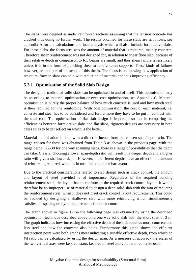
32
Moyaba: Concrete design for sustainability (Structural form)
Analytical Methodology
The slabs were deigned as under reinforced sections assuming that the tension concrete has
cracked thus doing no further work. The results obtained for these slabs are as follows, see
appendix A for the calculations and load analysis which will also include form-active slabs.
For these slabs, the focus area was the amount of material that is required, mainly concrete.
Therefore shear reinforcement was not designed for, in relation to shear floor slab, because of
their relative depth in comparison to RC beams are small, and thus shear failure is less likely
unless it is in the form of punching shear around column supports. These kinds of failures
however, are not part of the scope of this thesis. The focus is on showing how application of
structural form in slabs can help with reduction of material and thus improving efficiency.
5.3.1 Optimisation of the Solid Slab Design
The design of traditional solid slabs can be optimised in and of itself. This optimisation may
be according to material optimisation or even cost optimisation, see Appendix C. Material
optimisation is purely the proper balance of how much concrete is used and how much steel
is then required for the reinforcing. With cost optimisation, the cost of each material, i.e.
concrete and steel has to be considered and furthermore they have to be put in contrast with
the total cost. The optimisation of flat slab design is important so that in comparing the
efficiencies between form-active slabs and flat slabs, rigorous designs are necessary in both
cases so as to better reflect on which is the better.
Material optimisation is done with a direct influence from the chosen span/depth ratio. The
range chosen for these was obtained from Table 3 as shown in the previous page, with the
range being l/22-30 for one way spanning slabs, there is a range of possibilities that the depth
can take. Clearly, choosing a lower span/depth ratio will result in a deeper depth and a higher
ratio will give a shallower depth. However, the different depths have an effect in the amount
of reinforcing required, which is in turn linked to the rebar layout.
Due to the practical considerations related to slab design such as crack control, the amount
and layout of steel provided is of importance. Regardless of the required bending
reinforcement steel, the layout has to conform to the required crack control layout. It would
therefore be an improper use of material to design a deep solid slab with the aim of reducing
the reinforcement steel, when it does not meet crack control layout requirements. This could
be avoided by designing a shallower slab with more reinforcing which simultaneously
satisfies the spacing or layout requirements for crack control.
The graph shown in figure 12 on the following page was obtained by using the described
optimisation technique described above on a one way solid slab with the short span of 3 m.
The graph indicates how increasing the effective depth of the slab requires more concrete and
less steel and how the converse also holds. Furthermore this graph shows the efficient
intersection point were both graphs meet indicating a suitable effective depth, from which an
l/d ratio can be calculated by using the design span. As a measure of accuracy the scales of
the two vertical axes were kept constant, i.e. area of steel and volume of concrete used.
33
Moyaba: Concrete design for sustainability (Structural form)
Analytical Methodology
Ensuring the accuracy of the intersection point of these two graphs was done by aligning the
primary axis with the secondary axis. The alignment was done by keeping the ratios of the
maximum y value to the minimum y value for both the primary and secondary axis equal, i.e.
(6)
Equation 6: Ratio of maximum Y value to minimum Y value for axes alignment
In order to align the tick marks the increments on the secondary axis were calculated by a
similar factor to that of the primary axis. These alignments avoided distorting the theoretical
intersection of the two graphs because they are in different ranges of value, i.e. area and
volume. Hence, after ensuring the accurate intersection point the efficient effective depth was
extrapolated on the horizontal axis and this point represents the most efficient combination of
the two materials.
Figure 11: Material optimisation graph of steel vs. concrete, Moyaba
Cost optimisation was also considered as it has a major weighing in industry. In all material
combinations concrete is counts for the most volume, however, since steel is more expensive
than concrete, the cost efficiency calculation is necessary in determining the most optimum
combination.
Designing for a deeper slab reduces the bending reinforcing requirement; this implies that as
the concrete’s total cost increases as the steels total cost decreases and vice-versa when
designing for a shallow slab. Nonetheless a balance needs to be determined because the true
determining factors are how sensitive the total cost is to the change in either the concrete cost
or steel cost. Figure 13 below shows the relationship the concrete cost, steel cost and total
cost have with increasing effective depth of the 3m one way spanning solid slab.
0.21
0.25
0.29
0.34
0.38
0.42
125
150
175
200
225
250
100 110 120 130 140
Vo
lum
e o
f C
on
crete
w U
sed
(m
3)
Are
a o
f S
teel
Use
d (
mm
2)
Effective Depth (mm)
Steel Used
Concrete Used
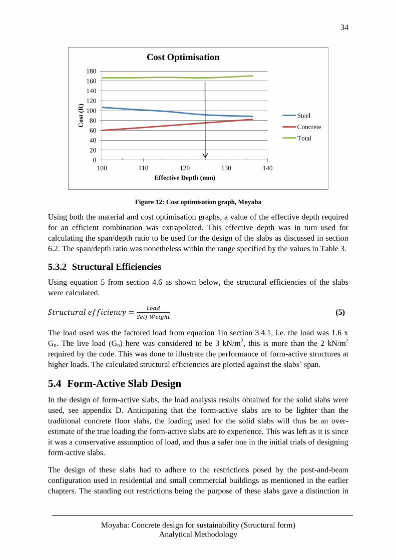
34
Moyaba: Concrete design for sustainability (Structural form)
Analytical Methodology
Figure 12: Cost optimisation graph, Moyaba
Using both the material and cost optimisation graphs, a value of the effective depth required
for an efficient combination was extrapolated. This effective depth was in turn used for
calculating the span/depth ratio to be used for the design of the slabs as discussed in section
6.2. The span/depth ratio was nonetheless within the range specified by the values in Table 3.
5.3.2 Structural Efficiencies
Using equation 5 from section 4.6 as shown below, the structural efficiencies of the slabs
were calculated.
(5)
The load used was the factored load from equation 1in section 3.4.1, i.e. the load was 1.6 x
Gn. The live load (Gn) here was considered to be 3 kN/m2, this is more than the 2 kN/m
2
required by the code. This was done to illustrate the performance of form-active structures at
higher loads. The calculated structural efficiencies are plotted against the slabs’ span.
5.4 Form-Active Slab Design
In the design of form-active slabs, the load analysis results obtained for the solid slabs were
used, see appendix D. Anticipating that the form-active slabs are to be lighter than the
traditional concrete floor slabs, the loading used for the solid slabs will thus be an over-
estimate of the true loading the form-active slabs are to experience. This was left as it is since
it was a conservative assumption of load, and thus a safer one in the initial trials of designing
form-active slabs.
The design of these slabs had to adhere to the restrictions posed by the post-and-beam
configuration used in residential and small commercial buildings as mentioned in the earlier
chapters. The standing out restrictions being the purpose of these slabs gave a distinction in
0
20
40
60
80
100
120
140
160
180
100 110 120 130 140
Co
st (
R)
Effective Depth (mm)
Cost Optimisation
Steel
Concrete
Total
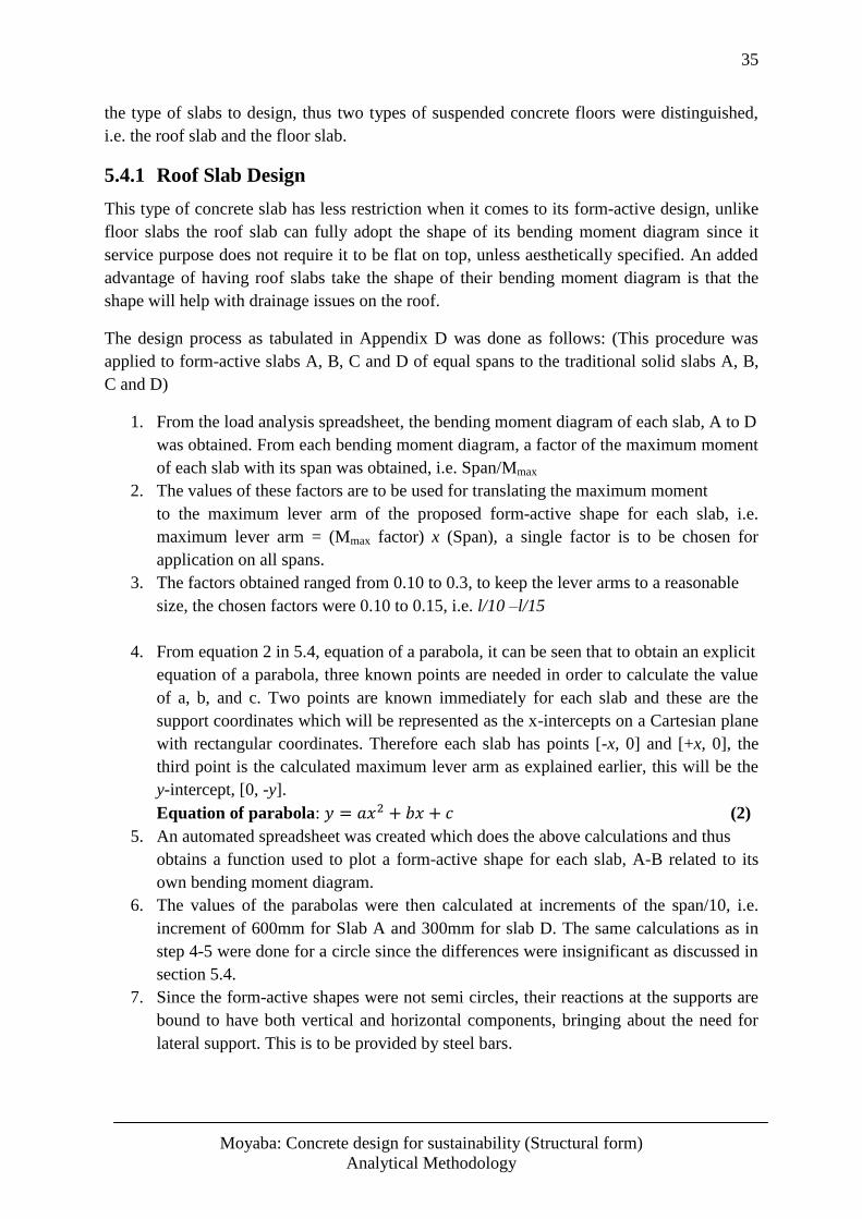
35
Moyaba: Concrete design for sustainability (Structural form)
Analytical Methodology
the type of slabs to design, thus two types of suspended concrete floors were distinguished,
i.e. the roof slab and the floor slab.
5.4.1 Roof Slab Design
This type of concrete slab has less restriction when it comes to its form-active design, unlike
floor slabs the roof slab can fully adopt the shape of its bending moment diagram since it
service purpose does not require it to be flat on top, unless aesthetically specified. An added
advantage of having roof slabs take the shape of their bending moment diagram is that the
shape will help with drainage issues on the roof.
The design process as tabulated in Appendix D was done as follows: (This procedure was
applied to form-active slabs A, B, C and D of equal spans to the traditional solid slabs A, B,
C and D)
1. From the load analysis spreadsheet, the bending moment diagram of each slab, A to D
was obtained. From each bending moment diagram, a factor of the maximum moment
of each slab with its span was obtained, i.e. Span/Mmax
2. The values of these factors are to be used for translating the maximum moment
to the maximum lever arm of the proposed form-active shape for each slab, i.e.
maximum lever arm = (Mmax factor) x (Span), a single factor is to be chosen for
application on all spans.
3. The factors obtained ranged from 0.10 to 0.3, to keep the lever arms to a reasonable
size, the chosen factors were 0.10 to 0.15, i.e. l/10 –l/15
4. From equation 2 in 5.4, equation of a parabola, it can be seen that to obtain an explicit
equation of a parabola, three known points are needed in order to calculate the value
of a, b, and c. Two points are known immediately for each slab and these are the
support coordinates which will be represented as the x-intercepts on a Cartesian plane
with rectangular coordinates. Therefore each slab has points [-x, 0] and [+x, 0], the
third point is the calculated maximum lever arm as explained earlier, this will be the
y-intercept, [0, -y].
Equation of parabola: (2)
5. An automated spreadsheet was created which does the above calculations and thus
obtains a function used to plot a form-active shape for each slab, A-B related to its
own bending moment diagram.
6. The values of the parabolas were then calculated at increments of the span/10, i.e.
increment of 600mm for Slab A and 300mm for slab D. The same calculations as in
step 4-5 were done for a circle since the differences were insignificant as discussed in
section 5.4.
7. Since the form-active shapes were not semi circles, their reactions at the supports are
bound to have both vertical and horizontal components, bringing about the need for
lateral support. This is to be provided by steel bars.
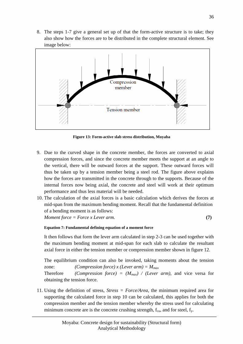
36
Moyaba: Concrete design for sustainability (Structural form)
Analytical Methodology
8. The steps 1-7 give a general set up of that the form-active structure is to take; they
also show how the forces are to be distributed in the complete structural element. See
image below:
Figure 13: Form-active slab stress distribution, Moyaba
9. Due to the curved shape in the concrete member, the forces are converted to axial
compression forces, and since the concrete member meets the support at an angle to
the vertical, there will be outward forces at the support. These outward forces will
thus be taken up by a tension member being a steel rod. The figure above explains
how the forces are transmitted in the concrete through to the supports. Because of the
internal forces now being axial, the concrete and steel will work at their optimum
performance and thus less material will be needed.
10. The calculation of the axial forces is a basic calculation which derives the forces at
mid-span from the maximum bending moment. Recall that the fundamental definition
of a bending moment is as follows:
Moment force = Force x Lever arm. (7)
Equation 7: Fundamental defining equation of a moment force
It then follows that form the lever arm calculated in step 2-3 can be used together with
the maximum bending moment at mid-span for each slab to calculate the resultant
axial force in either the tension member or compression member shown in figure 12.
The equilibrium condition can also be invoked, taking moments about the tension
zone: (Compression force) x (Lever arm) = Mmax
Therefore (Compression force) = (Mmax) / (Lever arm), and vice versa for
obtaining the tension force.
11. Using the definition of stress, Stress = Force/Area, the minimum required area for
supporting the calculated force in step 10 can be calculated, this applies for both the
compression member and the tension member whereby the stress used for calculating
minimum concrete are is the concrete crushing strength, fcu, and for steel, fy.
37
Moyaba: Concrete design for sustainability (Structural form)
Analytical Methodology
12. The minimum area of steel required will be directly used to read of from the bar size
selection chart, this minimum area will have to be applied every 1m strip of the slab
due to the chosen 1m design strip. However, for the concrete the square root of the
area was used to obtain the concrete depth required.
5.4.2 Floor Slab Design
The design of suspended floor slabs has to adhere to the service limitations of having a flat
top. The design procedure will be similar to the one described above. To create a flat top, the
voids may be created towards the support. These voids are to be covered with screed, and
possibly mesh for the screed’s robustness. This is shown on figure 14 below.
Other methods may include the use of timber floors on the top side of the form-active slab.
These timber floors will be supported at the supports of the slab and at mid-span.
Figure 14: Form-active floor slab
5.4.3 Comparison of Form-active Shapes
The form-active shapes considered for the design of concrete slabs in this thesis were the
parabola and the catenary. The catenary as explained in section 5, occurs on a chain or a
tension member like a cable on a suspension bridge under the uniformly distributed load of
its own weight. This implies that a catenary will develop when its self-weight is significant.
For the application on floor slabs, a cable spanning the same distances as the chosen slabs
will have a negligible self-weight when compared to the ULS loads the slabs are to be
designed to carry. This analogy was encountered on a study of catenaries whereby a common
case study is the example of the cable on a suspension bridge, since the deck of the bridge
overshadows the self-weight of the catenary, the resulting from active shape becomes a
parabola. For this reason a parabola was chosen as the preferred form-active shape, this was
supported by the shape of the bending moment diagram of a simply supported 1m strip taking
a form of a parabola, see Appendix D.
The parabola was compared with an arc of a circle passing through the same three points, i.e.
the two supports on either end of the span and the position of the maximum lever arm.
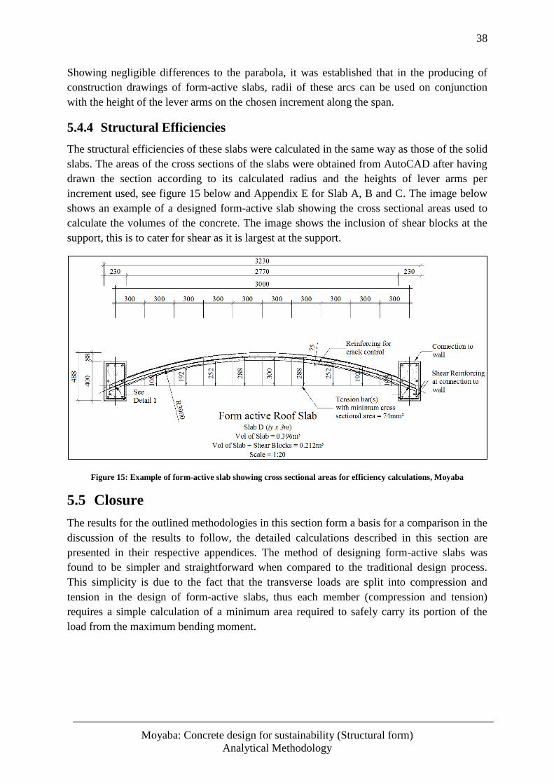
38
Moyaba: Concrete design for sustainability (Structural form)
Analytical Methodology
Showing negligible differences to the parabola, it was established that in the producing of
construction drawings of form-active slabs, radii of these arcs can be used on conjunction
with the height of the lever arms on the chosen increment along the span.
5.4.4 Structural Efficiencies
The structural efficiencies of these slabs were calculated in the same way as those of the solid
slabs. The areas of the cross sections of the slabs were obtained from AutoCAD after having
drawn the section according to its calculated radius and the heights of lever arms per
increment used, see figure 15 below and Appendix E for Slab A, B and C. The image below
shows an example of a designed form-active slab showing the cross sectional areas used to
calculate the volumes of the concrete. The image shows the inclusion of shear blocks at the
support, this is to cater for shear as it is largest at the support.
Figure 15: Example of form-active slab showing cross sectional areas for efficiency calculations, Moyaba
5.5 Closure
The results for the outlined methodologies in this section form a basis for a comparison in the
discussion of the results to follow, the detailed calculations described in this section are
presented in their respective appendices. The method of designing form-active slabs was
found to be simpler and straightforward when compared to the traditional design process.
This simplicity is due to the fact that the transverse loads are split into compression and
tension in the design of form-active slabs, thus each member (compression and tension)
requires a simple calculation of a minimum area required to safely carry its portion of the
load from the maximum bending moment.
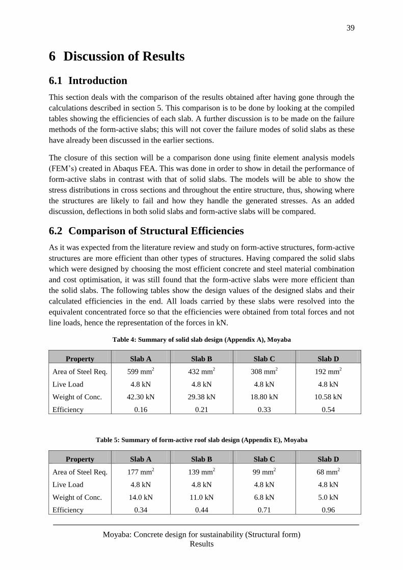
39
Moyaba: Concrete design for sustainability (Structural form)
Results
6 Discussion of Results
6.1 Introduction
This section deals with the comparison of the results obtained after having gone through the
calculations described in section 5. This comparison is to be done by looking at the compiled
tables showing the efficiencies of each slab. A further discussion is to be made on the failure
methods of the form-active slabs; this will not cover the failure modes of solid slabs as these
have already been discussed in the earlier sections.
The closure of this section will be a comparison done using finite element analysis models
(FEM’s) created in Abaqus FEA. This was done in order to show in detail the performance of
form-active slabs in contrast with that of solid slabs. The models will be able to show the
stress distributions in cross sections and throughout the entire structure, thus, showing where
the structures are likely to fail and how they handle the generated stresses. As an added
discussion, deflections in both solid slabs and form-active slabs will be compared.
6.2 Comparison of Structural Efficiencies
As it was expected from the literature review and study on form-active structures, form-active
structures are more efficient than other types of structures. Having compared the solid slabs
which were designed by choosing the most efficient concrete and steel material combination
and cost optimisation, it was still found that the form-active slabs were more efficient than
the solid slabs. The following tables show the design values of the designed slabs and their
calculated efficiencies in the end. All loads carried by these slabs were resolved into the
equivalent concentrated force so that the efficiencies were obtained from total forces and not
line loads, hence the representation of the forces in kN.
Table 4: Summary of solid slab design (Appendix A), Moyaba
Property Slab A Slab B Slab C Slab D
Area of Steel Req.
Live Load
Weight of Conc.
Efficiency
599 mm2
4.8 kN
42.30 kN
0.16
432 mm2
4.8 kN
29.38 kN
0.21
308 mm2
4.8 kN
18.80 kN
0.33
192 mm2
4.8 kN
10.58 kN
0.54
Table 5: Summary of form-active roof slab design (Appendix E), Moyaba
Property Slab A Slab B Slab C Slab D
Area of Steel Req.
Live Load
Weight of Conc.
Efficiency
177 mm2
4.8 kN
14.0 kN
0.34
139 mm2
4.8 kN
11.0 kN
0.44
99 mm2
4.8 kN
6.8 kN
0.71
68 mm2
4.8 kN
5.0 kN
0.96
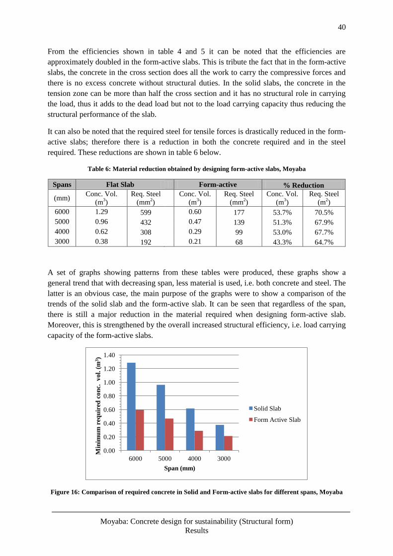
40
Moyaba: Concrete design for sustainability (Structural form)
Results
From the efficiencies shown in table 4 and 5 it can be noted that the efficiencies are
approximately doubled in the form-active slabs. This is tribute the fact that in the form-active
slabs, the concrete in the cross section does all the work to carry the compressive forces and
there is no excess concrete without structural duties. In the solid slabs, the concrete in the
tension zone can be more than half the cross section and it has no structural role in carrying
the load, thus it adds to the dead load but not to the load carrying capacity thus reducing the
structural performance of the slab.
It can also be noted that the required steel for tensile forces is drastically reduced in the form-
active slabs; therefore there is a reduction in both the concrete required and in the steel
required. These reductions are shown in table 6 below.
Table 6: Material reduction obtained by designing form-active slabs, Moyaba
Spans Flat Slab Form-active % Reduction
(mm) Conc. Vol.
(m3)
Req. Steel
(mm2)
Conc. Vol.
(m3)
Req. Steel
(mm2)
Conc. Vol.
(m3)
Req. Steel
(m2)
6000 1.29 599
0.60 177 53.7% 70.5%
5000 0.96 432
0.47 139 51.3% 67.9%
4000 0.62 308
0.29 99 53.0% 67.7%
3000 0.38 192
0.21 68 43.3% 64.7%
A set of graphs showing patterns from these tables were produced, these graphs show a
general trend that with decreasing span, less material is used, i.e. both concrete and steel. The
latter is an obvious case, the main purpose of the graphs were to show a comparison of the
trends of the solid slab and the form-active slab. It can be seen that regardless of the span,
there is still a major reduction in the material required when designing form-active slab.
Moreover, this is strengthened by the overall increased structural efficiency, i.e. load carrying
capacity of the form-active slabs.
Figure 16: Comparison of required concrete in Solid and Form-active slabs for different spans, Moyaba
0.00
0.20
0.40
0.60
0.80
1.00
1.20
1.40
6000 5000 4000 3000
Min
imu
m r
eq
uir
ed c
on
c.
vo
l. (
m3)
Span (mm)
Solid Slab
Form Active Slab
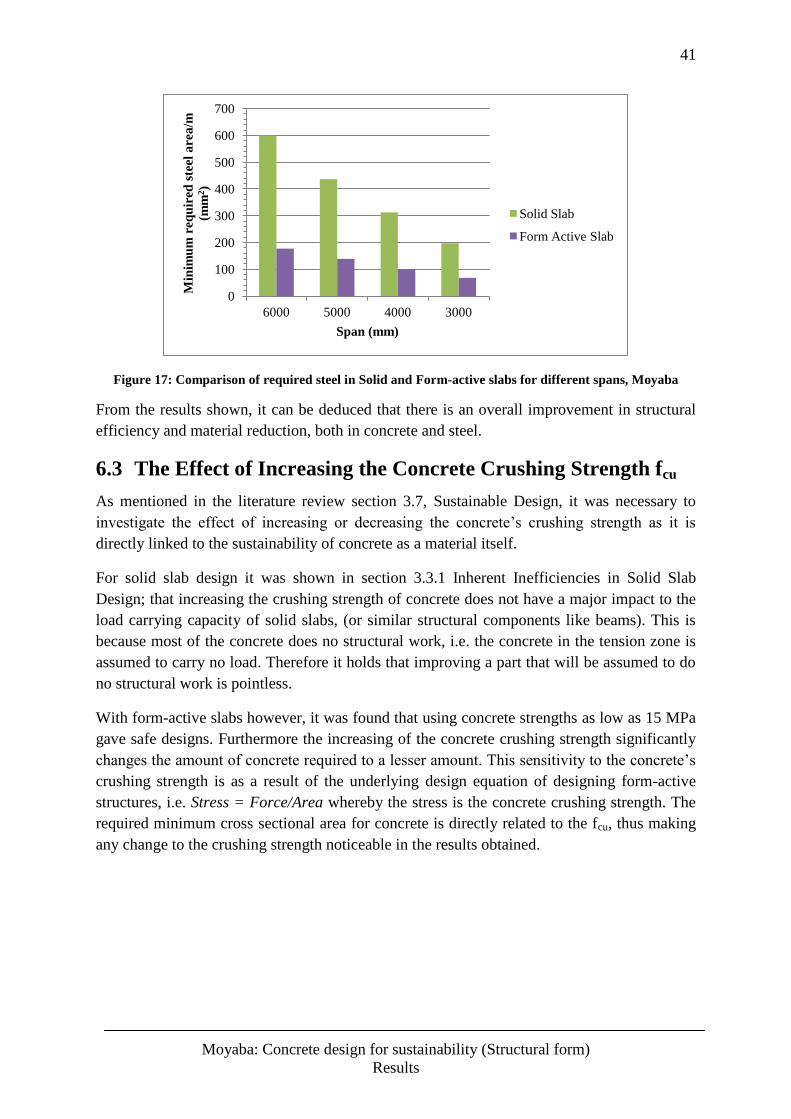
41
Moyaba: Concrete design for sustainability (Structural form)
Results
Figure 17: Comparison of required steel in Solid and Form-active slabs for different spans, Moyaba
From the results shown, it can be deduced that there is an overall improvement in structural
efficiency and material reduction, both in concrete and steel.
6.3 The Effect of Increasing the Concrete Crushing Strength fcu
As mentioned in the literature review section 3.7, Sustainable Design, it was necessary to
investigate the effect of increasing or decreasing the concrete’s crushing strength as it is
directly linked to the sustainability of concrete as a material itself.
For solid slab design it was shown in section 3.3.1 Inherent Inefficiencies in Solid Slab
Design; that increasing the crushing strength of concrete does not have a major impact to the
load carrying capacity of solid slabs, (or similar structural components like beams). This is
because most of the concrete does no structural work, i.e. the concrete in the tension zone is
assumed to carry no load. Therefore it holds that improving a part that will be assumed to do
no structural work is pointless.
With form-active slabs however, it was found that using concrete strengths as low as 15 MPa
gave safe designs. Furthermore the increasing of the concrete crushing strength significantly
changes the amount of concrete required to a lesser amount. This sensitivity to the concrete’s
crushing strength is as a result of the underlying design equation of designing form-active
structures, i.e. Stress = Force/Area whereby the stress is the concrete crushing strength. The
required minimum cross sectional area for concrete is directly related to the fcu, thus making
any change to the crushing strength noticeable in the results obtained.
0
100
200
300
400
500
600
700
6000 5000 4000 3000
Min
imu
m r
eq
uir
ed s
teel
are
a/m
(mm
2)
Span (mm)
Solid Slab
Form Active Slab
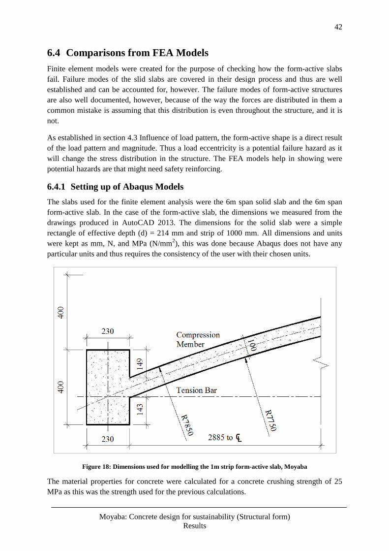
42
Moyaba: Concrete design for sustainability (Structural form)
Results
6.4 Comparisons from FEA Models
Finite element models were created for the purpose of checking how the form-active slabs
fail. Failure modes of the slid slabs are covered in their design process and thus are well
established and can be accounted for, however. The failure modes of form-active structures
are also well documented, however, because of the way the forces are distributed in them a
common mistake is assuming that this distribution is even throughout the structure, and it is
not.
As established in section 4.3 Influence of load pattern, the form-active shape is a direct result
of the load pattern and magnitude. Thus a load eccentricity is a potential failure hazard as it
will change the stress distribution in the structure. The FEA models help in showing were
potential hazards are that might need safety reinforcing.
6.4.1 Setting up of Abaqus Models
The slabs used for the finite element analysis were the 6m span solid slab and the 6m span
form-active slab. In the case of the form-active slab, the dimensions we measured from the
drawings produced in AutoCAD 2013. The dimensions for the solid slab were a simple
rectangle of effective depth (d) = 214 mm and strip of 1000 mm. All dimensions and units
were kept as mm, N, and MPa (N/mm2), this was done because Abaqus does not have any
particular units and thus requires the consistency of the user with their chosen units.
Figure 18: Dimensions used for modelling the 1m strip form-active slab, Moyaba
The material properties for concrete were calculated for a concrete crushing strength of 25
MPa as this was the strength used for the previous calculations.
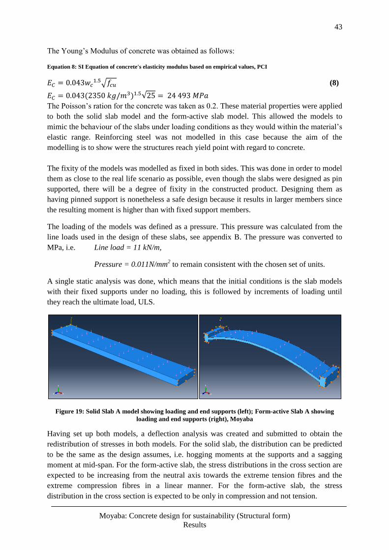
43
Moyaba: Concrete design for sustainability (Structural form)
Results
The Young’s Modulus of concrete was obtained as follows:
Equation 8: SI Equation of concrete's elasticity modulus based on empirical values, PCI
(8)
The Poisson’s ration for the concrete was taken as 0.2. These material properties were applied
to both the solid slab model and the form-active slab model. This allowed the models to
mimic the behaviour of the slabs under loading conditions as they would within the material’s
elastic range. Reinforcing steel was not modelled in this case because the aim of the
modelling is to show were the structures reach yield point with regard to concrete.
The fixity of the models was modelled as fixed in both sides. This was done in order to model
them as close to the real life scenario as possible, even though the slabs were designed as pin
supported, there will be a degree of fixity in the constructed product. Designing them as
having pinned support is nonetheless a safe design because it results in larger members since
the resulting moment is higher than with fixed support members.
The loading of the models was defined as a pressure. This pressure was calculated from the
line loads used in the design of these slabs, see appendix B. The pressure was converted to
MPa, i.e. Line load = 11 kN/m,
Pressure = 0.011N/mm2 to remain consistent with the chosen set of units.
A single static analysis was done, which means that the initial conditions is the slab models
with their fixed supports under no loading, this is followed by increments of loading until
they reach the ultimate load, ULS.
Figure 19: Solid Slab A model showing loading and end supports (left); Form-active Slab A showing
loading and end supports (right), Moyaba
Having set up both models, a deflection analysis was created and submitted to obtain the
redistribution of stresses in both models. For the solid slab, the distribution can be predicted
to be the same as the design assumes, i.e. hogging moments at the supports and a sagging
moment at mid-span. For the form-active slab, the stress distributions in the cross section are
expected to be increasing from the neutral axis towards the extreme tension fibres and the
extreme compression fibres in a linear manner. For the form-active slab, the stress
distribution in the cross section is expected to be only in compression and not tension.
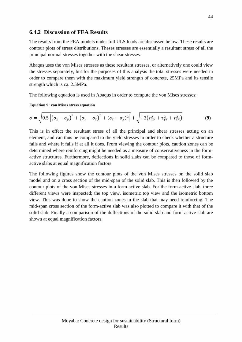
44
Moyaba: Concrete design for sustainability (Structural form)
Results
6.4.2 Discussion of FEA Results
The results from the FEA models under full ULS loads are discussed below. These results are
contour plots of stress distributions. Theses stresses are essentially a resultant stress of all the
principal normal stresses together with the shear stresses.
Abaqus uses the von Mises stresses as these resultant stresses, or alternatively one could view
the stresses separately, but for the purposes of this analysis the total stresses were needed in
order to compare them with the maximum yield strength of concrete, 25MPa and its tensile
strength which is ca. 2.5MPa.
The following equation is used in Abaqus in order to compute the von Mises stresses:
Equation 9: von Mises stress equation
(9)
This is in effect the resultant stress of all the principal and shear stresses acting on an
element, and can thus be compared to the yield stresses in order to check whether a structure
fails and where it fails if at all it does. From viewing the contour plots, caution zones can be
determined where reinforcing might be needed as a measure of conservativeness in the form-
active structures. Furthermore, deflections in solid slabs can be compared to those of form-
active slabs at equal magnification factors.
The following figures show the contour plots of the von Mises stresses on the solid slab
model and on a cross section of the mid-span of the solid slab. This is then followed by the
contour plots of the von Mises stresses in a form-active slab. For the form-active slab, three
different views were inspected; the top view, isometric top view and the isometric bottom
view. This was done to show the caution zones in the slab that may need reinforcing. The
mid-span cross section of the form-active slab was also plotted to compare it with that of the
solid slab. Finally a comparison of the deflections of the solid slab and form-active slab are
shown at equal magnification factors.
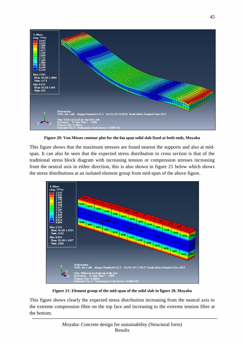
45
Moyaba: Concrete design for sustainability (Structural form)
Results
Figure 20: Von Misses contour plot for the 6m span solid slab fixed at both ends, Moyaba
This figure shows that the maximum stresses are found nearest the supports and also at mid-
span. It can also be seen that the expected stress distribution in cross section is that of the
traditional stress block diagram with increasing tension or compression stresses increasing
from the neutral axis in either direction, this is also shown in figure 21 below which shows
the stress distributions at an isolated element group from mid-span of the above figure.
Figure 21: Element group of the mid-span of the solid slab in figure 20, Moyaba
This figure shows clearly the expected stress distribution increasing from the neutral axis to
the extreme compression fibre on the top face and increasing to the extreme tension fibre at
the bottom.
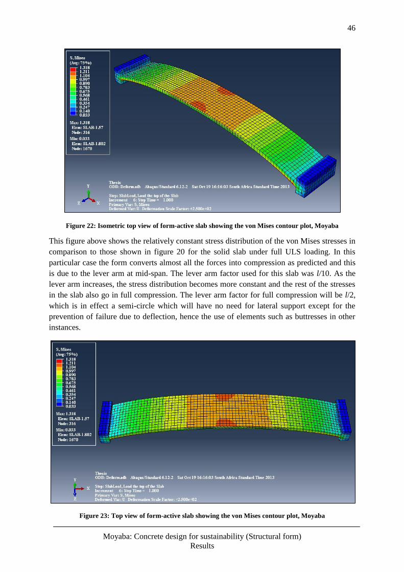
46
Moyaba: Concrete design for sustainability (Structural form)
Results
Figure 22: Isometric top view of form-active slab showing the von Mises contour plot, Moyaba
This figure above shows the relatively constant stress distribution of the von Mises stresses in
comparison to those shown in figure 20 for the solid slab under full ULS loading. In this
particular case the form converts almost all the forces into compression as predicted and this
is due to the lever arm at mid-span. The lever arm factor used for this slab was l/10. As the
lever arm increases, the stress distribution becomes more constant and the rest of the stresses
in the slab also go in full compression. The lever arm factor for full compression will be l/2,
which is in effect a semi-circle which will have no need for lateral support except for the
prevention of failure due to deflection, hence the use of elements such as buttresses in other
instances.
Figure 23: Top view of form-active slab showing the von Mises contour plot, Moyaba
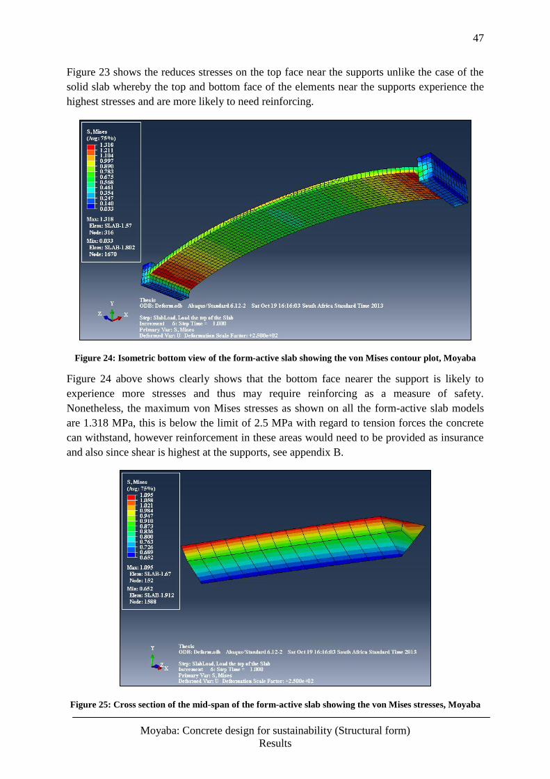
47
Moyaba: Concrete design for sustainability (Structural form)
Results
Figure 23 shows the reduces stresses on the top face near the supports unlike the case of the
solid slab whereby the top and bottom face of the elements near the supports experience the
highest stresses and are more likely to need reinforcing.
Figure 24: Isometric bottom view of the form-active slab showing the von Mises contour plot, Moyaba
Figure 24 above shows clearly shows that the bottom face nearer the support is likely to
experience more stresses and thus may require reinforcing as a measure of safety.
Nonetheless, the maximum von Mises stresses as shown on all the form-active slab models
are 1.318 MPa, this is below the limit of 2.5 MPa with regard to tension forces the concrete
can withstand, however reinforcement in these areas would need to be provided as insurance
and also since shear is highest at the supports, see appendix B.
Figure 25: Cross section of the mid-span of the form-active slab showing the von Mises stresses, Moyaba
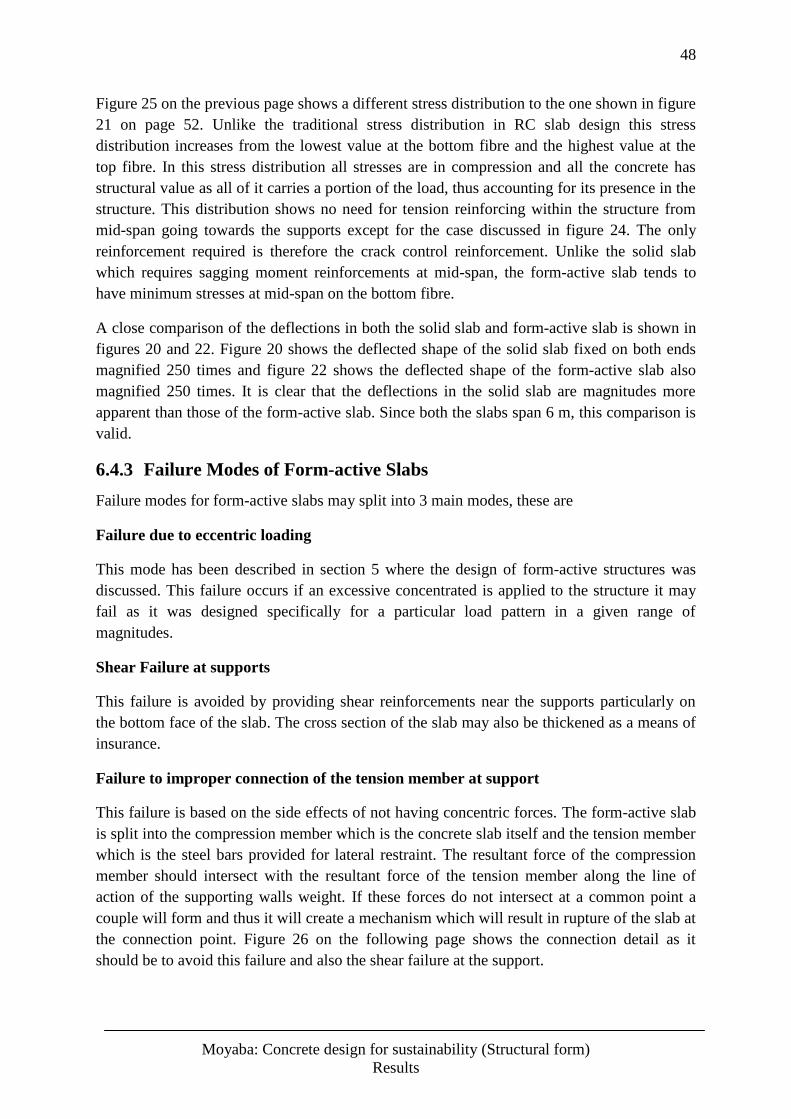
48
Moyaba: Concrete design for sustainability (Structural form)
Results
Figure 25 on the previous page shows a different stress distribution to the one shown in figure
21 on page 52. Unlike the traditional stress distribution in RC slab design this stress
distribution increases from the lowest value at the bottom fibre and the highest value at the
top fibre. In this stress distribution all stresses are in compression and all the concrete has
structural value as all of it carries a portion of the load, thus accounting for its presence in the
structure. This distribution shows no need for tension reinforcing within the structure from
mid-span going towards the supports except for the case discussed in figure 24. The only
reinforcement required is therefore the crack control reinforcement. Unlike the solid slab
which requires sagging moment reinforcements at mid-span, the form-active slab tends to
have minimum stresses at mid-span on the bottom fibre.
A close comparison of the deflections in both the solid slab and form-active slab is shown in
figures 20 and 22. Figure 20 shows the deflected shape of the solid slab fixed on both ends
magnified 250 times and figure 22 shows the deflected shape of the form-active slab also
magnified 250 times. It is clear that the deflections in the solid slab are magnitudes more
apparent than those of the form-active slab. Since both the slabs span 6 m, this comparison is
valid.
6.4.3 Failure Modes of Form-active Slabs
Failure modes for form-active slabs may split into 3 main modes, these are
Failure due to eccentric loading
This mode has been described in section 5 where the design of form-active structures was
discussed. This failure occurs if an excessive concentrated is applied to the structure it may
fail as it was designed specifically for a particular load pattern in a given range of
magnitudes.
Shear Failure at supports
This failure is avoided by providing shear reinforcements near the supports particularly on
the bottom face of the slab. The cross section of the slab may also be thickened as a means of
insurance.
Failure to improper connection of the tension member at support
This failure is based on the side effects of not having concentric forces. The form-active slab
is split into the compression member which is the concrete slab itself and the tension member
which is the steel bars provided for lateral restraint. The resultant force of the compression
member should intersect with the resultant force of the tension member along the line of
action of the supporting walls weight. If these forces do not intersect at a common point a
couple will form and thus it will create a mechanism which will result in rupture of the slab at
the connection point. Figure 26 on the following page shows the connection detail as it
should be to avoid this failure and also the shear failure at the support.
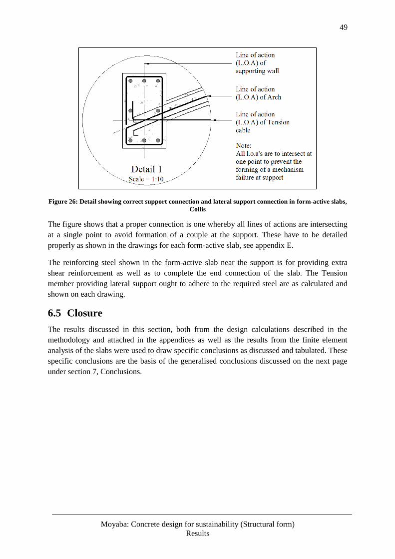
49
Moyaba: Concrete design for sustainability (Structural form)
Results
Figure 26: Detail showing correct support connection and lateral support connection in form-active slabs,
Collis
The figure shows that a proper connection is one whereby all lines of actions are intersecting
at a single point to avoid formation of a couple at the support. These have to be detailed
properly as shown in the drawings for each form-active slab, see appendix E.
The reinforcing steel shown in the form-active slab near the support is for providing extra
shear reinforcement as well as to complete the end connection of the slab. The Tension
member providing lateral support ought to adhere to the required steel are as calculated and
shown on each drawing.
6.5 Closure
The results discussed in this section, both from the design calculations described in the
methodology and attached in the appendices as well as the results from the finite element
analysis of the slabs were used to draw specific conclusions as discussed and tabulated. These
specific conclusions are the basis of the generalised conclusions discussed on the next page
under section 7, Conclusions.
50
Moyaba: Concrete design for sustainability (Structural form)
Conclusion
7 Conclusions
7.1 Specific Conclusions
The literature review produced in this thesis has shown form-active structures in history that
were soundly designed. Moreover, it has shown that the application of form-active structures
can be applied virtually in all types of structures in different ways while appreciating the
restrictions certain applications might pose.
A set of specific conclusions can be drawn from the discussion of results given in the
previous section, these conclusions are explicitly for the traditional solid slabs A, B, C and D
alongside the corresponding form-active slabs A, B, C and D;
In all the above mentioned slabs, there are significant reductions in the amount of
concrete and steel used when designing form-active slabs. The reduction in the
concrete used ranges from 43.3% reduction in the 3 m spanning slabs to 53.7% in the
6 m spanning slabs. The increase in the reduction of concrete used as span increases is
due to the fact that in larger spans the depth is nominally higher for the traditional
solid slabs, whereas the depth in the form active slabs only increases by a lesser
fraction as span increases.
With regard to the reinforcing steel used, the reduction is higher than the concrete
reduction, and this is because form active slabs are designed to eliminate the need of
reinforcing steel within the slab. Thus, the steel is only needed as a tension member to
resist the lateral forces generated and the only steel needed in the slab is mainly for
the connection to the support (also acting as shear resistance) and for crack control.
The steel reduction ranged from 64.7% reduction in the 3m spanning slabs to 70.5%
for the 6 m spanning slabs. These values are tabulated in table 6 under section 6.2.
Having optimised the solid slab design according to material and cost optimisation, it
was concluded that form active slabs are still much less material intensive and thus
more sustainable. In addition the form active slabs A to D, are consequently more
economic cost wise.
The efficiency of the traditional solid slabs was found to be approximately half that of the
efficiency of form-active slabs in all the slabs A, B, C and D. This is indicative of the
structural integrity of the form-active slabs themselves. For a more critical and thorough
analysis of the structural performance of form-active slabs in comparison to the traditional
solid slab, the solid slab A and form-active slab A were modelled and analysed in Abaqus
FEA. This was done in order to obtain an in-depth evaluation of the slabs’ performance under
simulated loading. The choice of the slabs A was due to their large spans, thus the evaluation
was done on the worst case scenario amongst the slabs, i.e. the maximum span of 6 m.
From analysing the results from the finite element analysis of the traditional solid slab A and
the form active slab A, the performance of the form active slab was found to be higher than
that of the traditional solid slab. This performance was with regard to load carrying capacity
51
Moyaba: Concrete design for sustainability (Structural form)
Conclusion
which is related to the calculated structural efficiencies and the performance was also with
regard to deflections.
The maximum von misses stresses generated in the solid slab were higher than the ones
generated in the form-active slab, this is suggestive that the traditional solid slab is more
likely to reach failure strength before the form-active slab reaches failure. The reason for the
differences in the stresses generated in the slabs, are due to the stress distributions. From a
close analysis of section cuts at the mid-span of both the traditional and form-active slabs, it
was shown that the form-active slab had a stress distribution of compressive stresses alone at
mid-span and this distribution remains virtually constant as we move towards either support.
This elimination of tensile stresses explains why not much reinforcing is needed in the form
active slabs. The traditional solid slab showed the expected stress distribution of increasing
tensile and compressive forces from the neutral axis, this is shown in figures 21 and 25 in
section 6.4.2.
The second performance criterion analysed was the resulting deflections. The deflections of
the traditional solid slab were within the limiting value of l/250 because the corresponding
span/depth ratios were used in designing them. However, in comparison to the deflections of
the form-active slabs under the same loading it was deduced that form active slabs have
relatively smaller deflections than the traditional solid slabs. This is because of the camber in
the form active shape generated by a uniformly distributed load, this is shown in figures 20
and 22 in comparison to the un-deflected ones in figure 19.
With regard to failure modes, the traditional solid slab’s failure modes are common modes of
failure covered in the traditional design process. The failure is due to cracking at positions of
maximum hogging and sagging moments, and excessive deflections. Shear failure for slabs is
less common due to their relative shallow depths in contrast to those of beams.
The failure modes for the form-active slabs are mostly due to the shear at the supports and
whether the connection of the tension member is done correctly or not. For this reason, shear
reinforcement is needed on the under-side of the slabs nearer the supports since this is a likely
place for tension forces to arise, see figure 24. Increasing the form-active slab thickness near
the supports can also help as insurance against shear failure, this is because the increased
thickness gives a larger area of concrete which can better resist the internal shear forces at
near the supports. The connection of the tension member should be done in such a way that
the resultant compression force in the slab coincides with the resultant force of the tension
member and that of the supporting wall at a common point. This ought to be done to avoid
the formation of a couple moment at the support which can lead to rapture of the slab at the
support.
From these findings it was determined that all the form-active slabs, A through to D were
superior to their traditional solid slab counterparts. This is with respect to structural efficiency
i.e. load carrying capacity, structural performance according to serviceability and in
deflections. The internal stress distributions in the form-active slabs are more favourable than
that of the traditional slabs and additionally the material used is significantly less.
52
Moyaba: Concrete design for sustainability (Structural form)
Conclusion
7.2 General Conclusions
Having investigated the overall design of form-active structures it was deduced that the
important things to note are the loading arrangement, the magnitude of the loading as well as
the type of structure that is being designed, i.e. a rigid or flexible structure; flexible structures
are naturally form-active while compressive structures require the imitation of a flexible
structure’s mirrored shape under similar loading conditions. The latter is the case with the
design of form-active slabs.
Upon the critical inspection of the traditional design process of the solid slab, it was found
that a major inherent inefficiency in the design is the fact that more than half the concrete in
the cross section is designed to carry no load, thus it adds to the dead load without carrying
any load at all. This gives these slabs a relatively lower structural efficiency. For this reason,
the design of form-active slabs is justified. Since the form-active slab is almost entirely in
compression, all the concrete has structural worth because they carry a portion of the load.
Furthermore, increasing the concrete crushing strength in these slabs significantly increases
the structural efficiency of the slabs.
Generally the performance of form-active slabs is much higher than that of the traditional
solid slab, deflections are minimised, and the amount of concrete is reduced by up to 60%
while the amount of steel required is reduced by up to 70%. Failure modes in these slabs can
be avoided by careful construction methods which avoid formations of couple moments at
supports, preventing excessive point loads and providing adequate shear resistance near the
supports. In constructing these slabs more often less material will be wasted, thus moving
towards sustainability in concrete structural design.
The application of one way spanning form-active slabs can be implemented in most
residential and small commercial buildings. This can lead to a cumulative saving of material
and cost while improving the structural integrity of these structures. Larger building
structures such as hospitals and malls can benefit from the application of one-way spanning
form-active slabs; these types of buildings are not explicitly rectilinear in design, they are
made up of rectangular grids with large hallways or corridors connecting the grids. These
corridors can benefit greatly if the slabs are designed as one way spanning form-active slabs
with wooden decks on the top face for example, see appendix E. The corridors are long and
therefore the concern lies with the cross-span which is the shorter span, making them
appropriate practical applications for form-active slabs. This type of application can also help
with regard to serviceability and maintenance of service ducts such as piping and air
conditioning since these ducts can be easily accessed from the top of the slabs.
A further related research field from which the slabs designed in this thesis are a special case,
is the research on shell structures. These are structures concerned with the structural form in
more than one dimension, thus instead of one way spans, the shape becomes a 3 dimensional
shell structure such as the roof dome of the Pantheon in Rome. These research fields are
important because they help with regards to designing efficiently and making engineering
materials perform at their optimum.
53
Moyaba: Concrete design for sustainability (Structural form)
References
8 References
Anastas, P., & Zimmerman, J. (2003). Design Through the 12 Principles Green Engineering.
Environmental Science & Technology, 95A-101A.
Brundtland, & World Commision on Enviroment and Development. (1987). Our Common Future.
Oxford University Press.
Călin, S., Gînţu, R., & Dascălu, G. (2009, February 3). Summary of Tests and Studies Done Abroad
on the Bubbledeck System. Retrieved July 04, 2013
CCAA, C. C. (2003, April). Guide to Residential Floors. Retrieved October 12, 2013, from Cement
Concrete & Aggregates Australia:
http://www.concrete.net.au/publications/pdf/Res%20Floors%20Web.pdf
CCAA, C. C. (2004, August). Concrete Basics: A guide to concrete practice 4th Ed. Retrieved July
19, 2013, from Cement Concrete & Aggregates Australia:
http://www.concrete.net.au/publications/pdf/concretebasics.pdf
Cobb, F. (2004). Structural Engineer's Pocket Book. Oxford: Elsevier Butterworth-Heinemann
publications.
CRSI, C. a. (1998). Reinforcing Steel in Slab-on-Grade. Illinois: Concrete and Reinforcing Steel
Institute.
Holedeck®. (2013). Holedeck®, The lean structure. Retrieved 07 19, 2013, from Holedeck®:
http://g.virbcdn.com/_f2/files/8b/FileItem-281116-HOLEDECKbrochure201303.pdf
Klane, D. (2007, April 29). Structural Engineers, Sustainability and Leed®. Retrieved July 16, 2013,
from http://content.asce.org/files/pdf/SEICongressStructuralengineersandLEED07Apr29.pdf
Lai, T. (2010, July 15). Structural behavior of Bubbledeck(R) slabs and their application to
lightweight bridge decks. Retrieved October 12, 2013, from dspace.mit.edu:
http://www.dspace.edu/bitstream/handle/1721.1/60774/693573130.pdf
Lárus H. Lárusson *, G. F. (2013). Prefabricated floor panels composed of fiber reinforced concrete.
Engineering Structures, 1-12.
Macdonald, A. J. (2002). Structure & Architecture - 2nd ed. Oxford: Architectural Press.
Rousseau, C., & Saint-Aubin, Y. (2008). Calculus of Variations. Retrieved October 11, 2013, from
math.berkeley.edu: http://math.berkeley.edu/~strain/170.S13/cov.pdf
RSC, R. S. (2008). The Concrete Conundrum. Retrieved July 16, 2013, from
www.chemistryworld.org: http://www.rsc.org/images/Construction_tcm18-114530.pdf
Salvadori, M. (1980). Why Buildings Stand Up. New York: W.W. Norton & Company.
Salvadori, M., & Heller, R. (1963). Structure in Architecture. New Jersey: Prentice-Hall.
Salvadori, M., & Levy, M. (1987). Why Buildings Fall Down. New York: W.W. Norton & Company.
54
Moyaba: Concrete design for sustainability (Structural form)
References
The South African Bureau of Standards. (2000, March 31). The Structural Use of Concrete: SABS
0100-1. Pretoria, Gauteng Province, South Africa.
Wilby, C. B. (1977). Concrete for Structural Engineers. London: Boston Newness-Butterworths.
55
Moyaba: Concrete design for sustainability (Structural form)
Appendices
Appendices
Appendix A - Solid Slab Design Calculations 56
Appendix B - Load Analysis 61
Appendix C - Optimisation of Solid Slabs, Slab A and Slab D 65
Appendix D - Form-Active Slab Design 68
Appendix E - Drawings 72
56
Moyaba: Concrete design for sustainability (Structural form)
Appendix A
Appendix A - Solid Slab Design Calculations
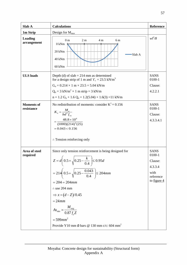
57
Moyaba: Concrete design for sustainability (Structural form)
Appendix A
Slab A Calculations Reference
1m Strip Design for Mmax
Loading
arrangement
wl2/8
ULS loads Depth (d) of slab = 214 mm as determined
for a design strip of 1 m and ϒc = 23.5 kN/m3
Gn = 0.214 × 1 m × 23.5 = 5.04 kN/m
Qn = 3 kN/m2 × 1 m strip = 3 kN/m
n = 1.2 Gn + 1.6 Qn = 1.2(5.04) + 1.6(3) =11 kN/m
SANS
0100-1
Clause:
4.2.2.1
Moments of
resistance
No redistribution of moments: consider K1 = 0.156
Kn Mu
bd2 fcu
48.8 106
(1000)(214)2(25)
0.043 0.156
∴ Tension reinforcing only
SANS
0100-1
Clause:
4.3.3.4.1
Area of steel
required
Since only tension reinforcement is being designed for
mm
mm
dk
dZ
204204
2044.0
043.025.05.0214
95.04.0
25.05.0
∴ use 204 mm
x d Z /0.45
24mm
Asmin Msag
0.87 fyZ
599mm2
Provide Y10 mm ∅ bars @ 130 mm c/c: 604 mm2
SANS
0100-1
Clause:
4.3.3.4
with
reference
to figure 4
0 kNm
20 kNm
40 kNm
60 kNm
0 m 2 m 4 m 6 m
Slab A
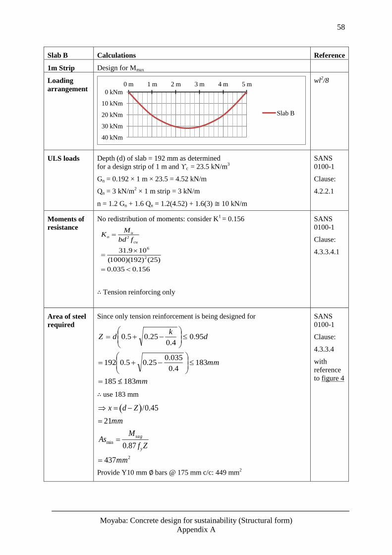
58
Moyaba: Concrete design for sustainability (Structural form)
Appendix A
Slab B Calculations Reference
1m Strip Design for Mmax
Loading
arrangement
wl2/8
ULS loads Depth (d) of slab = 192 mm as determined
for a design strip of 1 m and ϒc = 23.5 kN/m3
Gn = 0.192 × 1 m × 23.5 = 4.52 kN/m
Qn = 3 kN/m2 × 1 m strip = 3 kN/m
n = 1.2 Gn + 1.6 Qn = 1.2(4.52) + 1.6(3) ≅ 10 kN/m
SANS
0100-1
Clause:
4.2.2.1
Moments of
resistance
No redistribution of moments: consider K1 = 0.156
Kn Mu
bd2 fcu
31.9 106
(1000)(192)2(25)
0.035 0.156
∴ Tension reinforcing only
SANS
0100-1
Clause:
4.3.3.4.1
Area of steel
required
Since only tension reinforcement is being designed for
mm
mm
dk
dZ
183185
1834.0
035.025.05.0192
95.04.0
25.05.0
∴ use 183 mm
x d Z /0.45
21mm
Asmin Msag
0.87 fyZ
437mm2
Provide Y10 mm ∅ bars @ 175 mm c/c: 449 mm2
SANS
0100-1
Clause:
4.3.3.4
with
reference
to figure 4
0 kNm
10 kNm
20 kNm
30 kNm
40 kNm
0 m 1 m 2 m 3 m 4 m 5 m
Slab B
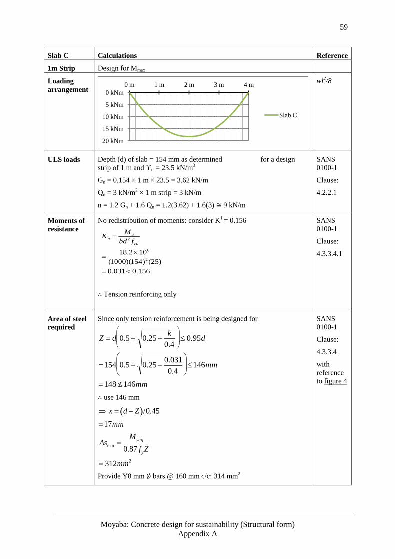
59
Moyaba: Concrete design for sustainability (Structural form)
Appendix A
Slab C Calculations Reference
1m Strip Design for Mmax
Loading
arrangement
wl2/8
ULS loads Depth (d) of slab = 154 mm as determined for a design
strip of 1 m and ϒc = 23.5 kN/m3
Gn = 0.154 × 1 m × 23.5 = 3.62 kN/m
Qn = 3 kN/m2 × 1 m strip = 3 kN/m
n = 1.2 Gn + 1.6 Qn = 1.2(3.62) + 1.6(3) ≅ 9 kN/m
SANS
0100-1
Clause:
4.2.2.1
Moments of
resistance
No redistribution of moments: consider K1 = 0.156
Kn Mu
bd2 fcu
18.2 106
(1000)(154)2(25)
0.031 0.156
∴ Tension reinforcing only
SANS
0100-1
Clause:
4.3.3.4.1
Area of steel
required
Since only tension reinforcement is being designed for
Z d 0.5 0.25k
0.4
0.95d
154 0.5 0.250.031
0.4
146mm
148 146mm
∴ use 146 mm
x d Z /0.45
17mm
Asmin Msag
0.87 fyZ
312mm2
Provide Y8 mm ∅ bars @ 160 mm c/c: 314 mm2
SANS
0100-1
Clause:
4.3.3.4
with
reference
to figure 4
0 kNm
5 kNm
10 kNm
15 kNm
20 kNm
0 m 1 m 2 m 3 m 4 m
Slab C
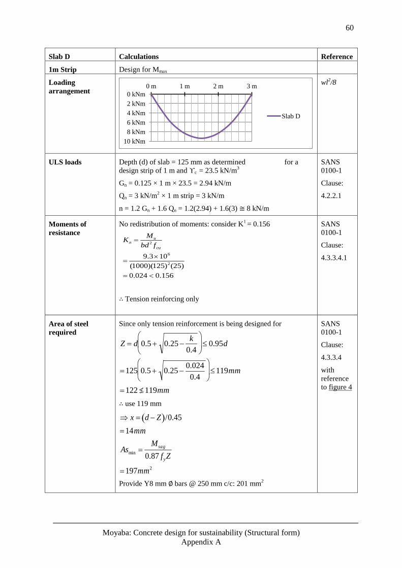
60
Moyaba: Concrete design for sustainability (Structural form)
Appendix A
Slab D Calculations Reference
1m Strip Design for Mmax
Loading
arrangement
wl2/8
ULS loads Depth (d) of slab = 125 mm as determined for a
design strip of 1 m and ϒc = 23.5 kN/m3
Gn = 0.125 × 1 m × 23.5 = 2.94 kN/m
Qn = 3 kN/m2 × 1 m strip = 3 kN/m
n = 1.2 Gn + 1.6 Qn = 1.2(2.94) + 1.6(3) ≅ 8 kN/m
SANS
0100-1
Clause:
4.2.2.1
Moments of
resistance
No redistribution of moments: consider K1 = 0.156
Kn Mu
bd2 fcu
9.3106
(1000)(125)2(25)
0.024 0.156
∴ Tension reinforcing only
SANS
0100-1
Clause:
4.3.3.4.1
Area of steel
required
Since only tension reinforcement is being designed for
Z d 0.5 0.25k
0.4
0.95d
125 0.5 0.250.024
0.4
119mm
122 119mm
∴ use 119 mm
x d Z /0.45
14mm
Asmin Msag
0.87 fyZ
197mm2
Provide Y8 mm ∅ bars @ 250 mm c/c: 201 mm2
SANS
0100-1
Clause:
4.3.3.4
with
reference
to figure 4
0 kNm
2 kNm
4 kNm
6 kNm
8 kNm
10 kNm
0 m 1 m 2 m 3 m
Slab D
61
Moyaba: Concrete design for sustainability (Structural form)
Appendix B
Appendix B - Load Analysis
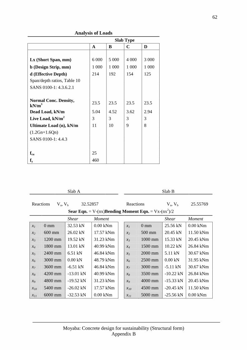
62
Moyaba: Concrete design for sustainability (Structural form)
Appendix B
Analysis of Loads
Slab Type
A B C D
Lx (Short Span, mm) 6 000 5 000 4 000 3 000
b (Design Strip, mm) 1 000 1 000 1 000 1 000
d (Effective Depth) 214 192 154 125
Span/depth ratios, Table 10
SANS 0100-1: 4.3.6.2.1
Normal Conc. Density,
kN/m3
23.5 23.5 23.5 23.5
Dead Load, kN/m 5.04 4.52 3.62 2.94
Live Load, kN/m2 3 3 3 3
Ultimate Load (n), kN/m 11 10 9 8
(1.2Gn+1.6Qn)
SANS 0100-1: 4.4.3
fcu 25
fy 460
Slab A
Slab B
Reactions Va, Vb 32.52857
Reactions Va, Vb 25.55769
Sear Eqn. = V-(nx)Bending Moment Eqn. = Vx-(nx
2)/2
Shear Moment
Shear Moment
x1 0 mm 32.53 kN 0.00 kNm
x1 0 mm 25.56 kN 0.00 kNm
x2 600 mm 26.02 kN 17.57 kNm
x2 500 mm 20.45 kN 11.50 kNm
x3 1200 mm 19.52 kN 31.23 kNm
x3 1000 mm 15.33 kN 20.45 kNm
x4 1800 mm 13.01 kN 40.99 kNm
x4 1500 mm 10.22 kN 26.84 kNm
x5 2400 mm 6.51 kN 46.84 kNm
x5 2000 mm 5.11 kN 30.67 kNm
x6 3000 mm 0.00 kN 48.79 kNm
x6 2500 mm 0.00 kN 31.95 kNm
x7 3600 mm -6.51 kN 46.84 kNm
x7 3000 mm -5.11 kN 30.67 kNm
x8 4200 mm -13.01 kN 40.99 kNm
x8 3500 mm -10.22 kN 26.84 kNm
x9 4800 mm -19.52 kN 31.23 kNm
x9 4000 mm -15.33 kN 20.45 kNm
x10 5400 mm -26.02 kN 17.57 kNm
x10 4500 mm -20.45 kN 11.50 kNm
x11 6000 mm -32.53 kN 0.00 kNm
x11 5000 mm -25.56 kN 0.00 kNm
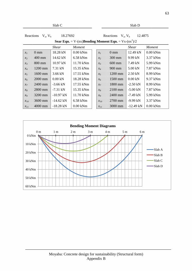
63
Moyaba: Concrete design for sustainability (Structural form)
Appendix B
Slab C
Slab D
Reactions Va, Vb 18.27692
Reactions Va, Vb 12.4875
Sear Eqn. = V-(nx)Bending Moment Eqn. = Vx-(nx
2)/2
Shear Moment
Shear Moment
x1 0 mm 18.28 kN 0.00 kNm
x1 0 mm 12.49 kN 0.00 kNm
x2 400 mm 14.62 kN 6.58 kNm
x2 300 mm 9.99 kN 3.37 kNm
x3 800 mm 10.97 kN 11.70 kNm
x3 600 mm 7.49 kN 5.99 kNm
x4 1200 mm 7.31 kN 15.35 kNm
x4 900 mm 5.00 kN 7.87 kNm
x5 1600 mm 3.66 kN 17.55 kNm
x5 1200 mm 2.50 kN 8.99 kNm
x6 2000 mm 0.00 kN 18.28 kNm
x6 1500 mm 0.00 kN 9.37 kNm
x7 2400 mm -3.66 kN 17.55 kNm
x7 1800 mm -2.50 kN 8.99 kNm
x8 2800 mm -7.31 kN 15.35 kNm
x8 2100 mm -5.00 kN 7.87 kNm
x9 3200 mm -10.97 kN 11.70 kNm
x9 2400 mm -7.49 kN 5.99 kNm
x10 3600 mm -14.62 kN 6.58 kNm
x10 2700 mm -9.99 kN 3.37 kNm
x11 4000 mm -18.28 kN 0.00 kNm
x11 3000 mm -12.49 kN 0.00 kNm
0 kNm
10 kNm
20 kNm
30 kNm
40 kNm
50 kNm
60 kNm
0 m 1 m 2 m 3 m 4 m 5 m 6 m
Bending Moment Diagrams
Slab A
Slab B
Slab C
Slab D
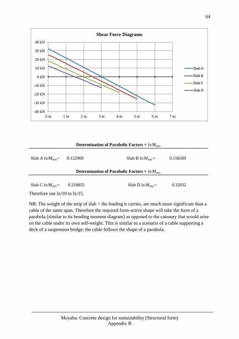
64
Moyaba: Concrete design for sustainability (Structural form)
Appendix B
Determination of Parabolic Factors = lx/Mmax
Slab A lx/Mmax= 0.122969
Slab B lx/Mmax= 0.156509
Determination of Parabolic Factors = lx/Mmax
Slab C lx/Mmax= 0.218855
Slab D lx/Mmax= 0.32032
Therefore use lx/10 to lx/15.
NB: The weight of the strip of slab + the loading it carries, are much more significant than a
cable of the same span. Therefore the required form-active shape will take the form of a
parabola (similar to its bending moment diagram) as opposed to the catenary that would arise
on the cable under its own self-weight. This is similar to a scenario of a cable supporting a
deck of a suspension bridge; the cable follows the shape of a parabola.
-40 kN
-30 kN
-20 kN
-10 kN
0 kN
10 kN
20 kN
30 kN
40 kN
0 m 1 m 2 m 3 m 4 m 5 m 6 m 7 m
Shear Force Diagrams
Slab A
Slab B
Slab C
Slab D
65
Moyaba: Concrete design for sustainability (Structural form)
Appendix C
Appendix C - Optimisation of Solid Slabs, Slab A
and Slab D
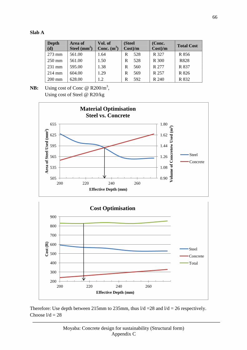
66
Moyaba: Concrete design for sustainability (Structural form)
Appendix C
Slab A
Depth
(d) Area of
Steel (mm2)
Vol. of
Conc. (m3)
(Steel
Cost)/m (Conc.
Cost)/m Total Cost
273 mm 561.00 1.64 R 528
R 327 R 856
250 mm 561.00 1.50 R 528
R 300 R828
231 mm 595.00 1.38 R 560
R 277 R 837
214 mm 604.00 1.29 R 569
R 257 R 826
200 mm 628.00 1.2 R 592 R 240 R 832
NB: Using cost of Conc @ R200/m3,
Using cost of Steel @ R20/kg
Therefore: Use depth between 215mm to 235mm, thus l/d =28 and l/d = 26 respectively.
Choose l/d = 28
0.90
1.08
1.26
1.44
1.62
1.80
505
535
565
595
625
655
200 220 240 260
Vo
lum
e o
f C
on
crete
w U
sed
(m
3)
Are
a o
f S
teel
Use
d (
mm
2)
Effective Depth (mm)
Material Optimisation
Steel vs. Concrete
Steel
Concrete
200
300
400
500
600
700
800
900
200 220 240 260
Co
st (
R)
Effective Depth (mm)
Cost Optimisation
Steel
Concrete
Total
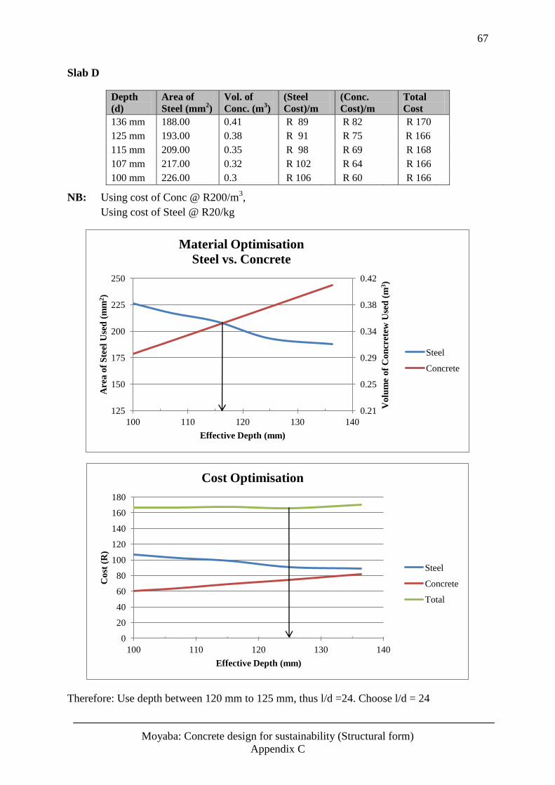
67
Moyaba: Concrete design for sustainability (Structural form)
Appendix C
Slab D
Depth
(d) Area of
Steel (mm2)
Vol. of
Conc. (m3)
(Steel
Cost)/m (Conc.
Cost)/m Total
Cost
136 mm 188.00 0.41 R 89
R 82 R 170
125 mm 193.00 0.38 R 91
R 75 R 166
115 mm 209.00 0.35 R 98
R 69 R 168
107 mm 217.00 0.32 R 102
R 64 R 166
100 mm 226.00 0.3 R 106 R 60 R 166
NB: Using cost of Conc @ R200/m3,
Using cost of Steel @ R20/kg
Therefore: Use depth between 120 mm to 125 mm, thus l/d =24. Choose l/d = 24
0.21
0.25
0.29
0.34
0.38
0.42
125
150
175
200
225
250
100 110 120 130 140
Vo
lum
e o
f C
on
cret
ew U
sed
(m
3)
Are
a o
f S
teel
Use
d (
mm
2)
Effective Depth (mm)
Material Optimisation
Steel vs. Concrete
Steel
Concrete
0
20
40
60
80
100
120
140
160
180
100 110 120 130 140
Co
st (
R)
Effective Depth (mm)
Cost Optimisation
Steel
Concrete
Total
68
Moyaba: Concrete design for sustainability (Structural form)
Appendix D
Appendix D - Form-Active Slab Design
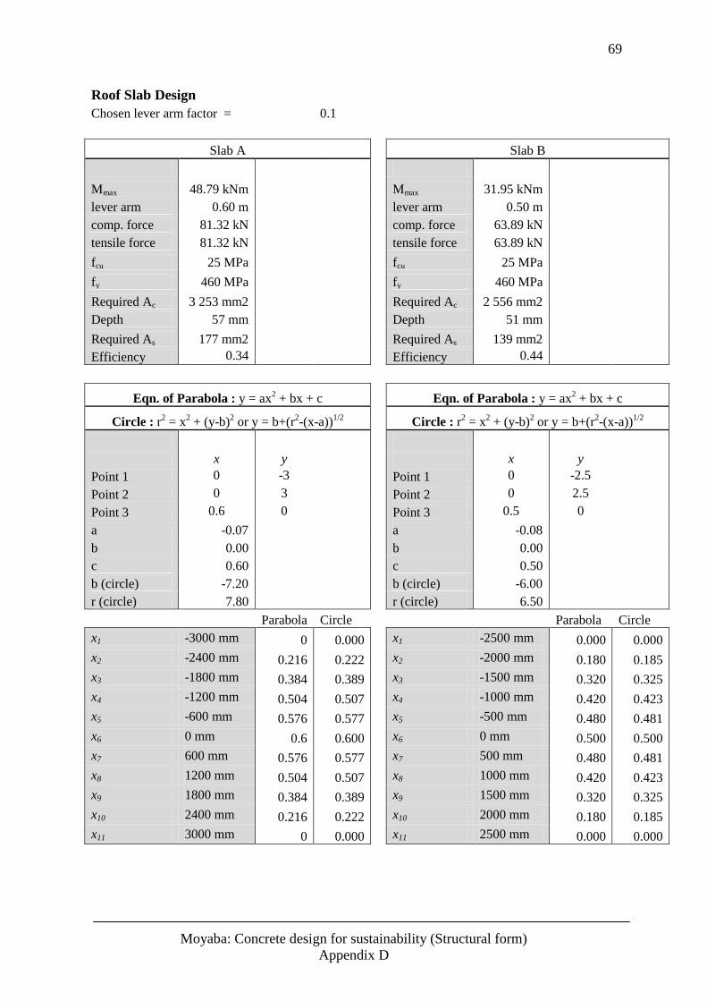
69
Moyaba: Concrete design for sustainability (Structural form)
Appendix D
Roof Slab Design
Chosen lever arm factor = 0.1
Slab A
Slab B
Mmax 48.79 kNm
Mmax 31.95 kNm
lever arm 0.60 m
lever arm 0.50 m
comp. force 81.32 kN
comp. force 63.89 kN
tensile force 81.32 kN
tensile force 63.89 kN
fcu 25 MPa
fcu 25 MPa
fy 460 MPa
fy 460 MPa
Required Ac 3 253 mm2
Required Ac 2 556 mm2
Depth 57 mm
Depth 51 mm
Required As 177 mm2
Required As 139 mm2
Efficiency 0.34
Efficiency 0.44
Eqn. of Parabola : y = ax
2 + bx + c
Eqn. of Parabola : y = ax
2 + bx + c
Circle : r2 = x
2 + (y-b)
2 or y = b+(r
2-(x-a))
1/2
Circle : r
2 = x
2 + (y-b)
2 or y = b+(r
2-(x-a))
1/2
x y
x y
Point 1 0 -3
Point 1 0 -2.5
Point 2 0 3
Point 2 0 2.5
Point 3 0.6 0
Point 3 0.5 0
a -0.07
a -0.08
b 0.00
b 0.00
c 0.60
c 0.50
b (circle) -7.20
b (circle) -6.00
r (circle) 7.80
r (circle) 6.50
Parabola Circle
Parabola Circle
x1 -3000 mm 0 0.000
x1 -2500 mm 0.000 0.000
x2 -2400 mm 0.216 0.222
x2 -2000 mm 0.180 0.185
x3 -1800 mm 0.384 0.389
x3 -1500 mm 0.320 0.325
x4 -1200 mm 0.504 0.507
x4 -1000 mm 0.420 0.423
x5 -600 mm 0.576 0.577
x5 -500 mm 0.480 0.481
x6 0 mm 0.6 0.600
x6 0 mm 0.500 0.500
x7 600 mm 0.576 0.577
x7 500 mm 0.480 0.481
x8 1200 mm 0.504 0.507
x8 1000 mm 0.420 0.423
x9 1800 mm 0.384 0.389
x9 1500 mm 0.320 0.325
x10 2400 mm 0.216 0.222
x10 2000 mm 0.180 0.185
x11 3000 mm 0 0.000
x11 2500 mm 0.000 0.000
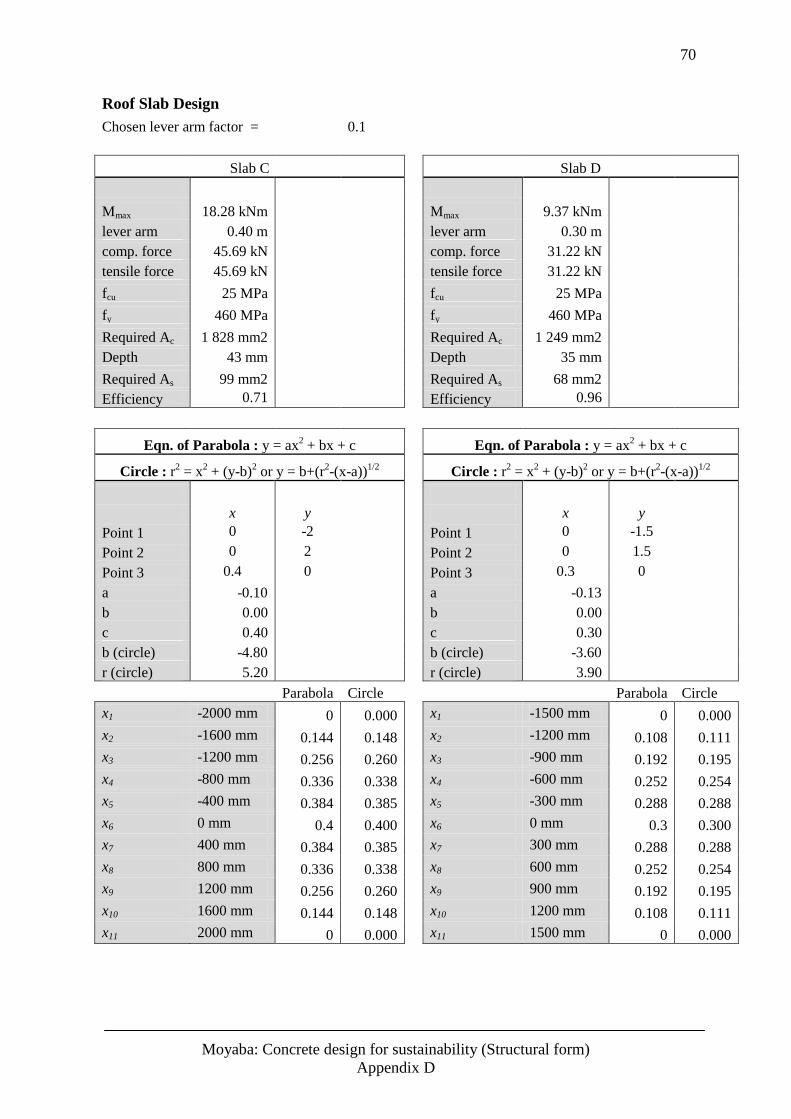
70
Moyaba: Concrete design for sustainability (Structural form)
Appendix D
Roof Slab Design
Chosen lever arm factor = 0.1
Slab C
Slab D
Mmax 18.28 kNm
Mmax 9.37 kNm
lever arm 0.40 m
lever arm 0.30 m
comp. force 45.69 kN
comp. force 31.22 kN
tensile force 45.69 kN
tensile force 31.22 kN
fcu 25 MPa
fcu 25 MPa
fy 460 MPa
fy 460 MPa
Required Ac 1 828 mm2
Required Ac 1 249 mm2
Depth 43 mm
Depth 35 mm
Required As 99 mm2
Required As 68 mm2
Efficiency 0.71
Efficiency 0.96
Eqn. of Parabola : y = ax
2 + bx + c
Eqn. of Parabola : y = ax
2 + bx + c
Circle : r2 = x
2 + (y-b)
2 or y = b+(r
2-(x-a))
1/2
Circle : r
2 = x
2 + (y-b)
2 or y = b+(r
2-(x-a))
1/2
x y
x y
Point 1 0 -2
Point 1 0 -1.5
Point 2 0 2
Point 2 0 1.5
Point 3 0.4 0
Point 3 0.3 0
a -0.10
a -0.13
b 0.00
b 0.00
c 0.40
c 0.30
b (circle) -4.80
b (circle) -3.60
r (circle) 5.20
r (circle) 3.90
Parabola Circle
Parabola Circle
x1 -2000 mm 0 0.000
x1 -1500 mm 0 0.000
x2 -1600 mm 0.144 0.148
x2 -1200 mm 0.108 0.111
x3 -1200 mm 0.256 0.260
x3 -900 mm 0.192 0.195
x4 -800 mm 0.336 0.338
x4 -600 mm 0.252 0.254
x5 -400 mm 0.384 0.385
x5 -300 mm 0.288 0.288
x6 0 mm 0.4 0.400
x6 0 mm 0.3 0.300
x7 400 mm 0.384 0.385
x7 300 mm 0.288 0.288
x8 800 mm 0.336 0.338
x8 600 mm 0.252 0.254
x9 1200 mm 0.256 0.260
x9 900 mm 0.192 0.195
x10 1600 mm 0.144 0.148
x10 1200 mm 0.108 0.111
x11 2000 mm 0 0.000
x11 1500 mm 0 0.000
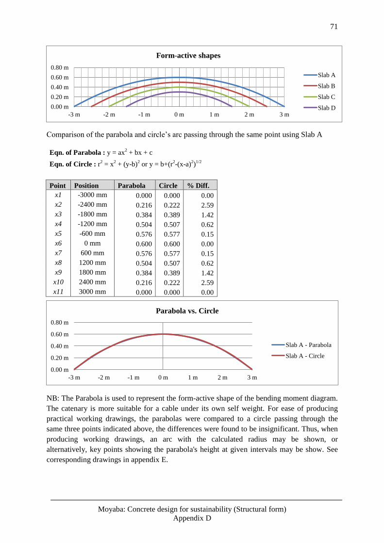
71
Moyaba: Concrete design for sustainability (Structural form)
Appendix D
Comparison of the parabola and circle’s arc passing through the same point using Slab A
Eqn. of Parabola : y = ax2 + bx + c
Eqn. of Circle : r2 = x
2 + (y-b)
2 or y = b+(r
2-(x-a)
2)
1/2
Point Position Parabola Circle % Diff. x1 -3000 mm 0.000 0.000 0.00 x2 -2400 mm 0.216 0.222 2.59 x3 -1800 mm 0.384 0.389 1.42 x4 -1200 mm 0.504 0.507 0.62 x5 -600 mm 0.576 0.577 0.15 x6 0 mm 0.600 0.600 0.00 x7 600 mm 0.576 0.577 0.15 x8 1200 mm 0.504 0.507 0.62 x9 1800 mm 0.384 0.389 1.42 x10 2400 mm 0.216 0.222 2.59 x11 3000 mm 0.000 0.000 0.00
NB: The Parabola is used to represent the form-active shape of the bending moment diagram.
The catenary is more suitable for a cable under its own self weight. For ease of producing
practical working drawings, the parabolas were compared to a circle passing through the
same three points indicated above, the differences were found to be insignificant. Thus, when
producing working drawings, an arc with the calculated radius may be shown, or
alternatively, key points showing the parabola's height at given intervals may be show. See
corresponding drawings in appendix E.
0.00 m
0.20 m
0.40 m
0.60 m
0.80 m
-3 m -2 m -1 m 0 m 1 m 2 m 3 m
Form-active shapes
Slab A
Slab B
Slab C
Slab D
0.00 m
0.20 m
0.40 m
0.60 m
0.80 m
-3 m -2 m -1 m 0 m 1 m 2 m 3 m
Parabola vs. Circle
Slab A - Parabola
Slab A - Circle
72
Moyaba: Concrete design for sustainability (Structural form)
Appendix E
Appendix E - Drawings
Related Documents