Faculty of Engineering Department of Mechanical Engineering Study and Design of an Actuated Below-Knee Prosthesis Graduation thesis submitted in partial fulfillment of the requirements for the degree of Master in Applied Sciences and Engineering: Electro-Mechanical Engineering, Mechanical Engineering Joost Geeroms Promotor: Prof. dr. ir. Dirk Lefeber Copromotor: Prof. dr. ir. Bram Vanderborght Advisor: Pierre Cherelle JUNE 2011

Welcome message from author
This document is posted to help you gain knowledge. Please leave a comment to let me know what you think about it! Share it to your friends and learn new things together.
Transcript
Faculty of EngineeringDepartment of Mechanical Engineering
Study and Design of an ActuatedBelow-Knee ProsthesisGraduation thesis submitted in partial fulfillment of therequirements for the degree of Master in Applied Sciences and Engineering:Electro-Mechanical Engineering, Mechanical Engineering
Joost Geeroms
Promotor: Prof. dr. ir. Dirk LefeberCopromotor: Prof. dr. ir. Bram Vanderborght
Advisor: Pierre Cherelle
JUNE 2011

Faculteit IngenieurswetenschappenVakgroep Toegepaste Mechanica
Studie en Ontwerp van eenGeactueerde OnderbeenprotheseProefschrift ingediend met het oog op het behalenvan de graad van Master in de Ingenieurswetenschappen:Werktuigkunde-Elektrotechniek, Werktuigbouwkunde
Joost Geeroms
Promotor: Prof. dr. ir. Dirk LefeberCopromotor: Prof. dr. ir. Bram Vanderborght
Begeleider: Pierre Cherelle
JUNI 2011

Acknowledgements
This was a beautiful project to work on, not only challenging and enriching, but it is alsosatisfying to know that the work done, even if it's only a very small part of the puzzle, caneventually help people walk with less e�ort.
I would like to thank my promotor professor Lefeber and copromotor professor Vanderborghtfor enabling me make my contribution to this project. Many thanks to Pierre who helped methroughout the whole process of making this thesis work, from the �rst simulation to the lastwritten part. Also, every other professor, assistant, technician, doctor, PhD student or fellowstudent in the department who helped me when I had questions on whatever subject, it has beengreatly appreciated.
The rest of the gratitude I have left goes to the people that read my thesis or got involvedin any other way, and to my girlfriend, who often insisted that I made backups of my work, likeshe also did just before my laptop crashed...
Joost Geeroms
3

Abstract
Almost all of the transtibial prostheses, which are for below-knee amputations, that are availableon the market are purely passive devices. They store energy in an elastic element during thebeginning of a step and release it at the end in order to move the body forwards. The mainproblem with these prostheses is that only the energy that has been stored in the elastic elementis used for the push-o�, unlike for sound ankles where the muscles provide extra energy. Thereare a few prostheses who use active components for this energy input, but these are still inresearch phase.
The problem with transtibial prostheses that use a DC motor for this energy input is thatthis motor has to deliver the energy in a small period of time and thus requires high power. Theobjective of this thesis is to study the possibility of storing energy during an other part of thegait cycle and then releasing it when necessary. In this case the energy is stored in a spring usinga motor with a relatively low rated power. The di�culty with this concept is that it requiresa rather complicated mechanical system with di�erent lever arms from which the position withrespect to each other has to be lockable.
In this thesis �rst a simulation was made to get a �rst estimate of the required motor powerand the properties of the other components. The goal of this simulation is to achieve a modelthat is able to provide the same characteristics as a sound ankle and that is ideally adaptablefor di�erent walking conditions.
The next step was to develop this �rst model, with a driving system and all of the othercomponents present. This design was then to be further optimised to become as light andcompact as possible, while being able to withstand the forces and torques that are exerted bythe driving system and the body weight. These static and dynamic forces are examined in astress analysis.
The result of this research is a prosthesis that can be described in short as: (for a person of75 kg)
� A prosthesis mimicking the sound ankle behaviour, having an energy output that is equallyhigh and that occurs at the right time.
� A prosthesis with a driving system consisting of a motor with a rated power of only 30 W,a gearhead and a ball screw mechanism.
� A system for which the properties can be changed by altering the pretensions of the springsand the motor operation.
� A total mass of the prosthesis of under 2 kg. The batteries are not included in thiscalculation.
� A compact design which is able to withstand all the acting forces.
� An energy consumption of 28.9 J per step.
4

Samenvatting
Bijna alle beenprothesen die beschikbaar zijn in de handel zijn puur passieve apparaten.Deze slaan energie op in een elastisch element tijdens het eerste deel van een stap en laten dezevrij bij het einde zodat deze kan gebruikt worden om het lichaam voorwaarts te bewegen. Hetbelangrijkste probleem met deze prothesen is dat enkel de energie die in het elastisch elementgestockeerd werd, gebruikt wordt voor de push-o�. Dit is niet het geval bij een gezonde enkel,waar de spieren extra energie leveren. Er zijn enkele prothesen die actieve elementen gebruikenvoor deze extra energie, maar deze zijn nog steeds in onderzoeksfase.
Het probleem met prothesen die een DC-motor gebruiken voor deze extra energie is dat demotor deze energie moet leveren in een kleine tijdsspanne en dat dus een hoog vermogen vereistis. Het doel van deze thesis is de mogelijkheid om energie te stockeren in een ander ogenblik vande stapcyclus en deze op het gepaste moment te laten vrijkomen. In dit geval wordt de energieopgeslaan in een veer door gebruik te maken van een motor met een relatief laag vermogen. Demoeilijkheid in dit concept is dat er nood is aan een eerder ingewikkeld mechanisch systeemmet verschillende hefboomsarmen van welke de positie ten opzichte van elkaar moet kunnengeblokkeerd worden.
In deze thesis werd eerst een simulatie gemaakt om een eerste schatting te krijgen van hetnodige motorvermogen en de eigenschappen van de andere componenten. Het doel van dezesimulatie is een model te verkrijgen dat in staat is hetzelfde gedrag als een gezonde enkel tevertonen en dat in het ideale geval aanpasbaar is voor verschillende stapcondities.
De volgende stap was dit eerste model te ontwikkelen, met een aandrijfsysteem en al deandere nodige componenten aanwezig. Dit design werd dan verder geoptimaliseerd om zo lichten compact mogelijk te zijn, terwijl het toch bestand moet blijven tegen de krachten en koppelsdie uitgeoefend worden door het aandrijfsysteem en het lichaamsgewicht. Deze statische endynamische krachten werden bestudeerd door middel van een spanningsanalyse.
Het resultaat van dit onderzoek is een prothese die in het kort op de volgende manierbeschreven kan worden: (voor een persoon van 75 kg)
� Een prothese die het gedrag van een gezonde enkel benaderd, met een energieoutput dieeven hoog is en op hetzelfde moment optreedt.
� Een prothese met een aandrijfsysteem dat bestaat uit een motor met een vermogen vanslechts 30W, een gearhead en een ballscrewmechanisme.
� Een systeem waarvan de eigenschappen kunnen aangepast worden door de voorspanningenvan de veren en de motoroperatie aan te passen.
� Een totale massa van minder dan 2 kg. De batterijen zijn niet meegenomen in deze bereken-ing.
� Een compact ontwerp dat in staat is alle optredende krachten te weerstaan.
� Een energieverbruik van 28,5 J per stap.
5

Résumé
Presque toutes les prothèses trans-tibial disponibles sur le marché sont des appareils passifs.Ces prothèses stockent de l'énergie dans un élement élastique pendant la première phase d'unpas et la relachent ensuite pour propulser le corps. Le problème le plus important avec cesprothèses est que seule l'énergie qui a été stockée dans l'élement élastique est utilisée pour lapropulsion. Dans le cas d'une cheville saine en revanche les muscles du mollet fournissent l'énergiesupplémentaire. Certaines prothèses utilisent des composants actifs pour acquérir cette énergie,mais celles-ci sont encore en une phase de développement.
Les prothèses utilisant un moteur à courant continu pour cette énergie supplémentaire con-naissent le problème suivant : ce moteur doit o�rir cette énergie durant une courte periode, etce moteur doit être très puissant. L'objectif de ce mémoire est d'examiner si il est possible destocker de l'énergie pendant une phase précise de la marche et de relâcher cette énergie pendantune autre phase. Dans le cas présent, l'énergie est stockée dans un ressort en utilisant un moteurde puissance raisonnable. La di�culté de ce concept est qu'un système mécanique assez com-pliqué est nécessaire, avec des bras de levier dont la position par rapport aux autres doit pouvoirêtre bloquée.
Tout d'abord, une simulation a été faite pour obtenir une estimation de la puissance nécessairedu moteur et des caractéristiques des autres composants. L'obectif de cette simulation est dedévelopper un modèle capable de fournir les mèmes caractéristiques qu'une cheville saine et qui,dans le cas ideal, peut être adapté aux conditions de marche di�erentes.
Ensuite, ce premier modèle a été développé avec une système motorisé et la présence de tousles autres composants. Ce design a ensuite été optimisé pour le rendre le plus léger et le pluscompact possible, et en mème temps capable de résister aux forces et aux couples qui sont exercéspar la motorisation et le poids corporel. Ces forces statiques et dynamiques sont examinées dansune analyse de résistance des matériaux.
Le résultat de cette recherche est une prothèse qui peut être décrite en bref comme: (pourune personne de 75 kg)
� Une prothèse capable d'imiter le comportement d'une cheville saine, avec une productiond'énergie qui est aussi élevée et qui a lieu au moment propice.
� Une motorisation d'une puissance de seulement 30W, un réducteur et un mécanisme de visà billes.
� Une système dont lequel les characteristiques peuvent être adaptés par varier la précon-
treinte des ressorts et l'opération du moteur
� Une masse totale de la prothèse de moins que 2 kg. Les batteries non-incluses.
� Un design compact et capable de résister à toutes les forces agissantes.
� Une consommation d'énergie de 28.9 J par pas.
6

Abbreviations
DF: DorsiFlexion
E: Energy
F: Force
FF: Foot Flat
HO: Heel O�
IC: Initial Contact
MDF: Maximum DorsiFlexion
P: Power
PF: PlantarFlexion
T: Torque
TO: Toe O�
TT: TransTibial
ω: Rotational speed
7
Contents
1 Biomechanics of human walking 9
1.1 Basics . . . . . . . . . . . . . . . . . . . . . . . . . . . . . . . . . . . . . . . . . . 91.1.1 Gait cycle terminology . . . . . . . . . . . . . . . . . . . . . . . . . . . . . 91.1.2 Key phases . . . . . . . . . . . . . . . . . . . . . . . . . . . . . . . . . . . 11
1.2 Ankle characteristics . . . . . . . . . . . . . . . . . . . . . . . . . . . . . . . . . . 151.2.1 Ankle terminology . . . . . . . . . . . . . . . . . . . . . . . . . . . . . . . 151.2.2 Ankle behaviour . . . . . . . . . . . . . . . . . . . . . . . . . . . . . . . . 15
2 Transtibial prostheses: State of the art 19
2.1 De�nition . . . . . . . . . . . . . . . . . . . . . . . . . . . . . . . . . . . . . . . . 192.2 Conventional feet . . . . . . . . . . . . . . . . . . . . . . . . . . . . . . . . . . . . 192.3 Energy storing and returning feet . . . . . . . . . . . . . . . . . . . . . . . . . . . 202.4 Active prostheses . . . . . . . . . . . . . . . . . . . . . . . . . . . . . . . . . . . . 23
2.4.1 Prostheses with arti�cial muscles . . . . . . . . . . . . . . . . . . . . . . . 242.4.2 Electrically powered prostheses . . . . . . . . . . . . . . . . . . . . . . . . 25
3 Design of an actuated below-knee prosthesis 28
3.1 Development of the concept . . . . . . . . . . . . . . . . . . . . . . . . . . . . . . 283.1.1 Previous concepts . . . . . . . . . . . . . . . . . . . . . . . . . . . . . . . 283.1.2 First concept . . . . . . . . . . . . . . . . . . . . . . . . . . . . . . . . . . 303.1.3 Optimization of concept . . . . . . . . . . . . . . . . . . . . . . . . . . . . 32
3.2 Step by step explanation of �nal concept . . . . . . . . . . . . . . . . . . . . . . . 323.2.1 Phase 1 . . . . . . . . . . . . . . . . . . . . . . . . . . . . . . . . . . . . . 323.2.2 Phase 2 . . . . . . . . . . . . . . . . . . . . . . . . . . . . . . . . . . . . . 343.2.3 Unlocking . . . . . . . . . . . . . . . . . . . . . . . . . . . . . . . . . . . . 353.2.4 Phase 3 . . . . . . . . . . . . . . . . . . . . . . . . . . . . . . . . . . . . . 363.2.5 Swing phase . . . . . . . . . . . . . . . . . . . . . . . . . . . . . . . . . . . 37
3.3 Adaptability . . . . . . . . . . . . . . . . . . . . . . . . . . . . . . . . . . . . . . . 383.3.1 Changing the spring pretension . . . . . . . . . . . . . . . . . . . . . . . . 383.3.2 Changing the motor operation . . . . . . . . . . . . . . . . . . . . . . . . 39
3.4 Choice of components . . . . . . . . . . . . . . . . . . . . . . . . . . . . . . . . . 413.4.1 Driving system . . . . . . . . . . . . . . . . . . . . . . . . . . . . . . . . . 413.4.2 Motor . . . . . . . . . . . . . . . . . . . . . . . . . . . . . . . . . . . . . . 413.4.3 Springs . . . . . . . . . . . . . . . . . . . . . . . . . . . . . . . . . . . . . 463.4.4 Locking mechanism . . . . . . . . . . . . . . . . . . . . . . . . . . . . . . 493.4.5 Conclusions . . . . . . . . . . . . . . . . . . . . . . . . . . . . . . . . . . . 51
3.5 Control and electronics . . . . . . . . . . . . . . . . . . . . . . . . . . . . . . . . . 523.5.1 Sensors . . . . . . . . . . . . . . . . . . . . . . . . . . . . . . . . . . . . . 523.5.2 Sensors for operation . . . . . . . . . . . . . . . . . . . . . . . . . . . . . . 523.5.3 Motor control . . . . . . . . . . . . . . . . . . . . . . . . . . . . . . . . . . 553.5.4 Motor autonomy . . . . . . . . . . . . . . . . . . . . . . . . . . . . . . . . 58
3.6 Prosthesis design . . . . . . . . . . . . . . . . . . . . . . . . . . . . . . . . . . . . 603.6.1 Initial design phase . . . . . . . . . . . . . . . . . . . . . . . . . . . . . . . 613.6.2 Final design . . . . . . . . . . . . . . . . . . . . . . . . . . . . . . . . . . . 62
4 General conclusions and future work 83
References 85
8

1 Biomechanics of human walking
1.1 Basics
1.1.1 Gait cycle terminology
The gait cycle can be de�ned as the time interval between two consecutive occurrences of the
same recurring event during walking. This event can for example be the moment the right foot
touches the ground. The gait cycle can be subdivided into two periods for each leg: the stance
and the swing period. The stance period is de�ned by the contact between the leg and the
ground, and during the swing period there's no contact with the ground. The stance is about
60% of the total cycle. This indicates that there's an overlap between the stance periods of the
2 legs, and during 20% of the gait both legs have ground contact [12].
Figure 1.1: Overview of the human gait cycle.
There are three reference planes that are used when talking about human anatomy. The
sagittal plane, the frontal plane and the transverse plane are depicted in Fig.1.2. For most of
this work, all of the movements and forces are projected onto the sagittal plane.
9

Figure 1.2: The anatomical position and orientation with the three reference planes.
There are two important terms to describe distances in relation to human gait: step and
stride. The step length is de�ned as the distance between two consecutive ground contacts of
one of the feet. The stride on the other hand is the distance between two consecutive ground
contacts of one foot and the other one. This means that the stride is the sum of the left step
and the right step, and in an ideal gait pattern these two are the same. The determination of
these distances are necessary in order to be able to de�ne walking speeds afterwards.
Figure 1.3: Stance and stride.
Similarly to the distance, there are a few important terms to describe time and speeds in
relation to the human gait. The number of steps a person takes during a certain amount of time
is his cadence. The problem with this variable is that since the common unit is steps per minute,
it measures half cycles per unit of time, which is not considered to be scienti�cally acceptable.
10
Another reason is that for people with pathological gait, left step and right step is not necessarily
equally large. Better is to use the cycle time or stride time, which is the time it takes the person
to move two steps, or one stride. It's relation to the cadence is:
cycle time (s) =120
cadence (steps/minute)(1.1)
From this cycle time the walking speed can be calculated if the length of one stride is divided
by it:
speed (m/s) =stride length (m)
cycle time (s)(1.2)
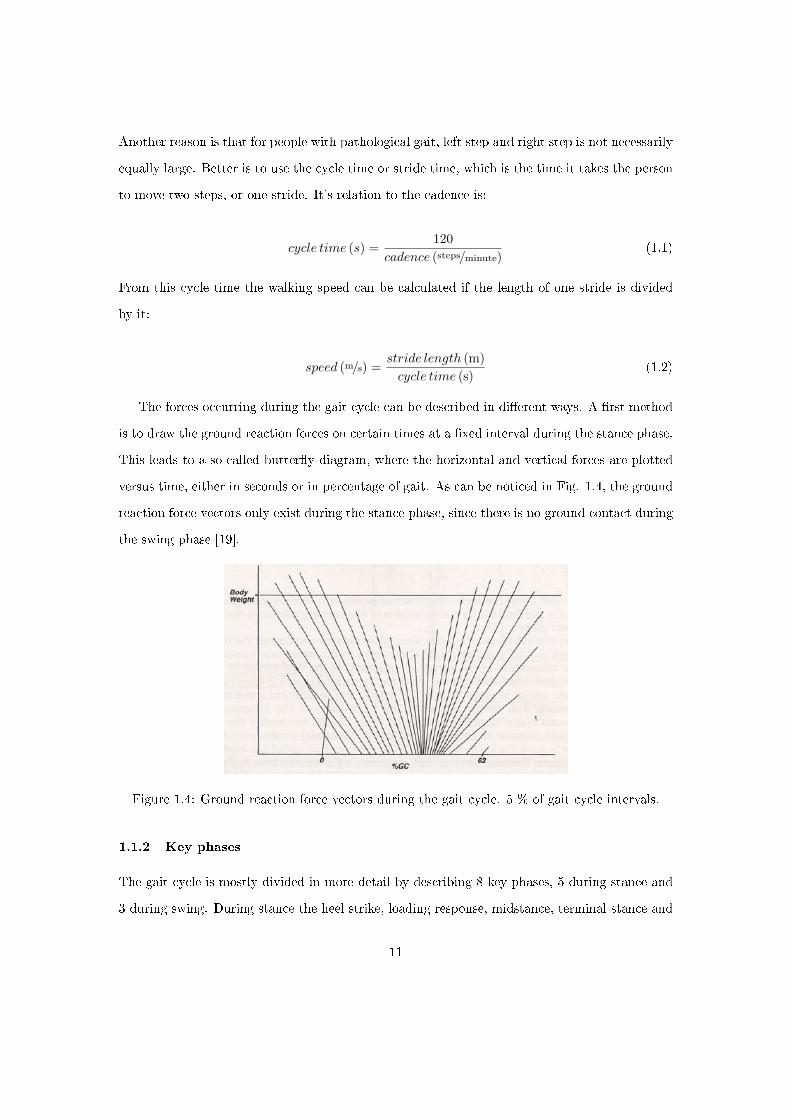
The forces occurring during the gait cycle can be described in di�erent ways. A �rst method
is to draw the ground reaction forces on certain times at a �xed interval during the stance phase.
This leads to a so-called butter�y diagram, where the horizontal and vertical forces are plotted
versus time, either in seconds or in percentage of gait. As can be noticed in Fig. 1.4, the ground
reaction force vectors only exist during the stance phase, since there is no ground contact during
the swing phase [19].
Figure 1.4: Ground reaction force vectors during the gait cycle. 5 % of gait cycle intervals.
1.1.2 Key phases
The gait cycle is mostly divided in more detail by describing 8 key phases, 5 during stance and
3 during swing. During stance the heel strike, loading response, midstance, terminal stance and
11
pre-swing occur, during swing acceleration, midswing and deceleration.
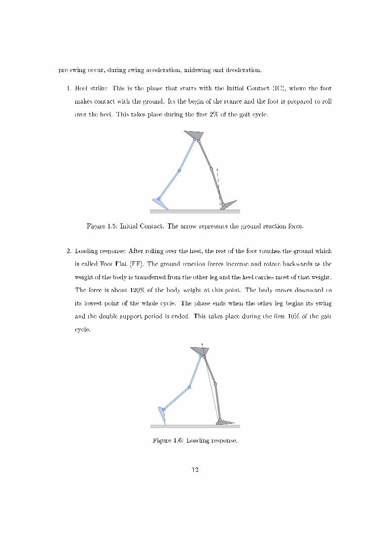
1. Heel strike: This is the phase that starts with the Initial Contact (IC), where the foot
makes contact with the ground. Its the begin of the stance and the foot is prepared to roll
over the heel. This takes place during the �rst 2% of the gait cycle.
Figure 1.5: Initial Contact. The arrow represents the ground reaction force.
2. Loading response: After rolling over the heel, the rest of the foot touches the ground which
is called Foot Flat (FF). The ground reaction forces increase and rotate backwards as the
weight of the body is transferred from the other leg and the heel carries most of that weight.
The force is about 120% of the body weight at this point. The body moves downward to
its lowest point of the whole cycle. The phase ends when the other leg begins its swing
and the double support period is ended. This takes place during the �rst 10% of the gait
cycle.
Figure 1.6: Loading response.
12

3. Mid Stance: The whole foot keeps its contact with the ground while the other leg is moved
forward. The ground reaction forces rotate forward as the body rotates around the ankle
joint. The body climbs to it's highest point of the gait cycle while it's weight is distributed
over the whole foot. The phase ends when the two legs are adjecent and the ground reaction
force is pointing upward.
Figure 1.7: Mid Stance.
4. Terminal stance: The weight of the body is transferred to the front of the foot as the
center of gravity of the body lies in front of the ankle. The ground reaction force rotates
further forward and it grows as push-o� is generated: the whole body is pushed forward
by the limb. This phase ends at Heel O� (HO), where the contact between the heel and
the ground is ended.
Figure 1.8: The initial contact of the other foot. This is the event that separates terminal stancefrom pre-swing.
5. Pre-swing: This phase starts with the IC of the other leg and the end of the single limb
13

support phase. The leg and foot now rotate around the toe joint. The ground reaction
force starts to drop since the weight is transferred to the other leg (weight release), while
it continues to rotate forward. This phase as well as the stance phase end at Toe O� (TO),
when the ground contact of the toe is ended.
Figure 1.9: Toe o�. This indicates the end of the pre-swing phase.
6. Initial swing or acceleration: The foot is lifted from the ground and the leg is accelerated
forward while the weight of the body is carried by the other leg.
7. Midswing: The leg is adjecent to the other leg while it continues to swing forward.
Figure 1.10: The center of the swing phase. The two feet are next to each other.
8. Terminal swing or deceleration: The limb is slowed down and prepared to make ground
contact. This phase ends with IC. [12,19]
14

1.2 Ankle characteristics
1.2.1 Ankle terminology
Since the subject in this thesis is the development of a TransTibial (TT) prosthesis, and the
purpose of this device is to mimick the behaviour of a sound ankle during the gait cycle, the
terminology and characteristics of the ankle will be explained in further detail. The de�nition
of the reference planes is the same as de�ned before, with the frontal, sagittal and transverse
plane. There are di�erent terms to describe rotations about the ankle in the di�erent planes.
In the sagittal plane, the rotation which causes the toes to move upwards, closer to the leg, is
called DorsiFlexion (DF). The rotation in the other direction, so downward for the toes, is called
PlantarFlexion (PF). These rotations are used the most frequently since mostly kinematics are
studied in this plane. Rotations in the frontal plane are called inversion when the foot rotates
towards the other foot and eversion when it moves away from it. For rotations in the transverse
plane the terms are adduction for a rotation towards the other foot and abduction for the
opposite. [17]
Figure 1.11: Ankle rotations in the di�erent reference planes. Left: sagittal plane, middle: frontalplane, right: transverse plane
1.2.2 Ankle behaviour
In the past, biomechanical studies have been performed on the ankle and from those, the ankle
behaviour was described using di�erent characteristics. For this thesis work, the studies of
Winter have been used [21]. The angle of the leg and the torque around the ankle joint were
measured during the gait cycle. The important events that are reviewed before are indicated on
the �gures: IC, FF and TO. HO is not depicted on the �gures, since there's another term that
15
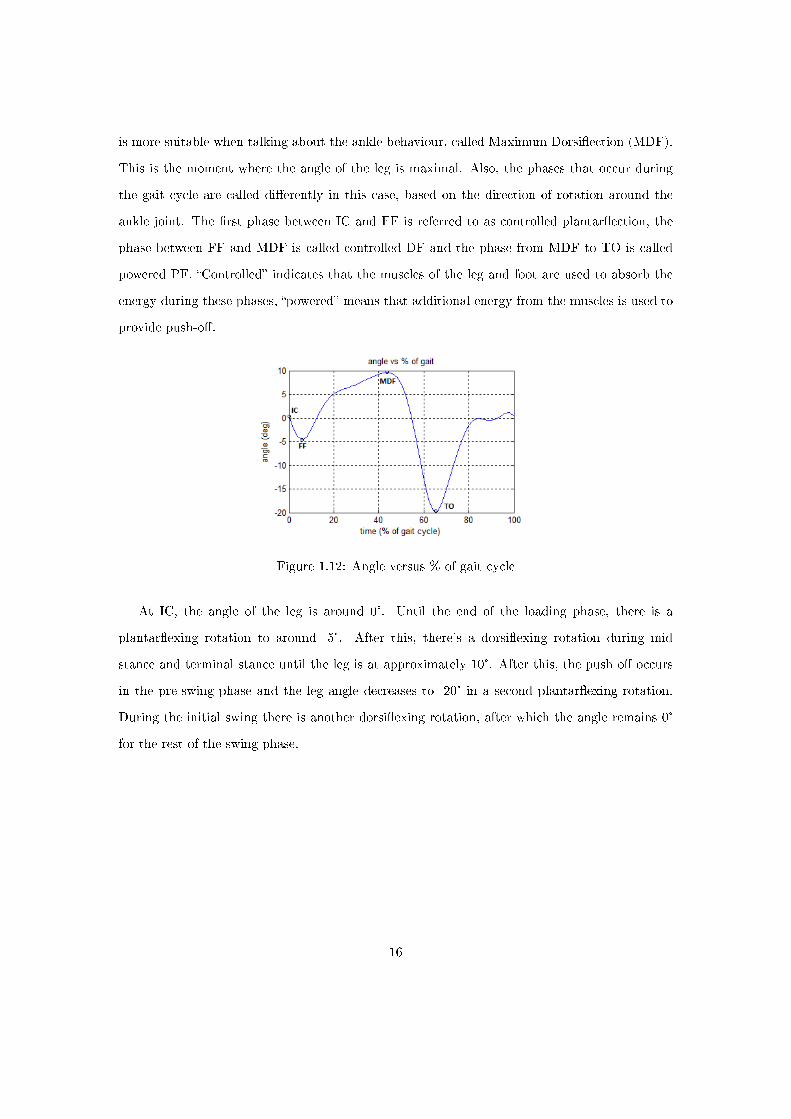
is more suitable when talking about the ankle behaviour, called Maximum Dorsi�ection (MDF).
This is the moment where the angle of the leg is maximal. Also, the phases that occur during
the gait cycle are called di�erently in this case, based on the direction of rotation around the
ankle joint. The �rst phase between IC and FF is referred to as controlled plantar�ection, the
phase between FF and MDF is called controlled DF and the phase from MDF to TO is called
powered PF. �Controlled� indicates that the muscles of the leg and foot are used to absorb the
energy during these phases, �powered� means that additional energy from the muscles is used to
provide push-o�.
Figure 1.12: Angle versus % of gait cycle
At IC, the angle of the leg is around 0°. Until the end of the loading phase, there is a
plantar�exing rotation to around -5°. After this, there's a dorsi�exing rotation during mid
stance and terminal stance until the leg is at approximately 10°. After this, the push o� occurs
in the pre-swing phase and the leg angle decreases to -20° in a second plantar�exing rotation.
During the initial swing there is another dorsi�exing rotation, after which the angle remains 0°
for the rest of the swing phase.
16

Figure 1.13: Torque versus % of gait cycle
At IC, the torque is 0 Nm, after which there will be a small dorsi�exor torque during the
loading phase. During mid stance, the torque will increase and become a plantar�exor torque.
This will continue until MDF, and then the torque will increase even more after this until it
reaches about 1.7 Nm per kg of body weight. During pre-swing, the torque drops to reach 0 Nm
at TO.
A graph that is frequently used in literature is the combination of the two previous ones (Fig.
1.14), where the torque around the ankle joint is plotted against the angle of the ankle.
Figure 1.14: Torque versus angle
The reason why this graph is considered useful by a lot of researchers is that it shows an other
important useful parameter: the ankle sti�ness. This is especially important in prosthetics, where
attempts are made to mimic the ankle behaviour by using elastic springs. These are speci�cally
used to create the same ankle sti�ness as for a healthy ankle. This will be further explained later
17

in this work.
Another variable that is interesting to look at and that can be calculated from the ankle angle
and torque is the ankle power.
P = T × α̇ (1.3)
In which the ankle P is the ankle power, T is the torque around the ankle and α̇is the ankle
angular speed. The angular speed is calculated by computing the time derivative of the ankle
angle.
α̇ =dα
dt(1.4)
Figure 1.15: Ankle power versus % of gait cycle
The graph shows that the work done between IC and MDF is negative, which means energy
is stored here, but after MDF there is a rapid increase in power, up to more than 4 Watts per
kilogram body weight. This is the power used to provide the push o�. The energy used by the
ankle during one gait cycle can be calculated by computing the integral of the power, which gives
a value of just over 0.22 J/kg body weight, which is about 16.6 J for an average person of 75 kg.
E =
�Pdt = 16.6J (1.5)
18
2 Transtibial prostheses: State of the art
2.1 De�nition
According to Black's Medical Dictionary [16], a prosthesis is �an arti�cial replacement of a missing
or malfunctioning body part�. The prostheses looked upon in this work are devices which replace
body parts after amputation, the �severance of a limb, or part of a limb, from the rest of the
body�. The term transtibial implies that the limb in this case is the lower leg, and that the
amputation happened between the knee and the ankle. The tibia is the largest bone in the lower
leg, connecting to the thigh bone at the knee joint and to the ankle joint at its other end.
2.2 Conventional feet
Until the '80s the focus in the design of prosthetic feet was on trying to restore basic walking
and enabling the amputee to ful�ll basic tasks. Examples of this can be found back to the
ancient times were wood, bronze or iron were used to make substitutes for lost limbs. A well
known example of this kind of prostheses is the simple wooden leg that was used during the dark
ages. The prostheses and materials used slowly evolved until the so-called �conventional feet�,
which were still very basic but from these prostheses onward things like weight of the prosthesis
and amputee comfort became more important. The SACH-foot, which stands for Solid Ankle-
Cushion Heel [1,8], is the most common of these conventional feet. It has been developed at the
University of California in the 1950s and has long been by far the most prescribed prosthesis in
the USA. As the name says, the prosthesis has a soft, compressible heel that �rst of all damps
the impact on the ground but also provides so called �pseudo-plantar�exion� after IC. It's not
really PF because the ankle does not change in angle but it simulates the e�ect. The �Solid
Ankle� refers to to fact that the ankle joint does not rotate, and the core of the prosthesis is a
rigid wooden keel. Though this prosthesis is an improvement with respect to earlier prostheses
and it has been used a lot, it still limits the amputee in his movements and actions. Despite this,
the prosthesis is still popular, mainly in developing countries. The reasons for this are its low
cost and weight and high reliability thanks to the lack of rotating mechanical parts.
19
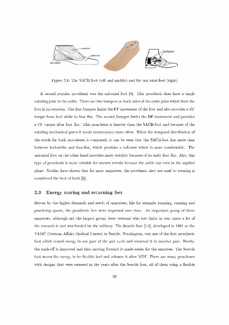
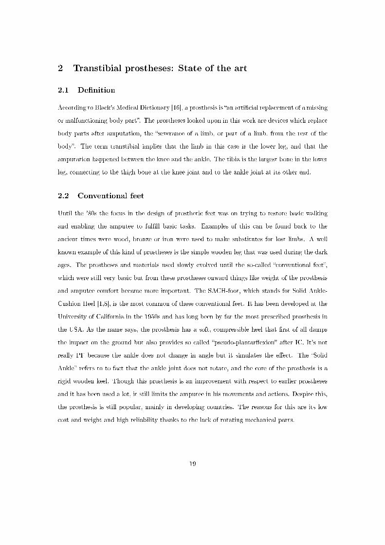
Figure 2.1: The SACH-foot (left and middle) and the uni-axial foot (right)
A second popular prosthesis was the uni-axial foot [8]. This prosthesis does have a single
rotating joint in the ankle. There are two bumpers at both sides of the ankle joint which limit the
foot in its rotation. The �rst bumper limits the PF movement of the foot and also provides a DF
torque from heel strike to foot �at. The second bumper limits the DF movement and provides
a PF torque after foot �at. This prosthesis is heavier than the SACH-foot and because of the
rotating mechanical parts it needs maintenance more often. When the temporal distribution of
the stride for both prostheses is compared, it can be seen that the SACH-foot has more time
between heel-strike and foot-�at, which provides a roll-over which is more comfortable. The
uni-axial foot on the other hand provides more stability because of its early foot �at. Also, this
type of prosthesis is more suitable for uneven terrain because the ankle can turn in the sagittal
plane. Studies have shown that for most amputees, the prosthesis they are used to wearing is
considered the best of both [8].
2.3 Energy storing and returning feet
Driven by the higher demands and needs of amputees, like for example jumping, running and
practicing sports, the prosthetic feet were improved over time. An important group of these
amputees, although not the largest group, were veterans who lost limbs in war, since a lot of
the research is and was funded by the military. The Seattle foot [1,9], developed in 1981 at the
VAMC (Veteran A�airs Medical Center) in Seattle, Washington, was one of the �rst prosthetic
foot which stored energy in one part of the gait cycle and returned it in another part. Hereby
the push-o� is improved and thus moving forward is made easier for the amputee. The Seattle
foot stores the energy in its �exible keel and releases it after MDF. There are many prostheses
with designs that were released in the years after the Seattle foot, all of them using a �exible
20

keel to store the energy. Some examples are given in Fig. 2.2.
Figure 2.2: Early ESR prostheses. A: Seattle foot B: Dynamic foot C: STEN foot D: SAFE footE: Carbon Copy foot.
Another prosthesis that was very popular, especially in developing countries because of its
simple design and low cost is the Jaipur foot. It has been developed in the city with the same
name in India. The Jaipur foot was �rst developed in the 1960s as a cheap prosthesis for victims
of landmines in India, but it evolved into a prosthesis that could compete with the other early
ESR prostheses. The prosthesis has a wooden ankle and the foot itself consists of a combination of
di�erent types of rubber. Tests measuring ground reaction forces comparing the Jaipur, Seattle
an SACH-feet showed that the Jaipur foot was experienced to be the closest to the gait of a
healthy limb [1].
Figure 2.3: The Jaipur Foot
Thanks to a better knowledge and understanding of the human gait and biomechanics, the
development of new (composite) materials and the evolution of Computer Aided Design (CAD)
and Manufacturing (CAM), new types of ESR prostheses were developed. One of the �rst types
21
was the Flex-foot, which consisted of a �exible carbon-�ber composite material. Its biomechanical
properties were better than those of the early ESR-feet and a lot of similar prostheses were built
in response. Whereas early ESR-feet tried to make parts of a prosthetic foot store energy, these
devices were designed to store as much energy as possible in the whole prosthesis. The use of
carbon-�ber material allowed the energy losses and the weight of the prostheses to be reduced,
which gave them a signi�cant advantage to earlier designs.
Figure 2.4: ESR feet. 1: Ossür Flex-footModular III, 2: Ossür Flex-foot Vari�ex, 3: Otto BockSpringlite Foot, 4: Ossur Flex-foot Talux
Rather than storing energy during stance and then releasing it in late stance, it is also possible
to use the weight of the body on initial contact to store energy and release this later in the stance
to provide a better push-o�. The Controlled Energy Storing and Returning foot (CESR foot),
developed at the university of Michigan and the University of Delft is based on this principle.
This prosthetic foot has a rotating joint in the middle of the foot which locks after heel strike.
During heel strike, a spring in the heel is compressed and the energy in this spring is released
during push-o� when the rotating joint unlocks [6].
22

Figure 2.5: CESR foot
As seen in Winter's angle-torque characteristic of able-bodied gait cycle, the ankle rotates
about 15 degrees during controlled DF while it stores energy. After this, it rotates about 30
degrees while releasing this energy. If a prosthesis should imitate this behavior, two di�erent
ankle sti�nesses would be needed for those phases. At the Vrije Universiteit Brussel, a TT
prosthesis has been developed called the Ankle-Mimicking Prosthetic foot (AMPfoot) [17]. This
device consists of a spring and a planetary gearbox, and its working principle is based on a change
in equilibrium position of the spring. Using a planetary gearbox and locking mechanisms allows
to have a di�erent transmission ratio between the rotating leg and the lever arm that extends
the spring during loading and unloading. In order to store enough energy during the loading
phase, a high torque has to be achieved at MDF, which leads to a severe drop in torque after
unlocking. Tests showed that this made it hard to walk with the prosthesis.
2.4 Active prostheses
All of the prostheses described so far use only the energy provided by the amputee himself to
mimic the behavior of a sound ankle. There is also the possibility to insert energy into the system
by using an external source of energy. The type of source can di�er, but so far two types have
been investigated in various universities: pressurised gas used to power arti�cial muscles and
electrical energy to power motors.
23
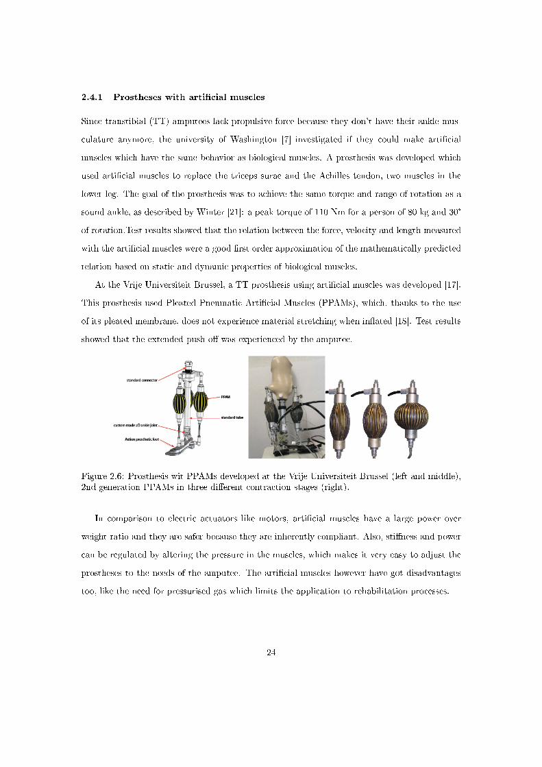
2.4.1 Prostheses with arti�cial muscles
Since transtibial (TT) amputees lack propulsive force because they don't have their ankle mus-
culature anymore, the university of Washington [7] investigated if they could make arti�cial
muscles which have the same behavior as biological muscles. A prosthesis was developed which
used arti�cial muscles to replace the triceps surae and the Achilles tendon, two muscles in the
lower leg. The goal of the prosthesis was to achieve the same torque and range of rotation as a
sound ankle, as described by Winter [21]: a peak torque of 110 Nm for a person of 80 kg and 30°
of rotation.Test results showed that the relation between the force, velocity and length measured
with the arti�cial muscles were a good �rst order approximation of the mathematically predicted
relation based on static and dynamic properties of biological muscles.
At the Vrije Universiteit Brussel, a TT prosthesis using arti�cial muscles was developed [17].
This prosthesis used Pleated Pneumatic Arti�cial Muscles (PPAMs), which, thanks to the use
of its pleated membrane, does not experience material stretching when in�ated [18]. Test results
showed that the extended push-o� was experienced by the amputee.
Figure 2.6: Prosthesis wit PPAMs developed at the Vrije Universiteit Brussel (left and middle),2nd generation PPAMs in three di�erent contraction stages (right).
In comparison to electric actuators like motors, arti�cial muscles have a large power over
weight ratio and they are safer because they are inherently compliant. Also, sti�ness and power
can be regulated by altering the pressure in the muscles, which makes it very easy to adjust the
prostheses to the needs of the amputee. The arti�cial muscles however have got disadvantages
too, like the need for pressurised gas which limits the application to rehabilitation processes.
24

2.4.2 Electrically powered prostheses
Prostheses powered be means of electrical energy are mostly still in a research phase, just like
prostheses with arti�cial muscles. A single commercially available active prosthesis is the Proprio
Foot, developed by Össur. However, The motor and the inputted energy is not used to store
additional energy for improved push-o�, but rather to adjust the properties of the prosthesis to
di�erent types of terrain.
Figure 2.7: Össur Proprio foot. Image adapted from www.ossur.com
The rest of the existing electrically powered prostheses are prototypes developed by universi-
ties. One of them is the MIT Powered Foot Prosthesis [2,3]. It's working principle is based on a
high-power actuator with series elasticity. This so called Series-Elastic Actuator (SEA) [13,14,20]
consists of a high-power DC motor with mechanical transmission and a spring in series. The
motor adds energy to the system and changes the joint sti�ness and damping by stretching and
shortening the series spring. A second spring was placed in parallel to store part of the energy
for angles larger than 0°. This way, the load on the SEA is reduced when the torques are the
highest, around MDF.
25

Figure 2.8: The MIT Powered Foot Prosthesis. Left: schematic of the prosthesis, middle: CADdrawings, right: the actual prototype.
Another prototype is developed at the Arizona State University in a multi-phased project.
SPARKy (Spring Ankle with Regenerative Kinetics) uses a Robotic Tendon actuator, which is
a light actuator with a low power motor and a screw mechanism which changes the position of
helical springs during the gait cycle [10]. The actuator stores kinetic energy within the spring
and adds motor energy. By doing this, the peak motor power required to provide the necessary
energy for the push-o� is 77 W (for SPARKy 1, the �rst phase of the SPARKy project), whereas a
direct drive system would require a 250 W motor. A motor of this size would weigh about 6.6 kg,
but the Robotic Tendon for SPARKy 1 weighs 7 times less. Further research and improvements
lead to SPARKy 2, with an even lighter motor, and SPARKy 3, which allows movement in both
the coronal and sagittal planes to further improve the mobility of the amputees [4].
26

Figure 2.9: Schematic of the SPARKy prosthesis (left), the three di�erent SPARKy designs(right)
27

3 Design of an actuated below-knee prosthesis
3.1 Development of the concept
3.1.1 Previous concepts
The objective of this thesis is to design an actuated prosthesis that could replace the function
of the ankle for people with a TT amputation. To this purpose, a DC motor is used to provide
additional energy. In order to make sure the prosthesis' behaviour is the same as that of a sound
ankle, gait cycle data of an average able-bodied person [21] is used and the device is designed to
match this as good as possible.
If the ankle behaviour was to be simulated using only linear spring characteristics and no
active components, three di�erent spring sti�nesses would be necessary in order to get a reason-
able approximation. During controlled PF, there is a change in torque of 4 Nm for a change of
angle of 5° for a person of 75 kg. From this we can calculate the ankle sti�ness:
c =∆T
∆α=
5Nm
5°= 1Nm/° (3.1)
During controlled DF on the other hand, there is a change in torque of 135 Nm for a change
in angle of 15°:
c =135Nm
15°= 9Nm/° (3.2)
During powered PF there is a change in torque of 130 Nm for a change in angle of 30°:
c =130Nm
30°= 4.33Nm/° (3.3)
A prosthesis can be imagined that consists only of three springs, for example linear springs
attached to the leg by using a lever arm or with linear torsion springs. If we compare this to the
28

sound ankle data in Fig. 3.1, one can see that this is not a very good approximation, especially
for controlled DF and powered PF. A solution for this would be to use springs with a non-linear
characteristic. An other problem with this design is that it would require 2 locking mechanisms
that can connect or disconnect the springs from the leg. The change from 1 Nm/° to 9 Nm/° can
easily be done by adding a spring parallel to the �rst one, but going from 9 Nm/° to 4.33 Nm/°
would require the addition of a spring in series. This would �rst of all cause a torque drop and
because of that a signi�cant loss of energy. The torque ankle-characteristic in Fig. 3.1 would
never look like the red graph but rather like the green one.
Figure 3.1: Passive concept of TT prosthesis. In blue the data of a sound ankle, in red the threedi�erent spring constants and in green a realistic simulation of a system with three springs.
Changing the sti�ness of the ankle is possible using an active component like a motor or
pneumatic actuators. The problem with pneumatic actuators is that it requires a pressurized
vessel nearby, as has been explained before. A dc motor can be used in a Series Elastic Actuator
(SEA) [13,14,20], so with a transmission and an elastic spring in series connected to the leg. The
motor has to work from before MDF to TO, extending the spring and by that adding energy and
changing the ankle sti�ness. If a prosthesis would be designed based on this principle, it would
still require two di�erent springs, one to provide the plantar�exor torque between IC and FF,
and one with another sti�ness for during controlled dorsi�ection. The prosthesis would be able
to approach the sound ankle's behaviour from FF to MDF. The amount of energy that is added
to the gait by a sound ankle from MDF to TO can be calculated by computing the integer of
29

the power vs gait cycle graph (Fig. 1.15) between these values.
E =
�Pdt (3.4)
This value of about 17 J for a person of 75 kg is the amount of energy that has to be added
by the motor and the time between these two points is about 20 % of the gait cycle or 0,2 s.
From this, an approximation of the motor power that would be necessary can be calculated.
Pmotor =17J
0.2s= 85W (3.5)
If motor and transmission e�ciencies are included this means a motor with a rated power of
over 100 W is necessary [15].
It is possible to reduce this power, and with that the weight of the motor and the reduction.
The proposed solution, that will be further elaborated in this work, is to use a second locking
mechanism that allows a motor to store energy in a spring over a longer time-span. If for
example the motor is able to operate from IC to TO, with release of the energy at MDF, this
would increase the operating time from 0.2s to 0.6s, which decreases the power with the same
ratio.
Pmotor =17J
0.6s= 28.3W (3.6)
3.1.2 First concept
A �rst version of the concept is shown in Fig. 3.2. It has 3 di�erent springs, connected to the
ankle joint through lever arms. The other components are a motor and a locking mechanism
that locks the large lever arm.
30

Figure 3.2: A �rst concept of the TT prosthesis.
The working principle is as described above: spring 1 provides a dorsi�exor torque between
after IC and returns the torque to 0 Nm afterwards, spring 2 provides a plantar�exor torque
until MDF, after which the locking mechanism unlocks and springs 2 and 3 in series provide the
plantar�exor torque until TO. The torque-angle characteristic of this system is shown in Fig.
3.3.
Figure 3.3: torque-angle characteristic of a sound ankle in blue and the initial prosthesis conceptin red. Torques in Nm and angles in °.
Although the same trends can be noticed between the two curves, the approximation is still
not very good.
31

3.1.3 Optimization of concept
Several aspects of this initial concept can be improved:
� In order to be able to adjust the prosthesis' behaviour to the need of the amputee it is
important to have the ability to modify the prosthesis characteristics. Since it is impossible
to change the spring's sti�nesses without replacing the springs, the pretension should be
changeable. In previous concept changing the pretension would imply a change in orien-
tation of the lever arms too, so to avoid this the lever arms should be aligned with the
springs in between them.
� At FF, the sti�ness should change right away instead of going back to 0 Nm �rst before the
second spring starts to be stretched out. In order to be able to do this, a second locking
mechanism can be added. Spring 2 can be connected to another lever arm from which the
orientation can be unlocked from the orientation of the leg. By doing this, the spring is
not a�ected between IC and FF, but it is from FF onwards.
3.2 Step by step explanation of �nal concept
The concept will now be described step by step. The whole gait cycle will be covered, starting
from IC. The system is drawn in Fig. 3.4. It has 3 springs that are connected to the ankle
joint by lever arms. The other components are a motor and locking mechanisms. A simulation
is made of the prosthesis, using the angles of a sound ankle as input and calculating the ankle
torques by using the spring constants and pretensions.
3.2.1 Phase 1
At IC the angle of the leg is 0°, and all of the lever arms are aligned to eachother under an ankle
of 30° compared to the leg. The �rst lever arm is attached to the leg under a �xed angle, the
second and third are connected to the leg through a bearing. The third lever arm is attached to
the foot structure trough a locking mechanism. The motor is extending a spring that is connected
to this locked lever arm. Between IC and FF, the leg rotates to -5° and so does lever arm 1,
extending spring 1 to provide a dorsi�exor torque. Lever arms 2 and 3 remain at their initial
position.
32

Figure 3.4: Foot at initial contact (left) and foot �at (right).
In order to know the ankle torque during this phase, we have to calculate the extension of
the spring. The extension is, with the same notations as in Fig. 3.5(left) :
∆l = |DC| − |DB|
The force on the lever arm and the torque can be calculated from this:
T = F ×AC = ∆l · k · 1CD ×AC (3.7)
Where k is the spring constant, T is the torque around the ankle, ∆l is the spring extension.
AC and 1CD are de�ned in Fig. 3.5.
For a choice of spring constant the torques can be calculated in the MATLAB simulation.
The graph of the ankle torque versus the angle for the �rst phase is shown in Fig. 3.5.
33
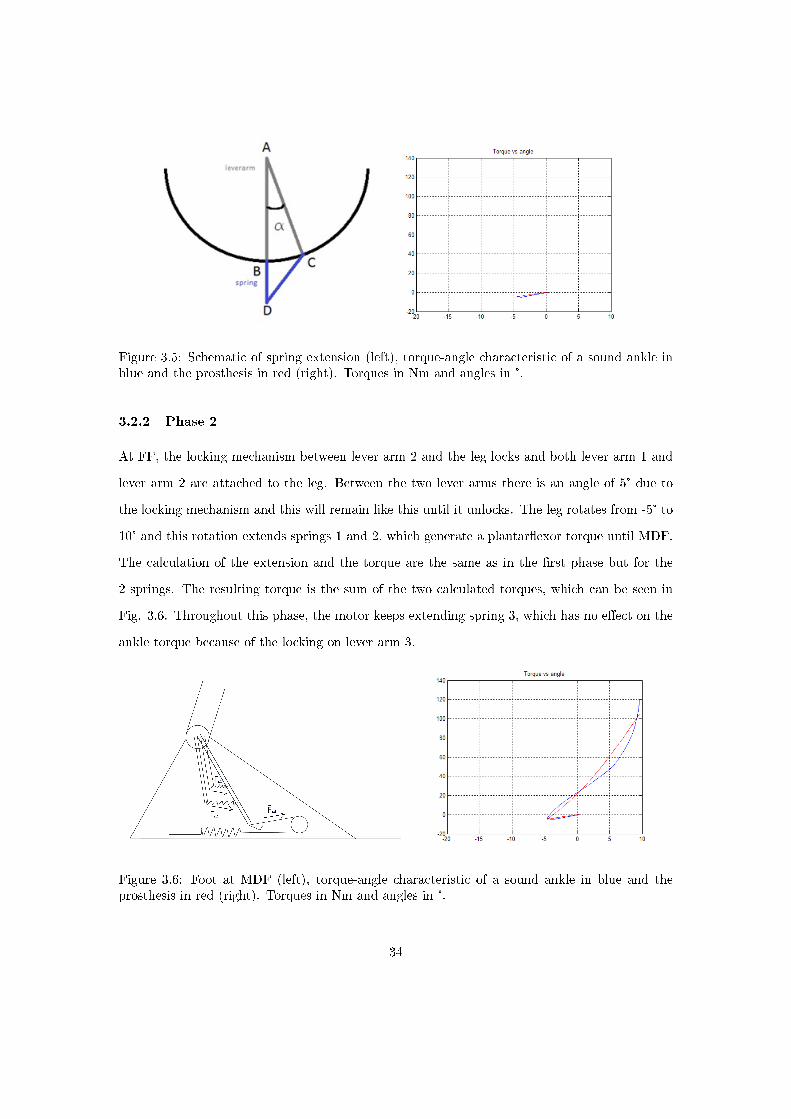
Figure 3.5: Schematic of spring extension (left), torque-angle characteristic of a sound ankle inblue and the prosthesis in red (right). Torques in Nm and angles in °.
3.2.2 Phase 2
At FF, the locking mechanism between lever arm 2 and the leg locks and both lever arm 1 and
lever arm 2 are attached to the leg. Between the two lever arms there is an angle of 5° due to
the locking mechanism and this will remain like this until it unlocks. The leg rotates from -5° to
10° and this rotation extends springs 1 and 2, which generate a plantar�exor torque until MDF.
The calculation of the extension and the torque are the same as in the �rst phase but for the
2 springs. The resulting torque is the sum of the two calculated torques, which can be seen in
Fig. 3.6. Throughout this phase, the motor keeps extending spring 3, which has no e�ect on the
ankle torque because of the locking on lever arm 3.
Figure 3.6: Foot at MDF (left), torque-angle characteristic of a sound ankle in blue and theprosthesis in red (right). Torques in Nm and angles in °.
34

3.2.3 Unlocking
At MDF, the locking mechanism that prevents the third lever arm to rotate counterclockwise
unlocks and the energy stored in spring 3 by the motor is released. Since the function of the
motor is to introduce a rise in torque at MDF, the torque generated by the elongation of spring
3 on the time of unlocking has to be higher than the one generated by the elongation of springs
1 and 2. If this is the case, the third lever arm will rotate counterclockwise to a new equilibrium
position as can be seen in Fig. 3.7.
Figure 3.7: Foot at MDF after unlocking
In order to know the resultant torque, the equilibrium position of lever arm 3 has to be
calculated. The schematic which is used to do this and the resulting torque are shown in Fig.
3.8
35

Figure 3.8: Schematic for calculation of equilibrium position (left), torque-angle characteristic ofa sound ankle in blue and the prosthesis in red (right). Torques in Nm and angles in °.
M3 = |AF × F 3| = M1+2 = |AE × F 2|+ |AC × F 1| (3.8)
WhereM3 is the torque exerted by spring 3 around point A (being the ankle joint) andM1+2
is the torque exterted by springs 1 and 2 around point A, all with notations as in Fig. 3.8.
The unknown variable in this equation is the angle of the lever arm, so the direction of AF ,
AE and AC. This equation can be solved iteratively in MATLAB by using the �fsolve� function.
With this function the di�erence between the two torques is set to zero by changing the angle
between the lever arms. Once this angle is known the extension of the spring, the resulting force
and the torque on the leg can be calculated in the same way as for phase 1 and 2:
M2 = |AD × F 2| (3.9)
3.2.4 Phase 3
After the unlocking the assisted PF starts, where all the energy that has been stored in the
springs, both by the controlled DF and the motor, is used for the PF. The ankle torque will
36

decrease until it reaches 0 Nm. The ankle torque can be calculated for all di�erent angles by
using the same method and MATLAB function as during unlocking. The motor can create an
extra extension of spring 3 during this phase. By doing this, the resting position of the system
of connected springs is changed. The goal of this is to achieve the torque of 0 Nm at an angle of
-20°, just like for a sound ankle.
Figure 3.9: Foot at TO (left), torque-angle characteristic of a sound ankle in blue and theprosthesis in red (right). Torques in Nm and angles in °.
3.2.5 Swing phase
When the ground contact is broken at TO, the locking mechanism that locks lever arm 2 will
unlock and the motor will reverse it's sense of rotation to push spring 3 back. Lever arms 1, 2
and 3 will be pulled back to their initial position by a recall spring with a low spring constant,
so that lever arm 3 can be locked again and the motor can restart extending spring 3 at IC. The
small recall spring should not in�uence the prosthesis characteristics signi�cantly
37

Figure 3.10: Foot during swing phase after locking of lever arm 3 (left), torque-angle characteristicof a sound ankle in blue and the prosthesis in red (right).
3.3 Adaptability
The ability to change the performance and the characteristics of the prosthesis without having
to change the components would be an asset. The springs are placed in such a way that the
pretensions can be changed and the motor operating speed can also be varied. In this section a
few simple experiments will indicate that changing these variables, the prosthesis can be adjusted
to the personal needs of an amputee.
3.3.1 Changing the spring pretension
The spring that is connecting the small lever arm and the large lever arm is simulated with
di�erent values of the pretension. The result is shown in Fig. 3.12. For higher pretensions, the
amount of stored energy rises as well as the torque on the ankle joint. This is logical, since a
higher pretension causes a higher ankle sti�ness. Lower pretensions cause a lower ankle sti�ness.
38
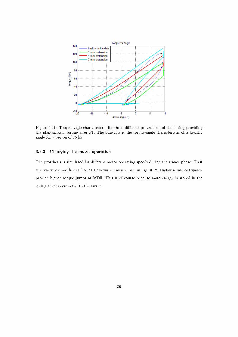
Figure 3.11: Torque-angle characteristic for three di�erent pretensions of the spring providingthe plantar�exor torque after FF. The blue line is the torque-angle characteristic of a healthyangle for a person of 75 kg.
3.3.2 Changing the motor operation
The prosthesis is simulated for di�erent motor operating speeds during the stance phase. First
the rotating speed from IC to MDF is varied, as is shown in Fig. 3.12. Higher rotational speeds
provide higher torque jumps at MDF. This is of course because more energy is stored in the
spring that is connected to the motor.
39

Figure 3.12: Torque-angle characteristic for three di�erent motor rotational speeds between ICand MDF. The blue line is the torque-angle characteristic of a healthy angle for a person of 75kg.
The prosthesis is also simulated for di�erent motor rotational speeds between MDF and TO.
The results in Fig. 3.13 show a di�erent ankle sti�ness for the assisted PF phase.
Figure 3.13: Torque-angle characteristic for three di�erent motor rotational speeds between MDFand TO. The blue line is the torque-angle characteristic of a healthy angle for a person of 75 kg.
40
3.4 Choice of components
3.4.1 Driving system
Previously the driving system of the prosthesis was always referred to as �motor�, but the problem
with a motor is that it provides a rotating movement whereas for the extension of the spring a
longitudinal movement is needed. The driving system therefore will not only consist of a motor
but also of a transmission which will transform the rotation to a translation.
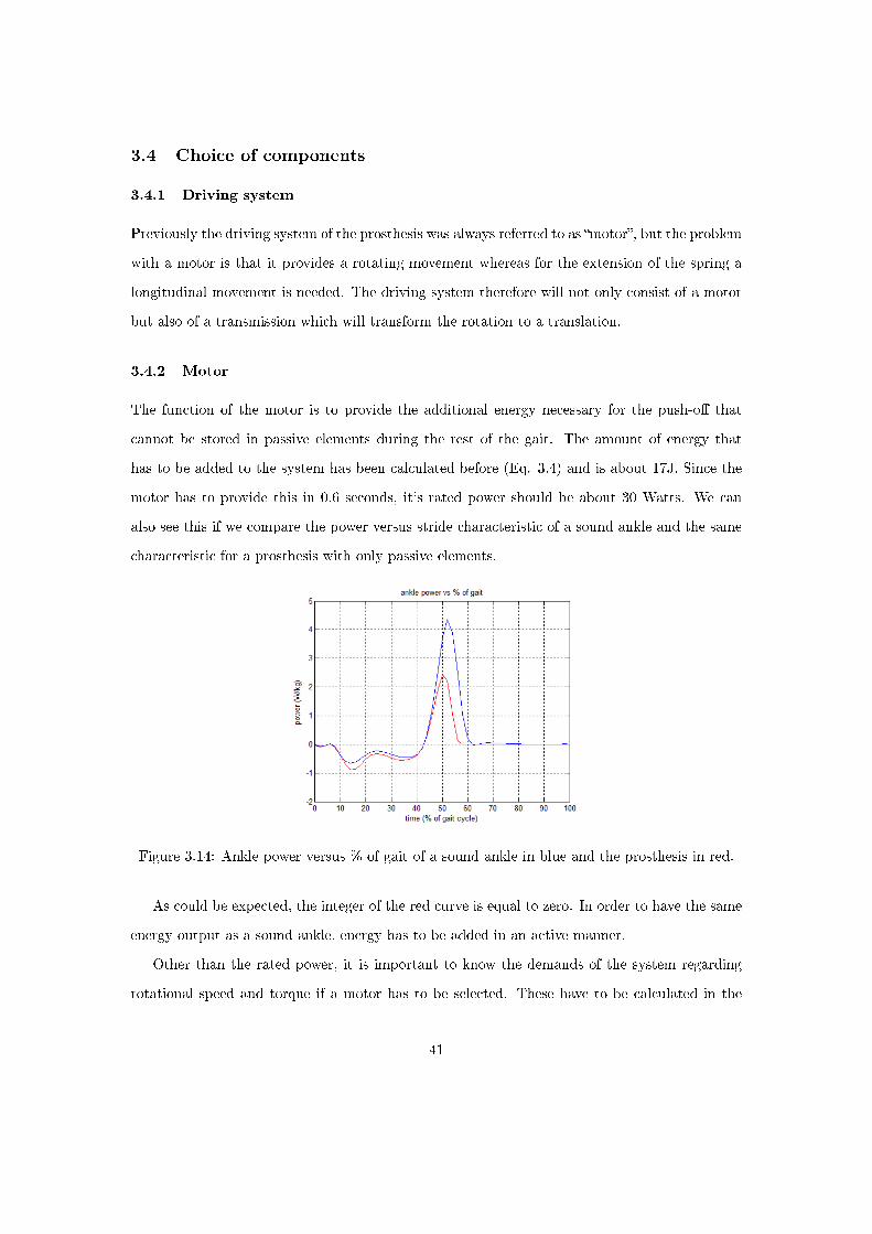
3.4.2 Motor
The function of the motor is to provide the additional energy necessary for the push-o� that
cannot be stored in passive elements during the rest of the gait. The amount of energy that
has to be added to the system has been calculated before (Eq. 3.4) and is about 17J. Since the
motor has to provide this in 0.6 seconds, it's rated power should be about 30 Watts. We can
also see this if we compare the power versus stride characteristic of a sound ankle and the same
characteristic for a prosthesis with only passive elements.
Figure 3.14: Ankle power versus % of gait of a sound ankle in blue and the prosthesis in red.
As could be expected, the integer of the red curve is equal to zero. In order to have the same
energy output as a sound ankle, energy has to be added in an active manner.
Other than the rated power, it is important to know the demands of the system regarding
rotational speed and torque if a motor has to be selected. These have to be calculated in the
41
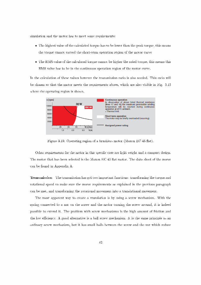
simulation and the motor has to meet some requirements:
� The highest value of the calculated torque has to be lower than the peak torque, this means
the torque cannot exceed the short-term operation region of the motor curve
� The RMS-value of the calculated torque cannot be higher the rated torque, this means this
RMS value has to be in the continuous operation region of the motor curve.
In the calculation of these values however the transmission ratio is also needed. This ratio will
be chosen so that the motor meets the requirements above, which are also visible in Fig. 3.15
where the operating region is shown.
Figure 3.15: Operating region of a brushless motor (Maxon EC 45 �at).
Other requirements for the motor in this speci�c case are light weight and a compact design.
The motor that has been selected is the Maxon EC 45 �at motor. The data sheet of the motor
can be found in Appendix A.
Transmission The transmission has got two important functions: transforming the torque and
rotational speed to make sure the motor requirements as explained in the previous paragraph
can be met, and transforming the rotational movement into a translational movement.
The most apparent way to create a translation is by using a screw mechanism. With the
spring connected to a nut on the screw and the motor turning the screw around, it is indeed
possible to extend it. The problem with screw mechanisms is the high amount of friction and
the low e�ciency. A good alternative is a ball screw mechanism. It is the same principle as an
ordinary screw mechanism, but it has small balls between the screw and the nut which reduce
42

the friction and improve the e�ciency. Whereas the e�ciency for ordinary screws is never higher
than 70%, ball screws have e�ciencies up to 95 %.
Figure 3.16: Ball screw mechanism. Image adapted from Bosch Rexroth website.
An important parameter for the selection of a ball screw mechanism is the lead, which de�nes
the transmission ratio. Every time the screw makes one complete turn, this causes a translation
of the nut over a lenght that is equal to the lead. The torque the motor has to provide can be
calculated using this length if the force necessary to extend the spring is known.
T =F × P
2× π × η(3.10)
Where T is the torque at the motor side in Nmm, F is the axial force on the nut in N, P
is the lead in mm and η is the ball screw e�ciency. For the axial force an estimate of 2400 N
will be used. If a lead of 5mm is taken (based on maximum axial load of the ball screw) and an
e�ciency of 90% :
T =2400N × 5mm
2× π × 0.9= 2.12Nm (3.11)
This is too high for the motor that was selected earlier. It is clear that an additional reduction
is necessary in order to lower the torque on the motor. A possible solution is to lower the lead,
but this would lower the maximum axial load on the ball screw and lower the e�ciency. An
other transmission has to be added to further reduce the torque on the motor. A gearbox placed
43
in between the motor and the ball screw mechanism can be used to do this. For the selected
type of motor, di�erent kinds of gearboxes are available. The most important ones are planetary
gearheads and spur gearheads. Spur gearheads are the simplest kind of gearhead. They have
two cogwheels per stage, with the �rst wheel of the �rst stage mounted on the motor shaft.
The advantage of this type is that it is cheaper than the other types, with reasonably high
e�ciencies and low noise. The disadvantage is that it is suitable for low torques only, but since
the continuous torque can go up to 2Nm this shouldn't be a problem. Planetary gearheads can
transfer higher torques but are more expensive than spur gearheads. There are other types of
gearheads that use di�erent gears like worm gears, but they are less suitable for this application
because they have a lower e�ciency due to higher friction.
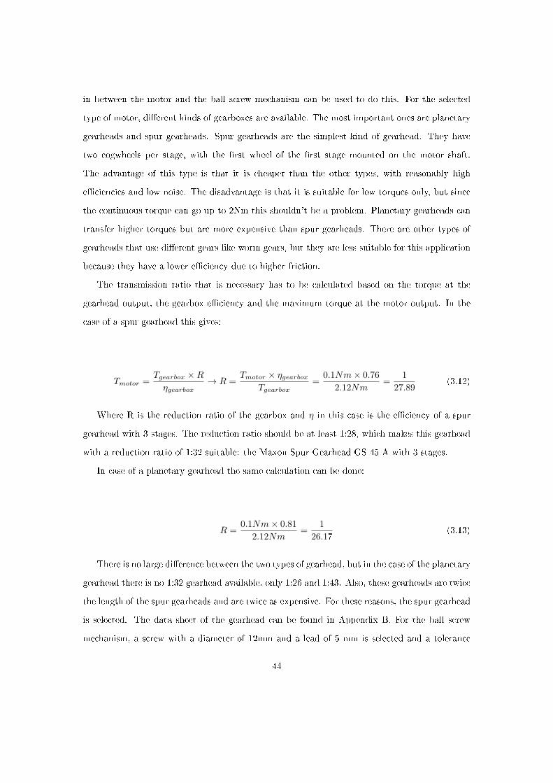
The transmission ratio that is necessary has to be calculated based on the torque at the
gearhead output, the gearbox e�ciency and the maximum torque at the motor output. In the
case of a spur gearhead this gives:
Tmotor =Tgearbox ×Rηgearbox
→ R =Tmotor × ηgearbox
Tgearbox=
0.1Nm× 0.76
2.12Nm=
1
27.89(3.12)
Where R is the reduction ratio of the gearbox and η in this case is the e�ciency of a spur
gearhead with 3 stages. The reduction ratio should be at least 1:28, which makes this gearhead
with a reduction ratio of 1:32 suitable: the Maxon Spur Gearhead GS 45 A with 3 stages.
In case of a planetary gearhead the same calculation can be done:
R =0.1Nm× 0.81
2.12Nm=
1
26.17(3.13)
There is no large di�erence between the two types of gearhead, but in the case of the planetary
gearhead there is no 1:32 gearhead available, only 1:26 and 1:43. Also, these gearheads are twice
the length of the spur gearheads and are twice as expensive. For these reasons, the spur gearhead
is selected. The data sheet of the gearhead can be found in Appendix B. For the ball screw
mechanism, a screw with a diameter of 12mm and a lead of 5 mm is selected and a tolerance
44

grade T9. The selected nut is a miniature single nut. the data sheet for both can be found in
Appendix C
Combination of motor and transmission It has to be checked wether the requirements of
the motor are met. The �rst one, highest calculated torque must be smaller than peak motor
torque, is certainly met since that was the criterium for selecting the transmission ratio. For the
second one the RMS value of the motor torque has to be calculated. First it has to be determined
how the motor will be operated. Later in the chapter about the control will be explained that
this will be with a constant speed. Because of this, the torque will rise linearly from the moment
the motor starts to work until the unlocking phase. After this, the torque will drop back to 0
Nm at TO. During the swing phase the motor will not deliver a signi�cant torque. We can put
this in a graph and calculate the RMS value.
Figure 3.17: Torque delivered by the motor in blue and RMS value of the motor torque in red.
The RMS value of 40 mNm is inside the area of continuous operation of the selected motor
so it meets both requirements. A problem with the motor however is that is should also be able
to return to its original position in time during the swing phase. As this phase is about 30%
of the gait cycle which is about 0.375 seconds and the spring is elongated over about 17 mm in
total, the necessary rotational speed can be calculated:
45

17mm
0.375s× P× 60s/min = 544rot/m (3.14)
This is normally no problem for the motor of 30 Watts since there is virtually no torque, only
the rotational speed of the motor in continuous operation is limited by the chosen transmission
ratio.
maximumspeed =10000rot/min
32= 312.5rot/min (3.15)
This means the motor has to be used at higher rotational speeds, which will cause the
components to heat up more than normally. This shouldn't be a severe problem though, because
the motor doesn't have to deliver a torque at this point. It will cause the lifespan of the motor
to drop because of a higher loading of the bearings inside the motor.
The connection of the motor to the ball screw mechanism can be done through a belt or by
directly attaching the motor shaft to the ball screw shaft. Using a belt causes additional losses
but has the advantage that the motor and gearbox don't have to be placed in line with the ball
screw mechanism. In this prosthesis however there is little space in between the foot bottom
and the ankle axis since room is reserved for the locking mechanism. Because of this reason it
is decided to place the motor and gearbox in line with the ball screw mechanism on the foot
bottom.
3.4.3 Springs
The springs in this prosthesis design must have a high spring constant, they must provide a large
force over a small extension. There are di�erent types of spring that can be used: extension
springs, compression springs, torsion springs, Belleville springs and a lot of other types. Extension
and compression springs are the most common types, but the problem with these is that they
get heavy and large with higher spring constants, and the same occurs with torsion springs.
Belleville springs can provide a lightweight alternative for this, as it is possible to create a spring
46

with a high spring constant using a small amount of material in comparison to the other types.
It is a small conical disc that has a high spring constant but only allows a small extension. By
stacking these springs, the spring constant can be modi�ed to customer needs.
Figure 3.18: Extension spring (left), compression spring (left middle), torsion spring (right mid-dle), Belleville springs (right).
The spring constants can be calculated as explained before, using the MATLAB simulation.
The choice of a spring constant is not predetermined if the pretension can be altered. Two springs
with di�erent spring constants can have a similar e�ect on the ankle. In Fig. 3.1two springs with
di�erent pretensions are compared. By using this the spring constant and the pretension can be
used to �t the sound ankle data.
Di�erent spring constants are selected and the pretension is altered in order to get a good
�t. This are the values that have been chosen:
spring 1 2 3
spring constant (N/mm) 20 200 200pretension (mm) 10 4 12
Table 3.1: Initial choice of spring constants for the three springs.
A next step is to check what types of spring are suitable to provide such a spring. For all
of the springs initially the comparison was made between extension springs, compression springs
and Belleville springs. Especially for the larger spring constants, the Belleville springs seemed
to be the best solution, but the big disadvantage of this type of springs is that they experience
a lot of friction when stacked, which causes hysteresis with the loading and unloading, and this
brings energy losses which cannot be neglected. If normal compression springs are compared
to extension springs, it can be seen that extension springs take more space than compression
47

springs. For example, if the two types are compared for a spring of 200 N/mm and an extension
of 10 mm, it is clear that the extension spring is larger than the compression spring. Dm is the
diameter of the center line of the spring wire, Fn the maximum force, L0 the neutral length and
Ln the length at maximum extension/compression.
Dm Fn L0 Ln
extension spring 40 2000 44.2 34.2compression spring 40 2000 82.3 92.3
Table 3.2: Comparison of extension and compression springs. Springs calculated at the springcalculation section of Alcomex' website: www.alcomex.nl.
A speci�c type of compression springs seems very suitable for this application. The so called
die springs are specially designed for dynamic loads and are more compact than normal com-
pression springs. Another type with similar characteristics can be found in rubber or elastomere
springs. This type however has higher spring constants for the same dimensions, which cause
the die springs to be a more compact solution.
An easy solution would be to use torsion springs on the ankle joint. Most stores that sell tor-
sion springs only o�er them with wire thicknesses up to 3 mm, with maximum torsion sti�nesses
of about 100 mNm/°, which is a factor 10 too small even for the �rst spring. The characteristics
of torsion springs can be calculated for di�erent wire thicknesses to check if the springs needed for
this application would have acceptable dimensions to �t on the ankle joint. For a given material,
wire thickness, spring constant and loading force the stress due to bending can be calculated in
the torsion spring.
σ =M
( π23 × d3)(3.16)
Where M is the torque applied and d is the wire thickness. The number of windings can also
be calculated from these variables:
n =d4 × E × α× π
360× 32×Dm×M(3.17)
Where E is the spring's material's Young modulus, α is the angle over which the spring is
rotated and Dm is the diameter of the center line of the spring wire. These values can now be
48
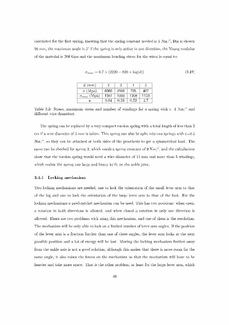
calculated for the �rst spring, knowing that the spring constant needed is 1 Nm/°, Dm is chosen
20 mm, the maximum angle is 5° if the spring is only active in one direction, the Young modulus
of the material is 206 Gpa and the maximum bending stress for the wires is equal to:
σmax = 0.7× (2220− 820× log(d)) (3.18)
d (mm) 2 3 4 5
σ (Mpa) 6366 1886 795 407σmax (Mpa) 1381 1000 1208 1153
n 0.04 0.23 0.72 1.7
Table 3.3: Stress, maximum stress and number of windings for a spring with c=1 Nm/° anddi�erent wire diameters.
The spring can be replaced by a very compact torsion spring with a total length of less than 2
cm if a wire diameter of 5 mm is taken. This spring can also be split into two springs with c=0.5
Nm/°, so they can be attached at both sides of the prosthesis to get a symmetrical load. The
same can be checked for spring 2, which needs a spring constant of 9 Nm/°, and the calculations
show that the torsion spring would need a wire diameter of 11 mm and more than 5 windings,
which makes the spring too large and heavy to �t on the ankle joint.
3.4.4 Locking mechanism
Two locking mechanisms are needed, one to lock the orientation of the small lever arm to that
of the leg and one to lock the orientation of the large lever arm to that of the foot. For the
locking mechanisms a pawl-ratchet mechanism can be used. This has two positions: when open,
a rotation in both directions is allowed, and when closed a rotation in only one direction is
allowed. There are two problems with using this mechanism, and one of them is the resolution.
The mechanism will be only able to lock on a limited number of lever arm angles. If the position
of the lever arm is a fraction further than one of these angles, the lever arm locks at the next
possible position and a lot of energy will be lost. Moving the locking mechanism further away
from the ankle axis is not a good solution, although this makes that there is more room for the
same angle, it also raises the forces on the mechanism so that the mechanism will have to be
heavier and take more space. That is the other problem, at least for the large lever arm, which
49

has to be unlocked when the forces on the locking mechanism are high. This would require a
servo motor that can overcome the high friction forces in order to unlock.
Figure 3.19: Pawl-ratchet mechanism in locked position. The ratchet can only rotate in thedirection of the arrow.
A �rst solution for the resolution problem is to provide several pawl-ratchet mechanisms for
each lever arm, each of them shifted a bit. For example if three parallel mechanisms are used,
the resolution can be up to three times as high. The placement of these mechanisms takes a lot
of room in the prosthesis since all of them have to be designed to withstand the forces too. This
is also not a good solution for the high friction at unlocking.
Another solution is to use a transmission between the lever arms and the locking mechanisms.
The advantages here are that the resolution will be higher and the forces on the locking mecha-
nism will be lower, so this solves both of the problems that occurred. A disadvantage of this is
that the friction losses in the locking mechanism will be ampli�ed on the lever arm.
A third possible solution is to use a mechanism with a singularity at the locking position.
An example of a mechanism of this kind is recently developed at the university of Twente. The
advantage of this mechanism is that it only needs a small force to unlock and there is not much
friction when the mechanism is unlocked. The disadvantage is that there is only one angle, being
the position of the singularity, where the mechanism locks. This makes it suitable for a knee
joint where 0° is where the locking happens, but for the small lever arm in the prosthesis the
locking position can vary when it is used on leveled terrain for example. The large lever arm
locking position however is not in�uenced by changes in slope of the terrain or anything else,
and this type of locking mechanism could be used for it. The problem that remains however is
that when the lever arm doesn't completely return to it's initial position, there is no locking and
so there is no additional energy for push-o� [11].
50
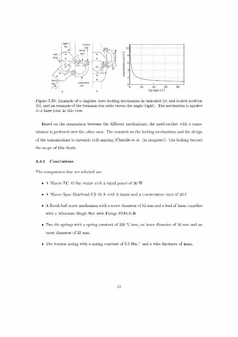
Figure 3.20: Example of a singular state locking mechanism in unlocked (a) and locked position(b), and an example of the transmission ratio versus the angle (right). The mechanism is appliedto a knee joint in this case.
Based on the comparison between the di�erent mechanisms, the pawl-ratchet with a trans-
mission is preferred over the other ones. The research on the locking mechanisms and the design
of the transmissions is currently still ongoing (Cherelle et al. (in progress)). The locking beyond
the scope of this thesis.
3.4.5 Conclusions
The components that are selected are:
� A Maxon EC 45 �at motor with a rated power of 30 W
� A Maxon Spur Gearhead GS 45 A with 3 stages and a transmission ratio of 32:1
� A Bosch ball screw mechanism with a screw diameter of 12 mm and a lead of 5mm, together
with a Miniature Single Nut with Flange FEM-E-B
� Two die springs with a spring constant of 200 N/mm, an inner diameter of 16 mm and an
outer diameter of 32 mm.
� Two torsion spring with a spring constant of 0.5 Nm/° and a wire thickness of 4mm.
51
3.5 Control and electronics
3.5.1 Sensors
Two di�erent categories of sensors can be distinct: the sensors that are necessary for the operation
of the prosthesis and those that perform measurements to check to what extend the prosthesis
performs as has been predicted by the simulations.
3.5.2 Sensors for operation
In order to make the prosthesis work as it is supposed to do, the motor and the lockings have to
be activated and deactivated at the right time. For this, sensors are needed to evaluate in which
part of the gait cycle the prosthesis is at any given time and an algorithm is needed to organise
what should happen at what time. There are 3 components that have to be controlled, being the
motor and the two locking mechanisms. To de�ne how many and which sensors are necessary,
the prosthesis operation is subdivided in di�erent phases, starting a new phase every time the
state of one of the 3 components has to change. In Table 3.4, these phases are compared with
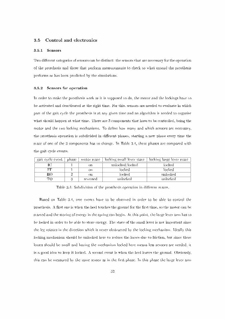
the gait cycle events.
gait cycle event phase motor state locking small lever state locking large lever state
IC 1 on unlocked/locked lockedFF 1 on locked lockedHO 2 on locked unlockedTO 3 reversed unlocked unlocked
Table 3.4: Subdivision of the prosthesis operation in di�erent states.
Based on Table 3.4, tree events have to be observed in order to be able to control the
prosthesis. A �rst one is when the heel touches the ground for the �rst time, so the motor can be
started and the storing of energy in the spring can begin. At this point, the large lever arm has to
be locked in order to be able to store energy. The state of the small lever is not important since
the leg rotates in the direction which is never obstructed by the locking mechanism. Ideally this
locking mechanism should be unlocked here to reduce the losses due to friction, but since these
losses should be small and having the mechanism locked here means less sensors are needed, it
is a good idea to keep it locked. A second event is when the heel leaves the ground. Obviously,
this can be measured by the same sensor as in the �rst phase. In this phase the large lever arm
52
is unlocked and the stored energy is released. A last sensor has to notice when the toe leaves
the ground, so that the motor can be put in reverse and the small lever can be unlocked so the
prosthesis can return to it's initial position.
There are several types of sensors that could be used to sense the ground contact. A �rst
type are force sensing resistors. These sensors give a signal when a force is applied on it's surface.
The problem with these is that their readings turned out to be unreliable on earlier prototypes,
and that they are not proof against the high forces that are applied to them when they are
attached to the foot sole [5]. Another possible sensor makes use of a contact switch to determine
whether there is contact or not. This is a simple type of sensor with a simple high or low output,
which makes it easier to interpret the readings. The problem with this type is that it is also not
resistible to high forces, so not suitable to attach to the foot sole or to let the contact switch stick
out below the foot sole. This can be solved by attaching a lever to the sensor which then pushes
the contact switch. Because the sensor lever should not stick out of the foot contour since it
might get damaged, a hinging sensor plate is attached to the heel. For the sensor that measures
the toe contact this is not necessary, because the toe joint can be used to push the sensor switch.
The sensor has to be placed in such a way that it gives a high value when the toe joint is lifted
up and a low one when it's down. The motor control than has to use the transition from high
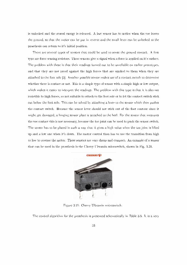
to low to reverse the motor. These sensors are very cheap and compact. An example of a sensor
that can be used in the prosthesis is the Cherry Ultramin microswitch, shown in Fig. 3.21.
Figure 3.21: Cherry Ultramin microswitch.
The control algorithm for the prosthesis is presented schematically in Table 3.5. It is a very
53

simple algorithm using only two sensors to control both of the lockings and the motor.
time (gait cycleevent)
IC MDF TO
sensor reading heel sensor high heel sensor low toe sensor high ->low
commands given motor rotatesforward, small
lever arm locked,large lever arm
locked
large lever armunlocked, motorchanges speed
motor reversed,small lever arm
unlocked
Table 3.5: Control algorithm for the prosthesis.
Sensors for measurements The prosthesis' performance has to be compared to its simulation
and to the sound ankle gait data. To be able to do this the ankle angles and torques must be
measured. Other things that can be measured to verify the performance are the lever arm locking
positions, to check if the lockings work as they are supposed to work. Measuring these things
make it easier to detect prosthesis malfunctioning and localise the problem. Because adaptations
still have to be made on the ankle joint in order to �t the locking mechanism on it, and so the
available space is unknown, these sensors couldn't be permanently chosen.
Angle measurement For the measurement of the angles a rotary encoder can be used.
There are two main types we can distinguish: absolute and relative encoders. The di�erence
between the two types is that in absolute encoders both the actual angle, changes in angle and
the direction of change can be observed, whereas relative encoders only observe changes in angles.
For the measurement of the ankle angles, it is not really necessary to have an absolute encoder.
Torque measurement The measurement of the ankle torque can be accomplished in sev-
eral ways. A �rst method is measuring the ground reaction forces. This is how the data of the
sound ankles were recorded. The problem of this method is that it requires an accurate model of
the prosthesis in which the measured forces have to be used as input to determine the torques.
If the model is not completely the same as the actual prosthesis, the torques will not be the
same as the actual torques. Another method is to measure the extension of one of the springs,
calculate the force and from that the torques. One way to do this is to measure the di�erence in
54
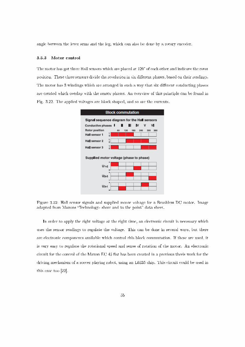
angle between the lever arms and the leg, which can also be done by a rotary encoder.
3.5.3 Motor control
The motor has got three Hall sensors which are placed at 120° of each other and indicate the rotor
position. These three sensors divide the revolution in six di�erent phases, based on their readings.
The motor has 3 windings which are arranged in such a way that six di�erent conducting phases
are created which overlap with the sensor phases. An overview of this principle can be found in
Fig. 3.22. The applied voltages are block-shaped, and so are the currents.
Figure 3.22: Hall sensor signals and supplied motor voltage for a Brushless DC motor. Imageadapted from Maxons �Technology- short and to the point� data sheet.
In order to apply the right voltage at the right time, an electronic circuit is necessary which
uses the sensor readings to regulate the voltage. This can be done in several ways, but there
are electronic components available which control this block commutation. If these are used, it
is very easy to regulate the rotational speed and sense of rotation of the motor. An electronic
circuit for the control of the Maxon EC 45 �at has been created in a previous thesis work for the
driving mechanism of a soccer playing robot, using an L6235 chip. This circuit could be used in
this case too [22].
55

Figure 3.23: Electronic circuit for the control of a brushless DC motor.
Using this circuit, the rotational speed can be changed by changing Vref and the change
of rotation is determined by the FWD/REV input. The motor torque can be calculated by
measuring the current that goes to the motor.
The motor is operated at constant speed in the simulations. For a given spring extension,
ball screw lead, gearbox transmission ratio and the available time between IC and the unlocking
of the lever arm, the necessary rotational speed and thus the necessary motor voltage can be
calculated:
ωstance1 =∆l
P × t×R× 60 =
13mm
5mm× 0.625s× 32× 60s/h = 8000rpm (3.19)
Where ωstance1 is the rotational speed during the �rst part of stance, between IC and FF, ∆l
is the extension of the spring, P is the ball screw lead, t is the time and R is the transmission
ratio of the gearbox.
The voltage can be calculated using the speed constant given in the motor data sheet.
56
Vstance1 =ω
c=
8000rpm
374rpm/V= 21.4V (3.20)
Between the unlocking of the lever arm and and TO, the spring is extended over another 4
mm in order to reach a torque of 0 Nm at an angle of -20°.
ωstance2 =3mm
5mm× 0.245s× 32× 60s/h = 4700rpm (3.21)
Vstance2 =ω
c=
6270rpm
374rpm/V= 12.6V (3.22)
For the swing phase, the same calculation can be performed.
ωswing =16mm
5mm× 0.375s× 32× 60s/h = 16400rpm (3.23)
Vswing =ω
c=
16400rpm
374rpm/V= 43.8V (3.24)
Knowing that the motor needs time to reverse its sense of rotation too, these values will have
to be slightly higher than calculated here. The mechanical time constant however is very small
(17 ms), so this will not have a large impact.
This voltage seems very high, but the motor is able to withstand a voltage larger than the
maximal voltage for continuous operation. The consequence of this is that the lifespan of the
motor will drop. Also for the L6235 chip it's not a problem since it works up to 52V. Some
measures can be taken to lower this rotational speed and voltage. ωstance2can be reduced, with
the e�ect that after powered PF, when the torque is back to 0 Nm, the angle will not be -20° but
rather to -16° or -17°. This seems to have only a very small e�ect on the gait cycle, as can be
seen in Fig. 3.24. For this result, ωstance2 was reduced to 1500 rpm, which means an extension of
1 mm rather than 3 mm. The result of this is that ωswing is reduced to 14000 rpm and Vswingto
37V. In Fig. 3.24 the torque becomes negative for angles smaller than -16, but in reality this wil
not happen. This is caused by the fact that the angles are used as an input in the simulation.
57

Figure 3.24: Result of the simulation of the prosthesis with a reduced rotating speed duringpowered PF.
3.5.4 Motor autonomy
The required amount of batteries can be calculated from the motor operation and its charac-
teristics. The torque characteristic of the motor throughout the gait is known, so from this the
current can be calculated using the torque constant that is given in the motor data sheet.
I =Tmotorc
=Tgearbox ×Rc× ηgearbox
=(F × P
2×π×ηballscrew×R
c× ηgearbox(3.25)
Where I is the motor current, Tmotor is the torque at the motor outlet shaft, c is the torque
constant of the motor, Tgearboxis the torque at the gearbox output shaft, R is the transmission
ratio of the gearbox, F is the force acting on the spring that is loaded by the motor, P is the ball
screw lead and η is the e�ciency.
It is hard to know the value of the torque during the swing phase because the forces on the
spring, F in Eq. 3.25, is around 0 here. An estimate is made of 0.001 Nm for the torque. This
torque will clearly be low in comparison to the torque during stance since there is no elongation
of springs. The motor current throughout the gait cycle is shown in Fig. 3.25.
58
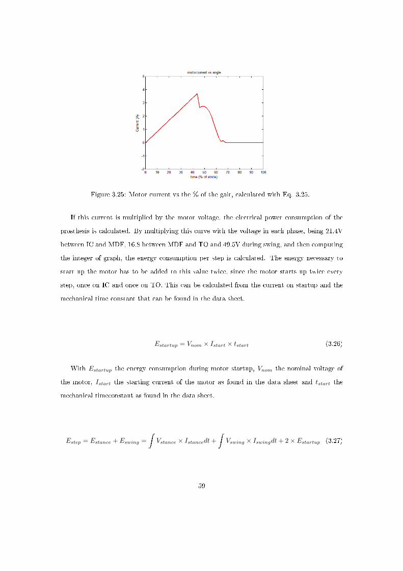
Figure 3.25: Motor current vs the % of the gait, calculated with Eq. 3.25.
If this current is multiplied by the motor voltage, the electrical power consumption of the
prosthesis is calculated. By multiplying this curve with the voltage in each phase, being 21,4V
between IC and MDF, 16.8 between MDF and TO and 49.5V during swing, and then computing
the integer of graph, the energy consumption per step is calculated. The energy necessary to
start up the motor has to be added to this value twice, since the motor starts up twice every
step, once on IC and once on TO. This can be calculated from the current on startup and the
mechanical time constant that can be found in the data sheet.
Estartup = Vnom × Istart × tstart (3.26)
With Estartup the energy consumption during motor startup, Vnom the nominal voltage of
the motor, Istart the starting current of the motor as found in the data sheet and tstart the
mechanical timeconstant as found in the data sheet.
Estep = Estance + Eswing =
�Vstance × Istancedt+
�Vswing × Iswingdt+ 2× Estartup (3.27)
59
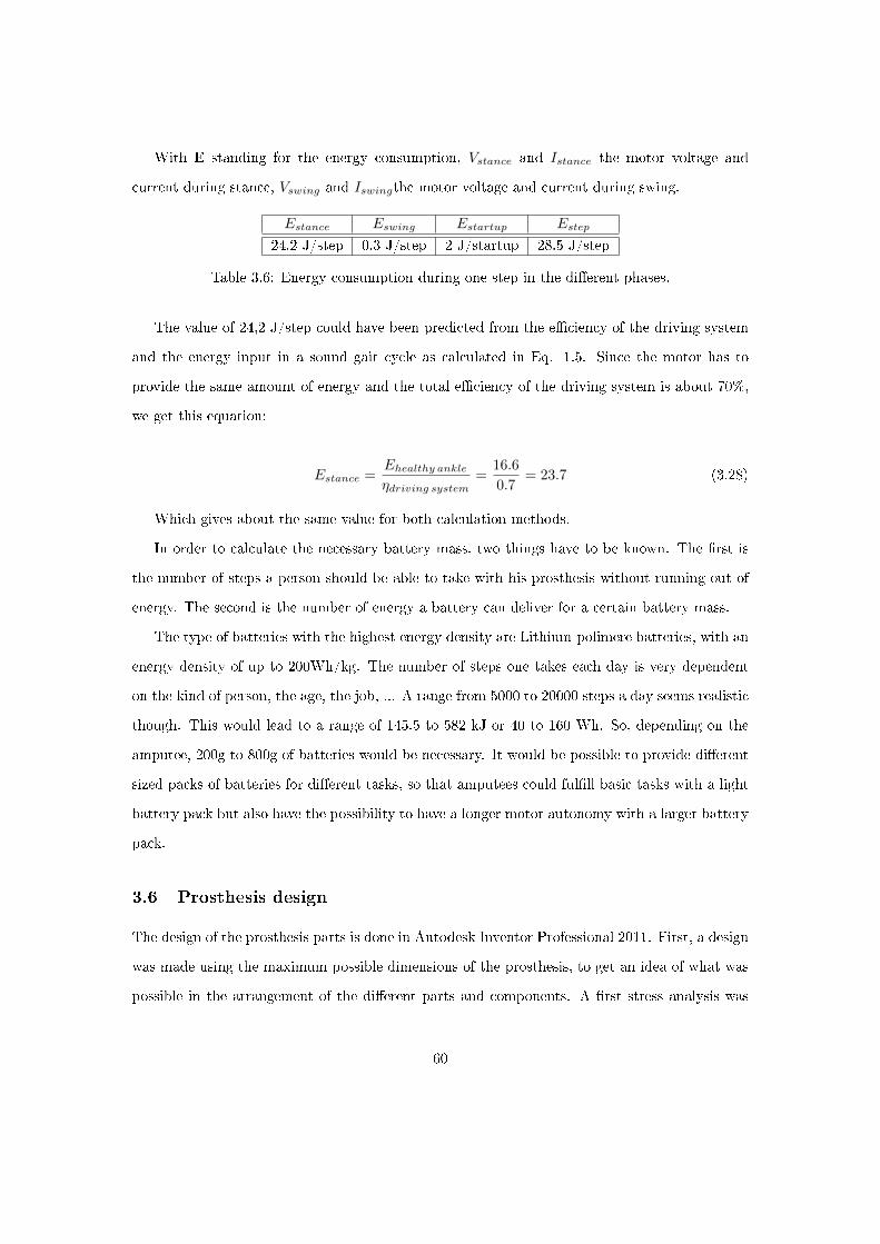
With E standing for the energy consumption, Vstance and Istance the motor voltage and
current during stance, Vswing and Iswingthe motor voltage and current during swing.
Estance Eswing Estartup Estep
24.2 J/step 0.3 J/step 2 J/startup 28.5 J/step
Table 3.6: Energy consumption during one step in the di�erent phases.
The value of 24,2 J/step could have been predicted from the e�ciency of the driving system
and the energy input in a sound gait cycle as calculated in Eq. 1.5. Since the motor has to
provide the same amount of energy and the total e�ciency of the driving system is about 70%,
we get this equation:
Estance =Ehealthy ankleηdriving system
=16.6
0.7= 23.7 (3.28)
Which gives about the same value for both calculation methods.
In order to calculate the necessary battery mass, two things have to be known. The �rst is
the number of steps a person should be able to take with his prosthesis without running out of
energy. The second is the number of energy a battery can deliver for a certain battery mass.
The type of batteries with the highest energy density are Lithium-polimere batteries, with an
energy density of up to 200Wh/kg. The number of steps one takes each day is very dependent
on the kind of person, the age, the job, ... A range from 5000 to 20000 steps a day seems realistic
though. This would lead to a range of 145.5 to 582 kJ or 40 to 160 Wh. So, depending on the
amputee, 200g to 800g of batteries would be necessary. It would be possible to provide di�erent
sized packs of batteries for di�erent tasks, so that amputees could ful�ll basic tasks with a light
battery pack but also have the possibility to have a longer motor autonomy with a larger battery
pack.
3.6 Prosthesis design
The design of the prosthesis parts is done in Autodesk Inventor Professional 2011. First, a design
was made using the maximum possible dimensions of the prosthesis, to get an idea of what was
possible in the arrangement of the di�erent parts and components. A �rst stress analysis was
60
performed on the parts to roughly know the necessary dimension to withstand the forces. Then
the arrangement that would be as compact as possible was chosen and the parts were designed
to use less material and �t in the prosthesis. Di�erent variables in the prosthesis simulation, like
the spring sti�nesses and pretensions, lengths of the lever arms and spring connection points,
were varied in order to optimise the design without a�ecting the prosthesis' characteristics.
3.6.1 Initial design phase
In the �rst phase of the design, some di�erent arrangements were tried out. The design started
by creating a foot structure with dimensions as large as acceptable: a heigth of 90 mm to the
ankle joint, a width of 100 mm and a length of about 250 mm. This is an estimation, based on
the dimensions of a sound foot. Several di�culties that had to be solved became clear during
this phase:
� The motor and gearbox, in line with the ball screw mechanism would have to �t on the
foot sole together with the two die springs, which have an outer diameter of 32 mm and
a length of about 38 mm. Since the motor has a diameter of 45 mm, placing the springs
next to the motor would almost cause the whole 100 mm of available space in the width of
the prosthesis to be taken. This would clearly not lead to a compact design.
� The springs have to be attached to the lever arms or the ball screw nut. Since the springs
should be loaded symmetrically and not under an angle, this requires a lot of pulley mech-
anisms or, ideally, the springs to be placed in such a way that few pulleys as needed, so in
line with the lever arm or ball screw.
� The lever arms that are connected to each other should also be loaded as symmetrically as
possible to avoid out of plane deformation.
� The deformation of the foot bottom plate has to be as small as possible, since the tolerance
on radial displacement for the ball screw mechanism is very small.
� Allowing an inversion and eversion movement in the prosthesis, which would bring the
prosthesis behaviour closer to that of a healthy angle, is very hard with this concept. Nor-
mally this rotation happens in between the ankle joint and the foot bottom, and allowing
61
this would cause lever arms and motor axis to collide. There are other options to provide
this movement. A �rst one is to allow a rotation in the frontal plane above the ankle joint
by adding a second joint with a narrow range of rotation. A second one is to attach a
rubber strip at the bottom of the prosthesis. Both of these could allow a small change in
angle in the frontal plane.
� The locking mechanisms for both of the lever arms would be placed on the ankle axis. After
considering the possible options, the prosthesis was made less wide at the ankle joint so
that the locking mechanisms could be placed on both sides of the prosthesis, on the outside
of the foot connected to the ankle axis.
3.6.2 Final design
The di�erent parts of the prosthesis will now be described as will the results of a stress analysis.
For a better understanding of the design motivations, �rst the design and the arrangement of
the parts will be described and the stress analysis will be done afterwards.
Final arrangement The motor and gearbox, in line with the ball screw assembly are placed
in the center of the prosthesis on the foot bottom plate. The side of the prosthesis is made of
two sagittal structures which support the ankle axis as can be seen in Fig. 3.26.
62

Figure 3.26: The foot sagittal and bottom structure, with the motor and gearbox at the backand the ball screw assembly with the screw, nut and two pillow blocks.
The gearbox is attached to the foot bottom by means of a structure which is connected both
to the gearbox and the foot bottom with bolts. The motor axis is connected to the ball screw
axis and the spring that is elongated by the motor is placed over this connection. Both sides of
this spring are connected to cables, one side to be connected to the ball screw nut, the other side
to be connected to the large lever arm. The spring is placed over an axis which has to prevent it
from moving and hitting the motor or ball screw axis when compressed (Fig. 3.27). The axis is
connected to the gearbox connecting structure on one side and to the ball screw bearing on the
other side.
63

Figure 3.27: The spring that is placed over the motor-ball screw connection.
A structure is connected to the ball screw nut that allows to connect a wire from the nut to
the spring. This wire can be directly connected to the spring, without the need for pulleys (Fig.
3.28).
64

Figure 3.28: The prosthesis structure with the driving system and one of the springs.
On the ankle axis the two lever arms are connected. The large lever arm is placed in the
center. The end of the lever arm is split in two parts to �t around the ball screw assembly, and
to be able to load the spring symmetrically. The small lever is split into two parts, one on each
side of the large lever, again to have a symmetrical load and to avoid out of plane deformation
(Fig. 3.29).
65

Figure 3.29: The two lever arms, connected to the ankle axis and placed over the driving systemaxis.
The large lever cannot be directly connected to the spring, because the forces would be acting
in the wrong direction. Pulleys are placed on each side of the center to connect the lever to the
spring in a correct way (Fig. 3.30).
66

Figure 3.30: The pulleys attached to the side structure of the prosthesis.
The spring for the controlled DF is placed on the small lever arm, on the back side of the
prosthesis. The end of the spring is connected with the steel wires that go over the ankle axis
and connect the small lever to the large lever. The torsion springs are placed on the ankle axis
and connected to the leg and the large lever arm (Fig. 3.31).
67

Figure 3.31: One of the springs, attached to the small lever arm and placed at the back of theprosthesis, and two torsion springs placed on the ankle axis.
Finally, a toe joint is connected to the front of the prosthesis and the heel sensor plate is
connected to the back (Fig. 3.32).
68
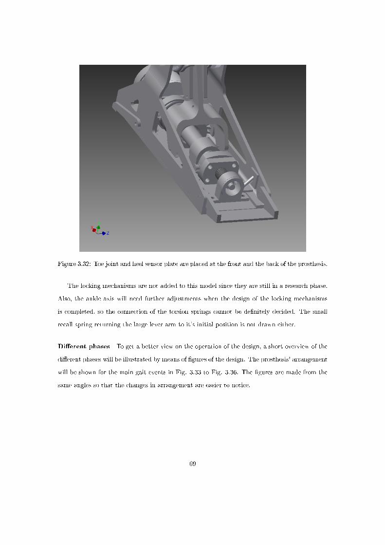
Figure 3.32: Toe joint and heel sensor plate are placed at the front and the back of the prosthesis.
The locking mechanisms are not added to this model since they are still in a research phase.
Also, the ankle axis will need further adjustments when the design of the locking mechanisms
is completed, so the connection of the torsion springs cannot be de�nitely decided. The small
recall spring returning the large lever arm to it's initial position is not drawn either.
Di�erent phases To get a better view on the operation of the design, a short overview of the
di�erent phases will be illustrated by means of �gures of the design. The prosthesis' arrangement
will be shown for the main gait events in Fig. 3.33 to Fig. 3.36. The �gures are made from the
same angles so that the changes in arrangement are easier to notice.
69
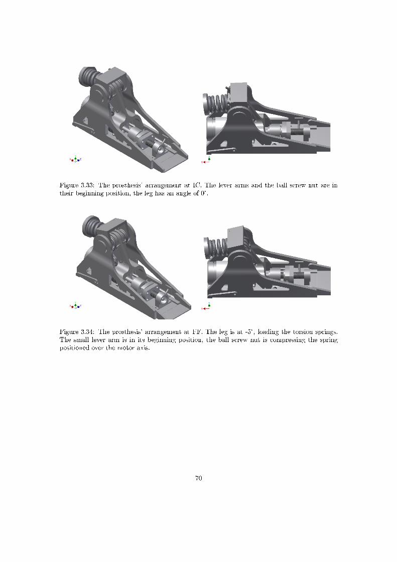
Figure 3.33: The prosthesis' arrangement at IC. The lever arms and the ball screw nut are intheir beginning position, the leg has an angle of 0°.
Figure 3.34: The prosthesis' arrangement at FF. The leg is at -5°, loading the torsion springs.The small lever arm is in its beginning position, the ball screw nut is compressing the springpositioned over the motor axis.
70
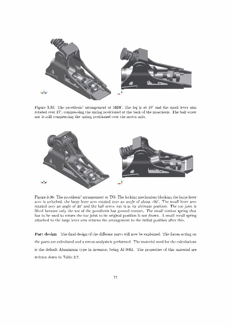
Figure 3.35: The prosthesis' arrangement at MDF. The leg is at 10° and the small lever armrotated over 15°, compressing the spring positioned at the back of the prosthesis. The ball screwnut is still compressing the spring positioned over the motor axis.
Figure 3.36: The prosthesis' arrangement at TO. The locking mechanism blocking the large leverarm is unlocked, the large lever arm rotated over an angle of about -20°. The small lever armrotated over an angle of 30° and the ball screw nut is at its ultimate position. The toe joint islifted because only the toe of the prosthesis has ground contact. The small torsion spring thathas to be used to return the toe joint to its original position is not drawn. A small recall springattached to the large lever arm returns the arrangement to the initial position after this.
Part design The �nal design of the di�erent parts will now be explained. The forces acting on
the parts are calculated and a stress analysis is performed. The material used for the calculations
is the default Aluminium type in inventor, being Al 6061. The properties of this material are
written down in Table 3.7.
71

property mass density yield strength ultimate tensile strength
value 2.71 g/cm^3 275 MPa 310 MPa
Table 3.7: Properties of Al 6061 (Autodesk Inventor database).
For all of the parts, the stress calculations are done with the highest loads that occur. The
safety factor is de�ned as the maximum stress divided by the yield strenght. The calculations are
�rst done for a static load, afterwards an extra safety factor is applied if the loads are dynamic,
which is the case for most of the parts. The extra safety factor depends on maximum stress limit
for an in�nite number of loading cycles when fatigue occurs. This maximum stress is di�erent for
di�erent loading conditions. Table 3.8 gives the stress limit and the safety factor for the di�erent
loading conditions for Al 6061.
loadingconditions
static (Yieldstrength)
Bending fatigue Axial fatigue Torsion fatigue
Maximumstrenght (MPa)
260 232.5 216 154
safety factor 1 0.89 0.83 0.59
Table 3.8: Additional safety factors for di�erent dynamic loading conditions.
Large lever arm The large lever is connected to the ankle axis under an angle of 30° when
locked. There are two loading conditions that are looked at, one just before unlocking, when
the forces on the bottom connection point, connected to the motor loaded spring, are maximal,
and just after unlocking, when the forces on the top connection point, connected to the small
lever arm, are maximal. The maximum force due to the motor loaded spring is 2600 N. At this
point, the forces between the small lever arm and the large lever arm are 2326 N. These values
are calculated in the prosthesis simulation. Also, the angles of the forces can be calculated there,
but for this case the forces can be approximated with forces in the transverse plane. It can be
seen in the simulation that this is a good approximation, for example the 2600 N is really 2584
N in the transverse plane and 290 N perpendicular to this plane. This last force only has a small
e�ect on the lever arm.
72
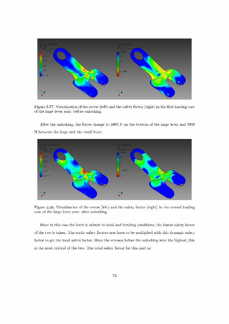
Figure 3.37: Visualisation of the stress (left) and the safety factor (right) in the �rst loading caseof the large lever arm: before unlocking.
After the unlocking, the forces change to 1680 N on the bottom of the large lever and 2800
N between the large and the small lever.
Figure 3.38: Visualisation of the stress (left) and the safety factor (right) in the second loadingcase of the large lever arm: after unlocking.
Since in this case the lever is submit to axial and bending conditions, the lowest safety factor
of the two is taken. The static safety factors now have to be multiplied with this dynamic safety
factor to get the total safety factor. Since the stresses before the unlocking were the highest, this
is the most critical of the two. The total safety factor for this part is:
73
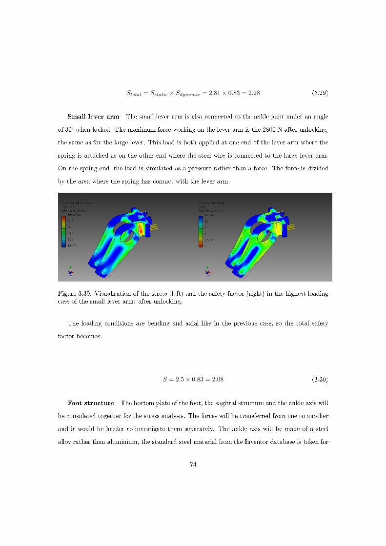
Stotal = Sstatic × Sdynamic = 2.81× 0.83 = 2.28 (3.29)
Small lever arm The small lever arm is also connected to the ankle joint under an angle
of 30° when locked. The maximum force working on the lever arm is the 2800 N after unlocking,
the same as for the large lever. This load is both applied at one end of the lever arm where the
spring is attached as on the other end where the steel wire is connected to the large lever arm.
On the spring end, the load is simulated as a pressure rather than a force. The force is divided
by the area where the spring has contact with the lever arm.
Figure 3.39: Visualisation of the stress (left) and the safety factor (right) in the highest loadingcase of the small lever arm: after unlocking.
The loading conditions are bending and axial like in the previous case, so the total safety
factor becomes:
S = 2.5× 0.83 = 2.08 (3.30)
Foot structure The bottom plate of the foot, the sagittal structure and the ankle axis will
be considered together for the stress analysis. The forces will be transferred from one to another
and it would be harder to investigate them separately. The ankle axis will be made of a steel
alloy rather than aluminium, the standard steel material from the Inventor database is taken for
74

this (Yield strenght = 207 MPa). The forces acting on the foot bottom can be derived from the
ground reaction force vector diagram that has been introduced before. This diagram shows the
forces acting on the ground. We also know that these forces act at the back end of the prosthesis
in the beginning of the stance and at the front end at the end of the stance.
Figure 3.40: Ground reaction force vector diagram. See the chapter about biomechanics for moreexplanation.
Not all of these forces will be inserted in the Inventor simulation, but some load cases will be
applied, representing the highest acting loads. These will be the loads at IC and at TO, when
the forces act on the most extreme points of the prosthesis but only about 60% of the body
weight is applied, the highest points in the force vector diagram, where about 120% of the body
weight is applied. For a person of 75 kg, the body weight will be 750 N. The forces will not only
be acting on the foot bottom plate but also on the ankle axis.
Other loads that are working on these parts are the forces on the ball screw bearings and the
pulleys, and the force that the lever arms exert on the axis. These forces depend on how much
the spring that is connected to the ball screw is elongated. The maximum value of this force is
2600 N. This force would induce a high amount of stress in the foot bottom plate if the pulleys
would be attached there. To avoid this, the pulleys are connected to the sagittal structure of
the foot and the connection plate is made large enough so that the forces are spread out over a
larger area. The forces exerted by the lever arms are di�erent before and after unlocking. When
a lever arm is locked, a torque load is applied on the axis since the rotation is stopped by the
locking mechanism. At the same time, the force that is applied on the lever arm by the springs
is also applied on the axis, causing bending of the axis. When unlocked, there is no torque on
75

the axis and also the force causing bending will be small. The maximum torque applying is
200 Nm, just before unlocking, and the maximum force on the axis can be calculated from the
positions of the lever arms just before unlocking. The calculation for the forces on the small
lever is explained in Fig. 3.41, the forces on the large lever will be small compared to this force
since the forces exerted by the ball screw will always be accompanied with a force in the opposite
direction exerted by the small lever.
Figure 3.41: Force on the prosthesis axis due to the small lever. The two vectors of 2800 N arethe forces due to the spring attached to the lever arm. 4850 N is the resultant force on the ankleaxis.
For the analysis the ankle joint hole in the sagittal structure of the foot is set �xed. The
problem with this is that the extra forces on the ankle due to the small lever arm is not included
in the analysis since it is �carried� by the �xed constraint. For this reason, in a second analysis
the bottom plate is constraint and the forces on the ankle joint are looked at. Ideally these are
looked at together but a stress analysis always requires one part of the structure to be constraint.
The forces due to the lever arm are only considered in the third load case, since they are the
largest there.
76
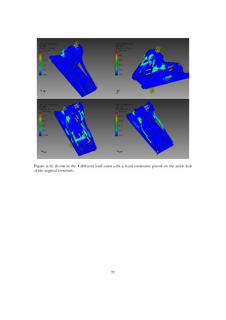
Figure 3.42: Stress in the 4 di�erent load cases with a �xed constraint placed on the ankle holeof the sagittal structure.
77
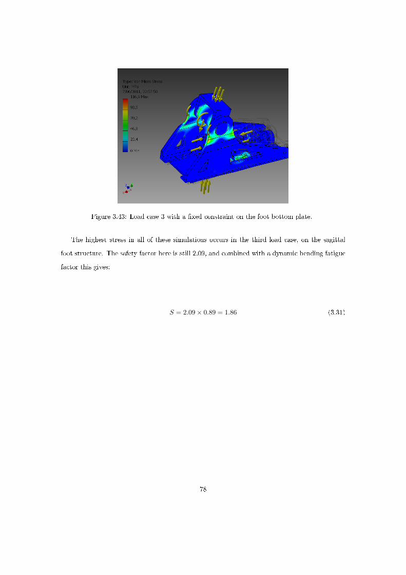
Figure 3.43: Load case 3 with a �xed constraint on the foot bottom plate.
The highest stress in all of these simulations occurs in the third load case, on the sagittal
foot structure. The safety factor here is still 2.09, and combined with a dynamic bending fatigue
factor this gives:
S = 2.09× 0.89 = 1.86 (3.31)
78

Figure 3.44: Displacement in the prosthesis for the third load case.
As can be noticed in the simulation report above, the displacement of the foot bottom plate
is rather high if it is compared to the maximum radial displacement of the ball screw axis, being
0.022 mm. This can be calculated from the following formula from the ball screw data sheet:
ep =lu
300mm× v300p =
50mm
300mm× 130µm = 0.022mm (3.32)
Where e_{p} is the permissible travel deviation, so the permissible radial displacement of
one end of the ball screw compared to the other end, l_{u} is the useful travel length of the ball
screw and v_{300p} is the permissible travel deviation within 300 mm travel, which is given in
the data sheet. It is very hard to achieve a displacement of the foot bottom that is this low, the
only way to do this would be to increase the thicknesses of the side structure and the bottom
plate of the prosthesis. This would not be a good solution and would not lead to a compact an
light design. A solution to this problem is to use a �exible coupling between the motor and the
ball screw axes and use self-aligning bearings for the ball screw. This way, the displacement of
the foot bottom plate is allowed to be a lot higher without obstructing the ball screw operation.
For the bearing the closest to the motor, for which the axial load is the highest, a spherical plain
bearing (SKF GE 8 C) is selected since these are compact and are resistant to large axial loads.
79
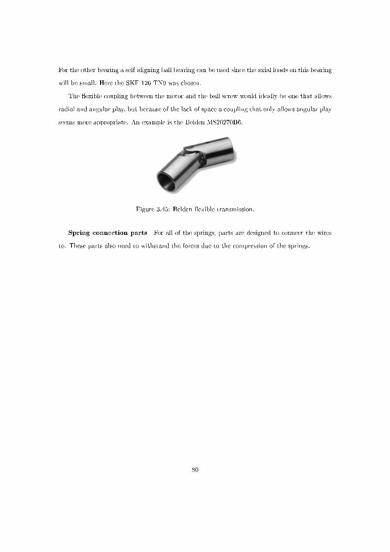
For the other bearing a self-aligning ball bearing can be used since the axial loads on this bearing
will be small. Here the SKF 126 TN9 was chosen.
The �exible coupling between the motor and the ball screw would ideally be one that allows
radial and angular play, but because of the lack of space a coupling that only allows angular play
seems more appropriate. An example is the Belden MS20270B6.
Figure 3.45: Belden �exible transmission.
Spring connection parts For all of the springs, parts are designed to connect the wires
to. These parts also need to withstand the forces due to the compression of the springs.
80

Figure 3.46: Parts made for the connection of wires to the springs and to the ball screw nut.
The minimum safety factor for these three parts is 1,99. Combined with a dynamic bending
fatigue factor this gives:
S = 1.99× 0.89 = 1.77 (3.33)
Prosthesis mass The mass of every part of the prosthesis can be calculated from the inventor
model, other masses can be estimated or read in data sheets. The approximate masses are written
down in Table 3.9.
81
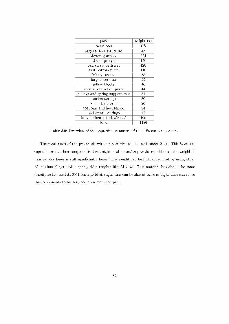
part weight (g)ankle axis 270
sagittal foot structure 262Maxon gearhead 2242 die springs 150
ball screw with nut 120foot bottom plate 116Maxon motor 88large lever arm 59pillow blocks 46
spring connection parts 44pulleys and spring support axis 31
torsion springs 30small lever arm 26
toe joint and heel sensor 24ball screw bearings 17
bolts, others (steel wire,...) 100total 1486
Table 3.9: Overview of the approximate masses of the di�erent components.
The total mass of the prosthesis without batteries will be well under 2 kg. This is an ac-
ceptable result when compared to the weight of other active prostheses, although the weight of
passive prostheses is still signi�cantly lower. The weight can be further reduced by using other
Aluminium-alloys with higher yield strenghts like Al 7075. This material has about the same
density as the used Al 6061 but a yield strenght that can be almost twice as high. This can cause
the components to be designed even more compact.
82
4 General conclusions and future work
The goal of this thesis was to investigate the possibility of storing energy in one part of the
gait cycle and releasing it when necessary to provide push-o�. A prosthesis had to be simulated
and designed that could mimick the behaviour of a sound ankle, providing enough energy to
experience push-o�. This energy was to be stored in a spring by a small motor during the rest
of the gait cycle.
In a �rst stage, the human gait cycle was examined and an extensive description was made.
This was important to identify the conditions the prosthesis had to meet and the tools that
could be used to check the similarity between prosthesis and healthy ankle. A simulation was
made to provide the data which could be used for the comparison with healthy ankle data. The
simulation was also used to optimise the choice for the di�erent components. The components
that were chosen are a 30 W Maxon EC 45 �at motor, a Maxon Spur Gearhead GS 45 A with
a transmission ratio of 1:32, a Bosch Rexroth ball screw mechanism with a lead of 5mm, 2 die
springs with a spring constant of 200 N/mm and two small torsion springs with a spring constant
of 500 Nmm/°.
A design was gradually developed in order to achieve a compact and light yet su�ciently
strong prosthesis. It is capable of providing the necessary energy at the right time and above
all the characteristics of the prosthesis can be �ne-tuned to �t the needs of any amputee within
certain boundaries. These boundaries are for example a maximum weight and maximum walking
speed of the amputee, and they depend on the motor characteristics safety factors of the design.
For people with a higher mass than the 75 kg that has been used for the dimensioning of the
prosthesis, a driving system with a higher power is needed. A Maxon �at motor of 50 W is
available which has about the same dimensions as the 30W motor that has been chosen. It
should be possible to �t this motor, together with a gearbox with a smaller transmission ratio,
in the prosthesis without problems.
The simulations and the design have shown that working principle of storing energy in one
part of the gait cycle and releasing it in another part works and can be a good base to develop
other concepts of energy storage. The drawback of this working principle is the complicated
mechanical structure with the locking mechanisms and lever arms that have to be connected to
83
the moving springs. Passive ankle prosthesis concepts or concepts where energy from the knee
joint is used to provide push-o� still have to be further developed.
It is very likely that further improvements and corrections can be made to the prosthesis
design. Especially when the the design of the locking mechanisms will be completed, changes
will have to be made to the design. In the process of the design, it was always kept in mind
that these lockings still had to be implemented, so the changes should not be extremely di�cult
to make, although it was not easy designing when an important part of the system was still a
blackbox.
84

References
[1] A. P. Arya, A. Lees, H. C. Nerula, and L. Klenerman. A biomechanical comparison ofthe sach, seattle and jaipur feet using ground reaction forces. Prosthetics and OrthoticsInternational, 19(1):37�45, 1995.
[2] S. Au, M. Berniker, and H. Herr. Powered ankle-foot prosthesis to assist level-ground andstair-descent gaits. Neural Networks, 21(4):654 � 666, 2008. Robotics and Neuroscience.
[3] S. K. Au, H. Herr, J. Weber, and E. C. Martinez-Villalpando. Powered ankle-foot prosthesisfor the improvement of amputee ambulation. Conference Proceedings of the InternationalConference of IEEE Engineering in Medicine and Biology Society, 2007:3020�3026, 2007.
[4] R. Bellman, M. Holgate, and T. Sugar. Sparky 3: Design of an active robotic ankle pros-thesis with two actuated degrees of freedom using regenerative kinetics. In Proceedings ofthe 2nd Biennial IEEE/RAS-EMBS International Conference on Biomedical Robotics andBiomechatronics., 2008.
[5] B. Brackx. Reverse engineering and redesign of a passive below-knee prosthesis prototype.Master's thesis, Vrije Universiteit Brussel, 2010.
[6] S. H. Collins and A. D. Kuo. Recycling energy to restore impaired ankle function duringhuman walking. PLoS ONE, 5(2):e9307, 02 2010.
[7] B. Hannaford G. K. Klute, J. M. Czerniecki. Muscle-like pneumatic actuators for below-kneeprostheses. In Actuator 2000: 7th International Conference on New Actuators, 2000.
[8] J. C. H. Goh, S. E. Solomonidis, W. D. Spence, and J. P. Paul. Biomechanical evaluationof sach and uniaxial feet. Prosthetics and Orthotics International, 8(3):147�154, 1984.
[9] B. J. Hafner, J. E. Sanders, J. M. Czerniecki, and J. Fergason. Transtibial energy-storage-and-return prosthetic devices: a review of energy concepts and a proposed nomenclature.Journal Of Rehabilitation Research And Development, 39:1�11, 2002.
[10] J. K. Hitt, R. Bellman, M. Holgate, T. G. Sugar, and K. W. Hollander. The sparky (springankle with regenerative kinetics) project: Design and analysis of a robotic transtibial pros-thesis with regenerative kinetics. ASME Conference Proceedings, 2007(4806X):1587�1596,2007.
[11] J. Perry. Gait Analysis: Normal and Pathological Function. Delmar Learning, 1st edition,January 1992.
[12] G. A. Pratt, Daniel E, Force Feedback Control Of Manipulator, Fine Motions, J. Dyn, andSyst Measurement Contr. Series elastic actuators. 1995.
[13] J. Pratt, B. Krupp, and C. Morse. Series elastic actuators for high �delity force control.International Journal of Industrial Robotics, 29(3):234�241, 2002.
[14] A. Tehrani and M. Vermeire. Design of a below-knee prosthesis powered by electric drives.Master's thesis, Vrije Universiteit Brussel, 2008.
[15] W. A. R. Thomson and J. D. Comrie. Black's medical dictionary / by William A. R.Thomson. Black, London :, 28th ed. edition, 1968.
85

[16] G. van Oort, R. Carloni, D. J. Borgerink, and S. Stramigioli. An energy e�cient knee lockingmechanism for a dynamically walking robot. In IEEE International Conference on Roboticsand Automation, ICRA 2011, USA, May 2011. IEEE Robotics and Automation Society.
[17] R. Versluys. Study and Development of Articulated Ankle Prostheses with Adaptable Com-pliance and Push-o� Properties. PhD thesis, Vrije Universiteit Brussel, 2009.
[18] R. Versluys, A. Desomer, G. Lenaerts, O. Pareit, B. Vanderborght, G. Van der Perre,L. Peeraer, and D. Lefeber. A biomechatronical transtibial prosthesis powered by pleatedpneumatic arti�cial muscles. International Journal of Modelling, Identi�cation and Control,4(4):394�405, 2008.
[19] M. Whittle. Gait analysis: an introduction. Elsevier, 3 edition, 2002.
[20] M. M. Williamson. Series elastic actuators. NASA STI/Recon Technical Report N, 96:17284�+, January 1995.
[21] D. A. Winter. Biomechanics and Motor Control of Human Gait: Normal, Elderly andPathological. Waterloo Biomechanics, 2 edition, December 1991.
[22] J. De Witte. Mechatronic design of a soccer robot for the small-size league of robocup.Master's thesis, Vrije Universiteit Brussel, 2010.
86
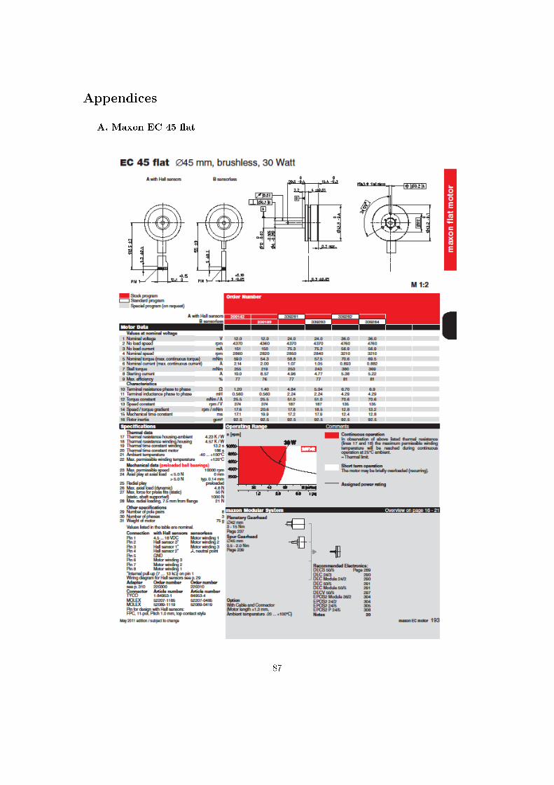
Appendices
A. Maxon EC 45 �at
87
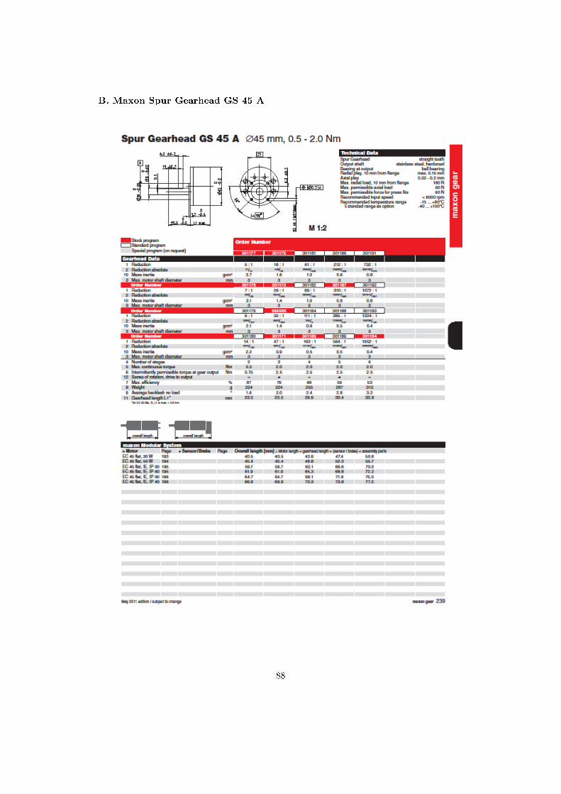
B. Maxon Spur Gearhead GS 45 A
88

C. Bosch Rexroth Miniature Nut and screw
89

90
Related Documents