Thermostatic Control Valve Model B www.amot.com Datasheet B Thermostatic Control Valve 0119rev15 Page 1 Typical applications • Lubricating oil temperature control • Jacket water high temperature (HT) • Secondary water low temperature (LT) • Heat recovery • Water saving applications • Boiler inlet temperature control • Co-generation, cooling towers • Temperature mixing or diverting • Engine and compressor cooling system Key benefits • No external power source required - Simple, low cost installation • No user setting needed - ‘Fit and forget’ solution • Small number of parts - Simple maintenance and low cost of ownership • Robust design capable of high vibration and shock applications • Easy installation, operates in any mounting position • Automatic self-sensing control with positive proportional valve action Key features • Flow rates of 15 - 400 m 3 /hr (68 - 1750 US gpm) • Combinations available: - Housings in cast iron, ductile iron, bronze, carbon steel, stainless steel • DN40 - DN200 (1 ½” - 8”) pipe sizes • Threaded and flanged connections • Tamper-proof temperature settings from 13°C - 116°C (55°F - 240°F) • Pressure ratings up to 45 bar (655 psi) Model B Accreditations available • PED Suitable for Group 1 & 2 liquids (Ensure materials are compatible) • ATEX II 2G TX X • Complies with all relevant EU directives

Welcome message from author
This document is posted to help you gain knowledge. Please leave a comment to let me know what you think about it! Share it to your friends and learn new things together.
Transcript
Thermostatic Control ValveModel B
www.amot.com
Datasheet B Thermostatic Control Valve 0119rev15 Page 1
Typical applications• Lubricating oil temperature control
• Jacket water high temperature (HT)
• Secondary water low temperature (LT)
• Heat recovery
• Water saving applications
• Boiler inlet temperature control
• Co-generation, cooling towers
• Temperature mixing or diverting
• Engine and compressor cooling system
Key benefits• No external power source required
- Simple, low cost installation
• No user setting needed
- ‘Fit and forget’ solution
• Small number of parts
- Simple maintenance and low cost of ownership
• Robust design capable of high vibration and shock applications
• Easy installation, operates in any mounting position
• Automatic self-sensing control with positive proportional valve action
Key features• Flow rates of 15 - 400 m3/hr
(68 - 1750 US gpm)
• Combinations available:
- Housings in cast iron, ductile iron, bronze, carbon steel, stainless steel
• DN40 - DN200 (1 ½” - 8”) pipe sizes
• Threaded and flanged connections
• Tamper-proof temperature settings from 13°C - 116°C (55°F - 240°F)
• Pressure ratings up to 45 bar (655 psi)
Model B
Accreditations available• PED Suitable for Group 1 & 2 liquids
(Ensure materials are compatible)
• ATEX II 2G TX X
• Complies with all relevant EU directives
Thermostatic Control Valve - Model B
Datasheet B Thermostatic Control Valve 0119rev15 Page 2
ContentsOverview ................................................................ 3
Applications ............................................................ 4
Valve Characteristics ................................................ 4
Pressure drop ................................................... 4
Flow coefficient ................................................. 5
Viscosity correction ............................................ 6
Viscosity correction curve ................................... 6
SAE oils viscosities ............................................ 6
Available versions .............................................. 7
Port connections ................................................ 7
Temperature and element characteristics .............. 7
Element type and seal material ........................... 7
How to Order .......................................................... 8
Maximum Working Pressures ..................................... 9
Specification ........................................................... 9
Weights .................................................................. 9
Valve Dimensions .................................................... 10
Maintenance and Service Parts .................................. 11
Ordering from Americas and Canada .................... 11
Service kits ................................................ 11
Service kit model number structure ............... 11
Ordering from Europe and Asia-PAC ..................... 11
Seal kits .................................................... 11
Element(s) ................................................. 11
Seal kit model number structure ................... 12
Element part number structure ..................... 12
Service parts .................................................... 13
Contact .................................................................. 15
Thermostatic Control Valve - Model B
Datasheet B Thermostatic Control Valve 0119rev15 Page 3
OverviewAMOT Model B thermostatic valves are available in a wide selection of sizes and settings to fill a multitude of fluid temperature control requirements. These valves may be mounted in any position and use the proven expanding wax principle to actuate the 3-way temperature element assemblies. The model B valves may be used for diverting or mixing service.
They make very economical temperature limiting valves for engine and lubricating oil cooling, and to prevent scalding in hot water supply systems; such as in emergency water systems for labs. Radiant heating systems can use these valves in limiting water temperature to prevent surface cracking and over-heating of plastic piping. Other applications include electronic and battery cooling circuits, pump temperature relief valves etc.
LeakholesIn some applications, it is necessary to have leak holes drilled in the element to ensure a small flow between ports A and C. Leak holes are available in sizes ranging from 1.6 mm - 12.7 mm (1⁄16” - 1⁄2”).
Please refer to the Leakhole size (G) section of the valve selection table on page 8 to determine the hole size required for specific applications.
Temperature settingsA wide selection of element materials, seals, and temperatures are available. Follow the equipment manufacturers’ guidelines for heating/cooling systems.
Temperature settings are available from 13°C - 116°C (55°F - 240°F). Refer to the temperature and element characteristics table on page 7 for specific temperature settings. In general, the temperature quoted is the nominal operating temperature in diverting mode on water systems.
For long life, AMOT valves should not be operated continuously at temperatures in excess of 14°C (25°F) of their maximum continuous rating. If this condition is anticipated then consult AMOT for suitable alternatives.
For mixing and oil circuits the temperature may be one to two degrees higher due to flow, viscosity and other system parameters. Elements and seals are available in a variety of materials. These materials are suitable for most applications. Please contact AMOT for material compatibility information.
Housing materials• Cast iron
• Steel
• Ductile iron
• Bronze
• Stainless steel
Seal materials• Buna N/Nitrile
• Viton
• Neoprene
Element materials• A combination of bronze,
brass and stainless steel (standard)
• A combination of nickel plated and stainless steel
Manual override (BM & BR)Model BM
For BM type valves, in automatic mode the valve will control the temperature automatically, but actuating the manual override mechanism(s) on top of the valve will move the element(s) to the fully extended (hot) position, regardless of temperature. Each element assembly has its own manual override.
Model BR
BR type valves are fitted with a manual override which allows a progressive opening of port A to C. Manual override is often a requirement for marine applications. Each element assembly has its own manual override.
Manual override should only be used in case of an emergency or element failure.
Thermostatic Control Valve - Model B
Datasheet B Thermostatic Control Valve 0119rev15 Page 4
- 0.05 0.10 0.15 0.20 0.25 0.30 0.35 0.40 0.45 0.50 0.55 0.60 0.65
4 8 12 16 20 24 28
Pre
ssu
rre
dro
p (
bar
)
Flow rate (m3/hr) - Water
B Valve Flow Chart
SAE 40 Oil SAE 20 Oil Water
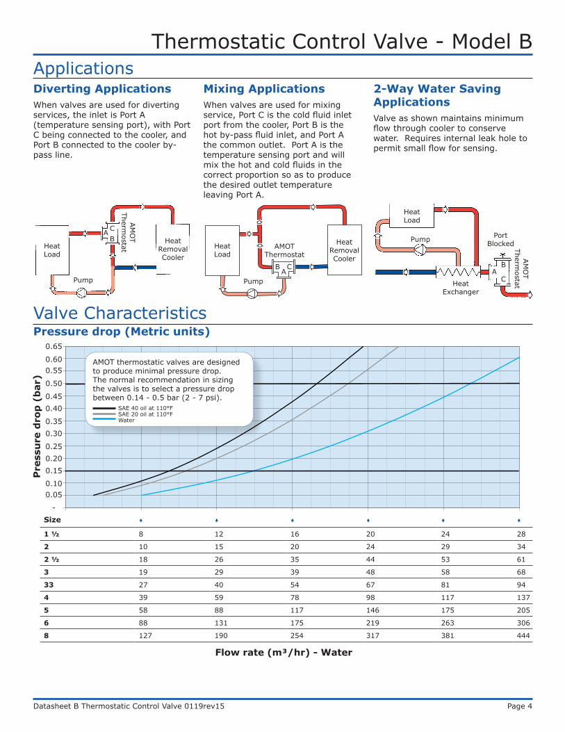
ApplicationsDiverting ApplicationsWhen valves are used for diverting services, the inlet is Port A (temperature sensing port), with Port C being connected to the cooler, and Port B connected to the cooler by-pass line.
Pressure drop (Metric units)
Mixing ApplicationsWhen valves are used for mixing service, Port C is the cold fluid inlet port from the cooler, Port B is the hot by-pass fluid inlet, and Port A the common outlet. Port A is the temperature sensing port and will mix the hot and cold fluids in the correct proportion so as to produce the desired outlet temperature leaving Port A.
2-Way Water Saving ApplicationsValve as shown maintains minimum flow through cooler to conserve water. Requires internal leak hole to permit small flow for sensing.
Heat Load
ABC
AM
OT
Thermostat
Heat Removal Cooler
Pump
Heat Load
AB C
Heat Removal Cooler
Pump
AMOTThermostat
Heat Load
Pump
CA
B
Port Blocked
Valve Characteristics
Heat Exchanger
AM
OT
Thermostat
0.65
0.600.55
0.50
0.450.40
0.350.30
0.250.200.15
0.100.05
-
Pre
ssu
re d
rop
(b
ar)
Size 1 ½ 8 12 16 20 24 28
2 10 15 20 24 29 34
2 ½ 18 26 35 44 53 61
3 19 29 39 48 58 68
33 27 40 54 67 81 94
4 39 59 78 98 117 137
5 58 88 117 146 175 205
6 88 131 175 219 263 306
8 127 190 254 317 381 444
Flow rate (m³/hr) - Water
AMOT thermostatic valves are designed to produce minimal pressure drop. The normal recommendation in sizing the valves is to select a pressure drop between 0.14 - 0.5 bar (2 - 7 psi).
WaterSAE 20 oil at 110°FSAE 40 oil at 110°F
Thermostatic Control Valve - Model B
Datasheet B Thermostatic Control Valve 0119rev15 Page 5
-
1
2
3
4
5
6
7
8
9
10
10 25 40 55 70 85 100 115 130
Pre
ssu
rre
dro
p (
psi
)
Flow rate (US gpm) - Water
B Valve Flow Chart
SAE 40 Oil SAE 20 Oil WaterValve Characteristics Continued
Flow coefficientFlow coefficient (calculated)Size Kv Cv1 ½ 36 422 44 512 ½ 79 813 87 10133 121 1404 176 2035 263 3046 394 4568 571 660
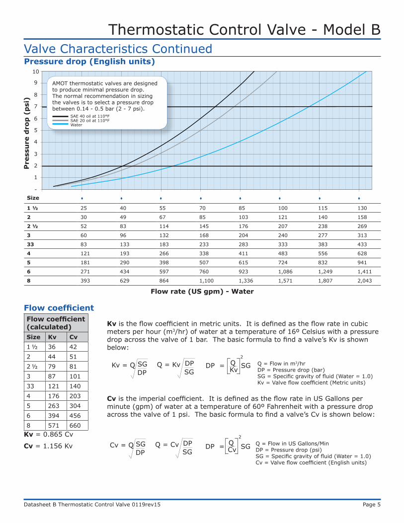
Kv is the flow coefficient in metric units. It is defined as the flow rate in cubic meters per hour (m3/hr) of water at a temperature of 16º Celsius with a pressure drop across the valve of 1 bar. The basic formula to find a valve’s Kv is shown below:
Kv = 0.865 Cv
Cv = 1.156 Kv
Cv is the imperial coefficient. It is defined as the flow rate in US Gallons per minute (gpm) of water at a temperature of 60º Fahrenheit with a pressure drop across the valve of 1 psi. The basic formula to find a valve’s Cv is shown below:
DPSGKv = Q
SGDPQ = Kv
KvDP = SG Q2
Q = Flow in m3/hrDP = Pressure drop (bar)SG = Specific gravity of fluid (Water = 1.0)Kv = Valve flow coefficient (Metric units)
DPSGCv = Q
SGDPQ = Cv
CvDP = SG Q2
Q = Flow in US Gallons/MinDP = Pressure drop (psi)SG = Specific gravity of fluid (Water = 1.0)Cv = Valve flow coefficient (English units)
Pressure drop (English units)
Flow rate (US gpm) - Water
Pre
ssu
re d
rop
(p
si)
10
9
8
7
6
5
4
3
2
1
-Size 1 ½ 25 40 55 70 85 100 115 130
2 30 49 67 85 103 121 140 158
2 ½ 52 83 114 145 176 207 238 269
3 60 96 132 168 204 240 277 313
33 83 133 183 233 283 333 383 433
4 121 193 266 338 411 483 556 628
5 181 290 398 507 615 724 832 941
6 271 434 597 760 923 1,086 1,249 1,411
8 393 629 864 1,100 1,336 1,571 1,807 2,043
AMOT thermostatic valves are designed to produce minimal pressure drop. The normal recommendation in sizing the valves is to select a pressure drop between 0.14 - 0.5 bar (2 - 7 psi).
WaterSAE 20 oil at 110°FSAE 40 oil at 110°F
Thermostatic Control Valve - Model B
Datasheet B Thermostatic Control Valve 0119rev15 Page 6
0.5
0.6
0.7
0.8
0.9
1
1 10 100 1000
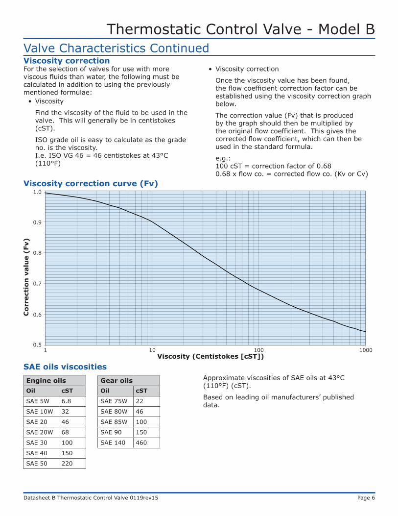
Valve Characteristics ContinuedViscosity correctionFor the selection of valves for use with more viscous fluids than water, the following must be calculated in addition to using the previously mentioned formulae:
• Viscosity
Find the viscosity of the fluid to be used in the valve. This will generally be in centistokes (cST).
ISO grade oil is easy to calculate as the grade no. is the viscosity. I.e. ISO VG 46 = 46 centistokes at 43°C (110°F)
• Viscosity correction
Once the viscosity value has been found, the flow coefficient correction factor can be established using the viscosity correction graph below.
The correction value (Fv) that is produced by the graph should then be multiplied by the original flow coefficient. This gives the corrected flow coefficient, which can then be used in the standard formula.
e.g.: 100 cST = correction factor of 0.68 0.68 x flow co. = corrected flow co. (Kv or Cv)
Viscosity correction curve (Fv)
SAE oils viscositiesEngine oilsOil cST
SAE 5W 6.8
SAE 10W 32
SAE 20 46
SAE 20W 68
SAE 30 100
SAE 40 150
SAE 50 220
Gear oilsOil cST
SAE 75W 22
SAE 80W 46
SAE 85W 100
SAE 90 150
SAE 140 460
Approximate viscosities of SAE oils at 43°C (110°F) (cST).
Based on leading oil manufacturers’ published data.
Cor
rect
ion
val
ue
(Fv)
1.0
0.9
0.8
0.7
0.6
0.51 10 100 1000
Viscosity (Centistokes [cST])
Thermostatic Control Valve - Model B
Datasheet B Thermostatic Control Valve 0119rev15 Page 7
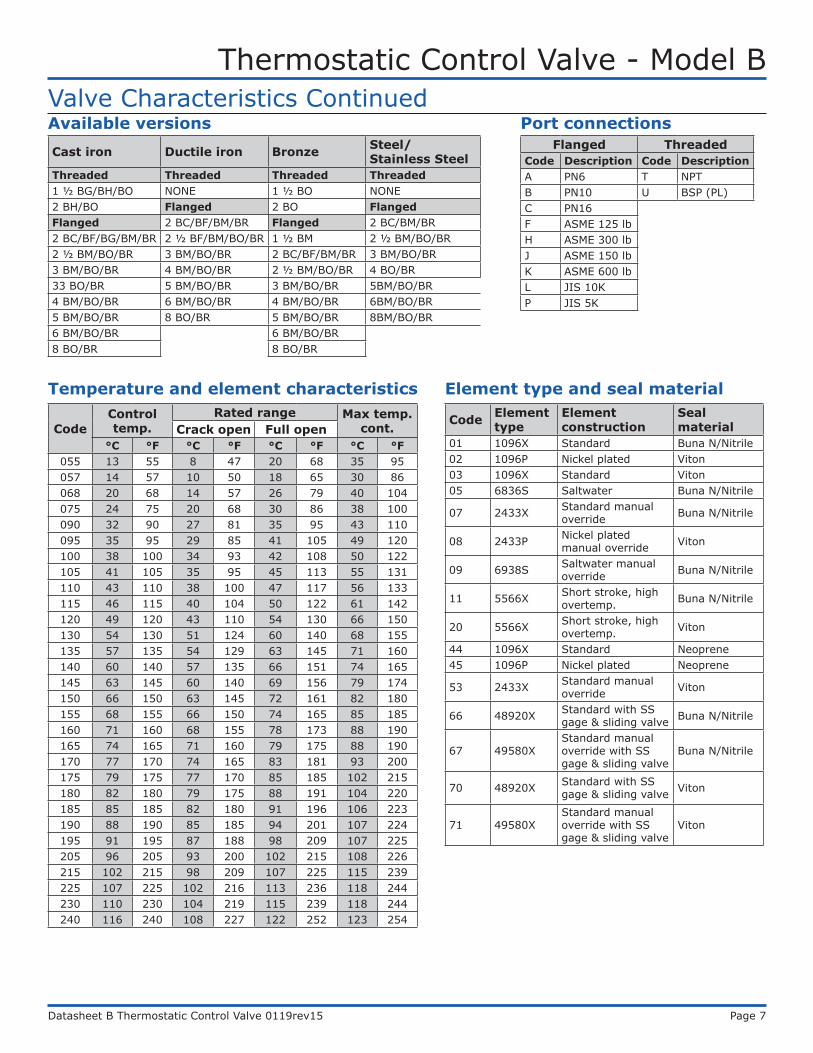
Temperature and element characteristics
CodeControl temp.
Rated range Max temp. cont.Crack open Full open
°C °F °C °F °C °F °C °F055 13 55 8 47 20 68 35 95057 14 57 10 50 18 65 30 86068 20 68 14 57 26 79 40 104075 24 75 20 68 30 86 38 100090 32 90 27 81 35 95 43 110095 35 95 29 85 41 105 49 120100 38 100 34 93 42 108 50 122105 41 105 35 95 45 113 55 131110 43 110 38 100 47 117 56 133115 46 115 40 104 50 122 61 142120 49 120 43 110 54 130 66 150130 54 130 51 124 60 140 68 155135 57 135 54 129 63 145 71 160140 60 140 57 135 66 151 74 165145 63 145 60 140 69 156 79 174150 66 150 63 145 72 161 82 180155 68 155 66 150 74 165 85 185160 71 160 68 155 78 173 88 190165 74 165 71 160 79 175 88 190170 77 170 74 165 83 181 93 200175 79 175 77 170 85 185 102 215180 82 180 79 175 88 191 104 220185 85 185 82 180 91 196 106 223190 88 190 85 185 94 201 107 224195 91 195 87 188 98 209 107 225205 96 205 93 200 102 215 108 226215 102 215 98 209 107 225 115 239225 107 225 102 216 113 236 118 244230 110 230 104 219 115 239 118 244240 116 240 108 227 122 252 123 254
Code Element type
Element construction
Seal material
01 1096X Standard Buna N/Nitrile02 1096P Nickel plated Viton03 1096X Standard Viton05 6836S Saltwater Buna N/Nitrile
07 2433X Standard manual override Buna N/Nitrile
08 2433P Nickel plated manual override Viton
09 6938S Saltwater manual override Buna N/Nitrile
11 5566X Short stroke, high overtemp. Buna N/Nitrile
20 5566X Short stroke, high overtemp. Viton
44 1096X Standard Neoprene45 1096P Nickel plated Neoprene
53 2433X Standard manual override Viton
66 48920X Standard with SS gage & sliding valve Buna N/Nitrile
67 49580XStandard manual override with SS gage & sliding valve
Buna N/Nitrile
70 48920X Standard with SS gage & sliding valve Viton
71 49580XStandard manual override with SS gage & sliding valve
Viton
Element type and seal material
Valve Characteristics Continued
Cast iron Ductile iron Bronze Steel/ Stainless Steel
Threaded Threaded Threaded Threaded1 ½ BG/BH/BO NONE 1 ½ BO NONE2 BH/BO Flanged 2 BO FlangedFlanged 2 BC/BF/BM/BR Flanged 2 BC/BM/BR2 BC/BF/BG/BM/BR 2 ½ BF/BM/BO/BR 1 ½ BM 2 ½ BM/BO/BR2 ½ BM/BO/BR 3 BM/BO/BR 2 BC/BF/BM/BR 3 BM/BO/BR3 BM/BO/BR 4 BM/BO/BR 2 ½ BM/BO/BR 4 BO/BR33 BO/BR 5 BM/BO/BR 3 BM/BO/BR 5BM/BO/BR4 BM/BO/BR 6 BM/BO/BR 4 BM/BO/BR 6BM/BO/BR5 BM/BO/BR 8 BO/BR 5 BM/BO/BR 8BM/BO/BR6 BM/BO/BR 6 BM/BO/BR8 BO/BR 8 BO/BR
Available versionsFlanged Threaded
Code Description Code DescriptionA PN6 T NPTB PN10 U BSP (PL)C PN16F ASME 125 lbH ASME 300 lbJ ASME 150 lbK ASME 600 lbL JIS 10KP JIS 5K
Port connections
Thermostatic Control Valve - Model B
Datasheet B Thermostatic Control Valve 0119rev15 Page 8
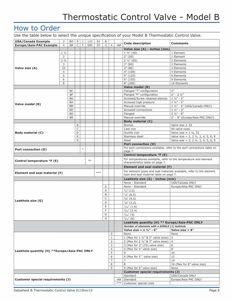
USA/Canada Example 3 BO S J 110 01 BCode description CommentsEurope/Asia-PAC Example 4 BR C F 095 07 -C 4 -AAValve size (A) - inches (mm)
Valve size (A)
1 ½ 1 ½” (40) 1 Element2 2” (50) 1 Element
2 ½ 2 ½” (65) 2 Elements3 3” (80) 2 Elements33 3” (80) 3 Elements4 4” (100) 4 Elements5 5” (125) 6 Elements6 6” (150) 9 Elements8 8” (200) 16 Elements
Valve model (B)
Valve model (B)
BC Flanged “T” configuration 2” BF Flanged “F” configuration 2” - 2 ½”BG Screwed/Screw retained sleeves 1 ½” - 2” BH Screwed high pressure 1 ½” - 2”BM Manual override 1 ½” - 6” (USA/Canada ONLY)BO Screwed connections 1 ½” - 2”BO Flanged 2 ½” - 8”BR Manual override 2” - 8” (Europe/Asia-PAC ONLY)
Body material (C)
Body material (C)
B Bronze Valve size ≠ 33C Cast iron All valve sizesD Ductile iron Valve size ≠ 1 ½, 33R Stainless steel Valve size = 2, 2 ½, 3, 4, 5, 6, 8S Steel Valve size = 2, 2 ½, 3, 4, 5, 6, 8
Port connection (D)
Port connection (D) * For port connections available, refer to the port connections table on page 7.Control temperature °F (E)
Control temperature °F (E) ** For temperatures available, refer to the temperature and element characteristics table on page 7.
Element and seal material (F)
Element and seal material (F) *** For element types and seal materials available, refer to the element type and seal material table on page 7.
Leakhole size (G) - inches (mm)
Leakhole size (G)
None - Standard USA/Canada ONLY 0 None - Standard Europe/Asia-PAC ONLYA 1⁄2” (13)B 1⁄4” (6.5)C 3⁄8” (9.5)D 1⁄8” (3.2)E 1⁄16” (1.6)F 3⁄32” (2.4)G 3⁄16” (5)H 5⁄16” (8)
Leakhole quantity (H) ** Europe/Asia-PAC ONLYNumber of elements with a SINGLE (1) leakhole
Valve size = 1 ½” - 6” Valve size = 8”
Leakhole quantity (H) **Europe/Asia-PAC ONLY
0 None None1 1 (Max for 1 ½” & 2” valve sizes) 22 2 (Max for 2 ½” & 3” valve sizes) 43 3 (Max for 3” (33) valve size) 64 4 (Max for 4” valve size) 85 5 106 6 (Max for 5 “ valve size) 127 7 148 8 16 (Max for 8” valve size)9 9 (Max for 6” valve size) None
Customer special requirements (J)
Customer special requirements (J)Standard USA/Canada ONLY
-AA Standard Europe/Asia-PAC ONLY-*** Customer special code
How to OrderUse the table below to select the unique specification of your Model B Thermostatic Control Valve.
Thermostatic Control Valve - Model B
Datasheet B Thermostatic Control Valve 0119rev15 Page 9
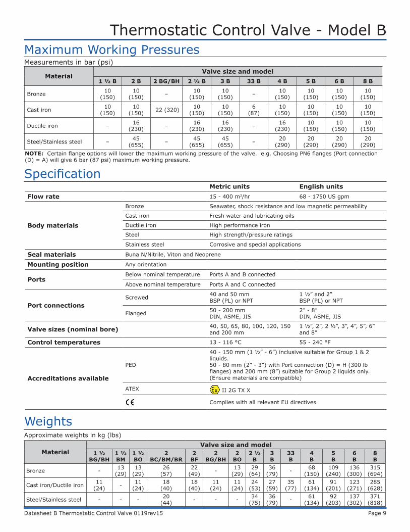
Maximum Working PressuresMeasurements in bar (psi)
MaterialValve size and model
1 ½ B 2 B 2 BG/BH 2 ½ B 3 B 33 B 4 B 5 B 6 B 8 B
Bronze 10 (150)
10 (150) – 10
(150)10
(150) – 10 (150)
10 (150)
10 (150)
10 (150)
Cast iron 10 (150)
10 (150) 22 (320) 10
(150)10
(150)6
(87)10
(150)10
(150)10
(150)10
(150)
Ductile iron – 16 (230) – 16
(230)16
(230) – 16 (230)
10 (150)
10 (150)
10 (150)
Steel/Stainless steel – 45 (655) – 45
(655)45
(655) – 20 (290)
20 (290)
20 (290)
20 (290)
SpecificationMetric units English units
Flow rate 15 - 400 m3/hr 68 - 1750 US gpm
Body materials
Bronze Seawater, shock resistance and low magnetic permeability
Cast iron Fresh water and lubricating oils
Ductile iron High performance iron
Steel High strength/pressure ratings
Stainless steel Corrosive and special applications
Seal materials Buna N/Nitrile, Viton and Neoprene
Mounting position Any orientation
PortsBelow nominal temperature Ports A and B connected
Above nominal temperature Ports A and C connected
Port connectionsScrewed 40 and 50 mm
BSP (PL) or NPT1 ½” and 2” BSP (PL) or NPT
Flanged 50 - 200 mm DIN, ASME, JIS
2” - 8” DIN, ASME, JIS
Valve sizes (nominal bore) 40, 50, 65, 80, 100, 120, 150 and 200 mm
1 ½”, 2”, 2 ½”, 3”, 4”, 5”, 6” and 8”
Control temperatures 13 - 116 °C 55 - 240 °F
Accreditations available
PED
40 - 150 mm (1 ½” - 6”) inclusive suitable for Group 1 & 2 liquids.50 - 80 mm (2” - 3”) with Port connection (D) = H (300 lb flanges) and 200 mm (8”) suitable for Group 2 liquids only. (Ensure materials are compatible)
ATEX II 2G TX X
Complies with all relevant EU directives
MaterialValve size and model
1 ½ BG/BH
1 ½ BM
1 ½ BO
2 BC/BM/BR
2 BF
2 BG/BH
2 BO
2 ½ B
3 B
33 B
4 B
5 B
6 B
8 B
Bronze - 13 (29)
13 (29)
26 (57)
22 (49) - 13
(29)29
(64)36
(79) - 68 (150)
109 (240)
136 (300)
315 (694)
Cast iron/Ductile iron 11 (24) - 11
(24)18
(40)18
(40)11
(24)11
(24)24
(53)27
(59)35
(77)61
(134)91
(201)123
(271)285
(628)
Steel/Stainless steel - - - 20 (44) - - - 34
(75)36
(79) - 61 (134)
92 (203)
137 (302)
371 (818)
WeightsApproximate weights in kg (lbs)
NOTE: Certain flange options will lower the maximum working pressure of the valve. e.g. Choosing PN6 flanges (Port connection (D) = A) will give 6 bar (87 psi) maximum working pressure.
Thermostatic Control Valve - Model B
Datasheet B Thermostatic Control Valve 0119rev15 Page 10
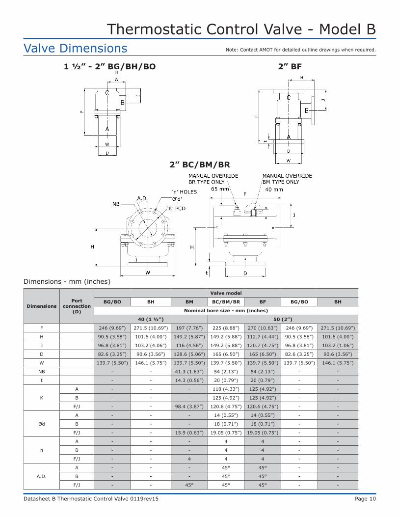
Valve Dimensions2” BF
2” BC/BM/BR
DimensionsPort
connection (D)
Valve model
BG/BO BH BM BC/BM/BR BF BG/BO BH
Nominal bore size - mm (inches)
40 (1 ½”) 50 (2”)
F 246 (9.69”) 271.5 (10.69”) 197 (7.76”) 225 (8.88”) 270 (10.63”) 246 (9.69”) 271.5 (10.69”)
H 90.5 (3.58”) 101.6 (4.00”) 149.2 (5.87”) 149.2 (5.88”) 112.7 (4.44”) 90.5 (3.58”) 101.6 (4.00”)
J 96.8 (3.81”) 103.2 (4.06”) 116 (4.56”) 149.2 (5.88”) 120.7 (4.75”) 96.8 (3.81”) 103.2 (1.06”)
D 82.6 (3.25”) 90.6 (3.56”) 128.6 (5.06”) 165 (6.50”) 165 (6.50”) 82.6 (3.25”) 90.6 (3.56”)
W 139.7 (5.50”) 146.1 (5.75”) 139.7 (5.50”) 139.7 (5.50”) 139.7 (5.50”) 139.7 (5.50”) 146.1 (5.75”)
NB - - 41.3 (1.63”) 54 (2.13”) 54 (2.13”) - -
t - - 14.3 (0.56”) 20 (0.79”) 20 (0.79”) - -
K
A - - - 110 (4.33”) 125 (4.92”) - -
B - - - 125 (4.92”) 125 (4.92”) - -
F/J - - 98.4 (3.87”) 120.6 (4.75”) 120.6 (4.75”) - -
Ød
A - - - 14 (0.55”) 14 (0.55”) - -
B - - - 18 (0.71”) 18 (0.71”) - -
F/J - - 15.9 (0.63”) 19.05 (0.75”) 19.05 (0.75”) - -
n
A - - - 4 4 - -
B - - - 4 4 - -
F/J - - 4 4 4 - -
A.D.
A - - - 45° 45° - -
B - - - 45° 45° - -
F/J - - 45° 45° 45° - -
Dimensions - mm (inches)
1 ½” - 2” BG/BH/BOH
Note: Contact AMOT for detailed outline drawings when required.
Thermostatic Control Valve - Model B
Datasheet B Thermostatic Control Valve 0119rev15 Page 11
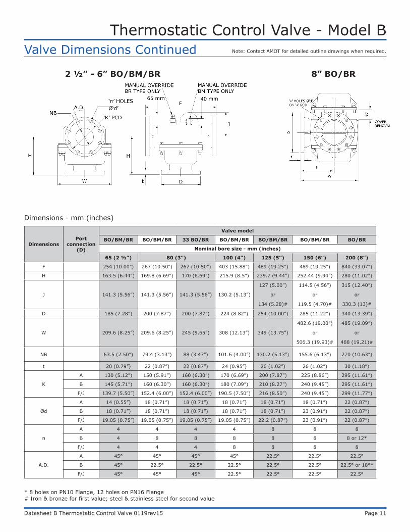
Valve Dimensions Continued
2 ½” - 6” BO/BM/BR 8” BO/BR
DimensionsPort
connection (D)
Valve model
BO/BM/BR BO/BM/BR 33 BO/BR BO/BM/BR BO/BM/BR BO/BM/BR BO/BR
Nominal bore size - mm (inches)
65 (2 ½”) 80 (3”) 100 (4”) 125 (5”) 150 (6”) 200 (8”)
F 254 (10.00”) 267 (10.50”) 267 (10.50”) 403 (15.88”) 489 (19.25”) 489 (19.25”) 840 (33.07”)
H 163.5 (6.44”) 169.8 (6.69”) 170 (6.69”) 215.9 (8.5”) 239.7 (9.44”) 252.44 (9.94”) 280 (11.02”)
J 141.3 (5.56”) 141.3 (5.56”) 141.3 (5.56”) 130.2 (5.13”)
127 (5.00”)
or
134 (5.28)#
114.5 (4.56”)
or
119.5 (4.70)#
315 (12.40”)
or
330.3 (13)#
D 185 (7.28”) 200 (7.87”) 200 (7.87”) 224 (8.82”) 254 (10.00”) 285 (11.22”) 340 (13.39”)
W 209.6 (8.25”) 209.6 (8.25”) 245 (9.65”) 308 (12.13”) 349 (13.75”)
482.6 (19.00”)
or
506.3 (19.93)#
485 (19.09”)
or
488 (19.21)#
NB 63.5 (2.50”) 79.4 (3.13”) 88 (3.47”) 101.6 (4.00”) 130.2 (5.13”) 155.6 (6.13”) 270 (10.63”)
t 20 (0.79”) 22 (0.87”) 22 (0.87”) 24 (0.95”) 26 (1.02”) 26 (1.02”) 30 (1.18”)
K
A 130 (5.12”) 150 (5.91”) 160 (6.30”) 170 (6.69”) 200 (7.87”) 225 (8.86”) 295 (11.61”)
B 145 (5.71”) 160 (6.30”) 160 (6.30”) 180 (7.09”) 210 (8.27”) 240 (9.45”) 295 (11.61”)
F/J 139.7 (5.50”) 152.4 (6.00”) 152.4 (6.00”) 190.5 (7.50”) 216 (8.50”) 240 (9.45”) 299 (11.77”)
Ød
A 14 (0.55”) 18 (0.71”) 18 (0.71”) 18 (0.71”) 18 (0.71”) 18 (0.71”) 22 (0.87”)
B 18 (0.71”) 18 (0.71”) 18 (0.71”) 18 (0.71”) 18 (0.71”) 23 (0.91”) 22 (0.87”)
F/J 19.05 (0.75”) 19.05 (0.75”) 19.05 (0.75”) 19.05 (0.75”) 22.2 (0.87”) 23 (0.91”) 22 (0.87”)
n
A 4 4 4 4 8 8 8
B 4 8 8 8 8 8 8 or 12*
F/J 4 4 4 8 8 8 8
A.D.
A 45° 45° 45° 45° 22.5° 22.5° 22.5°
B 45° 22.5° 22.5° 22.5° 22.5° 22.5° 22.5° or 18°*
F/J 45° 45° 45° 22.5° 22.5° 22.5° 22.5°
* 8 holes on PN10 Flange, 12 holes on PN16 Flange# Iron & bronze for first value; steel & stainless steel for second value
Dimensions - mm (inches)
Note: Contact AMOT for detailed outline drawings when required.

Thermostatic Control Valve - Model B
Datasheet B Thermostatic Control Valve 0119rev15 Page 12
Service kit model number structure
1) Replace Body material (C) and Port connection (D) with “KIT-”.
2) If Special (J) is not blank, please contact the facility.
Example valve part numberA B C D E F G J
1 ½ BO B T 095 01 DExample service kit model number
A B C D E F G J1 ½ BO KIT- 095 01 DA - Valve size D - Port connection G - Leakhole sizeB - Valve model E - Control temperature (°F) J - SpecialC - Body material F - Element and seal material
Maintenance and Service PartsOver time, exposure to foreign chemicals and particulate matter as well as prolonged operation at extreme conditions may reduce the effectiveness of the valve. At such time, AMOT Thermostatic Valves can be restored to original performance by installing an AMOT thermostatic valve service kit or a seal kit and new temperature element(s).
Service kits are ONLY available for purchase from the Americas and Canada locations. If ordering from the Europe or Asia-PAC locations please purchase a seal kit and element to properly service your valve.
Service kits include all new thermostatic element(s), seals and gasket required for normal maintenance. Seal kits include new seals and gasket(s). Whenever element(s) are replaced, the seals and gasket(s) should also be replaced.
AMOT recommends fully servicing thermostatic control valves with each regularly scheduled major overhaul of the turbine, engine, compressor or other associated equipment. AMOT recommends a service interval of not more than 24 months to ensure optimum valve performance.
AMOT designs and tests all its products to ensure that high quality standards are met. For good product life, carefully follow AMOT’s installation and maintenance instructions; failure to do so could result in damage to the equipment being protected or controlled.
Thermostatic service kits may also be used for adapting valves to new service temperatures. Please request a new nameplate when adapting valves to a new service temperature by contacting the facility.
Ordering from Americas and Canada
Service kits are ONLY available for purchase from the Americas and Canada locations.
Service kits are available with element(s), seals and gasket required to service the valve. Order service kits using the AMOT valve part number and nominal temperature setting. Refer to the AMOT valve part number that is printed on the valve nameplate and the AMOT valve part number structure on page 8. The nominal temperature setting is also stamped onto the element flange.
AMOT does NOT offer service kits for 8BO or 8BR Model B Thermostatic Valves. In order to properly service an 8BO and/or 8BR valve please purchase an element and seal kit. Refer to the ordering instructions on page 12.
Ordering from Europe and Asia-PACSeal kits
Seal kits are available with seals and gasket(s) only. Order seal kits using the seal kit model number which is identified by the valve size and element/seal material code from the AMOT valve part number. Refer to the AMOT valve part number that is printed on the valve nameplate and the AMOT valve part number structure on page 8.
Element(s)
Order temperature elements using the element part number which is identified by the element/seal material code and nominal temperature setting from the AMOT valve part number. Refer to the AMOT valve part number that is printed on the valve nameplate and the AMOT valve part number structure on page 8.
Service kits
Thermostatic Control Valve - Model B
Datasheet B Thermostatic Control Valve 0119rev15 Page 13
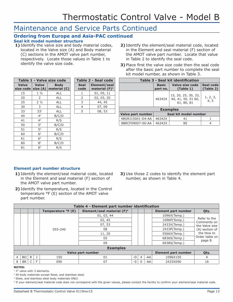
Table 3 - Seal kit identificationBasic
part no.Valve size code
(Table 1)Seal code (Table 2)
46342X15, 20, 25, 30, 33, 40, 41, 50, 51 60,
61, 80, 81
1, 2, 3, 4, 5
ExamplesValve part number Seal kit model number4BORJ15001-D4-AA 46342X 41 18BRCF09007-00-AA 46342X 80 4
NOTES:1 3” valve with 3 elements.2 All body materials except Steel, and stainless steel.3 Steel, and stainless steel body materials ONLY.4 If your element/seal material code does not correspond with the given values, please contact the facility to confirm your element/seal material code.
Maintenance and Service Parts ContinuedOrdering from Europe and Asia-PAC continued
1) Identify the valve size and body material codes, located in the Valve size (A) and Body material (C) sections in the AMOT valve part number, respectively. Locate those values in Table 1 to identify the valve size code.
2) Identify the element/seal material code, located in the Element and seal material (F) section of the AMOT valve part number. Locate that value in Table 2 to identify the seal code.
3) Place first the valve size code then the seal code after the basic part number to complete the seal kit model number, as shown in Table 3.
Table 4 - Element part number identificationTemperature °F (E) Element/seal material (F)4 Element part number Qty.
055-240
01, 03, 44 1096X(Temp.)Refer to the
Comments on the Valve size (A) section of the How to
Order table on page 8.
02, 45 1096P(Temp.)07, 53 2433X(Temp.)
08 2433P(Temp.)11, 20 5566X(Temp.)
05 6836S(Temp.)09 6938S(Temp.)
ExamplesValve part number Element part number Qty.
4 BO R J 150 01 -D 4 -AA 1096X150 48 BR C F 090 07 -0 0 -AA 2433X090 16
Element part number structure1) Identify the element/seal material code, located
in the Element and seal material (F) section of the AMOT valve part number.
2) Identify the temperature, located in the Control temperature °F (E) section of the AMOT valve part number.
3) Use those 2 codes to identify the element part number, as shown in Table 4.
Seal kit model number structure
Table 1 - Valve size codeValve
size codeValve
size (A)Body
material (C)15 1 ½ ALL20 2 ALL25 2 ½ ALL30 3 ALL33 331 ALL40 42 B/C/D41 43 R/S50 52 B/C/D51 53 R/S60 62 B/C/D61 63 R/S80 82 B/C/D81 83 R/S
Table 2 - Seal codeSeal code
Element/seal material (F)4
1 01, 05, 112 02, 03, 203 44, 454 07, 095 08, 53
Thermostatic Control Valve - Model B
Datasheet B Thermostatic Control Valve 0119rev15 Page 14
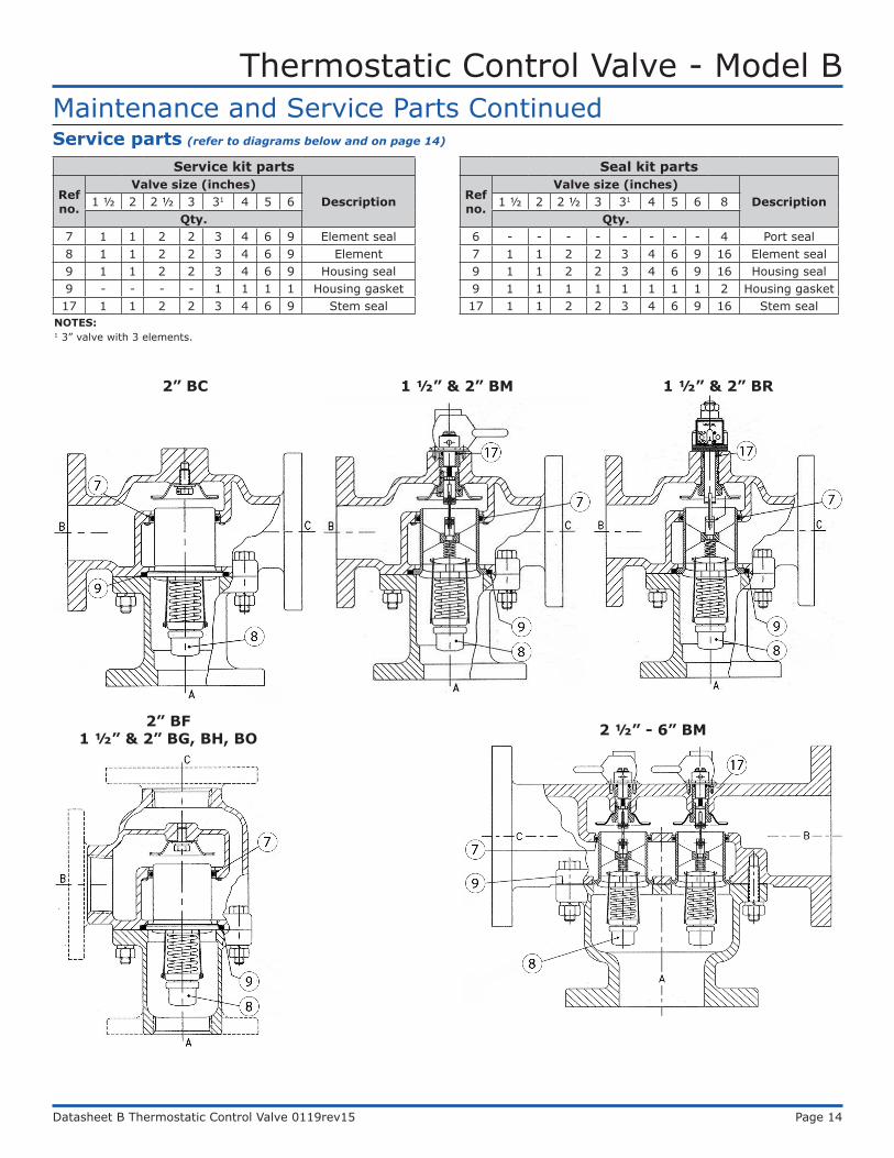
Service parts (refer to diagrams below and on page 14)
Service kit parts
Ref no.
Valve size (inches)Description1 ½ 2 2 ½ 3 31 4 5 6
Qty.7 1 1 2 2 3 4 6 9 Element seal8 1 1 2 2 3 4 6 9 Element9 1 1 2 2 3 4 6 9 Housing seal9 - - - - 1 1 1 1 Housing gasket17 1 1 2 2 3 4 6 9 Stem seal
Seal kit parts
Ref no.
Valve size (inches)Description1 ½ 2 2 ½ 3 31 4 5 6 8
Qty.6 - - - - - - - - 4 Port seal7 1 1 2 2 3 4 6 9 16 Element seal9 1 1 2 2 3 4 6 9 16 Housing seal9 1 1 1 1 1 1 1 1 2 Housing gasket17 1 1 2 2 3 4 6 9 16 Stem seal
2” BC 1 ½” & 2” BM
2” BF 1 ½” & 2” BG, BH, BO 2 ½” - 6” BM
Maintenance and Service Parts Continued
NOTES:1 3” valve with 3 elements.
1 ½” & 2” BR
Thermostatic Control Valve - Model B
Datasheet B Thermostatic Control Valve 0119rev15 Page 15
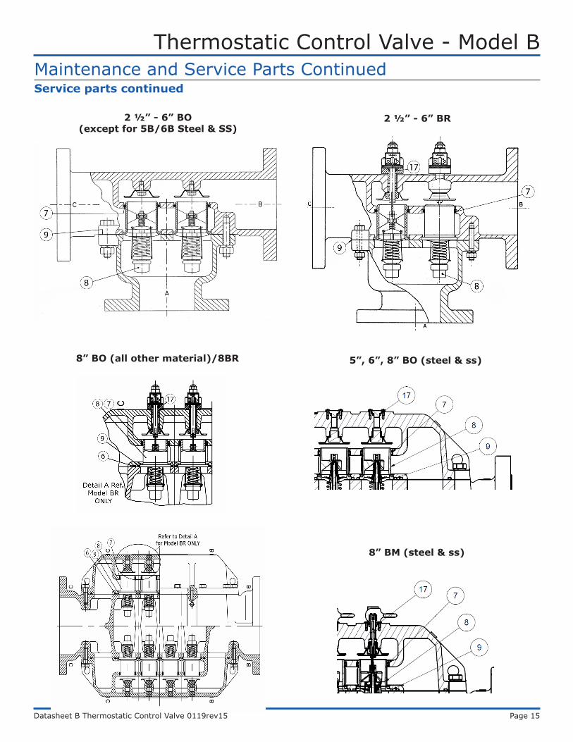
8” BO (all other material)/8BR
2 ½” - 6” BR2 ½” - 6” BO (except for 5B/6B Steel & SS)
Maintenance and Service Parts ContinuedService parts continued
5”, 6”, 8” BO (steel & ss)
8” BM (steel & ss)
Thermostatic Control Valve - Model B
Datasheet B Thermostatic Control Valve 0119rev15 Page 16
Contact
Americas Europe, Middle East and Africa
AMOT USA8824 Fallbrook Dr.Houston, TX 77064USA
Tel: +1 (281) 940 1800Fax: +1 (713) 559 9419Email: [email protected]
AMOT UKWestern WayBury St. EdmundsSuffolk, IP33 3SZEngland
Tel: +44 1284 715739Fax: +44 1284 760256Email: [email protected]
AMOT GermanyRondenbarg 2522525 HamburgGermany
Tel: +49 40 8537 1298Fax: +49 40 8537 1331Email: [email protected] Pacific
AMOT ShanghaiBd. 7A, No. 568, Longpan Rd., Malu JiadingShanghai 201801China
Tel: +86 21 5910 4052Fax: +86 21 5237 8560Email: [email protected]
www.amot.com
Related Documents