APPLICATION REPORT 2621/06/01 EN • 12/2011 THERMOMECHANICAL PULPING Overview of the process Thermomechanical pulping, TMP, is precisely named. Pulp is made by heating the chips with steam and mechanically separating the fibers in a pressurized refiner. While high in energy consumption, TMP produces strong fibers, and clean steam can be recovered. The process Chips are fed to a presteamer and are steamed with process steam from the refiners. A feed- ing screw (plug feeder) moves the chips to a pressurized refiner which separates the fiber via mechanical means (e.g. between rotating disc plates). The refiner is followed by a cyclone to separate the pulp from the process steam. The pulp is of- ten refined in two stages. The process steam is taken to the heat recovery unit to produce clean steam.

Welcome message from author
This document is posted to help you gain knowledge. Please leave a comment to let me know what you think about it! Share it to your friends and learn new things together.
Transcript
APPLICATION REPORT2621/06/01 E
N • 12/2011
THERMOMECHANICAL PULPING
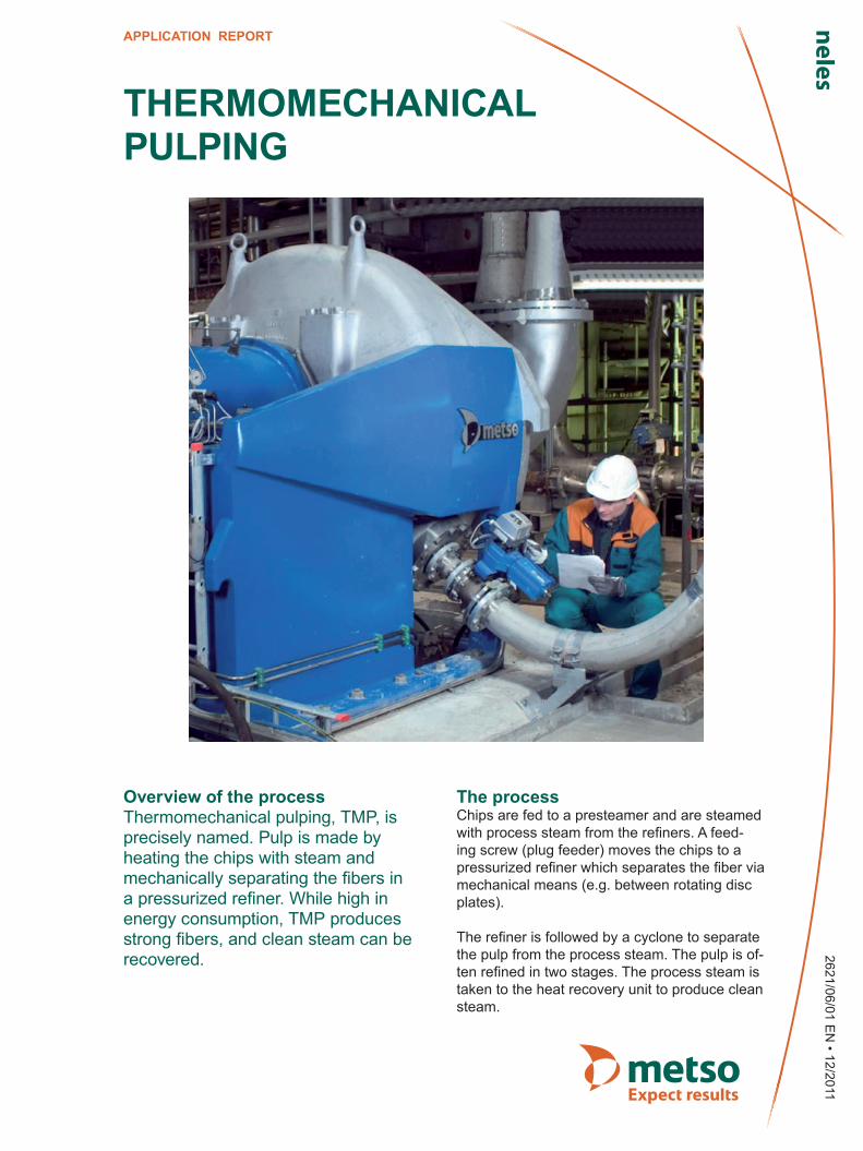
Overview of the processThermomechanical pulping, TMP, is precisely named. Pulp is made by heating the chips with steam and mechanically separating the fibers in a pressurized refiner. While high in energy consumption, TMP produces strong fibers, and clean steam can be recovered.
The processChips are fed to a presteamer and are steamed with process steam from the refiners. A feed-ing screw (plug feeder) moves the chips to a pressurized refiner which separates the fiber via mechanical means (e.g. between rotating disc plates).
The refiner is followed by a cyclone to separate the pulp from the process steam. The pulp is of-ten refined in two stages. The process steam is taken to the heat recovery unit to produce clean steam.
2621/06/01 EN THERMOMECHANICAL PULPING
2 APPLICATION REPORT 12/11
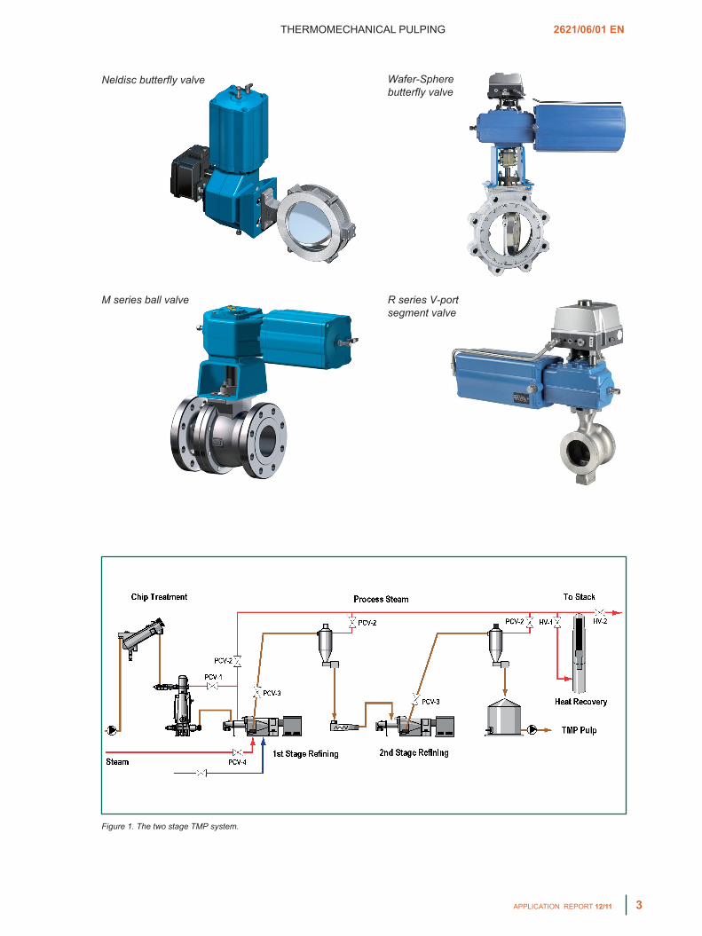
The resultsThe Pre-steamer is heated with the process steam via valve PCV-1 to typically 1 to 2 bar or 130 to 140 °C (15 to 30 psig, 266 to 284 °F). After a retention time of couple minutes, the pressur-ized chips is fed to the refiner. The refiner may be fed with fresh steam via valve PCV-4, during startup, to increase the pressure up to 4...5 barg or 150 °C (60...75 psig or 300 °F).
The refiner discharges the pulp and steam to a cyclone. The cyclone separates the steam from the pulp. The valves (PCV-1, PCV-2) in the process steam line control the pressure in the refiner. During production this steam is sent to heat recovery, while in the start-up it goes to the steam stack for disposal. The TMP pulp (35 %) is discharged through valve PCV-3 from the first stage refiner to the second stage and from there to further treatment in the screening, cleaning etc.
Valve selectionThe control of fresh steam in PCV-4 can be eas-ily accomplished by the R series segment valve. The process steam, however, has a tendency to contain ersin end fibers which can build up and result in potential plugging problems in valves PCV-1 and PCV-2. Neldisc® has performed well in this application. Because of fines and fibers present the use of Q-Trims in the process steam must be evaluated with care.
The TMP discharge (blow) valve PCV-3 contains TMP pulp (35 % consistency), and steam/con-densate. Because of the high pressure drop of the system, this valve must withstand erosion. One solution is a segment type valve, flanged, expanded outlet with stellited internals. Also metal seated ball valves are used. The water (white or fresh) control valve should all be R se-ries segment valves for optimal control.
Not shown in the drawing is a refiner relief valve which will discharge the refiner contents quickly when needed to protect the refiner (exceeding a set pressure, broken plates, etc.). Full bore ball valve, M series, with locked seats (P) equipped with a fail open quick action actuator should be selected.
VALVE SELECTION
Tag Application Recommended AlternatePCV-1, PCV-2 Steam (process) Neldisc triple eccentric disc valve Wafer-Sphere® butterfly valve
PCV-3 Refiner blow R2_S V-port segment valve M series
PCV-4 Steam (fresh) R series V-port segment valve M series
-------- Water (control) R series V-port segment valve M series
-------- Refiner relief M series ball valve P seat --------
THERMOMECHANICAL PULPING 2621/06/01 EN
APPLICATION REPORT 12/11 3
Figure 1. The two stage TMP system.
Neldisc butterfly valve
M series ball valve
Wafer-Sphere butterfly valve
R series V-port segment valve

The information provided in this bulletin is advisory in nature, and is intended as a guideline only. For specific circumstances and more detailed information, please consult with your local automation expert at Metso.
Metso Automation Inc.Europe, Vanha Porvoontie 229, P.O. Box 304, FI-01301 VANTAA, Finland. Tel. +358 20 483 150. Fax +358 20 483 151North America, 44 Bowditch Drive, P.O. Box 8044, Shrewsbury, MA 01545, USA. Tel. +1 508 852 0200. Fax +1 508 852 8172South America, Av. Independéncia, 2500- Iporanga, 18087-101, Sorocaba-São Paulo Brazil. Tel. +55 15 2102 9700. Fax +55 15 2102 9748/49Asia Pacific, 20 Kallang Avenue, Lobby B, #06-00, PICO Creative Centre, Singapore 339411, Singapore. Tel. +65 6511 1011. Fax +65 6250 0830 China, 19/F, the Exchange Beijing, No. 118, Jianguo Lu Yi, Chaoyang Dist, 100022 Beijing, China. Tel. +86-10-6566-6600. Fax +86-10-6566-2575Middle East, Roundabout 8, Unit AB-07, P.O. Box 17175, Jebel Ali Freezone, Dubai, United Arab Emirates. Tel. +971 4 883 6974. Fax +971 4 883 6836www.metso.com/valves
APPLICATION REPORT
Related Documents