Thermoelectric Materials for Waste Heat Recovery Review paper as part of ENE601 autumn 2013 Author: Gunstein Skomedal

Welcome message from author
This document is posted to help you gain knowledge. Please leave a comment to let me know what you think about it! Share it to your friends and learn new things together.
Transcript
Thermoelectric Materials for Waste Heat
Recovery
Review paper as part of ENE601 autumn 2013
Author: Gunstein Skomedal
1
CONTENTS
1 Introduction ......................................................................................................................... 2
2 Waste heat recovery ............................................................................................................ 3
3 Thermoelectricity ................................................................................................................ 4
4 Thermoelectric Materials .................................................................................................... 6
4.1 Important material properties ...................................................................................... 7
4.1.1 Thermoelectric properties .................................................................................... 7
4.1.2 Mechanical properties .......................................................................................... 8
4.1.3 Chemical properties .............................................................................................. 8
4.1.4 Synthesis ............................................................................................................... 9
4.1.5 Abundance .......................................................................................................... 10
4.1.6 Health and environmental impact ...................................................................... 10
4.2 State-of-the-art materials ........................................................................................... 11
4.2.1 Low temperature, < 200°C ................................................................................. 11
4.2.2 Medium temperature, 200 – 600°C .................................................................... 11
4.2.3 High temperature, > 600°C ................................................................................ 12
4.3 New materials ............................................................................................................ 12
4.3.1 Skutterudites ....................................................................................................... 12
4.3.2 Clathrates ............................................................................................................ 13
4.3.3 Mg2BIV
solid solutions ....................................................................................... 14
4.3.4 Silicides .............................................................................................................. 15
4.3.5 Half-Heussler compounds .................................................................................. 15
4.3.6 Oxides ................................................................................................................. 15
4.3.7 Zn4Sb3 ................................................................................................................. 16
5 Summary and conclusion .................................................................................................. 19
References ................................................................................................................................ 20
2
1 INTRODUCTION
Our world hungers for energy. As global population is growing and more and more people
will increase their quality of life, this will also yield higher energy consumption. According to
recent report the energy demand will continue to increase by 30-40% the next 20 years [1, 2].
Today most of the energy, around 80%, comes from fossil fuels and will continue to do so in
the near future. Because of the greenhouse gases these energy conversion technologies emits,
along with its inherent non-sustainable usage of limited resources, others sources of energy
will eventually need to take over a much higher portion of the energy production. Renewables,
even though it accounts for very small portions of the energy production today, is believed to
take care of much of the growth in energy production in the last part of this century. But
producing more clean and renewable energy is not the only solution. We also need to utilize
the energy we already produce in a much more efficient way.
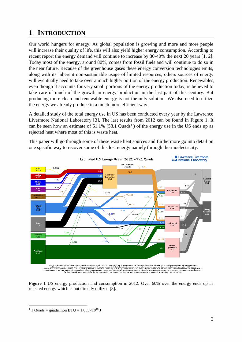
A detailed study of the total energy use in US has been conducted every year by the Lawrence
Livermore National Laboratory [3]. The last results from 2012 can be found in Figure 1. It
can be seen how an estimate of 61.1% (58.1 Quads1 ) of the energy use in the US ends up as
rejected heat where most of this is waste heat.
This paper will go through some of these waste heat sources and furthermore go into detail on
one specific way to recover some of this lost energy namely through thermoelectricity.
Figure 1 US energy production and consumption in 2012. Over 60% over the energy ends up as
rejected energy which is not directly utilized [3].
1 1 Quads = quadrillion 1.055×10
18 J BTU =
3
2 WASTE HEAT RECOVERY
Waste heat can be defined as “heat energy in the shape of hot air, steam or fluid which are not
utilized in the energy production process and is therefore lost to the environment” 2. The
major part of the rejected energy seen in Figure 1 is waste heat resulting from the burning of
fossil fuels in electric power production and high temperature industrial processes. The
transport sector also account for a very large part of the rejected energy (21.1 Quads). In a
normal gasoline engine for cars only about 25% of the energy is converted into useful energy
while the rest is rejected through coolant and exhaust gases as waste heat [4]. It is obvious
that the potential for utilizing this energy better is enormous.
In a report on waste heat in Norway from Enova in 2009 it was concluded that around 25% of
waste heat in Norwegian industry could be exploited for waste heat recovery [5]. Though here
only existing technologies like steam-turbine, steam-engine, Stirling-engine and ORC
(organic rankine cycle) where discussed. The recent decision to install a new energy recovery
system at Elkem Salten3, which will recover 30% of the electricity consumption, is just one
examples of how more and more effort is put into exploiting this potential [6].
A similar report on waste heat recovery technologies and opportunities in the US industry
concluded that most of the potential of waste heat recovery on large-scale industrial plants
with clean gaseous exhaust streams where already in a large extent exploited [7]. But for
dirtier exhaust gases, smaller scale applications, and lower temperature waste heat streams,
energy recovery is seldom installed and should therefore be further developed.
Heat recovery has it theoretical foundation in thermodynamics. Waste heat has a lower energy
value (a higher entropy) than other forms of energy such as electricity. The carnot efficiency
is the highest theoretical efficiency a heat recovery system can obtain and is given by
⁄ , where TH is the temperature of the waste heat, TC the temperature of the
cold side heat exchanger and the ratio between the work done by the system (for example
electricity generated) and the heat energy supplied. This equation shows how the higher the
temperature of the waste heat is, the more efficient can this energy be exploited further. It is
therefore obvious that the waste heat recovery programs such as the ones supported by Enova
aims at picking the lowest hanging apples first where either the waste heat can be directly
used as district heating (only energy loss during transport) or the higher temperature and
volume waste heat sources where the conversion efficiency is the highest.
The higher hanging apples, where the temperature is too low or the energy volume too small,
are seldom considered usable with existing technology to encompass investment in energy
recovery systems. Steam turbines, which are the most used technology for converting heat
into electricity, takes up a lot of extra space, need extra maintenance and complicates the total
process further while also having a much higher cost per watt produced at lower temperatures.
The same factors limit most of the existing waste heat recovery technologies.
Thermoelectric generator (TEG) is one technology that has a huge potential when it comes to
utilizing parts of this waste heat energy source [8]. A TEG is a solid-state device that converts
a heat flow directly into electric energy without any moving parts (see section 3 for a more
2 Norwegian encyclopedia, Store Norske Leksikon, available online on snl.no/spillvarme (30.10.13)
3 Elkem Salten is ferrosilicon and silicon plant north in Norway.
4
detailed description). It is also easily scalable to any size, and can be utilized also for lower
temperature waste heat recovery purposes. On the negative side, TEG technology is still not
fully developed and todays solutions have quite low efficiency (~5%) and are yet very
expensive. But this is about to change.
The thermoelectric market as a whole is believed to be a multibillion USD industry within
2023 [9], where three main areas of applications is seen; waste heat recovery systems in cars,
wireless sensor applications and other consumer applications. The main challenge now is up-
scaling the production processes of known thermoelectric materials to lower the price. It is
believed that this growth will also open up other areas convenient for thermoelectric energy
harvesting, especially for waste heat recovery purposes.
3 THERMOELECTRICITY
In 1821 Thomas Johann Seebeck discovered something interesting; when connecting to
dissimilar metals on both ends and heating one of these connection, he was able to measure a
magnetic field at the other end. It was later proven that this was indeed an electric potential he
had measured. For a material, the Seebeck coefficient is denoted by ⁄ where dV is
the electric potential corresponding to the electromotive force (emf) induced by the
temperature difference, dT. 13 years later Jean Charles Athanase Peltier discovered the
opposite effect; when applying an electrical current over the connection of two dissimilar
metals, heat was generated at the junction. The Peltier coefficient is defined as
⁄ where is the heat flow and I the electric current. A continuous version of the Peltier
effect was described by Lord Kelvin in 1851 where the Thomson coefficient is introduced.
The Thomson coefficient is defined as , where is the heat generated per unit
volume and J is the current density. Together these three effects constitute what we call the
thermoelectric effect; a heat difference over a material generates a corresponding voltage
which under an external load will produce an electric current. The thermoelectric conversion
efficiency of a material is thus the ratio of electric energy produced over the heat energy
supplied [10].
In the early 20th
century Altenkirch expanded the theory of thermoelectricity when defining
the figure of merit of a material
⁄ (1)
where is the electrical conductivity and the thermal conductivity. Z has the unit K-1
so
often Z is multiplied with temperature to give the dimensionless figure of merit ZT. Mostly
metals with high S where assessed in the beginning. But these seldom reached conversion
efficiencies of more than a few percent as the Seebeck coefficient were low and heat quickly
dissipated through the metals with high electrical and thus thermal conductivity (Wiedemann-
Franz law, see section 4.1). It wasn’t until the advances in quantum mechanics gave away for
a completely new understanding of the electric and thermal properties of materials in the
middle of the 20th
century that new semiconducting materials where studied on a large scale,
especially by the Ioffe institute in former Soviet Union and RCA laboratory in the US. In a
semiconductor both the Seebeck coefficient and electrical conductivity can be manipulated
5
with doping of elements with a different valens than the host material and ZT values of up to
1.5 was reported.
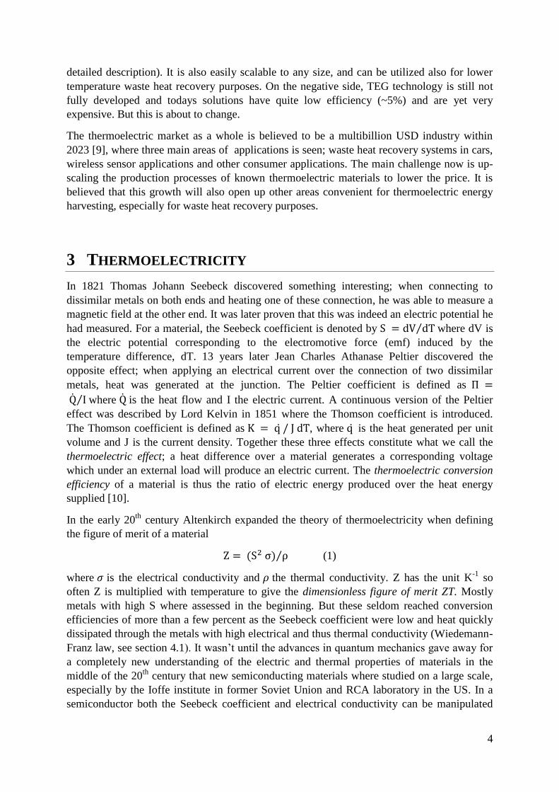
Figure 2 Typical thermoelectric module with n- and p-type TE-legs connected in series. Heat is
absorbed on one side and rejected on the opposite side producing a current through the TE-legs.
Copied from [11].
The first thermoelectric coolers and generators (modules) were also designed around these
times. In principal a thermoelectric module is made of small dice of alternately n and p type
semiconductors connected electrically in series as seen in Figure 2. When one end of the
module is heated and the other is cooled, charge carriers in the material (electrons in n-type
and holes in p-type) will diffuse from the hot to the cold side and thus produce electric power.
The efficiency of these modules can be expressed directly as a function of the temperature on
hot side (TH) and cold side (TC) and ZT as
√
√
(2)
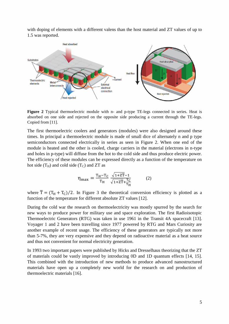
where ⁄ . In Figure 3 the theoretical conversion efficiency is plotted as a
function of the temperature for different absolute ZT values [12].
During the cold war the research on thermoelectricity was mostly spurred by the search for
new ways to produce power for military use and space exploration. The first Radioisotopic
Thermoelectric Generators (RTG) was taken in use 1961 in the Transit 4A spacecraft [13].
Voyager 1 and 2 have been travelling since 1977 powered by RTG and Mars Curiosity are
another example of recent usage. The efficiency of these generators are typically not more
than 5-7%, they are very expensive and they depend on radioactive material as a heat source
and thus not convenient for normal electricity generation.
In 1993 two important papers were published by Hicks and Dresselhaus theorizing that the ZT
of materials could be vastly improved by introducing 0D and 1D quantum effects [14, 15].
This combined with the introduction of new methods to produce advanced nanostructured
materials have open up a completely new world for the research on and production of
thermoelectric materials [16].
6
Figure 3 Theoretical maximum conversion efficiency of a thermoelectric generator as a function of
temperature and ZT values (see equation 2).
The discovery of new materials with ZT values over 2 combined with the rising concern on
growing energy demand in our world have caused many new research project on how to
utilize thermoelectricity as a new mean to produce and recover energy. Already
thermoelectric energy conversion is finding its way into waste heat recovery for smaller
systems where especially space and weight is of a concern. Almost all the challenges for
further development are material related where some of the most important are:
low efficiency materials
too expensive materials and systems
low durability at high temperatures
toxic compounds
low abundance of raw materials
It is obvious that all these aspects should be evaluated when deciding on materials for future
mass production processes to get the most cost efficient and sustainable outcome. Only this
way is it possible for thermoelectric energy conversion to be a part of the solution on waste
heat recovery.
4 THERMOELECTRIC MATERIALS
There exists a wide variety of different thermoelectric (TE) materials today. Some of them
have been known and used for decades while others are a result of more recent developments
of both understanding of the physics and more advanced production processes. TE materials
can be categorized on many different levels such as crystal structure, conversion efficiency,
cost and temperature range. The temperature regime for most typical waste heat energy
7
sources is between 300-700°C (mainly transportation and process industry) so the focus will
be on materials which can handle temperatures in this range.
4.1 IMPORTANT MATERIAL PROPERTIES When discussing the material properties it is important to not only look at one factor alone,
but the combination of several of the factors depending on usage. For example, thermoelectric
materials used in cars should be a trade-off between the conversion efficiency and other
factors that will influence price and durability, such as raw material price or production
process. In the other end of the scale, high efficiency materials that are more expensive could
be utilized on small scale applications where the total cost of the system is mainly governed
by other things than the thermoelectric module itself.
4.1.1 Thermoelectric properties
The thermoelectric properties yield the conversion efficiency of the material and are thus the
most important properties when evaluating thermoelectric materials. As already mentioned in
section 3, these can be summarized in the ZT value of the material which is realted to the
Seebeck coefficient (S), the electrical conductivity (σ) and the thermal conductivity (ρ)
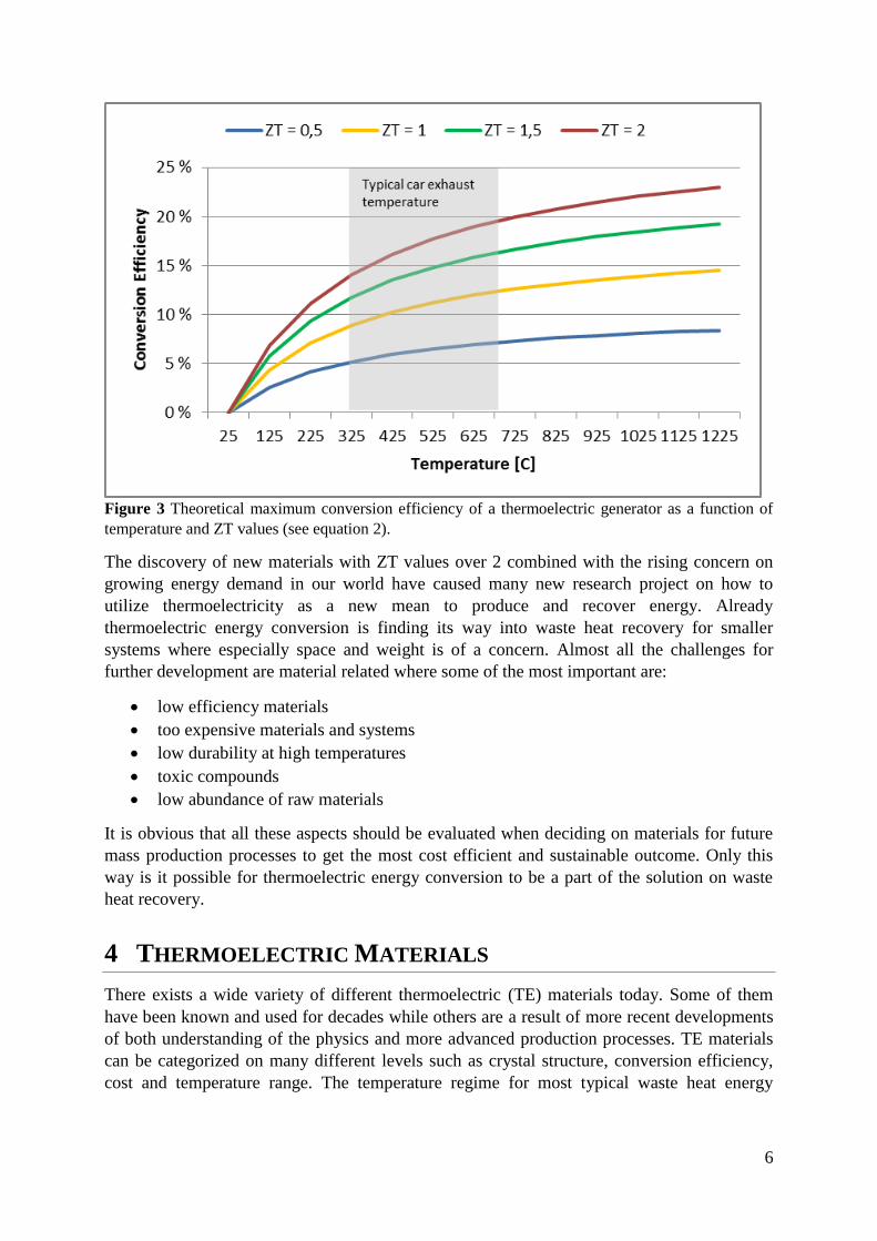
according to equation (1). All these values are dependent on the charge carrier density of the
material as seen in Figure 4. This is mainly because diffusion of charge carriers is the main
transport mechanism to consider in the metals and semiconductors [17].
The Seebeck coefficient measures in practice the entropy transported by moving charge
carriers divided by the carrier’s charge and can be described by the equation
⟨ ⟩ (3)
where e is the electrical charge, EF the Fermi energy and ⟨ ⟩ the average energy per
carrier. The electrical conductivity of a material based on the number of charge carriers, n, is
given by
(4)
where µ is the mobility of the charge carrier and e the elementary charge. The heat transport
in a material is a function of the lattice vibration (phonons) and electron movement given by
the Wiedemann–Franz law:
and (5 a-b)
Here and is the electronic and phonon contribution to the thermal conductivity
respectively and L is the Lorenz factor 4 . From these equations, it can be seen how the
electronic contribution of the thermal conductivity is linearly dependent on the electric
conductivity. Since the ratio σ/ρ should be maximized to increase the ZT value, must be
reduced. This has led to the optimal thermoelectric material being called a “Phonon-glass,
electron-crystal” where the phonons are disrupted as in a glass (amorphous material) while the
electrons can move more freely as in a crystalline material.
4
(
) 2.4 x 10
-8 J
2K
-2 for free electrons. The Wiedmann-Franz law is only strictly true for metals but
can be used as an approximation also for semiconductors where other values of L should be found
experimentally
8
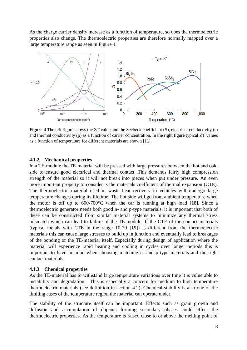
As the charge carrier density increase as a function of temperature, so does the thermoelectric
properties also change. The thermoelectric properties are therefore normally mapped over a
large temperature range as seen in Figure 4.
Figure 4 The left figure shows the ZT value and the Seebeck coefficient (S), electrical conductivity (s)
and thermal conductivity (p) as a function of carrier concentration. In the right figure typical ZT values
as a function of temperature for different materials are shown [11].
4.1.2 Mechanical properties
In a TE-module the TE-material will be pressed with large pressures between the hot and cold
side to ensure good electrical and thermal contact. This demands fairly high compression
strength of the material so it will not break into pieces when put under pressure. An even
more important property to consider is the materials coefficient of thermal expansion (CTE).
The thermoelectric material used in waste heat recovery in vehicles will undergo large
temperature changes during its lifetime. The hot side will go from ambient temperature when
the motor is off up to 600-700°C when the car is running at high load [18]. Since a
thermoelectric generator needs both good n- and p-type materials, it is important that both of
these can be constructed from similar material systems to minimize any thermal stress
mismatch which can lead to failure of the TE-module. If the CTE of the contact materials
(typical metals with CTE in the range 10-20 [19]) is different from the thermoelectric
materials this can cause large stresses to build up in junction and eventually lead to breakages
of the bonding or the TE-material itself. Especially during design of application where the
material will experience rapid heating and cooling in cycles over longer periods this is
important to have in mind when choosing matching n- and p-type materials and the right
contact materials.
4.1.3 Chemical properties
As the TE-material has to withstand large temperature variations over time it is vulnerable to
instability and degradation. This is especially a concern for medium to high temperature
thermoelectric materials (see definition in section 4.2). Chemical stability is also one of the
limiting cases of the temperature region the material can operate under.
The stability of the structure itself can be important. Effects such as grain growth and
diffusion and accumulation of dopants forming secondary phases could affect the
thermoelectric properties. As the temperature is raised close to or above the melting point of
9
some of the constituents of the TE-material, these can sublimate. One example of this is Sb in
CoSb3 which will start to sublimate of the surface at around 550°C in inert atmospheres [20].
Most of the TE-materials are based on metals or semimetals which none are especially noble.
This means that they will all be attacked by oxygen when exposed to air. At lower
temperatures normally the oxide layer is just a few nanometers thick, which can be enough to
hinder continuous oxidation. But as the material is heated up the oxidation process can speed
up and cause unstable oxidation layers to grow [21]. This will over time destroy the TE-
material completely. Some materials will also at higher temperature form a passivizing layer
(e.g aluminum) while other can exhibit self-propagating oxidation reactions (e.g. magnesium).
It is important to know these processes when adapting the TE-material into different
applications.
4.1.4 Synthesis
The synthesis of thermoelectric materials can be very different depending on the material type
and this will of course be one of the main cost drivers of the final product [22]. Still, some
general process concepts can be found. Here only the process from raw materials until
functionalized legs is briefly described.
Since most of the thermoelectric materials used today is a mixture of several elements, the
first step is to mix these together following the stoichiometric of the final product. This could
for example be done by mixing pure powders of each of the components together and heat
this up to a temperature above the component with the highest melting point. After mixing the
material together, the mixture is then cooled down to room temperature. Depending on the
demand of the shape and size of the final product this solidification can follow many different
routes such as czochralski method, gas-atomizing or just simple solidification. Solid-state
synthesis with mechanical alloying such as ball milling is also a possible route for creating
powder [23].
Most modern TE-materials are made with nanostructuring methods to enhance the TE-
properties further. The final product should have as many and small grains as possible as this
will decrease the thermal conductivity and thus increase the overall efficiency [24]. A
subsequent step after solidification is then often powder production (crushing and sieving). If
gas-atomizer or ball milling is used this is already accomplished. The powder is then pressed
and sintered at high pressures and temperatures (for example hot-pressing and spark plasma
sintering, SPS) yielding discs or ingots in typical size of 50-150mm diameter and 3-50mm
thick. The discs or ingots are then cut into dice with typical dimension between 2 and 10mm
in each direction. An alternative approach is to press and sinter the dice directly, but this is
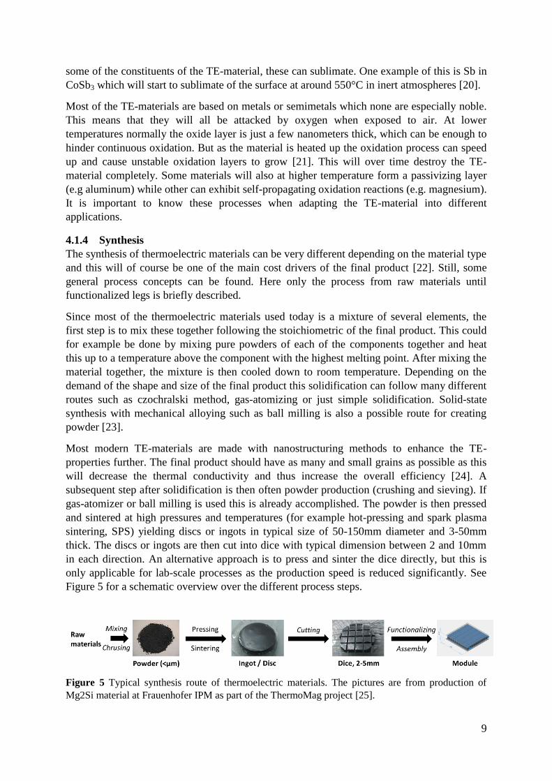
only applicable for lab-scale processes as the production speed is reduced significantly. See
Figure 5 for a schematic overview over the different process steps.
Figure 5 Typical synthesis route of thermoelectric materials. The pictures are from production of
Mg2Si material at Frauenhofer IPM as part of the ThermoMag project [25].
10
After the dice are cut into wanted geometry they are functionalized to lower contact
resistances and increase durability. This includes depositing thin layers of metal on both the
hot and cold side of the dice. Some technologies widely used are sputtering and electroplating
[26, 27]. The remaining four sides of the legs that will be exposed to the surrounding
atmosphere in some cases also need protecting in the form of coatings. These functionalized
legs can then be directly assembled into a module. This assembly process is not described any
further here as it is very dependent on the module design and temperature regime of the
application environment.
4.1.5 Abundance
The raw materials used in thermoelectric materials can be taken from nearly the whole
periodic system of elements and must be taken into consideration when evaluating the
scalability of the thermoelectric material especially for mass production processes. The
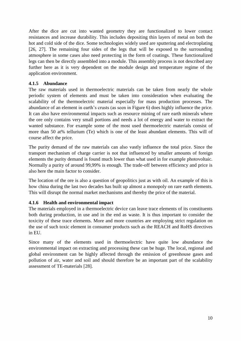
abundance of an element in earth’s crusts (as seen in Figure 6) does highly influence the price.
It can also have environmental impacts such as resource mining of rare earth minerals where
the ore only contains very small portions and needs a lot of energy and water to extract the
wanted substance. For example some of the most used thermoelectric materials consist of
more than 50 at% tellurium (Te) which is one of the least abundant elements. This will of
course affect the price.
The purity demand of the raw materials can also vastly influence the total price. Since the
transport mechanism of charge carrier is not that influenced by smaller amounts of foreign
elements the purity demand is found much lower than what used in for example photovoltaic.
Normally a purity of around 99,99% is enough. The trade-off between efficiency and price is
also here the main factor to consider.
The location of the ore is also a question of geopolitics just as with oil. An example of this is
how china during the last two decades has built up almost a monopoly on rare earth elements.
This will disrupt the normal market mechanisms and thereby the price of the material.
4.1.6 Health and environmental impact
The materials employed in a thermoelectric device can leave trace elements of its constituents
both during production, in use and in the end as waste. It is thus important to consider the
toxicity of these trace elements. More and more countries are employing strict regulation on
the use of such toxic element in consumer products such as the REACH and RoHS directives
in EU.
Since many of the elements used in thermoelectric have quite low abundance the
environmental impact on extracting and processing these can be huge. The local, regional and
global environment can be highly affected through the emission of greenhouse gases and
pollution of air, water and soil and should therefore be an important part of the scalability
assessment of TE-materials [28].
11
Figure 6 Abundance of the elements in the earth's crust, courtesy of the U.S. Geological Survey
4.2 STATE-OF-THE-ART MATERIALS The most used materials today are still based on formulas developed in the 1950s and 60s.
These materials were basically found when alloying semiconducting materials with
isomorphous elements or compounds. To reduce the lattice thermal conductivity they were
also heavily doped. Since all the thermoelectric properties of the material is dependent on
temperature they are usually divided into three different groups5; low temperature below
200°C, medium temperature between 200°C and 600°C and high temperature above 600°C
[11]. Typical ZT values as a function of temperature are found in Figure 4 and Figure 11.
4.2.1 Low temperature, < 200°C
The most common materials found in this temperature range are Bi2Te3 and Sb2Te3 solid
solutions [29]. The mixing of these two compounds will introduce some variations in the
mass on the anionic lattice position in the crystal leading to phonon scattering and thus
decreased thermal conductivity. The best bismuth telluride based materials used today have
ZT values up to 1.5 [30].
Bismuth telluride will vaporize above 400°C according to the reaction Bi2Te3 2BiTe(g) +
1/2Te2(g) which limits the use up to 300°C.
4.2.2 Medium temperature, 200 – 600°C
The group IV-tellurides, PbTe, GeTe and SeTe, are the most common materials in this
temperature range. Both n and p type materials can be made. The most used p-type is also
called TAGS, short for (GeTe)0.85(AgSbTe2)0.15, with a ZT of up to 1.2. For n-type materials
5 There is no clear definition on the temperature regimes thus the temperature values can vary with up to 100°C
depending on the source.
12
the normal ZT is a bit below 1 but high ZT values of 2.2 at 915K have been reached by using
nanostructuring methods. Both addition of SrTe nanoparticles dispersed in the crystal and
mesostructuring of the crystal grains using powder processing techniques where used to
achieve these high ZT values [31].
4.2.3 High temperature, > 600°C
At high temperatures the most frequently used TE-materials are Silicon-germanium alloys.
These have successfully been used for several long term space mission such as Voyager 1 and
2. Still, they have very high thermal conductivity because of diamond structure which
imposes limitation to the maximum ZT value. So far there has been no success of getting ZT
values more than 1. Because of this limitation on efficiency (especially on the lower side of
the temperature range), in addition to complication production processes and the relatively
expensive raw materials, these material are not adequate for terrestrial application such as
waste heat recovery.
4.3 NEW MATERIALS The search for new TE-materials can roughly be divided into two groups: increasing the
powerfactor, S2σ, or decrease the lattice thermal conductivity, ρph. The first approach was the
most frequently used in the early age of semiconductors while the second has gotten more and
more attention the last decades. Some general rules to follow when looking for new
thermoelectric materials where formulated by Slack [32] and focuses on the increase of the
ZT value.
Reduction of the lattice thermal conductivity,
High carrier mobility, µ
The density of state effective mass m* should be equal to the free electron mass m0
The bandgap energy, Eg, should be equal or higher than 0.25 eV
µ, amd m* are independent of the charge carrier concentration n, and and m*
are independent of temperature
The characteristic these rules imply is often summarized as a Phonon Glass, Electron Crystal
(PGEC) material. These are materials with very low lattice thermal conductivity similar to
amorphous materials, but still have electric properties like a crystalline material. Examples of
these types of materials are skutterudites and clathrates and will be furthered treated below.
Another way to decouple the thermal and electrical conductivity is to use nanostructuring
techniques in the production of the material as mentioned in section 4.1.4. Several reviews on
nano-engineered thermoelectric materials have been published the last couple of years and
also forms the base of the selection of materials below [16, 24, 31, 33].
4.3.1 Skutterudites
The name skutterudite stems from Skuterudåsen in Modum, Norway. It was there in the
middle of the 18th
century that the cobalt rich mineral where first discovered. This discovery
led to the construction of, at that time, one of Norway’s largest industrial sites where the ore
was extracted to produce distinct cobalt-blue color pigments for the porcelain industry [34].
But the thermoelectric properties of skutterudite were not recognized until relatively recent
times. In 1996 filled skutterudites were proposed as a new thermoelectric material which
could reach ZT values up to 1.4 [35]. Later it has been demonstrated even higher ZT values,
13
up to 1.7 at 850K [36]. The general formula of skutterudites is MX3 where M is a group IX
transition metal and X a nonmetallic atom. The most promising of these which have received
most attention is CoSb3 [37].
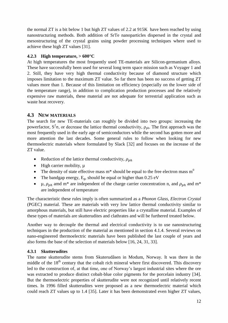
A look at the unit cell of skutterudite seen in Figure 7 offers some explanation for its good
thermoelectric properties. The inherent void in the structure between the octahedron formed
by the nonmetallic atoms can be filled with foreign elements which will act as rattlers atoms
decreasing the group velocity of the phonons and thus the lattice thermal conductivity. The
filler atoms are typically either lanthanides, actinides, alkali earth and even some elements
from the boron and carbon groups. The optimum filler atoms will also act as a dopant
increasing both the Seebeck coefficient and the electrical conductivity. The filler amount is
typically 0.5-2 at%. The sublimation oxidation of skutterudite above 380°C and the
sublimation of Sb above 550°C limits the use of skutterudite to enclosed environments. The
materials should therefore ideally be coated or kept in inert atmospheres during usage to avoid
degradation over time.
Figure 7 Schematic drawing of a filled skutterudite crystal structure. The pnicogen lattice position is
where the non-metallic element is positioned, forming an octahedron around the transition metal atom.
In the voids between the octahedron, filler atoms can be inserted to enhance thermoelectric properties.
Picture from [37].
4.3.2 Clathrates
Clathrate comes from the latin word clatratus which means encaged, and are an example of
PGEC material. The general formula is AxByC46-y where B and C are tetrahedrally bonded
forming a rigid framework of cages which encloses guest metal atoms, A, like seen in Figure
8. The metal atoms in the voids will act as barriers to phonon transport through the materials
thus yielding a very low thermal conductivity. There exist a wide variety of clathrates

14
structures and these are divided into nine different groups (I-IX) depending on the cage
structure, space group and intermetallic representatives [38].
The guest atoms will cause disturbances in the lattice disrupting phonon movement and
suppress the thermal conductivity. To increase the thermoelectric efficiency further, dopants
are introduced such as Ga on the framework sites. The amount of compounds used to make
clathrates can be large and the demand on purity of raw materials is high to ensure correct
phases to form during synthesis. The complexity of the production process will of course be a
hinder when considering mass production of the material [39].
Figure 8 Crystal structure of type-I clathrate compounds with general formula AxByC46-y [33]. The
metal atom, A, is enclosed in cages formed by the tetrahedrally bonded B and C atoms in the X sites.
4.3.3 Mg2BIV
solid solutions
These materials where tested already in the early 60s but was largely left undeveloped for
many decades. It has gotten renewed attention lately as it has a good potential as a cheap and
environmental friendly TE-material. The density is also very low (around 3 g/cm3) which is
important in vehicle applications.
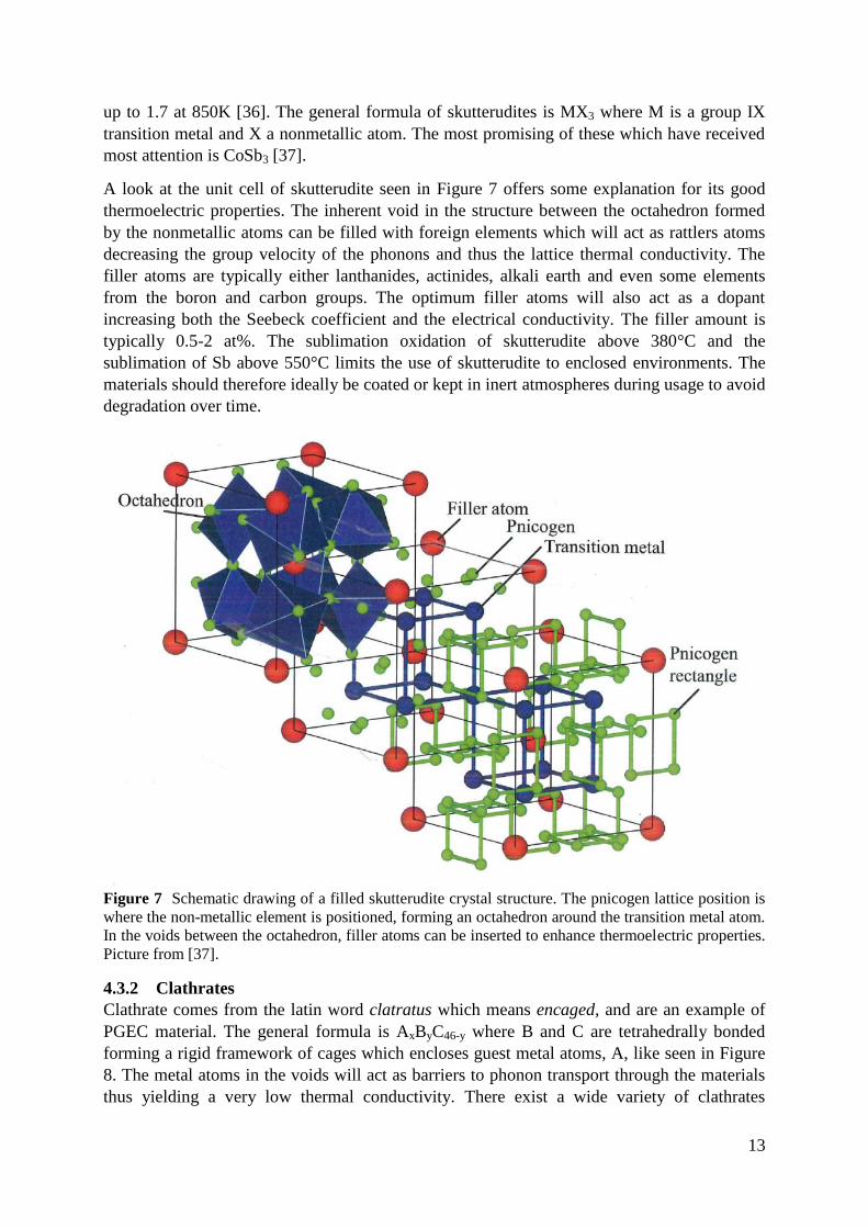
The general chemical formula is Mg2BIV
where BIV
can be either Si, Sn, or Ge, and the crystal
structure is that of CaF2 as seen in Figure 9. When these compounds are mixed as solid
solutions, as seen in the phase diagram in Figure 9, it can increase the TE-properties
dramatically. The difference in mass between the BIV
components introduces effective
phonon scattering centers. The best ZT value of 1.1 has been reached for Mg2Si0.6Sn0.4 [40].
The ZT curve for Mg2Si0.4Sn0.6 can be found in Figure 12.
15
Figure 9 Left: Crystal structure of Mg2BIV
compounds, where B = Si, Sn or Ge [41]. Right: Phase
diagram of Mg2Si and Mg2Sn and its solid solutions [42].
4.3.4 Silicides
The silicides are an interesting material group for thermoelectric power generation as they not
only show good thermoelectric properties, but also make use of cheaper raw materials and
offers good mechanical and chemical stability [43, 44].
Higher manganese silicide (HMS, MnSix, x=1.70-1.77) is the most promising TE-material of
the silicide group. It is an example of material with complex and large crystal structure. This
often leads to an amorphous behavior of the lattice part of the thermal conductivity as the
phonons are scattered effectively by the large distance between atoms. The c-axis of the
crystal structure is more than three times the length of the perpendicular axes leading to a
strong anisotropy of the crystal and thus also on the thermoelectric and mechanical properties.
The ZT curve of a HMS material is found in Figure 12.
Chromium disilicide, CrSi2, is another interesting silicide material. It has a hexagonal crystal
structure similar to HMS, but has still not been made with higher ZT values than
approximately 0.3. Other types of silicide are FeSi2, Ru2Si3 and CoSi.
4.3.5 Half-Heussler compounds
Half-heussler compounds are the more environmentally friendly version of PbTe. The general
chemical formula is ABX; a simple rock salt crystal formed by A and X and filled with B.
Example of these are MgAgAs and ZrNiSn. They have high Seebeck coefficient and electrical
conductivity, but also quite high thermal conductivity. This has somewhat been overcome by
introducing nano-scale composites in the structure and increasing the phonon scattering on the
boundaries. ZT values of up to 1.5 have been reported [45]. Another benefit of these materials
is its relatively high temperature stability.
4.3.6 Oxides
The most obvious benefit of an oxide TE-material is its thermal stability and oxidation
resistance at high temperatures, along with very low thermal conductivity. On the other hand
it has inherently also very low electrical conductivity and was thus ignored as a candidate for
TE for long time. This was changed when NaCo2O4-like oxides where discovered that showed
very promising TE-properties. This has spurred the research on even more oxide materials in
the last decades. The reason for the good TE properties of NaCo2O4 has its roots in its
16
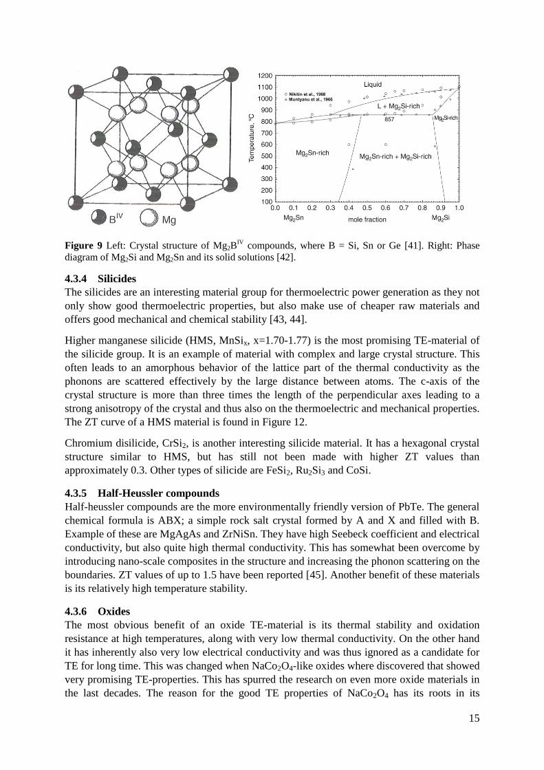
nanoblock crystal structure as seen in Figure 10, with alternating layers of CoO2 and
disordered Na atoms. The CoO2 layers act effectively as good electron conductors while the
sodium layer disturbs phonon transport through the matrix. ZT values of up to 0.8 have been
reported. Another interesting oxide group is that based on Ca-Co-O. These materials have
similar layered crystal structure as for NaCo2O4. Other types of oxides which are under
investigation are STiO3 and ZnO.
Figure 10 Crystal structure of NaCo2O4. The inherent nanoblock strucutre of the crystal lattice
enhances the electrical conductivity a lot compared to other oxide materials [24].
4.3.7 Zn4Sb3
Another very good material is Zn4Sb3. This is a p-type material with reported ZT values up to
1.3, because of its very low thermal conductivity similar to that of glass. The material is on
the other hand limited by its instability at higher temperatures. Already at 250°C it starts to
decompose both in oxidizing and inert atmospheres [46]. If good coating and encapsulation
techniques can be developed it is believed that this material can be used for commercial
applications up to at least 400°C.
17
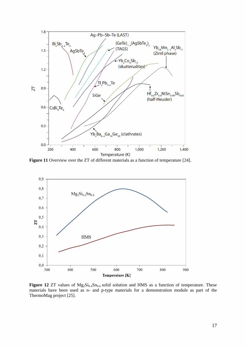
Figure 11 Overview over the ZT of different materials as a function of temperature [24].
Figure 12 ZT values of Mg2Si0.4Sn0.6 solid solution and HMS as a function of temperature. These
materials have been used as n- and p-type materials for a demonstration module as part of the
ThermoMag project [25].
18
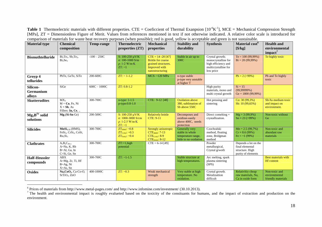
Table 1 Thermoelectric materials with different properties. CTE = Coeficcient of Thermal Exanpsion [10-6
K-1
], MCE = Mechanical Compression Strength
[MPa], ZT = Dimensionless Figure of Merit. Values from references mentioned in text if not otherwise indicated. A relative color scale is introduced for
comparison of materials for waste heat recovery purposes (when possible); red is good, yellow is acceptable and green is not sustainable. Material type Chemical
composition
Temp-range Thermelectric
properties (ZT)
Mechanical
properties
Stability and
durability
Synthesis Material cost6
[$/kg]
Health and
environmental
impact7
Bismuthtelluride Bi2Te3, Sb2Te3,
Bi2Se3
-100 – 250C S: 100-250 µV/K
σ: 100-1000 S/m
ρ: 1-2 W/m∙K
ZT: ~1
CTE = 14 -20 [47]
Brittle for coarse
grained structures.
Improved with
nanostructuring
Stable in air up to
300C
Crystal growth;
monocrystalline for
high efficiency and
multicrystalline for
low price
Te = 100 (99,99%)
Bi = 20 (99,99%)
Te highly toxic
Groyp 4
tellurides
PbTe, GeTe, SiTe 200-600C ZT: ~ 1-1.2 MCS: ~120 MPa n-type stable
p-type very unstable
at higher T
Pb = 2 (>99%) Pb and Te highly
toxic
Silicon-
Germanium
alloys
SiGe 600C – 1000C ZT: 0.8-1.2 High purity
materials, mono and
multi crystal growth
Si = 15
(99,99999%)
Ge = 1800 (99,99%)
Skutterudites MX3
M = Co, Fe, Ni
X = Sb, As
Fillers: In, Ce, ..
300-700C n-type: 1-1.5
p-type:0.8-1.0
CTE: 9-12 [48] Oxidation above
380, sublimation of
Sb above 550C
Hot pressing and
sintering
Co: 30 (99,3%)
Sb: 10 (99,65%)
Sb/As medium toxic
and impact on
environment.
Mg2BIV
solid
solutions
Mg2(Si-Sn-Ge) 200-500C S: 100-250 µV/K
σ: 1000-3000 S/cm
ρ: 1-2.5 W/m∙K ZT: ~1
Relatively brittle
CTE: 9-11
Decomposes and
oxidizes easily
above 400C, needs protection
Direct comelting +
crystallization.
Mg = 3 (99,9%)
Sn = 23 (>99%)
Non-toxic without
Ge
Silicides MnSi1,72 (HMS),
FeSi2, CrSi2, CoSi,
Ru2Si3
300-700C ZTHMS: ~0.8
ZTCrSi2: ~0.3
ZTFeSi2: ~0.4
Strongly anisotropic
CTEHMS: 7-13
CTECrSi2: 8-9 CTEFeSi2: 8-12
Generally very
stable in whole
temperature range, little to no oxidation
Czochralski
method, floating
zone, Bridgman method
Mn = 2.5 (99,7%)
Cr = 8.6 (99%)
Fe = ~1 (99%)
Non-toxic and
abundant raw
materials
Clathrates AxByC46-y
A=Na, K, Rb B=Al, Ga, In
C=Si, Ge, Sn
300-700C ZT:>1,high
potential
CTE = 6-14 [49] Powder
metallurgical, Crystal grwoth
Depends a lot on the
final elemental structure. High
purity of elements
Half-Heussler
compounds
ABX A=Mg, Zr, Ti, Hf
B=Ag, Ni
X=As, Sn
300-700C ZT: ~1-1.5 Stable structure at high temperatures.
Arc melting, spark plasma sintering
(SPS)
Best materials with Hf content
Oxides NaxCoO2, Ca-Co-O, SrTiO3, ZnO
400-1000C ZT: ~0.3 Weak mechanical strength
Very stable at high temperature. No
oxidation.
Crystal growth. Metalizattion
difficult
Relativltiy cheap raw materials, Na,
Ca in oxide form
Non-toxic and environmental
friendly materials
6 Prices of materials from http://www.metal-pages.com/ and http://www.infomine.com/investment/ (30.10.2013).
7 The health and environmental impact is roughly evalueted based on the toxicity of the consituants for humans, and the impact of extraction and production on the
environment.
19
5 SUMMARY AND CONCLUSION
Waste heat recovery is one of the best ways to handle future increase in energy demand. Up to
now most attention has been given to recovery of high temperature and volume waste heat
sources as this has best payback times in terms of investment. But the potential is still huge,
though new technologies are needed to spur the investment in exploiting more of this
enormous energy potential. In this report it has been shown how thermoelectric energy
conversion is a good candidate for many waste heat recovery applications such as exhaust
heat in a vehicle which otherwise is lost to the environment. Thermoelectric power generation
is a solid state technology with no moving parts and easily scalable to any size. It can also be
used over a broad temperature range. But to implement this technology in waste heat recovery
applications, more effort is needed in the search for more efficient materials which can be
produced at a low enough prices. It should also be made of non-toxic and sustainable
materials. Especially the strong demand for more fuel-efficient vehicles has led almost all the
major car industry players to invest in research on thermoelectric waste heat recovery.
Today there exist a wide variety of different promising thermoelectric materials as a result of
a strong growth in research in the field the last two decades. Many of these materials have
now reached a point in the development phase where they are ready to enter mass-production
processes. Some of the most promising candidates which are believed to enter the market on a
larger scale the next decades have been described, and a summary of their potential can be
found in Table 1.
Skutterudite has already pinpointed itself as the material which will be the first to enter the
market on an industrial scale and several projects is ongoing to start pilot-scale production
and further explore industrial opportunities8. Skutterudite is made of relatively cheap raw
materials and the synthesis can easily be scaled up with well-known production technology.
The strong pull from the car-industry will probably make thermoelectric generators made with
this type of material a common sight in cars in just 3-5 years.
Magnesium silicide based materials are believed to be a very good candidate for the next
generation thermoelectric materials for waste heat recovery in cars. Magnesium silicide is
made of abundant and non-toxic raw materials with a large and stable material supply chain
already existing. They are also very lightweight which is important for the use in the transport
sector. Unfortunately they are now somewhat limited by the instability at higher temperatures
but this can be solved by developing good coating and encapsulation techniques.
Other materials such as clathrates, half-heussler compounds, silicides and oxides can all be
part of a thermoelectric future, but it is very dependent on the possibility to produce them in a
cost efficient manner. New and better technologies in nanostructuring will probably cause
even higher ZT values to be found in the future, but if the synthesis is to complex it will only
be applicable for niche application and not a candidate for waste heat recovery on a larger
scale.
8 One of them, TEGma, is a partner of UiA in a project on developing the process of mass-production of this
material, while TermoMag is another EU-funded project to explore the possibility of using magnesium silicide
and developing the process further for industrial applications.
20
REFERENCES
1. IEA, World Energy Outlook. 2012.
2. BP, BP Energy Outlook 2030, 2012: London.
3. Library, L.L.N. U.S. Energy Flow. 2012 [cited 2013 25. October]; Available from:
https://flowcharts.llnl.gov/energy.html#2012.
4. Yang, J. and F. Stabler, Automotive Applications of Thermoelectric Materials. Journal of Electronic
Materials, 2009. 38(7): p. 1245-1251.
5. Energi, N. and NEPAS, Potensialstudie for utnyttelse av spillvarme fra norsk industri, 2009, Enova.
6. Enova. Enova støtter storsatsing på energigjenvinning ved Elkem Salten. 2013 [cited 2013 31.10];
Available from: http://www.enova.no/finansiering/naring/aktuelt/enova-stotter-storsatsing-pa-
energigjenvinning-ved-elkem-salten/250/975/.
7. EERE, Waste Heat Recovery: Technology and Opportunities in U.S. Industry, 2009, EERE.
8. Rowe, D.M., Thermoelectric Waste Heat Recovery as a Renewable Energy Source. International
Journal of Innovations in Energy Systems and Power, 2006. 1(1).
9. Zervos, H., Thermoelectric Energy Harvesting 2013-2023: Devices, Applications, Opportunities, 2013,
IDTechEx.
10. Rowe, D.M., Introduction, in CRC Handbook of Thermoelectrics, D.M. Rowe, Editor. 1995, CRC Press,
Tylor & Francis group: Boca Raton, Florida.
11. Snyder, G.J. and E.S. Toberer, Complex thermoelectric materials. Nature Materials, 2008. 7(2): p. 105.
12. Rowe, D.M., General principles and conciderations, in Thermoelectrics Handbook, Macro to Nano,
D.M. Rowe, Editor. 2006, CRC Press, Tylor & Francis group: Boca Raton, Florida. p. 1-13.
13. Abelson, R.D., Space Missions and Applications, in Thermoelectrics Handbook, Macro to Nano, D.M.
Rowe, Editor. 2006, CRC Press, Tylor & Francis group: Boca Raton, Florida.
14. Hicks, L.D. and M.S. Dresselhaus, Effect of quantum-well structures on the thermoelectric figure of
merit. Physical Review B, 1993. 47(19): p. 12727-12731.
15. Hicks, L.D. and M.S. Dresselhaus, Thermoelectric figure of merit of a one-dimensional conductor.
Physical Review B, 1993. 47(24): p. 16631-16634.
16. Martín-González, M., O. Caballero-Calero, and P. Díaz-Chao, Nanoengineering thermoelectrics for
21st century: Energy harvesting and other trends in the field. Renewable and Sustainable Energy
Reviews, 2013. 24(0): p. 288-305.
17. Goldsmid, H.J., Thermoelectric Properties of Metals and Semiconductors, in Introduction to
Thermoelectricity, H.J. Goldsmid, Editor. 2009, Springer. p. 23-41.
18. ThermoMag, D1.1 End-User Design Requirements, 2011, ESA. p. 44.
19. Engineering Toolbox: Coefficients of Linear Thermal Expansion. [cited 2013 4. November]; Available
from: http://www.engineeringtoolbox.com/linear-expansion-coefficients-d_95.html.
20. Zhao, D., et al., High temperature sublimation behavior of antimony in CoSb3 thermoelectric material
during thermal duration test. Journal of Alloys and Compounds, 2011. 509(6): p. 3166-3171.
21. Evans, U.R., The corrosion and oxidation of metals: Scientific Principles and Practical Applications.
1960: St. Martin's Press.
22. Belov, Y.M., S.M. Maniakin, and I.V. Morgunov, Review of Methods of Thermoelectric Materials Mass
Production, in Thermoelectrics Handbook, Macro to Nano, D.M. Rowe, Editor. 2006, CRC Press,
Tylor & Francis group: Boca Raton, Florida.
23. Book, B.A. and J.L. Harringa, Solid-State Synthesis of Thermoelectric Materials, in Thermoelectrics
Handbook, Macro to Nano, D.M. Rowe, Editor. 2006, CRC Press, Tylor & Francis group: Boca Raton,
Florida.
24. Li, J.-F., et al., High-performance nanostructured thermoelectric materials. NPG Asia Mater, 2010. 2:
p. 152-158.
25. ThermoMag, Final description of Work, in Seventh Framework Program NMP-2010-1.2-3 2010.
26. Li, X., et al. Mo/Ti/CoSb3 joining technology for CoSb3 based materials. in Thermoelectrics, 2005. ICT
2005. 24th International Conference on. 2005.
27. Schlesinger, M. and M. Paunovic, Modern Electroplating. 2011: Wiley.
28. UNEP, Assessing the environmental impacts of consumption and production: Priority Products and
Materials, A Report of the Working Group on the Environmental Impacts of Products and Materials to
the International Panel for Sustainable Resource Management., Hertwich, E., van der Voet, E., Suh, S.,
Tukker, A., Huijbregts M., Kazmierczyk, P., Lenzen, M., McNeely, J., Moriguchi, Y, Editor 2010.
29. Scherrer, H. and S. Scherrer, Thermoelectric Properties of Bismuth Antimony Telluride Solid Solutions,
in Thermoelectrics Handbook, Macro to Nano, D.M. Rowe, Editor. 2006, CRC Press, Tylor & Francis
group: Boca Raton, Florida.
21
30. Xie, W., et al., Unique nanostructures and enhanced thermoelectric performance of melt-spun BiSbTe
alloys. Applied Physics Letters, 2009. 94(10): p. 102111-102111-3.
31. Biswas, K., et al., High-performance bulk thermoelectrics with all-scale hierarchical architectures.
Nature, 2012. 489(7416): p. 414-418.
32. Slack, G.A., New Materials and Performance Limits for Thermoelectric Cooling, in CRC Handbook of
Thermoelectrics, D.M. Rowe, Editor. 1995, CRC Press, Tylor & Francis group: Boca Raton, Florida.
33. Alam, H. and S. Ramakrishna, A review on the enhancement of figure of merit from bulk to nano-
thermoelectric materials. Nano Energy, 2013. 2(2): p. 190-212.
34. Liessmann, W., Der Bergbau und die Mineralien von Modum-Skutreud, Norwegen, in Emser Hefte1994,
Doris Bode Verlag GMBH: Haltern, Germany.
35. Sales, B.C., D. Mandrus, and R.K. Williams, Filled Skutterudite Antimonides: A New Class of
Thermoelectric Materials. Science, 1996. 272(5266): p. 1325-1328.
36. Shi, X., et al., Multiple-Filled Skutterudites: High Thermoelectric Figure of Merit through Separately
Optimizing Electrical and Thermal Transports. Journal of the American Chemical Society, 2011.
133(20): p. 7837-7846.
37. Sesselmann, A.J., Investigation on the Thermoelectric and Structural Properties of Cobalt-Antimony
based Skutterudites and Modifications with Indium and Rare-Earth Elements, 2012, Universität
Augsburg.
38. Rogl, P., Formation and Crystal Chermistry of Clathrates, in Thermoelectrics Handbook, Macro to
Nano, D.M. Rowe, Editor. 2006, CRC Press, Tylor & Francis group: Boca Raton, Florida.
39. Nolas, G.S., Structure, Thermal Conductivity, and Thermoelectric Properties of Clathrate Compounds,
in Thermoelectrics Handbook, Macro to Nano, D.M. Rowe, Editor. 2006, CRC Press, Tylor & Francis
group: Boca Raton, Florida.
40. Zaitsev, V.K., et al., Highly effective Mg2Si1−xSnx thermoelectrics. Physical Review B, 2006. 74(4): p.
045207.
41. Zaitsev, V.K., et al., Thermoelectrics on the Base of Solid Solutions of Mg2BIV
Compounds (B V = Si, Ge,
Sn), in Thermoelectrics Handbook, Macro to Nano, D.M. Rowe, Editor. 2006, CRC Press: Boca Raton,
Florida. p. 1-11.
42. Jung, I.-H., et al., Thermodynamic modeling of the Mg–Si–Sn system. Calphad, 2007. 31(2): p. 192-200.
43. Fedorov, M.I. and V.K. Zaitsev, Thermoelectrics of Transition Metal Silicides, in Thermoelectrics
Handbook, Macro to Nano, D.M. Rowe, Editor. 2006, CRC Press, Tylor & Francis group: Boca Raton,
Florida.
44. Fedorov, M.I., Thermoelectric Silicides: Past, Present and Future. Journal of Thermoelectricity, 2009.
2: p. 51-60.
45. Sakurada, S. and N. Shutoh, Effect of Ti substitution on the thermoelectric properties of (Zr,Hf)NiSn
half-Heusler compounds. Applied Physics Letters, 2005. 86(8): p. -.
46. Yin, H., et al., Thermal Stability of Thermoelectric Zn4Sb3. Journal of Electronic Materials, 2010. 39(9):
p. 1957-1959.
47. Pavlova, L.M., Y.I. Shtern, and R.E. Mironov, Thermal expansion of bismuth telluride. High
Temperature, 2011. 49(3): p. 369-379.
48. Rogl, G., et al., Thermal expansion of skutterudites. Journal of Applied Physics, 2010. 107(4): p.
043507-10.
49. Falmbigl, M., et al., Thermal expansion of thermoelectric type-I-clathrates. Journal of Applied Physics,
2010. 108(4): p. 043529-35299.
Related Documents


![[Recovery] Cwm Recovery 6.0.3](https://static.cupdf.com/doc/110x72/55cf9443550346f57ba0c2b8/recovery-cwm-recovery-603.jpg)