archives of thermodynamics Vol. 41(2020), No. 1, 95–123 DOI: 10.24425/ather.2020.132951 Thermodynamic analysis of a combined cycle power plant located in Jordan: A case study KHALED BATAINEH ∗ BARA A. KHALEEL Jordan University of Science and Technology, P O Box 3030 Irbid, 22110, Jordan Abstract Efficiency and electrical power output of combined cycle power plants vary according to the ambient conditions. The amount of these vari- ations greatly affects electricity production, fuel consumption, and plant incomes. Obviously, many world countries have a wide range of climatic conditions, which impact the performance of power plants. In this paper, a thermodynamic analysis of an operating power plant located in Jordan is performed with actual operating data acquired from the power plant control unit. The analysis is performed by using first and second laws of thermo- dynamics. Energy and exergy efficiencies of each component of the power plant system are calculated and the effect of ambient temperature on the components performance is studied. The effects of gas turbine pressure ratio, gas turbine inlet temperature, load and ambient conditions on the combined cycle efficiency, power outputs and exergy destruction are investi- gated. Energy and exergy efficiencies of the combined cycle power plant are found as 45.29%, and 42.73% respectively when the ambient temperature is 34 ◦ C. Furthermore, it is found that the combustion chamber has the largest exergy destruction rate among the system components. The results showed that 73% of the total exergy destruction occurs in the combustion chamber when the ambient temperature is 34 ◦ C. Moreover, the results show that the second major exergy loss is in HRSC. The results show that the energy and exergy efficiency of the combined cycle power plant decreases as the ambient temperature increases. According to the calculation results, improvement and modification suggestions are presented. Keywords: Combined cycle power plant; Energy efficiency; Exergy efficiency; Exergy destruction; Exergy losses ∗ Corresponding Author: Email: [email protected]

Welcome message from author
This document is posted to help you gain knowledge. Please leave a comment to let me know what you think about it! Share it to your friends and learn new things together.
Transcript
archivesof thermodynamics
Vol. 41(2020), No. 1, 95–123
DOI: 10.24425/ather.2020.132951
Thermodynamic analysis of a combined cycle
power plant located in Jordan: A case study
KHALED BATAINEH ∗
BARA A. KHALEEL
Jordan University of Science and Technology, P O Box 3030 Irbid, 22110,Jordan
Abstract Efficiency and electrical power output of combined cycle powerplants vary according to the ambient conditions. The amount of these vari-ations greatly affects electricity production, fuel consumption, and plantincomes. Obviously, many world countries have a wide range of climaticconditions, which impact the performance of power plants. In this paper,a thermodynamic analysis of an operating power plant located in Jordan isperformed with actual operating data acquired from the power plant controlunit. The analysis is performed by using first and second laws of thermo-dynamics. Energy and exergy efficiencies of each component of the powerplant system are calculated and the effect of ambient temperature on thecomponents performance is studied. The effects of gas turbine pressureratio, gas turbine inlet temperature, load and ambient conditions on thecombined cycle efficiency, power outputs and exergy destruction are investi-gated. Energy and exergy efficiencies of the combined cycle power plant arefound as 45.29%, and 42.73% respectively when the ambient temperature is34 ◦C. Furthermore, it is found that the combustion chamber has the largestexergy destruction rate among the system components. The results showedthat 73% of the total exergy destruction occurs in the combustion chamberwhen the ambient temperature is 34 ◦C. Moreover, the results show that thesecond major exergy loss is in HRSC. The results show that the energy andexergy efficiency of the combined cycle power plant decreases as the ambienttemperature increases. According to the calculation results, improvementand modification suggestions are presented.
Keywords: Combined cycle power plant; Energy efficiency; Exergy efficiency; Exergydestruction; Exergy losses
∗Corresponding Author: Email: [email protected]
96 K. Bataineh, Bara A. Khaleel
Nomenclature
Cp – specific heat at constant pressure, kJ/kgKCV – specific heat at constant volume, kJ/kgK
E – energy rate, kWh – enthalpy, kJ/kgLHV – lower heating value, MJ/kgm – mass flow rate, kg/sP – pressure, bar
Q – heat flow, kWq – specific heat flow, kJ/kgR – gas constant, J/g Kr – pressure ratios – entropy, kJ/kgKT – temperature, ◦CW – work, kJW – power, kWw – specific work, kJ/kgX – exergy rate, kW
Greek symbols
η – efficiencyζ – fuel factorψ – specific exergy, kJ/kg
Subscripts
a – airCC – combustion chamberCCPP – combined cycle power plantdes – destructionf – fuelGT – gas turbineg – exhaust gasin – inletout – exito – dead stateSC – simple cycleST – steam turbine
Abbreviations
ACC – air cooled condenserCC – combustion chamber
Thermodynamic analysis of a combined cycle power plant. . . 97
CCPP – combined cycle power plantEc – economizerEvap – evaporatorex – exergyFW – feed waterGT – gas turbineHP – high pressureHRSG – heat recovery steam generatorIP – intermediate pressureLP – low pressureSC – simple cycleSH – super heaterST – steam turbineSEPCO – Samara Electric Power Companyth – thermal
1 Introduction
Gas turbines (based on the Brayton cycle) are increasingly used in combina-tion with steam turbines (based on the Rankine cycle), either to generateelectricity alone in combined cycles, or to produce in cogeneration bothelectrical power and heat for industrial processes [1]. A combined cyclefeaturing one or several gas turbines and a steam cycle is a power plantoption commonly used for power production that offers a high efficiency.Obviously, the combined power cycle plants play an important role in thepresent energy sector. This cycle has a higher thermal efficiency than eitherof the cycles executed individually so it is of greatest interest of all [2].
Generally, the performance of thermal power plants is evaluated throughenergy analysis based on the first law of thermodynamics, including thermalefficiency of the simple cycle and combined cycle. Energy efficiencies canbe non-intuitive or even deceptive [3]. Energy losses during the operationprocess can be large, and the amount of lost energy is thermodynamicallyuseless due to its low quality. Recently, the exergy analysis based on thesecond law of thermodynamics is used as a useful method in evaluationand improvement of the power plants. The exergy efficiencies and destruc-tion provide measures of approach to ideality. Such results allow unlimitedopportunities for improvements. Exergy analysis can determine the mag-nitude and location of losses in the power plants and within individualcomponents. Exergy analysis deals with the quality of energy but energyanalysis deals with quantity of energy. Therefore, complete system charac-teristics can be calculated using both energy and exergy analysis.
98 K. Bataineh, Bara A. Khaleel
Several studies are found in the literature that used the energy andexergy analysis of thermal power plants [1–25]. Moreover, most of thesestudies have focused on the performance analysis and performance enhance-ment of the combined cycle power plant (CCPP) using various technologies.Ibrahim et al. presented a review of the latest thermodynamics analysisof each system components of a CCPP independently and determine theexergy destruction of the plant [4]. They found that most of energy lossesoccurred in the condenser, while the highest exergy destruction occurred inthe combustion chamber (CC). Moreover, based on the review, it was foundthat the increasing ambient temperature causes an evident decrease in thepower production by the gas turbine. Finally, they proved that both energyand exergy analyses should be used to enhance the performance of CCPP.Kakaras reported that the gas turbine output and efficiency is a strongfunction of the ambient air temperature [5]. He found that depending onthe gas turbine type, the power output is reduced between 5% and 10% ofthe ISO-rated power output (15 ◦C) for every 10 ◦C increase in ambientair temperature. Ersayin et al. studied the combined cycle power plantlocated in Turkey using the first and second laws of thermodynamics [6].Energy and exergy efficiencies of each component of the power plant systemwere investigated. Most of exergy destruction was found in the combustionchamber. Energy and exergy efficiencies of the combined cycle power plantwere found as 56% and 50.04% respectively. Petrakopoulou et al. ana-lyzed a combined cycle power plant using both conventional and advancedexergetic analyses [7]. It was found that 87% of the total exergy destruc-tion takes place within the combustion chamber component. Furthermore,about 68% of the total exergy destruction in the combustion chamber can-not be avoided (unavoidable exergy destruction). Almutairi et al. studiedan actual combined cycle power plant (CCPP) in Kuwait using energy andexergy analysis [8]. The plant has an advanced triple pressure reheat heatrecovery steam generator (HRSG). They used sensitivity analysis of HRSGto differentiate between the sources of irreversibility. Aljundi calculatedenergy and exergy losses of a steam power plant located in Jordan usingenergy and exergy analysis [9]. They found that the major exergy destruc-tion takes place in the boiler system where 77% of the fuel exergy inputto the cycle was destroyed. Srinivas et al. presented optimization analysisof the performance of CCPP with different types of HRSG having a singlepressure, dual pressure, and triple pressure reheat [10]. They found thatthe optimal HRSG configuration led to improvement in steam generation
Thermodynamic analysis of a combined cycle power plant. . . 99
and therefore, in the output of the steam turbine.The previous studies on combined cycle power plant have divided the
exergy into four main groups as: physical, chemical, kinetic and potentialexergy. The kinetic and potential exergy are found to be insignificant com-ponents through the analysis and were ignored. On the other hand, thephysical and chemical exergy were found to be significant components ofthe exergy through the analysis [11–14]. The chemical exergy of a substanceis the highest work available that can be obtained at standard conditionsat constant pressure and temperature (1 atm and 25 ◦C respectively) [15].Hence, the chemical exergy is considered the most important quantity in thecombustion process. Any deviations of the pressure and temperature fromthe standard conditions lead to the generation of the physical exergy [16].
Dhar Garg et al. evaluated the performance of a combined cycle co-generation configuration in India based on energy and exergy analysis ap-proaches [16]. They investigated the effect of operating conditions on com-bined cycle efficiency, power outputs, and exergy destruction. Woudstraet al. studied three different heat recovery steam generators (HRSG) [17].These HRSG systems are designed and modeled using the computer pro-gram called Cycle-Tempo. They found out that the highest losses in thegas turbine are caused by (thermal) combustion of fuel. Furthermore, thetriple pressure system has a higher efficiency when compared with a singlepressure system. This is due to the reduction of the exergy loss of heattransfer in HRSG. Bagdanavicius et al. found out that the combined cyclepower plant (CCPP) is the most exergy efficient system with the lowestexergy cost of electricity and heat produced [18].
Integrating vapor compression and vapor absorption cooling systems toa combined cycle plant for inlet air cooling is investigated by [19]. Theyfound that inlet air cooling can lead to an increase of the plant’s specificpower output by 9.02%. However, to operate the vapor compression sys-tem, power is extracted from the gas turbine output. Boonnasa et al.integrated a steam operated absorption chiller to a CCPP for the compres-sor inlet air cooling [20]. The gas turbine power output increased by about10.6%, though the power output of the steam turbine was decreased byabout 2.43% due to the steam extracted to operate the absorption chiller.Integration of a chilled-water thermal energy storage system to precool theinlet air of CCPP is proposed by [21,22]. The temperature of the thermalenergy storage system was maintained by an absorption refrigeration sys-tem powered by waste heat from the flue gases of CCPP. Although there is
100 K. Bataineh, Bara A. Khaleel
an improvement, a large volume of the storage tank limits the feasibly ofthis integration. Oko and Njoku investigated the performance of an exist-ing combined cycle power plant augmented with a waste heat fired organicRankine cycle power plant for extra power generation [23]. They found outthat exergy and energy efficiencies of the thermal power plant improved by1.95% and 1.93%, respectively.
In this work, energy and exergy analysis of actual power plant is per-formed with actual operating data acquired from the power plant controlunit. Moreover, the effect of seasonal operating conditions is studied. Theanalysis is performed by using the first and second laws of thermodynam-ics. Energy and exergy efficiencies of each component of the power plantsystem are calculated.
2 Power plant studied
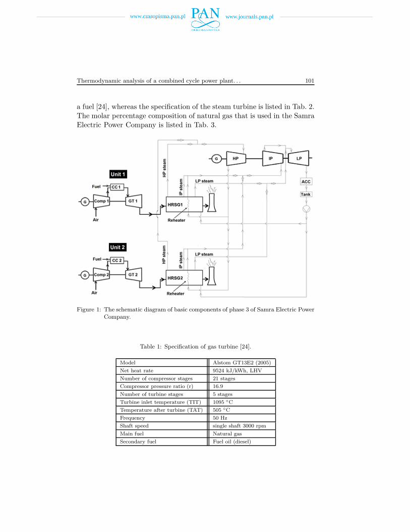
The basic components of phase 3 of the Samra Electric power plant consid-ered in this study are shown in Fig. 1. The actual operating data of a com-bined cycle power plant located in Jordan are considered in this study. Thepower plant has a total power capacity of 1100 MW, covering almost 40%of Jordan load. It has four phases: phase one, phase two, phase three andphase four. Phase three of the Samra Electric Power Company is stud-ied in this paper. Phase three of the plant has two Alstom gas turbineunits, two heat recovery steam generators (HRSG) and one Alstom steamturbine with total power about 430 MW. Fresh air at ambient conditionsenters into the compressor, where its pressure and temperature are raised.The compressed air enters into the combustion chamber and is burned withthe fuel. The high energy and enthalpy combustion gases expand in thegas turbine to produce power. The exhaust gases from the gas turbine canbe used as the energy source in the bottoming cycle. The energy from theexhaust gases is recovered by heat recovery steam generators to producesteam. The produced steam in HRSG enters into the steam turbine toproduce work, and to be finally cooled by an air cooled condenser.
The Samra Electric Power Company has two 142×2 MW gas turbinesand one 140 MW steam turbine. The combustion gases enter the gas tur-bines at 1095 ◦C and steam enters the steam turbine at three pressurelevels, high pressure (490 ◦C, 105.2 bar), intermediate pressure + reheat(480 ◦C, 21.5 bar) and low pressure (262 ◦C, 3.3 bar). The specificationof the gas turbine is listed in Tab. 1 at full load running on natural gas as
Thermodynamic analysis of a combined cycle power plant. . . 101
a fuel [24], whereas the specification of the steam turbine is listed in Tab. 2.The molar percentage composition of natural gas that is used in the SamraElectric Power Company is listed in Tab. 3.
Figure 1: The schematic diagram of basic components of phase 3 of Samra Electric PowerCompany.
Table 1: Specification of gas turbine [24].
Model Alstom GT13E2 (2005)
Net heat rate 9524 kJ/kWh, LHV
Number of compressor stages 21 stages
Compressor pressure ratio (r) 16.9
Number of turbine stages 5 stages
Turbine inlet temperature (TIT) 1095 ◦C
Temperature after turbine (TAT) 505 ◦C
Frequency 50 Hz
Shaft speed single shaft 3000 rpm
Main fuel Natural gas
Secondary fuel Fuel oil (diesel)
102 K. Bataineh, Bara A. Khaleel
Table 2: Specification of steam turbine [24].
Model Alstom
Nominal power 140 MW
Frequency 50 Hz
shaft speed single shaft 3000 rpm
HP steam Temperature & pressure 490 ◦C, 105.2 bar
IP + reheat steam Temperature & pressure 480 ◦C, 21.5 bar
LP steam Temperature & pressure 262 ◦C, 3.3 bar
air cooled condenser Temperature & pressure (ACC) 57.3 ◦C, 0.176 bar
Table 3: Natural gas composition.
Components Molar percentage
Methane 99.85%
Propane 0.07%
Nitrogen 0.08%
3 Thermodynamic analysis
Thermodynamic analyses of the thermal power plant are performed usingboth the first and second law of thermodynamics. The exergy analysis isbased on the second law of thermodynamics. There are two forms of energythat are transferred to or from a system: work W , and heat Q.
3.1 Energy analysis
Energy analysis for the combined cycle power plant was applied to twocycles; the Brayton cycle (top cycle) and the Rankine cycle (bottom cycle).The mass and energy conservation equations applied to a control volumeafter ignoring kinetic and potential energy are:
∑
min =∑
mout , (1)
Q− W =∑
mouthout −∑
minhin . (2)
Thermodynamic analysis of a combined cycle power plant. . . 103
The thermal efficiency of the Brayton cycle is given as
ηth,GT =Wnet,GT
Qccor ηth,GT =
wnet,GT
qcc. (3)
Thermal efficiencies of the combined cycle are given as
ηth,CCP P =Wnet,GT + W ST,net
Qcc. (4)
The power consumed by the compressor in the Brayton cycle is
Wcomp,in = ma(h2 − h1) = maCpa(T2 − T1) , (5)
where T 1 and T 2 are air temperatures at the inlet and outlet of the compres-sor, respectively. Cpa denotes the average specific heat of the air betweenT 1 and T 2, given as
Cpa(T ) = 1.04841 − 3.83719
104T +
9.45378
107T 2
− 9.45378
1010T 3 +
7.92981
1014T 4 . (6)
The mass conservation in the combustion chamber is
mg = ma + mf or m3 = m2 + m5 , (7)
where mg, ma, and mf denote the combustion gases flow rate (m3), airflow rate (m2) and fuel flow rate (m5), respectively. The heat supplied bythe combustion chamber is
Qcc = mf LHV , (8)
where LHV is the average lower heat value for the natural gas. The gener-ated power by the gas turbine is
WGT,out = m4(h3 − h4) = mgCpg(T3 − T4) , (9)
where T 3 and T 4 are air temperatures at the inlet and outlet of the turbine,respectively. Cpg denotes the average specific heat of the combustion gasesbetween T 3 and T 4 given as [25]
Cpg(T ) = 0.991615 − 6.99703
105T +
2.7129
107T 2 − 1.22442
1010T 3 . (10)
104 K. Bataineh, Bara A. Khaleel
The net generated power by the simple cycle is
Wnet,GT = WGT,out − Wcomp,in . (11)
The heat recovered by HRSG (water cycle side) is given by
QHRSG = m19(h19 − h16) + m10(h10 − h16) + m10(h15 − h10)
+ m6(h6 − h16) + m9(h9 − h6) + (m14 − m13)(h15 − h21). (12)
The specific heat recovered by HRSG (exhaust gas from the gas turbine)is given as
qHRSG = Cp(THRSH,in − THRSH,out) = Cp(T4 − THRSH,out) , (13)
where Cp is the specific heat averaged between the temperature at theHRSG inlet and outlet. The mass flow rate of gases in HRSG and gasturbine is
mg =QHRSG
qHRSG. (14)
The generated power by the steam turbine is
WST,out = m20h20 − m21h21 + m22h22 + m23h23 − m24h24 . (15)
The net generated power by the Rankine cycle can be found as
W ST,net = W ST,out − W cons , (16)
where the consumed power is
Wcons = WF W pump,in+Wcondensate.pump,in+WACC+Wauxiliary.system . (17)
4 Exergy analysis
Exergy represents the upper limit of the amount of work a device can deliverwithout violating any thermodynamic laws [1]. In other words, exergy is themaximum useful work that can be obtained from the system at a given statein a specified environment. Exergy destruction is the wasted work during aprocess between two specified states. Reversible work of the turbine is themaximum work output at the minimum work of the pump and compressor.This can be achieved when exergy destruction of the components equalszero. In this study, potential and kinetic exergy are neglected, physical and
Thermodynamic analysis of a combined cycle power plant. . . 105
chemical exergy are included for each component in the combined cyclepower plant. In the combined cycle power plant, exergy is transferred bywork, heat and mass flow. Exergy transfer by work is
Xwork = W . (18)
Exergy transfer by heat is
Xheat =
(
1 − T 0
T i
)
Qi , (19)
where subscript i denotes hot source.
Exergy transfer by mass flow is
Xmass = mψ , (20)
where ψ is the specific exergy for water and steam given as
ψ = (h− h0) − T 0(s− s0) . (21)
The specific exergy for air and combustion gases (as ideal gas) is
ψ = Cp
[
T − T 0 − T 0 ln
(
T
T 0
)]
+RT0 ln
(
P
P 0
)
, (22)
where R is the gas constant given as
R = CP − CV = Cp
(
1 − 1
K
)
, (23)
where K is the specific heat ratio.
Chemical specific exergy for fuel is
ψ = ζLHVf . (24)
In general fuel factor ζ = 1.06 for natural gas [6]. The exergy efficiency ofthe Brayton cycle is
ηex,SC =Wnet,GT
Xf
=wnet,GT
xf, (25)
where xf is the specific exergy for fuel.
106 K. Bataineh, Bara A. Khaleel
The exergy efficiency of the combined cycle is
ηex,CCP P =Wnet,GT + WST,net
Xf
. (26)
A general form for the steady state exergy balance equation is
Xin = Xout + Xdestroyed . (27)
Exergy analysis is applied to both cycles in the combined cycle power plant(Brayton and Rankine cycle). The destroyed exergy of the compressor(Xdestroyed,comp) can be calculated by applying the exergy balance equationas
X1 + Wcomp,in = X2 + Xdestroyed,comp . (28)
Then, the exergy efficiency of the compressor is
ηex,comp =Wrev,comp,in
Wcomp,in, (29)
where the reversible work consumed by the compressor is Wrev,comp,in =X2 − X1. The destroyed exergy of the combustion chamber (Xdestroyed,CC)is obtained by applying the exergy balance equation to the combustionchamber as
X2 + X5 = X3 + Xdestroyed,CC . (30)
Then, the exergy efficiency of the combustion chamber is
ηex,CC =X3 − X2
Xf
. (31)
The destroyed exergy of the gas turbine (Xdestroyed,GT ) can be obtained by
X3 = X4 + WGT,out + Xdestroyed,GT . (32)
Then, the exergy efficiency of the gas turbine is
ηex,turb =Wturb,out
Wrev,turb,out
, (33)
where the reversible work generated by the gas turbine is Wrev,turb,out =X3 − X4. The destroyed exergy of the heat recovery steam generator(Xdestroyed,HRSG) is calculated as
X4 + X6 + X8 + X10 + X12 + X14 + X16 + X18 = XHRSG,out
+X7 + X9 + X11 + X13 + X15 + X17 + X19 + Xdestroyed,HRSG . (34)
Thermodynamic analysis of a combined cycle power plant. . . 107
The exergy efficiency of the heat recovery steam generator is
ηex,HRSG =1
X4 − XHRSG,out
[
X7 + X9 + X11 + X13 + X15 + X17 + X19
− (X6 + X8 + X10 + X12 + X14 + X16 + X18)]
. (35)
Applying the exergy balance equation to the steam turbine, the destroyedexergy of the steam turbine is
X20 + X22 + X23 = WST,out + X21 + X24 + Xdestroyed,ST . (36)
Then, the exergy efficiency of the steam turbine is
ηex,ST,net =WST,out
Wrev,ST,out, (37)
where the reversible work generated by the steam turbine is
Wrev,ST,out = X20 + X22 + X23 − (X21 + X24) . (38)
The total exergy destruction of a cycle is the sum of the exergy destruc-tion of each component in that cycle, and is given as
Xdestroyed,CCP P =(
Xdestroyed,GT + Xdestroyed,comp + Xdestroyed,CC
)
SC,1
+(
Xdestroyed,GT + Xdestroyed,comp + Xdestroyed,CC
)
SC,2
+Xdestroyed,HRSG,1 + Xdestroyed,HRSG,2 + Xdestroyed,ST .(39)
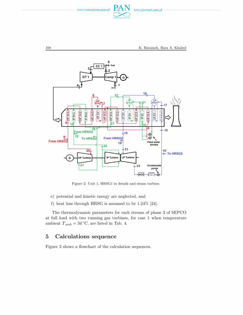
All the readings of temperature, pressure, and flow are acquired from thepower plant control unit. The enthalpy and entropy are calculated using theEngineering Equation Solver (EES) software. Details of Unit 1, HRSG1,and steam turbine are shown in Fig. 2. The analysis is performed for thewhole year to study the seasonal effect. Five cases of operating conditionsare considered. In order to simplify the calculations, several assumptionsare made and can be summarized as follows:
a) steady state flow in each stream in the combined cycle is assumed,
b) air and combustion gases are considered ideal gases,
c) heat losses to the environment are neglected,
d) mechanical efficiencies are assumed to be 100%,
108 K. Bataineh, Bara A. Khaleel
Figure 2: Unit 1, HRSG1 in details and steam turbine.
e) potential and kinetic energy are neglected, and
f) heat loss through HRSG is assumed to be 1.24% [24].
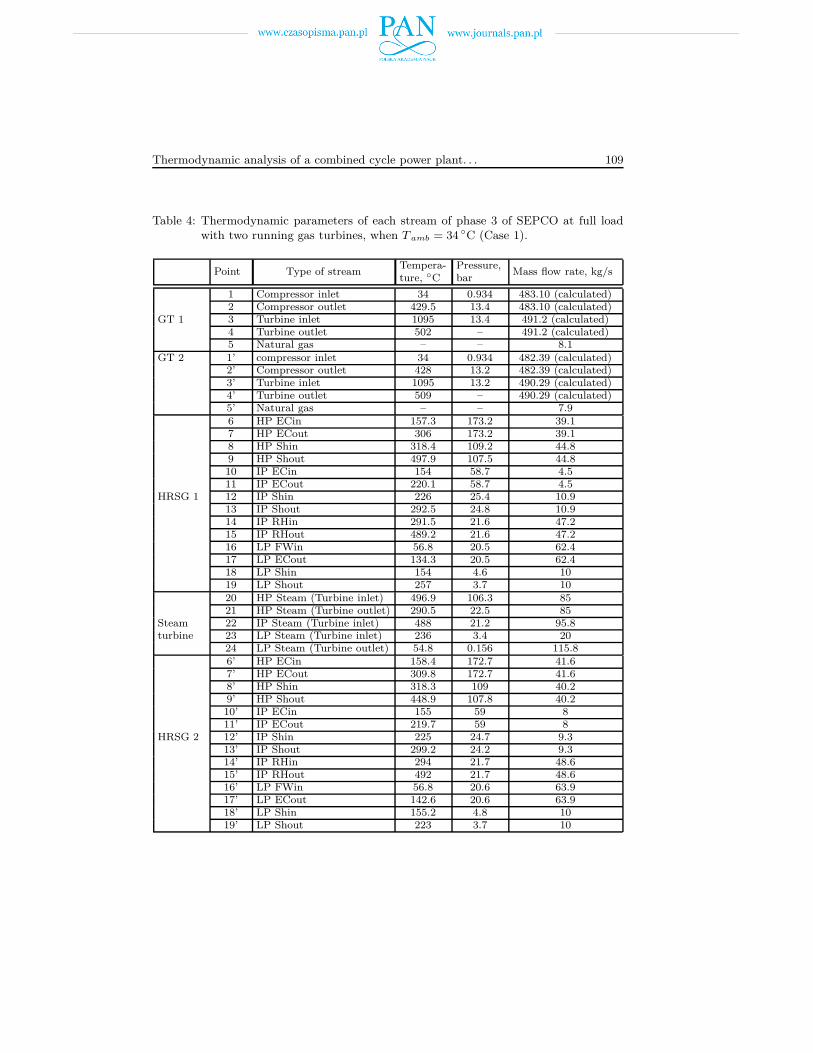
The thermodynamic parameters for each stream of phase 3 of SEPCOat full load with two running gas turbines, for case 1 when temperatureambient T amb = 34 ◦C, are listed in Tab. 4.
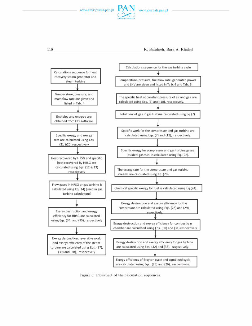
5 Calculations sequence
Figure 3 shows a flowchart of the calculation sequences.
Thermodynamic analysis of a combined cycle power plant. . . 109
Table 4: Thermodynamic parameters of each stream of phase 3 of SEPCO at full loadwith two running gas turbines, when T amb = 34 ◦C (Case 1).
Point Type of streamTempera-ture, ◦C
Pressure,bar
Mass flow rate, kg/s
GT 1
1 Compressor inlet 34 0.934 483.10 (calculated)2 Compressor outlet 429.5 13.4 483.10 (calculated)3 Turbine inlet 1095 13.4 491.2 (calculated)4 Turbine outlet 502 – 491.2 (calculated)5 Natural gas – – 8.1
GT 2 1’ compressor inlet 34 0.934 482.39 (calculated)2’ Compressor outlet 428 13.2 482.39 (calculated)3’ Turbine inlet 1095 13.2 490.29 (calculated)4’ Turbine outlet 509 – 490.29 (calculated)5’ Natural gas – – 7.9
HRSG 1
6 HP ECin 157.3 173.2 39.17 HP ECout 306 173.2 39.18 HP Shin 318.4 109.2 44.89 HP Shout 497.9 107.5 44.810 IP ECin 154 58.7 4.511 IP ECout 220.1 58.7 4.512 IP Shin 226 25.4 10.913 IP Shout 292.5 24.8 10.914 IP RHin 291.5 21.6 47.215 IP RHout 489.2 21.6 47.216 LP FWin 56.8 20.5 62.417 LP ECout 134.3 20.5 62.418 LP Shin 154 4.6 1019 LP Shout 257 3.7 10
Steamturbine
20 HP Steam (Turbine inlet) 496.9 106.3 8521 HP Steam (Turbine outlet) 290.5 22.5 8522 IP Steam (Turbine inlet) 488 21.2 95.823 LP Steam (Turbine inlet) 236 3.4 2024 LP Steam (Turbine outlet) 54.8 0.156 115.8
HRSG 2
6’ HP ECin 158.4 172.7 41.67’ HP ECout 309.8 172.7 41.68’ HP Shin 318.3 109 40.29’ HP Shout 448.9 107.8 40.210’ IP ECin 155 59 811’ IP ECout 219.7 59 812’ IP Shin 225 24.7 9.313’ IP Shout 299.2 24.2 9.314’ IP RHin 294 21.7 48.615’ IP RHout 492 21.7 48.616’ LP FWin 56.8 20.6 63.917’ LP ECout 142.6 20.6 63.918’ LP Shin 155.2 4.8 1019’ LP Shout 223 3.7 10
110 K. Bataineh, Bara A. Khaleel
Flow gases in HRSG or gas turbine is
calculated using Eq.(14) (used in gas
turbine calcula"ons)
Exergy destruc"on and exergy
efficiency for HRSG are calculated
using Eqs. (34) and (35), respec"vely
Exergy destruc"on, reversible work
and exergy efficiency of the steam
turbine are calculated using Eqs. (37),
(39) and (38), respec"vely
Calcula"ons sequence for heat
recovery steam generator and
steam turbine
Temperature, pressure, and
mass flow rate are given and
listed in Tab. 4
Enthalpy and entropy are
obtained from EES so%ware
Specific exergy and exergy
rate are calculated using Eqs.
(21 &20) respec"vely
Heat recovered by HRSG and specific
heat recovered by HRSG are
calculated using Eqs. (12 & 13)
respec"vely
Specific work for the compressor and gas turbine are
calculated using Eqs. (7) and (12), respec"vely.
Specific exergy for compressor and gas turbine gases
(as ideal gases is) is calculated using Eq. (22).
The exergy rate for the compressor and gas turbine
streams are calculated using Eq. (20).
Calcula"ons sequence for the gas turbine cycle
Temperature, pressure, fuel flow rate, generated power
and LHV are given and listed in Ta b. 4 and Tab. 5.
The specific heat at constant pressure of air and gas are
calculated using Eqs. (6) and (10), respec"vely.
Total flow of gas in gas turbine calculated using Eq.(7).
Chemical specific exergy for fuel is calculated using Eq.(24).
Exergy efficiency of Brayton cycle and combined cycle
are calculated using Eqs. (25) and (26), respec"vely.
Exergy destruc"on and exergy efficiency for the
compressor are calculated using Eqs. (28) and (29) ,
respec"vely.
Exergy destruc"on and exergy efficiency for combus"o n
chamber are calculated using Eqs. (30) and (31) respec"vely
Exergy destruc"on and exergy efficiency for gas turbine
are calculated using Eqs. (32) and (33), respectively.
Figure 3: Flowchart of the calculation sequences.
Thermodynamic analysis of a combined cycle power plant. . . 111
6 Results and discussions
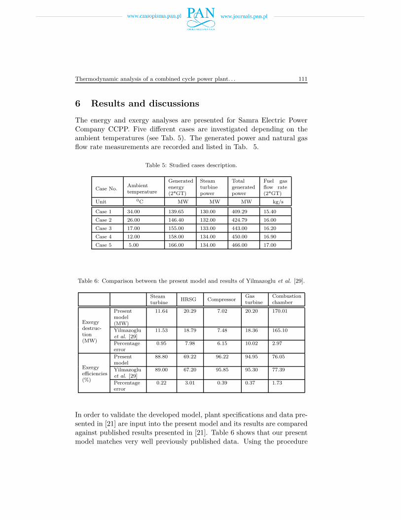
The energy and exergy analyses are presented for Samra Electric PowerCompany CCPP. Five different cases are investigated depending on theambient temperatures (see Tab. 5). The generated power and natural gasflow rate measurements are recorded and listed in Tab. 5.
Table 5: Studied cases description.
Case No.Ambienttemperature
Generatedenergy(2*GT)
Steamturbinepower
Totalgeneratedpower
Fuel gasflow rate(2*GT)
Unit 0C MW MW MW kg/s
Case 1 34.00 139.65 130.00 409.29 15.40
Case 2 26.00 146.40 132.00 424.79 16.00
Case 3 17.00 155.00 133.00 443.00 16.20
Case 4 12.00 158.00 134.00 450.00 16.90
Case 5 5.00 166.00 134.00 466.00 17.00
Table 6: Comparison between the present model and results of Yilmazoglu et al. [29].
Steamturbine
HRSG CompressorGasturbine
Combustionchamber
Exergydestruc-tion(MW)
Presentmodel(MW)
11.64 20.29 7.02 20.20 170.01
Yilmazogluet al. [29]
11.53 18.79 7.48 18.36 165.10
Percentageerror
0.95 7.98 6.15 10.02 2.97
Exergyefficiencies(%)
Presentmodel
88.80 69.22 96.22 94.95 76.05
Yilmazogluet al. [29]
89.00 67.20 95.85 95.30 77.39
Percentageerror
0.22 3.01 0.39 0.37 1.73
In order to validate the developed model, plant specifications and data pre-sented in [21] are input into the present model and its results are comparedagainst published results presented in [21]. Table 6 shows that our presentmodel matches very well previously published data. Using the procedure
112 K. Bataineh, Bara A. Khaleel
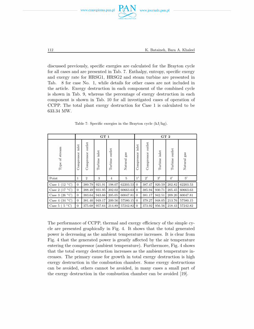
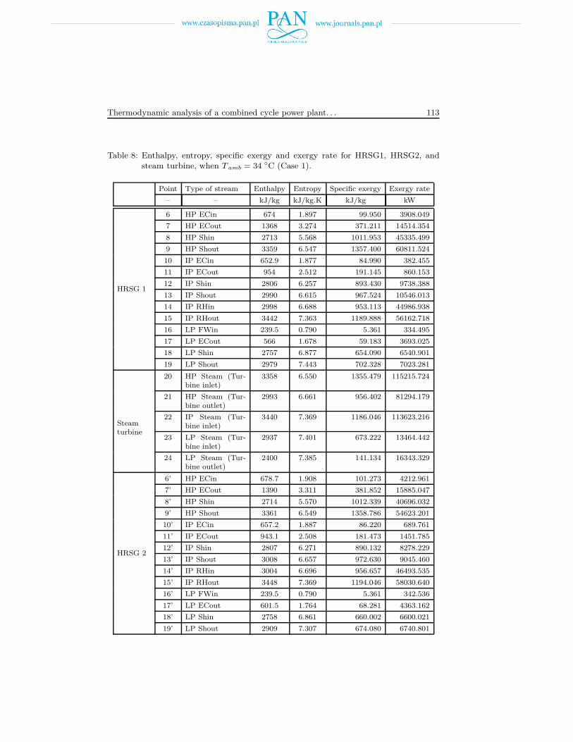
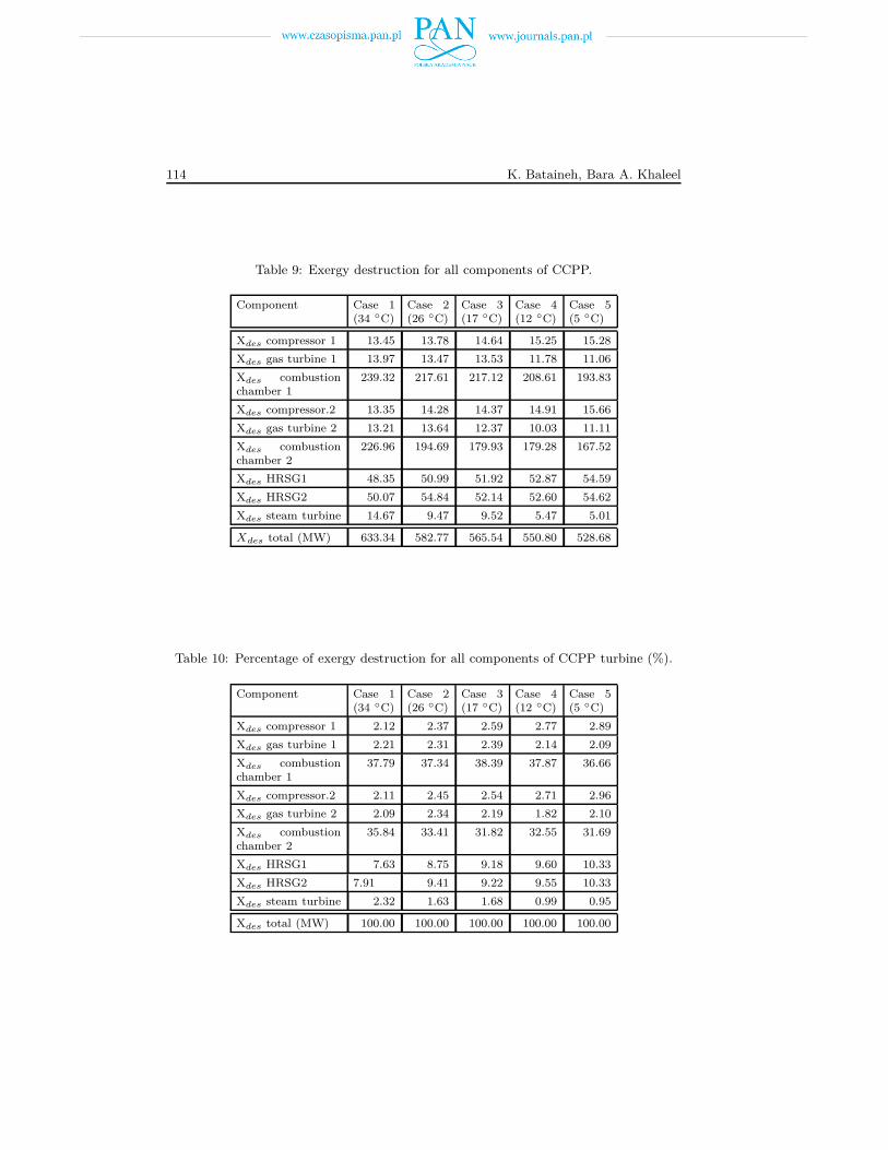
discussed previously, specific exergies are calculated for the Brayton cyclefor all cases and are presented in Tab. 7. Enthalpy, entropy, specific exergyand exergy rate for HRSG1, HRSG2 and steam turbine are presented inTab. 8 for case No. 1, while details for other cases are not included inthe article. Exergy destruction in each component of the combined cycleis shown in Tab. 9, whereas the percentage of exergy destruction in eachcomponent is shown in Tab. 10 for all investigated cases of operation ofCCPP. The total plant exergy destruction for Case 1 is calculated to be633.34 MW.
Table 7: Specific exergies in the Brayton cycle (kJ/kg).
GT 1 GT 2
Typ
eof
stre
am
Com
pre
ssor
inle
t
Com
pre
ssor
ou
tlet
Tu
rbin
ein
let
Tu
rbin
eou
tlet
Natu
ral
gas
Com
pre
ssor
inle
t
Com
pre
ssor
ou
tlet
Tu
rbin
ein
let
Tu
rbin
eou
tlet
Natu
ral
gas
Point 1 2 3 4 5 1′ 2′ 3′ 4′ 5′
Case 1 (12 ◦C) 0 389.79 921.91 198.07 62203.53 0 387.47 920.59 202.82 62203.53
Case 2 (17 ◦C) 0 388.49 931.95 202.02 60663.63 0 385.94 930.71 205.45 60663.63
Case 3 (26 ◦C) 0 383.64 943.66 205.05 60047.81 0 381.17 942.51 209.20 60047.81
Case 4 (34 ◦C) 0 381.40 949.17 209.56 57580.15 0 379.27 948.05 213.76 57580.15
Case 5 ( 5 ◦C) 0 375.68 957.64 214.89 57242.82 0 373.92 956.56 218.43 57242.82
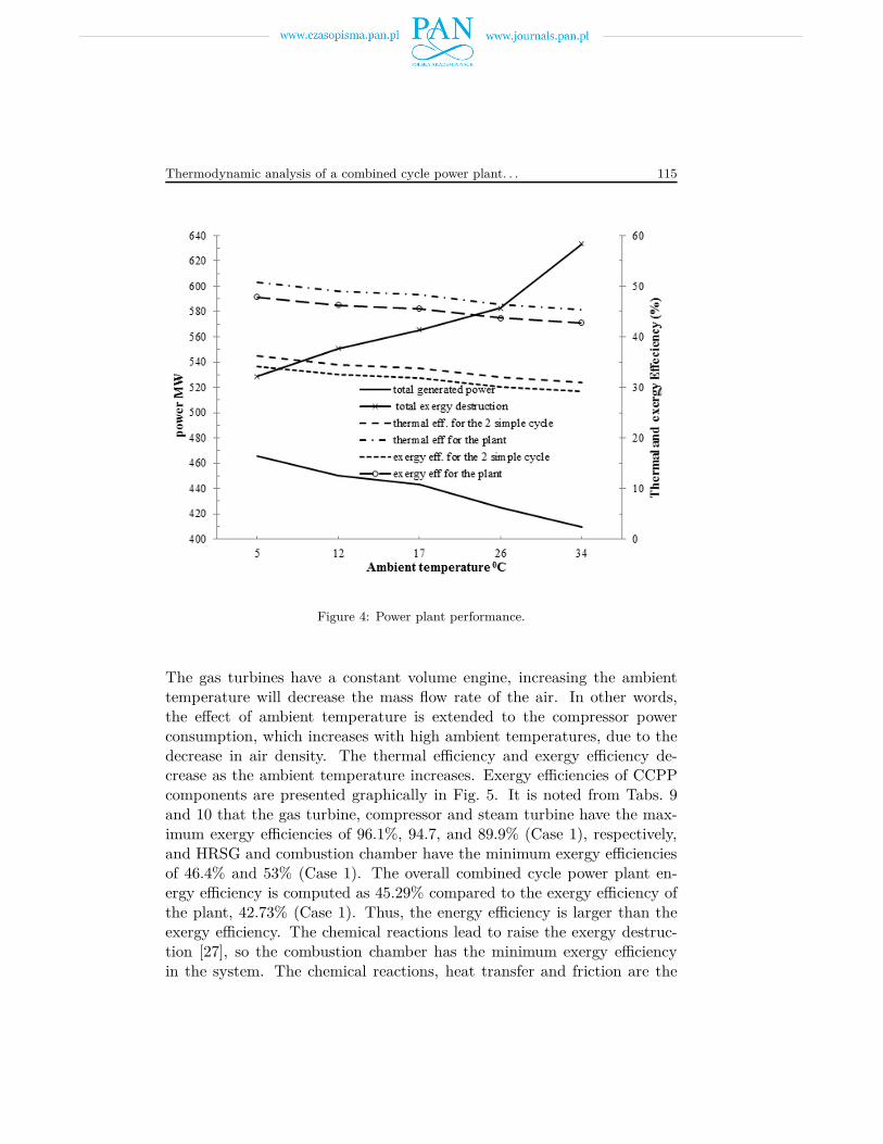
The performance of CCPP, thermal and exergy efficiency of the simple cy-cle are presented graphically in Fig. 4. It shows that the total generatedpower is decreasing as the ambient temperature increases. It is clear fromFig. 4 that the generated power is greatly affected by the air temperatureentering the compressor (ambient temperature). Furthermore, Fig. 4 showsthat the total exergy destruction increases as the ambient temperature in-creases. The primary cause for growth in total exergy destruction is highexergy destruction in the combustion chamber. Some exergy destructionscan be avoided, others cannot be avoided, in many cases a small part ofthe exergy destruction in the combustion chamber can be avoided [19].
Thermodynamic analysis of a combined cycle power plant. . . 113
Table 8: Enthalpy, entropy, specific exergy and exergy rate for HRSG1, HRSG2, andsteam turbine, when T amb = 34 ◦C (Case 1).
Point Type of stream Enthalpy Entropy Specific exergy Exergy rate
– – kJ/kg kJ/kg.K kJ/kg kW
HRSG 1
6 HP ECin 674 1.897 99.950 3908.049
7 HP ECout 1368 3.274 371.211 14514.354
8 HP Shin 2713 5.568 1011.953 45335.499
9 HP Shout 3359 6.547 1357.400 60811.524
10 IP ECin 652.9 1.877 84.990 382.455
11 IP ECout 954 2.512 191.145 860.153
12 IP Shin 2806 6.257 893.430 9738.388
13 IP Shout 2990 6.615 967.524 10546.013
14 IP RHin 2998 6.688 953.113 44986.938
15 IP RHout 3442 7.363 1189.888 56162.718
16 LP FWin 239.5 0.790 5.361 334.495
17 LP ECout 566 1.678 59.183 3693.025
18 LP Shin 2757 6.877 654.090 6540.901
19 LP Shout 2979 7.443 702.328 7023.281
Steamturbine
20 HP Steam (Tur-bine inlet)
3358 6.550 1355.479 115215.724
21 HP Steam (Tur-bine outlet)
2993 6.661 956.402 81294.179
22 IP Steam (Tur-bine inlet)
3440 7.369 1186.046 113623.216
23 LP Steam (Tur-bine inlet)
2937 7.401 673.222 13464.442
24 LP Steam (Tur-bine outlet)
2400 7.385 141.134 16343.329
HRSG 2
6’ HP ECin 678.7 1.908 101.273 4212.961
7’ HP ECout 1390 3.311 381.852 15885.047
8’ HP Shin 2714 5.570 1012.339 40696.032
9’ HP Shout 3361 6.549 1358.786 54623.201
10’ IP ECin 657.2 1.887 86.220 689.761
11’ IP ECout 943.1 2.508 181.473 1451.785
12’ IP Shin 2807 6.271 890.132 8278.229
13’ IP Shout 3008 6.657 972.630 9045.460
14’ IP RHin 3004 6.696 956.657 46493.535
15’ IP RHout 3448 7.369 1194.046 58030.640
16’ LP FWin 239.5 0.790 5.361 342.536
17’ LP ECout 601.5 1.764 68.281 4363.162
18’ LP Shin 2758 6.861 660.002 6600.021
19’ LP Shout 2909 7.307 674.080 6740.801
114 K. Bataineh, Bara A. Khaleel
Table 9: Exergy destruction for all components of CCPP.
Component Case 1(34 ◦C)
Case 2(26 ◦C)
Case 3(17 ◦C)
Case 4(12 ◦C)
Case 5(5 ◦C)
Xdes compressor 1 13.45 13.78 14.64 15.25 15.28
Xdes gas turbine 1 13.97 13.47 13.53 11.78 11.06
Xdes combustionchamber 1
239.32 217.61 217.12 208.61 193.83
Xdes compressor.2 13.35 14.28 14.37 14.91 15.66
Xdes gas turbine 2 13.21 13.64 12.37 10.03 11.11
Xdes combustionchamber 2
226.96 194.69 179.93 179.28 167.52
Xdes HRSG1 48.35 50.99 51.92 52.87 54.59
Xdes HRSG2 50.07 54.84 52.14 52.60 54.62
Xdes steam turbine 14.67 9.47 9.52 5.47 5.01
Xdes total (MW) 633.34 582.77 565.54 550.80 528.68
Table 10: Percentage of exergy destruction for all components of CCPP turbine (%).
Component Case 1(34 ◦C)
Case 2(26 ◦C)
Case 3(17 ◦C)
Case 4(12 ◦C)
Case 5(5 ◦C)
Xdes compressor 1 2.12 2.37 2.59 2.77 2.89
Xdes gas turbine 1 2.21 2.31 2.39 2.14 2.09
Xdes combustionchamber 1
37.79 37.34 38.39 37.87 36.66
Xdes compressor.2 2.11 2.45 2.54 2.71 2.96
Xdes gas turbine 2 2.09 2.34 2.19 1.82 2.10
Xdes combustionchamber 2
35.84 33.41 31.82 32.55 31.69
Xdes HRSG1 7.63 8.75 9.18 9.60 10.33
Xdes HRSG2 7.91 9.41 9.22 9.55 10.33
Xdes steam turbine 2.32 1.63 1.68 0.99 0.95
Xdes total (MW) 100.00 100.00 100.00 100.00 100.00
Thermodynamic analysis of a combined cycle power plant. . . 115
Figure 4: Power plant performance.
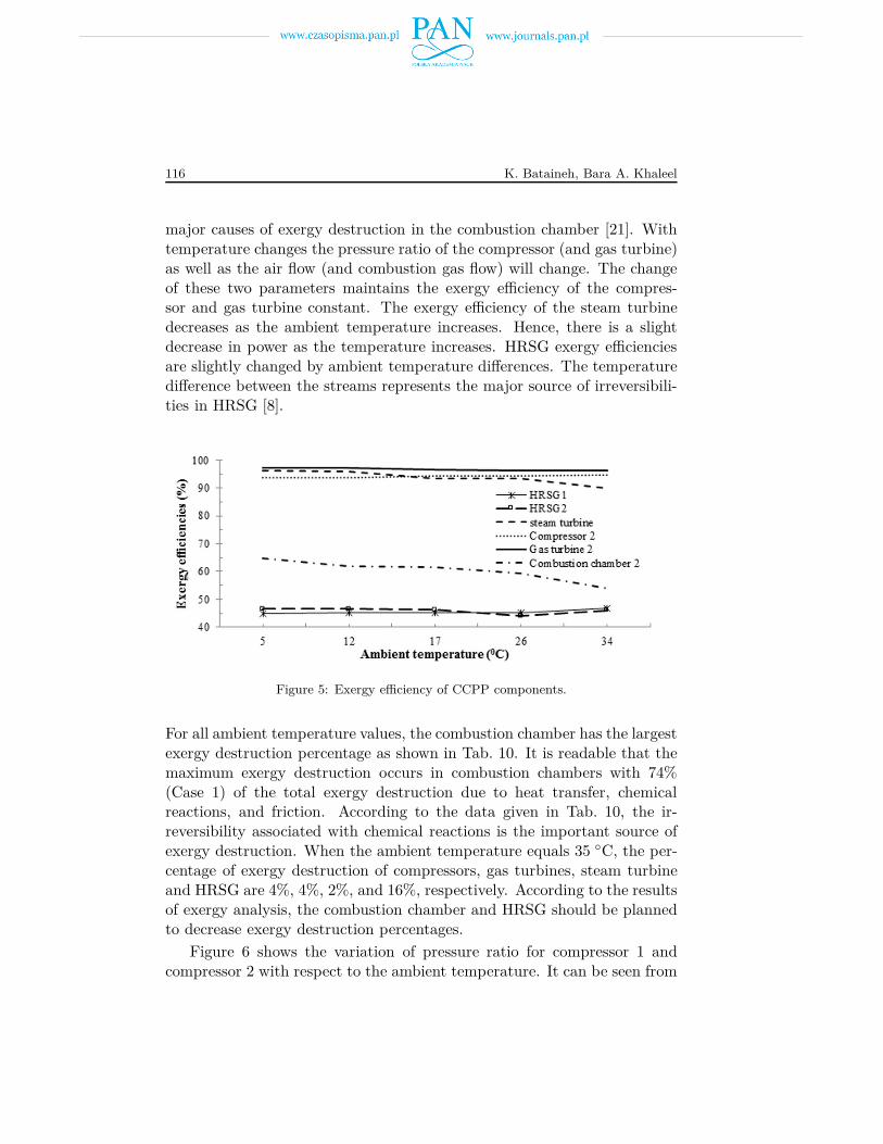
The gas turbines have a constant volume engine, increasing the ambienttemperature will decrease the mass flow rate of the air. In other words,the effect of ambient temperature is extended to the compressor powerconsumption, which increases with high ambient temperatures, due to thedecrease in air density. The thermal efficiency and exergy efficiency de-crease as the ambient temperature increases. Exergy efficiencies of CCPPcomponents are presented graphically in Fig. 5. It is noted from Tabs. 9and 10 that the gas turbine, compressor and steam turbine have the max-imum exergy efficiencies of 96.1%, 94.7, and 89.9% (Case 1), respectively,and HRSG and combustion chamber have the minimum exergy efficienciesof 46.4% and 53% (Case 1). The overall combined cycle power plant en-ergy efficiency is computed as 45.29% compared to the exergy efficiency ofthe plant, 42.73% (Case 1). Thus, the energy efficiency is larger than theexergy efficiency. The chemical reactions lead to raise the exergy destruc-tion [27], so the combustion chamber has the minimum exergy efficiencyin the system. The chemical reactions, heat transfer and friction are the
116 K. Bataineh, Bara A. Khaleel
major causes of exergy destruction in the combustion chamber [21]. Withtemperature changes the pressure ratio of the compressor (and gas turbine)as well as the air flow (and combustion gas flow) will change. The changeof these two parameters maintains the exergy efficiency of the compres-sor and gas turbine constant. The exergy efficiency of the steam turbinedecreases as the ambient temperature increases. Hence, there is a slightdecrease in power as the temperature increases. HRSG exergy efficienciesare slightly changed by ambient temperature differences. The temperaturedifference between the streams represents the major source of irreversibili-ties in HRSG [8].
Figure 5: Exergy efficiency of CCPP components.
For all ambient temperature values, the combustion chamber has the largestexergy destruction percentage as shown in Tab. 10. It is readable that themaximum exergy destruction occurs in combustion chambers with 74%(Case 1) of the total exergy destruction due to heat transfer, chemicalreactions, and friction. According to the data given in Tab. 10, the ir-reversibility associated with chemical reactions is the important source ofexergy destruction. When the ambient temperature equals 35 ◦C, the per-centage of exergy destruction of compressors, gas turbines, steam turbineand HRSG are 4%, 4%, 2%, and 16%, respectively. According to the resultsof exergy analysis, the combustion chamber and HRSG should be plannedto decrease exergy destruction percentages.
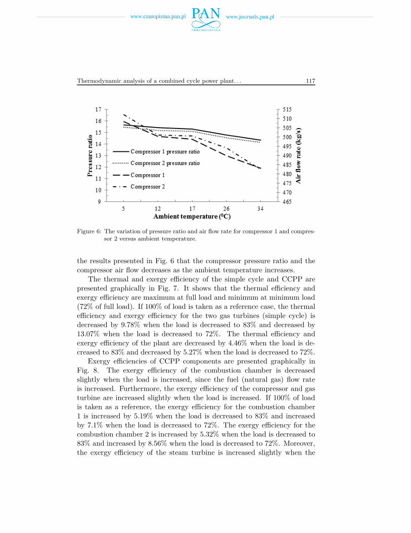
Figure 6 shows the variation of pressure ratio for compressor 1 andcompressor 2 with respect to the ambient temperature. It can be seen from
Thermodynamic analysis of a combined cycle power plant. . . 117
Figure 6: The variation of pressure ratio and air flow rate for compressor 1 and compres-sor 2 versus ambient temperature.
the results presented in Fig. 6 that the compressor pressure ratio and thecompressor air flow decreases as the ambient temperature increases.
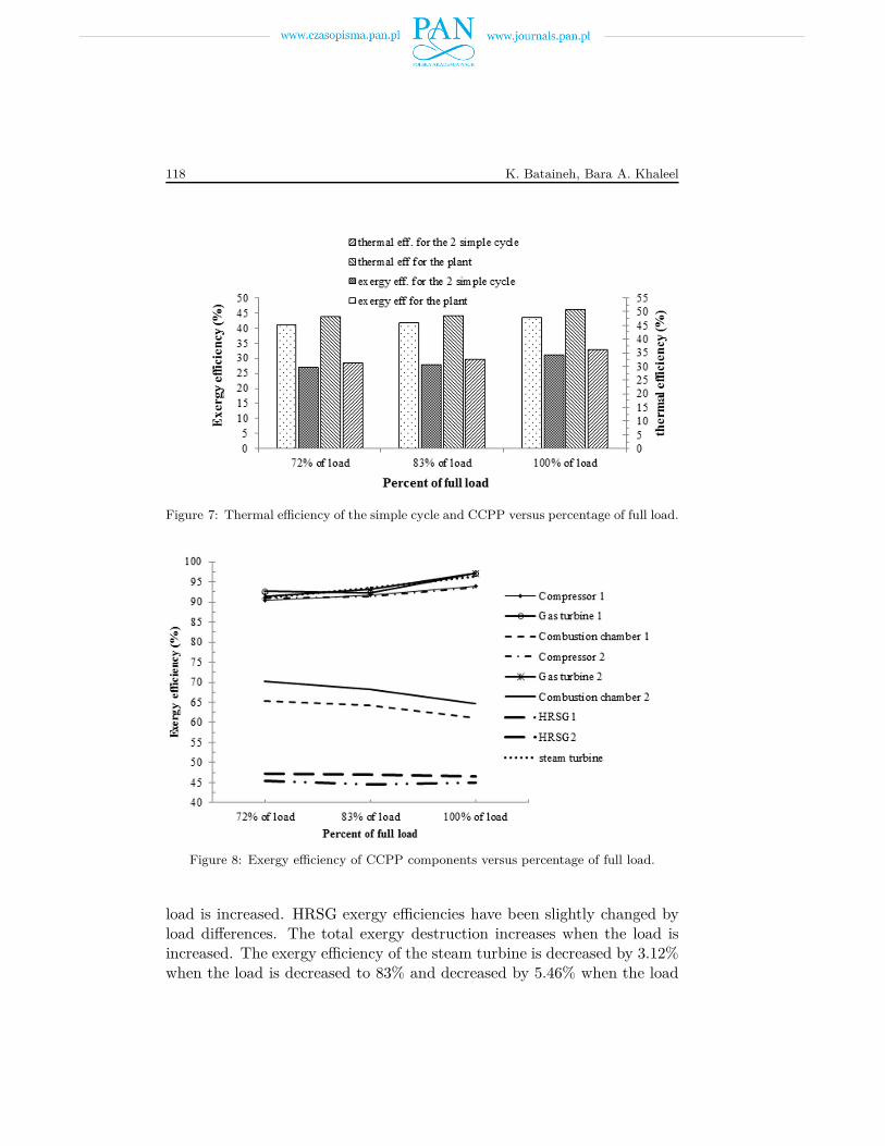
The thermal and exergy efficiency of the simple cycle and CCPP arepresented graphically in Fig. 7. It shows that the thermal efficiency andexergy efficiency are maximum at full load and minimum at minimum load(72% of full load). If 100% of load is taken as a reference case, the thermalefficiency and exergy efficiency for the two gas turbines (simple cycle) isdecreased by 9.78% when the load is decreased to 83% and decreased by13.07% when the load is decreased to 72%. The thermal efficiency andexergy efficiency of the plant are decreased by 4.46% when the load is de-creased to 83% and decreased by 5.27% when the load is decreased to 72%.
Exergy efficiencies of CCPP components are presented graphically inFig. 8. The exergy efficiency of the combustion chamber is decreasedslightly when the load is increased, since the fuel (natural gas) flow rateis increased. Furthermore, the exergy efficiency of the compressor and gasturbine are increased slightly when the load is increased. If 100% of loadis taken as a reference, the exergy efficiency for the combustion chamber1 is increased by 5.19% when the load is decreased to 83% and increasedby 7.1% when the load is decreased to 72%. The exergy efficiency for thecombustion chamber 2 is increased by 5.32% when the load is decreased to83% and increased by 8.56% when the load is decreased to 72%. Moreover,the exergy efficiency of the steam turbine is increased slightly when the
118 K. Bataineh, Bara A. Khaleel
Figure 7: Thermal efficiency of the simple cycle and CCPP versus percentage of full load.
Figure 8: Exergy efficiency of CCPP components versus percentage of full load.
load is increased. HRSG exergy efficiencies have been slightly changed byload differences. The total exergy destruction increases when the load isincreased. The exergy efficiency of the steam turbine is decreased by 3.12%when the load is decreased to 83% and decreased by 5.46% when the load
Thermodynamic analysis of a combined cycle power plant. . . 119
is decreased to 72%. The total exergy destruction is decreased by 7.65%when the load is decreased to 83% and decreased by 18.09% when the loadis decreased to 72%.
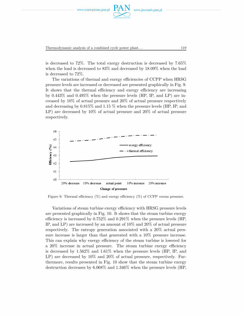
The variations of thermal and exergy efficiencies of CCPP when HRSGpressure levels are increased or decreased are presented graphically in Fig. 9.It shows that the thermal efficiency and exergy efficiency are increasingby 0.443% and 0.495% when the pressure levels (HP, IP, and LP) are in-creased by 10% of actual pressure and 20% of actual pressure respectivelyand decreasing by 0.815% and 1.15 % when the pressure levels (HP, IP, andLP) are decreased by 10% of actual pressure and 20% of actual pressurerespectively.
Figure 9: Thermal efficiency (%) and exergy efficiency (%) of CCPP versus pressure.
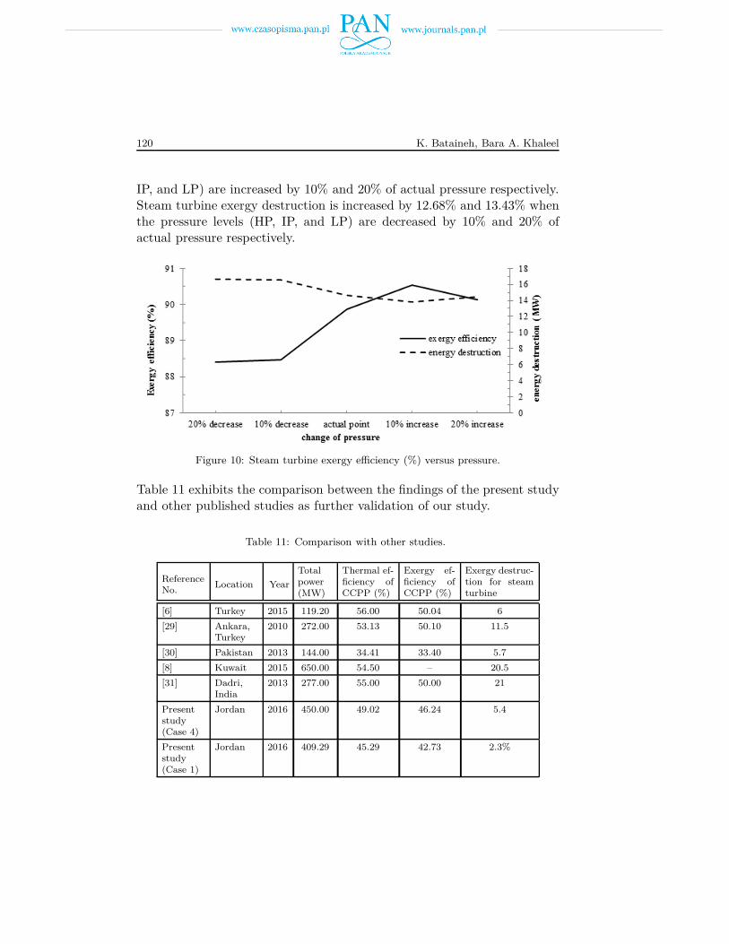
Variations of steam turbine exergy efficiency with HRSG pressure levelsare presented graphically in Fig. 10. It shows that the steam turbine exergyefficiency is increased by 0.752% and 0.291% when the pressure levels (HP,IP, and LP) are increased by an amount of 10% and 20% of actual pressurerespectively. The entropy generation associated with a 20% actual pres-sure increase is larger than that generated with a 10% pressure increase.This can explain why exergy efficiency of the steam turbine is lowered fora 20% increase in actual pressure. The steam turbine exergy efficiencyis decreased by 1.562% and 1.61% when the pressure levels (HP, IP, andLP) are decreased by 10% and 20% of actual pressure, respectively. Fur-thermore, results presented in Fig. 10 show that the steam turbine exergydestruction decreases by 6.068% and 1.346% when the pressure levels (HP,
120 K. Bataineh, Bara A. Khaleel
IP, and LP) are increased by 10% and 20% of actual pressure respectively.Steam turbine exergy destruction is increased by 12.68% and 13.43% whenthe pressure levels (HP, IP, and LP) are decreased by 10% and 20% ofactual pressure respectively.
Figure 10: Steam turbine exergy efficiency (%) versus pressure.
Table 11 exhibits the comparison between the findings of the present studyand other published studies as further validation of our study.
Table 11: Comparison with other studies.
ReferenceNo.
Location Year
Totalpower(MW)
Thermal ef-ficiency ofCCPP (%)
Exergy ef-ficiency ofCCPP (%)
Exergy destruc-tion for steamturbine
[6] Turkey 2015 119.20 56.00 50.04 6
[29] Ankara,Turkey
2010 272.00 53.13 50.10 11.5
[30] Pakistan 2013 144.00 34.41 33.40 5.7
[8] Kuwait 2015 650.00 54.50 – 20.5
[31] Dadri,India
2013 277.00 55.00 50.00 21
Presentstudy(Case 4)
Jordan 2016 450.00 49.02 46.24 5.4
Presentstudy(Case 1)
Jordan 2016 409.29 45.29 42.73 2.3%
Thermodynamic analysis of a combined cycle power plant. . . 121
7 Conclusion
The irreversibility of each part of the combined cycle power plant locatedin Jordan using the exergy and energy analyses are evaluated. The effect ofambient temperature, gas turbine pressure ratio, gas turbine inlet temper-ature, and load conditions on the combined cycle efficiency, power outputsand exergy destruction are investigated. The results show that
• Energy and exergy efficiencies of the combined cycle power plant arefound as 45.29% and 42.73% (Case 1), respectively.
• The gas turbine, compressor, and steam turbine have the maximumexergy efficiencies of 96.1%, 94.7%, and 89.9% (Case 1), respectively.
• HRSG and combustion chamber have the minimum exergy efficienciesof 46.4% and 53% (Case 1).
• The maximum exergy destruction occurs in combustion chamberswith 74% (Case 1) of the total exergy destruction due to heat transfer,chemical reactions, and friction.
• The irreversibility associated with chemical reactions is the importantsource of exergy destruction.
• The energy and exergy efficiencies of the combined cycle power plantare decreasing as the ambient temperature increases.
• The combined cycle power plant has the maximum energy and exergyefficiencies at full load.
• The thermal efficiency and exergy efficiency are increased when pres-sure levels (HP, IP, and LP) are increased.
• The steam turbine exergy efficiency is increased with an increase ofpressure.
Received 9 May 2018, received in revised form 17 September 2018
References
[1] Ziebik A.: Thermodynamical motivation of the Polish energy policy. Arch. Ther-modyn. 33(2011), 3–21, DOI:10.2478/v10173-012-0025-9.
122 K. Bataineh, Bara A. Khaleel
[2] Budnik M., Stanek W.: Exergetic cost of steam power plant operation. Arch.Thermodyn. 32(2011), 2, 39–54, DOI: 10.2478/v10173-011-0008-2.
[3] Rosen M.A.: Clarifying thermodynamic efficiencies and losses via exergy. Exergy2(2002), 3–5.
[4] Kakaras E.: Inlet air cooling methods for gas turbine based power plant. J. Eng.Gas Turb. Power ASME 128(2006), 2, 312–317.
[5] Ibrahim T.K., Mohammed M.K., Awad O.I. , Abdallad A.N., Basrawic F.,Mohammed M.N., Najafif G., Mamat R.: A comprehensive review on the exergyanalysis of combined cycle power plants. Renew. Sust. Energ. Rev. 90(2018), 835–850.
[6] Ersayin E., Ozgener L.: Performance analysis of combined cycle power plants:A case study. Renew. Sust. Energ. Rev. 43(2015), 832–842.
[7] Petrakopoulou F., Tsatsaronis G., Morosuk T., Carassai A.: Conventionaland advanced exergetic analyses applied to a combined cycle power plant. Energy41(2012), 146–52.
[8] Almutairi A., Pilidis P., Al-Mutawa N.: Energetic and exergetic analysis ofcombined cycle power plant: Part-1, Operation and performance. Energies 8(2015),12, 14118–14135.
[9] Aljundi I.: Energy and exergy analysis of a steam power plant in Jordan. Appl.Therm. Eng. 29(2009), 324–328.
[10] Srinivas T., Gupta A., Reddy B.: Thermodynamic modeling and optimizationof multipressure heat recovery steam generator in combined power cycle. J. Sci. Ind.Res. 67(2008), 827–834.
[11] Li Q, Lin Y.: Exergy analysis of the LFC process. Energ. Convers. Manage.108(2016), 348–354.
[12] Maheshwari M., Singh O.: Exergy analysis of intercooled reheat combined cyclewith ammonia water mixture based bottoming cycle. Appl. Therm. Eng. 121(2017),820–827.
[13] Abuelnuor A.A.A., Saqr K.M., Mohieldein S.A.A., Dafallah K.A., Abdul-lah M.M., Nogoud Y.A.M.: Exergy analysis of Garri “2” 180 MW combined cyclepower plant. Renew. Sust. Energ. Rev. 79(2017), 960–969.
[14] Terzi R, Tükenmez I., Kurt E.: Energy and exergy analyses of a VVER typenuclear power plant. Int. J. Hydrogen Energy 41(2016), 12465–12476.
[15] Kumar R.: A critical review on energy, exergy, exergoeconomic and economic (4-E)analysis of thermal power plants. Eng. Sci. Technol. 20(2017), 283–292.
[16] Dhar Garg P., Dehiya S., Barasiya A., Rahangdale A., Shankar KumawatV.: Exergy and efficiency analysis of combined cycle power plant. Int. J. Sci. Eng.Res. 4(2013), 2229–5518.
[17] Woudstra N., Woudstra T., Pirone A., Stelt T.: Thermodynamic evaluationof combined cycle plants. Energy Convers. Manage 51(2010), 1099–1110.
[18] Bagdanavicius A., Jenkins N., Hammond G.: Assessment of community energysupply systems using energy, exergy and exergoeconomic analysis. Energy 45(2012),247–255.
Thermodynamic analysis of a combined cycle power plant. . . 123
[19] Mohapatra A.K.: Thermodynamic assessment of impact of inlet air cooling tech-niques on gas turbine and combined cycle performance. Energy 68(2014), 191–203.
[20] Boonnasa S., Namprakai P., Muangnapoh T.: Performance improvement ofthe combined cycle power plant by intake air cooling using an absorption chiller.Energy 31(2006), 12, 1700–1710.
[21] Gadhamshetty V., Nirmalakhandan N., Myint M., Ricketts C.: Improvingair-cooled condenser performance in combined cycle power plants. J Eng. Energy132(2006), 2, 81–88.
[22] Nirmalakhandan N., Gadhamshetty V., Mummaneni A.: Improving combinedcycle power plant performance. In: Proc. 6th Int. Conf. Heat Transfer, Fluid Me-chanics and Thermodynamics 2008, 1–6.
[23] Oko C.O.C., Njoku I.H.: Performance analysis of an integrated gas-, steam- andorganic fluid-cycle thermal power plant. Energy 122(2017), 431–443.
[24] SEPCO manuals.
[25] Recebli Kurt H., Gredik E.: Performance analysis of open cycle gas turbines.Int. J. Energy Res. 33(2009), 2, 285–94.
[26] Kotas T.J.: The Exergy Method of Thermal Plant Analysis. Krieger PublishingCompany, Florida 1995.
[27] Bejan A., Tsatsaronis G., Moran M.: Thermal Design and Optimization (1stEdn.). John Wiley and Sons, New York 1995.
[28] Zadpoor A.A., Golshan A.H.: Performance improvement of a gas turbine cycleby using a desiccant based evaporative cooling system. Energy 31(2006), 2652–2664.
[29] Yilmazoglu M.Z., Amirabedin E.: Second law and sensitivity analysis of a com-bined cycle power plant in turkey. J. Thermal Sci. Technol. 2(2011), 41–50.
[30] Memon A.G., Harihan K., Shah S.F., Memon R.A., Uqality M.A.: Ex-ergy analysis of 144 MW combined cycle power plant Kotri Pakistan. SindhUni. Res. J. (Sci. Ser.), 45(2013), 107–112.
[31] Tiwari1 A.K., Hasan M.M., Islam M.: Effect of ambient temperature on theperformance of a combined cycle power plant. Trans. Canadian Soc. Mech. Eng.37(2013), 4, 1177–1188.
Related Documents