Thermo Scientific Sorvall X Pro / ST Plus Series Centrifuges Instructions for Use 50158527-d • 08 / 2019

Welcome message from author
This document is posted to help you gain knowledge. Please leave a comment to let me know what you think about it! Share it to your friends and learn new things together.
Transcript

Thermo ScientificSorvall X Pro / ST Plus Series Centrifuges
Instructions for Use50158527-d • 08 / 2019
ii
Table of Contents
Preface
About this Manual x
Where Do I Find Information about my Centrifuge? x
Intended Use x
Signal Words and Symbols xi
Symbols used on Unit and Accessories xii
Symbols used in the Instructions for Use xii
Safety Instructions xii
1. Transport and Set Up
1. 1. Unpacking 1-1
1. 2. Location 1-1
1. 3. Transporting 1-2
1. 4. Product Overview 1-3
1. 5. Connections 1-5
1. 6. Initial Startup 1-5
2. Operation
2. 1. Position of parts 2-1
2. 2. Power on/off the Centrifuge 2-3
2. 3. Open/Close the Centrifuge Lid 2-3
2. 4. How to Install and Remove a Rotor 2-3
2. 5. Load the Rotor 2-6
iii
2. 6. Identify Rotor and Buckets 2-8
2. 7. Set Basic Centrifugation Parameters 2-9
2. 8. Pre-Temper the Centrifugation Chamber 2-10
2. 9. Centrifugation 2-10
2. 10. Aerosol-Tight Applications 2-11
3. Graphical User Interface
3. 1. Overview 3-1
3. 2. Set Basic Centrifugation Parameters 3-6
3. 3. Pre-Temper the Centrifugation Chamber 3-11
3. 4. Centrifugation 3-12
3. 5. Status, Alarms and Alerts 3-14
3. 6. Settings 3-29
3. 7. Display 3-41
3. 8. Logs 3-44
4. LCD Control Panel
4. 1. Overview 4-1
4. 2. Set Basic Centrifugation Parameters 4-2
4. 3. Programs 4-6
4. 4. Centrifugation 4-6
4. 5. Stop an Ongoing Centrifugation Run 4-7
4. 6. System Menu 4-8
iv
5. Maintenance and Care
5. 1. Cleaning Intervals 5-1
5. 2. Basics 5-1
5. 3. Cleaning 5-2
5. 4. Disinfection 5-4
5. 5. Decontamination 5-4
5. 6. Autoclaving 5-5
5. 7. Maintenance 5-5
5. 8. Shipping 5-6
5. 9. Storage 5-6
5. 10. Disposal 5-6
6. Troubleshooting
6. 1. Mechanical Emergency Door Release 6-1
6. 2. Ice Formation 6-1
6. 3. Troubleshooting by Guide 6-2
6. 4. Information for the Customer Service 6-3
A. Technical Specifications
B. Rotor Specifications
C. Chemical Compatibility
v
List of Figures
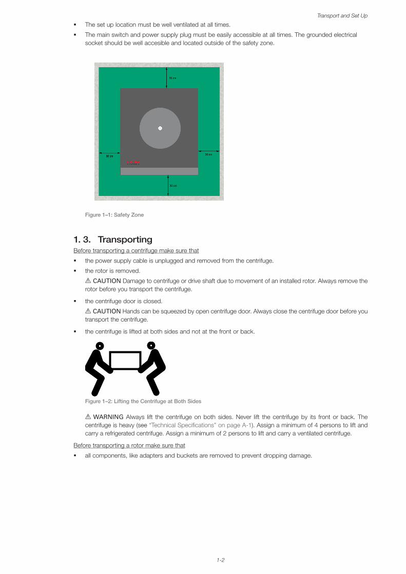
Figure 1–1: Safety Zone � � � � � � � � � � � � � � � � � � � � � � � � � � � � � � � � � � � � � � � � � � � � � � � � � � � � � � � � � � � � � � � � � � � � � � 1-2
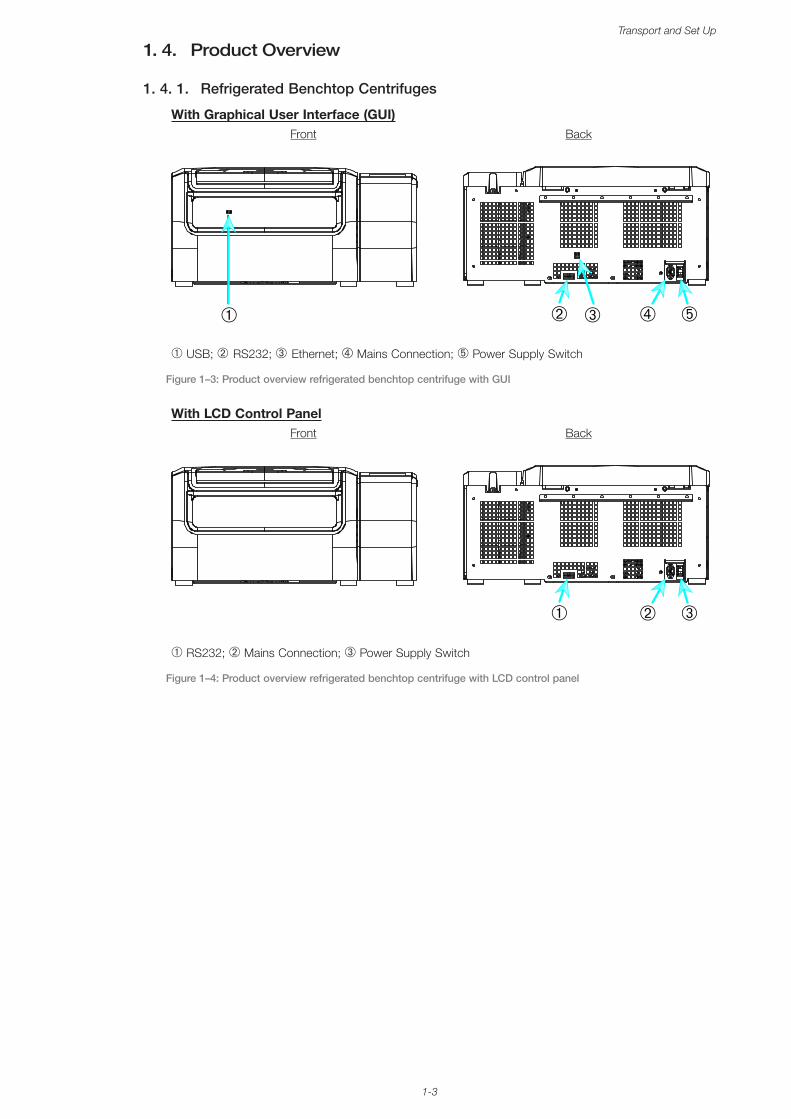
Figure 1–2: Lifting the Centrifuge at Both Sides � � � � � � � � � � � � � � � � � � � � � � � � � � � � � � � � � � � � � � � � � � � � � � � � � � � 1-2
Figure 1–3: Product overview refrigerated benchtop centrifuge with GUI � � � � � � � � � � � � � � � � � � � � � � � � � � � � � � � 1-3
Figure 1–4: Product overview refrigerated benchtop centrifuge with LCD control panel � � � � � � � � � � � � � � � � � � � � 1-3
Figure 1–5: Product overview ventilated benchtop centrifuge with GUI � � � � � � � � � � � � � � � � � � � � � � � � � � � � � � � � 1-4
Figure 1–6: Product overview ventilated benchtop centrifuge with LCD control panel � � � � � � � � � � � � � � � � � � � � � 1-4
Figure 2–1: Position of centrifuge parts shown on a ventilated centrifuge with LCD control panel � � � � � � � � � � � 2-1
Figure 2–2: Position of rotor parts shown on a fixed angle rotor � � � � � � � � � � � � � � � � � � � � � � � � � � � � � � � � � � � � � � 2-1
Figure 2–3: Position of rotor parts shown on a swing out rotor � � � � � � � � � � � � � � � � � � � � � � � � � � � � � � � � � � � � � � � 2-2
Figure 2–4: Position of rotor parts shown on a windshielded swing out rotor � � � � � � � � � � � � � � � � � � � � � � � � � � � � 2-2
Figure 2–5: Rear view of the centrifuge, position of the mains switch � � � � � � � � � � � � � � � � � � � � � � � � � � � � � � � � � � 2-3
Figure 2–6: Put on/off the rotor lid � � � � � � � � � � � � � � � � � � � � � � � � � � � � � � � � � � � � � � � � � � � � � � � � � � � � � � � � � � � � � 2-4
Figure 2–7: Turn the rotor knob � � � � � � � � � � � � � � � � � � � � � � � � � � � � � � � � � � � � � � � � � � � � � � � � � � � � � � � � � � � � � � � � 2-4
Figure 2–8: Pressing the Auto-Lock key � � � � � � � � � � � � � � � � � � � � � � � � � � � � � � � � � � � � � � � � � � � � � � � � � � � � � � � � � 2-5
Figure 2–9: Auto-Lock on the drive shaft � � � � � � � � � � � � � � � � � � � � � � � � � � � � � � � � � � � � � � � � � � � � � � � � � � � � � � � � 2-5
Figure 2–10: Correct loading examples for fixed angle rotors � � � � � � � � � � � � � � � � � � � � � � � � � � � � � � � � � � � � � � � � 2-6
Figure 2–11: Correct loading examples for swing out rotors � � � � � � � � � � � � � � � � � � � � � � � � � � � � � � � � � � � � � � � � � 2-6
Figure 2–12: Incorrect loading examples for fixed angle rotors � � � � � � � � � � � � � � � � � � � � � � � � � � � � � � � � � � � � � � � 2-6
Figure 2–13: Incorrect loading examples for swing out rotors � � � � � � � � � � � � � � � � � � � � � � � � � � � � � � � � � � � � � � � � 2-6
Figure 2–14: Rotor Detection: Choosing a Bucket Type for a TX-750 Rotor � � � � � � � � � � � � � � � � � � � � � � � � � � � � � 2-8
Figure 2–15: Setting the Correct Bucket Code � � � � � � � � � � � � � � � � � � � � � � � � � � � � � � � � � � � � � � � � � � � � � � � � � � � � 2-9
Figure 2–16: Lid of an aerosol-tight rotor with mandrel � � � � � � � � � � � � � � � � � � � � � � � � � � � � � � � � � � � � � � � � � � � � 2-11
Figure 2–17: Bucket with open lid (left) and closed lid (right) � � � � � � � � � � � � � � � � � � � � � � � � � � � � � � � � � � � � � � � � 2-12
Figure 3–1: Screen Areas � � � � � � � � � � � � � � � � � � � � � � � � � � � � � � � � � � � � � � � � � � � � � � � � � � � � � � � � � � � � � � � � � � � � � 3-1
Figure 3–2: Touchscreen Display for Ventilated Centrifuge � � � � � � � � � � � � � � � � � � � � � � � � � � � � � � � � � � � � � � � � � � 3-1
Figure 3–3: Touchscreen Display for Refrigerated Centrifuge � � � � � � � � � � � � � � � � � � � � � � � � � � � � � � � � � � � � � � � � � 3-2
Figure 3–4: Info & Health Status Area � � � � � � � � � � � � � � � � � � � � � � � � � � � � � � � � � � � � � � � � � � � � � � � � � � � � � � � � � � � 3-2
Figure 3–5: Home Screen for Idle Centrifuge � � � � � � � � � � � � � � � � � � � � � � � � � � � � � � � � � � � � � � � � � � � � � � � � � � � � � 3-3
Figure 3–6: Home Screen for Running Centrifuge, Ventilated Models � � � � � � � � � � � � � � � � � � � � � � � � � � � � � � � � � 3-3
Figure 3–7: Home Screen for Running Centrifuge, Refrigerated Models � � � � � � � � � � � � � � � � � � � � � � � � � � � � � � � � 3-3
Figure 3–8: Settings Main Screen � � � � � � � � � � � � � � � � � � � � � � � � � � � � � � � � � � � � � � � � � � � � � � � � � � � � � � � � � � � � � � 3-4
Figure 3–9: Control Panel for Ventilated Centrifuge � � � � � � � � � � � � � � � � � � � � � � � � � � � � � � � � � � � � � � � � � � � � � � � � 3-5
Figure 3–10: Control Panel for Refrigerated Centrifuge � � � � � � � � � � � � � � � � � � � � � � � � � � � � � � � � � � � � � � � � � � � � � 3-5
Figure 3–11: Navigation bar � � � � � � � � � � � � � � � � � � � � � � � � � � � � � � � � � � � � � � � � � � � � � � � � � � � � � � � � � � � � � � � � � � 3-6
Figure 3–12: Speed Box on Home Screen � � � � � � � � � � � � � � � � � � � � � � � � � � � � � � � � � � � � � � � � � � � � � � � � � � � � � � � 3-7
Figure 3–13: Setpoints: Standard Screen for Refrigerated Centrifuge � � � � � � � � � � � � � � � � � � � � � � � � � � � � � � � � � � 3-7
Figure 3–14: Settings -> Controls -> Setpoints: Advanced Screen for Ventilated Centrifuge � � � � � � � � � � � � � � � � 3-7
Figure 3–15: Setpoints Screen Detail for Centrifuge Speed, and Range � � � � � � � � � � � � � � � � � � � � � � � � � � � � � � � 3-8
Figure 3–16: Settings -> Controls -> Setpoints Screen: Out of Range Value Alert � � � � � � � � � � � � � � � � � � � � � � � � 3-8
Figure 3–17: Invalid Rotor Speed Pop-up Window) � � � � � � � � � � � � � � � � � � � � � � � � � � � � � � � � � � � � � � � � � � � � � � � � 3-8
Figure 3–18: Run Time Box on Home Screen � � � � � � � � � � � � � � � � � � � � � � � � � � � � � � � � � � � � � � � � � � � � � � � � � � � � � 3-8
Figure 3–19: Run Time Box on Home Screen � � � � � � � � � � � � � � � � � � � � � � � � � � � � � � � � � � � � � � � � � � � � � � � � � � � � � 3-9
Figure 3–20: Acceleration / Deceleration Profile Box on Home Screen � � � � � � � � � � � � � � � � � � � � � � � � � � � � � � � � � 3-9
Figure 3–21: Temperature Box on Home Screen � � � � � � � � � � � � � � � � � � � � � � � � � � � � � � � � � � � � � � � � � � � � � � � � � 3-10
Figure 3–22: Temperature Box on Home Screen � � � � � � � � � � � � � � � � � � � � � � � � � � � � � � � � � � � � � � � � � � � � � � � � � 3-11
Figure 3–23: Pre-Temp Complete Pop-up Window � � � � � � � � � � � � � � � � � � � � � � � � � � � � � � � � � � � � � � � � � � � � � � � � 3-11
Figure 3–24: Screen in Lighthouse Mode � � � � � � � � � � � � � � � � � � � � � � � � � � � � � � � � � � � � � � � � � � � � � � � � � � � � � � � 3-12
Figure 3–25: Pulse Mode: Centrifuge Running for One Minute � � � � � � � � � � � � � � � � � � � � � � � � � � � � � � � � � � � � � � 3-13
Figure 3–26: Status Screen � � � � � � � � � � � � � � � � � � � � � � � � � � � � � � � � � � � � � � � � � � � � � � � � � � � � � � � � � � � � � � � � � � 3-14
Figure 3–27: Rotor End of Life Alert Message on Top of Home Screen � � � � � � � � � � � � � � � � � � � � � � � � � � � � � � � � 3-15
vi
Figure 3–28: Home Screen with Alert Message � � � � � � � � � � � � � � � � � � � � � � � � � � � � � � � � � � � � � � � � � � � � � � � � � � 3-15
Figure 3–29: Status – Alert Screen with Alert List � � � � � � � � � � � � � � � � � � � � � � � � � � � � � � � � � � � � � � � � � � � � � � � � � 3-16
Figure 3–30: Status – Alert Screen: Operating Details Expanded � � � � � � � � � � � � � � � � � � � � � � � � � � � � � � � � � � � � 3-16
Figure 3–31: Alarm Message on Top of Home Screen � � � � � � � � � � � � � � � � � � � � � � � � � � � � � � � � � � � � � � � � � � � � � 3-17
Figure 3–32: Alarm Message after Snoozing � � � � � � � � � � � � � � � � � � � � � � � � � � � � � � � � � � � � � � � � � � � � � � � � � � � � � 3-17
Figure 3–33: Full Screen Alarm Message � � � � � � � � � � � � � � � � � � � � � � � � � � � � � � � � � � � � � � � � � � � � � � � � � � � � � � � 3-18
Figure 3–34: Status – Alarm Screen with Rotor Imbalance Message � � � � � � � � � � � � � � � � � � � � � � � � � � � � � � � � � 3-18
Figure 3–35: Status – Alarm Screen: Operating Details Expanded � � � � � � � � � � � � � � � � � � � � � � � � � � � � � � � � � � � 3-19
Figure 3–36: Status – Screen � � � � � � � � � � � � � � � � � � � � � � � � � � � � � � � � � � � � � � � � � � � � � � � � � � � � � � � � � � � � � � � � 3-19
Figure 3–37: Pristine Programs Screen (Prior to Creating Programs) � � � � � � � � � � � � � � � � � � � � � � � � � � � � � � � � � � 3-20
Figure 3–38: Programs -> Add New Program Screen, First Set of Options � � � � � � � � � � � � � � � � � � � � � � � � � � � � � 3-20
Figure 3–39: Programs with Keypad Overlay � � � � � � � � � � � � � � � � � � � � � � � � � � � � � � � � � � � � � � � � � � � � � � � � � � � � 3-21
Figure 3–40: Programs -> Add New Program Screen, Second Set of Options � � � � � � � � � � � � � � � � � � � � � � � � � � 3-21
Figure 3–41: Programs -> Add New Program Screen, Speed and Time for Step 1 � � � � � � � � � � � � � � � � � � � � � � � 3-22
Figure 3–42: Programs -> Advanced Settings Screen � � � � � � � � � � � � � � � � � � � � � � � � � � � � � � � � � � � � � � � � � � � � � 3-22
Figure 3–43: Programs -> Program Quick View Pop-up Window � � � � � � � � � � � � � � � � � � � � � � � � � � � � � � � � � � � � � 3-23
Figure 3–44: Programs -> Edit Program Screen � � � � � � � � � � � � � � � � � � � � � � � � � � � � � � � � � � � � � � � � � � � � � � � � � � 3-23
Figure 3–45: Programs -> Delete Confirm Window for Program Step) � � � � � � � � � � � � � � � � � � � � � � � � � � � � � � � � � 3-24
Figure 3–46: Programs -> Delete Confirm Window for Program � � � � � � � � � � � � � � � � � � � � � � � � � � � � � � � � � � � � � 3-24
Figure 3–47: Programs Screen with Pre-Stored User Programs � � � � � � � � � � � � � � � � � � � � � � � � � � � � � � � � � � � � � � 3-25
Figure 3–48: Programs -> Export Programs Screen � � � � � � � � � � � � � � � � � � � � � � � � � � � � � � � � � � � � � � � � � � � � � � � 3-26
Figure 3–49: Programs -> Import Programs Screen � � � � � � � � � � � � � � � � � � � � � � � � � � � � � � � � � � � � � � � � � � � � � � � 3-26
Figure 3–50: Programs -> Export Programs Pop-up Window with Progress Bar � � � � � � � � � � � � � � � � � � � � � � � � 3-27
Figure 3–51: Programs -> Export Complete Pop-up Window � � � � � � � � � � � � � � � � � � � � � � � � � � � � � � � � � � � � � � � 3-27
Figure 3–52: Programs -> Import Programs Pop-up Window with Progress Bar � � � � � � � � � � � � � � � � � � � � � � � � 3-28
Figure 3–53: Programs -> Import Complete Pop-up Window � � � � � � � � � � � � � � � � � � � � � � � � � � � � � � � � � � � � � � � 3-28
Figure 3–54: Settings Main Screen � � � � � � � � � � � � � � � � � � � � � � � � � � � � � � � � � � � � � � � � � � � � � � � � � � � � � � � � � � � � 3-29
Figure 3–55: Alarms Settings ->Alarm Volume Slider � � � � � � � � � � � � � � � � � � � � � � � � � � � � � � � � � � � � � � � � � � � � � � 3-29
Figure 3–56: Settings -> Alerts Screen � � � � � � � � � � � � � � � � � � � � � � � � � � � � � � � � � � � � � � � � � � � � � � � � � � � � � � � � � 3-31
Figure 3–57: Alerts Settings ->Alert Volume Slider � � � � � � � � � � � � � � � � � � � � � � � � � � � � � � � � � � � � � � � � � � � � � � � � 3-31
Figure 3–58: Settings -> Access Control Screen � � � � � � � � � � � � � � � � � � � � � � � � � � � � � � � � � � � � � � � � � � � � � � � � � 3-32
Figure 3–59: Settings -> Access Control: Access Control Screen in Secure Mode � � � � � � � � � � � � � � � � � � � � � � 3-34
Figure 3–60: Settings -> Controls -> Setpoints: Standard Screen for Refrigerated Centrifuge � � � � � � � � � � � � � � 3-35
Figure 3–61: Settings -> Controls -> Setpoints: Advanced Screen for Ventilated Centrifuge � � � � � � � � � � � � � � � 3-36
Figure 3–62: Settings -> Controls -> Setpoints Screen: Out of Range Value Alert � � � � � � � � � � � � � � � � � � � � � � � 3-36
Figure 3–63: Settings -> Scheduling -Screen with All Schedules Disabled � � � � � � � � � � � � � � � � � � � � � � � � � � � � � 3-40
Figure 3–64: Settings -> Display Screen � � � � � � � � � � � � � � � � � � � � � � � � � � � � � � � � � � � � � � � � � � � � � � � � � � � � � � � � 3-41
Figure 3–65: Settings -> Display Screen -> Brightness � � � � � � � � � � � � � � � � � � � � � � � � � � � � � � � � � � � � � � � � � � � � 3-41
Figure 3–66: Logs Main Screen � � � � � � � � � � � � � � � � � � � � � � � � � � � � � � � � � � � � � � � � � � � � � � � � � � � � � � � � � � � � � � � 3-44
Figure 3–67: Event Log Screen � � � � � � � � � � � � � � � � � � � � � � � � � � � � � � � � � � � � � � � � � � � � � � � � � � � � � � � � � � � � � � � 3-45
Figure 3–68: Event Log Screen with Event Expanded � � � � � � � � � � � � � � � � � � � � � � � � � � � � � � � � � � � � � � � � � � � � � 3-45
Figure 3–69: Rotor Log Screen � � � � � � � � � � � � � � � � � � � � � � � � � � � � � � � � � � � � � � � � � � � � � � � � � � � � � � � � � � � � � � � 3-47
Figure 3–70: Chart Screen � � � � � � � � � � � � � � � � � � � � � � � � � � � � � � � � � � � � � � � � � � � � � � � � � � � � � � � � � � � � � � � � � � � 3-48
Figure 3–71: Chart Details Screen � � � � � � � � � � � � � � � � � � � � � � � � � � � � � � � � � � � � � � � � � � � � � � � � � � � � � � � � � � � � � 3-49
Figure 3–72: Files and Info Screen � � � � � � � � � � � � � � � � � � � � � � � � � � � � � � � � � � � � � � � � � � � � � � � � � � � � � � � � � � � � 3-50
Figure 4–1: Functions on the LCD Control Panel � � � � � � � � � � � � � � � � � � � � � � � � � � � � � � � � � � � � � � � � � � � � � � � � � � 4-1
Figure 4–2: Choosing between RCF / rpm and setting the Centrifuge Speed � � � � � � � � � � � � � � � � � � � � � � � � � � � 4-2
Figure 4–3: Setting the Centrifuge Run Time � � � � � � � � � � � � � � � � � � � � � � � � � � � � � � � � � � � � � � � � � � � � � � � � � � � � � 4-3
Figure 4–4: Setting the Acceleration Profile � � � � � � � � � � � � � � � � � � � � � � � � � � � � � � � � � � � � � � � � � � � � � � � � � � � � � � 4-3
Figure 4–5: Setting the Deceleration Profile � � � � � � � � � � � � � � � � � � � � � � � � � � � � � � � � � � � � � � � � � � � � � � � � � � � � � � 4-4
Figure 4–6: Setting the Pre-cooling or Pre-warming Temperature (left) � � � � � � � � � � � � � � � � � � � � � � � � � � � � � � � � � 4-4
Figure 4–7: Setting the Temperature for the Centrifugation Run (right) � � � � � � � � � � � � � � � � � � � � � � � � � � � � � � � � � 4-5

vii
Figure 4–8: Setting the Correct Bucket Code for the Rotor � � � � � � � � � � � � � � � � � � � � � � � � � � � � � � � � � � � � � � � � � � 4-5
Figure 5–1: Removing the ventilation grid � � � � � � � � � � � � � � � � � � � � � � � � � � � � � � � � � � � � � � � � � � � � � � � � � � � � � � � � 5-3
Figure 6–1: Emergency door release on the back side � � � � � � � � � � � � � � � � � � � � � � � � � � � � � � � � � � � � � � � � � � � � � � 6-1

viii
List of Tables
Table i: List of Thermo Scientific Centrifuges � � � � � � � � � � � � � � � � � � � � � � � � � � � � � � � � � � � � � � � � � � � � � � � � � � � � � � �xi
Table ii: Signal Words and Symbols � � � � � � � � � � � � � � � � � � � � � � � � � � � � � � � � � � � � � � � � � � � � � � � � � � � � � � � � � � � � � �xi
Table iii: Symbols used on Unit and Accessories � � � � � � � � � � � � � � � � � � � � � � � � � � � � � � � � � � � � � � � � � � � � � � � � � � � xii
Table iv: Symbols used in the Instructions for Use � � � � � � � � � � � � � � � � � � � � � � � � � � � � � � � � � � � � � � � � � � � � � � � � � � xii
Table 1–1: Items Supplied � � � � � � � � � � � � � � � � � � � � � � � � � � � � � � � � � � � � � � � � � � � � � � � � � � � � � � � � � � � � � � � � � � � � 1-1
Table 3–1: Navigation bar icons � � � � � � � � � � � � � � � � � � � � � � � � � � � � � � � � � � � � � � � � � � � � � � � � � � � � � � � � � � � � � � � 3-6
Table 3–2: Passcode Login Requirements in Open and Secure Mode � � � � � � � � � � � � � � � � � � � � � � � � � � � � � � � � 3-33
Table 3–3: Settings -> Controls Settings -> Setpoints Screen Items Explained � � � � � � � � � � � � � � � � � � � � � � � � � 3-35
Table 6–1: Error Messages � � � � � � � � � � � � � � � � � � � � � � � � � � � � � � � � � � � � � � � � � � � � � � � � � � � � � � � � � � � � � � � � � � � 6-2
Table A–1: Technical Data Sorvall X Pro Series Centrifuges � � � � � � � � � � � � � � � � � � � � � � � � � � � � � � � � � � � � � � � � � � A-1
Table A–2: Technical Data Sorvall ST Plus Series Centrifuges � � � � � � � � � � � � � � � � � � � � � � � � � � � � � � � � � � � � � � � � A-2
Table A–3: Directives and Standards for Sorvall X Pro / ST Plus Series Centrifuges � � � � � � � � � � � � � � � � � � � � � � � A-3
Table A–4: Directives and Standards for Sorvall X Pro-MD / Sorvall ST Plus-MD Series Centrifuges � � � � � � � � � A-4
Table A–5: Refrigerants Used for Sorvall X Pro / Sorvall ST Plus Series � � � � � � � � � � � � � � � � � � � � � � � � � � � � � � � � A-5
Table A–6: Electrical Connection Data for Sorvall X Pro / ST Plus Series � � � � � � � � � � � � � � � � � � � � � � � � � � � � � � � A-7
Table A–7: Rotor Program - General Use � � � � � � � � � � � � � � � � � � � � � � � � � � � � � � � � � � � � � � � � � � � � � � � � � � � � � � � � A-8
Table A–8: Rotor Program - IVD � � � � � � � � � � � � � � � � � � � � � � � � � � � � � � � � � � � � � � � � � � � � � � � � � � � � � � � � � � � � � � � A-8
Table B–1: Technical Data TX-750 with round buckets for Sorvall X4 Pro / X4 Pro-MD � � � � � � � � � � � � � � � � � � � � B-2
Table B–2: Technical Data TX-750 with round buckets for Sorvall X4R Pro / X4R Pro-MD � � � � � � � � � � � � � � � � � � B-2
Table B–3: Technical Data TX-750 with round buckets for Sorvall ST4 Plus / ST4 Plus-MD � � � � � � � � � � � � � � � � B-3
Table B–4: Technical Data TX-750 with round buckets for Sorvall ST4R Plus / ST4R Plus-MD � � � � � � � � � � � � � � B-3
Table B–5: Technical Data TX-750 with rectangular buckets for Sorvall X4 Pro / X4 Pro-MD � � � � � � � � � � � � � � � � B-4
Table B–6: Technical Data TX-750 with rectangular buckets for Sorvall X4R Pro / X4R Pro-MD � � � � � � � � � � � � � B-4
Table B–7: Technical Data TX-750 with rectangular buckets for Sorvall ST4 Plus / ST4 Plus-MD � � � � � � � � � � � � B-5
Table B–8: Technical Data TX-750 with rectangular buckets for Sorvall ST4R Plus / ST4R Plus-MD � � � � � � � � � � B-5
Table B–9: Technical Data TX-750 with microplate carriers for Sorvall X4 Pro / X4 Pro-MD � � � � � � � � � � � � � � � � � B-6
Table B–10: Technical Data TX-750 with microplate carriers for Sorvall X4R Pro / X4R Pro-MD � � � � � � � � � � � � � B-6
Table B–11: Technical Data TX-750 with microplate carriers for Sorvall ST4 Plus / ST4 Plus-MD � � � � � � � � � � � � B-7
Table B–12: Technical Data TX-750 with microplate carriers for Sorvall ST4R Plus / ST4R Plus-MD � � � � � � � � � � B-7
Table B–13: Accessories TX-750 Rotor � � � � � � � � � � � � � � � � � � � � � � � � � � � � � � � � � � � � � � � � � � � � � � � � � � � � � � � � � � B-8
Table B–14: Technical Data TX-1000 for Sorvall X4 Pro / X4 Pro-MD � � � � � � � � � � � � � � � � � � � � � � � � � � � � � � � � � B-10
Table B–15: Technical Data TX-1000 for Sorvall X4R Pro / X4R Pro-MD � � � � � � � � � � � � � � � � � � � � � � � � � � � � � � � B-10
Table B–16: Technical Data TX-1000 for Sorvall ST4 Plus / ST4 Plus-MD � � � � � � � � � � � � � � � � � � � � � � � � � � � � � � B-11
Table B–17: Technical Data TX-1000 for Sorvall ST4R Plus / ST4R Plus-MD � � � � � � � � � � � � � � � � � � � � � � � � � � � B-11
Table B–18: Accessories TX-1000 Rotor � � � � � � � � � � � � � � � � � � � � � � � � � � � � � � � � � � � � � � � � � � � � � � � � � � � � � � � � B-12
Table B–19: Technical Data BIOShield 1000A for Sorvall X4 Pro / X4 Pro-MD � � � � � � � � � � � � � � � � � � � � � � � � � � B-14
Table B–20: Technical Data BIOShield 1000A for Sorvall X4R Pro / X4R Pro-MD � � � � � � � � � � � � � � � � � � � � � � � � B-14
Table B–21: Technical Data BIOShield 1000A for Sorvall ST4 Plus / ST4 Plus-MD � � � � � � � � � � � � � � � � � � � � � � � B-15
Table B–22: Technical Data BIOShield 1000A for Sorvall ST4R Plus / ST4R Plus-MD � � � � � � � � � � � � � � � � � � � � B-15
Table B–23: Accessories BIOShield 1000A Rotor � � � � � � � � � � � � � � � � � � � � � � � � � � � � � � � � � � � � � � � � � � � � � � � � � B-16
Table B–24: Technical Data HIGHConic II for Sorvall X4 Pro / X4 Pro-MD � � � � � � � � � � � � � � � � � � � � � � � � � � � � � B-17
Table B–25: Technical Data HIGHConic II for Sorvall X4R Pro / X4R Pro-MD � � � � � � � � � � � � � � � � � � � � � � � � � � � B-17
Table B–26: Technical Data HIGHConic II for Sorvall ST4 Plus / ST4 Plus-MD � � � � � � � � � � � � � � � � � � � � � � � � � � B-18
Table B–27: Technical Data HIGHConic II for Sorvall ST4R Plus / ST4R Plus-MD � � � � � � � � � � � � � � � � � � � � � � � B-18
Table B–28: Accessories HIGHConic II Rotor � � � � � � � � � � � � � � � � � � � � � � � � � � � � � � � � � � � � � � � � � � � � � � � � � � � � B-18
Table B–29: Technical Data Fiberlite F13-14 x 50cy for Sorvall X4 Pro / X4 Pro-MD � � � � � � � � � � � � � � � � � � � � � B-20
Table B–30: Technical Data Fiberlite F13-14 x 50cy for Sorvall X4R Pro / X4R Pro-MD � � � � � � � � � � � � � � � � � � � B-20
Table B–31: Accessories Fiberlite F13-14 x 50cy Rotor � � � � � � � � � � � � � � � � � � � � � � � � � � � � � � � � � � � � � � � � � � � � B-21
Table B–32: Technical Data Fiberlite F14-6 x 250 LE for Sorvall X4 Pro / X4 Pro-MD � � � � � � � � � � � � � � � � � � � � � B-22
Table B–33: Technical Data Fiberlite F14-6 x 250 LE for Sorvall X4R Pro / X4R Pro-MD � � � � � � � � � � � � � � � � � � B-22

ix
Table B–34: Accessories Fiberlite F14-6 x 250 LE Rotor � � � � � � � � � � � � � � � � � � � � � � � � � � � � � � � � � � � � � � � � � � � B-23
Table B–35: Technical Data Fiberlite F15-6 x 100y for Sorvall X4 Pro / X4 Pro-MD � � � � � � � � � � � � � � � � � � � � � � B-24
Table B–36: Technical Data Fiberlite F15-6 x 100y for Sorvall X4R Pro / X4R Pro-MD � � � � � � � � � � � � � � � � � � � � B-24
Table B–37: Technical Data Fiberlite F15-6 x 100y for Sorvall ST4 Plus / ST4 Plus-MD � � � � � � � � � � � � � � � � � � � B-25
Table B–38: Technical Data Fiberlite F15-6 x 100y for Sorvall ST4R Plus / ST4R Plus-MD � � � � � � � � � � � � � � � � B-25
Table B–39: Accessories Fiberlite F15-6 x 100y Rotor � � � � � � � � � � � � � � � � � � � � � � � � � � � � � � � � � � � � � � � � � � � � � B-25
Table B–40: Technical Data Fiberlite F15-8 x 50cy for Sorvall X4 Pro / X4 Pro-MD � � � � � � � � � � � � � � � � � � � � � � B-27
Table B–41: Technical Data Fiberlite F15-8 x 50cy for Sorvall X4R Pro / X4R Pro-MD � � � � � � � � � � � � � � � � � � � � B-27
Table B–42: Accessories Fiberlite F15-8 x 50cy Rotor � � � � � � � � � � � � � � � � � � � � � � � � � � � � � � � � � � � � � � � � � � � � � B-28
Table B–43: Technical Data HIGHPlate 6000 for Sorvall X4 Pro /X4 Pro-MD � � � � � � � � � � � � � � � � � � � � � � � � � � � B-29
Table B–44: Technical Data HIGHPlate 6000 for Sorvall X4R Pro / X4R Pro-MD � � � � � � � � � � � � � � � � � � � � � � � � B-29
Table B–45: Accessories HIGHPlate 6000 Rotor � � � � � � � � � � � � � � � � � � � � � � � � � � � � � � � � � � � � � � � � � � � � � � � � � B-29
Table B–46: Technical Data M-20 Microplate for Sorvall X4 Pro /X4 Pro-MD � � � � � � � � � � � � � � � � � � � � � � � � � � � B-31
Table B–47: Technical Data M-20 Microplate for Sorvall X4R Pro / X4R Pro-MD � � � � � � � � � � � � � � � � � � � � � � � � B-31
Table B–48: Technical Data M-20 Microplate for Sorvall ST4 Plus / ST4 Plus-MD � � � � � � � � � � � � � � � � � � � � � � � B-32
Table B–49: Technical Data M-20 Microplate for Sorvall ST4R Plus / ST4R Plus-MD � � � � � � � � � � � � � � � � � � � � � B-32
Table B–50: Accessories M-20 Microplate Rotor � � � � � � � � � � � � � � � � � � � � � � � � � � � � � � � � � � � � � � � � � � � � � � � � � B-32
Table B–51: Technical Data Microliter 48 x 2 for Sorvall X4 Pro / X4 Pro-MD � � � � � � � � � � � � � � � � � � � � � � � � � � � B-34
Table B–52: Technical Data Microliter 48 x 2 for Sorvall X4R Pro / X4R Pro-MD � � � � � � � � � � � � � � � � � � � � � � � � B-34
Table B–53: Technical Data Microliter 48 x 2 for Sorvall ST4 Plus / ST4 Plus-MD � � � � � � � � � � � � � � � � � � � � � � � B-35
Table B–54: Technical Data Microliter 48 x 2 for Sorvall ST4R Plus / ST4R Plus-MD � � � � � � � � � � � � � � � � � � � � � B-35
Table B–55: Accessories Microliter 48 x 2 Rotor � � � � � � � � � � � � � � � � � � � � � � � � � � � � � � � � � � � � � � � � � � � � � � � � � B-35
Table B–56: Technical Data Microliter 30 x 2 for Sorvall X4 Pro / X4 Pro-MD � � � � � � � � � � � � � � � � � � � � � � � � � � � B-37
Table B–57: Technical Data Microliter 30 x 2 for Sorvall X4R Pro / X4R Pro-MD � � � � � � � � � � � � � � � � � � � � � � � � B-37
Table B–58: Technical Data Microliter 30 x 2 for Sorvall ST4 Plus / ST4 Plus-MD � � � � � � � � � � � � � � � � � � � � � � � B-38
Table B–59: Technical Data Microliter 30 x 2 for Sorvall ST4R Plus / ST4R Plus-MD � � � � � � � � � � � � � � � � � � � � � B-38
Table B–60: Accessories Microliter 30 x 2 Rotor � � � � � � � � � � � � � � � � � � � � � � � � � � � � � � � � � � � � � � � � � � � � � � � � � B-38
Table B–61: Technical Data MicroClick 30 x 2 for Sorvall X4 Pro / X4 Pro-MD � � � � � � � � � � � � � � � � � � � � � � � � � � B-40
Table B–62: Technical Data MicroClick 30 x 2 for Sorvall X4R Pro / X4R Pro-MD � � � � � � � � � � � � � � � � � � � � � � � B-40
Table B–63: Technical Data MicroClick 30 x 2 for Sorvall ST4 Plus / ST4 Plus-MD � � � � � � � � � � � � � � � � � � � � � � B-41
Table B–64: Technical Data MicroClick 30 x 2 for Sorvall ST4R Plus � � � � � � � � � � � � � � � � � � � � � � � � � � � � � � � � � B-41
Table B–65: Accessories MicroClick 30 x 2 Rotor � � � � � � � � � � � � � � � � � � � � � � � � � � � � � � � � � � � � � � � � � � � � � � � � B-41
Table B–66: Technical Data MicroClick 18 x 5 for Sorvall X4 Pro / X4 Pro-MD � � � � � � � � � � � � � � � � � � � � � � � � � � B-43
Table B–67: Technical Data MicroClick 18 x 5 for Sorvall X4R Pro / X4R Pro-MD � � � � � � � � � � � � � � � � � � � � � � � B-43
Table B–68: Technical Data MicroClick 18 x 5 for Sorvall ST4 Plus / ST4 Plus-MD � � � � � � � � � � � � � � � � � � � � � � B-44
Table B–69: Technical Data MicroClick 18 x 5 for Sorvall ST4R Plus / ST4R Plus-MD � � � � � � � � � � � � � � � � � � � � B-44
Table B–70: Accessories MicroClick 18 x 5 Rotor � � � � � � � � � � � � � � � � � � � � � � � � � � � � � � � � � � � � � � � � � � � � � � � � B-44
Table B–71: Technical Data Fiberlite F21-48 x 2 for Sorvall X4 Pro / X4 Pro-MD � � � � � � � � � � � � � � � � � � � � � � � � B-46
Table B–72: Technical Data Fiberlite F21-48 x 2 for Sorvall X4R Pro / X4R Pro-MD � � � � � � � � � � � � � � � � � � � � � � B-46
Table B–73: Technical Data Fiberlite F21-48 x 2 for Sorvall ST4 Plus / ST4 Plus-MD � � � � � � � � � � � � � � � � � � � � � B-47
Table B–74: Technical Data Fiberlite F21-48 x 2 for Sorvall ST4R Plus / ST4R Plus-MD � � � � � � � � � � � � � � � � � � B-47
Table B–75: Accessories Fiberlite F21-48 x 2 Rotor � � � � � � � � � � � � � � � � � � � � � � � � � � � � � � � � � � � � � � � � � � � � � � � B-47
Table B–76: Technical Data Fiberlite H3-LV for Sorvall X4 Pro / X4 Pro-MD � � � � � � � � � � � � � � � � � � � � � � � � � � � � B-49
Table B–77: Technical Data Fiberlite H3-LV for Sorvall X4R Pro / X4R Pro-MD � � � � � � � � � � � � � � � � � � � � � � � � � � B-49
Table B–78: Accessories Fiberlite H3-LV Rotor � � � � � � � � � � � � � � � � � � � � � � � � � � � � � � � � � � � � � � � � � � � � � � � � � � � B-49
Table B–79: Technical Data Fiberlite F10-6 x 100 LEX for Sorvall X4 Pro / X4R Pro-MD � � � � � � � � � � � � � � � � � � B-50
Table B–80: Technical Data Fiberlite F10-6 x 100 LEX for Sorvall X4R Pro / X4R Pro-MD � � � � � � � � � � � � � � � � � B-50
Table B–81: Technical Data Fiberlite F10-6 x 100 LEX for Sorvall ST4 Plus / ST4 Plus-MD � � � � � � � � � � � � � � � � B-51
Table B–82: Technical Data Fiberlite F10-6 x 100 LEX for Sorvall ST4R Plus / ST4R Plus-MD � � � � � � � � � � � � � B-51
Table B–83: Accessories Fiberlite F10-6 x 100 LEX Rotor � � � � � � � � � � � � � � � � � � � � � � � � � � � � � � � � � � � � � � � � � � B-51
x
Preface
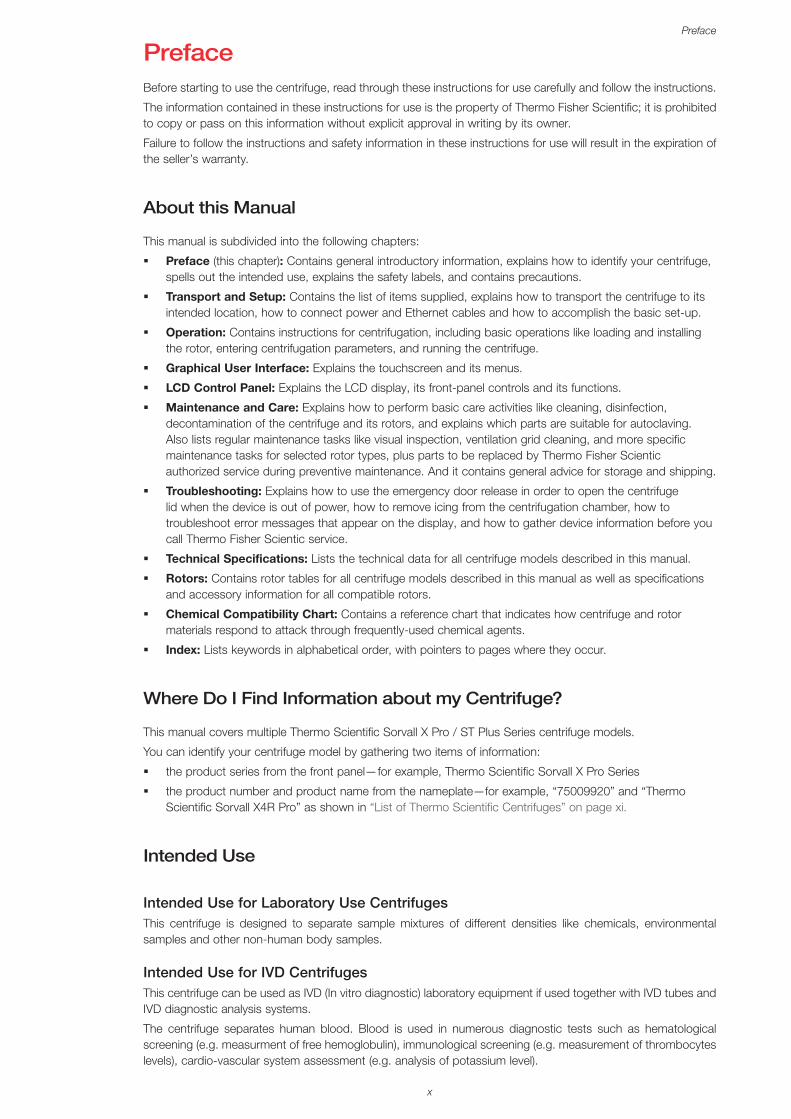
PrefaceBefore starting to use the centrifuge, read through these instructions for use carefully and follow the instructions.
The information contained in these instructions for use is the property of Thermo Fisher Scientific; it is prohibited to copy or pass on this information without explicit approval in writing by its owner.
Failure to follow the instructions and safety information in these instructions for use will result in the expiration of the seller’s warranty.
About this Manual
This manual is subdivided into the following chapters:
� Preface (this chapter): Contains general introductory information, explains how to identify your centrifuge, spells out the intended use, explains the safety labels, and contains precautions.
� Transport and Setup: Contains the list of items supplied, explains how to transport the centrifuge to its intended location, how to connect power and Ethernet cables and how to accomplish the basic set-up.
� Operation: Contains instructions for centrifugation, including basic operations like loading and installing the rotor, entering centrifugation parameters, and running the centrifuge.
� Graphical User Interface: Explains the touchscreen and its menus.
� LCD Control Panel: Explains the LCD display, its front-panel controls and its functions.
� Maintenance and Care: Explains how to perform basic care activities like cleaning, disinfection, decontamination of the centrifuge and its rotors, and explains which parts are suitable for autoclaving. Also lists regular maintenance tasks like visual inspection, ventilation grid cleaning, and more specific maintenance tasks for selected rotor types, plus parts to be replaced by Thermo Fisher Scientic authorized service during preventive maintenance. And it contains general advice for storage and shipping.
� Troubleshooting: Explains how to use the emergency door release in order to open the centrifuge lid when the device is out of power, how to remove icing from the centrifugation chamber, how to troubleshoot error messages that appear on the display, and how to gather device information before you call Thermo Fisher Scientic service.
� Technical Specifications: Lists the technical data for all centrifuge models described in this manual.
� Rotors: Contains rotor tables for all centrifuge models described in this manual as well as specifications and accessory information for all compatible rotors.
� Chemical Compatibility Chart: Contains a reference chart that indicates how centrifuge and rotor materials respond to attack through frequently-used chemical agents.
� Index: Lists keywords in alphabetical order, with pointers to pages where they occur.
Where Do I Find Information about my Centrifuge?
This manual covers multiple Thermo Scientific Sorvall X Pro / ST Plus Series centrifuge models.
You can identify your centrifuge model by gathering two items of information:
� the product series from the front panel—for example, Thermo Scientific Sorvall X Pro Series
� the product number and product name from the nameplate—for example, “75009920” and “Thermo Scientific Sorvall X4R Pro” as shown in “List of Thermo Scientific Centrifuges” on page xi.
Intended Use
Intended Use for Laboratory Use CentrifugesThis centrifuge is designed to separate sample mixtures of different densities like chemicals, environmental samples and other non-human body samples.
Intended Use for IVD CentrifugesThis centrifuge can be used as IVD (In vitro diagnostic) laboratory equipment if used together with IVD tubes and IVD diagnostic analysis systems.
The centrifuge separates human blood. Blood is used in numerous diagnostic tests such as hematological screening (e.g. measurment of free hemoglobulin), immunological screening (e.g. measurement of thrombocytes levels), cardio-vascular system assessment (e.g. analysis of potassium level).
xi
Preface
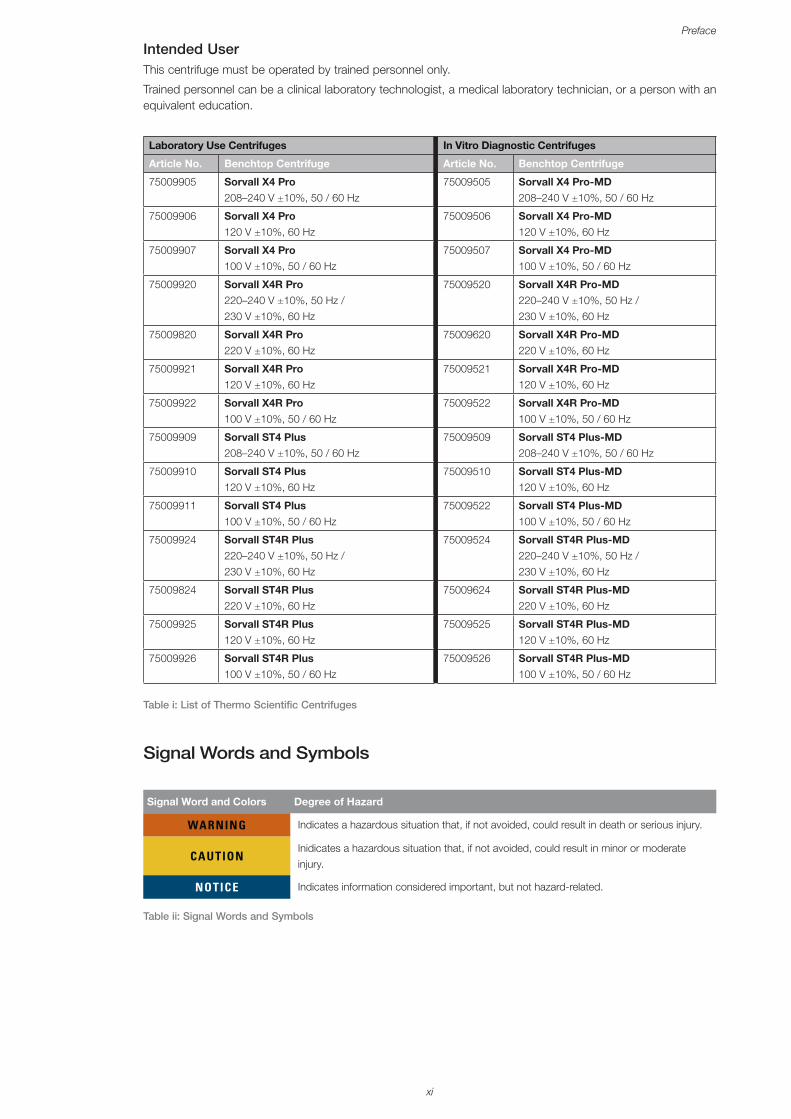
Intended UserThis centrifuge must be operated by trained personnel only.
Trained personnel can be a clinical laboratory technologist, a medical laboratory technician, or a person with an equivalent education.
Laboratory Use Centrifuges In Vitro Diagnostic Centrifuges
Article No. Benchtop Centrifuge Article No. Benchtop Centrifuge
75009905 Sorvall X4 Pro 208–240 V ±10%, 50 / 60 Hz
75009505 Sorvall X4 Pro-MD 208–240 V ±10%, 50 / 60 Hz
75009906 Sorvall X4 Pro 120 V ±10%, 60 Hz
75009506 Sorvall X4 Pro-MD 120 V ±10%, 60 Hz
75009907 Sorvall X4 Pro 100 V ±10%, 50 / 60 Hz
75009507 Sorvall X4 Pro-MD 100 V ±10%, 50 / 60 Hz
75009920 Sorvall X4R Pro
220–240 V ±10%, 50 Hz / 230 V ±10%, 60 Hz
75009520 Sorvall X4R Pro-MD 220–240 V ±10%, 50 Hz / 230 V ±10%, 60 Hz
75009820 Sorvall X4R Pro 220 V ±10%, 60 Hz
75009620 Sorvall X4R Pro-MD 220 V ±10%, 60 Hz
75009921 Sorvall X4R Pro 120 V ±10%, 60 Hz
75009521 Sorvall X4R Pro-MD 120 V ±10%, 60 Hz
75009922 Sorvall X4R Pro 100 V ±10%, 50 / 60 Hz
75009522 Sorvall X4R Pro-MD 100 V ±10%, 50 / 60 Hz
75009909 Sorvall ST4 Plus 208–240 V ±10%, 50 / 60 Hz
75009509 Sorvall ST4 Plus-MD 208–240 V ±10%, 50 / 60 Hz
75009910 Sorvall ST4 Plus 120 V ±10%, 60 Hz
75009510 Sorvall ST4 Plus-MD 120 V ±10%, 60 Hz
75009911 Sorvall ST4 Plus 100 V ±10%, 50 / 60 Hz
75009522 Sorvall ST4 Plus-MD 100 V ±10%, 50 / 60 Hz
75009924 Sorvall ST4R Plus 220–240 V ±10%, 50 Hz / 230 V ±10%, 60 Hz
75009524 Sorvall ST4R Plus-MD 220–240 V ±10%, 50 Hz / 230 V ±10%, 60 Hz
75009824 Sorvall ST4R Plus 220 V ±10%, 60 Hz
75009624 Sorvall ST4R Plus-MD 220 V ±10%, 60 Hz
75009925 Sorvall ST4R Plus 120 V ±10%, 60 Hz
75009525 Sorvall ST4R Plus-MD 120 V ±10%, 60 Hz
75009926 Sorvall ST4R Plus 100 V ±10%, 50 / 60 Hz
75009526 Sorvall ST4R Plus-MD 100 V ±10%, 50 / 60 Hz
Table i: List of Thermo Scientific Centrifuges
Signal Words and Symbols
Signal Word and Colors Degree of Hazard
WARNING Indicates a hazardous situation that, if not avoided, could result in death or serious injury.
CAUTIONInidicates a hazardous situation that, if not avoided, could result in minor or moderate injury.
NOTICE Indicates information considered important, but not hazard-related.
Table ii: Signal Words and Symbols
xii
Preface
Symbols used on Unit and Accessories
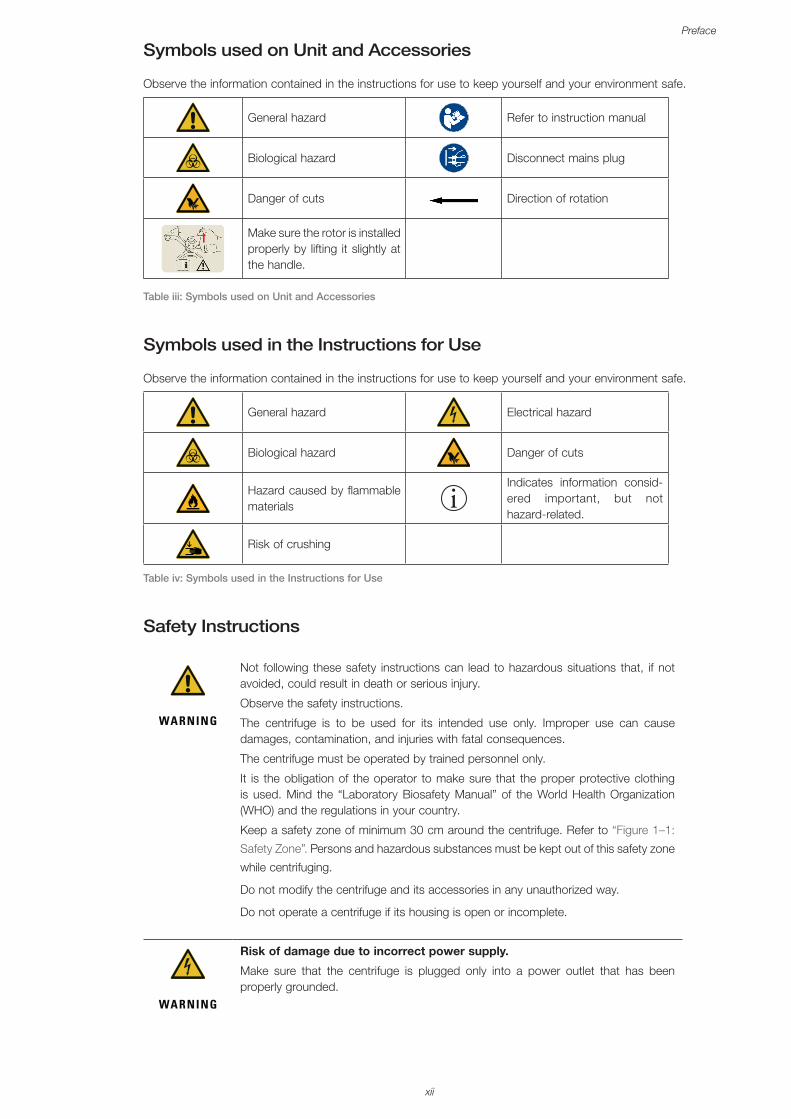
Observe the information contained in the instructions for use to keep yourself and your environment safe.
General hazard Refer to instruction manual
Biological hazard Disconnect mains plug
Danger of cuts Direction of rotation
Make sure the rotor is installed properly by lifting it slightly at the handle.
Table iii: Symbols used on Unit and Accessories
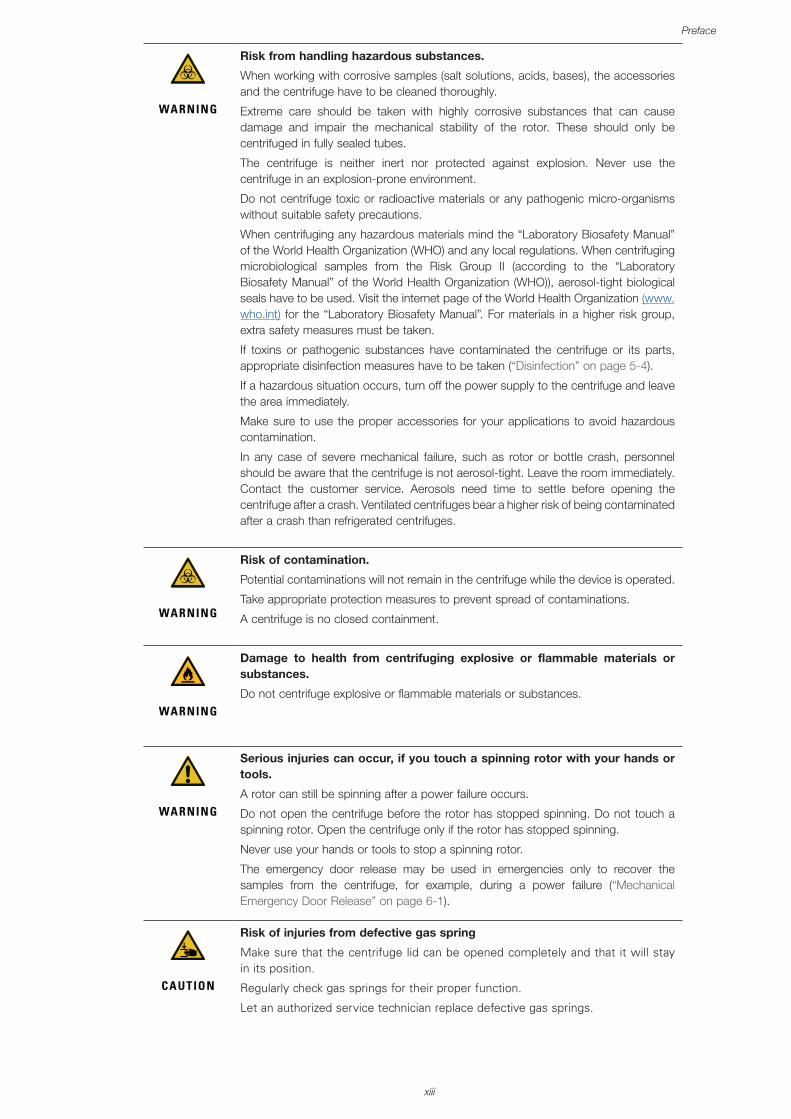
Symbols used in the Instructions for Use
Observe the information contained in the instructions for use to keep yourself and your environment safe.
General hazard Electrical hazard
Biological hazard Danger of cuts
Hazard caused by flammable materials
Indicates information consid-ered important, but not hazard-related.
Risk of crushing
Table iv: Symbols used in the Instructions for Use
Safety Instructions
WARNING
Not following these safety instructions can lead to hazardous situations that, if not avoided, could result in death or serious injury.
Observe the safety instructions.
The centrifuge is to be used for its intended use only. Improper use can cause damages, contamination, and injuries with fatal consequences.
The centrifuge must be operated by trained personnel only.
It is the obligation of the operator to make sure that the proper protective clothing is used. Mind the “Laboratory Biosafety Manual” of the World Health Organization (WHO) and the regulations in your country.
Keep a safety zone of minimum 30 cm around the centrifuge. Refer to “Figure 1–1:
Safety Zone”. Persons and hazardous substances must be kept out of this safety zone
while centrifuging.
Do not modify the centrifuge and its accessories in any unauthorized way.
Do not operate a centrifuge if its housing is open or incomplete.
WARNING
Risk of damage due to incorrect power supply.
Make sure that the centrifuge is plugged only into a power outlet that has been properly grounded.
xiii
Preface
WARNING
Risk from handling hazardous substances.
When working with corrosive samples (salt solutions, acids, bases), the accessories and the centrifuge have to be cleaned thoroughly.
Extreme care should be taken with highly corrosive substances that can cause damage and impair the mechanical stability of the rotor. These should only be centrifuged in fully sealed tubes.
The centrifuge is neither inert nor protected against explosion. Never use the centrifuge in an explosion-prone environment.
Do not centrifuge toxic or radioactive materials or any pathogenic micro-organisms without suitable safety precautions.
When centrifuging any hazardous materials mind the “Laboratory Biosafety Manual” of the World Health Organization (WHO) and any local regulations. When centrifuging microbiological samples from the Risk Group II (according to the “Laboratory Biosafety Manual” of the World Health Organization (WHO)), aerosol-tight biological seals have to be used. Visit the internet page of the World Health Organization (www.who.int) for the “Laboratory Biosafety Manual”. For materials in a higher risk group, extra safety measures must be taken.
If toxins or pathogenic substances have contaminated the centrifuge or its parts, appropriate disinfection measures have to be taken (“Disinfection” on page 5-4).
If a hazardous situation occurs, turn off the power supply to the centrifuge and leave the area immediately.
Make sure to use the proper accessories for your applications to avoid hazardous contamination.
In any case of severe mechanical failure, such as rotor or bottle crash, personnel should be aware that the centrifuge is not aerosol-tight. Leave the room immediately. Contact the customer service. Aerosols need time to settle before opening the centrifuge after a crash. Ventilated centrifuges bear a higher risk of being contaminated after a crash than refrigerated centrifuges.
WARNING
Risk of contamination.
Potential contaminations will not remain in the centrifuge while the device is operated.
Take appropriate protection measures to prevent spread of contaminations.
A centrifuge is no closed containment.
WARNING
Damage to health from centrifuging explosive or flammable materials or substances.
Do not centrifuge explosive or flammable materials or substances.
WARNING
Serious injuries can occur, if you touch a spinning rotor with your hands or tools.
A rotor can still be spinning after a power failure occurs.
Do not open the centrifuge before the rotor has stopped spinning. Do not touch a spinning rotor. Open the centrifuge only if the rotor has stopped spinning.
Never use your hands or tools to stop a spinning rotor.
The emergency door release may be used in emergencies only to recover the samples from the centrifuge, for example, during a power failure (“Mechanical Emergency Door Release” on page 6-1).
CAUTION
Risk of injuries from defective gas spring
Make sure that the centrifuge lid can be opened completely and that it will stay in its position.
Regularly check gas springs for their proper function.
Let an authorized service technician replace defective gas springs.
xiv
Preface
CAUTION
Cutting injuries from broken display glass.
Do not touch a damaged display.
CAUTION
Safety can be impaired by wrong loading and worn accessories.
Always make sure that the load is as equally distributed as possible.
Do not use rotors and accessories which show any signs of corrosion or cracks. Contact customer service for further information.
Do not operate the centrifuge with an unbalanced rotor. Use only rotors which have been loaded properly.
Never overload the rotor.
Make sure that rotors and accessories are installed properly before operating the centrifuge. Follow the instructions in section “How to Install and Remove a Rotor” on page 2-3.
CAUTION
Physical harm caused by ignoring operative basics.
Operate the centrifuge with a properly installed rotor.
Do not move the centrifuge while it is running.
Do not lean on the centrifuge.
Do not put anything on the centrifuge while it is running.
The centrifuge housing is not to be opened by the operator.
NOTICE
Integrity of samples may be affected by heat generation in ventilated centrifuges.
Ventilated units lead to a heat up of the rotor that might cause sample degradation.
NOTICE
Protection capability may be impaired due to using not approved accessories.
Use only accessories for this centrifuge which have been approved by Thermo Fisher Scientific. For a list of approved accessories refer to “Rotor Specifications” on page B-1.
Exceptions to this rule are commercially available glass or plastic centrifuge labware, provided they have been designed to fit in the rotor or the adapter cavities and are approved for the speed or the RCF value of the rotor.
NOTICE
Damage to device or malfunction due to a damaged touch screen.
Do not operate the device
Power off the centrifuge. Disconnect the mains plug. Let an authorized service technician replace the touchscreen.
NOTICE
To shut down the centrifuge:
Press the “Stop” key. Turn off the centrifuge at the main switch. Pull out the power supply plug. In an emergency disconnect the power supply.
Make sure that the main switch and power supply plug can be accessed easily when setting up the centrifuge. The grounded electrical socket should be well accesible and located outside of the safety zone.
1-1
Transport and Set Up
1. Transport and Set Up
NOTICEIt is your responsibility to ensure that all requirements are met for safety reasons.
1. 1. UnpackingThe shipping carton should be inspected upon delivery. When received, carefully examine for any shipping damage before unpacking. If damage is discovered, the delivering carrier should specify and sign for the damage on your copy of the delivery receipt.
Open the carton carefully making certain that all parts (Table 1–1) are accounted for before packaging materials are discarded. Remove the packaging completely. After unpacking, if damage is found, report it to the carrier and request a damage inspection. Dispose of the packaging in accordance with local waste disposal regulations.
Failure to request an inspection of damage within a few days after receipt of shipment absolves the carrier from any liability for damage. You must call for a damage inspection.
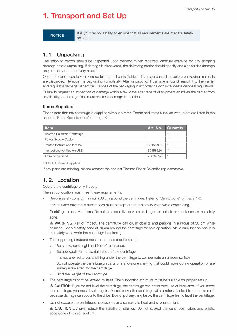
Items SuppliedPlease note that the centrifuge is supplied without a rotor. Rotors and items supplied with rotors are listed in the chapter “Rotor Specifications” on page B-1.
Item Art. No. QuantityThermo Scientific Centrifuge 1
Power Supply Cable 1
Printed Instructions for Use 50158487 1
Instructions for Use on USB 50158526 1
Anti-corrosion oil 70009824 1
Table 1–1: Items Supplied
If any parts are missing, please contact the nearest Thermo Fisher Scientific representative.
1. 2. LocationOperate the centrifuge only indoors.
The set up location must meet these requirements:
� Keep a safety zone of minimum 30 cm around the centrifuge. Refer to “Safety Zone” on page 1-2.
Persons and hazardous substances must be kept out of this safety zone while centrifuging.
Centrifuges cause vibrations. Do not store sensitive devices or dangerous objects or substances in the safety
zone.
A WARNING Risk of impact. The centrifuge can crush objects and persons in a radius of 30 cm while spinning. Keep a safety zone of 30 cm around the centrifuge for safe operation. Make sure that no one is in the safety zone while the centrifuge is spinning.
� The supporting structure must meet these requirements:
» Be stable, solid, rigid and free of resonance.
» Be applicable for horizontal set up of the centrifuge.
It is not allowed to put anything under the centrifuge to compensate an uneven surface.
Do not operate the centrifuge on carts or stand-alone shelving that could move during operation or are inadequately sized for the centrifuge.
» Hold the weight of the centrifuge.
� The centrifuge cannot be leveled by itself. The supporting structure must be suitable for proper set up.
A CAUTION If you do not level the centrifuge, the centrifuge can crash because of imbalance. If you move the centrifuge, you must level it again. Do not move the centrifuge with a rotor attached to the drive shaft because damage can occur to the drive. Do not put anything below the centrifuge feet to level the centrifuge.
� Do not expose the centrifuge, accessories and samples to heat and strong sunlight.
A CAUTION UV rays reduce the stability of plastics. Do not subject the centrifuge, rotors and plastic accessories to direct sunlight.
1-2
Transport and Set Up
� The set up location must be well ventilated at all times.
� The main switch and power supply plug must be easily accessible at all times. The grounded electrical socket should be well accesible and located outside of the safety zone.
Figure 1–1: Safety Zone
1. 3. TransportingBefore transporting a centrifuge make sure that
� the power supply cable is unplugged and removed from the centrifuge.
� the rotor is removed.
A CAUTION Damage to centrifuge or drive shaft due to movement of an installed rotor. Always remove the rotor before you transport the centrifuge.
� the centrifuge door is closed.
A CAUTION Hands can be squeezed by open centrifuge door. Always close the centrifuge door before you transport the centrifuge.
� the centrifuge is lifted at both sides and not at the front or back.
Figure 1–2: Lifting the Centrifuge at Both Sides
A WARNING Always lift the centrifuge on both sides. Never lift the centrifuge by its front or back. The centrifuge is heavy (see “Technical Specifications” on page A-1). Assign a minimum of 4 persons to lift and carry a refrigerated centrifuge. Assign a minimum of 2 persons to lift and carry a ventilated centrifuge.
Before transporting a rotor make sure that
� all components, like adapters and buckets are removed to prevent dropping damage.
1-3
Transport and Set Up
1. 4. Product Overview
1. 4. 1. Refrigerated Benchtop Centrifuges
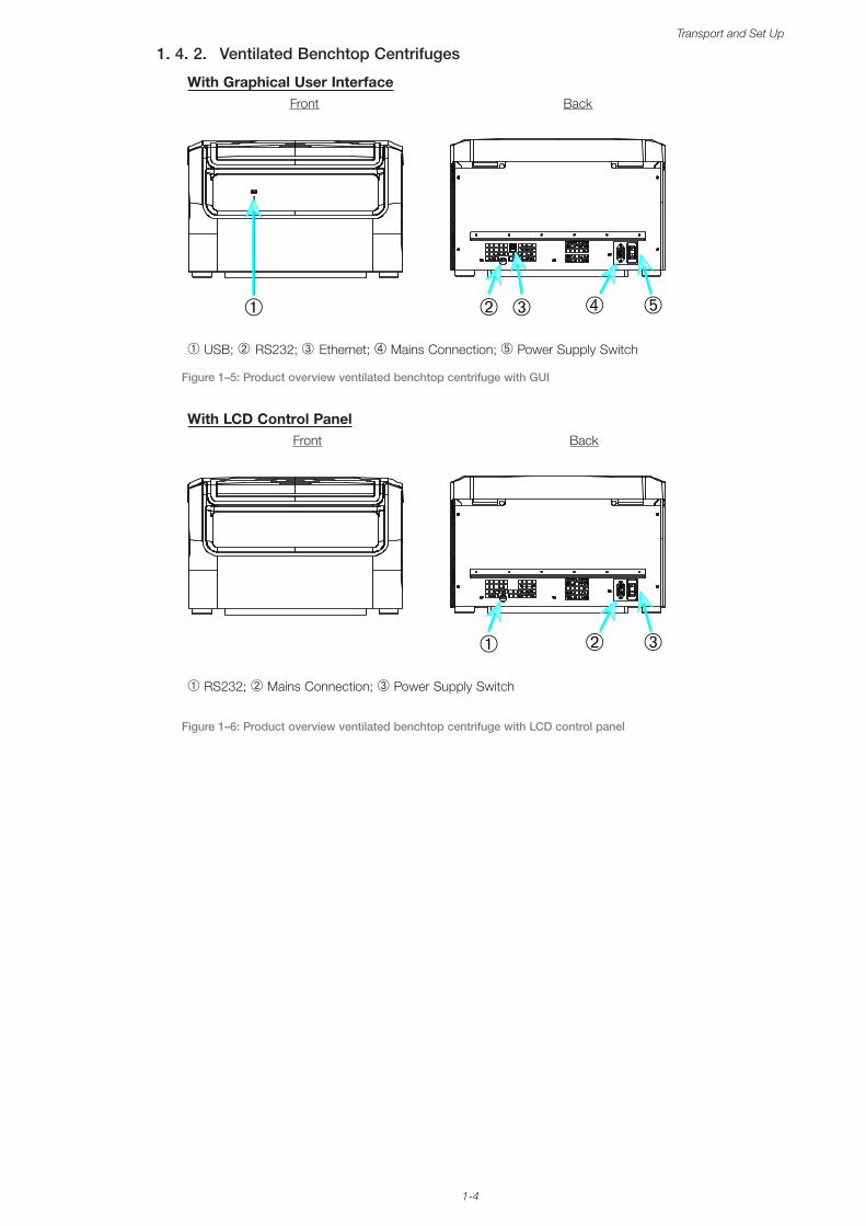
With Graphical User Interface (GUI)Front Back
➃➂ ➄➀ ➁
➀ USB; ➁ RS232; ➂ Ethernet; ➃ Mains Connection; ➄ Power Supply Switch
Figure 1–3: Product overview refrigerated benchtop centrifuge with GUI
With LCD Control PanelFront Back
➁ ➂➀
➀ RS232; ➁ Mains Connection; ➂ Power Supply Switch
Figure 1–4: Product overview refrigerated benchtop centrifuge with LCD control panel
1-4
Transport and Set Up
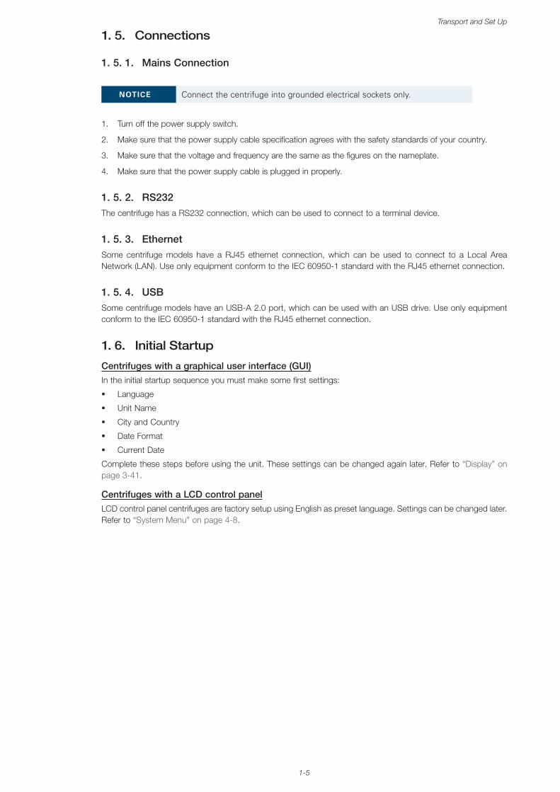
1. 4. 2. Ventilated Benchtop Centrifuges
With Graphical User InterfaceFront Back
➃➂ ➄➀ ➁
➀ USB; ➁ RS232; ➂ Ethernet; ➃ Mains Connection; ➄ Power Supply Switch
Figure 1–5: Product overview ventilated benchtop centrifuge with GUI
With LCD Control PanelFront Back
➁ ➂➀
➀ RS232; ➁ Mains Connection; ➂ Power Supply Switch
Figure 1–6: Product overview ventilated benchtop centrifuge with LCD control panel
1-5
Transport and Set Up
1. 5. Connections
1. 5. 1. Mains Connection
NOTICE Connect the centrifuge into grounded electrical sockets only.
1. Turn off the power supply switch.
2. Make sure that the power supply cable specification agrees with the safety standards of your country.
3. Make sure that the voltage and frequency are the same as the figures on the nameplate.
4. Make sure that the power supply cable is plugged in properly.
1. 5. 2. RS232The centrifuge has a RS232 connection, which can be used to connect to a terminal device.
1. 5. 3. EthernetSome centrifuge models have a RJ45 ethernet connection, which can be used to connect to a Local Area Network (LAN). Use only equipment conform to the IEC 60950-1 standard with the RJ45 ethernet connection.
1. 5. 4. USBSome centrifuge models have an USB-A 2.0 port, which can be used with an USB drive. Use only equipment conform to the IEC 60950-1 standard with the RJ45 ethernet connection.
1. 6. Initial Startup
Centrifuges with a graphical user interface (GUI)In the initial startup sequence you must make some first settings:
� Language
� Unit Name
� City and Country
� Date Format
� Current Date
Complete these steps before using the unit. These settings can be changed again later. Refer to “Display” on page 3-41.
Centrifuges with a LCD control panelLCD control panel centrifuges are factory setup using English as preset language. Settings can be changed later. Refer to “System Menu” on page 4-8.
2-1
Operation
2. Operation
2. 1. Position of parts➀➁➂➃➄
➀
➁
➂
➃
➄
➅
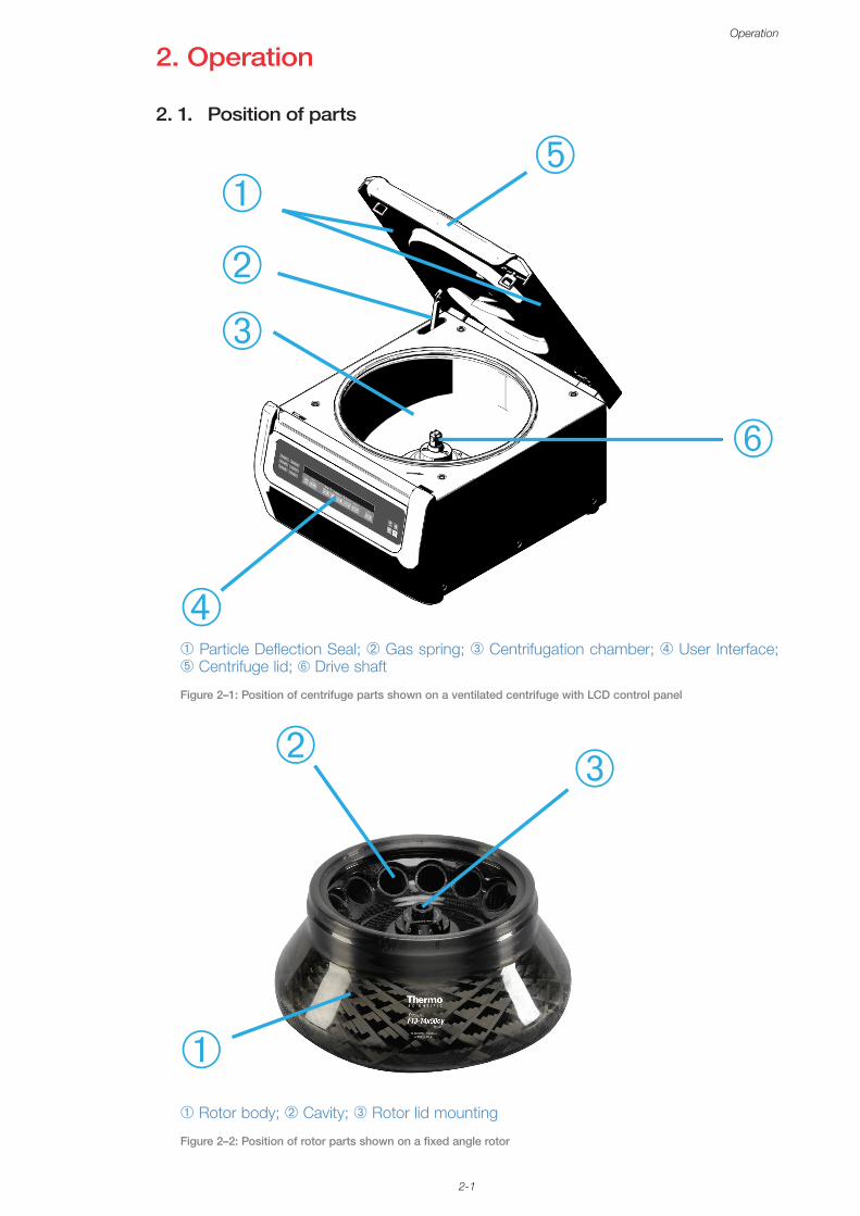
➀ Particle Deflection Seal; ➁ Gas spring; ➂ Centrifugation chamber; ➃ User Interface; ➄ Centrifuge lid; ➅ Drive shaft
Figure 2–1: Position of centrifuge parts shown on a ventilated centrifuge with LCD control panel
➀ Rotor body; ➁ Cavity; ➂ Rotor lid mounting
➀
➁ ➂
Figure 2–2: Position of rotor parts shown on a fixed angle rotor
2-2
Operation
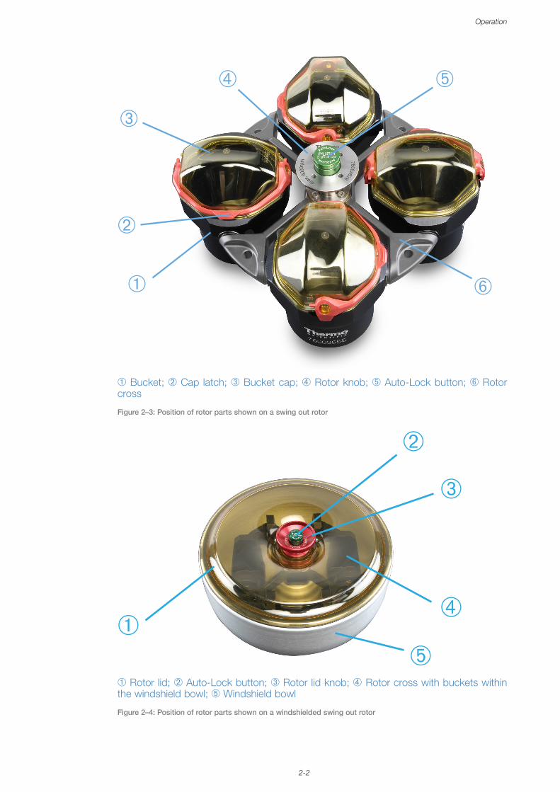
➀ Bucket; ➁ Cap latch; ➂ Bucket cap; ➃ Rotor knob; ➄
➀
➁
➂
➃ ➄
➅
Auto-Lock button; ➅ Rotor cross
Figure 2–3: Position of rotor parts shown on a swing out rotor
➀
➁
➂
➃
➄➀ Rotor lid; ➁ Auto-Lock button; ➂ Rotor lid knob; ➃ Rotor cross with buckets within the windshield bowl; ➄ Windshield bowl
Figure 2–4: Position of rotor parts shown on a windshielded swing out rotor
2-3
Operation
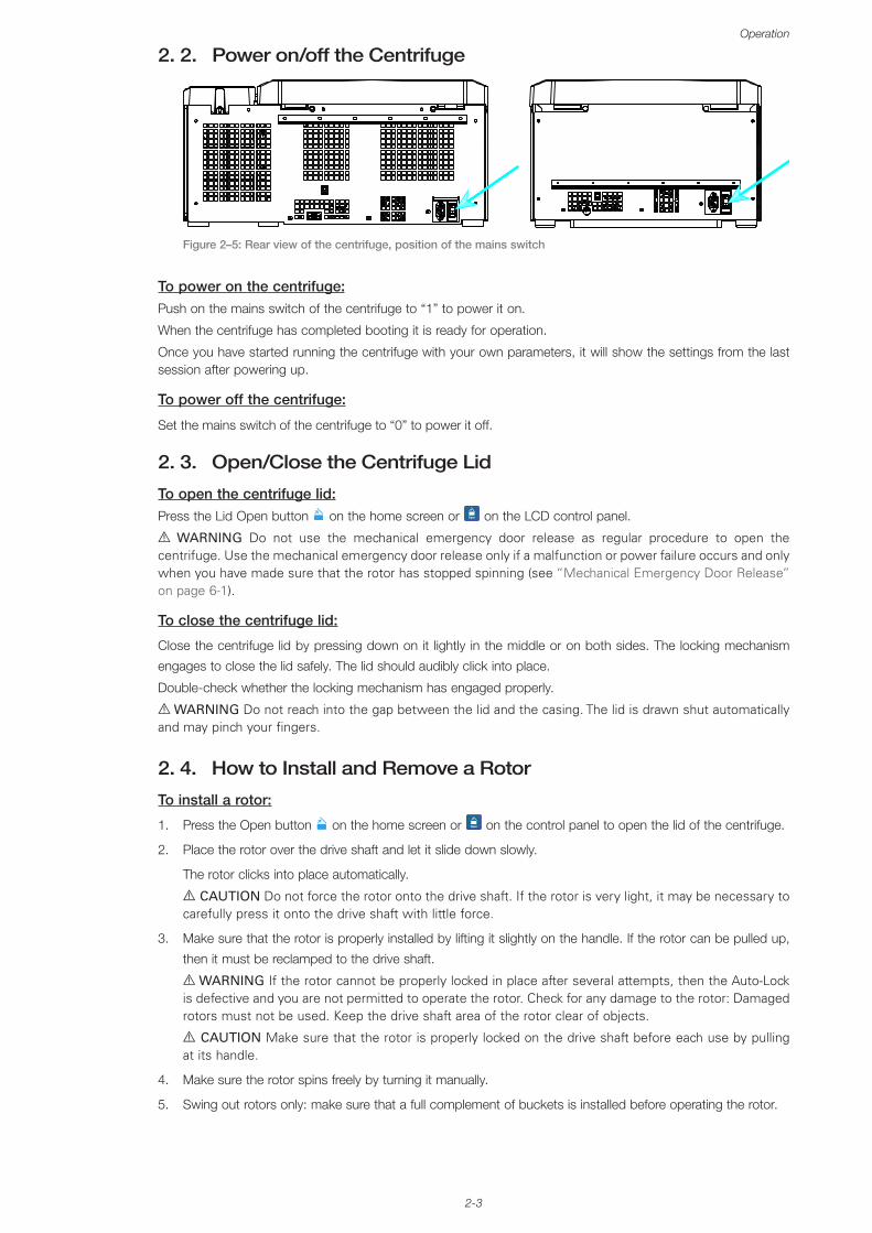
2. 2. Power on/off the Centrifuge
Figure 2–5: Rear view of the centrifuge, position of the mains switch
To power on the centrifuge:Push on the mains switch of the centrifuge to “1” to power it on.
When the centrifuge has completed booting it is ready for operation.
Once you have started running the centrifuge with your own parameters, it will show the settings from the last session after powering up.
To power off the centrifuge:
Set the mains switch of the centrifuge to “0” to power it off.
2. 3. Open/Close the Centrifuge Lid
To open the centrifuge lid:Press the Lid Open button on the home screen or Open on the LCD control panel.
A WARNING Do not use the mechanical emergency door release as regular procedure to open the centrifuge. Use the mechanical emergency door release only if a malfunction or power failure occurs and only when you have made sure that the rotor has stopped spinning (see “Mechanical Emergency Door Release” on page 6-1).
To close the centrifuge lid:
Close the centrifuge lid by pressing down on it lightly in the middle or on both sides. The locking mechanism
engages to close the lid safely. The lid should audibly click into place.
Double-check whether the locking mechanism has engaged properly.
A WARNING Do not reach into the gap between the lid and the casing. The lid is drawn shut automatically and may pinch your fingers.
2. 4. How to Install and Remove a Rotor
To install a rotor:
1. Press the Open button on the home screen or Open on the control panel to open the lid of the centrifuge.
2. Place the rotor over the drive shaft and let it slide down slowly.
The rotor clicks into place automatically.
A CAUTION Do not force the rotor onto the drive shaft. If the rotor is very light, it may be necessary to carefully press it onto the drive shaft with little force.
3. Make sure that the rotor is properly installed by lifting it slightly on the handle. If the rotor can be pulled up,
then it must be reclamped to the drive shaft.
A WARNING If the rotor cannot be properly locked in place after several attempts, then the Auto-Lock is defective and you are not permitted to operate the rotor. Check for any damage to the rotor: Damaged rotors must not be used. Keep the drive shaft area of the rotor clear of objects.
A CAUTION Make sure that the rotor is properly locked on the drive shaft before each use by pulling at its handle.
4. Make sure the rotor spins freely by turning it manually.
5. Swing out rotors only: make sure that a full complement of buckets is installed before operating the rotor.
2-4
Operation
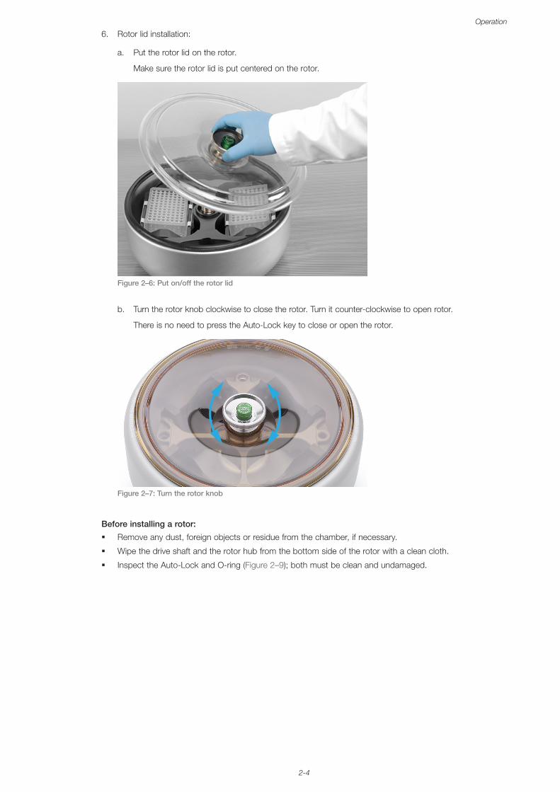
6. Rotor lid installation:
a. Put the rotor lid on the rotor.
Make sure the rotor lid is put centered on the rotor.
Figure 2–6: Put on/off the rotor lid
b. Turn the rotor knob clockwise to close the rotor. Turn it counter-clockwise to open rotor.
There is no need to press the Auto-Lock key to close or open the rotor.
Figure 2–7: Turn the rotor knob
Before installing a rotor:
� Remove any dust, foreign objects or residue from the chamber, if necessary.
� Wipe the drive shaft and the rotor hub from the bottom side of the rotor with a clean cloth.
� Inspect the Auto-Lock and O-ring (Figure 2–9); both must be clean and undamaged.
2-5
Operation
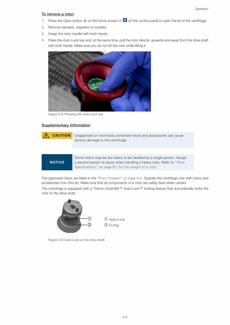
To remove a rotor:
1. Press the Open button on the home screen or Open on the control panel to open the lid of the centrifuge.
2. Remove samples, adapters or buckets.
3. Grasp the rotor handle with both hands.
4. Press the Auto-Lock key and, at the same time, pull the rotor directly upwards and away from the drive shaft
with both hands. Make sure you do not tilt the rotor while lifting it.
Figure 2–8: Pressing the Auto-Lock key
Supplementary Information
CAUTION Unapproved or incorrectly combined rotors and accessories can cause serious damage to the centrifuge.
NOTICESome rotors may be too heavy to be handled by a single person. Assign a second person to assist when handling a heavy rotor. Refer to “Rotor Specifications” on page B-1 for the weight of a rotor.
The approved rotors are listed in the “Rotor Program” on page A-8. Operate the centrifuge only with rotors and accessories from this list. Make sure that all components of a rotor are safely fixed when carried.
The centrifuge is equipped with a Thermo Scientific™ Auto-Lock™ locking feature that automatically locks the rotor to the drive shaft.
➀ Auto-Lock
➁ O-ring
Figure 2–9: Auto-Lock on the drive shaft
2-6
Operation
2. 5. Load the Rotor
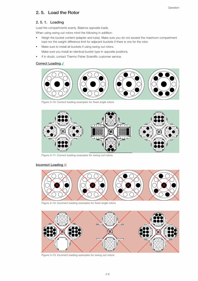
2. 5. 1. LoadingLoad the compartments evenly. Balance opposite loads.
When using swing out rotors mind the following in addition:
� Weigh the bucket content (adapter and tube). Make sure you do not exceed the maximum compartment load nor the weight difference limit for adjacent buckets if there is one for the rotor.
� Make sure to install all buckets if using swing out rotors.
Make sure you install an identical bucket type in opposite positions.
� If in doubt, contact Thermo Fisher Scientific customer service.
Correct Loading ✓
Figure 2–10: Correct loading examples for fixed angle rotors
Figure 2–11: Correct loading examples for swing out rotors
Incorrect Loading ✕
Figure 2–12: Incorrect loading examples for fixed angle rotors
Figure 2–13: Incorrect loading examples for swing out rotors
2-7
Operation
Before loading a Rotor
1. Inspect the rotor and all accessory parts for damage, such as cracks, scratches, or traces of corrosion.
2. Inspect the centrifugation chamber, drive shaft and Auto-Lock device for damage, such as cracks, scratches,
or traces of corrosion.
3. Check the suitability of the rotor and other used accessories against the Chemical Compatibility Chart. Refer
to “Chemical Compatibility” on page C-1.
4. Make sure that:
» tubes or bottles fit in the rotor.
» the tubes or bottles do not touch the rotor lid or bucket caps.
» buckets or microplate carrier can swing freely by moving them carefully with your hand.
CAUTION Incorrect loading can lead to damage. Always load the rotor symmetrically to avoid imbalance, noisy spinning and possible damage. A full complement of buckets needs to be installed before operating a swing out rotor.
CAUTION When using an aerosol-tight rotor lid or bucket caps, verify that the samlple tubes don’t interfere with the rotor lid or bucket cap and don’t compromise its sealing efficiency.
CAUTION Always use 2 identical bucket types in opposite positions. Make sure that opposite buckets are of the same weight class, if a weight class is labeled on the buckets.
2. 5. 2. Maximum LoadingEach rotor is designed to run with its maximum load at maximum speed. The safety system of the centrifuge requires that the rotor is not overloaded.
The rotors are designed to work with substance mixtures with a density of up to 1.2 g/ml. If the admissible maximum load is exceeded, the following steps need to be taken:
� Reduce the fill level.
� Reduce the speed.
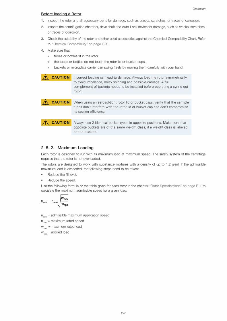
Use the following formula or the table given for each rotor in the chapter “Rotor Specifications” on page B-1 to calculate the maximum admissible speed for a given load:
nadm = admissible maximum application speed
nmax = maximum rated speed
wmax = maximum rated load
wapp = applied load
2-8
Operation
RCF Value ExplainedThe relative centrifugal force (RCF) is given as a multiple of the force of gravity (g). It is a unitless numerical value which is used to compare the separation or sedimentation capacity of various centrifuges, since it is independent of the type of device. Only the centrifuging radius and the speed are used for calculation:
r = centrifuging radius in cm
n = rotational speed in rpm
The maximum RCF value is related to the maximum radius of the tube opening.
Remember that this value is reduced depending on the tubes, buckets and adapters used.
This can be accounted for in the calculation above if required.
2. 5. 3. Use of Tubes and ConsumablesMake sure that the tubes and bottles used in the centrifuge are:
� rated to or above the selected RCF to be spun at,
� used at their minimum fill volume and not above their maximum fill volume,
� not used above their design life (age or number of runs),
� undamaged,
� fitting well into the cavities.
Please refer to manufacturers’ data sheets for further information.
2. 6. Identify Rotor and BucketsThe centrifuge has a rotor detection that identifies an installed rotor. If a swing-out rotor is identified, the centrifuge prompts you to identify the bucket type installed in that rotor.
Rotor detection relies on a list of rotors stored in the memory of the centrifuge. If an unknown rotor is detected, please contact customer service. An update for that rotor list might be available to accommodate new rotor models.
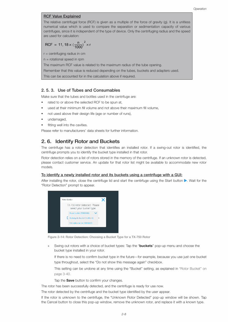
To identify a newly installed rotor and its buckets using a centrifuge with a GUI:After installing the rotor, close the centrifuge lid and start the centirfuge using the Start button . Wait for the “Rotor Detection” prompt to appear.
Figure 2–14: Rotor Detection: Choosing a Bucket Type for a TX-750 Rotor
» Swing out rotors with a choice of bucket types: Tap the “buckets” pop-up menu and choose the bucket type installed in your rotor.
If there is no need to confirm bucket type in the future—for example, because you use just one bucket
type throughout, select the “Do not show this message again” checkbox.
This setting can be undone at any time using the “Bucket” setting, as explained in “Rotor Bucket” on
page 3-40.
Tap the Save button to confirm your changes.
The rotor has been successfully detected, and the centrifuge is ready for use now.
The rotor detected by the centrifuge and the bucket type identified by the user appear.
If the rotor is unknown to the centrifuge, the “Unknown Rotor Detected” pop-up window will be shown. Tap the Cancel button to close this pop-up window, remove the unknown rotor, and replace it with a known type.
2-9
Operation
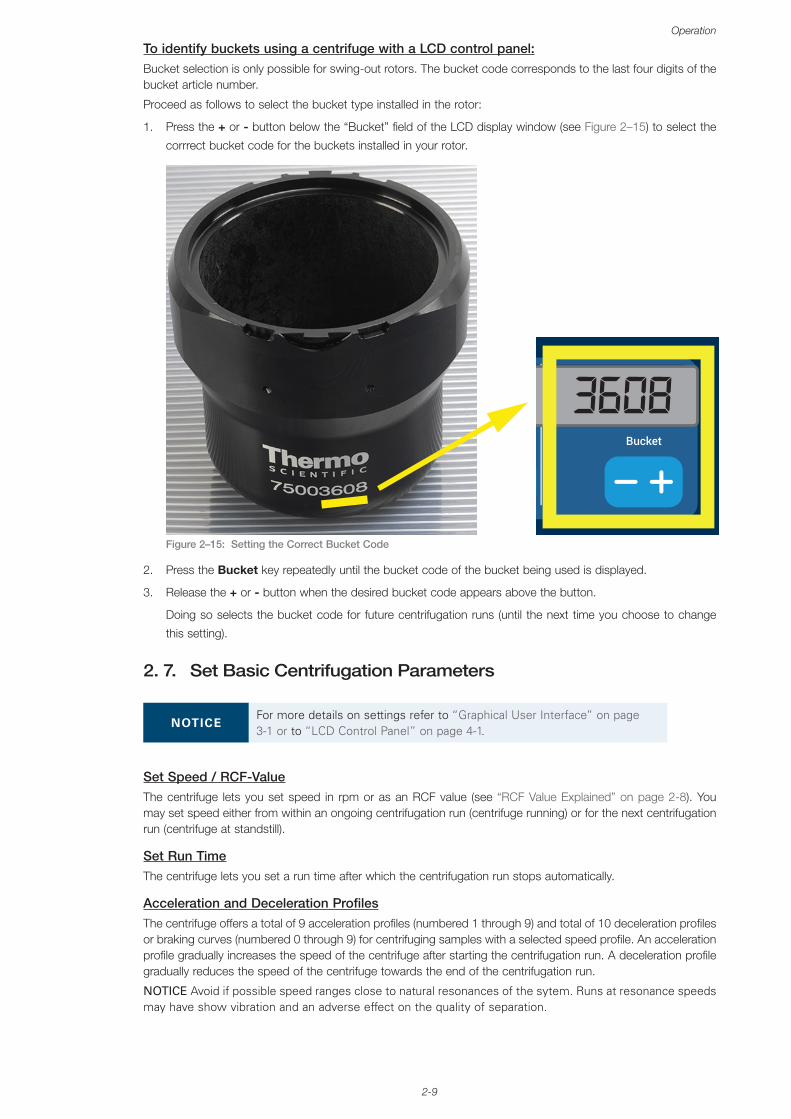
To identify buckets using a centrifuge with a LCD control panel:Bucket selection is only possible for swing-out rotors. The bucket code corresponds to the last four digits of the bucket article number.
Proceed as follows to select the bucket type installed in the rotor:
1. Press the + or - button below the “Bucket” field of the LCD display window (see Figure 2–15) to select the
corrrect bucket code for the buckets installed in your rotor.
Figure 2–15:
9 3608
Setting the Correct Bucket Code
2. Press the Bucket key repeatedly until the bucket code of the bucket being used is displayed.
3. Release the + or - button when the desired bucket code appears above the button.
Doing so selects the bucket code for future centrifugation runs (until the next time you choose to change
this setting).
2. 7. Set Basic Centrifugation Parameters
NOTICEFor more details on settings refer to “Graphical User Interface” on page 3-1 or to “LCD Control Panel” on page 4-1.
Set Speed / RCF-ValueThe centrifuge lets you set speed in rpm or as an RCF value (see “RCF Value Explained” on page 2-8). You may set speed either from within an ongoing centrifugation run (centrifuge running) or for the next centrifugation run (centrifuge at standstill).
Set Run TimeThe centrifuge lets you set a run time after which the centrifugation run stops automatically.
Acceleration and Deceleration ProfilesThe centrifuge offers a total of 9 acceleration profiles (numbered 1 through 9) and total of 10 deceleration profiles or braking curves (numbered 0 through 9) for centrifuging samples with a selected speed profile. An acceleration profile gradually increases the speed of the centrifuge after starting the centrifugation run. A deceleration profile gradually reduces the speed of the centrifuge towards the end of the centrifugation run.
NOTICE Avoid if possible speed ranges close to natural resonances of the sytem. Runs at resonance speeds may have show vibration and an adverse effect on the quality of separation.
2-10
Operation
Set TemperatureA refrigerated centrifuge allows for preselecting a temperature for the sample (GUI versions) or centrifugation chamber temperature (LCD control panel) between -10 °C and +40 °C for the centrifugation run. This feature is not available on ventilated models.
2. 8. Pre-Temper the Centrifugation ChamberRefrigerated centrifuges allow for pre-tempering, that is pre-warming or pre-cooling, the centrifugation chamber and the empty rotor before the centrifugation run starts. If necessary pre-temper your samples using proper equipment. The centrifuge is not intended to be used to pre-temper your samples.
NOTICE Ventilated models cannot pre-temper the centrifugation chamber.
2. 9. Centrifugation
WARNING Damage to health from centrifuging explosive or flammable materials or substances. Do not centrifuge explosive or flammable materials or substances.
CAUTION Due to air friction the temperature of the rotor may rise significantly while the centrifuge is spinning. Displayed and set temperature can deviate from sample temperature. Sample temperature might exceed critical temperature of your apllication.
Mind the safety zone of minimum 30 cm around the centrifuge. Refer to “Safety Zone” on page 1-2. Persons
and hazardous substances must be kept out of this safety zone while centrifuging.
Once the main switch has been turned on, the rotor has been properly installed, the setpoints have been set as explained in the previous section, and the centrifuge lid has been closed, you are ready to start.
You have various options to start a centrifugation run with a GUI: � Continuous Mode: This is a fully manual mode. If you have chosen Continuous Mode instead of a preset
runtime (see “Set Run Time” on page 3-8), use the Start button and Stop button to start and stop centrifugation manually, as explained in the section “Run in Continuous or Timed Mode” on page 3-12 further below.
� Timed Mode: This is a semi-automatic mode that relies on a timer. If you have preset a runtime (see “Set Run Time” on page 3-8), tap the Start button , then and wait for the timer to expire and the centrifuge to stop automatically, as explained in the section “Run in Continuous or Timed Mode” on page 3-12.
� Pulse Mode: This is a short-run centrifugation mode with selectable behaviors. You choose a behavior, then tap the Pulse button and wait for the centrifuge to run and stop automatically, as explained in the section “Run in Pulse Mode” on page 3-13.
� Program Mode: This is a fully automatic mode. You prepare and save an automated program, then run it from the touchscreen, as explained in the section “Automate Processes Using Programs” on page 3-20.
NOTICEFor more details on settings refer to “Graphical User Interface” on page 3-1.
You have various options to start a centrifugation run with a LCD control panel:
� Continuous Mode: This is a fully manual mode. In Continuous Mode you use the Start key Start and Stop
key Stop to start and stop centrifugation manually, as explained in the section “Continuous Operation” further below.
� Timed Mode: This is a semi-automatic mode that relies on a timer. If you have preset a runtime (see “4.
2. 2. Set Run Time” on page 4-3), you press the Start key Start , then wait for the timer to expire and the centrifuge to stop down automatically.
� Program Mode: This is a fully automatic mode. You prepare and save an automated program, as explained in the section “Setting Up and Saving a Program” on page 4-6, then run it by pressing the
appropriate program selection key Program 1 .
NOTICE For more details on settings refer to “LCD Control Panel” on page 4-1.
2-11
Operation
2. 10. Aerosol-Tight Applications
2. 10. 1. Basic PrinciplesMake sure that the sample containers are well suited for the desired centrifugation process.
CAUTION Aerosol-tight rotors and tubes may only be opened in an approved safety work-bench when centrifuging dangerous samples. Mind the maximum permissible load.
CAUTION Be sure to check all sealings before starting any aerosol-tight applications.
2. 10. 2. Fill LevelDo not fill the tubes beyond a safe level to prevent the sample from reaching the top of the tube during centrifugation. To be on the safe side, fill the tubes only to 2/3 of the rated level.
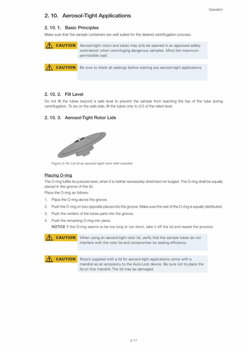
2. 10. 3. Aerosol-Tight Rotor Lids
Figure 2–16: Lid of an aerosol-tight rotor with mandrel
Placing O-ringThe O-ring fullfils its purpose best, when it is neither excessivley stretched nor bulged. The O-ring shall be equally placed in the groove of the lid.
Place the O-ring as follows:
1. Place the O-ring above the groove.
2. Push the O-ring on two opposite places into the groove. Make sure the rest of the O-ring is equally distributed.
3. Push the centers of the loose parts into the groove.
4. Push the remaining O-ring into place.
NOTICE If the O-ring seems to be too long or too short, take it off the lid and repeat the process.
CAUTION When using an aerosol-tight rotor lid, verify that the sample tubes do not interfere with the rotor lid and compromise its sealing efficiency.
CAUTION Rotors supplied with a lid for aerosol-tight applications come with a mandrel as an accessory to the Auto-Lock device. Be sure not to place the lid on this mandrel. The lid may be damaged.
2-12
Operation
2. 10. 4. Aerosol-Tight Rotor Buckets
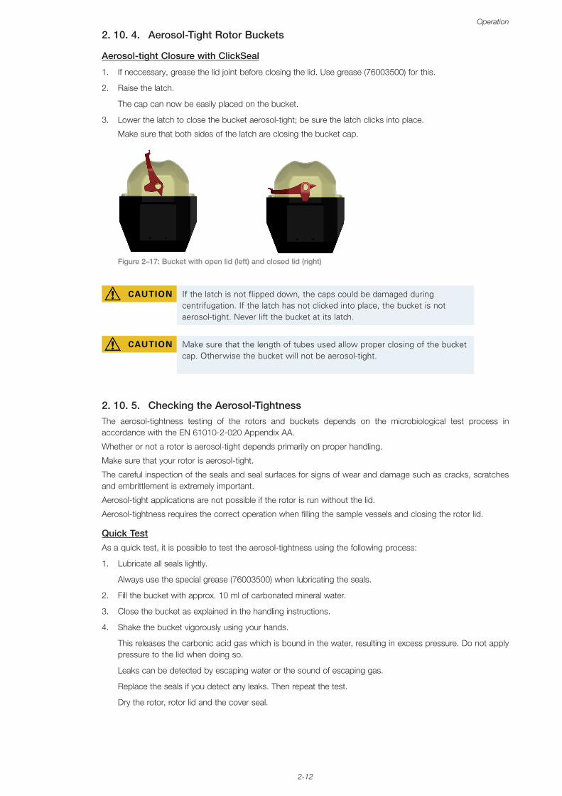
Aerosol-tight Closure with ClickSeal
1. If neccessary, grease the lid joint before closing the lid. Use grease (76003500) for this.
2. Raise the latch.
The cap can now be easily placed on the bucket.
3. Lower the latch to close the bucket aerosol-tight; be sure the latch clicks into place.
Make sure that both sides of the latch are closing the bucket cap.
Figure 2–17: Bucket with open lid (left) and closed lid (right)
CAUTION If the latch is not flipped down, the caps could be damaged during centrifugation. If the latch has not clicked into place, the bucket is not aerosol-tight. Never lift the bucket at its latch.
CAUTION Make sure that the length of tubes used allow proper closing of the bucket cap. Otherwise the bucket will not be aerosol-tight.
2. 10. 5. Checking the Aerosol-TightnessThe aerosol-tightness testing of the rotors and buckets depends on the microbiological test process in accordance with the EN 61010-2-020 Appendix AA.
Whether or not a rotor is aerosol-tight depends primarily on proper handling.
Make sure that your rotor is aerosol-tight.
The careful inspection of the seals and seal surfaces for signs of wear and damage such as cracks, scratches and embrittlement is extremely important.
Aerosol-tight applications are not possible if the rotor is run without the lid.
Aerosol-tightness requires the correct operation when filling the sample vessels and closing the rotor lid.
Quick TestAs a quick test, it is possible to test the aerosol-tightness using the following process:
1. Lubricate all seals lightly.
Always use the special grease (76003500) when lubricating the seals.
2. Fill the bucket with approx. 10 ml of carbonated mineral water.
3. Close the bucket as explained in the handling instructions.
4. Shake the bucket vigorously using your hands.
This releases the carbonic acid gas which is bound in the water, resulting in excess pressure. Do not apply pressure to the lid when doing so.
Leaks can be detected by escaping water or the sound of escaping gas.
Replace the seals if you detect any leaks. Then repeat the test.
Dry the rotor, rotor lid and the cover seal.

2-13
Operation
A CAUTION Prior to each use, the seals in the rotor are to be inspected in order to assure that they are correctly seated and are not worn or damaged. Damaged seals are to be replaced immediately. Replacement seals can be re-ordered as a spare part (“Rotor Specifications” on page B-1). When loading the rotor, ensure that the rotor lid closes securely. Damaged rotor covers are to be replaced immediately.
CAUTION This quick test is not suited for validating the aerosol tightness of a rotor. Check the seals and sealing surfaces of the lid thoroughly.
3-1
Graphical User Interface
3. Graphical User InterfaceThis chapter contains details for centrifuges with the graphical user interface described in this manual. Pictures shown are examples and may be different in details to your experience – for example the home screen for a ventilated unit does not feature an on-screen button entry for entering temperature.
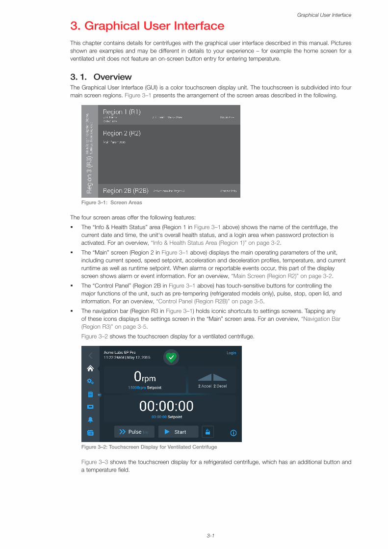
3. 1. OverviewThe Graphical User Interface (GUI) is a color touchscreen display unit. The touchscreen is subdivided into four main screen regions. Figure 3–1 presents the arrangement of the screen areas described in the following.
Figure 3–1: Screen Areas
The four screen areas offer the following features:
� The “Info & Health Status” area (Region 1 in Figure 3–1 above) shows the name of the centrifuge, the current date and time, the unit‘s overall health status, and a login area when password protection is activated. For an overview, “Info & Health Status Area (Region 1)” on page 3-2.
� The “Main” screen (Region 2 in Figure 3–1 above) displays the main operating parameters of the unit, including current speed, speed setpoint, acceleration and deceleration profiles, temperature, and current runtime as well as runtime setpoint. When alarms or reportable events occur, this part of the display screen shows alarm or event information. For an overview, “Main Screen (Region R2)” on page 3-2.
� The “Control Panel” (Region 2B in Figure 3–1 above) has touch-sensitive buttons for controlling the major functions of the unit, such as pre-tempering (refrigerated models only), pulse, stop, open lid, and information. For an overview, “Control Panel (Region R2B)” on page 3-5.
� The navigation bar (Region R3 in Figure 3–1) holds iconic shortcuts to settings screens. Tapping any of these icons displays the settings screen in the “Main” screen area. For an overview, “Navigation Bar (Region R3)” on page 3-5.
Figure 3–2 shows the touchscreen display for a ventilated centrifuge.
Figure 3–2: Touchscreen Display for Ventilated Centrifuge
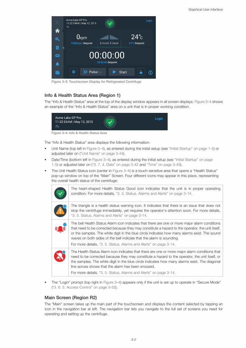
Figure 3–3 shows the touchscreen display for a refrigerated centrifuge, which has an additional button and a temperature field.
3-2
Graphical User Interface
Figure 3–3: Touchscreen Display for Refrigerated Centrifuge
Info & Health Status Area (Region 1)The “Info & Health Status” area at the top of the display window appears in all screen displays. Figure 3–4 shows an example of the “Info & Health Status” area on a unit that is in proper working condition.
Figure 3–4: Info & Health Status Area
The “Info & Health Status” area displays the following information:
� Unit Name (top left in Figure 3–4), as entered during the initial setup (see “Initial Startup” on page 1-5) or adjusted later on (“Unit Name” on page 3-44).
� Date/Time (bottom left in Figure 3–4), as entered during the initial setup (see “Initial Startup” on page 1-5) or adjusted later on (“3. 7. 4. Date” on page 3-42 and “Time” on page 3-43).
� The Unit Health Status icon (center in Figure 3–4) is a touch-sensitive area that opens a “Health Status” pop-up window on top of the “Main” Screen. Four different icons may appear in this place, representing the overall health status of the centrifuge:
The heart-shaped Health Status Good icon indicates that the unit is in proper operating condition. For more details, “3. 5. Status, Alarms and Alerts” on page 3-14.
The triangle is a health status warning icon. It indicates that there is an issue that does not stop the centrifuge immediately, yet requires the operator‘s attention soon. For more details, “3. 5. Status, Alarms and Alerts” on page 3-14.
The bell Health Status Alarm icon indicates that there are one or more major alarm conditions that need to be corrected because they may constitute a hazard to the operator, the unit itself, or the samples. The white digit in the blue circle indicates how many alarms exist. The sound waves on both sides of the bell indicate that the alarm is sounding.
For more details, “3. 5. Status, Alarms and Alerts” on page 3-14.
The Health Status Alarm icon indicates that there are one or more major alarm conditions that need to be corrected because they may constitute a hazard to the operator, the unit itself, or the samples. The white digit in the blue circle indicates how many alarms exist. The diagonal line across shows that the alarm has been snoozed.
For more details, “3. 5. Status, Alarms and Alerts” on page 3-14.
� The “Login” prompt (top right in Figure 3–4) appears only if the unit is set up to operate in “Secure Mode” (“3. 6. 3. Access Control” on page 3-32).
Main Screen (Region R2)The “Main” screen takes up the main part of the touchscreen and displays the content selected by tapping an icon in the navigation bar at left. The navigation bar lets you navigate to the full set of screens you need for operating and setting up the centrifuge.
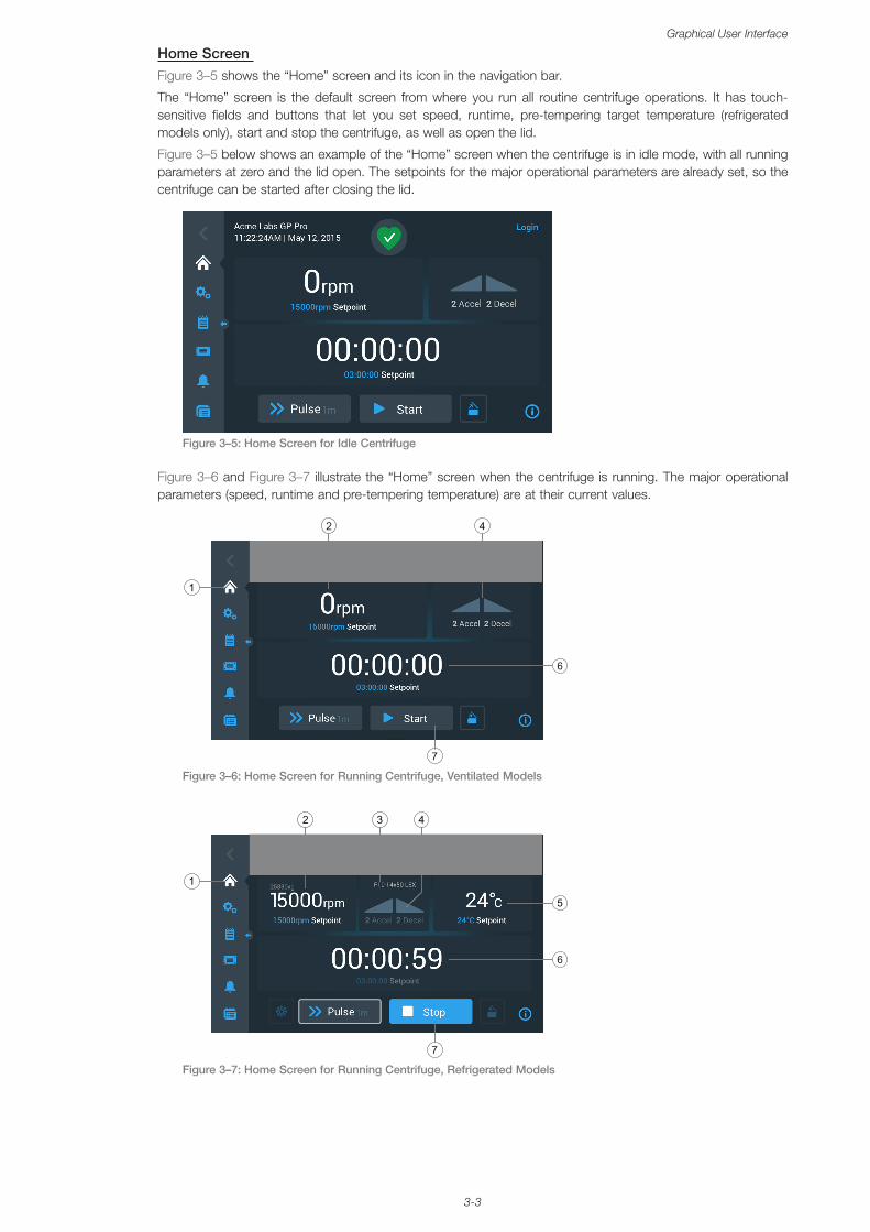
3-3
Graphical User Interface
Home Screen Figure 3–5 shows the “Home” screen and its icon in the navigation bar.
The “Home” screen is the default screen from where you run all routine centrifuge operations. It has touch-sensitive fields and buttons that let you set speed, runtime, pre-tempering target temperature (refrigerated models only), start and stop the centrifuge, as well as open the lid.
Figure 3–5 below shows an example of the “Home” screen when the centrifuge is in idle mode, with all running parameters at zero and the lid open. The setpoints for the major operational parameters are already set, so the centrifuge can be started after closing the lid.
Figure 3–5: Home Screen for Idle Centrifuge
Figure 3–6 and Figure 3–7 illustrate the “Home” screen when the centrifuge is running. The major operational parameters (speed, runtime and pre-tempering temperature) are at their current values.
Figure 3–6: Home Screen for Running Centrifuge, Ventilated Models
Figure 3–7: Home Screen for Running Centrifuge, Refrigerated Models
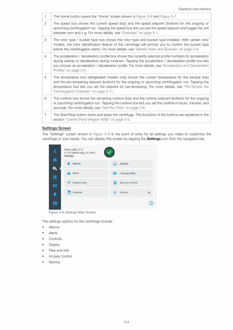
3-4
Graphical User Interface
1 The Home button opens the “Home” screen shown in Figure 3–6 and Figure 3–7.
2 The speed box shows the current speed (top) and the speed setpoint (bottom) for the ongoing or upcoming centrifugation run. Tapping the speed box lets you set the speed setpoint and toggle the unit between rpm and x g. For more details, see “Overview” on page 3-1.
3 The rotor type / bucket type box shows the rotor type and bucket type installed. With certain rotor models, the rotor identification feature of the centrifuge will prompt you to confirm the bucket type before the centrifugation starts. For more details, see “Identify Rotor and Buckets” on page 2-8.
4 The acceleration / deceleration profile box shows the currently selected profile numbers for acceleration during startup or deceleration during rundown. Tapping the acceleration / deceleration profile box lets you choose an acceleration / deceleration profile. For more details, see “Acceleration and Deceleration Profiles” on page 3-9 .
5 The temperature box (refrigerated models only) shows the current temperature for the sample (top) and the pre-tempering setpoint (bottom) for the ongoing or upcoming centrifugation run. Tapping the temperature box lets you set the setpoint for pre-tempering. For more details, see “Pre-Temper the Centrifugation Chamber” on page 3-11.
6 The runtime box shows the remaining runtime (top) and the runtime setpoint (bottom) for the ongoing or upcoming centrifugation run. Tapping the runtime box lets you set the runtime in hours, minutes, and seconds. For more details, see “Set Run Time” on page 3-8.
7 The Start/Stop button starts and stops the centrifuge. The functions of the buttons are explained in the section “Control Panel (Region R2B)” on page 3-5.
Settings ScreenThe “Settings” screen shown in Figure 3–8 is the point of entry for all settings you make to customize the centrifuge to your needs. You can display this screen by tapping the Settings icon from the navigation bar.
Figure 3–8: Settings Main Screen
The settings options for the centrifuge include:
� Alarms
� Alerts
� Controls
� Display
� Files and Info
� Access Control
� Service
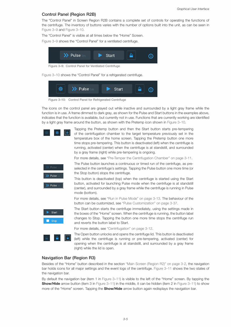
3-5
Graphical User Interface
Control Panel (Region R2B)The “Control Panel” in Screen Region R2B contains a complete set of controls for operating the functions of the centrifuge. The inventory of buttons varies with the number of options built into the unit, as can be seen in Figure 3–9 and Figure 3–10.
The “Control Panel” is visible at all times below the “Home” Screen.
Figure 3–9 shows the “Control Panel” for a ventilated centrifuge.
Figure 3–9: Control Panel for Ventilated Centrifuge
Figure 3–10 shows the “Control Panel” for a refrigerated centrifuge.
Figure 3–10: Control Panel for Refrigerated Centrifuge
The icons on the control panel are grayed out while inactive and surrounded by a light gray frame while the function is in use. A frame dimmed to dark gray, as shown for the Pulse and Start buttons in the examples above, indicates that the function is available, but currently not in use. Functions that are currently working are identified by a light gray frame around the button, as shown with the Pretemp icon shown in Figure 3–10.
Tapping the Pretemp button and then the Start button starts pre-tempering of the centrifugation chamber to the target temperature previously set in the temperature box of the home screen. Tapping the Pretemp button one more time stops pre-tempering. This button is deactivated (left) when the centrifuge is running, activated (center) when the centrifuge is at standstill, and surrounded by a gray frame (right) while pre-tempering is ongoing.
For more details, see “Pre-Temper the Centrifugation Chamber” on page 3-11.
The Pulse button launches a continuous or timed run of the centrifuge, as pre-selected in the centrifuge’s settings. Tapping the Pulse button one more time (or the Stop button) stops the centrifuge.
This button is deactivated (top) when the centrifuge is started using the Start button, activated for launching Pulse mode when the centrifuge is at standstill (center), and surrounded by a gray frame while the centrifuge is running in Pulse mode (bottom).
For more details, see “Run in Pulse Mode” on page 3-13. The behaviour of the button can be customized, see “Pulse Customization” on page 3-37.
The Start button starts the centrifuge immediately, using the settings made in the boxes of the “Home” screen. When the centrifuge is running, the button label changes to Stop. Tapping the button one more time stops the centrifuge run and reverts the button label to Start.
For more details, see “Centrifugation” on page 3-12.
The Open button unlocks and opens the centrifuge lid. This button is deactivated (left) while the centrifuge is running or pre-tempering, activated (center) for opening when the centrifuge is at standstill, and surrounded by a gray frame (right) while the lid is open.
Navigation Bar (Region R3)Besides of the “Home” button described in the section “Main Screen (Region R2)” on page 3-2, the navigation bar holds icons for all major settings and the event logs of the centrifuge. Figure 3–11 shows the two states of the navigation bar.
By default the navigation bar (item 1 in Figure 3–11) is visible to the left of the “Home” screen. By tapping the Show/Hide arrow button (item 3 in Figure 3–11) in the middle, it can be hidden (item 2 in Figure 3–11) to show more of the “Home” screen. Tapping the Show/Hide arrow button again redisplays the navigation bar.
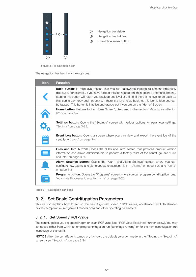
3-6
Graphical User Interface
➀
➁
➂
Navigation bar visible
Navigation bar hidden
Show/Hide arrow button
Figure 3–11: Navigation bar
The navigation bar has the following icons:
Icon Function
Back button: In multi-level menus, lets you run backwards through all screens previously displayed. For example, if you have tapped the Settings button, then opened another submenu, tapping this button will return you back up one level at a time. If there is no level to go back to, this icon is dark gray and not active. If there is a level to go back to, this icon is blue and can be tapped. This button is inactive and grayed out if you are on the “Home” Screen.
Home button: Returns to the “Home Screen”, discussed in the section “Main Screen (Region R2)” on page 3-2.
Settings button: Opens the “Settings” screen with various options for parameter settings; “Settings” on page 3-29.
Event Log button: Opens a screen where you can view and export the event log of the centrifuge; “Logs” on page 3-44
Files and Info button: Opens the “Files and Info” screen that provides product version information and allows administrators to perform a factory reset of the centrifuge; see “Files and Info” on page 3-50
Alarm Settings button: Opens the “Alarm and Alerts Settings” screen where you can configure how alarms and alerts appear on screen; “3. 6. 1. Alarms” on page 3-29 and “Alerts” on page 3-31
Programs button: Opens the “Programs” screen where you can program centrifugation runs; “Automate Processes Using Programs” on page 3-20.
Table 3–1: Navigation bar icons
3. 2. Set Basic Centrifugation ParametersThis section explains how to set up the centrifuge with speed / RCF values, acceleration and deceleration profiles, temperature (refrigerated models only) and other operating parameters.
3. 2. 1. Set Speed / RCF-ValueThe centrifuge lets you set speed in rpm or as an RCF value (see “RCF Value Explained” further below). You may set speed either from within an ongoing centrifugation run (centrifuge running) or for the next centrifugation run (centrifuge at standstill).
NOTICE After the centrifuge is turned on, it shows the default selection made in the “Settings -> Setpoints” screen; see “Setpoints” on page 3-34.
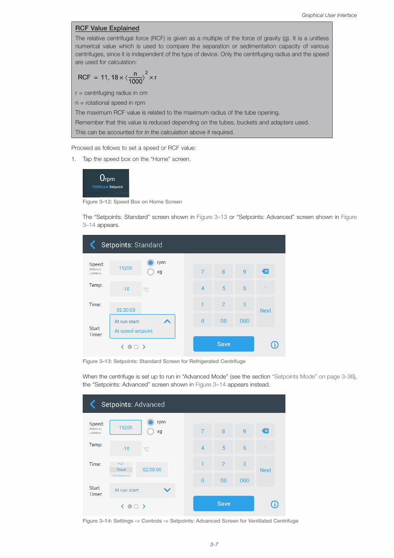
3-7
Graphical User Interface
RCF Value ExplainedThe relative centrifugal force (RCF) is given as a multiple of the force of gravity (g). It is a unitless numerical value which is used to compare the separation or sedimentation capacity of various centrifuges, since it is independent of the type of device. Only the centrifuging radius and the speed are used for calculation:
r = centrifuging radius in cm
n = rotational speed in rpm
The maximum RCF value is related to the maximum radius of the tube opening.
Remember that this value is reduced depending on the tubes, buckets and adapters used.
This can be accounted for in the calculation above if required.
Proceed as follows to set a speed or RCF value:
1. Tap the speed box on the “Home” screen.
Figure 3–12: Speed Box on Home Screen
The “Setpoints: Standard” screen shown in Figure 3–13 or “Setpoints: Advanced” screen shown in Figure 3–14 appears.
Figure 3–13: Setpoints: Standard Screen for Refrigerated Centrifuge
When the centrifuge is set up to run in “Advanced Mode” (see the section “Setpoints Mode” on page 3-36), the “Setpoints: Advanced” screen shown in Figure 3–14 appears instead.
Figure 3–14: Settings -> Controls -> Setpoints: Advanced Screen for Ventilated Centrifuge
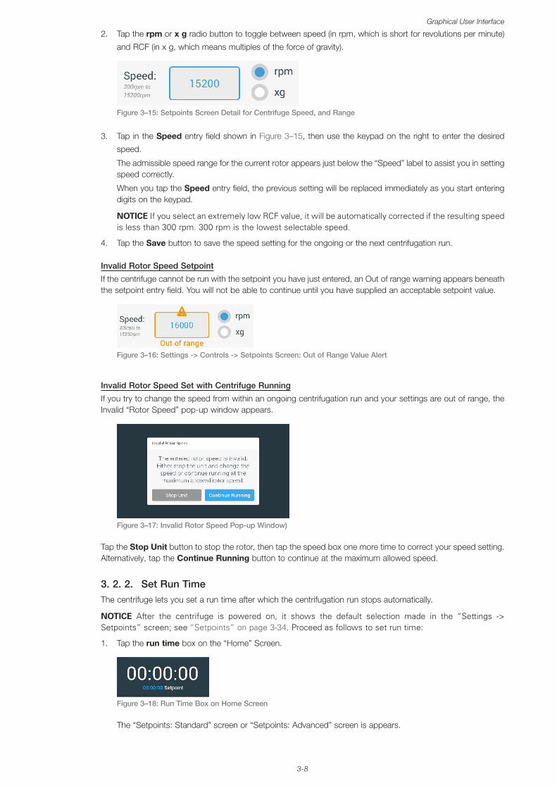
3-8
Graphical User Interface
2. Tap the rpm or x g radio button to toggle between speed (in rpm, which is short for revolutions per minute)
and RCF (in x g, which means multiples of the force of gravity).
Figure 3–15: Setpoints Screen Detail for Centrifuge Speed, and Range
3. Tap in the Speed entry field shown in Figure 3–15, then use the keypad on the right to enter the desired
speed.
The admissible speed range for the current rotor appears just below the “Speed” label to assist you in setting speed correctly.
When you tap the Speed entry field, the previous setting will be replaced immediately as you start entering digits on the keypad.
NOTICE If you select an extremely low RCF value, it will be automatically corrected if the resulting speed is less than 300 rpm. 300 rpm is the lowest selectable speed.
4. Tap the Save button to save the speed setting for the ongoing or the next centrifugation run.
Invalid Rotor Speed Setpoint
If the centrifuge cannot be run with the setpoint you have just entered, an Out of range warning appears beneath the setpoint entry field. You will not be able to continue until you have supplied an acceptable setpoint value.
Figure 3–16: Settings -> Controls -> Setpoints Screen: Out of Range Value Alert
Invalid Rotor Speed Set with Centrifuge Running
If you try to change the speed from within an ongoing centrifugation run and your settings are out of range, the Invalid “Rotor Speed” pop-up window appears.
Figure 3–17: Invalid Rotor Speed Pop-up Window)
Tap the Stop Unit button to stop the rotor, then tap the speed box one more time to correct your speed setting. Alternatively, tap the Continue Running button to continue at the maximum allowed speed.
3. 2. 2. Set Run TimeThe centrifuge lets you set a run time after which the centrifugation run stops automatically.
NOTICE After the centrifuge is powered on, it shows the default selection made in the “Settings -> Setpoints” screen; see “Setpoints” on page 3-34. Proceed as follows to set run time:
1. Tap the run time box on the “Home” Screen.
Figure 3–18: Run Time Box on Home Screen
The “Setpoints: Standard” screen or “Setpoints: Advanced” screen is appears.
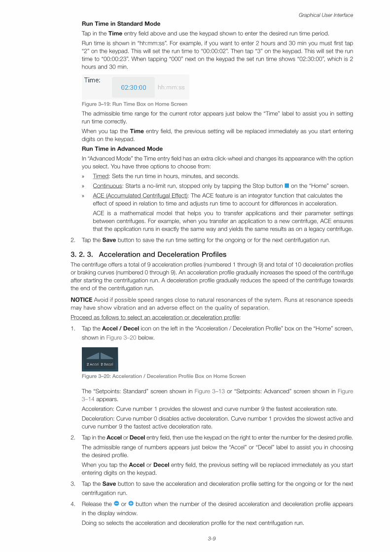
3-9
Graphical User Interface
Run Time in Standard Mode
Tap in the Time entry field above and use the keypad shown to enter the desired run time period.
Run time is shown in “hh:mm:ss”. For example, if you want to enter 2 hours and 30 min you must first tap “2” on the keypad. This will set the run time to “00:00:02”. Then tap “3” on the keypad. This will set the run time to “00:00:23”. When tapping “000” next on the keypad the set run time shows “02:30:00”, which is 2 hours and 30 min.
Figure 3–19: Run Time Box on Home Screen
The admissible time range for the current rotor appears just below the “Time” label to assist you in setting run time correctly.
When you tap the Time entry field, the previous setting will be replaced immediately as you start entering digits on the keypad.
Run Time in Advanced Mode
In “Advanced Mode” the Time entry field has an extra click-wheel and changes its appearance with the option you select. You have three options to choose from:
» Timed: Sets the run time in hours, minutes, and seconds.
» Continuous: Starts a no-limit run, stopped only by tapping the Stop button on the “Home” screen.
» ACE (Accumulated Centrifugal Effect): The ACE feature is an integrator function that calculates the effect of speed in relation to time and adjusts run time to account for differences in acceleration.
ACE is a mathematical model that helps you to transfer applications and their parameter settings between centrifuges. For example, when you transfer an application to a new centrifuge, ACE ensures that the application runs in exactly the same way and yields the same results as on a legacy centrifuge.
2. Tap the Save button to save the run time setting for the ongoing or for the next centrifugation run.
3. 2. 3. Acceleration and Deceleration ProfilesThe centrifuge offers a total of 9 acceleration profiles (numbered 1 through 9) and total of 10 deceleration profiles or braking curves (numbered 0 through 9). An acceleration profile gradually increases the speed of the centrifuge after starting the centrifugation run. A deceleration profile gradually reduces the speed of the centrifuge towards the end of the centrifugation run.
NOTICE Avoid if possible speed ranges close to natural resonances of the sytem. Runs at resonance speeds may have show vibration and an adverse effect on the quality of separation.
Proceed as follows to select an acceleration or deceleration profile:
1. Tap the Accel / Decel icon on the left in the “Acceleration / Deceleration Profile” box on the “Home” screen,
shown in Figure 3–20 below.
Figure 3–20: Acceleration / Deceleration Profile Box on Home Screen
The “Setpoints: Standard” screen shown in Figure 3–13 or “Setpoints: Advanced” screen shown in Figure 3–14 appears.
Acceleration: Curve number 1 provides the slowest and curve number 9 the fastest acceleration rate.
Deceleration: Curve number 0 disables active deceleration. Curve number 1 provides the slowest active and curve number 9 the fastest active deceleration rate.
2. Tap in the Accel or Decel entry field, then use the keypad on the right to enter the number for the desired profile.
The admissible range of numbers appears just below the “Accel” or “Decel” label to assist you in choosing the desired profile.
When you tap the Accel or Decel entry field, the previous setting will be replaced immediately as you start entering digits on the keypad.
3. Tap the Save button to save the acceleration and deceleration profile setting for the ongoing or for the next
centrifugation run.
4. Release the or button when the number of the desired acceleration and deceleration profile appears
in the display window.
Doing so selects the acceleration and deceleration profile for the next centrifugation run.
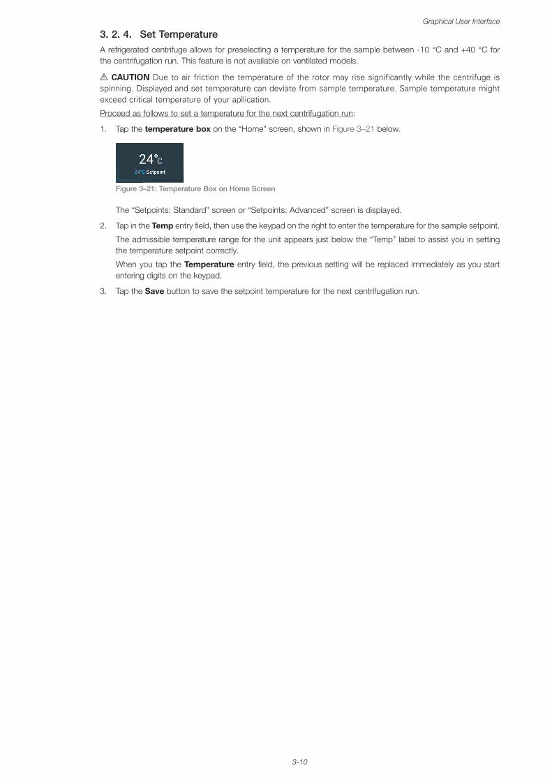
3-10
Graphical User Interface
3. 2. 4. Set TemperatureA refrigerated centrifuge allows for preselecting a temperature for the sample between -10 °C and +40 °C for the centrifugation run. This feature is not available on ventilated models.
A CAUTION Due to air friction the temperature of the rotor may rise significantly while the centrifuge is spinning. Displayed and set temperature can deviate from sample temperature. Sample temperature might exceed critical temperature of your apllication.
Proceed as follows to set a temperature for the next centrifugation run:
1. Tap the temperature box on the “Home” screen, shown in Figure 3–21 below.
Figure 3–21: Temperature Box on Home Screen
The “Setpoints: Standard” screen or “Setpoints: Advanced” screen is displayed.
2. Tap in the Temp entry field, then use the keypad on the right to enter the temperature for the sample setpoint.
The admissible temperature range for the unit appears just below the “Temp” label to assist you in setting the temperature setpoint correctly.
When you tap the Temperature entry field, the previous setting will be replaced immediately as you start entering digits on the keypad.
3. Tap the Save button to save the setpoint temperature for the next centrifugation run.
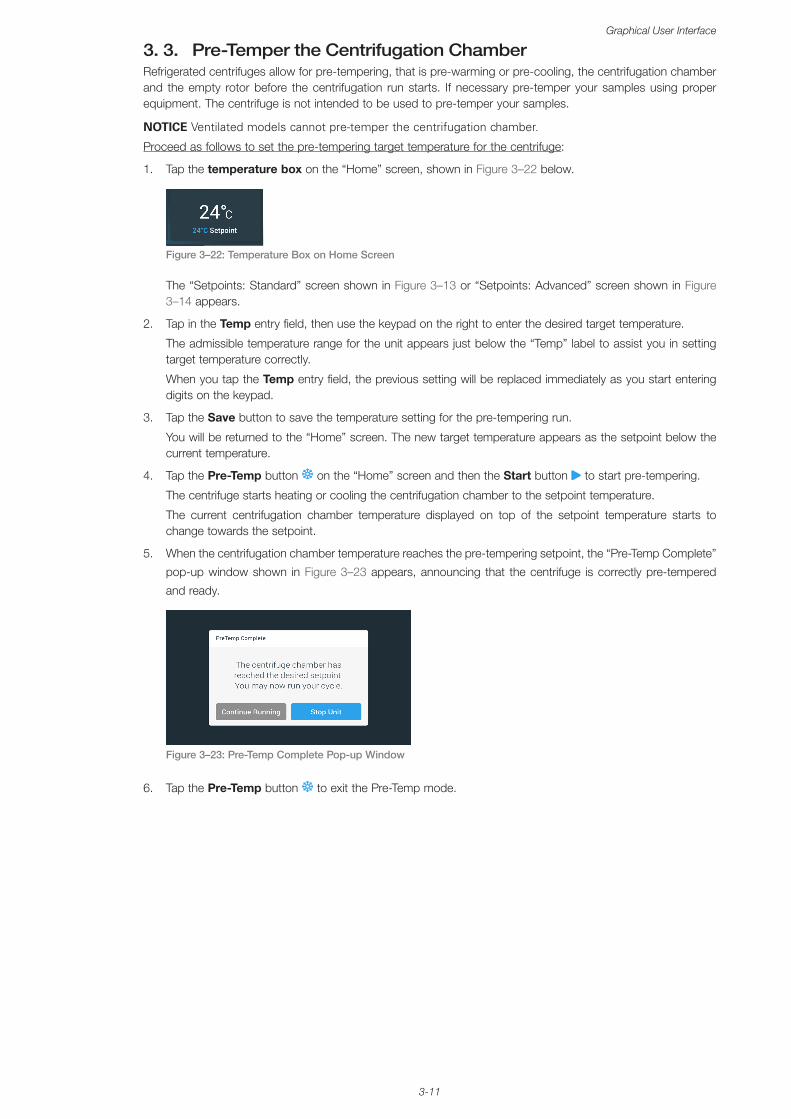
3-11
Graphical User Interface
3. 3. Pre-Temper the Centrifugation ChamberRefrigerated centrifuges allow for pre-tempering, that is pre-warming or pre-cooling, the centrifugation chamber and the empty rotor before the centrifugation run starts. If necessary pre-temper your samples using proper equipment. The centrifuge is not intended to be used to pre-temper your samples.
NOTICE Ventilated models cannot pre-temper the centrifugation chamber.
Proceed as follows to set the pre-tempering target temperature for the centrifuge:
1. Tap the temperature box on the “Home” screen, shown in Figure 3–22 below.
Figure 3–22: Temperature Box on Home Screen
The “Setpoints: Standard” screen shown in Figure 3–13 or “Setpoints: Advanced” screen shown in Figure 3–14 appears.
2. Tap in the Temp entry field, then use the keypad on the right to enter the desired target temperature.
The admissible temperature range for the unit appears just below the “Temp” label to assist you in setting target temperature correctly.
When you tap the Temp entry field, the previous setting will be replaced immediately as you start entering digits on the keypad.
3. Tap the Save button to save the temperature setting for the pre-tempering run.
You will be returned to the “Home” screen. The new target temperature appears as the setpoint below the current temperature.
4. Tap the Pre-Temp button on the “Home” screen and then the Start button to start pre-tempering.
The centrifuge starts heating or cooling the centrifugation chamber to the setpoint temperature.
The current centrifugation chamber temperature displayed on top of the setpoint temperature starts to change towards the setpoint.
5. When the centrifugation chamber temperature reaches the pre-tempering setpoint, the “Pre-Temp Complete”
pop-up window shown in Figure 3–23 appears, announcing that the centrifuge is correctly pre-tempered
and ready.
Figure 3–23: Pre-Temp Complete Pop-up Window
6. Tap the Pre-Temp button to exit the Pre-Temp mode.
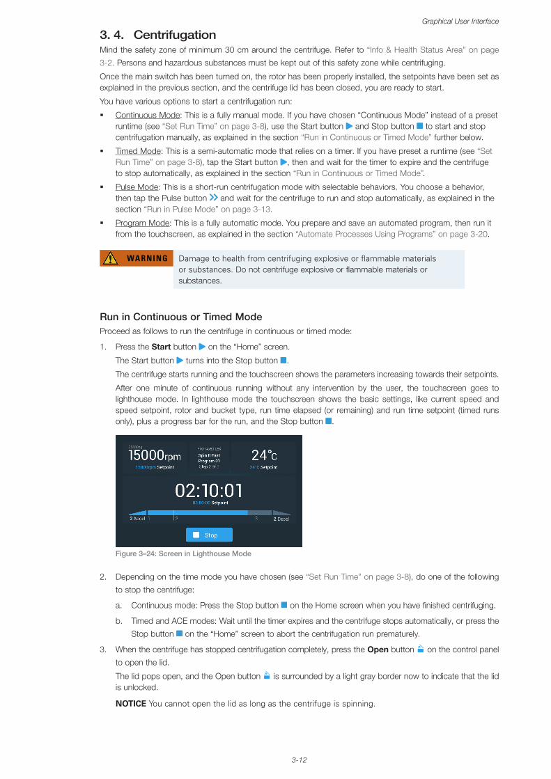
3-12
Graphical User Interface
3. 4. CentrifugationMind the safety zone of minimum 30 cm around the centrifuge. Refer to “Info & Health Status Area” on page
3-2. Persons and hazardous substances must be kept out of this safety zone while centrifuging.
Once the main switch has been turned on, the rotor has been properly installed, the setpoints have been set as explained in the previous section, and the centrifuge lid has been closed, you are ready to start.
You have various options to start a centrifugation run:
� Continuous Mode: This is a fully manual mode. If you have chosen “Continuous Mode” instead of a preset runtime (see “Set Run Time” on page 3-8), use the Start button and Stop button to start and stop centrifugation manually, as explained in the section “Run in Continuous or Timed Mode” further below.
� Timed Mode: This is a semi-automatic mode that relies on a timer. If you have preset a runtime (see “Set Run Time” on page 3-8), tap the Start button , then and wait for the timer to expire and the centrifuge to stop automatically, as explained in the section “Run in Continuous or Timed Mode”.
� Pulse Mode: This is a short-run centrifugation mode with selectable behaviors. You choose a behavior, then tap the Pulse button and wait for the centrifuge to run and stop automatically, as explained in the section “Run in Pulse Mode” on page 3-13.
� Program Mode: This is a fully automatic mode. You prepare and save an automated program, then run it from the touchscreen, as explained in the section “Automate Processes Using Programs” on page 3-20.
WARNING Damage to health from centrifuging explosive or flammable materials or substances. Do not centrifuge explosive or flammable materials or substances.
Run in Continuous or Timed ModeProceed as follows to run the centrifuge in continuous or timed mode:
1. Press the Start button on the “Home” screen.
The Start button turns into the Stop button .
The centrifuge starts running and the touchscreen shows the parameters increasing towards their setpoints.
After one minute of continuous running without any intervention by the user, the touchscreen goes to lighthouse mode. In lighthouse mode the touchscreen shows the basic settings, like current speed and speed setpoint, rotor and bucket type, run time elapsed (or remaining) and run time setpoint (timed runs only), plus a progress bar for the run, and the Stop button .
Figure 3–24: Screen in Lighthouse Mode
2. Depending on the time mode you have chosen (see “Set Run Time” on page 3-8), do one of the following
to stop the centrifuge:
a. Continuous mode: Press the Stop button on the Home screen when you have finished centrifuging.
b. Timed and ACE modes: Wait until the timer expires and the centrifuge stops automatically, or press the
Stop button on the “Home” screen to abort the centrifugation run prematurely.
3. When the centrifuge has stopped centrifugation completely, press the Open button on the control panel
to open the lid.
The lid pops open, and the Open button is surrounded by a light gray border now to indicate that the lid is unlocked.
NOTICE You cannot open the lid as long as the centrifuge is spinning.
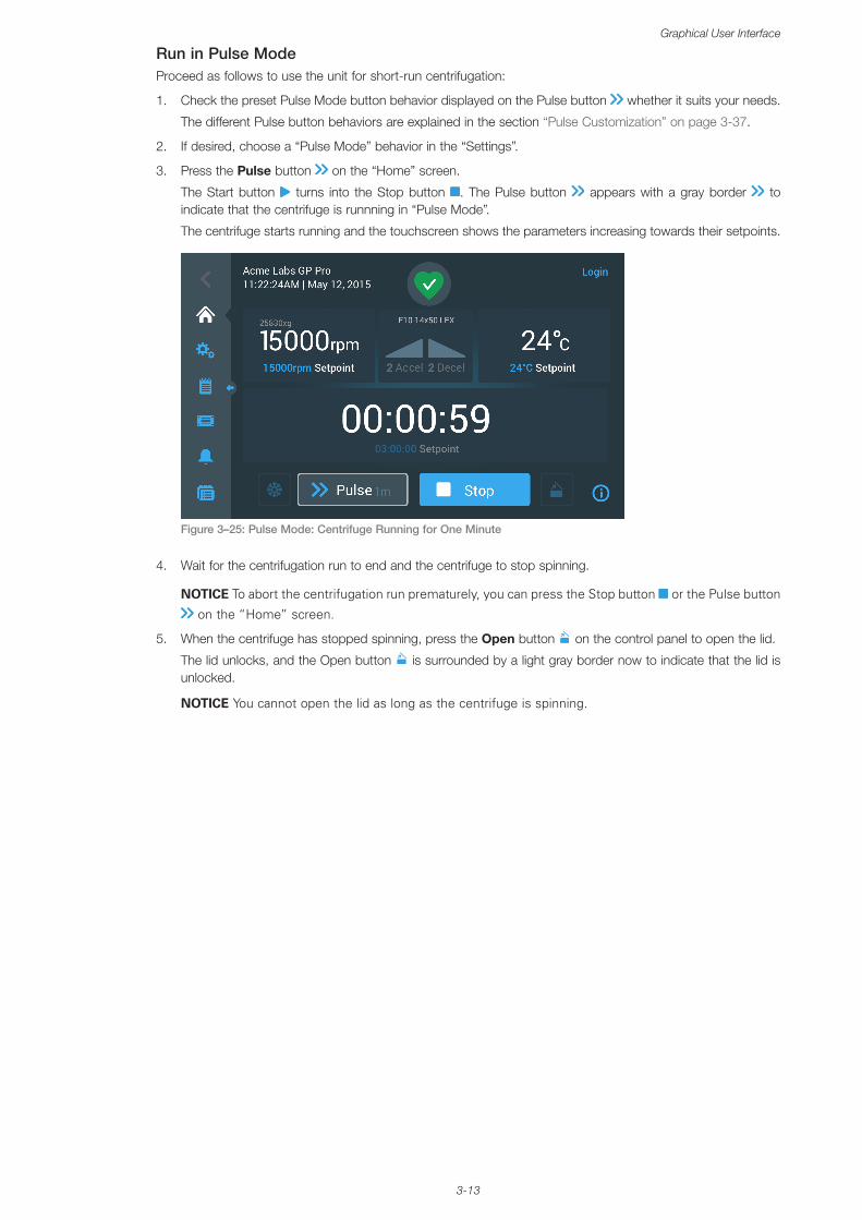
3-13
Graphical User Interface
Run in Pulse ModeProceed as follows to use the unit for short-run centrifugation:
1. Check the preset Pulse Mode button behavior displayed on the Pulse button whether it suits your needs.
The different Pulse button behaviors are explained in the section “Pulse Customization” on page 3-37.
2. If desired, choose a “Pulse Mode” behavior in the “Settings”.
3. Press the Pulse button on the “Home” screen.
The Start button turns into the Stop button . The Pulse button appears with a gray border to indicate that the centrifuge is runnning in “Pulse Mode”.
The centrifuge starts running and the touchscreen shows the parameters increasing towards their setpoints.
Figure 3–25: Pulse Mode: Centrifuge Running for One Minute
4. Wait for the centrifugation run to end and the centrifuge to stop spinning.
NOTICE To abort the centrifugation run prematurely, you can press the Stop button or the Pulse button
on the “Home” screen.
5. When the centrifuge has stopped spinning, press the Open button on the control panel to open the lid.
The lid unlocks, and the Open button is surrounded by a light gray border now to indicate that the lid is unlocked.
NOTICE You cannot open the lid as long as the centrifuge is spinning.
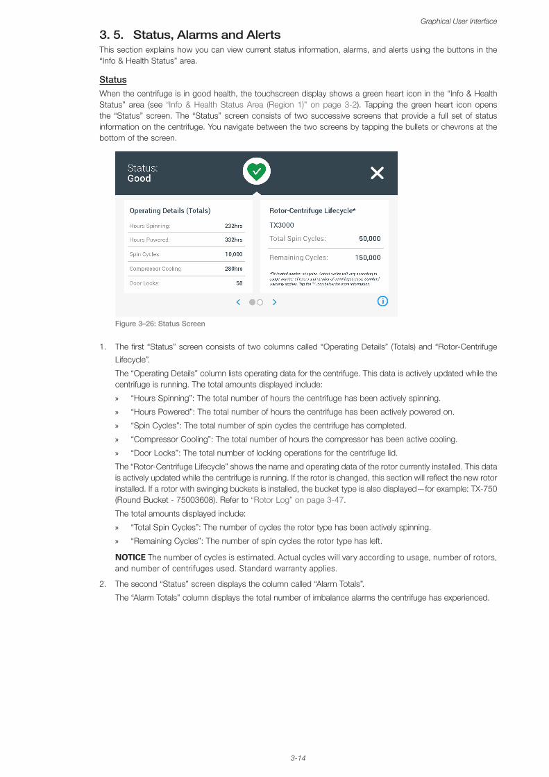
3-14
Graphical User Interface
3. 5. Status, Alarms and AlertsThis section explains how you can view current status information, alarms, and alerts using the buttons in the “Info & Health Status” area.
StatusWhen the centrifuge is in good health, the touchscreen display shows a green heart icon in the “Info & Health Status” area (see “Info & Health Status Area (Region 1)” on page 3-2). Tapping the green heart icon opens the “Status” screen. The “Status” screen consists of two successive screens that provide a full set of status information on the centrifuge. You navigate between the two screens by tapping the bullets or chevrons at the bottom of the screen.
Figure 3–26: Status Screen
1. The first “Status” screen consists of two columns called “Operating Details” (Totals) and “Rotor-Centrifuge
Lifecycle”.
The “Operating Details” column lists operating data for the centrifuge. This data is actively updated while the centrifuge is running. The total amounts displayed include:
» “Hours Spinning”: The total number of hours the centrifuge has been actively spinning.
» “Hours Powered”: The total number of hours the centrifuge has been actively powered on.
» “Spin Cycles”: The total number of spin cycles the centrifuge has completed.
» “Compressor Cooling”: The total number of hours the compressor has been active cooling.
» “Door Locks”: The total number of locking operations for the centrifuge lid.
The “Rotor-Centrifuge Lifecycle” shows the name and operating data of the rotor currently installed. This data is actively updated while the centrifuge is running. If the rotor is changed, this section will reflect the new rotor installed. If a rotor with swinging buckets is installed, the bucket type is also displayed—for example: TX-750 (Round Bucket - 75003608). Refer to “Rotor Log” on page 3-47.
The total amounts displayed include:
» “Total Spin Cycles”: The number of cycles the rotor type has been actively spinning.
» “Remaining Cycles”: The number of spin cycles the rotor type has left.
NOTICE The number of cycles is estimated. Actual cycles will vary according to usage, number of rotors, and number of centrifuges used. Standard warranty applies.
2. The second “Status” screen displays the column called “Alarm Totals”.
The “Alarm Totals” column displays the total number of imbalance alarms the centrifuge has experienced.
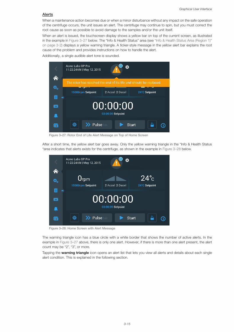
3-15
Graphical User Interface
AlertsWhen a maintenance action becomes due or when a minor disturbance without any impact on the safe operation of the centrifuge occurs, the unit issues an alert. The centrifuge may continue to spin, but you must correct the root cause as soon as possible to avoid damage to the samples and/or the unit itself.
When an alert is issued, the touchscreen display shows a yellow bar on top of the current screen, as illustrated in the example in Figure 3–27 below. The “Info & Health Status” area (see “Info & Health Status Area (Region 1)” on page 3-2) displays a yellow warning triangle. A ticker-style message in the yellow alert bar explains the root cause of the problem and provides instructions on how to handle the alert.
Additionally, a single audible alert tone is sounded.
Figure 3–27: Rotor End of Life Alert Message on Top of Home Screen
After a short time, the yellow alert bar goes away. Only the yellow warning triangle in the “Info & Health Status “area indicates that alerts exists for the centrifuge, as shown in the example in Figure 3–28 below.
Figure 3–28: Home Screen with Alert Message
The warning triangle icon has a blue circle with a white border that shows the number of active alerts. In the example in Figure 3–27 above, there is only one alert. However, if there is more than one alert present, the alert count may be “2”, “3”, or more.
Tapping the warning triangle icon opens an alert list that lets you view all alerts and details about each single alert condition. This is explained in the following section.
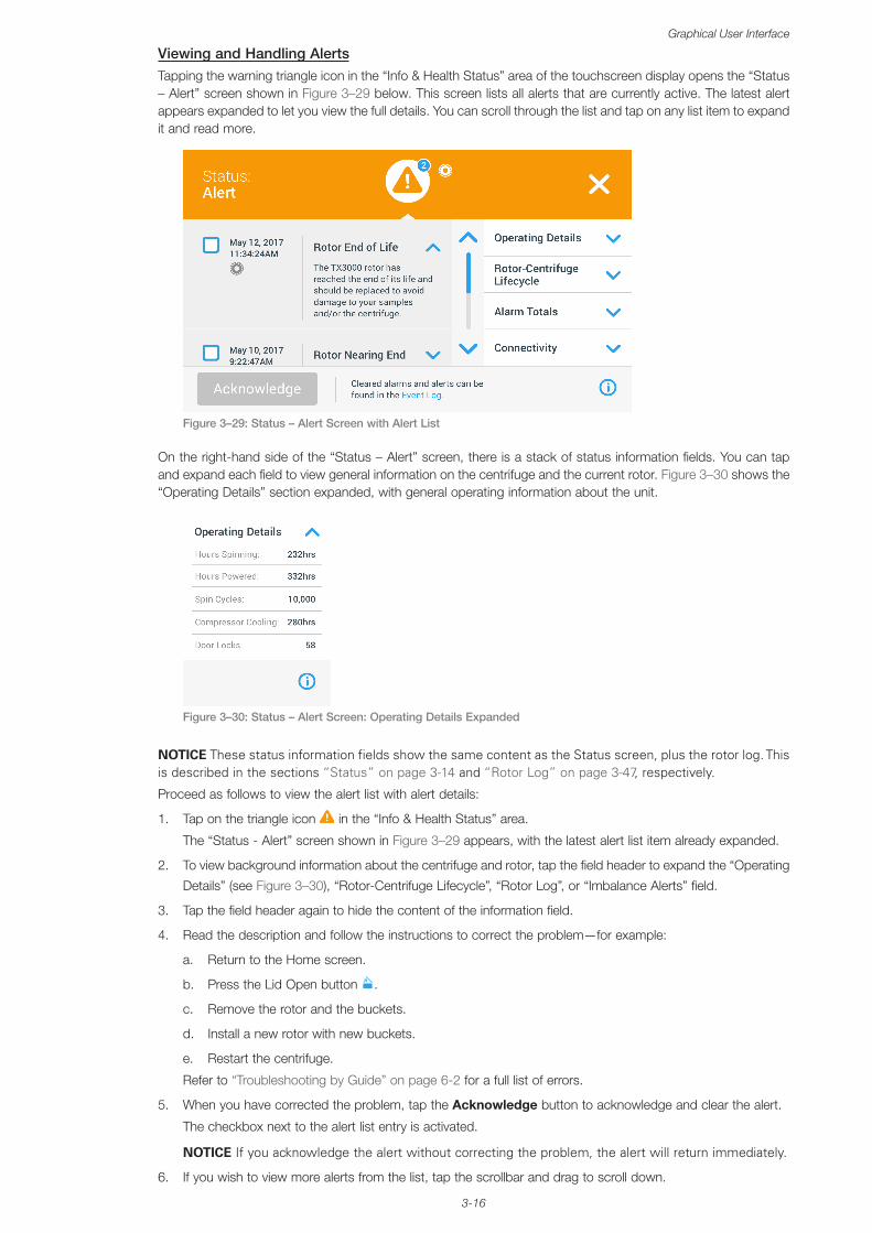
3-16
Graphical User Interface
Viewing and Handling AlertsTapping the warning triangle icon in the “Info & Health Status” area of the touchscreen display opens the “Status – Alert” screen shown in Figure 3–29 below. This screen lists all alerts that are currently active. The latest alert appears expanded to let you view the full details. You can scroll through the list and tap on any list item to expand it and read more.
Figure 3–29: Status – Alert Screen with Alert List
On the right-hand side of the “Status – Alert” screen, there is a stack of status information fields. You can tap and expand each field to view general information on the centrifuge and the current rotor. Figure 3–30 shows the “Operating Details” section expanded, with general operating information about the unit.
Figure 3–30: Status – Alert Screen: Operating Details Expanded
NOTICE These status information fields show the same content as the Status screen, plus the rotor log. This is described in the sections “Status” on page 3-14 and “Rotor Log” on page 3-47, respectively.
Proceed as follows to view the alert list with alert details:
1. Tap on the triangle icon in the “Info & Health Status” area.
The “Status - Alert” screen shown in Figure 3–29 appears, with the latest alert list item already expanded.
2. To view background information about the centrifuge and rotor, tap the field header to expand the “Operating
Details” (see Figure 3–30), “Rotor-Centrifuge Lifecycle”, “Rotor Log”, or “Imbalance Alerts” field.
3. Tap the field header again to hide the content of the information field.
4. Read the description and follow the instructions to correct the problem—for example:
a. Return to the Home screen.
b. Press the Lid Open button .
c. Remove the rotor and the buckets.
d. Install a new rotor with new buckets.
e. Restart the centrifuge.
Refer to “Troubleshooting by Guide” on page 6-2 for a full list of errors.
5. When you have corrected the problem, tap the Acknowledge button to acknowledge and clear the alert.
The checkbox next to the alert list entry is activated.
NOTICE If you acknowledge the alert without correcting the problem, the alert will return immediately.
6. If you wish to view more alerts from the list, tap the scrollbar and drag to scroll down.
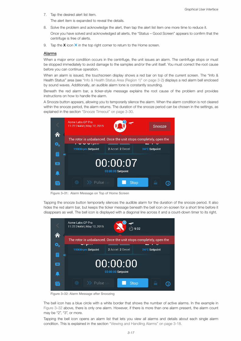
3-17
Graphical User Interface
7. Tap the desired alert list item.
The alert item is expanded to reveal the details.
8. Solve the problem and acknowledge the alert, then tap the alert list item one more time to reduce it.
Once you have solved and acknowledged all alerts, the “Status – Good Screen” appears to confirm that the centrifuge is free of alerts.
9. Tap the X icon in the top right corner to return to the Home screen.
AlarmsWhen a major error condition occurs in the centrifuge, the unit issues an alarm. The centrifuge stops or must be stopped immediately to avoid damage to the samples and/or the unit itself. You must correct the root cause before you can continue operation.
When an alarm is issued, the touchscreen display shows a red bar on top of the current screen. The “Info & Health Status” area (see “Info & Health Status Area (Region 1)” on page 3-2) displays a red alarm bell enclosed by sound waves. Additionally, an audible alarm tone is constantly sounding.
Beneath the red alarm bar, a ticker-style message explains the root cause of the problem and provides instructions on how to handle the alarm.
A Snooze button appears, allowing you to temporarily silence the alarm. When the alarm condition is not cleared within the snooze period, the alarm returns. The duration of the snooze period can be chosen in the settings, as explained in the section “Snooze Timeout” on page 3-30.
Figure 3–31: Alarm Message on Top of Home Screen
Tapping the snooze button temporarily silences the audible alarm for the duration of the snooze period. It also hides the red alarm bar, but keeps the ticker message beneath the bell icon on-screen for a short time before it disappears as well. The bell icon is displayed with a diagonal line across it and a count-down timer to its right.
Figure 3–32: Alarm Message after Snoozing
The bell icon has a blue circle with a white border that shows the number of active alarms. In the example in Figure 3–32 above, there is only one alarm. However, if there is more than one alarm present, the alarm count may be “2”, “3”, or more.
Tapping the bell icon opens an alarm list that lets you view all alarms and details about each single alarm condition. This is explained in the section “Viewing and Handling Alarms” on page 3-18.
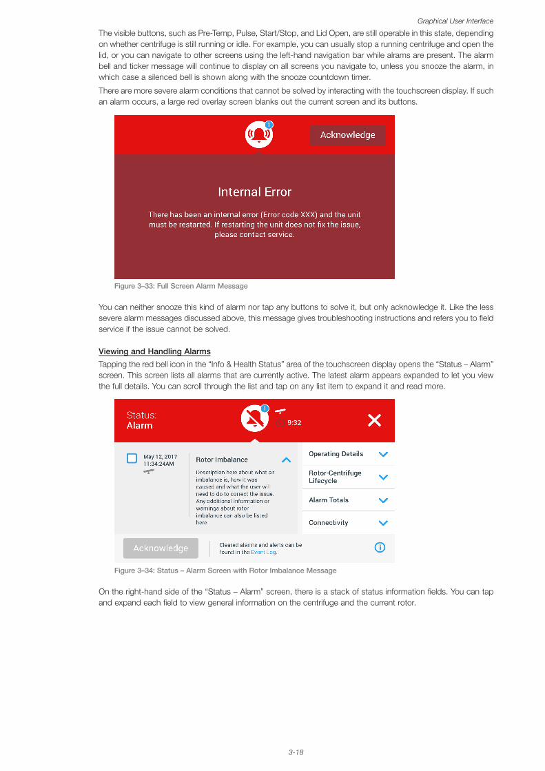
3-18
Graphical User Interface
The visible buttons, such as Pre-Temp, Pulse, Start/Stop, and Lid Open, are still operable in this state, depending on whether centrifuge is still running or idle. For example, you can usually stop a running centrifuge and open the lid, or you can navigate to other screens using the left-hand navigation bar while alrams are present. The alarm bell and ticker message will continue to display on all screens you navigate to, unless you snooze the alarm, in which case a silenced bell is shown along with the snooze countdown timer.
There are more severe alarm conditions that cannot be solved by interacting with the touchscreen display. If such an alarm occurs, a large red overlay screen blanks out the current screen and its buttons.
Figure 3–33: Full Screen Alarm Message
You can neither snooze this kind of alarm nor tap any buttons to solve it, but only acknowledge it. Like the less severe alarm messages discussed above, this message gives troubleshooting instructions and refers you to field service if the issue cannot be solved.
Viewing and Handling Alarms
Tapping the red bell icon in the “Info & Health Status” area of the touchscreen display opens the “Status – Alarm” screen. This screen lists all alarms that are currently active. The latest alarm appears expanded to let you view the full details. You can scroll through the list and tap on any list item to expand it and read more.
Figure 3–34: Status – Alarm Screen with Rotor Imbalance Message
On the right-hand side of the “Status – Alarm” screen, there is a stack of status information fields. You can tap and expand each field to view general information on the centrifuge and the current rotor.
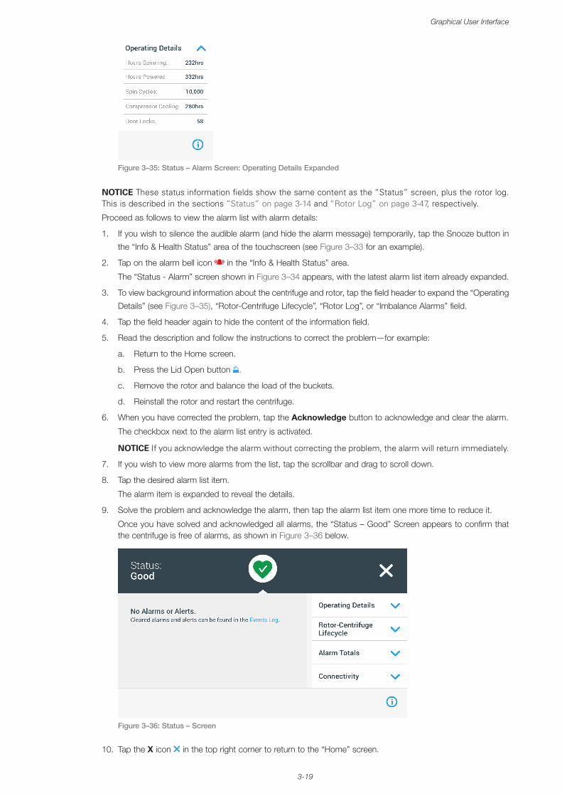
3-19
Graphical User Interface
Figure 3–35: Status – Alarm Screen: Operating Details Expanded
NOTICE These status information fields show the same content as the “Status” screen, plus the rotor log. This is described in the sections “Status” on page 3-14 and “Rotor Log” on page 3-47, respectively.
Proceed as follows to view the alarm list with alarm details:
1. If you wish to silence the audible alarm (and hide the alarm message) temporarily, tap the Snooze button in
the “Info & Health Status” area of the touchscreen (see Figure 3–33 for an example).
2. Tap on the alarm bell icon in the “Info & Health Status” area.
The “Status - Alarm” screen shown in Figure 3–34 appears, with the latest alarm list item already expanded.
3. To view background information about the centrifuge and rotor, tap the field header to expand the “Operating
Details” (see Figure 3–35), “Rotor-Centrifuge Lifecycle”, “Rotor Log”, or “Imbalance Alarms” field.
4. Tap the field header again to hide the content of the information field.
5. Read the description and follow the instructions to correct the problem—for example:
a. Return to the Home screen.
b. Press the Lid Open button .
c. Remove the rotor and balance the load of the buckets.
d. Reinstall the rotor and restart the centrifuge.
6. When you have corrected the problem, tap the Acknowledge button to acknowledge and clear the alarm.
The checkbox next to the alarm list entry is activated.
NOTICE If you acknowledge the alarm without correcting the problem, the alarm will return immediately.
7. If you wish to view more alarms from the list, tap the scrollbar and drag to scroll down.
8. Tap the desired alarm list item.
The alarm item is expanded to reveal the details.
9. Solve the problem and acknowledge the alarm, then tap the alarm list item one more time to reduce it.
Once you have solved and acknowledged all alarms, the “Status – Good” Screen appears to confirm that the centrifuge is free of alarms, as shown in Figure 3–36 below.
Figure 3–36: Status – Screen
10. Tap the X icon in the top right corner to return to the “Home” screen.
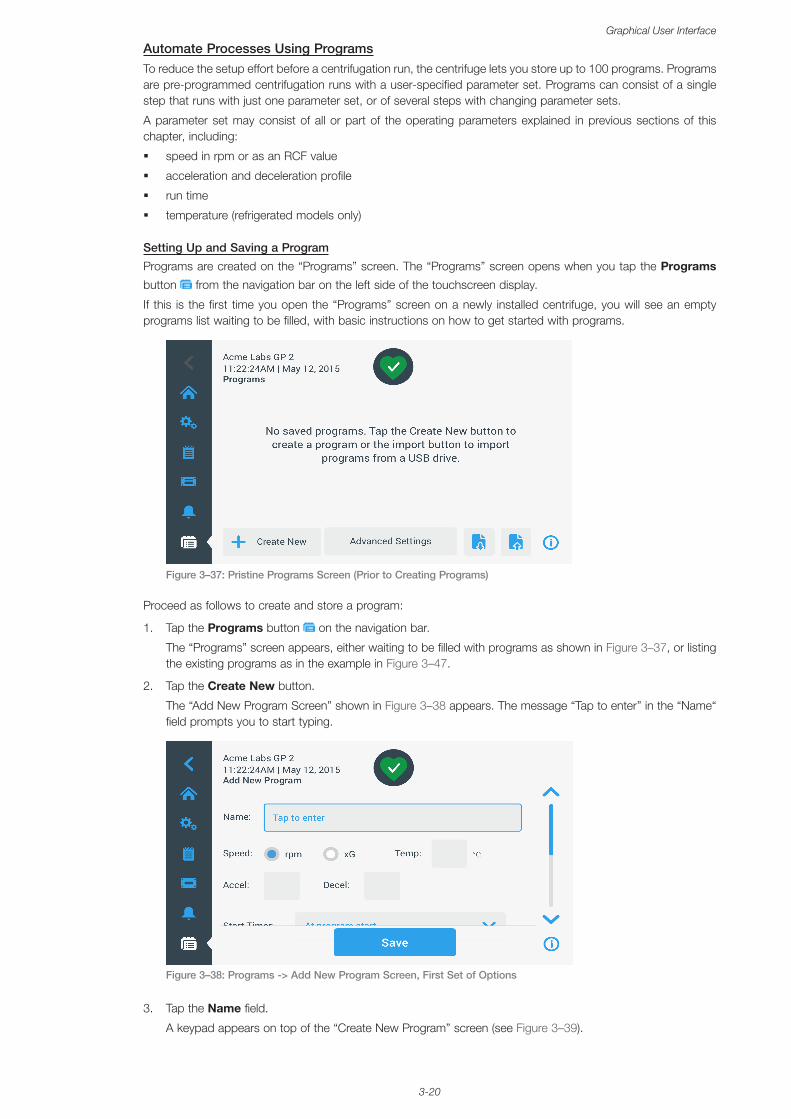
3-20
Graphical User Interface
Automate Processes Using ProgramsTo reduce the setup effort before a centrifugation run, the centrifuge lets you store up to 100 programs. Programs are pre-programmed centrifugation runs with a user-specified parameter set. Programs can consist of a single step that runs with just one parameter set, or of several steps with changing parameter sets.
A parameter set may consist of all or part of the operating parameters explained in previous sections of this chapter, including:
� speed in rpm or as an RCF value
� acceleration and deceleration profile
� run time
� temperature (refrigerated models only)
Setting Up and Saving a Program
Programs are created on the “Programs” screen. The “Programs” screen opens when you tap the Programs
button from the navigation bar on the left side of the touchscreen display.
If this is the first time you open the “Programs” screen on a newly installed centrifuge, you will see an empty programs list waiting to be filled, with basic instructions on how to get started with programs.
Figure 3–37: Pristine Programs Screen (Prior to Creating Programs)
Proceed as follows to create and store a program:
1. Tap the Programs button on the navigation bar.
The “Programs” screen appears, either waiting to be filled with programs as shown in Figure 3–37, or listing the existing programs as in the example in Figure 3–47.
2. Tap the Create New button.
The “Add New Program Screen” shown in Figure 3–38 appears. The message “Tap to enter” in the “Name“ field prompts you to start typing.
Figure 3–38: Programs -> Add New Program Screen, First Set of Options
3. Tap the Name field.
A keypad appears on top of the “Create New Program” screen (see Figure 3–39).
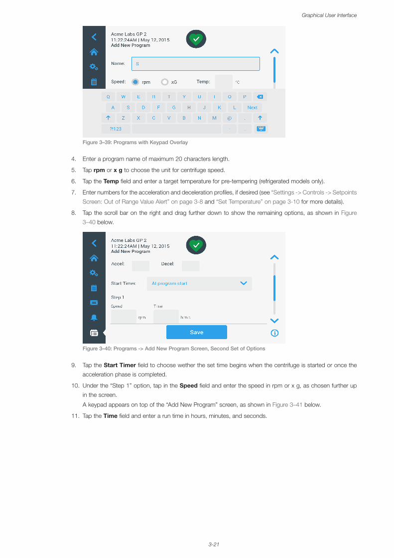
3-21
Graphical User Interface
Figure 3–39: Programs with Keypad Overlay
4. Enter a program name of maximum 20 characters length.
5. Tap rpm or x g to choose the unit for centrifuge speed.
6. Tap the Temp field and enter a target temperature for pre-tempering (refrigerated models only).
7. Enter numbers for the acceleration and deceleration profiles, if desired (see “Settings -> Controls -> Setpoints
Screen: Out of Range Value Alert” on page 3-8 and “Set Temperature” on page 3-10 for more details).
8. Tap the scroll bar on the right and drag further down to show the remaining options, as shown in Figure
3–40 below.
Figure 3–40: Programs -> Add New Program Screen, Second Set of Options
9. Tap the Start Timer field to choose wether the set time begins when the centrifuge is started or once the
acceleration phase is completed.
10. Under the “Step 1” option, tap in the Speed field and enter the speed in rpm or x g, as chosen further up
in the screen.
A keypad appears on top of the “Add New Program” screen, as shown in Figure 3–41 below.
11. Tap the Time field and enter a run time in hours, minutes, and seconds.
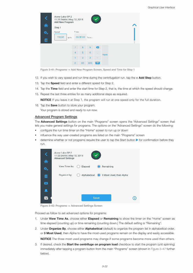
3-22
Graphical User Interface
Figure 3–41: Programs -> Add New Program Screen, Speed and Time for Step 1
12. If you wish to vary speed and run time during the centrifugation run, tap the + Add Step button.
13. Tap the Speed field and enter a different speed for Step 2.
14. Tap the Time field and enter the start time for Step 2, that is, the time at which the speed should change.
15. Repeat the last three entries for as many additional steps as required.
NOTICE If you leave it at Step 1, the program will run at one speed only for the full duration.
16. Tap the Save button to store your program.
Your program is stored and ready to run now.
Advanced Program SettingsThe Advanced Settings button on the main “Programs” screen opens the “Advanced Settings” screen that lets you make general settings for programs. The options on the “Advanced Settings” screen do the following:
� configure the run time timer on the “Home” screen to run up or down
� influence the way user-created programs are listed on the main “Programs” screen
� determine whether or not programs require the user to tap the Start button for confirmation before they run.
Figure 3–42: Programs -> Advanced Settings Screen
Proceed as follow to set advanced options for programs:
1. Under View Time As, choose either Elapsed or Remaining to show the timer on the “Home” screen as
time elapsed (counting up) or time remaining (counting down.) The default setting is “Remaining”.
2. Under Organize By, choose either Alphabetical (default) to organize the program list in alphabetical order,
or 3 Most Used, then Alpha to have the most-used programs remain on the display and easily accessible.
NOTICE The three most used programs may change if some programs become more used than others.
3. If desired, check the Start the centrifuge on program load checkbox to start the program (unit spinning)
immediately after tapping a program button from the main “Programs” screen (shown in Figure 3–47 further
below).
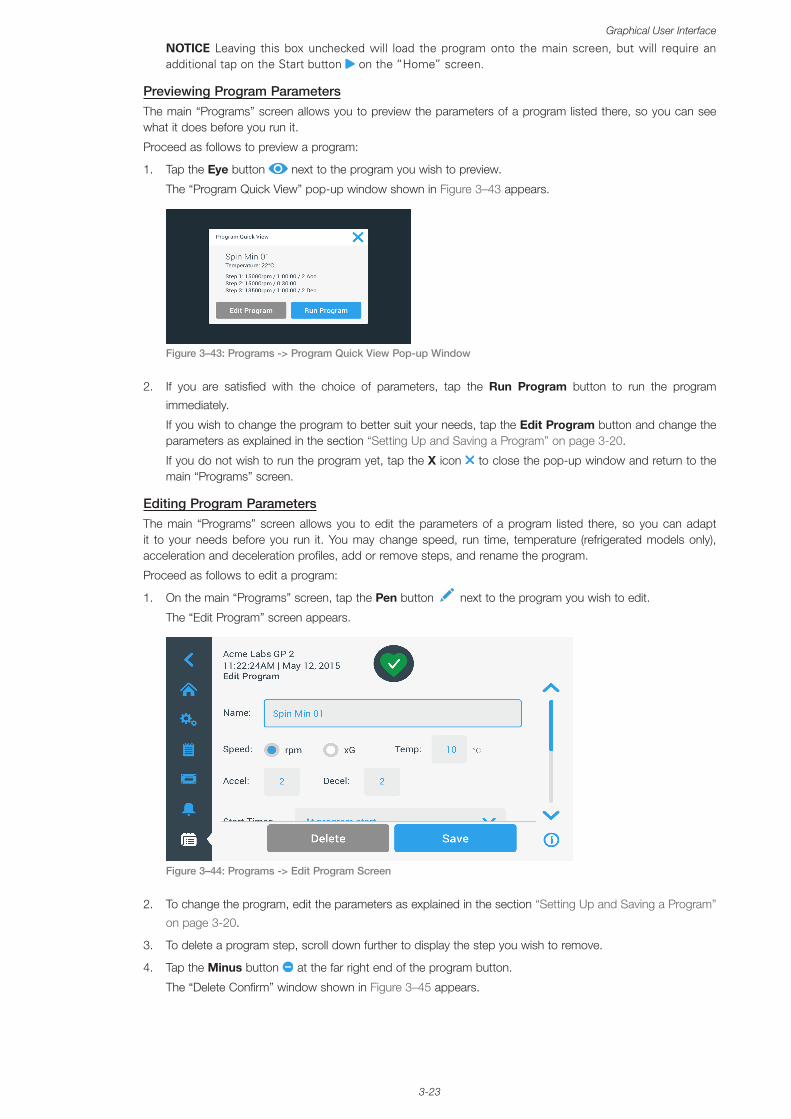
3-23
Graphical User Interface
NOTICE Leaving this box unchecked will load the program onto the main screen, but will require an additional tap on the Start button on the “Home” screen.
Previewing Program ParametersThe main “Programs” screen allows you to preview the parameters of a program listed there, so you can see what it does before you run it.
Proceed as follows to preview a program:
1. Tap the Eye button next to the program you wish to preview.
The “Program Quick View” pop-up window shown in Figure 3–43 appears.
Figure 3–43: Programs -> Program Quick View Pop-up Window
2. If you are satisfied with the choice of parameters, tap the Run Program button to run the program
immediately.
If you wish to change the program to better suit your needs, tap the Edit Program button and change the parameters as explained in the section “Setting Up and Saving a Program” on page 3-20.
If you do not wish to run the program yet, tap the X icon to close the pop-up window and return to the main “Programs” screen.
Editing Program ParametersThe main “Programs” screen allows you to edit the parameters of a program listed there, so you can adapt it to your needs before you run it. You may change speed, run time, temperature (refrigerated models only), acceleration and deceleration profiles, add or remove steps, and rename the program.
Proceed as follows to edit a program:
1. On the main “Programs” screen, tap the Pen button next to the program you wish to edit.
The “Edit Program” screen appears.
Figure 3–44: Programs -> Edit Program Screen
2. To change the program, edit the parameters as explained in the section “Setting Up and Saving a Program”
on page 3-20.
3. To delete a program step, scroll down further to display the step you wish to remove.
4. Tap the Minus button at the far right end of the program button.
The “Delete Confirm” window shown in Figure 3–45 appears.
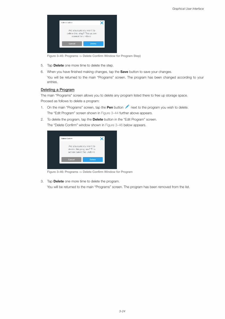
3-24
Graphical User Interface
Figure 3–45: Programs -> Delete Confirm Window for Program Step)
5. Tap Delete one more time to delete the step.
6. When you have finished making changes, tap the Save button to save your changes.
You will be returned to the main “Programs” screen. The program has been changed according to your entries.
Deleting a ProgramThe main “Programs” screen allows you to delete any program listed there to free up storage space.
Proceed as follows to delete a program:
1. On the main “Programs” screen, tap the Pen button next to the program you wish to delete.
The “Edit Program” screen shown in Figure 3–44 further above appears.
2. To delete the program, tap the Delete button in the “Edit Program” screen.
The “Delete Confirm” window shown in Figure 3–46 below appears.
Figure 3–46: Programs -> Delete Confirm Window for Program
3. Tap Delete one more time to delete the program.
You will be returned to the main “Programs” screen. The program has been removed from the list.
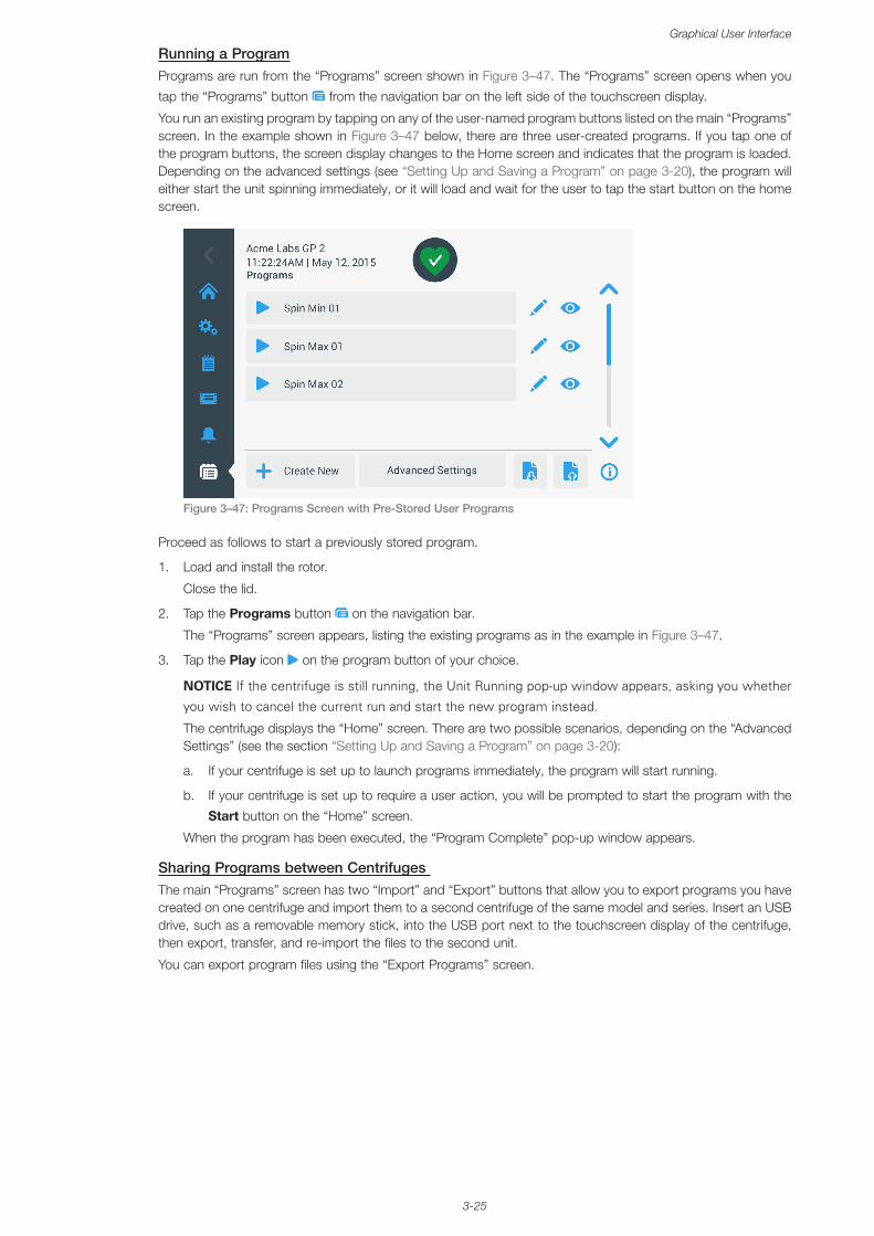
3-25
Graphical User Interface
Running a ProgramPrograms are run from the “Programs” screen shown in Figure 3–47. The “Programs” screen opens when you
tap the “Programs” button from the navigation bar on the left side of the touchscreen display.
You run an existing program by tapping on any of the user-named program buttons listed on the main “Programs” screen. In the example shown in Figure 3–47 below, there are three user-created programs. If you tap one of the program buttons, the screen display changes to the Home screen and indicates that the program is loaded. Depending on the advanced settings (see “Setting Up and Saving a Program” on page 3-20), the program will either start the unit spinning immediately, or it will load and wait for the user to tap the start button on the home screen.
Figure 3–47: Programs Screen with Pre-Stored User Programs
Proceed as follows to start a previously stored program.
1. Load and install the rotor.
Close the lid.
2. Tap the Programs button on the navigation bar.
The “Programs” screen appears, listing the existing programs as in the example in Figure 3–47.
3. Tap the Play icon on the program button of your choice.
NOTICE If the centrifuge is still running, the Unit Running pop-up window appears, asking you whether
you wish to cancel the current run and start the new program instead.
The centrifuge displays the “Home” screen. There are two possible scenarios, depending on the “Advanced Settings” (see the section “Setting Up and Saving a Program” on page 3-20):
a. If your centrifuge is set up to launch programs immediately, the program will start running.
b. If your centrifuge is set up to require a user action, you will be prompted to start the program with the
Start button on the “Home” screen.
When the program has been executed, the “Program Complete” pop-up window appears.
Sharing Programs between Centrifuges The main “Programs” screen has two “Import” and “Export” buttons that allow you to export programs you have created on one centrifuge and import them to a second centrifuge of the same model and series. Insert an USB drive, such as a removable memory stick, into the USB port next to the touchscreen display of the centrifuge, then export, transfer, and re-import the files to the second unit.
You can export program files using the “Export Programs” screen.
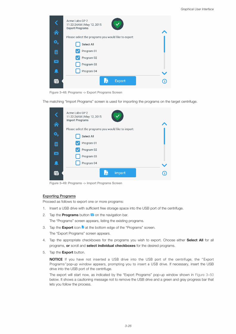
3-26
Graphical User Interface
Figure 3–48: Programs -> Export Programs Screen
The matching “Import Programs” screen is used for importing the programs on the target centrifuge.
Figure 3–49: Programs -> Import Programs Screen
Exporting Programs
Proceed as follows to export one or more programs:
1. Insert a USB drive with sufficient free storage space into the USB port of the centrifuge.
2. Tap the Programs button on the navigation bar.
The “Programs” screen appears, listing the existing programs.
3. Tap the Export icon at the bottom edge of the “Programs” screen.
The “Export Programs” screen appears.
4. Tap the appropriate checkboxes for the programs you wish to export. Choose either Select All for all
programs, or scroll and select individual checkboxes for the desired programs.
5. Tap the Export button.
NOTICE If you have not inserted a USB drive into the USB port of the centrifuge, the “Export Programs“pop-up window appears, prompting you to insert a USB drive. If necessary, insert the USB drive into the USB port of the centrifuge.
The export will start now, as indicated by the “Export Programs” pop-up window shown in Figure 3–50 below. It shows a cautioning message not to remove the USB drive and a green and gray progress bar that lets you follow the process.
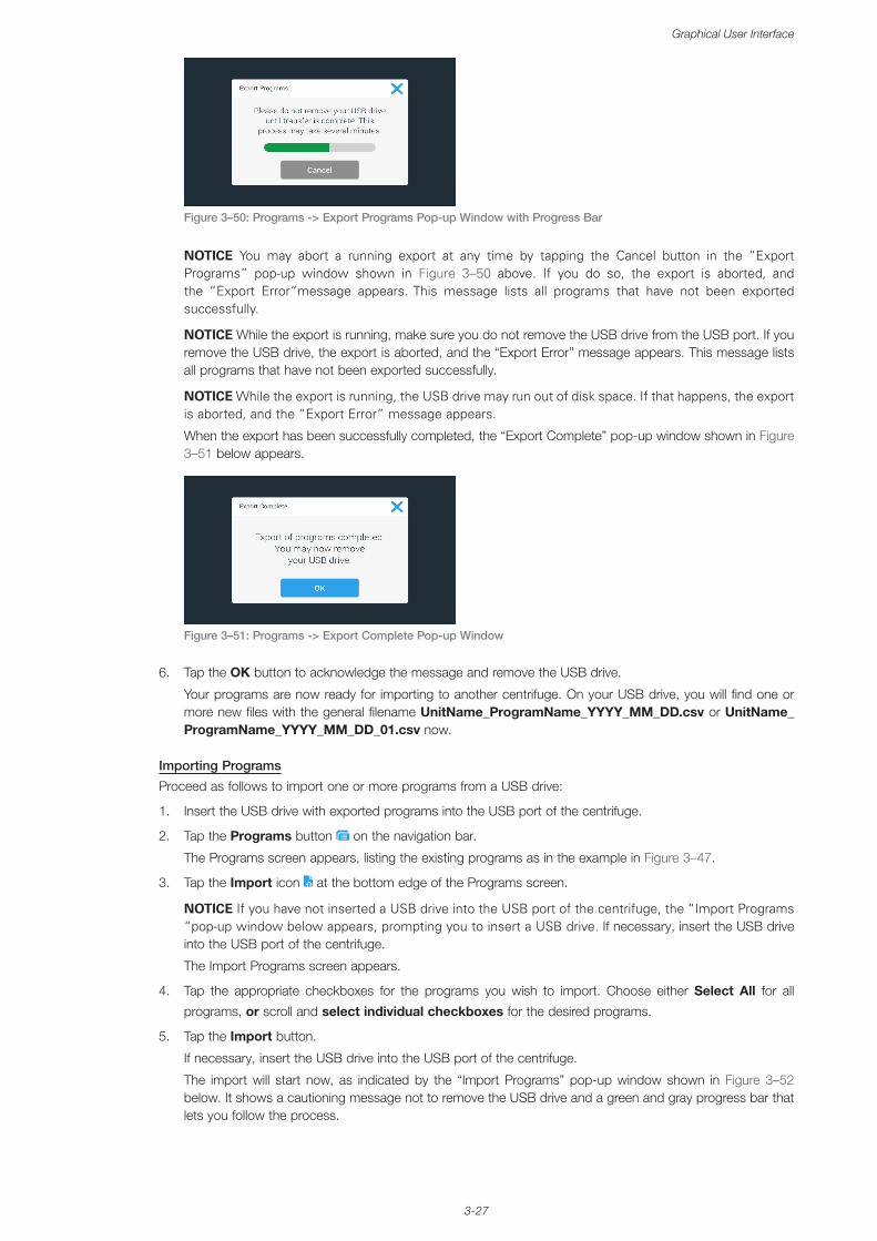
3-27
Graphical User Interface
Figure 3–50: Programs -> Export Programs Pop-up Window with Progress Bar
NOTICE You may abort a running export at any time by tapping the Cancel button in the “Export Programs” pop-up window shown in Figure 3–50 above. If you do so, the export is aborted, and the “Export Error“message appears. This message lists all programs that have not been exported successfully.
NOTICE While the export is running, make sure you do not remove the USB drive from the USB port. If you remove the USB drive, the export is aborted, and the “Export Error” message appears. This message lists all programs that have not been exported successfully.
NOTICE While the export is running, the USB drive may run out of disk space. If that happens, the export is aborted, and the “Export Error” message appears.
When the export has been successfully completed, the “Export Complete” pop-up window shown in Figure 3–51 below appears.
Figure 3–51: Programs -> Export Complete Pop-up Window
6. Tap the OK button to acknowledge the message and remove the USB drive.
Your programs are now ready for importing to another centrifuge. On your USB drive, you will find one or more new files with the general filename UnitName_ProgramName_YYYY_MM_DD.csv or UnitName_ProgramName_YYYY_MM_DD_01.csv now.
Importing Programs
Proceed as follows to import one or more programs from a USB drive:
1. Insert the USB drive with exported programs into the USB port of the centrifuge.
2. Tap the Programs button on the navigation bar.
The Programs screen appears, listing the existing programs as in the example in Figure 3–47.
3. Tap the Import icon at the bottom edge of the Programs screen.
NOTICE If you have not inserted a USB drive into the USB port of the centrifuge, the “Import Programs “pop-up window below appears, prompting you to insert a USB drive. If necessary, insert the USB drive into the USB port of the centrifuge.
The Import Programs screen appears.
4. Tap the appropriate checkboxes for the programs you wish to import. Choose either Select All for all
programs, or scroll and select individual checkboxes for the desired programs.
5. Tap the Import button.
If necessary, insert the USB drive into the USB port of the centrifuge.
The import will start now, as indicated by the “Import Programs” pop-up window shown in Figure 3–52 below. It shows a cautioning message not to remove the USB drive and a green and gray progress bar that lets you follow the process.
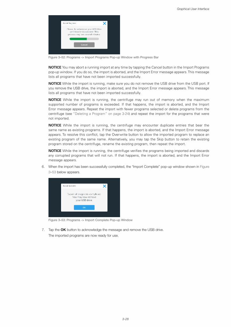
3-28
Graphical User Interface
Figure 3–52: Programs -> Import Programs Pop-up Window with Progress Bar
NOTICE You may abort a running import at any time by tapping the Cancel button in the Import Programs pop-up window. If you do so, the import is aborted, and the Import Error message appears. This message lists all programs that have not been imported successfully.
NOTICE While the import is running, make sure you do not remove the USB drive from the USB port. If you remove the USB drive, the import is aborted, and the Import Error message appears. This message lists all programs that have not been imported successfully.
NOTICE While the import is running, the centrifuge may run out of memory when the maximum supported number of programs is exceeded. If that happens, the import is aborted, and the Import Error message appears. Repeat the import with fewer programs selected or delete programs from the centrifuge (see “Deleting a Program” on page 3-24) and repeat the import for the programs that were not imported.
NOTICE While the import is running, the centrifuge may encounter duplicate entries that bear the same name as existing programs. If that happens, the import is aborted, and the Import Error message appears. To resolve this conflict, tap the Overwrite button to allow the imported program to replace an existing program of the same name. Alternatively, you may tap the Skip button to retain the existing program stored on the centrifuge, rename the existing program, then repeat the import.
NOTICE While the import is running, the centrifuge verifies the programs being imported and discards any corrupted programs that will not run. If that happens, the import is aborted, and the Import Error message appears.
6. When the import has been successfully completed, the “Import Complete” pop-up window shown in Figure
3–53 below appears.
Figure 3–53: Programs -> Import Complete Pop-up Window
7. Tap the OK button to acknowledge the message and remove the USB drive.
The imported programs are now ready for use.
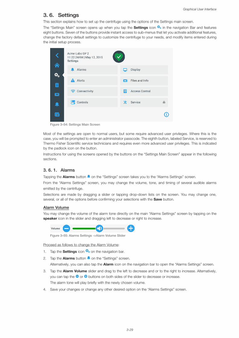
3-29
Graphical User Interface
3. 6. SettingsThis section explains how to set up the centrifuge using the options of the Settings main screen.
The “Settings Main” screen opens up when you tap the Settings icon in the navigation Bar and features eight buttons. Seven of the buttons provide instant access to sub-menus that let you activate additional features, change the factory default settings to customize the centrifuge to your needs, and modify items entered during the initial setup process.
Figure 3–54: Settings Main Screen
Most of the settings are open to normal users, but some require advanced user privileges. Where this is the case, you will be prompted to enter an administrator passcode. The eighth button, labeled Service, is reserved to Thermo Fisher Scientific service technicians and requires even more advanced user privileges. This is indicated by the padlock icon on the button.
Instructions for using the screens opened by the buttons on the “Settings Main Screen” appear in the following sections.
3. 6. 1. AlarmsTapping the Alarms button on the “Settings” screen takes you to the “Alarms Settings” screen.
From the “Alarms Settings” screen, you may change the volume, tone, and timing of several audible alarms
emitted by the centrifuge.
Selections are made by dragging a slider or tapping drop-down lists on the screen. You may change one, several, or all of the options before confirming your selections with the Save button.
Alarm VolumeYou may change the volume of the alarm tone directly on the main “Alarms Settings” screen by tapping on the speaker icon in the slider and dragging left to decrease or right to increase.
Figure 3–55: Alarms Settings ->Alarm Volume Slider
Proceed as follows to change the Alarm Volume:
1. Tap the Settings icon on the navigation bar.
2. Tap the Alarms button on the “Settings” screen.
Alternatively, you can also tap the Alarm icon on the navigation bar to open the “Alarms Settings” screen.
3. Tap the Alarm Volume slider and drag to the left to decrease and or to the right to increase. Alternatively,
you can tap the or buttons on both sides of the slider to decrease or increase.
The alarm tone will play briefly with the newly chosen volume.
4. Save your changes or change any other desired option on the “Alarms Settings” screen.
3-30
Graphical User Interface
Alarm ToneYou may change the alarm tone for the front window directly on the main “Alarms Settings” screen by just tapping on the drop-down list labeled Alarm Tone and selecting one of the three options.
NOTICE The naming of the options may differ in each country.
Proceed as follows to change the Alarm Tone:
1. Tap the Settings icon on the navigation bar.
2. Tap the Alarms button on the “Settings” screen.
Alternatively, you can also tap the Alarm icon on the navigation bar to open the “Alarms Settings” screen.
3. Tap the Alarm Tone drop-down menu and choose an option.
The selected alarm tone will play briefly.
Save your changes or change any other desired option on the “Alarms Settings” screen.
High and Low Temperature AlarmsYou may change the high and low temperature alarm thresholds (refrigerated models only) for the centrifugation chamber temperature on the main “Alarms Settings” screen by tapping on the drop-down lists labeled “High Temperature Alarm” and “Low Temperature Alarm” and selecting one of the three options. The alarm threshold is set relative to the temperature setpoint and shifts every time you change the temperature setpoint.
Proceed as follows to change the High and Low Temperature Alarms:
1. Tap the Settings icon on the navigation bar.
2. Tap the Alarms button on the settings screen.
Alternatively, you can also tap the Alarm icon on the navigation bar to open the “Alarms Settings” screen.
3. Tap the High and Low Temperature Alarms drop-down menu and choose an option.
The selected “High or Low Temperature Alarm” threshold is activated now.
4. Save your changes or change any other desired option on the “Alarms Settings” screen.
Snooze TimeoutYou may set the timeout period during which an alarm is temporarily silenced when you tap the Snooze button directly on the main “Alarms Settings” screen. This is done by tapping on the drop-down list labeled “Snooze Timeout” and selecting one of the three periods.
Proceed as follows to change the Snooze Timeout period:
1. Tap the Settings icon on the navigation bar.
2. Tap the Alarms button on the “Settings” screen.
Alternatively, you can tap the Alarm icon on the navigation bar to open the “Alarms Settings” screen.
3. Tap the Snooze Timeout drop-down menu and choose the period for which an alarm is silenced by the
Snooze button.
The time period in the “Snooze Timeout” drop-down will change to the new setting.
4. Save your changes or change any other desired option on the “Alarms Settings” screen.
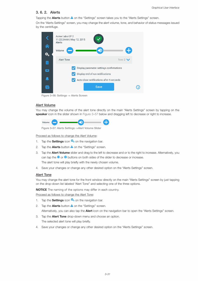
3-31
Graphical User Interface
3. 6. 2. AlertsTapping the Alerts button on the “Settings” screen takes you to the “Alerts Settings” screen.
On the “Alerts Settings” screen, you may change the alert volume, tone, and behavior of status messages issued by the centrifuge.
Figure 3–56: Settings -> Alerts Screen
Alert VolumeYou may change the volume of the alert tone directly on the main “Alerts Settings” screen by tapping on the speaker icon in the slider shown in Figure 3–57 below and dragging left to decrease or right to increase.
Figure 3–57: Alerts Settings ->Alert Volume Slider
Proceed as follows to change the Alert Volume:
1. Tap the Settings icon on the navigation bar.
2. Tap the Alerts button on the “Settings” screen.
3. Tap the Alert Volume slider and drag to the left to decrease and or to the right to increase. Alternatively, you
can tap the or buttons on both sides of the slider to decrease or increase.
The alert tone will play briefly with the newly chosen volume.
4. Save your changes or change any other desired option on the “Alerts Settings” screen.
Alert ToneYou may change the alert tone for the front window directly on the main “Alerts Settings” screen by just tapping on the drop-down list labeled “Alert Tone” and selecting one of the three options.
NOTICE The naming of the options may differ in each country.
Proceed as follows to change the Alert Tone:
1. Tap the Settings icon on the navigation bar.
2. Tap the Alerts button on the “Settings” screen.
Alternatively, you can also tap the Alert icon on the navigation bar to open the “Alerts Settings” screen.
3. Tap the Alert Tone drop-down menu and choose an option.
The selected alert tone will play briefly.
4. Save your changes or change any other desired option on the “Alerts Settings” screen.
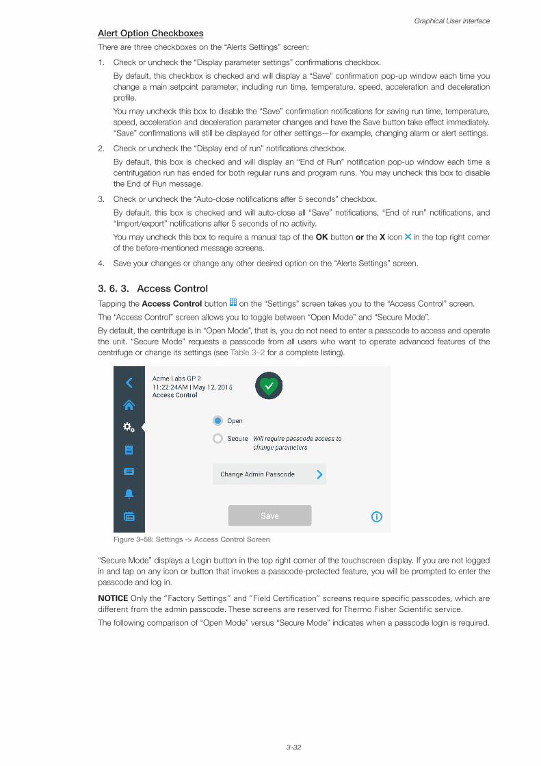
3-32
Graphical User Interface
Alert Option CheckboxesThere are three checkboxes on the “Alerts Settings” screen:
1. Check or uncheck the “Display parameter settings” confirmations checkbox.
By default, this checkbox is checked and will display a “Save” confirmation pop-up window each time you change a main setpoint parameter, including run time, temperature, speed, acceleration and deceleration profile.
You may uncheck this box to disable the “Save” confirmation notifications for saving run time, temperature, speed, acceleration and deceleration parameter changes and have the Save button take effect immediately. “Save” confirmations will still be displayed for other settings—for example, changing alarm or alert settings.
2. Check or uncheck the “Display end of run” notifications checkbox.
By default, this box is checked and will display an “End of Run” notification pop-up window each time a centrifugation run has ended for both regular runs and program runs. You may uncheck this box to disable the End of Run message.
3. Check or uncheck the “Auto-close notifications after 5 seconds” checkbox.
By default, this box is checked and will auto-close all “Save” notifications, “End of run” notifications, and “Import/export” notifications after 5 seconds of no activity.
You may uncheck this box to require a manual tap of the OK button or the X icon in the top right corner of the before-mentioned message screens.
4. Save your changes or change any other desired option on the “Alerts Settings” screen.
3. 6. 3. Access ControlTapping the Access Control button on the “Settings” screen takes you to the “Access Control” screen.
The “Access Control” screen allows you to toggle between “Open Mode” and “Secure Mode”.
By default, the centrifuge is in “Open Mode”, that is, you do not need to enter a passcode to access and operate the unit. “Secure Mode” requests a passcode from all users who want to operate advanced features of the centrifuge or change its settings (see Table 3–2 for a complete listing).
Figure 3–58: Settings -> Access Control Screen
“Secure Mode” displays a Login button in the top right corner of the touchscreen display. If you are not logged in and tap on any icon or button that invokes a passcode-protected feature, you will be prompted to enter the passcode and log in.
NOTICE Only the “Factory Settings” and “Field Certification” screens require specific passcodes, which are different from the admin passcode. These screens are reserved for Thermo Fisher Scientific service.
The following comparison of “Open Mode” versus “Secure Mode” indicates when a passcode login is required.
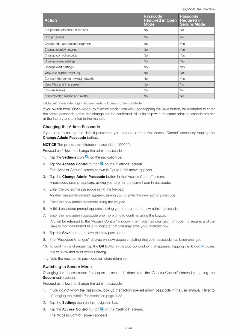
3-33
Graphical User Interface
ActionPasscode Required in Open Mode
Passcode Required in Secure Mode
Set parameters and run the unit No No
Run programs No No
Create, edit, and delete programs No Yes
Change display settings No Yes
Change control settings No Yes
Change alarm settings No Yes
Change alert settings No Yes
View and export event log No No
Connect the unit to a wired network No Yes
View Files and Info screen No No
Snooze Alarms No No
Acknowledge alarms and alerts No No
Table 3–2: Passcode Login Requirements in Open and Secure Mode
If you switch from “Open Mode” to “Secure Mode”, you will, upon tapping the Save button, be prompted to enter the admin passcode before the change can be confirmed. All units ship with the same admin passcode pre-set at the factory and printed in the manual.
Changing the Admin PasscodeIf you need to change the default passcode, you may do so from the “Access Control” screen by tapping the Change Admin Passcode button.
NOTICE The preset administrator passcode is “00000”.
Proceed as follows to change the admin passcode:
1. Tap the Settings icon on the navigation bar.
2. Tap the Access Control button on the “Settings” screen.
The “Access Control” screen shown in Figure 3–58 above appears.
3. Tap the Change Admin Passcode button in the “Access Control” screen.
A passcode prompt appears, asking you to enter the current admin passcode.
4. Enter the old admin passcode using the keypad.
Another passcode prompt appears, asking you to enter the new admin passcode.
5. Enter the new admin passcode using the keypad.
6. A third passcode prompt appears, asking you to re-enter the new admin passcode.
7. Enter the new admin passcode one more time to confirm, using the keypad.
You will be returned to the “Access Control” window. The mode has changed from open to secure, and the Save button has turned blue to indicate that you may save your changes now.
8. Tap the Save button to save the new passcode.
9. The “Passcode Changed” pop-up window appears, stating that your passcode has been changed.
10. To confirm the changes, tap the OK button in the pop-up window that appears. Tapping the X icon closes
this window and exits without saving.
11. Note the new admin passcode for future reference.
Switching to Secure ModeChanging the access mode from open to secure is done from the “Access Control” screen by tapping the Secure radio button.
Proceed as follows to change the admin passcode:
1. If you do not know the passcode, look up the factory pre-set admin passcode in the user manual. Refer to
“Changing the Admin Passcode” on page 3-33.
2. Tap the Settings icon on the navigation bar.
3. Tap the Access Control button on the “Settings” screen.
The “Access Control” screen appears.
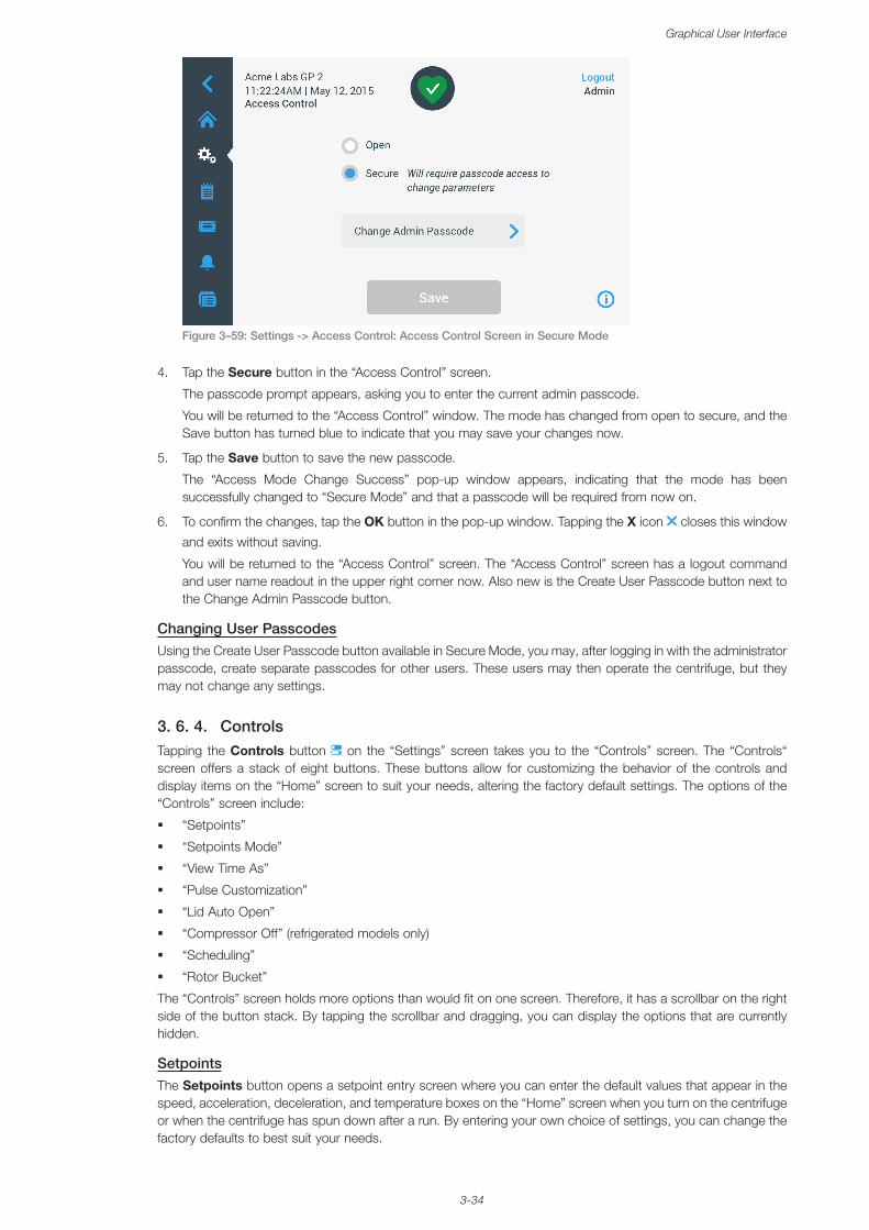
3-34
Graphical User Interface
Figure 3–59: Settings -> Access Control: Access Control Screen in Secure Mode
4. Tap the Secure button in the “Access Control” screen.
The passcode prompt appears, asking you to enter the current admin passcode.
You will be returned to the “Access Control” window. The mode has changed from open to secure, and the Save button has turned blue to indicate that you may save your changes now.
5. Tap the Save button to save the new passcode.
The “Access Mode Change Success” pop-up window appears, indicating that the mode has been successfully changed to “Secure Mode” and that a passcode will be required from now on.
6. To confirm the changes, tap the OK button in the pop-up window. Tapping the X icon closes this window
and exits without saving.
You will be returned to the “Access Control” screen. The “Access Control” screen has a logout command and user name readout in the upper right corner now. Also new is the Create User Passcode button next to the Change Admin Passcode button.
Changing User PasscodesUsing the Create User Passcode button available in Secure Mode, you may, after logging in with the administrator passcode, create separate passcodes for other users. These users may then operate the centrifuge, but they may not change any settings.
3. 6. 4. ControlsTapping the Controls button on the “Settings” screen takes you to the “Controls” screen. The “Controls“ screen offers a stack of eight buttons. These buttons allow for customizing the behavior of the controls and display items on the “Home” screen to suit your needs, altering the factory default settings. The options of the “Controls” screen include:
� “Setpoints”
� “Setpoints Mode”
� “View Time As”
� “Pulse Customization”
� “Lid Auto Open”
� “Compressor Off” (refrigerated models only)
� “Scheduling”
� “Rotor Bucket”
The “Controls” screen holds more options than would fit on one screen. Therefore, it has a scrollbar on the right side of the button stack. By tapping the scrollbar and dragging, you can display the options that are currently hidden.
SetpointsThe Setpoints button opens a setpoint entry screen where you can enter the default values that appear in the speed, acceleration, deceleration, and temperature boxes on the “Home” screen when you turn on the centrifuge or when the centrifuge has spun down after a run. By entering your own choice of settings, you can change the factory defaults to best suit your needs.
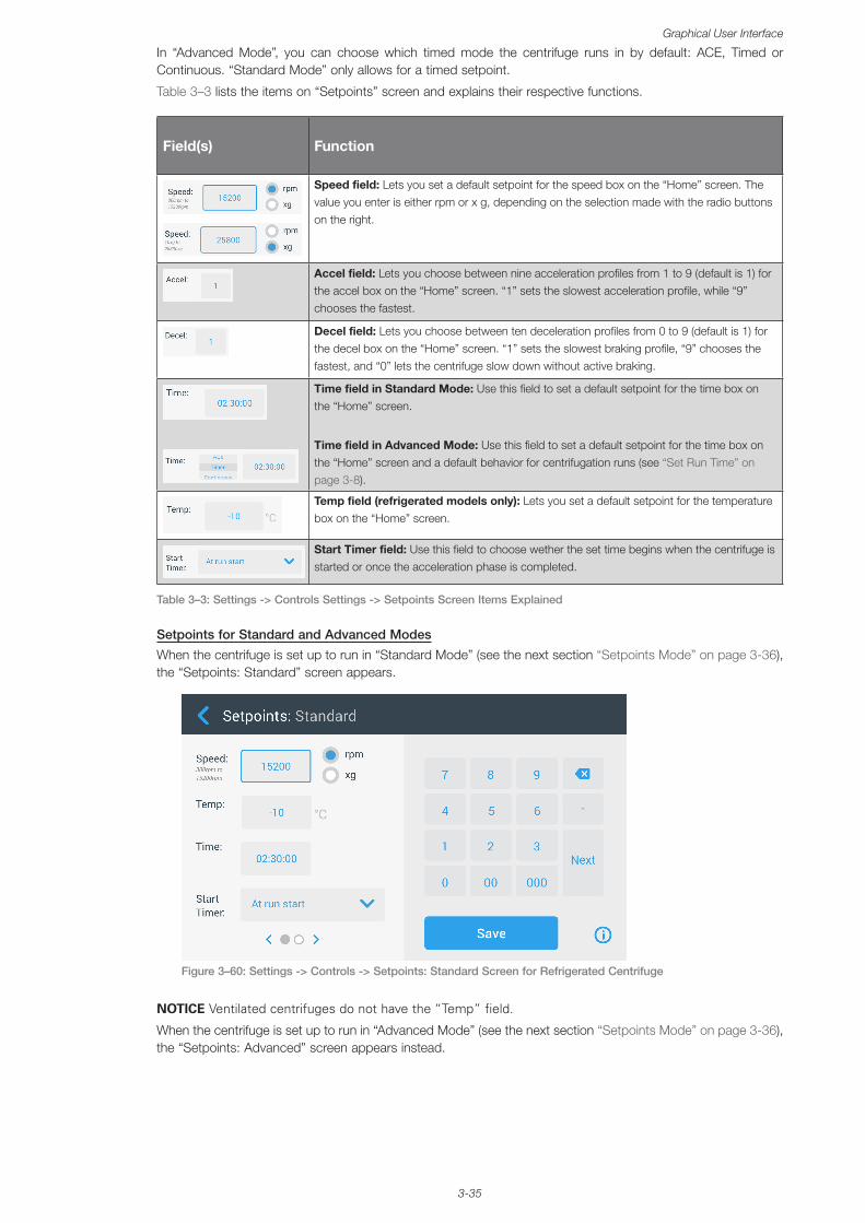
3-35
Graphical User Interface
In “Advanced Mode”, you can choose which timed mode the centrifuge runs in by default: ACE, Timed or Continuous. “Standard Mode” only allows for a timed setpoint.
Table 3–3 lists the items on “Setpoints” screen and explains their respective functions.
Field(s) Function
Speed field: Lets you set a default setpoint for the speed box on the “Home” screen. The value you enter is either rpm or x g, depending on the selection made with the radio buttons on the right.
Accel field: Lets you choose between nine acceleration profiles from 1 to 9 (default is 1) for the accel box on the “Home” screen. “1” sets the slowest acceleration profile, while “9” chooses the fastest.
Decel field: Lets you choose between ten deceleration profiles from 0 to 9 (default is 1) for the decel box on the “Home” screen. “1” sets the slowest braking profile, “9” chooses the fastest, and “0” lets the centrifuge slow down without active braking.
Time field in Standard Mode: Use this field to set a default setpoint for the time box on the “Home” screen.
Time field in Advanced Mode: Use this field to set a default setpoint for the time box on the “Home” screen and a default behavior for centrifugation runs (see “Set Run Time” on page 3-8).
Temp field (refrigerated models only): Lets you set a default setpoint for the temperature box on the “Home” screen.
Start Timer field: Use this field to choose wether the set time begins when the centrifuge is started or once the acceleration phase is completed.
Table 3–3: Settings -> Controls Settings -> Setpoints Screen Items Explained
Setpoints for Standard and Advanced Modes
When the centrifuge is set up to run in “Standard Mode” (see the next section “Setpoints Mode” on page 3-36), the “Setpoints: Standard” screen appears.
Figure 3–60: Settings -> Controls -> Setpoints: Standard Screen for Refrigerated Centrifuge
NOTICE Ventilated centrifuges do not have the “Temp” field.
When the centrifuge is set up to run in “Advanced Mode” (see the next section “Setpoints Mode” on page 3-36), the “Setpoints: Advanced” screen appears instead.
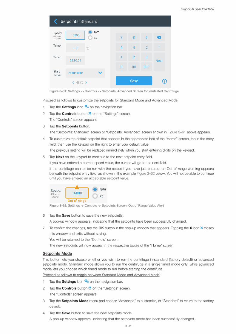
3-36
Graphical User Interface
Figure 3–61: Settings -> Controls -> Setpoints: Advanced Screen for Ventilated Centrifuge
Proceed as follows to customize the setpoints for Standard Mode and Advanced Mode:
1. Tap the Settings icon on the navigation bar.
2. Tap the Controls button on the “Settings” screen.
The “Controls” screen appears.
3. Tap the Setpoints button.
The “Setpoints: Standard” screen or “Setpoints: Advanced” screen shown in Figure 3–61 above appears.
4. To customize the default setpoint that appears in the appropriate box of the “Home” screen, tap in the entry
field, then use the keypad on the right to enter your default value.
The previous setting will be replaced immediately when you start entering digits on the keypad.
5. Tap Next on the keypad to continue to the next setpoint entry field.
If you have entered a correct speed value, the cursor will go to the next field.
If the centrifuge cannot be run with the setpoint you have just entered, an Out of range warning appears beneath the setpoint entry field, as shown in the example Figure 3–62 below. You will not be able to continue until you have entered an acceptable setpoint value.
Figure 3–62: Settings -> Controls -> Setpoints Screen: Out of Range Value Alert
6. Tap the Save button to save the new setpoint(s).
A pop-up window appears, indicating that the setpoints have been successfully changed.
7. To confirm the changes, tap the OK button in the pop-up window that appears. Tapping the X icon closes
this window and exits without saving.
You will be returned to the “Controls” screen.
The new setpoints will now appear in the respective boxes of the “Home” screen.
Setpoints ModeThis button lets you choose whether you wish to run the centrifuge in standard (factory default) or advanced setpoints mode. Standard mode allows you to run the centrifuge in a single timed mode only, while advanced mode lets you choose which timed mode to run before starting the centrifuge.
Proceed as follows to toggle between Standard Mode and Advanced Mode:
1. Tap the Settings icon on the navigation bar.
2. Tap the Controls button on the “Settings” screen.
The “Controls” screen appears.
3. Tap the Setpoints Mode menu and choose “Advanced” to customize, or “Standard” to return to the factory
default.
4. Tap the Save button to save the new setpoints mode.
A pop-up window appears, indicating that the setpoints mode has been successfully changed.
3-37
Graphical User Interface
5. To confirm the changes, tap the OK button in the pop-up window that appears. Tapping the X icon closes
this window and exits without saving.
You will be returned to the “Controls” screen.
If you have chosen “Advanced Mode”, a click-wheel with “Timed Run” options will now be added to the screen that opens when you tap the Time box on the “Home” screen.
If you have reverted to “Standard Mode”, there is no click-wheel with “Timed Run” options.
6. To further customize “Standard” or “Advanced Mode”, please refer to the previous section “Setpoints” on
page 3-34.
View Time AsThe View Time As button lets you choose whether you wish to have the counter in the time box of the “Home “screen run up or down while the centrifuge is spinning. The options are:
� Elapsed: Makes the timer run forward in continuous mode or up to the time setpoint in a timed run.
� Remaining: Makes the timer count down to zero from the time setpoint.
Proceed as follows to toggle between count-up and count-down timer modes:
1. Tap the Settings icon on the navigation bar.
2. Tap the Controls button on the “Settings” screen.
The “Controls” screen appears.
3. Tap the View Time As menu and choose Elapsed to have the timer run forwards (factory default), or
Remaining to have it run backwards.
4. Tap the Save button to save the new timer mode.
A pop-up window appears, indicating that the timer mode has been successfully changed.
5. To confirm the changes, tap the OK button in the pop-up window that appears. Tapping the X icon closes
this window and exits without saving.
You will be returned to the “Controls” screen.
Pulse CustomizationThe Pulse Customization button opens the “Pulse Customization” screen that lets you set the default behavior for the Pulse button on the “Home” screen. The following options are available for customizing the Pulse button:
� Continuous (factory default): This option makes the centrifuge run continuously at the default speed (for instructions on presetting the default speed, please refer to the section “Setpoints” on page 3-34) until you stop it by tapping the Pulse button or Stop button on the “Home” screen.
� Max speed: This option makes the centrifuge spin up to maximum speed and then stop.
� 15sec, 30sec, 1min: These options delay the start of the time counter until maximum speed has been reached.
Proceed as follows to select the default behavior for the Pulse button :
1. Tap the Settings icon on the navigation bar.
2. Tap the Controls button on the “Settings” screen.
The “Controls” screen appears.
3. Tap the Pulse Customization button.
The “Pulse Customization” screen appears.
4. Choose an option.
5. Tap the Save button to save the new mode for the Pulse button .
A pop-up window appears, indicating that the Pulse button has been successfully customized.
6. To confirm the changes, tap the OK button in the pop-up window that appears. Tapping the X icon closes
this window and exits without saving.
You will be returned to the “Controls” screen.
Lid Auto OpenThis menu lets you preset the lid of the centrifuge to remain closed or unlock automatically once the run is complete. The drop-down list has two options only:
� Yes: Lid will unlock automatically once the centrifugation run is complete.
� No: Lid will remain closed after the end of the centrifugation run.
3-38
Graphical User Interface
Proceed as follows to toggle between the auto-open and closed modes of the lid:
1. Tap the Settings icon on the navigation bar.
2. Tap the Controls button on the “Settings” screen.
The “Controls” screen appears.
3. Tap the Lid Auto Open menu and choose Yes to have the lid unlocked, or No to keep it closed (factory
default).
4. Tap the Save button to save the open/closed default setting for the lid.
A pop-up window appears, indicating that the setting has been successfully saved.
5. To confirm the changes, tap the OK button in the pop-up window that appears. Tapping the X icon closes
this window and exits without saving.
You will be returned to the “Controls” screen.
Compressor OffThe Compressor Off button opens the “Compressor Off” screen. On refrigerated centrifuges, this screen lets you set an energy-saving timer that turns off the compressor after a selectable period of inactivity.
NOTICE This screen is not present on ventilated models.
The following options are available for the compressor inactivity timer:
� Never (factory default): This option keeps the compressor running while the centrifuge is powered up, so you can tap the Pre-temp button on the Home screen and start pre-tempering of samples instantaneously.
� 30min, 1hr, 4hrs, 8hrs: These options turn off the compressor automatically after the selected period of inactivity. When you tap the Pre-temp button on the “Home” screen, you save energy but you may have to wait for the compressor to run up before the pre-tempering of your samples is started.
Proceed as follows to activate the inactivity timer for the compressor:
1. Tap the Settings icon on the navigation bar.
2. Tap the Controls button on the “Settings” screen.
The “Controls” screen appears.
3. Tap the Compressor Off button.
The “Compressor Off” screen below appears.
4. Choose an option.
5. Tap the Save button to save the new inactivity timer for the compressor.
A pop-up window appears, indicating that the timer for the compressor has been successfully set.
6. To confirm the changes, tap the OK button in the pop-up window that appears. Tapping the X icon closes
this window and exits without saving.
You will be returned to the “Controls” screen.
SchedulingThe Scheduling button takes you to the “Scheduling” screen, where you can set up the centrifuge to automatically turn on and/or off at any time of the day once per day of the week.
You can set up one “Auto On” and “Auto Off” schedule and activate one or both right away, or keep one or both disabled for later use.
Auto On Scheduling
1. Tap the Settings icon on the navigation bar.
2. Tap the Controls button on the “Settings” screen.
The “Controls” screen appears.
3. Tap the Scheduling button on the “Controls” screen.
The “Scheduling” screen appears.
If you have not configured any schedules yet, both the “Auto On” and “Auto Off” schedules will be disabled.
4. Tap the Edit button for the “Auto On” option to start setting up a schedule.
The “Edit Auto On” screen appears.
5. Tap on any day of the week—for example, M(onday).
6. Tap on AM or PM to select the period of the day
3-39
Graphical User Interface
NOTICE The AM/PM division does not appear when the radio button in the “Settings -> Display -> Time“ screen is set to 24hr (see “Time” on page 3-43 for details).
7. Tap the Time On field and enter the time of day at which you wish the centrifuge to start.
8. Tap the Temp field (refrigerated models only) and set the target temperature for pre-tempering, if desired.
NOTICE Observe the note about cooling and take precautions to ensure that the lid is closed at the specified start time.
9. Tap more days and repeat this procedure for as many days of the week as required.
10. Tap the Save button to save the new “Auto On” schedule for the centrifuge.
A pop-up window appears, alerting you to the risk of condensation pools freezing over in the centrifugation chamber.
NOTICE Observe the condensation warning and take precautions to prevent condensation from freezing in the centrifugation chamber.
11. To confirm the changes, tap the OK button in the pop-up window shown above.
You will be returned to the “Schedule” screen.
12. On the “Schedule” screen, tap the slider above the schedule field, so it changes to Enabled.
Your “Auto On” schedule is active now, the centrifuge will turn on automatically at the specified times.
Auto Off Scheduling
1. Tap the Settings icon on the navigation bar.
2. Tap the Controls button on the “Settings” screen.
The “Controls” screen appears.
3. Tap the Scheduling button on the “Controls” screen.
The “Scheduling” screen appears.
If you have not configured any schedules yet, both the “Auto On” and “Auto Off” schedules will be disabled.
4. Tap the Edit button for the “Auto Off” option to start setting up a schedule.
The “Edit Auto Off” screen appears.
5. Choose the day(s) of the week and set the stop times as described further above for “Auto On”.
6. Tap the Auto open lid checkbox to have the lid open automatically after the centrifugation run, if desired.
NOTICE Observe the notes about how an open lid interferes with “Auto On” and about the requirement to open the lid along with “Auto Off” after cooling to prevent condensation.
7. Tap more days and repeat this procedure for as many days of the week as required.
8. Tap the Save button to save the new “Auto On” schedule for the centrifuge.
If you have chosen the “Auto Open Lid” option, a pop-up window appears to alert you to the risk that an open lid interferes with the next “Auto On” schedule.
NOTICE Observe the warning about the open lid and take precautions to have the lid closed before the next “Auto Off” schedule is effective.
9. To confirm the changes, tap the OK button in the pop-up window shown above.
You will be returned to the “Schedule” screen.
10. On the “Schedule” screen, tap the slider above the schedule field, so it changes to Enabled.
Your auto-off schedule is active now. The centrifuge will turn off automatically at the specified times.
The two sliders above the “Auto On” and “Auto Off” fields read “Enabled” (see Figure 3–63).
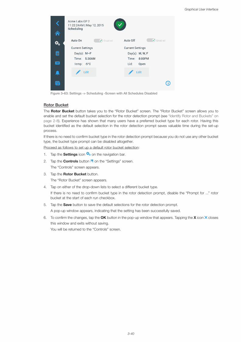
3-40
Graphical User Interface
Figure 3–63: Settings -> Scheduling -Screen with All Schedules Disabled
Rotor BucketThe Rotor Bucket button takes you to the “Rotor Bucket” screen. The “Rotor Bucket” screen allows you to enable and set the default bucket selection for the rotor detection prompt (see “Identify Rotor and Buckets” on page 2-8). Experience has shown that many users have a preferred bucket type for each rotor. Having this bucket identified as the default selection in the rotor detection prompt saves valuable time during the set-up process.
If there is no need to confirm bucket type in the rotor detection prompt because you do not use any other bucket type, the bucket type prompt can be disabled altogether.
Proceed as follows to set up a default rotor bucket selection:
1. Tap the Settings icon on the navigation bar.
2. Tap the Controls button on the “Settings” screen.
The “Controls” screen appears.
3. Tap the Rotor Bucket button.
The “Rotor Bucket” screen appears.
4. Tap on either of the drop-down lists to select a different bucket type.
If there is no need to confirm bucket type in the rotor detection prompt, disable the “Prompt for ...” rotor bucket at the start of each run checkbox.
5. Tap the Save button to save the default selections for the rotor detection prompt.
A pop-up window appears, indicating that the setting has been successfully saved.
6. To confirm the changes, tap the OK button in the pop-up window that appears. Tapping the X icon closes
this window and exits without saving.
You will be returned to the “Controls” screen.
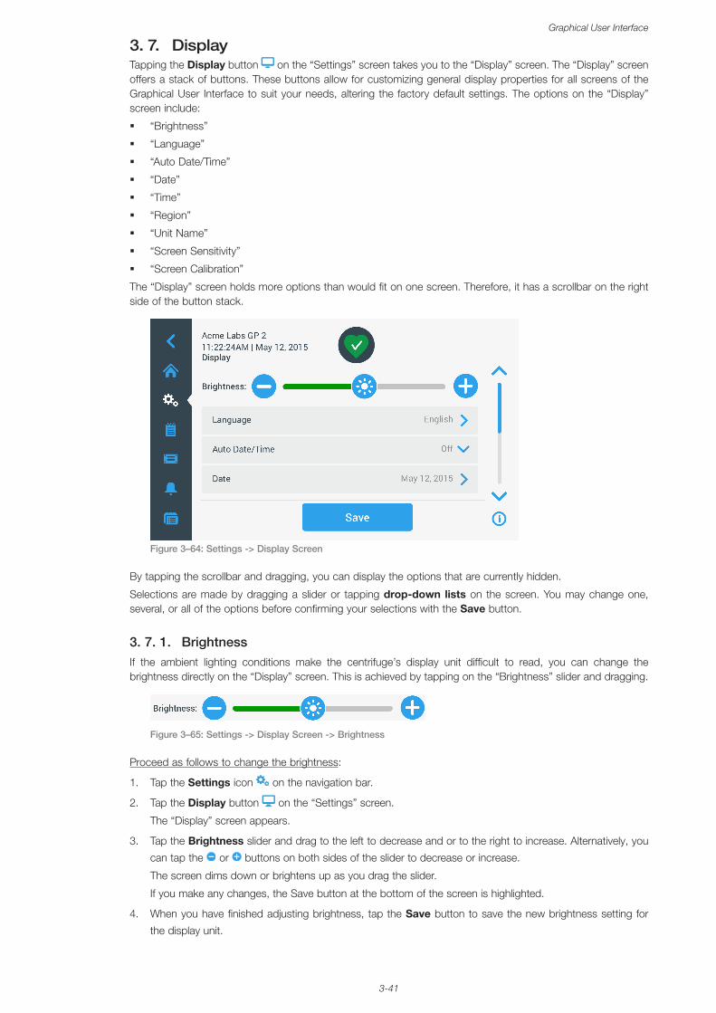
3-41
Graphical User Interface
3. 7. DisplayTapping the Display button on the “Settings” screen takes you to the “Display” screen. The “Display” screen offers a stack of buttons. These buttons allow for customizing general display properties for all screens of the Graphical User Interface to suit your needs, altering the factory default settings. The options on the “Display” screen include:
� “Brightness”
� “Language”
� “Auto Date/Time”
� “Date”
� “Time”
� “Region”
� “Unit Name”
� “Screen Sensitivity”
� “Screen Calibration”
The “Display” screen holds more options than would fit on one screen. Therefore, it has a scrollbar on the right side of the button stack.
Figure 3–64: Settings -> Display Screen
By tapping the scrollbar and dragging, you can display the options that are currently hidden.
Selections are made by dragging a slider or tapping drop-down lists on the screen. You may change one, several, or all of the options before confirming your selections with the Save button.
3. 7. 1. BrightnessIf the ambient lighting conditions make the centrifuge’s display unit difficult to read, you can change the brightness directly on the “Display” screen. This is achieved by tapping on the “Brightness” slider and dragging.
Figure 3–65: Settings -> Display Screen -> Brightness
Proceed as follows to change the brightness:
1. Tap the Settings icon on the navigation bar.
2. Tap the Display button on the “Settings” screen.
The “Display” screen appears.
3. Tap the Brightness slider and drag to the left to decrease and or to the right to increase. Alternatively, you
can tap the or buttons on both sides of the slider to decrease or increase.
The screen dims down or brightens up as you drag the slider.
If you make any changes, the Save button at the bottom of the screen is highlighted.
4. When you have finished adjusting brightness, tap the Save button to save the new brightness setting for
the display unit.
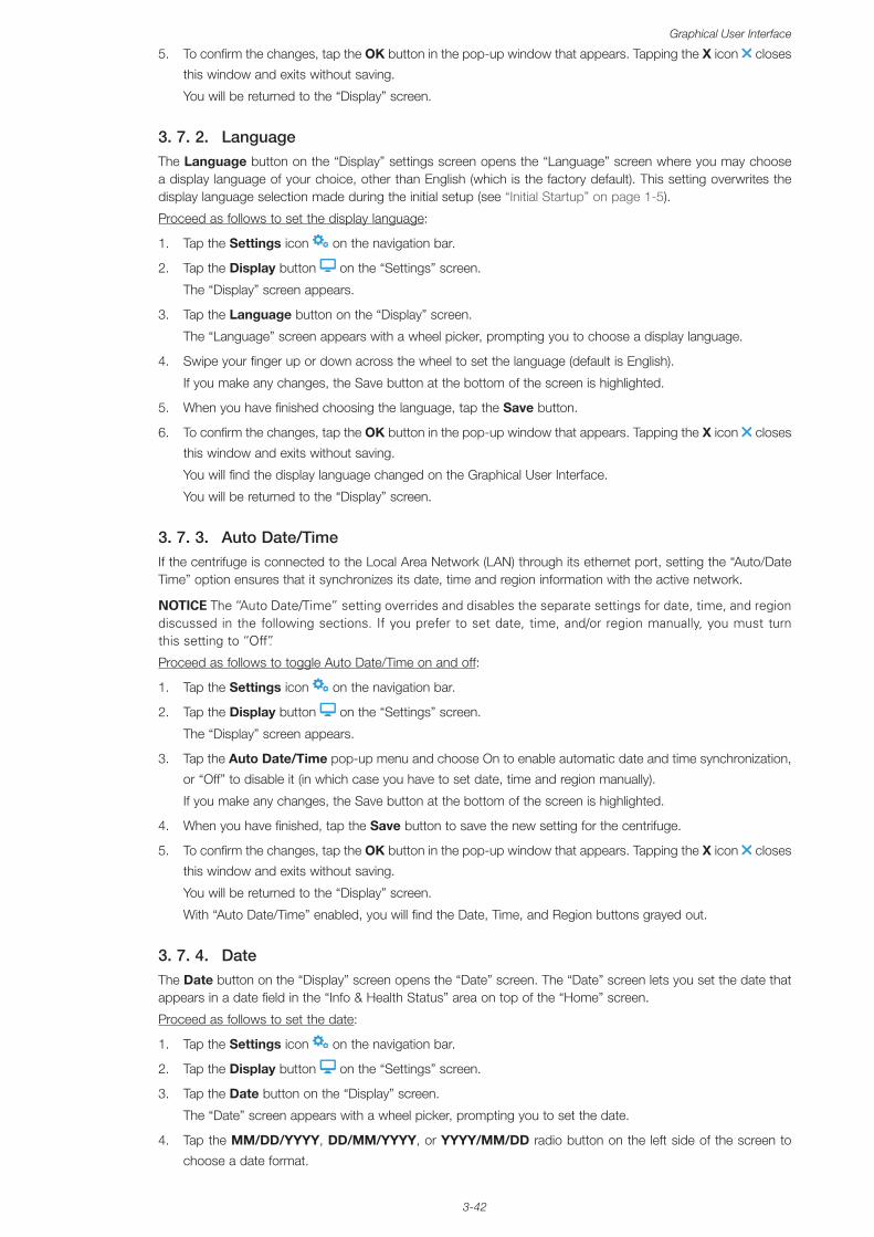
3-42
Graphical User Interface
5. To confirm the changes, tap the OK button in the pop-up window that appears. Tapping the X icon closes
this window and exits without saving.
You will be returned to the “Display” screen.
3. 7. 2. LanguageThe Language button on the “Display” settings screen opens the “Language” screen where you may choose a display language of your choice, other than English (which is the factory default). This setting overwrites the display language selection made during the initial setup (see “Initial Startup” on page 1-5).
Proceed as follows to set the display language:
1. Tap the Settings icon on the navigation bar.
2. Tap the Display button on the “Settings” screen.
The “Display” screen appears.
3. Tap the Language button on the “Display” screen.
The “Language” screen appears with a wheel picker, prompting you to choose a display language.
4. Swipe your finger up or down across the wheel to set the language (default is English).
If you make any changes, the Save button at the bottom of the screen is highlighted.
5. When you have finished choosing the language, tap the Save button.
6. To confirm the changes, tap the OK button in the pop-up window that appears. Tapping the X icon closes
this window and exits without saving.
You will find the display language changed on the Graphical User Interface.
You will be returned to the “Display” screen.
3. 7. 3. Auto Date/TimeIf the centrifuge is connected to the Local Area Network (LAN) through its ethernet port, setting the “Auto/Date Time” option ensures that it synchronizes its date, time and region information with the active network.
NOTICE The “Auto Date/Time” setting overrides and disables the separate settings for date, time, and region discussed in the following sections. If you prefer to set date, time, and/or region manually, you must turn this setting to “Off”.
Proceed as follows to toggle Auto Date/Time on and off:
1. Tap the Settings icon on the navigation bar.
2. Tap the Display button on the “Settings” screen.
The “Display” screen appears.
3. Tap the Auto Date/Time pop-up menu and choose On to enable automatic date and time synchronization,
or “Off” to disable it (in which case you have to set date, time and region manually).
If you make any changes, the Save button at the bottom of the screen is highlighted.
4. When you have finished, tap the Save button to save the new setting for the centrifuge.
5. To confirm the changes, tap the OK button in the pop-up window that appears. Tapping the X icon closes
this window and exits without saving.
You will be returned to the “Display” screen.
With “Auto Date/Time” enabled, you will find the Date, Time, and Region buttons grayed out.
3. 7. 4. DateThe Date button on the “Display” screen opens the “Date” screen. The “Date” screen lets you set the date that appears in a date field in the “Info & Health Status” area on top of the “Home” screen.
Proceed as follows to set the date:
1. Tap the Settings icon on the navigation bar.
2. Tap the Display button on the “Settings” screen.
3. Tap the Date button on the “Display” screen.
The “Date” screen appears with a wheel picker, prompting you to set the date.
4. Tap the MM/DD/YYYY, DD/MM/YYYY, or YYYY/MM/DD radio button on the left side of the screen to
choose a date format.
3-43
Graphical User Interface
The segments of the wheel picker screen are rearranged to reflect the selected date format. For example, if you select the DD/MM/YYYY radio button, the wheel picker will change to 28 | Jul | 2018.
5. Tap the up/down arrows or swipe your finger up or down across the wheel to set the current month, day,
and year on each of the three wheel picker segments.
If you have made any changes, the Save button at the bottom of the screen is highlighted.
6. When you have finished setting the date, tap the Save button.
7. To confirm the changes, tap the OK button in the pop-up window that appears. Tapping the X icon closes this window and exits without saving.
You will be returned to the “Display” screen.
3. 7. 5. TimeThe Time button on the “Display” screen opens the “Time” screen. The “Time” screen lets you set the time of day that appears in a time field in the “Info & Health Status” area on top of the “Home” screen.
Proceed as follows to set the date:
1. Tap the Settings icon on the navigation bar.
2. Tap the Display button on the “Settings” screen.
3. Tap the Time button on the “Display” screen.
The “Time” screen appears with a three-segmented wheel picker, prompting you to set the time of day.
4. If desired, tap the 24hr Display radio button on the left side of the screen to choose the Central European Time (CET; 24-hour) time format. (Default time format is AM/PM, 12-hour format.)
The segments of the wheel picker screen are rearranged to reflect the Central European Time (CET; 24-hour) time format.
5. Tap the up/down arrows or swipe your finger across each wheel up or down to set the current time in hours and minutes.
If you have made any changes, the Save button at the bottom of the screen is highlighted.
6. When you have finished setting the time of day, tap the Save button.
7. To confirm the changes, tap the OK button in the pop-up window that appears. Tapping the X icon closes this window and exits without saving.
You will be returned to the “Display” screen.
3. 7. 6. RegionThe Region button on the “Display” screen opens the “Region” screen. The “Region” screen lets you set the region for your lab location to ensure that Daylight Saving Time (DST) is observed in the time-of-day displays of the centrifuge, and that the time of day is automatically updated when DST changes.
It saves you the trouble of having to change to daylight saving time and back twice a year and keeps the event log and charting data accurate.
Proceed as follows to select your region:
1. Tap the Settings icon on the navigation bar.
2. Tap the Display button on the “Settings” screen.
3. Tap the Region button on the “Display” screen.
The “Region” screen appears, prompting you to enter the region where your site is located and specify whether DST is applicable.
4. Tap on the City/Country field and type the first three letters of the next larger city.
The system will automatically start to look ahead after three letters and propose a list of matching cities and countries.
If you type or select a city and country that does not use DST, the system also automatically deselects the “Adjust for Daylight Saving Time” checkbox.
5. If you wish to disable DST explicitly, deselect the “Adjust for Daylight Saving Time” checkbox. (The default setting is on.)
If you have made any changes, the Save button at the bottom of the screen is highlighted.
6. When you have finished setting the time of day, tap the Save button.
7. To confirm the changes, tap the OK button in the pop-up window that appears. Tapping the X icon closes this window and exits without saving.
You will be returned to the “Display” screen.
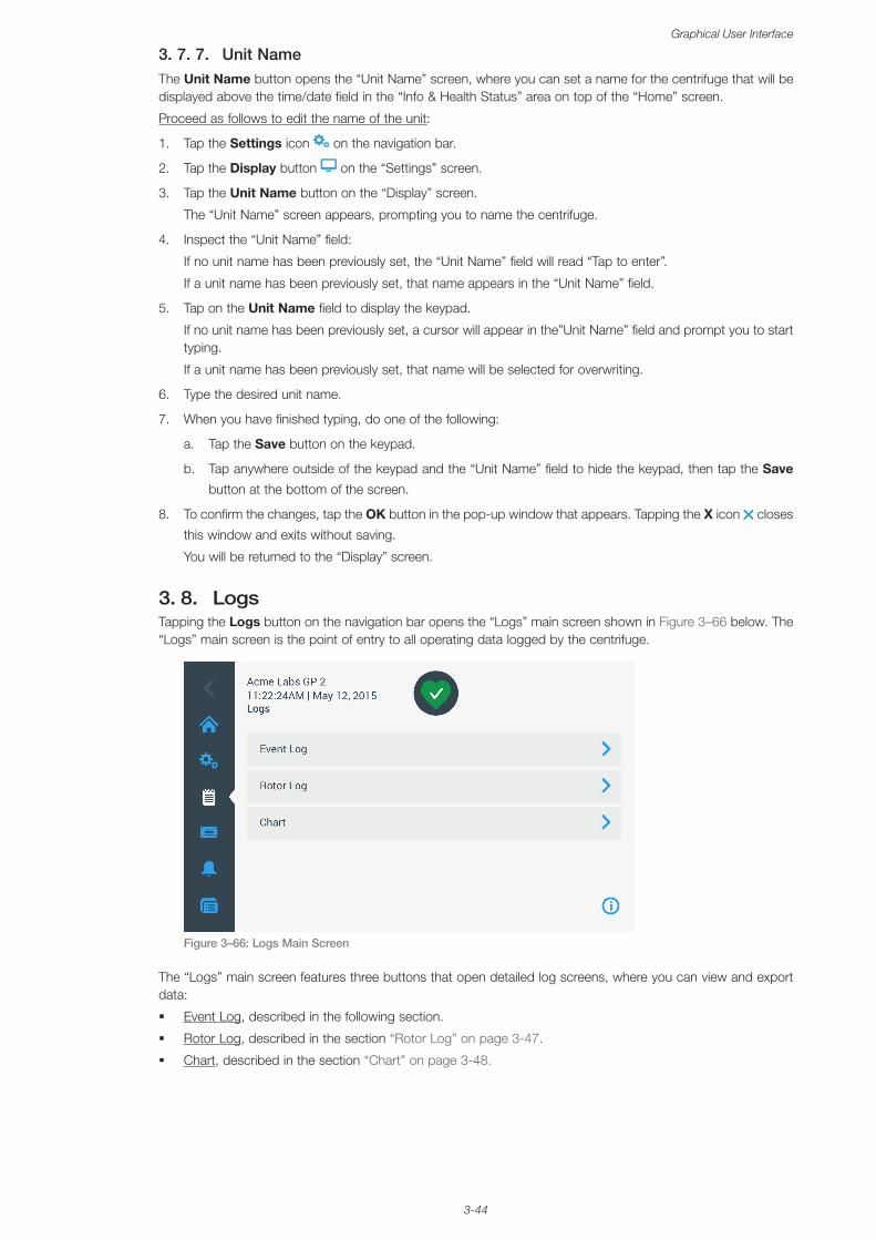
3-44
Graphical User Interface
3. 7. 7. Unit NameThe Unit Name button opens the “Unit Name” screen, where you can set a name for the centrifuge that will be displayed above the time/date field in the “Info & Health Status” area on top of the “Home” screen.
Proceed as follows to edit the name of the unit:
1. Tap the Settings icon on the navigation bar.
2. Tap the Display button on the “Settings” screen.
3. Tap the Unit Name button on the “Display” screen.
The “Unit Name” screen appears, prompting you to name the centrifuge.
4. Inspect the “Unit Name” field:
If no unit name has been previously set, the “Unit Name” field will read “Tap to enter”.
If a unit name has been previously set, that name appears in the “Unit Name” field.
5. Tap on the Unit Name field to display the keypad.
If no unit name has been previously set, a cursor will appear in the”Unit Name” field and prompt you to start typing.
If a unit name has been previously set, that name will be selected for overwriting.
6. Type the desired unit name.
7. When you have finished typing, do one of the following:
a. Tap the Save button on the keypad.
b. Tap anywhere outside of the keypad and the “Unit Name” field to hide the keypad, then tap the Save
button at the bottom of the screen.
8. To confirm the changes, tap the OK button in the pop-up window that appears. Tapping the X icon closes
this window and exits without saving.
You will be returned to the “Display” screen.
3. 8. LogsTapping the Logs button on the navigation bar opens the “Logs” main screen shown in Figure 3–66 below. The “Logs” main screen is the point of entry to all operating data logged by the centrifuge.
Figure 3–66: Logs Main Screen
The “Logs” main screen features three buttons that open detailed log screens, where you can view and export data:
� Event Log, described in the following section.
� Rotor Log, described in the section “Rotor Log” on page 3-47.
� Chart, described in the section “Chart” on page 3-48.
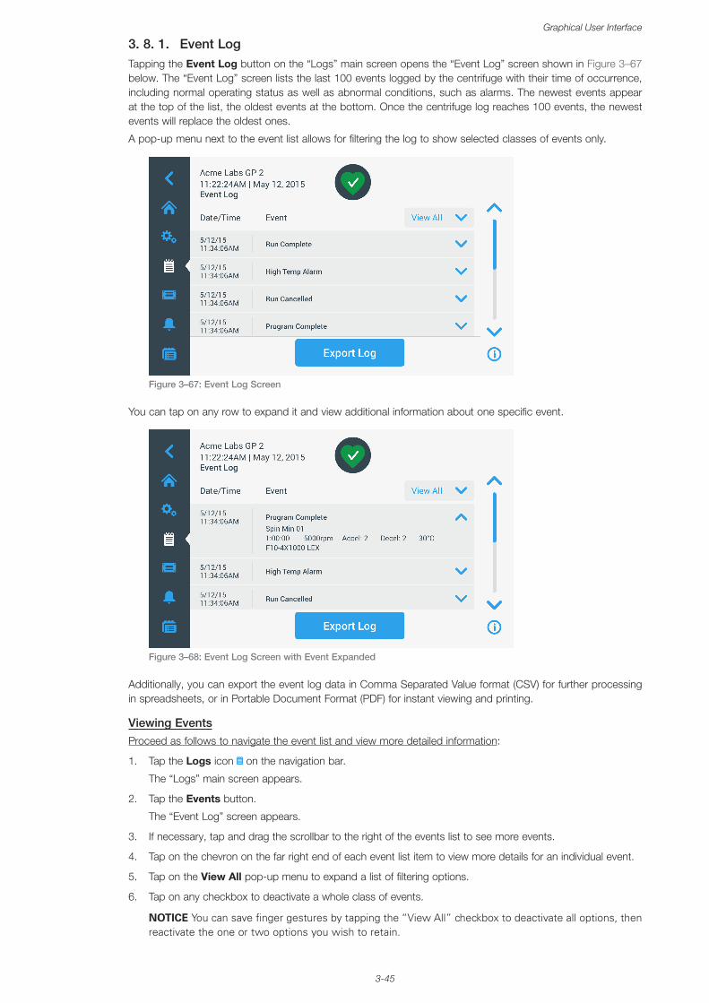
3-45
Graphical User Interface
3. 8. 1. Event LogTapping the Event Log button on the “Logs” main screen opens the “Event Log” screen shown in Figure 3–67 below. The “Event Log” screen lists the last 100 events logged by the centrifuge with their time of occurrence, including normal operating status as well as abnormal conditions, such as alarms. The newest events appear at the top of the list, the oldest events at the bottom. Once the centrifuge log reaches 100 events, the newest events will replace the oldest ones.
A pop-up menu next to the event list allows for filtering the log to show selected classes of events only.
Figure 3–67: Event Log Screen
You can tap on any row to expand it and view additional information about one specific event.
Figure 3–68: Event Log Screen with Event Expanded
Additionally, you can export the event log data in Comma Separated Value format (CSV) for further processing in spreadsheets, or in Portable Document Format (PDF) for instant viewing and printing.
Viewing EventsProceed as follows to navigate the event list and view more detailed information:
1. Tap the Logs icon on the navigation bar.
The “Logs” main screen appears.
2. Tap the Events button.
The “Event Log” screen appears.
3. If necessary, tap and drag the scrollbar to the right of the events list to see more events.
4. Tap on the chevron on the far right end of each event list item to view more details for an individual event.
5. Tap on the View All pop-up menu to expand a list of filtering options.
6. Tap on any checkbox to deactivate a whole class of events.
NOTICE You can save finger gestures by tapping the “View All” checkbox to deactivate all options, then reactivate the one or two options you wish to retain.
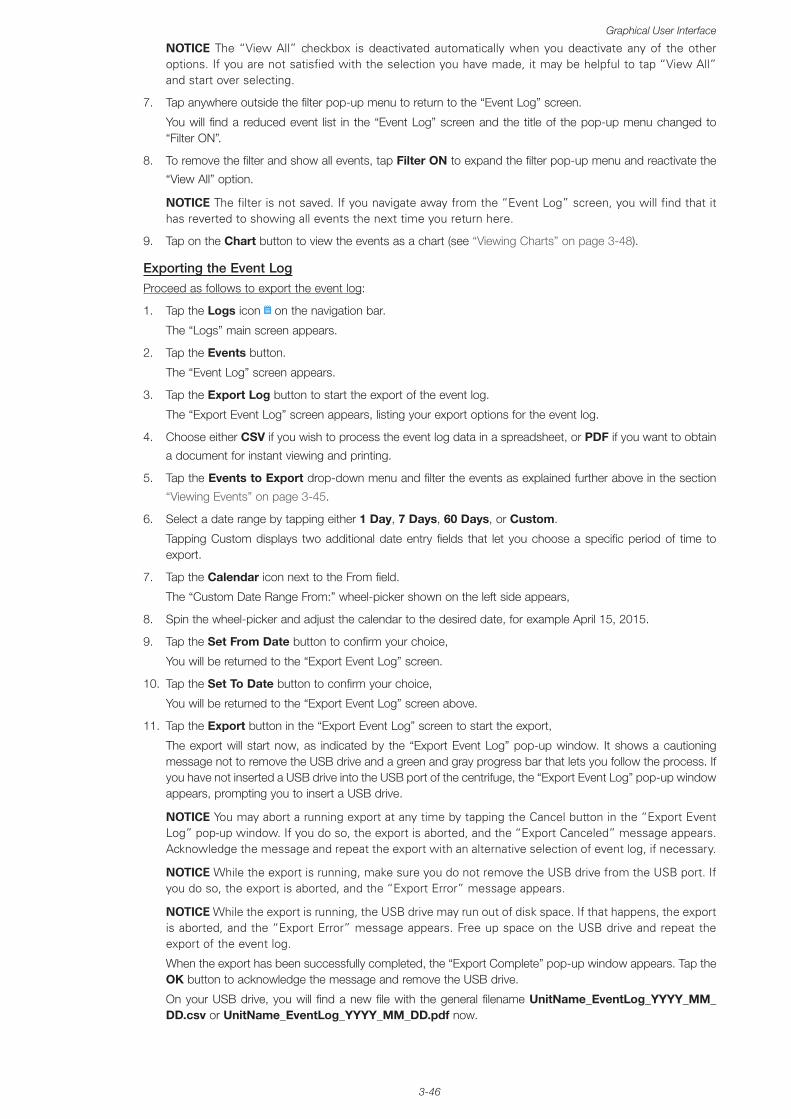
3-46
Graphical User Interface
NOTICE The “View All” checkbox is deactivated automatically when you deactivate any of the other options. If you are not satisfied with the selection you have made, it may be helpful to tap “View All” and start over selecting.
7. Tap anywhere outside the filter pop-up menu to return to the “Event Log” screen.
You will find a reduced event list in the “Event Log” screen and the title of the pop-up menu changed to “Filter ON”.
8. To remove the filter and show all events, tap Filter ON to expand the filter pop-up menu and reactivate the
“View All” option.
NOTICE The filter is not saved. If you navigate away from the “Event Log” screen, you will find that it has reverted to showing all events the next time you return here.
9. Tap on the Chart button to view the events as a chart (see “Viewing Charts” on page 3-48).
Exporting the Event LogProceed as follows to export the event log:
1. Tap the Logs icon on the navigation bar.
The “Logs” main screen appears.
2. Tap the Events button.
The “Event Log” screen appears.
3. Tap the Export Log button to start the export of the event log.
The “Export Event Log” screen appears, listing your export options for the event log.
4. Choose either CSV if you wish to process the event log data in a spreadsheet, or PDF if you want to obtain
a document for instant viewing and printing.
5. Tap the Events to Export drop-down menu and filter the events as explained further above in the section
“Viewing Events” on page 3-45.
6. Select a date range by tapping either 1 Day, 7 Days, 60 Days, or Custom.
Tapping Custom displays two additional date entry fields that let you choose a specific period of time to export.
7. Tap the Calendar icon next to the From field.
The “Custom Date Range From:” wheel-picker shown on the left side appears,
8. Spin the wheel-picker and adjust the calendar to the desired date, for example April 15, 2015.
9. Tap the Set From Date button to confirm your choice,
You will be returned to the “Export Event Log” screen.
10. Tap the Set To Date button to confirm your choice,
You will be returned to the “Export Event Log” screen above.
11. Tap the Export button in the “Export Event Log” screen to start the export,
The export will start now, as indicated by the “Export Event Log” pop-up window. It shows a cautioning message not to remove the USB drive and a green and gray progress bar that lets you follow the process. If you have not inserted a USB drive into the USB port of the centrifuge, the “Export Event Log” pop-up window appears, prompting you to insert a USB drive.
NOTICE You may abort a running export at any time by tapping the Cancel button in the “Export Event Log” pop-up window. If you do so, the export is aborted, and the “Export Canceled” message appears. Acknowledge the message and repeat the export with an alternative selection of event log, if necessary.
NOTICE While the export is running, make sure you do not remove the USB drive from the USB port. If you do so, the export is aborted, and the “Export Error” message appears.
NOTICE While the export is running, the USB drive may run out of disk space. If that happens, the export is aborted, and the “Export Error” message appears. Free up space on the USB drive and repeat the export of the event log.
When the export has been successfully completed, the “Export Complete” pop-up window appears. Tap the OK button to acknowledge the message and remove the USB drive.
On your USB drive, you will find a new file with the general filename UnitName_EventLog_YYYY_MM_DD.csv or UnitName_EventLog_YYYY_MM_DD.pdf now.
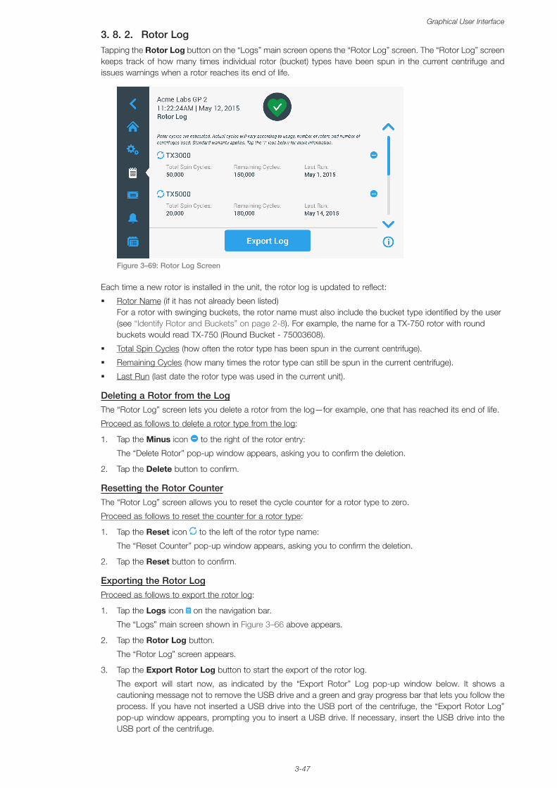
3-47
Graphical User Interface
3. 8. 2. Rotor LogTapping the Rotor Log button on the “Logs” main screen opens the “Rotor Log” screen. The “Rotor Log” screen keeps track of how many times individual rotor (bucket) types have been spun in the current centrifuge and issues warnings when a rotor reaches its end of life.
Figure 3–69: Rotor Log Screen
Each time a new rotor is installed in the unit, the rotor log is updated to reflect:
� Rotor Name (if it has not already been listed) For a rotor with swinging buckets, the rotor name must also include the bucket type identified by the user (see “Identify Rotor and Buckets” on page 2-8). For example, the name for a TX-750 rotor with round buckets would read TX-750 (Round Bucket - 75003608).
� Total Spin Cycles (how often the rotor type has been spun in the current centrifuge).
� Remaining Cycles (how many times the rotor type can still be spun in the current centrifuge).
� Last Run (last date the rotor type was used in the current unit).
Deleting a Rotor from the LogThe “Rotor Log” screen lets you delete a rotor from the log—for example, one that has reached its end of life.
Proceed as follows to delete a rotor type from the log:
1. Tap the Minus icon to the right of the rotor entry:
The “Delete Rotor” pop-up window appears, asking you to confirm the deletion.
2. Tap the Delete button to confirm.
Resetting the Rotor CounterThe “Rotor Log” screen allows you to reset the cycle counter for a rotor type to zero.
Proceed as follows to reset the counter for a rotor type:
1. Tap the Reset icon to the left of the rotor type name:
The “Reset Counter” pop-up window appears, asking you to confirm the deletion.
2. Tap the Reset button to confirm.
Exporting the Rotor LogProceed as follows to export the rotor log:
1. Tap the Logs icon on the navigation bar.
The “Logs” main screen shown in Figure 3–66 above appears.
2. Tap the Rotor Log button.
The “Rotor Log” screen appears.
3. Tap the Export Rotor Log button to start the export of the rotor log.
The export will start now, as indicated by the “Export Rotor” Log pop-up window below. It shows a cautioning message not to remove the USB drive and a green and gray progress bar that lets you follow the process. If you have not inserted a USB drive into the USB port of the centrifuge, the “Export Rotor Log” pop-up window appears, prompting you to insert a USB drive. If necessary, insert the USB drive into the USB port of the centrifuge.
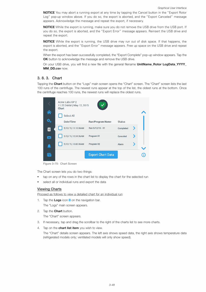
3-48
Graphical User Interface
NOTICE You may abort a running export at any time by tapping the Cancel button in the “Export Rotor Log“ pop-up window above. If you do so, the export is aborted, and the “Export Canceled” message appears. Acknowledge the message and repeat the export, if necessary.
NOTICE While the export is running, make sure you do not remove the USB drive from the USB port. If you do so, the export is aborted, and the “Export Error” message appears. Reinsert the USB drive and repeat the export.
NOTICE While the export is running, the USB drive may run out of disk space. If that happens, the export is aborted, and the “Export Error” message appears. Free up space on the USB drive and repeat the export.
When the export has been successfully completed, the “Export Complete” pop-up window appears. Tap the OK button to acknowledge the message and remove the USB drive.
On your USB drive, you will find a new file with the general filename UnitName_Rotor LogData_YYYY_MM_DD.csv now.
3. 8. 3. ChartTapping the Chart button on the “Logs” main screen opens the “Chart” screen. The “Chart” screen lists the last 100 runs of the centrifuge. The newest runs appear at the top of the list, the oldest runs at the bottom. Once the centrifuge reaches 100 runs, the newest runs will replace the oldest runs.
Figure 3–70: Chart Screen
The Chart screen lets you do two things:
� tap on any of the rows in the chart list to display the chart for the selected run
� select all or individual runs and export the data
Viewing ChartsProceed as follows to view a detailed chart for an individual run:
1. Tap the Logs icon on the navigation bar.
The “Logs” main screen appears.
2. Tap the Chart button.
The “Chart” screen appears.
3. If necessary, tap and drag the scrollbar to the right of the charts list to see more charts.
4. Tap on the chart list item you wish to view.
The “Chart” details screen appears. The left axis shows speed data, the right axis shows temperature data (refrigerated models only; ventilated models will only show speed).
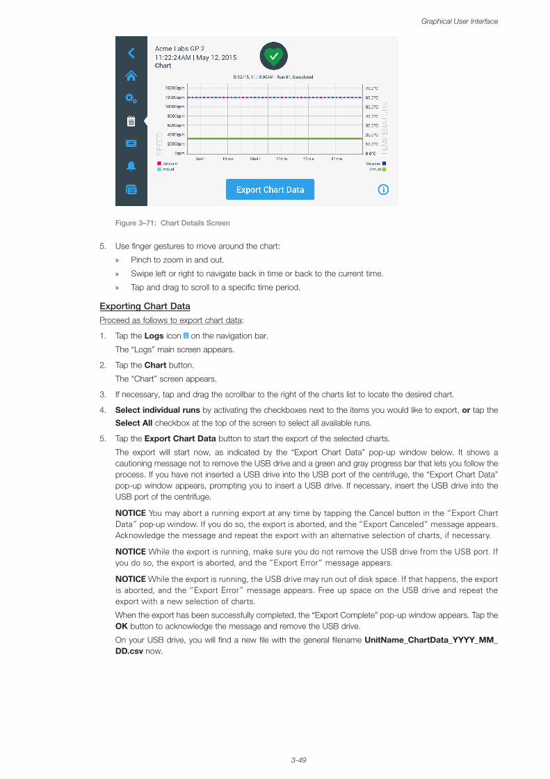
3-49
Graphical User Interface
Figure 3–71: Chart Details Screen
5. Use finger gestures to move around the chart:
» Pinch to zoom in and out.
» Swipe left or right to navigate back in time or back to the current time.
» Tap and drag to scroll to a specific time period.
Exporting Chart DataProceed as follows to export chart data:
1. Tap the Logs icon on the navigation bar.
The “Logs” main screen appears.
2. Tap the Chart button.
The “Chart” screen appears.
3. If necessary, tap and drag the scrollbar to the right of the charts list to locate the desired chart.
4. Select individual runs by activating the checkboxes next to the items you would like to export, or tap the
Select All checkbox at the top of the screen to select all available runs.
5. Tap the Export Chart Data button to start the export of the selected charts.
The export will start now, as indicated by the “Export Chart Data” pop-up window below. It shows a cautioning message not to remove the USB drive and a green and gray progress bar that lets you follow the process. If you have not inserted a USB drive into the USB port of the centrifuge, the “Export Chart Data” pop-up window appears, prompting you to insert a USB drive. If necessary, insert the USB drive into the USB port of the centrifuge.
NOTICE You may abort a running export at any time by tapping the Cancel button in the “Export Chart Data” pop-up window. If you do so, the export is aborted, and the “Export Canceled” message appears. Acknowledge the message and repeat the export with an alternative selection of charts, if necessary.
NOTICE While the export is running, make sure you do not remove the USB drive from the USB port. If you do so, the export is aborted, and the “Export Error” message appears.
NOTICE While the export is running, the USB drive may run out of disk space. If that happens, the export is aborted, and the “Export Error” message appears. Free up space on the USB drive and repeat the export with a new selection of charts.
When the export has been successfully completed, the “Export Complete” pop-up window appears. Tap the OK button to acknowledge the message and remove the USB drive.
On your USB drive, you will find a new file with the general filename UnitName_ChartData_YYYY_MM_DD.csv now.
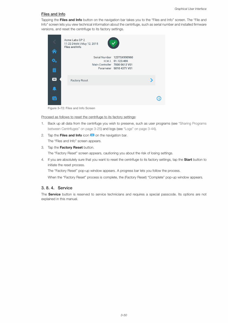
3-50
Graphical User Interface
Files and InfoTapping the Files and Info button on the navigation bar takes you to the “Files and Info” screen. The “File and Info” screen lets you view technical information about the centrifuge, such as serial number and installed firmware versions, and reset the centrifuge to its factory settings.
Figure 3–72: Files and Info Screen
Proceed as follows to reset the centrifuge to its factory settings:
1. Back up all data from the centrifuge you wish to preserve, such as user programs (see “Sharing Programs
between Centrifuges” on page 3-25) and logs (see “Logs” on page 3-44).
2. Tap the Files and Info icon on the navigation bar.
The “Files and Info” screen appears.
3. Tap the Factory Reset button.
The “Factory Reset” screen appears, cautioning you about the risk of losing settings.
4. If you are absolutely sure that you want to reset the centrifuge to its factory settings, tap the Start button to
initiate the reset process.
The “Factory Reset” pop-up window appears. A progress bar lets you follow the process.
When the “Factory Reset” process is complete, the (Factory Reset) “Complete” pop-up window appears.
3. 8. 4. ServiceThe Service button is reserved to service technicians and requires a special passcode. Its options are not explained in this manual.
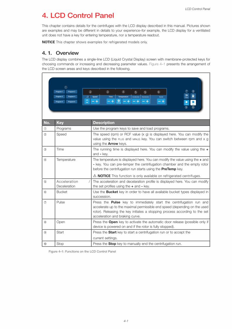
4-1
LCD Control Panel
4. LCD Control PanelThis chapter contains details for the centrifuges with the LCD display described in this manual. Pictures shown are examples and may be different in details to your experience–for example, the LCD display for a ventilated unit does not have a key for entering temperature, nor a temperature readout.
NOTICE This chapter shows examples for refrigerated models only.
4. 1. OverviewThe LCD display combines a single-line LCD (Liquid Crystal Display) screen with membrane-protected keys for choosing commands or increasing and decreasing parameter values. Figure 4–1 presents the arrangement of the LCD screen areas and keys described in the following.
➁
➀➆ ➇
➉
➅➂ ➄➃
➈
➄
No. Key Description➀ Programs Use the program keys to save and load programs.
➁ Speed The speed (rpm) or RCF value (x g) is displayed here. You can modify the value using the plus and minus key. You can switch between rpm and x g using the Arrow keys.
➂ Time The running time is displayed here. You can modify the value using the + and - key.
➃ Temperature The temperature is displayed here. You can modify the value using the + and - key. You can pre-temper the centrifugation chamber and the empty rotor before the centrifugation run starts using the PreTemp key.
A NOTICE This function is only available on refrigerated centrifuges.
➄ Acceleration / Deceleration
The acceleration and decelaration profile is displayed here. You can modify the set profiles using the + and - key.
➅ Bucket Use the Bucket key in order to have all available bucket types displayed in succession.
➆ Pulse Press the Pulse key to immediately start the centrifugation run and accelerate up to the maximal permissible end speed (depending on the used rotor). Releasing the key initiates a stopping process according to the set acceleration and braking curve.
➇ Open Press the Open key to activate the automatic door release (possible only if device is powered on and if the rotor is fully stopped).
➈ Start Press the Start key to start a centrifugation run or to accept the
current settings.
➉ Stop Press the Stop key to manually end the centrifugation run.
Figure 4–1: Functions on the LCD Control Panel
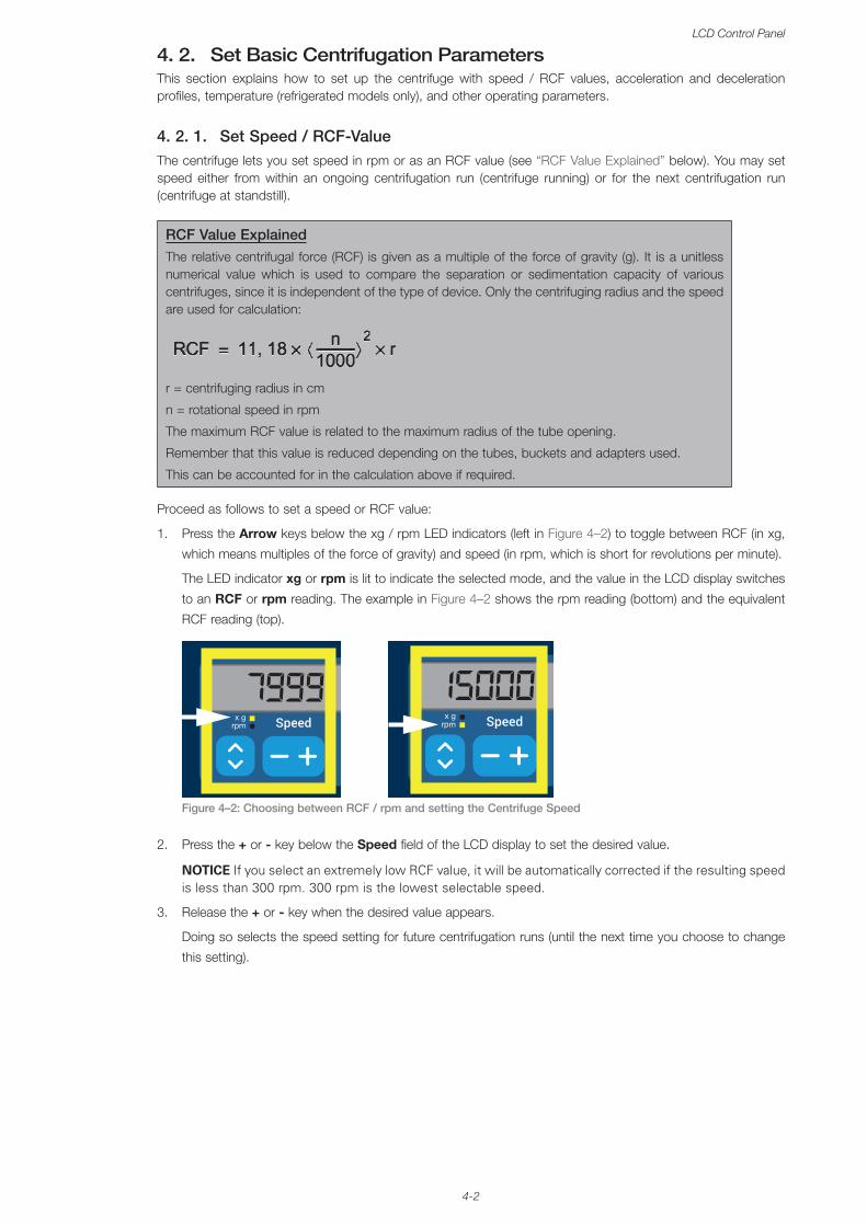
4-2
LCD Control Panel
4. 2. Set Basic Centrifugation ParametersThis section explains how to set up the centrifuge with speed / RCF values, acceleration and deceleration profiles, temperature (refrigerated models only), and other operating parameters.
4. 2. 1. Set Speed / RCF-ValueThe centrifuge lets you set speed in rpm or as an RCF value (see “RCF Value Explained” below). You may set speed either from within an ongoing centrifugation run (centrifuge running) or for the next centrifugation run (centrifuge at standstill).
RCF Value ExplainedThe relative centrifugal force (RCF) is given as a multiple of the force of gravity (g). It is a unitless numerical value which is used to compare the separation or sedimentation capacity of various centrifuges, since it is independent of the type of device. Only the centrifuging radius and the speed are used for calculation:
r = centrifuging radius in cm
n = rotational speed in rpm
The maximum RCF value is related to the maximum radius of the tube opening.
Remember that this value is reduced depending on the tubes, buckets and adapters used.
This can be accounted for in the calculation above if required.
Proceed as follows to set a speed or RCF value:
1. Press the Arrow keys below the xg / rpm LED indicators (left in Figure 4–2) to toggle between RCF (in xg,
which means multiples of the force of gravity) and speed (in rpm, which is short for revolutions per minute).
The LED indicator xg or rpm is lit to indicate the selected mode, and the value in the LCD display switches
to an RCF or rpm reading. The example in Figure 4–2 shows the rpm reading (bottom) and the equivalent
RCF reading (top).
Figure 4–2:
150007999
Choosing between RCF / rpm and setting the Centrifuge Speed
2. Press the + or - key below the Speed field of the LCD display to set the desired value.
NOTICE If you select an extremely low RCF value, it will be automatically corrected if the resulting speed is less than 300 rpm. 300 rpm is the lowest selectable speed.
3. Release the + or - key when the desired value appears.
Doing so selects the speed setting for future centrifugation runs (until the next time you choose to change
this setting).
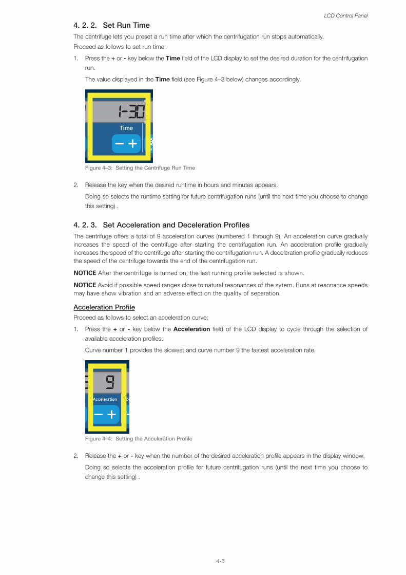
4-3
LCD Control Panel
4. 2. 2. Set Run TimeThe centrifuge lets you preset a run time after which the centrifugation run stops automatically.
Proceed as follows to set run time:
1. Press the + or - key below the Time field of the LCD display to set the desired duration for the centrifugation
run.
The value displayed in the Time field (see Figure 4–3 below) changes accordingly.
Figure 4–3:
15000 1:30 -5
Setting the Centrifuge Run Time
2. Release the key when the desired runtime in hours and minutes appears.
Doing so selects the runtime setting for future centrifugation runs (until the next time you choose to change
this setting) .
4. 2. 3. Set Acceleration and Deceleration ProfilesThe centrifuge offers a total of 9 acceleration curves (numbered 1 through 9). An acceleration curve gradually increases the speed of the centrifuge after starting the centrifugation run. An acceleration profile gradually increases the speed of the centrifuge after starting the centrifugation run. A deceleration profile gradually reduces the speed of the centrifuge towards the end of the centrifugation run.
NOTICE After the centrifuge is turned on, the last running profile selected is shown.
NOTICE Avoid if possible speed ranges close to natural resonances of the sytem. Runs at resonance speeds may have show vibration and an adverse effect on the quality of separation.
Acceleration ProfileProceed as follows to select an acceleration curve:
1. Press the + or - key below the Acceleration field of the LCD display to cycle through the selection of
available acceleration profiles.
Curve number 1 provides the slowest and curve number 9 the fastest acceleration rate.
Figure 4–4:
18 9
Setting the Acceleration Profile
2. Release the + or - key when the number of the desired acceleration profile appears in the display window.
Doing so selects the acceleration profile for future centrifugation runs (until the next time you choose to
change this setting) .
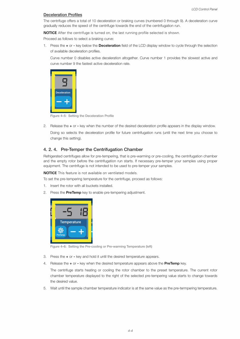
4-4
LCD Control Panel
Deceleration ProfilesThe centrifuge offers a total of 10 deceleration or braking curves (numbered 0 through 9). A deceleration curve gradually reduces the speed of the centrifuge towards the end of the centrifugation run.
NOTICE After the centrifuge is turned on, the last running profile selected is shown.
Proceed as follows to select a braking curve:
1. Press the + or - key below the Deceleration field of the LCD display window to cycle through the selection
of available deceleration profiles.
Curve number 0 disables active deceleration altogether. Curve number 1 provides the slowest active and
curve number 9 the fastest active deceleration rate.
Figure 4–5:
9 9
Setting the Deceleration Profile
2. Release the + or - key when the number of the desired deceleration profile appears in the display window.
Doing so selects the deceleration profile for future centrifugation runs (until the next time you choose to
change this setting).
4. 2. 4. Pre-Temper the Centrifugation ChamberRefrigerated centrifuges allow for pre-tempering, that is pre-warming or pre-cooling, the centrifugation chamber and the empty rotor before the centrifugation run starts. If necessary pre-temper your samples using proper equipment. The centrifuge is not intended to be used to pre-temper your samples.
NOTICE This feature is not available on ventilated models.
To set the pre-tempering temperature for the centrifuge, proceed as follows:
1. Insert the rotor with all buckets installed.
2. Press the PreTemp key to enable pre-tempering adjustment.
Figure 4–6:
1:30 18 -5
Setting the Pre-cooling or Pre-warming Temperature (left)
3. Press the + or - key and hold it until the desired temperature appears.
4. Release the + or - key when the desired temperature appears above the PreTemp key.
The centrifuge starts heating or cooling the rotor chamber to the preset temperature. The current rotor
chamber temperature displayed to the right of the selected pre-tempering value starts to change towards
the desired value.
5. Wait until the sample chamber temperature indicator is at the same value as the pre-termpering temperature.
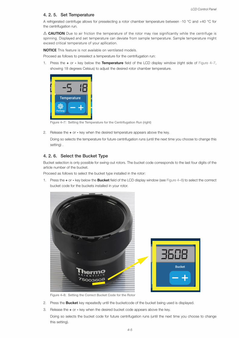
4-5
LCD Control Panel
4. 2. 5. Set TemperatureA refrigerated centrifuge allows for preselecting a rotor chamber temperature between -10 °C and +40 °C for the centrifugation run.
A CAUTION Due to air friction the temperature of the rotor may rise significantly while the centrifuge is spinning. Displayed and set temperature can deviate from sample temperature. Sample temperature might exceed critical temperature of your apllication.
NOTICE This feature is not available on ventilated models.
Proceed as follows to preselect a temperature for the centrifugation run:
1. Press the + or - key below the Temperature field of the LCD display window (right side of Figure 4–7,
showing 18 degrees Celsius) to adjust the desired rotor chamber temperature.
Figure 4–7:
1:30 18 -5
Setting the Temperature for the Centrifugation Run (right)
2. Release the + or - key when the desired temperature appears above the key.
Doing so selects the temperature for future centrifugation runs (until the next time you choose to change this
setting) .
4. 2. 6. Select the Bucket TypeBucket selection is only possible for swing-out rotors. The bucket code corresponds to the last four digits of the article number of the bucket.
Proceed as follows to select the bucket type installed in the rotor:
1. Press the + or - key below the Bucket field of the LCD display window (see Figure 4–8) to select the corrrect
bucket code for the buckets installed in your rotor.
Figure 4–8:
9 3608
Setting the Correct Bucket Code for the Rotor
2. Press the Bucket key repeatedly until the bucketcode of the bucket being used is displayed.
3. Release the + or - key when the desired bucket code appears above the key.
Doing so selects the bucket code for future centrifugation runs (until the next time you choose to change
this setting).
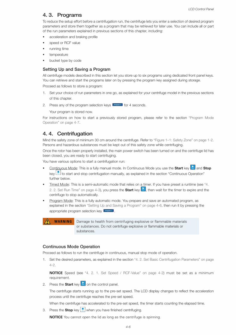
4-6
LCD Control Panel
4. 3. ProgramsTo reduce the setup effort before a centrifugation run, the centrifuge lets you enter a selection of desired program parameters and store them together as a program that may be retrieved for later use. You can include all or part of the run parameters explained in previous sections of this chapter, including:
� acceleration and braking profile
� speed or RCF value
� running time
� temperature
� bucket type by code
Setting Up and Saving a ProgramAll centrifuge models described in this section let you store up to six programs using dedicated front panel keys. You can retrieve and start the programs later on by pressing the program key assigned during storage.
Proceed as follows to store a program:
1. Set your choice of run parameters in one go, as explained for your centrifuge model in the previous sections
of this chapter.
2. Press any of the program selection keys Program 1 for 4 seconds.
Your program is stored now.
For instructions on how to start a previously stored program, please refer to the section “Program Mode Operation” on page 4-7.
4. 4. CentrifugationMind the safety zone of minimum 30 cm around the centrifuge. Refer to “Figure 1–1: Safety Zone” on page 1-2. Persons and hazardous substances must be kept out of this safety zone while centrifuging.
Once the rotor has been properly installed, the main power switch has been turned on and the centrifuge lid has been closed, you are ready to start centrifuging.
You have various options to start a centrifugation run:
� Continuous Mode: This is a fully manual mode. In Continuous Mode you use the Start key Start and Stop
key Stop to start and stop centrifugation manually, as explained in the section “Continuous Operation” further below.
� Timed Mode: This is a semi-automatic mode that relies on a timer. If you have preset a runtime (see “4.
2. 2. Set Run Time” on page 4-3), you press the Start key Start , then wait for the timer to expire and the centrifuge to stop automatically.
� Program Mode: This is a fully automatic mode. You prepare and save an automated program, as explained in the section “Setting Up and Saving a Program” on page 4-6, then run it by pressing the
appropriate program selection key Program 1 .
WARNING Damage to health from centrifuging explosive or flammable materials or substances. Do not centrifuge explosive or flammable materials or substances.
Continuous Mode OperationProceed as follows to run the centrifuge in continuous, manual stop mode of operation.
1. Set the desired parameters, as explained in the section “4. 2. Set Basic Centrifugation Parameters” on page
4-2.
NOTICE Speed (see “4. 2. 1. Set Speed / RCF-Value” on page 4-2) must be set as a minimum requirement.
2. Press the Start key Start on the control panel.
The centrifuge starts running up to the pre-set speed. The LCD display changes to reflect the acceleration
process until the centrifuge reaches the pre-set speed.
When the centrifuge has accelerated to the pre-set speed, the timer starts counting the elapsed time.
3. Press the Stop key Stop when you have finished centrifuging.
NOTICE You cannot open the lid as long as the centrifuge is spinning.
4-7
LCD Control Panel
Timed Mode OperationProceed as follows to run the centrifuge in timed mode of operation.
1. Set the desired parameters, as explained in the section “4. 2. Set Basic Centrifugation Parameters” on page
4-2.
NOTICE Speed (see “4. 2. 1. Set Speed / RCF-Value” on page 4-2) and runtime (see “4. 2. 2. Set Run Time” on page 4-3) must be set as a minimum requirement.
2. Press the Start key Start on the control panel.
The centrifuge starts running and the LCD display changes to indicate the correct speed.
When the centrifuge has accelerated to the pre-set speed, the timer starts counting the remaining time.
3. When the remaining time has elapsed, the centrifuge will stop automatically.
NOTICE You cannot open the lid as long as the centrifuge is spinning.
Program Mode OperationProceed as follows to start a previously stored program.
1. Press any of the program selection keys Program 1 to select a program.
NOTICE There is no need to set any parameters. All settings are included in the program.
2. Press the Start key Start to start the centrifugation run with the selected program’s setttings.
The centrifuge starts running up to the pre-set speed.
The LCD display changes to reflect the acceleration process until the centrifuge reaches the pre-set speed.
When the centrifuge has accelerated to the pre-set speed, the timer starts counting the remaining time.
3. When the remaining time has elapsed, the centrifuge will stop automatically.
NOTICE You cannot open the lid as long as the centrifuge is spinning.
Handling Error MessagesError messages may occur when you try to start the centrifuge. Frequent root causes include the following:
� Set speed exceeds admissible speed for rotor
� Imbalanced load
� Unapproved rotor found by rotor detection
A detailed list of error messages and troubleshooting instructions appear in the section “Troubleshooting by Guide” on page 6-2.
4. 5. Stop an Ongoing Centrifugation RunYou can stop the centrifuge at any time by pressing the Stop key Stop on the control panel.
Proceed as follows to stop an ongoing centrifugation run:
1. Press the Stop key Stop on the control panel.
2. Wait for the speed drop to zero.
The message END appears in the LCD display.
You can now open the lid and remove the centrifuged material, as explained in “How to Install and Remove
a Rotor” on page 2-3.

4-8
LCD Control Panel
4. 6. System MenuTo enter the system menu hold down any of the keys when powering on the centiruge.
Use the + and - keys below Speed in order to navigate through the system menu.
Use the + and - keys below Bucket in order to navigate within the system menu points.
Within the system menu you can change the settings of the centrifuge. Following settings are available:
1. Language – following languages are supported: English, German, French, Spanish, Italian, Dutch, Russian.
2. End of run beep – select YES if the centrifuge shall make beep after the run. Otherwise select NO.
3. Keypad beep – select YES if the centrifuge shall make beep when pressing any key. Otherwise select NO.
4. LCD powersave – select YES if the centrifuge shall enter a powersave mode after the run. Otherwise select
NO.
5. Auto lid open – select YES if the centrifuge shall open after the run. Otherwise select NO.
6. Software ID – the current software version is shown here.
7. Cycle count – the current numbers of cycles are shown here.
5-1
Maintenance and Care
5. Maintenance and Care
5. 1. Cleaning IntervalsFor the sake of personal, environmental, and material protection, you must clean and if necessary disinfect the centrifuge and its accessories on a regular basis.
5. 2. Basics � Use warm water with a neutral detergent that is suitable for use with the materials. If in doubt contact
the manufacturer of the cleaning agent. � Use a soft cloth for cleaning. � Never use caustic cleaning agents such as soap suds, phosphoric acid, bleaching solutions or
scrubbing powder. � Remove rotor and clean centrifugation chamber with a small amount of cleaning agent on a clean
cloth. � Use a soft brush without metal bristles to remove stubborn residue. � Afterwards rinse with a small amount of distilled water and remove any remains with absorbent
towels. � Use only cleaning and disinfecting agents with a pH of 6-8.
CAUTION Not rated procedures or agents could deteriorate the materials of the centrifuge and lead to malfunction. Refrain from using any other cleaning or decontamination procedure, if you are not entirely sure that the intended procedure is safe for the equipment. Use only cleaning agents that will not damage the equipment. In doubt contact the manufacturer of the cleaning agent. If still in doubt, contact Thermo Fisher Scientific.
5. 2. 1. Rotor and Accessories InspectionAfter thoroughly cleaning the rotors, they must be inspected for damage, wear and corrosion.
The cycle limits of the rotors and buckets are stated on some rotors and buckets and in the technical data section of each rotor (“Rotor Specifications” on page B-1).
NOTICE Usage beyond these limits might lead to rotor failure, sample loss and damage to the centrifuge.
CAUTION Do not run any rotor or accessories with sign of damage. Ensure that the rotor, buckets and accessories are within their expected maximum number of cycles. It is recommend that you have rotors and accessories inspected yearly as part of your routine service to ensure safety.
Metal PartsMake sure that the protective coating is complete. It can be removed through wear and chemical attack and can lead to unseen corrosions. In case of corrosion, such as rust or white / metalic pitting, the rotor or accessories must be removed from service immediately. Particular attention should be paid to the bottom of buckets on swing out rotors and tube cavities on fixed angle rotors.
Slide Coated Rotors
Rotor crosses are provided with an anti-friction and corrosion resistant finish.
The following procedure is for rotor crosses and rotor trunnion bolts:
� Regular cleaning of contact area between the rotor and buckets (rotor cross trunnions and bucket grooves) is recommended with a mild detergent (every 300-500 cycles).
� The rotor cross is coated with a special advanced lubricating and protective coating, therefore no grease is necessary.
� Contaminating particles (dirt, dust or debris) in the rotor cross and bucket grooves may lead to imbalance and cleaning will be required.
� The lubricating coating may, over extended periods or under heavy loads, become worn. If this occurs a small amount of greasing of the rotor cross trunnions will be required with bolt grease (75003786).
5-2
Maintenance and Care
Plastic PartsCheck for signs of plastic crazing, fading, bruising or cracking. In case of damage the inspected item must be removed from service immediately.
O-RingsMake sure that O-rings are still smooth, not brittle nor otherwise damaged. Some O-rings are not autoclavable.
Replace brittle or damaged O-rings immediately. Refer to “Rotor Specifications” on page B-1 for details on O-rings as spare part.
5. 2. 2. Cycles of Rotors and BucketsYou have to count the cycles of the rotors and buckets using your own method. The centrifuge can not detect the change or replacement of rotors of the same type or of buckets of the same type.
The lifetime of a rotor and buckets depends on the amount of physical load. Do not use rotors and buckets that exceed the maximum number of cycles.
The maximum number of cycles for rotors and buckets is given in the chapter “Rotor Specifications” on page B-1. The maximum number of cycles for buckets is marked on the buckets themselves.
Fiberlite rotors are not limited in cycles, but have a limited lifetime of 15 years.
Centrifuges with a GUIThe centrifuge counts cycles for a rotor type or a bucket type. You have to count the cycles of the rotors and buckets using your own method. The centrifuge can not detect the change or replacement of rotors of the same type or of buckets of the same type.
You can check the number of cycles for a rotor type on the user interface of the centrifuge. The rotor log saves the information of the used rotor types and bucket types. Refer to “Rotor Log” on page 3-47 for detailed information and to “Status” on page 3-14 for a quick information.
Centrifuges with a LCD Control PanelThe centrifuge does not count cycles for a rotor type or a bucket type. You have to count the cycles of the rotors and buckets using your own method.
5. 3. CleaningClean as follows:
1. Clean rotor, buckets and accessories outside of the centrifugation chamber.
2. Separate rotor, buckets, lids, adapters, tubes and O-rings to allow thorough cleaning.
3. Rinse rotor and all accessories with warm water and a neutral detergent that is suitable for use with the
materials. If in doubt contact the manufacturer of the cleaning agent. Clean away the grease from the rotor
trunnions (pivot point for swinging buckets).
4. Use a soft brush without metal bristles to remove stubborn residue.
5. Rinse rotor and all accessories with distilled water.
6. Place the rotors on a plastic grate with their cavities pointing down, to enable the cavities to fully drain and
dry.
7. Dry all of the rotors and accessories after cleaning with a cloth or in a warm air cabinet at a maximum
temperature of 50 °C. If drying boxes are used, the temperature must never exceed 50 °C. Higher
temperatures could damage the material and shorten the lifetime of the parts.
8. Inspect the rotor and accessories for signs of damages (“Rotor and Accessories Inspection” on page 5-1).
9. After cleaning, treat the entire surface of aluminum parts including the cavities with corrosion protection oil
(70009824).
Treat the bolts of swing out rotors with bolt grease (75003786) if necessary.
CAUTION Before using any cleaning methods, users should check with the manufacturer of the cleaning agents that the proposed method will not damage the equipment.
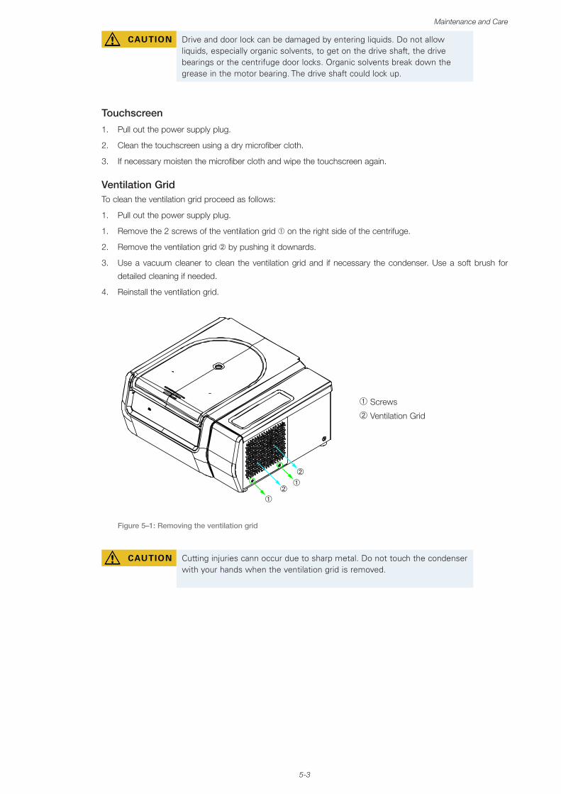
5-3
Maintenance and Care
CAUTION Drive and door lock can be damaged by entering liquids. Do not allow liquids, especially organic solvents, to get on the drive shaft, the drive bearings or the centrifuge door locks. Organic solvents break down the grease in the motor bearing. The drive shaft could lock up.
Touchscreen
1. Pull out the power supply plug.
2. Clean the touchscreen using a dry microfiber cloth.
3. If necessary moisten the microfiber cloth and wipe the touchscreen again.
Ventilation GridTo clean the ventilation grid proceed as follows:
1. Pull out the power supply plug.
1. Remove the 2 screws of the ventilation grid ➀ on the right side of the centrifuge.
2. Remove the ventilation grid ➁ by pushing it downards.
3. Use a vacuum cleaner to clean the ventilation grid and if necessary the condenser. Use a soft brush for
detailed cleaning if needed.
4. Reinstall the ventilation grid.
➀
➀
➁
➁
➀ Screws
➁ Ventilation Grid
Figure 5–1: Removing the ventilation grid
CAUTION Cutting injuries cann occur due to sharp metal. Do not touch the condenser with your hands when the ventilation grid is removed.
5-4
Maintenance and Care
5. 4. DisinfectionYou are responsible that the level of disinfection is achieved according to your requirements.
After disinfection:
1. Rinse the centrifuge and all affected accessories with water.
2. Allow to fully drain and dry.
3. After disinfecting, treat the entire surface of aluminum parts including the cavities with corrosion protection
oil (70009824).
Treat the bolts of swing out rotors with bolt grease (75003786) if necessary.
WARNING Do not touch infected parts. Hazardous infection is possible when touching the contaminated rotor and centrifuge parts. Infectious material can get into the centrifuge when a tube breaks or as a result of spills. In case of contamination, make sure that no one is put at risk. Disinfect the affected parts immediately.
CAUTION Equipment can be damaged by inappropriate disinfection methods or agents. Make sure that the disinfection agent or the method will not damage the equipment. In doubt contact the manufacturer of the disinfection agent. Observe the safety precautions and handling instructions for the disinfection agents used.
5. 5. DecontaminationYou are responsible that the level of decontamination is achieved according to your requirements.
After decontamination:
1. Rinse the centrifuge and all affected accessories with water.
2. Allow to fully drain and dry.
3. After decontaminating, treat the entire surface of aluminum parts including the cavities with corrosion
protection oil (70009824).
Treat the bolts of swing out rotors with bolt grease (75003786) if necessary.
WARNING Do not touch contaminated parts. Exposure to radiation is possible when touching the contaminated rotor and centrifuge parts. Contaminated material can get into the centrifuge when a tube breaks or as a result of spills. In case of contamination, make sure that no one is put at risk. Decontaminate the affected parts immediately.
CAUTION Equipment can be damaged by inappropriate decontamination methods or agents. Make sure that the decontamination agent or the method will not damage the equipment. In doubt contact the manufacturer of the decontamination agent. Observe the safety precautions and handling instructions for the decontamination agents used.
5-5
Maintenance and Care
5. 6. AutoclavingAlways disassemble all parts before autoclaving, e.g. lids need to be removed before autoclaving a bucket or rotor.
If not stated otherwise on the parts themselves, all parts can be autoclaved at 121 °C for 20 min. Refer to “Rotor Specifications” on page B-1 for details on rotors.
Make sure that the necessary sterility is achieved according to your requirements.
After autoclaving, treat the entire surface of aluminum parts including the cavities with corrosion protection oil (70009824).
Treat the bolts of swing out rotors with bolt grease (75003786) if necessary.
CAUTION Never exceed the permitted temperature and duration when autoclaving.
NOTICE No chemical additives are permitted in the steam.
5. 7. Maintenance
LifetimeThe centrifuge is specified for a lifetime of 10 years. Decommissioning the centrifuge is suggested when this limit is reached.
The lifetime of a rotor and buckets depends on the amount of physical load. Do not use rotors and buckets that exceed the maximum number of cycles. The maximum number of cycles for rotors and buckets is given in the chapter “Rotor Specifications” on page B-1. The maximum number of cycles for buckets is marked on the buckets themselves. Fiberlite rotors are not limited in cycles, but have a limited lifetime of 15 years.
Preventive MaintenanceIn order to keep this product able to perform the intended applications reliably and safely, ongoing preventive maintenance is necessary in accordance with the following recommended schedule:
� The anti-vibration mounts (20038955) and the motor cover (20058551) need to be replaced every 3 years.
� The gas spring (50154683) and the particle deflection seal (50154683) need to be checked annually and replaced if necessary. Refer to Figure 2–1 on page 2-1
� For rotors and buckets mind the information in “Rotor and Accessories Inspection” on page 5-1.
CAUTION Usage beyond these limits might affect the safety of the overall system.
NOTICEIn the worst case the centrifuge, the used accessories and the samples can be damaged.
NOTICEMaintenance activities must be performed by Thermo Fisher Scientific authorized service technicians only.
5-6
Maintenance and Care
ServiceThermo Fisher Scientific recommends having the centrifuge and accessories serviced once a year by an authorized service technician. The service technician checks the following:
� electrical equipment and connections
� suitability of set-up site
� centrifuge door lock and safety system
� rotor
� fixation of rotor and drive shaft of the centrifuge
� rubber gasket
� protective casing
� anti-vibration mounts
Before service, centrifuge and rotors should be thoroughly cleaned and decontaminated to ensure full and safe inspection can be completed.
Thermo Fisher Scientific offers inspection and service contracts for this work. Any necessary repairs are performed for free during the warranty period and afterwards for a charge. That is only valid if the centrifuge has only been maintained by an authorized Thermo Fisher Scientific service technician.
A validation of the centrifuge is recommended and can be ordered from customer service.
5. 8. ShippingBefore shipping the centrifuge:
� The centrifuge must be clean and decontaminated.
� You must confirm the decontamination with a decontamination certificate.
WARNING Before shipping the centrifuge and accessories you must clean and, if necessary, disinfect or decontaminate the full system. If you are not sure, consult with Thermo Fisher Scientific customer service.
5. 9. Storage � Before storing the centrifuge and the accessories it must be clean and if necessary disinfected and
decontaminated.
Centrifuge, rotors, buckets and accessories have to be fully dry before storage.
� Keep the centrifuge in a clean, dry and dust-free location.
� Do not store the centrifuge in direct sunlight.
WARNING When you remove the centrifuge and accessories from use, clean and if necessary disinfect or decontaminate the full system. If you are not sure speak to the Thermo Fisher Scientific customer service.
5. 10. DisposalFor the disposal of the centrifuge mind the regulations in your country. Contact the Thermo Fisher Scientific Customer Service for the disposal of the centrifuge. For contact information check the backpage of this manual or visit www.thermofisher.com/centrifuge
For the countries of the European Union the disposal is regulated by the European Union’s Waste Electrical & Electronic Equipment (WEEE) Directive 2012/19/EC.
Mind the information on transport and shipping (“Shipping” on page 5-6 and “Transporting” on page 1-2).
WARNING When removing the centrifuge and accessories from use for disposal you have to clean and if necessary disinfect or decontaminate the entire system. In doubt contact the Thermo Fisher Scientific customer service.
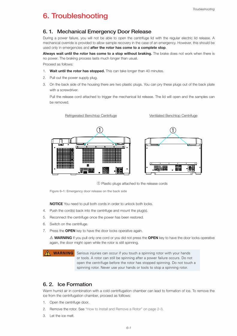
6-1
Troubleshooting
6. Troubleshooting
6. 1. Mechanical Emergency Door ReleaseDuring a power failure, you will not be able to open the centrifuge lid with the regular electric lid release. A mechanical override is provided to allow sample recovery in the case of an emergency. However, this should be used only in emergencies and after the rotor has come to a complete stop.
Always wait until the rotor has come to a stop without braking. The brake does not work when there is no power. The braking process lasts much longer than usual.
Proceed as follows:
1. Wait until the rotor has stopped. This can take longer than 40 minutes.
2. Pull out the power supply plug.
3. On the back side of the housing there are two plastic plugs. You can pry these plugs out of the back plate
with a screwdriver.
Pull the release cord attached to trigger the mechanical lid release. The lid will open and the samples can
be removed.
Refrigerated Benchtop Centrifuge Ventilated Benchtop Centrifuge
➀ ➀
➀ Plastic plugs attached to the release cords
Figure 6–1: Emergency door release on the back side
NOTICE You need to pull both cords in order to unlock both locks.
4. Push the cord(s) back into the centrifuge and mount the plug(s).
5. Reconnect the centrifuge once the power has been restored.
6. Switch on the centrifuge.
7. Press the OPEN key to have the door locks operative again.
A WARNING If you pull only one cord or you did not press the OPEN key to have the door locks operative again, the door might open while the rotor is still spinning.
WARNING Serious injuries can occur if you touch a spinning rotor with your hands or tools. A rotor can still be spinning after a power failure occurs. Do not open the centrifuge before the rotor has stopped spinning. Do not touch a spinning rotor. Never use your hands or tools to stop a spinning rotor.
6. 2. Ice FormationWarm humid air in combination with a cold centrifugation chamber can lead to formation of ice. To remove the ice from the centrifugation chamber, proceed as folllows:
1. Open the centrifuge door.
2. Remove the rotor. See “How to Install and Remove a Rotor” on page 2-3.
3. Let the ice melt.
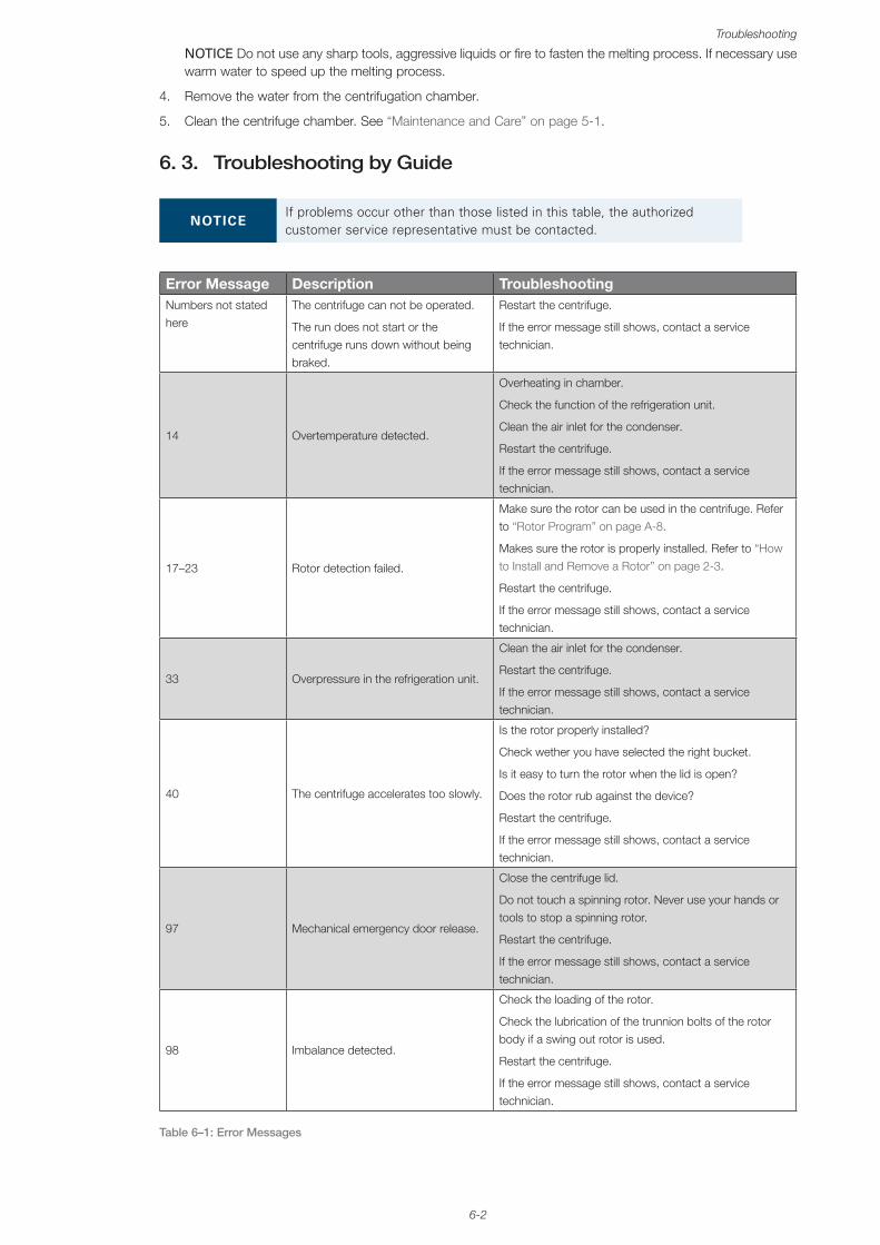
6-2
Troubleshooting
NOTICE Do not use any sharp tools, aggressive liquids or fire to fasten the melting process. If necessary use warm water to speed up the melting process.
4. Remove the water from the centrifugation chamber.
5. Clean the centrifuge chamber. See “Maintenance and Care” on page 5-1.
6. 3. Troubleshooting by Guide
NOTICEIf problems occur other than those listed in this table, the authorized customer service representative must be contacted.
Error Message Description TroubleshootingNumbers not stated here
The centrifuge can not be operated.
The run does not start or the centrifuge runs down without being braked.
Restart the centrifuge.
If the error message still shows, contact a service technician.
14 Overtemperature detected.
Overheating in chamber.
Check the function of the refrigeration unit.
Clean the air inlet for the condenser.
Restart the centrifuge.
If the error message still shows, contact a service technician.
17–23 Rotor detection failed.
Make sure the rotor can be used in the centrifuge. Refer to “Rotor Program” on page A-8.
Makes sure the rotor is properly installed. Refer to “How to Install and Remove a Rotor” on page 2-3.
Restart the centrifuge.
If the error message still shows, contact a service technician.
33 Overpressure in the refrigeration unit.
Clean the air inlet for the condenser.
Restart the centrifuge.
If the error message still shows, contact a service technician.
40 The centrifuge accelerates too slowly.
Is the rotor properly installed?
Check wether you have selected the right bucket.
Is it easy to turn the rotor when the lid is open?
Does the rotor rub against the device?
Restart the centrifuge.
If the error message still shows, contact a service technician.
97 Mechanical emergency door release.
Close the centrifuge lid.
Do not touch a spinning rotor. Never use your hands or tools to stop a spinning rotor.
Restart the centrifuge.
If the error message still shows, contact a service technician.
98 Imbalance detected.
Check the loading of the rotor.
Check the lubrication of the trunnion bolts of the rotor body if a swing out rotor is used.
Restart the centrifuge.
If the error message still shows, contact a service technician.
Table 6–1: Error Messages

6-3
Troubleshooting
6. 4. Information for the Customer ServiceIf you need to contact customer service, please provide the order no. and the serial no. of your device. This information can be found on the type plate.
To identify the software version on a centrifuge with a LCD control panel, proceed as follows:
1. Hold down any of the keys and then switch on the centrifuge.
You enter the system menu.
2. Press the START key.
3. Press and hold the ENTER key, until the following message is displayed:
Software ID: xxxxxxx
To identify the software version on a centrifuge with a GUI, proceed as follows:
Press the Files and Info button on the navigation bar. Product version information is displayed.
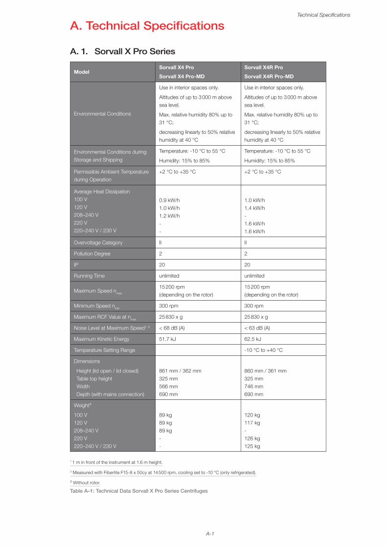
A-1
Technical Specifications
A. Technical Specifications
A. 1. Sorvall X Pro Series
ModelSorvall X4 Pro
Sorvall X4 Pro-MD
Sorvall X4R Pro
Sorvall X4R Pro-MD
Environmental Conditions
Use in interior spaces only.
Altitudes of up to 3 000 m above sea level.
Max. relative humidity 80% up to 31 °C;
decreasing linearly to 50% relative humidity at 40 °C
Use in interior spaces only.
Altitudes of up to 3 000 m above sea level.
Max. relative humidity 80% up to 31 °C;
decreasing linearly to 50% relative humidity at 40 °C
Environmental Conditions during Storage and Shipping
Temperature: -10 °C to 55 °C
Humidity: 15% to 85%
Temperature: -10 °C to 55 °C
Humidity: 15% to 85%
Permissible Ambient Temperature during Operation
+2 °C to +35 °C +2 °C to +35 °C
Average Heat Dissipation 100 V 120 V 208–240 V 220 V 220–240 V / 230 V
0.9 kW/h 1.0 kW/h 1.2 kW/h - -
1.0 kW/h 1.4 kW/h - 1.6 kW/h 1.6 kW/h
Overvoltage Category II II
Pollution Degree 2 2
IP 20 20
Running Time unlimited unlimited
Maximum Speed nmax
15 200 rpm (depending on the rotor)
15 200 rpm (depending on the rotor)
Minimum Speed nmin 300 rpm 300 rpm
Maximum RCF Value at nmax 25 830 x g 25 830 x g
Noise Level at Maximum Speed1, 2 < 68 dB (A) < 63 dB (A)
Maximum Kinetic Energy 51.7 kJ 62.5 kJ
Temperature Setting Range -10 °C to +40 °C
Dimensions
Height (lid open / lid closed) Table top height Width Depth (with mains connection)
861 mm / 362 mm 325 mm 566 mm 690 mm
860 mm / 361 mm 325 mm 746 mm 690 mm
Weight³
100 V 120 V 208–240 V 220 V 220–240 V / 230 V
89 kg 89 kg 89 kg - -
120 kg 117 kg - 126 kg 125 kg
1 1 m in front of the instrument at 1.6 m height.
2 Measured with Fiberlite F15-8 x 50cy at 14 500 rpm, cooling set to -10 °C (only refrigerated).
³ Without rotor.
Table A–1: Technical Data Sorvall X Pro Series Centrifuges
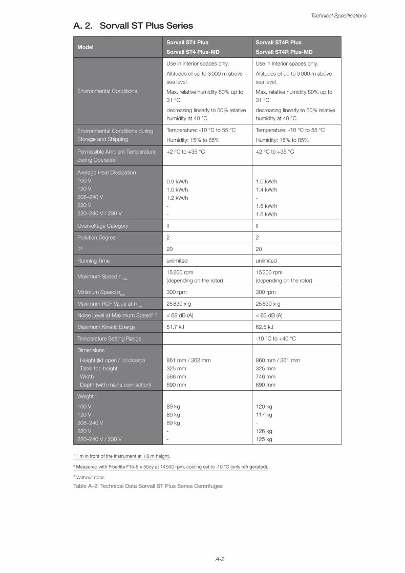
A-2
Technical Specifications
A. 2. Sorvall ST Plus Series
ModelSorvall ST4 Plus
Sorvall ST4 Plus-MD
Sorvall ST4R Plus
Sorvall ST4R Plus-MD
Environmental Conditions
Use in interior spaces only.
Altitudes of up to 3 000 m above sea level.
Max. relative humidity 80% up to 31 °C;
decreasing linearly to 50% relative humidity at 40 °C
Use in interior spaces only.
Altitudes of up to 3 000 m above sea level.
Max. relative humidity 80% up to 31 °C;
decreasing linearly to 50% relative humidity at 40 °C
Environmental Conditions during Storage and Shipping
Temperature: -10 °C to 55 °C
Humidity: 15% to 85%
Temperature: -10 °C to 55 °C
Humidity: 15% to 85%
Permissible Ambient Temperature during Operation
+2 °C to +35 °C +2 °C to +35 °C
Average Heat Dissipation 100 V 120 V 208–240 V 220 V 220–240 V / 230 V
0.9 kW/h 1.0 kW/h 1.2 kW/h - -
1.0 kW/h 1.4 kW/h - 1.6 kW/h 1.6 kW/h
Overvoltage Category II II
Pollution Degree 2 2
IP 20 20
Running Time unlimited unlimited
Maximum Speed nmax
15 200 rpm (depending on the rotor)
15 200 rpm (depending on the rotor)
Minimum Speed nmin 300 rpm 300 rpm
Maximum RCF Value at nmax 25 830 x g 25 830 x g
Noise Level at Maximum Speed1, 2 < 68 dB (A) < 63 dB (A)
Maximum Kinetic Energy 51.7 kJ 62.5 kJ
Temperature Setting Range -10 °C to +40 °C
Dimensions
Height (lid open / lid closed) Table top height Width Depth (with mains connection)
861 mm / 362 mm 325 mm 566 mm 690 mm
860 mm / 361 mm 325 mm 746 mm 690 mm
Weight³
100 V 120 V 208–240 V 220 V 220–240 V / 230 V
89 kg 89 kg 89 kg - -
120 kg 117 kg - 126 kg 125 kg
1 1 m in front of the instrument at 1.6 m height.
2 Measured with Fiberlite F15-8 x 50cy at 14 500 rpm, cooling set to -10 °C (only refrigerated).
³ Without rotor.
Table A–2: Technical Data Sorvall ST Plus Series Centrifuges
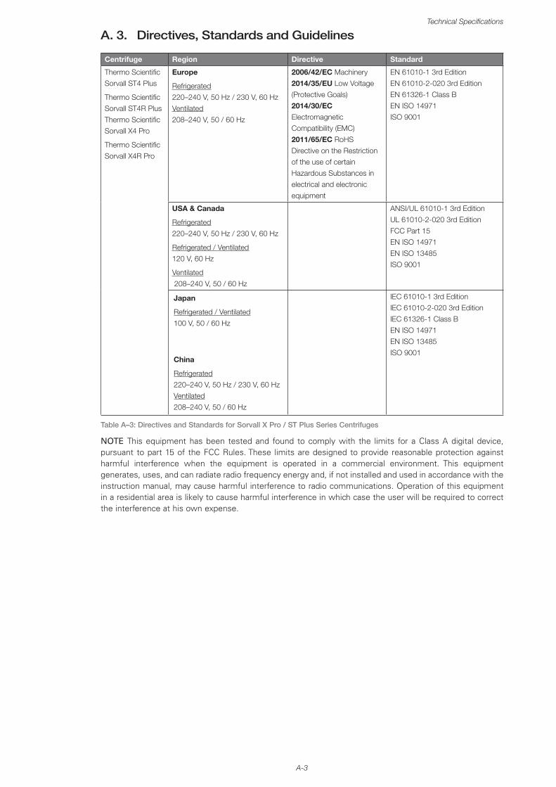
A-3
Technical Specifications
A. 3. Directives, Standards and Guidelines
Centrifuge Region Directive Standard
Thermo Scientific Sorvall ST4 Plus
Thermo Scientific Sorvall ST4R Plus Thermo Scientific Sorvall X4 Pro
Thermo Scientific Sorvall X4R Pro
Europe
Refrigerated 220–240 V, 50 Hz / 230 V, 60 Hz Ventilated 208–240 V, 50 / 60 Hz
2006/42/EC Machinery 2014/35/EU Low Voltage (Protective Goals) 2014/30/EC Electromagnetic Compatibility (EMC) 2011/65/EC RoHS Directive on the Restriction of the use of certain Hazardous Substances in electrical and electronic equipment
EN 61010-1 3rd Edition EN 61010-2-020 3rd Edition EN 61326-1 Class B EN ISO 14971 ISO 9001
USA & Canada
Refrigerated 220–240 V, 50 Hz / 230 V, 60 Hz
Refrigerated / Ventilated 120 V, 60 Hz
Ventilated 208–240 V, 50 / 60 Hz
ANSI/UL 61010-1 3rd Edition UL 61010-2-020 3rd Edition FCC Part 15 EN ISO 14971 EN ISO 13485 ISO 9001
Japan
Refrigerated / Ventilated 100 V, 50 / 60 Hz
China
Refrigerated 220–240 V, 50 Hz / 230 V, 60 Hz Ventilated 208–240 V, 50 / 60 Hz
IEC 61010-1 3rd Edition IEC 61010-2-020 3rd Edition IEC 61326-1 Class B EN ISO 14971 EN ISO 13485 ISO 9001
Table A–3: Directives and Standards for Sorvall X Pro / ST Plus Series Centrifuges
NOTE This equipment has been tested and found to comply with the limits for a Class A digital device, pursuant to part 15 of the FCC Rules. These limits are designed to provide reasonable protection against harmful interference when the equipment is operated in a commercial environment. This equipment generates, uses, and can radiate radio frequency energy and, if not installed and used in accordance with the instruction manual, may cause harmful interference to radio communications. Operation of this equipment in a residential area is likely to cause harmful interference in which case the user will be required to correct the interference at his own expense.
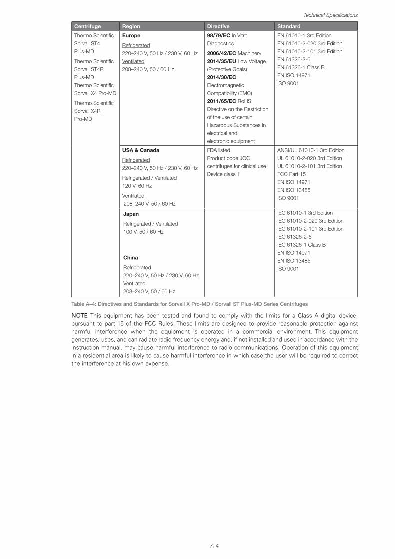
A-4
Technical Specifications
Centrifuge Region Directive Standard
Thermo Scientific Sorvall ST4 Plus-MD
Thermo Scientific Sorvall ST4R Plus-MD Thermo Scientific Sorvall X4 Pro-MD
Thermo Scientific Sorvall X4R Pro-MD
Europe
Refrigerated 220–240 V, 50 Hz / 230 V, 60 Hz Ventilated 208–240 V, 50 / 60 Hz
98/79/EC In Vitro Diagnostics
2006/42/EC Machinery 2014/35/EU Low Voltage (Protective Goals) 2014/30/EC Electromagnetic Compatibility (EMC) 2011/65/EC RoHS Directive on the Restriction of the use of certain Hazardous Substances in electrical and electronic equipment
EN 61010-1 3rd Edition EN 61010-2-020 3rd Edition EN 61010-2-101 3rd Edition EN 61326-2-6 EN 61326-1 Class B EN ISO 14971 ISO 9001
USA & Canada
Refrigerated 220–240 V, 50 Hz / 230 V, 60 Hz
Refrigerated / Ventilated 120 V, 60 Hz
Ventilated 208–240 V, 50 / 60 Hz
FDA listed Product code JQC centrifuges for clinical use Device class 1
ANSI/UL 61010-1 3rd Edition UL 61010-2-020 3rd Edition UL 61010-2-101 3rd Edition FCC Part 15 EN ISO 14971 EN ISO 13485 ISO 9001
Japan
Refrigerated / Ventilated 100 V, 50 / 60 Hz
China
Refrigerated 220–240 V, 50 Hz / 230 V, 60 Hz Ventilated 208–240 V, 50 / 60 Hz
IEC 61010-1 3rd Edition IEC 61010-2-020 3rd Edition IEC 61010-2-101 3rd Edition IEC 61326-2-6 IEC 61326-1 Class B EN ISO 14971 EN ISO 13485 ISO 9001
Table A–4: Directives and Standards for Sorvall X Pro-MD / Sorvall ST Plus-MD Series Centrifuges
NOTE This equipment has been tested and found to comply with the limits for a Class A digital device, pursuant to part 15 of the FCC Rules. These limits are designed to provide reasonable protection against harmful interference when the equipment is operated in a commercial environment. This equipment generates, uses, and can radiate radio frequency energy and, if not installed and used in accordance with the instruction manual, may cause harmful interference to radio communications. Operation of this equipment in a residential area is likely to cause harmful interference in which case the user will be required to correct the interference at his own expense.
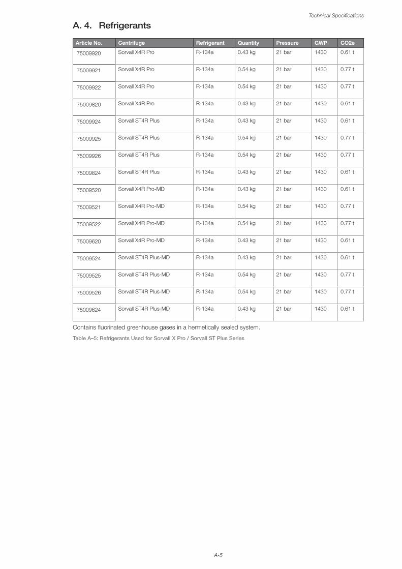
A-5
Technical Specifications
A. 4. Refrigerants
Article No. Centrifuge Refrigerant Quantity Pressure GWP CO2e
75009920 Sorvall X4R Pro R-134a 0.43 kg 21 bar 1430 0.61 t
75009921 Sorvall X4R Pro R-134a 0.54 kg 21 bar 1430 0.77 t
75009922 Sorvall X4R Pro R-134a 0.54 kg 21 bar 1430 0.77 t
75009820 Sorvall X4R Pro R-134a 0.43 kg 21 bar 1430 0.61 t
75009924 Sorvall ST4R Plus R-134a 0.43 kg 21 bar 1430 0.61 t
75009925 Sorvall ST4R Plus R-134a 0.54 kg 21 bar 1430 0.77 t
75009926 Sorvall ST4R Plus R-134a 0.54 kg 21 bar 1430 0.77 t
75009824 Sorvall ST4R Plus R-134a 0.43 kg 21 bar 1430 0.61 t
75009520 Sorvall X4R Pro-MD R-134a 0.43 kg 21 bar 1430 0.61 t
75009521 Sorvall X4R Pro-MD R-134a 0.54 kg 21 bar 1430 0.77 t
75009522 Sorvall X4R Pro-MD R-134a 0.54 kg 21 bar 1430 0.77 t
75009620 Sorvall X4R Pro-MD R-134a 0.43 kg 21 bar 1430 0.61 t
75009524 Sorvall ST4R Plus-MD R-134a 0.43 kg 21 bar 1430 0.61 t
75009525 Sorvall ST4R Plus-MD R-134a 0.54 kg 21 bar 1430 0.77 t
75009526 Sorvall ST4R Plus-MD R-134a 0.54 kg 21 bar 1430 0.77 t
75009624 Sorvall ST4R Plus-MD R-134a 0.43 kg 21 bar 1430 0.61 t
Contains fluorinated greenhouse gases in a hermetically sealed system.
Table A–5: Refrigerants Used for Sorvall X Pro / Sorvall ST Plus Series
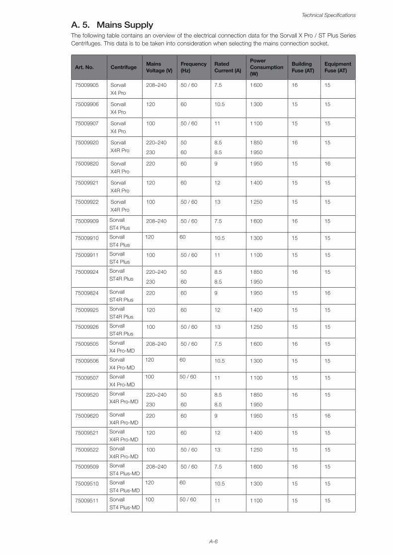
A-6
Technical Specifications
A. 5. Mains SupplyThe following table contains an overview of the electrical connection data for the Sorvall X Pro / ST Plus Series Centrifuges. This data is to be taken into consideration when selecting the mains connection socket.
Art. No. CentrifugeMains Voltage (V)
Frequency (Hz)
Rated Current (A)
Power Consumption (W)
Building Fuse (AT)
Equipment Fuse (AT)
75009905 Sorvall X4 Pro
208–240 50 / 60 7.5 1 600 16 15
75009906 Sorvall X4 Pro
120 60 10.5 1 300 15 15
75009907 Sorvall X4 Pro
100 50 / 60 11 1 100 15 15
75009920 Sorvall X4R Pro
220–240
230
50
60
8.5
8.5
1 850
1 950
16 15
75009820 Sorvall X4R Pro
220 60 9 1 950 15 16
75009921 Sorvall X4R Pro
120 60 12 1 400 15 15
75009922 Sorvall X4R Pro
100 50 / 60 13 1 250 15 15
75009909 Sorvall ST4 Plus
208–240 50 / 60 7.5 1 600 16 15
75009910 Sorvall ST4 Plus
120 60 10.5 1 300 15 15
75009911 Sorvall ST4 Plus
100 50 / 60 11 1 100 15 15
75009924 Sorvall ST4R Plus
220–240
230
50
60
8.5
8.5
1 850
1 950
16 15
75009824 Sorvall ST4R Plus
220 60 9 1 950 15 16
75009925 Sorvall ST4R Plus
120 60 12 1 400 15 15
75009926 Sorvall ST4R Plus
100 50 / 60 13 1 250 15 15
75009505 Sorvall X4 Pro-MD
208–240 50 / 60 7.5 1 600 16 15
75009506 Sorvall X4 Pro-MD
120 60 10.5 1 300 15 15
75009507 Sorvall X4 Pro-MD
100 50 / 60 11 1 100 15 15
75009520 Sorvall X4R Pro-MD
220–240
230
50
60
8.5
8.5
1 850
1 950
16 15
75009620 Sorvall X4R Pro-MD
220 60 9 1 950 15 16
75009521 Sorvall X4R Pro-MD
120 60 12 1 400 15 15
75009522 Sorvall X4R Pro-MD
100 50 / 60 13 1 250 15 15
75009509 Sorvall ST4 Plus-MD
208–240 50 / 60 7.5 1 600 16 15
75009510 Sorvall ST4 Plus-MD
120 60 10.5 1 300 15 15
75009511 Sorvall ST4 Plus-MD
100 50 / 60 11 1 100 15 15

A-7
Technical Specifications
Art. No. CentrifugeMains Voltage (V)
Frequency (Hz)
Rated Current (A)
Power Consumption (W)
Building Fuse (AT)
Equipment Fuse (AT)
75009524 Sorvall ST4R Plus-MD
220–240
230
50
60
8.5
8.5
1 850
1 950
16 15
75009624 Sorvall ST4R Plus-MD
220 60 9 1 950 15 16
75009525 Sorvall ST4R Plus-MD
120 60 12 1 400 15 15
75009526 Sorvall ST4R Plus-MD
100 50 / 60 13 1 250 15 15
Table A–6: Electrical Connection Data for Sorvall X Pro / ST Plus Series
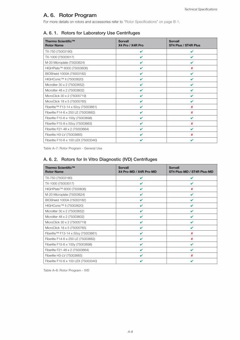
A-8
Technical Specifications
A. 6. Rotor ProgramFor more details on rotors and accessories refer to “Rotor Specifications” on page B-1.
A. 6. 1. Rotors for Laboratory Use Centrifuges
Thermo Scientific™ Rotor Name
Sorvall X4 Pro / X4R Pro
Sorvall ST4 Plus / ST4R Plus
TX-750 (75003180) ✔ ✔
TX-1000 (75003017) ✔ ✔
M-20 Microplate (75003624) ✔ ✔
HIGHPlate™ 6000 (75003606) ✔ ✘
BIOShield 1000A (75003182) ✔ ✔
HIGHConic™ II (75003620) ✔ ✔
Microliter 30 x 2 (75003652) ✔ ✔
Microliter 48 x 2 (75003602) ✔ ✔
MicroClick 30 x 2 (75005719) ✔ ✔
MicroClick 18 x 5 (75005765) ✔ ✔
Fiberlite™ F13-14 x 50cy (75003661) ✔ ✘
Fiberlite F14-6 x 250 LE (75003662) ✔ ✘
Fiberlite F15-6 x 100y (75003698) ✔ ✔
Fiberlite F15-8 x 50cy (75003663) ✔ ✘
Fiberlite F21-48 x 2 (75003664) ✔ ✔
Fiberlite H3-LV (75003665) ✔ ✘
Fiberlite F10-6 x 100 LEX (75003340) ✔ ✔
Table A–7: Rotor Program - General Use
A. 6. 2. Rotors for In Vitro Diagnostic (IVD) Centrifuges
Thermo Scientific™ Rotor Name
Sorvall X4 Pro-MD / X4R Pro-MD
Sorvall ST4 Plus-MD / ST4R Plus-MD
TX-750 (75003180) ✔ ✔
TX-1000 (75003017) ✔ ✔
HIGHPlate™ 6000 (7500606) ✔ ✘
M-20 Microplate (75003624) ✔ ✔
BIOShield 1000A (75003182) ✔ ✔
HIGHConic™ II (75003620) ✔ ✔
Microliter 30 x 2 (75003652) ✔ ✔
Microliter 48 x 2 (75003602) ✔ ✔
MicroClick 30 x 2 (75005719) ✔ ✔
MicroClick 18 x 5 (75005765) ✔ ✔
Fiberlite™ F13-14 x 50cy (75003661) ✔ ✘
Fiberlite F14-6 x 250 LE (75003662) ✔ ✘
Fiberlite F15-6 x 100y (75003698) ✔ ✔
Fiberlite F21-48 x 2 (75003664) ✔ ✔
Fiberlite H3-LV (75003665) ✔ ✘
Fiberlite F10-6 x 100 LEX (75003340) ✔ ✔
Table A–8: Rotor Program - IVD

B-1
B. Rotor SpecificationsThis section lists the rotors and their according accessories.
For more details on adapters and accessories refer to the separate rotor subchapters in this chapter.
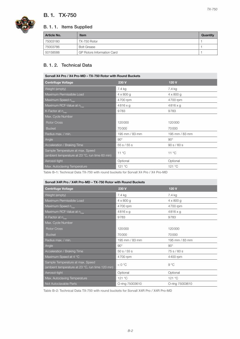
B-2
TX-750
B. 1. TX-750
B. 1. 1. Items Supplied
Article No. Item Quantity
75003180 TX-750 Rotor 1
75003786 Bolt Grease 1
50158588 GP Rotors Information Card 1
B. 1. 2. Technical Data
Sorvall X4 Pro / X4 Pro-MD – TX-750 Rotor with Round Buckets
Centrifuge Voltage 230 V 120 V
Weight (empty) 7.4 kg 7.4 kg
Maximum Permissibile Load 4 x 800 g 4 x 800 g
Maximum Speed nmax 4 700 rpm 4 700 rpm
Maximum RCF-Value at nmax 4 816 x g 4 816 x g
K-Factor at nmax 9 783 9 783
Max. Cycle Number
Rotor Cross
Bucket
120 000
70 000
120 000
70 000
Radius max. / min. 195 mm / 83 mm 195 mm / 83 mm
Angle 90° 90°
Acceleration / Braking Time 55 s / 55 s 90 s / 60 s
Sample Temperature at max. Speed (ambient temperature at 23 °C, run time 60 min)
11 °C 11 °C
Aerosol-tight Optional Optional
Max. Autoclaving Temperature 121 °C 121 °C
Table B–1: Technical Data TX-750 with round buckets for Sorvall X4 Pro / X4 Pro-MD
Sorvall X4R Pro / X4R Pro-MD – TX-750 Rotor with Round Buckets
Centrifuge Voltage 230 V 120 V
Weight (empty) 7.4 kg 7.4 kg
Maximum Permissibile Load 4 x 800 g 4 x 800 g
Maximum Speed nmax 4 700 rpm 4 700 rpm
Maximum RCF-Value at nmax 4 816 x g 4 816 x g
K-Factor at nmax 9 783 9 783
Max. Cycle Number
Rotor Cross
Bucket
120 000
70 000
120 000
70 000
Radius max. / min. 195 mm / 83 mm 195 mm / 83 mm
Angle 90° 90°
Acceleration / Braking Time 50 s / 55 s 75 s / 60 s
Maximum Speed at 4 °C 4 700 rpm 4 400 rpm
Sample Temperature at max. Speed (ambient temperature at 23 °C, run time 120 min)
< 0 °C 9 °C
Aerosol-tight Optional Optional
Max. Autoclaving Temperature 121 °C 121 °C
Not Autoclavable Parts O-ring 75003610 O-ring 75003610
Table B–2: Technical Data TX-750 with round buckets for Sorvall X4R Pro / X4R Pro-MD

B-3
TX-750
Sorvall ST4 Plus / ST4 Plus-MD – TX-750 Rotor with Round Buckets
Centrifuge Voltage 230 V 120 V
Weight (empty) 7.4 kg 7.4 kg
Maximum Permissibile Load 4 x 800 g 4 x 800 g
Maximum Speed nmax 4 700 rpm 4 700 rpm
Maximum RCF-Value at nmax 4 816 x g 4 816 x g
K-Factor at nmax 9 783 9 783
Max. Cycle Number
Rotor Cross
Bucket
120 000
70 000
120 000
70 000
Radius max. / min. 195 mm / 83 mm 195 mm / 83 mm
Angle 90° 90°
Acceleration / Braking Time 55 s / 55 s 90 s / 60 s
Sample Temperature at max. Speed (ambient temperature at 23 °C, run time 60 min)
11 °C 11 °C
Aerosol-tight Optional Optional
Max. Autoclaving Temperature 121 °C 121 °C
Not Autoclavable Parts O-ring 75003610 O-ring 75003610
Table B–3: Technical Data TX-750 with round buckets for Sorvall ST4 Plus / ST4 Plus-MD
Sorvall ST4R Plus / ST4R Plus-MD – TX-750 Rotor with Round Buckets
Centrifuge Voltage 230 V 120 V
Weight (empty) 7.4 kg 7.4 kg
Maximum Permissibile Load 4 x 800 g 4 x 800 g
Maximum Speed nmax 4 700 rpm 4 700 rpm
Maximum RCF-Value at nmax 4 816 x g 4 816 x g
K-Factor at nmax 9 783 9 783
Max. Cycle Number
Rotor Cross
Bucket
120 000
70 000
120 000
70 000
Radius max. / min. 195 mm / 83 mm 195 mm / 83 mm
Angle 90° 90°
Acceleration / Braking Time 50 s / 55 s 75 s / 60 s
Maximum Speed at 4 °C 4 700 rpm 4 400 rpm
Sample Temperature at max. Speed (ambient temperature at 23 °C, run time 120 min)
< 0 °C < 0 °C
Aerosol-tight Optional Optional
Max. Autoclaving Temperature 121 °C 121 °C
Not Autoclavable Parts O-ring 75003610 O-ring 75003610
Table B–4: Technical Data TX-750 with round buckets for Sorvall ST4R Plus / ST4R Plus-MD
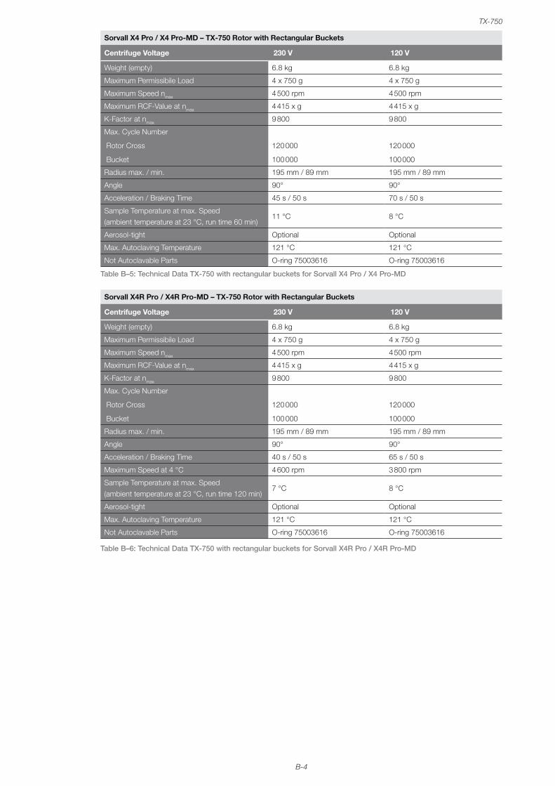
B-4
TX-750
Sorvall X4 Pro / X4 Pro-MD – TX-750 Rotor with Rectangular Buckets
Centrifuge Voltage 230 V 120 V
Weight (empty) 6.8 kg 6.8 kg
Maximum Permissibile Load 4 x 750 g 4 x 750 g
Maximum Speed nmax 4 500 rpm 4 500 rpm
Maximum RCF-Value at nmax 4 415 x g 4 415 x g
K-Factor at nmax 9 800 9 800
Max. Cycle Number
Rotor Cross
Bucket
120 000
100 000
120 000
100 000
Radius max. / min. 195 mm / 89 mm 195 mm / 89 mm
Angle 90° 90°
Acceleration / Braking Time 45 s / 50 s 70 s / 50 s
Sample Temperature at max. Speed (ambient temperature at 23 °C, run time 60 min)
11 °C 8 °C
Aerosol-tight Optional Optional
Max. Autoclaving Temperature 121 °C 121 °C
Not Autoclavable Parts O-ring 75003616 O-ring 75003616
Table B–5: Technical Data TX-750 with rectangular buckets for Sorvall X4 Pro / X4 Pro-MD
Sorvall X4R Pro / X4R Pro-MD – TX-750 Rotor with Rectangular Buckets
Centrifuge Voltage 230 V 120 V
Weight (empty) 6.8 kg 6.8 kg
Maximum Permissibile Load 4 x 750 g 4 x 750 g
Maximum Speed nmax 4 500 rpm 4 500 rpm
Maximum RCF-Value at nmax 4 415 x g 4 415 x g
K-Factor at nmax 9 800 9 800
Max. Cycle Number
Rotor Cross
Bucket
120 000
100 000
120 000
100 000
Radius max. / min. 195 mm / 89 mm 195 mm / 89 mm
Angle 90° 90°
Acceleration / Braking Time 40 s / 50 s 65 s / 50 s
Maximum Speed at 4 °C 4 600 rpm 3 800 rpm
Sample Temperature at max. Speed (ambient temperature at 23 °C, run time 120 min)
7 °C 8 °C
Aerosol-tight Optional Optional
Max. Autoclaving Temperature 121 °C 121 °C
Not Autoclavable Parts O-ring 75003616 O-ring 75003616
Table B–6: Technical Data TX-750 with rectangular buckets for Sorvall X4R Pro / X4R Pro-MD

B-5
TX-750
Sorvall ST4 Plus / ST4 Plus-MD – TX-750 Rotor with Rectangular Buckets
Centrifuge Voltage 230 V 120 V
Weight (empty) 6.8 kg 6.8 kg
Maximum Permissibile Load 4 x 750 g 4 x 750 g
Maximum Speed nmax 4 500 rpm 4 500 rpm
Maximum RCF-Value at nmax 4 415 x g 4 415 x g
K-Factor at nmax 9 800 9 800
Max. Cycle Number
Rotor Cross
Bucket
120 000
100 000
120 000
100 000
Radius max. / min. 195 mm / 89 mm 195 mm / 89 mm
Angle 90° 90°
Acceleration / Braking Time 45 s / 50 s 70 s / 50 s
Sample Temperature at max. Speed (ambient temperature at 23 °C, run time 60 min)
11 °C 8 °C
Aerosol-tight Optional Optional
Max. Autoclaving Temperature 121 °C 121 °C
Not Autoclavable Parts O-ring 75003616 O-ring 75003616
Table B–7: Technical Data TX-750 with rectangular buckets for Sorvall ST4 Plus / ST4 Plus-MD
Sorvall ST4R Plus / ST4R Plus-MD – TX-750 Rotor with Rectangular Buckets
Centrifuge Voltage 230 V 120 V
Weight (empty) 6.8 kg 6.8 kg
Maximum Permissibile Load 4 x 750 g 4 x 750 g
Maximum Speed nmax 4 500 rpm 4 500 rpm
Maximum RCF-Value at nmax 4 415 x g 4 415 x g
K-Factor at nmax 9 800 9 800
Max. Cycle Number
Rotor Cross
Bucket
120 000
100 000
120 000
100 000
Radius max. / min. 195 mm / 89 mm 195 mm / 89 mm
Angle 90° 90°
Acceleration / Braking Time 40 s / 50 s 65 s / 50 s
Maximum Speed at 4 °C 4 600 rpm 3 800 rpm
Sample Temperature at max. Speed (ambient temperature at 23 °C, run time 120 min)
7 °C 8 °C
Aerosol-tight Optional Optional
Max. Autoclaving Temperature 121 °C 121 °C
Not Autoclavable Parts O-ring 75003616 O-ring 75003616
Table B–8: Technical Data TX-750 with rectangular buckets for Sorvall ST4R Plus / ST4R Plus-MD
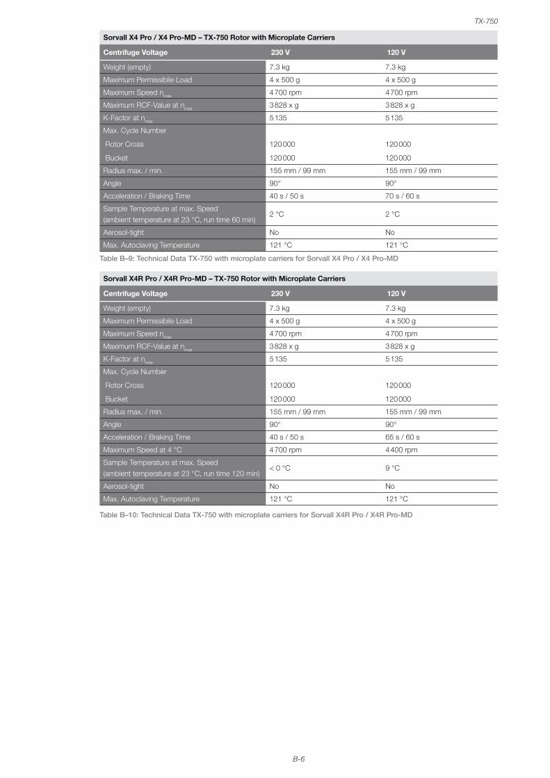
B-6
TX-750
Sorvall X4 Pro / X4 Pro-MD – TX-750 Rotor with Microplate Carriers
Centrifuge Voltage 230 V 120 V
Weight (empty) 7.3 kg 7.3 kg
Maximum Permissibile Load 4 x 500 g 4 x 500 g
Maximum Speed nmax 4 700 rpm 4 700 rpm
Maximum RCF-Value at nmax 3 828 x g 3 828 x g
K-Factor at nmax 5 135 5 135
Max. Cycle Number
Rotor Cross
Bucket
120 000
120 000
120 000
120 000
Radius max. / min. 155 mm / 99 mm 155 mm / 99 mm
Angle 90° 90°
Acceleration / Braking Time 40 s / 50 s 70 s / 60 s
Sample Temperature at max. Speed (ambient temperature at 23 °C, run time 60 min)
2 °C 2 °C
Aerosol-tight No No
Max. Autoclaving Temperature 121 °C 121 °C
Table B–9: Technical Data TX-750 with microplate carriers for Sorvall X4 Pro / X4 Pro-MD
Sorvall X4R Pro / X4R Pro-MD – TX-750 Rotor with Microplate Carriers
Centrifuge Voltage 230 V 120 V
Weight (empty) 7.3 kg 7.3 kg
Maximum Permissibile Load 4 x 500 g 4 x 500 g
Maximum Speed nmax 4 700 rpm 4 700 rpm
Maximum RCF-Value at nmax 3 828 x g 3 828 x g
K-Factor at nmax 5 135 5 135
Max. Cycle Number
Rotor Cross
Bucket
120 000
120 000
120 000
120 000
Radius max. / min. 155 mm / 99 mm 155 mm / 99 mm
Angle 90° 90°
Acceleration / Braking Time 40 s / 50 s 65 s / 60 s
Maximum Speed at 4 °C 4 700 rpm 4 400 rpm
Sample Temperature at max. Speed (ambient temperature at 23 °C, run time 120 min)
< 0 °C 9 °C
Aerosol-tight No No
Max. Autoclaving Temperature 121 °C 121 °C
Table B–10: Technical Data TX-750 with microplate carriers for Sorvall X4R Pro / X4R Pro-MD
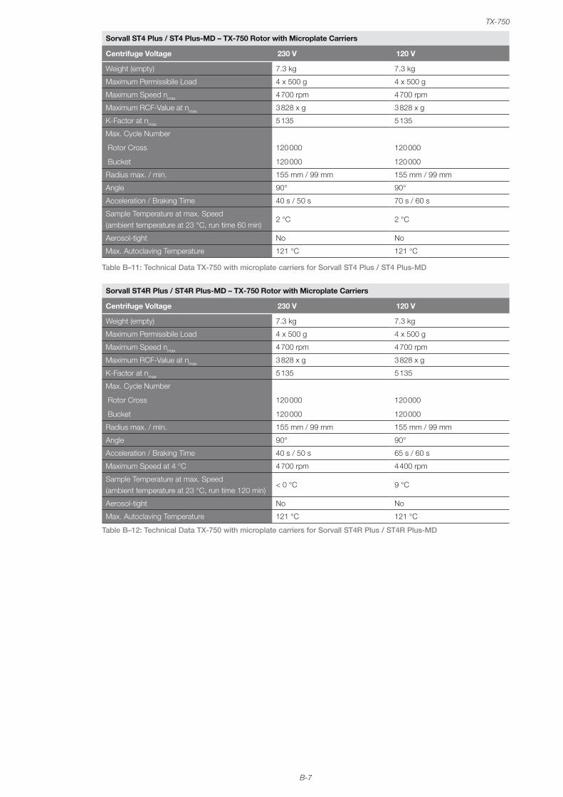
B-7
TX-750
Sorvall ST4 Plus / ST4 Plus-MD – TX-750 Rotor with Microplate Carriers
Centrifuge Voltage 230 V 120 V
Weight (empty) 7.3 kg 7.3 kg
Maximum Permissibile Load 4 x 500 g 4 x 500 g
Maximum Speed nmax 4 700 rpm 4 700 rpm
Maximum RCF-Value at nmax 3 828 x g 3 828 x g
K-Factor at nmax 5 135 5 135
Max. Cycle Number
Rotor Cross
Bucket
120 000
120 000
120 000
120 000
Radius max. / min. 155 mm / 99 mm 155 mm / 99 mm
Angle 90° 90°
Acceleration / Braking Time 40 s / 50 s 70 s / 60 s
Sample Temperature at max. Speed (ambient temperature at 23 °C, run time 60 min)
2 °C 2 °C
Aerosol-tight No No
Max. Autoclaving Temperature 121 °C 121 °C
Table B–11: Technical Data TX-750 with microplate carriers for Sorvall ST4 Plus / ST4 Plus-MD
Sorvall ST4R Plus / ST4R Plus-MD – TX-750 Rotor with Microplate Carriers
Centrifuge Voltage 230 V 120 V
Weight (empty) 7.3 kg 7.3 kg
Maximum Permissibile Load 4 x 500 g 4 x 500 g
Maximum Speed nmax 4 700 rpm 4 700 rpm
Maximum RCF-Value at nmax 3 828 x g 3 828 x g
K-Factor at nmax 5 135 5 135
Max. Cycle Number
Rotor Cross
Bucket
120 000
120 000
120 000
120 000
Radius max. / min. 155 mm / 99 mm 155 mm / 99 mm
Angle 90° 90°
Acceleration / Braking Time 40 s / 50 s 65 s / 60 s
Maximum Speed at 4 °C 4 700 rpm 4 400 rpm
Sample Temperature at max. Speed (ambient temperature at 23 °C, run time 120 min)
< 0 °C 9 °C
Aerosol-tight No No
Max. Autoclaving Temperature 121 °C 121 °C
Table B–12: Technical Data TX-750 with microplate carriers for Sorvall ST4R Plus / ST4R Plus-MD
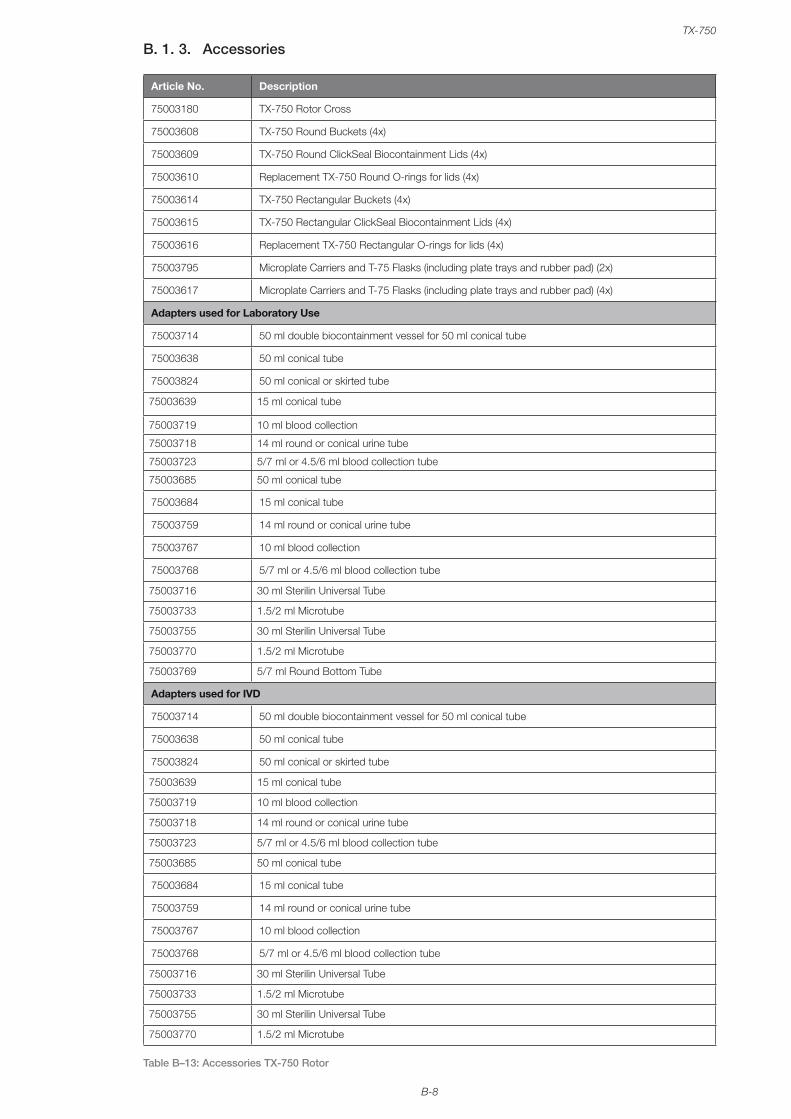
B-8
TX-750
B. 1. 3. Accessories
Article No. Description
75003180 TX-750 Rotor Cross
75003608 TX-750 Round Buckets (4x)
75003609 TX-750 Round ClickSeal Biocontainment Lids (4x)
75003610 Replacement TX-750 Round O-rings for lids (4x)
75003614 TX-750 Rectangular Buckets (4x)
75003615 TX-750 Rectangular ClickSeal Biocontainment Lids (4x)
75003616 Replacement TX-750 Rectangular O-rings for lids (4x)
75003795 Microplate Carriers and T-75 Flasks (including plate trays and rubber pad) (2x)
75003617 Microplate Carriers and T-75 Flasks (including plate trays and rubber pad) (4x)
Adapters used for Laboratory Use
75003714 50 ml double biocontainment vessel for 50 ml conical tube
75003638 50 ml conical tube
75003824 50 ml conical or skirted tube
75003639 15 ml conical tube
75003719 10 ml blood collection
75003718 14 ml round or conical urine tube
75003723 5/7 ml or 4.5/6 ml blood collection tube
75003685 50 ml conical tube
75003684 15 ml conical tube
75003759 14 ml round or conical urine tube
75003767 10 ml blood collection
75003768 5/7 ml or 4.5/6 ml blood collection tube
75003716 30 ml Sterilin Universal Tube
75003733 1.5/2 ml Microtube
75003755 30 ml Sterilin Universal Tube
75003770 1.5/2 ml Microtube
75003769 5/7 ml Round Bottom Tube
Adapters used for IVD
75003714 50 ml double biocontainment vessel for 50 ml conical tube
75003638 50 ml conical tube
75003824 50 ml conical or skirted tube
75003639 15 ml conical tube
75003719 10 ml blood collection
75003718 14 ml round or conical urine tube
75003723 5/7 ml or 4.5/6 ml blood collection tube
75003685 50 ml conical tube
75003684 15 ml conical tube
75003759 14 ml round or conical urine tube
75003767 10 ml blood collection
75003768 5/7 ml or 4.5/6 ml blood collection tube
75003716 30 ml Sterilin Universal Tube
75003733 1.5/2 ml Microtube
75003755 30 ml Sterilin Universal Tube
75003770 1.5/2 ml Microtube
Table B–13: Accessories TX-750 Rotor
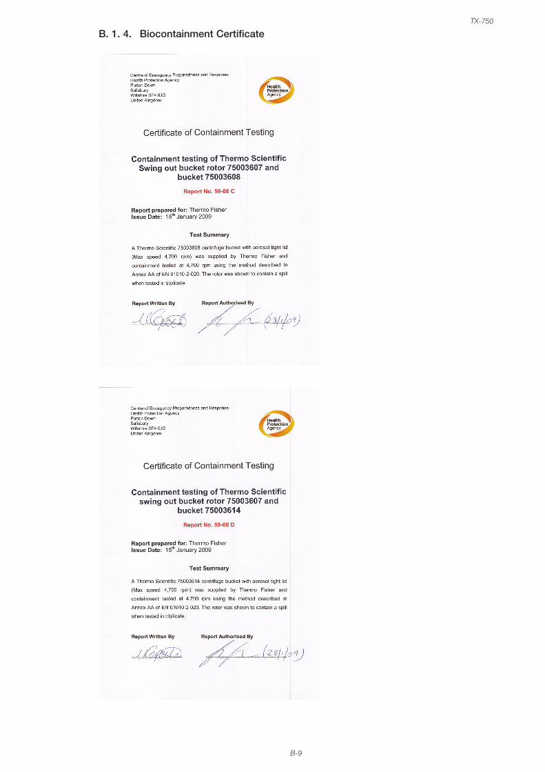
B-9
TX-750
B. 1. 4. Biocontainment Certificate
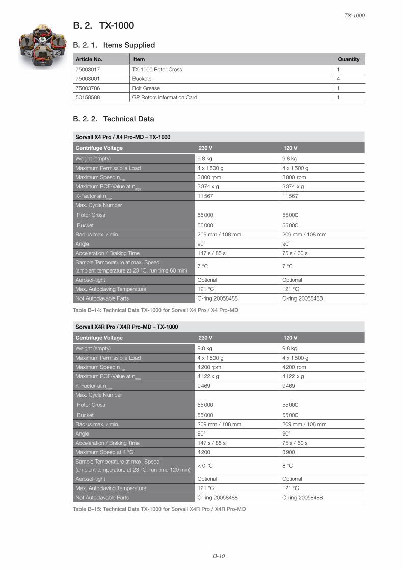
B-10
TX-1000
B. 2. TX-1000
B. 2. 1. Items Supplied
Article No. Item Quantity
75003017 TX-1000 Rotor Cross 1
75003001 Buckets 4
75003786 Bolt Grease 1
50158588 GP Rotors Information Card 1
B. 2. 2. Technical Data
Sorvall X4 Pro / X4 Pro-MD – TX-1000
Centrifuge Voltage 230 V 120 V
Weight (empty) 9.8 kg 9.8 kg
Maximum Permissibile Load 4 x 1 500 g 4 x 1 500 g
Maximum Speed nmax 3 800 rpm 3 800 rpm
Maximum RCF-Value at nmax 3 374 x g 3 374 x g
K-Factor at nmax 11 567 11 567
Max. Cycle Number
Rotor Cross
Bucket
55 000
55 000
55 000
55 000
Radius max. / min. 209 mm / 108 mm 209 mm / 108 mm
Angle 90° 90°
Acceleration / Braking Time 147 s / 85 s 75 s / 60 s
Sample Temperature at max. Speed (ambient temperature at 23 °C, run time 60 min)
7 °C 7 °C
Aerosol-tight Optional Optional
Max. Autoclaving Temperature 121 °C 121 °C
Not Autoclavable Parts O-ring 20058488 O-ring 20058488
Table B–14: Technical Data TX-1000 for Sorvall X4 Pro / X4 Pro-MD
Sorvall X4R Pro / X4R Pro-MD – TX-1000
Centrifuge Voltage 230 V 120 V
Weight (empty) 9.8 kg 9.8 kg
Maximum Permissibile Load 4 x 1 500 g 4 x 1 500 g
Maximum Speed nmax 4 200 rpm 4 200 rpm
Maximum RCF-Value at nmax 4 122 x g 4 122 x g
K-Factor at nmax 9 469 9 469
Max. Cycle Number
Rotor Cross
Bucket
55 000
55 000
55 000
55 000
Radius max. / min. 209 mm / 108 mm 209 mm / 108 mm
Angle 90° 90°
Acceleration / Braking Time 147 s / 85 s 75 s / 60 s
Maximum Speed at 4 °C 4 200 3 900
Sample Temperature at max. Speed (ambient temperature at 23 °C, run time 120 min)
< 0 °C 8 °C
Aerosol-tight Optional Optional
Max. Autoclaving Temperature 121 °C 121 °C
Not Autoclavable Parts O-ring 20058488 O-ring 20058488
Table B–15: Technical Data TX-1000 for Sorvall X4R Pro / X4R Pro-MD
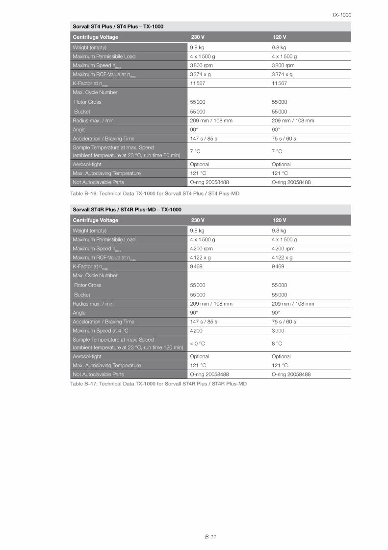
B-11
TX-1000
Sorvall ST4 Plus / ST4 Plus – TX-1000
Centrifuge Voltage 230 V 120 V
Weight (empty) 9.8 kg 9.8 kg
Maximum Permissibile Load 4 x 1 500 g 4 x 1 500 g
Maximum Speed nmax 3 800 rpm 3 800 rpm
Maximum RCF-Value at nmax 3 374 x g 3 374 x g
K-Factor at nmax 11 567 11 567
Max. Cycle Number
Rotor Cross
Bucket
55 000
55 000
55 000
55 000
Radius max. / min. 209 mm / 108 mm 209 mm / 108 mm
Angle 90° 90°
Acceleration / Braking Time 147 s / 85 s 75 s / 60 s
Sample Temperature at max. Speed (ambient temperature at 23 °C, run time 60 min)
7 °C 7 °C
Aerosol-tight Optional Optional
Max. Autoclaving Temperature 121 °C 121 °C
Not Autoclavable Parts O-ring 20058488 O-ring 20058488
Table B–16: Technical Data TX-1000 for Sorvall ST4 Plus / ST4 Plus-MD
Sorvall ST4R Plus / ST4R Plus-MD – TX-1000
Centrifuge Voltage 230 V 120 V
Weight (empty) 9.8 kg 9.8 kg
Maximum Permissibile Load 4 x 1 500 g 4 x 1 500 g
Maximum Speed nmax 4 200 rpm 4 200 rpm
Maximum RCF-Value at nmax 4 122 x g 4 122 x g
K-Factor at nmax 9 469 9 469
Max. Cycle Number
Rotor Cross
Bucket
55 000
55 000
55 000
55 000
Radius max. / min. 209 mm / 108 mm 209 mm / 108 mm
Angle 90° 90°
Acceleration / Braking Time 147 s / 85 s 75 s / 60 s
Maximum Speed at 4 °C 4 200 3 900
Sample Temperature at max. Speed (ambient temperature at 23 °C, run time 120 min)
< 0 °C 8 °C
Aerosol-tight Optional Optional
Max. Autoclaving Temperature 121 °C 121 °C
Not Autoclavable Parts O-ring 20058488 O-ring 20058488
Table B–17: Technical Data TX-1000 for Sorvall ST4R Plus / ST4R Plus-MD
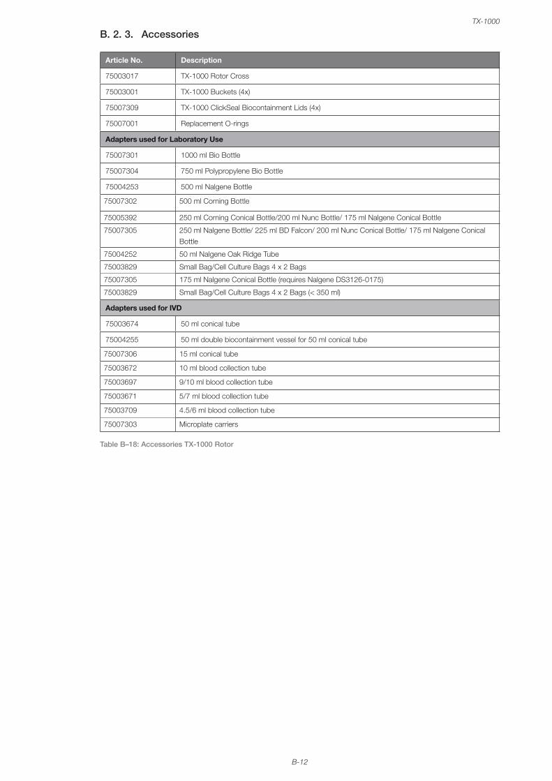
B-12
TX-1000
B. 2. 3. Accessories
Article No. Description
75003017 TX-1000 Rotor Cross
75003001 TX-1000 Buckets (4x)
75007309 TX-1000 ClickSeal Biocontainment Lids (4x)
75007001 Replacement O-rings
Adapters used for Laboratory Use
75007301 1000 ml Bio Bottle
75007304 750 ml Polypropylene Bio Bottle
75004253 500 ml Nalgene Bottle
75007302 500 ml Corning Bottle
75005392 250 ml Corning Conical Bottle/200 ml Nunc Bottle/ 175 ml Nalgene Conical Bottle
75007305 250 ml Nalgene Bottle/ 225 ml BD Falcon/ 200 ml Nunc Conical Bottle/ 175 ml Nalgene Conical Bottle
75004252 50 ml Nalgene Oak Ridge Tube
75003829 Small Bag/Cell Culture Bags 4 x 2 Bags
75007305 175 ml Nalgene Conical Bottle (requires Nalgene DS3126-0175)
75003829 Small Bag/Cell Culture Bags 4 x 2 Bags (< 350 ml)
Adapters used for IVD
75003674 50 ml conical tube
75004255 50 ml double biocontainment vessel for 50 ml conical tube
75007306 15 ml conical tube
75003672 10 ml blood collection tube
75003697 9/10 ml blood collection tube
75003671 5/7 ml blood collection tube
75003709 4.5/6 ml blood collection tube
75007303 Microplate carriers
Table B–18: Accessories TX-1000 Rotor
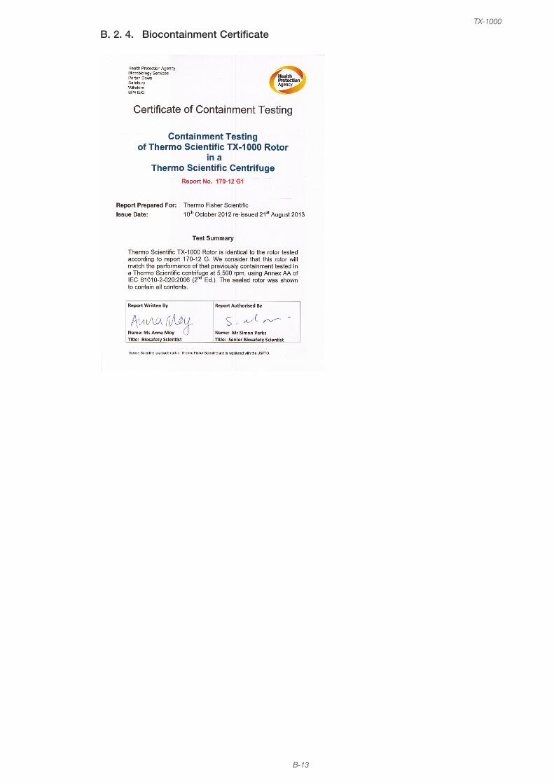
B-13
TX-1000
B. 2. 4. Biocontainment Certificate
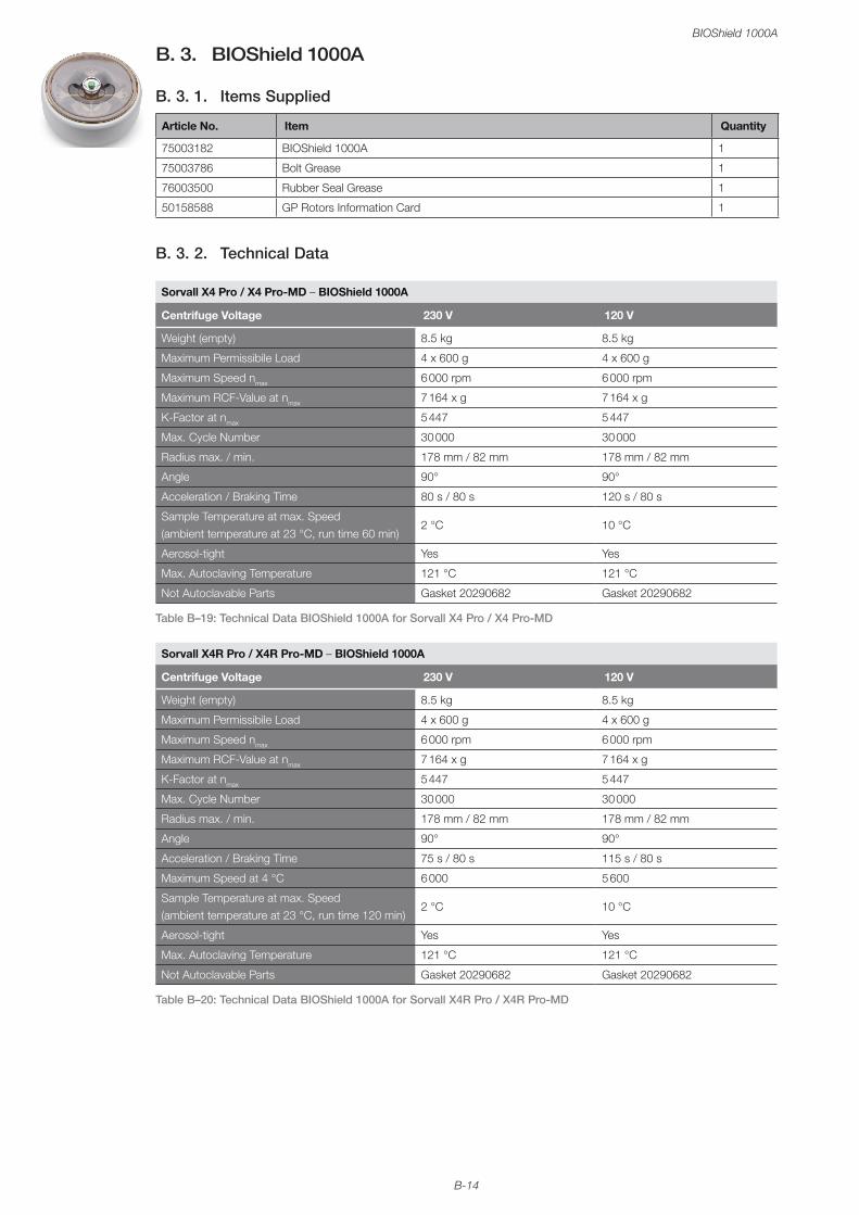
B-14
BIOShield 1000A
B. 3. BIOShield 1000A
B. 3. 1. Items Supplied
Article No. Item Quantity
75003182 BIOShield 1000A 1
75003786 Bolt Grease 1
76003500 Rubber Seal Grease 1
50158588 GP Rotors Information Card 1
B. 3. 2. Technical Data
Sorvall X4 Pro / X4 Pro-MD – BIOShield 1000A
Centrifuge Voltage 230 V 120 V
Weight (empty) 8.5 kg 8.5 kg
Maximum Permissibile Load 4 x 600 g 4 x 600 g
Maximum Speed nmax 6 000 rpm 6 000 rpm
Maximum RCF-Value at nmax 7 164 x g 7 164 x g
K-Factor at nmax 5 447 5 447
Max. Cycle Number 30 000 30 000
Radius max. / min. 178 mm / 82 mm 178 mm / 82 mm
Angle 90° 90°
Acceleration / Braking Time 80 s / 80 s 120 s / 80 s
Sample Temperature at max. Speed (ambient temperature at 23 °C, run time 60 min)
2 °C 10 °C
Aerosol-tight Yes Yes
Max. Autoclaving Temperature 121 °C 121 °C
Not Autoclavable Parts Gasket 20290682 Gasket 20290682
Table B–19: Technical Data BIOShield 1000A for Sorvall X4 Pro / X4 Pro-MD
Sorvall X4R Pro / X4R Pro-MD – BIOShield 1000A
Centrifuge Voltage 230 V 120 V
Weight (empty) 8.5 kg 8.5 kg
Maximum Permissibile Load 4 x 600 g 4 x 600 g
Maximum Speed nmax 6 000 rpm 6 000 rpm
Maximum RCF-Value at nmax 7 164 x g 7 164 x g
K-Factor at nmax 5 447 5 447
Max. Cycle Number 30 000 30 000
Radius max. / min. 178 mm / 82 mm 178 mm / 82 mm
Angle 90° 90°
Acceleration / Braking Time 75 s / 80 s 115 s / 80 s
Maximum Speed at 4 °C 6 000 5 600
Sample Temperature at max. Speed (ambient temperature at 23 °C, run time 120 min)
2 °C 10 °C
Aerosol-tight Yes Yes
Max. Autoclaving Temperature 121 °C 121 °C
Not Autoclavable Parts Gasket 20290682 Gasket 20290682
Table B–20: Technical Data BIOShield 1000A for Sorvall X4R Pro / X4R Pro-MD
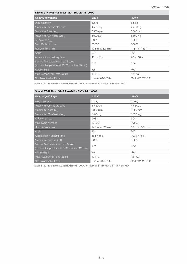
B-15
BIOShield 1000A
Sorvall ST4 Plus / ST4 Plus-MD – BIOShield 1000A
Centrifuge Voltage 230 V 120 V
Weight (empty) 8.5 kg 8.5 kg
Maximum Permissibile Load 4 x 600 g 4 x 600 g
Maximum Speed nmax 5 300 rpm 5 300 rpm
Maximum RCF-Value at nmax 5 590 x g 5 590 x g
K-Factor at nmax 6 981 6 981
Max. Cycle Number 30 000 30 000
Radius max. / min. 178 mm / 82 mm 178 mm / 82 mm
Angle 90° 90°
Acceleration / Braking Time 45 s / 50 s 70 s / 60 s
Sample Temperature at max. Speed (ambient temperature at 23 °C, run time 60 min)
8 °C 8 °C
Aerosol-tight Yes Yes
Max. Autoclaving Temperature 121 °C 121 °C
Not Autoclavable Parts Gasket 20290682 Gasket 20290682
Table B–21: Technical Data BIOShield 1000A for Sorvall ST4 Plus / ST4 Plus-MD
Sorvall ST4R Plus / ST4R Plus-MD – BIOShield 1000A
Centrifuge Voltage 230 V 120 V
Weight (empty) 8.5 kg 8.5 kg
Maximum Permissibile Load 4 x 600 g 4 x 600 g
Maximum Speed nmax 5 300 rpm 5 300 rpm
Maximum RCF-Value at nmax 5 590 x g 5 590 x g
K-Factor at nmax 6 981 6 981
Max. Cycle Number 30 000 30 000
Radius max. / min. 178 mm / 82 mm 178 mm / 82 mm
Angle 90° 90°
Acceleration / Braking Time 55 s / 55 s 100 s / 75 s
Maximum Speed at 4 °C 5 300 5 300
Sample Temperature at max. Speed (ambient temperature at 23 °C, run time 120 min)
1 °C 1 °C
Aerosol-tight Yes Yes
Max. Autoclaving Temperature 121 °C 121 °C
Not Autoclavable Parts Gasket 20290682 Gasket 20290682
Table B–22: Technical Data BIOShield 1000A for Sorvall ST4R Plus / ST4R Plus-MD
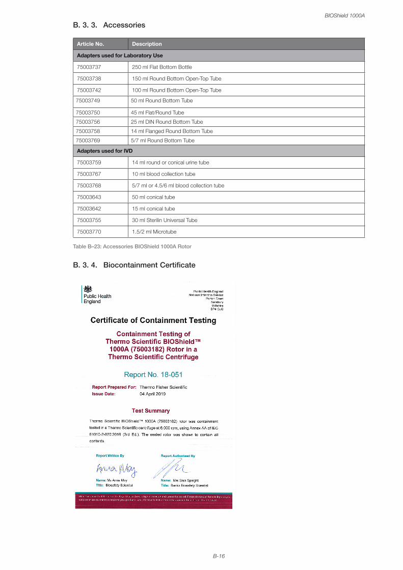
B-16
BIOShield 1000A
B. 3. 3. Accessories
Article No. Description
Adapters used for Laboratory Use
75003737 250 ml Flat Bottom Bottle
75003738 150 ml Round Bottom Open-Top Tube
75003742 100 ml Round Bottom Open-Top Tube
75003749 50 ml Round Bottom Tube
75003750 45 ml Flat/Round Tube
75003756 25 ml DIN Round Bottom Tube
75003758 14 ml Flanged Round Bottom Tube
75003769 5/7 ml Round Bottom Tube
Adapters used for IVD
75003759 14 ml round or conical urine tube
75003767 10 ml blood collection tube
75003768 5/7 ml or 4.5/6 ml blood collection tube
75003643 50 ml conical tube
75003642 15 ml conical tube
75003755 30 ml Sterilin Universal Tube
75003770 1.5/2 ml Microtube
Table B–23: Accessories BIOShield 1000A Rotor
B. 3. 4. Biocontainment Certificate
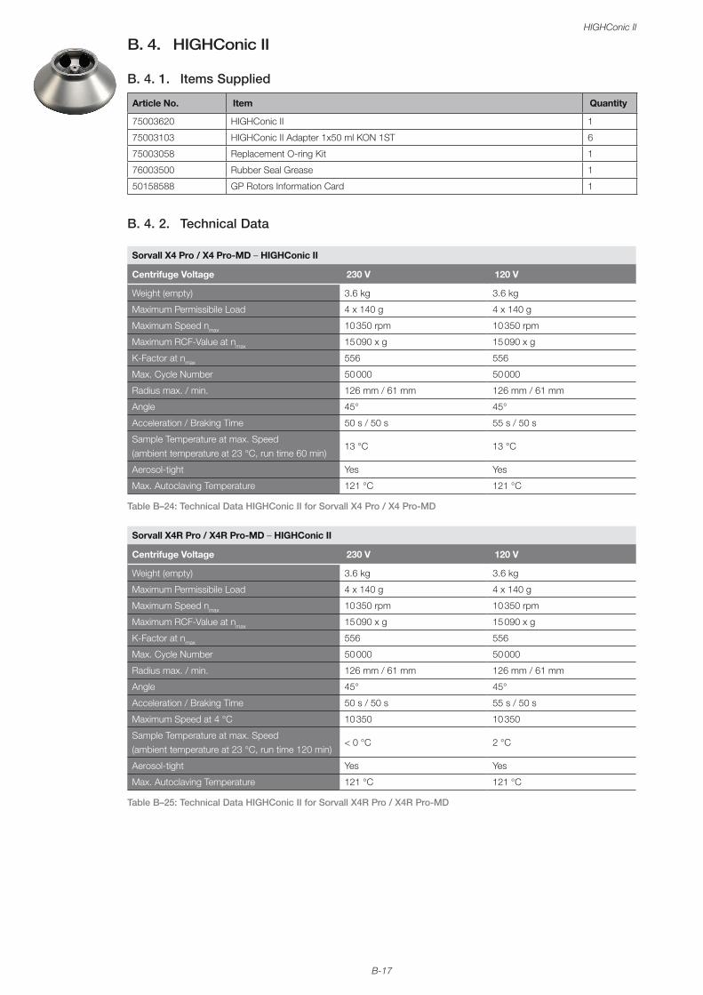
B-17
HIGHConic II
B. 4. HIGHConic II
B. 4. 1. Items Supplied
Article No. Item Quantity
75003620 HIGHConic II 1
75003103 HIGHConic II Adapter 1x50 ml KON 1ST 6
75003058 Replacement O-ring Kit 1
76003500 Rubber Seal Grease 1
50158588 GP Rotors Information Card 1
B. 4. 2. Technical Data
Sorvall X4 Pro / X4 Pro-MD – HIGHConic II
Centrifuge Voltage 230 V 120 V
Weight (empty) 3.6 kg 3.6 kg
Maximum Permissibile Load 4 x 140 g 4 x 140 g
Maximum Speed nmax 10 350 rpm 10 350 rpm
Maximum RCF-Value at nmax 15 090 x g 15 090 x g
K-Factor at nmax 556 556
Max. Cycle Number 50 000 50 000
Radius max. / min. 126 mm / 61 mm 126 mm / 61 mm
Angle 45° 45°
Acceleration / Braking Time 50 s / 50 s 55 s / 50 s
Sample Temperature at max. Speed (ambient temperature at 23 °C, run time 60 min)
13 °C 13 °C
Aerosol-tight Yes Yes
Max. Autoclaving Temperature 121 °C 121 °C
Table B–24: Technical Data HIGHConic II for Sorvall X4 Pro / X4 Pro-MD
Sorvall X4R Pro / X4R Pro-MD – HIGHConic II
Centrifuge Voltage 230 V 120 V
Weight (empty) 3.6 kg 3.6 kg
Maximum Permissibile Load 4 x 140 g 4 x 140 g
Maximum Speed nmax 10 350 rpm 10 350 rpm
Maximum RCF-Value at nmax 15 090 x g 15 090 x g
K-Factor at nmax 556 556
Max. Cycle Number 50 000 50 000
Radius max. / min. 126 mm / 61 mm 126 mm / 61 mm
Angle 45° 45°
Acceleration / Braking Time 50 s / 50 s 55 s / 50 s
Maximum Speed at 4 °C 10 350 10 350
Sample Temperature at max. Speed (ambient temperature at 23 °C, run time 120 min)
< 0 °C 2 °C
Aerosol-tight Yes Yes
Max. Autoclaving Temperature 121 °C 121 °C
Table B–25: Technical Data HIGHConic II for Sorvall X4R Pro / X4R Pro-MD
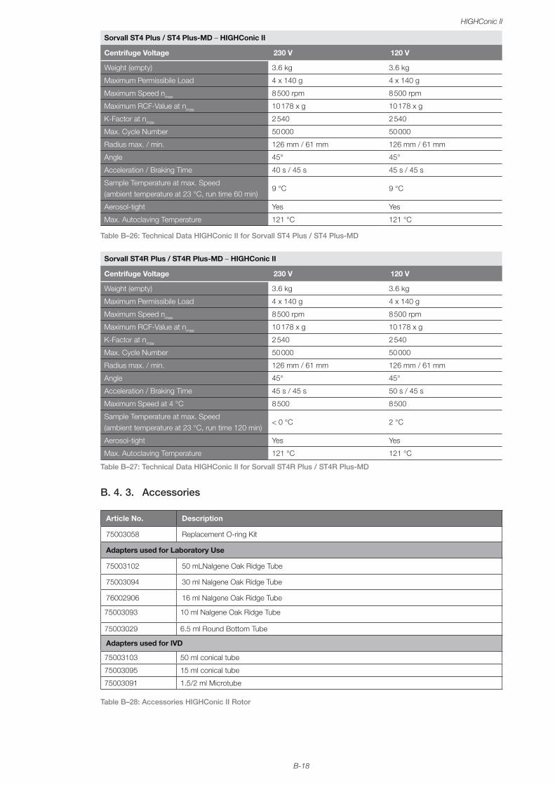
B-18
HIGHConic II
Sorvall ST4 Plus / ST4 Plus-MD – HIGHConic II
Centrifuge Voltage 230 V 120 V
Weight (empty) 3.6 kg 3.6 kg
Maximum Permissibile Load 4 x 140 g 4 x 140 g
Maximum Speed nmax 8 500 rpm 8 500 rpm
Maximum RCF-Value at nmax 10 178 x g 10 178 x g
K-Factor at nmax 2 540 2 540
Max. Cycle Number 50 000 50 000
Radius max. / min. 126 mm / 61 mm 126 mm / 61 mm
Angle 45° 45°
Acceleration / Braking Time 40 s / 45 s 45 s / 45 s
Sample Temperature at max. Speed (ambient temperature at 23 °C, run time 60 min)
9 °C 9 °C
Aerosol-tight Yes Yes
Max. Autoclaving Temperature 121 °C 121 °C
Table B–26: Technical Data HIGHConic II for Sorvall ST4 Plus / ST4 Plus-MD
Sorvall ST4R Plus / ST4R Plus-MD – HIGHConic II
Centrifuge Voltage 230 V 120 V
Weight (empty) 3.6 kg 3.6 kg
Maximum Permissibile Load 4 x 140 g 4 x 140 g
Maximum Speed nmax 8 500 rpm 8 500 rpm
Maximum RCF-Value at nmax 10 178 x g 10 178 x g
K-Factor at nmax 2 540 2 540
Max. Cycle Number 50 000 50 000
Radius max. / min. 126 mm / 61 mm 126 mm / 61 mm
Angle 45° 45°
Acceleration / Braking Time 45 s / 45 s 50 s / 45 s
Maximum Speed at 4 °C 8 500 8 500
Sample Temperature at max. Speed (ambient temperature at 23 °C, run time 120 min)
< 0 °C 2 °C
Aerosol-tight Yes Yes
Max. Autoclaving Temperature 121 °C 121 °C
Table B–27: Technical Data HIGHConic II for Sorvall ST4R Plus / ST4R Plus-MD
B. 4. 3. Accessories
Article No. Description
75003058 Replacement O-ring Kit
Adapters used for Laboratory Use
75003102 50 mLNalgene Oak Ridge Tube
75003094 30 ml Nalgene Oak Ridge Tube
76002906 16 ml Nalgene Oak Ridge Tube
75003093 10 ml Nalgene Oak Ridge Tube
75003029 6.5 ml Round Bottom Tube
Adapters used for IVD
75003103 50 ml conical tube
75003095 15 ml conical tube
75003091 1.5/2 ml Microtube
Table B–28: Accessories HIGHConic II Rotor
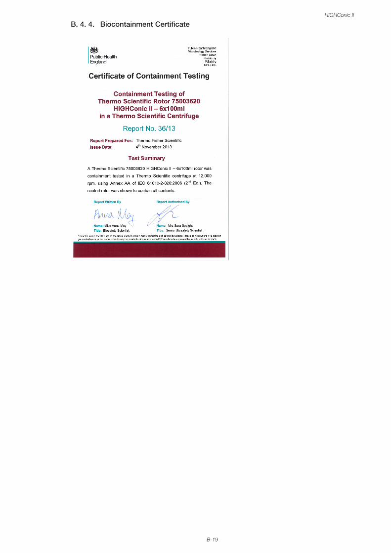
B-19
HIGHConic II
B. 4. 4. Biocontainment Certificate

B-20
Fiberlite F13-14 x 50cy
B. 5. Fiberlite F13-14 x 50cy
B. 5. 1. Items Supplied
Article No. Item Quantity
75003661* Fiberlite F13-14 x 50cy 1
50158588 GP Rotors Information Card 1
* Identical with 096-149027.
B. 5. 2. Technical Data
Sorvall X4 Pro / X4 Pro-MD – Fiberlite F13-14 x 50cy
Centrifuge Voltage 230 V 120 V
Weight (empty) 7.48 kg 7.48 kg
Maximum Permissibile Load 14 x 75 g 14 x 75 g
Maximum Speed nmax 10 000 rpm 9 250 rpm
Maximum RCF-Value at nmax 17 105 x g 14 636 x g
K-Factor at nmax 1 640 1 917
Max. Lifetime 15 years 15 years
Radius max. / min. 153 mm / 80 mm 153 mm / 80 mm
Angle 34° 34°
Acceleration / Braking Time 135 s / 90 s 145 s / 90 s
Sample Temperature at max. Speed (ambient temperature at 23 °C, run time 60 min)
21 °C 19 °C
Aerosol-tight Yes Yes
Max. Autoclaving Temperature 121 °C 121 °C
Table B–29: Technical Data Fiberlite F13-14 x 50cy for Sorvall X4 Pro / X4 Pro-MD
Sorvall X4R Pro / X4R Pro-MD – Fiberlite F13-14 x 50cy
Centrifuge Voltage 230 V 120 V
Weight (empty) 3.6 kg 3.6 kg
Maximum Permissibile Load 14 x 75 g 14 x 75 g
Maximum Speed nmax 10 350 rpm 10 350 rpm
Maximum RCF-Value at nmax 15 090 x g 15 090 x g
K-Factor at nmax 556 556
Max. Lifetime 15 years 15 years
Radius max. / min. 126 mm / 61 mm 126 mm / 61 mm
Angle 45° 45°
Acceleration / Braking Time 115 s / 90 s 135 s / 90 s
Maximum Speed at 4 °C 9 100 8 600
Sample Temperature at max. Speed (ambient temperature at 23 °C, run time 120 min)
11 °C 15 °C
Aerosol-tight Yes Yes
Max. Autoclaving Temperature 121 °C 121 °C
Table B–30: Technical Data Fiberlite F13-14 x 50cy for Sorvall X4R Pro / X4R Pro-MD
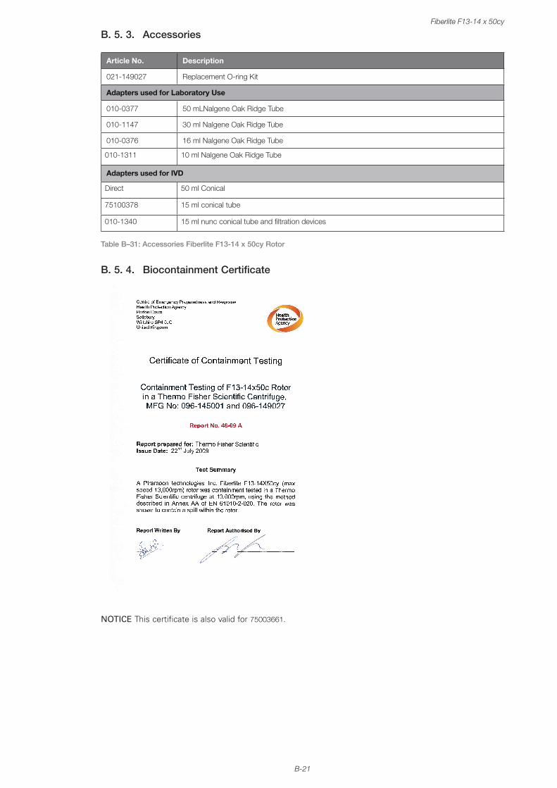
B-21
Fiberlite F13-14 x 50cy
B. 5. 3. Accessories
Article No. Description
021-149027 Replacement O-ring Kit
Adapters used for Laboratory Use
010-0377 50 mLNalgene Oak Ridge Tube
010-1147 30 ml Nalgene Oak Ridge Tube
010-0376 16 ml Nalgene Oak Ridge Tube
010-1311 10 ml Nalgene Oak Ridge Tube
Adapters used for IVD
Direct 50 ml Conical
75100378 15 ml conical tube
010-1340 15 ml nunc conical tube and filtration devices
Table B–31: Accessories Fiberlite F13-14 x 50cy Rotor
B. 5. 4. Biocontainment Certificate
NOTICE This certificate is also valid for 75003661.

B-22
Fiberlite F14-6 x 250 LE
B. 6. Fiberlite F14-6 x 250 LE
B. 6. 1. Items Supplied
Article No. Item Quantity
75003662* Fiberlite F14-6 x 250 LE 1
50158588 GP Rotors Information Card 1
* Identical with 096-062153.
B. 6. 2. Technical Data
Sorvall X4 Pro / X4 Pro-MD – Fiberlite F14-6 x 250 LE
Centrifuge Voltage 230 V 120 V
Weight (empty) 8.39 kg 8.39 kg
Maximum Permissibile Load 6 x 400 g 6 x 400 g
Maximum Speed nmax 11 000 rpm 10 000 rpm
Maximum RCF-Value at nmax 18 533 x g 15 317 x g
K-Factor at nmax 2 737 3 312
Max. Lifetime 15 years 15 years
Radius max. / min. 137 mm / 37 mm 137 mm / 37 mm
Angle 23° 23°
Acceleration / Braking Time 115 s / 85 s 130 s / 85 s
Sample Temperature at max. Speed (ambient temperature at 23 °C, run time 60 min)
17 °C 15 °C
Aerosol-tight Yes Yes
Max. Autoclaving Temperature 121 °C 121 °C
Table B–32: Technical Data Fiberlite F14-6 x 250 LE for Sorvall X4 Pro / X4 Pro-MD
Sorvall X4R Pro / X4 Pro-MD – Fiberlite F14-6 x 250 LE
Centrifuge Voltage 230 V 120 V
Weight (empty) 3.6 kg 3.6 kg
Maximum Permissibile Load 8.39 kg 8.39 kg
Maximum Speed nmax 6 x 400 g 6 x 400 g
Maximum RCF-Value at nmax 11 000 rpm 10 000 rpm
K-Factor at nmax 18 533 x g 15 317 x g
Max. Lifetime 15 years 15 years
Radius max. / min. 137 mm / 37 mm 137 mm / 37 mm
Angle 23° 23°
Acceleration / Braking Time 110 s / 85 s 125 s / 85 s
Maximum Speed at 4 °C 10 400 9 200
Sample Temperature at max. Speed (ambient temperature at 23 °C, run time 120 min)
9 °C 15 °C
Aerosol-tight Yes Yes
Max. Autoclaving Temperature 121 °C 121 °C
Table B–33: Technical Data Fiberlite F14-6 x 250 LE for Sorvall X4R Pro / X4R Pro-MD
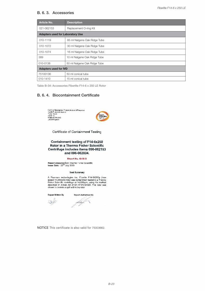
B-23
Fiberlite F14-6 x 250 LE
B. 6. 3. Accessories
Article No. Description
021-062153 Replacement O-ring Kit
Adapters used for Laboratory Use
010-1119 85 ml Nalgene Oak Ridge Tube
010-1072 30 ml Nalgene Oak Ridge Tube
010-1074 16 ml Nalgene Oak Ridge Tube
389 10 ml Nalgene Oak Ridge Tube
010-0138 50 ml Nalgene Oak Ridge Tube
Adapters used for IVD
75100136 50 ml conical tube
010-1410 15 ml conical tube
Table B–34: Accessories Fiberlite F14-6 x 250 LE Rotor
B. 6. 4. Biocontainment Certificate
NOTICE This certificate is also valid for 75003662.

B-24
Fiberlite F15-6 x 100y
B. 7. Fiberlite F15-6 x 100y
B. 7. 1. Items Supplied
Article No. Item Quantity
75003698* Fiberlite F15-6 x 100y 1
50158588 GP Rotors Information Card 1
* Identical with 096-069031.
B. 7. 2. Technical Data
Sorvall X4 Pro / X4 Pro-MD – Fiberlite F15-6 x 100y
Centrifuge Voltage 230 V 120 V
Weight (empty) 3.63 kg 3.63 kg
Maximum Permissibile Load 6 x 126 g 6 x 126 g
Maximum Speed nmax 15 000 rpm 13 000 rpm
Maximum RCF-Value at nmax 24 652 x g 18 516 x g
K-Factor at nmax 1 536 2 045
Max. Lifetime 15 years 15 years
Radius max. / min. 98 mm / 25 mm 98 mm / 25 mm
Angle 25° 25°
Acceleration / Braking Time 60 s / 55 s 70 s / 55 s
Sample Temperature at max. Speed (ambient temperature at 23 °C, run time 60 min)
21 °C 21 °C
Aerosol-tight Yes Yes
Max. Autoclaving Temperature 121 °C 121 °C
Table B–35: Technical Data Fiberlite F15-6 x 100y for Sorvall X4 Pro / X4 Pro-MD
Sorvall X4R Pro / X4 Pro-MD – Fiberlite F15-6 x 100y
Centrifuge Voltage 230 V 120 V
Weight (empty) 3.63 kg 3.63 kg
Maximum Permissibile Load 6 x 126 g 6 x 126 g
Maximum Speed nmax 15 000 rpm 13 000 rpm
Maximum RCF-Value at nmax 24 652 x g 18 516 x g
K-Factor at nmax 1 536 2 045
Max. Lifetime 15 years 15 years
Radius max. / min. 98 mm / 25 mm 98 mm / 25 mm
Angle 25° 25°
Acceleration / Braking Time 60 s / 55 s 65 s / 55 s
Maximum Speed at 4 °C 15 000 12 200
Sample Temperature at max. Speed (ambient temperature at 23 °C, run time 120 min)
2 °C 15 °C
Aerosol-tight Yes Yes
Max. Autoclaving Temperature 121 °C 121 °C
Table B–36: Technical Data Fiberlite F15-6 x 100y for Sorvall X4R Pro / X4R Pro-MD

B-25
Fiberlite F15-6 x 100y
Sorvall ST4 Plus / ST4 Plus-MD – Fiberlite F15-6 x 100y
Centrifuge Voltage 230 V 120 V
Weight (empty) 3.63 kg 3.63 kg
Maximum Permissibile Load 6 x 126 g 6 x 126 g
Maximum Speed nmax 15 000 rpm 13 000 rpm
Maximum RCF-Value at nmax 24 652 x g 18 516 x g
K-Factor at nmax 1 536 2 045
Max. Lifetime 15 years 15 years
Radius max. / min. 98 mm / 25 mm 98 mm / 25 mm
Angle 25° 25°
Acceleration / Braking Time 50 s / 50 s 55 s / 50 s
Sample Temperature at max. Speed (ambient temperature at 23 °C, run time 60 min)
14 °C 14 °C
Aerosol-tight Yes Yes
Max. Autoclaving Temperature 121 °C 121 °C
Table B–37: Technical Data Fiberlite F15-6 x 100y for Sorvall ST4 Plus / ST4 Plus-MD
Sorvall ST4R Plus / ST4R Plus-MD – Fiberlite F15-6 x 100y
Centrifuge Voltage 230 V 120 V
Weight (empty) 3.63 kg 3.63 kg
Maximum Permissibile Load 6 x 126 g 6 x 126 g
Maximum Speed nmax 15 000 rpm 13 000 rpm
Maximum RCF-Value at nmax 24 652 x g 18 516 x g
K-Factor at nmax 1 536 2 045
Max. Lifetime 15 years 15 years
Radius max. / min. 98 mm / 25 mm 98 mm / 25 mm
Angle 25° 25°
Acceleration / Braking Time 50 s / 45 s 55 s / 50 s
Maximum Speed at 4 °C 13 000 12 200
Sample Temperature at max. Speed (ambient temperature at 23 °C, run time 120 min)
< 0 °C 12 °C
Aerosol-tight Yes Yes
Max. Autoclaving Temperature 121 °C 121 °C
Table B–38: Technical Data Fiberlite F15-6 x 100y for Sorvall ST4R Plus / ST4R Plus-MD
B. 7. 3. Accessories
Article No. Description
021-069031 Replacement O-ring Kit
Adapters used for Laboratory Use
75003102 50 ml Nalgene Oak Ridge Tube
76002906 16 ml Nalgene Oak Ridge Tube
75003093 10 ml Nalgene Oak Ridge Tube / 12 ml Round Tube
75003092 6.5 ml Round Bottom Tube
75003094 30 ml Nalgene Oak Ridge Tube
Adapters used for IVD
75003103 50 ml conical tube
75003095 15 ml conical tube
75003091 1.5/2 ml Microtube
Table B–39: Accessories Fiberlite F15-6 x 100y Rotor
B-26
Fiberlite F15-6 x 100y
B. 7. 4. Biocontainment Certificate
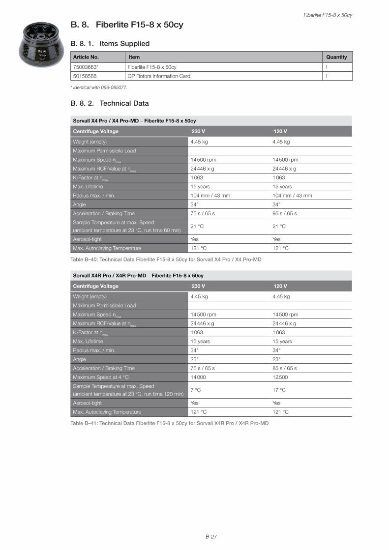
B-27
Fiberlite F15-8 x 50cy
B. 8. Fiberlite F15-8 x 50cy
B. 8. 1. Items Supplied
Article No. Item Quantity
75003663* Fiberlite F15-8 x 50cy 1
50158588 GP Rotors Information Card 1
* Identical with 096-085077.
B. 8. 2. Technical Data
Sorvall X4 Pro / X4 Pro-MD – Fiberlite F15-8 x 50cy
Centrifuge Voltage 230 V 120 V
Weight (empty) 4.45 kg 4.45 kg
Maximum Permissibile Load
Maximum Speed nmax 14 500 rpm 14 500 rpm
Maximum RCF-Value at nmax 24 446 x g 24 446 x g
K-Factor at nmax 1 063 1 063
Max. Lifetime 15 years 15 years
Radius max. / min. 104 mm / 43 mm 104 mm / 43 mm
Angle 34° 34°
Acceleration / Braking Time 75 s / 65 s 95 s / 65 s
Sample Temperature at max. Speed (ambient temperature at 23 °C, run time 60 min)
21 °C 21 °C
Aerosol-tight Yes Yes
Max. Autoclaving Temperature 121 °C 121 °C
Table B–40: Technical Data Fiberlite F15-8 x 50cy for Sorvall X4 Pro / X4 Pro-MD
Sorvall X4R Pro / X4R Pro-MD – Fiberlite F15-8 x 50cy
Centrifuge Voltage 230 V 120 V
Weight (empty) 4.45 kg 4.45 kg
Maximum Permissibile Load
Maximum Speed nmax 14 500 rpm 14 500 rpm
Maximum RCF-Value at nmax 24 446 x g 24 446 x g
K-Factor at nmax 1 063 1 063
Max. Lifetime 15 years 15 years
Radius max. / min. 34° 34°
Angle 23° 23°
Acceleration / Braking Time 75 s / 65 s 85 s / 65 s
Maximum Speed at 4 °C 14 000 12 500
Sample Temperature at max. Speed (ambient temperature at 23 °C, run time 120 min)
7 °C 17 °C
Aerosol-tight Yes Yes
Max. Autoclaving Temperature 121 °C 121 °C
Table B–41: Technical Data Fiberlite F15-8 x 50cy for Sorvall X4R Pro / X4R Pro-MD
B-28
Fiberlite F15-8 x 50cy
B. 8. 3. Accessories
Article No. Description
021-149027 Replacement O-ring Kit
Adapters used for Laboratory Use
010-0377 50 mLNalgene Oak Ridge Tube
010-1147 30 ml Nalgene Oak Ridge Tube
010-0376 16 ml Nalgene Oak Ridge Tube
010-1311 10 ml Nalgene Oak Ridge Tube
Table B–42: Accessories Fiberlite F15-8 x 50cy Rotor
B. 8. 4. Biocontainment Certificate
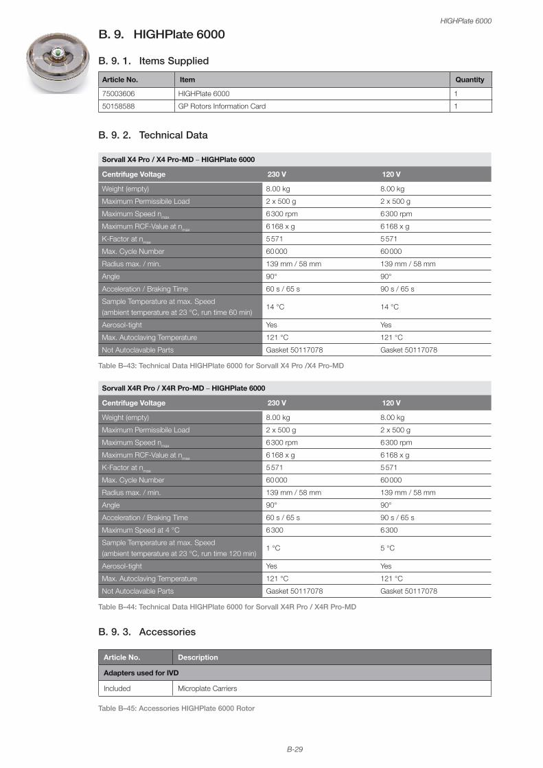
B-29
HIGHPlate 6000
B. 9. HIGHPlate 6000
B. 9. 1. Items Supplied
Article No. Item Quantity
75003606 HIGHPlate 6000 1
50158588 GP Rotors Information Card 1
B. 9. 2. Technical Data
Sorvall X4 Pro / X4 Pro-MD – HIGHPlate 6000
Centrifuge Voltage 230 V 120 V
Weight (empty) 8.00 kg 8.00 kg
Maximum Permissibile Load 2 x 500 g 2 x 500 g
Maximum Speed nmax 6 300 rpm 6 300 rpm
Maximum RCF-Value at nmax 6 168 x g 6 168 x g
K-Factor at nmax 5 571 5 571
Max. Cycle Number 60 000 60 000
Radius max. / min. 139 mm / 58 mm 139 mm / 58 mm
Angle 90° 90°
Acceleration / Braking Time 60 s / 65 s 90 s / 65 s
Sample Temperature at max. Speed (ambient temperature at 23 °C, run time 60 min)
14 °C 14 °C
Aerosol-tight Yes Yes
Max. Autoclaving Temperature 121 °C 121 °C
Not Autoclavable Parts Gasket 50117078 Gasket 50117078
Table B–43: Technical Data HIGHPlate 6000 for Sorvall X4 Pro /X4 Pro-MD
Sorvall X4R Pro / X4R Pro-MD – HIGHPlate 6000
Centrifuge Voltage 230 V 120 V
Weight (empty) 8.00 kg 8.00 kg
Maximum Permissibile Load 2 x 500 g 2 x 500 g
Maximum Speed nmax 6 300 rpm 6 300 rpm
Maximum RCF-Value at nmax 6 168 x g 6 168 x g
K-Factor at nmax 5 571 5 571
Max. Cycle Number 60 000 60 000
Radius max. / min. 139 mm / 58 mm 139 mm / 58 mm
Angle 90° 90°
Acceleration / Braking Time 60 s / 65 s 90 s / 65 s
Maximum Speed at 4 °C 6 300 6 300
Sample Temperature at max. Speed (ambient temperature at 23 °C, run time 120 min)
1 °C 5 °C
Aerosol-tight Yes Yes
Max. Autoclaving Temperature 121 °C 121 °C
Not Autoclavable Parts Gasket 50117078 Gasket 50117078
Table B–44: Technical Data HIGHPlate 6000 for Sorvall X4R Pro / X4R Pro-MD
B. 9. 3. Accessories
Article No. Description
Adapters used for IVD
Included Microplate Carriers
Table B–45: Accessories HIGHPlate 6000 Rotor
B-30
HIGHPlate 6000
B. 9. 4. Biocontainment Certificate
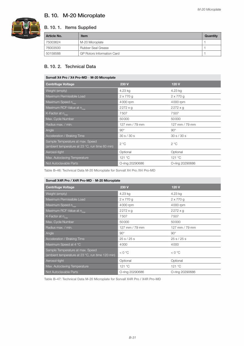
B-31
M-20 Microplate
B. 10. M-20 Microplate
B. 10. 1. Items Supplied
Article No. Item Quantity
75003624 M-20 Microplate 1
76003500 Rubber Seal Grease 1
50158588 GP Rotors Information Card 1
B. 10. 2. Technical Data
Sorvall X4 Pro / X4 Pro-MD – M-20 Microplate
Centrifuge Voltage 230 V 120 V
Weight (empty) 4.23 kg 4.23 kg
Maximum Permissibile Load 2 x 770 g 2 x 770 g
Maximum Speed nmax 4 000 rpm 4 000 rpm
Maximum RCF-Value at nmax 2 272 x g 2 272 x g
K-Factor at nmax 7 507 7 507
Max. Cycle Number 50 000 50 000
Radius max. / min. 127 mm / 79 mm 127 mm / 79 mm
Angle 90° 90°
Acceleration / Braking Time 30 s / 30 s 30 s / 30 s
Sample Temperature at max. Speed (ambient temperature at 23 °C, run time 60 min)
2 °C 2 °C
Aerosol-tight Optional Optional
Max. Autoclaving Temperature 121 °C 121 °C
Not Autoclavable Parts O-ring 20290686 O-ring 20290686
Table B–46: Technical Data M-20 Microplate for Sorvall X4 Pro /X4 Pro-MD
Sorvall X4R Pro / X4R Pro-MD – M-20 Microplate
Centrifuge Voltage 230 V 120 V
Weight (empty) 4.23 kg 4.23 kg
Maximum Permissibile Load 2 x 770 g 2 x 770 g
Maximum Speed nmax 4 000 rpm 4 000 rpm
Maximum RCF-Value at nmax 2 272 x g 2 272 x g
K-Factor at nmax 7 507 7 507
Max. Cycle Number 50 000 50 000
Radius max. / min. 127 mm / 79 mm 127 mm / 79 mm
Angle 90° 90°
Acceleration / Braking Time 25 s / 25 s 25 s / 25 s
Maximum Speed at 4 °C 4 000 4 000
Sample Temperature at max. Speed (ambient temperature at 23 °C, run time 120 min)
< 0 °C < 0 °C
Aerosol-tight Optional Optional
Max. Autoclaving Temperature 121 °C 121 °C
Not Autoclavable Parts O-ring 20290686 O-ring 20290686
Table B–47: Technical Data M-20 Microplate for Sorvall X4R Pro / X4R Pro-MD
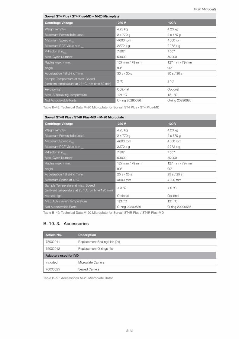
B-32
M-20 Microplate
Sorvall ST4 Plus / ST4 Plus-MD – M-20 Microplate
Centrifuge Voltage 230 V 120 V
Weight (empty) 4.23 kg 4.23 kg
Maximum Permissibile Load 2 x 770 g 2 x 770 g
Maximum Speed nmax 4 000 rpm 4 000 rpm
Maximum RCF-Value at nmax 2 272 x g 2 272 x g
K-Factor at nmax 7 507 7 507
Max. Cycle Number 50 000 50 000
Radius max. / min. 127 mm / 79 mm 127 mm / 79 mm
Angle 90° 90°
Acceleration / Braking Time 30 s / 30 s 30 s / 30 s
Sample Temperature at max. Speed (ambient temperature at 23 °C, run time 60 min)
2 °C 2 °C
Aerosol-tight Optional Optional
Max. Autoclaving Temperature 121 °C 121 °C
Not Autoclavable Parts O-ring 20290686 O-ring 20290686
Table B–48: Technical Data M-20 Microplate for Sorvall ST4 Plus / ST4 Plus-MD
Sorvall ST4R Plus / ST4R Plus-MD – M-20 Microplate
Centrifuge Voltage 230 V 120 V
Weight (empty) 4.23 kg 4.23 kg
Maximum Permissibile Load 2 x 770 g 2 x 770 g
Maximum Speed nmax 4 000 rpm 4 000 rpm
Maximum RCF-Value at nmax 2 272 x g 2 272 x g
K-Factor at nmax 7 507 7 507
Max. Cycle Number 50 000 50 000
Radius max. / min. 127 mm / 79 mm 127 mm / 79 mm
Angle 90° 90°
Acceleration / Braking Time 25 s / 25 s 25 s / 25 s
Maximum Speed at 4 °C 4 000 rpm 4 000 rpm
Sample Temperature at max. Speed (ambient temperature at 23 °C, run time 120 min)
< 0 °C < 0 °C
Aerosol-tight Optional Optional
Max. Autoclaving Temperature 121 °C 121 °C
Not Autoclavable Parts O-ring 20290686 O-ring 20290686
Table B–49: Technical Data M-20 Microplate for Sorvall ST4R Plus / ST4R Plus-MD
B. 10. 3. Accessories
Article No. Description
75002011 Replacement Sealing Lids (2x)
75002012 Replacement O-rings (4x)
Adapters used for IVD
Included Microplate Carriers
76003625 Sealed Carriers
Table B–50: Accessories M-20 Microplate Rotor
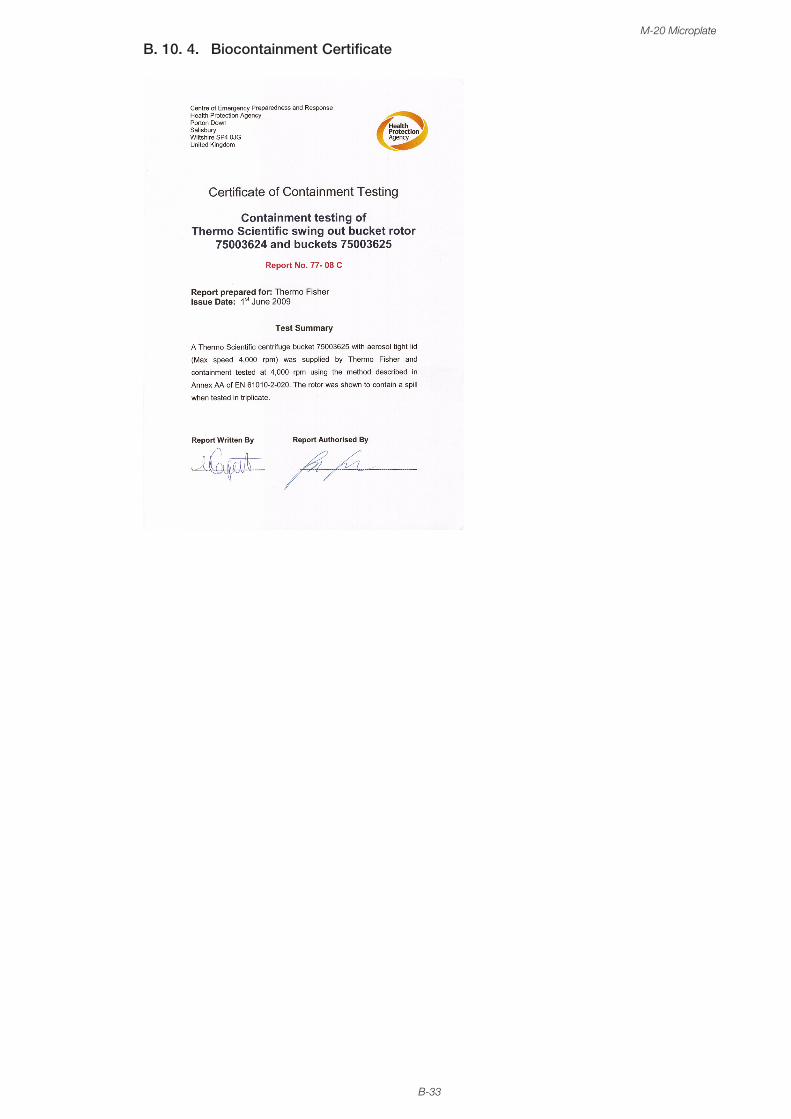
B-33
M-20 Microplate
B. 10. 4. Biocontainment Certificate
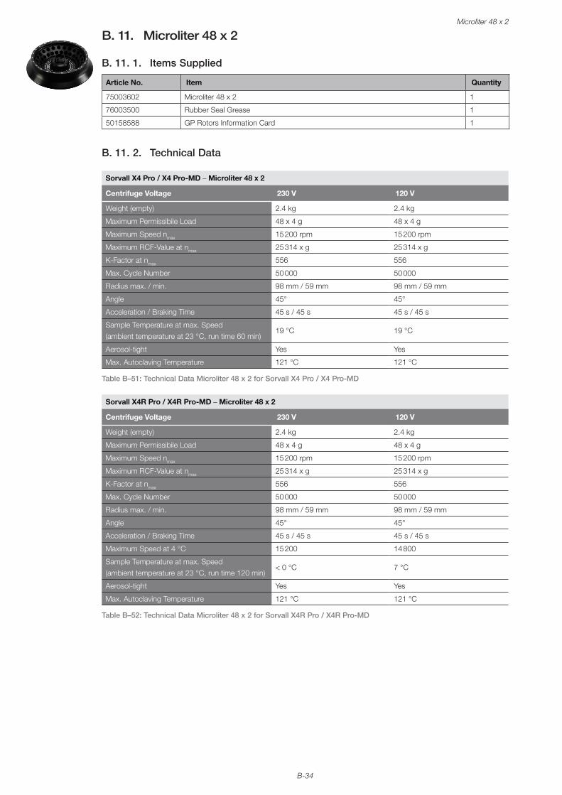
B-34
Microliter 48 x 2
B. 11. Microliter 48 x 2
B. 11. 1. Items Supplied
Article No. Item Quantity
75003602 Microliter 48 x 2 1
76003500 Rubber Seal Grease 1
50158588 GP Rotors Information Card 1
B. 11. 2. Technical Data
Sorvall X4 Pro / X4 Pro-MD – Microliter 48 x 2
Centrifuge Voltage 230 V 120 V
Weight (empty) 2.4 kg 2.4 kg
Maximum Permissibile Load 48 x 4 g 48 x 4 g
Maximum Speed nmax 15 200 rpm 15 200 rpm
Maximum RCF-Value at nmax 25 314 x g 25 314 x g
K-Factor at nmax 556 556
Max. Cycle Number 50 000 50 000
Radius max. / min. 98 mm / 59 mm 98 mm / 59 mm
Angle 45° 45°
Acceleration / Braking Time 45 s / 45 s 45 s / 45 s
Sample Temperature at max. Speed (ambient temperature at 23 °C, run time 60 min)
19 °C 19 °C
Aerosol-tight Yes Yes
Max. Autoclaving Temperature 121 °C 121 °C
Table B–51: Technical Data Microliter 48 x 2 for Sorvall X4 Pro / X4 Pro-MD
Sorvall X4R Pro / X4R Pro-MD – Microliter 48 x 2
Centrifuge Voltage 230 V 120 V
Weight (empty) 2.4 kg 2.4 kg
Maximum Permissibile Load 48 x 4 g 48 x 4 g
Maximum Speed nmax 15 200 rpm 15 200 rpm
Maximum RCF-Value at nmax 25 314 x g 25 314 x g
K-Factor at nmax 556 556
Max. Cycle Number 50 000 50 000
Radius max. / min. 98 mm / 59 mm 98 mm / 59 mm
Angle 45° 45°
Acceleration / Braking Time 45 s / 45 s 45 s / 45 s
Maximum Speed at 4 °C 15 200 14 800
Sample Temperature at max. Speed (ambient temperature at 23 °C, run time 120 min)
< 0 °C 7 °C
Aerosol-tight Yes Yes
Max. Autoclaving Temperature 121 °C 121 °C
Table B–52: Technical Data Microliter 48 x 2 for Sorvall X4R Pro / X4R Pro-MD
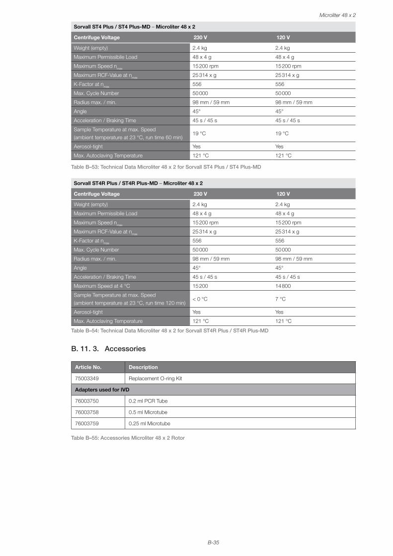
B-35
Microliter 48 x 2
Sorvall ST4 Plus / ST4 Plus-MD – Microliter 48 x 2
Centrifuge Voltage 230 V 120 V
Weight (empty) 2.4 kg 2.4 kg
Maximum Permissibile Load 48 x 4 g 48 x 4 g
Maximum Speed nmax 15 200 rpm 15 200 rpm
Maximum RCF-Value at nmax 25 314 x g 25 314 x g
K-Factor at nmax 556 556
Max. Cycle Number 50 000 50 000
Radius max. / min. 98 mm / 59 mm 98 mm / 59 mm
Angle 45° 45°
Acceleration / Braking Time 45 s / 45 s 45 s / 45 s
Sample Temperature at max. Speed (ambient temperature at 23 °C, run time 60 min)
19 °C 19 °C
Aerosol-tight Yes Yes
Max. Autoclaving Temperature 121 °C 121 °C
Table B–53: Technical Data Microliter 48 x 2 for Sorvall ST4 Plus / ST4 Plus-MD
Sorvall ST4R Plus / ST4R Plus-MD – Microliter 48 x 2
Centrifuge Voltage 230 V 120 V
Weight (empty) 2.4 kg 2.4 kg
Maximum Permissibile Load 48 x 4 g 48 x 4 g
Maximum Speed nmax 15 200 rpm 15 200 rpm
Maximum RCF-Value at nmax 25 314 x g 25 314 x g
K-Factor at nmax 556 556
Max. Cycle Number 50 000 50 000
Radius max. / min. 98 mm / 59 mm 98 mm / 59 mm
Angle 45° 45°
Acceleration / Braking Time 45 s / 45 s 45 s / 45 s
Maximum Speed at 4 °C 15 200 14 800
Sample Temperature at max. Speed (ambient temperature at 23 °C, run time 120 min)
< 0 °C 7 °C
Aerosol-tight Yes Yes
Max. Autoclaving Temperature 121 °C 121 °C
Table B–54: Technical Data Microliter 48 x 2 for Sorvall ST4R Plus / ST4R Plus-MD
B. 11. 3. Accessories
Article No. Description
75003349 Replacement O-ring Kit
Adapters used for IVD
76003750 0.2 ml PCR Tube
76003758 0.5 ml Microtube
76003759 0.25 ml Microtube
Table B–55: Accessories Microliter 48 x 2 Rotor
B-36
Microliter 48 x 2
B. 11. 4. Biocontainment Certificate
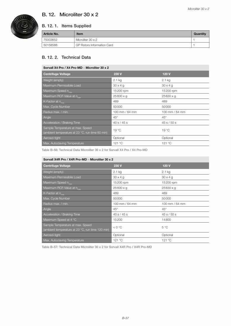
B-37
Microliter 30 x 2
B. 12. Microliter 30 x 2
B. 12. 1. Items Supplied
Article No. Item Quantity
75003652 Microliter 30 x 2 1
50158588 GP Rotors Information Card 1
B. 12. 2. Technical Data
Sorvall X4 Pro / X4 Pro-MD – Microliter 30 x 2
Centrifuge Voltage 230 V 120 V
Weight (empty) 2.1 kg 2.1 kg
Maximum Permissibile Load 30 x 4 g 30 x 4 g
Maximum Speed nmax 15 200 rpm 15 200 rpm
Maximum RCF-Value at nmax 25 830 x g 25 830 x g
K-Factor at nmax 489 489
Max. Cycle Number 50 000 50 000
Radius max. / min. 100 mm / 64 mm 100 mm / 64 mm
Angle 45° 45°
Acceleration / Braking Time 40 s / 45 s 45 s / 50 s
Sample Temperature at max. Speed (ambient temperature at 23 °C, run time 60 min)
19 °C 19 °C
Aerosol-tight Optional Optional
Max. Autoclaving Temperature 121 °C 121 °C
Table B–56: Technical Data Microliter 30 x 2 for Sorvall X4 Pro / X4 Pro-MD
Sorvall X4R Pro / X4R Pro-MD – Microliter 30 x 2
Centrifuge Voltage 230 V 120 V
Weight (empty) 2.1 kg 2.1 kg
Maximum Permissibile Load 30 x 4 g 30 x 4 g
Maximum Speed nmax 15 200 rpm 15 200 rpm
Maximum RCF-Value at nmax 25 830 x g 25 830 x g
K-Factor at nmax 489 489
Max. Cycle Number 50 000 50 000
Radius max. / min. 100 mm / 64 mm 100 mm / 64 mm
Angle 45° 45°
Acceleration / Braking Time 40 s / 45 s 45 s / 50 s
Maximum Speed at 4 °C 15 200 14 800
Sample Temperature at max. Speed (ambient temperature at 23 °C, run time 120 min)
< 0 °C 5 °C
Aerosol-tight Optional Optional
Max. Autoclaving Temperature 121 °C 121 °C
Table B–57: Technical Data Microliter 30 x 2 for Sorvall X4R Pro / X4R Pro-MD

B-38
Microliter 30 x 2
Sorvall ST4 Plus / ST4 Plus-MD – Microliter 30 x 2
Centrifuge Voltage 230 V 120 V
Weight (empty) 2.1 kg 2.1 kg
Maximum Permissibile Load 30 x 4 g 30 x 4 g
Maximum Speed nmax 15 200 rpm 15 200 rpm
Maximum RCF-Value at nmax 25 830 x g 25 830 x g
K-Factor at nmax 489 489
Max. Cycle Number 50 000 50 000
Radius max. / min. 100 mm / 64 mm 100 mm / 64 mm
Angle 45° 45°
Acceleration / Braking Time 40 s / 45 s 45 s / 50 s
Sample Temperature at max. Speed (ambient temperature at 23 °C, run time 60 min)
19 °C 19 °C
Aerosol-tight Optional Optional
Max. Autoclaving Temperature 121 °C 121 °C
Table B–58: Technical Data Microliter 30 x 2 for Sorvall ST4 Plus / ST4 Plus-MD
Sorvall ST4R Plus / ST4R Plus-MD – Microliter 30 x 2
Centrifuge Voltage 230 V 120 V
Weight (empty) 2.1 kg 2.1 kg
Maximum Permissibile Load 30 x 4 g 30 x 4 g
Maximum Speed nmax 15 200 rpm 15 200 rpm
Maximum RCF-Value at nmax 25 830 x g 25 830 x g
K-Factor at nmax 489 489
Max. Cycle Number 50 000 50 000
Radius max. / min. 100 mm / 64 mm 100 mm / 64 mm
Angle 45° 45°
Acceleration / Braking Time 40 s / 45 s 45 s / 50 s
Maximum Speed at 4 °C 15 200 14 800
Sample Temperature at max. Speed (ambient temperature at 23 °C, run time 120 min)
< 0 °C 5 °C
Aerosol-tight Optional Optional
Max. Autoclaving Temperature 121 °C 121 °C
Table B–59: Technical Data Microliter 30 x 2 for Sorvall ST4R Plus / ST4R Plus-MD
B. 12. 3. Accessories
Article No. Description
75003349 Replacement O-ring Kit
Adapters used for IVD
76003750 0.2 ml PCR Tube
76003758 0.5 ml Microtube
76003759 0.25 ml Microtube
Table B–60: Accessories Microliter 30 x 2 Rotor
B-39
Microliter 30 x 2
B. 12. 4. Biocontainment Certificate
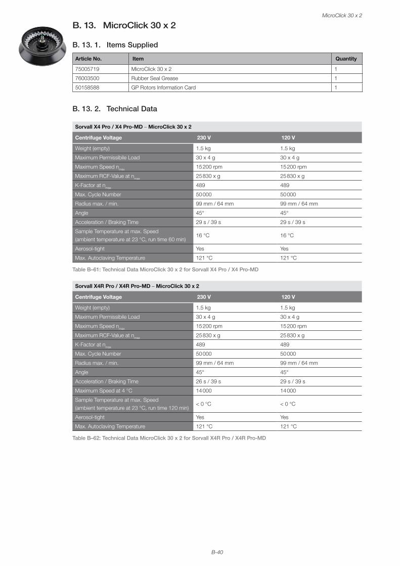
B-40
MicroClick 30 x 2
B. 13. MicroClick 30 x 2
B. 13. 1. Items Supplied
Article No. Item Quantity
75005719 MicroClick 30 x 2 1
76003500 Rubber Seal Grease 1
50158588 GP Rotors Information Card 1
B. 13. 2. Technical Data
Sorvall X4 Pro / X4 Pro-MD – MicroClick 30 x 2
Centrifuge Voltage 230 V 120 V
Weight (empty) 1.5 kg 1.5 kg
Maximum Permissibile Load 30 x 4 g 30 x 4 g
Maximum Speed nmax 15 200 rpm 15 200 rpm
Maximum RCF-Value at nmax 25 830 x g 25 830 x g
K-Factor at nmax 489 489
Max. Cycle Number 50 000 50 000
Radius max. / min. 99 mm / 64 mm 99 mm / 64 mm
Angle 45° 45°
Acceleration / Braking Time 29 s / 39 s 29 s / 39 s
Sample Temperature at max. Speed (ambient temperature at 23 °C, run time 60 min)
16 °C 16 °C
Aerosol-tight Yes Yes
Max. Autoclaving Temperature 121 °C 121 °C
Table B–61: Technical Data MicroClick 30 x 2 for Sorvall X4 Pro / X4 Pro-MD
Sorvall X4R Pro / X4R Pro-MD – MicroClick 30 x 2
Centrifuge Voltage 230 V 120 V
Weight (empty) 1.5 kg 1.5 kg
Maximum Permissibile Load 30 x 4 g 30 x 4 g
Maximum Speed nmax 15 200 rpm 15 200 rpm
Maximum RCF-Value at nmax 25 830 x g 25 830 x g
K-Factor at nmax 489 489
Max. Cycle Number 50 000 50 000
Radius max. / min. 99 mm / 64 mm 99 mm / 64 mm
Angle 45° 45°
Acceleration / Braking Time 26 s / 39 s 29 s / 39 s
Maximum Speed at 4 °C 14 000 14 000
Sample Temperature at max. Speed (ambient temperature at 23 °C, run time 120 min)
< 0 °C < 0 °C
Aerosol-tight Yes Yes
Max. Autoclaving Temperature 121 °C 121 °C
Table B–62: Technical Data MicroClick 30 x 2 for Sorvall X4R Pro / X4R Pro-MD

B-41
MicroClick 30 x 2
Sorvall ST4 Plus / ST4 Plus-MD – MicroClick 30 x 2
Centrifuge Voltage 230 V 120 V
Weight (empty) 1.5 kg 1.5 kg
Maximum Permissibile Load 30 x 4 g 30 x 4 g
Maximum Speed nmax 15 200 rpm 15 200 rpm
Maximum RCF-Value at nmax 25 830 x g 25 830 x g
K-Factor at nmax 489 489
Max. Cycle Number 50 000 50 000
Radius max. / min. 99 mm / 64 mm 99 mm / 64 mm
Angle 45° 45°
Acceleration / Braking Time 29 s / 39 s 29 s / 39 s
Sample Temperature at max. Speed (ambient temperature at 23 °C, run time 60 min)
16 °C 16 °C
Aerosol-tight Yes Yes
Max. Autoclaving Temperature 121 °C 121 °C
Table B–63: Technical Data MicroClick 30 x 2 for Sorvall ST4 Plus / ST4 Plus-MD
Sorvall ST4R Plus / ST4R Plus-MD – MicroClick 30 x 2
Centrifuge Voltage 230 V 120 V
Weight (empty) 1.5 kg 1.5 kg
Maximum Permissibile Load 30 x 4 g 30 x 4 g
Maximum Speed nmax 15 200 rpm 15 200 rpm
Maximum RCF-Value at nmax 25 830 x g 25 830 x g
K-Factor at nmax 489 489
Max. Cycle Number 50 000 50 000
Radius max. / min. 99 mm / 64 mm 99 mm / 64 mm
Angle 45° 45°
Acceleration / Braking Time 29 s / 39 s 29 s / 39 s
Maximum Speed at 4 °C 14 000 14 000
Sample Temperature at max. Speed (ambient temperature at 23 °C, run time 120 min)
< 0 °C 1 °C
Aerosol-tight Yes Yes
Max. Autoclaving Temperature 121 °C 121 °C
Table B–64: Technical Data MicroClick 30 x 2 for Sorvall ST4R Plus
B. 13. 3. Accessories
Article No. Description
75005726 Replacement O-ring Kit
Adapters used for IVD
76003750 0.2 ml PCR Tube
76003758 0.5 ml Microtube
76003759 0.25 ml Microtube
Table B–65: Accessories MicroClick 30 x 2 Rotor
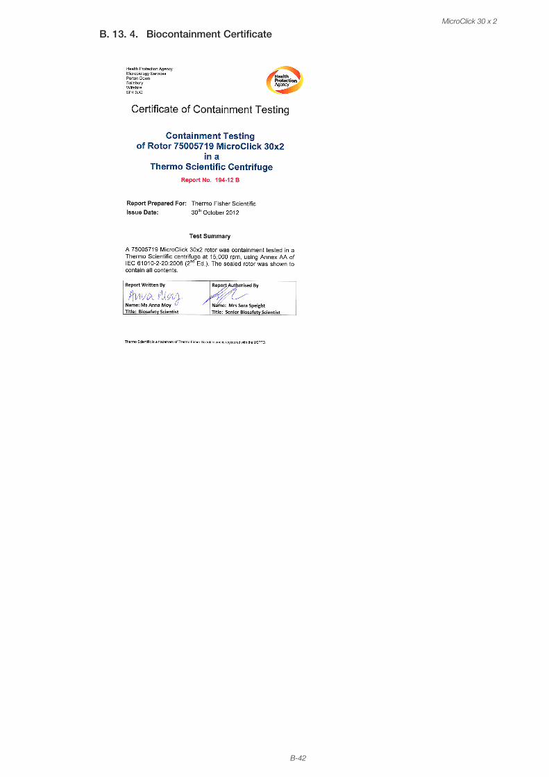
B-42
MicroClick 30 x 2
B. 13. 4. Biocontainment Certificate
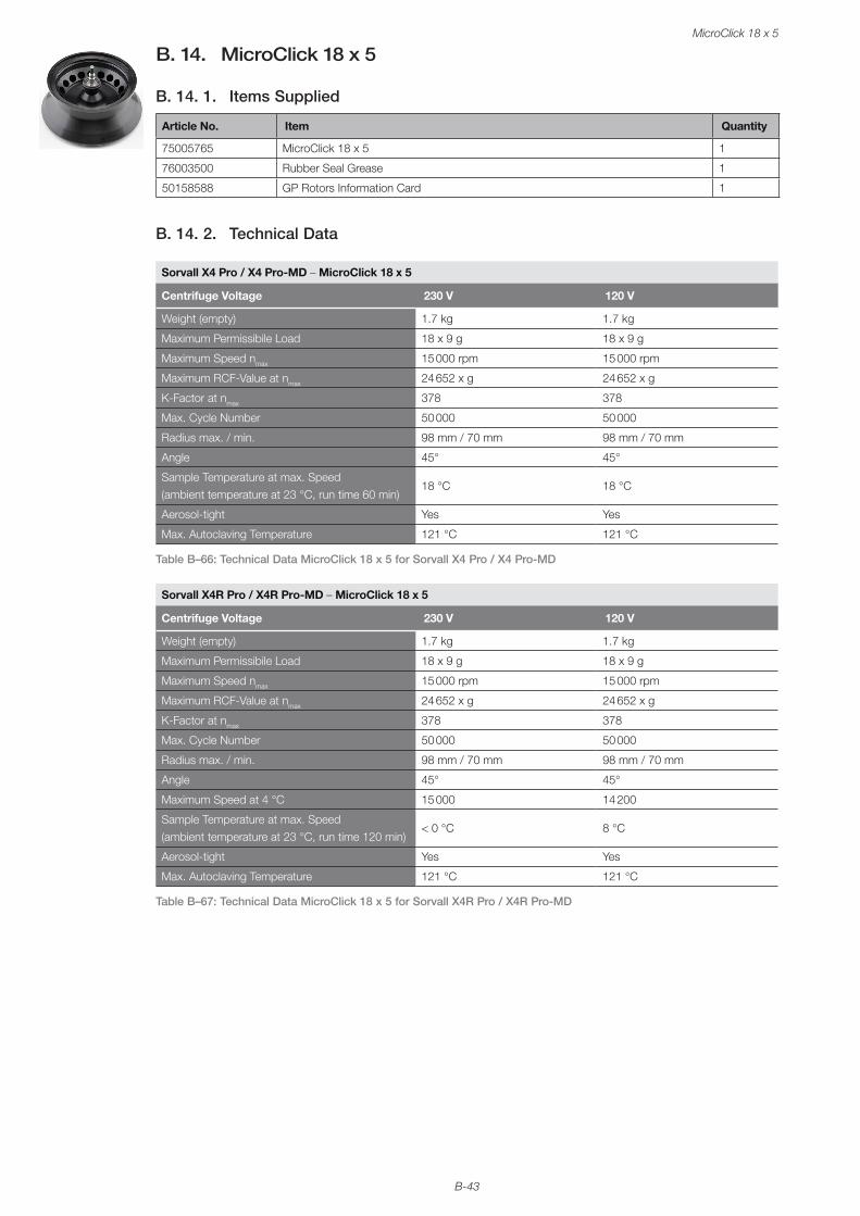
B-43
MicroClick 18 x 5
B. 14. MicroClick 18 x 5
B. 14. 1. Items Supplied
Article No. Item Quantity
75005765 MicroClick 18 x 5 1
76003500 Rubber Seal Grease 1
50158588 GP Rotors Information Card 1
B. 14. 2. Technical Data
Sorvall X4 Pro / X4 Pro-MD – MicroClick 18 x 5
Centrifuge Voltage 230 V 120 V
Weight (empty) 1.7 kg 1.7 kg
Maximum Permissibile Load 18 x 9 g 18 x 9 g
Maximum Speed nmax 15 000 rpm 15 000 rpm
Maximum RCF-Value at nmax 24 652 x g 24 652 x g
K-Factor at nmax 378 378
Max. Cycle Number 50 000 50 000
Radius max. / min. 98 mm / 70 mm 98 mm / 70 mm
Angle 45° 45°
Sample Temperature at max. Speed (ambient temperature at 23 °C, run time 60 min)
18 °C 18 °C
Aerosol-tight Yes Yes
Max. Autoclaving Temperature 121 °C 121 °C
Table B–66: Technical Data MicroClick 18 x 5 for Sorvall X4 Pro / X4 Pro-MD
Sorvall X4R Pro / X4R Pro-MD – MicroClick 18 x 5
Centrifuge Voltage 230 V 120 V
Weight (empty) 1.7 kg 1.7 kg
Maximum Permissibile Load 18 x 9 g 18 x 9 g
Maximum Speed nmax 15 000 rpm 15 000 rpm
Maximum RCF-Value at nmax 24 652 x g 24 652 x g
K-Factor at nmax 378 378
Max. Cycle Number 50 000 50 000
Radius max. / min. 98 mm / 70 mm 98 mm / 70 mm
Angle 45° 45°
Maximum Speed at 4 °C 15 000 14 200
Sample Temperature at max. Speed (ambient temperature at 23 °C, run time 120 min)
< 0 °C 8 °C
Aerosol-tight Yes Yes
Max. Autoclaving Temperature 121 °C 121 °C
Table B–67: Technical Data MicroClick 18 x 5 for Sorvall X4R Pro / X4R Pro-MD

B-44
MicroClick 18 x 5
Sorvall ST4 Plus / ST4 Plus-MD – MicroClick 18 x 5
Centrifuge Voltage 230 V 120 V
Weight (empty) 1.7 kg 1.7 kg
Maximum Permissibile Load 18 x 9 g 18 x 9 g
Maximum Speed nmax 15 000 rpm 15 000 rpm
Maximum RCF-Value at nmax 24 652 x g 24 652 x g
K-Factor at nmax 378 378
Max. Cycle Number 50 000 50 000
Radius max. / min. 98 mm / 70 mm 98 mm / 70 mm
Angle 45° 45°
Acceleration / Braking Time 45 s / 45 s 45 s / 45 s
Sample Temperature at max. Speed (ambient temperature at 23 °C, run time 60 min)
18 °C 18 °C
Aerosol-tight Yes Yes
Max. Autoclaving Temperature 121 °C 121 °C
Table B–68: Technical Data MicroClick 18 x 5 for Sorvall ST4 Plus / ST4 Plus-MD
Sorvall ST4R Plus / ST4R Plus-MD – MicroClick 18 x 5
Centrifuge Voltage 230 V 120 V
Weight (empty) 1.7 kg 1.7 kg
Maximum Permissibile Load 18 x 9 g 18 x 9 g
Maximum Speed nmax 15 000 rpm
Maximum RCF-Value at nmax 24 652 x g
K-Factor at nmax 378
Max. Cycle Number 50 000 50 000
Radius max. / min. 98 mm / 70 mm 98 mm / 70 mm
Angle 45° 45°
Acceleration / Braking Time 45 s / 45 s 45 s / 45 s
Maximum Speed at 4 °C 15 000 14 200
Sample Temperature at max. Speed (ambient temperature at 23 °C, run time 120 min)
< 0 °C 8 °C
Aerosol-tight Yes Yes
Max. Autoclaving Temperature 121 °C 121 °C
Table B–69: Technical Data MicroClick 18 x 5 for Sorvall ST4R Plus / ST4R Plus-MD
B. 14. 3. Accessories
Article No. Description
75005726 Replacement O-ring Kit
Adapters used for IVD
75005756 1.5/2 ml Microtube
Table B–70: Accessories MicroClick 18 x 5 Rotor
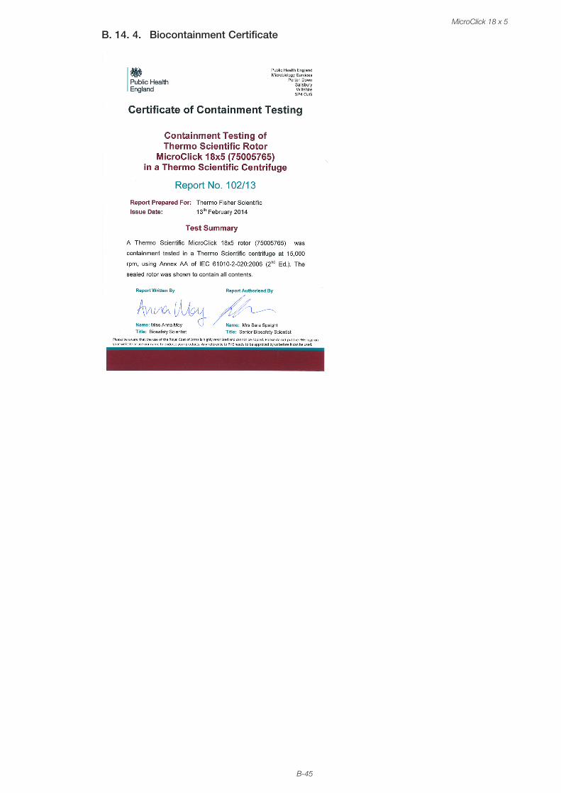
B-45
MicroClick 18 x 5
B. 14. 4. Biocontainment Certificate
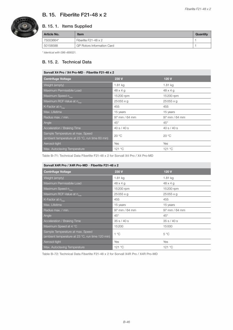
B-46
Fiberlite F21-48 x 2
B. 15. Fiberlite F21-48 x 2
B. 15. 1. Items Supplied
Article No. Item Quantity
75003664* Fiberlite F21-48 x 2 1
50158588 GP Rotors Information Card 1
* Identical with 096-489021.
B. 15. 2. Technical Data
Sorvall X4 Pro / X4 Pro-MD – Fiberlite F21-48 x 2
Centrifuge Voltage 230 V 120 V
Weight (empty) 1.81 kg 1.81 kg
Maximum Permissibile Load 48 x 4 g 48 x 4 g
Maximum Speed nmax 15 200 rpm 15 200 rpm
Maximum RCF-Value at nmax 25 055 x g 25 055 x g
K-Factor at nmax 455 455
Max. Lifetime 15 years 15 years
Radius max. / min. 97 mm / 64 mm 97 mm / 64 mm
Angle 45° 45°
Acceleration / Braking Time 40 s / 40 s 40 s / 40 s
Sample Temperature at max. Speed (ambient temperature at 23 °C, run time 60 min)
20 °C 20 °C
Aerosol-tight Yes Yes
Max. Autoclaving Temperature 121 °C 121 °C
Table B–71: Technical Data Fiberlite F21-48 x 2 for Sorvall X4 Pro / X4 Pro-MD
Sorvall X4R Pro / X4R Pro-MD – Fiberlite F21-48 x 2
Centrifuge Voltage 230 V 120 V
Weight (empty) 1.81 kg 1.81 kg
Maximum Permissibile Load 48 x 4 g 48 x 4 g
Maximum Speed nmax 15 200 rpm 15 200 rpm
Maximum RCF-Value at nmax 25 055 x g 25 055 x g
K-Factor at nmax 455 455
Max. Lifetime 15 years 15 years
Radius max. / min. 97 mm / 64 mm 97 mm / 64 mm
Angle 45° 45°
Acceleration / Braking Time 35 s / 40 s 35 s / 40 s
Maximum Speed at 4 °C 15 200 15 000
Sample Temperature at max. Speed (ambient temperature at 23 °C, run time 120 min)
1 °C 5 °C
Aerosol-tight Yes Yes
Max. Autoclaving Temperature 121 °C 121 °C
Table B–72: Technical Data Fiberlite F21-48 x 2 for Sorvall X4R Pro / X4R Pro-MD

B-47
Fiberlite F21-48 x 2
Sorvall ST4 Plus / ST4 Plus-MD – Fiberlite F21-48 x 2
Centrifuge Voltage 230 V 120 V
Weight (empty) 1.81 kg 1.81 kg
Maximum Permissibile Load 48 x 4 g 48 x 4 g
Maximum Speed nmax 15 200 rpm 15 200 rpm
Maximum RCF-Value at nmax 25 055 x g 25 055 x g
K-Factor at nmax 455 455
Max. Lifetime 15 years 15 years
Radius max. / min. 97 mm / 64 mm 97 mm / 64 mm
Angle 45° 45°
Acceleration / Braking Time 40 s / 40 s 40 s / 40 s
Sample Temperature at max. Speed (ambient temperature at 23 °C, run time 60 min)
20 °C 20 °C
Aerosol-tight Yes Yes
Max. Autoclaving Temperature 121 °C 121 °C
Table B–73: Technical Data Fiberlite F21-48 x 2 for Sorvall ST4 Plus / ST4 Plus-MD
Sorvall ST4R Plus / ST4R Plus-MD – Fiberlite F21-48 x 2
Centrifuge Voltage 230 V 120 V
Weight (empty) 1.81 kg 1.81 kg
Maximum Permissibile Load 48 x 4 g 48 x 4 g
Maximum Speed nmax 15 200 rpm 15 200 rpm
Maximum RCF-Value at nmax 25 055 x g 25 055 x g
K-Factor at nmax 455 455
Max. Lifetime 15 years 15 years
Radius max. / min. 97 mm / 64 mm 97 mm / 64 mm
Angle 45° 45°
Acceleration / Braking Time 35 s / 40 s 35 s / 40 s
Maximum Speed at 4 °C 15 200 15 000
Sample Temperature at max. Speed (ambient temperature at 23 °C, run time 120 min)
1 °C 5 °C
Aerosol-tight Yes Yes
Max. Autoclaving Temperature 121 °C 121 °C
Table B–74: Technical Data Fiberlite F21-48 x 2 for Sorvall ST4R Plus / ST4R Plus-MD
B. 15. 3. Accessories
Article No. Description
021-489021 Replacement O-ring Kit
Adapters used for IVD
76003750 0.2 ml PCR Tube
76003758 0.5 ml Microtube
76003759 0.25 ml Microtube
Table B–75: Accessories Fiberlite F21-48 x 2 Rotor
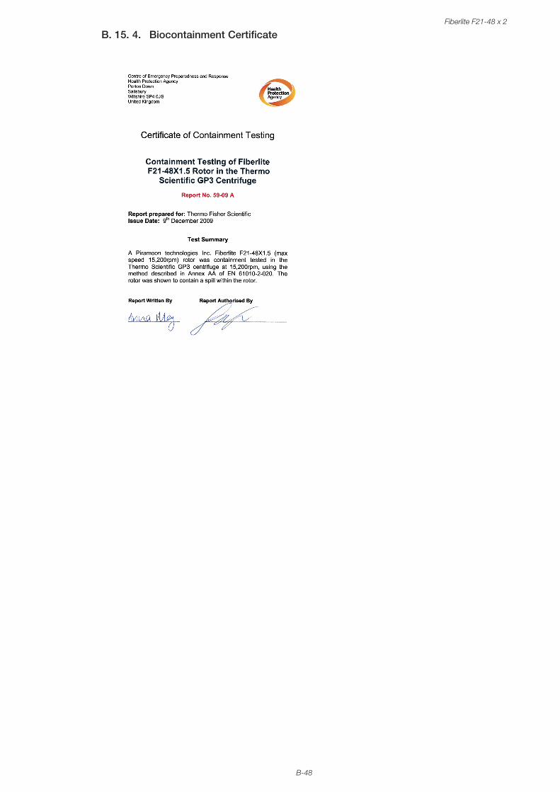
B-48
Fiberlite F21-48 x 2
B. 15. 4. Biocontainment Certificate
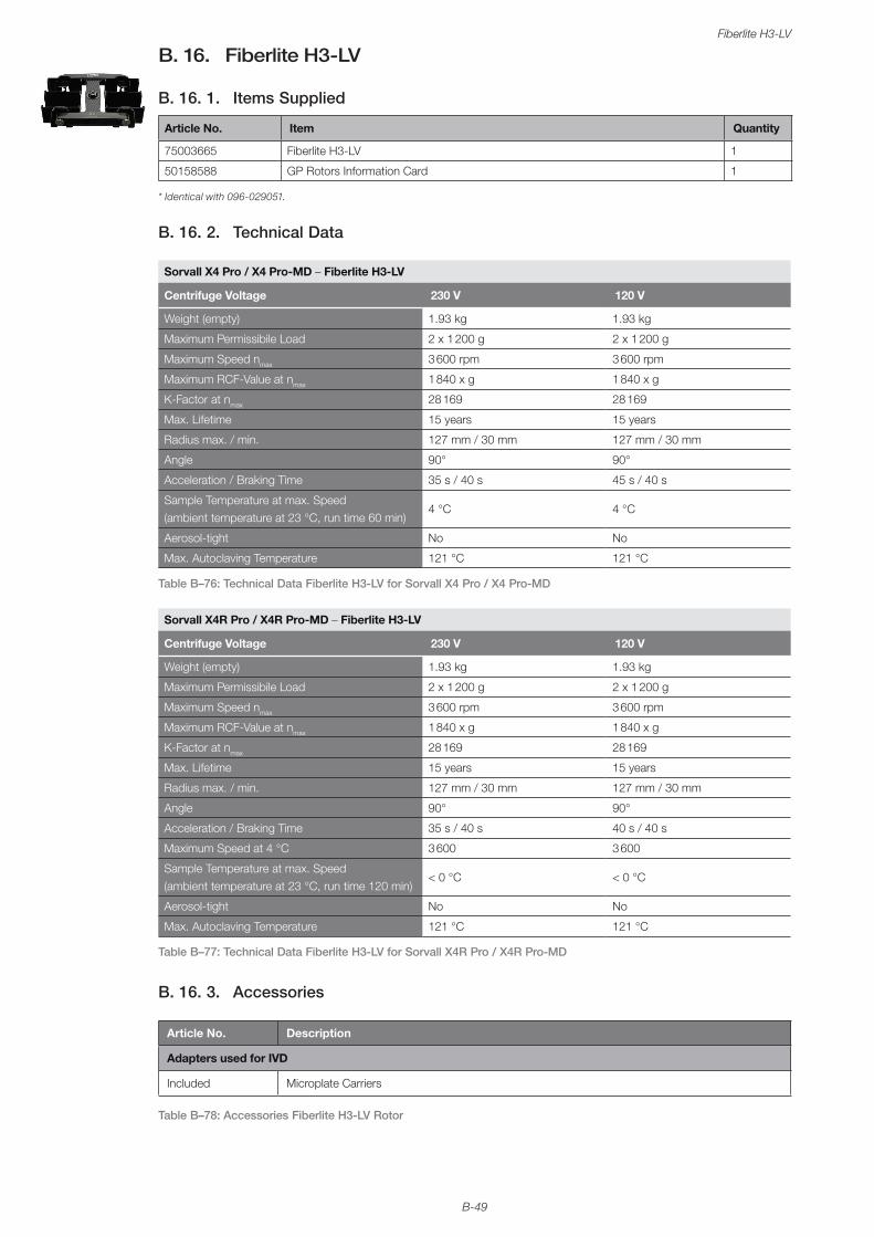
B-49
Fiberlite H3-LV
B. 16. Fiberlite H3-LV
B. 16. 1. Items Supplied
Article No. Item Quantity
75003665 Fiberlite H3-LV 1
50158588 GP Rotors Information Card 1
* Identical with 096-029051.
B. 16. 2. Technical Data
Sorvall X4 Pro / X4 Pro-MD – Fiberlite H3-LV
Centrifuge Voltage 230 V 120 V
Weight (empty) 1.93 kg 1.93 kg
Maximum Permissibile Load 2 x 1 200 g 2 x 1 200 g
Maximum Speed nmax 3 600 rpm 3 600 rpm
Maximum RCF-Value at nmax 1 840 x g 1 840 x g
K-Factor at nmax 28 169 28 169
Max. Lifetime 15 years 15 years
Radius max. / min. 127 mm / 30 mm 127 mm / 30 mm
Angle 90° 90°
Acceleration / Braking Time 35 s / 40 s 45 s / 40 s
Sample Temperature at max. Speed (ambient temperature at 23 °C, run time 60 min)
4 °C 4 °C
Aerosol-tight No No
Max. Autoclaving Temperature 121 °C 121 °C
Table B–76: Technical Data Fiberlite H3-LV for Sorvall X4 Pro / X4 Pro-MD
Sorvall X4R Pro / X4R Pro-MD – Fiberlite H3-LV
Centrifuge Voltage 230 V 120 V
Weight (empty) 1.93 kg 1.93 kg
Maximum Permissibile Load 2 x 1 200 g 2 x 1 200 g
Maximum Speed nmax 3 600 rpm 3 600 rpm
Maximum RCF-Value at nmax 1 840 x g 1 840 x g
K-Factor at nmax 28 169 28 169
Max. Lifetime 15 years 15 years
Radius max. / min. 127 mm / 30 mm 127 mm / 30 mm
Angle 90° 90°
Acceleration / Braking Time 35 s / 40 s 40 s / 40 s
Maximum Speed at 4 °C 3 600 3 600
Sample Temperature at max. Speed (ambient temperature at 23 °C, run time 120 min)
< 0 °C < 0 °C
Aerosol-tight No No
Max. Autoclaving Temperature 121 °C 121 °C
Table B–77: Technical Data Fiberlite H3-LV for Sorvall X4R Pro / X4R Pro-MD
B. 16. 3. Accessories
Article No. Description
Adapters used for IVD
Included Microplate Carriers
Table B–78: Accessories Fiberlite H3-LV Rotor
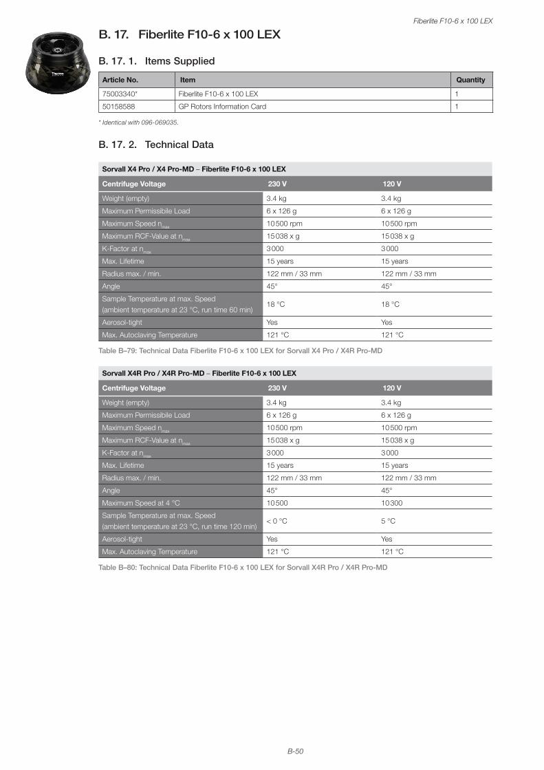
B-50
Fiberlite F10-6 x 100 LEX
B. 17. Fiberlite F10-6 x 100 LEX
B. 17. 1. Items Supplied
Article No. Item Quantity
75003340* Fiberlite F10-6 x 100 LEX 1
50158588 GP Rotors Information Card 1
* Identical with 096-069035.
B. 17. 2. Technical Data
Sorvall X4 Pro / X4 Pro-MD – Fiberlite F10-6 x 100 LEX
Centrifuge Voltage 230 V 120 V
Weight (empty) 3.4 kg 3.4 kg
Maximum Permissibile Load 6 x 126 g 6 x 126 g
Maximum Speed nmax 10 500 rpm 10 500 rpm
Maximum RCF-Value at nmax 15 038 x g 15 038 x g
K-Factor at nmax 3 000 3 000
Max. Lifetime 15 years 15 years
Radius max. / min. 122 mm / 33 mm 122 mm / 33 mm
Angle 45° 45°
Sample Temperature at max. Speed (ambient temperature at 23 °C, run time 60 min)
18 °C 18 °C
Aerosol-tight Yes Yes
Max. Autoclaving Temperature 121 °C 121 °C
Table B–79: Technical Data Fiberlite F10-6 x 100 LEX for Sorvall X4 Pro / X4R Pro-MD
Sorvall X4R Pro / X4R Pro-MD – Fiberlite F10-6 x 100 LEX
Centrifuge Voltage 230 V 120 V
Weight (empty) 3.4 kg 3.4 kg
Maximum Permissibile Load 6 x 126 g 6 x 126 g
Maximum Speed nmax 10 500 rpm 10 500 rpm
Maximum RCF-Value at nmax 15 038 x g 15 038 x g
K-Factor at nmax 3 000 3 000
Max. Lifetime 15 years 15 years
Radius max. / min. 122 mm / 33 mm 122 mm / 33 mm
Angle 45° 45°
Maximum Speed at 4 °C 10 500 10 300
Sample Temperature at max. Speed (ambient temperature at 23 °C, run time 120 min)
< 0 °C 5 °C
Aerosol-tight Yes Yes
Max. Autoclaving Temperature 121 °C 121 °C
Table B–80: Technical Data Fiberlite F10-6 x 100 LEX for Sorvall X4R Pro / X4R Pro-MD
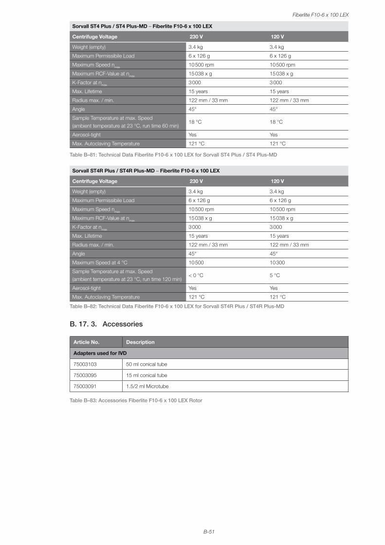
B-51
Fiberlite F10-6 x 100 LEX
Sorvall ST4 Plus / ST4 Plus-MD – Fiberlite F10-6 x 100 LEX
Centrifuge Voltage 230 V 120 V
Weight (empty) 3.4 kg 3.4 kg
Maximum Permissibile Load 6 x 126 g 6 x 126 g
Maximum Speed nmax 10 500 rpm 10 500 rpm
Maximum RCF-Value at nmax 15 038 x g 15 038 x g
K-Factor at nmax 3 000 3 000
Max. Lifetime 15 years 15 years
Radius max. / min. 122 mm / 33 mm 122 mm / 33 mm
Angle 45° 45°
Sample Temperature at max. Speed (ambient temperature at 23 °C, run time 60 min)
18 °C 18 °C
Aerosol-tight Yes Yes
Max. Autoclaving Temperature 121 °C 121 °C
Table B–81: Technical Data Fiberlite F10-6 x 100 LEX for Sorvall ST4 Plus / ST4 Plus-MD
Sorvall ST4R Plus / ST4R Plus-MD – Fiberlite F10-6 x 100 LEX
Centrifuge Voltage 230 V 120 V
Weight (empty) 3.4 kg 3.4 kg
Maximum Permissibile Load 6 x 126 g 6 x 126 g
Maximum Speed nmax 10 500 rpm 10 500 rpm
Maximum RCF-Value at nmax 15 038 x g 15 038 x g
K-Factor at nmax 3 000 3 000
Max. Lifetime 15 years 15 years
Radius max. / min. 122 mm / 33 mm 122 mm / 33 mm
Angle 45° 45°
Maximum Speed at 4 °C 10 500 10 300
Sample Temperature at max. Speed (ambient temperature at 23 °C, run time 120 min)
< 0 °C 5 °C
Aerosol-tight Yes Yes
Max. Autoclaving Temperature 121 °C 121 °C
Table B–82: Technical Data Fiberlite F10-6 x 100 LEX for Sorvall ST4R Plus / ST4R Plus-MD
B. 17. 3. Accessories
Article No. Description
Adapters used for IVD
75003103 50 ml conical tube
75003095 15 ml conical tube
75003091 1.5/2 ml Microtube
Table B–83: Accessories Fiberlite F10-6 x 100 LEX Rotor
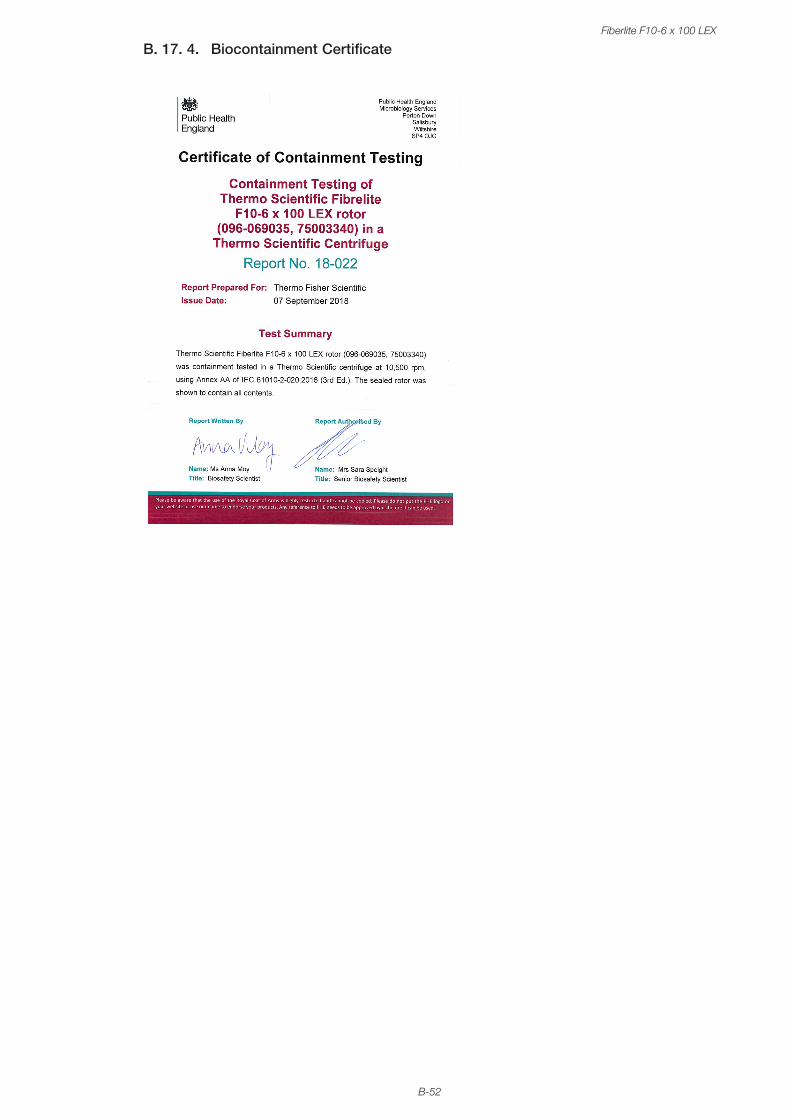
B-52
Fiberlite F10-6 x 100 LEX
B. 17. 4. Biocontainment Certificate
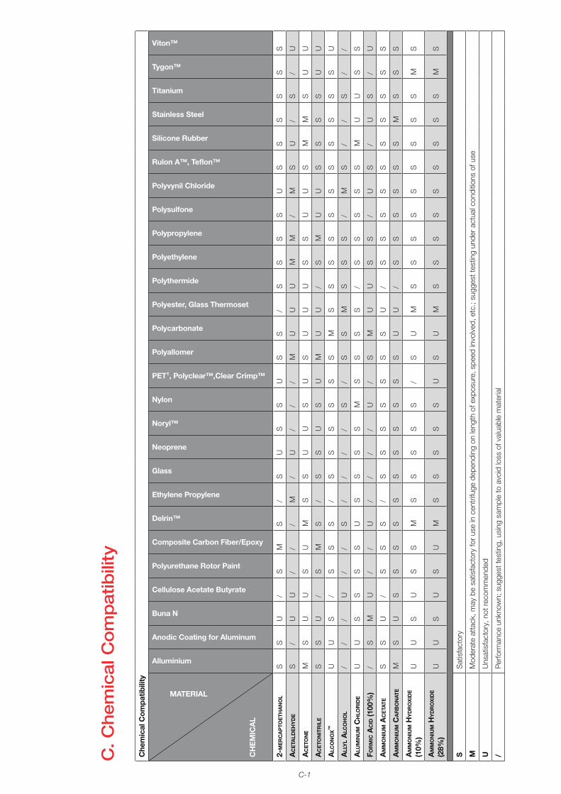
C-1
C. C
hem
ical
Co
mp
atib
ility
Che
mic
al C
ompa
tibili
ty
MATERIAL
CH
EM
ICA
L
Alluminium
Anodic Coating for Aluminum
Buna N
Cellulose Acetate Butyrate
Polyurethane Rotor Paint
Composite Carbon Fiber/Epoxy
Delrin™
Ethylene Propylene
Glass
Neoprene
Noryl™
Nylon
PET¹, Polyclear™,Clear Crimp™
Polyallomer
Polycarbonate
Polyester, Glass Thermoset
Polythermide
Polyethylene
Polypropylene
Polysulfone
Polyvynil Chloride
Rulon A™, Teflon™
Silicone Rubber
Stainless Steel
Titanium
Tygon™
Viton™
2-m
er
ca
pto
eth
an
ol
ss
u/
sm
s/
su
ss
us
s/
ss
ss
us
ss
ss
s
ac
eta
lde
hy
de
s/
uu
//
/m
/u
//
/m
uu
um
m/
ms
u/
s/
u
ac
eto
ne
ms
uu
su
ms
su
us
us
uu
us
su
us
mm
su
u
ac
eto
nit
ril
es
su
/s
ms
/s
su
su
mu
u/
sm
uu
ss
ss
uu
alc
on
ox
™u
us
/s
ss
/s
ss
ss
sm
ss
ss
ss
ss
ss
su
all
yl
alc
oh
ol
//
/u
//
s/
//
/s
/s
sm
ss
s/
ms
//
s/
/
alu
min
um
ch
lor
ide
uu
ss
ss
us
ss
sm
ss
ss
/s
ss
ss
mu
us
s
For
mic
ac
id (1
00%
)/
sm
u/
/u
//
//
u/
sm
uu
ss
/u
s/
us
/u
am
mo
niu
m a
ce
tate
ss
u/
ss
s/
ss
ss
ss
su
/s
ss
ss
ss
ss
s
am
mo
niu
m c
ar
bo
nat
em
su
ss
ss
ss
ss
ss
su
u/
ss
ss
ss
ms
ss
am
mo
niu
m h
yd
ro
xid
e
(10%
)u
us
us
sm
ss
ss
s/
su
ms
ss
ss
ss
ss
ms
am
mo
niu
m h
yd
ro
xid
e
(28%
)u
us
us
um
ss
ss
su
su
ms
ss
ss
ss
ss
ms
SS
atis
fact
ory
mM
oder
ate
atta
ck, m
ay b
e sa
tisfa
ctor
y fo
r use
in c
entr
ifuge
dep
endi
ng o
n le
ngth
of e
xpos
ure,
spe
ed in
volv
ed, e
tc.;
sugg
est t
estin
g un
der a
ctua
l con
ditio
ns o
f use
uU
nsat
isfa
ctor
y, n
ot re
com
men
ded
/Pe
rform
ance
unk
now
n; s
ugge
st te
stin
g, u
sing
sam
ple
to a
void
loss
of v
alua
ble
mat
eria
l
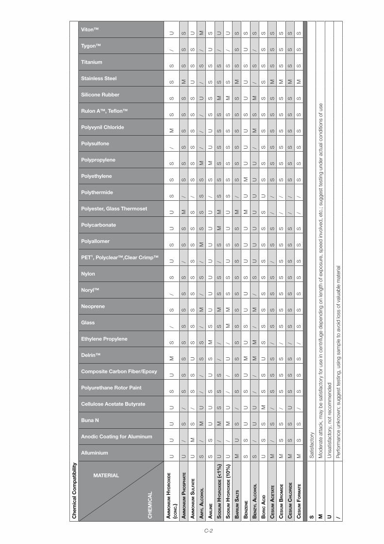
C-2
Che
mic
al C
ompa
tibili
ty
MATERIAL
CH
EM
ICA
L
Alluminium
Anodic Coating for Aluminum
Buna N
Cellulose Acetate Butyrate
Polyurethane Rotor Paint
Composite Carbon Fiber/Epoxy
Delrin™
Ethylene Propylene
Glass
Neoprene
Noryl™
Nylon
PET¹, Polyclear™,Clear Crimp™
Polyallomer
Polycarbonate
Polyester, Glass Thermoset
Polythermide
Polyethylene
Polypropylene
Polysulfone
Polyvynil Chloride
Rulon A™, Teflon™
Silicone Rubber
Stainless Steel
Titanium
Tygon™
Viton™
am
mo
niu
m h
yd
ro
xid
e
(co
nc.)
uu
uu
su
ms
/s
/s
us
uu
ss
s/
ms
ss
s/
u
am
mo
niu
m p
ho
sp
hat
eu
/s
/s
ss
ss
ss
s/
ss
m/
ss
ss
ss
ms
ss
am
mo
niu
m s
ulF
ate
um
s/
ss
us
ss
ss
ss
ss
/s
ss
ss
su
ss
u
am
yl
alc
oh
ol
s/
mu
//
ss
/m
/s
/m
ss
ss
m/
//
u/
s/
m
an
ilin
es
su
us
us
ms
uu
uu
uu
u/
sm
uu
ss
ss
us
so
diu
m h
yd
ro
xid
e (<
1%)
u/
ms
ss
//
sm
ss
/s
mm
ss
ss
ss
ms
s/
u
so
diu
m h
yd
ro
xid
e (1
0%)
u/
mu
//
u/
mm
ss
us
uu
ss
ss
ss
ms
s/
u
ba
riu
m s
alt
sm
us
/s
ss
ss
ss
ss
ss
m/
ss
ss
ss
ms
ss
be
nz
en
es
su
us
um
us
uu
su
uu
mu
mu
uu
su
us
us
be
nz
yl
alc
oh
ol
s/
uu
//
mm
/m
/s
uu
uu
uu
u/
ms
m/
s/
s
bo
ric
ac
idu
ss
ms
su
ss
ss
ss
ss
su
ss
ss
ss
ss
ss
ce
siu
m a
ce
tate
m/
s/
ss
s/
ss
ss
/s
s/
/s
ss
ss
sm
ss
s
ce
siu
m b
ro
mid
em
ss
/s
ss
/s
ss
ss
ss
//
ss
ss
ss
ms
ss
ce
siu
m c
hlo
rid
em
ss
us
ss
/s
ss
ss
ss
//
ss
ss
ss
ms
ss
ce
siu
m F
or
mat
em
ss
/s
ss
/s
ss
ss
ss
//
ss
ss
ss
ms
ss
SS
atis
fact
ory
mM
oder
ate
atta
ck, m
ay b
e sa
tisfa
ctor
y fo
r use
in c
entr
ifuge
dep
endi
ng o
n le
ngth
of e
xpos
ure,
spe
ed in
volv
ed, e
tc.;
sugg
est t
estin
g un
der a
ctua
l con
ditio
ns o
f use
uU
nsat
isfa
ctor
y, n
ot re
com
men
ded
/Pe
rform
ance
unk
now
n; s
ugge
st te
stin
g, u
sing
sam
ple
to a
void
loss
of v
alua
ble
mat
eria
l
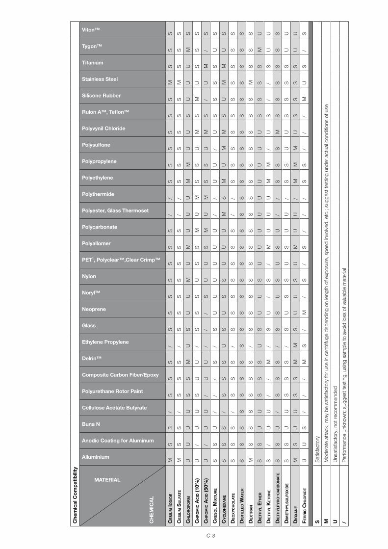
C-3
Che
mic
al C
ompa
tibili
ty
MATERIAL
CH
EM
ICA
L
Alluminium
Anodic Coating for Aluminum
Buna N
Cellulose Acetate Butyrate
Polyurethane Rotor Paint
Composite Carbon Fiber/Epoxy
Delrin™
Ethylene Propylene
Glass
Neoprene
Noryl™
Nylon
PET¹, Polyclear™,Clear Crimp™
Polyallomer
Polycarbonate
Polyester, Glass Thermoset
Polythermide
Polyethylene
Polypropylene
Polysulfone
Polyvynil Chloride
Rulon A™, Teflon™
Silicone Rubber
Stainless Steel
Titanium
Tygon™
Viton™
ce
siu
m io
did
em
ss
/s
ss
/s
ss
ss
ss
//
ss
ss
ss
ms
ss
ce
siu
m s
ulF
ate
ms
s/
ss
s/
ss
ss
ss
s/
/s
ss
ss
sm
ss
s
ch
lor
oFo
rm
uu
uu
ss
mu
su
um
um
uu
um
mu
us
uu
um
s
ch
ro
mic
ac
id (1
0%)
u/
uu
su
u/
ss
su
ss
mu
ms
su
ms
mu
ss
s
ch
ro
mic
ac
id (5
0%)
u/
uu
/u
u/
//
su
us
mu
ms
su
ms
/u
m/
s
cr
es
ol
mix
tur
es
su
//
/s
/s
uu
uu
uu
//
uu
/u
ss
ss
us
cy
clo
he
xa
ne
ss
s/
ss
su
su
ss
uu
um
sm
um
ms
um
mu
s
de
ox
yc
ho
late
ss
s/
ss
s/
ss
ss
ss
s/
/s
ss
ss
ss
ss
s
dis
till
ed W
ate
rs
ss
ss
ss
ss
ss
ss
ss
ss
ss
ss
ss
ss
ss
de
xtr
an
ms
ss
ss
s/
ss
ss
ss
ss
ss
ss
ss
sm
ss
s
die
thy
l e
the
rs
su
us
ss
us
uu
su
uu
uu
uu
uu
ss
ss
mu
die
thy
l K
eto
ne
s/
uu
//
m/
su
/s
/m
uu
um
m/
us
//
su
u
die
thy
lpy
ro-c
ar
bo
nat
es
su
/s
ss
/s
su
su
su
//
ss
sm
ss
ss
ss
dim
eth
yls
ulF
ox
ide
ss
uu
ss
s/
su
ss
us
uu
/s
su
us
ss
su
u
dio
xa
ne
ms
uu
ss
mm
su
us
um
uu
/m
mm
us
ss
su
u
Fer
ric
ch
lor
ide
uu
s/
//
ms
/m
/s
/s
//
/s
s/
//
mu
s/
s
SS
atis
fact
ory
mM
oder
ate
atta
ck, m
ay b
e sa
tisfa
ctor
y fo
r use
in c
entr
ifuge
dep
endi
ng o
n le
ngth
of e
xpos
ure,
spe
ed in
volv
ed, e
tc.;
sugg
est t
estin
g un
der a
ctua
l con
ditio
ns o
f use
uU
nsat
isfa
ctor
y, n
ot re
com
men
ded
/Pe
rform
ance
unk
now
n; s
ugge
st te
stin
g, u
sing
sam
ple
to a
void
loss
of v
alua
ble
mat
eria
l
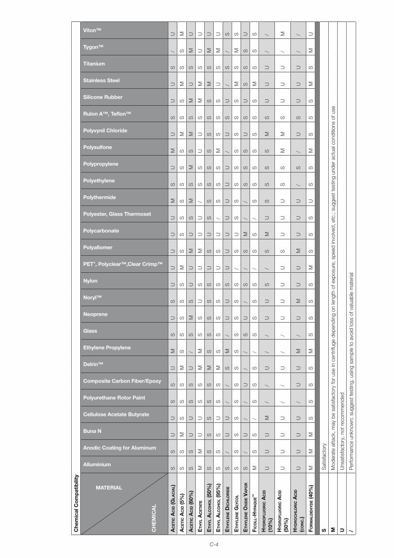
C-4
Che
mic
al C
ompa
tibili
ty
MATERIAL
CH
EM
ICA
L
Alluminium
Anodic Coating for Aluminum
Buna N
Cellulose Acetate Butyrate
Polyurethane Rotor Paint
Composite Carbon Fiber/Epoxy
Delrin™
Ethylene Propylene
Glass
Neoprene
Noryl™
Nylon
PET¹, Polyclear™,Clear Crimp™
Polyallomer
Polycarbonate
Polyester, Glass Thermoset
Polythermide
Polyethylene
Polypropylene
Polysulfone
Polyvynil Chloride
Rulon A™, Teflon™
Silicone Rubber
Stainless Steel
Titanium
Tygon™
Viton™
ac
eti
c a
cid
(Gla
cia
l)s
su
us
su
ms
us
uu
uu
um
su
mu
su
us
/u
ac
eti
c a
cid
(5%
)s
sm
ss
sm
ss
ss
sm
ss
ss
ss
sm
ss
ms
sm
ac
eti
c a
cid
(60%
)s
su
us
su
/s
ms
uu
mu
sm
sm
sm
sm
us
mu
eth
yl
ac
eta
tem
mu
us
sm
ms
su
su
mu
u/
ss
uu
sm
ms
uu
eth
yl
alc
oh
ol
(50%
)s
ss
ss
sm
ss
ss
su
su
ss
ss
ss
ss
ms
mu
eth
yl
alc
oh
ol
(95%
)s
ss
us
sm
ss
ss
su
su
/s
ss
ms
ss
us
mu
eth
yle
ne d
ich
lor
ide
s/
uu
//
sm
/u
us
uu
uu
uu
u/
us
u/
s/
s
eth
yle
ne G
lyc
ol
ss
ss
ss
ss
ss
ss
/s
us
ss
ss
ss
sm
sm
s
eth
yle
ne o
xid
e V
ap
or
s/
u/
/u
//
su
/s
/s
m/
/s
ss
us
us
ss
u
Fic
oll
-hy
paq
ue
™m
ss
/s
ss
/s
ss
s/
ss
/s
ss
ss
ss
ms
ss
hy
dr
oFl
uo
ric
ac
id
(10%
)u
uu
m/
/u
//
uu
s/
sm
us
ss
sm
su
uu
//
hy
dr
oFl
uo
ric
ac
id
(50%
)u
uu
u/
/u
//
uu
uu
su
uu
ss
mm
su
uu
/m
hy
dr
oc
hlo
ric
ac
id
(co
nc.)
uu
uu
/u
um
/u
mu
um
uu
u/
s/
us
uu
u/
/
For
ma
lde
hy
de (4
0%)
mm
ms
ss
sm
ss
ss
ms
ss
us
sm
ss
sm
sm
u
SS
atis
fact
ory
mM
oder
ate
atta
ck, m
ay b
e sa
tisfa
ctor
y fo
r use
in c
entr
ifuge
dep
endi
ng o
n le
ngth
of e
xpos
ure,
spe
ed in
volv
ed, e
tc.;
sugg
est t
estin
g un
der a
ctua
l con
ditio
ns o
f use
uU
nsat
isfa
ctor
y, n
ot re
com
men
ded
/Pe
rform
ance
unk
now
n; s
ugge
st te
stin
g, u
sing
sam
ple
to a
void
loss
of v
alua
ble
mat
eria
l
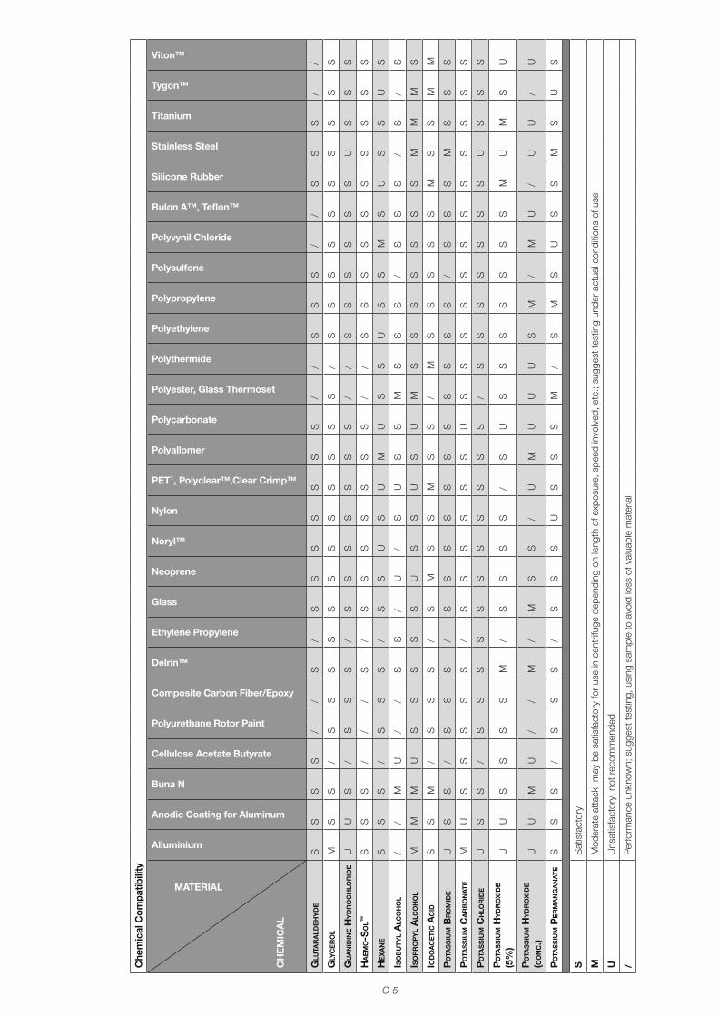
C-5
Che
mic
al C
ompa
tibili
ty
MATERIAL
CH
EM
ICA
L
Alluminium
Anodic Coating for Aluminum
Buna N
Cellulose Acetate Butyrate
Polyurethane Rotor Paint
Composite Carbon Fiber/Epoxy
Delrin™
Ethylene Propylene
Glass
Neoprene
Noryl™
Nylon
PET¹, Polyclear™,Clear Crimp™
Polyallomer
Polycarbonate
Polyester, Glass Thermoset
Polythermide
Polyethylene
Polypropylene
Polysulfone
Polyvynil Chloride
Rulon A™, Teflon™
Silicone Rubber
Stainless Steel
Titanium
Tygon™
Viton™
Glu
tar
ald
eh
yd
es
ss
s/
/s
/s
ss
ss
ss
//
ss
s/
/s
ss
//
Gly
ce
ro
lm
ss
/s
ss
ss
ss
ss
ss
s/
ss
ss
ss
ss
ss
Gu
an
idin
e h
yd
ro
ch
lor
ide
uu
s/
ss
s/
ss
ss
ss
s/
/s
ss
ss
su
ss
s
ha
em
o-s
ol™
ss
s/
//
s/
ss
ss
ss
s/
/s
ss
ss
ss
ss
s
he
xa
ne
ss
s/
ss
s/
ss
us
um
us
su
ss
ms
us
su
s
iso
bu
tyl
alc
oh
ol
//
mu
//
ss
/u
/s
us
sm
ss
s/
ss
s/
s/
s
iso
pr
op
yl
alc
oh
ol
mm
mu
ss
ss
su
ss
us
um
ss
ss
ss
sm
mm
s
iod
oa
ce
tic a
cid
ss
m/
ss
s/
sm
ss
ms
s/
ms
ss
ss
ms
sm
m
po
tas
siu
m b
ro
mid
eu
ss
/s
ss
/s
ss
ss
ss
ss
ss
/s
ss
ms
ss
po
tas
siu
m c
ar
bo
nat
em
us
ss
ss
/s
ss
ss
su
ss
ss
ss
ss
ss
ss
po
tas
siu
m c
hlo
rid
eu
ss
/s
ss
ss
ss
ss
ss
/s
ss
ss
ss
us
ss
po
tas
siu
m h
yd
ro
xid
e
(5%
)u
us
ss
sm
/s
ss
s/
su
ss
ss
ss
sm
um
su
po
tas
siu
m h
yd
ro
xid
e
(co
nc.)
uu
mu
//
m/
ms
s/
um
uu
us
m/
mu
/u
u/
u
po
tas
siu
m p
er
ma
nG
an
ate
ss
s/
ss
s/
ss
su
ss
sm
/s
ms
us
sm
su
s
SS
atis
fact
ory
mM
oder
ate
atta
ck, m
ay b
e sa
tisfa
ctor
y fo
r use
in c
entr
ifuge
dep
endi
ng o
n le
ngth
of e
xpos
ure,
spe
ed in
volv
ed, e
tc.;
sugg
est t
estin
g un
der a
ctua
l con
ditio
ns o
f use
uU
nsat
isfa
ctor
y, n
ot re
com
men
ded
/Pe
rform
ance
unk
now
n; s
ugge
st te
stin
g, u
sing
sam
ple
to a
void
loss
of v
alua
ble
mat
eria
l
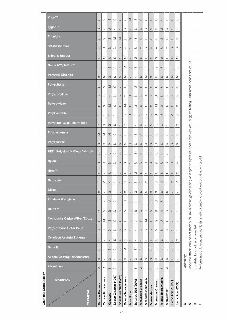
C-6
Che
mic
al C
ompa
tibili
ty
MATERIAL
CH
EM
ICA
L
Alluminium
Anodic Coating for Aluminum
Buna N
Cellulose Acetate Butyrate
Polyurethane Rotor Paint
Composite Carbon Fiber/Epoxy
Delrin™
Ethylene Propylene
Glass
Neoprene
Noryl™
Nylon
PET¹, Polyclear™,Clear Crimp™
Polyallomer
Polycarbonate
Polyester, Glass Thermoset
Polythermide
Polyethylene
Polypropylene
Polysulfone
Polyvynil Chloride
Rulon A™, Teflon™
Silicone Rubber
Stainless Steel
Titanium
Tygon™
Viton™
ca
lciu
m c
hlo
rid
em
us
ss
ss
ss
ss
ss
sm
s/
ss
ss
ss
ms
ss
ca
lciu
m h
yp
oc
hlo
rit
em
/u
/s
mm
s/
m/
s/
sm
s/
ss
sm
sm
us
/s
Ke
ro
se
ne
ss
s/
ss
su
sm
us
um
ms
/m
mm
ss
us
su
s
so
diu
m c
hlo
rid
e (1
0%)
s/
ss
ss
ss
//
/s
ss
ss
/s
ss
s/
ss
m/
s
so
diu
m c
hlo
rid
e (s
at'd
)u
/s
us
ss
//
//
ss
ss
s/
ss
/s
/s
sm
/s
ca
rb
on t
etr
ac
hlo
rid
eu
um
ss
um
us
uu
su
mu
ss
mm
sm
mm
mu
ss
aq
ua r
eG
iau
/u
u/
/u
//
//
/u
uu
uu
uu
//
//
/s
/m
so
luti
on 5
55 (2
0%)
ss
s/
//
s/
ss
ss
ss
s/
/s
ss
/s
ss
ss
s
ma
Gn
es
ium
ch
lor
ide
ms
s/
ss
ss
ss
ss
ss
ss
ss
ss
ss
sm
ss
s
me
rc
ap
toa
ce
tic a
cid
us
u/
sm
s/
sm
su
uu
u/
su
us
ms
us
ss
s
me
thy
l a
lco
ho
ls
ss
us
sm
ss
ss
su
su
ms
ss
ss
ss
ms
mu
me
thy
len
e c
hlo
rid
eu
uu
um
ss
us
uu
su
uu
uu
mu
uu
ss
mu
su
me
thy
l e
thy
l K
eto
ne
ss
uu
ss
ms
su
us
us
uu
us
su
us
ss
su
u
me
triz
am
ide
™m
ss
/s
ss
/s
ss
s/
ss
//
ss
ss
ss
ms
ss
lac
tic a
cid
(100
%)
//
s/
//
//
/m
su
/s
ss
ms
s/
ms
ms
s/
s
lac
tic a
cid
(20%
)/
/s
s/
//
//
ms
m/
ss
ss
ss
sm
sm
ss
/s
SS
atis
fact
ory
mM
oder
ate
atta
ck, m
ay b
e sa
tisfa
ctor
y fo
r use
in c
entr
ifuge
dep
endi
ng o
n le
ngth
of e
xpos
ure,
spe
ed in
volv
ed, e
tc.;
sugg
est t
estin
g un
der a
ctua
l con
ditio
ns o
f use
uU
nsat
isfa
ctor
y, n
ot re
com
men
ded
/Pe
rform
ance
unk
now
n; s
ugge
st te
stin
g, u
sing
sam
ple
to a
void
loss
of v
alua
ble
mat
eria
l

C-7
Che
mic
al C
ompa
tibili
ty
MATERIAL
CH
EM
ICA
L
Alluminium
Anodic Coating for Aluminum
Buna N
Cellulose Acetate Butyrate
Polyurethane Rotor Paint
Composite Carbon Fiber/Epoxy
Delrin™
Ethylene Propylene
Glass
Neoprene
Noryl™
Nylon
PET¹, Polyclear™,Clear Crimp™
Polyallomer
Polycarbonate
Polyester, Glass Thermoset
Polythermide
Polyethylene
Polypropylene
Polysulfone
Polyvynil Chloride
Rulon A™, Teflon™
Silicone Rubber
Stainless Steel
Titanium
Tygon™
Viton™
n/b
uty
l a
lco
ho
ls
/s
u/
/s
//
sm
/u
sm
ss
ss
mm
sm
/s
/s
n/b
uty
l p
hth
ala
tes
su
/s
ss
/s
uu
su
uu
m/
uu
su
sm
ms
us
n, n
-dim
eth
ylF
or
ma
mid
es
ss
us
ms
/s
su
su
su
u/
ss
uu
sm
ss
su
so
diu
m b
or
ate
ms
ss
ss
ss
ss
su
ss
ss
/s
ss
ss
sm
ss
s
so
diu
m b
ro
mid
eu
ss
/s
ss
/s
ss
ss
ss
s/
ss
ss
ss
ms
ss
so
diu
m c
ar
bo
nat
e (2
%)
mu
ss
ss
ss
ss
ss
ss
us
ss
ss
ss
ss
ss
s
so
diu
m d
od
ec
yl
su
lFat
es
ss
/s
ss
/s
ss
ss
ss
/s
ss
ss
ss
ss
ss
so
diu
m h
yp
oc
hlo
rit
e
(5%
)u
um
ss
mu
ss
ms
ss
ms
ss
sm
ss
sm
us
ms
so
diu
m io
did
em
ss
/s
ss
/s
ss
ss
ss
//
ss
ss
ss
ms
ss
so
diu
m n
itr
ate
ss
s/
ss
ss
ss
ss
ss
ss
/s
ss
ss
us
ss
s
so
diu
m s
ulF
ate
us
s/
ss
ss
ss
ss
ss
ss
ss
ss
ss
sm
ss
s
so
diu
m s
ulF
ide
s/
ss
//
/s
//
/s
ss
uu
//
s/
//
ss
m/
s
so
diu
m s
ulF
ite
ss
s/
ss
ss
ms
ss
ss
sm
/s
ss
ss
ss
ss
s
nic
Ke
l s
alt
su
ss
ss
s/
ss
s/
/s
ss
s/
ss
ss
ss
ms
ss
oil
s (p
etr
ole
um
)s
ss
//
/s
us
ss
su
um
sm
uu
ss
su
ss
ss
SS
atis
fact
ory
mM
oder
ate
atta
ck, m
ay b
e sa
tisfa
ctor
y fo
r use
in c
entr
ifuge
dep
endi
ng o
n le
ngth
of e
xpos
ure,
spe
ed in
volv
ed, e
tc.;
sugg
est t
estin
g un
der a
ctua
l con
ditio
ns o
f use
uU
nsat
isfa
ctor
y, n
ot re
com
men
ded
/Pe
rform
ance
unk
now
n; s
ugge
st te
stin
g, u
sing
sam
ple
to a
void
loss
of v
alua
ble
mat
eria
l
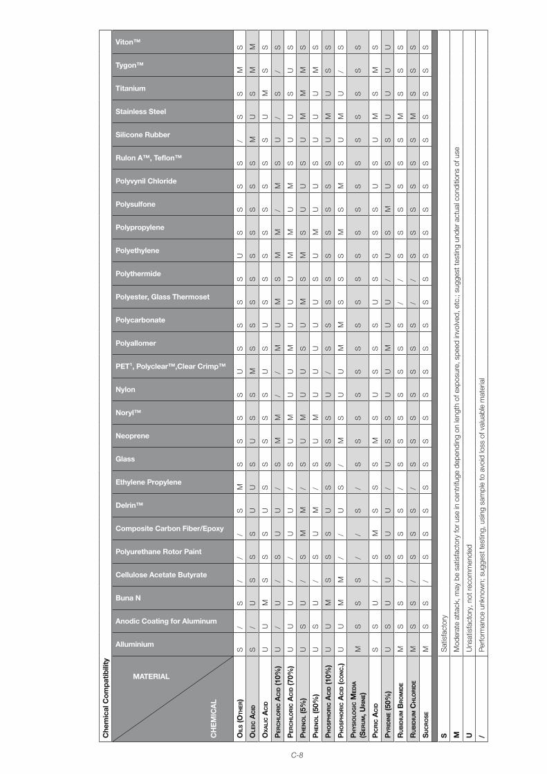
C-8
Che
mic
al C
ompa
tibili
ty
MATERIAL
CH
EM
ICA
L
Alluminium
Anodic Coating for Aluminum
Buna N
Cellulose Acetate Butyrate
Polyurethane Rotor Paint
Composite Carbon Fiber/Epoxy
Delrin™
Ethylene Propylene
Glass
Neoprene
Noryl™
Nylon
PET¹, Polyclear™,Clear Crimp™
Polyallomer
Polycarbonate
Polyester, Glass Thermoset
Polythermide
Polyethylene
Polypropylene
Polysulfone
Polyvynil Chloride
Rulon A™, Teflon™
Silicone Rubber
Stainless Steel
Titanium
Tygon™
Viton™
oil
s (o
the
r)
s/
s/
//
sm
ss
ss
us
ss
su
ss
ss
/s
sm
s
ole
ic a
cid
s/
us
ss
uu
su
ss
ms
ss
ss
ss
ss
mu
sm
m
ox
ali
c a
cid
uu
ms
ss
us
ss
ss
us
us
ss
ss
ss
su
ms
s
pe
rc
hlo
ric
ac
id (1
0%)
u/
u/
su
u/
sm
m/
/m
um
sm
m/
ms
u/
s/
s
pe
rc
hlo
ric
ac
id (7
0%)
uu
u/
/u
u/
su
mu
um
uu
um
mu
ms
uu
su
s
ph
en
ol
(5%
)u
su
/s
mm
/s
um
uu
su
ms
ms
uu
su
mm
ms
ph
en
ol
(50%
)u
su
/s
um
/s
um
uu
uu
us
um
uu
su
uu
ms
ph
os
ph
or
ic a
cid
(10%
)u
um
ss
su
ss
ss
u/
ss
ss
ss
ss
su
mu
ss
ph
os
ph
or
ic a
cid
(co
nc.)
uu
mm
//
us
/m
su
um
ms
ss
ms
ms
um
u/
s
ph
ys
iolo
Gic
me
dia
(s
er
um
, ur
ine)
ms
ss
//
s/
ss
ss
ss
ss
ss
ss
ss
ss
ss
s
pic
ric
ac
ids
su
/s
ms
ss
ms
us
ss
us
ss
su
su
ms
ms
py
rid
ine (5
0%)
us
uu
su
u/
us
su
um
uu
/u
sm
us
su
uu
u
ru
bid
ium
br
om
ide
ms
s/
ss
s/
ss
ss
ss
s/
/s
ss
ss
sm
ss
s
ru
bid
ium
ch
lor
ide
ms
s/
ss
s/
ss
ss
ss
s/
/s
ss
ss
sm
ss
s
su
cr
os
em
ss
/s
ss
ss
ss
ss
ss
ss
ss
ss
ss
ss
ss
SS
atis
fact
ory
mM
oder
ate
atta
ck, m
ay b
e sa
tisfa
ctor
y fo
r use
in c
entr
ifuge
dep
endi
ng o
n le
ngth
of e
xpos
ure,
spe
ed in
volv
ed, e
tc.;
sugg
est t
estin
g un
der a
ctua
l con
ditio
ns o
f use
uU
nsat
isfa
ctor
y, n
ot re
com
men
ded
/Pe
rform
ance
unk
now
n; s
ugge
st te
stin
g, u
sing
sam
ple
to a
void
loss
of v
alua
ble
mat
eria
l
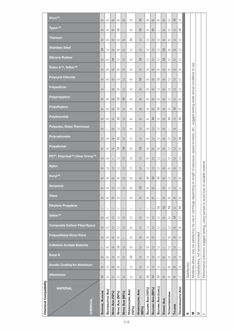
C-9
Che
mic
al C
ompa
tibili
ty
MATERIAL
CH
EM
ICA
L
Alluminium
Anodic Coating for Aluminum
Buna N
Cellulose Acetate Butyrate
Polyurethane Rotor Paint
Composite Carbon Fiber/Epoxy
Delrin™
Ethylene Propylene
Glass
Neoprene
Noryl™
Nylon
PET¹, Polyclear™,Clear Crimp™
Polyallomer
Polycarbonate
Polyester, Glass Thermoset
Polythermide
Polyethylene
Polypropylene
Polysulfone
Polyvynil Chloride
Rulon A™, Teflon™
Silicone Rubber
Stainless Steel
Titanium
Tygon™
Viton™
su
cr
os
e, a
lKa
lin
em
ss
/s
ss
/s
ss
ss
su
ss
ss
ss
ss
ms
ss
su
lFo
sa
lic
yli
c a
cid
uu
ss
ss
s/
ss
su
ss
s/
ss
s/
ss
su
ss
s
nit
ric
ac
id (1
0%)
us
us
su
u/
su
su
/s
ss
ss
ss
ss
ms
ss
s
nit
ric
ac
id (5
0%)
us
um
su
u/
su
su
um
mu
mm
ms
ss
us
sm
s
nit
ric
ac
id (9
5%)
u/
uu
/u
u/
/u
uu
um
uu
uu
mu
us
us
s/
s
hy
dr
oc
hlo
ric
ac
id
(10%
)u
um
ss
su
/s
ss
uu
su
ss
ss
ss
ss
um
ss
hy
dr
oc
hlo
ric
ac
id
(50%
)u
uu
us
uu
/s
ms
uu
mu
us
ss
sm
sm
uu
mm
su
lFu
ric
ac
id (1
0%)
mu
us
su
u/
ss
mu
ss
ss
ss
ss
ss
uu
us
s
su
lFu
ric
ac
id (5
0%)
mu
uu
su
u/
ss
mu
us
uu
ms
ss
ss
uu
um
s
su
lFu
ric
ac
id (c
on
c.)
mu
uu
/u
um
//
mu
us
uu
um
su
ms
uu
u/
s
ste
ar
ic a
cid
s/
s/
//
sm
ss
ss
/s
ss
ss
ss
ss
mm
ss
s
tetr
ah
yd
ro
Fur
an
ss
uu
su
um
su
us
uu
u/
mu
uu
us
us
su
u
tolu
en
es
su
us
sm
us
uu
su
uu
su
mu
uu
su
su
um
tric
hlo
ro
ac
eti
c a
cid
uu
u/
ss
um
su
su
us
m/
ms
su
us
uu
um
u
SS
atis
fact
ory
mM
oder
ate
atta
ck, m
ay b
e sa
tisfa
ctor
y fo
r use
in c
entr
ifuge
dep
endi
ng o
n le
ngth
of e
xpos
ure,
spe
ed in
volv
ed, e
tc.;
sugg
est t
estin
g un
der a
ctua
l con
ditio
ns o
f use
uU
nsat
isfa
ctor
y, n
ot re
com
men
ded
/Pe
rform
ance
unk
now
n; s
ugge
st te
stin
g, u
sing
sam
ple
to a
void
loss
of v
alua
ble
mat
eria
l
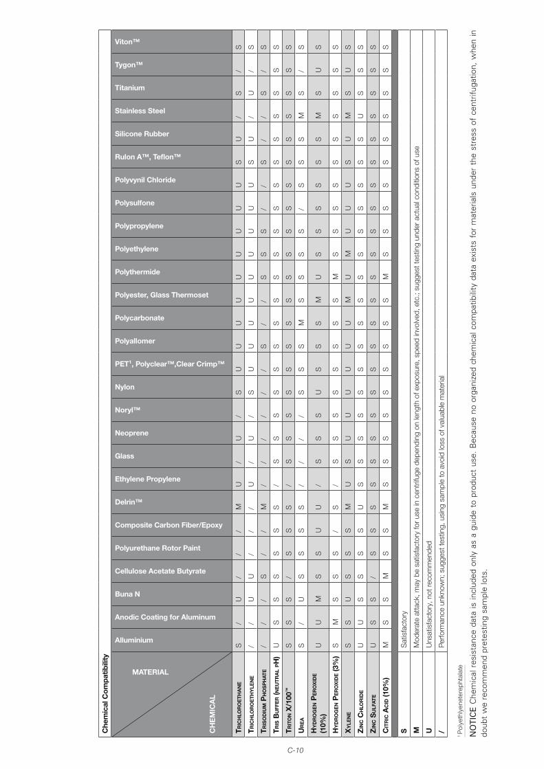
C-10
Che
mic
al C
ompa
tibili
ty
MATERIAL
CH
EM
ICA
L
Alluminium
Anodic Coating for Aluminum
Buna N
Cellulose Acetate Butyrate
Polyurethane Rotor Paint
Composite Carbon Fiber/Epoxy
Delrin™
Ethylene Propylene
Glass
Neoprene
Noryl™
Nylon
PET¹, Polyclear™,Clear Crimp™
Polyallomer
Polycarbonate
Polyester, Glass Thermoset
Polythermide
Polyethylene
Polypropylene
Polysulfone
Polyvynil Chloride
Rulon A™, Teflon™
Silicone Rubber
Stainless Steel
Titanium
Tygon™
Viton™
tric
hlo
ro
eth
an
es
/u
//
/m
u/
u/
su
uu
uu
uu
uu
su
/s
/s
tric
hlo
ro
eth
yle
ne
//
uu
//
/u
/u
/s
uu
uu
uu
uu
us
u/
u/
s
tris
od
ium
ph
os
ph
ate
//
/s
//
m/
//
//
/s
//
ss
s/
/s
//
s/
s
tris
bu
FFe
r (n
eu
tra
l ph
)u
ss
ss
ss
/s
ss
ss
ss
ss
ss
ss
ss
ss
ss
trit
on x
/100
™s
ss
/s
ss
/s
ss
ss
ss
ss
ss
ss
ss
ss
ss
ur
ea
s/
us
ss
s/
//
/s
ss
ms
ss
s/
ss
sm
s/
s
hy
dr
oG
en p
er
ox
ide
(10%
)u
um
ss
uu
/s
ss
us
ss
mu
ss
ss
ss
ms
us
hy
dr
oG
en p
er
ox
ide (3
%)
sm
ss
s/
s/
ss
ss
ss
ss
ms
ss
ss
ss
ss
s
xy
len
es
su
ss
sm
us
uu
uu
uu
mu
mu
uu
su
ms
us
zin
c c
hlo
rid
eu
us
ss
su
ss
ss
ss
ss
ss
ss
ss
ss
us
ss
zin
c s
ulF
ate
us
s/
ss
ss
ss
ss
ss
ss
ss
ss
ss
ss
ss
s
cit
ric
ac
id (1
0%)
ms
sm
ss
ms
ss
ss
ss
ss
ms
ss
ss
ss
ss
s
SS
atis
fact
ory
mM
oder
ate
atta
ck, m
ay b
e sa
tisfa
ctor
y fo
r use
in c
entr
ifuge
dep
endi
ng o
n le
ngth
of e
xpos
ure,
spe
ed in
volv
ed, e
tc.;
sugg
est t
estin
g un
der a
ctua
l con
ditio
ns o
f use
uU
nsat
isfa
ctor
y, n
ot re
com
men
ded
/Pe
rform
ance
unk
now
n; s
ugge
st te
stin
g, u
sing
sam
ple
to a
void
loss
of v
alua
ble
mat
eria
l
1 P
olye
thly
enet
erep
htal
ate
NO
TIC
E C
hem
ical
res
ista
nce
data
is in
clud
ed o
nly
as a
gui
de t
o pr
oduc
t us
e. B
ecau
se n
o or
gani
zed
chem
ical
com
patib
ility
dat
a ex
ists
for
mat
eria
ls u
nder
the
str
ess
of c
entr
ifuga
tion,
whe
n in
do
ubt
we
reco
mm
end
pret
estin
g sa
mpl
e lo
ts.
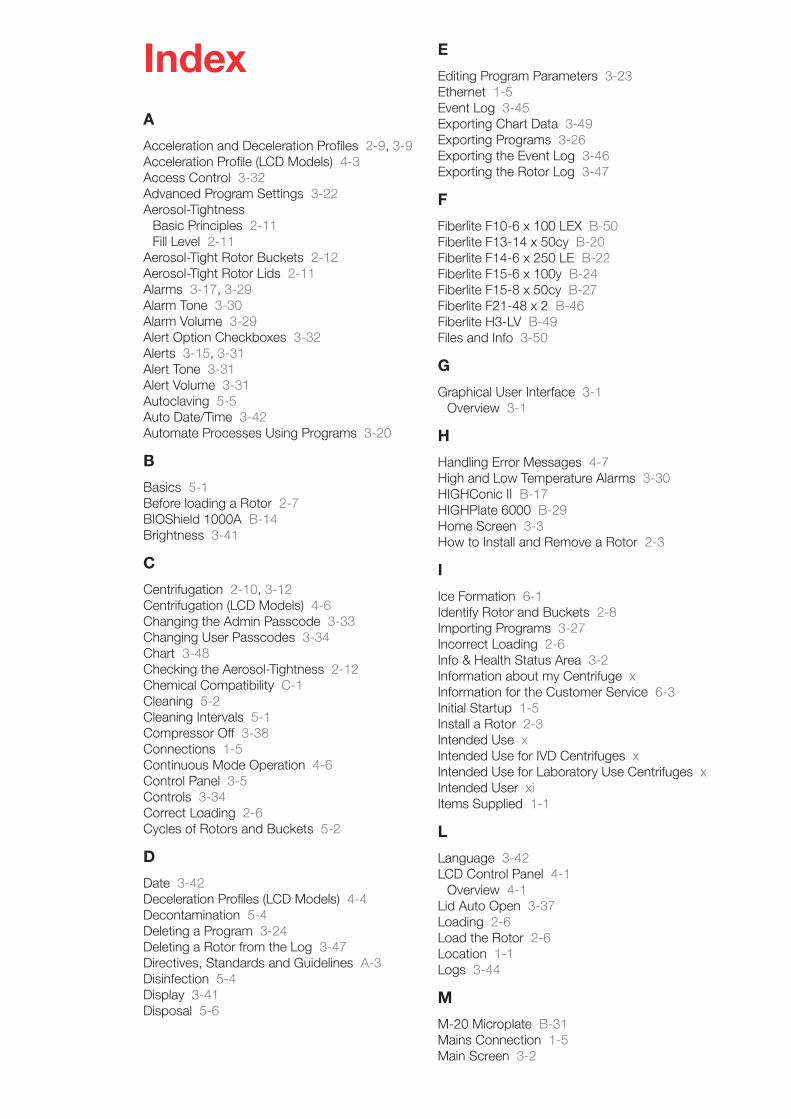
IndexA
Acceleration and Deceleration Profiles 2-9, 3-9Acceleration Profile (LCD Models) 4-3Access Control 3-32Advanced Program Settings 3-22Aerosol-Tightness
Basic Principles 2-11Fill Level 2-11
Aerosol-Tight Rotor Buckets 2-12Aerosol-Tight Rotor Lids 2-11Alarms 3-17, 3-29Alarm Tone 3-30Alarm Volume 3-29Alert Option Checkboxes 3-32Alerts 3-15, 3-31Alert Tone 3-31Alert Volume 3-31Autoclaving 5-5Auto Date/Time 3-42Automate Processes Using Programs 3-20
B
Basics 5-1Before loading a Rotor 2-7BIOShield 1000A B-14Brightness 3-41
C
Centrifugation 2-10, 3-12Centrifugation (LCD Models) 4-6Changing the Admin Passcode 3-33Changing User Passcodes 3-34Chart 3-48Checking the Aerosol-Tightness 2-12Chemical Compatibility C-1Cleaning 5-2Cleaning Intervals 5-1Compressor Off 3-38Connections 1-5Continuous Mode Operation 4-6Control Panel 3-5Controls 3-34Correct Loading 2-6Cycles of Rotors and Buckets 5-2
D
Date 3-42Deceleration Profiles (LCD Models) 4-4Decontamination 5-4Deleting a Program 3-24Deleting a Rotor from the Log 3-47Directives, Standards and Guidelines A-3Disinfection 5-4Display 3-41Disposal 5-6
E
Editing Program Parameters 3-23Ethernet 1-5Event Log 3-45Exporting Chart Data 3-49Exporting Programs 3-26Exporting the Event Log 3-46Exporting the Rotor Log 3-47
F
Fiberlite F10-6 x 100 LEX B-50Fiberlite F13-14 x 50cy B-20Fiberlite F14-6 x 250 LE B-22Fiberlite F15-6 x 100y B-24Fiberlite F15-8 x 50cy B-27Fiberlite F21-48 x 2 B-46Fiberlite H3-LV B-49Files and Info 3-50
G
Graphical User Interface 3-1Overview 3-1
H
Handling Error Messages 4-7High and Low Temperature Alarms 3-30HIGHConic II B-17HIGHPlate 6000 B-29Home Screen 3-3How to Install and Remove a Rotor 2-3
I
Ice Formation 6-1Identify Rotor and Buckets 2-8Importing Programs 3-27Incorrect Loading 2-6Info & Health Status Area 3-2Information about my Centrifuge xInformation for the Customer Service 6-3Initial Startup 1-5Install a Rotor 2-3Intended Use xIntended Use for IVD Centrifuges xIntended Use for Laboratory Use Centrifuges xIntended User xiItems Supplied 1-1
L
Language 3-42LCD Control Panel 4-1
Overview 4-1Lid Auto Open 3-37Loading 2-6Load the Rotor 2-6Location 1-1Logs 3-44
M
M-20 Microplate B-31Mains Connection 1-5Main Screen 3-2
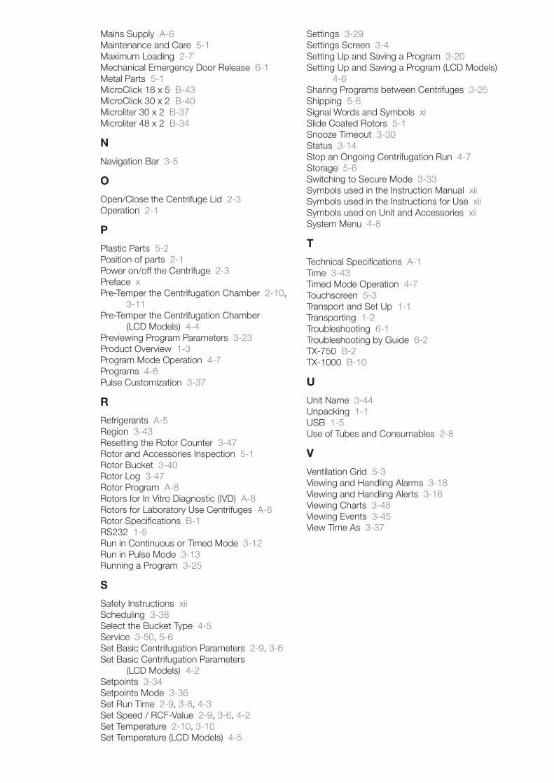
Mains Supply A-6Maintenance and Care 5-1Maximum Loading 2-7Mechanical Emergency Door Release 6-1Metal Parts 5-1MicroClick 18 x 5 B-43MicroClick 30 x 2 B-40Microliter 30 x 2 B-37Microliter 48 x 2 B-34
N
Navigation Bar 3-5
O
Open/Close the Centrifuge Lid 2-3Operation 2-1
P
Plastic Parts 5-2Position of parts 2-1Power on/off the Centrifuge 2-3Preface xPre-Temper the Centrifugation Chamber 2-10,
3-11Pre-Temper the Centrifugation Chamber
(LCD Models) 4-4Previewing Program Parameters 3-23Product Overview 1-3Program Mode Operation 4-7Programs 4-6Pulse Customization 3-37
R
Refrigerants A-5Region 3-43Resetting the Rotor Counter 3-47Rotor and Accessories Inspection 5-1Rotor Bucket 3-40Rotor Log 3-47Rotor Program A-8Rotors for In Vitro Diagnostic (IVD) A-8Rotors for Laboratory Use Centrifuges A-8Rotor Specifications B-1RS232 1-5Run in Continuous or Timed Mode 3-12Run in Pulse Mode 3-13Running a Program 3-25
S
Safety Instructions xiiScheduling 3-38Select the Bucket Type 4-5Service 3-50, 5-6Set Basic Centrifugation Parameters 2-9, 3-6Set Basic Centrifugation Parameters
(LCD Models) 4-2Setpoints 3-34Setpoints Mode 3-36Set Run Time 2-9, 3-8, 4-3Set Speed / RCF-Value 2-9, 3-6, 4-2Set Temperature 2-10, 3-10Set Temperature (LCD Models) 4-5
Settings 3-29Settings Screen 3-4Setting Up and Saving a Program 3-20Setting Up and Saving a Program (LCD Models)
4-6Sharing Programs between Centrifuges 3-25Shipping 5-6Signal Words and Symbols xiSlide Coated Rotors 5-1Snooze Timeout 3-30Status 3-14Stop an Ongoing Centrifugation Run 4-7Storage 5-6Switching to Secure Mode 3-33Symbols used in the Instruction Manual xiiSymbols used in the Instructions for Use xiiSymbols used on Unit and Accessories xiiSystem Menu 4-8
T
Technical Specifications A-1Time 3-43Timed Mode Operation 4-7Touchscreen 5-3Transport and Set Up 1-1Transporting 1-2Troubleshooting 6-1Troubleshooting by Guide 6-2TX-750 B-2TX-1000 B-10
U
Unit Name 3-44Unpacking 1-1USB 1-5Use of Tubes and Consumables 2-8
V
Ventilation Grid 5-3Viewing and Handling Alarms 3-18Viewing and Handling Alerts 3-16Viewing Charts 3-48Viewing Events 3-45View Time As 3-37
thermofisher.com/centrifuge
© 2019 Thermo Fisher Scientific Inc. All rights reserved. All trademarks are the property of Thermo Fisher Scientific Inc. and its subsidiaries unless otherwise indicated.
Delrin, TEFLON, and Viton are registered trademarks of DuPont. Noryl is a registered trademark of SABIC. POLYCLEAR is a registered trade-mark of Hongye CO., Ltd. Hypaque is a registered trademark of Amersham Health As. RULON A and Tygon are registered trademarks of Saint-Gobain Performance Plastics. Alconox is a registered trademark of Alconox. Ficoll is a registered trademark of GE Healthcare. Haemo-Sol is a registered trademark of Haemo-Sol. Triton X-100 is a registered trademark of Sigma-Aldrich Co. LLC. Valox is a registered trademark of General Electric Co. Specifications, terms and pricing are subject to change. Not all products are available in all countries. Please consult your local sales represen-tative for details.Shown pictures within the manual are examples and may differ considering the set parameters and language. Pictures of the user interface within the manual are showing the English version as example.
Australia +61 39757 4300
Austria +43 1 801 40 0
Belgium +32 9 272 54 82
China +800 810 5118, +400 650 5118
France +33 2 2803 2180
Germany national toll free 0800 1 536 376
Germany international +49 6184 90 6000
India toll free +1800 22 8374
India +91 22 6716 2200
Italy +39 02 95059 552
Japan +81 3 5826 1616
Korea +82 2 2023 0600
Netherlands +31 76 579 55 55
New Zealand +64 9 980 6700
Nordic/Baltic/CIS countries +358 10 329 2200
Russia +7 812 703 42 15, +7 495 739 76 41
Singapore +82 2 3420 8700
Spain/Portugal +34 93 223 09 18
Switzerland +41 44 454 12 12
UK/Ireland +44 870 609 9203
USA/Canada +1 866 984 3766
Other Asian Countries +852 3107 7600
Countries not listed +49 6184 90 6000
Thermo Electron LED GmbH
Zweigniederlassung Osterode
Am Kalkberg, 37520 Osterode am Harz
Germany
50158527 is the original instruction manual.
en
Related Documents