ORIGINAL Thermo physical properties of acetone–zinc bromide for using in a low temperature driven absorption refrigeration machine Salman Ajib Ali Karno Received: 30 July 2007 / Accepted: 25 April 2008 / Published online: 14 May 2008 Ó Springer-Verlag 2008 Abstract Thermal physical properties (vapor pressure, density, viscosity, specific heat capacity, specific electrical resistance and specific enthalpy of mixing) of the solution acetone–zinc bromide, which will be used as a working solution in an absorption refrigeration machine, are mea- sured and analyzed. The experimental data were correlated with high accuracy. The required state diagrams (log p, T and h, T) for this solution as well as the log P, h-diagram for the pure acetone are calculated, represented, correlated and discussed. The results indicate that the solution ace- tone-zinc bromide might be suitable as a working solution to operate an absorption refrigeration machine at low temperature. List of symbols c p specific heat capacity (J/kg K) H enthalpy (J) DH enthalpy difference (J) h specific enthalpy (J/kg) Dh specific enthalpy difference (J/kg) m mass (kg) p pressure (N/m 2 ) p s vapor pressure(N/m 2 ) s specific entropy (J/kg K) T temperature (°C, K) v specific volume (m 3 /kg) x absorbent mass fraction (kg ZnBr2 /kg sol )% Greek symbols n refrigerant concentration (kg Ac /kg sol ) l dynamic viscosity (N s/m 2 ) q density (kg/m 3 ) q el specific electrical resistance (Ohm m) Subscripts A absorber Ac acetone C condenser c critical COP coefficient of performance E evaporator G generator s saturated sol solution ZnBr 2 zinc bromide 1 Introduction A working solution for an absorption refrigeration machine consists of a refrigerant and an absorbent. Both substances must have the properties that the refrigerant shall be well absorbed at cooling water temperatures of 20–40°C and separable out of the solution again at desorption tempera- tures higher than 50°C. Furthermore the working solution shall fulfill the most or all the following requirements: • Thermal and physical stability as well as chemical compatibility • Not explosive and no toxicity • Low viscosity • High heat of vaporization • Low specific heat capacity and • Low prices. S. Ajib A. Karno (&) Department of Thermo and Magneto Fluid dynamics, Ilmenau University of Technology, P.O. Box 100565, 98684 Ilmenau, Germany e-mail: [email protected] 123 Heat Mass Transfer (2008) 45:61–70 DOI 10.1007/s00231-008-0409-1

Welcome message from author
This document is posted to help you gain knowledge. Please leave a comment to let me know what you think about it! Share it to your friends and learn new things together.
Transcript
ORIGINAL
Thermo physical properties of acetone–zinc bromide for usingin a low temperature driven absorption refrigeration machine
Salman Ajib Æ Ali Karno
Received: 30 July 2007 / Accepted: 25 April 2008 / Published online: 14 May 2008
� Springer-Verlag 2008
Abstract Thermal physical properties (vapor pressure,
density, viscosity, specific heat capacity, specific electrical
resistance and specific enthalpy of mixing) of the solution
acetone–zinc bromide, which will be used as a working
solution in an absorption refrigeration machine, are mea-
sured and analyzed. The experimental data were correlated
with high accuracy. The required state diagrams (log p, T
and h, T) for this solution as well as the log P, h-diagram
for the pure acetone are calculated, represented, correlated
and discussed. The results indicate that the solution ace-
tone-zinc bromide might be suitable as a working solution
to operate an absorption refrigeration machine at low
temperature.
List of symbols
cp specific heat capacity (J/kg K)
H enthalpy (J)
DH enthalpy difference (J)
h specific enthalpy (J/kg)
Dh specific enthalpy difference (J/kg)
m mass (kg)
p pressure (N/m2)
ps vapor pressure(N/m2)
s specific entropy (J/kg K)
T temperature (�C, K)
v specific volume (m3/kg)
x absorbent mass fraction (kgZnBr2/kgsol) %
Greek symbols
n refrigerant concentration (kgAc/kgsol)
l dynamic viscosity (N s/m2)
q density (kg/m3)
qel specific electrical resistance (Ohm m)
Subscripts
A absorber
Ac acetone
C condenser
c critical
COP coefficient of performance
E evaporator
G generator
s saturated
sol solution
ZnBr2 zinc bromide
1 Introduction
A working solution for an absorption refrigeration machine
consists of a refrigerant and an absorbent. Both substances
must have the properties that the refrigerant shall be well
absorbed at cooling water temperatures of 20–40�C and
separable out of the solution again at desorption tempera-
tures higher than 50�C. Furthermore the working solution
shall fulfill the most or all the following requirements:
• Thermal and physical stability as well as chemical
compatibility
• Not explosive and no toxicity
• Low viscosity
• High heat of vaporization
• Low specific heat capacity and
• Low prices.
S. Ajib � A. Karno (&)
Department of Thermo and Magneto Fluid dynamics,
Ilmenau University of Technology, P.O. Box 100565,
98684 Ilmenau, Germany
e-mail: [email protected]
123
Heat Mass Transfer (2008) 45:61–70
DOI 10.1007/s00231-008-0409-1

In principle, the absorbent must have a high affinity for the
refrigerant and have a low freezing point as well as a higher
boiling point in comparison with the refrigerant so that the
absorbent absorbs the refrigerant well and can be desorbed
easily [1].
The two most common working solutions for absorption
refrigeration machines are: NH3–H2O with ammonia (NH3)
as refrigerant and water (H2O) as absorbent and H2O–LiBr
with water (H2O) as refrigerant and lithium bromide (LiBr)
as absorbent.
The NH3–H2O solution is well suitable for the cold
production under 0�C particularly. The use of flat plate
solar collectors is not sufficient to supply the generator
with a temperature of at least 120�C. Vacuum tube col-
lectors are rather suitable here. In addition, the generator
must be connected with a rectifier so that the water vapour
can be separated from the ammonia vapour. Sierra et al. [2]
have built a laboratory model for an ammonia water
absorption refrigerator. Their machine was driven by a
heating medium with a temperature about 80�C. The
results show that the machine has achieved an evaporation
temperature of less than -2�C at a desorption temperature
of 73�C without problems. However, the reached coeffi-
cient of performance (COP) of the machine, which is
defined as the refrigeration rate over the rate of heat sup-
plied to the generator, was only between 0.24 and 0.28.
Other plants of small capacity with the working solution of
ammonia water were investigated experimentally also in
the works [3–6]. The two of the referenced systems are
diffusion absorption systems, which need a high generation
temperature and have a low COP. The system mentioned in
[3] is with aircooling for the condenser and absorber. The
temperature of cooling water of the system mentioned in
[6] is for absorber 30/35�C and the hot-water temperature
is 147�C. The measured COP amounted 0.2 till 0.3. The
operation of these plants depended upon the outside tem-
peratures and type of the solar collectors with the heating
temperature between 80 and 200�C. The obtained COPs
were between 0.12 and 0.50 at evaporation temperatures of
-18 to 10�C. As a heating source in these plants were
served either high efficient flat plate solar collectors or
vacuum tube collectors. Both collector types are more
expensive compared with the standard economical flat plate
solar collectors. It is known that the higher the needed
work temperature of the flat plate collectors the lower is the
efficiency of such collectors therefore it is prefer to use
work pairs, which can be driven at low generation tem-
perature in the absorption refrigeration machine.
The H2O–LiBr solution needs a desorption temperature
of 75–96�C to be able to operate the absorption refrigera-
tion machine at evaporation temperatures above 4�C
satisfactorily. A disadvantage of the H2O–LiBr solution
would be the possible crystallization of LiBr in the
absorber. To realize the cold production with low tem-
perature drive sources from flat plate solar collectors many
plants were built up and investigated with the working
solution water lithium bromide. These plants were tested
depending upon the cooling water temperatures with a hot
water temperature between 65 and 105�C [7–9]. The results
show that the produced cold is between 6 and 16�C and the
reached COPs are between 0.6 and 0.8.
As above mentioned, a disadvantage of the two common
working solutions is that they require temperature in the
generator of at least 65�C. Therefore we looked for new
working solutions, which may enable to drive the absorp-
tion refrigeration machine with a low drive temperature
(about 55�C).
Within the last 10 years numerous suggestions were
made to find new working solutions [10–13] whose
refrigerant is separable at low-drive temperatures (about
55�C) in the generator and therefore makes use of the flat
plate solar collectors to drive the absorption refrigeration
machine possible.
Pilatowsky et al. [12] have suggested the working solu-
tion monomethylamine–water to run the plant at low
temperatures of 60–80�C. The operating characteristic of
the plant with this new working solution were analyzed and
discussed theoretically, obtaining evaporation temperatures
from -5�C to 10�C and COP from 0.05 to 0.55 at desorp-
tion temperature of 60�C. However, the disadvantage of this
solution is that the COP is low and a rectification for the
vapor produced in the generator is required.
Lucas et al. [13] have suggested the absorbent (LiBr:
CHO2K = 2:1) instead of the pure lithium bromide for the
refrigerant (H2O) to lower the required drive temperature.
Using a simulation model of the system the authors have
calculated the thermal parameters of the machine with this
new working solution. The results have shown that the
machine can produce a cold temperature of 6�C with a
COP of 0.85 at a desorption temperature of 56�C. How-
ever, a disadvantage of the working solution is that the
absorption temperature must be 15�C and the condensation
temperature 46�C for the provided results. These two
temperatures are not practicable in the range of the outside
temperatures. That means one needs heat source for driving
the absorption refrigeration machine and cold source for
supply with cooling water.
We have made many investigations at the working
solution acetone/ZnBr2. Firstly we studied and analyzed
the thermo physical properties of the work pair in the
laboratory [10, 11]. After that we tested the ability to use of
the work pair as work solution in an absorption refrigera-
tion machine with a refrigeration capacity of 10 kW.
The results of investigation have shown that the
absorption refrigeration machine could be driven at tem-
perature up 55�C with a cold-water temperature of 13�C
62 Heat Mass Transfer (2008) 45:61–70
123
and cooling water of 27�C. The refrigeration capacity
amounted ca. 2–3 kW and the COP can be improved to be
in the range of 0.4 till 0.7 [1, 14]. That means there is an
important potential by using of this new working solution
in the low temperature driven absorption refrigeration
machine. The planed application of this working pair is for
air conditioning and for supply with cold water for indus-
trial processes, especially in Europe.
In the following we are going to illustrate the thermo
physical properties of this investigated working solution
(acetone/ZnBr2).
2 Results of experimental investigation
Before using a new working solution in an absorption
refrigeration system, it is very important to know its ther-
modynamic properties and its chemical stability. These
properties have a great influence on the efficiency of the
refrigeration system and on the required operating tem-
peratures. Therefore many experimental investigations
have been realized to determine the thermodynamic prop-
erties of the suggested working solution (acetone–zinc
bromide). The thermo physical properties are measured at
liquid saturated state at the atmospherically pressure or
vapor pressure. The uncertainties for the experiments were
depending on the measured properties and on the measur-
ing devices. More details about that are given in [11].
The experiments of the solubility have shown that the
solubility of the absorbent zinc bromide is very high in the
refrigerant so that solutions can be used for investigation in
a broad range of absorbent mass fractions [30–70%, (kgzinc
bromide/kgsolution)] at the solution temperature of 20�C.
The experiments of dissolubility of acetone from the
solution have shown that at a concentration of 30% of zinc
bromide nearly all of the acetone has been evaporated at a
temperature of 50�C and a pressure of 750 mbar (mea-
suring value). That means that the acetone could be driven
out from the solution at the given conditions. Other
experiment conditions have been investigated (other tem-
perature and other concentrations). The investigation
results are shown in the appendix.
The system acetone–zinc bromide has been tested to
operate as a work solution in an absorption refrigerator at
low temperature and therefore many experiments have
been realized to determine its thermodynamic properties
(density, viscosity, specific heat capacity, specific electrical
resistance, vapor pressure and enthalpy) [10, 11].
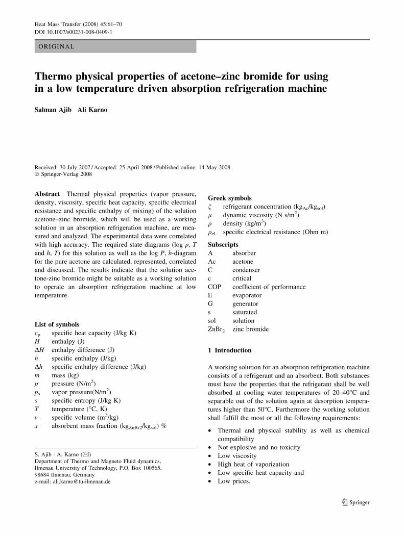
2.1 Density
The density was measured at various concentrations in
the range of temperatures from 0 to 36�C [11]. The
experimental results are plotted in Fig. 1 and correlated as
follows:
q ¼ 1:051385 � 0:002577258 � T þ 4:75227e� 6ð Þ � x3
ðg=cm3Þ ð1Þ
The used units for temperature T is (�C) and for 9 (kgzinc
bromide/kgsolution)%. The given correlation equation was
adapted in the temperature and concentration ranges of
0–36�C and from 30 to 50 mass% of zinc bromide,
respectively. The calculated values are plotted in Fig. 1. At
the comparison with the experimental results, it is clear,
that the equation 1 provides a very good result with about
2% deviation.
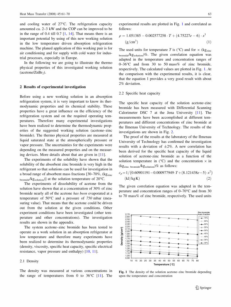
2.2 Specific heat capacity
The specific heat capacity of the solution acetone-zinc
bromide has been measured with Differential Scanning
Calorimeter DSC 7 at the Jena University [11]. The
measurements have been accomplished at different tem-
peratures and different concentrations of zinc bromide at
the Ilmenau University of Technology. The results of the
investigations are shown in Fig. 2.
The proof of the results at the laboratory of the Ilmenau
University of Technology has confirmed the investigation
results with a deviation of ±2%. A new correlation has
been derived for the specific heat capacity of the liquid
solution of acetone-zinc bromide as a function of the
solution temperature in (�C) and the concentration 9 in
(kgzinc bromide/kgsolution)% as follows:
cp¼1= 0:60901191�0:000977949�Tþ 8:121438e�5ð Þ�x2� �
kJ=kgKð Þ ð2Þ
The given correlation equation was adapted in the tem-
perature and concentration ranges of 0–70�C and from 30
to 70 mass% of zinc bromide, respectively. The used units
0,901,001,101,201,301,401,501,601,701,801,902,002,102,202,302,402,502,602,70
10 15 20 25 30 35 40 45 50 55 60 65 70 75 80
Temperature [°C]
Den
sity
[g
/cm
³]
70%
65%
60%
55%
50%
45%
40%
35%
30%
Zinc bromidemass fraction
Fig. 1 The density of the solution acetone–zinc bromide depending
upon the temperature and concentration
Heat Mass Transfer (2008) 45:61–70 63
123
for temperature T is (�C) and for 9 (kgzinc bromide/
kgsolution)%.
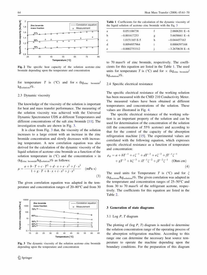
2.3 Dynamic viscosity
The knowledge of the viscosity of the solution is important
for heat and mass transfer performance. The measuring of
the solution viscosity was achieved with the Universal
Dynamic Spectrometer UDS at different Temperatures and
different concentrations of the salt zinc bromide [11]. The
investigation results are shown in Fig. 3.
It is clear from Fig. 3 that, the viscosity of the solution
increases to a large extent with an increase in the zinc
bromide concentration and slowly decreases with increas-
ing temperature. A new correlation equation was also
derived for the calculation of the dynamic viscosity of the
liquid solution of acetone–zinc bromide as a function of the
solution temperature in (�C) and the concentration 9 in
(kgzinc bromide/kgsolution)% as follows:
l ¼ aþ b � T þ c � T2 þ d � xþ e � x2 þ f � x3
1þ g � T þ h � xþ i � x2 þ j � x3mPa sð Þ
ð3Þ
The given correlation equation was adapted in the tem-
perature and concentration ranges of 20–80�C and from 30
to 70 mass% of zinc bromide, respectively. The coeffi-
cients for this equation are listed in the Table 1. The used
units for temperature T is (�C) and for 9 (kgzinc bromide/
kgsolution)%.
2.4 Specific electrical resistance
The specific electrical resistance of the working solution
has been measured with the CMD 210 Conductivity Meter.
The measured values have been obtained at different
temperatures and concentrations of the solution. These
values are illustrated in Fig. 4.
The specific electrical resistance of the working solu-
tion is an important property of the solution and can be
used for determination of the concentration of the solution
(till the concentration of 55% acetone) and according to
that for the control of the capacity of the absorption
refrigeration machine [15]. The experimental values are
correlated with the following equation, which expresses
specific electrical resistance as a function of temperature
and concentration:
qel ¼ aþ bT�1 þ cn�1 þ dT�2 þ en�2 þ fT�1n�1
þ gT�3 þ hn�3 þ iT�1n�2 þ jT�2n�1 Ohm cmð Þð4Þ
The used units for Temperature T is (�C) and for n(kgacetone/kgsolution)%. The given correlation was adapted in
the temperature and concentration ranges of 25–50�C and
from 30 to 70 mass% of the refrigerant acetone, respec-
tively. The coefficients for this equation are listed in the
Table 2.
3 Generation of state diagrams
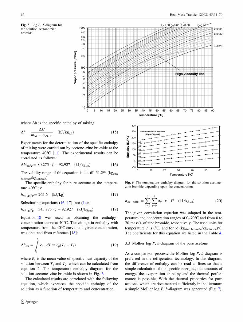
3.1 Log P, T diagram
The plotting of (log P, T) diagram is needed to determine
the solution concentration range of the operating process of
the absorption refrigeration machine. According to this
range one can determine the necessary heat source tem-
perature to operate the machine depending upon the
boundary conditions. For the preparation of this diagram
0,8
1
1,2
1,4
1,6
1,8
2
25 35 45 55 65 75 85
Temperature [°C]
Correlation equation
Measurement
Sp
ecif
ic h
eat
cap
acit
y [k
J/kg
.K]
Zinc bromidemass fraction
31%
70%
50%
Fig. 2 The specific heat capacity of the solution acetone–zinc
bromide depending upon the temperature and concentration
0,1
1
10
100
1000
10000
15 20 25 30 35 40 45 50 55 60 65
Temperature [°C]
Dyn
amic
vis
cosi
ty [
mP
a.s] Correlation equation
Measurement
Zinc bromidemass fraction
70%
60%
50%40%30%
Fig. 3 The dynamic viscosity of the solution acetone–zinc bromide
depending upon the temperature and concentration
Table 1 Coefficients for the calculation of the dynamic viscosity of
the liquid solution of acetone–zinc bromide with the Eq. 3
a 0.051106738 f 2.0606201 E-6
b -0.001617253 g 5.6658661 E-6
c 1.0151165 E-5 h -0.044457163
d 0.0094957964 i 0.0006597168
e -0.0002753312 j -3.2670638 E-6
64 Heat Mass Transfer (2008) 45:61–70
123

for the solution acetone–zinc bromide, the vapor pressure
must be measured for pure acetone as well as for the
solution acetone–zinc bromide.
Vapor pressures PS of many pure substances are known
from the literature and are described by correlation equa-
tions, e.g., the Antoine equations [16] as follows:
lnPs
Pc
� �¼ 1� yð Þ�1 ayþ by1;5 þ cy3 þ dy6
� �ð5Þ
With y ¼ 1� T
Tcð6Þ
The parameters of these equations for acetone can be
obtained from [17] as follows:
a = -7.45514, b = +1.202, c = -2.43926, d =
-3.3559
The vapor pressures for the solution acetone-zinc bro-
mide were measured at various concentrations (from a
minimal concentration of 30–66% in steps of 5%) in the
range of temperature (from 0 to 70�C). The maximum
deviation of measurements and calculations for the vapor
pressure amounts 15.85% at temperature of 58.1�C and
concentration of 30% (kgzinc bromide/kgsolution). The mini-
mum is 0.04% at temperature of 19.3�C and concentration
of 30% (kgzinc bromide/kgsolution). The experimental values
are correlated with the following equation, which expresses
vapor pressure as a function of temperature and concen-
tration [11]:
Psacetone�zinc bromide¼ exp
X2
i¼0
X2
j¼0
aij � Ti � xj barð Þ ð7Þ
The used units for temperature T is (�C) and for 9 (kgzinc
bromide/kgsolution)%. The coefficients for this equation are
listed in the Table 3.
The calculated results from Eqs. (5, 6 and 7) are plotted
in Fig. 5. Also the high viscosity line (crystallization line)
is clear in the diagram. Under this line the absorption
refrigeration machine cannot be operated. By using the
solution as work solution in the absorption refrigeration
machine one has to take in account this limitation.
3.2 Temperature–enthalpy diagram
The enthalpy change DH due to the mixing of components
‘‘a’’ and ‘‘b’’ to form solution ‘‘c’’, at the same pressure and
temperature, are given by [18]:
DH ¼ Hc � Ha þ Hbð Þ ð8Þ
If ‘‘a’’ represents the acetone (Ac), ‘‘b’’ the zinc bromide
(ZnBr2), and ‘‘c’’ the acetone-zinc bromide solution (sol),
Eq. 8 may be written:
DH ¼ Hsol � HAc þ HZnBr2ð Þ ð9Þ
The enthalpy H can be replaced with the specific enthalpy h
and the mass m as follows:
DH ¼ mAc þ mZnBr2ð Þ � hsol � mAc � hAc � mZnBr2
� hZnBr2
ð10Þ
The reference state for zero enthalpy was chosen as 40�C
for the absorbent zinc bromide. The Eq. 10 becomes:
DHj40�
C¼ mAc þ mZnBr2ð Þ � hsolj40
�C�mAc � hAcj40
�C ð11Þ
Rearranging:
hsolj40�
C¼mAc � hAcj40
�CþDHj40
�C
mAc þ mZnBr2
ð12Þ
Using the following relationship (concentration of the
refrigerant in the solution) into the Eq. 12,
n ¼ mAc
mAc þ mZnBr2
kgAc=kgsolð Þ ð13Þ
Then the Eq. 12 becomes:
hsolj40�
C¼ n � hAcj40�
CþDhj40�
C ð14Þ
0
200
400
600
800
1000
1200
1400
1600
1800
2000
30 35 40 45 50 55 60 65 70
Acetone mass fraction [%]
Sp
ecif
ic r
esis
tan
ce [
Oh
m.c
m]
25°C30°C35°C40°C45°C50°C
Fig. 4 The specific electrical resistance for the solution acetone–zinc
bromide depending upon the temperature and concentration
Table 2 Coefficients for the calculation of the specific electrical
resistance of the solution acetone–zinc bromide with the Eq. 4
a 1,605 f -384,661
b 26,741 g 2,454,940
c -158,568 h -1,234 E+8
d 237,886 i 1,936 E+8
e 6,183,595 j -33,760,052
Table 3 Coefficients for the calculation of the vapor pressure of the
solution acetone–zinc bromide with the Eq. 7
a00 -2.41 E+0 a10 5.35 E-2 a20 -2.13 E-4
a01 1.72 E-2 a11 -1.16 E-4 a21 3.66 E-6
a02 -5.58 E-4 a12 2.38 E-6 a22 -4.61 E-8
Heat Mass Transfer (2008) 45:61–70 65
123
where Dh is the specific enthalpy of mixing:
Dh ¼ DH
mAc þ mZnBr2
kJ=kgsolð Þ ð15Þ
Experiments for the determination of the specific enthalpy
of mixing were carried out by acetone–zinc bromide at the
temperature 40�C [11]. The experimental results can be
correlated as follows:
Dhj40�
C¼ 80:275 � n� 92:927 kJ=kgsolð Þ ð16Þ
The validity range of this equation is 4.4 till 31.2% (kgzinc
bromide/kgsolution).
The specific enthalpy for pure acetone at the tempera-
ture 40�C is:
hAcj40�
C¼ 265:6 kJ=kgð Þ ð17Þ
Substituting equations (16, 17) into (14):
hsolj40�
C¼ 345:875 � n� 92:927 kJ=kgsolð Þ ð18Þ
Equation 18 was used in obtaining the enthalpy–
concentration curve at 40�C. The change in enthalpy with
temperature from the 40�C curve, at a given concentration,
was obtained from reference [18]:
Dhsol ¼ZT2
T1
cp � dT ffi �cp T2 � T1ð Þ ð19Þ
where �cp is the mean value of specific heat capacity of the
solution between T1 and T2, which can be calculated from
equation 2. The temperature–enthalpy diagram for the
solution acetone–zinc bromide is shown in Fig. 6.
The calculated results are correlated with the following
equation, which expresses the specific enthalpy of the
solution as a function of temperature and concentration:
hAc�ZiBr2¼X1
i¼0
X4
j¼0
aij � xi � Tj kJ=kgsolð Þ ð20Þ
The given correlation equation was adapted in the tem-
perature and concentration ranges of 0–70�C and from 0 to
70 mass% of zinc bromide, respectively. The used units for
temperature T is (�C) and for 9 (kgzinc bromide/kgsolution)%.
The coefficients for this equation are listed in the Table 4.
3.3 Mollier log P, h-diagram of the pure acetone
As a comparison process, the Mollier log P, h-diagram is
preferred in the refrigeration technology. In this diagram,
the difference of enthalpy can be read as lines so that a
simple calculation of the specific energies, the amounts of
energy, the evaporation enthalpy and the thermal perfor-
mance is possible. With the thermal properties for pure
acetone, which are documented sufficiently in the literature
a simple Mollier log P, h-diagram was generated (Fig. 7).
10
100
1000
0 5 10 15 20 25 30 35 40 45 50 55 60 65 70 75 80 85 90
Temperature [°C]
Vap
or
pre
ssu
re [
mb
ar]
ξ=0,34ξ=0,50 ξ=0,40ξ=0,60ξ=1,00
800
200
300
400
500600
80
20
30
40
5060
ξ=0,30
ξ=0,20
High viscosity line
Fig. 5 Log P, T-diagram for
the solution acetone-zinc
bromide
-50
0
50
100
150
200
250
300
0 10 20 30 40 50
Temperature [°C]
En
thal
py
[KJ/
Kg
]
60
0,3
0,4
0,5
0,6
0,7
0,8
0,9
1
Concentration of acetone[Kg Ac/ Kg sol]
Fig. 6 The temperature–enthalpy diagram for the solution acetone–
zinc bromide depending upon the concentration
66 Heat Mass Transfer (2008) 45:61–70
123
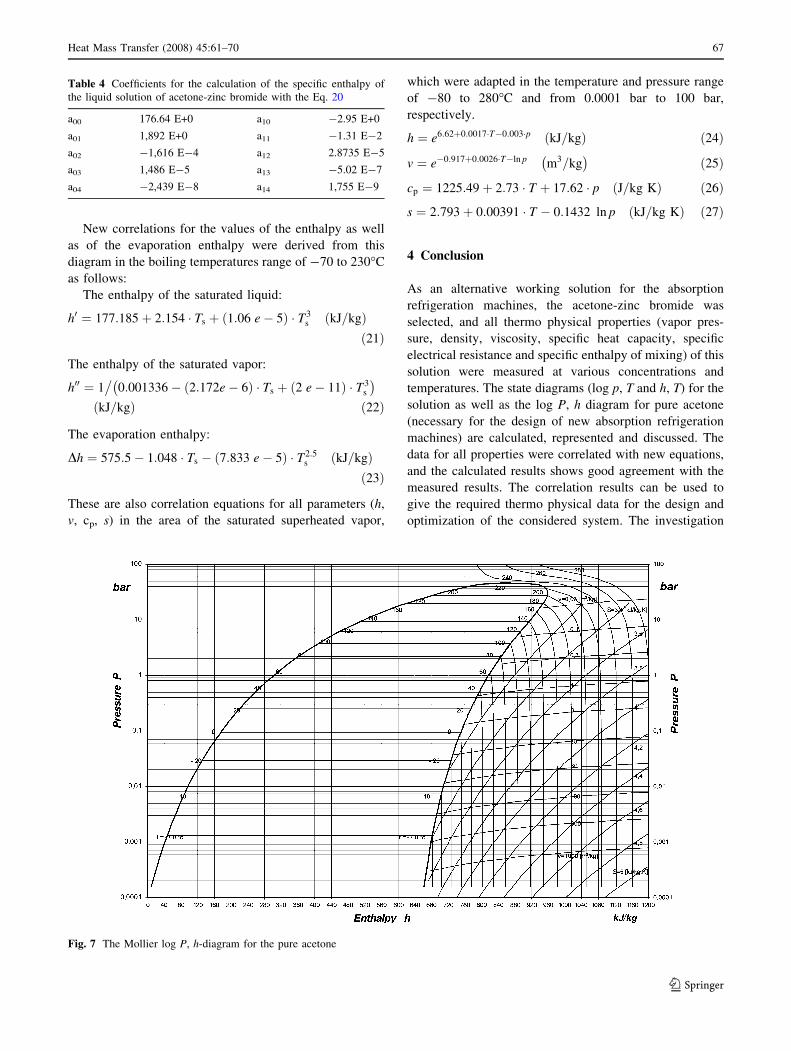
New correlations for the values of the enthalpy as well
as of the evaporation enthalpy were derived from this
diagram in the boiling temperatures range of -70 to 230�C
as follows:
The enthalpy of the saturated liquid:
h0 ¼ 177:185þ 2:154 � Ts þ 1:06 e� 5ð Þ � T3s kJ=kgð Þ
ð21Þ
The enthalpy of the saturated vapor:
h00 ¼ 1�
0:001336� 2:172e� 6ð Þ � Ts þ 2 e� 11ð Þ � T3s
� �
kJ=kgð Þ ð22Þ
The evaporation enthalpy:
Dh ¼ 575:5� 1:048 � Ts � 7:833 e� 5ð Þ � T2:5s kJ=kgð Þ
ð23Þ
These are also correlation equations for all parameters (h,
v, cp, s) in the area of the saturated superheated vapor,
which were adapted in the temperature and pressure range
of -80 to 280�C and from 0.0001 bar to 100 bar,
respectively.
h ¼ e6:62þ0:0017�T�0:003�p kJ=kgð Þ ð24Þ
v ¼ e�0:917þ0:0026�T�ln p m3=kg� �
ð25Þ
cp ¼ 1225:49þ 2:73 � T þ 17:62 � p J=kg Kð Þ ð26Þ
s ¼ 2:793þ 0:00391 � T � 0:1432 ln p kJ=kg Kð Þ ð27Þ
4 Conclusion
As an alternative working solution for the absorption
refrigeration machines, the acetone-zinc bromide was
selected, and all thermo physical properties (vapor pres-
sure, density, viscosity, specific heat capacity, specific
electrical resistance and specific enthalpy of mixing) of this
solution were measured at various concentrations and
temperatures. The state diagrams (log p, T and h, T) for the
solution as well as the log P, h diagram for pure acetone
(necessary for the design of new absorption refrigeration
machines) are calculated, represented and discussed. The
data for all properties were correlated with new equations,
and the calculated results shows good agreement with the
measured results. The correlation results can be used to
give the required thermo physical data for the design and
optimization of the considered system. The investigation
Table 4 Coefficients for the calculation of the specific enthalpy of
the liquid solution of acetone-zinc bromide with the Eq. 20
a00 176.64 E+0 a10 -2.95 E+0
a01 1,892 E+0 a11 -1.31 E-2
a02 -1,616 E-4 a12 2.8735 E-5
a03 1,486 E-5 a13 -5.02 E-7
a04 -2,439 E-8 a14 1,755 E-9
Fig. 7 The Mollier log P, h-diagram for the pure acetone
Heat Mass Transfer (2008) 45:61–70 67
123

results of an absorption refrigeration machine working with
this new working pair showed the possibility of using of it,
especially by drive the absorption refrigeration machine
with a low temperature heat sources (over 50�C). The
investigations on an absorption refrigeration machine with
refrigeration capacity of 10 kW have confirmed the pos-
sibility of using the working pair as working solution and
acetone as coolant. The advantages of using of this working
solution are based on the needed low drive temperature of
the heat source. The disadvantages are based on the bad
heat conductivity of acetone and on the low COP. Never-
theless we will continue the investigations on this new
working solution to improve its heat transfer properties
[19, 20].
Appendix
Calculated data of the thermo physical properties for the
solution acetone-zinc bromide (Tables 5, 6, 7, 8, 9 and 10).
Table 5 Specific heat capacity
(kJ/kg K)Temperature (�C) 25 30 35 40 45 50 55 60
Acetone %
30 1.018 1.023 1.028 1.033 1.038 1.044 1.049 1.055
35 1.078 1.084 1.089 1.095 1.101 1.107 1.113 1.119
40 1.140 1.147 1.153 1.160 1.166 1.173 1.180 1.187
45 1.204 1.212 1.219 1.226 1.234 1.241 1.249 1.256
50 1.270 1.278 1.286 1.294 1.302 1.310 1.319 1.327
55 1.335 1.344 1.353 1.362 1.371 1.380 1.389 1.399
60 1.400 1.409 1.419 1.429 1.439 1.449 1.459 1.470
65 1.462 1.472 1.483 1.494 1.505 1.516 1.527 1.539
70 1.521 1.532 1.544 1.555 1.567 1.579 1.592 1.604
Table 6 Vapor pressure (bar)Temperature (�C) 25 30 35 40 45 50 55 60
Acetone %
30 0.065 0.080 0.098 0.121 0.148 0.180 0.215 0.255
35 0.086 0.107 0.134 0.167 0.206 0.251 0.302 0.357
40 0.117 0.147 0.186 0.234 0.290 0.353 0.424 0.503
45 0.158 0.200 0.254 0.320 0.397 0.483 0.579 0.684
50 0.200 0.255 0.324 0.407 0.503 0.611 0.729 0.857
55 0.230 0.291 0.369 0.463 0.570 0.689 0.820 0.961
60 0.243 0.305 0.385 0.479 0.588 0.710 0.842 0.986
65 0.254 0.314 0.392 0.485 0.592 0.712 0.843 0.984
70 0.285 0.347 0.426 0.520 0.629 0.750 0.883 1.027
Table 7 Density (g/cm3)Temperature (�C) 25 30 35 40 45 50 55 60
Acetone %
30 2.617 2.604 2.591 2.578 2.565 2.553 2.540 2.527
35 2.292 2.279 2.266 2.253 2.241 2.228 2.215 2.202
40 2.013 2.001 1.988 1.975 1.962 1.949 1.936 1.923
45 1.778 1.765 1.752 1.739 1.726 1.713 1.700 1.687
50 1.581 1.568 1.555 1.542 1.529 1.517 1.504 1.491
55 1.420 1.407 1.394 1.381 1.368 1.356 1.343 1.330
60 1.291 1.278 1.265 1.252 1.240 1.227 1.214 1.201
65 1.191 1.178 1.165 1.152 1.139 1.126 1.113 1.101
70 1.115 1.102 1.089 1.077 1.064 1.051 1.038 1.025
68 Heat Mass Transfer (2008) 45:61–70
123
References
1. Ajib S, Gunther W, Karno A (2006) Optimisation potential of
solar thermal driven absorption refrigeration machine under using
of a new work solution. World Renewable Energy, 19–25 August,
Florence, Italy (A5-ST89)
2. Sierra FZ, Best R, Holland FA (1993) Experiments on an
absorption refrigeration system powered by a solar pond. Heat
Recovery Syst CHP 13(5S):401–408
3. Ajib S, Schultheis P (1998) Untersuchungsergebnisse einer
solarthermisch betriebenen Absorptionskalteanlage. TAB Tech-
nik am Bau, Nr.2, S:49–54, ISSN 0341–2032
4. Kunze G (2000) Efficient solar cooling with an improved
ammonia—absorption system. Renewable energy World, 3.
Jahrgang, Nr.6, S:111–112, ISSN 1462–6381
5. Meißner E (2004) Projekterfahrungen mit solaren Kaltemaschi-
nen: 17 kW NH3-H2O Absorptionskalteanlage fur Weinkuhlung
beim Weingut Peitler in der Steiermark/Osterreich. Band Drittes
Symposium Solares Kuhlen in der Praxis, HfT Stuttgart 26-27
April, S:59–80
6. Jakob U, Schneider D, Eicker U (2004) Entwicklung einer Dif-
fusions- Absorptionskaltemaschine kleiner Leistung (2,5 kW).
Band Drittes Symposium Solares Kuhlen in der Praxis, HfT
Stuttgart 26-27 April, S:125–144
7. Schweigler CH, Costa A, Hogenauer-Lego M, Harm M, Ziegler F
(2002) Entwicklung und Betrieb einer 10 kW H2O/LiBr-
Absorptionskaltemaschine. Band Zweites Symposium Solares
Kuhlen in der Praxis, HfT Stuttgart, 10-11 juni, S:110–134
8. Safarik M, Weidner G (2004) Neue 15 kW H2O-LiBr Absorp-
tionskalteanlage im Feldtest fur thermische Anwendungen. Band
Drittes Symposium Solares Kuhlen in der Praxis, HfT Stuttgart
26-27 April, S:159–172
9. Kuhn A, Albers J, Harm M, Kohlenbach P, Petersen S, Schwei-
gler CH, Ziegler F (2004) Betriebsverhalten einer 10 kW
Absorptionskalteanlage fur niedrige Antriebstemperaturen. DKV-
Tagungsbericht, Bremen 17-19 November, Band II.1, S:169–
182
10. Ajib S, Al-Najjar S, Wegner R (2000) Ein Arbeitsstoffgemisch
fur Niedertemperaturbetriebene Absorptionskalteanlage. Offen-
legungsschrift DE A1 101 41657, TU Ilmenau, Juli
11. Al-Najjar S (2002) Untersuchung geeigneter Arbeitsstoffpaare fur
Absorptionskaltemaschinen unter Berucksichtigung der Warme-
prozessoptimierung. PhD thesis, TU Ilmenau, Januar
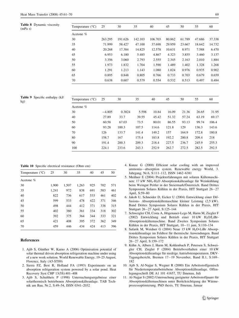
Table 8 Dynamic viscosity
(mPa s)Temperature (�C) 25 30 35 40 45 50 55 60
Acetone %
30 263.295 191.626 142.103 106.703 80.862 61.789 47.686 37.338
35 71.999 58.427 47.100 37.698 29.959 23.667 18.642 14.732
40 20.268 17.384 14.825 12.578 10.631 8.971 7.588 6.470
45 6.953 6.180 5.485 4.867 4.323 3.855 3.460 3.137
50 3.356 3.060 2.793 2.555 2.345 2.163 2.010 1.884
55 1.973 1.832 1.704 1.590 1.489 1.402 1.328 1.268
60 1.291 1.213 1.143 1.080 1.024 0.976 0.935 0.902
65 0.895 0.848 0.805 0.766 0.733 0.703 0.679 0.659
70 0.638 0.607 0.579 0.554 0.532 0.513 0.497 0.484
Table 9 Specific enthalpy (kJ/
kg)Temperature (�C) 25 30 35 40 45 50 55 60
Acetone %
30 -4.805 0.3824 5.598 10.84 16.09 21.36 26.65 31.95
40 27.89 33.7 39.55 45.42 51.32 57.24 63.19 69.17
50 60.58 67.03 73.5 80.01 86.55 93.13 99.74 106.4
60 93.28 100.3 107.5 114.6 121.8 129 136.3 143.6
70 126 133.7 141.4 149.2 157 164.9 172.8 180.8
80 158.7 167 175.4 183.8 192.2 200.8 209.4 218
90 191.4 200.3 209.3 218.4 227.5 236.7 245.9 255.3
100 224.1 233.6 243.3 252.9 262.7 272.5 282.5 292.5
Table 10 Specific electrical resistance (Ohm cm)
Temperature (�C) 25 30 35 40 45 50
Acetone %
30 1,900 1,507 1,263 925 702 571
35 1,241 972 838 691 583 461
40 822 736 617 533 461 402
45 599 533 478 422 371 346
50 498 444 412 371 338 315
55 402 380 361 334 318 302
60 392 375 364 344 333 321
65 421 408 395 372 362 349
70 459 446 434 424 413 396
Heat Mass Transfer (2008) 45:61–70 69
123

12. Pitatowsky I, Rivera W, Romero RJ (2001) Thermodynamic
analysis of monomethylamine-water solutions in a single-stage
solar absorption refrigeration cycle at low generator tempera-
tures. In Solar Energy Mater Solar Cells 70(S):287–300
13. De Lucas A, Donate C, Villasenor J, Rodriguez JF (2004) Per-
formance evaluation and simulation of a new absorbent for an
absorption refrigeration system. Int J Refrigeration 27(S):324–
330
14. Karno A (2006) Simulation und Optimierung der Betriebsweise
einer solarthermisch betriebenen Absorptionskaltemaschine unter
Berucksichtigung verschiedener Arbeitsstoffpaare. PhD thesis,
TU Ilmenau
15. Ajib S (2005) Vorrichtungen und Verfahren zur Bestimmung der
Losungskonzentration in einer Absorptionskaltemaschine und
Verfahren zur Regulierung der Leistung einer Absorptionskalt-
emaschine. patent notification 102005033990.5, Tu Ilmenau, July
16. Lucas K, Luckas M (1993) Berechnungsmethoden fur Stoffei-
genschaften. In VDI- Warmeatlas. VDI- Verlag, Dusseldorf, S: Da
17. Reid RC, Prausnitz JM, Poling BE (1987) The properties of gases
and liquids. McGraw Hill, New York
18. Sargent SL, Beckman WA (1968) Theoretical performance of an
ammonia-sodium thiocyanate intermittent absorption refrigera-
tion cycle. Solar Energy 12(S):137–146
19. Ajib S, Karno A, Nilius A, Aust J, Thess A (2006) Optimierung der
Betriebsweise einer Absorptionskalteanlage zur Kuhlung und
Raumklimatisierung unter Anwendung von neuen Arbeitsstoffpaa-
ren und Niedertemperaturantriebsquellen. Abschlussbericht des
Projekts 0327320A, TU Ilmenau
20. Ajib S, Gunther W (2007) Investigation results of an absorption
refrigeration machine operated solar thermally for cooling and air
conditioning under using of a new working solution. In: 2nd
international conference solar air-conditioning, 18–19 Oct.,
Tarragona, Spain
70 Heat Mass Transfer (2008) 45:61–70
123
Related Documents