Thermo-Mechanical Buckling Failure of Thermal Barrier Coatings with Arbitrary Delamination Location W. G. Mao 1,2 , C. Y. Dai 1,2 ,Y. C. Zhou 1,2,∗ and X. H. Yu 1,2 1 Faculty of Materials & Optoelectronics Physics, Xiangtan University, Hunan 411 105, China 2 Key Laboratory for Advanced Materials and Rheological Properties of Ministry of Education, Xiangtan University, Xiangtan, Hunan 411 105, China ∗ [email protected] Abstract A one-dimensional interface delamination model is introduced to analyze the thermo-mechanical buck- ling characteristic of Thermal Barrier Coatings (TBCs) system with arbitrary across-the-width delami- nation. Equilibrium equations, stability equations and characteristic equation governing buckling under external thermal and mechanical loadings are derived on the basis of the first order shear deformation theory and the State Space Method (SSM). Different types of thermal loading and temperature gradi- ent across the thickness are considered, and the thermo-mechanical buckling loadings are accurately obtained. Finally the effects of Thermal Barrier Coatings (TBCs) system aspect ratio, relative thickness, delamination location and temperature gradient on thermo-mechanical buckling failure of TBCs are all discussed. Keywords: Thermal Barrier Coatings, Thermo-Mechanical Buckling Failure, Delamination 1 Introduction Thermal Barrier Coatings (TBCs) are commonly used as protective coatings for advanced power engi- neering applications to improve performance and thermal efficiency [1–4] . It consists of a ceramic coating, a Thermally Grown Oxide (TGO) that thickens as the system cycles, bond coat that provides the oxida- tion resistance, and substrate. The function of TBC is that lowering the temperature of substrate prolongs the life of the devices. However, in its service, oxidation phenomenon occurs between the ceramic coat- ing and bond coat in an aggressive environment. The oxidation film (mainly Al 2 O 3 ) forms and thickens with respect to thermal cycling, which will result in 1 interface delamination, crack nucleation, propaga- tion and coalescence. On the other hand, due to materials mismatch and temperature gradient in TBCs, the stress in the ceramic coating is compressive on cooling to the ambient temperature. Furthermore, the residual stress accumulates with thermal cycling [5–7] . Eventually, it will result in the spalling or buck- ling failure of the ceramic coating. Gell et al. had studied that the spallation life of TBCs on a MCrAlY bond coated Ni-base superalloy substrate deposited under the optimized processing conditions. They found that the buckling spallation is the failure of TBCs occurring within the ceramic top coat under thermal cyclic test, as shown in Fig. 1 [8] . Hutchinson et al. had analyzed that the influence of prototyp- ical imperfections on the nucleation and propagation stages of delaminations of compressed thin films. Energy release rates for separations that develop from imperfections had been calculated. They found ∗ Corresponding author ADVANCES IN VIBRATION ENGINEERING, 6(2) 2007 © KRISHTEL eMAGING SOLUTIONS PRIVATE LIMITED

Welcome message from author
This document is posted to help you gain knowledge. Please leave a comment to let me know what you think about it! Share it to your friends and learn new things together.
Transcript

Thermo-Mechanical Buckling Failure of Thermal BarrierCoatings with Arbitrary Delamination Location
W. G. Mao1,2, C. Y. Dai1,2,Y. C. Zhou1,2,∗ and X. H. Yu1,2
1Faculty of Materials & Optoelectronics Physics, Xiangtan University, Hunan 411 105, China2Key Laboratory for Advanced Materials and Rheological Properties of Ministry of Education, Xiangtan
University, Xiangtan, Hunan 411 105, China∗[email protected]
Abstract
A one-dimensional interface delamination model is introduced to analyze the thermo-mechanical buck-ling characteristic of Thermal Barrier Coatings (TBCs) system with arbitrary across-the-width delami-nation. Equilibrium equations, stability equations and characteristic equation governing buckling underexternal thermal and mechanical loadings are derived on the basis of the first order shear deformationtheory and the State Space Method (SSM). Different types of thermal loading and temperature gradi-ent across the thickness are considered, and the thermo-mechanical buckling loadings are accuratelyobtained. Finally the effects of Thermal Barrier Coatings (TBCs) system aspect ratio, relative thickness,delamination location and temperature gradient on thermo-mechanical buckling failure of TBCs are alldiscussed.
Keywords: Thermal Barrier Coatings, Thermo-Mechanical Buckling Failure, Delamination
1 Introduction
Thermal Barrier Coatings (TBCs) are commonly used as protective coatings for advanced power engi-neering applications to improve performance and thermal efficiency[1–4]. It consists of a ceramic coating,a Thermally Grown Oxide (TGO) that thickens as the system cycles, bond coat that provides the oxida-tion resistance, and substrate. The function of TBC is that lowering the temperature of substrate prolongsthe life of the devices. However, in its service, oxidation phenomenon occurs between the ceramic coat-ing and bond coat in an aggressive environment. The oxidation film (mainly Al2O3) forms and thickenswith respect to thermal cycling, which will result in 1 interface delamination, crack nucleation, propaga-tion and coalescence. On the other hand, due to materials mismatch and temperature gradient in TBCs,the stress in the ceramic coating is compressive on cooling to the ambient temperature. Furthermore, theresidual stress accumulates with thermal cycling[5–7]. Eventually, it will result in the spalling or buck-ling failure of the ceramic coating. Gell et al. had studied that the spallation life of TBCs on a MCrAlYbond coated Ni-base superalloy substrate deposited under the optimized processing conditions. Theyfound that the buckling spallation is the failure of TBCs occurring within the ceramic top coat underthermal cyclic test, as shown in Fig. 1[8]. Hutchinson et al. had analyzed that the influence of prototyp-ical imperfections on the nucleation and propagation stages of delaminations of compressed thin films.Energy release rates for separations that develop from imperfections had been calculated. They found
∗Corresponding author
ADVANCES IN VIBRATION ENGINEERING, 6(2) 2007 © KRISHTEL eMAGING SOLUTIONS PRIVATE LIMITED

150 W. G. MAO et al. / ADVANCES IN VIBRATION ENGINEERING, 6(2) 2007
Fig. 1. Cross-sectional SEM figure of the bucklingspallation failure of TBCs under thermalcyclic tests[8].
that a critical thin thickness for nucleation and acritical imperfection[9]. Moreover, Chai et al. hadanalyzed delamination buckling and growth in com-posites[10–12]. In these works different approacheswere used, leading in some cases to different results.Kardomateas and Comiez had obtained the exper-imental results on delamination buckling[13, 14].Yin investigated that a thermo-mechanical bucklinganalysis of multilayered laminates with (across-the-width) strip delaminations, which was conductedon the basis of anisotropic thermoelasticity of theconstituent layers and the Kirchhoff Love hypoth-esis of the classical laminate theory. An exact buckling analysis was presented for a multilayered stripdelamination model[15]. Based on the classical nonlinear von Karman plate theory, Ma and Wang studiedthat the axisymmetric large deflection bending of a functionally graded circular plate under the conditionof thermal-mechanical loadings. The axisymmetric thermal post-buckling behavior of a functionallygraded circular plate was also investigated[16].
However, there does not exist, to the author’ knowledge, for the investigation thermo-mechanicalbuckling failure of Thermal Barrier Coatings (TBCs) system with arbitrary (across-the-width) delam-ination by using the first order shear deformation theory and the State Space Method (SSM). In thispaper, the emphasis will be on the thermo-mechanical buckling delamination in TBCs under differenthigh temperature gradients and applied compressive loadings. With the assumption of generalized planedeformation, equilibrium equations, stability equations and characteristic equation governing bucklingunder external thermal and mechanical loadings are to be derived on the basis of the first order sheardeformation theory and the State Space Method (SSM).
2 Model
2.1 Problem definition
Fig. 2. Schematic of the analysis model of multilayeredTBCs system with an arbitrary across-the-widthdelamination in the present study
In the present study, the configuration of thedelaminated multilayered TBCs system is repre-sented in Fig. 2. It will be regarded as a delami-nated beam-plate system, which is assumed to bea homogeneous, isotropic system. The thicknessand length are, respectively, H and L. An arbi-trary delamination with length a at depth h3 fromthe top surface of the beam-plate exists. The mul-tilayered TBCs system is divided into four regionsdue to the presence of interface delamination. Theleft tip of the delamination is located at length l1from the left edge of the multilayered TBCs sys-tem. A mechanical force P is applied at the twoedges of TBCs system and the load is used to approximately replace the compressive residual stress in
THERMO- MECHANICAL BUCKLING FAILURE 151
the ceramic coating accumulated in its service. So the multilayered TBCs system is compressed by theaxial loadP at the two edges and heated from the initial state to different high temperatures. An interfacedelamination exists between the regions 2 and 3, which means the weakest adhesion region. However,the interfaces in the regions 1 and 4 represent the strong adhesion region, which can be regarded thatthe delamination/crack will not propagate along these interfaces in this paper. The delaminated TBCssystem is assumed to be clamped at the two edges. For simplicity, the following assumptions are made.The compressive load is uniform and uniaxial. The delamination with length a and the lager temper-ature gradient through thickness exist prior to applying the compressive load. ‘Slender’ beam-plate isassumed to be easy to buckle first between the regions 2 and 3. Regions 2 and 3 are assumed to be not incontact with each other in the initial stage of buckling because region 2 is more slender and flexible thanregion 3. The necessary conditions and equations required to derive the governing buckling equationare discussed in the following sections.
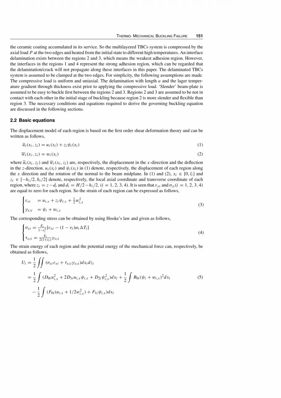
2.2 Basic equations
The displacement model of each region is based on the first order shear deformation theory and can bewritten as follows,
ui(xi, zi) = ui(xi)+ ziψi(xi) (1)
wi(xi, zi) = wi(xi) (2)
where ui(xi, zi) and wi(xi, zi) are, respectively, the displacement in the x-direction and the deflectionin the z-direction. ui(xi) and ψi(xi) in (1) denote, respectively, the displacement of each region alongthe x direction and the rotation of the normal to the beam midplane. In (1) and (2), xi ∈ [0, li] andzi ∈ [−hi/2, hi/2] denote, respectively, the local axial coordinate and transverse coordinate of eachregion, where zi = z−di and di = H/2−hi/2, (i = 1, 2, 3, 4). It is seen that εyi and σzi(i = 1, 2, 3, 4)are equal to zero for each region. So the strain of each region can be expressed as follows,
εxi = ui,x + ziψi,x + 1
2w2i,x
γxzi = ψi + wi,x
(3)
The corresponding stress can be obtained by using Hooke’s law and given as follows,σxi = Ei
1−v2i
[εxi − (1 − vi)αi�Ti]
τxzi = Ei2(1+vi ) γxzi
(4)
The strain energy of each region and the potential energy of the mechanical force can, respectively, beobtained as follows,
Ui = 1
2
∫∫(σxiεxi + τxziγxzi)dxidzi
= 1
2
∫(D0iu
2i,x + 2D1iui,xψi,x +D2iψ
2i,x)dxi + 1
2
∫B0i (ψi + wi,x)
2dxi (5)
− 1
2
∫(F0i (ui,x + 1/2w2
i,x)+ F1iψi,x)dxi

152 W. G. MAO et al. / ADVANCES IN VIBRATION ENGINEERING, 6(2) 2007
Vi = −Pi∫εxidxi = −Pi
∫(ui,x + ziψi,x + 1
2w2i,x)dxi (6)
where the stiffness coefficients in (5) are listed as follows,
{D0iD1iD2i} =n∑i=1
∫ hihiQ11i{1 zi z2
i }dzi
{B0i} =n∑i=1
∫ hihi−1
Q55i{1}dzi
{F0i F1i} =n∑i=1
∫ hihi−1
Ri�Ti(zi){1 zi}dzi
(7)
where Q11i and Q55i in (7) are proportionality invariants and equal to, respectively, Ei/(1 − v2i ) and
Ei/2(1 + vi). Ri and�Ti are equal to, respectively,Eiαi/(1 − vi) and Ti(z)−T0(z). It should be notedthat Pi denotes the axial load of the ith region. In order to simplify the analysis, in (6), P1 = P2 = P
and the local axial force Pi is approximatively regarded as hiP/H . Therefore, the total potential energyof the multilayered TBCs system can be written as,
∏=
4∑i=1
∏i
(8)
where∏
i= Ui + Vi.
To study the buckling character of the multilayered TBCs system by the potential energy method, theunknown displacements must be identified firstly. According to the principle of virtual displacement,the displacement variables of the ith region are divided into two parts,
ui = u0
i + uai
ψi = ψ0i + ψai
wi = w0i + wai
(9)
where {u0i ψ
0i w
0i } are the displacement functions of initiate balance state and {uai ψai wai } arey?
small variables of the displacement function, when the buckling phenomenon of TBC systemoccurs. The balance equations of the ith region can be deduced by using the potential variationprinciple,
D0iu
ai,xx +D1iψ
ai,xx = 0
D1iuai,xx +D2iψ
ai,xx − B0i (ψ
ai + wai,x) = 0 (i = 1, 2, 3, 4)
Piwai,xx − B0i (ψ
ai,x + wai,xx)+ 1
2F0iwai,xx = 0
(10)

THERMO- MECHANICAL BUCKLING FAILURE 153
2.3 Boundary conditions
For clamped boundary conditions, the following results can be obtained,
x1 = 0 ua1 = ψa1 = wa1 = 0 (11)
x4 = l4 ua4 = ψa4 = wa4 = 0 (12)
So the continuity of displacement at the two positions A and B, as shown in Fig. 2, must be satisfiedand can be written as
uai (0) = ua1(l1)+ diψ
a1 (l1)
ψai (0) = ψa1 (l1)
wai (0) = wa1 (l1)
(13)
uai (li) = ua4(0)+ diψ
a4 (0)
ψai (li) = ψa4 (0)
wai (li) = wa4 (0)
(14)
where i = 2, 3. In order to simplify the analysis, the generalized forces are defined as follows,
Xi = D0iuai,x +D1iψ
ai,x − F0i/2 (15)
φi = D1iuai,x +D2iψ
ai,x − F1i/2 (16)
Zi = B0i (ψai + wai,x)− Piw
ai,x − F0iw
ai,x/2 (17)
Furthermore, the balance of generalized forces at both tips A and B can be written as,
Xj(l14) =∑i=2,3
Xi(l23) (18)
φj (l14) =∑i=2,3
[diXi(l23)+ φi(l23)] (19)
Zj (l14) =∑i=2,3
Zi(l23) (20)
where
[j l14 l23] =
[1 l1 0] x = l1
[4 0 l2] x = l2
(21)
2.4 State-space method
In the following discussion, the State Space Method (SSM) is introduced to describe the buckling failurebehavior of the multilayered TBCs system with an across-the-width interface delamination. Therefore,

154 W. G. MAO et al. / ADVANCES IN VIBRATION ENGINEERING, 6(2) 2007
all variables of each region can be expressed as a form of state space method,
{ηi} = {uai ψai wai uai,x ψ
ai,x w
ai,x}T (22)
where “T ” denotes the transposition of matrix in (22). Therefore, the governing balance equation of theith region can be written as,
dηi/dxi = Siηi (23)
where the coefficients matrix Si is defined as,
Si =[
03×3 I3×3
C−11i C2i C
−11i C3i
](24)
where I3×3 and 03×3 in (24) are 3-order unit matrixes and zero matrix, respectively. The forms ofcoefficient matrixes Cij are also given in the appendix A. The solution of the governing balance (23)can be obtained as follows,
ηi = eSixi η0i = Ki(xi)η
0i (25)
where η0i is an integral invariant matrix, i.e., η0
i = (Ci1Ci2 · · ·Ci6)T . Ki(xi) is equal to eSixi and denotes
the coefficient of η0i in (25). Finally, all the boundary conditions and continuity conditions are rewritten
as the state-space form,
A2K1(0)η01 = 0 (26)
A2K4(l4)η04 = 0 (27)
A21K1(l1)η
01 − A2K2(0)η
02 = 0 (28)
A31K1(l1)η
01 − A2K2(0)η
03 = 0 (29)
A21K4(0)η
04 − A2K2(l2)η
02 = 0 (30)
A31K4(0)η
04 − A2K3(l3)η
03 = 0 (31)
A13K1(l1)η
01 − A2
4K2(0)η02 − A3
4K3(0)η03 = 0 (32)
A43K4(0)η
04 − A2
4K2(l2)η02 − A3
4K3(l3)η03 = 0 (33)
In the above equations, the coefficients are given in the appendix A. The total integral invariant matrixof the multilayered beam-plate is defined as,
η0 = {(η01)T (η0
2)T (η0
3)T (η0
4)T }T (34)
where “T ” represents the transposition of matrix. Therefore, the equations (26 to 33) can be written asa linear algebraic equations,
Mη0 = 0 (35)

THERMO- MECHANICAL BUCKLING FAILURE 155
where,
M =
A2K1(0) 0 0 0
0 0 0 A2K4(l4)
A21K1(l1) −A2K2(0) 0 0
A31K1(l1) 0 −A2K3(0) 0
0 −A2K2(l2) 0 A21K4(0)
0 0 −A2K3(l3) A31K4(0)
A13K1(l1) −A2
4K2(0) −A34K3(0) 0
0 −A24K2(l2) −A3
4K3(l3) A43K4(0)
(36)
The system has a nonzero solution if and only if the determinant of the coefficient matrix is equal tozero. So the characteristic equation is given by
|M| = 0 (37)
The lowest eigen value of the determinant of (37) represents the critical thermo-mechanical bucklingload.
2.5 Temperature field across thickness
For a thermal barrier ceramic coatings system, the temperature change is not uniform in its service. Thetemperature rises usually much higher at the ceramic side than on the metal side of the system. In orderto simplify the analysis, it is assumed that the temperature gradient fields vary linearly in the thicknessdirection, z. For this case, the temperature distribution across the thickness is governed by the followingequation and given as follows,
T (z) =
Ts−Tbhc+ht+hb × z+ Tb (hb + ht ≤ z ≤ hb + ht + hc)
Tb (−hs ≤ z ≤ 0)(38)
As shown in Fig. 2, where Ts and Tb denote, respectively, the temperature on the top and bottom surfaceof the delaminated TBCs system. The parameters hc, ht , hb and hs denote, respectively, the thicknessof the ceramic coating, Thermally Grown Oxide (TGO), bond coat and substrate.
3 Results and Discussion
In the paper, all thermal-mechanical properties in TBCs, such as thermal conductivity, thermal expansioncoefficient α(T ), Young’s modulus E(T ) and Poisson’s ratio ν(T ), are temperature dependent. Theproperties used in the calculations are taken from the Ref.[5] and listed in the AppendixB. The thicknessof each layer, hc, ht , hb and hs , are equal to, respectively, 0.35 mm, 10µm, 0.1 mm and 2.0 mm. Thetotal length L is equal to 40 mm. In practical situation, the surface temperature of the ceramic coating(Ts) is allowed to vary in the range of 800◦C to 1500◦C. But the temperature on the bottom of TBCssystem (Tb) remains close to 800◦C. Moreover, let λ be the temperature gradient, i.e., λ = Ts − Tb.

156 W. G. MAO et al. / ADVANCES IN VIBRATION ENGINEERING, 6(2) 2007
Fig. 3 Relationship of non-dimensional critical buckling loading with respect to temperature gradient underconditions of different interface delamination lengths.
3.1 Effects of temperature gradient and compressive loading
Generally, the critical thermo-mechanical buckling loading of TBCs is mainly influenced by many fac-tors, such as interface crack length (a), temperature gradient across thickness (λ), the total thickness(H), the total length (L) and the ceramic coating thickness (hc). The calculated results indicate thatthe interface delamination length and temperature gradient are the key parameters to control the criticalthermo-mechanical buckling loading. Fig. 3 shows the relationship of non-dimensional critical bucklingloading (Pcr/Pu) with respect to temperature gradient (λ) under the different interface delaminationlength, where Pu denotes the corresponding critical thermo-mechanical buckling loading of the intactmultilayered TBCs system. It is clear that the Pcr/Pu decreases with the increase of the temperature gra-dient (λ) and delamination length. When the interface delamination length is small and the temperaturegradient (λ) across thickness is low, for example, a = 0.5 mm and λ ≤ 200◦C, the critical thermo-mechanical buckling loading is almost equal to that of the intact TBCs system. When a = 0.5 mm andλ ≥ 400◦C, the Pcr/Pu decreases rapidly. Furthermore, the value of Pcr/Pu is independent on temper-ature gradient (λ) and becomes very small when the interface delamination length arrives at 4.0 mm.So the interface delamination length has an important influence on the non-dimensional buckling load-ing. On the other hand, the relationship of the critical thermal buckling temperature (Tcr ) with respectto the different applied compressive loadings (P ) is shown in Fig. 4 under different interface delam-ination lengths. It can be seen that thermal buckling temperature decreases gradually with respect tothe increase of the compressive loading at the two edges of TBC system when the interface delamina-tion length is small. As the delamination length increases, the compressive loading has strong influenceon the value of thermal buckling temperature. For example, when a = 3 mm and P = 5 × 10⁵ N/m,the Tcr approximately equals 1765◦C. However, when a = 3 mm and P = 5 × 10⁷ N/m, the Tcris very small and approximately equals 1408◦C. Note that the value of applied compressive loading(P ) in Fig. 4 should be smaller than that of the critical buckling loading at ambient. Otherwise, itwill result in buckling failure of TBC system at ambient before the TBCs system is heated up to hightemperature.

THERMO- MECHANICAL BUCKLING FAILURE 157
Fig. 4 Effect of applied compressive loading and interface delamination length on thermal buckling temperature.
3.2 Effect of non-dimensional interface crack length
Fig. 5. Non-dimensional critical buckling loading plottedas a function of non-dimensional interface cracklength with respect to conditions of differenttemperature gradient
Firstly, let γ be the non-dimensional inter-face delamination length and equal a/L. Fig. 5shows the relationship of the non-dimensionalcritical buckling loading (Pcr/Pu) with respectto the non-dimensional interface delaminationlength (γ ) under different temperature gradi-ents (λ) across the thickness. When the γ issmall, for example, γ ≤ 0.02, the correspond-ing Pcr/Pu is strongly dependent on tempera-ture gradient (λ). It decreases rapidly as the non-dimensional interface delamination length (γ )increases. On the other hand, for a same γ , thevalue of Pcr/Pu also decreases with respect tothe increase of temperature gradient. However,when the γ becomes larger, for instance, γ ≥0.08, the temperature gradient (λ) has a littleinfluence on the Pcr/Pu. Fig. 6 shows the rela-tionship of thermal buckling temperature andnon-dimensional interface delamination length(γ ) under different compressive loadings. It isclear that the thermal buckling temperature (Tcr ) decreases gradually with respect to delamination lengthincrease. It is found that the compressive loading at the two edges of the TBCs system has a little influ-ence on thermal buckling when the applied compressive loading is small.

158 W. G. MAO et al. / ADVANCES IN VIBRATION ENGINEERING, 6(2) 2007
Fig. 6 Relationship of critical thermal buckling temperature and non-dimensional length under the conditions ofdifferent applied compressive loadings
3.3 Effect of interface delamination location
In order to describe the influence of asymmetric behavior of interface delamination, let Xcenter be thedistance from the left edge of the multilayered TBCs system to the left tip of the delamination. Therelationship of the thermo-mechanical buckling loading with respect to non-dimensional Xcenter/L isshown in Fig. 7, where the interface delamination length is 0.2 mm. It can be seen that the critical thermo-mechanical buckling loading is proportional to the non-dimensionalXcenter/L. It means that the criticalthermo-mechanical buckling loading (Pcr ) can achieve the largest value when the interface delaminationlocates the symmetric location of TBCs system. Moreover, it is clearly seen that temperature gradienthas a little influence on the critical thermo-mechanical buckling loading when the interface delaminationlength is too small.
However, when the interface delamination length achieves 1.0 mm, the effect of the non-dimensionalXcenter/L on the thermo-mechanical buckling loading varies with the increase of temperature gradient,as shown in Fig. 8. If temperature gradient across the thickness is not high, e.g., λ ≤ 400◦C, the criticalthermo-mechanical buckling loading firstly increases withXcenter/L and then remains invariant. On theother hand, when the temperature gradient is heated to 700◦C, the buckling loading (Pcr ) is independenton the Xcenter/L and keeps invariant. Especially, when the interface delamination length approaches2.0 mm, this relationship is more visible, as shown in Fig. 9. For the same temperature gradient, the criticalthermo-mechanical buckling loadings approximately keep invariant in spite of the non-dimensionalXcenter/L change. It is seen that the critical thermo-mechanical buckling loading decreases quickly withlarger temperature gradients. For example, when the temperature gradient (λ) across the thickness isequal to zero, the corresponding critical buckling loading (Pcr ) equals 3.3 GN/m. When the λ approaches700◦C, the Pcr equals 1.0 GN/m. The former critical buckling loading is approximately three timesas large as the latter. So the calculated results indicate that the effects of the asymmetry behavior ofinterface delamination on the critical buckling failure of TBCs system will gradually decrease andvanish completely as the interface delamination length and temperature gradient increase. On the other

THERMO- MECHANICAL BUCKLING FAILURE 159
hand, the relationship of the non-dimensional critical buckling loading (Pcr/Pu) with respect to thenon-dimensional Xcenter/L is shown in Fig. 10, where the interface delamination length is 2.0 mm. It isfound that the non-dimensional critical buckling loading (Pcr/Pu) decreases gradually when the non-dimensional Xcenter/L and temperature gradient increase.
Fig. 7 Variation of the thermo-mechanical bucklingloading with respect to non-dimensional, rel-ative to different temperature gradient, whereinterface delamination length equals
Fig. 8 Variation of the thermo-mechanical bucklingloading with respect to non-dimensional, rela-tive to different temperature gradients, whereinterface delamination length equals
Fig. 9 Variation of thermo-mechanical buckling load-ing with respect to the non-dimensional, relativeto the different temperature gradients, where theinterface delamination length equals. Effect ofasymmetric behavior of interface delaminationvanishes completely
Fig. 10 Relationship of the non-dimensional criticalbuckling loading, with respect to the non-dimensional and different temperature gra-dients, where interface delamination lengthequals

160 W. G. MAO et al. / ADVANCES IN VIBRATION ENGINEERING, 6(2) 2007
3.4 Effect of ceramic coating thickness
The effect of the non-dimensional ceramic coating thickness on the critical non-dimensional bucklingloading is shown in Fig. 11, where the interface delamination length equals 1.0 mm. Let β be thenon-dimensional ceramic coating thickness, i.e., β = hc/H . For the same temperature gradient (λ),the Pcr/Pu increases as the β increases. As β equals 0.14 and λ ≤ 350◦C, it can be seen that the
Fig. 11 Effect of non-dimensional ceramic coating thickness on non-dimensional critical buckling loads, wherethe interface delamination length equals
Fig. 12 Effect of non-dimensional ceramic coating thickness and delamination length on critical thermal tem-perature, where the applied compressive loading equals

THERMO- MECHANICAL BUCKLING FAILURE 161
critical thermo-mechanical bucking loading approaches that of the intact TBCs system. However, thenon-dimensional Pcr/Pu decreases rapidly with larger temperature gradients. For the same β, it isseen that the Pcr/Pu decreases with the increase of the temperature gradient. On the other hand, therelationship between thermal buckling temperature and the β is shown in Fig. 12, where the appliedcompressive loading at the two edges of the system equals 5 × 10⁵ N/m. For a = 2 mm, when the βequals, respectively, 0.01 and 0.37, the corresponding critical thermal buckling temperature (Tcr ) is,respectively, 4086◦C and 568◦C. However, for a = 4 mm, when the β equals, respectively, 0.01 and0.37, the Tcr decreases to, respectively, 1048◦C and 270◦C. The results indicate that the critical thermalbuckling temperature decreases rapidly when the delamination length and the ceramic coating thicknessincrease.
4 Conclusions
The paper has mainly studied the thermo-mechanical buckling failure of TBCs with an across-the-widthinterface delamination under external mechanical and thermal loadings. A one-dimensional interfacedelamination model is introduced to derive and obtain equilibrium equations, stability equations andcharacteristic equation governing buckling on the basis of the first order shear deformation theory andthe State Space Method (SSM). Some factors including interface delamination length, temperaturegradient, applied compressive loading delamination location and ceramic coating thickness, which havestrongly influence thermo-mechanical buckling failure of TBC system, are all considered and discussedin the paper. By numerical calculation, the mains conclusions of this investigation can be summarizedas follows:
1) The results indicate that temperature gradient, interface delamination length and applied compres-sive loading are the best key factors during the process of thermo-mechanical buckling failure ofthe TBC system.
2) The non-dimensional Pcr/Pu decreases gradually as temperature gradient and delamination lengthincrease. On the other hand, the critical thermal buckling temperature (Tcr ) also decreases whenthe applied compressive loading and delamination length increase.
3) The effect of the asymmetry behavior of interface delamination on the critical buckling load-ing decreases little by little when the interface delamination length approximately approaches1.0 mm. Its influence will completely vanish when the interface delamination length approximatelyapproaches 2.0 mm.
4) The influence of the ceramic coating thickness on thermo-mechanical buckling failure is discussed.If the non-dimensional ceramic coating thickness (β) increases, the non-dimensional Pcr/Puincreases while the critical thermal buckling temperature decreases.
5 Acknowledgments
The authors would like to thank the research startup foundation of Ministry of Education under grantNo. [2002] 47 and the research startup foundation of Key Laboratory for Advanced Materials andRheological Properties of Ministry of Education.
162 W. G. MAO et al. / ADVANCES IN VIBRATION ENGINEERING, 6(2) 2007
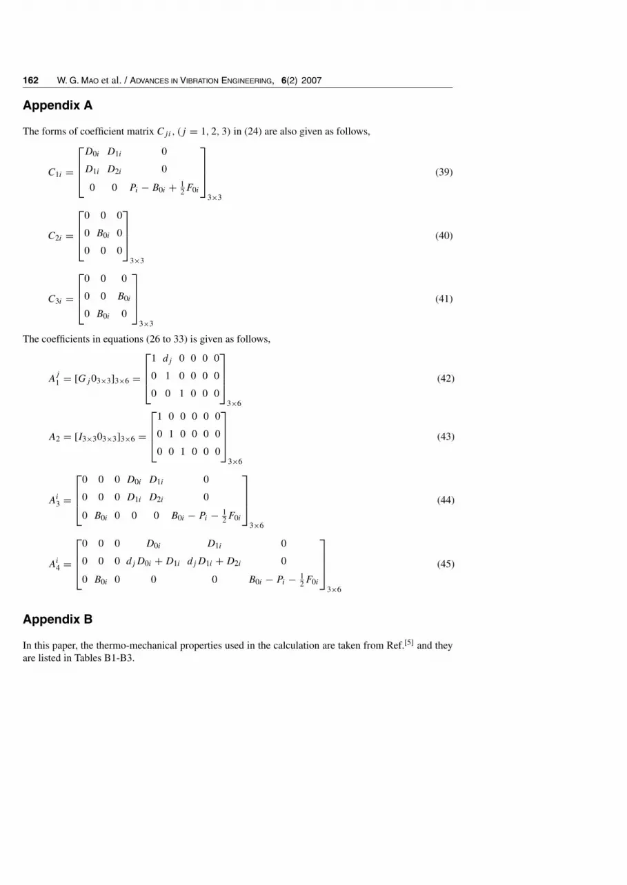
Appendix A
The forms of coefficient matrix Cji, (j = 1, 2, 3) in (24) are also given as follows,
C1i =
D0i D1i 0
D1i D2i 0
0 0 Pi − B0i + 12F0i
3×3
(39)
C2i =
0 0 0
0 B0i 0
0 0 0
3×3
(40)
C3i =
0 0 0
0 0 B0i
0 B0i 0
3×3
(41)
The coefficients in equations (26 to 33) is given as follows,
Aj
1 = [Gj03×3]3×6 =
1 dj 0 0 0 0
0 1 0 0 0 0
0 0 1 0 0 0
3×6
(42)
A2 = [I3×303×3]3×6 =
1 0 0 0 0 0
0 1 0 0 0 0
0 0 1 0 0 0
3×6
(43)
Ai3 =
0 0 0 D0i D1i 0
0 0 0 D1i D2i 0
0 B0i 0 0 0 B0i − Pi − 12F0i
3×6
(44)
Ai4 =
0 0 0 D0i D1i 0
0 0 0 djD0i +D1i djD1i +D2i 0
0 B0i 0 0 0 B0i − Pi − 12F0i
3×6
(45)
Appendix B
In this paper, the thermo-mechanical properties used in the calculation are taken from Ref.[5] and theyare listed in Tables B1-B3.

THERMO- MECHANICAL BUCKLING FAILURE 163
Table 1 Young’s modulus
Temperature Substrate Bond coat TGO TBC(0C) (GPa) (GPa) (GPa) (GPa)
20 220 200 400 48200 210 190 390 47400 190 175 380 44600 170 160 370 40800 155 145 355 34
1000 130 120 325 261100 120 110 320 22
Table 2 Poisson’s ratio
Temperature (0C) Substrate Bond coat TGO TBC20 0.31 0.30 0.23 0.10
200 0.32 0.30 0.23 0.10400 0.33 0.31 0.24 0.10600 0.33 0.31 0.24 0.11800 0.34 0.32 0.25 0.11
1000 0.35 0.33 0.25 0.121100 0.35 0.33 0.25 0.12
Table 3 Thermal expansion coefficients
Substrate Bond coat TGO TBCTemperature (0C) (×10−6/0C) (×10−6/0C) (×10−6/0C) (×10−6/0C)
20 14.8 13.6 8.0 9.0200 15.2 14.2 8.2 9.2400 15.6 14.6 8.4 9.6600 16.2 15.2 8.7 10.1800 16.9 16.1 9.0 10.8
1000 17.5 17.2 9.3 11.71100 18.0 17.6 9.6 12.2
References
[1] Brindley, W. J. and Miller, R. A., Thermal barrier coating life and isothermal oxidation of low-pressure plasma-sprayed bond coat alloys, Surface and Coatings Technology, Vol. 43–44(1),pp. 446–457, 1990.
[2] Miller, R. A., Life modeling of thermal barrier coatings for aircraft gas turbine engines, J. EngngGas Turbines Power, Vol. 111, pp. 301–305, 1989.
164 W. G. MAO et al. / ADVANCES IN VIBRATION ENGINEERING, 6(2) 2007
[3] Johnsen, B. P., Cruse, T. A., Miller, R. A. and Brindley, W. J., Compressive fatigue of a plasmasprayed ZrO2-8wt% Y2O3 and ZrO2-10wt% NiCrAlCoY TTBC, J. Engng. Mater. Tech., Vol. 117,pp. 305–310, 1995.
[4] Zhu, D. M. and Miller, R. A., Investigation of thermal fatigue behavior of thermal barrier coatingsystems, Surface Coating Tech., Vol. 94–95, pp. 94–101, 1997.
[5] Zhou, Y. C. and Hashida, T., Coupled effects of temperature gradient and oxidation on thermalstress in thermal barrier coating system, International Journal of Solids and Structures, Vol. 38,pp. 4235–4264, 2001.
[6] Teixeira, V., Andritschky, M., Fischer, W., Buchkremer, H. P. and Stoover, D., Analysis of residualstresses in thermal barrier coatings, Journal of Materials Processing Technology, Vol. 92–93,pp. 209–216, 1999.
[7] Widjaja, S., Limarga, A. M. and Yip, T. H., Modeling of residual stresses in a plasma-sprayedzirconiay alumina functionally graded-thermal barrier coating, Thin Solid Films, Vol. 434, pp. 216–227, 2003.
[8] Gell, M., Xie, L., Ma, X. Q., Jordan, E. H. and Padture, N. P., Highly durable thermal barriercoatings made by the solution precursor plasma spray process, Surface and Coatings Technology,Vol. 177–178, pp. 97–102, 2004.
[9] Hutchinson, J. W., He, M. Y. and Evans, A. G., The influence of imperfections on the nucleationand propagation of buckling driven delaminations, Journal of the Mechanics and Physics of Solids,Vol. 48, pp. 709–734, 2000.
[10] Chai, H., Babcock, C. D. and Knauss, W. G., One dimensional modeling of failure in laminatedplates by delamination buckling. Int. J. Solids Structures, Vol. 17(11), pp. 1069–1083, 1981.
[11] Bottega, W. G. and Maewal, A., Delamination buckling and growth in laminates. J. Appl. Mech.,Vol. 50, pp. 184–189, 1983.
[12] Yin, W. L., Axisymmetric buckling and growth of a circular delamination in a compressed laminate.Int. J. Solids Structures, Vol. 21(5), pp. 503–514, 1985.
[13] Kardomateas, G. A., The initial post buckling and growth behavior of internal delaminations incomposite plates. J. Appl. Mech., Vol. 60, pp. 903–910, 1993.
[14] Comiez, J. M. and Waas, A. M., Shahwan, K. W., Delamination buckling, experiment and analysis.Int. J. Solids Structures, Vol. 32(6), pp. 767–782, 1995.
[15] Yin, W. L., Thermomechanical buckling of delaminated composite laminates, Int. J. Solids Struc-tures, Vol. 35(20), pp. 2639–2653, 1998.
[16] Ma, L. S., Wang, T. J., Nonlinear bending and post-buckling of a functionally graded circular plateunder mechanical and thermal loadings, International Journal of Solids and Structures, Vol. 40,pp. 3311–3330, 2003.
Related Documents


