Thermal Transpiration-Based Microscale Thermal Transpiration-Based Microscale Combined Propulsion & Power Combined Propulsion & Power Generation Devices Generation Devices Francisco Ochoa, Jeongmin Ahn, Craig Eastwood, Paul Francisco Ochoa, Jeongmin Ahn, Craig Eastwood, Paul Ronney Ronney Dept. of Aerospace & Mechanical Engineering Dept. of Aerospace & Mechanical Engineering Univ. of Southern California, Los Angeles, CA Univ. of Southern California, Los Angeles, CA http://carambola.usc.edu/ Bruce Dunn Bruce Dunn Department of Materials Science and Engineering Department of Materials Science and Engineering University of California, Los Angeles, CA University of California, Los Angeles, CA

Thermal Transpiration-Based Microscale Combined Propulsion & Power Generation Devices Francisco Ochoa, Jeongmin Ahn, Craig Eastwood, Paul Ronney Dept.
Dec 22, 2015
Welcome message from author
This document is posted to help you gain knowledge. Please leave a comment to let me know what you think about it! Share it to your friends and learn new things together.
Transcript
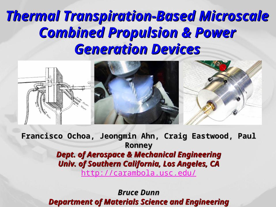
Thermal Transpiration-Based Thermal Transpiration-Based Microscale Combined Propulsion & Microscale Combined Propulsion &
Power Generation DevicesPower Generation Devices
Francisco Ochoa, Jeongmin Ahn, Craig Eastwood, Paul RonneyFrancisco Ochoa, Jeongmin Ahn, Craig Eastwood, Paul RonneyDept. of Aerospace & Mechanical EngineeringDept. of Aerospace & Mechanical EngineeringUniv. of Southern California, Los Angeles, CAUniv. of Southern California, Los Angeles, CA
http://carambola.usc.edu/
Bruce DunnBruce DunnDepartment of Materials Science and EngineeringDepartment of Materials Science and Engineering
University of California, Los Angeles, CAUniversity of California, Los Angeles, CA

Motivation - fuel-driven micro-propulsion systems Hydrocarbon fuels have numerous advantages over
batteries for energy storage ≈ 100 X higher energy density Much higher power / weight & power / volume of engine Nearly infinite shelf life More constant voltage, no memory effect, instant recharge Environmentally superior to disposable batteries
The challenge of micropropulsion … but converting fuel energy to thrust and/or
electricity with a small device has been challenging Many approaches use scaled-down macroscopic
combustion engines, but may have problems with Heat losses - flame quenching, unburned fuel & CO emissions Friction losses Sealing, tolerances, manufacturing, assembly Etc…
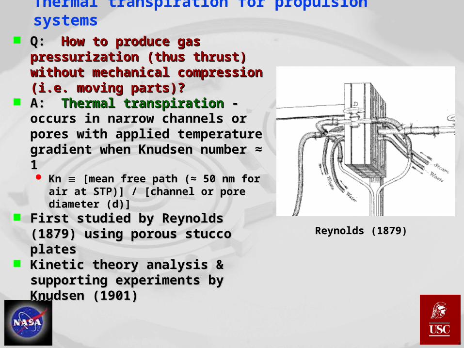
Thermal transpiration for propulsion systems Q: Q: How to produce gas How to produce gas
pressurization (thus thrust) without pressurization (thus thrust) without mechanical compression (i.e. mechanical compression (i.e. moving parts)?moving parts)?
A: A: Thermal transpirationThermal transpiration - - occurs in narrow channels or pores with applied temperature gradient when Knudsen number ≈ 1 Kn [mean free path (≈ 50 nm for air at
STP)] / [channel or pore diameter (d)] First studied by Reynolds (1879) First studied by Reynolds (1879)
using porous stucco platesusing porous stucco plates Kinetic theory analysis & Kinetic theory analysis &
supporting experiments by supporting experiments by Knudsen (1901)Knudsen (1901)
Reynolds (1879)

Modeling of thermal transpiration Net flow is the difference Net flow is the difference
between thermal creep at wall between thermal creep at wall and pressure-driven return flowand pressure-driven return flow
Analysis by Vargo et al. (1999):
Zero-flow pressure rise (Pno flow) increases with Kn but Mach # (M) decreases as Kn increases
Max. pumping power ~ MP at Kn ≈ 1
Length of channel (L) affects M but not Pmax
€
Pno flow
P1
=A
1− A /2;A ≡
ΔT
T f1(Kn)
€
M =1
2γ
d
L1−
ΔP
ΔPno flow
⎛
⎝ ⎜ ⎜
⎞
⎠ ⎟ ⎟ΔT
T
⎛
⎝ ⎜
⎞
⎠ ⎟f2(Kn)
0.01
0.1
1
0.1 1 10 100
f1(Kn)
f2(Kn)
Knudsen number
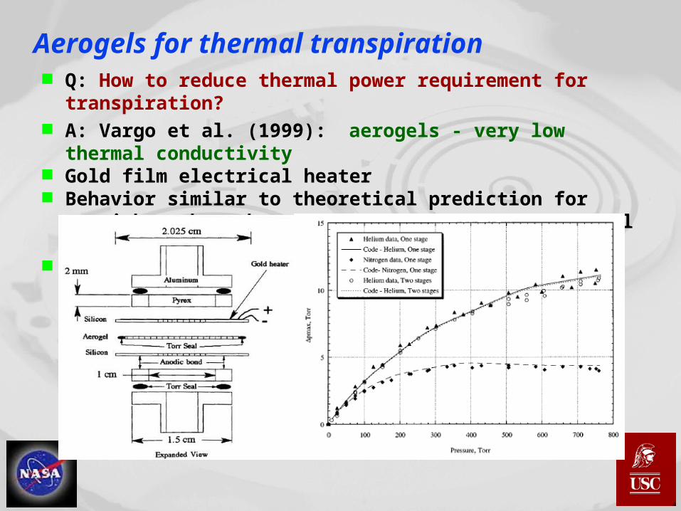
Aerogels for thermal transpiration Q: How to reduce thermal power requirement for transpiration? A: Vargo et al. (1999): aerogels - very low thermal conductivity Gold film electrical heater Behavior similar to theoretical prediction for straight tubes
whose length (L) is 1/10 of aerogel thickness! Can stage pumps for higher compression ratios

Aerogels Typical pore size 20 nm Low density (typ. 0.1 g/cm3) Thermal tolerance 500˚C Thermal conductivity can be
lower than interstitial gas! Typically made by
supercritical drying of silica gel using CO2 solvent

Jet or rocket engine with no moving parts Q: How to provide thermal power without electric heating as in
Vargo et al.? Answer: catalytic combustion! Can combine with nanoporous bismuth (thermoelectric material,
Dunn et al., 2000) for combined power generation & propulsion
Low-temperature
thermal guard
(electrically conductive,
non-catalytic)
Nanoporous Bi
membrane
Reactants in
(ambient T, P)
Products out
(higher T,
ambient P)
High-temperature
thermal guard
(catalytic)
Medium-temperature
thermal guard
(electrically conductive,
non-catalytic)
Si aerogel
membrane
Electrical
power out
Subsonic
nozzle
(converging
section only)
Low-temperature
thermal guard
(non-catalytic)
High-temperature
thermal guard
(catalytic)
Aerogel
membrane
Reactants
in (low T,
low P)
Products
out (high T,
high P)

Theoretical performance of aerogel rocket or jet engine
Can use usual propulsion relations to predict performance based on Vargo et al. model of thermal transpiration in aerogels
Non-dimensional TFSC of silica aerogel (k ≈ 0.0171 W/mK) only 2x - 4x worse than theoretical performance predictions for commercial gas turbine engines
Except as noted: Hydrocarbon-air, T1 = 300K, T2 = 600K, P1 = 1 atm, L = 100 µm, d = 100 nm
0
2
4
6
8
10
0 0.05 0.1 0.15 0.2 0.25Pressure rise / ambient pressure ( /P P
1)
Thrust specific fuel consumption
Pumping (%)efficiency
/ 1000Specific impulse( )seconds
Membrane exit / 10 ( / )velocity cm s
10Specific thrust x
0
2
4
6
8
10
0 50 100 150 200Mean pore diameter (d) (nm)
Thrust specific fuel consumption
Pumpingefficiency (%)
Membrane exitvelocity / 10 (cm/s)
Specific thrust x 10
Specific impulse / 1000(seconds)

Theoretical performance of aerogel rocket or jet engine
Membrane thickness affects thrust but not pressure rise, specific thrust or efficiency
Performance (both power & fuel economy) increases with temperature
Except as noted: Hydrocarbon-air, T1 = 300K, T2 = 600K, P1 = 1 atm, L = 100 µm, d = 100 nm
0
2
4
6
8
10
0 0.5 1 1.5 2Membrane thickness (L) (mm)
Thrust specific fuel consumption
Pumpingefficiency (%)
Membrane exitvelocity (cm/s)
Specific thrust x 10
Specific impulse/1000(seconds)
0
2
4
6
8
10
300 400 500 600 700 800 900Hot-side temperature (T
2) (K)
Thrust specific fuel consumption
Pumpingefficiency (%)
Membrane exitvelocity / 10 (cm/s)
Specific thrust x 10
Specific impulse / 1000(seconds)
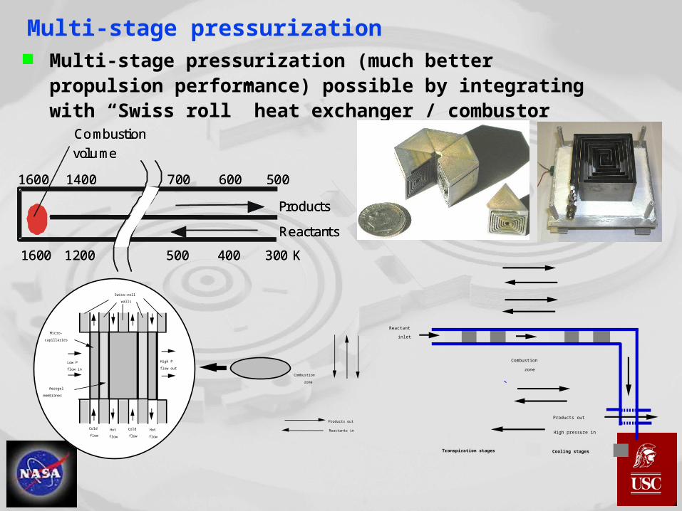
Multi-stage pressurization Multi-stage pressurization (much better propulsion
performance) possible by integrating with “Swiss roll” heat exchanger / combustor
Cold
flow
Hot
flow
Cold
flow
Hot
flow
Low P
flow in
High P
flow out
Swiss-roll
walls
Micro-
capillaries
Aerogel
membranes
Reactants in
Products out
Combustion
zone
Products out
Combustion
zone
Reactant
inlet
Transpiration stages Cooling stages
High pressure in
Products
Reactants
Combustion
volume
1600 1200 400 300 K500
1400 600 5007001600
Products
Reactants
Combustion
volume
1600 1200 400 300 K500
1400 600 5007001600

Feasibility testing Simple (“crude”?) test fixture built Electrical heating to date; catalytic
combustion testing starting Conventionally machined
commercial aerogel (L = 4 mm)
T h e r m a l g u a r d
T h e r m a l g u a r d
P t c a t a l y s t
A e r o g e l
C a t a l y s t s u p p o r t /
o u t l e t p l e n u m
I n l e t p l e n u m
O - r i n g s e a l s
Feasibility testing
0
10
20
30
40
50
60
70
0 20 40 60 80 100 120 140 160
ExperimentTheory/2
Temperature differential (˚C)
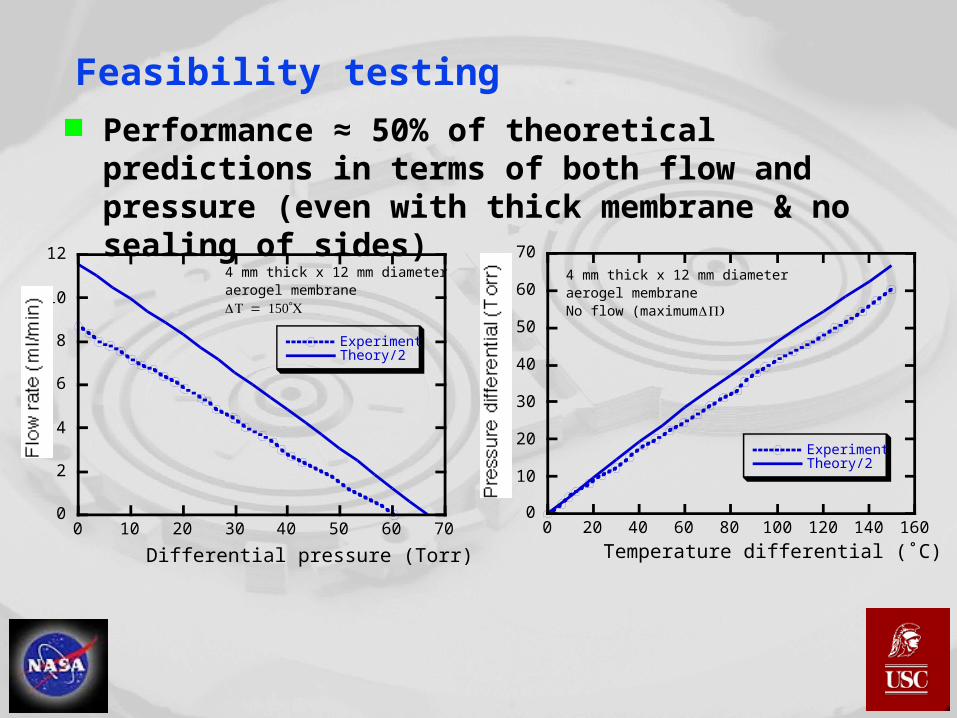
4 mm thick x 12 mm diameter aerogel membraneNo flow (maximum )P
Performance ≈ 50% of theoretical predictions in terms of both flow and pressure (even with thick membrane & no sealing of sides)
0
2
4
6
8
10
12
0 10 20 30 40 50 60 70
ExperimentTheory/2
Differential pressure (Torr)
4 mm thick x 12 mm diameter aerogel membrane = 150˚T C

Really really preliminary ideal design Airbreathing, single stage, TAirbreathing, single stage, TLL = 300K, T = 300K, THH = 600K, = 600K, P = 0.042 atm, 5.1 P = 0.042 atm, 5.1
W thermal powerW thermal power Hydrocarbon fuel, thrust 3.1 mN, specific thrust 0.36, IHydrocarbon fuel, thrust 3.1 mN, specific thrust 0.36, ISPSP = 2750 sec = 2750 sec With nanoporous Bi (ZT ≈ 0.39; 300K < T < 400K) could generate ≈ With nanoporous Bi (ZT ≈ 0.39; 300K < T < 400K) could generate ≈
100 mW of power, but with ≈ 30% less I100 mW of power, but with ≈ 30% less ISPSP & 2x weight & 2x weight
Mg alloy low-temperature
thermal guard
Reactants in (ambient T, P)
Products out (higher T, ambient P)
Metalization of hot-side of membrane
with Pt
Si aerogelmembrane
Subsonic nozzle
(Ti alloy)

Really really preliminary ideal design ComponentsComponents
Nanoporous membrane: 1 cmNanoporous membrane: 1 cm22 area, 100 µm thick, 100 nm area, 100 µm thick, 100 nm mean pore diameter, weight 0.00098 mNmean pore diameter, weight 0.00098 mN
Catalyst: Pt, deposited directly on high-T side of membrane Catalyst: Pt, deposited directly on high-T side of membrane (no need for hi-T thermal guard), 1 µm thick, weight 0.02 mN(no need for hi-T thermal guard), 1 µm thick, weight 0.02 mN
Low-temperature thermal guard: Magnesium Low-temperature thermal guard: Magnesium ZK60A-T5 alloy, 50 µm thick for 4x stress safety factor, weight 0.089 mN (less weight 0.089 mN (less if honeycomb; limited by strength, not conductivity), k = 120 if honeycomb; limited by strength, not conductivity), k = 120 W/mKW/mK
Case & nozzle: 5 mm long, titanium 811 alloy, k = 6 W/mK, Case & nozzle: 5 mm long, titanium 811 alloy, k = 6 W/mK, weight 0.114 mN weight 0.114 mN for 4x stress safety factor; hot-side radiative hot-side radiative loss 4% even for loss 4% even for aerogelaerogel = 1 = 1
Ideal performance Total weight 0.22 mN, Thrust/weight = 14 Hover time of vehicle (engine + fuel + Ti alloy fuel tank, no
payload) = 2 hours; flight time (lifting body, L/D = 5) = 10 hours

Other potential applications Could eliminate need for Could eliminate need for
pressurized rocket pressurized rocket propellant tanks - mass propellant tanks - mass savingssavings IISPSP with N with N22HH44 ≈ 100 sec ≈ 100 sec
Combined pump & valve Combined pump & valve (no (no T, no flow)T, no flow)
Propellant pumping for Propellant pumping for other micropropulsion other micropropulsion technologiestechnologies
Microscale pumping for gas analysis, pneumatic accumulators, cooling of dense microelectronics, …
Required low-temperature thermal guard (non-catalytic)
Aerogel membrane
(no catalyst)
Reactants in (low T, low P)
Products out(high T, high P)
Required high-temperature thermal guard (non-catalytic)
Catalyst
Non-reacting gas in (low T, low P)
Non-reacting gas out (high T, high P)
Aerogel membrane
(no catalyst)
Concept for co-pumping of non-reactive gas

Conclusions Nanoporous materials have many potential
applications for microthermochemical systems Thermal transpiration Insulation
Best non-vacuum insulation available Probably best insulation per unit weight for atmospheric
pressure applications Thermoelectric power generation (nanoporous Bi) Catalyst supports
Could form the basis of a micro/mesoscale jet/rocket engine with no moving parts
Aerogel MEMS fabrication developmentat UCLA
QuickTime™ and aGraphics decompressorare needed to see this picture.
Etching maskAlumina aerogelSacrificial siliconSilicon
Related Documents