Thermal Stress Temperature changes cause the body to expand or contract. The amount δ T , is given by where α is the coefficient of thermal expansion in m/m°C, L is the length in meter, and T i and T f are the initial and final temperatures, respectively in °C. For steel, α = 11.25 × 10 –6 / °C. If temperature deformation is permitted to occur freely, no load or stress will be induced in the structure. In some cases where temperature deformation is not permitted, an internal stress is created. The internal stress created is termed as thermal stress. For a homogeneous rod mounted between unyielding supports as shown, the thermal stress is computed as: deformation due to temperature changes; deformation due to equivalent axial stress; where σ is the thermal stress in MPa and E is the modulus of elasticity of the rod in MPa. If the wall yields a distance of x as shown, the following calculations will be made:

Welcome message from author
This document is posted to help you gain knowledge. Please leave a comment to let me know what you think about it! Share it to your friends and learn new things together.
Transcript
Thermal Stress Temperature changes cause the body to expand or contract. The amount δT, is given by
where α is the coefficient of thermal expansion in m/m°C, L is the length in meter, and
Ti and Tf are the initial and final temperatures, respectively in °C.
For steel, α = 11.25 × 10⁻⁶ / °C.
If temperature deformation is permitted to occur freely, no load or stress will be
induced in the structure. In some cases where temperature deformation is not
permitted, an internal stress is created. The internal stress created is termed as thermal
stress.
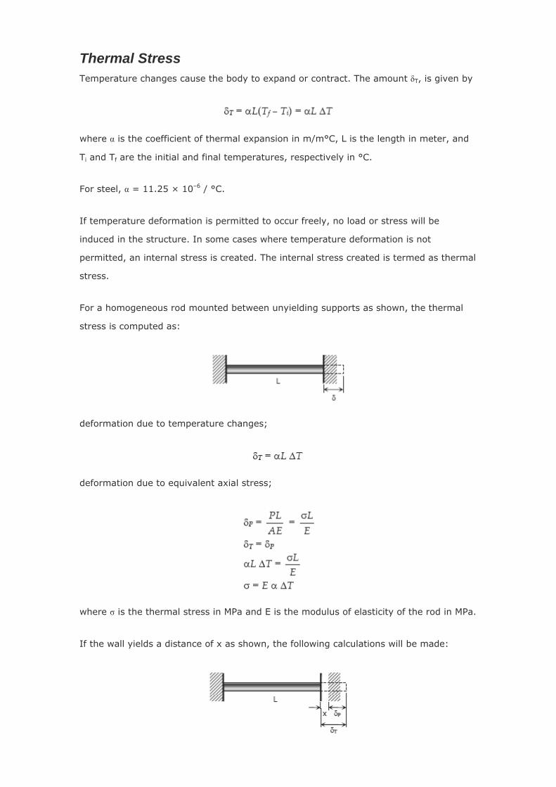
For a homogeneous rod mounted between unyielding supports as shown, the thermal
stress is computed as:
deformation due to temperature changes;
deformation due to equivalent axial stress;
where σ is the thermal stress in MPa and E is the modulus of elasticity of the rod in MPa.
If the wall yields a distance of x as shown, the following calculations will be made:
where σ represents the thermal stress.
Take note that as the temperature rises above the normal, the rod will be in
compression, and if the temperature drops below the normal, the rod is in tension.
Solved Problems in Thermal Stress
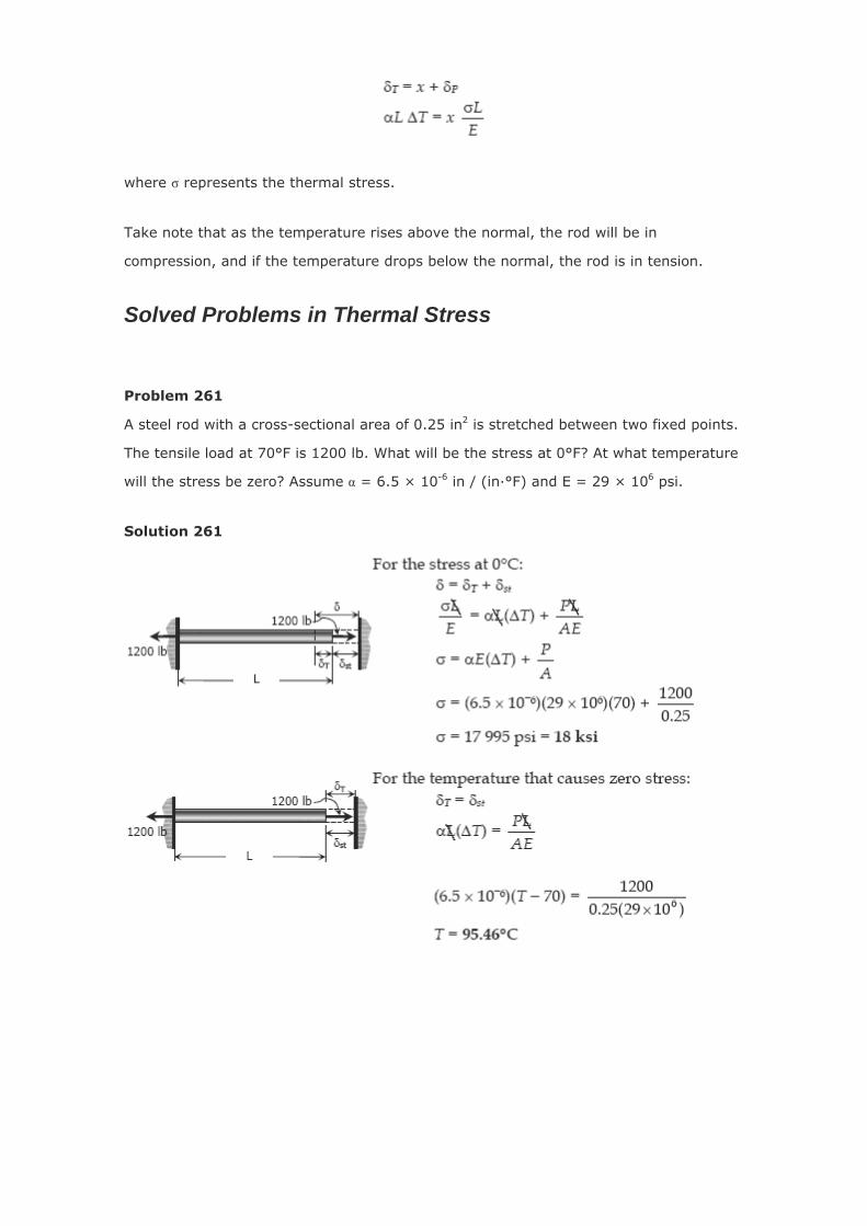
Problem 261
A steel rod with a cross-sectional area of 0.25 in2 is stretched between two fixed points.
The tensile load at 70°F is 1200 lb. What will be the stress at 0°F? At what temperature
will the stress be zero? Assume α = 6.5 × 10⁻⁶ in / (in·°F) and E = 29 × 106 psi.
Solution 261
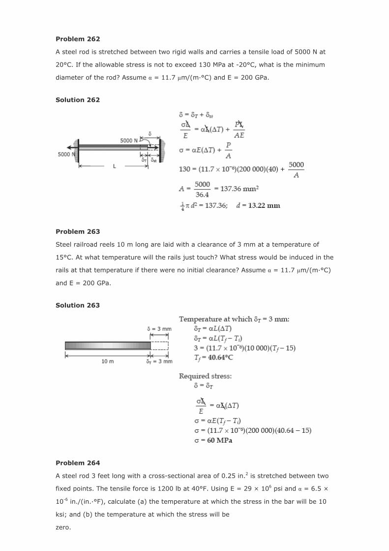
Problem 262
A steel rod is stretched between two rigid walls and carries a tensile load of 5000 N at
20°C. If the allowable stress is not to exceed 130 MPa at -20°C, what is the minimum
diameter of the rod? Assume α = 11.7 µm/(m·°C) and E = 200 GPa.
Solution 262
Problem 263
Steel railroad reels 10 m long are laid with a clearance of 3 mm at a temperature of
15°C. At what temperature will the rails just touch? What stress would be induced in the
rails at that temperature if there were no initial clearance? Assume α = 11.7 µm/(m·°C)
and E = 200 GPa.
Solution 263
Problem 264
A steel rod 3 feet long with a cross-sectional area of 0.25 in.2 is stretched between two
fixed points. The tensile force is 1200 lb at 40°F. Using E = 29 × 106 psi and α = 6.5 ×
10-6 in./(in.·°F), calculate (a) the temperature at which the stress in the bar will be 10
ksi; and (b) the temperature at which the stress will be
zero.
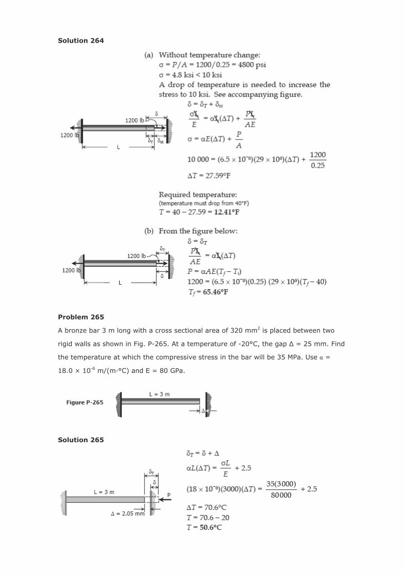
Solution 264
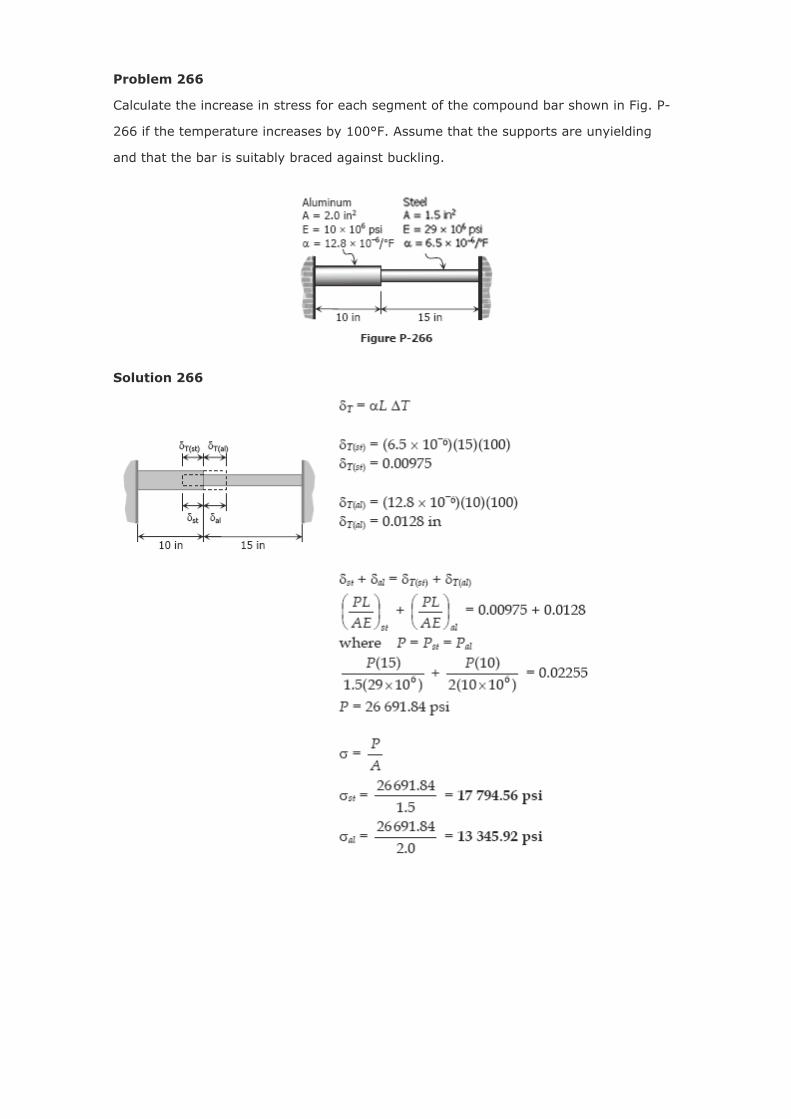
Problem 265
A bronze bar 3 m long with a cross sectional area of 320 mm2 is placed between two
rigid walls as shown in Fig. P-265. At a temperature of -20°C, the gap Δ = 25 mm. Find
the temperature at which the compressive stress in the bar will be 35 MPa. Use α =
18.0 × 10⁻⁶ m/(m·°C) and E = 80 GPa.
Solution 265
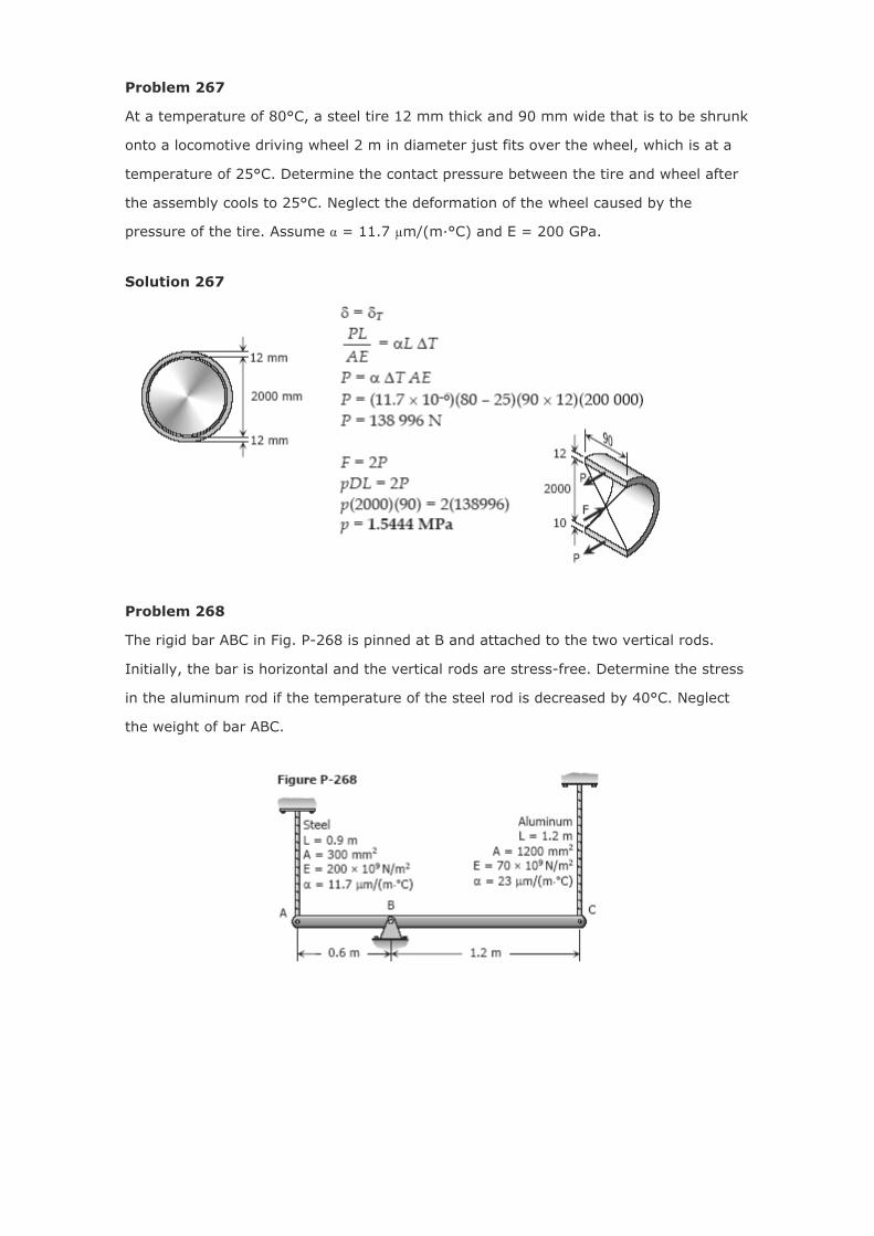
Problem 266
Calculate the increase in stress for each segment of the compound bar shown in Fig. P-
266 if the temperature increases by 100°F. Assume that the supports are unyielding
and that the bar is suitably braced against buckling.
Solution 266
Problem 267
At a temperature of 80°C, a steel tire 12 mm thick and 90 mm wide that is to be shrunk
onto a locomotive driving wheel 2 m in diameter just fits over the wheel, which is at a
temperature of 25°C. Determine the contact pressure between the tire and wheel after
the assembly cools to 25°C. Neglect the deformation of the wheel caused by the
pressure of the tire. Assume α = 11.7 µm/(m·°C) and E = 200 GPa.
Solution 267
Problem 268
The rigid bar ABC in Fig. P-268 is pinned at B and attached to the two vertical rods.
Initially, the bar is horizontal and the vertical rods are stress-free. Determine the stress
in the aluminum rod if the temperature of the steel rod is decreased by 40°C. Neglect
the weight of bar ABC.
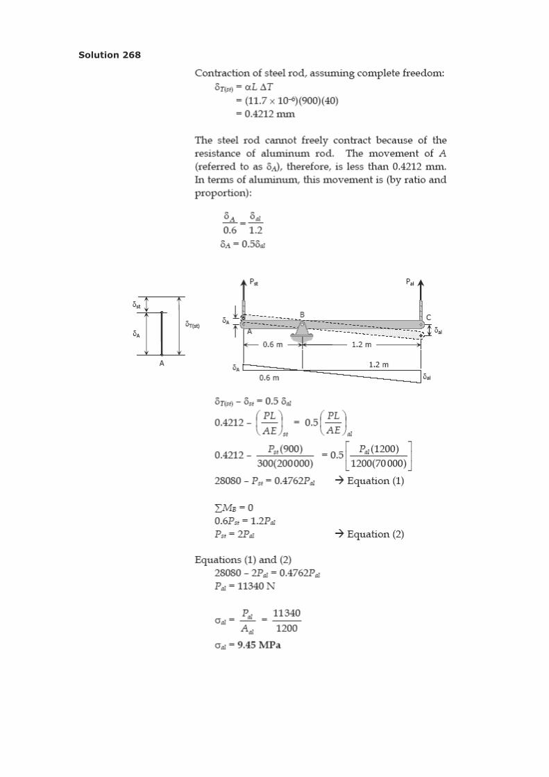
Solution 268
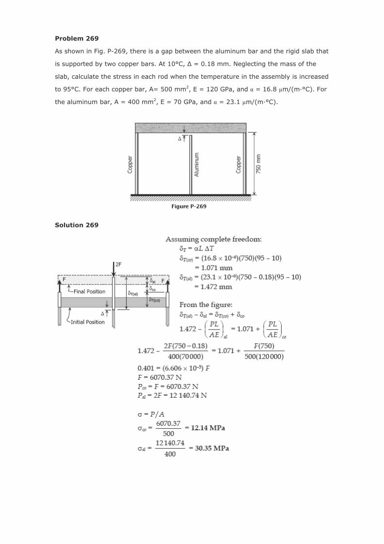
Problem 269
As shown in Fig. P-269, there is a gap between the aluminum bar and the rigid slab that
is supported by two copper bars. At 10°C, Δ = 0.18 mm. Neglecting the mass of the
slab, calculate the stress in each rod when the temperature in the assembly is increased
to 95°C. For each copper bar, A= 500 mm2, E = 120 GPa, and α = 16.8 µm/(m·°C). For
the aluminum bar, A = 400 mm2, E = 70 GPa, and α = 23.1 µm/(m·°C).
Solution 269
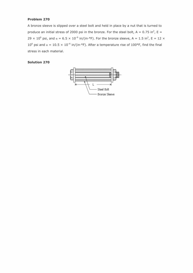
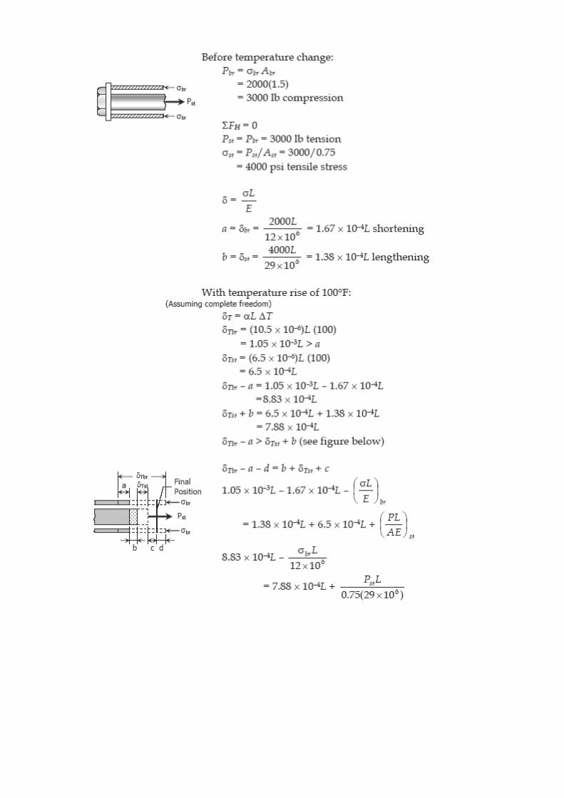
Problem 270
A bronze sleeve is slipped over a steel bolt and held in place by a nut that is turned to
produce an initial stress of 2000 psi in the bronze. For the steel bolt, A = 0.75 in2, E =
29 × 106 psi, and α = 6.5 × 10⁻⁶ in/(in·°F). For the bronze sleeve, A = 1.5 in2, E = 12 ×
106 psi and α = 10.5 × 10⁻⁶ in/(in·°F). After a temperature rise of 100°F, find the final
stress in each material.
Solution 270
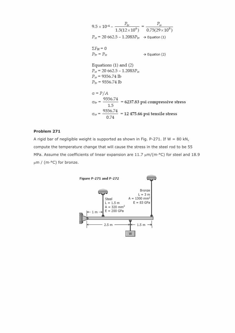
Problem 271
A rigid bar of negligible weight is supported as shown in Fig. P-271. If W = 80 kN,
compute the temperature change that will cause the stress in the steel rod to be 55
MPa. Assume the coefficients of linear expansion are 11.7 µm/(m·°C) for steel and 18.9
µm / (m·°C) for bronze.
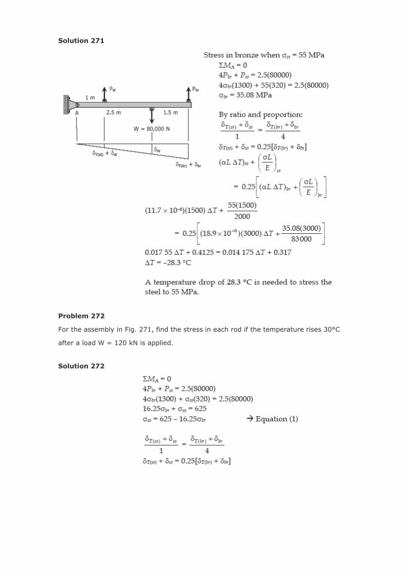
Solution 271
Problem 272
For the assembly in Fig. 271, find the stress in each rod if the temperature rises 30°C
after a load W = 120 kN is applied.
Solution 272
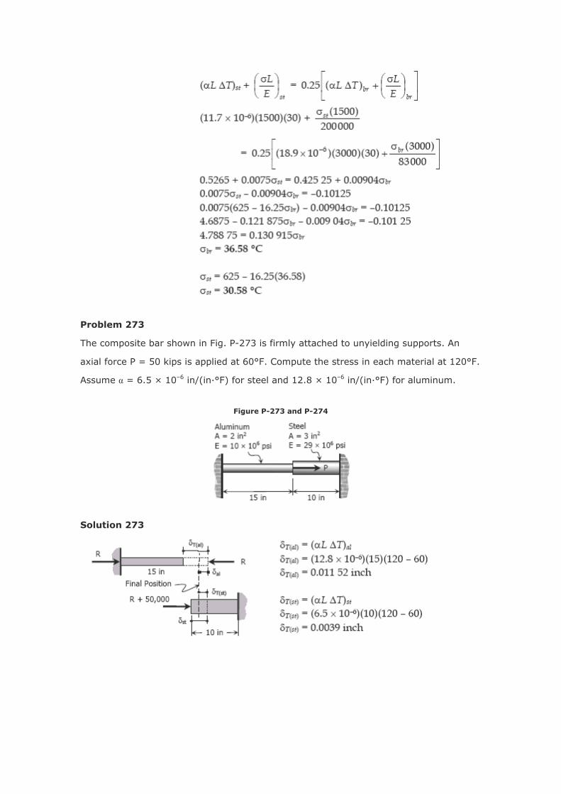
Problem 273
The composite bar shown in Fig. P-273 is firmly attached to unyielding supports. An
axial force P = 50 kips is applied at 60°F. Compute the stress in each material at 120°F.
Assume α = 6.5 × 10⁻⁶ in/(in·°F) for steel and 12.8 × 10⁻⁶ in/(in·°F) for aluminum.
Figure P-273 and P-274
Solution 273
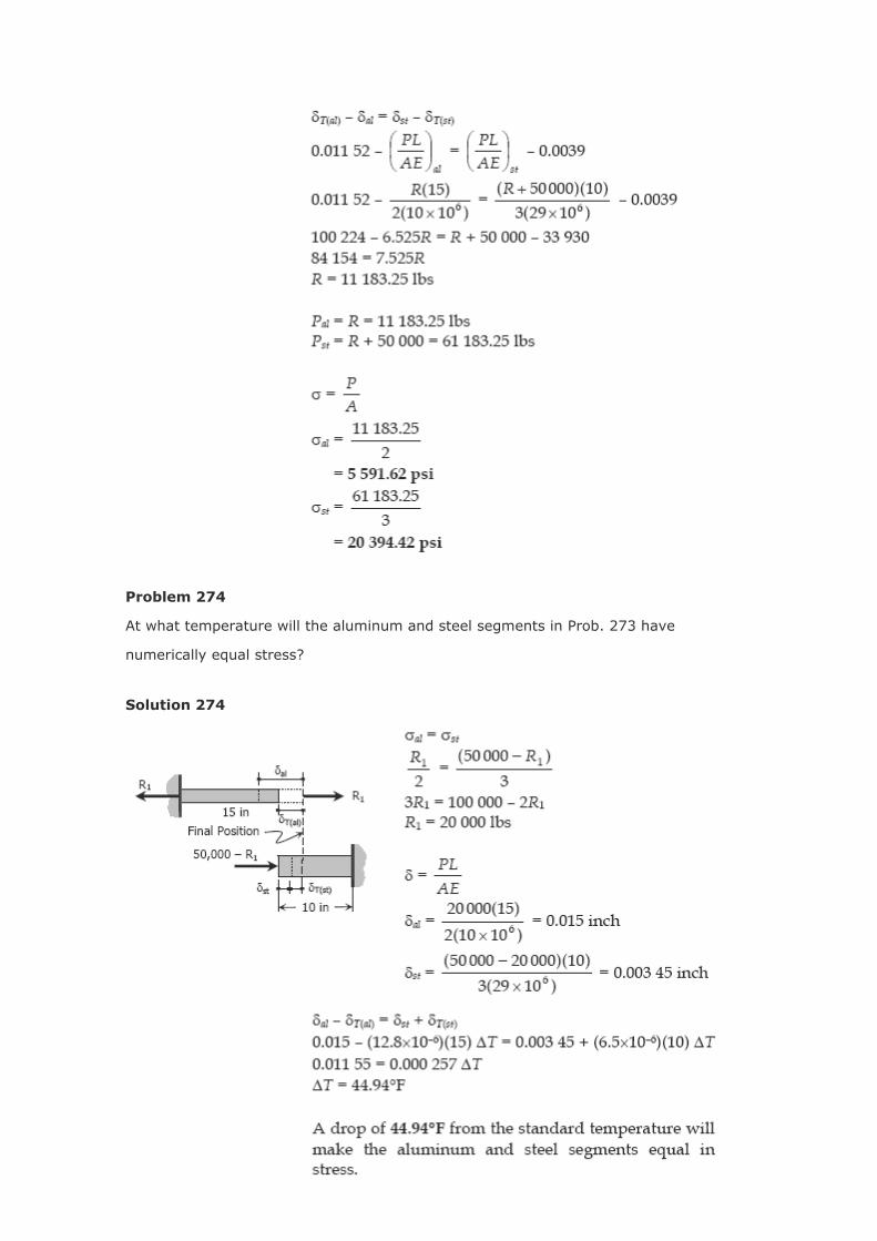
Problem 274
At what temperature will the aluminum and steel segments in Prob. 273 have
numerically equal stress?
Solution 274
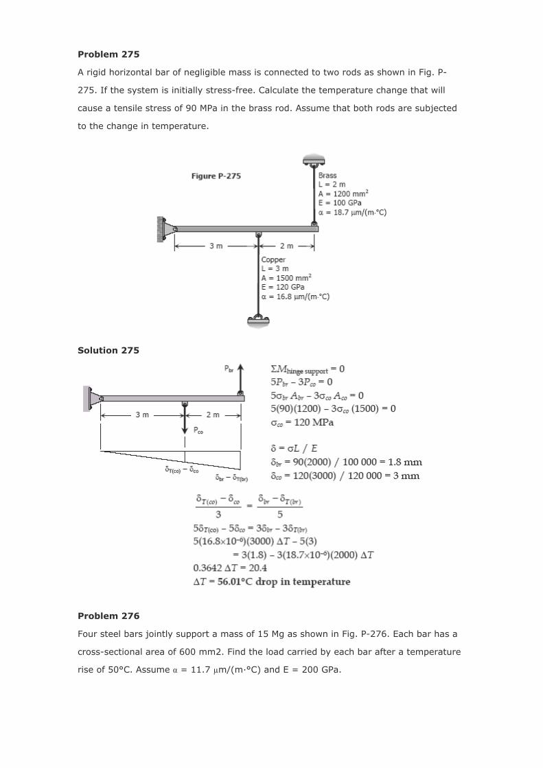
Problem 275
A rigid horizontal bar of negligible mass is connected to two rods as shown in Fig. P-
275. If the system is initially stress-free. Calculate the temperature change that will
cause a tensile stress of 90 MPa in the brass rod. Assume that both rods are subjected
to the change in temperature.
Solution 275
Problem 276
Four steel bars jointly support a mass of 15 Mg as shown in Fig. P-276. Each bar has a
cross-sectional area of 600 mm2. Find the load carried by each bar after a temperature
rise of 50°C. Assume α = 11.7 µm/(m·°C) and E = 200 GPa.
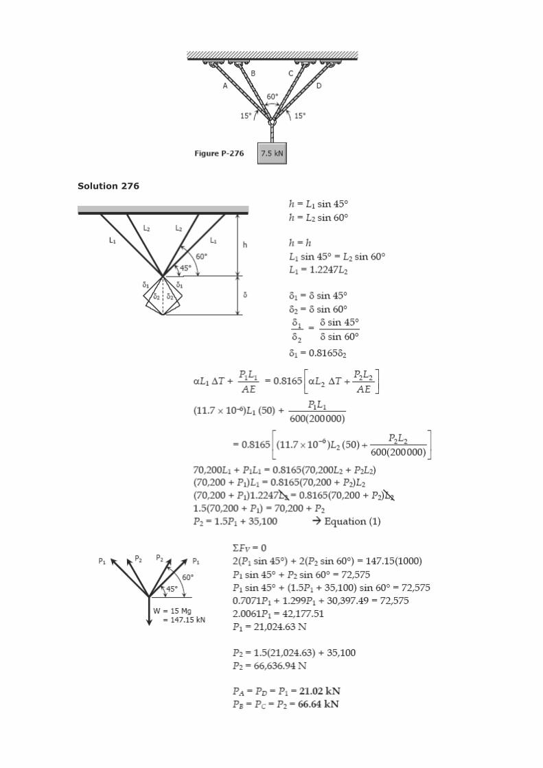
Solution 276
Related Documents