Presented by: Akbar Ahmad Bhupesh Kumar Pal 2011PE09 2011PE05 9/28/2013 MNNIT 1

Welcome message from author
This document is posted to help you gain knowledge. Please leave a comment to let me know what you think about it! Share it to your friends and learn new things together.
Transcript

7/28/2019 Thermal Power Plant Introduction
http://slidepdf.com/reader/full/thermal-power-plant-introduction 1/51
Presented by: Akbar Ahmad Bhupesh Kumar Pal
2011PE09 2011PE05
9/28/2013MNNIT 1
7/28/2019 Thermal Power Plant Introduction
http://slidepdf.com/reader/full/thermal-power-plant-introduction 2/51
INTRODUCTION TO ESSAR-MAHAN POWER PLANT
1200-MW (2x600 MW) coal-fired pit-head power plant
Located in Singrauli district, Madhya Pradesh
CONSULTANTS
ESSAR ENGINEERING SERVICES LTD.
TCE CONSULTING ENGINEERS LTD.
SUPPLIER
ESSAR CONSTRUCTION (I) LTD.
EBOP ( Electrical Balancing of Plant )
ALSTOM T&D INDIA LTD
9/28/2013MNNIT 2

7/28/2019 Thermal Power Plant Introduction
http://slidepdf.com/reader/full/thermal-power-plant-introduction 3/51
No. of Lines: 4
Line 1 & 2: VINDHYACHAL- KORBA LINE
Line 3 & 4: MAHAN- SIPAT LINE
Coal Source
Mahan Coal Block located at 4 Km distance from site allottedto Joint venture Company Mahan Coal Ltd formed between Essar Power &
Hindalco.
Water Source
Rihand water Reservoir
9/28/2013MNNIT 3

7/28/2019 Thermal Power Plant Introduction
http://slidepdf.com/reader/full/thermal-power-plant-introduction 4/51
Step wise operations in a thermal
power plant are as follows:- Coal is used as a fuel to boil
the water.
Water is boiled to form
pressurized steam.
Pressurized steam is the forcethat cause the turbine to
rotate at a very high speed.
Low pressure steam after
pushing through the turbine
goes into the condenser.
Condenser – the place where
the steam is condensed back it
it’s liquid form .Then theprocess is repeated.
9/28/2013MNNIT 4
Operations In Thermal PowerStation
7/28/2019 Thermal Power Plant Introduction
http://slidepdf.com/reader/full/thermal-power-plant-introduction 5/51
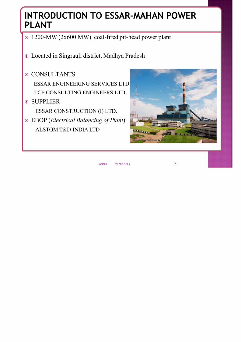
BASIC OPERATION :
A thermal power plant basicallyworks on Rankine cycle.
.
9/28/2013MNNIT 5
7/28/2019 Thermal Power Plant Introduction
http://slidepdf.com/reader/full/thermal-power-plant-introduction 6/51
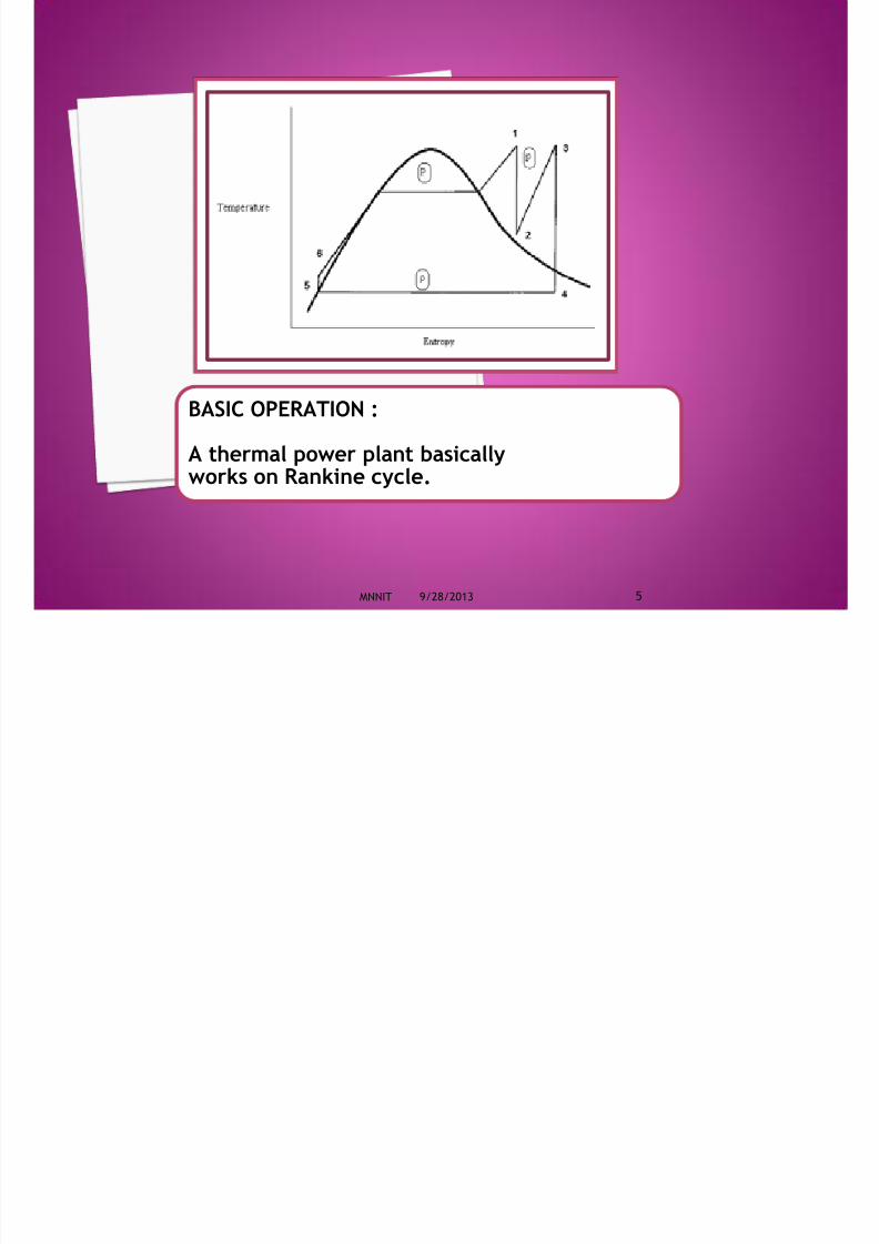
A thermal power station isa power plant in which the primemover is steam driven.
Water is heated, turns into steamand spins a steam turbine whichdrives an electrical generator .
After it passes through theturbine, the steam iscondensed in a condenser andrecycled to where it was heated;
this is known as a Rankine cycle. The greatest variation in the
design of thermal power stationsis due to the different fuelsources.
Some prefer to use theterm energy center because suchfacilities convert forms of heatenergy into electrical energy.
9/28/2013MNNIT 6
Definition Of Thermal Power Station
7/28/2019 Thermal Power Plant Introduction
http://slidepdf.com/reader/full/thermal-power-plant-introduction 7/519/28/2013MNNIT 7
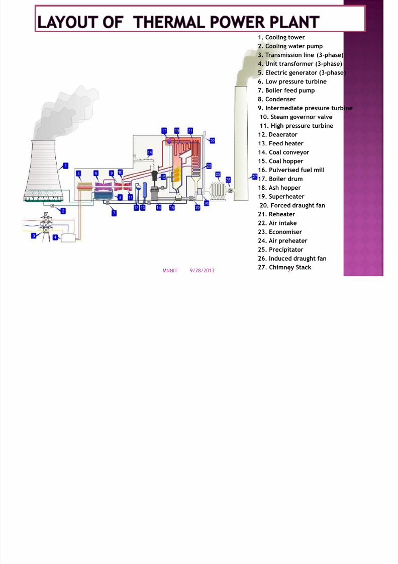
1. Cooling tower
2. Cooling water pump
3. Transmission line (3-phase)
4. Unit transformer (3-phase)5. Electric generator (3-phase)
6. Low pressure turbine
7. Boiler feed pump
8. Condenser
9. Intermediate pressure turbine
10. Steam governor valve
11. High pressure turbine
12. Deaerator
13. Feed heater
14. Coal conveyor
15. Coal hopper
16. Pulverised fuel mill
17. Boiler drum
18. Ash hopper
19. Superheater
20. Forced draught fan
21. Reheater
22. Air intake
23. Economiser
24. Air preheater
25. Precipitator
26. Induced draught fan27. Chimney Stack

7/28/2019 Thermal Power Plant Introduction
http://slidepdf.com/reader/full/thermal-power-plant-introduction 8/51
COAL FEEDING SYSTEM
Coal is conveyed through rail wagon from out side of
plant and through conveyor system collected in
hopper
and grinded to a very fine powder by large metalspheres in the pulverized fuel mill.
Conveyor Coal Hopper
Pulverized Mill
Wagon Tippler
7/28/2019 Thermal Power Plant Introduction
http://slidepdf.com/reader/full/thermal-power-plant-introduction 9/51
Pulverized coal is put in boiler furnace in which water is heated and circulateduntil the water is turned in to steam at the required pressure
The steam then rises up and gets collected inside the boiler drum. The boiler ismade up of carbon steel. Boiler drum is cylindrical drum like structure containsmixture of water and steam.
The steam that comes out of the boiler with increased temperature andpressure.
Types of boilers are natural circulation, dry bottom, and tangential fired,radiant heat type
Boiler in this plant is four corners tangential-firing type
SUPERHEATER: Super heater is a component of a steam-generating unit in whichsteam, after it has left the boiler drum, is heated above its saturationtemperature
REHEATER : Reheater is also steam boiler component in which heat is added tothis intermediate-pressure steam, which has given up some of its energy inexpansion through the high-pressure turbine.
DEARATOR: A deaerator is a device that is widely used for the removal of oxygen
and other dissolved gases from the feedwater to steam-generating boiler.

7/28/2019 Thermal Power Plant Introduction
http://slidepdf.com/reader/full/thermal-power-plant-introduction 10/51
Manufacturer Harbin Boiler Group Co. Ltd (HBC)
Operational Parameters
BMCR TMCR
Superheater Outlet Steam Flow rate Tph 2060 1875.12 Steam Pressure Mpa (g) 17.5 17.34 Steam Temp oC 541 541
Reheater Inlet Steam Flow rate Tph 1725.78 1579.6 Steam Pressure Mpa (g) 4.006 3.662 Steam Temp oC 335.1 325.3
Reheater Outlet Steam Pressure Mpa (g) 3.816 3.477 Steam Temp oC 541 541
Feed Water Temp oC 281.2 275.1 Flue Gas at Air Preheater Outlet Efficiency % 87.25 Heating Surface Area m2
66970

7/28/2019 Thermal Power Plant Introduction
http://slidepdf.com/reader/full/thermal-power-plant-introduction 11/51
A steam turbine is a device that extracts thermal energy frompressurized steam and uses it to do mechanical work on a rotating
output shaft
The turbine is used to drive an electrical generator
9/28/2013MNNIT 11

7/28/2019 Thermal Power Plant Introduction
http://slidepdf.com/reader/full/thermal-power-plant-introduction 12/51

7/28/2019 Thermal Power Plant Introduction
http://slidepdf.com/reader/full/thermal-power-plant-introduction 13/51
CONDENSER :
Steam after rotating steam turbine comes to condenser. Thesecondensers are heat exchangers which convert steam from itsgaseous to its liquid state. In so doing, the latent heat of steamis given out inside the condenser.
COOLING TOWERS :
The condensate water after condensation is initially at hightemperature. This hot water is passed to cooling towers. It isa tower in which atmospheric air circulates in direct or indirectcontact with warm water and the water is thereby cooled. Water,acting as the heat-transfer fluid, gives up heat to atmospheric
air, and thus cooled.
9/28/2013MNNIT 13

7/28/2019 Thermal Power Plant Introduction
http://slidepdf.com/reader/full/thermal-power-plant-introduction 14/51
ECONOMISER :
Flue gases coming out of the boiler carry lot of heat.
Function of economiser is to recover some of the heatfrom the heat carried away in the flue gases up thechimney and utilize for heating the feed water to theboiler. It is placed in the passage of flue gases in betweenthe exit from the boiler and the entry to the chimney.
AIR PREHEATER :
The remaining heat of flue gases is utilised by airpreheater. It is a device used in steam boilers to transferheat from the flue gases to the combustion air before theair enters the furnace
9/28/2013MNNIT 14

7/28/2019 Thermal Power Plant Introduction
http://slidepdf.com/reader/full/thermal-power-plant-introduction 15/51
ELECTROSTATIC PRECIPITATOR :
It is a device which removes dust or other finely dividedparticles from flue gases by charging the particlesinductively with an electric field, then attracting them tohighly charged collector plates.
SMOKE STACK (CHIMNEY) :
A chimney is a system for venting hot fluegases or smoke from a boiler, stove, furnace or fireplace tothe outside atmosphere. They are typically almost verticalto ensure that the hot gases flow smoothly, drawing air into
the combustion through the chimney effect
9/28/2013MNNIT 15

7/28/2019 Thermal Power Plant Introduction
http://slidepdf.com/reader/full/thermal-power-plant-introduction 16/51
The transformation of mechanical energy into electrical
energy is carried out by the generator. When the rotor is energised the flux lines emitted by it are
cut by the stator windings which induces an emf in them
given by
E = 4.44 f Φ N
9/28/2013MNNIT 16

7/28/2019 Thermal Power Plant Introduction
http://slidepdf.com/reader/full/thermal-power-plant-introduction 17/51
Manufacturer Harbin Generator Co. Ltd. Rated Output 600 MW 705.88 MVA Phase 3 Frequency Hz 50 Speed rpm 3000 Stator Winding Type YY Stator Current A 20377 Stator Voltage KV 20 Power Factor 0.85 (lag)
Cooling mode Stator winding Water Rotor winding Hydrogen
9/28/2013MNNIT 17
Generator Frame volume(including rotor) m³ 110 Generator Rotor Weight t 66.5 Generator Stator Weight t 300 Generator Total Weight t 465 Excitation type static excitation
7/28/2019 Thermal Power Plant Introduction
http://slidepdf.com/reader/full/thermal-power-plant-introduction 18/51
The transformer is a device that transfers electrical energy from
one electrical circuit to another through the medium of magneticfield and without the change of frequency.
The two windings are not connected electrically but coupled
magnetically. Its efficiency is in the range of 97 to 98 %.
Main Transformers
Generator Transformer (GT):-
-This is a step up transformer.
- This supply gets its primary supply from generator and its
secondary
supplies the switchyard from where it is transmitted to grid.
- primary is in STAR and secondary is in DELTA
- GT 1 & GT 2 - 3x1PH, 250MVA & there are two GT in this plant

7/28/2019 Thermal Power Plant Introduction
http://slidepdf.com/reader/full/thermal-power-plant-introduction 19/51
GENERATOR TRANSFORMER Make AREVA Type Double Wound Service Outdoor
No. of Windings Per Phase
02
No. of Phases 01 Rated Power (HV) 250 MVA Rated Power (LV) 250 MVA
Rated Voltage at No Load(HV) 420/ √ 3 Kv Rated Voltage at No Load
(LV) 20 Kv Rated Line Current (HV) 1029.8 A Rated Line Current (LV)
12500 A
Rated Frequency 50 Hz Station Transformer (ST):-- It is a step down transformer
-same rating as the generator transformer
- primary is connected in delta and secondary in star
-These are 2 in number each of 70 MVA.

7/28/2019 Thermal Power Plant Introduction
http://slidepdf.com/reader/full/thermal-power-plant-introduction 20/51
STATION TRANSFORMER Make AREVA Type Double Wound Service Outdoor
No. of Windings Per Phase 02 No. of Phases 03 Rated Power (PRI) 70 MVA Rated Power (SEC 1) 25 MVA Rated Power (SEC 2) 45 MVA Rated Voltage at No Load (HV) 20 kV Rated Voltage at No Load (SEC 1) 34.5 kV Rated Voltage at No Load (SEC 2) 11.5 kV Rated Line Current (PRI) 2023.12 A Rated Line Current (SEC 1) 418.87 A Rated Line Current (SEC 2) 2261.87 A Rated Frequency 50 Hz Unit Auxiliary Transformer (UT):
-This is a step down transformer.
-The primary receives from generator and secondary supplies a 6.6 KV bus
-This is oil cooled
-These are 4 in number

7/28/2019 Thermal Power Plant Introduction
http://slidepdf.com/reader/full/thermal-power-plant-introduction 21/51
UNIT TRANSFORMER Make AREVA Type Double Wound
No. of Windings Per Phase 02 No. of Phases 03 Rating Rated Power (HV) 36/ 45 MVA Rated Power (LV) 36/ 45 MVA Rated Voltage at No Load (HV) 20 kV Rated Voltage at No Load (LV) 11.5 kV Rated Line Current (HV) 1040.46/ 1300.58 A Rated Line Current (LV) 1809.49/ 2261.87 A Rated Frequency 50 Hz

7/28/2019 Thermal Power Plant Introduction
http://slidepdf.com/reader/full/thermal-power-plant-introduction 22/51
Raw Water Pump HouseRaw Water Reservoir
Chemical
House
Pipe Rack PR-32
CascadeAerator
Sludge Pit
HRSCC -1B
Back WashPit
HRSCC – 1A
Rapid Gravity SandFilter
Filter Water Tank & PumpHouse
Overview of Under construction BOP- Raw Water System
9/28/2013MNNIT 22
7/28/2019 Thermal Power Plant Introduction
http://slidepdf.com/reader/full/thermal-power-plant-introduction 23/51
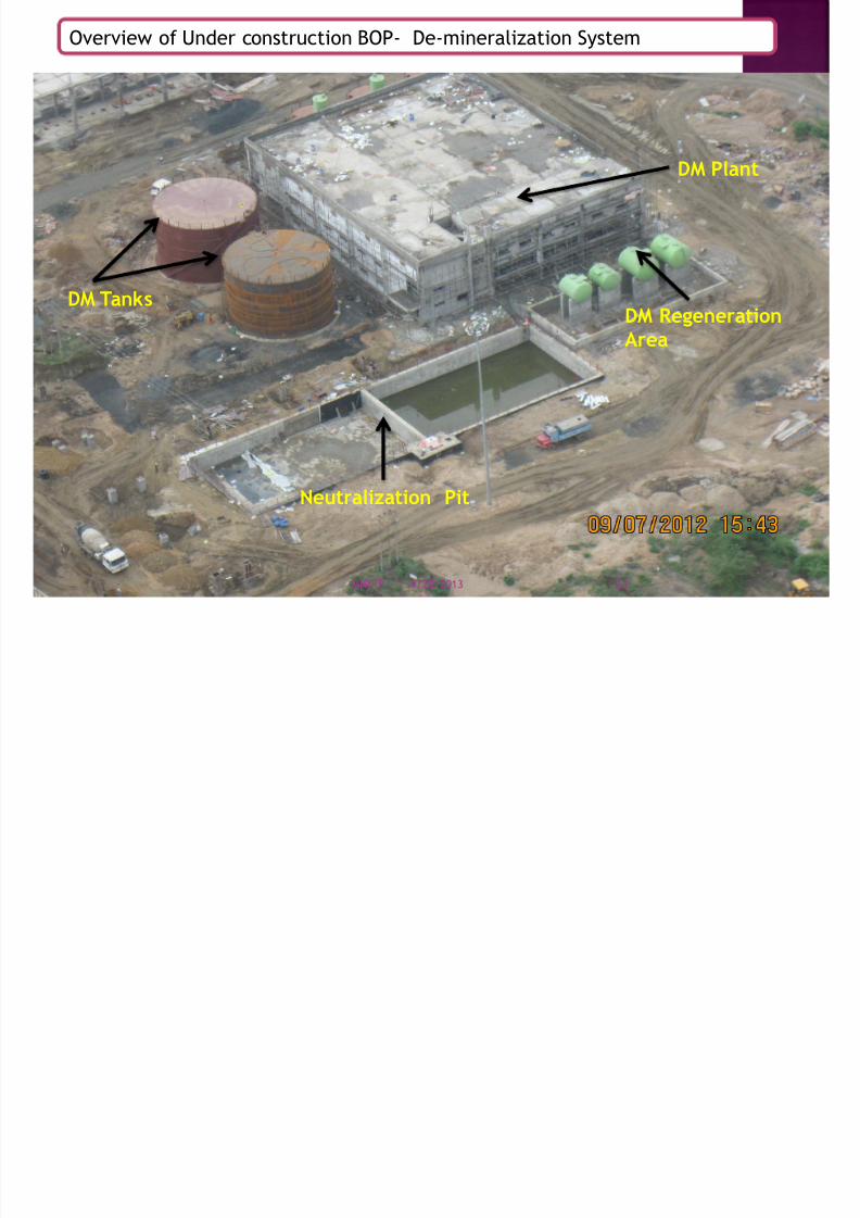
DM Plant
DM Tanks
Neutralization Pit
DM RegenerationArea
Overview of Under construction BOP- De-mineralization System
9/28/2013MNNIT 23

7/28/2019 Thermal Power Plant Introduction
http://slidepdf.com/reader/full/thermal-power-plant-introduction 24/51
Wagon Tippler 1 &2
Wagon Tippler 3 &4Sloping ConveyorTunnel
TP-3
Conveyor 3A/3B
CHP Retaining Wall
Overview of Under construction BOP- Coal Feeding System
9/28/2013MNNIT 24

7/28/2019 Thermal Power Plant Introduction
http://slidepdf.com/reader/full/thermal-power-plant-introduction 25/51
Crusher House
TP-4
TP-5
Conveyor4A/4B Conveyor 5A/5B
Stacker Reclaimer
Coal Stock Yard
Overview of Under construction BOP- Coal Feeding System
9/28/2013MNNIT 25

7/28/2019 Thermal Power Plant Introduction
http://slidepdf.com/reader/full/thermal-power-plant-introduction 26/51
Overview of Under construction Boiler System
9/28/2013MNNIT 26

7/28/2019 Thermal Power Plant Introduction
http://slidepdf.com/reader/full/thermal-power-plant-introduction 27/51
9/28/2013MNNIT 27

7/28/2019 Thermal Power Plant Introduction
http://slidepdf.com/reader/full/thermal-power-plant-introduction 28/51
9/28/2013MNNIT 28

7/28/2019 Thermal Power Plant Introduction
http://slidepdf.com/reader/full/thermal-power-plant-introduction 29/51
9/28/2013MNNIT 29
7/28/2019 Thermal Power Plant Introduction
http://slidepdf.com/reader/full/thermal-power-plant-introduction 30/51
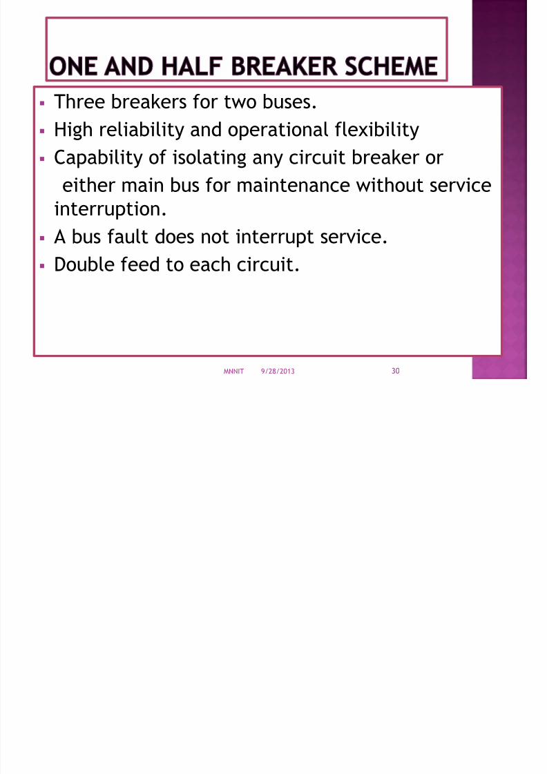
Three breakers for two buses.
High reliability and operational flexibility
Capability of isolating any circuit breaker or
either main bus for maintenance without serviceinterruption.
A bus fault does not interrupt service.
Double feed to each circuit.
9/28/2013MNNIT 30

7/28/2019 Thermal Power Plant Introduction
http://slidepdf.com/reader/full/thermal-power-plant-introduction 31/51
Bus Ducts Circuit Breaker
Capacitive Voltage Transformer (CVT)
Electro Magnetic Voltage Transformer(EMVT)
Isolators/Disconnectors Earth Switches
Current Transformers
Wave trap
Surge/Lightning Arrestors
9/28/2013MNNIT 31

7/28/2019 Thermal Power Plant Introduction
http://slidepdf.com/reader/full/thermal-power-plant-introduction 32/51
Originally developed in the 1960s, Isolated phase bus duct (IPB or
IPBD), is a method of construction for circuits carrying very largecurrents, typically between a generator and Generator Step-Up
Transformer
Conductors are rolled hollow aluminum tubes, supported within the
enclosure on porcelain or polymer insulators
9/28/2013MNNIT 32

7/28/2019 Thermal Power Plant Introduction
http://slidepdf.com/reader/full/thermal-power-plant-introduction 33/51
9/28/2013MNNIT 33
Also of two types-
(a) segregated phase bus duct
(b) non-segregated phase bus duct
7/28/2019 Thermal Power Plant Introduction
http://slidepdf.com/reader/full/thermal-power-plant-introduction 34/51
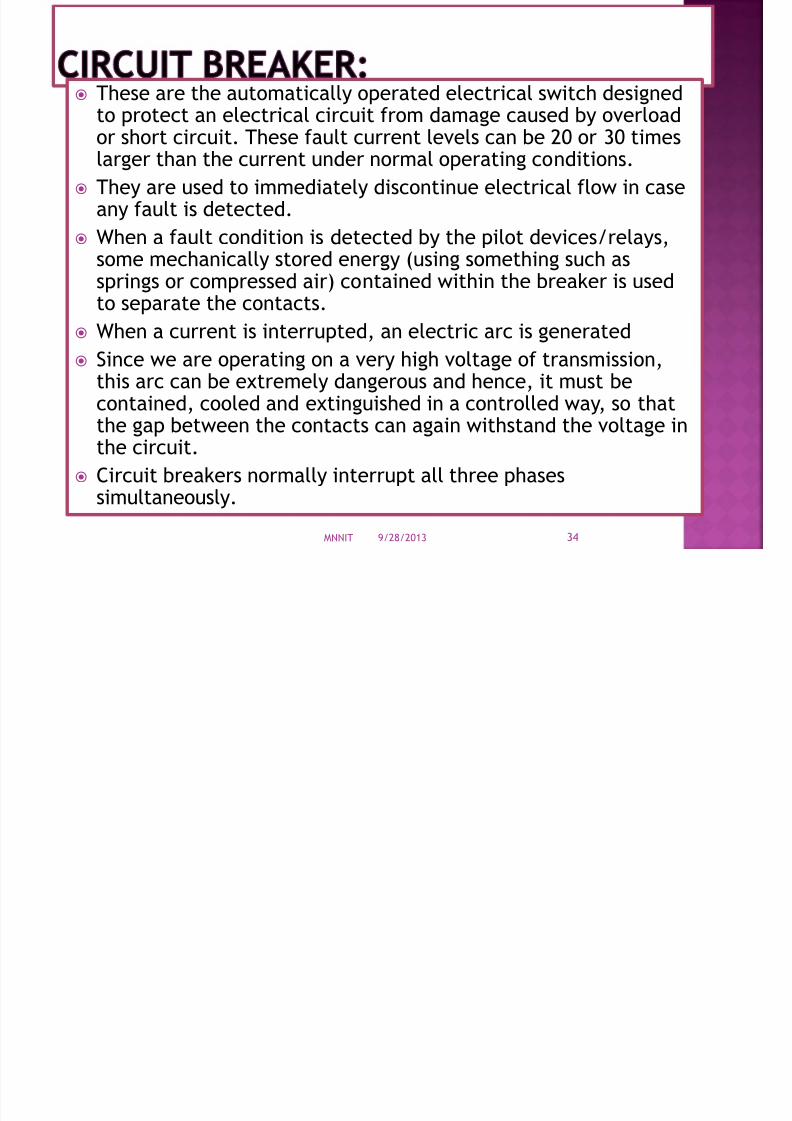
These are the automatically operated electrical switch designedto protect an electrical circuit from damage caused by overload
or short circuit. These fault current levels can be 20 or 30 timeslarger than the current under normal operating conditions.
They are used to immediately discontinue electrical flow in caseany fault is detected.
When a fault condition is detected by the pilot devices/relays,
some mechanically stored energy (using something such assprings or compressed air) contained within the breaker is usedto separate the contacts.
When a current is interrupted, an electric arc is generated
Since we are operating on a very high voltage of transmission,
this arc can be extremely dangerous and hence, it must becontained, cooled and extinguished in a controlled way, so thatthe gap between the contacts can again withstand the voltage inthe circuit.
Circuit breakers normally interrupt all three phasessimultaneously.
9/28/2013MNNIT 34

7/28/2019 Thermal Power Plant Introduction
http://slidepdf.com/reader/full/thermal-power-plant-introduction 35/51
The insulating fluids commonly used in circuit breakers are:
Compressed air
Oil which produces hydrogen for arc excitation.
Vacuum
Sulphur hexafluorides (SF6 )
Circuit Breaker used at ESSAR-MAHAN switchyard :
SF6 Circuit Breaker – manufactured by ALSTOM
SPECIFICATION
Rated Voltage: 420 kV Rated Normal Current: 3000 A
Frequency: 50 Hz
Short Time Withstand Current: 40 kA
Short Circuit Breaking Current: 40 kA
Short Circuit Making Current: 100 kAp
SF6 Gas Pressure at 20oC: 0.85 MPa (abs)
Total Mass of SF6 Gas: 70.8 kg
Rated Opening Time: 30 ms (max)
Rated Closing Time: 110 ms
Quantity: 8 (with pre insertion resistor),
2 (without PIR)9/28/2013MNNIT 35

7/28/2019 Thermal Power Plant Introduction
http://slidepdf.com/reader/full/thermal-power-plant-introduction 36/51
The capacitor voltage transformer is used as a means of delivering afiltered, low-voltage signal to the protected relay portions of theattached electrical circuitry
These transformers are mostly used within the high-voltage circuitry asmeasurement devices and as a means of protecting specific parts of the
circuitry.
It systematically step the amount of signal it receives upon input,within the parameters set by the smaller components of the circuit.
These components are usually meters or other measurement devices
that are used to record the amount of signal received by and outputthrough the circuit in its entirety.
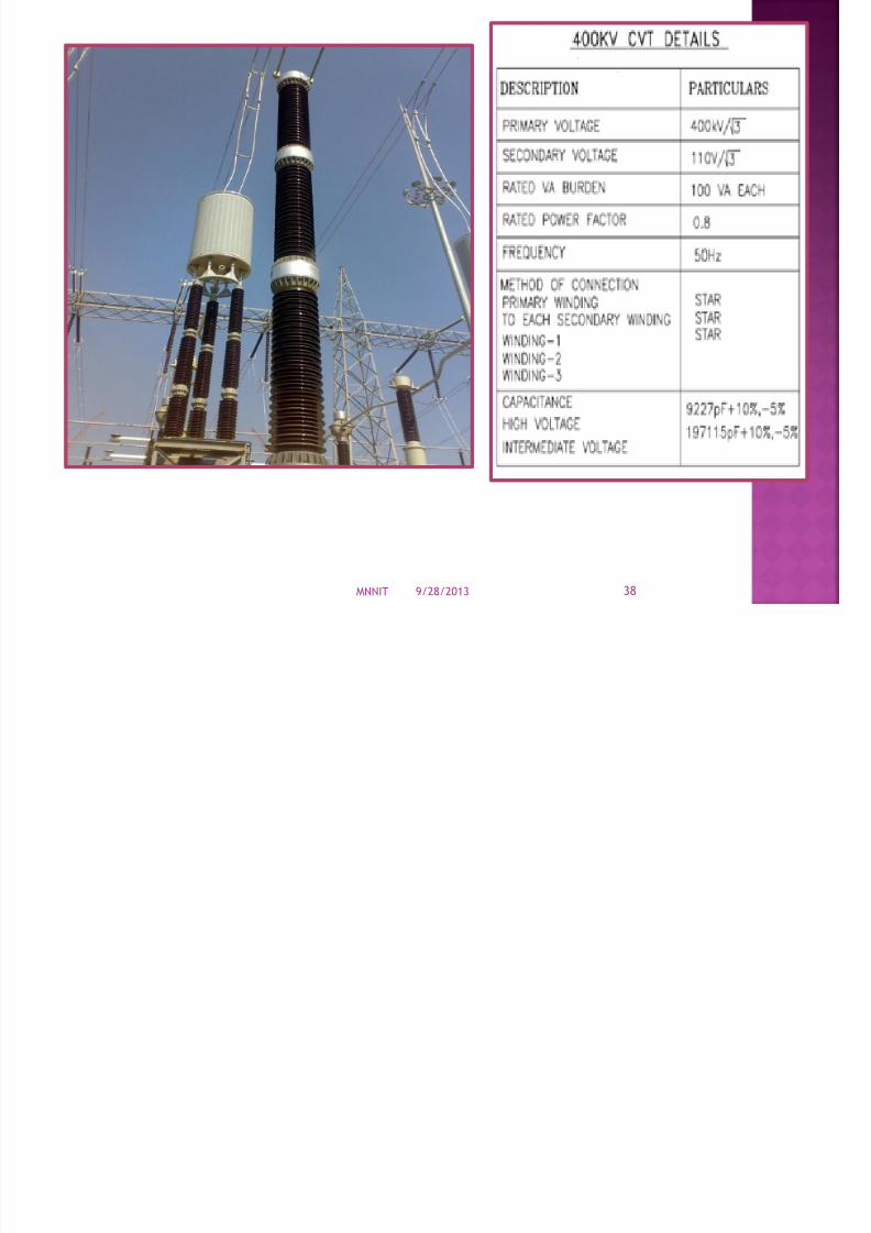
The CVT is a capacitor divider with top connected to the line (400kV)and bottom earthed.
9/28/2013MNNIT 36

7/28/2019 Thermal Power Plant Introduction
http://slidepdf.com/reader/full/thermal-power-plant-introduction 37/51
A tap of the capacitor at 22 kV is connected to a transformer inside
the tank. The transformer will have 3 secondary windings to give 110
V each.
2 cores are for protection, 1 for metering.
9/28/2013MNNIT 37
7/28/2019 Thermal Power Plant Introduction
http://slidepdf.com/reader/full/thermal-power-plant-introduction 38/51
9/28/2013MNNIT 38

7/28/2019 Thermal Power Plant Introduction
http://slidepdf.com/reader/full/thermal-power-plant-introduction 39/51
In this type of vts the voltage step down takes place by
means of electro magnetic circuit.
It is specially dedicated for line metering purposes.
9/28/2013MNNIT 39

7/28/2019 Thermal Power Plant Introduction
http://slidepdf.com/reader/full/thermal-power-plant-introduction 40/51
These are the electrical switches to completely de-energized anelectrical circuit for service or maintenance
Isolators are disconnecting switches it is used for open the circuitunder no load condition
Opened or closed only when circuit breaker is open.
Accompanied with Earth Switches to earth the residual/magnetizing currents when isolator opens.
Two types
Horizontal Upright
Pantograph Isolator
Center breakIsolator Specifications
Rated Voltage: 420 kV
Rated Current: 2500 A
9/28/2013MNNIT 40

7/28/2019 Thermal Power Plant Introduction
http://slidepdf.com/reader/full/thermal-power-plant-introduction 41/51
9/28/2013MNNIT 41

7/28/2019 Thermal Power Plant Introduction
http://slidepdf.com/reader/full/thermal-power-plant-introduction 42/51
Earth Switch is connected between the line conductor and Earth.
Normally it is open when the line is disconnected, the earth switch isclosed so as to discharge the voltage trapped on the line capacitanceto the earth.
When isolator is in open condition, earth switch is closed and viceversa. Normally the Earth switch is mounted on the frame of theisolator
9/28/2013MNNIT 42

7/28/2019 Thermal Power Plant Introduction
http://slidepdf.com/reader/full/thermal-power-plant-introduction 43/51
It is used for measurement of current as well as protectionpurposes.
Much higher values of line currents will be stepped down tosome standard low values, thus can be measured easily.
CT is always connected in series with the power line with theprimary being the line itself.
The secondary winding is having taps to have different CTratios such as 2000/1, 1000/1, 500/1.
There are 5 secondary windings.
Core I - Metering or measurement
Core II – Open Circuit, Earth fault, Back UpProtection
Core III - Main Protection(Differential Protection for
Transformer, DistanceProtection for lines)
Core IV & V – Bus Bar protection
9/28/2013MNNIT 43
CT Type Purpose Accuracy Burden

7/28/2019 Thermal Power Plant Introduction
http://slidepdf.com/reader/full/thermal-power-plant-introduction 44/51
9/28/2013MNNIT 44
CT Type Purpose Accuracy Burden
2 CORE Metering 0.2 S 5 VA
4 CORE Metering 0.2 S 5 VA
5 CORE CoreI,II,IV,V
Protection PS 20 VA
Core III Metering 0.2 S 20 VA

7/28/2019 Thermal Power Plant Introduction
http://slidepdf.com/reader/full/thermal-power-plant-introduction 45/51
key component in PLC (Power Line Carrier) systems
Used for remote control signals, voice communication, remotemetering and control between substations in the electrical T&D
network.
High voltage transmission lines are also used for transmitting
carrier signals between 30 kHz and 500 kHz Line traps prevent transmission of these high frequency signals to
unwanted directions without loss of energy at power frequency.
Line traps are series-connected
to the transmission lines.
Continuous Current Rating: 2400 A
9/28/2013MNNIT 45

7/28/2019 Thermal Power Plant Introduction
http://slidepdf.com/reader/full/thermal-power-plant-introduction 46/51
Main coil carries the rated current of the transmission line and is designed to withstand the
maximum short-circuit current. Its low self-capacitance provides a high self-resonance
frequency
Extremely reliable tuning devices This key sub-component of a line trap is mounted
inside the main coil on the central tie rod.
Protective Device The protective device is connected across the main coil and the tuning
device to prevent the line trap from being damaged by transient overvoltages9/28/2013MNNIT 46

7/28/2019 Thermal Power Plant Introduction
http://slidepdf.com/reader/full/thermal-power-plant-introduction 47/51
It is a protective device which diverts the transient over voltagesurges to earth & protect the substation equipment from lightning& switching over voltage surges.
Acts as open circuit during normal conditions and provides a shortcircuit path during lightning surges and over voltages.
The connection made in LA is, one terminal is plugged in to highvoltage terminal & other terminal is earthed.
They are generally connected in parallel with the equipment to beprotected and function to divert the surge current safely to ground.
They present high impedance at power frequency but low
impedance to surge currents. SPECIFICATIONS
Zinc Oxide, Gapless Type
Rated Voltage: 360 kV
Nominal Discharge Current: 10 kA
9/28/2013MNNIT 47

7/28/2019 Thermal Power Plant Introduction
http://slidepdf.com/reader/full/thermal-power-plant-introduction 48/51
9/28/2013MNNIT 48

7/28/2019 Thermal Power Plant Introduction
http://slidepdf.com/reader/full/thermal-power-plant-introduction 49/51
One and a half breaker scheme makes it reliable.
Almost Zero Emission Plant.
Full Utilization of Steam is ensured.
Coal Waste is proposed to be managed to make
Bricks.
9/28/2013MNNIT 49

7/28/2019 Thermal Power Plant Introduction
http://slidepdf.com/reader/full/thermal-power-plant-introduction 50/51
We have come to know what all processes are neededto generate and run the plant on a 24x7 basis.
This plant is an example in terms of working efficiency
and management of resources to all other thermalplants in our country.
The training gave us an opportunity to clear our
concepts from practical point of view with the availability
of machinery.
9/28/2013MNNIT 50

7/28/2019 Thermal Power Plant Introduction
http://slidepdf.com/reader/full/thermal-power-plant-introduction 51/51
Related Documents