Welcome message from author
This document is posted to help you gain knowledge. Please leave a comment to let me know what you think about it! Share it to your friends and learn new things together.
Transcript

THERMAL PLASMATORCHES
ANDTECHNOLOGIES
THERMAL PLASMATORCHES
AND
TECHNOLOGIESVolume 1: Plasma Torches. Basic Studies and Design
edited by
O.P. Solonenko
Institute of Theoretical and Applied Mechanics, Siberian Branch of theRussian Academy of Sciences, Novosibirsk
CAMBRIDGE INTERNATIONAL SCIENCE PUBLISHING

Published byCambridge International Science Publishing7 Meadow Walk, Great Abington, Cambridge CB1 6AZ, UKhttp://www.cisp-publishing.com
Published 2003
© Cambridge International Science Publishing
Conditions of saleAll rights reserved. No part of this publication may be reproduced ortransmitted in any form or by any means, electronic or mechanical, includingphotocopy, recording, or any information storage and retrieval system,without permission in writing from the publisher
British Library Cataloguing in Publication DataA catalogue record for this book is available from the British Library
ISBN 1 898326592

Contents
Electric Arc Generators of Thermal Plasma: Review (M.F. Zhukov) .............. 1Trends in Thermal Plasma Technology (L.F. Pfender) ...................................... 20Integrated Analysis of Induction Plasma Systems (M.I. Boulos) ...................... 42Plasma Metallurgy: Current State, Problems and Prospects (Yu.V. Tsvetkov) 62Atmosphere Plasma Spraying: Theory, Modelling, Diagnostics, Computer-
Aided Design and Some Applications (O.P. Solonenko) ............................... 80Metallic and Ceramic Materials: Present and Future (V.A. Neronov) .......... 102Extreme Technologies in Building Material Production (G.G. Volokitin, V.E. Borzykh, N.K. Skripnikova) .................................................................... 112Achievements of Plasma Tomography (V.V. Pickalov) ...................................... 123New Vortex Method of Plasma Insulation and the Ranque Effect (A. Gutsol and J.A. Bakken) .............................................................................................. 133Physical Phenomena in a Hollow Cathode and Interaction of Powder with the Vacuum Arc (V.S. Cherednichenko, A.B. Zagorskii and L.K. Pavlenko) ..
.......................................................................................................................... 150Experimental Investigation of Electric, Energetic and Optical Character- istics of the Induction Transformer-Type Discharge (I.M. Ulanov and S.N. Soldatov) .................................................................................................. 166Mathematical Modelling of Transformer Discharge (E.B. Kulumbaev and V.M. Lelevkin) .................................................................................................. 175Integrated Method of Research of Processes in Thermal Plasma Generators (O.Y. Novikov and V.F. Putko) .................................................... 191Modelling of Electric Arc Plasma (A. Zhainakov, R. Urusov and A. Valeeva) 197On the Problem of Turbulent Arc Modelling (O.I. Yas'ko) .............................. 206Energy Characteristics of Electric Arc Heaters for Tetrafluoromethane (A.N.
Timoshevskii, B.A. Pozdnyakov and V.S. Ponkratov) ................................... 224Numerical Investigation of the Characteristics of a Steady Curved Arc in
External Fields (G.A. Desyatkov, V.Ts. Gurovich and E.B. Kulumbaev) .... 231Properties of Water-Stabilized Plasma Torches (M. Hrabovsky, M. Konrad, V.
Kopecky and V. Sember) .................................................................................. 242Modeling of a D. C. Arc Plasma Torch with a Hydrogen-Argon Mixture as the Working Gas (Xi Chen, Peng Han and Lan Yu) ................................ 267The Modified Balance Method of Calculating Characteristics of Near- Anode Processes (Yu.V. Bruevich, I.P. Nazarenko and I.G. Panevin) ......... 280Application of Heat Diffusion Theory to Cold Electrode Erosion for Nonsta-
tionary Arc Spots (A. Marotta and L.I. Sharakhovsky) .............................. 291Emission Current Density and Electronic Work Function of Metal to Plasma (H.Ts. Zayatuev) ................................................................................. 310Erosion of Multi-arc Cathodes (A.N. Timoshevkii and V.S. Ponkratov) .......... 319Influence of Three-Phase Electric Arcs, Burning on Oxide Melts, on Quality of Electric Power (U.B. Ashimov, E.A. Abdrachmanov, G.D.
Manapova and T.S. Maldybaeva) ................................................................... 326Modelling of Flow Stabilization by the Swirl of a Peripheral Flow as Applied to Plasma Reactors (E.P. Volchkov, V.P. Lebedev, V.I. Terekhov and

N.E. Shishkin) .................................................................................................. 335Low-density Plasma Jets: Production and Investigation (L.I. Kuznetsov and
V.N. Yarygin) .................................................................................................... 352Effect of Arc Current Modulation on Thermal Plasma Flow in Plasma Torches
(F.A. Salyanov) ................................................................................................. 365

PREFACE
Our original intention was to publish this two-volume book at theoccasion of the 80th birthday of Prof. Mikhail F. Zhukov, Academicianof the Russian Academy of Sciences, one of the leading Russian andCIS scientists working in the area of plasma science and technol-ogy. Unfortunately, Prof Zhukov died in December 1999 and we wouldtherefore like to devote this book to the life and scientific achievementof this outstanding scientist, pioneer of thermal plasma.
He was born September 6, 1917 and graduated from the MoscowState University (in mechanics) in 1941. He started working as anengineer in the Zhukovsky Central Aerodynamics Institute. In 1946-1959, he was the head of the department in the Central Institute ofAirplane Engines. Since 1960 until his death, Mikhail F. Zhukov workedin the Siberian Branch of the Russian Academy of Sciences. Zhukov’sfundamental investigations in the fields of gas dynamics and elec-tric arc thermal plasma are well known in Russia and abroad. Thescope of his scientific interests was very wide: supersonic compressors,
Mikhail F. Zhukov

new types of wind tunnels, near-electrode processes, electrode erosion,heat transfer, arcing stability, new plasma technologies, etc.
Zhukov’s scientific school on plasma dynamics is known to bothRussian and foreign investigators. M.F. Zhukov was a pioneer ofexperimental investigations of thermal plasma generators. He and hisdisciples were the first involved in the study of some fundamentalphysical processes in electric arc plasma. He developed a universalsystem of similarity criteria and estimated the significance of thesevalues under specific arcing conditions. He elaborated the arcing theoryin a laminar flow. His engineering methods for designing the elec-tric and thermal characteristics of electric arc plasma torches are usedwidely in the development of laboratory and industrial apparatuses.
Zhukov’s team have carried out numerous investigations concerningnear-electrode processes, heat transfer through the arc spot, ‘split-ting’ of the closing radial part of the arc in linear scheme plasmatorches. They have also investigated the problem of stability of multi-arc system operation without a ballast resistance in the electric circuit.These studies allowed the development of highly effective linear plasmagenerators and high-current cathode units with a long operation timein different gas media. Twenty years ago, he put forward a hypothesisabout the recirculation of cathode material’s atoms close to the surface.This was discovered later in experiments. It was a specific case, butit opened the way to solving the problem. A new class of high-resource cathodes has been developed, including the non-erosion cathodeworking in a carbon-containing medium.
Powerful high-enthalpy arc plasma generators with interelectrodeinserts were developed under the supervision of M.F. Zhukov. Theyare widely used in plasma chemical technologies. There were sig-nificant achievements in the production of ultrafine powder ofrefractory compounds, synthesized in plasma chemical reactors. Thesepowders are also used in metallurgy for the improvement of the physicaland mechanical properties of ferrous and nonferrous metals.
M. Zhukov’s intuition and his vision of future conditioned theappearance in the 1980s of a new scientific and technological direction– plasma dynamics of dispersed systems. His achievements determinedthe progress in plasma-jet spraying with powder coatings and com-positions. His team has made a great contribution to the investigationand practical realization of plasma (no fuel oil) igniters in the grid-coal power stations.
The popularization of science achievements and their applicationsreceived a lot of attention from M. Zhukov. He wrote and spoke aboutdifferent subjects: plasma for powder spraying, metal cutting and

processing, waste treatment, recirculation of toxic waste to a serviceableproduct, etc. He often spoke at lectures to engineering public, sci-entific-practical workshops, radio and TV. Thus, he promoted the wholerange of possible practical applications of electric-arc thermal plasmain new technologies.
M.F. Zhukov is the author of many books and articles. With hisparticipation and under his editing, the whole series of famous bookswith plasma torch construction has been published. The publicationof 20-volume series ‘Low-Temperature Plasma’ will soon be com-pleted. Many of these books have became essential reading for re-searchers and specialists in the field of thermal and low-tempera-ture plasma. These editions have became a theoretical tool for thedesign and manufacturing of high-efficiency equipment for new plasmatechnologies.
Mikhail Zhukov was a man of many interests. In addition to carryingout extensive investigations, he was an organizer and participant ofconferences and workshops on gas-discharge plasma for almost fortyyears.
From 1975 until 1980, M.F. Zhukov was the Chief Scientific Secretaryof the Presidium of the Siberian Branch of the USSR Academy ofSciences. He was the Editor-in chief of the journal ‘Communicationsof SB AS USSR’ for 15 years, and a member of the Editorial boardof ‘Contributions to Plasma Physics’. Mikhail F. Zhukov was the Acad-emician of the International Energy Academy, a Honorable Academicianof the Engineering Sciences Academy.
M.F. Zhukov was the Head of the Plasma Dynamics Departmentof the Institute of Theoretical and Applied Mechanics of the Sibe-rian Division of the Russian Academy of Sciences. He was absorbedwith new creative plans and aspirations.
This book is published as a result of international scientific andtechnical discussions and collaboration which took place during thepreparation and running of 3rd International Workshop on ThermalPlasma Torches and Technologies (TPPT’97) (25-29 August, 1997,Novosibirsk, Akademgorodok, Russia). The organisation of this Workshopand preparation of this collection were sponsored by the Siberian Branchof Russian Academy of Sciences, Samsung Heavy Industries Co. Ltd.,Daeduk R&D Center (Taejeon, Korea), Gusinoozyerskaya GRES(Gusinoozyersk, Russia), Novosibirsk Plant ‘Khimkontsentrat’ (Nov-osibirsk, Russia) and Production-Promotion Company ‘Mercury-II’Ltd. (Tomsk, Russia).
Leading scientists presenting the scientific school of Prof. MikhaelF. Zhukov and other leading scientists in plasma research and de-

velopment from Russia, CIS, USA, Canada, France, Japan, CzechRepublic, China, Brazil, Norway, Yugoslavia and Korea have con-tributed this book.
Prof. Oleg P. Solonenko,Editor

Contents
Electric Arc Generators of Thermal Plasma: Review (M.F. Zhukov) .............. 1
Trends in Thermal Plasma Technology (L.F. Pfender) ...................................... 20
Integrated Analysis of Induction Plasma Systems (M.I. Boulos) ...................... 42
Plasma Metallurgy: Current State, Problems and Prospects (Yu.V. Tsvetkov) 62
Atmosphere Plasma Spraying: Theory, Modelling, Diagnostics, Computer-Aided Design and Some Applications (O.P. Solonenko) ............................... 80
Metallic and Ceramic Materials: Present and Future (V.A. Neronov) .......... 102
Extreme Technologies in Building Material Production (G.G. Volokitin, V.E. Borzykh, N.K. Skripnikova) .................................................................... 112
Achievements of Plasma Tomography (V.V. Pickalov) ...................................... 123
New Vortex Method of Plasma Insulation and the Ranque Effect (A. Gutsol and J.A. Bakken) .............................................................................................. 133
Physical Phenomena in a Hollow Cathode and Interaction of Powder with the Vacuum Arc (V.S. Cherednichenko, A.B. Zagorskii and L.K. Pavlenko) ..
.......................................................................................................................... 150
Experimental Investigation of Electric, Energetic and Optical Character- istics of the Induction Transformer-Type Discharge (I.M. Ulanov and S.N. Soldatov) .................................................................................................. 166
Mathematical Modelling of Transformer Discharge (E.B. Kulumbaev and V.M. Lelevkin) .................................................................................................. 175
Integrated Method of Research of Processes in Thermal Plasma Generators (O.Y. Novikov and V.F. Putko) .................................................... 191
Modelling of Electric Arc Plasma (A. Zhainakov, R. Urusov and A. Valeeva) 197
On the Problem of Turbulent Arc Modelling (O.I. Yas'ko) .............................. 206
Energy Characteristics of Electric Arc Heaters for Tetrafluoromethane (A.N.Timoshevskii, B.A. Pozdnyakov and V.S. Ponkratov) ................................... 224
Numerical Investigation of the Characteristics of a Steady Curved Arc inExternal Fields (G.A. Desyatkov, V.Ts. Gurovich and E.B. Kulumbaev) .... 231
Properties of Water-Stabilized Plasma Torches (M. Hrabovsky, M. Konrad, V.Kopecky and V. Sember) .................................................................................. 242
Modeling of a D. C. Arc Plasma Torch with a Hydrogen-Argon Mixture as the Working Gas (Xi Chen, Peng Han and Lan Yu) ................................ 267
The Modified Balance Method of Calculating Characteristics of Near- Anode Processes (Yu.V. Bruevich, I.P. Nazarenko and I.G. Panevin) ......... 280
Application of Heat Diffusion Theory to Cold Electrode Erosion for Nonsta-tionary Arc Spots (A. Marotta and L.I. Sharakhovsky) .............................. 291
Emission Current Density and Electronic Work Function of Metal to Plasma (H.Ts. Zayatuev) ................................................................................. 310
Erosion of Multi-arc Cathodes (A.N. Timoshevkii and V.S. Ponkratov) .......... 319
Influence of Three-Phase Electric Arcs, Burning on Oxide Melts, on Quality of Electric Power (U.B. Ashimov, E.A. Abdrachmanov, G.D.
Manapova and T.S. Maldybaeva) ................................................................... 326
Modelling of Flow Stabilization by the Swirl of a Peripheral Flow as Applied to Plasma Reactors (E.P. Volchkov, V.P. Lebedev, V.I. Terekhov and
N.E. Shishkin) .................................................................................................. 335
Low-density Plasma Jets: Production and Investigation (L.I. Kuznetsov andV.N. Yarygin) .................................................................................................... 352
Effect of Arc Current Modulation on Thermal Plasma Flow in Plasma Torches(F.A. Salyanov) ................................................................................................. 365
1
Electric Arc Generators of Thermal Plasma: Review
M.F. ZhukovInstitute of Theoretical and Applied Mechanics, Siberian Branch, Russian Academyof Sciences, Novosibirsk, Russia
The main electrical and physical processes in a discharge chamber ofa linear plasma torch are reviewed. The classification of linear plasmatorches is proposed. The diagrams of the plasma torches for technologicalprocesses and plasma chemical reactors as well as their problems arediscussed.
!!"#$!$$$ "
$"" %&!$ "$ '(
The dynamics of electric arc plasma includes a complex physicalphenomenon, occurring in the discharge chamber of the plasma torch,which can be regarded as both thermal and an electric and physical device.The electric arc is influenced by different factors: the gas flow, innerand outer magnetic fields, construction elements of the chamber whichconfine the arc, the elements being often under electric voltage, differingfrom that of the arc. Thus, there is a strong need for deep understandingof a wide spectrum of the processes taking place in the discharge chamberin order to develop highly effective plasma torches.
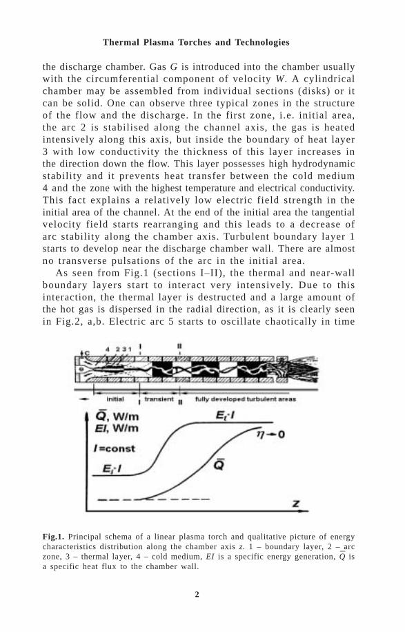
1.1. Dynamics of the gas flow in the cylidrical channel andstructure of the arc column [2]Figure 1 presents the principal scheme of a linear plasma torch witha long discharge chamber and the qualitative distribution picture of itsenergetic characteristics along the z axis, i.e. the specific energy generationof arc EI and the full specific heat flux per unit length of the chamberwall Q .
The arc burns between two electrodes, placed at the ends of
2
Thermal Plasma Torches and Technologies
the discharge chamber. Gas G is introduced into the chamber usuallywith the circumferential component of velocity W. A cylindricalchamber may be assembled from individual sections (disks) or itcan be solid. One can observe three typical zones in the structureof the flow and the discharge. In the first zone, i.e. initial area,the arc 2 is stabilised along the channel axis, the gas is heatedintensively along this axis, but inside the boundary of heat layer3 with low conductivity the thickness of this layer increases inthe direction down the flow. This layer possesses high hydrodynamicstability and it prevents heat transfer between the cold medium4 and the zone with the highest temperature and electrical conductivity.This fact explains a relatively low electric field strength in theinitial area of the channel. At the end of the initial area the tangentialvelocity field starts rearranging and this leads to a decrease ofarc stability along the chamber axis. Turbulent boundary layer 1starts to develop near the discharge chamber wall. There are almostno transverse pulsations of the arc in the initial area.
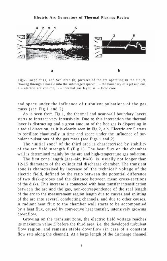
As seen from Fig.1 (sections I–II), the thermal and near-wallboundary layers start to interact very intensively. Due to thisinteraction, the thermal layer is destructed and a large amount ofthe hot gas is dispersed in the radial direction, as it is clearly seenin Fig.2, a,b. Electric arc 5 starts to oscillate chaotically in time
Fig.1. Principal schema of a linear plasma torch and qualitative picture of energycharacteristics distribution along the chamber axis z. 1 – boundary layer, 2 – arczone, 3 – thermal layer, 4 – cold medium, EI is a specific energy generation, Q isa specific heat flux to the chamber wall.
–
3
Electric Arc Generators of Thermal Plasma: Review
and space under the influence of turbulent pulsations of the gasmass (see Fig.1 and 2).
As is seen from Fig.1, the thermal and near-wall boundary layersstarts to interact very intensively. Due to this interaction the thermallayer is distructing and a great amount of the hot gas is dispersing ina radial direction, as it is clearly seen in Fig.2, a,b. Electric arc 5 startsto oscillate chaotically in time and space under the influence of tur-bulent pulsations of the gas mass (see Figs.1 and 2).
The ‘initial zone’ of the third area is characterised by stabilityof the arc field strength E (Fig.1). The heat flux on the chamberwall is determined mainly by the arc and high-temperature gas radiation.
The first zone length (gas–air, W≠0) is usually not longer than12-15 diameters of the cylindrical discharge chamber. The transientzone is characterised by increase of ‘the technical’ voltage of theelectric field, defined by the ratio between the potential differenceof two disk–probes and the distance between mean cross-sectionsof the disks. This increase is connected with heat transfer intensificationbetween the arc and the gas, non-correspondence of the real lengthof the arc to the measurement region length due to curves and splittingof the arc into several conducting channels, and due to other causes.A radiant heat flux to the chamber wall starts to be accompaniedby a heat flux, caused by convective heat transfer, intensively growingdownflow.
Growing on the transient zone, the electric field voltage reachesits maximum value E before the third area, i.e. the developed turbulentflow region, and remains stable downflow (in case of a constantflow rate along the channel). At a large length of the discharge channel
a b
Fig.2. Toeppler (a) and Schlieren (b) pictures of the arc operating in the air jet,flowing through a nozzle into the submerged space: 1 – the boundary of a jet nucleus,2 – electric arc column, 3 – thermal gas layer, 4 – flow core.

4
Thermal Plasma Torches and Technologies
with the developed turbulent flow and at the lack of measures aimedat decreasing the heat flux on the wall, the heat flux, starting insome channel section, approaches the value of specific energy releasedby the arc, i.e. local heat efficiency approaches zero.
1.2. Shunting [1]Shunting, i.e. electric breakdown 2 between arc 1 and plasma torchchamber wall (Fig.3a), is the most typical electric process whenan arc burns in a cylindrical chamber.
Let us investigate the qualitative picture of arc shunting in an exitelectrode of a single-chamber plasma torch. Let us assume that at timemoment t
1 the arc is occupying the position ABC. Under the influence
of hydrodynamic and electrodynamic forces, the radial section of thearc AB drifts into the flow direction, and as a result of this the arc lengthand voltage increase and they are connected together by the ratio
∫+∆=)(
0
)(tl
e dllEVU ,
where U is the sum of near-electrode potential drops, E(l) is the electricfield strength, l(t) is the arc length at time t.
Fig.3. (a) - The scheme of arc shunting in dc plasma torch with a cylindrical exitelectrode: 1 - the arc, 2 - large-scale shunting, 3 and 4 - small-scale shunting;(b) - qualitative picture of a break-down generation between the arc and the plasmatorch electrode.
5
Electric Arc Generators of Thermal Plasma: Review
In electric arc generators ∆V E l dle
l t
<< ∫ ( )( )
0
. To explain the shunting
process let us investigate the simplest case, when E(l)=const.We also assume that the exit electrode potential is equal to zero,
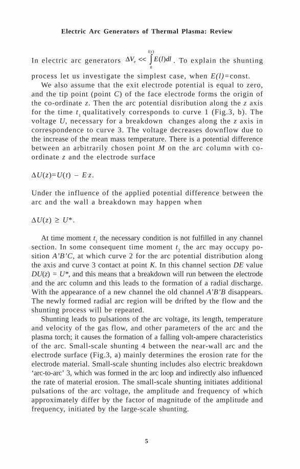
and the tip point (point C) of the face electrode forms the origin ofthe co-ordinate z. Then the arc potential disribution along the z axisfor the time t
1 qualitatively corresponds to curve 1 (Fig.3, b). The
voltage U, necessary for a breakdown changes along the z axis incorrespondence to curve 3. The voltage decreases downflow due tothe increase of the mean mass temperature. There is a potential differencebetween an arbitrarily chosen point M on the arc column with co-ordinate z and the electrode surface
∆U(z)=U(t) – E.z .
Under the influence of the applied potential difference between thearc and the wall a breakdown may happen when
∆U(z) ≥ U*.
At time moment t1 the necessary condition is not fulfilled in any channel
section. In some consequent time moment t2 the arc may occupy po-
sition A’B’C, at which curve 2 for the arc potential distribution alongthe axis and curve 3 contact at point K. In this channel section DE valueDU(z) = U*, and this means that a breakdown will run between the electrodeand the arc column and this leads to the formation of a radial discharge.With the appearance of a new channel the old channel A’B’B disappears.The newly formed radial arc region will be drifted by the flow and theshunting process will be repeated.
Shunting leads to pulsations of the arc voltage, its length, temperatureand velocity of the gas flow, and other parameters of the arc and theplasma torch; it causes the formation of a falling volt-ampere characteristicsof the arc. Small-scale shunting 4 between the near-wall arc and theelectrode surface (Fig.3, a) mainly determines the erosion rate for theelectrode material. Small-scale shunting includes also electric breakdown‘arc-to-arc’ 3, which was formed in the arc loop and indirectly also influencedthe rate of material erosion. The small-scale shunting initiates additionalpulsations of the arc voltage, the amplitude and frequency of whichapproximately differ by the factor of magnitude of the amplitude andfrequency, initiated by the large-scale shunting.
6
Thermal Plasma Torches and Technologies
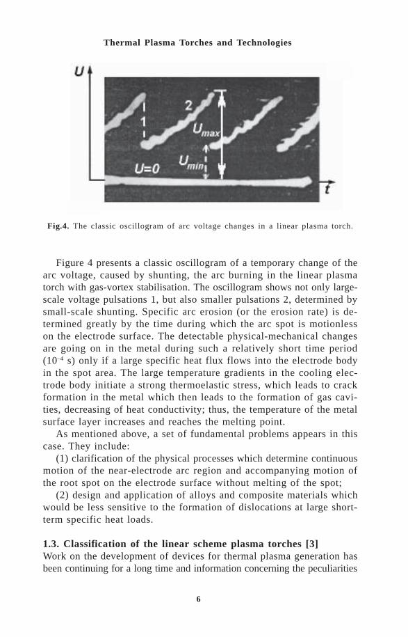
Figure 4 presents a classic oscillogram of a temporary change of thearc voltage, caused by shunting, the arc burning in the linear plasmatorch with gas-vortex stabilisation. The oscillogram shows not only large-scale voltage pulsations 1, but also smaller pulsations 2, determined bysmall-scale shunting. Specific arc erosion (or the erosion rate) is de-termined greatly by the time during which the arc spot is motionlesson the electrode surface. The detectable physical-mechanical changesare going on in the metal during such a relatively short time period(10–4 s) only if a large specific heat flux flows into the electrode bodyin the spot area. The large temperature gradients in the cooling elec-trode body initiate a strong thermoelastic stress, which leads to crackformation in the metal which then leads to the formation of gas cavi-ties, decreasing of heat conductivity; thus, the temperature of the metalsurface layer increases and reaches the melting point.
As mentioned above, a set of fundamental problems appears in thiscase. They include:
(1) clarification of the physical processes which determine continuousmotion of the near-electrode arc region and accompanying motion ofthe root spot on the electrode surface without melting of the spot;
(2) design and application of alloys and composite materials whichwould be less sensitive to the formation of dislocations at large short-term specific heat loads.
1.3. Classification of the linear scheme plasma torches [3]Work on the development of devices for thermal plasma generation hasbeen continuing for a long time and information concerning the peculiarities
Fig.4. The classic oscillogram of arc voltage changes in a linear plasma torch.

7
Electric Arc Generators of Thermal Plasma: Review
of their work has been accumulated; from time to time, a more detailedclassification is needed. This helps to estimate objectively the existingresults and outline new ways of developing more effective systems appliedto new technologies.
Let us analyse the classification of only linear plasma torches, whichrepresent a wide range of plasma generators regading the consumed power,variations of applied working gases and pressure ranges.
Knowledge of fundamental physical processes, taking place in thedischarge chamber of a plasma torch, helps to suggest a simple clas-sification and to reduce multiple constructive solutions to three prin-cipal classes.
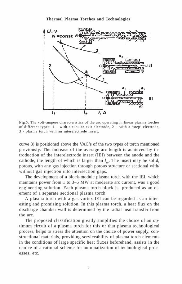
The first class consists of the plasma torch with a tubular exit electrodeand self-aligning arc length. This type of torch is used widely in theindustry and scientific research work. The volt–ampere characteristics(VAC) of these plasma torches are of the drooping nature (Fig.5, curve1). The average arc length l is a function of current value, chamberdiameter, gas flow rate, pressure and it depends on the working gas andon the polarity of the exit electrode. The large-scale shunting, takingplace in the transient zone of the discharge channel, forms the mechanismfor arc length changes.
The second class of the plasma torches is characterised by the factthat the average arc length l is constant in a relatively wide range ofcurrent changes (I
a < I < I
1), while the other parameters, mentioned above,
are constant, and this length is always less than that for the self-aligningarc I
a < I
sa. The VAC is U-shaped (Fig.5, curve 2). Without taking special
measures, the value of U is limited by the contact point of two VAClines (point a). At I > I
a, curve 1 merges with curve 2 into a single
VAC of the arc, because arc shunting in this case takes place in a channelwith diameter d
2.
There are several technical solutions, providing the constant aver-age arc length. One is a peculiarity of a broken gas flow behind a step,formed by the step construction of the exit electrode, that consists oftwo cylinders with different diameters, the diameter of the exit part ofthe electrode d
3, being larger than d
2. This forms the basis of one of
technical solutions, which draws the greatest attention of the engineers.We should mention that the VAC of the arc I is positioned below theVAC of the arc with self-aligning length. These plasma torches are workingin a stable manner without additional resistance in the circuit on therising branch of the arc VAC.
Recently, special attention has been paid to the third type of linearplasma torches, in which the average arc length in non-changeable, butlonger than that of the self-aligning arc [4]. The VAC of this arc (Fig.5,
8
Thermal Plasma Torches and Technologies
curve 3) is positioned above the VAC’s of the two types of torch mentionedpreviously. The increase of the average arc length is achieved by in-troduction of the interelectrode insert (IEI) between the anode and thecathode, the length of which is larger than l
sa. The insert may be solid,
porous, with any gas injection through porous structure or sectional with/without gas injection into intersection gaps.
The development of a block-module plasma torch with the IEI, whichmaintains power from 1 to 3–5 MW at moderate arc current, was a goodengineering solution. Each plasma torch block is produced as an el-ement of a separate sectional plasma torch.
A plasma torch with a gas-vortex IEI can be regarded as an inter-esting and promising solution. In this plasma torch, a heat flux on thedischarge chamber wall is determined by the radial heat transfer fromthe arc.
The proposed classification greatly simplifies the choice of an op-timum circuit of a plasma torch for this or that plasma technologicalprocess, helps to stress the attention on the choice of power supply, con-structional materials, providing serviceability of plasma torch elementsin the conditions of large specific heat fluxes beforehand, assists in thechoice of a rational scheme for automatization of technological proc-esses, etc.
Fig.5. The volt–ampere characteristics of the arc operating in linear plasma torchesof different types: 1 – with a tubular exit electrode, 2 – with a ‘step’ electrode,3 - plasma torch with an interelectrode insert.

9
Electric Arc Generators of Thermal Plasma: Review
) *+, !$ " '-(
The rapid growth of the plasma torch technologies requires new, morestringent demands for plasma torch parameters such as life-time, operationakstability of the electric arc, the possibility to use a wide range of plasma-forming (working) gases, relatively simple construct-ion of generatorsand launching systems for electric arc initiation. There are technologicalprocesses in which it is more expedient and energetically profitable totreat surfaces directly by the electric arc. In this case, the intensity ofheat fluxes on treated surfaces, depending on conditions of arc interactionwith the surface, varies from 1 × 10⁷ to 25 × 107 W/m2.
Among many types of electric arc plasma torches one should men-tion two-jet ones. In these torches, the large part of the arc burns inthe open space. In the general case, the operating regime, including thearc VAC, is determined not only by current values, gas flow rate andits properties, but also by electrode disposition.
Some design peculiarities form the basis of this type of two-jet plasmatorches. They are connected with the necessity to exclude tungsten asthe cathode material, which limits ranges of working gases.
Figure 6 presents the scheme of an experimental set-up with a two-jet plasma torch. Two identical blocks, i.e. the cathode and the anodeblocks, form the constructional basis of this plasma torch. Each of themconsists of a cylindrical copper electrode, a diaphragm, electrically isolatedfrom the electrode, and two vortex chambers for gas injection.
The arc volt–ampere characteristics (Fig.7a,b) are slightly falling ina wide range of current changes for all studied types of nozzles withdifferent diameters d
2 and distances a between nozzles. The existence
Fig.6. A general scheme of an experimental set-up with a two-jet plasma torch anda power supply system.

10
Thermal Plasma Torches and Technologies
of multiple independent parameters, which influence the arc strength (I,G, d
2, internozzle distance a and the angle between electrode axes), simplifies
the choice of a power supply system and optimisation of electric char-acteristics of the plasma torch. For the case in which a = 90o (Fig.7,b), arc voltage U is calculated using formula:
U =2 × 10³ [I2/(G1+G
2)d
2]0.20[(G
1+G
2)/d
2]0.25(Pd
2)0.35×
× (2+√2a/l1)(G
1+G
2)/d.
Here l1 is the electrode length. Due to the fact that more than 2/3 of
the arc length is situated outside the cathode or anode block, the heatefficiency of the blocks is sufficiently high (~0.9).
Fig.7. Volt–ampere characteristics of the arc: a – d1 = 30 mm, d
2 = 25 mm, a = 60
mm, ∑G = 12 g/s; b – d1 = 70 mm, d
2 = 25 mm, a = 110 mm, ∑G = 40 g/s.
a
c
b
11
Electric Arc Generators of Thermal Plasma: Review
Industrial tests of this plasma torch (lasting more than 60 hours) showthat at the axis scanning of arc spots with frequency of 3 times per minutethe specific erosion of the electrodes turns to be different. For the anode,it is an order of magnitude less than that for the cathode, and is equalto 6×10–11 kg/C at current I = 200 A. Accounting for the possibility ofchanging the polarity of the electrodes, one may guarantee the life-timefor continuous work of a plasma torch as not less than 400 hours.
The above scheme of a two-jet plasma torch shows the high reliabilityof its operation, simple arc ignition, and capacity control.
-"$& #!!" % ')(
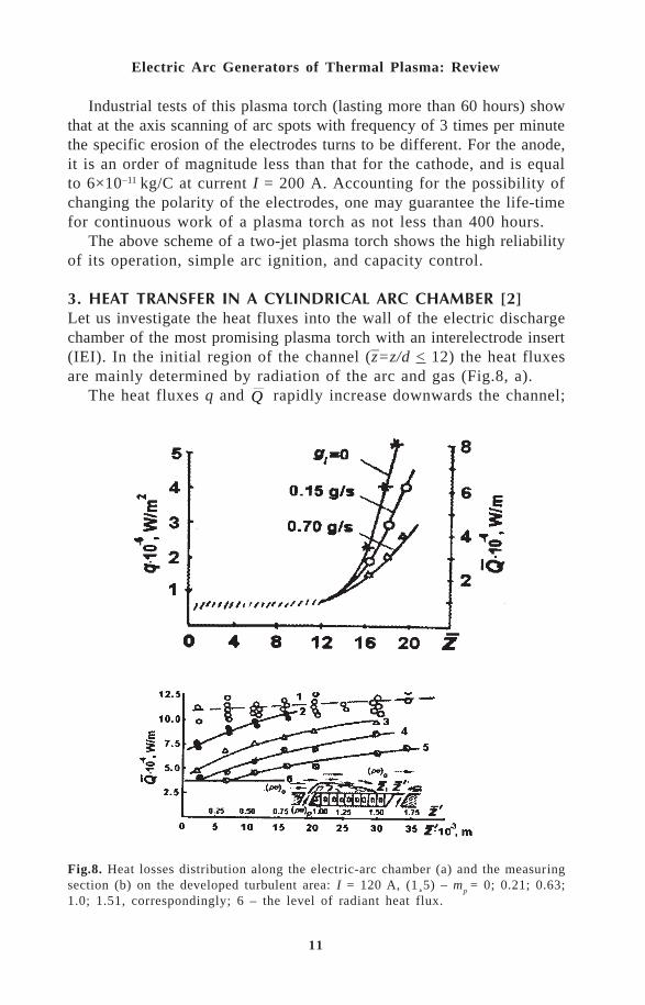
Let us investigate the heat fluxes into the wall of the electric dischargechamber of the most promising plasma torch with an interelectrode insert(IEI). In the initial region of the channel (z=z/d < 12) the heat fluxesare mainly determined by radiation of the arc and gas (Fig.8, a).
The heat fluxes q and Q rapidly increase downwards the channel;
Fig.8. Heat losses distribution along the electric-arc chamber (a) and the measuringsection (b) on the developed turbulent area: I = 120 A, (1¸5) – m
p = 0; 0.21; 0.63;
1.0; 1.51, correspondingly; 6 – the level of radiant heat flux.
–
12
Thermal Plasma Torches and Technologies
one can see the influence of an intersection gas gf injection on this
parameter. The increase of the heat flux on the wall is connected withthe growth of mean-mass gas temperature and the increase of intensityof the convective heat exchange between the gas and the wall. Figure8, b shows the heat flux distribution Q on the wall of the measuredsection, maintained in the channel in the developed turbulent region,at the different values of shielding gas injection m
p=(ρu)
p/(ρu)
o through
a slot. Without injection of a shielding gas (mp= 0), the changed heat
flux on the wall coincides with the one calculated for turbulent heatexchange (shaded line I). Injection of even a small amount of shieldinggas decreases heat fluxes (curves 2–5).
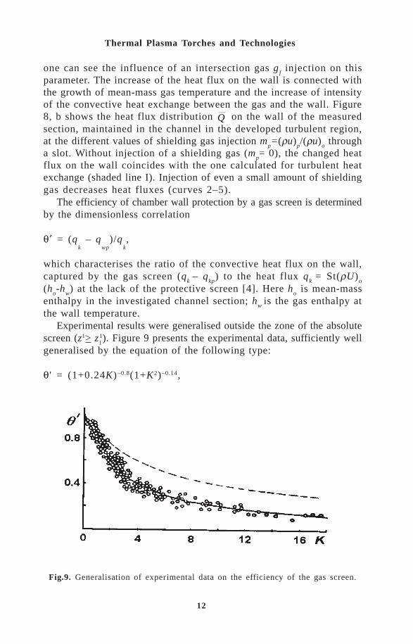
The efficiency of chamber wall protection by a gas screen is determinedby the dimensionless correlation
θ′ = (qk – q
wp)/q
k,
which characterises the ratio of the convective heat flux on the wall,captured by the gas screen (q
k – q
kp) to the heat flux q
k = St(ρU)
o
(ho-h
w) at the lack of the protective screen [4]. Here h
o is mean-mass
enthalpy in the investigated channel section; hw
is the gas enthalpy atthe wall temperature.
Experimental results were generalised outside the zone of the absolutescreen (z1> z
11). Figure 9 presents the experimental data, sufficiently well
generalised by the equation of the following type:
θ ' = (1+0.24K)–0.8(1+K2)–0.14,
Fig.9. Generalisation of experimental data on the efficiency of the gas screen.

13
Electric Arc Generators of Thermal Plasma: Review
where K= (z1–z11)Re
s–0.25/m
pS; Re
s= (ρu)
sS/µ
o. Here µ
o (measured in
Ns/m2) is the gas viscosity at the mean-mass temperature of the flow,parameter m
p was varied from 0.2 to 1.5; the slot width was changed
from 1.3× 10⁻³ to 4.2×10⁻³ m. The mean square deviation curve (continuousline) does not exceed 2%.
The first factor in the formula θ = f(K) determines the efficiencyof the gas screen on the plate [4] at the gas injection in relation to theplate, situated at angle γ = 0. The shaded line in Fig.9 demonstratesthis dependence.
. !$ "$+$
4.1. Multijet reactor [1,5,6]The use of plasma torches in chemical industry and metallurgy, inhydrodynamic investigations and for other purposes reveals some unsolvedproblems. They are closely connected with the task to create powerfuland economic electric arc reactors with long life-time, which meet thedemands, such as the uniform velocity and temperature fields along thesection. Although the power of a single plasma torch exceeds many thousandskW, it is usually released in a short period of time when using high currents,which greatly complicates the possibility of increasing the electrode durabilityand, consequently, the service life.
It is possible to solve the problem of extending the life-time by thedevelopment of a multijet reactor with a common flow mixing cham-ber, in which one portion of the working gas travels through plasmatorches and the other portion, in the case of necessity, goes directly tothe reactor. Such kinematic scheme of gas supply will simplify the controlover all parameteres, including the increase of capacity due to the in-crease of the number of plasma torches.
A three-jet reactor (Fig.10) with a total capacity of 300 kW, innerdiameter D = 0.115 m and length L = 0.23 and 0.46 m was investi-gated. Cold air was injected through the base of the cylindrical chamber.The reactor walls were cooled by water. The pressure in the reactor wasassumed to be atmospheric.
The temperature fields, shown in Fig.11, are a good illustration ofthe mixing efficiency of cold and hot gases. The optimum chamber lengthis evidently equal to L = L/D = 2.
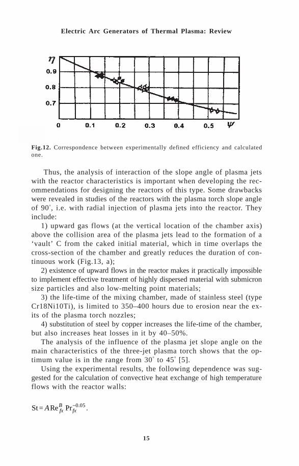
In addition to the parameter of mixing efficiency, we should mentionanother important characteristic, i.e. heat efficiency, determined bythe value of heat losses through the wall. The experiment shows thatheat efficiency is determined with satisfactory accuracy by theapproximation equation

14
Thermal Plasma Torches and Technologies
h h h= - = -( ) / Re. .1 228 0 5 0 8L .
The agreement between the calculations, using this formula, and theexperiment is shown in Fig.12, where ψ is the right side of this formula.
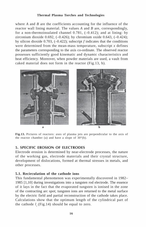
4.2. Design features of multijet reactors for producing ultrafinepowders [5]In the group of the reactors described in [7], the multijet straightreactors [8,9], in which the plasma torches are maintained at differentangles of their axes to the reactor axis, i.e. from 15 to 90 (Fig.13),have the widest technological possibilities.
Fig.10. A three-jet reactor: 1 – AC plasma torch; 2 – mixing chamber; 3 – inputof cold gas.
Fig.11. Gas temperature field at the exit of the reactor: L = 2, G2 = 30 g/s; 1 -
G1
= 60 g/s, T2/T
1 = 9.3; 2 – G
1 = 60 g/s, T
2/T
1 = 11.3; 3 – G
1 = 3 g/s, T
2/T
1 = 10.5.
15
Electric Arc Generators of Thermal Plasma: Review
Thus, the analysis of interaction of the slope angle of plasma jetswith the reactor characteristics is important when developing the rec-ommendations for designing the reactors of this type. Some drawbackswere revealed in studies of the reactors with the plasma torch slope angleof 90°, i.e. with radial injection of plasma jets into the reactor. Theyinclude:
1) upward gas flows (at the vertical location of the chamber axis)above the collision area of the plasma jets lead to the formation of a‘vault’ C from the caked initial material, which in time overlaps thecross-section of the chamber and greatly reduces the duration of con-tinuous work (Fig.13, a);
2) existence of upward flows in the reactor makes it practically impossibleto implement effective treatment of highly dispersed material with submicronsize particles and also low-melting point materials;
3) the life-time of the mixing chamber, made of stainless steel (typeCr18Ni10Ti), is limited to 350–400 hours due to erosion near the ex-its of the plasma torch nozzles;
4) substitution of steel by copper increases the life-time of the chamber,but also increases heat losses in it by 40–50%.
The analysis of the influence of the plasma jet slope angle on themain characteristics of the three-jet plasma torch shows that the op-timum value is in the range from 30° to 45° [5].
Using the experimental results, the following dependence was sug-gested for the calculation of convective heat exchange of high temperatureflows with the reactor walls:
St = A fxB
fxRe Pr .-0 05 .
Fig.12. Correspondence between experimentally defined efficiency and calculatedone.
16
Thermal Plasma Torches and Technologies
/ $& $& !$
Electrode erosion is determined by near-electrode processes, the natureof the working gas, electrode materials and their crystal structure,development of dislocations, formed at thermal stresses in metals, andother processes.
5.1. Recirculation of the cathode ionsThis fundamental phenomenon was experimentally discovered in 1982–1985 [1,10] during investigations into a tungsten rod electrode. The essenceof it lays in the fact that the evaporated tungsten is ionised in the zoneof the contracting arc spot; tungsten ions are returned to the metal surfaceby the electric field and partial reconstruction of the cathode takes place.Calculations show that the optimum length of the cylindrical part ofthe cathode l
c (Fig.14) should be equal to zero.
where A and B are the coefficients accounting for the influence of thereactor wall lining material. The values A and B are, correspondingly,for a non-thermoinsulated channel 0.781, (–0.412); and at lining: byzirconium dioxide 0.692, (–0.426); by chromium oxide 0.643, (–0.424);by silicon dioxide 0.703, (–0.422); subscript f indicates that the conditionswere determined from the mean-mass temperature, subscript x definesthe parameters corresponding to the axis co-ordinate. The observed reactorpossesses sufficiently good kinematic and dynamic characteristics andheat efficiency. Moreover, when powder materials are used, a vault fromcaked material does not form in the reactor (Fig.13, b).
a b
Fig.13. Pictures of reactors: axes of plasma jets are perpendicular to the axis ofthe reactor chamber (a) and have a slope of 30°(b).

17
Electric Arc Generators of Thermal Plasma: Review
This principle forms a basis for design and effective work of highlyeffective cathode blocks with tungsten rods with zero projection [1,10-12]. They have very small values of specific erosion G , close to1×10–13 kg/C at the atmospheric pressure in inert gase in respect to tungsten(argon, nitrogen, hydrogen) and at the current value up to 1 kA (Fig.14).The scatter of experimental data (shaded area) is wide due to many causes.The main of them are: non-qualitative stuffing of tungsten into the cooledcopper holder and, as a consequence, poor thermal contact between copperand tungsten; non-satisfactory water cooling of the cathode block, pulsationsof an arc spot along the surface of the tungsten electrode due to badarrangement of gas injection into the vortex chamber, non-coaxiality ofthe tungsten rod and a gas vortex.
The same Fig.14 shows the experimental values of the specific erosionof tungsten cylindrical rods at l
c > 0 [12]. Curve 1 characterises de-
pendence G = f (I) for cases when several tungsten rods are pressedinto the body of a copper pipe, as it is shown in Fig.14, and the ra-dial end of the arc splits into several current-conducting channels. Theirnumber depends on the current. The arc elements are rested on the basisof the tungsten rod inserts by their ends. But even in this case specificerosion of such electrode is higher than that in the case l
c = 0.
If only one tungsten rod with lc
> 0 is pressed into a face copperplate, cooled by water, then its specific erosion will be much higher (curve2). Both curves, as it is seen in the figure, lay higher than the shadedzone and this is the evidence that the cathode block with l
c = 0 is re-
ally optimum. At the present time, there is a task of further optimisationof the cathode block geometry to decrease specific erosion.
Fig.14. Specific erosion of tungsten rod cathodes in inert gases versus arc current.

18
Thermal Plasma Torches and Technologies
The significant role in solving the problem of the cathode life-timewas played by the discovery of the phenomenon of spontaneous arc splitting.Investigations have led to an original solution, i.e. simulation of theconditions, at which spontaneous splitting of the cathode closing regionof the arc and the cathode spot root to the thermoemission inserts inthe cylindrical copper electrode take place [6]. At the increase of to-tal current, the current in single current-conducting channels remainsthe same (and even decreases) after the splitting, independent of theirnumber. In this case, as the experiment shows, (Fig.15, curve 7), specificerosion does not change with the increase of current for thermochemicalcathodes, or decreases a little. The operation of the elements of the radialregions of the arc is stable without ballast resistors in the electric powersupply. Specific erosion of the thermochemical insert at total current1000 A is not higher than 1×10–11 kg/C.
5.2. ‘Diffusive’ anode arc attachment to the surface of a copperexit electrodeFirst of all, we should mention the existence of such an arc attachmentto the inner surface of the copper exit pipe electrode–anode shieldedby argon, injected through a slot between the anode and the IEI, withthe latter placed maintained between the cathode and the anode.
Any technical gas may be the working gas. If we use air as the workinggas and argon as shielding gas (25% of total flow rate), specific erosionof the copper anode becomes approximately equal to 6×10–12 kg/C. Thereis no theory of ‘the diffusive’ root of the arc. It is possible that the
Fig.15. Specific erosion of the cathode blocks.

19
Electric Arc Generators of Thermal Plasma: Review
formation of a non-contracted arc root is connected with uniformmicroshunting of the arc at any point of the cylindrical surface. However,this hypothesis needs a detailed study.
References1. M.F. Zhukov, A.S. Koroteev and B.A. Uryukov, Applied Dynamics of
Thermal Plasma. Novosibirsk, Nauka Publishing, 1975 (in Russian).2. M.F. Zhukov, A.S. An’shakov, I.M. Zasypkin, et al., Electric-Arc Generators
With Interelectrode Inserts. Novosibirsk, Nauka Publishing, 1985 (inRussian).
3. Plasma Torches. Researches and Problems, Ed.: M.F.Zhukov. Novosibirsk,Institute of Thermophysics SB RAS, 1995 (in Russian).
4. S.S. Kutateladze, Fundamentals of Heat Transfer Theory. Novosibirsk,Nauka Publishing, 1970 (in Russian).
5. G.V. Galevskii, M.F. Zhukov, et al., Hydrodynamics and ThermotechnicalCharacteristics of Three-Jet Direct-Flowing Reactor for the High-Tem-perature Synthesis of Ultra-Disperse Materials. Novosibirsk, 1990. PreprintUSSR Academy of Sciences, Siberian Branch, Institute of Thermophysics,No.226-90 (in Russian).
6. O.Ya. Novikov, P.I. Tamkivi, A.N. Timoshevsky, et al. Multiarc Systems.Novosibirsk, Institute of Thermophysics, Siberian Branch, USSR Academyof Sciences, 1988 (in Russian).
7. S.A. Panfilov and E.B. Grinshpun, Some Peculiarities of ApparatusArrangements of PlasmaProcesses of Ultradisperse Powder Materials.Moscow. Academy of Sciences of USSR, 1981.
8. P.N. Tsybulev, V.A. Pop, V.D. Parkhomenko, et al., Plasma Processesin Chemical Industry. Chernogolovka, Institute of Chemical Physics,USSR Academy of Sciences, 1987 (in Russian).
9. A.V. Bolotov, A.N. Kolesnikov, et al., Plasma Processes in ChemicalIndustry. Chernogolovka, Institute of Chemical Physics, USSR Academyof Sciences, 1987 (in Russian).
10. M.F. Zhukov, A.V. Pustogarov, G.-N.B. Dandaron, et al., ThermochemicalCathodes. Novosibirsk, Institute of Thermophysics, Siberian Branch,USSR Academy of Sciences, 1985 (in Russian).
11. G.Yu. Dautov, V.L. Dzyuba and I.N. Karp, Plasma Torches With StabilizedEletric Arc. Kiev, Naukova Dumka, 1984 (in Russian)
12. A.V. Pustogarov, V.I. Zavidev, G.R. Zhienbekov, et al., Thermophysicsof High Temperatures, 1985, 23, No.5.

20
Thermal Plasma Torches and Technologies
L F PfenderDepartment of Mechanical Engineering and ERC for Plasma-Aided Manufacturing,University of Minnesota, Minneapolis, MN 55455
Thermal plasma technology has passed through a gradual transitionstage from primarily space-related activities in the sixties to a moreand more materials-oriented focus in the eighties and nineties. Space-related needs provided a strong impetus for basic thermal plasma researchand developments as, for example, for the development of plasmatorches covering power levels ranging from 1 kW to more than 10MW. Research specifically geared towards an understanding of plasma/particulate interaction and the chemistry in thermal plasmas, however,did not commence until the early eighties, although some successfulapplications were already in existence at that time as, for example,in the area of arc welding, arc cutting, and in some specific areasof plasma synthesis of fine powders. At this point it should be emphasizedthat the successful development of arc circuit breakers and of arclamps contributed immensely to our basic understanding of electricarcs.
In addition to these more conventional applications, thermal plasmatechnology covers today a wide spectrum of applications as well asnew developments which may be classified as (1) thermal plasma coatingtechniques, including plasma spraying, wire arc spraying, and plasmachemical vapor deposition (TPCVD); (2) thermal plasma synthesisof fine powders, in particular, powders in the nanometer size range;(3) thermal plasma waste destruction, in particular, of toxic wastematerials; (4) thermal plasma densification of powders; (5) thermalplasma metallurgy, including melting and re-melting applications inlarge furnaces; and (6) thermal plasma extractive metallurgy.
In this overview, an attempt will be made to assess trends in thisfield and to speculate on the role which thermal plasma technologymight play in the much broader context of material science and en-gineering as we approach the next century.

21
Trends in Thermal Plasma Technology
Because of space limitations, only the first two of the previouslymentioned thermal plasma technologies will be covered in this overview.
!" "!This section will include plasma spraying, wire arc spraying, andthermal plasma chemical vapor deposition (TPCVD). It will primarilyconsider d.c, arcs as the plasma source.
2.1. Plasma sprayingOver the past 35 years, plasma spraying has become a well-establishedand widely used technology with applications ranging from corrosion,temperature-, and abrasion-resistant coatings to the production ofmonolithic and near-net shapes of metallic and ceramic parts. Powdersof ‘glassy’ metals can be plasma sprayed without changing theiramorphous characteristics and, as demonstrated in recent years,superconductive materials can be deposited by the plasma spray process.
Besides the most common atmospheric pressure plasma spray processin ambient air (APS), other plasma spray processes have been de-veloped, including spraying at low pressures (LPPS), at supersonicvelocities, under controlled ambient conditions (for example, in argon)and even under water. The design of plasma spray torches for thevarious plasma spray processes has been essentially the same, basedon producing a plasma jet by a d.c. arc operated between a stick-type cathode and a nozzle-shaped anode as shown schematically inFig.1. Recent torch developments, however, have been exploring centralinjection of the powder particles into the plasma, shrouding of theplasma jet, and a combination of shrouding with anti-vortex flow inorder to improve deposition efficiency and quality of the coatings.Among recent innovations, automation and robotics applied to theplasma spray process are probably the most important new devel-opment in this rapidly growing field.
Fig. 1: Schematic of the plasma spray process with d.c. plasma torch.

22
Thermal Plasma Torches and Technologies
In spite of these impressive developments, some of the underly-ing fundamentals of the plasma spray process are still poorly un-derstood. This applies to the characteristics of the plasma jet as wellas to the interaction of powder particles with the plasma and alsoto the formation of the coating on a substrate.
For the case of atmospheric plasma spraying (APS), the fluid dynamicsof the plasma jet leads to the development of turbulence associatedwith strong entrainment of ambient gas into the plasma jet [1,2] asshown schematically in Fig. 2. This behavior of a plasma jet as sketchedin Fig. 2 has been confirmed by shadowgraphs and CARS spectroscopy[3], by conditional sampling experiments [4], and by probe samplingof the plasma jet [5].
Superimposed to these fluid dynamic effects are a surging and whip-ping motion commonly seen in time-resolved photographs of plasmajets (Fig. 3). This motion is caused by axial and circumferential motionof the anode arc root within the anode nozzle giving rise to arc in-stabilities [6,7]. Correlations between these arc instabilities and arcvoltage acoustic, and light emission fluctuations [2] confirm that theobserved plasma jet fluctuations (Fig. 3) are to a large extent dueto arc instabilities.
Fig. 2: Main regions of a transitional plasma torch.

23
Trends in Thermal Plasma Technology
Recent studies of a commercial spray torch, considering bothvortex and straight flow of the plasma gas, revealed fluctuationsin the frequency range from 2 to 6 kHz and a strong dependenceof the arc behavior on the plasma gas composition (Ar/H2, Ar/He, Ar/N2 mixtures) [8] . These f luctuations affect both torchperformance (anode lifetime) and coating quality. Attempts havebeen made to determine the motion of the arc root in the anodenozzle by using magnetic probes [9] and also to calculate the anodearc root position in the anode nozzle [10] using Steenbeck’s minimumprinciple [11,12]. Experimental results are in reasonable agree-ment with analytical predictions.
The previously discussed fluctuations of the plasma jet may lead,in extreme cases, to situations where the injected powder parti-cles miss a substantial fraction of the hot plasma jet [13]. Thismay lead to a severe degradation of the quality of the coatingsdue to unmelted and only partially melted powder particles in thecoatings.
Attempts to model the plasma spray process require, as a first step,a comprehensive model of the plasma jet. Unfortunately, modelingof plasma jets faces several obstacles as indicated by experimentalobservations. Diagnostics of plasma jets using emission spectroscopy,laser scattering (Rayleigh and collective Thomsen scattering), laser
Fig. 3. Short time exposures (50 ns) of a d.c plasmajet.

24
Thermal Plasma Torches and Technologies
Doppler anemometry, enthalpy probes, and mass spectrometry (forreferences, see Ref. 14) indicates that strong deviations from LocalThermodynamic Equilibrium (LTE) may prevail over almost the entireplasma jet volume. This fact, combined with the previously mentionedfluctuations of typical plasma spray jets imposes severe difficultieson modeling attempts. A realistic model must also take the large-scale entrainment of ambient gas into account. Conventional turbulencemodels cannot predict the intermittency and the unmixing phenom-enon of turbulent flows. These models neglect the ‘spottiness’ or‘fragmentariness’ of real turbulent flows which have been observedin many situations. Only a multiphase model for turbulent flow canreproduce these effects [15].
The model which is based on Spalding’s approach [15-17], treatsthe plasma jet as a two-fluid mixture consisting of hot, out-movingfragments and cold, in-moving fragments as shown schematically inFig. 4.
The governing equations include the transport equations for mass,momentum, and energy for two different fluid parcels (in-moving parcelsand out-moving parcels). Auxiliary relations that govern the physicalphenomena of the interfluid mass, momentum, and energy exchangeare used together with a description of the mechanisms that controlthe growth or iminution of the fragment size. The results may bepresented in conditional- and unconditional-averaged forms and comparedwith experimental results from enthalpy-probe measurements [18,19].
Since the quality of a plasma sprayed coating depends heavily on
Fig. 4. Schematic of the two-fluid model and boundaries for the computational domain.
25
Trends in Thermal Plasma Technology
the properties of particulates, including velocity, temperature, degreeof melting, and their statistical distributions, considerable efforts havebeen made to develop predictive capabilities for the particle behaviorin plasmas. An initial simplified approach in which particle effectshave been decoupled from the plasma flow [20] has now been ex-tended to iterative techniques [21,22] to include the effects of theparticle cloud on the plasma flow, and to the stochastic particle spraymodel incorporated into a computer code known as the LAVA code[23]. The LAVA code allows to predict particle trajectories and thermalhistories including melting which is calculated simultaneously withthe motion of the gas in a fully self-consistent manner, including turbulentdispersion of particles. Combined with transient, multicomponent, andnon-LTE capabilities, the stochastic particle spray model designatesLAVA as a unique comprehensive computational model.
2.1.1. Summary of present R&D efforts in plasma sprayingThe focus of present research efforts seems to be on both diagnosticsand modeling with the goal of:
a.) improving and optimizing plasma torch performance. This includesstudies of plasma jet instabilities caused by the fluid dynamics andthe associated arc behavior in typical plasma spray torches. Closelyrelated to the arc behavior are problems of electrode erosion.
A new approach for modeling of turbulent plasma jets has beenproposed using a two-fluid description of the plasma and its sur-roundings. Comparisons with experimental data have been ham-pered by fluctuations of plasma jets which, so far, have not beenincluded in corresponding models. Recently, attempts have beenreported to incorporate fluctuations in such models [24].
b.)Another major objective of present research efforts is the controlof the particle spray pattern and the associated optimization ofthe deposition efficiency. This aspect is of particular concern whenspraying of expensive powder materials is considered. Besidesdeposition efficiency, the quality of coatings may also be stronglyaffected by the spray pattern.
c.) Some of the most recent research efforts have been concentratingon coating formation on a substrate which includes splat formation,solidification of splats, splat microstructure, cohesion of neighboringsplats, adhesion of the coating to the substrate, and the controlof porosity and of unmelts in the coating [25] . It has been foundthat the substrate temperature may be the governing parameter interms of coating adhesion [25]. Residual stresses which are in-herent to this coating process may be the determining factor for

26
Thermal Plasma Torches and Technologies
integrity or failure of a coating. Since complete control of the plasmaspray process is the ultimate goal of all R&D efforts in this field,the establishment of comprehensive data bases and the selectionof primary control parameters attracted particular attention overthe past years. This does not only apply to the APS, but also toother plasma spray processes.
Recent developments are primarily concerned with:a.)Sensor Development. Such sensors must be robust to toler-
ate the hostile plasma spray environment, but at the same time theyhave to be affordable (cost-effective).
b.)Among various control strategies, feedback control of the plasmajet behavior (enthalpy level and fluctuations of the jet) is consid-ered to be a viable option.
c.) Control of temperature and velocity of powder particles injectedinto the plasma is a challenging problem and many of the leadingplasma spray laboratories all over the world are engaged in solingthis problem.
d.)In-situ control of the coating thickness is another challeng-ing problem which has not yet been solved.
e.) Substantial advances in the area of robotics have been alreadydemonstrated for both motion of the spray torch and the substrateduring the coating process.
Over the past years, applications of plasma spraying experienceda slow, but consistent growth. As this technology further matures tothe level of complete, automated control, a more rapid growth of thistechnology can be expected. Because the lack of efficient controlshas been the primary obstacle for the growth of this field.
2.2. Wire arc sprayingWire arc spraying is an inexpensive coating process, usually restrictedto spraying of metals and alloys. A wide array of substrate materialscan be coated with this process, including ceramics, metals, and plastics.The applications range from wear resistant coatings, to coatings forcorrosion protection of large scale structures (for example, bridges),and to the restoration of worn metallic parts. Although similaritieswith the plasma spray process exist, there are fewer parameters governingthis process.
Figure 5 shows a schematic of the dual wire arc spray arrange-ment. The material to be deposited is introduced into the arc in theform of two wires serving as consumable arc electrodes. A gas jetacross the arc removes molten droplets from the wire tips, atomizes

27
Trends in Thermal Plasma Technology
droplets and drives them to the substrate. The coating is formed bythe impact, deformation and rapid solidification of individual mol-ten droplets on the substrate resulting in a coating structure consistingof a series of overlapping lamellae. The adhesion of the coating dependsupon the interactions among individual lamellae and between lamellaeand the substrate. The bonding mechanisms of arc sprayed coatingsare still poorly understood and process parameters are still optimizedby empirical methods. Excellent adhesion of coatings is consideredto be one of the most important prerequisites for industrial ap-plication [26-30].
If the interface adhesion is poor, coating detachment may occurresulting in premature failure. The bond strength of a coating de-pends on the extent of both physical and chemical interactions be-tween the coating and the substrate material and on the microstructureof the interfacial region. Poor adhesion may be attributed to poorinterfacial interlocking, low degree of metallurgical bonding and highinternal stresses.
Adhesion strength depends to a large degree on particle veloci-ties. In conventional wire arc spraying, the velocities of particles aresubject to certain limitations, so the coating produced with conventionalprimary gas atomization has relatively high porosity and relativelylow bond strength. Secondary gas atomization spraying is a newlydeveloped approach for achieving more uniform particle size distributions,more focused spray patterns, higher particle velocities, and improvedcoating properties [31].
Fig. 5. Schematic of the double~wire arc spray process.
28
Thermal Plasma Torches and Technologies
It has been shown that secondary gas sprayed stainless steel coatingson aluminum substrates reveal higher bond strength than those sprayedwith only primary gas. The following three kinds of bonding mechanismsare operative in spraying with secondary gas atomization; (I) physicalbonding, (2) mechanical bonding, (3) metallurgical bonding. The improvedbonding is believed to be due to the higher temperatures of the liquidmetal droplets at the instant of impact on the substrate. These highertemperatures are the result of higher droplet velocities and of reducedentrainment of cold air, leading to an interdiffusion layer betweenthe substrate and the coating. The presence of this interdiffusion layeras verified by elemental analysis of the coating cross section is associatedwith the measurement of improved bond strength [31]. Secondary gasflow can also reduce mixing of atomizing gas with the surroundingair resulting in less oxide content and less chromium loss (for stainlesssteel) in the coating [32]. For a further reduction of the oxide contentin the coating carbon dioxide has been used as the atomizing gas which,also, reduced the porosity in the coatings [32].
One of the drawbacks of wire arc spraying is the generation ofsubstantial amounts of metal fumes which pose a human health hazard.Studies of fume generation as a function of operational parametersfor the related process of arc welding have been reported in the literature[33-35]. The control of fume generation at the source by modificationof the process would lead to a wider acceptance of wire arc sprayingfor industrial applications. In recent experiments, using aluminumas the wire material, fume generation has been quantified with com-puterized image processing. The results show that metal evaporationat the wire tips is the primary source of fumes, and oxidation seemsto enhance metal evaporation. There is a pronounced asymmetry offume generation, because of the current concentration (high currentdensity) at the cathode [36].
2.2.1.Summary of present R&D efforts in wire arc sprayingPresent research activities are geared towards improvement of coatingquality by:
a.)control of the arc,b.)by optimization of the flow, andc.) control of the droplet formation.Coating quality refers primarily to coating adhesion and cohesion,
density (porosity), uniformity, oxidation, and thickness control. Itshould be pointed out that the previously mentioned control func-tions are not independent of each other. Arc and flow control, forexample, are directly coupled to the droplet formation
29
Trends in Thermal Plasma Technology
Control of the arc has to be done in conjunction with the powersource, because the characteristics of the power source will affectthe arc behavior. Arc fluctuations which manifest themselves by arcvoltage fluctuations should be minimized and arc extinction must beavoided [37].
Optimization of the flow includes the primary or atomizing gasflow (supersonic), the secondary or shrouding flow, the type of gasbeing used, and its temperature. The effects of turbulence on air en-trainment and its reduction by gas shrouding are active researchobjectives. In this context, it should be mentioned that modeling ofthe wire arc spray process, including flow effects, is another activeresearch topic.
As previously mentioned, there are substantially fewer parameterswhich affect the wire arc spray process compared to the plasma sprayprocess. Therefore, developments which are already in progress andwhich focus on computer control systems of the wire arc spray process,have a high potential for early success.
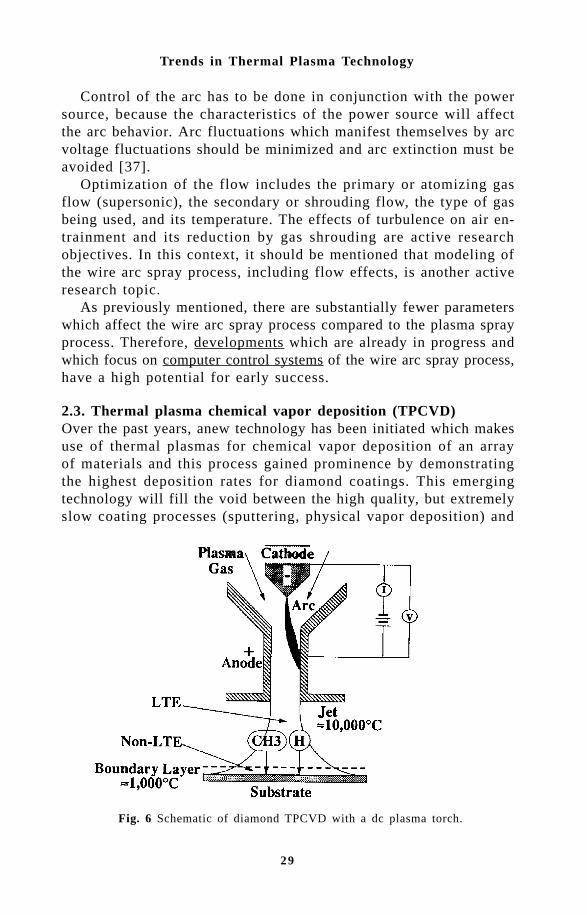
2.3. Thermal plasma chemical vapor deposition (TPCVD)Over the past years, anew technology has been initiated which makesuse of thermal plasmas for chemical vapor deposition of an arrayof materials and this process gained prominence by demonstratingthe highest deposition rates for diamond coatings. This emergingtechnology will fill the void between the high quality, but extremelyslow coating processes (sputtering, physical vapor deposition) and
Fig. 6 Schematic of diamond TPCVD with a dc plasma torch.

30
Thermal Plasma Torches and Technologies
the rapid, but difficult to control thermal spray processes.Because of its unique features, TPCVD may find numerous ap-
plications and some of them are already considered for industrial fab-rication as, for example, diamond and dense ceramic or supercon-ducting films. There are indications that TPCVD may play an im-portant role in the fabrication of nanostructured films. As this emergingtechnology further matures, there is no doubt that other applicationswill come into the picture.
In the process of TPCVD, a high energy density plasma produceshigh density vapor phase precursors for the deposition of relativelythick films. A typical arrangement for TPCVD is shown in Fig. 6In this case, a d.c. plasma torch generates a high temperature, highvelocity plasma jet which impinges on a cooled substrate. With tem-peratures close to the torch nozzle exit exceeding 104 K, the precursormaterial, which is injected into the plasma, is rapidly vaporized anddue to the high velocities of the plasma jet (in the order of 100 m/s), accelerated towards the substrate. In front of the cooled substrate,a boundary layer forms, characterized by steep gradients. Such boundarylayers in chemically reacting gases attracted strong interest in connectionwith space flight and re-entry simulation and, therefore, sub boundary
Fig 7. Schematic of the triple-torch plasma reactor for TPCVD.

31
Trends in Thermal Plasma Technology
layers have been extensively analyzed [38].Besides d.c. plasma jets, other types of plasma reactors have been
also utilized which make use of high frequency (r.f.), hybrid and mi-crowave plasmas. For increasing the available plasma volume, multipletorch arrangements have been developed. A typical reactor with threetorches mounted in a way that the three jets coalesce to form an extendedplasma region (Fig. 7), and with reactant injection through a wa-ter-cooled probe into the region where the three jets merge has beenused for a parametric study of the influence of the process param-eters on the film characteristics [39,40].
Typical power levels have been 36 kW total power, and deposi-tion rates of 40 to 60 µm/hr are achieved at reactor pressures of 270Torr. This reactor has also been used for the homoepitaxial growthof diamond films with growth rates of 100 to 200 µm/hr [41,42].
As an example, Fig. B shows typical diamond films produced inthis reactor without (Fig. 8a) and with (Fig. 8b) secondary precursorinjection. Secondary precursor injection through a ring surroundingthe plasma plume (Fig. 7) provides more uniform precursor distri-bution over the substrate surface which has a pronounced effect onthe surface morphology of the deposited films. Figure 8b indicatesan almost uniform film morphology over the entire substrate diameter(30 mm).
Present research efforts dealing with this emerging technology are
Fig. 8a. Micrographs of diamond films deposited with the triple torch plasma reactorwithout secondary precursors.Fig. 8b. Micrographs of diamond films deposited with the triple-torch plasma reactorwith secondary precursors.

32
Thermal Plasma Torches and Technologies
primarily concerned with establishing the knowledge base, necessaryfor further developments. Both experiments and modeling efforts considerthe chemistry in the boundary layer in front of a substrate in orderto find the most important growth species and to assist in understandingof the growth process. In the case of diamond CVD, growth rate andcrystal structure and orientation as a function of the governing parametersare some of the most important research topics.
As an example, Fig. 9 shows an arrangement of the precursor speciesin front of a substrate during diamond deposition from plasma. [4]Similar arrangements may use one or several arcs as the plasma source.These arrangements are very useful for manipulating the thicknessof the boundary layer in front of the substrate by varying the ar-gon injection flow rate through the injection probe indicated in Fig.9. By increasing the argon flow rate and keeping the other parametersthe same, the boundary layer thickness may be reduced and theeffect of this reduction on the boundary layer chemistry may bedetermined. Corresponding modeling work shows that the importanceof hydrocarbon and carbon species for diamond deposition as thethickness of the boundary layer changes as shown in Fig.10. Both
Fig. 9. R.F. plasma reactor for TPCVD of diamond films with attached Quadropolemass spectrometer [43,44].

33
Trends in Thermal Plasma Technology
the growth chemistry and the growth rate are strongly affected bythe thickness of the chemically reacting boundary layer in frontof these substrates.
For relatively thick boundary layers (2 mm), the model predictsdiamond growth rates of 10 µm/hr in accord with experimental data,with the dominant growth species being methyl. For very thin boundarylayers (=0.1 mm) the model predicts diamond growth rates of severalhundred µm/hr, with a transition to monatomic carbon as the dominantgrowth species as shown in Fig. 10 [45,46].
2.3.1. Summary of present R&D efforts in TPCVDPresent research efforts focus on three aspects;
a.) Boundary and substrate surface chemistry As previously men-tioned, both experiments and modeling efforts have been concentratingon finding the primary growth species in front of the substrate inconjunction with modeling of the boundary layer and surface chemistry.This does not only apply to the deposition of diamond films, but alsoto TPCVD of other materials.
b.) Control of film morphology and film quality are current re-search topics in this field. Film quality is of particular concern foroptical and electronic applications of diamond films.
c.) Film growth rates and film adhesion. Although film deposi-tion using thermal plasmas as a tool for generating growth species,
Fig. 10 Individual precursor’s contribution to diamond growth [45,46].

34
Thermal Plasma Torches and Technologies
result in rather high growth rates, the quality of the deposited filmsmay or may not be sufficient for the intended application. Produc-ing high quality films at high growth rates remains still a challenge.Film adhesion Is one of the major problems in the field of diamonddeposition, especially for deposition on substrate materials which cannottolerate high temperatures (< 5000 °C) and on a variety of metal-lic substrates such as, for example, steel [47], by using intermedi-ate layers of materials to which diamond tends to adhere well (forexample, Mo), or by using metallic binder materials [48,49], the adhesionproblem may be avoided.
Although there is no clear-cut line between research and devel-opment, this line is even more blurred in the case of TPCVD.Developments in this area have been particularly visible in diamondfilm fabrication. Free-standing diamond wafers produced by TPCVDare already commercially available with diameters up to 25 cm. Coatingof complex three-dimensional shapes is a difficult, hut not insurmountableproblem and corresponding efforts are already in progress.
As with most emerging technologies, economic considerations maybe the overriding concern for new developments. This has been thecase, for example, in the field of diamond film developments. Theinitially predicted growth of the market in this field did not mate-rialize.
Similar as in the case of plasma and wire arc spraying, completecontrol of the TPCVD process is the ultimate goal of R&D efforts.
# !!$!!Thermal plasmas which are a source of very high temperatures andsteep temperature gradients offer an attractive and chemically non-specific route for the synthesis of fine powders down to the nanometersize range.
The supersaturation of vapor species, which provides the drivingforce for particle condensation, can be very large in thermal plasmas,leading to the production of ultrafine particles by homogeneous nucleation.Ceramic powders such as carbides, nitrides, oxides, and solid so-lutions have been successfully synthesized in thermal plasma reac-tors. Thermal plasmas suitable for the synthesis of fine powders areprimarily produced by means of high-intensity arcs (a.c. or d.c.) andhigh-frequency discharges (r.f. and microwave).
The high temperatures in thermal plasma reactors lead to shortprocessing times which translates into relatively small reactors withhigh throughput. In spite of this and other advantages of thermal plasmareactors, the high processing costs compared to competing processes

35
Trends in Thermal Plasma Technology
must be offset by superior properties of the products. In general, onlyhigh value-added products are economically viable.
Recent advances in novel reactor and process designs have enhancedthe quality of powders produced in thermal plasmas. These novel designsinclude the r.fl-d.c. hybrid reactor [50], the reactive submerged arc(RSA) [51], multiple plasma jets, and counter-flow liquid-injectionplasma reactors. They aim at maximizing the heating, the mixing,and the residence time of materials in the plasma. Either the dischargeitself or the plasma flame downstream of the discharge may be usedfor synthesizing the powders. In thermal plasma synthesis, the re-actants may be gases, liquids, or solids before injection into the plasma.However the availability of gas-phase precursors for metals is se-verely limited. Therefore, the most commonly used reactants for plasmasynthesis have been solids. Several years ago, a liquid-injection method
Fig. 11. Schematic of the counter flow plasma reactor for injection of liquid precunsors.

36
Thermal Plasma Torches and Technologies
was developed to overcome the problems associated with solid in-jection and to capitalize on the benefits of gaseous reactants [52].
In this case, a conventional d.c. plasma torch produces a high-temperature plasma jet, usually of an inert gas (Fig. 11). The at-omized liquid-precursor material is injected from the end opposingthe plasma jet as a fine mist in counter flow into the plasma, whichgives rise to a recirculation vortex. The recirculation provides ex-tended dwell time of the precursor in a relatively hot zone, assur-ing complete vaporization and dissociation of the precursor mate-rials. The rapid quench downstream of the hot zone induces super-saturation of the dissociated precursor vapor, which in turn, leadsto the desired chemistry and to the formation of fine powder par-ticles via homogeneous nucleation. The powder is collected in thewater-cooled collection chamber and in a filter attached to the outletof this chamber The same basic principle is used in other reactorconfigurations and with other than liquid-precursor materials.
In the past, most of the oxide-synthesis work concentrated onbinary compounds. Large-scale production of TiO2 (pigment) has
Fig.12. Schematic of plasma reactor for the synthesis on nanometer size particles[61].

37
Trends in Thermal Plasma Technology
been pursued for many years by Tioxide in the United Kingdomusing MW-sized arc gas heaters.
With the advance of liquid-injection plasma synthesis within thelast eight years, ternary, quaternary, and higher component oxide solidsolutions including spinels of aluminates, ferrites, and chromites [52-55], and the high-temperature oxide superconductors [52,56-59], havebeen synthesized in both d.c. and r.f. plasmas. Besides these more‘exotic’ oxide compounds, there has been little activity in thermal-plasma synthesis of oxides.
In contrast to the synthesis of oxide powders, there are strong andcontinuing efforts in thermal-plasma synthesis of nonoxide ceramicpowders. The strongest interest seems to be in nitrides, followed bycarbides and finally borides. The most common reactants for ther-mal-plasma synthesis of nonoxide ceramics are solids and metal halides[60].
Recently an experiment has been described in which a plasma con-taining vapor-phase precursors was expanded through a nozzle witha hot ceramic wall [61] as schematically shown in Fig. 12. This ar-rangement approaches a configuration of one-dimensional flow withone-dimensional temperature gradients in the direction of the flowin the nozzle, leading to high uniformity of the quench rate. Furthermore,a nozzle provides much higher quench rates than would be obtain-able otherwise. Using this arrangement, ultrafine SiC particles havebeen synthesized with SiCl
4 and CH
4 as reactants. The results show
that the particles produced in the process have a narrow size dis-tribution peaking at a few nanometers. Both SiC and Si particles havebeen produced with median diameters of 8.5 nm and with 90% ofthe particles having diameters of less than 16 nm.
3.1. Summary of present R&D efforts in thermal plasmasynthesisPresent research efforts concentrate on non-oxide powders (nitrides,carbides) and on new approaches for the synthesis of nanometer sizeparticles. The future growth of this technology will hinge to a largeextent on the development and implementation of effective controls.
This includes control of the particle size and size distribution aswell as of the morphology of the produced powders. Novel reactordesigns are of great interest as, for example, multiple torch arrangements,hybrid reactors combining d.c. torches with r.f. torches and otherinnovative designs which should not only improve the quality of theproduct, but also enhance the efficiency of the process.

38
Thermal Plasma Torches and Technologies
Recent developments are primarily concerned with the scale-up ofplasma reactors and with automatic control of the process.
% !!The following conclusions are restricted to the areas which have beencovered by this overview, i.e., (2) thermal plasma coating technologiesand (2) thermal plasma synthesis of fine powders.
In general, the growth of thermal plasma technologies has beenhampered by the lack of controls. It is felt that synergistics betweenbasic research and development will be crucial for the implementationof controls. This implementation will have a strong impact on thegrowth of thermal plasma coating technologies.
Developments in plasma synthesis will also benefit from bettercontrols, and it is anticipated that the focus of research in this areawill be increasingly towards nanometer-structured materials.
& '( "!A number of colleagues and present and former graduate students contributedto the material presented in this overview. Their contributions, as wellas the support from NSF and DOE, are gratefully acknowledged.
6. References1. R. Spores and F. Pfender, “Flow Structure of a Turbulent Thermal Plasma
Jet”, Surf Coat Technol., 37, pp.251-270 (1989).2. R. Spores, “Analysis of the Flow Structure of a Turbulent Thermal Plasma
Jet”, Ph.D. Thesis, University of Minnesota-Minneapolis (1989).3 F. Pfender, J. Fincke, and R. Spores, “Entrainment of Cold Gas into
Thermal Plasma Jets”, Plasma Chem. Plasma Process., 11(4), pp.529-543 (1991).
4. R.W. Schefer, V. Hartmann, and R.W. Dibble, AIAA 1,25, p. 1318 (1987).5. M. Brossa and F. Pfender, t’Probe Measurements in Thermal Plasma
Jets”, Plasma Chem. Plasma Process., 8(1), pp.75-90(1988).6. SA. Wutzke, “Contidions Governing the Symptomatic Behavior of an
Electric Arc in a Superimposed Flow Field”, Ph.D. Thesis, Universityof Minnesota-Minneapolis (1967).
7. S.A. Wutzke, E. Pfender and E.R.G. Eckert, “Study of Electric-Arc Behaviorwith Superimposed Flow’1, AIAA J, 5(4), pp. 707-714 (1967).
8. M.P. Planche, Z. Duan, 0. Lagnoux, J. Heberlein, P. Fauchais, and E.Pfender, t’Study of Arc Fluctuations with Different Plasma Spray TorchConfigurations”, Proceedings of the 13th International Symposium onPlasma Chemistry, edited by C.K. Wu (Beijing, China) Vol.111, pp.1460-1465 (1997).
9. M.P. Collares and F. Pfender, “Magnetic Probe Measurements in PlasmaSpray Torches”, Proceedings of the 13th International Symposium onPlasma Chemistry, edited by C.K. Wu (Beijing, China) Vol.111, pp.1466-1470(1997).
10. S. Paik, P.C. Huang, J. Heberlein, and E. Pfender, “Determination ofthe Arc-Root Position in a DC Plasma Torch”, Plasma Chem. Plasma
39
Trends in Thermal Plasma Technology
Process., 13(3), pp.379-397 (1993).11 W. Finkelnburg and H. Maecker, “Electric Arcs and Thermal Plasmas’,
Encyclopedia of Physics, vol. XXII, Springer, Berlin (1956).12. Th. Peters, Z Phys, 144, p.612 (1956).13. S. Malmberg, “Analysis of the Plasma Jet Structure, Particle Motion,
and Coating Quality During dc Plasma Spraying”, Ph.D. Thesis, Universityof Minnesota-Minneapolis (1994).
14. P. Fauchais, I.F. Coudert, and M. Vardelle, “Diagnostics in ThermalPlasma Processing”, Plasma Diagnostics, vol. I, edited by 0. Ancielloand D.L. Flamm, Academic Press, New York (1989).
15. D.B. Spalding, “Two-Fluid Models of Turbulence”, CFDU Report CFDI8S/4, CPDU, Imperial College, London (1985).
16. D.B. Spalding, “A Turbulence Model for Buoyant and Combusting Flows”,CFDU Report CFD/86/4, CFDU, Imperial College, London (1986).
17. D.B. Spading, Zeit. Physiochem. Hydrodynam., 4, p.323(1983).18. P.C. Huang, J. Heberlein, and F. Pfender, “A Two-Fluid Model of Turbulence
for a Thermal Plasma Jet”, Plasma Chem. Plasma Process., 15(1),pp.25-46(1995).
19. P.C. Huang, “A Turbulent Swirling Arc Model and a Two-Fluid TurbulenceModel for Thermal Plasma Sprays”, Ph.D. Thesis, UniversityofMinnesota~Minneapolis (1993).
20. D. Apelian, D. Wei, and M. Paliwal, Thin Solid Films, 118, p.395 (1984).21. Y.P. Chyou and F. Pfender, 'Behavior of Particulates in Thermal Plasma
Flows, Plasma Chem. Plasma Process., 9(1), pp.45-71(1989).22. O.P. Solonenko, “Fulerian and Lagrangian Modelling of Dust-Laden Plasma
Jets”, Proceedings of the 13th International Symposium on PlasmaChemistry, edited by C.K. Wu (Beijing, China) Vol.111, pp.1471-1473(1.997).
23. C.H. Chang, ‘1Numerical Simulation of Alumina Spraying in Argon-IleliumPlasma Jetit, Proceedings of the International Thermal Spray Conference(Orlando, Florida) p.793 (1992).
24. J.H. Park, Z. Duan, J. Heberlein, E. Pfender, Y.C. Lau, and H.P. Wang,“Modeling of Fluctuations Experienced in N2 and N2/H2 Plasma Jets IssuingInto Atmospheric Air”, Proceedings of the 13th International Sympo-sium on Plasma Chemistry, edited by C.K. Wu (Beijing, China) Vol.1,pp.326-331 (1997).
25. P. Fauchais, AC. Liger, M. Vardelle, and A. Vardelle, “Formation ofPlasma-Sprayed Oxide Coatings”, Proceedings of the lulian SzekelyMemorial Symposium on Materials Processing and the TMS Fall Ex-traction & Processing Conference, edited by H.Y. Sohn, J.W. Evans,and D. Apelian, (Cambridge, Massachusetts) pp.571-592 (October 1997).
26. H.-D. Steffens, Z. Flabiak, and M. Wewel, IEEE Trans. Plasma Sci.,18(6), p.974 (1989).
27. M.L. Thorpe, J. Mat Process., 134, p.69 (1988).28. D.R. Marantz and D.R. Marantz, Proceedings of the 3rd National Thermal
Spray Conference, p. 113 (1990).29. E. Sampson and L. Neider, Proceedings of the 5th National Thermal
Spray Conference, p.271(1993).30. P.R. Sampson, Proceedings of the 5th National Thermal Spray Con-
ference, p. 257 (1993).31. X. Wang, J. Hebericin, E. Pfendcr, and W. Gerberich, 1tEffect of Gas
Velocity and Particle Velocity on Coating Adhesion in Wire Arc Spraying’1,
40
Thermal Plasma Torches and Technologies
Proceedings of the 9th National Thermal Spray Conference, ThermalSpray: Practical Solutions for Engineering Problems, edited by C.C.Berndt, published by ASM International, pp. 807-811(1996).
32. x. Wang, J. Heberlein, F. Pfender, and W. Gerberich, “Effect of ShroudedC02 Gas Atomization on Coating Properties in Wire Arc Spray”, Pro-ceedings of the 8th National Thermal Spray Conference (Houston, Texas),pp.31-37(1995).
33. R.F. Heile and D.C Hill, Welding J., pp. 201-205 (1975).34. P.J. Wewitt and A.A. Hirst, Ann. Occup. Hyg., 37, p.297 (1993).35. M. Ushia, K. Nakata, M. Tanaka, H. Tong, and T. Mita, Trans JWRI,
23, p.21 (1994).36. T. Watanabe, X. Wang, J. Heberlein, and F. Pfender, “Fume Generation
Mechanism in Wire Arc Spraying”, Proceedings of the 12th Interna-tional Symposium on Plasma Chemistry, edited by J.V. Heberlein, D.W.Ernie, and J.T. Roberts (Minneapolis, Minnesota) Vol.11, pp.889-894(1995).
37. T. Watanabe, X. Wang, J. Heberlein, E. Pfender, and W. Herwig, “Voltageand Current Fluctuations in Wire Arc Spraying as Indications for CoatingProperties’, Proceedings of the 9th National Thermal Spray Confer-ence, Thermal Spray: Practical Solutions for Engineering Problems,edited by C.C. Berndt, published by ASM International, pp.577-583 (1996).
38. E.R.G. Eckert and F. Pfender, “Advances In Plasma Heat Transfer,Advances in Heat Transfer, 4, pp.229-313 (1967).
39. Z.P. Lu, J. Heberlein, and P. Pfender, “Process Study of Thermal PlasmaChemical Vapor Deposition of Diamond, Part I. Substrate Material,Temperature, and Methane Concentrationt’, Plasma Chem. Plasma Proc.,12(1), pp. 35-52(1992).
40. Z.P. Lu, J. Heberlein, and E. Pfender, “Process Study of Thermal PlasmaChemical Vapor Deposition of Diamond, Fart II; Pressure Dependenceand Effect of Substrate PreTreatment”, Plasma Chem. Plasma Proc.,12(1), pp.55-69(1992).
41. KA. Snail, CM. Marks, Z.P. Lu, 1. Heberlein, and F. Pfender, “HighTemperature, High Rate Homoepitaxial Synthesis of Diamond in a ThermalPlasma Reactor”, Mater. LetL, 12, pp.301-305 (1991).
42. Z.P. Lu, K. Snail, C. Marks, J. Heberlein, and B. Pfender, “High RateHomoepitaxial Growth of Diamond in Thermal Plasma”, Proceedingsof the 2nd International Symposium on Diamond Materials (TheElectrochemical Society, Washington, D.C.) Vol.91-8, pp.99-106(1991).
43. P. Gruel, H. Yoon, D. Ernie, and J. Roberts, Map Res. Soc. Symp.Proc., 334, p.141(1994).
44. P.O. Gretiel, J.T. Roberts, and D.W. Ernie, “Mass Spectrometric Analysisofa Thermal Plasma Used for CVD of Diamond Films”, Proceedingsof the 12th International Symposium on Plasma Chemistry, edited byJ.V. Heberlein, D.W. Ernie, and J.T. Roberts (Minneapolis, Minnesota)Vol. IV, pp.2209-2214 (1995).
45. B.W. Yu, “A Model for Chemical Vapor Deposition of Diamond in aRadio-Frequency Induction Thermal Plasma”, Ph.D. Thesis, Universityof Minnesota-Minneapolis (1994).
46. B.W. Yu and S.L. Girshick, “Atomic Carbon Vapor as a Diamond GrowthPrecursor in Thermal Plasmas”, J Appl. Phys., 75, pp.3914-3923 (1994).
47. M. Asmann, C.F.M. Borges, J. Heberlein, and F. Pfender, “Thermal Plasma
41
Trends in Thermal Plasma Technology
Chemical Vapor Deposition of Diamond on Steel, Proceedings of the13th International Symposium on Plasma Chemistry, edited by C.K.Wu (Be4ing, China) Vol.111, pp. 1206-1211(1997).
48. C. Tsai, J. Nelson, W. Gerberich, I. Heberlein, and F. Pfendder, “MetalReinforced Thermal Plasma Diamond Coatings”, J. Mater. Res., 7, pp.1967-1969(1992).
49. C. Tsai, J.C. Nelson, W.W. Gerberich, I. Heberlein, and F. Pfender,“Diamond-Metal Composite Coatings on Cemented Carbide Tools’, DiamondRelated Mater., 2, pp.617-620(1993).
50. T. Yoshida, T. Tani, H. Nishimura, and K. Akashi, J Appl. Phys., 2,p.640(1983).
51. A. Kumar and R. Roy, J Mater Res, 3(6), p.1373(1989).52. P. Kong and F. Pfenden Proceedings of the 2nd Int. Conf. Ceram. Powder
Processing Sci. (Berchtesgaden, 1988).53. P. Kong and B. Pfender, “Plasma Synthesis of Fine Powders by Counter-
Flow Liquid Injection’, Combustion and Plasma Synthesis of High Tem-perature Materials, edited by Z.A Munir and J.B. Holt (VCH Publish-ers, Inc., New York) pp.420-430 (1990).
54. P. Kong, T. Or, L. Stachowicz, and B. Pfender, “Better Ceramics ThroughChemistry IV’, Mater. Res. Soc. Symp. Proc., edited by B.J.J. Zelinski,C.J. Brinker, D.E. Clark, and D.R. Ulrich (Pittsburgh, PensyIvania) 180,p.849(1990).
55. T. Or, Z. Lu, L. Stachowicz, P. Kong, and E. Pfender, “Plasma Processingand Synthesis of Materials III”, Mater. Res. Soc. Symp. Proc., editedby D. Apelian and J. Szekely (Pittsburgh, Pennsylvania) 190, p.83 (1991).
56. H. Zhu, Y.C. Lau, and F. Pfender, “RF Plasma Synthesis of YBa2Cu3O7
Powders'', J Supercond, 3, pp.171-175 (1990).57. K. Terashima, T. Yoshida, and K. Akashi, Jpn. Symp. on Plasma Chemistry,
p. 57 (1988).58. T. Ono, M. Kagawa, Y. Syono, M. Ikebe, and Y. Muto, “Ullrafine Powders
Prepared by the Spray-ICP Technique’t, Plasma Chem. Plasma Process.,7(2), pp. 201-209 (1987).
59. H. Zhu, Y.C. Lau, and E. Pfender, “Deposition of YBa2Cu3O7-x Thick Filmsby the Spray-JCP Techniquet’, Proceedings of the 9th InternationalSymposium on Plasma Chemistry, edited by R. dAgostino (Pugnochdso,Italy) Vol.3, pp.1497-1502(1989).
60. P.C. Kong and B. Pfender, ‘Chapter 14: Plasma Processes’, Carbide,Nitride and Boride Materials Synthesis and Processing, edited by A.W.Weirner, published by Chapman & Hall, London (1997).
61. N. Rao, S. Girshick, I. Heberlein, P. McMurry, S. Jones, D. Hansen,and B. Micheel, 'Nanoparticle Formation Using a Plasma ExpansionProcess', Plasma Chem. Plasma Process., 15(4), pp.581-606 (1995).

42
Thermal Plasma Torches and Technologies
Maher I. BoulosPlasma Technology Research Centre (CRTP), Dept. of Chemical Engineering, Universitéde Sherbrooke, Sherbrooke, Québec, J1K 2R1, CANADA
A review is presented of advances in induction plasma torch designs and systemanalysis. Emphasis is placed on recent studies dealing with a turbulent, threeequation, k-e model formulation which was successfully used for the representationof the flow, temperature and concentration fields in the discharge under high plasmagas flow rates and power levels. When combined with a power supply model,an integrated system analysis is described, which allows the plasma conditionsto be linked to the electrical parameters of the power supply. The proposed approachprovides a valuable tool for integrated induction plasma design and parameteroptimization.
The radio frequency (r.f.) inductively coupled plasma source has beenthe subject of numerous studies for more than half a century. Its earlydevelopment can be traced back to Babat [1] in 1947 and Reed [2]in 1961. Since then, important developments have been made in thefollowing four principal areas:
Aerospace research for nuclear rocket simulation and the test-ing of materials for thermal shields of space vehicles. Installationsin the MW power range were built for this purpose in the USA andin the former Soviet Union in the 60’s and 70’s. These were mostlyoperated under low pressure with Argon or Air as the plasma gas.
Analytical applications of the inductively coupled plasma (ICP)for elemental analysis using ICP/Atomic Emission spectroscopy (AE)or ICP/Mass Spectrometry (MS) techniques. The plasma sourcesdeveloped for these applications were generally of low power (1 to5 kW), operated at a frequency of 27.3 MHz or higher. The plasmagas was mostly argon, helium or nitrogen. Thousands of such installationsare presently in operation around the world.

43
Integrated Analysis of Induction Plasma Systems
Induction plasma processing of materials. This area was startedin the seventies with the development of novel techniques for the pro-duction of high purity synthetic quartz for fiber optics. In the eightiesand nineties, attention was shifted to metal and ceramic processingin general whether for powder spheroidization and densification, InductionPlasma Vacuum Spraying (IPVS), Induction Plasma Reactive Deposition(IPRD), Suspension Plasma Spraying (SPS), Plasma Flash Vapori-zation and Deposition (PFVD) and the induction plasma synthesisof ultra-fine powders (UFP).
Induction plasma treatment of waste materials. Technology hasrapidly developed in this area in the late eighties and nineties. Thesewere mostly dedicated to the destruction of military waste materi-als, or the destruction of chloro-fluorocarbons, and more recently water-based waste materials.
Successful applications of induction plasma technology in eachof these areas depended, however, on the availability of efficient andreliable sources for plasma generation and a fundamental understandingof the basic phenomena involved. A review is presented in this pa-per of recent advances in induction plasma torch design and math-ematical modeling with emphasis on a novel integrated approach forthe analysis of induction plasma systems as a whole taking into accountthe interactions between the plasma torch and the power supply.
!"#$%$!"$The availability of a reliable plasma generating device is a keyrequirement for any significant industrial process development. Plasmatorch development, on the other hand is often motivated by significantpotential for research and industrial applications. The induction plasmahas been no exception in this respect with early torch developmentwork mostly funded by NASA in the late sixties and early seventiesfor its aerospace programs. M. Thorpe of TAFA Corporation in N.H.USA, Reboux in France, and S. Dresvin of St. Petersburg TechnicalUniversity in Russia, have been of the leading researchers in this areato whom many of the early developments are credited. The main featuresof the early induction plasma torch designs include the use of a quartzplasma confinement tube combined with a wide range of plasmastabilization techniques schematically represented in Figure 1.
The specific design and the nature of the plasma confinement tubeand of the intermediate separator tube have varied over the years.The simplest torch designs used quartz, air or water-cooled, for theplasma confinement tube. Their main limitation was mostly in thedifficulty of scaling up to higher power levels in the hundreds kW,

44
Thermal Plasma Torches and Technologies
Fig.1 Commonly used induction plasma stabilization techniques (after Dresvin [3]).
and their lack of reliability for long service operation. Alternate torchdesigns were developed over the past twenty years along the followinglines:
Metal wall torches in which the quartz plasma confinement tubeis protected by a segmented, water-cooled, metal wall. Figure 2 showsearly designs which were developed in the seventies in the formerSoviet Union. Their energy efficiency is, however, lower than alternateceramic or quartz tube torches due to ohmic losses in the metal wallsegments. They are also more difficult to ignite and are less toler-ant to variations of the chemistry of the plasma gases which can becontaminated by the metal wall.
Ceramic wall torches in which the quartz plasma confinement tubeis replaced by an appropriate ceramic with a high thermal conduc-tivity and thermal shock resistance. This patent protected design shownin Figure 3, developed at the CRTP at the Université de Sherbrookein the eighties also involves the moulding of the induction coil ina polymer-matrix composite, which gives a rugged and reliable torchdesign with high energy efficiency. Torches of this type are presentlydesigned and manufactured on a commercial scale by Tekna PlasmaSystems Inc. in Sherbrooke, Quebec for power rating varying between30 kW to 400 kW. This design allows for the addition of differenttorch nozzles to control the flow pattern in the emerging plasma jet.
Hybrid plasma torches. These have been developed by Profes-

45
Integrated Analysis of Induction Plasma Systems
Fig.2 Typical design of the metal wall induction plasma torch (after Dresvin [4]).
Fig.3 Ceramic wall induction plasma torch developed at the CRTP, Université deSherbrooke
Powder + carrier gas
Central gas
Torch coolingwater IN
Intermediate tube
Powder injection probe
Plasma confinement tube
Gas distributor head
Sheath gas
Torch coolingwater OUT
Torch body
Coil water OUT
Coil water IN
Induction coil
Exit nozzle

46
Thermal Plasma Torches and Technologies
RF coil
Quartz tubes
DC power supply
Out
In
Fig.4 D.c. / r.f. hybrid plasma torch (after Yoshida et al. [5]).
sor T. Yoshida at the University of Tokyo in Japan in the late sev-enteen and early eighteen. The d.c./r.f. hybrid torch shown in Fig-ure 4 after Yoshida et al. [5], features a d.c. torch operating in com-bination with an r.f. induction plasma torch on which it is co-axi-ally mounted. The power to the d.c. torch is generally limited to 5or 10 % of the total plasma power. This design gives rise to higherenergy density in the center of the discharge at the expenses of in-troduction of low level metallic contaminants in the flow due to electrodeerosion of the d.c. plasma torch. An r.f./r.f. hybrid plasma designwas developed by Kameyama et al. [6]. The d.c. torch in this caseis replaced by a second r.f. induction torch operated at a higher oscillatorfrequency than that of the main discharge. Such a design eliminatesthe source of contamination of the flow at the expense of a considerableincrease in complexity.
&"#$"!"$!' ( $'$#Mathematical modeling is an important tool in thermal plasma studies.It provides means for the understanding of flow, temperature andconcentration fields in plasma flows and gas mixing phenomena. Anumber of models were developed over the years for the inductivelycoupled r.f. plasma source. These were generally based on a laminar,two-dimensional, steady state representation of the plasma under localthermodynamic equilibrium conditions [7,8]. Over the past ten years,attention was also given to the development of turbulent flow models[9-12] and the use of an integrated approach for the modeling of the

47
Integrated Analysis of Induction Plasma Systems
induction plasma system [12,14-16]. The latter involved the modelingthe magneto-hydrodynamics of the discharge and its interaction withthe electrical characteristics of the power supply circuit. In the following,a brief description is given of recent advances in this area.
3.1 Plasma dynamic modelsThe principal difficulty in the development of a generalized mathematicalmodel of the inductively coupled plasma lies in the fact that whilelaminar flow models are satisfactory at low plasma gas flow ratesand plasma power levels, they are generally inadequate at high flowand power conditions. The difficulty is due to the fact that as theplasma power is increased with an associated increase of the plasmagas flow, laminar-to-turbulent transition, is observed in the lowtemperature regions of the flow, with the conditions in the hightemperature regions of the discharge remaining predominantly laminar.The simultaneous presence of these two distinct flow regions offersan added complexity in terms of model convergence. In recent studiesby Chen et al. [10,11], Merkhouf et al. [12] and Ye et al. [13], athree equation (3E) turbulence fluid model was proposed taking intoaccount the density fluctuations in the plasma. The model makes useof the standard k-e turbulence formulation. The following assumptionswere made:
· Steady state and isotropic turbulent flow;· Axi-symmetric two-dimensional system of coordinates;· Plasma is in local thermodynamic equilibrium (LTE) condition;· The plasma is optically thin;· The thermodynamic and transport properties have no fluctuations
except for the density;· The viscosity dissipation of the thermal energy is negligible.
3.1.1 Governing equationsThe governing equations for the 3E fluid model are briefly describedas follows (in the equations, the dependent variables with a bar denotethe conventional time-averaged quantities, others are the density-weightedaveraged quantities, see Merkhouf et al. [12], and Ye et al. [13]):
(a) Continuity equation
( ) ( ) 01 =
∂∂+
∂∂
vrrr
uz
ρρ (1)
(b) Momentum conservation equations
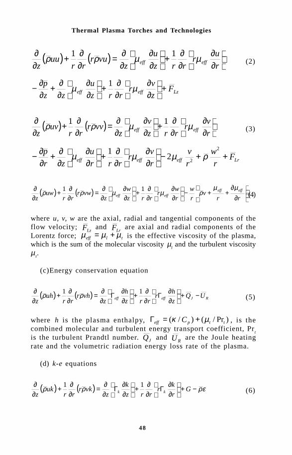
48
Thermal Plasma Torches and Technologies
( ) ( )
∂∂
∂∂+
∂∂
∂∂=
∂∂+
∂∂
r
ur
rrz
u
zvur
rruu
z effeff µµρρ 11 (2)
Lzeffeff Fz
vr
rrz
u
zz
p +
∂∂
∂∂+
∂∂
∂∂+
∂∂− µµ 1
( ) ( )
∂∂
∂∂+
∂∂
∂∂=
∂∂+
∂∂
r
vr
rrz
v
zvvr
rruv
zeffeff µµρρ 11
(3)
Lreffeffeff Fr
w
r
v
r
vr
rrr
u
zr
p ++−
∂∂
∂∂+
∂∂
∂∂+
∂∂−
2
22
1 ρµµµ
( ) ( )
∂
∂++−
∂∂
∂∂+
∂∂
∂∂=
∂∂+
∂∂
rrv
r
w
r
wr
rrz
w
zvwr
rruw
zeffeff
effeff
µµρµµρρ 11
(4)
where u, v, w are the axial, radial and tangential components of theflow velocity;
LzF and LrF are axial and radial components of the
Lorentz force; tleff µµµ += is the effective viscosity of the plasma,which is the sum of the molecular viscosity µ
l and the turbulent viscosity
µt.
(c)Energy conservation equation
( ) ( ) RJeffeff UQz
hr
rrz
h
zvhr
rruh
z−+
∂∂Γ
∂∂+
∂∂Γ
∂∂=
∂∂+
∂∂ 11 ρρ (5)
where h is the plasma enthalpy, )Pr/()/( ttpeff C µκ +=Γ , is thecombined molecular and turbulent energy transport coefficient, Pr
t
is the turbulent Prandtl number. JQ and RU are the Joule heating
rate and the volumetric radiation energy loss rate of the plasma.
(d) k-e equations
( ) ( ) ερρρ −+
∂∂Γ
∂∂+
∂∂Γ
∂∂=
∂∂+
∂∂
Gr
kr
rrz
k
zvkr
rruk
z kk
11 (6)

49
Integrated Analysis of Induction Plasma Systems
( ) ( )k
Ck
GCr
rrrzz
vrrr
uz
2
21
11 ερεεεερερ εεεε −+
∂∂Γ
∂∂+
∂∂Γ
∂∂=
∂∂+
∂∂
(7)
where )Pr/( ktlk µµ +=Γ , )Pr/( εε µµ tl +=Γ , are the combinedtransport coefficients for the turbulent kinetic energy k and its dissipationrate ε, respectively, ερµ µ /2kCt = ; Pr
k and Pr
e are the corresponding
Prandtl numbers. G is the generation rate of the turbulent kinetic energy.
∂∂+
∂∂+
∂∂+
∂∂+
+
∂∂+
∂∂=
222222
2z
v
r
u
r
w
rr
z
w
r
v
r
v
z
uG tµ (8)
(e) Temperature variance equation
( ) ( ) 222
22 ""1"
"1
" Tk
CGCr
Tr
rrz
T
zvTr
rruT
z TTgeffeff
−+
∂
∂Γ∂∂+
∂
∂Γ∂∂=
∂∂+
∂∂ ερρρ
(9)
where
∂∂+
∂∂=
22
Pr r
T
z
TG
t
tT
µ (10)
is the generation rate for the temperature variance.The constants in the preceding equations (1) – (10) are as fol-
lows: Cµ = 0.9, Cε1 = 1.44, Cε2
= 1.92, Cg = 2.0, C
T = 6.0,
Prk = 1.0, Prε = 1.30, Pr
t = 0.7.
The solution of the above listed fluid dynamic equations requiresa knowledge of the associated electromagnetic fields for the calcu-lation of the Lorentz forces (
LzF and
LrF ), and Joule heating acting
on the plasma (j
Q ). These were computed using the vector potentialformulation of the two-dimensional electromagnetic fields afterMostaghimi and Boulos [8]. This model considers the interaction betweenthe applied magnetic field of the coil and induced magnetic field ofthe plasma. The individual equations for the component for the vectorpotential, Aθ, inside the r.f. discharge are written as:

50
Thermal Plasma Torches and Technologies
01
022
2
=+−
∂∂
∂∂+
∂∂
I
RRR ArA
rA
rrrz
A ωσµ (11)
01
022
2
=+−
∂∂
∂∂+
∂∂
R
III Ar
A
r
Ar
rrz
A ωσµ (12)
where AR and A
I are, respectively, the real and imaginary parts of
the vector potential, r & z are the coordinates in the radial and axialdirections, σ the electrical conductivity of the plasma, µ
0, the magnetic
permeability of free space and ω = 2πf, with, f, the oscillator frequency.The vector potential on the wall and the free space surrounding
the plasma is determined by the superposition of the coil and the plasmaeffects. In the numerical scheme used, the plasma torch is dividedinto a number of control volumes in the form of cylindrical loops,the components of the potential vector on the wall and free spacesurrounding the discharge can be written as:
∑∑==
+=..
1,
1, )(
2)(
2
VC
iiiIi
io
i
coil
i
cco
iR kGSAr
rkG
r
rIA σ
πωµ
πµ
(13)
( )∑=
−=..
1,
0, 2
VC
iiiiRi
ic
iI kGSAr
rIA σ
πµ
with c
rrr ≤≤0 (14)
with
( ) ( )i
iii
i k
kEkkkkG
)(22)(
2 −−= (15)
and
Ki = 4rcri
(rc + ri)2 + (zi − zc)2 (16)
The first summation in Eq. (13) extends over the number of coilturns and the second one extends over the current carrying regionsof the discharge, where I
c is the coil current, z
c is the axial position
of the current loop, K and E are the complete elliptic integrals, r0

51
Integrated Analysis of Induction Plasma Systems
and rc are, respectively, the radius of the plasma confinement tube
and coil and ri and S
i are the radius and cross section of the i
th control
volume. The corresponding electrical field intensity, Eθ, the axial andradial components of the magnetic field H
z and H
r, can be calculated
as follows:
Eη = −jζ Aη (17)
( )θµ rArr
Hz ∂
∂= 10 and ( )θµ A
zH
r ∂∂−=
0 (18)
The r.f. discharge power dissipated in the plasma load, P0:
P E dvv
021
2= s q (19)
3.1.2 Torch geometry and operation conditionsThe rf plasma torch and the corresponding coordinates used by Ye
Fig.5 Torch geometry and system of coordinates (after Ye et al. [13]).
Q1 Q3Q2
r3
r0
Zs
r
z
RF coil
Zp
Z1
Z2
Z3
Z = 0
r1
r2
rc
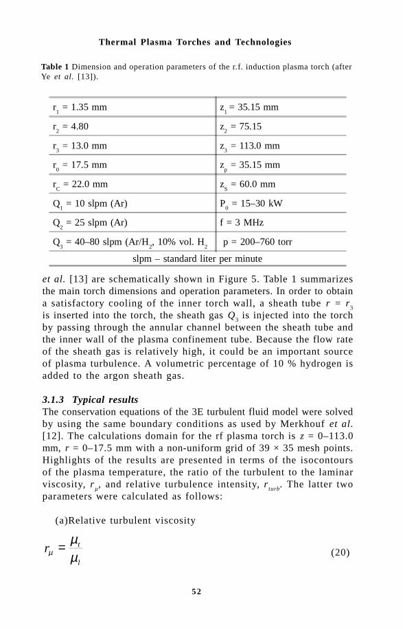
52
Thermal Plasma Torches and Technologies
Table 1 Dimension and operation parameters of the r.f. induction plasma torch (afterYe et al. [13]).
r1 = 1.35 mm z
1 = 35.15 mm
r2 = 4.80 z
2 = 75.15
r3 = 13.0 mm z
3 = 113.0 mm
r0 = 17.5 mm z
p = 35.15 mm
rC = 22.0 mm z
S = 60.0 mm
Q1 = 10 slpm (Ar) P
0 = 15–30 kW
Q2 = 25 slpm (Ar) f = 3 MHz
Q3 = 40–80 slpm (Ar/H
2, 10% vol. H
2 p = 200–760 torr
slpm – standard liter per minute
et al. [13] are schematically shown in Figure 5. Table 1 summarizesthe main torch dimensions and operation parameters. In order to obtaina satisfactory cooling of the inner torch wall, a sheath tube r = r
3
is inserted into the torch, the sheath gas Q3 is injected into the torch
by passing through the annular channel between the sheath tube andthe inner wall of the plasma confinement tube. Because the flow rateof the sheath gas is relatively high, it could be an important sourceof plasma turbulence. A volumetric percentage of 10 % hydrogen isadded to the argon sheath gas.
3.1.3 Typical resultsThe conservation equations of the 3E turbulent fluid model were solvedby using the same boundary conditions as used by Merkhouf et al.[12]. The calculations domain for the rf plasma torch is z = 0–113.0mm, r = 0–17.5 mm with a non-uniform grid of 39 × 35 mesh points.Highlights of the results are presented in terms of the isocontoursof the plasma temperature, the ratio of the turbulent to the laminarviscosity, r
µ, and relative turbulence intensity, r
turb. The latter two
parameters were calculated as follows:
(a)Relative turbulent viscosity
l
trµµ
µ = (20)

53
Integrated Analysis of Induction Plasma Systems
Fig. 6 Temperature field (left) and relative turbulence viscosity (right) for an atmospheric
0 5 10 15
r (mm)
0
20
40
60
80
100
z (
mm
)
1000
0K
8000
K50
00K 20
00K
0 5 10 15
r (mm)
0
20
40
60
80
100
z (
mm
)1
3
5
13
20
(b)Relative turbulence intensity
222int
3/2
wvu
krturb
++= (21)
Figure 6 shows typical temperature isocontours (left) and the cor-responding relative turbulent viscosity field, rµ, (right) for an atmosphericpressure pure argon plasma at a power level of 15 kW and a sheathgas flow rate, Q
3 = 80 slpm (Ar). From a comparison of both sides
of the figure, it may be noted that the flow is highly turbulent inthe upstream cold end of the torch near the entrance of the centralgas, Q
2. In the wall boundary layer in the vicinity of the plasma con-
finement tube, high turbulent viscosities are also observed. These arein the range of 3 to 5 times the local molecular viscosity. Within thedischarge in the coil region, the plasma temperature and consequently,its molecular viscosity, is sufficiently high that laminar flow pre-dominates.
Local distribution of the turbulence intensities in the flow are givenin Figure 7 for two plasma pressure (101.3 kPa and 26.7 kPa). Theplasma power in this case was 15 kW and the sheath gas flow rate= 40 slpm (Ar). High turbulence levels are observed on the upstreamcold side of the discharge and along the wall boundary layer of the

54
Thermal Plasma Torches and Technologies
0 5 10 15
r (mm)
0
20
40
60
80
100
0.1
0.2
0.3
0.1
0 5 10 15
r (mm)
0
20
40
60
80
100
z (
mm
)
z (
mm
)0.1
0.2
0.2
0.3
0.2
0.1
Fig.7 Relative turbulence intensity isocontours for an Argon plasma at 15 kW andQ3 = 40 slpm and (a) pressure = 101.3 kPa (b) pressure = 26.7 kPa (after Ye et al.[13]).
plasma confinement tube. A slight increase in turbulence can alsobe noted at the end of the central powder injection probe which isresponsible for the local cooling of the flow in this region. Higherturbulence levels are also noted at atmospheric pressure comparedto that for low pressure operation.
3.2 Integrated modelThe development of an integrated model of the r.f. induction plasmaaims specifically at predicting the electrodynamic interactions betweenthe plasma and the power supply. For this a detailed analysis of theelectrical characteristics of the discharge is required as well as dynamicmodel of the power supply circuit. Recently, a number of models havebeen proposed for the simulation of the integrated induction plasma– generator system [12,14-16]. With the exception of the study byKim et al. [15], these do not go through the full computation of theflow and temperature fields in the discharge and accordingly do notinclude the inherent changes in the electromagnetic characteristicsof the plasma which may result from changes in the electrical parametersof the power supply circuit. The work of Kim et al. [15], on the otherhand, relies on a laminar flow model which does not allow for the
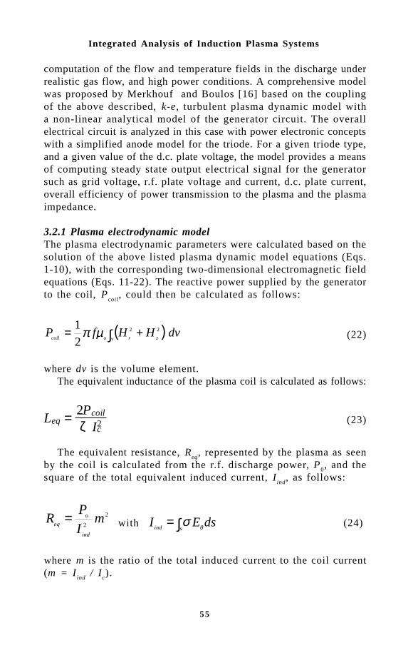
55
Integrated Analysis of Induction Plasma Systems
computation of the flow and temperature fields in the discharge underrealistic gas flow, and high power conditions. A comprehensive modelwas proposed by Merkhouf and Boulos [16] based on the couplingof the above described, k-e, turbulent plasma dynamic model witha non-linear analytical model of the generator circuit. The overallelectrical circuit is analyzed in this case with power electronic conceptswith a simplified anode model for the triode. For a given triode type,and a given value of the d.c. plate voltage, the model provides a meansof computing steady state output electrical signal for the generatorsuch as grid voltage, r.f. plate voltage and current, d.c. plate current,overall efficiency of power transmission to the plasma and the plasmaimpedance.
3.2.1 Plasma electrodynamic modelThe plasma electrodynamic parameters were calculated based on thesolution of the above listed plasma dynamic model equations (Eqs.1-10), with the corresponding two-dimensional electromagnetic fieldequations (Eqs. 11-22). The reactive power supplied by the generatorto the coil, P
coil, could then be calculated as follows:
( )∫ +=v zrocoil
dvHHfP 22
21 µπ (22)
where dv is the volume element.The equivalent inductance of the plasma coil is calculated as follows:
Leq = 2Pcoil
ζ Ic2 (23)
The equivalent resistance, Req
, represented by the plasma as seenby the coil is calculated from the r.f. discharge power, P
0, and the
square of the total equivalent induced current, Iind
, as follows:
2
2m
I
PR
ind
o
eq= with ∫=
sind dsEI θσ (24)
where m is the ratio of the total induced current to the coil current(m = I
ind / I
c).
56
Thermal Plasma Torches and Technologies
The equivalent impedance of the plasma coil, Zeq
, is finally de-rived as:
( ) ( )222 eqeqeq fLRZ π+= (25)
3.2.3 Power supply circuit modelFigure 8 shows a schematic of a typical r.f. power supply circuit.The input power to the oscillator is supplied by the filtered dc currentsupply via the choke coil, L
1, which maintains a constant dc plate
voltage, Vp0
. The load of the generator is composed of the plasmatorch, tank coil, L
2, with internal resistance R
2 and leads, which constitute
an equivalent resistance, Rl, and an inductance, L
l. A capacitor, C
2,
in parallel the load draws up an oscillating circuit. The grid feedbackfactor, k, is defined as the ratio of the alternating grid voltage, V
g,
to the r.f. anode voltage, Vp, which is adjusted mechanically by the
operator, to a value within the limits of (0.1 < k < 0.3)[17]. Thecontrol factor, h, is used for fixing the negative d.c. grid voltage,which depends in turn, on the value of the grid resistance, R
g, and
capacitor, Cg.
In the induction plasma installation, the oscillator circuit is tunedto its natural resonant frequency which can be calculated as:
fL L L Ceq
=+ +
1
2 2 1 2p (26)
Fig.8 Block diagram of the electrical circuit of the r.f. power supply (after Merkhoufand Boulos [16]).
C1Ip0 Vp
L1
V2
L2
I1 IcR2
L
R
Vp0Triode
C2
OscillatorRg Cg
k, h
Grid command circuit
Solid staterectifier
Plasma torch

57
Integrated Analysis of Induction Plasma Systems
At this frequency, the magnitude of the equivalent impedance ofthe tank circuit is given by:
ZL L L
R R R Cco
eq l
eq l
=+ +
+ +2
2 2 (27)
The anode voltage, Vp, is the sum of the d.c. rectifier supply voltage,
Vp0
, and the alternating voltage, V2, formed in the oscillator circuit.
V V V V V tp po= + = -2 2 2with ( ) cos( )max w (28)
The grid voltage, Vg, is the sum of the fixed bias (-kh(V
2)
max) and
the a.c. component (-V2) delivered from the oscillator circuit.
V k V kh V V Vg p= - - =2 2 2 0( ) ( )max maxwith a (29)
The average value of the plate current pulse is given as:
( ) ( ) ( )[ ]ccc
D
p
p kR
VI βββµ
πα
cossin10
0 −−= (30)
where βc is the cut-off angle of the oscillator tube, see Merkhouf and
Boulos [16].The d.c. power input to the plate circuit, P
dc, the fundamental a.c.
output oscillator power, Pos
, and the plate loss in the tube, Pd, are
calculated as:
P V Idc p p= 0 0 (31)
co
M
os Z
VP
2
2
2= (32)
Pd = Pdc − Pos (33)
The plate circuit efficiency, hp, torch coupling efficiency, h
t, and
overall efficiency, h0 are calculated respectively as follows:

58
Thermal Plasma Torches and Technologies
Table 2 Specifications of the tank circuit components (after Merkhouf and Boulos[16]).
C2[nF] µ[–] ρ [Ω] L
2[µH] R
2 [Ω] R
1 [Ω] L
1 [µH] k[–]
1.5 20 700 0.1 0.06 0.01 0.05 0.3
Power supply circuit model
RF induction plasma fluid dynamic model
Yes
No End
Convergence
Req, Leq
f, P0
Triode characteristicsPlate resistance, Rp
Amplification factor, κGrid feedback, k
Coil dimensionPlasma gasDC plate voltage Vp0
Initial P0 and f
Fig.9 Block diagram for the integrated power supply induction plasma model (afterMerkhouf and Boulos [16]).
( )popo
co
dc
os
p IV
ZV
P
P 2/2
max2==η (34)
( )( )[ ]co
cos
os
o
t ZV
IRRP
P
P
2/
5.02
2
2
12+−==η (35)
tpoηηη = (36)
3.2.3 Typical resultsTo calculate the operating point of the r.f. plasma installation, fora given value of the d.c. plate voltage V
p0, both the fluid dynamic
and power supply circuit models have to be solved simultaneously.These are coupled by the hierarchical algorithm schematically representedin Figure 9. The solution procedure is as follows, first the fluid dynamicmodel is solved for a given initial guess of the dissipated power (P
0)

59
Integrated Analysis of Induction Plasma Systems
5 6 7 8 9 10 110.5
0.6
0.7
0.8
0.9
1.0
1.1
0.5
0.6
0.7
0.8
0.9
Inductance [ µ H ]
Plate voltage, Vp0 [kV]
Res
ista
nce
[Ohm
]
Fig.10 Plasma resistance and inductance as function of the plate voltage (after Merkhoufand Boulos [16]).
in the plasma and oscillator frequency (f). The equivalent plasmaimpedance can then be calculated using Eq. 25. The power dissipation(P
0) in the plasma, and frequency (f) are then computed, and new
plasma impedance was recalculated using P0 and f as the input to
the r.f. fluid dynamic discharge model. This procedure was repeateduntil P
0 and f had a constant convergent values.
Results were given by Merkhouf and Boulos [16] for an atmos-phere pressure of pure Argon plasma. The tank circuit componentsspecifications are given in Table 2. Figure 10 shows the variationof the equivalent inductance and resistance of the plasma torch withthe plate voltage (V
p0). It is noted that the inductance drops slowly
when the plate voltage is increased. This is due to the observed increaseof the high temperature region and its shifting closer to the wall ofthe plasma confinement tube. This results in the increase of the crosssection of the plasma through which the magnetic flux penetrates andthe corresponding reduction of the space between the coil and ther.f. discharge which is responsible for the flux leakage. The plasmareactance is compensated automatically by the generator’s tank circuitwhich adjust its frequency to mach the reactive load. The equiva-lent resistance, on the other hand, increased with the increase of theplate voltage. The maximum plasma volume is dependent on the sizeof the torch. The increase in volume means higher resistance, whilea higher mean temperature has the opposite effect. The combined effectof plasma temperature and plasma volume gives rise to the observedslower rate of increase of the plasma resistance with the plate voltageat high values of the plate voltage.
Figure 11 shows the variation of the oscillator efficiency and the

60
Thermal Plasma Torches and Technologies
5 6 7 8 9 10 11
68
70
72
74
76
78
80
0
10
20
30
40
Osc
illat
or e
ffic
ienc
y, η
os[%
]
Anode loss, P
d[kW]
Plate voltage, Vp0 [kV]
Fig.11 Oscillator coupling efficiency and anode loss as function of the plate voltage(after Merkhouf and Boulos [16]).
5 6 7 8 9 10 11
86
87
88
89
90
91
92
93
94
0
20
40
60
80
100
Torc
h c
oup
ling
effi
cien
cy, η
t [%
] Oscillator pow
er, Pos[kW
]
Plate voltage, Vp0 [kV]
anode loss as function of the plate voltage. As expected, the anodeloss in the triode increases rapidly with the increase of the plate voltagewhich in turn reduce the oscillator efficiency. The latter varies between60 % to 80 % depending of the triode tube characteristics and op-erating conditions. Figures 12 and 13 show the variation of the torchefficiency and overall coupling efficiency for the r.f. plasma systemas function of the plate voltage. The torch coupling efficiency in-crease with the increase of the plate voltage. This is due to the increaseof the injected power which gives rise to a corresponding increaseof the volume of the discharge and, consequently, of the cross sectionlinked with the magnetic flux. Since the oscillator power (P
os) is dissipated
respectively in the plasma and in the inductor resistance, the torch
Fig.12 Oscillator power and torch coupling efficiency as function of the plate voltage(after Merkhouf and Boulos [16]).

61
Integrated Analysis of Induction Plasma Systems
5 6 7 8 9 10 11
68
69
70
71
72
73
74
0
20
40
60
80
100
120
Ove
rall
coup
ling
effi
cien
cy, η
o[%
]
Input power, P
dc [kW]
Plate voltage, Vp0 [kV]
coupling efficiency, which depends on their ratio, is improved whenthis ratio is higher.
References1 G.I. Babat, J Inst Elec Eng, 94, No.27, 27-37 (1947).2 T.B. Reed, High Temp Sci, 32, No.5, 821-824 (1961).3 S.V. Dresvin (ed), In: The Fundamentals of Theory and Design of HF
Plasma Generators, translated from Russian (1993).4 S.V. Dresvin (ed), In: Physics and Technology of Low Temperature
Plasmas, Iowa State Univ Press (1977).5 Y. Yoshida et al, J Appl Phys, 54, No.2, 640-646 (1983).6 T. Kameyama, et al, J Mat Sci, 25, No.2A, 1058-1065 (1990).7 J. Mostaghimi, et al, Plasma Chem Plasma Process, 4, No.3, 199-
217 (1984).8 J. Mostaghimi and M.I. Boulos, Plasma Chem Plasma Process, 9, No.1,
25-44 (1989).9 M. El-Hage, et al, J Appl Phys, 65, 4178-4185 (1989)..10 K. Chen and M.I. Boulos, J Phys D: Appl Phys, 27, 946-952 (1994).11 X. Chen, et al, In: Preliminary Study of the 3-Equation Turbulence
Model of an R.F. Plasma Torch, Proc of 3rd Asia-Pacific Conf. on PlasmaScience and Technology, Vol.1, Tokyo, Japan (1996), pp.71-76.
12 A. Merkhouf, et al, In: Mathematical Modeling of Plasma Systems, Pro-ceedings of the Julian Szekely Memorial Symposium on Materials Process-ing, Boston, USA (1997), pp.509-528.
13 R. Ye, et al, Int J Heat Mass Transfer, 42, No.9, 1585-1595 (1999).14 J. Fouladgar, et al, IEEE Trans Magn, 29, No.6, 2479-2481 (1993).15 J. Kim, et al, IEEE Trans Plasma Sci, 25, No.5, 1023-1028 (1997).16 A. Merkhouf and M.I. Boulos, Plasma Sources Sci Tech, 7, 599-606
(1998).
Fig.13 Input power and overall coupling efficiency as function of the plate voltage(after Merkhouf and Boulos [16]).

62
Thermal Plasma Torches and Technologies
Yu.V.Tsvetkov
A.A.Baikov Institute of Metallurgy, Russian Academy of Sciences, Leninskii Pros-pect 49, GSP-1, Moscow 117911, Russia
Metallurgical processes, based on plasma technology, are capable ofsatisfying a large number of requirements of modern metallurgy: devel-opment of highly intensive processes, complex utilization of processedraw materials and ecological compatibility with the environment,preparation of materials with special properties.
We shall discuss some of the main achievements in the area ofplasma metallurgy [1,2,3].
The development of theory and mathematical approaches describingthe processes of generation of plasma in arc and electrode-free genera-tors enabling engineering calculations of plasma generators with suf-ficient power.
Design solutions (in hardware) of arc generators (to 10 MW), andhf generators (to 1 MW) with possible further improvements.
Development of procedures for examining plasma metallurgicalprocesses, mainly the processes of plasma reduction and synthesisbased on computer calculations of high-temperature thermodynamics ofprocesses enabling the evaluation of the yield, temperature conditionsand energy consumption in the process; mathematical modelling ofphysical-chemical processes, including the processes of heat and massexchange which are often limiting, using computers; direct experimentswith the calculated parameters; selection optimisation of design andtechnological features of the process and pilot-plant and industrialapplications.
The development of the scientific concept of plasma metallurgy;unified fundamental considerations regarding interaction of plasma withthe substance and optimisation of design and technological solutions to
63
Plasma Metallurgy: Current State, Problems and Prospects
develop highly efficient process and systems for metallurgy of ferrousand nonferrous metals.
A number of successful examples of industrial application of plasmaprocesses [1, 2].
The contribution of Soviet (mainly Russian) scientists and engineersto the establishment of plasma metallurgy as a new scientific and tech-nical direction. They include the laboratory of the first technologicalelectric arc plasma generators, developed at the A.A.Baikov Instituteof Metallurgy and supervised by N.Rykalin, scientific and design ba-sis for the development of a powerful electric arc plasma apparatus bythe Novosibirsk School of Academician M.Zhukov, significant contri-bution to the development of theoretical and applied plasma chemistryby Professor L.Polak and his colleagues, development of advancedplasma equipment for plasma remelting and refining a number of met-als and alloys at the E.O.Paton Electric Welding Institute in Kiev,headed by Academician B.Paton, work of a team of metallurgists,headed by Academician N.Lyakishev working on the development, con-struction and industrial application of plasma remelting of high-gradesteels, and a number of scientific and technical organizations and ex-perts.Plasma metallurgy is based on thermodynamics and kinetics of high-temperature processes [4, 5] using the assumptions of equilibrium andnonequilibrium plasma chemistry. As a scientific and technical disci-pline, plasma metallurgy has a number of special features determinedby both the continuous nature of the processes and systems used forthese processes and by the special role played by heat and mass ex-change processes.
The most expensive theoretical examinations have been carried outto examine the gas-phase processes which are similar to classic plasmachemical processes, the processes of plasma reduction and synthesis inreducing media [1, 2, 3], and also in the certain problems of plasmarefining and remelting [1, 6].
In most cases, high-temperature investigations are carried out usingcomputers for both thermodynamic calculations [7, 8] and for exam-ining the kinetics and modelling plasma processes [3]. A number ofmathematical models have been developed for describing variousmechanisms of interaction of plasma with the substance [3, 9] in or-der to examine and optimise the plasma processes.
In the majority of cases metallurgical processes take place outsidethe plasma generator in plasma heat carriers which received, in theplasma generator, the chemical composition and a specific degree ofexcitation of atoms and molecules. They are also characterized by the
64
Thermal Plasma Torches and Technologies
presence of a condensed phase as the process material and/or targetproduct.
Thermodynamic calculations are carried out to evaluate: the yield ofthe product, energy consumption, essential data for determining thetransfer coefficient and the required volume of the reaction system.
From the procedure viewpoint, the problem of thermodynamic cal-culations of the system with a plasma heat carrier is reduced to deter-mining the equilibrium parameters of a multicomponent system includ-ing components in different states of the substance. The required in-formation is obtained in a solution using a computer of a system ofchemical equilibrium equations. This system of equations is compiledusing methods based on the first variance principle of chemical ther-modynamics, the second variance principle of thermodynamics and theapplication of the law of acting masses.
The degree of depth utilization in practice is determined by the pres-ence of appropriate algorithms and programs. The approaches based onvariance principles are more universal and in particular, in cases out-side the limits of classic thermodynamics they it possible to take intoaccount in a simple manner the Coulomb interaction at high degree ofionization, formation of solutions, intermolecular interactions of differ-ent type, etc. At the same time, the relatively simple nature, easy tounderstand form and tradition cause that the main part of calculationsof high-temperature systems, which are of interest for metallurgy, hasbeen carried out using a procedure based on the law of acting masses.Examples of calculating specific metallurgical systems were publishedin the literature [3, 7, 8].
In analysing special features of high-temperature kinetics, it is con-venient to examine gradually the homogeneous or gas-phase processand processes in which condensed phases take part.
In most cases the kinetics of gas-phase chemical reaction in plasmaheat carriers is identical with conventional chemical kinetics. After all,in a general case the main assumptions of classic kinetics — the lawof action of masses, the theory of the activated complex, the Arrhen-ius equation, based on the existence of the equilibrium Maxwell—Boltzmann distribution, are applicable only up to a specific tempera-ture or, more accurately a specific degree of violation of distribution.The possibility of using the Maxwell—Boltzmann distribution is deter-mined by the relationship between the relaxation time of the system andthe transformation time of the particles as a result of chemical reac-tion. It is natural that the temperature boundary of applicability ofclassic kinetics is linked with the activation and energy and increaseswith an increase of this energy. According to the investigations, the

65
Plasma Metallurgy: Current State, Problems and Prospects
effect of violation of the internal degrees of freedom, caused by thechemical reaction, on its rate and the effect of nonequilibrium popu-lation of oscillatory levels on the reaction rate to E >10RT are small.At E = 5RT deviations do not exceed 20%.
The requirement E > 5RT should also be accepted as the conditionof possible application of classic kinetics.In most cases, gas-phase processes of plasma technology are carriedout in jets of a plasma heat carrier so that it is necessary to solvejointly the equations of chemical kinetics and hydrodynamics to de-scribe these processes.
Plasma metallurgical processes in which condensed compounds takeplace may be subdivided into processes in which the initial compoundare in the compact state in the form of a solid material of sufficientlength or a metallurgical melt, processes in which the initial compoundis in the dispersed form, gas-phase processes with formation of theproduct in the form of powder or compact form. The relationshipsgathering the majority of processes in the last group are almost iden-tical with those of the gas-phase processes because in most cases theproduct forms outside the temperature zone, typical of the plasmachemical processes.
If the compact is subjected to the effect of a plasma heat carrier andthe conditions of heat removal are such that there is no extensiveevaporation or sublimation of the process compound, the process takesplace in accordance with the standard laws of solid phase kinetics. Ininteraction of the surface of the solid with the discharge, theelectrophysical and electrochemical effect of the discharge may exerta significant influence on the crystallo-chemical act, the reaction ca-pacity of the surface and adsorption-desorption processes in the sub-surface layer.
The processes in which the melt takes place represent one of themost promising directions of plasma metallurgy. However, the theoryof their interaction with chemically active plasma is still in the devel-opment stage. Even for such a simple plasma process as the interac-tion of a metallic melt with nitrogen plasma aimed at alloying theformer it was noted that the process is highly specific [6]. In our in-vestigations of reducing plasma melting of oxides of the metals of theiron group we detected a number of specific moments of themacrokinetics of the plasma process in comparison with the reductionprocess under the conditions of arc heating in conventionalelectrothermal furnaces.
Transferring to examining the processes in which dispersed com-pounds take place, it is interesting to discuss initially certain assump-

66
Thermal Plasma Torches and Technologies
tions which we have made regarding the role of the aggregate state inmetallurgical processes. The aggregate state of the components of thereaction has a controlling effect on the thermodynamic and kinetic pa-rameters of the process, the relationship between these parameters, andtheir possible correlation with the nature of the chemical bond in thesubstance and its physical-chemical properties. The existence of struc-ture-sensitive properties, typical of a real solid, leads to large differ-ences in the nature of the variation of the kinetic and thermodynamicparameters. The theory of the active complex indicates that to ensurethat the rate of the heterogeneous process is equal to or higher thanthat of the homogeneous process, it is necessary to reduce greatly theactivation energy, i.e., catalysis. In other words the catalytic effect ofthe surface is an essential condition for carrying out the process ofreduction of solid components with gases, especially in the low- tem-perature range. With increasing temperature the difference in the ratesdecreases and above some temperature, typical of the examined reac-tion, the homogeneous reaction becomes more advantageous.
Examining the possibilities of intensifying the reduction processeswith increasing temperature, it should be mentioned that for the proc-esses of the solid-gas type, they are greatly restricted both as a resultof a low activation energy and due to a possible reduction of the ad-sorption and catalytic properties of the surface with temperature whichoften leads to interruption of acceleration of the process. Heterogene-ous processes may be greatly inhibited by the formation of a denselayer of the solid product which blocks the surface and results in animpedance of the reduction process. With increasing temperature theheterogeneity of the process on the factor facilitating the interactionbecomes an obstacle for intensifying the process. Naturally, furthermarked acceleration of the process can be achieved transferring thereagents of the gas phase.
The above-mentioned motion logically leads to the generalizing as-sumption made by us on the restriction on plasma chemical processeswith participation of condensed compounds by the rate of transfer ofcomponents with the gas phase [3, 4]. This assumption is based on theresults of experimental examination of the kinetics of reduction oftungsten oxides in the jet of plasma heat carrier when using, as a re-ducing agent, hydrogen, carbon and the previously noted correlation ofthe experimental determined dependence of the degree of reduction withthe data on the degree of transition of components of the gas phaseobtained in mathematical modelling of the process.
The assumptions on the restriction of plasma reduction of dispersedstarting material by the degree of homogenization has been confirmed
67
Plasma Metallurgy: Current State, Problems and Prospects
in examining the processes of reduction of oxides of molybdenum andnickel and iron, ammonium paramolybdates and paratungstates and ina number of independent investigations. It may be regarded as gener-ally accepted.
These assumptions are also used as a basis for developing a numberof mathematical models for description, investigation, prediction andcontrol of plasma metallurgical processes [1, 2, 9].
Flexible automated systems represent a higher form of organizationof production in which the most labour-intensive functions are carriedout by computers and creative functions by designers, technologists andorganizers of production working in automated working areas.
Flexible systems include two main types of modules – apparatus(technological, transport, measuring, controlling, etc.) and program-ming used to construct programme facilities for controlling the sys-tems. The modular nature of construction enables formation of compo-sition of technical and programming devices in accordance with theactual requirements of production and ensures extensive application ofstandard means of the apparatus-programming interface.
Experimental investigations carried out at the A.A.Baikov Instituteof Metallurgy, Tulachermet Holding Company and in number of otherorganizations have shown that the application of plasma technologyenables application of flexible processing systems in metallurgy be-cause the results show that the same apparatus solution of main plasmasystems can be utilized for processing various types of starting met-allurgical materials.
The universal nature of plasma technology is very important formetallurgy — the possibility of processing materials in any aggregatestate (gaseous, liquid, solid, in the form of compacts and powder) withthe formation of the target products in the required form.
It is also promising to use plasma for processing complex ores andvarious waste in metallurgical production [10]. In most cases, the de-velopment of new technologies for more efficient utilization of rawmaterials requires additional energy consumption per production unit
One of the most important problems in evaluating the prospects ofdevelopment of plasma technology is its link with the development ofpower engineering. For example, possibilities have been examined ofdeveloping a nuclear—metallurgical complex containing an aggregatefor direct reduction of iron with plasma production and heating of theprocessing gas-reducing agent [11].
Electrothermal technology is one of the most advanced direction inmetallurgy. In comparison with conventional pyrometallurgical proc-esses, it ensures a high concentration of energy and temperature at a

68
Thermal Plasma Torches and Technologies
high thermal and electric efficiency, high specific productivity on smallareas, a small volume of gases, absence of effluents, and easy controland automation.
Conventional electrothermal technology has a number of disadvan-tages: the need to use carbon-graphite electrodes, high requirements totheir quality and their high consumption, dependence of the parametersof the process on the properties of the charge, disrupting the processand causing failure situations, and insufficient flexibility of the proc-ess as regards to variation of the composition of the gas phase.
Modern ore electrothermal technology uses mainly a low-parameterarc discharge (high current and low voltage, although energy at highvoltages and relatively low currents can be used more efficiently infurnaces). Transition to higher voltages increases the electrical effi-ciency of equipment.
Plasma technology eliminates the shortcomings of classicelectrothermal technology and enables systems to be produced withhigh specific power and high energy efficiency.
On the whole, the plasma processes satisfy ecological requirements;they are included in closed technological cycles in which each linkbecomes initial for the subsequent link, and in the ideal situation thelinks can be readjusted rapidly and without inertia.
Processes take place continuously at a matched rate.Plasma metallurgy ensures optimum matching of the problem of
development of metallurgy in a new energy basis with the problems ofensuring complex processing of raw materials.
There are a number of ecological problems associated with the con-struction of thermal power stations using low-grade high-ash coal.Construction of thermal power stations create the problem of transport-ing electric energy associated with considerable losses. Therefore, theconcept of development of energy technological complexes, combiningan energy producing system with metallurgical production, is quiteurgent. The role of plasma technology as a universal means of tech-nological utilization of electric energy may be quite considerable. Thecomposition of such a system should include standard plasma equip-ment in which the following processes can be carried out: jet-plasmaprocesses of treatment or processing gaseous, liquid or disperse rawmaterials, distributed in the plasma jet; processes in the furnace witha liquid bath, plasma shaft processes.
The investigations carried out by A.V.Nikolaev [1, 12, 13] indicatethe directions of increasing the efficiency of utilizing energy in plasmametallurgical systems of this kind and development, on the basis ofthese systems, of continuous processes of reduction yielding dense
69
Plasma Metallurgy: Current State, Problems and Prospects
metals and powders. On the basis of the method of the system analy-sis of the energy and material structure, proposed by A.V.Nikolaev,investigations were carried to examine a number of plasma metallur-gical processes and systems, and approaches were proposed with de-veloping continuously acting modern technological systems. Plasmametallurgical modules have been proposed for a number of cases andtesting on existing prototypes — components of continuous metallur-gical systems, including original plasma reactors with a vertical andhorizontal layer of the melt, rotation and adsorption, powder dispenser,etc.
It is also interesting to discuss an EPP reactor with a rotating cath-ode. In the reactors of this type the introduced particles move along acomplex trajectory in the diffusion discharge zone so that the targetprocess may be carried out already in the volume of the reactor fol-lowed by phase separation in the liquid bath. A similar procedure isused for extracting metals of the platinum group from sulphide, cop-per-nickel ores in South Africa containing chromite.
The work carried out at the Institute of Metallurgy of the RussianAcademy of Sciences and other organizations [14] has created suitableconditions for developing electrode-free and capacity-plasma generatorsof the megawatt power with sufficiently high energy parameters.
Superhigh frequency technology is also highly promising. Electrode-free plasma generators are characterized by a long operating life, thegenerated plasma is clean, it is possible to generate nonequilibriumplasma, i.e., increase the intensifying effect of plasma on chemical-met-allurgical processes. They have been used successfully for plasmachemical synthesis of relatively wide range of compounds and also inchlorine metallurgy, including production of titanium pigment from ti-tanium tetrachloride.
One of the promising directions of accelerating the application ofplasma metallurgy is the development of mini plants with plasma met-allurgy.
The plasma hydrogen processes [15] are ecologically clean. As anyprocess of hydrogen reduction these processes can be carried out us-ing a closed cycle in reduction of both oxides and sulphur.
The problem of utilizing hydrogen in plasma metallurgy combinesplasma processes with one of the most promising directions of devel-opment of nuclear power engineering based on the use of hydrogen asa secondary heat carrier [16]. In metallurgy, hydrogen is a chemicalreagent/reducing agent ensuring production of high-purity refractorymetals (tungsten, molybdenum, rhenium). Sponge iron, obtained inhydrogen reduction, is clean in respect of phosphorous and sulphur.
70
Thermal Plasma Torches and Technologies
The use of gaseous reducing agents corresponds to a tendency todevelop coke-free metallurgy. Low-temperature plasma is a powerfulintensifier of gas reduction processes. The advantages of hydrogen asa medium and a reagent are based on its high chemical activity in theionized state, generation of a large amount of heat in recombination ofhydrogen atoms and the efficiency of heat and mass exchange.
The solution of the problem of producing cheap hydrogen togetherwith the development of promising, including plasma production meth-ods of hydrogen from water, should be found by extracting hydrogenfro the side gas and waste gases of metallurgical production and metalvapour processes.
The currently used metallurgical equipment does not satisfy require-ments of technical progress. For example, the most advanced metallur-gical system — electric furnace — is highly sensitive to the proper-ties of the charge (electrical conductivity, homogeneity of the compo-sition), requires special carbon electron materials, and its upper powerlimit, controlled mainly by varying the current, is restricted. Shaft fur-naces, including blast furnaces, require special preparation of ore, usecoke which is in short supply, and combine two opposite processes –oxidation and reduction — which complicates control and increases theconsumption of reagents and results in the formation of a large amountof gases, and consequently, increased dust emission.
Plasma electrothermal technology is to a large degree free fromthese shortcomings and enables the use of high voltages and relativelylow current thus increasing the efficiency of heat exchange and elec-tric efficiency of equipment.
One of the simplest processes used in plasma metallurgy is plasmaremelting. In contrast to conventional arc and vacuum-arc melting, thisprocess is characterized by considerably high stability of the energyparameters, the possibility of using various gas media and enable pro-duction of a highly clean metal with the purity comparable with thatobtained in electron beam and electron slag remelting. The loses ofalloying components of the alloys at the atmospheric or increased pres-sure are minimized. The reduction or neutral atmosphere may be usedin combination with refining slags thus increasing the refining effi-ciency of the metal. In contrast to electro slag remelting, the require-ment of high electrical conductivity is not applied to the slag.
In comparison with vacuum furnaces, in plasma-arc furnaces it ispossible to induce a slag and blow liquid metal. The plasma-arc fur-naces have a number of labour hygiene and ecological advantages:there is no emission of smoke in to the atmosphere, the noise level islower, and the effect on the operation of the energy system is reduced.
71
Plasma Metallurgy: Current State, Problems and Prospects
A furnace with a ceramic crucible is a system of mainly periodicaction which has one or several vertical plasma generators and a bot-tom electrode.
The metal is refined by removing the metallic inclusions, gases dis-solved in the metal and other harmful impurities using different met-allurgical reactions, which is deoxidation with hydrogen ensuring ahigh purity of the billet. Active deoxidizing agents in plasma treatmentare also hydrocarbons, it is possible to select the conditions underwhich the degree of carburization is minimum.
Alloying the metals with an arc plasma flow [6, 1] is used mainlyas a nitriding process in production of nitrogen-containing steels; itappears promising to use this method for nitride hardening of refrac-tory metals.
The interaction of melts with the hydrocarbon containing plasmasuitable conditions are created for alloying these melts with carbondirectly from the gas phase. One of the advantages of gas-phase alloy-ing is a more uniform distribution of the hardening phase over the vol-ume of the billets [1].
On the whole, development of industrial technology equipment forplasma remelting in furnaces with a ceramic crucible should be attrib-uted to Soviet (Russian) plasma metallurgy. The results of these inves-tigations were used to develop a plasma section equipped with furnaceswith melting plasma generators with a tungsten cathode and a hollowgraphite cathode with a unit power of 10 MW.
Approximately 150 grades of steels and alloys are melted, includ-ing: steels and alloys with very low carbon content or the carbon con-tent controlled over a narrow range, steels alloyed with nitrogen, com-plexly alloyed steels containing easily oxidized expensive components,complex steels and alloys where it is important to have a stable chemi-cal composition in a very narrow range, and creep-resisting and pre-cision alloys.
Plasma furnaces were constructed and developed in the formerUSSR. These furnaces have been successfully introduced and operatein a number of plants producing high-grade steel in Freital (formerlyGDR), including a 30 t plasma furnace producing 10~000 tonnes ofcorrosion resisting and alloy steel (around 40 grades) [1, 2]. Conse-quently, this experience and East German licence were used to con-struct the most powerful plasma steel melting furnace by the AustrianCompany Voest Alpine.
Tests of ac plasma generators, carried out at the Chelyabinsk Met-allurgical Plant, have shown a number of problems in their service:unstable plasma jet; at large distances between the plasma generator
72
Thermal Plasma Torches and Technologies
and the surface of the melt, the discharge is closed between the plasmagenerators, thus disrupting their operating regime and causing rapidfailure; the amount of energy required for cooling is high; the gas con-sumption rapidly increases, etc. It is therefore recommended to equipplasma furnaces with mainly dc plasma generators.
The plasma arc as an energy source for melting may also be usedin combination with other sources.
Low-pressure plasma generators are promising for plasma remeltingprocesses. This is caused by the following factors: the highlynonequilibrium nature of the plasma of this type enables intensificationof chemical reactions; the loses of energy as the result of convectionand radiation decrease because the transfer of energy to the processedobject is carried out mainly by electrons; low-pressure plasma flowsare easier to control using, for example, electric or magnetic fields.
Vacuum plasma-induction melting has been successfully developedin the former USSR (Russia). This method includes the advantages ofplasma-induction (with special efforts to an inert atmosphere developedby the Japanese Company Daido Steel Corporation) and vacuum melt-ing.
In comparison with conventional vacuum-arc remelting, vacuum-plasma refining remelting enables more flexible control of solidifica-tion and refining.
It should be mentioned that the first Soviet experimental vacuumplasma furnace for melting metallic materials was constructed by theA.A.Baikov Institute of Metallurgy. Fundamental results were obtainedand it was shown that the vacuum plasma arc can be used efficientlyto process iron and refractory and active metals, and the energy struc-ture of the process of equipment has been analysed.
In the group of plasma melting processes a special position is oc-cupied by reduction melting in which the oxide raw material (ore con-centrates) are subjected to plasma heating in the presence of the reduc-ing agent (carbon) gaseous reducing agents (hydrogen, natural or con-versed gas).
After developing the process using the system constructed byTetronix Company (1.4 MW), South African experts developed equip-ment with a power of 10.5 MW and a productivity of 50000 t of fer-rochrome per annum (it is possible to produce 45% of ferrochrome inprocessing complex chromite ore with the degree of extraction of chro-mium increased by 15-20%, a reduction of the phosphorus and sulphurcontent, resulting in a high degree of extraction of platinoids, nickeland cobalt). In cooperation with Quebec Ferrotitan Company, the mostpowerful (107 MW) plasma six-electrode furnace with a liquid bath for

73
Plasma Metallurgy: Current State, Problems and Prospects
processing local fine-grained ilmenite was also developed in SouthAfrica.
The A.A.Baikov Institute of Metallurgy, Russian Academy of Sci-ences, and Tsentroenergotsvetmet Production Association developed andconstructed on an industrial scale at the Yuzhuralnikel Concern a proc-ess of reduction melting metals of the iron group (nickel, cobalt) us-ing a plasma furnace with a ceramic crucible, gas, solid and combinedreducing agent with preferential use of a hollow graphite cathode [1,2].
In comparison with the previously used technology and equipment,the rate of reduction increases, the losses of expensive and difficultyavailable metal with dust emission and slags are used, the consump-tion of graphite material in the reducing agent is lower, the number ofprocessing cycles is also lower and the working conditions are im-proved.
In the area of reduction plasma metallurgy of ferrous metals signifi-cant results have been obtained by the company SKF Steel (Sweden)where a number of processes were developed in the shaft variant.
In the former USSR, the development of reduction processes inshaft-type system equipped with jet plasma generators, was on a con-siderably smaller scale (total power up to 2 MW). In production offerroalloys it was shown possible to melt silico-manganese and carbonlow-phosphorus ferromanganese in a single stage.
An important role played in modern metallurgy by the methods ofladle refining requires heating the metal in the ladle-furnace system.
The use in the ladle-furnace of conventional arc heating is restrictedby carburization of liquid metal and by the well-known shortcomingsof alternating current. The use of direct current and plasma heatingalleviates these problems and enables the temperature of metal to beregulated during the process of correcting its chemical composition forcontinuous casting.
Slurry containing a nonferrous metal is a specific waste of metal-lurgical production. In particular, the metallurgical plants of the CISnow recover every year several million tonnes of slurry with a highzinc content and this is transferred to the blast furnace slurry from ore,and steelmelting slurry from metal scrap. Secondary use of zinc-con-taining slurry leads to the build up of zinc in the working space ofblast furnaces and this disrupts the operation and damages the liningof the furnace mouth.
The plasma processes of the SKF Company, Plasmadust andPlasmazink, realized at the plant in Landskrona, are well-known.
A group of investigators at the Gintsvetmet, Tulachermet, The In-

74
Thermal Plasma Torches and Technologies
stitute of Metallurgy and Tsentroenergotsvetmet carried out calculations,laboratory and pilot-plant experiments to test gas carbothermal reductionin various systems with a liquid pool and plasma heating.
The conditions of complete (99.5\%) sublimation of zinc and reduc-tion of iron with production of low-carbon steel were determined; theparameters of these processes are not inferior to those of the Swedishprocesses Plasmadust and Plasmazinc.
The processes in which the process material (usually, the dispersedmaterial or dispersed during introduction) is added to the plasma jetbelonging to the jet-plasma processes and as regards the nature of thejet (inert or chemically active) can be subdivided into the processes ofplasma processing and plasma reduction and synthesis. The reactorsfor plasma jet processes are closely linked, as regards their design,with plasma generators and should ensure interaction of the materialwith plasma-forming gas, the development of the reaction zone, the ef-fective influence of quenching media, sampling of the product and alsoremoval of heat. As regards the nature of interaction of the jet with theprocess material, the reactors are subdivided into direct flow, counterflow (including those with a fluidized bed), with counter jets, andmultijet.
The investigations in the area of development of materials byplasma arc dispersion have resulted in new processes of producingspheroidised, modified and high-dispersion powders which are promis-ing for spraying wear-resistant coatings and producing cermet and po-rous components.
The processes of plasma spheroidizing have been tested and appliedon a small scale for a number of materials, for example, powders ofzirconia, tungsten carbide, titanium carbide and a number of othermetals, oxides, and carbides.
In plasma dispersion of dense materials in the form of rods or wireand also in heating and melting dispersed compounds, it is possible toobtain a wide range of spheroidized powders of pure metals, alloys andcompounds with the particle size varying from fractions of a micronto several millimetres and, under the corresponding conditions, hollowor porous particles, clad and composite powders.
The combination of heating and melting in plasma with simultane-ous evaporation of some metal enables us to produce powders withgrains coated with metallic shells, formed during heterogeneous con-densation.
Plasma can be used for a relatively simple evaporation of com-pounds, including those with the highest melting point, and fair con-densation. This is a basis of development of the processes of produc-
75
Plasma Metallurgy: Current State, Problems and Prospects
ing ultrafine powder with the particle size varying from tens to thou-sands of angstroms [3, 18]. In pressing and sintering ultrafine powderit is possible to obtain blanks and components with high density andmechanical strength. The high reactivity of the ultra dispersed powdersgreatly reduces the energy losses in producing dense components fromthem.
One of the most developed processes is plasma spraying of coatings.Plasma equipment is fabricated for depositing coatings to protectagainst corrosion and increasing the wear resistance of components.Plasma technology enables initial products, starting material andsemifinished products produced for fabricating composite material.
Examples of plasma jet chemically active processes may be the di-rect synthesis of compounds from powders of metals in nitrogenplasma, generated by high-frequency plasma generators, with produc-tion of refractory nitride of titanium, aluminium and zirconium andother metals; synthesis of carbides in nitrogen plasma with addition ofcarbons; synthesis of compounds in shf plasma; synthesis of pigmentdioxide in oxidizing hf plasma from titanium tetrachloride [19].
Tests were carried out on various scales in the former USSR todevelop processes of producing highly dispersed powders of W, Mo,Ta, Nb, carbides of Ta, Nb, Ti, Si, B, W, V, Zr, Hf, nitrides of Ti, Si,Nb, Ta, B, V, carbonitrides, borides, silicides, and other compounds inreduction of oxides, chlorides, and fluorides in contact with hydrogen,natural gas, ammonia, nitrogen and when using arc, HFI, HFC andSHF plasma generators [20, 21].
Plasma-hydrogen reduction in jet reactors has been described insufficient detail in [1, 2, 3]. The optimum area of application is theindustry of refractory metals based to a large extent on using hydro-gen as a reducing agent and a medium for sintering and treatment proc-esses.
On the whole, plasma chemistry and plasma-hydrogen processes ofreduction and synthesis may be regarded as a source of producinghighly dispersed powders having, in a number of cases, unique prop-erties ensuring their extensive use in various areas of technology.
A considerable achievement of Soviet science and technology is thedevelopment of the ecologically clean highly efficient process of plasmahydrogen reduction. The A.A.Baikov Institute of Metallurgy of theRussian Academy of Sciences, together with a number of organizations(ChFVNIITS, UzKTZhM, Tsentroenergotsvetmet and VNIIETO) haveapplied this process to the reduction of tungsten oxides to producehighly dispersed powders at the Uzbek Concern of Refractory andCreep resisting Metals.
76
Thermal Plasma Torches and Technologies
Only in the stage of producing tungsten powder the specific labourrequirements are reduced by 2.6 times, and the consumption of hydro-gen 1.5 times with a large increase of productivity in comparison withstandard technology. This demonstrates convincingly the efficiency ofenergy and resources supply facilities with the optimum combinationof plasma technology in the metallurgical process. It should be men-tioned that this relationship has also been reflected in a number ofother proposals by the A.A.Baikov Institute of Metallurgy applied onthe industrial or enlarged scale.
Unique properties of the highly dispersed powder which have not yetbeen completely investigated, regardless of extensive investigations oftheir properties [22], facilitate compacting (reduction of sintering tem-perature, reduction of the number of rejects caused by insufficientmelting) and improvement of the service properties of components pro-duced from it, including the wear resistance of hard alloys.
At present there are suitable conditions for extensive developmentof plasma metallurgy: sufficiently high level of theoretical develop-ments; the results of a large number of search investigations describ-ing the main types of plasma-metallurgical processes and equipment fortheir realization, efficiency, suitability and the most promising areas ofapplication of plasma technology.
An essential condition for development for plasma metallurgy is theprovision of a material base for pilot plant investigations and the de-velopment of subsequent series production of standard metallurgicalequipment. Some of the plasma-metallurgical processes may be realizedwith the minimum investment by re-equipping the existing unprofitablemetallurgical plants and systems for plasma heating.
Returning to the problems of metallurgy in the near future, it shouldbe mentioned that the harmful effect of industrial production on theenvironment will be greatly changed by radical transformation ofmainly power engineering and metallurgy which provide the largestnegative contribution.
In ferrometallurgy, the most marked ecological detrimental effect,equalling 25% of the total production cost of steel by the blast fur-nace—converter system, is provided by coke chemical, and sinter pro-duction.
The general trend to excluding these processing methods by devel-oping various processes and systems of direct reduction (coke-free met-allurgy), including plasma reduction is not accidental.
However, the author favours the concept developed by him in co-operation with N.N.Rykalin, N.P.Lyakishev and other investigatorsaccording to which the optimum solution of ecological and technologi-

77
Plasma Metallurgy: Current State, Problems and Prospects
cal problems of metallurgy should be obtained by developing the en-ergy technological complex.
These concepts are in agreement with the ideology of nuclear andmetallurgical industry and atomic hydrogen power engineering. Theseconcepts were used as a basis for design studies for the Kola regionof Russia in constructing the Kol’sk Nuclear Power Station and theOlenegorsk iron ore deposits. It was planned to use the electric andthermal energy of the nuclear power station to produce hydrogen — anagent for reducing the superconcentrate of the Olenegorsk enrichmentfactory with production of high-grade metal, including iron powders.
It was proposed to use plasma technology for producing and heat-ing hydrogen. The Chernobyl catastrophe resulted in cancellation ofthis project.
Subsequently, the effort of teams of the Institute of Metallurgy ofthe Russian Academy of Sciences and Tulachermet were directed atfinding possibilities of developing an experimental energy and techno-logical complex in other regions of the country (Tula, Erevan,Semipalatinsk) in the direction of possible replacement of the nuclearpower station by an ecologically pure clean thermal electric power sta-tion [23, 24]. It is efficient to replace combustion of solid fuel by itsgasification ensuring a large reduction of harmful emissions.
One of the most promising systems of ecologically clean thermalelectric power stations is that based on the development of investiga-tors at Novosibirsk (Institute of Electrical Engineering; Institute ofThermophysics, Siberian Division of the Russian Academy of Sciences)with a plasma thermal reactor [25]. As regards one of the variants ofdevelopment of the metallurgical plant of the future, joint investigationswere carried out by Sibgipromez and the Institute of Economics of theSiberian Division of the Russian Academy of Sciences to evaluate thepossibilities of using the synthesis gas for direct production of iron andin blast furnaces with promising technical and economic parameters.
The core of the complex is the ecologically clean thermal produc-tive power station (and also possibly safe nuclear power station) whichproduces from low-grade carbon fuel and biomass a synthesis gas usedfor production of electric and thermal energy, and in secondary chemi-cal production (together with synthetic coal—product of carburizationof biomass) in ecologically clean plasma metallurgical production [26,2].
The metallurgical plant of the future is an integrated or miniplantin the composition of the energy—metallurgical complex, and is fullyautomated. This is also the result of the continuous nature involvingnature of technological processes. In comparison with the conventional

78
Thermal Plasma Torches and Technologies
system, coke chemical, sinter production and blast furnace processingare excluded. The main apparatus are technological; modules are re-duction and melting—refining processing. Variants of these systems area shaft furnace for direct reduction, a melting reduction furnace witha hollow cathode, steel melting furnaces and a furnace/ladle withplasma heating; in the near future it will be a continuous plasma sys-tem: ore–steel–rolled stock combining the modules of prevalent reduc-tion in the solid phase, additional reduction in refining in the liquidphase followed by continuous casting.
Summing up these considerations, it should be mentioned that the workof Russian investigators has contributed significantly to the develop-ment of all scientific and technical prerequisities for extensive appli-cation of plasma metallurgy: on a sufficiently high level of theoreticalinvestigation it was possible to develop fundamentals of the theory ofprocesses of plasma reduction and synthesis, a procedure has beendeveloped for investigating plasma processes, including calculations ofhigh-temperature thermodynamics, the kinetics of heat and mass ex-change processes and condensation using mathematical modelling bymeans of developed models of interaction of plasma with the substance;the main types of plasma—metallurgical processes and apparatus havebeen developed, including those for system analysis; the efficiency,suitability and most promising areas of application of plasma technol-ogy have been evaluated and its results have been confirmed by anumber of examples of practical application of plasma metallurgicalprocesses ensuring an increase of productivity, energy and resourcessaving, improvement of the working conditions and satisfactory com-patibility with the environment. An essential condition of developmentof plasma metallurgy is the provision of a material base for experimen-tal and industrial investigations and development and serious produc-tion of standard plasma apparatus.
Some of the plasma metallurgical processes may be realized with aminimum capital investment by re-equipping the existing unprofitablemetallurgical production and aggregates for plasma heating.
However, the radical solution of the problem should be achieved bydeveloping by means of plasma technology the energy and technologi-cal complexes combining the ecologically clean thermal power station(or safe nuclear power station), producing electric energy, heat andprocessing (reaction) gases used in plasma—metallurgical production(integrated or miniplant) which produces, from ores and industrial

79
Plasma Metallurgy: Current State, Problems and Prospects
waste, metals, alloys and compounds of the required form and qualityon a high ecological and technological level.
References1. Yu.V.Tsvetkov, et al., Plasma metallurgy, Nauka, Novosibirsk, 1992.2. Yu.V.Tsvetkov, in: Thermal plasma and new material technology,
vol.2, Cambridge Interscience Publishing, 1995, pp.291-322.3. Yu.V.Tsvetkov and S.A.Panfilov, Low-temperature plasma in reduction
processes, Nauka, Moscow, 1980.4. Yu.V.Tsvetkov, in: Physics and chemistry of plasma metallurgical
processes, Nauka, Moscow, 1985, pp.5-18.5. L.S.Polak, et al., Theoretical and applied plasma chemistry, Nauka,
Moscow, 1975.6. A.A.Erokhin, Plasma-arc melting of metals and alloys. Physico-chemi-
cal processes, Nauka, Moscow, 1975.7. A.L.Suris, Thermal dynamic analysis of high-temperature processes,
Moscow, 1978.8. G.B.Sinyarev, et al., Using computers for thermal dynamic calcula-
tions of metallurgical processes, Nauka, Moscow, 1989.9. A.I.Pustovoitenko, et al., in: Physics and chemistry of plasma met-
allurgical processes, Nauka, Moscow, 1985, pp.434-445.10. Yu.V.Tsvetkov, in: Efficient uti l ization of ores and concentrates,
Nauka, Moscow, 1989, pp.27-37.11. N.N.Rykalin, et al., in: Atomic hydrogen power engineering and tech-
nology, No.2, Atomizdat, Moscow, 1978, pp.16-31.12. A.V.Nikolaev, in: Physics and chemistry of plasma metallurgical proc-
esses, Nauka, Moscow, 1985, pp.67-93.13. A.V.Nikolaev, Stal’, No.11, 14-18, 1993.14. N.N.Rykalin and L.M.Sorokin, Metallurgical high-frequency plasma
generators, Nauka, Moscow, 1987.15. Yu.V.Tsvetkov, in: Atomic hydrogen power engineering and technol-
ogy, Energoatomizdat, Moscow, 1988.16. V.A.Legasov, Priroda, No.3, 14-23, 1977.17. V.A.Frolov, et al., Metally, No.3, 1989.18. R.A.Andrievskii and N.M.Nuzhdin, Poroshk. Metall., vol.2, Moscow,
1986.19. I.V.Antipin, et al., Fiz. Khim. Obrab. mater., No.4, 146-148, 1968.20. N.V.Alekseev, et al., Poroshk. Metall., No.8, 1-4, 1980.21. V.D.Parkhomenko, et al., Plasma chemical technology, Nauka, Nov-
osibirsk, 1991.22. R.U.Kalamazov, Yu.V.Tsvetkov, High-dispersion powders of tungsten
and molybdenum, Metallurgy, Moscow, 1988.23. V.Frolov, et al., Journal of high-temperature chemical processes,
vol.1, No.9, 1992.24. V.Frolov, et al., Inst. J. Hydrogen energy, vol.18, No.8, 665-672,
1993.25. G.Nozdrenko, et al., Izv. Vuz. Energetika, No.8, 68-74, 1988.26. N.P.Lyakishev, Yu.V.Tsvetkov, et al., in: Proceedings of the interna-
tional conference, Ferrous metallurgy in Russia and CIS in the twentyfirst century, Moscow, 1994.

80
Thermal Plasma Torches and Technologies
O.P. SolonenkoInst. of Theoretical and Applied Mechanics, Siberian Branch, Russian Ac. Sci.
Novosibirsk, Russia
!"#" Plasma spraying is one of the promising methods of producing thecoatings and composite materials. Because of a wide temperatureand dynamic range of plasma jets and the possibility of using vari-ous plasma forming media (neutral, oxidising, reducing, etc.), it ispossible to combine in a single technological process both phase andchemical transformations, ensuring the required modification of ini-tial powders, and spraying materials with the required structural het-erogeneity [1-11].
However, plasma spraying is a highly science-intense technologythe potential of which is far from completely utilised because the‘plasma torch–high-temperature technological flow–sprayed mate-rial’ system has been studied insufficiently. Advances in this areacan be made only by formulating detailed investigations which wouldgradually include all links of the chain of formation of a stable finalproduct with the required properties guaranteed not only under labo-ratory but under industrial conditions one.
To formulate these investigations, we have proposed the conceptof the complex experiment (CE) in plasma spraying [7,12,13].Gradual application of this concept makes it possible to improvegreatly the reliability of the results of fundamental and applied in-vestigations by a rational combination of the possibilities of physicaland computing experiments. For efficient application of CE it is es-sential to make rapid advances in understanding the physical proc-esses forming the base of this and of a number of related technolo-gies (spheroidization, densification and evaporation of powders;spray casting process; microatomization of powders, etc.), and it is

81
Atmosphere Plasma Spraying: Theory, Modelling, Diagnostics, ....
also necessary to develop and improve methods for their effectiveinvestigation and optimization.
In the last 20 years, a number of reviews have been published inthe area of thermophysics of plasma spraying [4-6, 10-12], includingthe review [13] of the author of this paper. They reflect the state ofinvestigations of a different problems forming the basis of this ex-tremely important and promising technology.
In this paper, we shall focus our attention only on discussion ofthe key problems connected with the entire chain of thermophysicalprocesses determining the chain ‘plasma torch–formation of dustedtechnological flow–sprayed coating’ in the context of the improve-ment of conventional technologies of atmosphere plasma spraying(APS). The main accent will be placed on the results obtained by usafter publication of the review [13].
$ %# & ' !"('& "% ' !) *Since the deposited coating is a heterogeneous material, the mainaim of plasma spraying is to produce the homogeneous layers withrequired structure over the spraying spot. For efficient design andcontrol of the structure of sprayed materials, it is important to makefurther progress in solving the following principal problems [12,13](see Fig.1).
It is evident that the specific content of the program of investiga-tions and developments in solving the problems described previouslyshould be determined within the framework of the specific concep-tual approach forming the basis of the equipment development and
Fig.1 The basic chains of the plasma spray technology and main directions of ourinvestigations.
Thermalplasmatorch
Powderinjection
Dusted plasma
jet
Formationof sprayedmaterial
Posttreatmentof sprayedmaterial
Powdermaterial
metals ceramics composites
DC torches type 1 type 2 type 3 RF torches
one-tube two-tube multi-tube radial-annualr slit
modelling diagnostics
theory modelling diagnostics
laser beam electron beam electric arc plasma jet

82
Thermal Plasma Torches and Technologies
technological process improvement. We believe that one of promis-ing approaches have been proposed by us in [12,13]. This approachis based on three principles:
(i) development, investigation and application of the plasmatorches with interelectrode inserts (IEE) (Fig.1, type 3) both withlaminar and turbulent jet outflow ensuring guaranteed distributed(‘diffusion’) attachment of the arc on an anode [14–16]; this ena-bles axisymmetric plasma flows to be generated;
(ii) improvement of the methods of powder materials injectioninto the plasma flow by transferring to radial-circumferential injec-tion of the powder to obtain an axisymmetric radially convergingflow of particles directly beyond the zone of anode attachment ofthe arc;
(iii) application of replaceable output attachments, including thesteps and diffusers with hot walls, enabling the gas dynamic struc-ture of the flow to be affected in order to create suitable conditionsfor subsequent efficient treatment of the powder and its protectionagainst the detrimental effect of the environment (oxidation, disso-ciation, gas saturation, etc.).
The purposeful development of this approach is promising forpractically all science-intensive high-temperature technologies takingplace in the presence of the condensed phase because, as the resultof axial symmetry in the entire generated gas-disperse processingflow, it is possible to optimise this flow on the basis of combinedphysical, computing and materials science experiments [4,5,9].
It should be mentioned that all these approaches require optimisa-tion of the technology of powder plasma spraying by optimising theequipment and thermal- and gasdynamic conditions of the process.However, another method of optimising the technology, with otherconditions being equal, is optimising by designing new powder mate-rials with specified unique properties and development of equipmentand technology which would enable the coatings inheriting the prop-erties of the initial sprayed material (for example, see papers [17-19]).
2.1. DC plasma torchesInvestigation of the physical relationships governing burning of theelectric arc with an axial gas flow blown onto the arc, and examina-tion of the possibilities of controlling the arc by attachment to theoutput electrode/anode in order to design DC plasma torches ensur-ing the required quality of the out-flowing jet–stationary nature andaxisymmetric gasdynamic structure, and also the reproducibility of

83
Atmosphere Plasma Spraying: Theory, Modelling, Diagnostics, ....
the gasdynamic characteristics of the jet during their repeated acti-vation.
It is pertinent to note that the main type of plasma generatorsused in powder spraying are the DC plasma torches withstabilisation of the arc by the channel wall and, in particular, thesimplest type of these plasma generators – the plasma torches withthe self-setting mean arc length (type 1) and with the arc lengthfixed by the direct or reverse step (type 2). These plasma torchesare used in the conventional equipment manufactured by companiesMetro, Plasmatechnik, Castolin, SNMI, MTS, Plasmadyne, MillerThermal Inc., Snecma, the spraying plasma torches used in Poland,etc. When using the plasma torches with self-setting mean arclength, this results in low-frequency large-scale shunting betweenthe arc column and the channel wall. Disadvantages of this type ofplasma generators with special reference to the spraying processand related technologies of powders processing have been examinedby us in [13]. In our publications [14-16] we have presented the re-sults devoted to design and study the DC plasma torch with aninterelectrode insertion (IEI) and distributed (‘diffusion’) attachmentof the arc on the anode surface.
2.2. Methods of powder injectionThe development and examination of the possibilities of the newmethods of powder materials injection into the plasma flow whichenable the degree of concentration of the dust-laden jet to be regu-lated and ensure high uniformity of the distribution of the particlevelocity and temperature in its cross sections for the spraying sys-tems, and also greatly increase the productivity and efficiency ofthe technological process, including the increase a resulting from thepowder flow rate/transport gas flow rates ratio. According to ourpublications [20–22], the productivity and efficiency of the plasma-jet powder processing may be increased essentially.
Modelling of powder injection productivity and efficiency of thepowder materials processing in plasma jets are mainly determinedby the ‘gas particles’ flow structure inside the nozzle and at initialsections of high-temperature dusted jet. In the majority of techno-logical processes, based on the use of the plasma torches with theinternal electric arc, the powder is injected before the nozzle exitsection.
Several variants and their combinations are possible in this case,such as: (i) cross injection into the nozzle behind the anode arc at-tachment spot, (ii) powder injection into the plasma torch channel

84
Thermal Plasma Torches and Technologies
together with a plasma-forming gas (this method may be modified sothat the powder is injected by means of an additional transportinggas between the cathode and the anode), (iii) axial injection of parti-cles by means of transporting gas through the cathode. A compara-tive analysis of the advantages and disadvantages of the abovemethods have been analysed in a review paper [13]. The main con-clusions of this analysis are: (i) as far as efficiency is concerned,the third method may be rather good, but there are some problemsif it is necessary to provide the maximum possible productivity, (ii)from the productivity, efficiency and simultaneous simplicity of thetechnological process viewpoints the first one, in our opinion, is mostpromising, in the case of radial-annular injection of particles into theplasma torch channel behind the arc attachment spot. These meth-ods are promising for intensification of almost every high-tempera-ture technology of disperse materials processing (thermal spraying,spheroidization and evaporation of powders, etc.). Due to axisym-metricity of the heterogeneous plasma flow, in the case of the diffu-sive anode attachment of the arc spot, it is possible significantlysimplify the optimisation of the technologies by using the conceptionof joint physical and computational experiments [7,12]. Table 1 rep-resents the results of the calculations for maximum productivityk
eff=G
p/G
f and efficiency h
eff at radial-annular injection of powder
into the diffuser with a fixed length L/Dc.
Heat efficiency η is the ratio of the particles enthalpy flow atthe nozzle exit cross-section and the inlet enthalpy flux of plasmaflow. Here G
p and G
f are the powder mass flow rate and flow rate
of plasma-forming gas. Calculations have been made for Al2O
3-par-
ticles having diameter of Dp
= 50, 100 mm for three gas mass flow
Gf, g/s 0.5 0.5 1.0 1.0 2.0 2.0
DP, µm 50 100 50 100 50 100
Vop, m/s 1.8 1.0 2.8 1.6 4.3 2.7
K(1)max
3.95 3.9 3.9 3.85 3.9 3.8
η(1)max
0.64 0.61 0.63 0.62 0.63 0.64
Vop, m/s 1.9 1.1 3.1 1.9 4.8 3.0
k(2)max
3.1 3.0 3.1 2.9 3.05 2.7
η(2)max
0.71 0.69 0.71 0.67 0.70 0.62
Table 1 The estimates of maximum productivity and efficiency
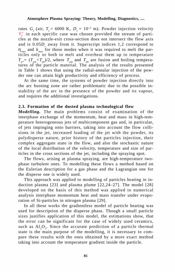
85
Atmosphere Plasma Spraying: Theory, Modelling, Diagnostics, ....
rates Gf (air, T
f = 6000 K, D
c = 10–2 m). Powder injection velocity
Vpo in each specific case was chosen provided the stream of parti-
cles at the nozzle-exit cross-section does not intersect the flow axisand is 0.05D
c away from it. Superscript indices 1,2 correspond to
ηmax
and kmax
for those modes when it was required to melt the par-ticles only or both to melt and overheat them up to temperatureT
p*= (T
pm+T
pb)/2, where T
pm and T
pb are fusion and boiling tempera-
tures of the particle material. The analysis of the results presentedin Table 1 shows that using the radial-annular injection of the pow-der one can attain high productivity and efficiency of process.
At the same time, the systems of powder injection directly intothe arc burning zone are rather problematic due to the possible in-stability of the arc in the presence of the powder and its vapour,and requires the additional investigations.
2.3. Formation of the dusted plasma technological flowModelling. The main problems consist of examination of theinterphase exchange of the momentum, heat and mass in high-tem-perature heterogeneous jets of multicomponent gas and, in particular,of jets impinging onto barriers, taking into account the flow colli-sions in the jet, increased loading of the jet with the powder, itspolydisperse nature, prior history of the particles injection, theircomplex aggregate state in the flow, and also the stochastic natureof the local distribution of the velocity, temperature and size of par-ticles in the cross sections of the jet, including the spraying spot.
The flows, arising at plasma spraying, are high-temperature two-phase turbulent ones. To modelling these flows a method based onthe Eulerian description for a gas phase and the Lagrangian one forthe disperse one is widely used.
This approach was applied to modelling of particles heating in in-duction plasma [23] and plasma plume [22,24–27]. The model [28]developed on the basis of this method was applied to numericalanalysis interphase momentum heat and mass transfer under evapo-ration of Si-particles in nitrogen plasma [29].
In all these works the gradientless model of particle heating wasused for description of the disperse phase. Though a small particlesizes justifies application of this model, the estimations show, thatthe error can be significant for the case of widely used ceramics,such as Al
2O
3. Since the accurate prediction of a particle thermal
state is the main purpose of the modelling, it is necessary to com-pare these results with the ones obtained by a more exact methodtaking into account the temperature gradient inside the particle.

86
Thermal Plasma Torches and Technologies
In this connection, it is very important to formulate a new ap-proaches for Eulerian and Lagrangian computing of the turbulentdust-laden plasma jets and their combinations with the purpose toimprove the quality and reliability of the obtained numerical results,including the accuracy of the description of complicated technologi-cal flow.
To illustrate the possibilities of such approach the comparisonwas made of the results obtained using two models of particle heat-ing in plasma. The widely used model gradientless heating was ap-plied for modelling of two-phase plasma jet temperature and velocityfields. Calculation were conducted for the jet under dense loadingconditions. The modelling of particle thermal parameters was per-formed by the method accounting for the gradient of temperature in-side particles in the previously obtained numerical velocity and tem-perature fields of the carrier gas flow, corresponding to the samedusted plasma jet [22].
In this study, the method [7] was applied for modelling the parti-cle heating which takes into account the temperature gradient insideit. This approach uses the modification of the control physical vol-ume (CFV) method to account for particle melting. The particle vol-ume is divided into spherical layers in such a way that the front ofmelting is the common boundary surface of two adjacent layers. Itis assumed that the temperature distribution inside any layer is para-bolic. Using integration over CFV, the heat conduction equation isreduced to the Cauchy problem for an ordinary differential equationssystem that determines the temporary evolution of mean temperatureinside layers. To make this system equivalent to the initial boundary-value problem, we used a procedure based on recovering paraboliccoefficients from the known mean values of temperature and conti-nuity conditions for temperature and heat flux. The procedure alsouses the boundary conditions at the particle external surface andcentre and at the melting front. Full description of the method wasgiven in [7]. The results of the paper [22] were chosen for realisa-tion of the aforesaid comparison. The mathematical model [22] in-cludes widely used (k-ε)-model of turbulence for closing equationsof carrying flow, Lagrangian Stochastic Deterministic model [30] todescribe the particle motion in the high temperature turbulent flow,Particle Source in Cell (PSI-cell) method [31] for computing parti-cle-plasma interaction. The model [7,13] was used to take into con-sideration the suppression of the turbulence energy by the dispersephase. This model does not require any new empirical constants, sothe standard values of the (k-ε)-model constants were used:

87
Atmosphere Plasma Spraying: Theory, Modelling, Diagnostics, ....
Fig.2 The diagram of flow. Fig.3 The particles distribution by size.
C C C k h1 21 1 92 0 09 1 0 1 3 0 9= = = = = =.43, . , . , . , . , . .m es s s
The geometry of the flow under consideration is shown in Fig.2.The heterogeneous flow modelled was calculated in two steps. Atfirst, the flow within the plasma torch channel was calculated. Thedistributions of velocity, temperature and turbulence energy at theinitial section were uniform in the flow region behind the area ofaxial symmetrical (diffusive) arc attachment. At the outlet from thechannel all variables had boundary conditions of the boundary layertype. The particles were introduced into the flow normally to the x-axis at the distance of 0.5D
c behind the initial section. The distribu-
tion of initial particles co-ordinates along the injector slit were as-sumed to be uniformly random, while their initial velocities had aGaussian distribution with the mean value V
p=1.64 m/s.
The temperature gradient within the particle was not taken intoaccount when the thermal state of the disperse phase was modelled,i.e. the surface temperature was assumed to be equal to the meanvolume temperature. The losses due to particle radiation were takeninto account in the heat balance of the disperse phase. The tem-perature dependence of the coefficient of emissisivity of Al
2O
3 was
approximated in accordance with data [32].The resulting profiles of variables of the carrying flow and the
particles parameters were used as boundary conditions for the cal-culation of the heterogeneous jet normally impinging on an obstacle.
The calculations were carried out using the following values ofgeometrical and regime parameters: diameter of the plasma torchnozzle – D
c = 10–2 m, its length L
c = 4×10⁻² m, the width of the in-
jector slit h = 10–3 m, spraying distance L = 0.1 m, plasma-forminggas (air) flow rate G
f = 10–3 kg/s, transport gas (air) flow rate G
tr =
10–4 kg/s, Al2O
3 particles flow rate G
p=(1÷2)×10–3 kg/s, initial tem-

88
Thermal Plasma Torches and Technologies
perature of the plasma Tf = 6000 K, initial intensity of turbulence
Ka=0.1. The thermodynamic and transport properties of air werecalculated with the help of the data tabulated in [33].
In all calculations, the temperature of the nozzle walls and theobstacle was taken as constant T
b = 600 K, the environment tem-
perature was taken equal to Tf ,
= 300 K. The particle size distribu-tion function is shown in Fig.3. For the calculations it was approxi-mated by dividing the particles into ten groups. The flow fields ob-tained are shown in Figs.4 and 5 for two loading ratios (k = G
p/
Gf = 1 for the upper half of the figures, k = 2 for the lower ones).Because the stochastic solution of this problem can be realised
only on a supercomputer, to perform comparison it was supposed,that the initial particle velocity is equal to the average starting onein the previous problem. Dynamic interaction and heat transfer be-tween plasma and particles was modelled using the (same as in[22]) empirical laws for the drag force [34] and heat transfer [35]:
Cdp
p pf p
fp
f f
f p f p
= + =
+
•
• •• •24
1 0 15 2 0 60 687 0 5 0 33
0 2
ReNu. Re , . Re Pr .
. ,
,,. . , ,
, ,
.
ll
r mr m
Here Re /p f p f p fD U U= -r m
is Reynolds number, symbol “ ”corresponds to the parameters at the so-called “film” temperatureT T Tp f= +( ) / 2 , the first subscripts ‘f’ and ‘p’ correspond to the pa-rameters of the gas flow and particles, and additional subscripts ‘∞’or ‘p’ correspond to the parameters calculated at the local gas orsurface temperature of the particles. Calculations were performedfor the same values of the particle diameters as in base modelling.
The variations of the gas temperature along the ten particle tra-jectories, corresponding to ten groups considered, are shown in
Fig.4 The isothachs of the carrier gas flow at two loading ratio; up-per and lower half of picture correspond to k = 1 and 2, accord-ingly.

89
Atmosphere Plasma Spraying: Theory, Modelling, Diagnostics, ....
Fig.6. It is seen that the large particles penetrate deeper into thehigh temperature core (initial part of trajectory is not resolved in theused scale). The sharp temperature fall due to intensive mixing atthe nozzle exit is more pronounced for the smaller particle flowrate. The temperature level is smaller for the greater particle flowrate due to intensive flow cooling by particles. The temperature his-tory of the particles is presented in Fig.7. The dark isotherm corre-sponds to the melting point of the particle material. It is necessaryto note that for the smaller loading ratio the large particles heatingis slower due to the higher velocities of the carrier flow. The in-crease of the particle melting degree along the trajectory is shownin Fig.8. These plots are in accordance with Fig.7 and also show
Fig.5 The isotherms of the carrier gas flow at two loading ratios; upper and lowerhalf of picture correspond to k = 1 and 2, accordingly
Fig.6 Variation of gas temperature along particle trajectories: a) k = 1, b) k = 2.
ba

90
Thermal Plasma Torches and Technologies
more rapid melting of the large particles for the higher loading ratio.The range of particle temperature before impact is 2300÷2700 K
for the low loading ratio and 2380÷2440 K for the higher one. Thetemperature differences between these results and those obtainedwith the use of the gradientless model are higher for the low loadingratio and are of the order of 15%.
Hence, to obtain more realistic results while modelling the high-temperature turbulent gas flow with admixtures of inertia particles,it is desirable to combine simultaneously two approaches: (i) theLagrangian stochastic deterministic model, and (ii) the Lagrangianmodelling of the representative set of single particles with accountfor their complex aggregate states in-flight.
Diagnostics. It is impossible to research and develop high-tem-perature technologies based on powder processing without local si-multaneous in-flight measuring the temperature, velocity and size ofsingle particles. During the last decade such complex apparatus has
a b
Fig.7 Variation of particles temperature along particle trajectories: a) k = 1, b) k = 2.
Fig.8 Variation of particles melting degree along trajectories: a) k = 1, b) k = 2.
a b

91
Atmosphere Plasma Spraying: Theory, Modelling, Diagnostics, ....
be realised on different laboratory levels and improved by a numberof scientific groups in Germany, France, Canada, USA, Japan andRussia.
Two approaches realising such multiparameter apparatus for dis-perse phase study and control are based on: (i) optical registrationof the light emitted by the single particle, (ii) combination of latterand some laser-optical diagnostic method (time-of-flight or LDA).
The first approach at the multiparameter measurements is moresimple and reliable. It is based on mathematical processing of thepyrometric signal, modulated by a special diaphragm (mask), corre-sponding to the flying pass single particle.
The new realisation of this approach, proposed by us in [36,37],appears to have considerable promise for the local simultaneous in-flight measuring the vector of velocity, size and surface temperatureof single particles. Figure 9 illustrates the sector multislit diaphragmplaced in the object plane of our diagnostic apparatus. This complexdiaphragm includes the following elements: 1) circular slit with ra-dius of r
0 and with centre O
1 used for starting up the two-channel
analog-digital converter (ADC) by scattered laser radiation at themoment of its intersection by the particle; 2) the narrow straight slitS
1 of width h
1, intersecting the axis Ox under angle a at the dis-
tance l1 from the point O
1; 3) the wide slit S
W, being part of the ring
Fig.9 The principal diagram of diagnostic apparatus (a), the multislit sector diaphragm(b), and calibration device used (c).
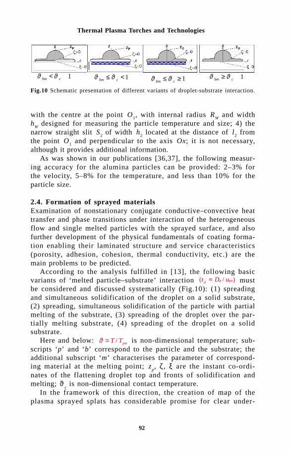
92
Thermal Plasma Torches and Technologies
with the centre at the point O1, with internal radius R
W and width
hW
designed for measuring the particle temperature and size; 4) thenarrow straight slit S
2 of width h
2 located at the distance of l
2 from
the point O1 and perpendicular to the axis Ox; it is not necessary,
although it provides additional information.As was shown in our publications [36,37], the following measur-
ing accuracy for the alumina particles can be provided: 2–3% forthe velocity, 5–8% for the temperature, and less than 10% for theparticle size.
2.4. Formation of sprayed materialsExamination of nonstationary conjugate conductive–convective heattransfer and phase transitions under interaction of the heterogeneousflow and single melted particles with the sprayed surface, and alsofurther development of the physical fundamentals of coating forma-tion enabling their laminated structure and service characteristics(porosity, adhesion, cohesion, thermal conductivity, etc.) are themain problems to be predicted.
According to the analysis fulfilled in [13], the following basicvariants of ‘melted particle–substrate’ interaction ( / )t D ud p po≈ mustbe considered and discussed systematically (Fig.10): (1) spreadingand simultaneous solidification of the droplet on a solid substrate,(2) spreading, simultaneous solidification of the particle with partialmelting of the substrate, (3) spreading of the droplet over the par-tially melting substrate, (4) spreading of the droplet on a solidsubstrate.
Here and below: ϑ = T Tpm/ is non-dimensional temperature; sub-scripts ‘p’ and ‘b’ correspond to the particle and the substrate; theadditional subscript ‘m’ characterises the parameter of correspond-ing material at the melting point; z
p, ζ , ξ are the instant co-ordi-
nates of the flattening droplet top and fronts of solidification andmelting; ϑ
c is non-dimensional contact temperature.
In the framework of this direction, the creation of map of theplasma sprayed splats has considerable promise for clear under-
ϑ ϑbm c> <1 ϑ ϑbm c> ≥1ϑ ϑbm c≤ <1 ϑ ϑbm c≤ ≥ 1
Fig.10 Schematic presentation of different variants of droplet-substrate interaction.

93
Atmosphere Plasma Spraying: Theory, Modelling, Diagnostics, ....
a b
Fig.11 The photographs of plasma jets impinging on a flat barrier at different regimesof outflowing: a - turbulent (Re=820); b - laminar (Re=580).
standing the ways of developing the new generation of plasmasprayed materials. In this connection, our last publication [12,13,38-42] can be useful at criterion generalisation, classification and inter-pretation of the experimental data obtained for the case of low vis-cosity - high thermal conductivity of melted particle material.
2.5. Post thermal treatment of sprayed materialExamination of a set of processes (heating, phase and structuraltransformations in the coating material and the substrate, etc.), ac-companying the heat treatment of plasma-sprayed materials andcoatings by the means of highly concentrated energy fluxes (electricarc, plasma jet, electron beam, laser radiation) are now in the stageof the intensive study in different scientific groups.
Among the different methods of post treatment of sprayed mate-rial the use of the laminar plasma jet is rather perspective [13-16].This method is rather simple in a realisation and effective, and, fromthe point of view of the heat density flux is comparable with an arc.Figure 11. shows the photographs of jets leaving the nozzle of theplasma torch at turbulent and laminar regime of flow out corre-sponding to two different flow rate of the plasma-forming gas(nitrogen) at the fixed distance from the outlet of the nozzle to thebarrier (8 gauges). In the second case (Fig.11,b), the density of heatflux from laminar plasma jet to the surface is of several timeshigher in comparison with turbulent one (Fig.11,a).+ "#&!&&* "% ' !)&, "'"*)

94
Thermal Plasma Torches and Technologies
For further development of high plasma technologies for materialtreatment and production under conditions of their superfast quench-ing, including interaction with solid surface, it is necessary to carryout the combined experiment [7,12], covering sequentially all thelinks of the chain, defining the formation of a stable final productwith the preset properties. These properties must be guaranteed notonly under laboratory conditions but industrial ones as well. In thefirst place, this is related to the plasma spray and surface hardeningtechnologies.
The problem-oriented core of the complex experiment in plasmaspraying is the dialogue programme complex (DPC) ‘plasma torch–dusted jet–coating’ [43,44]. This is a multipurpose, constantly pro-gressing complex of scientific, methodical, programme and informa-tion means aimed at substantial increase in the efficiency of thefundamental and technological investigations in plasma spraying andrelated technologies. The creation of such complex, incorporating incompressed form the knowledge base for appropriate subject-matterfields will be useful for establishment of the inverse link betweenthe specific practical demands of technologists and scientific labora-tories, and will stimulate the solution of some scanty investigatedproblems, providing uniform accuracy of the calculation of eitherphenomena. In this paper the brief survey of the results in theabove-mentioned field of activity is presented.
DPC ‘plasma torch–dusted jet–coating’ is a problem-orientedcomplex of programs. It is intended for various categories of users.On one hand, it should be rather simple to operate. On other hand,it should be multipurpose, since it is necessary at least for: (i) study-ing the interphase momentum, heat and mass transfer on the basisof computer experiment, (ii) joint physical and computational experi-ment, (iii) approbation and mutual comparison different physico-mathematical models and experimental data, (iv) training of special-ists engaged in the technologies of powder materials plasmaprocessing and, first of all, thermal spraying, (v) solution of specificapplied problems, including optimisation of the regime parameters.
In its turn, DPC orientation for a wide range of users and sim-plicity of its operation require a thorough consideration of the fol-lowing problems: (i) the development of simple and effective struc-ture of the programme packages, (ii) the creation of internal datastructure, providing convenience in programming of the individualsubsystems responsible for simulation of either processes included inthe scope of investigation as well as allowing their broadening, (iii)the choice and development, if necessary, of sufficiently reliable and

95
Atmosphere Plasma Spraying: Theory, Modelling, Diagnostics, ....
universal numerical methods and creation of software on their basisenabling to synthesise different schemes of computational algo-rithms, (iv) the development of input languages close to natural de-scription of the classes considered problems, (v) the provision of thepossibility to operate with different data banks, (vi) the creation ofservice modules set for representation and interpretation of the re-sults obtained, (vii) the provision of error diagnostics throughout theoperation of the complex.
One of the important requirement imposed for DPC is to providethe possibility to carry out the computational experiment using themodels with different degree of complexity and hence adequacywhile describing either processes constituting the chain of the phe-nomena. Hence, it is expedient to simultaneous developing thephysico-mathematical models and appropriate software, constitutingthe scope of DPC, in the following directions: (i) the development ofanalytical methods providing the solution of certain model problemsin the final form, (ii) obtaining the approximate analytical engineer-ing solutions, (iii) direct computational experiment using the modelwith different degree of complexity and dimensionality. A rationalcombination of these three approaches allows to promote the optimi-sation of the regime parameters of the processes as it may be im-plemented in two stages: (i) high-speed computing set of modelproblems permiting the approximate analytical or rough numericalsolution to obtain extreme estimates as well as to investigate quali-tative the behaviour of divider function and localisation of the opti-misation region, (ii)subsequent refinement of the process behaviourin the whole using the more complete models allowing to obtain adetailed information (e.g. while investigating the melt– droplet–substrate interaction, the first stage may consists of prediction ofthe contact temperature, the dynamics of the particle solidificationat its deformation on the surface, and the thickness and diameter ofsplat after solidification by using the theoretical solutions; the sec-ond stage of interest may includes the detailed information about thephase transition, the rate of supercooling in the separate particles’zones at interaction by using more complicated description of com-plex problem).
The last version of the dialogue programme complex provides: (i)engineering calculation of linear scheme plasma torches (volt-ampere characteristics (VAC), thermal efficiency, mean-mass valuesof velocity, enthalpy and temperature of plasma flow behind the an-ode arc attachment spot, etc.), (ii) simulation of powder injectioninto plasma torch nozzle behind the anode attachment arc spot (one-

96
Thermal Plasma Torches and Technologies
sided injection, radial-annular one) and calculation of gasdynamicparameters of the heterogeneous plasma flow for the nozzle exitsection, (iii) Eulerian and Lagrangian modelling (by using the differ-ent physico-mathematical descriptions) of the heterogeneous high-temperature subsonic jet (both laminar and turbulent) of complexgas composition with polydisperse particles, including the interactionwith a normally placed substrate, (iv) simulation of unsteady – stateconjugate conductive – convective heat transfer between flatteningand solidifying melted particle and substrate, (v) prediction of theregularities of sprayed material formation (lamellar structure, macro-porosity, dynamic of coating growth) dependent on the statisticaldistributions of particles velocity, temperature, aggregate state, andsize over the spraying spot.
- "& !' '" "% ,& !&#'4.1. Plasma spraying in preparation of metal supported catalystsThe development of new environmentally clean and energy safetechnologies is one of today’s important tasks. Examples are gasand oil processing, motor fuel production, purification of wastewatercontaining organic compounds, etc. Catalysts to be used in theseprocesses must possess high thermal stability and wear resistanceproperties.
Application of metal substrates as catalyst supports is becomingmore common. Metals have some advantages that make their appli-cation in catalysis more attractive than ceramic supports. Their ad-vantages include a high mechanical strength and heat conductivitycharacteristics. Protection of catalytic coatings against mechanicalshock and chemical exposure to the reaction medium and the con-servation of the catalytic activity at high temperatures are the mainproblems when metal-supported catalysts are used. The preparationof materials with strong contact between the catalytic layer and themetal surface at high temperatures is also a complicated problem.
Plasma spray of washcoatings of alumina, titania, zirconia, etc.will allow one to solve successfully the problem of the adhesion ofthe active component to the metal surface and to protect the metalsupport substrates from aggressive medium and improve their dura-bility for high temperature use. Moreover, the plasma spray methodwill give an opportunity to design composite materials consisting ofdifferent combinations of plasma-sprayed catalytic and protectivelayers.
It is important to note that there are no strict limitations on thegeometry of granulated or monolithic supports when plasma spray

97
Atmosphere Plasma Spraying: Theory, Modelling, Diagnostics, ....
methods are used. Both substrates of simple geometry (flat sur-faces) and complex substrates (foam materials and honeycombmonoliths) can be applied successfully.
Although plasma spray techniques are well developed and incommon use today, information on the application of these methodsin catalysis is rather scarce. Traditionally, plasma spraying is appliedwhen the formation of dense, non-porous protective layers is neces-sary and this makes the direct use of this method in catalysis rathercomplicated.
Our publications [45,46] are devoted to application of above-men-tioned DC plasma torch for atmosphere plasma spraying of thealumina coatings under different regimes of the jet outflow (laminar,transient or turbulent) on the metal substrates of differentgeometries (plates, foams) for subsequent synthesis of perovskitecatalysts.
The properties of the catalysts (Fig.12), developed with the useof coating sprayed under laminar regime of plasma jet outflow, werecompared with those of catalysts having the same phase compositionand BET surface area but synthesized without the use of theplasma-sprayed alumina layer. The catalysts calcined at tempera-tures from 600 to 1000 °C demonstrated the same level of activityas catalysts synthesized using the plasma technique. A difference inthe activity between these types of catalysts appeared when the du-ration of calcination at 1000 °C was increased from 3 to 9 hours.There was no decrease in the activity of the catalyst with a plasma-sprayed alumina layer whereas the temperature to give 50% conver-sion rose from 600 to 655 °C for the catalyst prepared without aplasma-sprayed layer (Fig.13). It appeared that a plasma-sprayedwashcoating layer consisting of alumina on a Ni foam support pre-vented the nickel from becoming oxidized more successfully and in-creased the thermal stability of the catalyst.
4.2. Piston of diesel engine with a thermal barrier coatingZirconia stabilised by yttria powder coating [47], sprayed on a pistonhead by the use of the developed plasma torch providing the laminarplasma jet outflow (Fig.14), possesses an improved service charac-teristics (adhesion, cohesion, porosity). The coating produced per-mits: (i) completely eliminate the burnout of the piston head, (ii) todecrease the operating temperature near the piston ring grooves, re-sulting in an increase service time of the piston, (iii) to increase thecombustion temperature of fuel mixture, resulting in an increase theefficiency of combustion process and ecological characteristics of

98
Thermal Plasma Torches and Technologies
Fig.12 Micrograph of a cross section view of a catalyst consisting of La–Co on a Nifoam support.Fig.13 Temperature dependencies of methane conversion (1% CH4 in air) on catalysts,V = 400 h–1: 1 - 10% LaCoO3Ni, plasm., T = 1000°C, 3 h; 2 - 10% LaCoO3/Ni, chem.,T = 1000°C, 3 h; 3 - 10% LaCoO3/Ni, plasm., T=1000°C, 15 h; 4 - 10% LaCoO3/Ni,chem., T = 1000°C, 15 h.
diesel, (iv) to increase the economic feasibility of diesel no less than5%, and (v) to increase the diesel engine service time as a wholeno less than 20%.
. " '#" In the review, the author has attempted to analyze the current stateof the thermophysics of plasma spraying, mainly in the context ofproblems examined in the last decade in the Laboratory of PlasmaDynamics of Disperse Systems of the Institute of Thermophysics(and now of the Institute of Theoretical and Applied Mechanics) ofSiberian Division of the Russian Academy of Sciences.
The individual problems, arising during explanation, were dis-cussed. The solution of these problems is of considerable impor-tance for the efficient understanding of the physical processes form-ing the basis of the ‘plasma torch–powder material injection–dustedplasma jet formation–formation of the coating of single particles -its subsequent heat treatment’ chain.
The obtained results of investigations have allowed us to createthe first version of the dialogue programme complex ‘plasma torch–dusted plasma jet–coating’ for direct computational experiment inplasma spray technology. The creation and further development ofsuch problem-oriented software incorporating in compressed formthe knowledge and data banks will be useful by far not only for fun-damental investigations but for the technological applications aswell. We hope that it will be also useful for more close the feed-
99
Atmosphere Plasma Spraying: Theory, Modelling, Diagnostics, ....
back between the technological groups and research laboratories.For more rapid further development and extension of its possibilities,in our opinion, it is essential to establish closer co-operationbetween different scientific groups, because plasma spraying ismultidiscipline technology. It is obviously that there are a lot ofcommon points between the plasma spray technology and other ther-mal spray technologies, therefore from ideological and scientificpoints of view this paper may be useful also for another branches ofthermal spray technology.
References1 N.N.Rykalin, et al., In: Plasma Processes in the Metallurgy and in the
Technology of Nonorganic Materials (in Russian), Nauka, Moscow (1973),p.66.
2 D.Apelian, et al, International Metals Review, 28, No.5, 271 (1983).3 N.El-Kaddah, et al, Metallurgical Transactions B., 15B, No.59 (1984).4 E.Pfender, Pure and Appl. Chem., 60, No.5, 591 (1988).5 M.Ushio, Proc. of Jap. Symp. on Plasma Chem. Vol.1, (1988), p.187.6 T.Yoshida, Materials Trans. JIM, 31, No.1, 1 (1990).7 M.F.Zhukov and O.P.Solonenko, High-Temperature Dusted Jets in the
Powder Materials Processing (in Russian), Institute of ThermophysicsNovosibirsk, (1990).
8 D.Steffens and M.Mack, Pure and Appl. Chem., 62, No.9, 1801 (1990).9 R.W.Smith and R.Novak, Intern. J. of Powder Metallurgy, 23, No.4, 231
(1991).1 0 J.Szekely and R.C.Westhoff, In: Thermal Plasma Applications in Ma-
terials and Metallurgical Processing, Vol.55, N.El-Kaddah (ed), The Min-erals, Metals & Materials Society (1992).
11 P.Fauchais and M.Vardelle, Pure and Appl. Chem., 66, No.6, 1247 (1994).1 2 O.P.Solonenko, Pure and Appl. Chem., 62, No.9, 1783 (1990).1 3 O.P.Solonenko, In: Thermal Plasma and New Materials Technology, Vol.2,
p.7, O.P.Solonenko and M.F.Zhukov (eds), Cambridge Interscience Pub-lishing, England (1995).
1 4 V.I.Kuz’min, et al, Proc. of the 3rd European Congress on Thermal PlasmaProcesses (1995), p.405.
1 5 V.I.Kuz’min, et al, Proc. of the 14th Int. Thermal Spray Conf., Kobe, Japan(1995), p.1091.
1 6 V.I.Kuz’min, et al, Proc. of the 8th National Thermal Spray Conf., Houston,USA, (1995), p.264.
1 7 V.E.Ovcharenko, et al., In: VDI-Gesellschaft Werkstofftechnik, 3rd Europ.Congress on Thermal Plasma Processes, VDI-Verl., Dusseldorf (1995),p.395.
1 8 V.E.Ovcharenko and O.P.Solonenko, Proc. of the 14th Int. Thermal SprayConf., Kobe, Japan (1995), p.1151.
1 9 V.E.Ovcharenko, et al, Proc. of 4th European Conf. on Thermal PlasmaProcesses, Athens, Greece (1996).
2 0 O.P.Solonenko and A.L.Sorokin, In: Plasma Jets in the Developmentof New Materials Technology, O.P.Solonenko and A.I.Fedorchenko (eds),VSP Publishing, Utrecht (1990), p.243.

100
Thermal Plasma Torches and Technologies
2 1 O.P.Solonenko and A.L.Sorokin, Izvestiya SO AN SSSR, Ser. Techni-cal Sci. (in Russian), 4, 73 (1990).
2 2 O.P.Solonenko and A.L.Sorokin, In: VDI-Gesellschaft Werkstofftechnik,3rd Europ. Congress on Thermal Plasma Processes, VDI-Verl., Dusseldorf(1995), p.129.
2 3 P.Proulx, et al, Int. J. Heat Mass Transfer, 28, No.7, 1327 (1985).2 4 P.Proulx., et al, Proc. of the 8th Intern. Symp. on Plasma Chem., 13
(1987).2 5 A.Vardelle, et al, Proc. of the 7th Intern. Symp. on Plasma Chem., 898
(1985).2 6 C.H.Chang and J.D.Ramshaw, Proc. of the 10th Intern. Symp. on Plasma
Chem., 4, No.1,1-6 (1991).2 7 O.P.Solonenko and A.L.Sorokin, Proc. of the 10th Intern. Symp. on Plasma
Chem.,1, No.1, 1-2 1 (1991)2 8 G.S. Pavlovic, et al, J. of High Temperature Chemical Processes, Suppl.,
1, No.3, 381 (1992).2 9 P.Stefonovic, et al, Numerical analysis of heat transfer between nitrogen
plasma and injected Si particles in axisymmetric reactor (in print).3 0 D.Milojevic, Proc of the 2nd Workshop on Two-Phase Flow Prediction,
Erlangen, Germany, 31 (1985).3 1 C.T.Crowe, et al, Trans. of ASME, J. Fluids Engineering, 325 (1977).3 2 M.Vardelle, Cycle Thesis. Univ. of Limoges, France (1980).3 3 N.B.Vargaftik, Tables of the Thermophysical Properties of Liquids and
Gases, 2nd ed., Hemisphere, Washington D.C. (1975).3 4 D.J.Carlson and R.F.Hoglund, AIAA Journal, 2, No.1 (1964).3 5 I.V.Kalganova and V.S.Klubnikin, J. of High Temperature (in Russian),
14, 408 (1976).3 6 A.A.Mihalchenko, et al, Proc. of the 8th National Thermal Spray Conf.,
Houston, USA (1995), p.741.3 7 O.P.Solonenko, et al, Proc. of 3th Asia-Pacific Conf. on Plasma Sci-
ence and Technology, Tokyo, Japan (1996), p.241.3 8 O.P.Solonenko, et al, Proc. of the 14th Int. Thermal Spray Conf., Kobe,
Japan (1995), p.359.3 9 O.P.Solonenko and A.V.Smirnov, Proc. of 12th Int. Symp. on Plasma Chem-
istry, Minneapolis, USA (1995), p.874.4 0 O.P.Solonenko, Proc. of the 8th National Thermal Spray Conf., Houston,
USA (1995), p.423.4 1 O.P.Solonenko and A.V.Smirnov, Proc. of 3th Asia-Pacific Conf. on Plasma
Science and Technology, Tokyo, Japan (1996), p.247.4 2 O.P.Solonenko, In: Werkstofftechnologie auf dem Weg in das Jahrhundert:
Vortrage und Veroffentlichungen des gleichnamigen 15. DortmunderHochschulkolloquiums (1996), Dortmund/ Lehrstuhl furWerkstofftechnologie, Universitat Dortmund.-Aachen, Mainz (1996).
4 3 O.P.Solonenko, In: High-Temperature Dust-Laden Jets in Plasma Tech-nology, O.P.Solonenko and A.I.Fedorchenko (eds), VSP Publishing House,Utrecht, Netherlands (1990), p.59.
4 4 O.P.Solonenko, et al, Proc. of 6th National Thermal Spray Conf., Anaheim,USA (1993).
4 5 Z.R.Ismagilov, et al., Proc. of 13th Intern. Symp. on Plasma Chemis-try, Beijing, China (1997).
4 6 O.Yu.Pogyacheva, et al., In: Application of plasma spraying in prepa-

101
Atmosphere Plasma Spraying: Theory, Modelling, Diagnostics, ....
ration of metal supported catalysts, Catalysis Today (in print), (1998).4 7 O.P.Solonenko, et al, Proc. of 5th Intern. Conf. “Film and Coatings”,
Saint-Peterburgh, Russia (1998).

102
Thermal Plasma Torches and Technologies
V.A. NeronovInstitute of Theoretical and Applied Mechanics, Siberian Branch, Russian Academyof Sciences, 4/1 Institutskaya Str., Novosibirsk, 630090, Russia
The basis of scientific-technical progress is power engineering,automatization, and materials. Traditional materials cannot satisfycomplex demands of high temperatures, velocities, loadings, andaggressive media. It leads to elaboration of new high-temperaturematerials on the basis of refractory compounds – borides, carbides,nitrides, silicides, and their compounds. On the basis of refractorycompounds, traditional materials are made considerably better; high-effective materials of atomic power engineering, of electrotechnicalintention are manufactured, as well as instrumental, fire-proof,space, structural, and other materials. One of the main directions ofpresent-day material studies is the elaboration of principles ofdesigning materials (including coatings) with a highly dispersedstructure. Plasma chemical synthesis of ultra-fine powders is ofprimary importance in this matter.
Materials occupy a special place in this triad since the develop-ment of power engineering and automatization depends on the levelof materials.
Today’s development of materials follows seven research direc-tions shown in Fig. 1. They are ceramic, composite, polymer, vit-reous, and ultra-pure (10–7–10–10 % of impurities) materials, coat-ings and new metallic materials being considered as individual ac-tivities.
These seven research directions can be complemented by anotherone: diagnostics and material quality control.
Traditional materials cannot satisfy complex demands of hightemperatures, velocities, loadings, and aggressive media. The capa-bilities of traditional quasi-equilibrium processes have been ex-hausted for further improvement of technology. Extreme values of
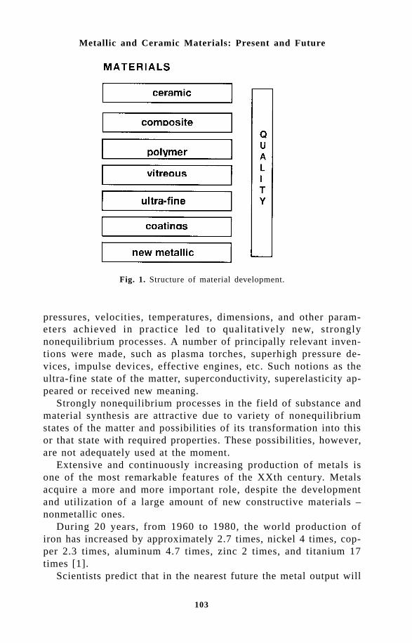
103
Metallic and Ceramic Materials: Present and Future
Fig. 1. Structure of material development.
pressures, velocities, temperatures, dimensions, and other param-eters achieved in practice led to qualitatively new, stronglynonequilibrium processes. A number of principally relevant inven-tions were made, such as plasma torches, superhigh pressure de-vices, impulse devices, effective engines, etc. Such notions as theultra-fine state of the matter, superconductivity, superelasticity ap-peared or received new meaning.
Strongly nonequilibrium processes in the field of substance andmaterial synthesis are attractive due to variety of nonequilibriumstates of the matter and possibilities of its transformation into thisor that state with required properties. These possibilities, however,are not adequately used at the moment.
Extensive and continuously increasing production of metals isone of the most remarkable features of the XXth century. Metalsacquire a more and more important role, despite the developmentand utilization of a large amount of new constructive materials –nonmetallic ones.
During 20 years, from 1960 to 1980, the world production ofiron has increased by approximately 2.7 times, nickel 4 times, cop-per 2.3 times, aluminum 4.7 times, zinc 2 times, and titanium 17times [1].
Scientists predict that in the nearest future the metal output will

104
Thermal Plasma Torches and Technologies
be increasing. Assuming that the mean yearly consumption of steel,for example, approaches the level of developed countries (500 kgper capita), then about 2.5–3.0 billion tons of steel should be pro-duced on the Earth every year. Taking the metal output of 1960 forunity (note that this value has been achieved at least during 4–5millennia), the above idea can be illustrated by the following plot(Fig. 2). We can see that in the accepted scale, the steel outputcurve at the end of the second millennium goes vertically upwards,like a rocket. The rate is impressive, is not it? Moreover, it is tre-mendous! What does the production of these vast amounts of metalmean?
Let us consider several examples. For yearly production of castiron in the Soviet Union in early 80s, the iron ore transportationrequired a train that could encircle the Earth equator seven times[1]. Three more circles, and this will be equal to the distance to theMoon. Cosmic scales on the Earth!
In 1975, the ferrous metallurgy of the Soviet Union burnt theamount of fuel equivalent to the biannual output of coal in GreatBritain, a traditionally coal-mining country. A tremendous consump-tion of water and energy!
Nonferrous metallurgy requires even higher consumption per tonof metal.
In 1986, the stationary sources, automobiles, agricultural andmilitary facilities, air, naval, and railway transport of the USSRproduced 350 kg of hazardous waste per capita, which means thateach Soviet citizen got a kilogram of ‘waste’ every day.
In 1990, each Soviet citizen already got 450 kg of waste per
Fig. 2. Dynamics of normalized metal output.
105
Metallic and Ceramic Materials: Present and Future
year. This is an average, doctored figure. A particularly hard situ-ation was observed at that time in 43 cities of Russia. The leaderin this list was Norilsk. Only the stationary sources of this cityproduced yearly about 13 tons of waste per one Norilsk inhabitant[2]. The situation with water basins is not less catastrophic.
The above examples are sufficient to repeat the famous sayingthat the humankind rushes at full speed towards the edge of anabyss. The definition of scientific-technical progress presented atthe beginning of this paper (power engineering, automatization, ma-terials) is, therefore, incomplete and one-sided. Ecology must be theprimary reason to be taken into account.
A question arises here: what should we do next? Should we in-crease the production or is there a rational alternative? The re-searchers say there is one: improvement of the quality of materialsand the most rational use of properties imparted by nature. Forexample, the theoretical strength of metals is higher than practicallyachieved results by a factor of 10–100.
Considerable progress has been made in this direction. Let uscome back to examples. In laboratory tests of copper wire 1.25microns in diameter, a strength of 294 kgf/mm2 was obtained in-stead of 25 kgf/mm2 for technical copper. The strength of a thin ironwire 1.6 microns in diameter was 1310 kgf/mm2 instead of 30–40kgf/mm2 typical of commonly used steel [1]. Thus, the strength in-creased 30–40 times. In the ideal case, this means a 30–40foldeconomy of metal. Fibrous materials are used in practice but not yetsufficiently.
There is another example of a material that was obtained in ex-treme conditions but is frequently used now. We speak about theresearch performed at the All-Union Institute of Light Alloys(AILA) under the guidance of Academician A.Belov [1].
The traditional method of obtaining the major part of metallicsemifinished items includes metal melting, melt crystallization intoan ingot, and pressure treatment for the ingot to acquire a neces-sary shape. The weak link in this chain is crystallization.
The process of crystallization includes the changes in the chemi-cal composition of the melt, redistribution of elements and admix-tures segregation. In particularly adverse conditions of the forma-tion of large ingots, the level of segregation can reach 300 % forcarbon, 600 % for phosphorus, 1000 % for sulphur [3, p.502]. Thismeans that different sorts of metal, up to complete spoilage, are ob-tained in different parts of the ingot. Besides, the growth of grainsoccurs during crystallization, which impairs the metal properties.

106
Thermal Plasma Torches and Technologies
a b
cd
Fig. 3. b Structure of granules (a-c) and ingot (d) obtained from the same nickelalloy with cooling rates of 10000 and 4°C/s, respectively [1].
Obviously, the increasing of the crystallization rate is an effectivemethod for improvement of the metal structure and properties. Theusual rate of surface cooling of a solidifying ingot is about 1 de-gree per second. Tremendous cooling rates have been achieved atthe AILA. about a million degrees per second. This superhigh cool-ing rate could be achieved for small ‘ingots’ that are granules 5–500 microns in diameter (they are commonly obtained by sprayinga metal melt by a jet of pure neutral gas or by liquid metal spray-ing due to centrifugal forces).
Figure 3 shows the structure of an ingot cast by the traditional
107
Metallic and Ceramic Materials: Present and Future
method and the structure of granules obtained with a cooling rateof 10000 °C/s. A drastic change in the metal structure is seen. Thegrain size decreases by a factor of 1000 and more, which is equiva-lent to the formation of a billion of grains and more instead of onegrain. Besides, the material obtained is uniform.
The technology of preparing articles from granules (granularmetallurgy) includes the following basic stages: magnetic separationand activation of granules, their separation into fractions, degassingand capsule welding-up into a container, treatment at a temperatureof about 1200 °C and pressure of about 2000 atm, thermal treat-ment of articles, mechanical treatment, and quality control. The useof the new technology increased the high-temperature strength of en-gine disks made of nickel alloys by more than 1.5 times.
Granular metallurgy has great prospects. The treatment of castarticles at high temperatures and pressures has a special signifi-cance. For example, the treatment of cast turbine blades decreasedthe spoilage percentage from 25–30 % to 0–5 %, simultaneously in-creasing the service life 2–2.5 times. Note that a complex-construc-tion blade costs roughly as much as a car [1].
The development of metallic materials will make use of techni-cal achievements of advanced technology. This means the creationof strongly nonequilibrium structures. New metallic materials arecool-resistant steels (elimination of adverse admixtures, doping),radiation-resistant steels in atomic power engineering, steels withhigh content of nitrogen (ten-fold supersaturation), alloys withamorphous and microcrystalline structure (1.5-fold increase of ul-timate strength), constructive materials made of ultrafine powders(which also leads to better mechanical characteristics), high-tem-perature steels, aluminum alloys with high strength and low density(Al–Li alloys), alloys with shape memory, etc.
Only 0.0015 % of multi-species alloys containing more thanthree components were studied in mid-80s, but the specialists pre-dict that by 2000 the number of complex alloys will significantlyincrease and amount to 250 000. Almost all metals of the periodicsystem will be used in practice [4].
Great importance in the development of new metallic materialswill belong to oxygen-free refractory compounds: carbides, nitrides,borides, silicides, etc., especially in the ultra-fine state – the regionwhere plasma chemistry will obviously play a positive role.
Refractory oxygen-free compounds are widely used due to avaluable complex of their properties: they have a high melting tem-perature (up to 4000 °C, tantalum and hafnium carbides) and a high

108
Thermal Plasma Torches and Technologies
strength approaching that of the hardest material, diamond (cubicboron nitride, etc.), they are extremely stable in metal melts (tita-nium and zirconium diborides, boron, aluminum and silicon ni-trides), they are not destroyed in the air when heated up to 1700 °C(molybdenum, tungsten, rhenium disilicides, silicon carbide) andweakly evaporate in vacuum (niobium and hafnium carbides), theyhave unique atomic physical properties (boron, uranium, thoriumcarbides) and low electric conductivity (boron nitride), they arehigh-temperature semiconductors (boron and silicon carbides). Re-
Objectives Material characteristics, examples of its usage
Refractory materials
High resistance to melted materials, erosion resistance, heat resistance. Vacuum metal spraying: metal coatings on ceramics, metals, glasses, plastics, fabrics, and leather. Calorizing of glasses instead of silvering in mirror industry, calorizing of black plate (instead of tin-plate) in food-canning industry. Protective coatings for thermocouples for controlling the temperature of steel, cast iron, and other alloys. Materials: TiB2, TiC, TiN, BN, AlN, SiC, MoSi2, etc.
Electrotechnical materials
High-temperature furnace heaters up to 1650 °C (SiC, MoSi2). Heaters for burners with neutral media up to 2800 °C (NbC). Single crystal growing, thermal treatment of specific alloys.
Materials with special electrophysical properties
Good thermoelectric properties, high heat resistance. Thermoelectrodes of high-temperature thermocouples. Thermocouples with MoSi2/WSi2 thermoelectrodes in oxidizing media (high stability, sensitivity of 10 µV/deg, measurements of temperature of melted glass, oxidizing gas media in chamber and reverberatory furnaces). Thermocouples with C/ZrB2, C/TiC thermoelectrodes in neutral and carbonizing media (high stability, sensitivity of 65 µV/deg, linear dependence in the range of 600−2500 °C). Thermoelectrodes of high-temperature thermogenerators, cathodes of powerful electronic devices for melting of refractory highly pure metals and alloys, growing and purification of single crystals, etc. Electrodes of MHD-generators, reusable electrodes for resistance welding of carbon steel, stainless steel, etc. Materials: Si3N4, MoSi2, SiC, complex carbides Zr2WC, TaWC, TaMoC, NbWC, NbMoC, etc.
Constructive materials
Hard alloys for pumping aggressive media and pulps, compressing high-temperature gases. Articles of silicon carbide: nozzles and vanes in sprayers for superphosphate drying. Hydrocyclone bodies, jet mill lining, etc.
Instrument materials
High hardness, strength, wear and chemical resistance. Abrasive and blade instruments on the basis of tungsten carbide (hardness of up to 92 HRA, elasticity modulus of up to 70000 kgf/mm2, compressive strength of 600 kgf/mm2, impact strength of up to 0.6 kgm/cm2) and tungsten-free hard alloys on the basis of titanium carbide, complex titanium-niobium carbide, titanium carbonitride, TiB2, ZrB2, TiC-TiB2, TiN-AlN. Carbide and nitride coatings increase the resistance of cutting and hard-alloy instruments by 2−5 times.
The use of refractory compounds [5,6]

109
Metallic and Ceramic Materials: Present and Future
fractory compounds are used in metallurgy, space technology, andother important areas [5].
The materials based on refractory compounds and their applica-tion are briefly presented in the table bellow.
Special attention should be paid to a cutting superhard materialon the basis of boron nitride – hexanite-R characterized by a highcutting capability, high resistance to strong shock loads. This amaz-ing result cannot be currently explained by any existing physicaltheory. Propulsion! Ceramic armor! Fabulous prospects of ceramics!Indeed, the further the experiment is from the theory, the closer itis to the Nobel Prize! Ceramics is the thing that the humankindstarted to master. Modern ceramics is the ceramics on a new heli-cal turn. In fact, a kind of ‘ceramic’ material study has appeared.
The main problem (it refers both to metallic and ceramic mate-rials) is the obtaining of materials in an ultra-fine state in order tocombine strength and plasticity. The most important scientific direc-
Fig. 4. Scheme of research activity. Bold line – our developments, thin lines - jointresearch with other organisations, double lines - research activity without our participation

110
Thermal Plasma Torches and Technologies
tion in the field of material study is, therefore, the study of com-plex equilibrium and nonequilibrium states, and construction of dia-grams of state.
The strategy of material development is to find and preserve theoptimum ratio between the fraction of traditional materials, thefraction of materials of the nearest future, and the fraction of prom-ising materials. the fraction of the latter should be at least 10-15 %, as evaluated by specialists.
The studies that we conducted in the field of borides formedtheoretical and practical grounds for subsequent works in scientificcenters of the former Soviet Union and Europe. This involved thetraining of qualified staff and creation of new materials with a valu-able complex of properties, mainly on the basis of aluminumdodecaboride (Fig. 4):
– monocrystals;– polycrystals;– superhard materials for instruments, with high resistance and
three-fold cutting capability as compared with alloys on the basisof tungsten carbide (in treatment of hard graphites);
– hard materials with characteristics at the world level;– coatings of special purpose with an economic effect of 50–60
thousand US dollars for one article, wear-resistant coatings;– thermoelectric materials with record-breaking characteristics at
1750 K that have not been surpassed yet (the priority of these re-sults has been noted abroad).
Thus, the performed work laid the basis for a promising scien-tific-technical direction in the field of borides.
We have analyzed the state-of-the-art of boride research as awhole and described it in a number of monographs (e.g., [7, 8]).Our investigations in the field of physics, chemistry, and technol-ogy of refractory compounds favored the development of a princi-pally new scientific direction of advanced material study ‘Synthe-sis, investigation and utilization of fine-grained systems in the studyof composite materials’ at the Siberian State Mining-MetallurgicalAcademy (Novokuznetsk, Prof. G.V.Galevsky). Ultrafine boridesand other compounds were used for the first time in domestic prac-tice.
A titanic contribution to material study, including refractorycompounds, was made by our famous scientist Grigory Samsonov,a corresponding member of the Ukranian Academy of Sciences. Hebrought up a lot of scientists – 200 candidates of sciences, 15 doc-tors of sciences, developed together with his followers 500 new sub-
111
Metallic and Ceramic Materials: Present and Future
stances, put into practice 150 technologies, wrote 40 monographsand 2000 articles. He did it during a short time. As it always hap-pens, envious people stood in his way. He died when he was 57, inthe prime of his life. He was in combat at the WW II. He foundeda scientific school recognized in his lifetime by the entire world. Helives with us and will live for a long time because a person is aliveas long as somebody remembers about him. These are his words,but he did not speak about himself, he spoke about those who dotheir best to serve the Motherland and the Humankind in a spirit ofhigh responsibility. He was such a person. We should know andremember it. Another such person – we must say this because wecelebrate his jubilee – is Mikhail Zhukov who, keeping up with thetime and ahead of it, made a great contribution to organization,science and practice in the field of plasma dynamics and relatedareas.
References1. A.Belov, Metal: improvement of quality ¾ the way to economy, Nauka
i Zhizn’ (Science and Life), 1982, No. 2, P.2-9.2. Argumenty i Fakty (Arguments and Facts), 1990, No. 34, P.7.3. E.V.Abrosimov, I.I.Ansheles, V.A.Kudrin, Yu.V.Kryakovsky, V.N.Orlov,
Steel Metallurgy, Metallurgiya, Moscow, 1961, 680 p.4. H.Waschull, Praparative Metallographie, VEB Duetscher Verlag fur
Grundstoffindustrie, Leipzig, 1984.5. P.S.Kisly, Obtaining articles made of refractory compounds by means
of powder metallurgy, Zhurnal Vsesoyuznogo Khimicheskogo Obshchestvaim. D.I.Mendeleeva (Journal of All-Union Mendeleev’s Chemical So-ciety), 1979, Vol. 24, No. 3, P.270-275.
6. Properties, synthesis and application of refractory compounds, Ref-erence Book, T.Ya.Kosolapova (ed.), Metallurgiya, Moscow, 1986, 928p.
7. G.V.Samsonov, T.I.Serebryakova, V.A.Neronov, Borides, Atomizdat, Moscow,1975, 376 p.
8. T.I.Serebryakova, V.A.Neronov, P.D.Peshev, High-Temperature Borides,Metallurgy, Chelyabinsk, 1991, 368 p.

112
Thermal Plasma Torches and Technologies
Volokitin G.G., Borzykh V.E. and Skripnikova N.K.Tomsk State Architectural-Building University, Tomsk, Russia
Recently, there has been a marked tendency to use non-traditionaltechnologies for the material production and waste utilization ofdifferent origin. It is very important because the possibility ofquasidisbalanced processes for the further improvement of existingtechnologies appeared to be exhausted. The value of disbalancedprocesses in the field of synthesis and obtaining new materials as wellas utilization of vital activity waste of persons is concluded in varieddisbalanced conditions of material and possibilities of it leading to oneor another condition with technology- useful characteristics. The localconcentration of energy is necessary for the realization of disbalancedprocesses. The latest knowledge on disbalanced processes has allowedthe application of the most up-to-date technologies in the field ofmaterial study and ecology, such as plasma, pulsed and high pressure.
Using the energy of plasma flows in industry has allowed us tomodify old and develop new technologies. In particular, this concernsmachine building and chemical industry. Building industry and ecologyhas been on the side from these tendencies, however here shifts aremarked, which are the most significant in the production of buildingmaterials and utilization of different type of waste.
Operated and controlled plasma heating allows us to obtain an ef-ficient mode of the technological process, ensuring the maximum use-ful output under minimum specific expenses of material and energy.Besides, high-temperature heating plasma by flows creates conditionsof strong disbalance, when high-energy particles participate under themoderate middle-mass temperature in the working process. Newknowledge of these processes has allowed the group of authors tocreate a number of new technologies in the field of building industry.These technologies have gained a new base in applied sciences, such
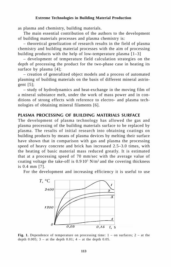
113
Extreme Technologies in Building Material Production
as plasma and chemistry, building materials.The main essential contribution of the authors to the development
of building materials processes and plasma chemistry is:– theoretical genelization of research results in the field of plasma
chemistry and building material processes with the aim of processingbuilding products with the help of low-temperature plasma [1–3]
– development of temperature field calculation strategies on thedepth of processing the product for the two-phase case in heating itssurface by plasma [4];
– creation of generalized object models and a process of automatedplasming of building materials on the basis of different mineral astrin-gent [5];
– study of hydrodynamics and heat-exchange in the moving film ofa mineral substance melt, under the work of mass power and in con-ditions of strong effects with reference to electro- and plasma tech-nologies of obtaining mineral filaments [6].
!" ! The development of plasma technology has allowed the gas andplasma processing of the building materials surface to be replaced byplasma. The results of initial research into obtaining coatings onbuilding products by means of plasma devices by melting their surfacehave shown that in comparison with gas and plasma the processingspeed of heavy concrete and brick has increased 2.5–3.0 times, withthe heating of basic material mass reduced greatly. It is estimatedthat at a processing speed of 70 mm/sec with the average value ofcoating voltage the take-off is 0.9.105 N/m2 and the covering thicknessis 0.4 mm [7].
For the development and increasing efficiency it is useful to use
Fig. 1. Dependence of temperature on processing time: 1 – on surfaces; 2 – at thedepth 0.005; 3 – at the depth 0.01; 4 – at the depth 0.05.
T, °C
t, s

114
Thermal Plasma Torches and Technologies
thermal processing principal criteria of the optimal regime: technologi-cal compatibility of plasma processing with the process of buildingproducts; the final product reliability and processing productivity, notreducing main processing, which in turn are connected with heatingand physical and chemical processes, running under the influence ofplasma on building materials at the moment of creation of glass typecoverings on their surface.
In spite of the fact that a number of works [8,9] have been de-voted to the interaction of plasma with hard substances, there is noinformation on the determination of temperature fields in the sectionof building products processed by low-temperature plasma under dif-ferent power plasma device data that is extremely important for study-ing physical and chemical conversions which take place in the prod-uct under the heat influence, which are responsible for adhesive tough-ness, chemical stability, water absorbtion, and frost resistance.
Earlier in work [10] a simplified strategy of temperature field cal-culations while heating the surface by a plasma flow was proposed;however the processes occuring on the product surface, leading to thenew phase (evaporation, formation, melting) appearance under whichheat and physical factors λ , c, a and others are changed, were nottaken into consideration. To achieve reliable results of sharing tem-perature fields, the univariate Stephan task for two-phase case wassolved. Numerical realization of the model under real significant ini-tial data was carried out by the difference method on the tacitscheme.
The results of calculations have been confirmed by experiments(Fig. 1) and were then used in physical and chemical conversions oc-curring in silicate products under the action of true temperatures.
Silicate product durability and, accordingly, under plasma process-ing – adhesive durability of covering, are determinated by the pres-ence of fundamental calcium hydrosilicates such as tobermorite andcsonotolite, which firmly connect particle grains. However, accordingto [12], in the temperature range 973–1143 K the above mentionedhydrosilicates change to β-calcium silicate (wollastonite), changing un-der 1398 K into α-modification (pseudowollastonite) with lower dura-bility. The analysis of the results shows that adhesive durability de-pends not only on the depth of the destructive layer but also on otherfactors, one of which is the granulometric filling.
Having taking as a basis the idea of ‘anchor’ fastening of glasscovering with the product base, the authors of this article have pro-posed a generalised process model of the shaping of glass coatings onbuilding products, based on the principle of ensuring reliable connec-
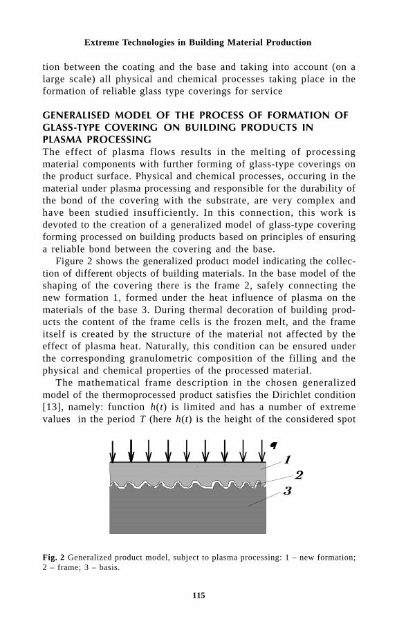
115
Extreme Technologies in Building Material Production
tion between the coating and the base and taking into account (on alarge scale) all physical and chemical processes taking place in theformation of reliable glass type coverings for service
"" # $% & !" "! The effect of plasma flows results in the melting of processingmaterial components with further forming of glass-type coverings onthe product surface. Physical and chemical processes, occuring in thematerial under plasma processing and responsible for the durability ofthe bond of the covering with the substrate, are very complex andhave been studied insufficiently. In this connection, this work isdevoted to the creation of a generalized model of glass-type coveringforming processed on building products based on principles of ensuringa reliable bond between the covering and the base.
Figure 2 shows the generalized product model indicating the collec-tion of different objects of building materials. In the base model of theshaping of the covering there is the frame 2, safely connecting thenew formation 1, formed under the heat influence of plasma on thematerials of the base 3. During thermal decoration of building prod-ucts the content of the frame cells is the frozen melt, and the frameitself is created by the structure of the material not affected by theeffect of plasma heat. Naturally, this condition can be ensured underthe corresponding granulometric composition of the filling and thephysical and chemical properties of the processed material.
The mathematical frame description in the chosen generalizedmodel of the thermoprocessed product satisfies the Dirichlet condition[13], namely: function h(t) is limited and has a number of extremevalues in the period T (here h(t) is the height of the considered spot
Fig. 2 Generalized product model, subject to plasma processing: 1 – new formation;2 – frame; 3 – basis.

116
Thermal Plasma Torches and Technologies
of the frame at the moment of time t at the scan). Then h(t), as anyperiodic function satisfying the Dirichlet condition can be presented inaddition to the Fourier condition.
It is necessary to note that the values of amplitudes, harmonic fre-quencies and their initial phases with reference to investigated objectscannot be determined correctly. In this case, a probable approach onthe basis of casual cases modeling of plasma and substance interac-tion of non-homogeneous structures is possible. However, in the pres-ence of a number of true factors, such as the condition of melt pen-etration in the body of the product, the formation of connected lay-ers, weakening of bonds of the covering with the product, we haveadopted as the most reliable method of real objects analysis, subjectedto thermal processing, a set of necessary statistics and generalizationof the results in the case of formation of strong bonds of the cover-ing with the product. Within the framework of the generalized modelit is reasonable to consider as a special case the new formations proc-ess and the frame shaping responsible for a strong bond between thecovering and the product base using an example of silicate brickplasma processing.
From analysis [10], it is possible to note that after the thermal in-fluence on the product material its structure contains the followingareas (Fig.3): melting 1, connecting layer 3, base 4; here melting 1,interacting with the grain filling (sand) 2, serving as frame, accord-ing to the accepted generalized model, melts with it, forming a glass-type framework on cooling the basis of which is the product 4, whichis not subjected to thermal destruction and has saved its strong bond-ing. This explanation fulfils the anchor function of the framework re-
Fig. 3 Scheme of interaction melting with the base of the silicate product: 1 – melting;2 – grain filling; 3 – bonded layer; 4 – base of the product.
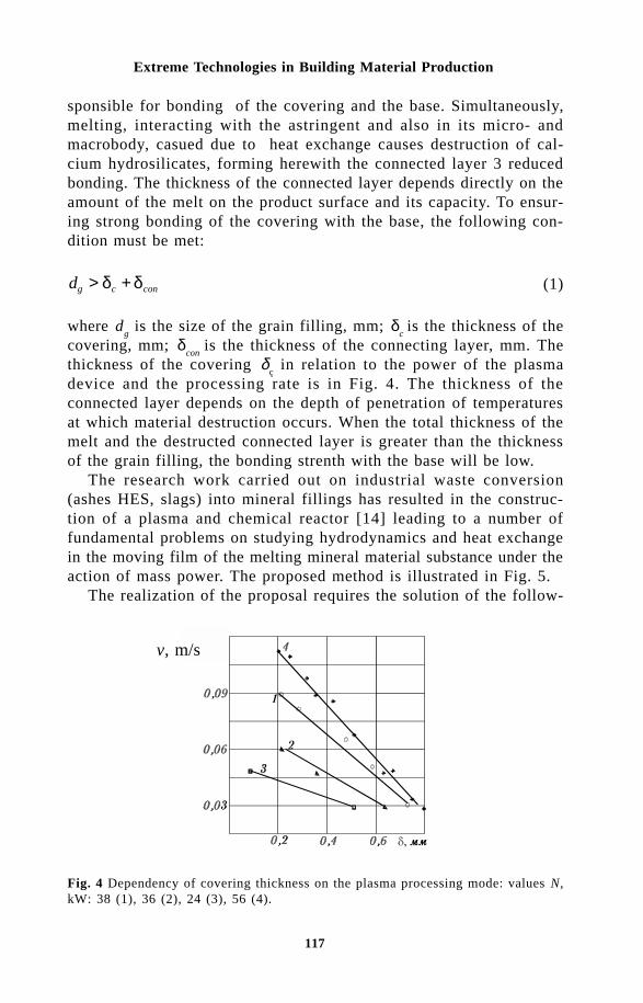
117
Extreme Technologies in Building Material Production
sponsible for bonding of the covering and the base. Simultaneously,melting, interacting with the astringent and also in its micro- andmacrobody, casued due to heat exchange causes destruction of cal-cium hydrosilicates, forming herewith the connected layer 3 reducedbonding. The thickness of the connected layer depends directly on theamount of the melt on the product surface and its capacity. To ensur-ing strong bonding of the covering with the base, the following con-dition must be met:
dg c con> +δ δ (1)
where dg is the size of the grain filling, mm; δ
c is the thickness of the
covering, mm; δcon
is the thickness of the connecting layer, mm. Thethickness of the covering δ
ç in relation to the power of the plasma
device and the processing rate is in Fig. 4. The thickness of theconnected layer depends on the depth of penetration of temperaturesat which material destruction occurs. When the total thickness of themelt and the destructed connected layer is greater than the thicknessof the grain filling, the bonding strenth with the base will be low.
The research work carried out on industrial waste conversion(ashes HES, slags) into mineral fillings has resulted in the construc-tion of a plasma and chemical reactor [14] leading to a number offundamental problems on studying hydrodynamics and heat exchangein the moving film of the melting mineral material substance under theaction of mass power. The proposed method is illustrated in Fig. 5.
The realization of the proposal requires the solution of the follow-
Fig. 4 Dependency of covering thickness on the plasma processing mode: values N,kW: 38 (1), 36 (2), 24 (3), 56 (4).
v, m/s

118
Thermal Plasma Torches and Technologies
Tex
Fig. 5 Schema of heat exchange in the moving melting film on the wall of the RPCR:ω – angular velocity of reactor rotation; 1 – fluid film; 2 – skull; 3 – steel wall, q
n-
total density of heat flow; qw– density of the heat flow in the skull layer; Vmax -
maximum axial velocity of the liquid in the film; Tp – softening temperature; T
n andT
ex – temperature on the internal and external surfaces of the reactor, respectively; δ-thickness of the moving melting film; L1 and L2 – the thickness of the steel wall andthickness of the skull layer; r - radial coordinate, r0 – radial coordinate of phases ofthe liquid–solid section.
ing problems: creating suitable conditions for efficient supply of heatenergy from plasma streams into the dispersed material, conditions forthe shaping of a film of the melting mineral substance in thesemiclosed volume and disintegration of the film in the filling in thefield of centrifugal power. The physical process model can be pre-sented in the following type (Fig. 5): when the rotating homogenisingdevice receives the powder charge, being the pseudo-liquid, the chargehas the shape of a strongly stretched truncated paraboloid, on the sur-face of which a skull layer forsm at the initial moment under insuf-ficient heat energy. Under the action of centrifugal power meltedglassed masses moves on the surface of the skull layer as fine films.It is assumed that at a high velocity of reactor rotation (ω = 50...1001/sec) the melting film is small in comparison with the radius; glassformation took place at the bottom of the reactor; the skull layer due

119
Extreme Technologies in Building Material Production
to its low heat conduction coefficient plays the role of heat isolationin passive heat protection of the walls of the reactor; on the borderbetween the fluid and the hard phase the temperature of the meltingraw materials is the softening temperature; the heat put into the sys-tem partly goes to melting of the mixture of raw materials and is car-ried away together with the moving melting film, but is partly trans-ported through the skull layer in the airstrip of extraction to ventila-tion; heat losses in bands of glass are not taken into account; the heatbalance system forms; the current of film melting is formed and lami-nar; the axial velocity changes along the height of the reactor; tan-gential stress at the liquid–gas border is extremely little; all heatphysical characteristics of glass mass and charge are constant, exceptthe viscosity factor, which is a function of temperature; thethermocapillary effect is not taken into account.
The mathematical problem is based on the given physical modelsand is a system of equations of pulses conservation, energy and massconservation with the corresponding boundary conditions. The changeof pressure defines the movement of the film. It is assumed to pro-portional to the normal pressure created by the centrifugal power inthe elementary volume of the film. The source system is defined byconsidering the assumption on the absence of a correlation betweenthe axial velocity and the vertical coordinate and the initial middlemass temperature and expressing the axial velocity through the den-sity of irrigation. As a result, we get a common differential equationof the third order for the determination of the melting temperature asfunctions of the radius
Θ Θ
ηνν
η= − −
Θ = − =−
ηδ
=δλ
=δλ (2)
where Θ is the dimensionless temperature. For closed systems, weshall consider heat transfer in three layers to the system (Fig. 5):
=
−
+
+
α
αλ λ
= −
λ
= − +
λ λ (3)

120
Thermal Plasma Torches and Technologies
The condition for the determination of the thickness of the layer isa correlation for the heat balance of the system ‘two-layer wall–mov-ing film’ for the higher part of the cylinder where there are conditionsof melting for following fibre creation. The differential equation (2)was determined numerically. To find the beginning of stabilization ofthe current area of the fluid film, the dependence of the Nusseltnumber on the longitudal coordinate was examined. As a result, theinitial heat area is evaluated by the value x/Pe= 5.5, where Pe is thenumber of heat intensity. The middle mass temperature change is de-fined by the Nusselt number. Considering the dependence Nu
p(k/k
0)
on the automodel mode, for the stabilizing current area after approxi-mations of numerical relationships we shall have:
=
−
=
δ ;
=
;
δξ ω
=
;
= = =ν ν λ
;
= −
(4)
Here A is the dimensionless parameter characterizing the heatmode of the viscous flow of the film; ξ is the experimental factortaking into account consumption, dynamic and geometric features; kis the dimensionless friction factor; k
0 is the friction factor for the
parabolic part of the axial velocity; Reω- is the Reynolds number.The correlations obtained for the surface in the four-parameter
space can be used for determining the mean time of melting in thereactor at a specific temperature and allow the selection of the nec-essary parameters of the device for ensuring complete boiling of the

121
Extreme Technologies in Building Material Production
glassmass; in essence, it is the starting point for experimental revisionof the working parameters of a real installation.
Experiments were carried out to check the results of calculationsusing the mathematical model of film current melting on the walls ofthe revolving reactor. The experiments were conducted with meltingof quartz, diopside, basalt and ash. Thickness measurements of themelting film were carried out by the method of frozen layer melting(freeze process). The analysis of the layer structure showed (tracesof spottinesses, directed vertically along the reactor wall) a specificflow direction that confirms the existence of the effect of the tangen-tial stress when defining the boundary conditions. The calculated meanmass temperature was compared to the melt temperature, evaluatedusing a pyrometer. The measured melt temperature and film thick-nesses with the error not more than 20 % are co-ordinated by theassumption that points to the aplicability of dependences obtained withthe limit of the specified inaccuracy for the calculation of technologi-cal parameters of the device.
The results were realizedin the experimental stand Plasma-rotor forthe determinations of the main technological parameters of stablefunctioning of all nodes of the installation, automatic systems andreadings of the measuring instruments. The optimum technological pa-rameters of work of the RPCR with a productivity of 35 kg/hour ofthe filling USING ash GRES-2 as the initial material (Tomsk). Withthe adding of limestone fromthe Kamensk deposit, the parameters wereas follows: power of the plasma device 70 kW; the mass consuptionof raw materials 13 g/sec; angular velocity of rotation of the RPCR400 1/sec; the radius of the cylindrical container 50 mm, height 200mm; the factor of heating intensity under external heat transfer 800W/m2 K.
The filling obtained in plasma technologies has high heat stability,large length of the filament and high tensile strength, so it can find itsuse not only in the building industry but also when making objects offor special applications.
Therefore, using plasma generators in the mineral filament produc-tion allows the use of raw materials with a high content of high-tem-perature oxides with a significant reduction of harmful emission intothe atmosphere and a reduction of the consumption of scarce sourcesof energy (coke, natural gas, etc.); technology is simplified by short-ening some sections of the traditional technological chain and opensa real possibility of the automation of mineral filament production.
The results show that the use of high-concentrated sources of en-ergy (low-temperature plasma) ensures the realization of technologi-
122
Thermal Plasma Torches and Technologies
cal processes in extreme conditions, basing on high-speed (fraction ofa second) physical-chemical reactions, instant changes of the charac-teristics of processing material and ensuring a one-stage technologi-cal process.
In this connection, it is possible to say that the decision on theproblem of development and making of new materials with specificcharacteristics, based on technological processes under extreme con-ditions, is highly promising and ensures the maximum useful productwith minimum power expenditure.
References1 G.G. Volokitin and B.P. Romanov, Study of phase transformations of
calcium hydrosilicates under plasma processing. Use of low temperatureplasma in technologies of inorganic materials and powder metallurgy,Report All-Union. conf., Riga, Zinatne (1985), pp.128-135.
2 G.G. Volokitin, et al, In: Physical and chemical glass-type covering studies, when processing the surface of silicale material by low-temperatureplasma. Use of low-temperature plasma in technologies of inorganicmaterials and powder metallurgy. Report All-Union. conf., Riga, Zinatne(1985), pp.136-143.
3 G.G. Volokitin, et al, Thermodynamic process studies, running on surfacesof silicate bricks when processing it by low-temperature plasma, TomskState University of Architecture and Building, Tomsk (1986).
4. G.G. Volokitin, et al, In: Calculation of heat fields in the area of an silicatebrick in processing by low-temperature plasma. Generators of low-tem-perature plasma: Thes. Report. XI All-Union conf. generators of low-temperature plasma, Novosibirsk (1989), pp.324-325.
5 G.G. Volokitin, Generalised process model of forming glass-type coveringon building products under plasma processing, Izv. Sib. Otd. AN SSSR,Tekh. Nauk, (1990), p.99-102.
6 V.E. Borzych, In: Works of III Minsk International Forum on Heat MassTransfer, Minsk (1996.), ANK
7 M.E. Ermolaev, et al, Building materials, No.7, 21 (1976).8 P.V. Pashtskiy and T.V. Kusina, Fiz. Khim. Obrab. Mater., No.3, 37-39
(1987).9 A.B. Demidovich, et al, Eng. Phys. Journal, No.3, 461-466 (1984).1 0 I.O. Bugs, et al, Influence of heating on structured conversions in silicat
products, Izv. AN SSSR, (1983), p.10.11 R.C. Guger and B.V. Ovchinskiy, The Elements numerical analysis and
mathematical processing the results experiment.- 2 issue, SciencePublishing (1970).
1 2 Ch.F. Taylor, Chemistry of Cements, Moscow, Building Publish (1969),1 3 I.V. Kuzmin and V.A. Kedruev, Basis of theory information and coding,
Kiev High school (1977).1 4 G.G. Volokitin, et al, Patent 2000977 Russia. Method of producing mineral
filament by plasma heating (Russia).- 93057718/33,

123
Achievements of Plasma Tomography
V.V. Pickalov
Recent years are characterized by the fast development of computationalphysics, because the progress in modern computers has made it possibleto investigate more complicated physical phenomena in numericalsimulations. This is also valid for research into gas- and fluid dynamics,in plasma physics. It is possible now to get three-dimensional spaceand time characteristics of gas and plasma flows, with dynamic volumevizualization of the numerical data.
To verify some theoretical models of physical phenomena, one needsto compare theoretical calculations with experimental data. At this point,a researcher has often difficulties, because he has to compare the multi-dimensional modelling computations with the experimental diagnosticdata, which are only available at a set of points or lines, and very oftenthey are averaged in time.
Computerized tomography is a link between the experiment and thetheory, it gives a tool to the experimentalist and the theoretician foran adequate comparison of the theoretical calculations with the experimentalmeasurements [47,49]. Tomography methods allow one to treat suchmeasurements with proper space and time resolution, and then to getexperimental data in such a form, which makes the comparison of thetheory and the experiment to be possible.
This paper gives a review of modern optical tomography techniques,and corresponding two- and three-dimensional algorithms are also discussed.Special emphasis is laid on the synthesis of tomography approacheswith the new image processing technique.
Some examples of the new methods of tomography for incompletedata, local and pseudo-local tomography of high gradient structures arediscussed.
Institute of Theoretical and Applied Mechanics, Novosibirsk 630090, Russia

124
Thermal Plasma Torches and Technologies
!"##$ !$$Up to now tremendous effort have been applied to resolve spatial featuresof low temperature plasma with the help of plasma tomography methods.
Well developed optical techniques for side observations of plasmahave been used in plasma tomography: emission [3,4,33,34,48,49], inter-ferometry [7,29,30,55,61], schlieren technique [14], etc.
Up to now different experimental tomography systems have been appliedfor diagnostics of different kinds of plasmas: thermal [32-38,49] [46,50,53,57], low pressure [52,51], high frequency discharge [15], hightemperature plasmas [8,9,16,20,39], [40-45,54], and others.
It is known that in physical applications of tomography the followingproblems complicated the diagnostics procedure:
- small number of angles of view K;- small number of detectors for each angle N
p;
- limited angle problem;- limited region of impact parameters p;- random noise in data;- non-parallel arrangement of line integration system;- finite width of the detectors;- apparatus distortions of the signal measuring system;Such problems sometimes make the interpretation and evaluation stages
of tomogram treatment very difficult.Most of these problems can be illustrated by the Radon transform.
Indeed, in mathematics the Radon transform for two-dimensional functionsg(x,y) means the integrals over it along straight lines [11,17,22,44,49]:
f p g x y dlp( , ) ( , ) ,x x=-•
• (1)
For simplicity, we will treat g(x,y) as a distribution of local emis-sivity coefficients, and f(p,ξ) as an integral emission of two-dimensionalplasma cross-section along the line with impact parameter p and an-gle ξ to the axis X (see Fig.1, [49]).
The Radon transform has an analytical inversion, namely (2D case):
g x y df p dp
p p( , )
( , )
( ),= -
--•
•1
2 20
20px xp
(2)
Thus, for reconstruction of the plasma image we need experimentalmeasurements of emission projections f (p,ξ) for the angles inside theregion ξ∈ [0, π] and impact parameters p∈ [–R
0, R
0], where R
0 is a radius

125
Achievements of Plasma Tomography
of the circle which includes the whole plasma object inside. Thoughusually Eq. (2) is not used for practical tomography, it shows all troubleswith our inverse problem. For it we need parallel geometry of dataacquisition, e.g. a set of parallel lines for detecting system. Then thenoise in data could be significantly enlarged after reconstruction, becauseof singularity of the internal integral (which is called the convolutionor filtration integral).
Many of the problems mentioned above have some known solutions,e.g. regularization procedures against noise [56], but others have to besolved yet.
In particular, when information about plasma is space irregular itis possible to extract more information for some regions than for others.From the published literature ([11,44,49]) we know some attempts touse Region of Interest (ROI) tomography approaches for the so-calledexterior Radon problem, when the data are measured for all angles x,but only for those p which are outside some circle ρ
0: | p | > ρ
0. It
was found that the solution of this problem is unique, but very unstable.In this case the measurements give information only about external regionsoutside of the circle of radius ρ
0, and internal regions have no influence
on the resulting integrals.On the opposite, the internal Radon problem means the reconstruction
of image inside a circle with radius ρ0, when the limitations for measured
data are in the form | p | < ρ0. In this case there are much more un-
certainties in data, because external regions have input to any line whichcomes through the internal region.
Possible approaches to solve the internal Radon problem are:- to use the maximum of a priori information and to make some
Fig.1 The scheme of plasma emission measurements.

126
Thermal Plasma Torches and Technologies
kind of extrapolation procedures to get projections of plasma emissionsin those parts, where such projections were not measured; the first stepsin this direction were made in our papers [19,20];
- to try to restore not exact values of local emissions, but to geta so-called local tomogram which keeps main geometrical features ofthe exact tomogram, and for such restoration those methods need in-tegral measurements only for lines that come through a given point (x
0,y
0).
Thus, as the first step in the solution of low-informative tomographyproblem one could suggest to use local tomograms, and first of all Vainbergimage [58] and summation image [2,49].
The following algorithms that can be used for the aims of plasmaflow visualization are based on wavelet decompositions [60] as a toolfor another localization type of tomograms, or pseudolocal tomograms[23,24].
Local tomograms give us an approximate image of the plasma cross-section, which shows the main geometrical features of the phenomenaunder investigation. It gives us information about positioning of highgradients in plasma, and shows the main flows in it.
But even getting such local tomograms involves some more diffi-culties,namely:
- possible low space resolution of detecting system, when the widthof detector is larger than the size of plasma structures of interest;
- limited angle covering, when detectors look into plasma only inthe region | ξ | < ξ
0 < π.
The next section illustrates some items discussed above.
%## !"& '"$Usual tomography is global in the sense that Radon inversion at thepoint (x
0, y
0) depends upon the all integrals f(p, ξ) of the object g(x,y)
(see Eq.(2). Such nonlocality forces the usage of all data in the standardalgorithm even if we are interested only in a small region of the object.And local methods could reduce sometimes the data acquisition timeand the volume of experimental measurements.
In the papers of Faridani [12,13] a L-operator was introduced, whichgives the edge detection algorithm and yields a local tomogram. Muchearlier this operator was involved in practical tomographical devicesby E.Vainberg [58], and we call such tomogram a Vainberg image. Faridaniwith co-workers really have used a combination of Λ operator and itsinverse Λ–1 (which is also local and occurs to be a summation image):
g g gF = + −Λ Λµ 1 . (3)
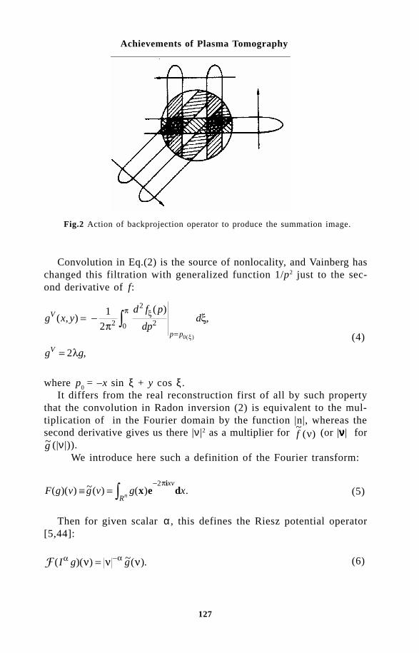
127
Achievements of Plasma Tomography
Convolution in Eq.(2) is the source of nonlocality, and Vainberg haschanged this filtration with generalized function 1/p2 just to the sec-ond derivative of f:
g x yd f p
dpd
g g
V
p p
V
( , )( )
,
,
( )
= -
=
=
1
2
2
2 0
2
2
0
px
l
p x
x (4)
where p0
= –x sin ξ + y cos ξ .It differs from the real reconstruction first of all by such property
that the convolution in Radon inversion (2) is equivalent to the mul-tiplication of in the Fourier domain by the function |n|, whereas thesecond derivative gives us there |ν |2 as a multiplier for ~
( )f n (or |ννννν| for~g (|ν |)).
We introduce here such a definition of the Fourier transform:
F g v g v g xR
xv
n( )( ) ~( ) ( ) .∫ = -
x e di2p
(5)
Then for given scalar α , this defines the Riesz potential operator[5,44]:
( )( ) ~( ).I g ga an n n= - (6)
Fig.2 Action of backprojection operator to produce the summation image.

128
Thermal Plasma Torches and Technologies
For n-dimensional case, if α < n, then the general inverse Radon transformis [44]:
g I R I R gn= - + -12
1a a x# , (7)
where Rξg is the n-dimensional Radon transform, and R# is the backprojection operator.
For Laplacian operator ∆, we have I − = −22
1
4π∆, and
Dg I g I R I R gn= - = -- - - + -4 22 2 2 2 1p p a ax
# . (8)
The operator I − = −1 1
2π∆ is called the Lambda operator (it is also
known as Calderon’s operator, see [12]):
Lg I g I R I R gn= =- - + -1 112
a ax
# , (9)
and taking α = –1, we have
Lg R I R gn= -12
# x (10)
and its inverse
L- -=1 212
g R I R gn# .x (11)
For our case of two-dimensional tomography n = 2, and equations (10)and (11) yield:
Lg R I R g= -12
2# ,x (12)
Λ− =1 1
2g R R g# .ξ (13)

129
Achievements of Plasma Tomography
Now, we have the relations between Λ-tomography, summation image[59]:
g x y f p dS( , ) ( ( )) ,= 12 0
0px xx
p (14)
and the Vainberg image (4):
V g ggV= = 2Λ , (15)
g gS = −1
21
πΛ . (16)
Finally, for Faridani image gF we have:
g gF V S= +1
22πµ . (17)
It should be emphasized here that an exact reconstruction of g(x,y)from only line integrals which pass through the region of interest isimpossible in the general case [44], so instead we put the problem ofapproximate estimation of this function or of some special features, suchas locations of discontinuities, general geometrical characteristics, etc.
3.1. Local tomography in 3DThe 3D generalization of the Vainberg method is presented in the followingway
g P L f gVn( ) ( ) ,#x = 2 (18)
where L2 is a 2D Laplace operator and P# is the operator of 3D
backprojection [44].To get the Vainberg image one has to process each projection by
the Laplace operator and then to perform 3D backprojection. Using theconnection between the Laplace and Fourier operators one can rewrite(18) as
g F P v F fvn( ) | | ( ) .#x g= -1
4 31 2
2p (19)

130
Thermal Plasma Torches and Technologies
where F3–1 is the operator of 3D inverse Fourier transform. The Vainberg
image yields amplification of the high frequency components in comparisionwith the exact tomogram.
Some results of numerical simulations are presented in Fig.3. Fig-ure 3a is a cross-section of a three-dimensional phantom, and Fig.3bshows the Vainberg image for this phantom reconstructed from 25 two-dimensional projections (from [28]).
#$As was shown, local tomography can give promissing results for theproblems of gas and plasma flow vizualization. Further developmentof reconstruction algorithms could be based in some of it parts on modernwavelet analysis [1,10,21,31], which is already penetrating into tomographymethods [6,18,60].
Wavelet decomposition can be used as a tool for noise reduction throughthe wavelet shrinkage approach [25,26] or for some contrasting filteringof projections before their processing by A usual tomography filter.
This work was partially supported by RFBR (Russia), DFG and BMBF(Germany).
References1 A. Aldroubi and M. Unser (eds), Wavelets in medicine and biology, Boca
Raton, CRC Press (1996), p.616.2 H.H. Barrett and W. Swindell, Analog. reconstruction methods for transaxial
tomography, Proc. IEEE, Vol.65, No.1 (1977), pp.89-107.3 D.M. Benenson and A.J. Baker, AIAAJ., 9, No.8, 1441-1446 (1971).4 D.M. Benenson and A.A. Cenkner, Trans. ASME. Ser. C.J. Heat Transfer,
92, No.2, 276-284 (1970).5 C.A. Berenstein and D.F. Walnut, Wavelets and local tomography. Wavelets
in medicine and biology, A. Aldroubi and M. Unser (eds), Boca Raton,CRC Press (1996), pp.231-261.
6 M. Bhatia, et al, IEEE Trans. Med. Imag., 15, No.1, 92-101 (1996).
Fig.3 Cross sections of 3D phantom and its Vainberg image.

131
Achievements of Plasma Tomography
7 S. Cha and C.M. Vest, Appl. Opt., 20, No.16, 2787-2794 (1981).8 R.C. Chase, et al, Opt. Eng., 20, No.3, 486-492 (1981).9 D.F. Da Cruz Jr. and A.J.H. Donn'e, Rev. Sci. Instrum., 61, No.10, 3067-
3069 (1990).10 I. Daubechies, Ten lectures on wavelets, SIAM, Philadelphia (1992), p.357.11 S.R. Dean, The Radon transformation and some of its applications, John
Wiley, New York (1983), p.289.12 A. Faridani, Results, old and new, in computed tomography. Inverse
problems in wave propagation, G. Chavent et al (eds), The IMA vol-umes in math. and appl., Vol.90, Springer Verlag, New York (1997), pp.167-193.
13 A. Faridani, et al, J. Appl. Math., 52, 459-484 (1992).14 G.W. Faris and R.L. Byer, Opt. Lett., 12, No.2, 72-74 (1987).15 E.F. Gippius, et al, Tomography research of the transversal HF-discharge
plasma, ESCAMPIG-92, St Petersburg, EPS, Vol.16F (1992), pp.330-331.
16 R.S. Granetz and P. Smeulders, Nucl. Fusion, 28, No.3, 457-476 (1988).17 G.T. Herman, Image reconstruction from projections: The fundamentals
of computerised tomography, Academic Press, New York (1980), p.316.18 M. Holschneider , Inverse Problems, 7, 853-861 (1991).19 L.C. Ingesson, et al, Rev. Sci. Instrum., 66, No.1, 622-624 (1995).20 L.C. Ingesson and V.V. Pickalov, J. Phys. D: Appl. Phys., 29, No.12,
3009-3016 (1996).21 G. Kaiser, A friendly guide to wavelets, Birkhauser, Boston (1994), p.300.22 A.C. Kak and M. Slaney, Principles of computerised tomographic imaging,
IEEE Press, New York (1988), p.329.23 A.I. Katsevich and A.G. Ramm, Inverse Problems, 11, No.5, 1005-1023
(1995).24 A.I. Katsevich and A.G. Ramm, J. Appl. Math., 56, No.1, 167-191 (1996).25 E.D. Kolaczyk, J. Amer. Stat. Assoc., 91, No.9, 1079-1089 (1996).26 E.D. Kolaczyk, An application of wavelet shrinkage to tomography. Wavelets
in medicine and biology, A. Aldroubi and M. Unser (eds), Boca Raton,CRC Press (1996), pp.77-92.
27 A.V. Likhachov and V.V. Pickalov, Nucl. Instrum. Meth. Phys. Res. (A),359, No.1-2, 370-375 (1995).
28 A.V. Likhachov and V.V. Pickalov, Nucl. Instrum. Meth. Phys. Res. (A),(1998) (to appear).
29 I.H. Lira and C.M. Vest, Appl. Opt., 26, No.5, 774-776 (1987).30 I.H. Lira and C.M. Vest, Appl. Opt., 26, No.18, 3919-3928 (1987).31 A.K. Louis, et al, Wavelets: Theory and Applications, John Wiley, Chichester
(1997), p.324.32 C.D. Maldonado and H.N. Olsen, JOSA, 56, No.10, 1305-1313 (1966).33 T.S. Melnikova and V.V. Pickalov, Beitr. Plasmaphysik, 22, No.2, 171-
180 (1982).34 T.S. Melnikova and V.V. Pickalov, Beitr. Plasmaphysik, 24, No.5, 431-
445 (1984).35 T.S. Melnikova and V.V. Pickalov, The electric arc in a gas flow, Proc.
17th ICPIG, Budapest, Contr. papers, Vol.2 (1985), pp.789-791.36 T.S. Melnikova and V.V. Pickalov, Soviet Journal of Applied Physics -
Scripta Technica, 1, No.6, 61-70 (1987).37 T.S. Melnikova and V.V. Pickalov, Computer-aided plasma tomography.

132
Thermal Plasma Torches and Technologies
High-temperature dust-laden jets in plasma technology, O.P. Solonenkoand A.I. Fedorchenko (eds), Proc. Intern. Workshop, Novos., USSR (1988),VSP, Utrecht, The Netherlands (1990), pp.257-282.???
38 C.A. Monnig, et al, Spectrochimica Acta (B), 43, No.9-11, 1217-1233(1988).
39 B.R. Myers and M.A. Levin, Rev. Sci. Instrum., 49, No.5, 610-616 (1978).40 Y. Nagayama, Jpn. J. Appl. Phys., 24, No.6, 787-788 (1985).41 Y. Nagayama, J. Appl. Phys., 62, No.7, 2702-2706 (1987).42 Y. Nagayama and A.W. Edwards, Rev. Sci. Instrum., 63, No.10, 4757-
4759 (1992).43 Y. Nagayama, et al, Phys. Rev. Lett., 61, No.16, 1839-1842 (1988).44 F. Natterer, The mathematics of computerised tomography, Wiley, New
York (1986), p.222.45 A.P. Navarro, et al, Rev. Sci. Instrum., 52, No.11, 1634-1643 (1981).46 H.N. Olsen, et al, JQSRT, 8, 1419-1430 (1968).47 V.V. Pickalov and N.G. Preobrazhenskii, Sov. Phys. Usp. (AIP), 26, No.11,
974-990 (1983).48 V.V. Pickalov and T.S. Melnikova, Beitr. Plasmaphysik, 24, No.4, 417-
430 (1984).49 V.V. Pickalov and T.S. Melnikova, Plasma tomography [in Russian], Nauka,
Novosibirsk (1995), p.229.50 A. Plessl, Appl. Phys., 21, No.4, 377-389 (1980).51 W. Schielke, et al, Surface and Coating Technology, 74-75, 552-561
(1995).52 W. Schielke, Surface and Coatings Technology (1998) (to appear).53 N. Sebald, Appl. Phys., 21, No.3, 221-236 (1980).54 S. Sugimoto, et al, J. Appl. Phys., 66, No.11, 5228-5231 (1989).55 D.W. Sweeney and C.M. Vest, Intern. J. Heat and Mass Transfer, 17,
No.12, 1443-1454 (1974).56 A.N. Tikhonov and V.Y. Arsenin, Solutions of ill-posed problems, Winston,
New York (1977).57 W. Tiller, Appl. Phys., 25, No.3, 317-328 (1981).58 E.I. Vainberg, et al, Soviet J. Non-dest. Test, 17, 415-423 (1981).59 G.N. Vishnyakov, et al, Opt. Spectrosc. (USSR), 62, No.6, 803-806 (1987).60 D. Walnut, Local inversion of the Radon transformation in the plane using
wavelets. Wavelet Application in Signal and Image Processing, Proc.SPIE, Vol.2034, San Diego, C.A. (1993), pp.84-91.
61 Yu.A. Zakharenkov, et al, Laser and Particle Beams, 8, No.1-2, 339-342 (1990).
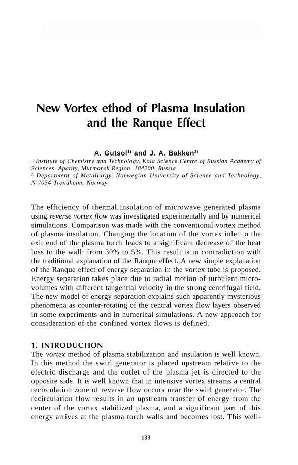
133
New Vortex Method of Plasma Insulation and the Ranque Effect
A. Gutsol1) and J. A. Bakken2)
1) Institute of Chemistry and Technology, Kola Science Centre of Russian Academy ofSciences, Apatity, Murmansk Region, 184200, Russia2) Department of Metallurgy, Norwegian University of Science and Technology,N-7034 Trondheim, Norway
The efficiency of thermal insulation of microwave generated plasmausing reverse vortex flow was investigated experimentally and by numericalsimulations. Comparison was made with the conventional vortex methodof plasma insulation. Changing the location of the vortex inlet to theexit end of the plasma torch leads to a significant decrease of the heatloss to the wall: from 30% to 5%. This result is in contradiction withthe traditional explanation of the Ranque effect. A new simple explanationof the Ranque effect of energy separation in the vortex tube is proposed.Energy separation takes place due to radial motion of turbulent micro-volumes with different tangential velocity in the strong centrifugal field.The new model of energy separation explains such apparently mysteriousphenomena as counter-rotating of the central vortex flow layers observedin some experiments and in numerical simulations. A new approach forconsideration of the confined vortex flows is defined.
!The vortex method of plasma stabilization and insulation is well known.In this method the swirl generator is placed upstream relative to theelectric discharge and the outlet of the plasma jet is directed to theopposite side. It is well known that in intensive vortex streams a centralrecirculation zone of reverse flow occurs near the swirl generator. Therecirculation flow results in an upstream transfer of energy from thecenter of the vortex stabilized plasma, and a significant part of thisenergy arrives at the plasma torch walls and becomes lost. This well-

134
Thermal Plasma Torches and Technologies
known phenomenon demands sufficient cooling of the plasma torch walls.Apart from power losses the existence of a reverse flow along the
axis of intensive swirled flows can have other unpleasant consequences.So, in our experiments on processing of fluoride solutions of rare re-fractory metals salts [1, 2] the reverse flow in the microwave (MW)plasma generator (Fig. 1a) brought a portion of solution sprayed in thetop part of the plasma chemical reactor 4, specifically in the connectingcone 5, into the MW discharge zone 3. It resulted a considerable modifieddischarge regime, that was observed as a change of its color, and achange of the magnetron current, which is affected by the microwavepower reflected from the discharge. Besides, interaction of the fluo-ride solution and its decomposition products with the quartz tube 1 ofthe MW plasmatron reduced the service life of this tube and resultedin pollution of the produced oxides by silicon.
To prevent penetration of the solution into the plasmatron we re-placed the cylindrical discharge tube with a specially made tube (Fig.2) with quartz ribs 2 welded on the outlet end. It was possible to observethat the plasma flow from the standard cylindrical tube into ambientair was divergent, while the tube with ribs formed a jet of plasma.
Though the reduction of length of the reverse flow zone suppressedpenetration of the solution into the plasmatron, it, probably, did not improve
a b
2
1
3
5
4
6
7
Fig. 1 Scheme of the MW plasma torch with supposed flow patterns of gas and plasma.(a) - “old” scheme with flow patterns for conventional vortex plasma stabilization;(b) - “new” scheme with flow patterns for reverse vortex plasma stabilization. 1 -cylindrical quartz tube; 2 - original swirl generator; 3 - plasma; 4 - plasma chemicalreactor; 5 - connecting cone; 6 - water-cooled diaphragm; 7 - additional swirl generator.

135
New Vortex Method of Plasma Insulation and the Ranque Effect
significantly the power characteristics of the plasma generator, and thethermal losses still were rather high as testified by intensive heating(up to luminescence) of the outlet end of the modified quartz tube.
According to the new concept of plasma insulation [3, 4] based onthe idea of reverse vortex formation [5] the outlet of the plasma jetis directed to the swirl generator side. In this case the plasma gas shouldenter the discharge zone from all sides except the outlet side, and nosignificant recirculation zone should be formed.
Flow pattern in the conventional vortex unit (Figure 1a) should besimilar to that in uniflow vortex tube, and in reverse vortex unit (Figure1a) should be similar to that in the most effective counterflow vortextube [6, 7]. So, it seems reasonable to compare the results of inves-tigation for efficiency of thermal insulation in two mentioned vortexsystems with a theory of the Ranque effect.
" #$Experiments were made with a microwave (MW) plasma generator witha MW power input up to 5 kW. This plasma torch is a part of anexperimental facility for treatment of inorganic salt solutions [1, 2]. A
Fig. 2 Scheme of the modified discharge tube for MW plasma torch. 1 - cylindricalquartz tube; 2 - welded quartz ribs.
1 2

136
Thermal Plasma Torches and Technologies
sketch of the MW plasma torch with supposed flow patterns of gasand plasma is shown in Fig. 1 [3, 4]. The quartz discharge tube 1 (innerdiameter 44 mm, length about 140 mm) passes perpendicularly throughtwo wave-guides (90´45 mm2, unshowed) which supply H
10 mode of
the MW energy (frequency 2.4 GHz) from two magnetrons. In theconventional scheme (Fig. 1a) the plasma gas (air or nitrogen) entersthe discharge chamber through four inlet openings of the original tangentialswirl generator 2, resulting in stabilization of the plasma 3 on the axisof the quartz tube 1 by the strong rotation of the gas. In the experimentalplasma-chemical set-up [1, 2] the MW plasma torch is joined to theuncooled massive steel reactor 4 by an uncooled steel connecting cone5.
For experiments with reverse vortex stabilization (Fig. 1b) an additionalvortex generator 7 with a water-cooled diaphragm 6 (diameter 26 mm)was installed between the quartz tube and connecting coin. Calorimetricand electrical measurements permitted to determine the MW power inputW
p into the discharge and the heat losses W
t to the water-cooled parts
of the plasma torch. (Unfortunately it is not possible to use water coolingfor the quartz tube of the MW plasma torch, but as this tube is sur-rounded by the water-cooled parts of the plasma torch almost on allsides, it was supposed practically all the heat from the quartz tube endsup in the cooling system due to convection.)
The experimental results [3, 4] are presented in Fig. 3 (dots withfull curves) in dependence on J - the energy input into the dischargeper unit mass of plasma gas consumption. The power input was around3.5 kW and varies a little due to the fact that changing the gas flowconditions also influences the discharge conditions. The dots of curve1 were obtained for the “old” scheme (Fig. 1a) without the diaphragmand with the plasma-chemical reactor. Curve 2 corresponds to the samescheme, but with the diaphragm. Curve 3 corresponds to the “new”reverse vortex flow scheme (Fig.1b) with the reactor. As the heat fluxto the plasma torch walls from the reactor was significant, two ad-ditional series of experiments were made. The reactor was removed,the plasma torch was turned upside-down, and a hot plasma jet wasdirected upwards into ambient air. As the heat losses in the “old” schemewithout the diaphragm were extremely large for all energy inputs, onlythe “new” scheme (Fig. 1b) was used in the additional experiments.Plasma gas might be supplied through the original vortex generator (2,Fig.1) for realizing the conventional vortex stabilization scheme, or throughthe additional vortex chamber (7, Fig. 1) for realizing the reverse vortexscheme of plasma stabilization. Curves 2' and 3' (Fig. 3) correspondto these two cases.

137
New Vortex Method of Plasma Insulation and the Ranque Effect
J [kJ/g]
0
10
20
30
40
50
2’
Wt /Wp [%]
1 2 3 4
3’ 3
1
2
The experimental investigation showed that if the plasma was stabilizedby the conventional vortex flow the energy loss to the plasma torchwalls might exceed 30 %. With the reverse vortex flow the energyloss was only about 5 %. The heat loss in a simple system of this typecorresponds to the low heat loss in plasma generators with a porousdischarge chamber, which, however, is very complex end expensive tomanufacture. More over, if the reverse vortex flow configuration isused, almost all the plasma forming gas should pass through the dis-charge zone. As the axial velocity in the “top” region of the reversevortex should be quite low, discharge stability problems should not occur.As the flow direction should be constant throughout the axial region,it seems possible to inject additional gas or particles into the “top” ofthe reverse vortex. Tests with ZrO
2+Y
2O
3 powder were made in the
described MW facility. The introduction of the powder into the “top”of plasma torch with the reverse vortex flow plasma stabilization ensuresmelting and spheroidization of particles up to 100 mm.
So, the reverse vortex system seems very promising for differentplasma-chemical processes and other technical applications utilizing mi-
Fig.3 Heat losses in the microwave plasma generator. Full curves - experiments, brokencurves - numerical simulations. 1 - old scheme without the diaphragm and with theplasma-chemical reactor; 2 - old scheme with the diaphragm and with the plasma-chemical reactor; 2' - old scheme with the diaphragm and without the plasma-chemicalreactor (experiment and simulation); 3 - new scheme with the diaphragm and withthe plasma-chemical reactor; 3' - new scheme with the diaphragm and without theplasma-chemical reactor (experiment and simulation).

138
Thermal Plasma Torches and Technologies
crowave plasma devices as well as DC and AC plasmatrons, RF in-duction plasma torches, and probably gas burners.
% !&' $ '&$The numerical simulations of the MW plasma torch were made usingthe fluid flow and heat transfer simulation program Fluent. In the 2Daxisymmetric geometry the conservation equations for mass, energy andradial, axial and azimutal momentum were solved simultaneously. It isworth while to make a few remarks on our experience with the FLUENTprogram.
First, it should be noted that the simulation of rotating flows requiresan order of magnitude more computational time, than simulation of flowswithout rotation in the same geometry.
The second remark concerns the till now widely used use k-ε modelof turbulence. The program allows to carry out simulation using variousmodifications of this model, and with the Reynolds Stress Model (RSM)for turbulence. The second model involves calculation of the individualReynolds stresses. The improved versions of the FLUENT programallow to take into account the directional diffusivity of turbulence anda non-equilibrium wall function. In the recommendations concerning waysof simulating flows in mass force fields, and, in particular, of rotatingflows, it is noted that the k-ε model gives considerably less exact results,than the Reynolds Stress Model. However, simulations using the k-εmodel require much less time. So, it is recommended to start a simulationwith the help of the k-ε model, and then to use the results obtainedas the first approximation for next simulations.
Our experience with trial simulations of elementary rotating flowshas shown, that in some cases the application of the k-ε model givescompletely unrealistic results, the use of which even as the first ap-proximation can only complicate further simulation. As an example wedemonstrate in Fig. 4 the obtained stream lines in the axial plane forthe rotating flows of water. The water enters tangentially into the cylindricalvessel (diameter 44 mm, length 100 mm) through a circular slit (width2.5 mm) and leaves the vessel through the diaphragm (diameter 26 mm)in one end. The incoming velocity of water is 1 m/s and the initial tangentialvelocity is 10 m/s. The slit is located on the cylindrical surface (Fig.4-1) next to the end with the diaphragm or on this end (Fig. 4-2 and4-3). It is quite obvious that the flow patterns in all these cases shouldbe similar, but simulation using the k-ε model of turbulence for twomodels gives completely different pictures (Fig. 4-1 and 4-2), whichdiffer not only by the size of a recirculation zone, but even by the flowdirection in this zone. At the same time, simulation with use of the RSM
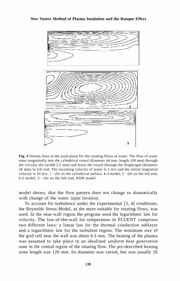
139
New Vortex Method of Plasma Insulation and the Ranque Effect
1
2
3
Fig. 4 Stream lines in the axial plane for the rotating flows of water. The flow of waterenter tangentially into the cylindrical vessel (diameter 44 mm, length 100 mm) throughthe circular slit (width 2.5 mm) and leave the vessel through the diaphragm (diameter26 mm) in left end. The incoming velocity of water is 1 m/s and the initial tangentialvelocity is 10 m/s. 1 - slit on the cylindrical surface, k-ε model; 2 - slit on the left end,k-ε model; 3 - slit on the left end, RSM model.
model shows, that the flow pattern does not change so dramaticallywith change of the water input location.
To account for turbulence under the experimental [3, 4] conditions,the Reynolds Stress Model, as the more suitable for rotating flows, wasused. In the near-wall region the program used the logarithmic law forvelocity. The law-of-the-wall for temperature in FLUENT comprisestwo different laws: a linear law for the thermal conduction sublayerand a logarithmic law for the turbulent region. The minimum size ofthe grid cell near the wall was about 0.3 mm. The heating of the plasmawas assumed to take place in an idealized uniform heat generationzone in the central region of the rotating flow. The pre-described heatingzone length was 120 mm. Its diameter was varied, but was usually 26

140
Thermal Plasma Torches and Technologies
mm. The metallic parts of the plasma generator were supposed to havea constant temperature of 300 K. On the cylindrical wall convectivecooling with a heat transfer coefficient of 50 W m-2 K-1 and radiationcooling with an external emissivity of 0.8 were assumed. Test calcu-lations showed that the most realistic flow pattern in the inlet regionswas obtained in a 2D geometry when the discrete tangential gas in-let jets were simulated by fixing the rotating velocity in the cells nextto the cylindrical wall and defining the appropriate mass sources forthe same cells.
Figure 5 shows on the axis plane the stream lines, profiles of axialvelocity and the temperature distribution for the conventional vortexscheme, and Figure 6 - for the “new” reverse vortex flow scheme.In these two modeling cases the heating zone (3.5 kW, length 0.14 m,diameter 44 mm) was in the center of MW plasma torch quartz tube(1, Figure 1). Gas (nitrogen) enters tangentially into discharge chamber(conventional scheme) or into an additional vortex chamber (“new” reversevortex flow scheme). The initial velocity of the tangential gas jets wereestimated from the experimental data of the pressure drop and the gasconsumption. In two cases showed in Figures 5 and 6 the initial tan-gential velocities (and the gas consumption) are equal 100 m/s (1 g/s) and 225 m/s (1.5 g/s) accordingly. It is easy to see (Fig. 6) that
300 1130 1960 2790 3620 4440 5270 6100
Temperature [K]
Fig.5 Temperature distribution, stream lines and profiles of axial velocity for threedifferent cross-sections and for outlet of the MW plasma torch with conventionalvortex flow. Numerical simulations for the uniform heat source (power 3.5 kW; length0.12 m; diameter 26 mm) in the center of the “old” MW plasma torch (length 0.14 m;diameter 44 mm). Gas (nitrogen, 1 g/s) enters tangentially with velocity 100 m/s throughfour narrow inlet openings into the discharge chamber. The recirculation flow resultsin an upstream transfer of energy from the center of the vortex stabilized plasma.

141
New Vortex Method of Plasma Insulation and the Ranque Effect
the reverse vortex “compresses” the heat zone and protects the plasmatorch walls from overheating. As it was supposed [3-5], the main partof the plasma gas passes through the high temperature discharge zoneand size of recirculation zones are considerably reduced. In the “old”scheme (Fig. 5), on the contrary, the main part of the incoming gasmixes with hot recirculated flow and moves along the cylindrical quartzwall thus bypassing the discharge zone. The calculated energy lossesfor the appropriate cases are shown by dots of the broken curves onFig. 3 (curve 2' - for the conventional vortex scheme, curve 3' - forthe “new” reverse vortex flow scheme). A discrepancy between ex-perimental and calculated results may occur due to the oversimplifieddescription of the discharge zone, and probably also because of ex-perimental errors. Nevertheless, this discrepancy is small enough to concludethat the energy losses might be reliably predicted for other electric dischargesand in flames by employing numerical simulation models.
(!&!)**&&'&+ ,,!*-The results of experiments and numerical simulations of conventional
Temperature [K]
285 833 1380 1930 2480 3030 3580 4120
Fig.6 Temperature distribution, stream lines and profiles of axial velocity for threedifferent cross-sections and for outlet of the MW plasma torch with reverse vortexflow. Numerical simulations for the uniform heat source (power 3.5 kW; length 0.12m; diameter 26 mm) in the center of the “new” MW plasma torch (length 0.14 m;diameter 44 mm). Gas (nitrogen, 1.5 g/s) enters tangentially with velocity 225 m/sthrough three narrow inlet openings into the additional vortex chamber (swirl generator).The reverse vortex “compresses” the hot zone and protect the plasma torch wallsfrom overheating.

142
Thermal Plasma Torches and Technologies
and reverse vortex flow systems contradict the traditional theory ofthe Ranque effect [6, 7].
It is worth while noting that modern ideas about the properties andpossibilities of confined vortex flows are quiet contradictory. Confinedvortex flows are widely used in different devices with different, of-ten opposite aims. So in vortex and cyclones combustors vortex flowsimprove heat exchange inside the combustor and with its walls. At thesame time in vortex plasma torches swirling flows stabilize the plasmafluid at the axis of the device and protect the torch walls from overheating.It is well known that the vortex flows are broadly used for dust separation,but at the same time there is an experimental fact that small particleswith a given size concentrate at a defined radius of the vortex flow.The gas nuclear missile program, which was developed in USA at the50 - 60-ies was partially based on this effect [7]. The typical high turbulencelevel of vortex flows is generally accepted, but in a well known ex-periment [8] a combustion flame was laminarized by rotation of a cylindricalwire net screen.
All these apparently contradictory experimental data were obtainedfor very similar flows, only the location and method of vortex formationwere different. The main part of relevant publications on vortex flowsconcerns technical applications, and the authors of these publicationsfailed to notice that their data were in contradiction with data obtainedin other technical branches. Nevertheless, there is one effect whichis known from the early 30-ies as the Ranque (or vortex) effect in whichmany of the contradictions mentioned above are focused. So it is impossiblenot to notice contradictions when one tries to interpret this effect whichsometimes seems quite mysterious.
The substance of the Ranque effect is that in technically very simplevortex devices without any moving parts (Fig. 7), an initial isothermalgas stream, which enters into the tube 1 (length L, diameter D, L >>D) through the tangential inlet 2, divides in two flows with differenttemperatures: a cold axial flow 5 leaves the tube through the cen-tral opening of the outlet 5 (diameter d
c ~ D/2) and a hot peripheral
one 4 regulated by the throttle 3. This effect was established by Ranquein 1931 during an investigation of the temperature field inside a dustseparation cyclone. From that time until today the flow of papers at-tempting to explain this effect is quite considerable. The main resentpublications were reviewed in [9]. It should be noted that the litera-ture concerning the Ranque effect published in Russian is numerous,but almost unknown for west scientists. The references on the mainearly west publications may be found, for example, in [10]. Among thisflow of papers there are only few original publications with quiet se-

143
New Vortex Method of Plasma Insulation and the Ranque Effect
rious attempts of explanations. The main part of publications containdifferent modifications of traditional theories. The authors of some otherspapers trying to explain the Ranque effect forgot the basic physicalprinciples. For example, in [11] it is supposed that the centrifugal forceaffect on the individual molecules, but according to the principles ofgas-kinetic theory the individual molecules move in a straight lines.
The predominant explanation [6, 7] is based on the concept of in-tensive turbulent heat flux from the center of the vortex tube to theperiphery - i.e. from the cold zone to the hot one! - due to radial adiabaticmotion of fluid elements in the large pressure gradient. According tothis theory, inside high-speed vortex flows and, first of all, inside high-speed reverse vortex flows the intensive radial heat flux should ex-ist until the temperature distribution corresponds to the “adiabatic” one.The temperature field inside the nonuniform pressure field is said tohave an “adiabatic” distribution when the temperature of the adiabaticallymoving test gas volume is equal to the surrounding temperature. Ap-proximately adiabatic temperature distribution is, for example, foundin the Earth atmosphere. So, according to the predominant theory ofthe Ranque effect the heat transport is almost always directed fromthe center of the vortex tube to the periphery irrespective of the temperature
A
L
D dc
2 A 3 4 5
2
5L
dc D
A 3 1 4
A
A-A
A-A
a
b
1
Fig. 7 Scheme of the counterflow (a) and parallel-flow (b) Ranque vortex tubes. 1 -cylindrical tube; 2 - tangential gas inlet; 3 - throttle; 4 - outlet of hot gas; 5 - outletof cold gas; L - length of the tube; D - diameter of the tube; dc - diameter of the coldgas outlet.

144
Thermal Plasma Torches and Technologies
distribution. But, to our mind, to suppose that strong turbulence pro-motes such radial temperature distribution is the same as to expect thatintensive mixing may promote stratification of two different liquids.
Thus, according to the traditional explanation of the Ranque effect,the heat flux from the central region of a reverse vortex flow stabi-lized plasma torch should be larger than for the conventional vortexone, because the flow pattern in reverse vortex unit is similar to thatin the most effective counterflow vortex tube.
. ) #'&&, * &+ ,,!It was proposed [4, 5, 9] a new simple explanation of the Ranque effectto be described in the following (Fig. 8): The initial isothermal gas streamentering through the tangential inlet 2 with a non-uniform velocity distribution3 becomes much more turbulent during the interaction with the cylindricalwall of the tube 1 and with the main vortex flow. So, inside this turbulentrotating bulk flow, microvolumes with different circumferential velocity,but with equal temperature, appear. It is well known that in a centrifugalfield elements with low tangential velocity 6 move to the axis and elementswith high tangential velocity 7 move to the periphery. In the coordinatesystem connected with the bulk rotating flow the resulting force F (Fig.
F F
7
6
4
2
3
5
1
Fig. 8 Proposed scheme of the energy separation in the vortex tube.1 - cylindricalwall of the tube; 2 - tangential gas inlet; 3 - profile of inlet velocity; 4 - turbulentmicro vortex formed near the cylindrical wall, direction of its rotation is opposite tothe main one; 5 - turbulent micro vortex formed in the area of mixing of the mainvortex flow with the incoming tangential stream, direction of its rotation is the sameas the main one; 6 - microvolume with low tangential velocity and the force F actingon this volume; 7 - microvolume with high tangential velocity and the force F actingon this volume.

145
New Vortex Method of Plasma Insulation and the Ranque Effect
α
α ∆ T c [ K ]
- ∆ T c [ K ]
- 4 0
0
1 0
2 0
1 0 . 8 0 . 6 0 . 4 0 . 2
8) accelerates these elements in the opposite radial directions. In thisway a radial separation of elements with different kinetic energy takesplace. The subsequent adiabatic expansion of the central elements withlow kinetic energy in the radial pressure field of the vortex flow producesthe low-temperature flow. The deceleration of the peripheral high-kineticenergy elements due to friction produces the high-temperature flow.Numerical estimations based on such a simple model [9] are in reasonablegood agreement with the usual vortex tube characteristics (Fig. 9): thedifference between initial and cold gas temperatures ∆T
c and “cold capacity”
α ∆Tc in dependence on the mass fraction α of cold gas.
It is necessary to note, that separation of fluid elements with dif-ferent tangential velocity and, as the consequence, with different ki-netic energy in a of centrifugal force field was observed and earlierin experiments and simulations, however the obtained results were notanalyzed satisfactory. The mentioned results were received at studyof a motion of a liquid in bends of pipelines. For a laminar flow of aliquid the maximum velocity in a bend of a pipe does not exceed thosein a direct pipe [12, 13]. In a case of a turbulent flow [14] centrifu-gal forces, arising at a movement liquids in a bend of the pipeline, cause
Fig. 9 Characteristics of the vortex tube. α - mass fraction of “cold” outlet gas;∆T
c - temperature difference between incoming gas and “cold” outlet gas; α∆T
c - relative
heat capacity of “cold” outlet gas; solid line - experimental data, dotted line - theo-retical estimations based on proposed model.

146
Thermal Plasma Torches and Technologies
such redistribution of elements of a flow, that maximum velocity in abend exceeds those in a direct pipe. Thus maximum of speed, natu-rally moved from an axis of turn of the pipeline. The occurrence ofa zone of a flow with velocity, exceeding maximum initial, means re-distribution of energy on radius, that is the same process, which oc-curs in a vortex tube. Thus, the bend of a pipe represents simplifiedvortex tube.
It is necessary to understand, that process of spatial redistributionof kinetic energy and, as a consequence, complete energy is very widespreadphenomenon. Perhaps simplest example is a laminar flow in a pipe. Afterfinishing the transient processes, when due to the thermal conductiv-ity all elements of a flow have got an identical temperature, it appears,that the kinetic and the complete energy for central elements is higher,than for peripheral.
In a vortex tube after the process of the kinetic energy redistributionthe process of adiabatic expansion of the central elements with lowkinetic energy is followed, results in formation of a cold flow. Thedeceleration and heating peripheral elements of a flow is the unessentialprocess, it is quite possible to imagine and, to some extent, to real-ize a situation, when a peripheral flow will not be heated up signifi-cantly (for example, in the case of intensive rotation of the energy separationchamber (cylindrical tube 1 on Fig.7)).
This new model explains [9] the main features of all the availableexperimental facts including such apparently mysterious phenomena ascounterrotating of the central vortex flow layers observed in someexperiments [15] or existence of unrotated central jets inside vortexflows [16] . Fig. 8 shows two main regions of the turbulence forma-tion inside the vortex tube: a boundary layer near the cylindrical walland an area of mixing of the bulk vortex flow with the incoming tangentialflow. Turbulent micro-vortexes 5 formed in the area of mixing rotatein the same direction as the main vortex one. Turbulent micro-vortexes4 formed near the cylindrical wall (in the coordinate system connectedwith the bulk vortex) rotate in opposite direction in relation to the bulkvortex If large amount of such micro-vortexes with low mean tan-gential velocity and opposite direction of rotation arrive the central regionof the main vortex then this central region rotates in opposite direc-tion.
The improved program (FLUENT with RSM and consideration ofdirectional diffusivity and non-equilibrium wall function) was used fornumerical simulation of the confined reverse vortex flow (Fig. 10). Inthis modeling case air enters the cylindrical vessel (length 0.1 m; di-ameter 44 mm) through the circular slit (2.5 mm) with tangential ve-
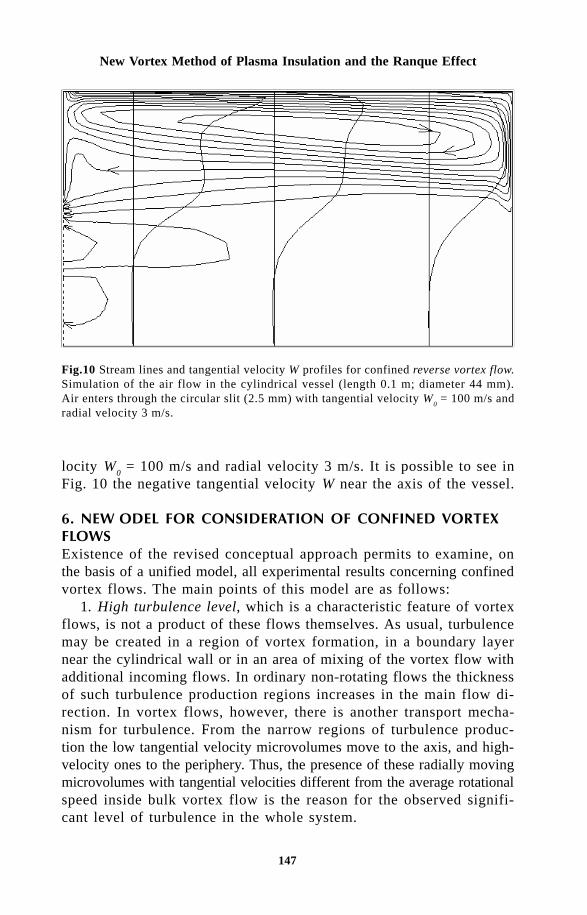
147
New Vortex Method of Plasma Insulation and the Ranque Effect
Fig.10 Stream lines and tangential velocity W profiles for confined reverse vortex flow.Simulation of the air flow in the cylindrical vessel (length 0.1 m; diameter 44 mm).Air enters through the circular slit (2.5 mm) with tangential velocity W
0 = 100 m/s and
radial velocity 3 m/s.
locity W0 = 100 m/s and radial velocity 3 m/s. It is possible to see in
Fig. 10 the negative tangential velocity W near the axis of the vessel.
/)' ,!$&,!,#,')$Existence of the revised conceptual approach permits to examine, onthe basis of a unified model, all experimental results concerning confinedvortex flows. The main points of this model are as follows:
1. High turbulence level, which is a characteristic feature of vortexflows, is not a product of these flows themselves. As usual, turbulencemay be created in a region of vortex formation, in a boundary layernear the cylindrical wall or in an area of mixing of the vortex flow withadditional incoming flows. In ordinary non-rotating flows the thicknessof such turbulence production regions increases in the main flow di-rection. In vortex flows, however, there is another transport mecha-nism for turbulence. From the narrow regions of turbulence produc-tion the low tangential velocity microvolumes move to the axis, and high-velocity ones to the periphery. Thus, the presence of these radially movingmicrovolumes with tangential velocities different from the average rotationalspeed inside bulk vortex flow is the reason for the observed signifi-cant level of turbulence in the whole system.
148
Thermal Plasma Torches and Technologies
2. The main specific features of vortex flows in different deviceslike heat exchange intensification or the apparently contradictory ef-fect of laminarization of flames [8] are associated with the presenceof recirculation zones. The number and shape of such zones (for example,see Figures 4, 5, 6 and 10) and the direction of gas circulation in themdepend critically on the inlet conditions, wall roughness and system geometry.So, utilization of the usual integral characteristics of vortex flows suchas the swirl number is often not sufficient to describe the main featuresof these flows, especially with counterflow geometry.
0 $! $$As it was shown changing the location of the vortex inlet to the exitend of the plasma torch leads to a significant decrease of the heat losses.A new method of reducing the harmful influence of the reaction zoneon the surrounding area and, first of all, on the device walls [5] is basedon such simple design modifications. The unwanted influence may, forinstance, be due to the high temperature or high corrosion activity ofthe plasma, flame or reaction products formed in plasma generatorsor in combustion chambers. It may also be necessary to preventcontamination of high purity products caused by partial melting, evaporationor dissolution of the chemical reactor walls. The basic principle of themethod [5] is to locate the reaction products outlet at the axis in thesame end of the reactor as the pipe shaped inlet of the reactants and,i.e. on the inside of this pipe shaped inlet. When the flow direction ofthe products is opposite to the initial flow of the reactants then no significantrecirculation zone is formed inside the reactor. This method is promisingfor energy saving (for example in gas-fired metallurgical furnaces, domesticgas heaters and plasma torches), for protecting the environment(laminarization of combustion should lead to a decreased CO and NO
x
production), for designing new simplified devices (for example, combustorsof jet engines or plasma torches with uncooled walls). New approachfor consideration of the confined vortex flows may give new practicalresults in increasing the efficiency of various “cold” devices: vortextubes for gas cooling and gas separation, dust cleaning cyclones, chemicalreactors, etc.
1 !!' $Simple design modification of vortex stabilization system leads to a significantdecrease of the heat flux to the walls of plasma torches (from 30%to 5% for microwave plasma). This result is in contradiction with traditionaltheory of the Ranque effect, but is in good agreement with the newsimple explanation of the energy separation in vortex tubes described

149
New Vortex Method of Plasma Insulation and the Ranque Effect
here. Advanced numerical simulation methods permit reliable predictionsof heat losses in plasma torches with conventional as well as reversevortex flows stabilization. Experimental investigations and numericalsimulations show that reverse vortex systems are very promising forvarious plasma-chemical processes and other technical applications ofdifferent types of plasma devices (non-transferred arcs, RF inductionand MW plasma torches) as well as for gas burners.
AcknowledgmentsThis cooperative work was made possible by financial support from The ResearchCouncil of Norway in the frame of The Nordic Scholarship Scheme for TheBaltic Countries and Northwest Russia.
References1 A.F. Gutsol, Khimiya vysokikh energiy (High Energy Chemistry), 29 No.5,
373-376 (1995).2 A.F. Gutsol and V.T. Kalinnikov, Zhurnal prikladnoy khimii (Russian J.
of Appl. Chem.), 68, No 6, 885-891 (1995).3 A.F. Gutsol, In: Using of the reverse flows for insulation of the inter-
action zones and qualitative interpretation of the Ranque effect. Chemistryand technology of processing of complex raw materials of Kola Pe-ninsula, Apatity, KSC of RAS (1996), pp.68-71.
4 V.T. Kalinnikov and A.F. Gutsol, Doklady Akademii Nauk. (Proceedingsof the Russian Academy of Sciences, Technical Physics), 353, No.4,469-471 (1997).
5 A.F. Gutsol, Method for the flow system formation. Notice of Allowanceof 1 July 1996 on the Russian Patent Application No 95112323.
6 A.P. Merkulov, The Vortex Effect and Its Application in Engineering (inRussian), Mashinostroenie, Moscow (1969), p.184 p.
7 A.K. Gupta, et al, In: Swirl flows, Abacus Press, England (1984).8 N.A. Chigier, et al, Comb. and Flame, 14, 171-180 (1970).9 A.F. Gutsol, Uspekhi fizicheskikh Nauk (Russian Physics - Uspekhi),
167 (6), 665-687 (1997).1 0 J.M. Nash, In: Vortex Expansion Devices for High Temperature Cryo-
genics. Proceedings of the 26th Intersociety Energy Conversion EngineeringConference (IECEC-91),Boston, Massachusetts (1991). Publ. By AmericanNuclear Society, USA, Illinois, La Grange Park. Vol.4, pp.521-525.
11 L.M. Dyskin, In: Energetic separation in rotated gas flow, Izvestiya Vuzov.Stroitel’stvo (Proceedings of Higher School. Building), No.11 (1995),pp.116-118.
1 2 S.V. Patankar, et al, J. Fluid Mech., 62 (3), 539-551 (1974).1 3 M.P. Arnal, et al, Int. J. Heat and Fluid Flow, 13, No.4, 347-357.1 4 S.V. Patankar, et al, J. Fluid Mech., 67(3), 583-595 (1974).1 5 V.E. Fin’ko V.E. Zhurnal tekhnicheskoy fiziki (Russ. Journal of Tech-
nical Physics), 53 (9), 1770-1176 (1983).1 6 G.N. Abramovich and R.S. Trofimov, Inzhenerno-Fizicheskiy Zhurnal (Jour-
nal of Engineering Physics and Thermophysics), 53 (5), 751-757 (1987).

150
Thermal Plasma Torches and Technologies
Cherednichenko V.S., Zagorskii A.B., Pavlenko L.K.
Vacuum hollow cathode arc dischargers allow extremely high heat fluxesto be produced on heated surfaces (up to 107 W/m2) at low workingvoltages (30÷100 V). These arc discharges are favoured in appropriateindustries because of their high efficiency (up to 80–90%) in a rangeof pressure from 1 to 103 Pa.
The basic design of an arc discharge is a tube with the inner di-ameter R and working gas being fed through it into the low pressurechamber. The open end of the tube is directed to the anode. The lengthof the cathode tube is several inner diameters of the tube. There arefour main working regimes of hollow arc discharge being distinguishedby the magnitudes of plasma gas flow rate G, pressure P in a vacuumchamber and discharge current j : 1) normal regime 2) low flow rateof plasma gas regime, 3) low current regime and 4) high pressure re-gime. The normal regime is of the greatest interest for its applicationsin plasma technologies so the latter one was thoroughly investigated inthe present paper.
While investigating the high current arc in a 500 kW facility, a dischargewas burnt between a hollow tantalum cathode and a flat anode. The latterone represents itself a metal in a mould. At the normal regime at thecurrent of up to 300 A the plasma column in the space between the cathodeand the anode had the diffused bell-shaped form. The plasma columnbecomes clear, sharp bounded with the visible diameter approximatelyequal to the cavity diameter. The sharp space stabilization of the plasmacolumn shows the leading role of gas-dynamics features of the plasmagas flow through the hollow cathode and the great influence of dischargecurrent’s own magnetic field on the processes behavior of different kinds
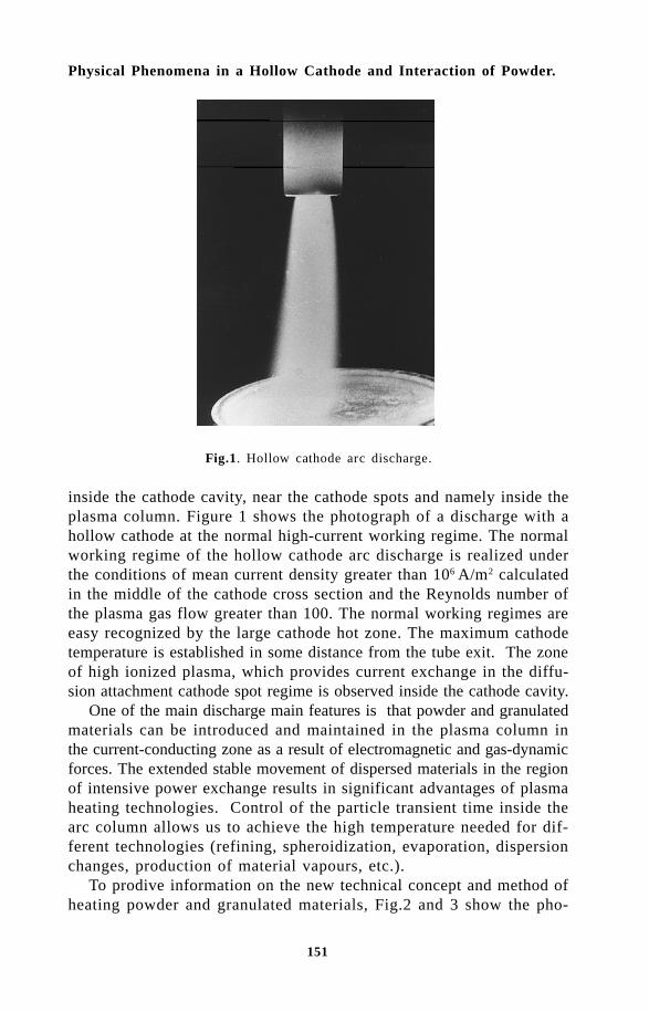
151
Physical Phenomena in a Hollow Cathode and Interaction of Powder.
Fig.1. Hollow cathode arc discharge.
inside the cathode cavity, near the cathode spots and namely inside theplasma column. Figure 1 shows the photograph of a discharge with ahollow cathode at the normal high-current working regime. The normalworking regime of the hollow cathode arc discharge is realized underthe conditions of mean current density greater than 106 A/m2 calculatedin the middle of the cathode cross section and the Reynolds number ofthe plasma gas flow greater than 100. The normal working regimes areeasy recognized by the large cathode hot zone. The maximum cathodetemperature is established in some distance from the tube exit. The zoneof high ionized plasma, which provides current exchange in the diffu-sion attachment cathode spot regime is observed inside the cathode cavity.
One of the main discharge main features is that powder and granulatedmaterials can be introduced and maintained in the plasma column inthe current-conducting zone as a result of electromagnetic and gas-dynamicforces. The extended stable movement of dispersed materials in the regionof intensive power exchange results in significant advantages of plasmaheating technologies. Control of the particle transient time inside thearc column allows us to achieve the high temperature needed for dif-ferent technologies (refining, spheroidization, evaporation, dispersionchanges, production of material vapours, etc.).
To prodive information on the new technical concept and method ofheating powder and granulated materials, Fig.2 and 3 show the pho-

152
Thermal Plasma Torches and Technologies
Fig.2. Photo of hollow cathode plasma arc discharge through blue optic filter withtransparent band of 350 nm to 450 nm.
Fig.3. Photograph of hollow cathode plasma arc discharge through red optic filterwith transparent bend of 550 nm to 650 nm.
tograph of a hollow cathode vacuum plasma discharge with the sameparameters as the one in Fig.1: current is 1000 A, voltage 35 V, plasmagas is argon, working pressure is 1.73 Pa, consumption of powder (tantalum)is 3 × 10⁻⁴ kg/s (1 kg/h). The photograph presented in Fig.2 was made

153
Physical Phenomena in a Hollow Cathode and Interaction of Powder.
through a blue optical filter transparent in the light wavelength rangefrom 0.35 mm to 0.45 mm, and the photograph in Fig.3 was producedusing a red optical filter with a transmission band from 0.55 mm to0.65 mm. The tantalum powder, fraction 20 to 60 µm, was inserted intothe central part of the plasma column, is clearly shown there.
The powdered materials are held in stable manner inside the vacuumplasma column and are heated up to the melting point and higher asa result of interaction with hot plasma. The main well known advan-tages of plasma heating can be fully realized in such devices. Specialdesign of vacuum arc plasma heaters with a hollow cathode, its highpower level (100–600 kW) achieved now allow plasma advance tech-nologies to be realised on a principally new ground in a wide range ofworking parameters (pressure, temperature) in order to solve techno-logical problems (maximum heat flux on particle’s surface reaches 107-108 W/m2). The interaction between powder and plasma’s own magneticfield prevents powder loses even for single particles so 100% processingefficiency is reached.
Due to these unique features, it has become possible to carry outon the industrial scale treatment of dispersed materials directly in thehot plasma flow where they can be heated to the melting point, trans-formed to the vapour phase, ionized and produce plasma flows of treatedmaterials (both metals and nonmetals). The developed heating systemallows us to perform not only refining and reducing but also spheroidizationand changes of the dispersion of powders, producing pure vapors andplasma jet flows for the plasma-chemicals reactions where the treatedmaterials are efficiently transformed to commercial products or are usedfor surface coating. Various gases can be used to organize processesin dissociated or ionized media. The special structure of the plasma columnand the gases existing there in different phases create appropriate fa-vourable conditions for unique chemical reactions to run in directionsnot possible under the normal conditions. Thus, all the peculiarities ofplasma interactions with the treated materials should be taken into accountwhen examining the problems of treatment of powder materials in vacuumplasma for any business plans concerning electro-technology processes.
!" #The plasma gas fed into the cathode tube supports the diffusion cathodespot. The cathode temperature is self-adjusted by its interaction withthe highly ionized plasma. For the cathode system with the thermal electronsemitted by the cathode, with the ion current and back electron currentbeing taken into account, the charge and energy conservation equationscan be written respectively as follows

154
Thermal Plasma Torches and Technologies
j j j jem i oe+ − = (1)
j T j T q ji e k oe e r em⋅ ⋅ + − + + ⋅ ⋅ + = + ⋅( ) ( )2 2ϕ χΦ Φ Φ (2)
where qr is the surface radiation flux; ϕ
k, Φ are the absolute values of
the cathode sheath potential drop and emission energy respectively; χis the ionizing potential of the plasma gas; T
e is the electron temperature
(eV). The current density and radiation flux are given by [1]:
j e ne T
Mie= ⋅ ⋅ ⋅
1
2
1
2; j k A T eem k
e
kTk= ⋅ ⋅−
12
Φ (3)
where n is the volume concentration of charged particles, α is the ionizingcoefficient, T
k is the temperature of the cathode surface, K. Since the
given analysis is of the qualitative nature, the Schottky’s correction inthe second equation of system (3) is omitted. The coefficients k
1, k
2 have
the order of unity and take into account the possible influence of theouter cathode surface.
The energy conservation equation on the inner side of a hollow cathodewith the system of equations (3) taken into consideration can beexpressed in a following form:
j T TM
me
k T k A T e
i e k ee
T
k k
e
k T
k
e
k
⋅ ⋅ + − + + ⋅ ⋅ + ⋅ ⋅⋅
⋅ =
= ⋅ ⋅ ⋅ + ⋅ ⋅ ⋅ ⋅
−
− ⋅⋅
[ ( ) ]2 22
1
2
14
22
ϕ χ απ
ε σ
ϕ
Φ Φ
ΦΦ (4)
Numerical analysis of equation (4) enables the dependence the of cathodesheath potential drop ϕ
k on cathode temperature T
k to be determined and
is presented in Fig.4. The state of point (ϕk*, T*) on the curve is de-
termined by the minimization of the left side of equation (4) with re-spect to the potential ϕ :
If one takes argon as the plasma forming gas, the approximate valueof ϕ
k* will be ϕ
k*≈ 5.5×T
e . The temperature T* relates to the region
of the start of intense thermal emission. The temperature T1 corresponds
to the maximum possible level of the back electron flux to the cath-

155
Physical Phenomena in a Hollow Cathode and Interaction of Powder.
Fig.4. Variation of cathode sheath potential drop versus cathode temperature in anactive zone.
ode at ϕk= 0. For the point (ϕ
k*, T*), equation (4) becomes:
12
3
12 4
22
1n
eT
MT k T k A T ee
k k
e
k Te k
k
+ − + = ⋅ ⋅ +− ⋅
⋅( )*ϕ χ ε σΦ ΦΦ
(5)
with the next condition being satisfied
jj T
Toei e
e
=⋅
⋅ +2 Φ
The net result of approximate qualitative solution of equation (4) indicatesthat for every cathode temperature there are two regimes which essentiallydiffer by their cathode discharge mechanism. It is obvious that the uppercurve of solution (4) corresponds to the ascending (stable) branch ofthe volt–ampere characteristic of the cathode sheath (dϕ
k / dj > 0) and
that the lower curve of this solution corresponds to descending one (whichneeds additional stabilization). In the steady state, the total heat fluxon the cathode surface is equal to zero (qΣ
= 0). For the upper dependencein Fig.4. the inequality dqΣ / dT
k < 0 holds and dqΣ / dT
k > 0 for the

156
Thermal Plasma Torches and Technologies
lower one respectively. Therefore, the upper branch of solution (4) isstable in the electrical and energy sense. When ϕ
k becomes less than
ϕk*, the discharge linkage in the hollow cathode transforms from its diffusion
form to contracted form so the cathode temperature approaches to T1
(or the melting point of cathode material if it is lower than T1). From
the Steenbeck’s minimal voltage principle point of view, the stable dischargewill be situated closest to point (ϕ
k*, T*) so the voltage drop for the
considered hollow cathodes with the characteristic value of Te will be
of the order of 25–40 V. This range of the working cathode voltage dropis with observed in experiments. When low-current regimes with the voltageapproaching the above-mentioned minimum threshold are used in industrialarc plasma torches with the hollow cathode, unstable voltage pulsat-ing discharges occur (switching to the low characteristic regime in Fig.4).The analogous discharge behavior is observed when the plasma gas flowrate decreases for specific working current because of the decrease ofconcentration n. Thus, it can be proposed that for every definite minimumgas flow rate (i.e. for definite concentration of n) there is minimum cathodetemperature T* below which the stationary discharge changes to unstableform. Numerical assessment of the current conservation law shows thatthe ion current and back electron current are of the same order nearthe critical point (ϕ
k*, T*).
The qualitative analysis of discharge processes inside the hollow cathodepresented above is in good agreement with the available experimentaldata [2,3].
It should be noted that all the assessments being made depend onlyslightly on the assumptions regarding the cathode temperature and emissionenergy (or even specific emission mechanism).
$% #" !To solve the heat transfer and heat balance problem for the particlesin plasma with sharply differing temperatures of electrons, ions and neutralcomponents, the particle is usually considered as a probe whose potentialis determined from the condition of total current being equal to zero(floating potential). Using this approach for high-pressure plasma, theauthors of Ref. 4 derived the governing equations for the heat flux onthe surface of a particle 1 µm in size taking into account the energyloss on in evaporation of particle’s material and radiation exchange betweenplasma and the particle. Heating of submicron particles was studied in[5] where it was found out that both the temperature of the particle andplasma temperature strongly influence the absorption of plasma radiationdue to the effect of the particle size. These investigations were continuedin [6] where the heat flux on the particle surface was determined separately

157
Physical Phenomena in a Hollow Cathode and Interaction of Powder.
for ions, electrons and neutral molecules. In all these papers, the energydistribution function for all plasma components was assumed to beMaxwellian, i.e. equilibrium, although it is well known that the particlescause perturbation in plasma associated with the recombination of ionson the surface and with the presence of negative charge on the particle.If the negative potential is high enough, the electron distribution functioncan be considered to be equilibrium to a first approximation since alarge part of electrons are reflected from the particle. However, thedistribution function of the ions in the vicinity of the particle can greatlydiffer from Maxwellian one so the calculations carried out on this basismay lead to large errors when calculating the heat flux. The nonequilibriumion distribution function can be derived from a set of appropriate kineticand electrodynamic equations [7]. It is a very complex problem to findout the heat flux by such sophisticated approach; it is linked with solvingthe Poisson equation whose right part in integral manner on the requiredpotential. In this connection, it is eseential to investigate initially theproblem in a simplified approach assuming the equilibrium electrondistribution function, as carried out by many authors [4–6]. In the presentpaper, the results of electric probe theory, which considers the plasmadistortion caused by the particles, are also used during the calculationof the ion flux on the particle.
The formulated problem will be investigated under the following initialassumptions: plasma is assumed to be two-component and fully ionized(it is proved in [8] that all neutral components are forced out from theplasma column); it is a steady state problem without any oscillationsand relaxation processes; it is the problem of a single particle in uni-form plasma. In the steady state regime, the particle has negative chargebecause of the difference between thermal velocities of electrons andions (the total charge current to the particle is equal to zero).
It is shown by analysis of heating of a small spherical particle thatthe thermoemission current comparable with the ion one appears at sometemperature threshold. This current has a strong influence on the to-tal particle heat flux. So the problem of heating of the particle will besolved in two stages: 1) the total heat flux on the spherical particle willbe calculated without thermal emission current taken into account (lowtemperature regime); 2) the accuracy of the results received in the firststep will be improved by taking into account the thermal emission current.This approach allows us to distinguish sharply the effect of differentfactors on the process of heating the spherical particles in the plasmaflow.
Let us estimate individual contributions to the total heat flux withspecial reference to heating of a spherical particle argon plasma of a
158
Thermal Plasma Torches and Technologies
hollow cathode arc discharge with electron and ion temperatures beingequal approximately to T
e ~ 5–10 eV and T
i ~1 eV. The ionization potential
is taken to be equal to χ = 15.8 eV. Under the conditions accepted here,in analysis of the ions their thermal energy can be neglected in com-parison with the recombination energy. In the plasma with the parametersmentioned above, the spherical particle acquires potential ϕ
p which is
equal to –20 V. It is therefore necessary to consider the contributionof the kinetic energy, equal to e × V, where V = –ϕ
p, acquired by the
ion in the particle field. Thus, every ion and every electron bring re-spectively the following energy to the particle ε
i = χ + e×V, ε
e =
2kTe. Moreover, the energy equal to the work function of the electron
is generated during absorption of the electron by the particle surface.The same quantity of energy is also spent during the recombination ofthe ion on the particle surface.
In the model being analyzed, it is considered all the ions hitting particleare recombined and the electrons are absorbed. This feature leads todisappearance of the ions reflected from the spherical particle and,consequently, the Maxwellian distribution function of ions is distortedand a large difference appears. The high negative potential of the probeparticle which is raised up to –20 V causes a large part of the elec-trons to reflect from it. Therefore, as accepted in the probe theory [9],the energy distribution function of electrons will be assumed to beMaxwellian. In such circumstances, only those electrons whose energyis high enough to overcome the potential barrier will hit the surface ofthe spherical probe particle. This key point condition allows us to calculatethe values of electron current and electron heat flux on the sphere re-spectively:
= ⋅ ⋅⋅
⋅ ⋅⋅
−
π (6)
( )
= ⋅⋅
⋅ ⋅⋅ ⋅ ⋅ + ⋅
−
πΦ (7)
To close this problem, it is necessary to obtain expressions identi-cal with (6) and (7) for the ion component.
Since the ion energy distribution strongly differs from the Maxwellianone, this problem is more complicated. There are many models for calculatingthe current of charged particles attracted by the probe. A detailed re-
159
Physical Phenomena in a Hollow Cathode and Interaction of Powder.
view can be found in [9]. All of these models include diffirent aprioriassumptions concerning the ion energy distribution and the potential ofthe plasma area polarized by the probe. These models give similar valuesof the charge particle current on the probe. Let us consider the Allen-Bohm model [10] which is easier to understand.
It is known that the Allen–Bohm model is valid when R >> rD (R
is the particle radius, rD is Debye’s radius). On the other hand, the condition
lj
>> R should be fulfilled for collisionless plasma (lj is the mean free
path length). Consequently, the Allen–Bohm model is valid whenl
j >> R > > r
D. The analysis of [9,10] shows that this condition is ful-
filled for the 10...40 µm diameter particles inside the vacuum plasmaof the hollow cathode arc. Therefore, the Allen–Bohm model may beused to determine the ion current. The calculation of the ion flux tothe sphere (the probe) is carried under the following assumptions. SinceT
e >> T
i, the ion temperature is neglegted; ions are in the state of rest
far from the particle; the ion movement is only radial due to the sphericalsymmetry of the electric field; collisions and ionization are absent sothe total flow on the sphere does not change; plasma is quasineutral.These suppositions allow us to receive the following expressions for ioncurrent and ion heat flux on the sphere:
= ⋅ ⋅ ⋅
⋅
(8)
( )
= ⋅ ⋅⋅
⋅ ⋅ + −
χ Φ (9)
where M is the ion mass of the plasma gas.In the expressions (6), (7), (9), the potential of the sphere is still
an unknown function. It may be calculated from the condition of to-tal current on the sphere being equal to zero, so equating the expres-sions (6) and (8), one can solve them in respect of the potential
=− = ⋅
⋅⋅
⋅⋅
ϕ
π
(10)
The total heat flux on a ‘cold’ sphere of the probe particle will be

160
Thermal Plasma Torches and Technologies
= + = ⋅ ⋅
⋅⋅ + ⋅ ⋅ ⋅
⋅⋅
+ ⋅ ⋅
χ
π (11)
The two first terms in the parentheses of (11) represent the contri-bution to the ion heat flux, the third one 2×k×T
e is the electron com-
ponent of the total heat flux. Regardless of the relatively low electroncontribution to the total heat flux (in argon plasma, for example, withT
e ~ 5 eV and the cold particle regime its part is approximately 25%)
the latter one depends strongly namely on its temperature. This is linked,firstly, with the fact that electron temperature j
i ~ k×T
e in the Allen-
Bome model has a strong effect on ion current and, secondly, that theelectron temperature also affects the ion energy acquired by the ion inthe particle field. Such current and potential behavior was examinedin details, for example, in [1]. Thus, analysis of expression (11) showsthat the properties of the plasma gas (χ, M) and the temperature of electronsT
e are the main parameters which can be used to control the total heat
flux on the particle.Expression (11) was derived on the basis of the assumption that electro-
dynamic and thermal processes which take place during sphere heat-ing are not linked together. This kind of process separation is possi-ble only when the thermoemission current from the sphere can be ne-glected comparing to the ion current. This approach to examining theheat processes is suitable for the treatment of metallic powders withlow melting points. On the other hand, when treating the high-meltingmetals such approach will be wrong and it is impossible to neglect thethermoemission current.
The presence or absence of the thermoemossion current from thesphere changes the total heat flux through the value of the floatingpotential. If thermoemission current is absent (cold sphere), the floatingpotential is calculated from expression (10); if thermoemission currentis present (hot sphere) the value ϕ
p obtained by solving the current
conservation equation on the sphere surface:
+ − = (12)
where ji, j
em, j
e are the current densities of ion, thermoemission and
electrons, respectively.In order to calculate the total heat flux on the sphere in the pres-
ence of thermoemission current, let us consider that all the electronsemitted by the hot sphere are absorbed by the plasma. This suggestion

161
Physical Phenomena in a Hollow Cathode and Interaction of Powder.
allows us to rewrite the expression (12) as follows:
⋅ ⋅ ⋅
⋅+ ⋅ ⋅ − ⋅ ⋅
⋅⋅ ⋅
⋅ =− −
Φ
π (13)
where T is the temperature of the particle, A is the thermoemissioncoefficient. When writing expression (13), it is assumed that thethermoemission current is never switched off (potential distribution inthe close vicinity of particle’s surface is supposed to be monotonic).The reasons which can cause the violation of this condition were analyzedin detail in [12].
The relationship for the sphere particle potential with termoemissioncurrent on its surface being taken into consideration is obtained out from(13):
ϕπ
π
=⋅
⋅⋅⋅
+⋅ ⋅
⋅ ⋅⋅
⋅ ⋅
−
Φ
(14)
Writing now the heat flux expression for the ‘hot’ particle, disre-garding the energy being taken away by thermoemission electrons (e
e~
2kT ~ 0.3 eV), gives:
= ⋅ ⋅⋅
+ ⋅ ⋅ ⋅⋅⋅
+ ⋅ ⋅ −
χ
π
− ⋅ ⋅ + ⋅⋅ ⋅
⋅ ⋅⋅
+ ⋅⋅ ⋅
⋅ ⋅⋅
⋅ ⋅
− −
Φ Φ
(15)
where the first three terms (upper line of a formula) coincide with (11).The negative sign of the fourth term in the formula is linked with thedecrease of the particle potential and, consequently, with the decreaseof the ion kinetic energy acquired in the electric field of the particle.This small logarithmic decrease of the heat flux is compensated by the

162
Thermal Plasma Torches and Technologies
linear increase of the number of back electrons in the plasma collidingwith the sphere. The latter fact is explained the decrease of the potentialof the particle with increasing thermoemission current. With the accuracyto the terms of the first order with respecto j
em/j
i, the expression (15)
may be rewritten in the form which clearly illustrates the influence ofthermoemission current:
= + ⋅ ⋅ ⋅ ⋅
−
Φ
where q0 is the heat flux value according to (11).
For clearer representation of the conditions under which the effectof the thermoemission current on the floating potential must be takeninto account, let us rewrite (9) as follows:
ϕ
=
⋅⋅ +
where j e n k T me e e0 2= ¥ / p is the electron current density on the particle
with zero potential. Transforming the last expression assuming that theparticle’s floating potential under the condition of zero thermoemissioncurrent is determined only by the relationship between the ion and electroncurrents:
ϕ ϕ δϕ
= + +
= +
where ( )ϕ
= ⋅ ⋅ is the particle’s potential withoutthermoemission; δϕ =k T
e/e ln (1 + j
em/j
i) is the correction which takes
into account the thermoemission current influence on the potential. Letus estimate the relationship between the thermoemission current densityand ion current density for different materials during their heating upto melting points in a low pressure plasma flow with the parametersdetermined by experiments [8]: n
= 1021 m–3, T
e = 4 eV (6.24×10⁻¹⁹ J);
the plasma gas is argon. The calculated data presented in Table 1 showthat the thermoemission current should be taken into consideration ifrefractory materials are treated.

163
Physical Phenomena in a Hollow Cathode and Interaction of Powder.
Fig.5. Calculated distribution of heat flux and floating potential on tantalum particlevs. its temperature.
Figure 5 shows the values of the floating potential and density ofthe heat flux versus the temperature calculated for heating of tantalumpowder under the experimental parameters mentioned above. The strongheat flux increasing on the particle in the vicinity of the melting pointcauses the given influence on treatment of refractory metals. The reasonfor the increas of the heat flux is the decrease of the floating poten-tial on the particle and consequently, increase of the energy being broughton it by the electrons.
The above-mentioned amplified heating effect of tantalum particlesin the plasma flow is observed in modelling experiments and is utilisedin industrial equipment.
While calculating the heat flux according to (15), one has to rememberthat if the decrease of particle’s potential is too large, the appropriateconditions used when deriving this formula are violated. The next pointthat also must be taken into account is that not all thermoemission electronsleave the particle during the large drop of the floating potential as supposed
M aterial ⋅10
–4,
2 m , K j
e (Tm) , A / m
T in 4 .38 60 505 2 .98 ⋅10 – 33
T itanium 3.95 60 1998 260.6
B eryllium 3.92 60 1560 3 .16.10 –1 Z irconium 4.12 330 2133 2768.1
N iobium 3.96 57 2688 1 .54 ⋅105
M olybdenum 4.20 51 2923 2 .49 ⋅105
T anta lum 4.20 55 3223 1 .54 ⋅106
T ungsten 4 .50 75 3689 7 .26 ⋅106
Table 1 Relationship of thermoemission and ion current densities on particles ofdifferent materials at melting points

164
Thermal Plasma Torches and Technologies
when deriving (15). Moreover, the cloud of emitted electrons aroundthe particle may greatly distort not only the field around but also causelarge changes in the distribution functions of ions and electrons whichwere used in calculating the corresponding currents and heat fluxes. Butif the floating potential deviation is small enough, formula (15) depictsthe heat flux change with sufficient accuracy. The assessment of heatingof the finely dispersed tantalum powder, treated in the hollow cathodearc discharge plasma, has shown that according to the heat flux leveldetermined from formula (15), the particles are heated to its meltingpoint 0.15 m from the end of the cathode. This relates to the largestpowder fraction (60 µm) and the maximal velocity of the particles(~ 50 m/s). Calculations were based on the experimental data obtainedin examination of the velocity of the particles in a low-pressure, low-temperature plasma flow [14]. The particles with the fraction smallerthan 60 mm (20–40 µm) and minimum velocity (~ 20 m/s) begin to melt0.02–0.04 m from cathode’s end. More detailed investigation at highthermoemission currents should be based on the exact solutions of kineticequations [7]. Such approach may not only clarify the boundaries ofthe applicability of simple calculation equations but should also helpto reveal all the features of particle heat transfer in the plasma flowunder more intense thermal regimes.
References1. Chen F. Plasma diagnostics . Ed. by R.Hadlstone and S.Leonard (in
Russia).- Mir, Moscow, 1967.2. Cherednichenko V.S., Galkin S.G., Kosinov V.A. Arc plasma flow generation
(in Russia): Institute of Thermophysics, Novosibirsk, 1987, P.306-322.3. Cherednichenko V.S., et al. Thermophysics and Aeromechanics, 1994,
Vol.1, No. 4.4. Uglov A.A., Lokhov U.N., Gnezdovetz A.G. Dokl. Ak. Nauk SSSR, 1979,
V.224, N 2.5. N.N. Rykalin, A.A.Uglov, U.N.Lokhov, A.G.Ghezdovetz (in Russian) Dokl.
Ak. Nauk SSSR, 1979, V.248, N6.6. N.N. Rykalin, A.A.Uglov, U.N.Lokhov, A.G.Ghezdovetz (in Russian) High
temperature Physics, 1981, V.19, N3.7. Cherdnichenko V.S., Zhikharskij A.B. Nauchn. Vestnik NGTU, Novosibirsk,
1995, No.1.8. Cherednichenko V.S., Kosinov V.A. Izv. SO AN SSSR, Ser. Tekhn.
Nauk., 1980, N 13, V.3.9. Kozlov O.V. Electric probe in a plasma (in Russia).- Atomizdat, Moscow,
1969.10. Allen J.E., Boud R.L., Reynolds P. The Proc. of the Phys. Society. Section
B.- 1957, Vol.70, Pt.3, N 447B.11. Alekseev B.V., Kotelnikov V.A. Probe method of plasma diagnostics
(in Russian), Energoatomizdat, Moscow, 1988.12. Cherednichenko V.S., Zhikharskij A.B., Judin V.,S. XI Low tempera-

165
Physical Phenomena in a Hollow Cathode and Interaction of Powder.
ture plasma arc dischargers, Novosibirsk, 1989, Part II.13. Kotelnikov V.A. Inzh.- Fiz. Zh., 1984, V.47, N4.14. Zirjanov S.A. Electric Processing Processes and Systems, Novosibirsk
State Technical University, 1995.
166
Thermal Plasma Torches and Technologies
I.M. Ulanov, S.N. SoldatovInstitute of Thermophysics, Siberian Branch of Russian Academy of Sciences, 630090,Novosibirsk, Russia
Investigations of the induction transformer-type discharge opens up newopportunities for the design of new transformer-type plasma torches,new types of lasers, powerful light sources in visible and ultravioletranges of spectra. The absence of any electrodes and a long service lifeenables the application of plasma torches in continuous large-scaletechnologies. The discharge chamber of a plasma torch can be used notonly for gas heating but as a plasma chemical reactor also. The largelength of the closed induction discharge (about 3–4 meters) providesprolonged contact between gaseous reactants. Thus, the yield of the productcan be magnified.
The use of transparent discharge chamber made from quartz opensup new opportunities for creation of absolutely new light sources.And, at last, the closed discharges of the transformer type may bethe base for the development of new plasma furnaces with low pressure,large diameter and high useful volume; the temperature in heating iseasily variable. These furnaces can find numerous applications in mi-croelectronics.
Unfortunately, the electrodeless induction discharges at frequencies50–20000 Hz with a magnetic core have been studied insufficiently. Thepossibility of developing transformer-type plasma torches was provenin [1–4].
The initiator of studies of induction discharge at frequencies of 60-9600 Hz (with the aim to develop transformer-type plasma torches) wasthe American scientist H. Eckert. In [1], he estimated the current fre-quency and plasma diameter which correspond to the discharge expire
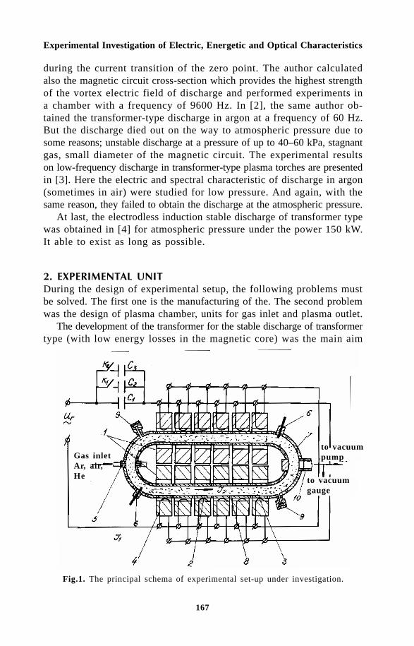
167
Experimental Investigation of Electric, Energetic and Optical Characteristics
during the current transition of the zero point. The author calculatedalso the magnetic circuit cross-section which provides the highest strengthof the vortex electric field of discharge and performed experiments ina chamber with a frequency of 9600 Hz. In [2], the same author ob-tained the transformer-type discharge in argon at a frequency of 60 Hz.But the discharge died out on the way to atmospheric pressure due tosome reasons; unstable discharge at a pressure of up to 40–60 kPa, stagnantgas, small diameter of the magnetic circuit. The experimental resultson low-frequency discharge in transformer-type plasma torches are presentedin [3]. Here the electric and spectral characteristic of discharge in argon(sometimes in air) were studied for low pressure. And again, with thesame reason, they failed to obtain the discharge at the atmospheric pressure.
At last, the electrodless induction stable discharge of transformer typewas obtained in [4] for atmospheric pressure under the power 150 kW.It able to exist as long as possible.
!" #$ %&' During the design of experimental setup, the following problems mustbe solved. The first one is the manufacturing of the. The second problemwas the design of plasma chamber, units for gas inlet and plasma outlet.
The development of the transformer for the stable discharge of transformertype (with low energy losses in the magnetic core) was the main aim
Fig.1. The principal schema of experimental set-up under investigation.
Gas inletAr, air,He
to vacuumpump
to vacuumgauge
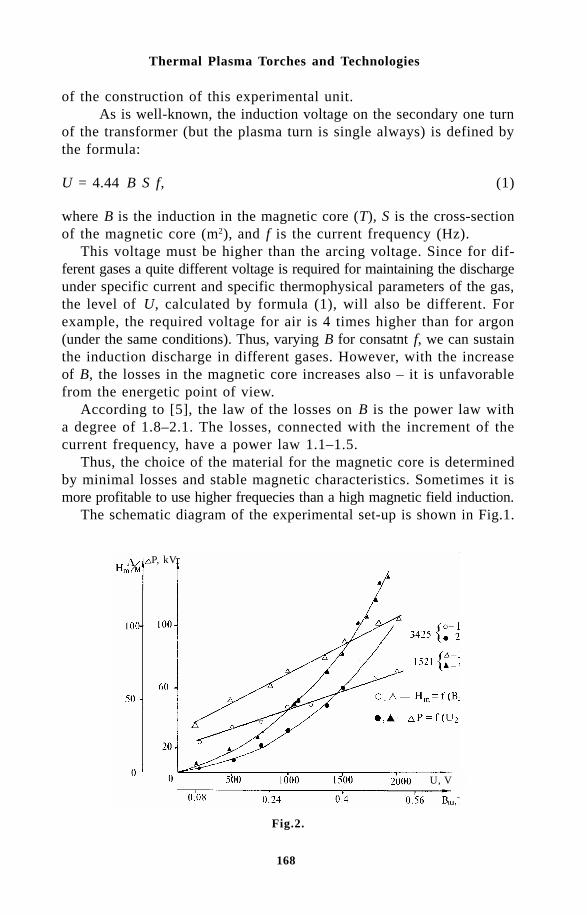
168
Thermal Plasma Torches and Technologies
of the construction of this experimental unit.As is well-known, the induction voltage on the secondary one turn
of the transformer (but the plasma turn is single always) is defined bythe formula:
U = 4.44 B S f, (1)
where B is the induction in the magnetic core (T), S is the cross-sectionof the magnetic core (m2), and f is the current frequency (Hz).
This voltage must be higher than the arcing voltage. Since for dif-ferent gases a quite different voltage is required for maintaining the dischargeunder specific current and specific thermophysical parameters of the gas,the level of U, calculated by formula (1), will also be different. Forexample, the required voltage for air is 4 times higher than for argon(under the same conditions). Thus, varying B for consatnt f, we can sustainthe induction discharge in different gases. However, with the increaseof B, the losses in the magnetic core increases also – it is unfavorablefrom the energetic point of view.
According to [5], the law of the losses on B is the power law witha degree of 1.8–2.1. The losses, connected with the increment of thecurrent frequency, have a power law 1.1–1.5.
Thus, the choice of the material for the magnetic core is determinedby minimal losses and stable magnetic characteristics. Sometimes it ismore profitable to use higher frequecies than a high magnetic field induction.
The schematic diagram of the experimental set-up is shown in Fig.1.
Fig.2.
P, kV
U, V
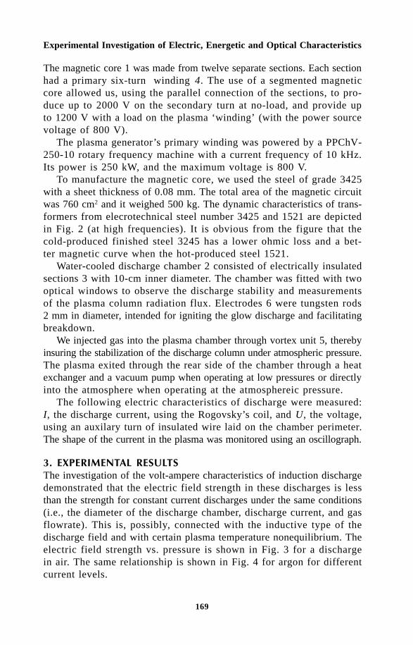
169
Experimental Investigation of Electric, Energetic and Optical Characteristics
The magnetic core 1 was made from twelve separate sections. Each sectionhad a primary six-turn winding 4. The use of a segmented magneticcore allowed us, using the parallel connection of the sections, to pro-duce up to 2000 V on the secondary turn at no-load, and provide upto 1200 V with a load on the plasma ‘winding’ (with the power sourcevoltage of 800 V).
The plasma generator’s primary winding was powered by a PPChV-250-10 rotary frequency machine with a current frequency of 10 kHz.Its power is 250 kW, and the maximum voltage is 800 V.
To manufacture the magnetic core, we used the steel of grade 3425with a sheet thickness of 0.08 mm. The total area of the magnetic circuitwas 760 cm2 and it weighed 500 kg. The dynamic characteristics of trans-formers from elecrotechnical steel number 3425 and 1521 are depictedin Fig. 2 (at high frequencies). It is obvious from the figure that thecold-produced finished steel 3245 has a lower ohmic loss and a bet-ter magnetic curve when the hot-produced steel 1521.
Water-cooled discharge chamber 2 consisted of electrically insulatedsections 3 with 10-cm inner diameter. The chamber was fitted with twooptical windows to observe the discharge stability and measurementsof the plasma column radiation flux. Electrodes 6 were tungsten rods2 mm in diameter, intended for igniting the glow discharge and facilitatingbreakdown.
We injected gas into the plasma chamber through vortex unit 5, therebyinsuring the stabilization of the discharge column under atmospheric pressure.The plasma exited through the rear side of the chamber through a heatexchanger and a vacuum pump when operating at low pressures or directlyinto the atmosphere when operating at the atmosphereic pressure.
The following electric characteristics of discharge were measured:I, the discharge current, using the Rogovsky’s coil, and U, the voltage,using an auxilary turn of insulated wire laid on the chamber perimeter.The shape of the current in the plasma was monitored using an oscillograph.
(" #$ %&' ) ')The investigation of the volt-ampere characteristics of induction dischargedemonstrated that the electric field strength in these discharges is lessthan the strength for constant current discharges under the same conditions(i.e., the diameter of the discharge chamber, discharge current, and gasflowrate). This is, possibly, connected with the inductive type of thedischarge field and with certain plasma temperature nonequilibrium. Theelectric field strength vs. pressure is shown in Fig. 3 for a dischargein air. The same relationship is shown in Fig. 4 for argon for differentcurrent levels.
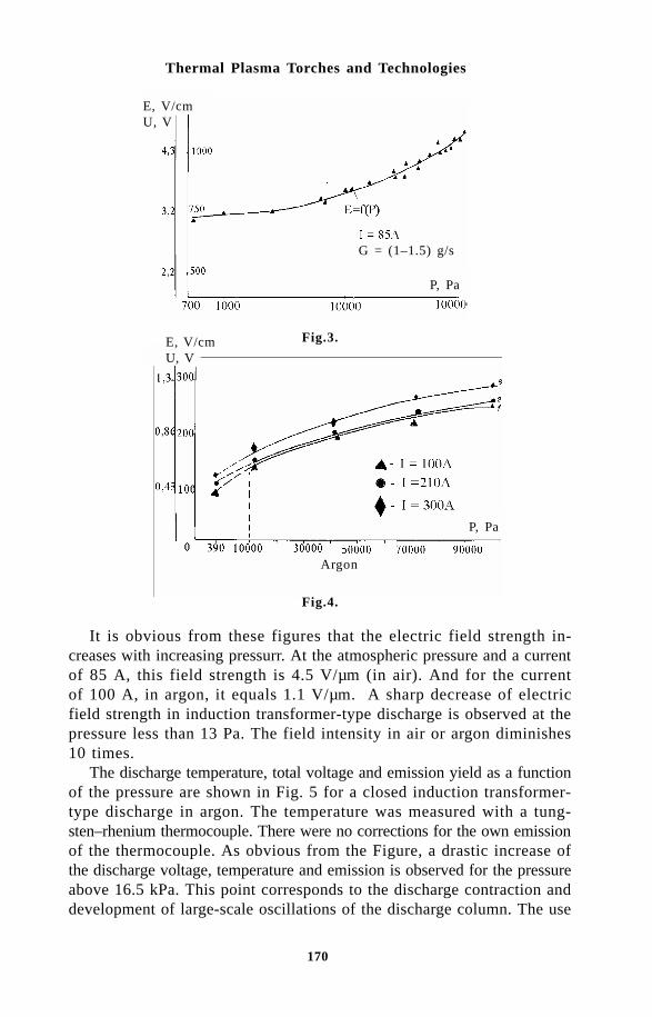
170
Thermal Plasma Torches and Technologies
Fig.3.
Fig.4.
It is obvious from these figures that the electric field strength in-creases with increasing pressurr. At the atmospheric pressure and a currentof 85 A, this field strength is 4.5 V/µm (in air). And for the currentof 100 A, in argon, it equals 1.1 V/µm. A sharp decrease of electricfield strength in induction transformer-type discharge is observed at thepressure less than 13 Pa. The field intensity in air or argon diminishes10 times.
The discharge temperature, total voltage and emission yield as a functionof the pressure are shown in Fig. 5 for a closed induction transformer-type discharge in argon. The temperature was measured with a tung-sten–rhenium thermocouple. There were no corrections for the own emissionof the thermocouple. As obvious from the Figure, a drastic increase ofthe discharge voltage, temperature and emission is observed for the pressureabove 16.5 kPa. This point corresponds to the discharge contraction anddevelopment of large-scale oscillations of the discharge column. The use
E, V/cmU, V
Argon
P, Pa
E, V/cmU, V
P, Pa
G = (1–1.5) g/s

171
Experimental Investigation of Electric, Energetic and Optical Characteristics
Fig.5.
Fig.6.
of vortex stabilization allows a discharge to be generated under higherpressures – up to atmospheric. Without vortex stabilization the dischargegoes out at a pressure above 15–20 kPa. The relationships for the dischargevoltage, gas temperature at the discharge axis and the emission percentageas a function of current are plotted in Fig. 6 (carbon dioxide medium).The volt-ampere characteristic for discharge in argon and air is shownin Fig. 7. The temperature at the discharge chamber axis as a functionof current (argon and air) is plotted in Fig. 8.
The analysis of power losses vs. frequency revealed that best fre-quency range is 20–30 kHz. Further increase of frequency causes higherpower losses.
The measurement of the visible and low-ultraviolet emission yieldwas performed with the optical power gauge IMO-2N. It has a spec-
P, Pa
I, A

172
Thermal Plasma Torches and Technologies
tral sensitive region from 0.33 mm up to 10.6 mm. But for registra-tion in ultraviolet spectra we used FMP-39 device with a region of 0.16-0.6 mm. The visible spectra were cut by light filters BG23 and YB10,and ultraviolet spectra were selected by an UF1 filter. The emission yieldvs. consumed electric power is shown in Fig. 9 for different gases.
Mercury additions into argon enhance the emission yield. When mercuryis added, the yield is 5 times higher for the ultraviolet range and 14times higher for the visible range of spectra. For a consumed electricpower of 11.2 kW, the light yield both in visible and ultraviolet rangeswas 14%. That is, it was about 11 times higher than for a gas dischargein pure argon.
The light yield for the described setup for a discharge in a mercury-argon medium is about 140–170 lm/W. The light flux was measuredby an U116 lux-meter. For comparison, we may note that the light yield
Fig.8.
Fig.7.
E, V/cm
40 Pa
7 Pa
400 Pa
33 Pa
air argon

173
Experimental Investigation of Electric, Energetic and Optical Characteristics
in modern mercury luminescent lamps is up to 85–90 lm/W, this pa-rameter for white-light lamps (40 W) is 110–120 lm/W. The light yieldfor mercury lamps with high and ultrahigh pressure is 45–55 lm/W [6].
Similar investigations were performed with antimony, sulphur, se-lenium and cadmium. The most interesting results were obtained in ex-periments with antimony in argon. Here we observed the lowest elec-tric field strength (0.24 V/cm) and the highest emission yields in vis-ible and ultraviolet regions of spectra. The magnification in the ultravioletregion is 3 times, and in visible region 8 times (in comparison with pureargon).
Specific light blue emission was observed during experiments withsulphur in argon; this testifies the excitation of strong lines of sulphurin the range 0.45–0.55 mm.
' ) )1. The investigation of electric and power characteristics of discharge
on the developed setup indicate that the induction transformer-type dischargewill be used successfully for the construction of high-power transformer-type plasma torches.
2. Powerful stable induction discharge in air and argon was obtainedfor the first time. It was achieved under the atmospheric pressure andcan be used for development of plasma chemical reactors, which uti-lize this type of discharge.
3. The temperature characteristics of induction discharge can be usefulfor the elaboration of plasma furnaces operating in aggressive mediabecause the temperature may be regulated over a wide range by adjustingthe discharge current.
Fig.9.
argon (P = 26.6 Pa)carbon dioxide (P = 8.0 Pa)nitrogen (P = 6.7 Pa)
helium (P = 13.3 Pa)(measurement range 0.33–4.0 µm)
W, kV

174
Thermal Plasma Torches and Technologies
4. The investigation of the optical characteristic of discharge demonstratedthat new light sources can be created on the basis of this kind of dis-charge.
References1. Eckhert, H.U., Plasma generation using gas inductive heating with low-
frequency current, AIAA J., 1971, Vol. 9, P. 1452.2. Eckert, H.U, IEEE Trans. Plasma Sci., 1974, Vol. 2, P. 308.3. Goldfarb, V.M et al., High Temperatures, 1979, Vol. 17, P. 703.4. Kogan, V.A. and Ulanov, I.M., The investigation of the possibility of
developing transformer-type plasma generators, High Temperatures,Vol. 31, No. 1, 1993, P. 95-110.
5. Rusin, Yu. S., Glikman, I.Ya., and Gorsky, A.N., Electronmagnetic Elementsof Radioelectronic Apparatus. Reference Book, Moscow, Radio i Svyaz,1991, P. 225. (In Russian).
6. Reference Book on Light Technique, ed. By Yu. Aizenberg, Moscow,Energoatomizdat, 1983, P. 472. (In Russian).

175
Mathematical Modelling of Transformer Discharge
E.B. Kulumbaev and V.M. LevelkinKyrgyz-Russian Slavic University, Bishkek, 720000, Kyrgyz Republic
The theoretical investigations of the low-frequency discharge of atransformer type without gas flow were carried out. The applicationof the kinless approach with the electrodynamic description of thedischarge and the possibility of a steady approach during calculationof the argon plasma characteristics in the frequency range 1–10 kHzand at pressures of 10-100 kPa was shown. The existence of two regimesof discharge burning was established: stable one with a high temperatureand unstable one with a low temperature. The influence of frequencyand voltage on the plasma coil, type and pressure of plasma gas onthe discharge characteristics was investigated. The results of modellingare in agreement with experiments.
Designations:T - temperature;n - particle concentration;p - pressureϕ – multivalued scalar potential;E, B – vector of the electrical field intensity;E.B – vector of the magnetic field intensity;Φ – magnetic flow;ω = 2πf – a circular frequency;S – heat flow potential;N
e = k
1n
en
a – k
rn2
e n
i – rate of electron generation;
B = 3kmen
ev
e/m
a - the factor of the elastic interaction between electrons
and heavy particles;k
1, k
r – ionisation and recombination factors;
m – particle mass;
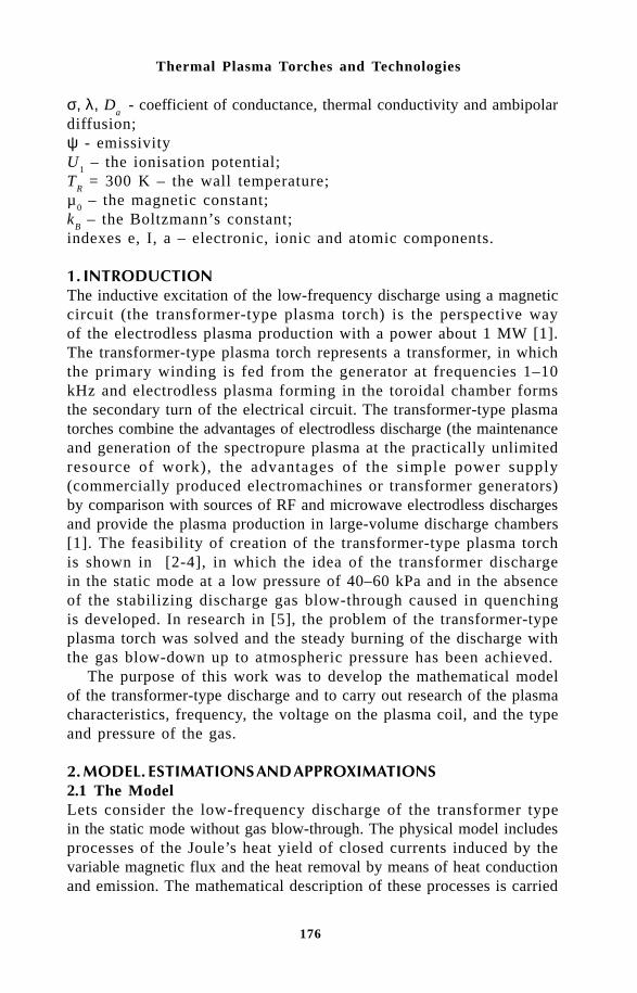
176
Thermal Plasma Torches and Technologies
σ, λ, Da - coefficient of conductance, thermal conductivity and ambipolar
diffusion;ψ - emissivityU
1 – the ionisation potential;
TR = 300 K – the wall temperature;
µ0 – the magnetic constant;
kB – the Boltzmann’s constant;
indexes e, I, a – electronic, ionic and atomic components.
The inductive excitation of the low-frequency discharge using a magneticcircuit (the transformer-type plasma torch) is the perspective wayof the electrodless plasma production with a power about 1 MW [1].The transformer-type plasma torch represents a transformer, in whichthe primary winding is fed from the generator at frequencies 1–10kHz and electrodless plasma forming in the toroidal chamber formsthe secondary turn of the electrical circuit. The transformer-type plasmatorches combine the advantages of electrodless discharge (the maintenanceand generation of the spectropure plasma at the practically unlimitedresource of work), the advantages of the simple power supply(commercially produced electromachines or transformer generators)by comparison with sources of RF and microwave electrodless dischargesand provide the plasma production in large-volume discharge chambers[1]. The feasibility of creation of the transformer-type plasma torchis shown in [2-4], in which the idea of the transformer dischargein the static mode at a low pressure of 40–60 kPa and in the absenceof the stabilizing discharge gas blow-through caused in quenchingis developed. In research in [5], the problem of the transformer-typeplasma torch was solved and the steady burning of the discharge withthe gas blow-down up to atmospheric pressure has been achieved.
The purpose of this work was to develop the mathematical modelof the transformer-type discharge and to carry out research of the plasmacharacteristics, frequency, the voltage on the plasma coil, and the typeand pressure of the gas.
!!" 2.1 The ModelLets consider the low-frequency discharge of the transformer typein the static mode without gas blow-through. The physical model includesprocesses of the Joule’s heat yield of closed currents induced by thevariable magnetic flux and the heat removal by means of heat conductionand emission. The mathematical description of these processes is carried

177
Mathematical Modelling of Transformer Discharge
out in the framework of the two-temperature approximation of plasma[6] and the quasistationary balance equation for the energy of theelectronic gas:
∂∂
λ ψt
n k T T j E B T T U ne B e e e e e
3
2 1
= ∇ ⋅ ∇ + ⋅ − − − −
→ → •
( ) , (1)
the balance equation for the energy of heavy particles:
∂∂
λ∇t
n n k T T B T Ta i B e
3
2+
= ∇ ⋅ + − , (2)
the continuity equation for the electronic gas:
∂∂n
tD n ne
A e e= ∇ ⋅ ∇ +•
, (3)
Maxwell’s equation:
E dld
dtB jm i
→ → → →
⋅ = − + ∇ × =Φ Φ , .µ0 (4)
The system (1–4) is supplemented by Dalton’s law, the quasineutralitycondition, the Ohm’s law and expressions for factors of the two-temperature argon plasma [6].
2.2 The skinless approximation of the electrodynamic modelThe presence of the current in the transformer discharge plasma isconnected to the rotational electrical field E, produced by the variablemagnetic flow Φ
m= Φ
m0 exp(iωt) in the magnetic circuit and by the
variable magnetic flow Φi B d S
→ →
⋅ induced by plasma currents. By
neglecting the primary circuit active resistance for the given frequency,the amplitude Φ
m0 does not depend on the plasma current, whose
demagnetising action is compensated by the growth of the primarycircuit current. For the evaluation of the contribution of the componentof the rotational field E
i created by the variable magnetic field induced

178
Thermal Plasma Torches and Technologies
by the plasma current turn present in the form of the circular currentI with perimeter L
k. The maximum induction of the magnetic field
will be in the ring centre B0 = πµ
0I/L
k. The upper estimate gives the
expression for the magnetic flow through the ring Φi = µ
0IL
k/4. Using
data [5] as ordinary values for the transformer discharge: I = 100 ∏ 300A, L
k >> 2 m, ω = 2π·104 Hz, ωΦ
m0=100 ∏ 1000 V, one can obtain
the ratio of the electrical field components Ei/E >> (ωΦ
i/L
k)/(ωΦ
m0/
Lk)=, ωµ
0IL
k /(4ωΦ
m0) >> 10–2. At T ~ 10 hK the skin layer 2
0/ ωµ σ( )
~15 cm appreciably exceeds the discharge chamber radius Rk
~ 4 cm.Therefore, the skinless approximation is applicable for the descriptionof the transformer discharge electrodynamics and the electrical fieldcirculation differs from zero only for the account of the magneticflow varied in time in the magnetic circuit. The applicability of theassumption had been corroborated by the results of the study. So onecan suppose that in the discharge plasma occupying the two-couplingarea, the equations
∇ × ≈ = −∇ ϕ→ →
E E0,
are true.
Taking into account the Ohm’s law j E→ →
= σ , from the electrical current
continuity equation we may write for the multiple-valued potential
∇ ⋅ =σ∇ ϕ 0. (5a)
The boundary conditions on the surface Σ – the toroidal chamberpartition reduced the two-coupling area given by
ϕ ϕ ϕ∑− ∑+= =0 0 00, , (5b)
The potential jump ϕ0
= iωΦm0
is determined by the speed of themagnetic flux change in the magnetic circuit, so the circulation isequal to
E dl i i tm
→ →
⋅ = − ωΦ ω0 exp( ). (5c)
It should be noted that in the framework of the above assumptions

179
Mathematical Modelling of Transformer Discharge
the electrodynamical model of the transformer discharge is similar tothe model of the electrical arc with electrodes coincided with the sur-face Σ, where one side is the cathode, and the other one is the anode.Consequently, the term ‘the transformer arc’ can be used.
2.3 The stationary approximation of the transformator dischargeIn the low-frequency discharge, the characteristic time of the establishmentof the electrons average energy or temperature t
e is considerably longer
that the period of electric field variation 2π/ω. In this field with theamplitude of approximately A τ
e [7], A = e2 E2
0v
e /2m
e(ω2+v2
e) is the
set up speed of the energy by an electron in the variable electricalfield with the amplitude E
0 averaged over time; τ =1/δ
e; v
e – the frequency
of electron collisions with heavy particles; δ – the average relativepart of the energy transmitted from electrons to heavy particles bycollisions. According to the experiment data [5], for the transformerarc in argon at atmospheric pressure E
0 ~ 1 V/cm. Assuming T
e ≈ 0
kK, δ ≈ 10–4, ve ≈ 1011 Hz, we receive the ratio of the electron energy
amplitude to its average value A τe/(3k
BT
e/2) ≈ 10–3, i.e. the assumption
that the field influence on plasma parameters is small and the plasmacondition may be considered as close to equilibrium is valid.The productof the specific energy yield n
eA into the discharge chamber volume
2πRk
Lk
= 9·10–3 m3 gives the power dissipated in the discharge of110 kW that agrees with the experimental value of ~100 kW. Thethermal sluggishness of the equilibrium plasma is determined throughthe temperature conduction c with a specific time R2
k /c ª 10–1 ∏ 10–2
s it is less than period of the electrical field variation. Then the averagevalues of plasma parameters approximately can be considered asstationary.
Table 1 The calculated in frameworks of non-stationary (averages) and stationarymodels the maximum values of discharge parameters
Model Non-stationary Stationary U2, V
F, kHz
⟨Te⟩, Κ
⟨T⟩ , K
⟨ne⟩ , 1021m–3
⟨I⟩ , kA/m
Te, K
T, K
ne, 1021m–3
I, kA/m
P = 100 kPa 10 8228 8223 2.92 5.29 8227 8222 2.92 5.28 200 1 8240 8235 2.97 5.41 8239 8234 2.97 5.41 10 9081 9081 6.74 15.48 9081 9081 6.74 15.48 300 1 9102 9101 6.99 16.33 9098 9098 7.00 16.30
P = 7 kPa 10 9740 9726 2.72 10.00 9665 9646 2.57 9.78 150 1 9873 9866 3.13 10.92 9920 9907 3.02 10.85 10 10620 10619 5.69 16.77 10609 10607 5.62 16.66 200 1 10729 10726 6.53 18.89 10800 10799 6.59 18.89

180
Thermal Plasma Torches and Technologies
Fig.1 The steady-state temporary dependences of deviations of maximum valuesof the electron temperature ∆T
e = T
e(t) – <T
e>, 103 K (curve 1), the temperatures of
heavy particles ∆T, 103 K (curve 2), the electron concentrations ∆ne/<n
e> (curve
3), the electrical current per unit length I= σEdrr
r
1
2
in the discharge ∆I/<I> (curve
4) as functions of their average per the period of the electrical field intensity variation(curve 5) at p = 7 kPa; f = 10 (a); 1 (b) kHz; U
2 = 150 V.
2.4 Calculated valuationsFor corroboration of the applicability of the considered approximationsand strict numerical valuations, the one-dimensional discharge in thedouble coaxial tube with internal radius r
i and external radius r
2 with
cooled walls has been considered. It was assumed that the magneticflux with the amplitude Φ
m0 was placed in the internal cavity of the
double tube.The system of cylindrical symmetric equations (1–4) with the boundary
conditions R = r1; r
2 : ∂T
e /∂
r = 0; ∂n
e/∂
r = 0; T = T
R was solved by the
numerical method on the basis of the implicit differential four-point procedurehaving stability and monotonic properties.
The calculation of the argon transformer discharge characteristicsfor the experimental [5] data has been carried out: p =7; 100 kPa;f = 1; 10 kHz; r
1 = 0.33 m; r
2 = 0.40
m; and secondary voltage in plasma
U2
= ωΦm0
= 150; 200; 300 V.Figure 1 shows the temporary dependences of deviations of the discharge
parameters from average values (Tab. 1). One can see that at p =7 kPa the amplitude of discharge characteristics oscillations accountsfor less than 10% of their average values. At the atmospheric pressurethese deviations are even smaller, the electron temperature is quasistationaryand other parameters are practically ‘frozen’. The amplitude of the variationof the discharge parameters increases with decrease of the frequency:

181
Mathematical Modelling of Transformer Discharge
Fig.2 Electron temperature, heavy particle temperature, the electrical field intensityand the magnetic field induction as functions of the distance in the argon plasmaat p = 100 kPa, f = 10 kHz, U2 = 200 V.
at p = 100 kPa, f = 0.1 kHz, relative deviations reach ~40%. The averagemaximum values of the parameters slightly differ from the values calculatedin the framework of the stationary model (see Tab.1).
The distributions of the discharge stationary characteristics at p =100 kPa, f = 10 kHz, U
2 = 200 V are presented in Fig.2. Since the electric
field intensity is ~1/r, the scanning effect is not insignificant and it maybe neglected. Separation of the heavy particle temperature from the electrontemperature in the wall layers is appreciable. Temperature equilibriumexists in the central zone.
# $ %3.1 The equilibrium modelTo determine the qualitative features of the transformer type dischargewe considered the one-dimensional discharge whose characteristicsmay be described in the framework of the axially symmetric stationaryenergy balance in the equilibrium plasma, and solutions of Maxwell’sequations (4) by the skinless approximation for the amplitudes of theazimuthal electrical field intensity and the axial magnetic field inductionmay be written as:
− = −
= − =
1 1
2
2
2
0
2
r
d
drr
dS
dr
i
rEdr
E
E Bm
r
r
σ ψ
µωΦ
πσ
,
, . (6)

182
Thermal Plasma Torches and Technologies
The boundary conditions express the thermal equilibrium of the walllayer gas with cold walls and the absence of the magnetic field out-side the double tube (as for the infinitely long solenoid):
r = r1:S = 0; r = r
2: S = 0; B = 0.
The formula for the amplitude of the azimuthal electric field intensityfollows also from the electrodynamic model (5) which potentially is thelinear function of the azimuthal angle in the cylindrical coordinates system.
By introducing a new variable x = ln(r/r1)/ln(r
2/r
1), the energy balance
equation and boundary conditions may be transformed to the form:
− = −
= = = =
d S
dxr
r
r
r
ru S S
x S x S
x2
22
12
1
2
2
1
2
2
0 0 1 0
σ ψ( ) ( )
: , : ,
ln (7)
Here u =ωΦ
πm r
r0 2
14ln .
3.2 The solution without reference to the emissionIgnoring emission (ψ(S) = 0), the task (7) allows the analytical solutionat real transfer properties of plasma. The function S(x) has a maximumin the area 0 < x <1 and satisfies the conditions x = x
m : dS/dx =
0, S = Sm.
With xm and S
m being the subject to determination, the first integral
of equation (7) takes the form of the conservation law
1
2
22 22 2
dS
dxu V S u V Sm
+ =σ σ( ) ( ),
where 2u2Vσ(S)=2u2 σ( ' ) 'S dSS
0 is ‘the potential energy’ being the
monotonic growing function of S. The second integral of equation(7) may be written as
± − =−2u x xm
mS
SdS
V S V Sm
( )'
( ) ( ' ).
σ σ

183
Mathematical Modelling of Transformer Discharge
Here ± is realized in areas 0 < x < xm (dS /dx>0) and x
m<x<1
(dS / dx < 0), respectively. The boundary conditions (7) locate anextremum coordinate x
m = 0.5 and the corresponding maximum value
Sm can be calculated from the relation:
udS
V S V Sm
Sm
=−
σ σ( ) ( ).
0
The integral by additive allocation of the integral function singularityin the top integration limit can be transformed to the form
u dSS
S V S V S S S Sm
m m m m
Sm
= +−
−−
2
1 1
0σ σσ σ( ) ( ) ( ) ( )( ). (8)
Finally, the solution can be written as
dS
V S V S
ux
u xm
S x
x
'
( ) ( ' )
,
( ),
.
.σ σ− − =
≤ ≤
< ≤0
2
2 1
0 0 5
0 5 1
Using the found solution, the electrical characteristics of the dischargeper unit length can be determined: current, power, active resistance
I Edr i V S Q E rdr V S RQ
I V Sm m m a
m
mr
r
r
rl
= = − = = = =σ π σ ωΦ ωΦσ σ
σ
4 20 5 4
22
2
1
2
1
( ), ( ),. ( )
.
To analyse this solution, it is convenient to choose Sm as an exter-
nal parameter with the values of Vσ (Sm) and u at given dependence σ(S).
The parameter u, presenting the complex consisting of the values ω,Φ
mo, r
1, r
2 is the criterion of discharge similarity.
The characteristics of the transformer discharge plasma as functionsof the similarity parameter being proportional to secondary voltage ωΦ
mo
were calculated. The argon and air factors at the atmospheric pressure
were taken from the references in [6]. Calculations show (Fig.3) thatthe contribution of the second term in the right part of (8) may be neglected
and it may be approximately considered that u ≈ 2 S Sm m/ ( )σ . This
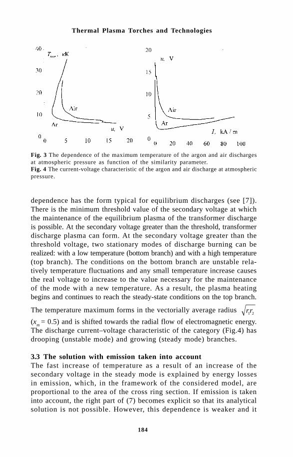
184
Thermal Plasma Torches and Technologies
dependence has the form typical for equilibrium discharges (see [7]).There is the minimum threshold value of the secondary voltage at whichthe maintenance of the equilibrium plasma of the transformer dischargeis possible. At the secondary voltage greater than the threshold, transformerdischarge plasma can form. At the secondary voltage greater than thethreshold voltage, two stationary modes of discharge burning can berealized: with a low temperature (bottom branch) and with a high temperature(top branch). The conditions on the bottom branch are unstable rela-tively temperature fluctuations and any small temperature increase causesthe real voltage to increase to the value necessary for the maintenanceof the mode with a new temperature. As a result, the plasma heatingbegins and continues to reach the steady-state conditions on the top branch.
The temperature maximum forms in the vectorially average radius rr1 2
(xm
= 0.5) and is shifted towards the radial flow of electromagnetic energy.The discharge current–voltage characteristic of the category (Fig.4) hasdrooping (unstable mode) and growing (steady mode) branches.
3.3 The solution with emission taken into accountThe fast increase of temperature as a result of an increase of thesecondary voltage in the steady mode is explained by energy lossesin emission, which, in the framework of the considered model, areproportional to the area of the cross ring section. If emission is takeninto account, the right part of (7) becomes explicit so that its analyticalsolution is not possible. However, this dependence is weaker and it
Fig. 4 The current-voltage characteristic of the argon and air discharge at atmosphericpressure.
Fig. 3 The dependence of the maximum temperature of the argon and air dischargesat atmospheric pressure as function of the similarity parameter.

185
Mathematical Modelling of Transformer Discharge
may be neglected in comparison with the dependence on S. Theassumption has been corroborated by results of the calculations. Denoting
a rr
rl
r
rr
r
r
r
rdx r r
r
r
x x
212 2 2 2
1
2
12 2 2
1
2
10
1 2
22
12 2
1
1
2 1
1
2
1
4= ⋅
=
= −ln ln ln (9)
It is convenient to express values necessary for calculation of r1
andr
2 through the perimeter and by analogy with (8), we receive
u S a S Sm m m≈ +( ( )) / ( ).4 2ψ σ (10)
When emission is taken into account, the parameter u is no longerthe similarity criterion.
It is convenient to express values necessary for calculation r1 and
r2 through the perimeter L
k and the radius R
k of the discharge cham-
ber r1
= Lk/(2π) = R
k; r
2 = L
k/(2π) + R
k.
The calculation results for argon at the atmospheric pressure usingthe data from [5] at L
k = 230 cm, R
k = 3.65 cm, are shown in Figure
5. The account of the emission does not change qualitatively the de-pendence of the maximum temperature on secondary voltage, increaseits threshold value and essentially decrease temperatures values in the
Fig. 5 The dependence of the maximum temperature of argon discharge at atmosphericpressure versus secondary voltage (curve 1 – without considering emission; 2 – withemission taken into account; 3 – the numerical solution).

186
Thermal Plasma Torches and Technologies
steady mode. When Lk ª 2πR
k and assuming that 4S
m<<a2ψ(S
m) from
formulas (9,10) one can receive the approximate expression for the voltageat the plasma turn as a function of maximum discharge temperatureωΦ
mª Lk
2ψ σ( ) / ( )S Sm m
which corresponds to the local balance of Joule’senergy and emission at the discharge chamber perimeter. The values calculatedfrom this formula agree with the top branch of curve 2 of Fig. 5.
3.4 The numerical solutionThe results are shown in Fig. 5. The finite-difference technique permitsa numerical solution only in the steady mode (curve 3 in Fig.5). Thevoltage threshold value at the argon plasma turn at the atmosphericpressure is approximately equal to ~190 V. At smaller values of ωΦ
m0
the simple solution T(r) = TR
= 300 K is independent of the temperaturedistribution defined in the first approximation. Radial distributionsof temperature, electric field intensity and magnetic field inductionat ωΦ
m0 = 200V are similar to the distributions shown in Fig.2. It
should be noted that the equilibrium model slightly overestimates theplasma temperature. The calculated values of the electric field intensity
E > > 0.9 V/cm, and the current I = 2Rk σEdr
r
r
1
2
320 ≈ A axially uniform
at the discharge chamber length for with heat conduction and emissiontaken into account are about equal. At ωΦ
m0 = 300 V, dominant losses
are the emission losses, which represent 80% of dissipated energy.
& %4.1 The three-dimensional modelThe description of the transformer discharge is carried out in theframework of the three-dimensional model. The transformer arccharacteristics are considered in the special orthogonal coordinatessystem in which the flat curve r0 (l) coincident with the dischargechamber axis is chosen as the axis, here l is the length of the axisline measured from any fixed point l = 0 (Fig.6).
The radius-vector of any point of the space is determined as (11).Here v is the unit vector of the main normal to axis r0 (l), β is theunit vector of the binormal; the cross coordinates x and y are distancesfrom the axis measured along the normal and binormal, respectively.The third coordinate is the length of the axial line l.
For the determination of the curvilinear space metrics lets take theincrement of a radius-vector dr from the equation (11) by the accountof Frene-Serre’s formulas
→→→→→

187
Mathematical Modelling of Transformer Discharge
Fig. 6 The diagram of the discharge chamber with the fragment of the cross section.
dr vdx dy kx dl
= + + −β ξ( ) ,1Here k(l) is the curvature of the coordinate axis
r0 (l),
ξ (l)=∂
r0 /∂ l is a unit vector of the tangent line. Hence the square of the lengthelement is equal
dr dr dx dy kx dl
⋅ = + + −2 2 2 21( ) .
In the case of the circular section of the discharge chamber, it is expedientto pass from coordinates x,y to polar coordinates ρ, θ in the plane( v , β ) (Fig.6):
dr dr d d k dl
⋅ = + + −ρ ρ θ ρ θ2 2 2 21( cos ) .
Lame’s factors, corresponding to this metrics Lame’s factor are equalHρ = 1, hθ = r, h
1= 1–k ρ cosθ and permit
equations (1-3, 5a) to be
recorded for the stationary case in the chosen curvilinear coordinatessystem in the following generalized form
10
h h hh h
hh h
h lh h
h lil l
l
Sρ θ
θρ
ρθ
ρ θ∂∂ρ
∂Φ∂ρ
∂∂θ
∂Φ∂θ
∂∂
∂Φ∂
Γ Γ ΓΦ Φ ΦΦ
+
+
+ = . (12)

188
Thermal Plasma Torches and Technologies
Here ΓΦ, SΦ are non-linear factors whose form depends on meaningof variable Φ (Table 2) and are established from correspondence toequations (1–3, 5a).
For the solution of the system of differential elliptical equations (12)the boundary conditions for dependent variables are set for the entirecalculated area limit which, due to the task symmetry, is limited by co-ordinates 0 < l < L, 0 < ρ < R
k, 0 < θ < 2π, where L = L
1 + pR
0/2+L
2.
In input and output sections, symmetry conditions for Φ = Te, T, n
e
and the given potential values give
∂Φ ∂ ϕ ϕ ϕ/ ; , , );l L L1 0 1 0 0 10= = == = =
At the lateral surface of the discharge chamber, the conditions of theelectron normal interface, the given values of heavy particle tempera-ture, the absence of the normal component of the electric field inten-
Table 2 Non-linear factors of the generalized equation (12)
Fig. 7 The influence of current (a) and pressure (b) on electron and heavy particlestemperature distributions in toroidal argon discharge.
Φ ΓΦ S Φ Equation Te λe 0.5 σ E2–B(Te–T)- Ψ
-U1ne
(1)
T λ B(Te–T) (2) ne DA ne (3) ϕ σ 0 (5a)

189
Mathematical Modelling of Transformer Discharge
Fig. 8 The current–voltage characteristic of argon at p = 7 kPa (xxx are experimentaldata [5]).Fig. 9 The dependence of the voltage on the argon plasma turn versus the pressureat I = 300 A (xxx are experimental data [5]).
sity may be written as
Φ = = == =T n T Te e R R Rk K, ; .: /ϕ ∂Φ ∂ρ ρ ρ 0
4.2 The toroidal dischargeFor the toroidal transformer discharge L
1 = L
2 = 0; k(l)=R–1
0 = 2π/
Lk
= const; Φ = Te, T , n
e do not depend on the coordinate l and
equation (12) for the potential has the simple solution ϕ = iU2 (l/
Lk). The electric field intensity is equal
E E Elk
iU
L kρ θ ρ θ= = = −
−0 0 2
1, , ,
( cos )
The geometrical ratio r = R0(1– k ρ cosθ) agrees with (6).
The calculation of two-dimensional characteristics of toroidal argondischarge was carried out for f = 10 kHz; L
k = 230 cm; R
k = 3.65 cm
(experimental datae from [5]).The calculation results are shown in Figs. 7–9. The influence of current
and pressure on the transformer discharge characteristics is similar topatterns established for the electrical arc [6].
As the calculations have shown, the plasma in equilibrium decreasesby increasing a current and a pressure (Fig.7). At pressures less than10 kPa, the separation of electron temperature from heavy particle tem-

190
Thermal Plasma Torches and Technologies
perature is appreciable along the entire cross section of the dischargechamber. At p = 90 kPa, a practically equilibrium discharge core formsand equilibrium is observed in the wall layers. The electron tempera-ture near walls remains at the level ~4 ∏ 5 kK. By increasing the pressurethe tendency to contraction of the transformer arc is becomes more distinctive.
Comparison between the calculated and experimental discharge current-voltage values at p = 7 kPa is shown in Fig. 8. Satisfactory quanti-tative agreement is found between theory and the experiments. The maximumdeviations between the theoretical and the experimental values are atU
2 < 50 V and U
2 > 200 V. The calculated dependence of the second-
ary voltage versus pressure at I = 300 A (Fig.9) only qualitatively repeatsthe experimental one. The quantitative deviations may be explained bythe possible influence of the gas-dynamic characteristics which are nottaken into account in the considered model. At a pressure of p > 40kPa the burning of the transformer arc is possible only under the conditionof the gas-dynamic stabilization of the vortex [5]. From the energy viewpoint,it is obvious that the injecting of cold gas into the discharge chambercauses cooling of the arc. Therefore, for the given current the requiredsecondary voltage (Fig.9) is higher than that required in the static case.
References1 S.V. Dresvin, et al., RF and microwave plasmatrons, Nauka, Novosibrisk
(1992).2 H.U. Eckert, AIAA J. 9, No.8, 1456 (1971).3 N.N. Rikalin, et al., Fiz. Khim. Obrab. Mater., No.4, 1555 (1977).4 V.M. Goldfarb, et al., Termofiz. Vysokikh Temper., 17, No.4, 698 (1979).5 V.A. Kogan and I.M. Ulanov, Termofiz. Vysokikh Temper., 31, No.1,
105 (1993).6 V.S. Engel'sht, et al., The theory of the electric arc column, Nauka,
Novosibirsk (1990).7 Yu.P. Raizer, The physics of gas discharge, Nauka, Moscow (1987).

191
Integrated Method of Research of Processes in ........
O.Y.Novikov and V.F.PutkoSamara State Technical University, 443098, Samara, Galaktionovskaya 141
The 3-rd International Working Meetings was used as a basis forpreparing this article as the review of the results of work of theSamara group, representing one of branches of scientific school ofM.F. Zhukov, the Academician of the Russian Academy of Science,published mainly in published in a series of monographs under theedition of Prof Zhukov [1–4].
The strong effect of the power supply system of plasma units onprocesses proceeding in them is now recognized. These systems are socomplex that the description and research of them are possible only byan integrated method, realized in the problems of electrodynamics asthe so-called circuit or structural method. This situation is not onlyretained but is more aggravated with further improvement of plasmadevices. The tendency to use of a uniform method of research ofplasma units has resulted in the development of integrated methods ofthe analysis of processes in generators of low-temperature plasma,similar to methods of the analysis of electric circuits [5].
It enables the use of an effective method of space of states, coor-dinates of which are variables, describing the reserve of energy in vari-ous power tanks of system.
Thus, an electrical arc in a plasma torch is considered as amemristive multipole, realized as two structures: a nonlinear resistive(dissipative) or a linear system with memory. The dynamic propertiesof the linear system were investigated by spectral methods [9]. Thisanalysis has shown that the inertia of an arc is caused by the reserveof energy in its thermal field. The order of the system depends on theheterogeneity of thermal fields and in the first approach can be char-acterized by the time constants the arc column, near-electrode zones,and the halo. The infrafrequency part of the spectrum is caused by thethermal inertia of devices, stabilizing its situation in space. The solu-tion of an inverse problem has enabled, for example, the control of the

192
Thermal Plasma Torches and Technologies
process of formation of a welding seam by the spectral characteristicsof the arc.
The analysis of the frequency response of the electric arc suggeststhat, in many cases, the dynamic properties of an arc can be charac-terized of a time constant and, hence, are represented by the dynamicpart of the first order, i.e. the decrease of the order of the linear dy-namic system is correct.
The method of the space of states is especially convenient for thequalitative research of the modes of operations of electric arc units andhas been used for the analysis of stability in the first linear approxi-mation (‘in small’), and also for determination of the area of attrac-tion of steady equilibrum modes (‘in large’).
The main result of the research of stability ‘in small’ is the deter-mination of essential small parameters, neglect of which results inqualitatively incorrect results. In the Maxwel equations, included in thesystem of magnetohydrodynamics, one such essential parameter is in-ductance (in the integrated description). Thus, the neglect of the re-serve of energy in magnetic fields, even if they are very small, canresult in faulty results. The significance of this parameter is determinedby the peculiarities of the dynamic properties of the arc.
The significance of small parameters limits the possibilities of thereduction of the order of the differential equations, describing proc-esses in the electric arc unit. In particular, this limits the use of thewidely known Kaufman criterion, the observance of which is a neces-sary and sufficient condition of stability only for systems of the firstorder.
The analysis of stability in ‘large’ was carried out by the directLyapunov method. This method finds the boundary of the region ofattraction of the burning mode of the arc, i.e. the reserve of stabilityof the regime with respect to deviations which can be both casual andregular, appearing, for example, at start-up of multiarc units. Researchof the influence of parameters of the electric arc unit on the positionof the boundary of the area of attraction, i.e. on the reserve of stabilitywas carried out.
To estimate the error of definition of the boundary, the latter wasdetermined using two directions – from the area of burning, and fromthe area of extinguishing the arc.
The complexity of the use of the parametrical Lyapunov vectors-functions has forced us to select their structure in the elementary kindof the square-law form of the variable space of states.
The direct Lyapunov method was used for the analysis of thestability of the AC arc. Thus, the trajectory in the space of states was

193
Integrated Method of Research of Processes in ........
composed from the trajectory of slow movement, characteristic of thebasic part of the half-cycle of burning and the trajectory of fast move-ment during the transition of current through zero level. The general-ized law of switching, taking into account the inertia of the thermalfield of the arc, was used for bonding.
The characteristic feature of the space of states of electric arc units,determined by the traditions of generalization of the static voltage-current characteristics of the arc, is that of one of the basic modes -extinguishing mode fits in the region in which the static characteris-tics are not determined.
This has required the introduction of nonlinear transformation of thecoordinates of the space of states, in particular for two-pole represen-tation of the arc coordinates – current and conductivity were used in-stead of the traditional ones, i.e. voltage and current.
The efficiency of methods of research ‘in small’ and ‘in large’ isillustrated on an example of multiarc units [10].
In research of the movement of an arc alongside with the use of thetraditional integrated description of movement of an arc, the resultswere used to develop an integrated method of the analysis of movementof the thermal condition in relation to the environment, the so-calledslip of the arc. This description is based on the apparatus of generali-zation of forces and flows which by virtue of the linearity of theOnzager ratio near the thermodynamic balance enables a linear modelof slip near to equilibrum modes of movement of the electrical arc tobe constructed. It results in the use of the uniform apparatus of theanalysis of the power condition and movement of the arc in the gen-eralized space of states.
The qualitative research of the generalized space of states was alsocarried out by the methods of research of stability ‘in small’ and ‘inlarge’.
Alongside the traditional ways of the joint solution of problems ofpower and spatial stability based, as a rule, on the parametric consid-erations of movement when analysing the power stability, the influenceof the power parameters of the electrical arc on its spatial stabilizationwas investigated.
The latter is connected with the speed of slip when analysing themovement of the arc. As shown in early works [11], the speed of slipis determined by the thermal time constant of the arc, i.e. the dynamicproperties of the arc, being an element of the electrical circuit.Thus,the power stability and spatial stabilization of the electrical arc areinterconnected. The dependence of both these parameters on the sameparameters of the electrical circuit is not new. So, if the dependence
194
Thermal Plasma Torches and Technologies
of the power stability on parameters such as the EMF of a source, theactive and reactive impedance of a circuit of a power supply directlyfollows from the analysis of the phase portrait of the space of states,the dependence of the spatial stability on these parameters is indirectthrough the current of the arc, determined by the same parameters.
The account of slip results in the formation of new connections, forexample, the dependence of the spatial stabilization on the ability ofthe circuit of the power supply to accumulate energy in electricalfields, i.e. on capacitor elements. The presence of capacitances, theirinfluence and the arrangement in the arc circuit determines the origi-nal availability of power tanks and the possible speed of receving ofenergy by the arc. This defines the dynamic characteristics of slip ofthe arc, i.e. its spatial stabilization.
The advantages of the integrated method are especially evident inthe research of complex electric arc units. They are plasma units withthe use of dynamic magnetic fields for controlling the electrical arc, forexample, running or rotating [4,12].
The analysis of behaviour of the electrical arc in a rotating mag-netic field has shown deep analogy of the proceeding processes to theprocesses occurring in electrical machines, but also their essential dis-tinctions.
When imposing the rotating magnetic field on the arc running be-tween the electrodes located on the axis of this field, the arc begins torotate about the axis under action of magnetic viscosity forces. TheLorenz forces displace the axis of the conducting channel from the axisof the magnetic field, forcing it to make precession movement. Theconditional balance of the forces, acting on the arc, can be determinedfrom the resulting action, i.e. movement of the arc axis. The flow ofa pulse, transmitted to the environment, results in centrifugal move-ment with double overrotation, with respect to both the arc and theaxis of the magnetic field. The slip of the arc is directed to the cen-tre. Equilibrium precession movement of the arc is established as aresult.
At this stage, the processes are close to the process of asynchronousstart-up of a synchronous motor. The difference is that the radius ofprecession of the arc varies depending on the arc current, the induc-tion of the magnetic field and the speed of its rotation. Thus, this de-vice is similar to the synchronous engine with the rotor winding geom-etry changing depending on the listed parameters. The listeddependences of the radius of a precession are also determined by thespatial structure of the rotating magnetic field, i.e. number of its poles.
Analysis of the stability of this movement shows that it is
195
Integrated Method of Research of Processes in ........
asimptotically steady as a whole and has no bifurcational parameters,i.e. there is no phenomenon of the so-called overturn, characteristic forsynchronous engines.
Overturn of synchronous engines, i.e. the infringement of synchro-nous rotation of its rotor, arises at when the moment of resistance ex-ceeds the maximum rotating moment. In this case, the moment ofresistance is caused mainly by the aerodynamic resistance to movementof the arc and overturn could come when the critical speed of rotationof the the magnetic field is exceeded. It does not come via the asymp-totic reduction of the radius of precession with increase of thefrequency of rotation and stabilization of the arc on the axis of the ro-tating magnetic field.
Experience has shown that at precession movement of the arc, it ro-tates about the axis with the speed greatly exceeding the speed of ro-tation of the magnetic field. This is explained by that the arc in the ro-tating magnetic field represents a rare example of the dynamicstabilization of plasma in the non-uniform magnetic field.
In an arc, stabilized in a non-uniform transverse magnetic fieldthere is the rotating moment of Lorenz forces which causes rotation ofthe arc around its axis. The speed of this rotation is determined by arccurrent, the intensity and heterogeneity of the magnetic field and doesnot depend on the speed of its rotation.
The heterogeneity of the magnetic field depends on the design ofinductor creating this field. The magnetic field of a two-pole inductoris practically homogeneous. In multipole inductors, the intensity of themagnetic field incerase in proportionally to the distance from its axis.The arc in rotating magnetic fields created by both two- and multipoleinductors was experimentally investigated. It has enabled the influenceof the Magnuse effect on the process of stabilization of the arc by therotating magnetic field.
In summary, it is possible to make a few remarks concerning the so-called retrograde motion of the arc, i.e. movement of the arc in thedirection opposite to the action of Lorenz forces.
The retrograde motion of the arc was found out when examining themovement of an arc in a transverse magnetic field at reduced pressure.The majority of researchers explain the retrograde motion of an arc bythe special mechanism of moving its electrode attachment spots.
However, the retrograde motion of the electrical arc can also beexplained by the processes taking place in the conducting channel, ifwe take into account not only the movement of the arc under the ac-tion of Lorenz forces but also its slip.
The retrograde motion can arise when the speeds of movement and

196
Thermal Plasma Torches and Technologies
slip are directed in the opposite directions and speed of slip is morethan the speed of a movement. The considered example of stabilizationof the arc by the rotating magnetic field is exactly the case when ra-dial parts of slip and movement are directed in the different directions.
A suitable example of the retrograde motion of the arc is its move-ment in the elementary construction of horizontal arrangement of elec-trodes. The electrical arc between horizontal electrodes is curved up-wards by the convective flow and Lorenz forces and slides downwards,in the zone of increased heating. This slip can be treated as the actionof the force, proportional to the gradient of the strength of the elec-trical field.
The retrograde motion of the arc in the transverse magnetic field atreduced pressure can be explained by its slip in the direction of thegradient of magnetic induction.
The magnetic field starts to influence strongly the transport prop-erties of plasma with decrease of pressure when the free path lengthlength becomes commensurable with the Larmor radius.
The movement of the cathode spots of an mercury arc of low pres-sure in the direction of increasing induction of the magnetic field hasbeen specified for the first time by Kesaev [12].
References1. M.F. Zhukov (editor), Theory of electric arc in the conditions of forced
heat exchange, Nauka, Novosibirsk (1977),115-211.2. M.F. Zhukov and A.S. Koroteev (editors), Theory of the thermal electric
arc plasma, Nauka, Novosibirsk (1987), 5-78.3. B.N. Devyatov and O.Y. Novikov (editors), Mathematical methods of
examining he dynamics and problems of control of low-temperatureplasma, Nauka, Novosibirsk (1991).
4. Thermal Plasma and New Materials Technology. Volume1 /Editors:Solonenko O.P., Zhukov M.F., Cambridge Inter. Publishing (UK), 1994.
5. O.Y. Novikov and V.F. Putko, Theoretical fundamentals of electricalengineering at the interface of sciences, in: IV International SymposiumTheoretische Elektrotechnik, Ilmenau,Germany (1987).
6. M.F. Zhukov, et al., Electric arc gas heaters, Nauka, Moscow (1973).7. M.F. Zhukov, et al., Applied dynamics of thermal plasma, Nauka,
Novosibirsk (1975).-8. M.F. Zhukov, Experimental examination of plasma torches, Nauka,
Novosibirsk (1977).9. U.P. Kamaev, et al, in: Stability of the electric arc, Nauka, Novosi-
birsk (1973).10. M.F. Zhukov and O.Y. Novikov (editors), Multiarc systems, Nauka,
Novosibirsk (1975).11. O.Y. Novikov, Modernisation of high-voltage switches and conductors
to them, Kuibyshev (1962).12. I.G. Kesaev, Cathode processes in the mercury arc and problems of
stability of this arc, Gosenergoizdat, Leningrad (1961); Trudy VEI, No.67.
197
Modelling of Electric Arc Plasma
A. Zhainakov, R. Urusov and A. ValeevaRepublic Centre of New Information Technologies, Ministry of Social Education andScience of Kyrghyzstan, RCNIT, pr. Mira, 66, Bishkek, 720044, Kyrghyzstan
The wide used of electric arc equipment and plasma technologiesin science and technology demand the solution of some problems,connected with increasing service life of this equipment’sexploitation and optimisation of working regime [1-3].
In the given operation, the outcome is the reduced solution ofthe three-dimensional equations of energy and potential of the elec-tric field for the stream of argon of in electric plasma at atmos-pheric pressure. The field of speeds is considered given. Calcula-tion will be carried out in the Cartesian coordinate system Y, X, Z .
The equation of energy has the following form:
div div gradr l s y◊ ◊ ◊ = ◊ + ◊ -c T Tp U E 2 (1)
Where ρ, cp, λ, σ, ψ are the coefficients of density, thermal
capacity for constant pressure, thermal conduction, electricconduction, radiation as functions of temperature. T , U (Ux , Uy,Uz), E (Ex , Ey, Ez) are the temperature, vectors of speeds andelectric field strength, respectively. The vector of electric fieldstrength E has three components that complicate calculations;therefore, it is more convenient to enter the scalar variable, i.e.the potential of electrical field φ, connected with E by the relationE = – grad f. Further, using Ohm’s law j =σE = –σ grad φ andthe condition of conservation of current div j = 0, we shall note theequation for the potential:
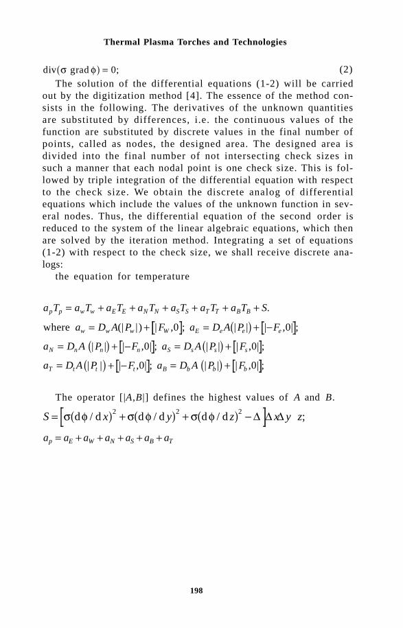
198
Thermal Plasma Torches and Technologies
div grad ;s f = 0 (2)
The solution of the differential equations (1-2) will be carriedout by the digitization method [4]. The essence of the method con-sists in the following. The derivatives of the unknown quantitiesare substituted by differences, i.e. the continuous values of thefunction are substituted by discrete values in the final number ofpoints, called as nodes, the designed area. The designed area isdivided into the final number of not intersecting check sizes insuch a manner that each nodal point is one check size. This is fol-lowed by triple integration of the differential equation with respectto the check size. We obtain the discrete analog of differentialequations which include the values of the unknown function in sev-eral nodes. Thus, the differential equation of the second order isreduced to the system of the linear algebraic equations, which thenare solved by the iteration method. Integrating a set of equations(1-2) with respect to the check size, we shall receive discrete ana-logs:
the equation for temperature
a T a T a T a T a T a T a T S.
a D A P F a D A P F
a D A P F a D A P F
a D A P | F a D A P F
p p w w E E N N S S T T B B
w w w W E e e e
N n n n S s s s
T t t t B b b b
= + + + + + +
= + = + -
= + - = +
= + - = +
where (| | ) | ,0 ; | | | ,0| ;
| | | ,0| ; | | | ,0| ;
| | ,0| ; | | | ,0| ;
The operator [|A,B |] defines the highest values of A and B.
S x y z x y z= + + -s f s f s fd / d d / d d / d ; 2 2 2 Y D D D
a a a a a a ap E W N S B T= + + + + +
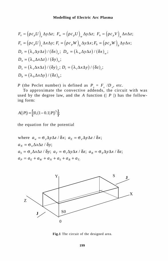
199
Modelling of Electric Arc Plasma
F c U y z F c U y z F c V x z
F c U x y F c W y x F c W y x
D y z x D y z x
D x z y
D x z y D x y z
D
e p e w p w n p
s p s t p b b p b
e e e w w w
n n n
s s s t t t
= = =
= = =
= =
=
= =
r r r
r r r
l d l d
l d
l d l d
D D D D D D
D D D D D D
D D D D
D D
D D D D
; ; ;
; ; ;
/ ; / ;
/ ;
/ ; / ;
n
b b bx y z= l dD D / ;
P (the Peclet number) is defined as Pe = F
e /D
e, etc.
To approximate the convective addends, the circuit with wasused by the degree law, and the A function (| P |) has the follow-ing form:
A P P| | |0, 1 0.1| | | ;5 = -
the equation for the potential
where / ; / ;
/ ;
/ ; / ; / ;
a y z x a y z x
a x z y
a x z y a y x z a y x z
a a a a a a a
w s E e
N n
S s T t B b
P E W N S B T;
= === = == + + + + +
s d s ds ds d s d s d
D D D DD DD D D D D D
Fig.1 The circuit of the designed area.
S J
X
Y
0
S0
Z
J
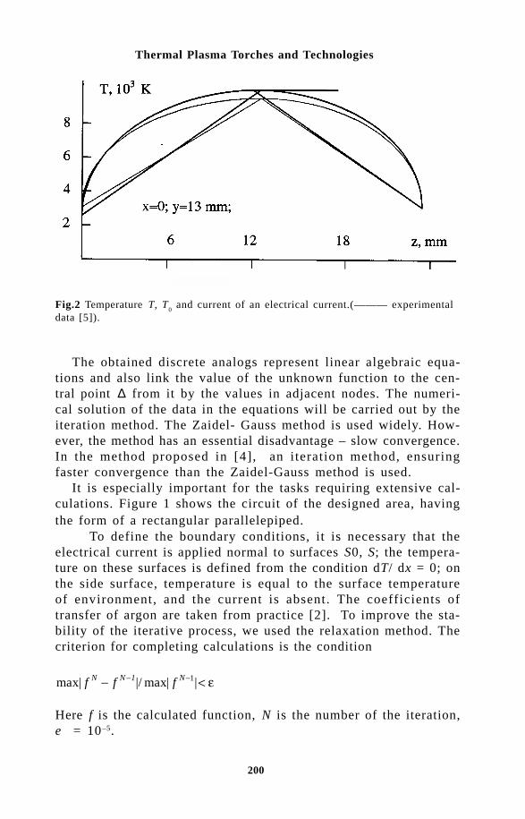
200
Thermal Plasma Torches and Technologies
The obtained discrete analogs represent linear algebraic equa-tions and also link the value of the unknown function to the cen-tral point ∆ from it by the values in adjacent nodes. The numeri-cal solution of the data in the equations will be carried out by theiteration method. The Zaidel- Gauss method is used widely. How-ever, the method has an essential disadvantage – slow convergence.In the method proposed in [4], an iteration method, ensuringfaster convergence than the Zaidel-Gauss method is used.
It is especially important for the tasks requiring extensive cal-culations. Figure 1 shows the circuit of the designed area, havingthe form of a rectangular parallelepiped.
To define the boundary conditions, it is necessary that theelectrical current is applied normal to surfaces S0, S; the tempera-ture on these surfaces is defined from the condition dT/ dx = 0; onthe side surface, temperature is equal to the surface temperatureof environment, and the current is absent. The coefficients oftransfer of argon are taken from practice [2]. To improve the sta-bility of the iterative process, we used the relaxation method. Thecriterion for completing calculations is the condition
max| |/ max| |1f f fN N 1 N- <- - e
Here f is the calculated function, N is the number of the iteration,e = 10–5.
Fig.2 Temperature T, T0 and current of an electrical current.(——— experimental
data [5]).

201
Modelling of Electric Arc Plasma
Figure 2 shows the calculations of of temperature T carried outfor argon plasma at the atmospheric pressure, current 75 A in asquare channel, sizes X = 30 mm; Y = 26.5 mm; Z = 26.5 mm. Thecomponents of speed Uy and Uz we equal to zero.
As the used method of solution follows from the outcome ofsolving differential equations, it ensures a steady, converging itera-tive process. The results of calculations are in satisfactory agree-ment with the experimental data [5].
One of most important problems of electric arc welding in ad-vanced engineering and metallurgy is the optimization of weldingconditions. It is necessary to carry out comprehensive research ofthermodynamic processes, running in welding pool, for producinghigh-quality welds. The fluid flow of molten metal in the weld poolin arc welds exerts a significant effect on the quality of the weldseam and the depth of weld penetration in the workpiece. For thispurpose, numerical and analytical models of heat transfer and liq-uid metal flow in welds in arc welding are required. This problemswas studied by Rozenthal [6] in an analytical model and numericalmodels were developed in [7-11]. In this work, we propose a nu-merical model of the weld pool, based on the simultaneous solutionof a complete system of magneto-hydrodynamic equations. It isassumed that the plane is the surface of the welded product. Theradius of the weld pool is 2–4 mm under normal welding condi-tions. It is also assumed that the welding arc is stationary and inweld pool metal is melted and incompressible, processes are sta-tionary, the liquid metal flow is laminar, crystallization processesare not considered. The heat flow flowing from the arc to theproduct and released in it due to Joule heating is distributed byconductive and convective flows. The metal motion is caused byelectromagnetic and buoyancy forces, pressure and surface tensiongradients, viscous stress. The boundaries of the weld pool (liquid-solid metal) are determined from the solution of the equations.
Fig.3 Schematic sketch of the weld pool.

202
Thermal Plasma Torches and Technologies
The model is based on a complete system of magneto-hydrody-namic equations
rot / grad * grad
/ / div div div( )
grad div / grad
V V V j B
V P V V
V h jE C hp
r r
r h ht r
r l
- = -
+ + + =
= - +
2
2 2 2 3 2 0
Y (3)
rotE = 0; j = rotH; divB = 0; divD = 0
The system is closed by the state equation and Ohm’s law:
D=ee0 E; B=m
0 H; j=sE
Here ρ, λ, η, σ, Cp are the thermodynamic functions and metal
transfer coefficients: density, heat capacity, viscosity, thermal andelectrical conductivity, respectively. The solution of the system (3)is carried out in the cylindrical coordinate system in view of sym-metry, and the boundary conditions are specified on the entire pe-rimeter of the computation range. For the energy equation, we havethe heat flow distribution on the pool surface or temperature dis-tribution. The temperature gradient on the open surface of thewelding pool ∂T/∂z is determined by the heat flow from the elec-tric arc to the welded product and heat losses into the ambient me-dium. The heat losses through the open surface are negligible be-cause of high melting point and high thermal conductivity of thewelded material. For the motion equation, the conditions are speci-fied: the axial velocity component u is equal to zero. Shear stress
Fig.4 Streamline and temperature fields m∂ ∂V z jB/ ,= =0 0 .

203
Modelling of Electric Arc Plasma
Fig.5 Streamline and temperature fields m∂ ∂ ∂v z T r t jB/ / * / ,= - = 0 .
Fig.6 Streamline and temperature fields.
µ(∂v/∂z) arises as the surface tension gradient γ on the weldingpool surface due to the significant radial temperature gradient asγ depends on temperature. For Maxwell’s equation, we define thecurrent density distribution on the surface. The conditions of ad-hering to the velocity are specified on the side and lower surfacesof the welding pool, temperature is supposed to be equal to thesolid metal temperature. The symmetry condition is satisfied on theaxis. Thus, the boundary conditions are written as follows (α -the heat boundary radius, b - boundary of metal solid phase):

204
Thermal Plasma Torches and Technologies
z r T z Q r
r R T T j j r
z r R u v z r
R z z
= £ £ =£ £ = == £ £ = = -
0 0
0 0 0
, : / ( )
: , ( )
, : , / /
a l∂ ∂a
m∂ ∂ ∂g ∂ (4)
0 0 0 0 0 0
0 0 0
0 0 0 0
2
£ £ = = = = =
£ £ = = = = =
= £ £ = = = =
z b r T u r v j r j
z b r R T T u v j I R
z b r R T T u v j z
z z
R
R z
, : / / , , / ,
, : , , , /
, : , , , /
∂ ∂ ∂ ∂ ∂
p
∂ ∂
This gives the closed mathematical model, determining heat andhydrodynamic flows in the welding pool. The numerical solution ofequation (3) with the boundary conditions (4) is made in variables‘vorticity (ω)–stream function’ (Ψ), enthalpy (h) and electric cur-rent function (χ) by the Zeidel–Gauss finite difference method ofaccording to a five-point scheme. Sheet aluminum was welded witha stationary electric arc, I =150 A. The radius and length of thewelding pool do not exceed 4 mm and 6 mm, respectively. Ther-modynamic functions, transport coefficients and the aluminium sur-face tension coefficient were taken from [12]. It is seen fromFig.4, where streamline fields (Ψ) are presented, that under theaction of the buoyancy force the melt metal rises up to the surfacefrom the central heated zone of the welding pool and colder liquidmetal sinks at the welding pool boundary. On the surface of theweld workpiece, the melt flow is directed from the axis radiallyoutwards and the maximum velocity reaches ~ 20 cm/s. This ischaracteristic for the flow regime; due to surface tension, the coldmetal draws off hot metal from the center, the maximum flow ve-locity reaches ~ 1m/s at the welding pool boundary. As is seenfrom Fig.5-6, liquid metal streamlines (ψ) change direction as aresult of the electromagnetic force action, the flow velocity on thewelding pool surface is directed to the axis of symmetry, the maxi-mum value reaches 20 cm/s, 50cm/s at the axis of symmetry. In theprocess of arc welding, all this three forces act simultaneously anda complicated (Fig.6) pattern of flow is realized: two vortices formin opposite directions. One of them is induced by the surface force,the other one by electromagnetic ones. The averaged velocity atthe surface is higher (6 cm/s) than the velocity in the vortex, in-duced by the electromagnetic force (50 cm/s). The temperaturefields show that the action of the electromagnetic force increasesweld metal penetration. The results are in satisfactory agreementwith the calculations [9–11]. With decrease of welding current (100
205
Modelling of Electric Arc Plasma
A) the maximum temperature, metal flow velocity and weld pen-etration decrease.
References1 M.F. Zhukov,Theory of thermal electric arc plasma. Science WITH,
Novosibirsk (1987).2 A. Zhainakov, et al, Electrical arc - generator of thermal plasma, Bishkek,
Ilim (1991).3 A. Zhainakov and T. Urusova, Numerical solution of a three-dimensional
heat conduction equation, Bulletin KGNU, Bishkek (1996).4 S.V. Patankar, Numerical methods of problem solving of heat exchange
and dynamics of a liquid, Energoatomizdat, Moscow (1984).5 M.K. Asanaliev, et al, Measurement of coefficient airdynamic resist-
ance of a sphere in argon to plasma.6 D. Rozental, Weld J.Res. Suppl. 20, 220 (1941).7 J.A. Shercliff, J. Fluid Mech., 40, 241 (1970).8 C. Sozou and W. Pickering, J.Fluid. Mech., 73, 641 (1970).9 D.R. Atthey, J. Fluid. Mech., 98, 787 (1980).1 0 S. Kou, Model Cast. And Weld Process, Proc. Sypm., Rindge (1982),
p.129.11 S. Kou and D. Sun, J.Metallur. Transact. A.,16A, 203 (1985).1 2 J.F. Lancaster, The Physics of welding, (1984), p.297.
206
Thermal Plasma Torches and Technologies
O.I. Yas’koHeat & Mass Transfer Institute, Academy of Sciences of Republic Belarus, 15 P.Brovky St. 220072 Minsk, Belarus
Turbulence is a very intricate phenomenon. More than hundred yearshave passed since Osborn Reynolds discovered his famous number, butscientists have not managed yet to propose a method for pure theoreticalsimulation of turbulent flows. A number of semiempirical methods aredeveloped for this purpose [1] that allow simulation of ‘cold’ turbulentflows, but high-temperature ones are much more difficult to model.Especially difficult for the conventional methods is the simulation ofelectric arc turbulence because of the nature of the processes dependson the discharge conditions. Using empirical constants obtained in anothersituation can lead to misleading results. Therefore, the simulation ofturbulent arcs is in urgent need of pure theoretical methods.
The basic hypothesis was proposed in [2] and verified in [3,4]. Theresults of this verification are considered in this paper.
The hypothesis assumes the existence of pairs of charges, with theproduct of their dimensions being equal to the Planck constant dimension.There are four of them: electric and magnetic charges, impulse – space,energy – time, mass – moment of velocity. They are considered as realcharges possessing mutual interactions. The assumption that mass is acharge such as electric one finds a confirmation in existing static gravitationalinteraction whose law is similar to that of electrical charges. The universalrelationship is obtained in [2] for calculating the constants for differ-ent charges static interaction. The theoretical value of the gravitationalconstant has turned to be in perfect agreement with experimental magnitude.But a moving electric charge creates a magnetic field. So the next assumptionmay be made that a special field is produced by any charge during itsmotion and that the Lorentz force is created due to interaction of the
207
On the Problem of Turbulent Arc Modelling
charge with the corresponding field. This suggestion complies with existenceof well known different vortices (tornadoes, cyclones in atmosphere,turbulence etc.) since the Lorentz force bends the trajectory of a movingcharge producing a swirl. It is shown below that these assumptionsopen the way for theoretical simulation of turbulent arcs.
! !"The above hypothesis entails the assumption that the known laws ofthe magnetic field may be applied to other ones created by moving differentcharges. But knowing such a basic constant like the field permeabilityis necessary for application of the laws. It can be attempted to find thisquantity from ‘Nature Triangle’ and the simple model of the electronstructure likewise it was done in [2] for estimating constants of staticinteractions.
For dynamic interaction, it is possible to suggest that the electronconsists of electrically charged ‘subparticles’ rotating around the centre.When the subparticles have different polarity of the charge q
i its value
can be equal to the total one. The magnitude of subparticle mass canbe also assumed to be equal to the total electron mass m
e. Though such
assumption involves negative mass, it complies with our main hypothesis– every charge can be positive or negative. The velocity of subparticlerotation must be close to that of light c, so that this utmost value maybe taken for evaluation.
For the magnetic field, the above assumptions give perfect agreementwith experiment when the average length of field line L corresponds tothe characteristic size of the electron D h m ce e= / 2π (h is Planck’s constant)divided by 2ϕ
e The last quantity can be derived from the ‘Nature Tri-
angle’ [2]. For the magnetic field, its theoretical value is equal toϕ
e = 137.10953≈137. This ϕ
e value leads to perfect agreement with ex-
periment for the theoretical constant of static interaction for electriccharges. For other fields, ϕ
i can be also estimated from the Triangle.
For a ‘vortex’ field, ϕv = 7.0585628×10⁹. So we may define for the general
case
Lh
m ci
e i
=4π ϕ (1)
It is seen from Eq. (1) that Lv for the electron is very short in comparison
with Lmagn
.The assumptions enable us to calculate separately the field induc-
tion in the electron Bi and its strength H
i. Their ratio gives the value

208
Thermal Plasma Torches and Technologies
of the permeability constant of a field moi
= Bi /H
i. Expressions for the
field flux and induction follow from the hypothesis
Φi ih q= (2)
BD
m c
hqi
i
e
e
i
= =4 16
2
2 2Φπ
π (3)
Field strength Hi is determined as H
i =I
i /L
i. Current I
i can be found
from the circular rotation of the subparticle in the electron
Iq c
D
q c m
hi
i
e
i e= =π
2 2
(4)
The field strength is determined by the expression
Hq m c
hi
i e i=8 2 3
2
π ϕ (5)
The formula for permeability can be written as follows
µϕi
i i
h
cq0 2
2= (6)
For the vortex field (qv
= me), m
m = 7.5474×10⁸ m/kg
The energy of a field has the following form
WB H H
ii i i i= =2 2
2µ (7)
A charged particle moving in the corresponding field with veloc-ity v
i is affected by the Lorentz force
F v Bi i= ¥qi (8)
Due to the trajectory bending by the Lorentz force, charged parti-cles begin to rotate. The expressions for the cyclotron radius and frequency
209
On the Problem of Turbulent Arc Modelling
take the form
r mv q Bi i i= ⊥ / (9)
f q B fi i i m= / 2π (10)
For the field induced by rotatable mass (qv
=m), the induction cor-responds to cyclotron frequency
B fm m= 2π (11)
At the low field energy, this kind of rotation can be considered asa ‘latent’ (or ‘implicit’) vortex which can change for ‘explicit’ one atthe critical conditions. The appropriate assumption about such conditionsis the excess of the field energy over the translation one for particlerandom movement W
f > W
tr=ρ v
tr2/2 (ρ is density). Hence, the criti-
cal condition can be defined as
ρ µv Htr i icr2
02
2 2= (12)
H vi cr tri
. =ρ
µ 0 (13)
For ideal gas (P /ρ = kT / m, vkT
mtr =8
π; P is pressure, T temperature,
k is the Boltzmann constant), Eq. (13) can be transformed to
HP
i cri
. =8
0πµ (14)
For the vortex field (mm.0
= 7.5474×10⁸ m/kg) at atmospheric pressure,H
cr = 1.837×10⁻²
0.02 kg/ms.Equation (14) shows that for a given ideal gas the critical value of
field strength depends only on pressure, and the possibility of explicit(‘free’) vortex arising increases with the pressure fall. Equation (14)is useful for estimating the critical conditions at local points.
Relations for the mass flow in a cylindrical canal (pipe) will be con-sidered below. In accordance with similarity of different fields, mass-flow density ρu (where u is the velocity of the flow) corresponds to
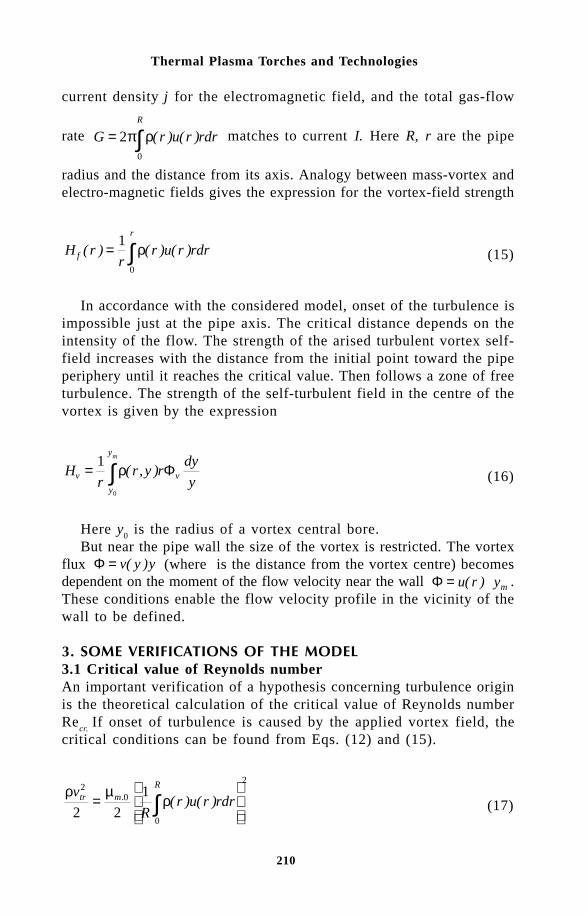
210
Thermal Plasma Torches and Technologies
current density j for the electromagnetic field, and the total gas-flow
rate G r u r rdrR
= ∫20
π ρ( ) ( ) matches to current I. Here R, r are the pipe
radius and the distance from its axis. Analogy between mass-vortex andelectro-magnetic fields gives the expression for the vortex-field strength
H rr
r u r rdrf
r
( ) ( ) ( )= ∫1
0
ρ (15)
In accordance with the considered model, onset of the turbulence isimpossible just at the pipe axis. The critical distance depends on theintensity of the flow. The strength of the arised turbulent vortex self-field increases with the distance from the initial point toward the pipeperiphery until it reaches the critical value. Then follows a zone of freeturbulence. The strength of the self-turbulent field in the centre of thevortex is given by the expression
Hr
r y rdy
yv v
y
ym
= ∫1
0
ρ( , ) Φ (16)
Here y0 is the radius of a vortex central bore.
But near the pipe wall the size of the vortex is restricted. The vortexflux Φ = v y y( ) (where is the distance from the vortex centre) becomesdependent on the moment of the flow velocity near the wall Φ = ⋅u r ym( ) .These conditions enable the flow velocity profile in the vicinity of thewall to be defined.
#" $ %"%& !3.1 Critical value of Reynolds numberAn important verification of a hypothesis concerning turbulence originis the theoretical calculation of the critical value of Reynolds numberRe
cr. If onset of turbulence is caused by the applied vortex field, the
critical conditions can be found from Eqs. (12) and (15).
ρ µρ
v
Rr u r rdrtr m
R20
0
2
2 2
1=
∫. ( ) ( ) (17)

211
On the Problem of Turbulent Arc Modelling
For the average ρ and U values
2
0
vRUtr
mµ ρ.
= (18)
Substituting vtr
=2ν / l, where n and l are the kinematic viscosity andmean free path [4,5], one can obtain
Re.
cr
m
UD
l= =
ν µ ρ8
0 (19)
The quantity (µm.0
ρ)0.5 is the characteristic length of the latent tur-bulent field. The critical value of the Reynolds number depends on theratio of this quantity to mean free path of the medium.
Now we can compare the theoretical value of with its experimentalmagnitude taking as an example the gas flow in a cylindrical pipe atatmospheric pressure and t = 0 °C. The values of l and ρ are takenfrom[5,6]. For nitrogen, we obtain ( ) ..
,µ ρm m00 5 53 26 10− −= × , l = 5.88
×10–8 m and Recr = 4430 . The theoretical value of the critical Reynoldsnumber is twice as high as the experimental one. The results obtainedare close to the experimental value, but the difference by a factor of2 can mean that the µ
m value is incorrect or onset of turbulence is caused
by a phenomenon other than the flow field. Moreover, the assumptionu(r) = const is crude. In a cylindrical pipe, the profile of the laminarflow which is converted into a turbulent one has the parabolic form:u r r( ) = −1 2 ,where u r u r U r r R( ) ( ) / , /= = u Uav = 0 5. . (R is the ra-dius of the pipe and U is axial velocity). The relative value of the localReynolds number for this condition can be described as follows
Re ( )locloc
rH
UR rr rdr r r= = − = −∫ρ
11
1
2
1
42
0
3 (20)
Maximum of Reloc
takes place at vrm = (2/3)0.5, and Re
loc m = 0.272 ≈
1/4. Since for the parabolic profile UR = uav
D, the critical Reynoldsnumber is approximatelly four times as high as its maximum local valueat the moment of turbulence origination. Therefore, the theoretical magnitudeof Re
cr is 8 times higher than Re
loc.
Of course, the model of the electron internal structure used for µm

212
Thermal Plasma Torches and Technologies
estimation is rather uncertain yet, and successful application of µm.0
forturbulence modelling would be very useful for its clarification. Therefore,another cause of the disagreement is likely to be examined.
For flow inside tubes, swirls are originated not only by the free vortexfield, but also by friction in the zone adjoining the tube wall. The wallfriction exists even in the laminar flow. Hence, only the friction nearthe wall is responsible for primary turbulence. This problem can be examinedconsidering Eq. (16). It may be adopted for the cold flow: ρ = const,and for given r and ideal vortex the flux Φ is also independent of r.Under these assumptions, Eq. (16) takes the form
H y yv m= -rF ln ln 0 (21)
Strength Hv
is induced by a vortex in its centre with the distanceapproximately y
m from the tube wall (neglecting the thickness of the
laminar sublayer). Quantity Hv
/ρ corresponds to the vortex forced bywall friction at this point: H
v/ρ =2y
mu
m= Φ (ln y
m– ln y
0). Factor 2 is
used because u corresponds to the centre of the vortex. This equationspecifies the velocity profile near the tube wall u
m(y
m) =H
v /2ρy
m=
(Φ /2ym) ln (y
m/y
0)= (Φ′/ 2 y
m) ln y
m – (Φ′/2y
m) ln y
0. It is known as the
experimentally obtained universal velocity profile for the turbulent flowwhen variables are presented in the dimensionless form: u+ = u/(τ
w /
ρ)0.5; y+ =ym
(τw
ρ)0.5/η; where η = ρν is dynamic viscosity and τw is
the shear stress at the wall [7]:
u y a b ym m+ + += +( ) ln (22)
Here a = –b ln y+0 and b =Φ
v /2n y+
m =u+
j. These factors are constant
because they correspond to the velocities at the wall for the flow andthe vortex, respectively u+
j: = b = const, u+
0 = a = const. The constant
value of a and b factors demonstrates that Φv has a linear dependence
on y+m
(Φv= 2bn y+
m) The function (22) is linear in semi-logarithmic
coordinates.The universal profile consists of a laminar boundary layer u+ = y+
and two linear parts (Fig.1).The strength of field H
v increases with y
m until it attains the criti-
cal value Hcr. The further rise H
v > H
cr causes the formation of free vortices
which create their own field directed oposite to the initial one. Thedevelopment of free eddies takes course until their field neutralises thewhole excess of H
v above H
cr. Therefore, at H
v > H
cr the strength of
the free vortex field is equal to Hfree
= Hv – H
cr. To make available this

213
On the Problem of Turbulent Arc Modelling
1 10 1000
5
10
15
20
u+
y+
u+=a1+b1lny+
u+=a2+b2lny+
u+=y+
Fig.1 Universal profile of velocity for wall turbulence
equality, the free vortex has to compensate a half of Hv. Hence
H pv l y y pv y y y
p v y pv y
cr v m v m cr free
m cr
= - - - =
= - +
+ + + + +
+ + +
F F
F F
ln ln . (ln ln ln )
. ln ln . ln
0 0
0
0 5
0 5 2 0 5
This expression corresponds to the second linear part of the universalvelocity profile u a b ym2 2 2
+ += + ln , where a a b ycr2 1 10 5= + +. ln and b2=0.5b
1.
The term ln y free0+ must be equal to zero since H
free= 0 at H
v=H
cr.
The field strength produced by the vortex Φv is a constant quantity
in the region H Hv cr> r because it is in equilibrium with the total field
H Htotal cr= . In such a case, the rise of field strength is attained only
at the expense of ln( / )y ym+ +
0 , and at the point H Hv cr= 2 , the termln y
m+ is two times higher than at Hcr . The point ln ln .y ym m cr
+ += 2 is theend of the universal velocity profile as the free vortex becomes self-sustaining at H Hfree cr> . This conclusion, as well as equality b
2 = 0.5b
1,
are in fair agreement with experiment. The contradiction between therising flux Φv mb y= +2 2ν and the constant value of its field strength canbe explained by the variability of the relative vortex permeability. In-duction of the field is constant over the considered zoneµ µ µ ρνm cr m m mH b y. .0 0 2= + . It follows from this that
µ ρνm cr mH b y= =/ 2 2 (23)
The form of the universal profile (Fig.1) can be derived theoretically.For this purpose, the boundary conditions have to be imposed in ad-dition to the general relations obtained above. The product of dimensionlessvelocity and distance is equal to the Reynolds number. Hence, for a bendingpoint it gives the critical value of this number
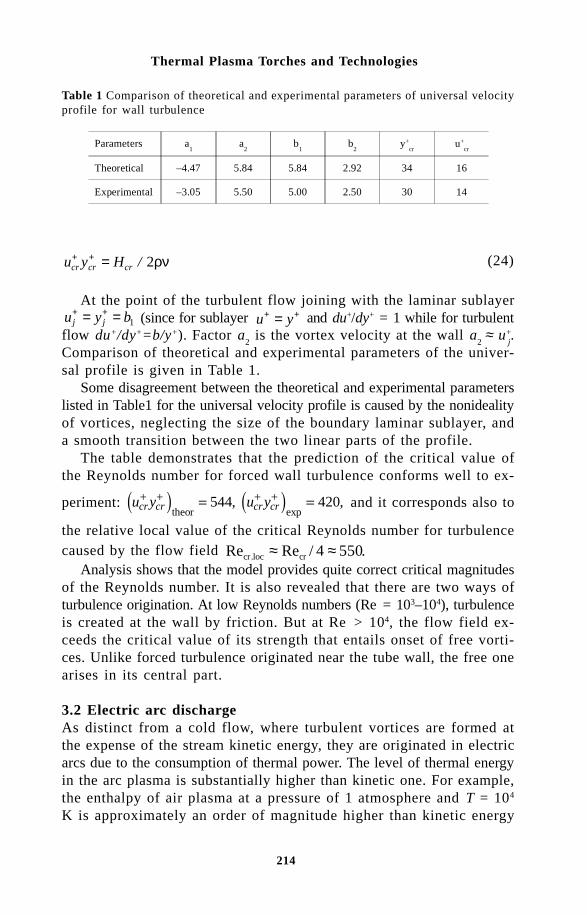
214
Thermal Plasma Torches and Technologies
u y Hcr cr cr+ + = / 2ρν (24)
At the point of the turbulent flow joining with the laminar sublayeru y bj j
+ += = 1 (since for sublayer u y+ += and du+/dy+ = 1 while for turbulentflow du+/dy+=b/y+). Factor a
2 is the vortex velocity at the wall a
2 ≈ u+
j.
Comparison of theoretical and experimental parameters of the univer-sal profile is given in Table 1.
Some disagreement between the theoretical and experimental parameterslisted in Table1 for the universal velocity profile is caused by the nonidealityof vortices, neglecting the size of the boundary laminar sublayer, anda smooth transition between the two linear parts of the profile.
The table demonstrates that the prediction of the critical value ofthe Reynolds number for forced wall turbulence conforms well to ex-
periment: u y u ycr cr cr cr+ + + += =
theor exp, ,544 420 and it corresponds also to
the relative local value of the critical Reynolds number for turbulencecaused by the flow field Re Re / .cr.loc cr≈ ≈4 550
Analysis shows that the model provides quite correct critical magnitudesof the Reynolds number. It is also revealed that there are two ways ofturbulence origination. At low Reynolds numbers (Re = 103–104), turbulenceis created at the wall by friction. But at Re > 104, the flow field ex-ceeds the critical value of its strength that entails onset of free vorti-ces. Unlike forced turbulence originated near the tube wall, the free onearises in its central part.
3.2 Electric arc dischargeAs distinct from a cold flow, where turbulent vortices are formed atthe expense of the stream kinetic energy, they are originated in electricarcs due to the consumption of thermal power. The level of thermal energyin the arc plasma is substantially higher than kinetic one. For example,the enthalpy of air plasma at a pressure of 1 atmosphere and T = 104
K is approximately an order of magnitude higher than kinetic energy
Table 1 Comparison of theoretical and experimental parameters of universal velocityprofile for wall turbulence
Parameters a1
a2
b1
b2
y+cr
u+cr
Theoretical –4.47 5.84 5.84 2.92 34 16
Experimental –3.05 5.50 5.00 2.50 30 14

215
On the Problem of Turbulent Arc Modelling
at the speed of sound (h = 4.78·107 J/kg; a2/2 = 3.56·106 J/kg). Usinghigher energy enables thermal turbulence to produce more intensivedisturbance of the flow.
Modelling turbulence in the electric arc is a much more complicatedproblem than in the cold flow. The processes of energy conversion andtransfer can predominantly affect the disturbance. Momentum and heattransfer processes caused by turbulence depend on vortex dynamics: onvortex formation, growth, and destruction. Vortex formation is controlledby the field critical conditions and development is promoted by the thermalnozzle effect which converts the thermal energy of arc plasma into kineticone of the vortices [6]. The growth of eddies is accompanied by heatingdue to energy dissipation caused by friction. Effect of the last proc-ess is rather appreciable even in comparison with Joule dissipation, especiallyin the vicinity of the vortex central bore. Due to the heatreleased byfriction, temperature and pressure rise inside the vortex but thermal nozzleacts in the opposite direction. This process can continue until the Lorentzforces become incapable of preventing destruction of the vortex by therising pressure. Then it is destroyed by explosion. The maximal velocityof exploded particles is defined by expression v h≈ 2∆ , where ∆h isthe enthalpy of vortex overheating.
The explosion of vortices can bring the main contribution into turbulentheat transfer in nonuniform temperature fields. However, turbulent vorticesaccumulate not only kinetic but also field energy. The latter also contributesto heat transfer. In such a case, we may try to apply an effective enthalpyincrement ∆h
ef. If this increment could be determined as a function of
temperature and mass flow fields, we would be able to simulate theo-retically turbulent discharges using an iteration procedure. The directbut still rather uncertain way is the modelling of vortex dynamics. Anotherpossibility is accounting for some general relationships peculiar to theeddies in the turbulent flow. To find some of these laws, we may takeinto consideration that the arising vortices generate their own field directedagainst the applied one but they can suppress only such a part of thisfield which exceeds the critical value H
cr.
There are four different zones along the radius of a turbulent arccolumn. The first zone spreads from the arc axis to the point where thestrength of the applied field becomes equal to the critical value. Theturbulent eddies are originated at this point and their self-field reachesH
cr at H
appl = 2H
cr.The vortices become self-sustaining at this point which
is the border between the second and third zones. In these regions, theswirling velocity of turbulent eddies can attain a high magnitude ow-ing to power supply with the thermal nozzle effect but it is limited bythe sonic velocity. Unlike cold flows, the electric arc is an intensive source
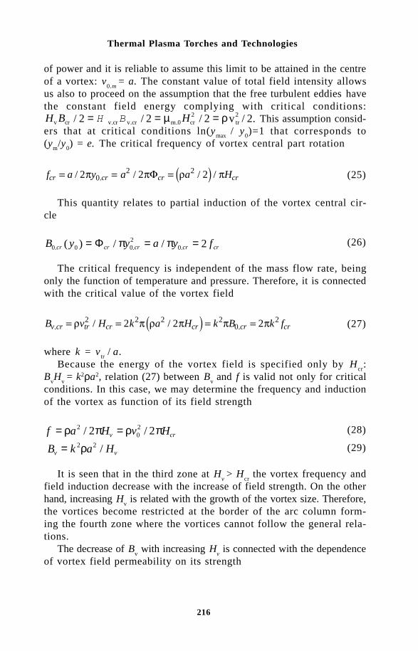
216
Thermal Plasma Torches and Technologies
of power and it is reliable to assume this limit to be attained in the centreof a vortex: v
0.m = a. The constant value of total field intensity allows
us also to proceed on the assumption that the free turbulent eddies havethe constant field energy complying with critical conditions:Hv cr v.cr v.cr m.0 cr
2tr2/ / / v / .B H2 2 2 2= = =H B µ ρ This assumption consid-
ers that at critical conditions ln(ymax
/ y0)=1 that corresponds to
(ym/y
0) = e. The critical frequency of vortex central part rotation
f a y a a Hcr cr cr cr= = =/ / / /.2 2 202 2p pF r p (25)
This quantity relates to partial induction of the vortex central cir-cle
B y y a y fcr cr cr cr cr0 0 02
0 2. . .( ) / /= = =Φ π π (26)
The critical frequency is independent of the mass flow rate, beingonly the function of temperature and pressure. Therefore, it is connectedwith the critical value of the vortex field
B v H k a H k B k fv cr tr cr cr cr cr. ./ /= = = =r p r p p p2 2 2 20
22 2 2 (27)
where k = vtr / a.
Because the energy of the vortex field is specified only by Hcr
:B
vH
v = k2ρa2, relation (27) between B
v and f is valid not only for critical
conditions. In this case, we may determine the frequency and inductionof the vortex as function of its field strength
f a H v Hv cr= =ρ π ρ π2022 2/ / (28)
B k a Hv v= 2 2ρ / (29)
It is seen that in the third zone at Hv > H
cr the vortex frequency and
field induction decrease with the increase of field strength. On the otherhand, increasing H
v is related with the growth of the vortex size. Therefore,
the vortices become restricted at the border of the arc column form-ing the fourth zone where the vortices cannot follow the general rela-tions.
The decrease of Bv with increasing H
v is connected with the dependence
of vortex field permeability on its strength
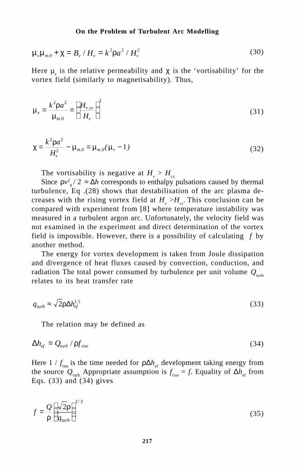
217
On the Problem of Turbulent Arc Modelling
µ µ χ ρv m v v vB H k a H. / /02 2 2+ = = (30)
Here µv is the relative permeability and χ is the ‘vortisability’ for the
vortex field (similarly to magnetisability). Thus,
µρ
µvm
v cr
v
k a H
H= =
2 2
0
2
.
. (31)
χρ
µ µ µ= − = −k a
Hvm m v
2 2
2 0 0 1. . ( ) (32)
The vortisability is negative at Hv > H
cr.
Since ρv20 / 2 ≈ ∆h corresponds to enthalpy pulsations caused by thermal
turbulence, Eq .(28) shows that destabilisation of the arc plasma de-creases with the rising vortex field at H
v >H
cr.
This conclusion can be
compared with experiment from [8] where temperature instability wasmeasured in a turbulent argon arc. Unfortunately, the velocity field wasnot examined in the experiment and direct determination of the vortexfield is impossible. However, there is a possibility of calculating f
by
another method.The energy for vortex development is taken from Joule dissipation
and divergence of heat fluxes caused by convection, conduction, andradiation The total power consumed by turbulence per unit volume Q
turb
relates to its heat transfer rate
q hturb ef≈ 2 1 5ρ∆ . (33)
The relation may be defined as
∆h Q fef turb rise= / ρ (34)
Here 1 / frise
is the time needed for ρ∆hef
development taking energy fromthe source Q
turb. Appropriate assumption is f
rise = f. Equality of ∆h
ef from
Eqs. (33) and (34) gives
fQ
qturb
=
ρ
ρ22 3/
(35)
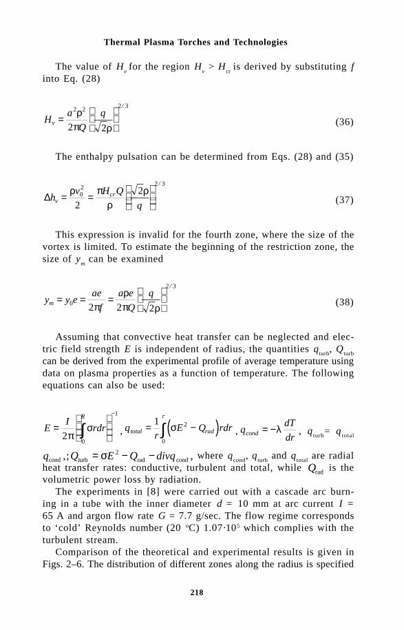
218
Thermal Plasma Torches and Technologies
The value of Hv for the region H
v > H
cr is derived by substituting f
into Eq. (28)
Ha
Q
qv =
2 2 2 3
2 2
ρπ ρ
/
(36)
The enthalpy pulsation can be determined from Eqs. (28) and (35)
∆hv H Q
qv
cr= =
ρ πρ
ρ02
2 3
2
2/
(37)
This expression is invalid for the fourth zone, where the size of thevortex is limited. To estimate the beginning of the restriction zone, thesize of y
m can be examined
y y eae
f
a e
Q
qm = = =
0
2 3
2 2 2πρπ ρ
/
(38)
Assuming that convective heat transfer can be neglected and elec-tric field strength E is independent of radius, the quantities q
turb, Q
turb
can be derived from the experimental profile of average temperature usingdata on plasma properties as a function of temperature. The followingequations can also be used:
EI
rdrR
=
∫
−
20
1
πσ , ( )q
rE Q rdrtotal rad
r
= −∫1 2
0
σ , qdT
drcond = −λ , qturb
= qtotal
q Q E Q divqcond turb rad cond,; ,= − −σ 2 where qcond
, qturb
and qtotal
are radialheat transfer rates: conductive, turbulent and total, while Qrad is thevolumetric power loss by radiation.
The experiments in [8] were carried out with a cascade arc burn-ing in a tube with the inner diameter d = 10 mm at arc current I =65 A and argon flow rate G = 7.7 g/sec. The flow regime correspondsto ‘cold’ Reynolds number (20 oC) 1.07·105 which complies with theturbulent stream.
Comparison of the theoretical and experimental results is given inFigs. 2–6. The distribution of different zones along the radius is specified

219
On the Problem of Turbulent Arc Modelling
0,0 0,5 1,0 1,5 2,0 2,5 3,00
2
4
6
8
10
r,mm
Hvx102
kg/ms
Fig.2 Profile of vortex field strength in argon arc, I = 65A, G = 7.7g/s, d = 10mm.
0,0 0,5 1,0 1,5 2,0 2,5 3,00
1
2
3
1 2 3
r, mm
qx10-6,W / m2
Fig.3 Heat transfer rates profiles: 1) qS; 2) q
cond; 3) q
turb.
by the profile of vortex field strength (Fig.2). It is seen that the freevortex is initiated at r ≈ 0.25 mm. In accordance with the model, theturbulent heat flux must also originate at this point, and it is confirmedby Fig.3. Critical value H
v = 1.837·10–2 kg/ms corresponds to r ≈ 0.9
mm which is the end of the second zone. Theory predicts that enthalpypulsation begins to decrease from this point. This prediction is also ingood agreement with experiment that is exhibited by Fig.4. The restrictionof the vortex size begins from r ≈ 2.25 mm. It causes the bending of

220
Thermal Plasma Torches and Technologies
0,0 0,5 1,0 1,5 2,0 2,5 3,00,2
0,4
0,6
0,8
1,0
1,2
1,4
1
2
3
r,mm
∆Hx10-6
m2/s2
Fig.4 Enthalpy pulsation in turbulent argon arc: 1 - experimental profile; 2 - theoreticalprofile (correction: y
m = const in the restriction zone); 3 - theoretical profile without
ym correction.
0,0 0,5 1,0 1,5 2,0 2,5 3,00
5
10
15
20
25
r,mm
ymx104,mm
Fig.5 Vortex size profile for a turbulent argon arc.
the Hv curve at this point (Fig.2). The same effect is seen in Fig.5 that
demonstrates the plot of ym profile. Thus, a number of effects give evidence
in the favour of the hypothesis verified.An additional evidence in the favour of our model follows from Fig.3

221
On the Problem of Turbulent Arc Modelling
exhibiting the plots of heat transfer rates in the considered arc. It isseen that at r ≈ 0.9 mm q
turb ≈ q
cond. In accordance with Fig.2, this point
corresponds approximately to Hv = H
cr, where vortices become self-sustaining.
Turbulent heat transfer is less than conductive one at r < 0.9 mm, butit becomes dominant at r > 0.9 mm inspite of ∆h
falling rapidly in this
region (see Fig.4). Since ∆h relates to the maximal velocity of turbu-lent vortex rotation, this result shows that the pulsation of kinetic energyis unable of explaining the domination of turbulent heat transfer in thisregion and only consideration of the field energy contained in destructionof the vortices together with the kinetic describes the situation.
Another important confirmation of the verified model is also providedby Fig.6, which compares the effective enthalpy increment obtained fromthe average temperature profile 3/2
exp.)1( )2/( ρturbef qH =∆ and that basedon experimental temperature instability accounting for theoretical re-lations exp
2)2( / HHQH crturbef Λ=∆ ρπ . It is seen that agreement is rather
good with the exception of the restriction zone, and this plot also showsr = 2.25mm as the border between the third and fourth zones.
'"""(! " !!The direct way for turbulent arcs modelling is connected with theconsideration of nonstationary vortex behaviour in nonuniform temperatureand velocity fields. But such a method is a very tedious one. It is expedientto simplify the procedure by bringing in some basic relationships. Theexpressions obtained above can be useful for this purpose. As it is shownabove, the key factor in turbulent arcs modelling is the effective enthalpy∆H
ef. It can be obtained from Eqs.(33)–(35)
( )12 1 5
r
d
drr H f Hef efρ ρΛ Λ. = (39)
0.0 0.5 1.0 1.5 2.0 r,mm3.0
0
20
40
80
60
- 1
- 2
∆hef,
kJ/kg
Fig.6 Radial distribution of effective enthalpy increment: 1) ∆hef1; 2) ∆h
ef2.

222
Thermal Plasma Torches and Technologies
If initial temperature and velocity profiles are known, f can be foundfrom Eq. (35) that enables ∆H
ef to be derived from Eq. (39). Coeffi-
cients of turbulent thermal conductivity and kinetic viscosity can be obtainedfrom the following expressions
λ ρΛTURB efHdT
dr=
2 1 5. / (40)
ν turb efHdu
dr=
2Λ / (41)
The profiles obtained assuming the laminar flow can be applied asinitial and they can then be numerically recalculated using turbulentcoefficients together with the molecular ones. Such an iteration procedurewill apparently provide the correct result. Some difficulties can arisein the fourth zone of vortex size restriction, where disagreement betweenthe two forms of effective enthalpy is revealed (Fig.6), but this prob-lem can be solved by applying appropriate corrections.
It is of interest that Hv exhibits a linear dependence on radius (Fig.2).
In accordance with Eq. (15), this relation conforms to the uniform distributionof the mass flow-rate across the arc column ru = const. For the con-sidered experiment ρu = 67.5 kg/m2 s or ≈70% of the average value.If it is not a specific case but a general law representing, for exam-ple, minimizing free energy, then this relationship will greatly facili-tate turbulent arcs modeling.
Theoretical simulation of turbulent arcs would be also useful for modellingcold flows.
)!""A hypothesis of the existence a special vortex field created at mass movementis verified. It has turned out to be quite useful, enabling us to derivetheoretically the critical value of the Reynolds number and the universalvelocity profile for the cold turbulent flow. Comparison of the theoreticalpredictions with the experimental data for electric arc discharge alsodemonstrates good agreement. It is shown that the instability of arc dischargesis governed by the vortex field laws. Heat and momentum transfer arespecified by turbulent eddies in uneven temperature and velocity fields.The speed of vortex rotation increases up to sonic one at the expenseof thermal energy due to the thermal nozzle effect. The theory revealsthat four specific zones of turbulence can arrive in an electric arc. Generalrelationships for estimating parameters of turbulence are derived. Using

223
On the Problem of Turbulent Arc Modelling
this approach, it may be possible to develop methods for pure theoreticalsimulation of turbulent flows including plasma flows in electric arcdischarges.
ACKNOWLEDGMENTSGrateful acknowledgments are made to the Fund of Fundamental Research of Belarusfor support of the study on thermal turbulence and to INTAS-94-2922 for supportof the research on electric arcs modelling.
NOMENCLATUREa - sonic velocity; B - induction of field; c - light velocity; D - diameter;D
e - characteristic size of electron; E - electric field strength; e - basis of
natural logarithm; F - force; f - frequency; G - gas flow rate; H - strengthof field; h - enthalpy, Plank constant; ∆h - enthalpy increment; I - current;j - current density; k - Boltzmann constant; L - average length of field line;l - mean free pass; m - mass; - P - pressure; Q - power per unit volume;q - charge, heat transfer rate; R - radius of canal; r - radius; T - temperature;u - velocity of flow; v - velocity of vortex; W - field energy per unit volume;y - radius of vortex; ∆ - increment; η - dynamic viscosity; λ - thermal conductivity;µ - field permeability; ν - kinematic viscosity; ρ - density; σ - electricalconductivity; τ - shear stress; Φ - field flux; ϕ - parameter of ‘Nature Triangle’;χ - vortisability of eddy.Subscripts: appl - applied av - average; cond - conductive; cr - critical; e- electron; exp - experimental; i - varying; j - joining; lim - limited; loc -local; m - mass, maximal; o - vacuum, central; rad - radiate; rise - rising;theor - theoretical; tr - translation; v - vortex; w - wall.Superscripts: + - nondimensional.
References1 B.E. Launder and D.B.Spalding, Mathematical Models of Turbulence,
Academic Press, London and New York (1972).2 O.I. Yas’ko, An elementary model of microworld, (Preprint N0 19 / Luikov
Heat & Mass Transfer Institute , Russian), Minsk (1986), p.47.3 O.I. Yas’ko, On the character of turbulence in electric arc,(Preprint No2,
Heat and Mass Transfer Institute ) Minsk (1996), p.22.4 O.I. Yas’ko, A new approach to turbulent arcs modelling, (Preprint N0
2 / Heat & Mass Transfer Institute), Minsk (1997), p.24.5 G.W. Kaye and T.H.Laby, Tables of Physical and Chemical Constants,
Longmans, Green & Co, London, New York and Toronto (1958).6 S.S. Kutateladze and V.M.Borishansky, Reference Book for Heat Transfer,
(Russian), Gosenergoizdat, Leningrad and Moscow (1959).7 E.R.G. Eckert and R.M.Drake, Jr., Heat and Mass Transfer (1959).8 Y.K. Chien and D.M.Benenson, IEEE Trans. on Plasma Science, PS-
8, No.4, 411-417 (1980).

224
Thermal Plasma Torches and Technologies
A.N. Timoshevskii, B.A. Pozdnyakov and V.S. PonkratovInstitute of Theoretical and Applied Mechanics, SB RAS, Novosibirsk
Research into the use of low-temperature plasma in chemistry, metallurgy,machinery and some other industries is being carried out in differentcountries. Plasma processes cover heavy industries as well as industriesproducing small amounts of special substances and materials. The mostdeveloped installations for the generation of low-temperature plasmaare electric-arc plasma torches because of their reliability and stableoperation, a wide range of power used, and the ability to heat differentgases.
Plasma torches working on argon, hydrogen, air, methane and ni-trogen have been described extensively in the literature [1–3], but thereis almost no data on compositions with fluorine. For example, a plasmatorch with tetrafluoromethane (CF
4) as a working gas may be of con-
siderable interest for chemical industry. There is a small amount of datain the literature on the plasma torch characteristics. As an example,we can consider Ref. [4] describing a plasma torch with a self-aliningarc length; the plasma torch works on CF
4 (Fig. 1a).
A graphite bar worked as a cathode in the plasma torch; it was placedin a copper water-cooled holder (with the help of a threaded connection).The output electrode was made of copper; its length was 0.12 m, andthe anode diameter changed from 1 to 2×10⁻² m. The experimental dataobtained using an electric current power of 100–600 A were gener-alised to derive an equation for calculating the volt–ampere charac-teristic of this plasma torch:
U = 539 (Gdp/J) 0.29 [Volt],
where G is the gas flow rate [kg/s]; d the channel diameter [m],

225
Energy Characteristics of Electric Arc Heaters for Tetrafluoromethane
p the pressure [Pa], J the electric current power [A].The heat characteristic has the form:
η = 1.14 × 10⁻³ (I2/Gd)0.94 (G/d)–0.12 (l/d)0.62
As in Ref. [4], the pressure in the plasma torch channel was not variedin these experiments. The anode diameter was varied in a narrow range.
Consequently it is not possible to evaluate the effect of the Knudsennumber, expressed as (p. d), on either the volt–ampere characteristicof the arc or the specific heat losses in the plasma torch. Besides, plasmatorches with the self-alining arc length always have a drooping volt–
Fig.1

226
Thermal Plasma Torches and Technologies
ampere characteristic and, therefore, the real behaviour of the elec-tric field of the arc in CF
4 is not known. From the equation of the plasma
torch heat characteristic, we conclude that the specific heat losses risewith electric current as ~I0.2, when the relative length of the plasmatorch channel associated with the arc length is included in the equa-tion ~(l/d)0.62. Thus, the increase of the single plasma torch power seemsto be realized more effectively by increasing the arc length, i.e. by usingplasma torches with a fixed length (with a step in the output electrode)and plasma torches with interelectrode inserts.
Therefore, the following research problems were outlined:a ) to obtain data on the behaviour of an arc burning in CF4 in a wide
range of parameters. The parameters are: the diameter of plasma torchchannel, the arc column length, output pressure, the plasma-forminggas flow rate, electric current power, etc;
b) to determine the dependence of the electric field strength on thechannel diameter and electric current power;
c) to derive generalized equations of the electric and heat characteristicsof the plasma torch with a fixed arc length.
Several designs of plasma torches were studied (Fig.1). Figure 1bshows a plasmatorch with the average arc length fixed with a step;Fig. 1c shows a plasma torch with an interelectrode insert. In eachexperiment, a bar made from dense graphite was used as the cath-ode. It was pressed flush into a copper water-cooled holder. A cylindricalanode made from copper worked as the output electrode.
Experiments were carried out in the following ranges of the oper-ating parameters: electric current power of the arc was 100–1000 A,total flow rate of tetrafluoromethane in the plasma torch was (1.3–40)×10–3 kg/s, the geometrical dimensions of the diaphragm were constant:d
1 = 9 mm, l
1 = 10 mm, the length of the interelectrode insert was varied
from l2 = 400–720 mm, diameter d
2 = 4–35 mm. The anode dimen-
sions d3, l
3, d
4, l
4 were varied, but the ratios d
4/d
3 and l
4/l
3 were constant,
0.7 and 1.2, correspondingly. The pressure at the plasma torch exit inmost experiments was 105 Pa. A few control experiments were car-ried out at pressure of 104 Pa.
Typical volt–ampere characteristics of the plasma torch arc for differentdischarge channel are shown on Fig.2. Let us consider some of pre-viously unknown facts:
– very weak dependence of voltage on electric current;– small change of voltage with the plasma-forming gas (CF
4) flow
rate;– volt–ampere characteristics have falling and rising areas;– transition of the falling branch into an increasing one occurs when
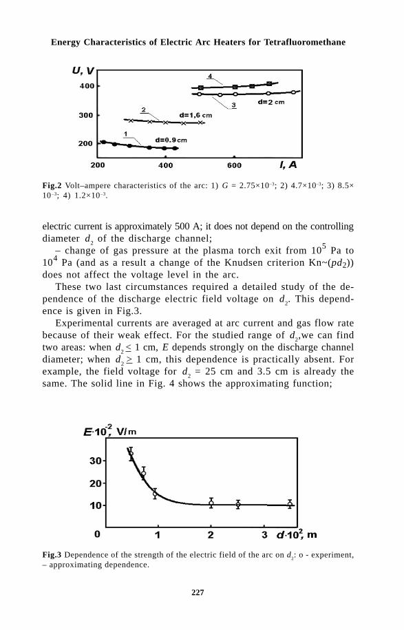
227
Energy Characteristics of Electric Arc Heaters for Tetrafluoromethane
electric current is approximately 500 A; it does not depend on the controllingdiameter d
2 of the discharge channel;
– change of gas pressure at the plasma torch exit from 105 Pa to104 Pa (and as a result a change of the Knudsen criterion Kn~(pd2))does not affect the voltage level in the arc.
These two last circumstances required a detailed study of the de-pendence of the discharge electric field voltage on d
2. This depend-
ence is given in Fig.3.Experimental currents are averaged at arc current and gas flow rate
because of their weak effect. For the studied range of d2,we can find
two areas: when d2 < 1 cm, E depends strongly on the discharge channel
diameter; when d2
> 1 cm, this dependence is practically absent. Forexample, the field voltage for d
2 = 25 cm and 3.5 cm is already the
same. The solid line in Fig. 4 shows the approximating function;
Fig.3 Dependence of the strength of the electric field of the arc on d2: o - experiment,– approximating dependence.
Fig.2 Volt–ampere characteristics of the arc: 1) G = 2.75×10⁻³; 2) 4.7×10⁻³; 3) 8.5×10⁻³; 4) 1.2×10⁻³.

228
Thermal Plasma Torches and Technologies
E = ψ (4.10–5/d2 + 1)V,
where ψ is a function of the energy criterion.Correlation between arc current and is shown in Fig.4 for all pa-
rameter ranges examined in these experiments.For engineering calculations in current ranges above 300 A, this depend-
ence may be taken as constant. Consequently, the approximating de-pendence on the energy criterion has a falling trend for simplifying thegeneralized volt–ampere characteristic equation. The equation has theform:
U = 3.5 × 10³ . (I2/Gd2)–0.05(4×10–5/d
22 +1) L
a, Volt,
where La is arc length.
The full arc length is calculated as
L = (l2 + +2.7d
2), m.
Component δ is a design dimension – from the cathode power tothe beginning of the interelectrode insert; the second component is thearc length in anode capacity. Anode geometry and the average regionof the anode spot root are similar and are accurately determined asdimension d
2.
The averaged equation is accurate in the following ranges of pa-rameters: I2/Gd
2 = (0.59–1.2) × 109, d
2 = (6–35) ×10–3 m, l
2 = (6–74)×
10–3, p = 104105 Pa.Heat losses into the plasma torch elements were estimated in the
experiments. The generalized equation of efficiency is also derived fromresults of measurements and has the form:
η = 1–η /η = 4.37×10⁻⁷(I2/Gd2)0.25(G/d)–0.94(pd)0.68L1.15
Fig. 4. Generalized experimental data on in ranges: d = (6–35) × 10–3 m, G = (1.3–40)× 10–3 kg/s.

229
Energy Characteristics of Electric Arc Heaters for Tetrafluoromethane
where L = Σ ln/d
n is the relative length of the discharge channel.
The accuracy of this formula is 15% in the following range of theparameters:
(I2/Gd2) = (1.1–4.8) ×105[A2 × s × kg–1 × m–1], G/d = (0.204–0.560)
[kg . s–1 . m–1], pd2 = (0.6–3.5) . 103 [Pa. m]
Agreement of the experimental data with the calculated results isshown in Fig. 5.
If in the equation of efficiency we change the relative length of thedischarge channel L to the full length of the arc colomn L
a and make
some transformations, we will have:
η = 4.37 . 10–7 (I/d2)0.5 (pd
2)0.68 (d
2/G)–0.05 (L
a/G)1.15
Hence it follows that– the relative heat losses are practically independent of the Reynolds
number which is determined by d2
– dimension complex G/d2;
– the relative heat losses depend strongly on the Reynolds numberwhich is determined by arc length ~ G/L
a; these heat losses exceed
considerably the influence of the complex I/d (transformed energy criterion);– the working gas pressure has a strong effect on the plasma torch
section through the Knudsen criterion – dimension complex pd2.
When designing plasma torches in practice, care should be takenwhen selecting methods of obtaining the required power with minimumenergy losses.
Fig.5 Comparison of the experimental and calculated efficiency.

230
Thermal Plasma Torches and Technologies
References1 M.F. Zhukov, et al, Applied dynamics of thermal plasma, (in Russian),
Novosibirsk, Nauka (1975).2 M.F. Zhukov, et al. Basis of calculation for plasma torches with the linear
scheme, (in Russian), Novosibirsk (1977).3 M.F. Zhukov (ed), Plasma torches. Research. Problems, (in Russian),
Novosibirsk (1995).4 V.S. Saidurov and G.N. Trunov, In: Electric-arc heater of tetrafluoromethane
with vortex arc stabilization (in Russian), Materials of VII Conferenceof low-temperature plasma generators, Vol.1, Alma-Ata (1977).

231
Numerical Investigation of the Characteristics of a Steady Curved Arc
G.A. Desyatkov, V.Ts. Gurovich and E.B. KulumbaevKyrgyz-Russian Slavonic University, Bishkek, Kyrgyzstan
!" External gas-dynamic and magnetic fields are widely used to controlthe geometry and characteristics of electric arcs in many plasma devices.The interaction of an arc with external fields leads to a change of thearc shape and generation of gas flows in plasma. As a result, an arccurved under external actions is characterised by the absence of axialsymmetry and is essentially a three-dimensional formation. In a generalcase, the problem of theoretical analysis of the properties of a curvedarc requires us to consider a set of the unsteady spatial equations ofmagnetic gas-dynamics [1]. A solution of such a problem is connectedwith significant difficulties, and up to the present time only theapproximate approaches based on various simplified theoreticalassumptions or requiring experimental data on local arc parameterswere developed.
Representations about the physical picture of an arc motion advancedin the papers [2,3] allow us to determine its shape as the location ofthe line of maximum temperature in space. On the basis of the simi-lar approach, the model of spatial-temporary dynamics of the arc shapein external gas-dynamic and magnetic fields of various geometry wasdeveloped [4,5]. The basic problem of construction of models for findingthe arc shape is the determination of the plasma flow velocity in theregion of maximum arc temperature. Two opposite cases are usuallyconsidered [6]: a gas flow around or gas flow through the near-axisarc zone. Therefore, the choice of a regime of gas flow for the modelrequires independent substantiation.

232
Thermal Plasma Torches and Technologies
The realised approaches to numerical determination of the characteristicsof a curved arc are reduced to the analysis of a steady straight arcin crossed magnetic and gas-dynamic fields [1]. In a number of cases,the experimental temperature fields are used for the determination ofthe gas-dynamic picture [7].
In this work, the self-consistent calculations of the characteristicsof a steady curved arc in its cross section were carried out and thesimple estimation of plasma velocity in the region of maximum arctemperature is offered.
# $%$ && 'In [4,5], a simplified model has been developed which allows us to investigatethe space–time evolution of low-current arcs in external gas-dynamicand magnetic fields of different geometry. The analysis has been basedon the consideration of arc motion as displacement of its temperaturefield due to the asymmetry of energy release and heat flux in the curvedarc. The energy equation describing the temperature distribution insidean optically thin arc has the form
( )1 1 2
χ∂∂ χ
σ ψS
tU S S E+ ⋅ ∇ = + −r r
∆ ,
where S is the heat flux potential determined by dS = λ(T) dT; T thetemperature; r
U the plasma velocity vector; E the electric field strength;
χ λ ρ= / cp is thermal diffusivity; ρ is mass density; λ is heat conductivity;
cp is the heat capacity; σ is electrical conductivity; ψ is the volume
radiation density; and t is time.Equation (1) is solved together with the Maxwell equation
rotr rE B t= −∂ ∂/ ,
which determines the distribution of the electric field strength insidethe arc, where
B is magnetic induction.This model allowed us to obtain the equations for arc dynamics in
the form
( ) ( )[ ]( )
r r
r rV u k E
V u
p a
p a
⋅ − = − + − −
⋅ − =
ν χ ψ σ
β
ν
β
0 0 0 0 021 4 1
0
/ ,
,

233
Numerical Investigation of the Characteristics of a Steady Curved Arc
which determines the dynamics of the instantaneous local curvaturek
0 of the axial line of the arc as the function of the plasma velocity
Vp in the region of the arc temperature maximum. Here u ua aν β, are
the velocities of arc element motion in the normal and binormal directions;χ λ ρ ψ σ0 0 0 0 0 0= / , ,cp are the plasma parameters at T=T
max.
However this approach does not allow to determine the tempera-ture and gas flow fields inside an arc.
( ) & *$) ! * +" We consider the problem of numerical modelling the curved arc underthe following formulation. Let in a result of action of a cross gas flow(or mass forces), the arc burning between two motionless electrodeshas got a steady-state curved shape (Fig.1,a). We shall determine thecharacteristics of plasma in the cross section of an arc located in aplane of its symmetry (see shaded area on Fig.1) near to which a non-uniformity of the characteristics in the direction perpendicular to it isneglected. Such problem is stationary, spatially two-dimensional and canbe considered in the Cartesian system of coordinates x, y where thex-axis is directed along the gas flow and the y-axis is perpendicularto it (Fig.1,b).
It is supposed that the gas flow is laminar, plasma is in the localthermodynamic equilibrium, radiation is volume, influence of the selfmagnetic field on the arc characteristics is negligible. Then the set ofthe Navier-Stokes equations can be written in the following form:
The equations of motion
ρ ∂∂
ρ ∂∂
ρ ∂∂
∂∂
η ∂∂
∂∂
η ∂∂
∂∂
∂∂
η ∂∂
∂∂
uu
xv
u
yF
p
x x
u
x y
u
y
v
x x
u
x
v
yx+ = − +
+ +
− +
2
2
3 (1a)
Fig.1 The picture of arc burning in a cross gas flow (a) and the scheme of computationalregion (b).
a
∞
b
∞
−

234
Thermal Plasma Torches and Technologies
ρ ∂∂
ρ ∂∂
ρ ∂∂
∂∂
η ∂∂
∂∂
∂∂
η ∂∂
∂∂
η ∂∂
∂∂
uv
xv
v
yF
p
y x
u
y
v
x y
v
y y
u
x
v
yy+ = − + +
+
− +
2
2
3
the equation of continuity
( ) ( )∂∂
ρ ∂∂
ρx
uy
v+ = 0 (1b)
the equation of energy balance
ρ ∂∂
ρ ∂∂
∂∂
λ ∂∂
∂∂
λ ∂∂
σ ψuCT
xvC
T
y x
T
x y
T
yEp p+ =
+
+ −2
(1c)
Here u, v are the velocity components on the axis x and y accordingly;p is pressure; E is the modulus of the electrical field strength vectorperpendicular to the plane (x, y); F Fx y, are the components of massforce density. The mass density ρ, dynamic viscosity η, thermal conductivityλ, electrical conductivity σ and volume radiation density ψ of the plasmaare the given functions of temperature. It is supposed that the changeof pressure inside the arc is insignificant in comparison with atmos-pheric one and its influence on the plasma transport properties is neglected[1].
The non-uniformity of the electrical field inside the arc along thex-axis caused by the curvature of its column is found from the solu-tion of the equation ∇ × =
rE 0 . Accounting the chosen direction of the
coordinate axes it is approximately written as [4,5]
( ) ( )E x E x Rk= +0 1 (2)
where E0 is the electric field strength on the line of the temperature
maximum having the curvature radius Rk at the point (0,0) (Fig.1). The
values of E0 and R
k are considered to be given.
The boundary conditions for the system of the elliptical equations(1) are set on the whole contour of the computational region whichdue to a symmetry of the problem accordingly the x-axis is limited bythe coordinates l x l y lx x y1 2
0≤ ≤ ≤ ≤, (see Fig.1,b). They have the form:– the conditions of the uniform cold flow on the entrance bound-
ary:
235
Numerical Investigation of the Characteristics of a Steady Curved Arc
x l y l u u v T Tx y= ≤ < = = =∞ ∞10 0, : , , ;
– the normal gas outflow conditions from the computational regionon the exit boundary:
x l y l u x v T x p px y= ≤ ≤ = = = = ∞20 0 0 02 2, : ( ) / , , / , ;∂ ρ ∂ ∂ ∂
– the conditions of symmetry on the arc axis:
l x l y u y v T y p yx x1 20 0 0 0 0≤ ≤ = = = = =, : / , , / , / ;∂ ∂ ∂ ∂ ∂ ∂
– on the side boundary - the conditions of sticking for the gas flowin the channel:
l x l y l u v T Tx x y1 20≤ ≤ = = = = ∞, : ,
or the conditions of the uniform cold gas flow in free space.For the arc in an external mass field, the boundary conditions of
normal gas penetration through the boundary at the given pressure areimposed on entrance, outflow and side boundaries.
The arc current is calculated from the formula
I Edxdyl
l
l y
x
x
= ∫∫20
1
2
σ (3)
, '+" ")$ $" For the numerical solution of the set of Eqs. (1) we use the methodof the finite differences on the rectangular non-uniform grid. Discretizationof the equations was made by the method of the control volume. Thepressure field was calculated with help of the SIMPLE procedure [8].The obtained discretic analogues for all dependent variables were solvedby the iterative method.
The numerical realisation of the formulated model is rather com-plicated as at the given arc parameters E
0 and R
k, the velocity u∝ of
the cross flow is the own parameter of the problem. There is the uniquevalue of u∝ at which the required stationary solution appropriate to aconverging numerical procedure is realised. As the iterative determi-nation of the own parameter for considered two-dimensional problemresults in an obviously inefficient procedure of the solution, the spe-cial technique of numerical solution was developed.
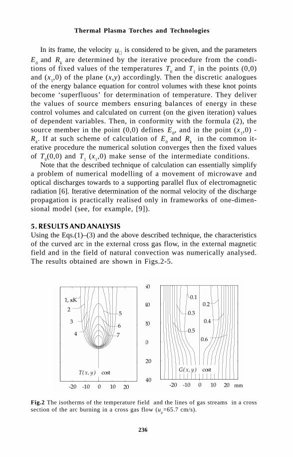
236
Thermal Plasma Torches and Technologies
In its frame, the velocity u∝ is considered to be given, and the parametersE
0 and R
k are determined by the iterative procedure from the condi-
tions of fixed values of the temperatures T0 and T
1 in the points (0,0)
and (x1,0) of the plane (x,y) accordingly. Then the discretic analogues
of the energy balance equation for control volumes with these knot pointsbecome ‘superfluous’ for determination of temperature. They deliverthe values of source members ensuring balances of energy in thesecontrol volumes and calculated on current (on the given iteration) valuesof dependent variables. Then, in conformity with the formula (2), thesource member in the point (0,0) defines E
0, and in the point (x
1,0) -
Rk. If at such scheme of calculation of E
0 and R
k in the common it-
erative procedure the numerical solution converges then the fixed valuesof T
0(0,0) and T
1 (x
1,0) make sense of the intermediate conditions.
Note that the described technique of calculation can essentially simplifya problem of numerical modelling of a movement of microwave andoptical discharges towards to a supporting parallel flux of electromagneticradiation [6]. Iterative determination of the normal velocity of the dischargepropagation is practically realised only in frameworks of one-dimen-sional model (see, for example, [9]).
- "$ ! $%Using the Eqs.(1)–(3) and the above described technique, the characteristicsof the curved arc in the external cross gas flow, in the external magneticfield and in the field of natural convection was numerically analysed.The results obtained are shown in Figs.2-5.
Fig.2 The isotherms of the temperature field and the lines of gas streams in a crosssection of the arc burning in a cross gas flow (u
µ=65.7 cm/s).
=
mm-20 -10 0 10 20-40
-20
0
20
40
60
=
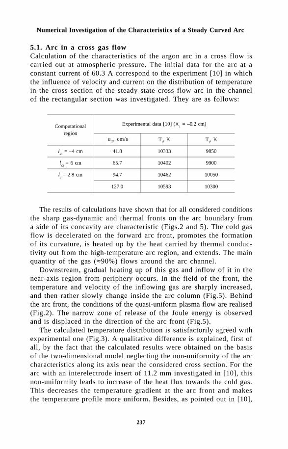
237
Numerical Investigation of the Characteristics of a Steady Curved Arc
5.1. Arc in a cross gas flowCalculation of the characteristics of the argon arc in a cross flow iscarried out at atmospheric pressure. The initial data for the arc at aconstant current of 60.3 A correspond to the experiment [10] in whichthe influence of velocity and current on the distribution of temperaturein the cross section of the steady-state cross flow arc in the channelof the rectangular section was investigated. They are as follows:
The results of calculations have shown that for all considered conditionsthe sharp gas-dynamic and thermal fronts on the arc boundary froma side of its concavity are characteristic (Figs.2 and 5). The cold gasflow is decelerated on the forward arc front, promotes the formationof its curvature, is heated up by the heat carried by thermal conduc-tivity out from the high-temperature arc region, and extends. The mainquantity of the gas (≈90%) flows around the arc channel.
Downstream, gradual heating up of this gas and inflow of it in thenear-axis region from periphery occurs. In the field of the front, thetemperature and velocity of the inflowing gas are sharply increased,and then rather slowly change inside the arc column (Fig.5). Behindthe arc front, the conditions of the quasi-uniform plasma flow are realised(Fig.2). The narrow zone of release of the Joule energy is observedand is displaced in the direction of the arc front (Fig.5).
The calculated temperature distribution is satisfactorily agreed withexperimental one (Fig.3). A qualitative difference is explained, first ofall, by the fact that the calculated results were obtained on the basisof the two-dimensional model neglecting the non-uniformity of the arccharacteristics along its axis near the considered cross section. For thearc with an interelectrode insert of 11.2 mm investigated in [10], thisnon-uniformity leads to increase of the heat flux towards the cold gas.This decreases the temperature gradient at the arc front and makesthe temperature profile more uniform. Besides, as pointed out in [10],
Computationalregion
Experimental data [10] (Χ1 = –0.2 cm)
u???
, cm/s T0, K T
1, K
lx1
= –4 cm 41.8 10333 9850
lx2
= 6 cm 65.7 10402 9900
ly = 2.8 cm 94.7 10462 10050
127.0 10593 10300
u ∝ , cm/s

238
Thermal Plasma Torches and Technologies
a
b
Fig.3 The temperature distributions (a) and (b) (u∝ = 65.7 cm/s): the solid lines arenumerical results, and × the experimental data [10].
for arcs with the current more than 20 A without the external crossflow, the asymmetry of isotherms are observed due to the influenceof the electrode jets. The own impulse of the electrode jets may alsolead to expansion of the high-temperature zone in the arc cross sec-tion. But the consideration of these effects does not qualitatively changethe flow picture.
The accuracy of the calculation results is also confirmed by agreementof the theoretical values of the arc current obtained from Eq.(3) withexperimental value of 60.3 A: 85 A for velocity 41.8 cm/s; 67 A for65.7 cm/s; 56 A for 94.7 cm/s; 60 A for 127 cm/s.
5.2. Arc in the mass force fieldsThe calculations of the characteristics of an argon arc in the externalmass force fields were carried out under the follows conditions:
a) the magnetic field rB B( , )0 under the action of the Ampere force
F EB Fx y= =σ , 0 where B is the induction of the field;b) the gravity field
rg g( , )− 0 under the action of the Archimed force
F g Fx y= − =∞( ) ,ρ ρ 0 where g is gravity acceleration.The initial data for calculations were the following: l
x1 = –3 cm, l
x2=
6 cm, ly = 3 cm, x
1= – 0.2 cm; T
0 = 9000 K, T
1 = 8000 K; B = 0.2 mTs.
As follows from the calculation results for these regimes, the commongas-dynamic patterns in the vertical cross section of the horizontal arcin the field of forces of Ampere and Archimedes are qualitatively thesame (Fig.4) but differ from the considered above one for the exter-nal gas flow. In the field of mass forces, the radial gas inflow in thedischarge from periphery is formed which further moves in the directionof curvature of the arc column.

239
Numerical Investigation of the Characteristics of a Steady Curved Arc
=
= g/s
mm
Fig.4 Isotherms of the temperature field and the gas flow lines in cross section of thearc burning in an external magnetic field (B = 0.2 mTs).
Fig.5 Variations of the temperature T, velocity u, difference of pressure p and currentdensity j of argon arcs burning in various conditions: 1 - external gas flow: u
µ = 65.7
cm/s, I = 67 A, Rk= 5.9 mm; 2 - external magnetic field: B = 0.2 mTs, I = 23 A, R
k =
5 mm; 3 - natural convection: I = 17 A, Rk = 5 mm.
Such flow pattern arises due to that the cross gas velocities are com-parable to velocity of the thermal wave (i.e. the gas has enough timeto be heated up) and that the negative pressure difference ∆p p p= − ∞
inside the arc is appeared. However, as for the external flow, the pressuredifference is positive before the forward arc front that limits a quantityof gas flowing into the discharge from a side of arc concavity. In thefield of the front, the temperature and velocity of inflowing gas arealso sharply increased. Further, already in the currentless region, a gascontinues to accelerate in the field of the Archimed force and beginsto decelerate in the field of the Ampere force.
. ) &$)/$ % ' 0 )1)") )&"The simple approach based on the theory of shock waves allows to

240
Thermal Plasma Torches and Technologies
consider the problem of estimation of plasma velocity in a high-temperaturezone of the discharge.
Let us assume that the cold gas flow has at infinity the mass densityρ∝ and velocity u∝ . The gas remains cold up to the front of the dis-charge. Along the zero gas stream line, the Bernoulli equation is ful-filled in the form
u p u12
122+ =∞ ∞δ ρ/ .
Here the index “1” corresponds to the parameters before the dis-charge front; δp1 is the pressure difference appearing in result of reducinggas velocity at the approach to the front. At transition of the flow behindthe discharge front, heating and ionization of gas takes place, and theregion of the quasi-uniform flow is realised with the temperature closeto maximum one inside the discharge and with density ρ
1 with the absence
of appreciable viscous forces and pressure difference.The thickness of the thermal and gas-dynamic boundary layer where
reorganisation of the flow takes place is small in comparison with thesize of the area of the quasi-uniform flow. We consider it as a shocksurface on which the conditions of preservation of the mass flow densitiesρ ρ∞ =u u1 0 0 , and components of flow momentum density ρ δ ρ∞ + =u p u1
21 0 0
2
are fulfilled.The above equations define the gas-dynamic parameters of the plasma
flow inside and before the discharge for the given parameters of thecold gas flow. Taking into account that ρ ρ0 << ∞ we have
u u u u p u0 01 2
1 01 2
122 2 2≈ ≈ =∞ ∞ ∞ ∞ ∞ ∞( / ) , ( / ) , // /ρ ρ ρ ρ δ ρ (4)
Note that for similar estimations in [3] the formula u u0 02= ∞ ∞( / )ρ ρgiving on the order exceeding values of plasma velocity inside an arcwas obtained.
The gas flow in the vertical cross section of a horizontal arc in thefield of gravity under action of the Archimedes force density f g= ∞ρis differently formed. The uniform plasma flow of extention L is causednow by joint action of the Archimedes force and negative pressure behindthe discharge front. Thus, similarly to the previous case, we have
u fL u fL p fL0 0 1 02
1 02 2 1 2= = = −∞ ∞/ , / , ( / ).ρ ρ ρ δ ρ ρ
Comparison of the calculated gas velocities in the zone of maximum
241
Numerical Investigation of the Characteristics of a Steady Curved Arc
isotherm of the arc with estimations of their values by the above mentionedmodel shows the follows. For the regime with the external gas flowwith u∝ =0.418 m/s and u∝ =1.27 m/s, formula (4) gives the values ofvelocities 1.77 m/s and 5.49 m/s that well correlate with calculated values2.78 m/s and 6.07 m/s accordingly. For the regime in which naturalconvection is taken into account, the model estimation of the plasmavelocity about 1.93 m/s is close to the value of 1.97 m/s from numericalcalculation.
References1 M.F.Zhukov, et al, Theory of Thermal Electric Arc Plasma, Vol.1, Methods
of mathematical investigation of plasmas, (in Russian), Novosibirsk,Nauka (1987).
2 O.Ya.Novikov, Stability of electric arc, (in Russian), Publ. Energy, Leningrad(1978).
3 H.Maecker, Proc. IEEE, 4, 4-14 (1971).4 G.A.Desyatkov, et al, J. High Temperature Chem. Processes, 1, No.3,
291-298 (1992).5 G.A.Desyatkov, et al, Proc. of 10th Intern. Symp. on Plasma Chemis-
try, Bochum, Germany, Vol.1 (1991) pp.1.1-24.6 Yu.P.Raizer, Physics of gas discharge, (in Russian), Publ Nauka, Moscow
(1987).7 N.Sebald, J. Appl. Phys, 21, 221-236 (1980).8 S.Patankar, Numerical methods of solution of problems of heat exchange
and hydrodynamics, (in Russian), Energoatomizdat Moscow (1984).9 J.P.Kneht and M.M.Michi, AST, No.1, 133-140 (1989).1 0 D.M.Benenson and A.A.Tsenkner, Teploperedacha, (in Russian), No.2,
69-77 (1970).

242
Thermal Plasma Torches and Technologies
Milan Hrabovský, Miloš Konrád, Vladimír Kopecký andViktor Sember
Institute of Plasma Physics, Academy of Sciences of Czech Republic,182 21 Prague 8, Czech Republic
Abstract: Plasma torches with water stabilized arcs provide an alternativeto commonly used sources of thermal plasmas based on gas-stabilized arcsor RF discharges. Relatively long arc columns can be stabilized by waterwalls under very low mass flow rates through the torch chamber. This leadsto high values of plasma temperature and enthalpy. In water-stabilized torches,an oxygen-hydrogen plasma jet is produced with extremely high plasma enthalpyand flow velocity. Plasma torches with the water-stabilized arc provide specialperformance characteristics in some plasma processing applications like plasmaspraying or waste treatment. Physical processes which determine the propertiesof generated plasma are discussed and basic characteristics of the water plasmatorch are presented.
Thermal plasmas are commonly generated in inductively coupled dischargesor in electric arcs which are stabilized by the gas flow. Typically, inductivelycoupled plasma torches are characterized by plasma temperatures from6 000 K to 10 000 K. Averaged temperatures in torches with non-transferredelectric arcs with gas stabilization are somewhat higher, usually in therange from 8 000 K to 14 000 K. Average plasma enthalpies, determinedas the ratio of the useful power of the plasma generator to the flow rateof the plasma forming gas, vary from 1 to 100 MJ/kg. Further increaseof plasma temperatures and enthalpies is limited by the fact that theflowing gas protects the arc chamber walls from thermal overloadingand a minimum possible gas flow rate thus exists for the given arc power.

243
Properties of Water-Stabilized Plasma Torches
Higher thermal loading is possible if the walls are created by water andan arc is stabilized by wall evaporation. Thus, water-stabilized arcs canbe utilized as sources of thermal plasma with high temperatures andenthalpies.
The electric arc with stabilization of the arc column by the watervortex was first described more than seventy years ago by Gerdien andLotz [1] [2]. Basic experimental investigations of the water-stabilizedarcs were performed in the 1950´s. Maecker et al. [3,4] measured basicelectric characteristics of the arc and studied the effect of the lengthand diameter of the stabilizing channel. Several investigators measuredarc plasma temperatures using methods of emission spectroscopy [5]-[7]. All authors reported very high plasma temperatures in the arc columnwith maximum about 50 000 K in the centerline position. The princi-ple of arc stabilization by the water vortex was utilized in the plasmatorch designed for plasma spraying and cutting [8]. Despite the pos-sibility of achieving extreme performance characteristics, the developmentof water-stabilized torches has been limited especially due to their morecomplex structure and due to the lack of understanding of physical processesin the arc which is necessary for improvement of the torch design.
The investigation of water-stabilized plasma torches started severalyears ago with the aim of better understanding of the arc processes,development of plasma torches and determination of the characteristicsof the generated plasma jet. Some basic results of this investigation arepresented. Differences between water- and gas-stabilized torches are discussedand experimental characteristics of water-stabilized arc and of the generatedplasma jet are shown. The performance characteristics of water-stabilizedtorch in applications like plasma spraying are presented.
!""!"#$%$&$$$'$%(!%!$'$$!To estimate the effect of the material properties of the plasma gas aswell as of the effect of dimensions of the arc chamber on the arccharacteristics, we derive simple equations for the basic characteristicsof the arc column, which can be applied on both liquid- and gas-stabilizedarcs in a cylindrical chamber of the plasma torch. The integral energybalance equation of a cylindrical arc column can be written in the form[9]
Ar
TkREARmh
z
Ahvn
Rr
z επ∂∂πσ
∂ρ∂
42)()( 2 −
+=−
= (1)
where r is plasma density, vz axial velocity, h enthalpy, s electric conductivity,

244
Thermal Plasma Torches and Technologies
k thermal conductivity, T temperature, en net emission coefficient representing
power loss due to radiation and E electric field intensity. A = p R2 isthe cross section of the arc chamber with radius R, m is the mass flowrate from the chamber walls per unit length, r and z are the radial andaxial coordinates. The equation (1) was obtained from the energy balanceequation of a cylindrical arc column by integrating over the cross sectionof the arc chamber. The quantities averaged over the cross section Aare defined by the equation
∫=R
rXdrR
X0
22
1 ππ (2)
A simple equation can be obtained if derivatives in equation (1) areapproximated as
L
Ahv
z
Ahv zz ρ∂
ρ∂ =)(, R
S
R
S
r
Tk
Rr
−==
=
∂∂
∂∂
(3)
where L is length of the arc chamber and heat flux potential S is definedas
∫=T
T
dTkS0
(4)
Enthalpy h(R) of vapour flowing from the wall into the arc chambercorresponds to the boiling temperature of water T
B and can be put equal
to zero h(R) = h (TB) = 0. The integral energy balance equation can
be then written in the form
σπσπεππ
2
2222242
R
IERRS
L
hGn ==++ (5)
where arc current I and total mass flow rate G are given by the equations
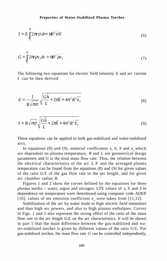
245
Properties of Water-Stabilized Plasma Torches
ERdrrEIR
σπσπ 2
0
2 == ∫ (6)
z
R
z vRdrvrG ρπρπ 2
0
2 == ∫ (7)
The following two equations for electric field intensity E and arc currentI can be then derived
nRSL
hG
RE εππ
σπ2242
1 ++= (8)
nRSL
hGRI εππσπ 2242 ++= (9)
These equations can be applied to both gas-stabilized and water-stabilizedarcs.
In equations (8) and (9), material coefficients s, h, S and en
whichare dependent on plasma temperature, R and L are geometrical designparameters and G is the total mass flow rate. Thus, the relation betweenthe electrical characteristics of the arc I, E and the averaged plasmatemperature can be found from the equations (8) and (9) for given valuesof the ratio G/L of the gas flow rate to the arc length, and for givenarc chamber radius R.
Figures 1 and 2 show the curves defined by the equations for threeplasma media – water, argon and nitrogen. LTE values of s, h and S independence on temperature were determined using computer code ADEP[10], values of net emission coefficient e
n were taken from [11,12].
Stabilization of the arc by water leads to high electric field intensitiesand thus high arc powers, and also to high plasma enthalpies. Curvesin Figs. 1 and 2 also represent the strong effect of the ratio of the massflow rate to the arc length G/L on the arc characteristics. It will be shownin part 5 that the main difference between the gas-stabilized and wa-ter-stabilized torches is given by different values of the ratio G/L. Forgas-stabilized torches, the mass flow rate G can be controlled independently,
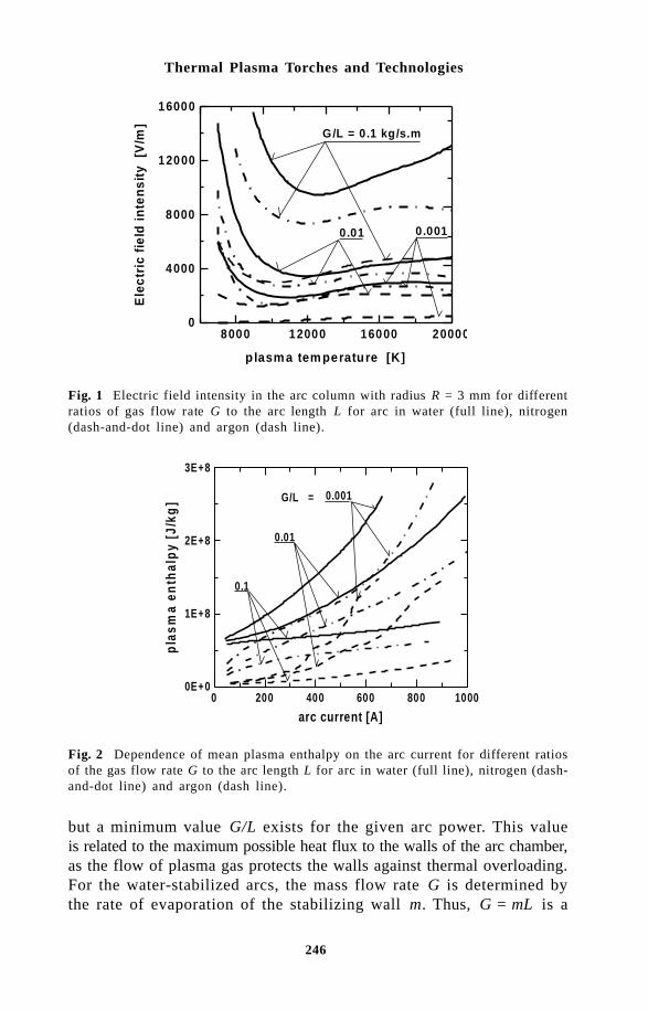
246
Thermal Plasma Torches and Technologies
8000 12000 16000 20000
plasm a tem perature [K]
0
4000
8000
12000
16000
Ele
ctri
c fi
eld
in
ten
sity
[V
/m]
0 .0010.01
G/L = 0.1 kg/s.m
Fig. 1 Electric field intensity in the arc column with radius R = 3 mm for differentratios of gas flow rate G to the arc length L for arc in water (full line), nitrogen(dash-and-dot line) and argon (dash line).
0 200 400 600 800 1000
arc current [A]
0E+0
1E+8
2E+8
3E+8
pla
sma
enth
alp
y [J
/kg
] G/L = 0.001
0.01
0.1
Fig. 2 Dependence of mean plasma enthalpy on the arc current for different ratiosof the gas flow rate G to the arc length L for arc in water (full line), nitrogen (dash-and-dot line) and argon (dash line).
but a minimum value G/L exists for the given arc power. This valueis related to the maximum possible heat flux to the walls of the arc chamber,as the flow of plasma gas protects the walls against thermal overloading.For the water-stabilized arcs, the mass flow rate G is determined bythe rate of evaporation of the stabilizing wall m. Thus, G = mL is a

247
Properties of Water-Stabilized Plasma Torches
parameter, which is given by the balance of radial heat transfer in thearc chamber. Long arc columns at low mass flow rates can be stabi-lized in water and thus very low values of G/L can be achieved in thewater stabilized arcs. In part 4, processes controlling the mass flow ratewill be analyzed.
) #!" $(#*$"$(+$!A schematic picture of a water-stabilized arc is shown in Fig. 3. Anarc is ignited in the center of a vortex of water which is created in thearc chamber by means of tangential water injection. Water flows overthe segment, which determines the inner diameter of the vortex, into theexhaust slot. Evaporation from the inner surface of the vortex and heatingand ionization of vapour are principal mechanisms that produce arc plasma.The energy, dissipated in the conducting arc core by Joule heating, istransported radially to the inner surface of the vortex by radiation, heatconduction and turbulent transfer. Evaporation rate m is determined bya fraction of total power reaching the liquid. The other part of transferredenergy is absorbed in a vapour zone (between the arc column and thesurface of water) causing heating and ionization of vapour. A part ofthe energy which is transferred into the liquid represents power loss Q.Thus, the balance of radial heat transfer is decisive for the value ofm, which affects all characteristics of the arc. This balance is analyzedin the following part on the basis of experimental results.
vapour zone
I· E m cathode
liquid vortex anode
Q
tangential water inlet
water outlet
exit nozzle
arc
Fig. 3 Schematics of liquid stabilized arc.
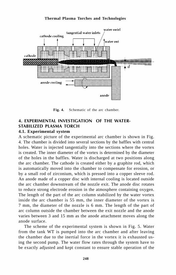
248
Thermal Plasma Torches and Technologies
d
Fig. 4. Schematic of the arc chamber.
, !-!%!$# .!&$ " '!$! $(#*! #$%$ '4.1. Experimental systemA schematic picture of the experimental arc chamber is shown in Fig.4. The chamber is divided into several sections by the baffles with centralholes. Water is injected tangentially into the sections where the vortexis created. The inner diameter of the vortex is determined by the diameterof the holes in the baffles. Water is discharged at two positions alongthe arc chamber. The cathode is created either by a graphite rod, whichis automatically moved into the chamber to compensate for erosion, orby a small rod of zirconium, which is pressed into a copper sleeve rod.An anode made of a copper disc with internal cooling is located outsidethe arc chamber downstream of the nozzle exit. The anode disc rotatesto reduce strong electrode erosion in the atmosphere containing oxygen.The length of the part of the arc column stabilized by the water vortexinside the arc chamber is 55 mm, the inner diameter of the vortex is7 mm, the diameter of the nozzle is 6 mm. The length of the part ofarc column outside the chamber between the exit nozzle and the anodevaries between 3 and 15 mm as the anode attachment moves along theanode surface.
The scheme of the experimental system is shown in Fig. 5. Waterfrom the tank WT is pumped into the arc chamber and after leavingthe chamber due to the inertial force in the vortex it is exhausted us-ing the second pump. The water flow rates through the system have tobe exactly adjusted and kept constant to ensure stable operation of the

249
Properties of Water-Stabilized Plasma Torches
Fig. 5. Experimental system. WT – water tank, q – flow meter, T – thermometer,RB – bias resistance, VD – voltage divider, S – shunt, PS – power source, EN -exit nozzle, A – anode, C – cathode, P1, P2 – electric probes.
torch. The flow rates and temperatures are measured both at the inputand at the output of the arc chamber and the anode. Arc voltage andthe potential of the exit nozzle were measured using voltage dividersVD, for arc current measurement shunt S was connected in the cath-ode part of the circuit. For measurement of the plasma potential at theposition of the exit nozzle, the high resistance divider has to be usedto measure the floating plasma potential.
Electric probes P1 and P2 were applied for the measurement of plasmaflow velocity. The probes were negatively biased by connecting to thecathode through the bias resistance R
B, i.e., they were in the ion col-
lecting regime. For low values of the bias resistance, the probe potentialwas given by the ion saturation current and thus it was highly sensi-tive to the plasma properties in the position of the probe tip. In thisregime, the probe signal exhibited intensive fluctuations as plasma dis-turbances passed along the probe. From the correlation of signals oftwo probes located in different axial positions along the plasma jet thevelocity of movement of plasma disturbances could be evaluated, whichis supposed to characterize the velocity of the plasma flow. To reducethe probe erosion, the probes were moved across the plasma jet withthe velocity that was small compared to the plasma velocity. The probemeasurements are described more in detail in [13,14].
The temperature of the plasma was measured by optical emissionspectroscopy. The Jobin Yvon OMA system used for spectroscopicdiagnostics consists of a grating monochromator HR-320 (Czerny-Turner

250
Thermal Plasma Torches and Technologies
L A BE PJ
L
SC
Fig. 6. Schematic setup for Schlieren photography. LA-pulsed Nd laser, BE-beamexpander, PJ-plasma jet, L-lens f=1500 mm, S-Schlieren stop, C-camera.
configuration, f = 0.32 m) fitted with the linear photodiode array de-tector RY/1024, a control device and a personal computer. The Imageof the plasma jet was transversely scanned by means of an optical standwith an optical fibre, giving a spatial resolution about 0.1 mm. In thisway time-averaged radial intensity profiles were obtained [15–17].
The structure of the flow field of the plasma jet was visualized byschlieren photography. In the focus of the lens a circular stop was placedso only deflected rays were imaged by the camera (Fig. 6).
4.2. Measured characteristics of the water stabilized torchThe volt–ampere characteristics of the arc are shown in Fig. 7. Arc voltageU
a and the potential difference between the cathode and the exit nozzle
Ue are plotted against the arc current. The measurements were made
for several positions d of the anode with respect to the axis of the nozzle(see Fig. 4). The averaged values of arc voltage are shown as well asminimum values during the saw tooth-shaped fluctuations of arc voltage
Fig. 7. Volt–ampere characteristics of the arc for several distances d of anode fromthe nozzle axis. Ua,min - minimum value of arc voltage, Ua,av – mean value of arcvoltage, U
e - potential of the exit nozzle.
350 400 450 500 550 600 650160
200
240
280
320
360
Ue
[m m ] =
6
5
4
3
Ua , m in
Ua , a v

251
Properties of Water-Stabilized Plasma Torches
caused by movement of anode attachment [18]. It can be seen that thetotal arc voltage depends on the position of anode as the length of thearc column between the nozzle exit and the anode attachment is influencedby d. The potential of the nozzle U
e is not affected by d.
The power balance of the arc (Fig. 8) was evaluated from the electriccharacteristics of the arc and from calorimetric measurements on thestabilizing water system. Total power input W
T is plotted as well as the
power input Wc into the part of the arc column stabilized by the wa-
ter vortex. The other characteristics of the stabilized part of the arccolumn are the power loss to water P
w and total enthalpy flux F
e through
the exit nozzle.The temperature in the water plasma jet was determined from the
analysis of the results obtained by different spectroscopic methods, includingthe Boltzmann plot of OII lines in the spectral region 370–475 nm, differentratios of the relative emission coefficients of OI lines in the IR spec-tral region, hydrogen Balmer H
b and some OII lines, and Stark broadening
of Hb line. A typical sample of the radial distribution of emission spectrum
in the region around Hb line is shown in Fig. 9. Evaluation and inter-
pretation of the spectroscopic data was based mostly on the assump-tion of LTE and cylindrical symmetry. Nevertheless, deviations from LTE,resulting from both the presence of steep temperature and density gradients,and high velocity of the plasma flow, as well as from the cylindricalsymmetry due to anode arc root attachment occurring outside the mainplasma jet, were also investigated [16,17].
The distribution of the relative emission coefficients was obtainedwith the help of asymmetrical Abel inversion based on the assumption
350 400 450 500 550 600 650current [A]
0
40
80
120
160
200
po
wer
[kW
]
Wt
W c
Fe
Pw
Pa
d = 3 m m
d = 5 m m
d = 6 m m
Fig. 8. Power balance of the arc for several positions of anode. WT – total power
input, Wc – power input into stabilized part of the arc column, P
w – power loss to
the water vortex, Pa – power loss to the anode, F
e – total enthalpy flux through the
exit nozzle.

252
Thermal Plasma Torches and Technologies
λ
ε λ
β
Fig. 9. Radial distribution of emission coefficient ε(λ ,r) in the spectral region withH
b line (486.13 nm) and several OII lines.
that the plasma column keeps a cylindrical shape within which an asymmetricdistribution of radiation, and hence temperature and density, exists onlynormal to the direction of observation [19]. Deviations from LTE wereexamined using the close-to-LTE concept that describes the departureof excited state populations form their LTE values by means of nonequilib-rium factors which are defined as the ratio of the true state populationdensity to that given by equilibrium relations. The nonequilibrium factorswere obtained by comparing the measured ratio of line and underlyingcontinuum emission coefficients with that calculated using the upper levelSaha equation in case of an atomic line and the Boltzmann distribu-tion in case of an ionic line. To take into account the reabsorption ofspectral lines, an iterative computational procedure based on the ‘op-tically thick’ integral equation for spectral intensities was applied tosimulate the measured line-to-continuum ratio [20].
It has turned out, among others, that a significant underpopulationof atomic and ionic excited states can be expected, having a strong impacton the energy balance in the plasma jet, which can explain, at least partially,why measured temperatures do not agree sufficiently with the predic-tions of the present numerical model of the water plasma jet [21] thatis likely to overestimate radiation losses [22].
Based on this analysis, the temperature distribution in the laminarpart of the plasma jet was derived. On the other hand, this approachfailed in fringes and the region near the arc anode attachment due tothe strong departure from LTE and quasi-cylindrical symmetry used foran evaluation of the Abel inversion. The resulting radial profiles of tem-perature at the position 2 mm downstream of the nozzle exit are shownin Fig. 10 for several values of arc current [17].
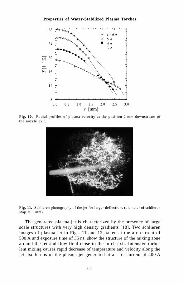
253
Properties of Water-Stabilized Plasma Torches
0 .0 0 .5 1 .0 1 .5 2 .0 2 .5 3 .08
1 2
1 6
2 0
2 4
2 8
Fig. 10. Radial profiles of plasma velocity at the position 2 mm downstream ofthe nozzle exit.
The generated plasma jet is characterized by the presence of largescale structures with very high density gradients [18]. Two schlierenimages of plasma jet in Figs. 11 and 12, taken at the arc current of500 A and exposure time of 35 ns, show the structure of the mixing zonearound the jet and flow field close to the torch exit. Intensive turbu-lent mixing causes rapid decrease of temperature and velocity along thejet. Isotherms of the plasma jet generated at an arc current of 400 A
Fig. 11. Schlieren photography of the jet for larger deflections (diameter of schlierenstop = 5 mm).

254
Thermal Plasma Torches and Technologies
are shown in Fig. 13, development of the centerline velocity along thejet is shown in Fig. 14. The velocities were determined from the timeshift of signals of two probes corresponding to the time of flight of plasmadisturbances [13,14]. The high level of correlation of the signals wasfound by the statistical analysis of measured signals for probe distancesup to 7 mm from the torch exit. Plasma flow velocities close to the nozzleexit are higher than 1 km/s and are strongly influenced by the arc current.Despite of their rapid decrease with increasing distance from the nozzleexit, both the temperature and the velocity are high in the jet.
4.3. Analysis of power and mass balances in the arc chamberThe basic physical processes in the arc chamber are processes controllingthe radial and axial transport of energy dissipated in the arc columnby Joule heating. The energy and mass balances in the stabilizing channelare shown schematically in Fig. 15. Part Q
R of power IE dissipated in
the conducting arc core by Joule heating is transported radially to theinner wall of the water vortex. Here it causes evaporation of mass mof water. The rest of power Q
W is absorbed either in the body of water
or in the walls of arc chamber. Principal mechanisms involved in theradial transport of energy from the conducting core through the sheathof vapour to the water wall are radiation, heat conduction and turbulenttransfer. Radiative heat transfer is the decisive mechanism for very highplasma temperatures achieved in the water torch. The total radiative lossfrom the unit length of the arc column can be expressed by the empiricalrelationship [23]
Fig. 12. Schlieren photography of the jet region close to the torch exit for smallerdeflections (diameter of schlieren stop = 1 mm).
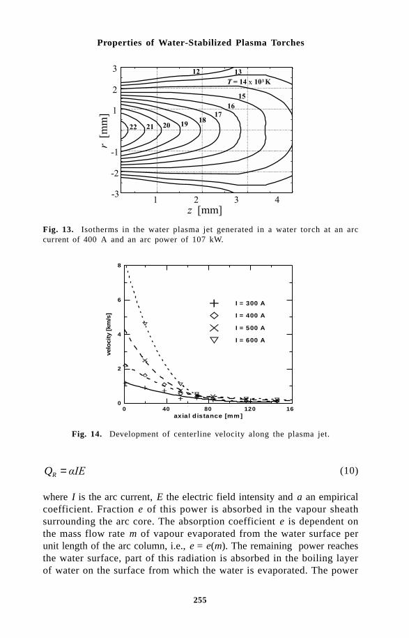
255
Properties of Water-Stabilized Plasma Torches
!"#$
#
Fig. 13. Isotherms in the water plasma jet generated in a water torch at an arccurrent of 400 A and an arc power of 107 kW.
0 40 80 120 16axial d istance [mm ]
0
2
4
6
8
velo
city
[km
/s]
I = 300 A
I = 400 A
I = 500 A
I = 600 A
Fig. 14. Development of centerline velocity along the plasma jet.
QR = (10)
where I is the arc current, E the electric field intensity and a an empiricalcoefficient. Fraction e of this power is absorbed in the vapour sheathsurrounding the arc core. The absorption coefficient e is dependent onthe mass flow rate m of vapour evaporated from the water surface perunit length of the arc column, i.e., e = e(m). The remaining power reachesthe water surface, part of this radiation is absorbed in the boiling layerof water on the surface from which the water is evaporated. The power
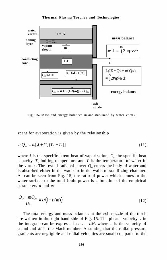
256
Thermal Plasma Torches and Technologies
watervortex
vapoursheath
conductingcore
m
mass balance
energy balance
exitnozzle
boilinglayer
I .E
α .IE.1-ε(m)
Qw = α .IE.1-ε(m)-m.Qev
QR=αIE
= ∫
π ρ
= ∫
πρ
− − =
T = T0
T = TB
spent for evaporation is given by the relationship
)]([ 0TTCmmQ Bwev −+= λ (11)
where l is the specific latent heat of vaporization, Cw the specific heat
capacity, TB boiling temperature and T
0 is the temperature of water in
the vortex. The rest of radiated power Qw enters the body of water and
is absorbed either in the water or in the walls of stabilizing chamber.As can be seen from Fig. 15, the ratio of power which comes to thewater surface to the total Joule power is a function of the empiricalparameters a and e:
( ))(1 mIE
mQQ evw εα −=+ (12)
The total energy and mass balances at the exit nozzle of the torchare written in the right hand side of Fig. 15. The plasma velocity v inthe integrals can be expressed as v = cM, where c is the velocity ofsound and M is the Mach number. Assuming that the radial pressuregradients are negligible and radial velocities are small compared to the
Fig. 15. Mass and energy balances in arc stabilized by water vortex.

257
Properties of Water-Stabilized Plasma Torches
axial velocity, the Mach number can be assumed to be independent ofthe radial co-ordinate at the exit nozzle. This assumption is often ap-plied in the description of high current arcs in nozzle flows [24]. Thefollowing equations for Mach number M and evaporation rate m canbe then derived:
( )
∫ ∫−++
−=E ER R
Bw
w
drcrTTCdrchr
QIELM
0 0
0 2)]([2 ρπλρπ (13)
drcrMmLER
ρπ∫=0
2 (14)
where r is plasma density, h enthalpy, L the length of the arc columnand R
E the radius of the exit nozzle. The integrals in equations (13)
and (14) can be determined from the measured temperature profiles andfrom the transport and thermodynamic coefficients of arc plasma assumingthe existence of LTE [25]. Thus, Mach number M and mass flow ratem can be evaluated from measured temperature profiles at the nozzleexit and from the power balance of the arc chamber. The values of theMach number and the mass flow rate evaluated from the results ofmeasurements are shown in Fig. 16 in dependence on arc current. Fromthe values of M, the ratio of stagnation pressure inside the arc chamberto the atmospheric pressure p/p
0 can be evaluated. This ratio was derived
assuming that the temperature along the arc column is constant. Forthe isothermal flow, the pressure ratio is given by the equation
( )κ2exp 20 Mpp = (15)
where κ is the adiabatic coefficient of water plasma. The dependenceof the pressure ratio on the arc current is also presented in Fig. 16.
Knowing the value of Mach number, the velocity profile can be derivedfrom the measured temperature profile using relation v(r) = Mc[T(r)]where the velocity of sound c is the function of temperature for equi-librium conditions in plasma. The pressure at the nozzle exit was supposedto be equal to the atmospheric pressure. As the maximum of the pressureratio given by equation (15) was relatively low (see Fig. 16) and thedependence of the sound velocity on pressure is weak, the possible error

258
Thermal Plasma Torches and Technologies
Fig. 16. Mach number M, evaporation rate m and pressure ratio p/p0 in dependence
on arc current.
0 .0 1 .0 2 .0 3 .00
2 0 0 0
4 0 0 0
6 0 0 0
8 0 0 0
➀
➁
➂
➃
➀➁➂➃
!"#$%
Fig. 17. Radial profiles of plasma velocity at the position 2 mm downstream ofthe nozzle exit.
in estimation of pressure has no effect on the resulting values of ve-locity. The evaluated velocity profiles are shown in Fig. 17. Plasmavelocities are high compared to the velocities commonly reported forgas-stabilized plasma torches. The velocities at r = 0 can be comparedwith the velocities of plasma disturbances determined from the probemeasurements shown in Fig. 14. Measured velocities at Fig. 14 are somewhatlower than the plasma velocities determined from the temperature profiles,with the exception of values for I = 600 A.
In Fig. 18 the values of the left hand side term of equation (12) areplotted against m. The values of the quantities in (12) were determined
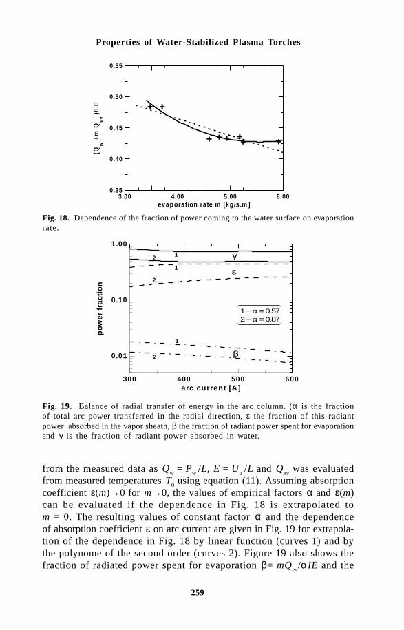
259
Properties of Water-Stabilized Plasma Torches
Fig. 18. Dependence of the fraction of power coming to the water surface on evaporationrate.
Fig. 19. Balance of radial transfer of energy in the arc column. (α is the fractionof total arc power transferred in the radial direction, ε the fraction of this radiantpower absorbed in the vapor sheath, β the fraction of radiant power spent for evaporationand γ is the fraction of radiant power absorbed in water.
from the measured data as Qw = P
w /L, E = U
a /L and Q
ev was evaluated
from measured temperatures T0 using equation (11). Assuming absorption
coefficient ε(m)→0 for m→0, the values of empirical factors α and ε(m)can be evaluated if the dependence in Fig. 18 is extrapolated tom = 0. The resulting values of constant factor α and the dependenceof absorption coefficient ε on arc current are given in Fig. 19 for extrapola-tion of the dependence in Fig. 18 by linear function (curves 1) and bythe polynome of the second order (curves 2). Figure 19 also shows thefraction of radiated power spent for evaporation β= mQ
ev/αIE and the
3.00 4.00 5.00 6.00evaporation rate m [kg/s.m ]
0.35
0.40
0.45
0.50
0.55
(Qw
+m.Q
ev )/
I.E
300 400 500 600arc current [A ]
0.01
0.10
1.00
po
wer
fra
ctio
n
1 − α = 0.572 − α = 0.87
12 γ
ε
β
1
2
1
2

260
Thermal Plasma Torches and Technologies
fraction of radiated power absorbed in the water γ = Qw/αIE. Most of
the radiation is absorbed in the water and contributes to the power loss,about 0.2–0.5 of radiation power is absorbed in the vapour sheath andcontributes to the heating of vapour, and only 0.01–0.02 of radiationpower is spent on evaporation from the water surface. The fraction ofthe total power spent on evaporation is then βα ≈ 0.007–0.01. This verylow fraction of total arc power spent on the production of the plasmagas is the main cause of extremely high plasma temperatures andvelocities accompanied by the low mass flow rate through the exit nozzle.
/%$"$! $(#*!$&$ $(#*!'!The basic characteristics of the plasma jet, evaluated from measurements(see part 4) carried out on the water-stabilized plasma torch operatingat a power up to 176 kW, are summarized in Table 1. In addition, thecharacteristic frequencies of the production of turbulent eddies due toentrainment of cold gas into the jet are given. The frequencies weredetermined from the power spectra of emitted light from the jet [26].High characteristic frequencies are related to high plasma flow velocities.The non-dimensional frequencies given by Strouhal number St = fD/v
m
are close to the values found in jets produced in gas stabilized torcheswith substantially lower flow velocities.
The values given in Table 1 are related to the nozzle exit. As thereis a part of the arc further downstream of the nozzle (between the nozzleand the external anode), some additional energy is dissipated into thejet, so the total enthalpy is somewhat higher than the one in Table 1.
The comparison of the operation regimes of the water-stabilized torchwith the regimes of conventional gas-stabilized torches and the high powertorch PlazJet (produced by TAFA) is shown in Fig. 20. The values forthe conventional gas-stabilized torches were determined from the datagiven in [27].
The water torch is characterized by a very low mass flow rate anda high arc power. These characteristics are connected with the principleof stabilization of the arc by the water wall. Comparison of the typi-cal parameters of the water-stabilized torch with the characteristics oftwo commercially available gas-stabilized plasma torches is given inTable 2.
The values of the mean plasma enthalpy and mean temperature forthe gas-stabilized torches were estimated assuming torch efficiency equals60%. The thermodynamic properties of plasma gases were calculatedon the basis of computer code and database ADEP [10]. The values for
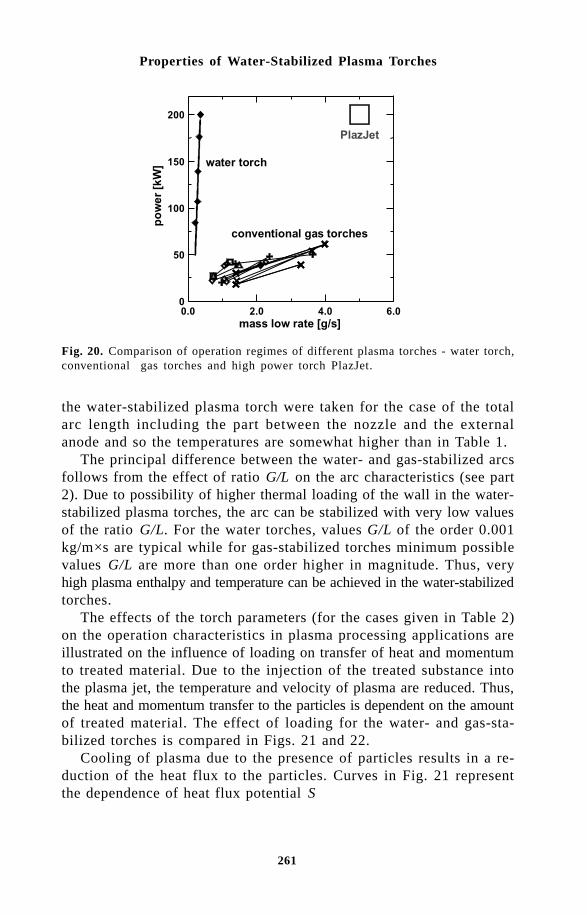
261
Properties of Water-Stabilized Plasma Torches
the water-stabilized plasma torch were taken for the case of the totalarc length including the part between the nozzle and the externalanode and so the temperatures are somewhat higher than in Table 1.
The principal difference between the water- and gas-stabilized arcsfollows from the effect of ratio G/L on the arc characteristics (see part2). Due to possibility of higher thermal loading of the wall in the water-stabilized plasma torches, the arc can be stabilized with very low valuesof the ratio G/L. For the water torches, values G/L of the order 0.001kg/m×s are typical while for gas-stabilized torches minimum possiblevalues G/L are more than one order higher in magnitude. Thus, veryhigh plasma enthalpy and temperature can be achieved in the water-stabilizedtorches.
The effects of the torch parameters (for the cases given in Table 2)on the operation characteristics in plasma processing applications areillustrated on the influence of loading on transfer of heat and momentumto treated material. Due to the injection of the treated substance intothe plasma jet, the temperature and velocity of plasma are reduced. Thus,the heat and momentum transfer to the particles is dependent on the amountof treated material. The effect of loading for the water- and gas-sta-bilized torches is compared in Figs. 21 and 22.
Cooling of plasma due to the presence of particles results in a re-duction of the heat flux to the particles. Curves in Fig. 21 representthe dependence of heat flux potential S
Fig. 20. Comparison of operation regimes of different plasma torches - water torch,conventional gas torches and high power torch PlazJet.
!

262
Thermal Plasma Torches and Technologies
Table 1 Water-stabilized torch operating parameters and jet exit condtions
arc current (A) 300 400 500 600 power input (kW) 84 106.8 139 176 mass flow rate (g/s) 0.204 0.272 0.285 0.325 mean temperature (K) 13 750 14 500 15 400 16 200 centerline temperature (K) 19 000 23 000 26 200 27 200 mean enthalpy (MJ/kg) 157 185 230 272 mean velocity (m/s) 1 736 2 635 3 247 4 230 centerline velocity (m/s) 2 494 4 407 5 649 7 054 mean density (kg/m3) 4.15x10⁻³ 3.64x10⁻³ 3.1x10⁻³ 2.72x10⁻³ centerline density (kg/m3) 1.92x10⁻³ 1.23x10⁻³ 0.98x10⁻³ 0.92x10⁻³ mean density ratio S 0.0034 0.0030 0.0026 0.0023 characteristic frequency (kHz) 52 68 96 118 Strouhal number St 0.18 0.15 0.18 0.17 Reynolds number Re 473 786 1 140 1 770 Mach number M 0.317 0.445 0.505 0.617
0.0 0.2 0.4 0.6 0.8 1.0fraction of jet power spent for powder heating
1E+3
1E+4
1E+5
hea
t fl
ux
po
ten
tial
[W
/m]
water
Ar/H2(33/10 slm ) 25 kW
Ar/H2(65/3 slm ) 43.5 kW
N2/H2(235/94 slm) 200 kW
176 kW
84 kW
∫=p
w
T
T
w dTTkTS )()( (16)
on the fraction of jet power available for particle heating. Here Tw
=1000 K is the particle surface temperature, T
p the plasma temperature
and k the thermal conductivity of plasma. The heat flux to particles isgiven by the relation
)( wp TSdNuQ π⋅= (17)
Fig. 21 Heat flux potential S in dependence on fraction of jet power available forparticle heating.

263
Properties of Water-Stabilized Plasma Torches
1 10 100powder m ass flow rate [kg/hour]
10
100
1000
10000
vel
oci
ty [
m/s
]
N 2/H 2(235 /94 slm ) 200 kW
water176 kW water
84 kW
A r/H 2(33/10 slm ) 25 kW
A r/H 2(65/3 slm ) 43.5 kW
where dp is the particle diameter and Nu the Nusselt number. The power
available for particle heating was determined as
)( pThGPQ −=η (18)
where P is the torch power, h is its efficiency, G the mass flow rateof the plasma gas and h(T
p) the plasma enthalpy at temperature T
p. The
curves were determined from the characteristics of different plasma torches(see Table 2). The efficiency of utilizing the jet power for powder heatingis substantially higher for the water torch and very high heat fluxes tothe particles can be achieved. The effect of particle loading on plasmavelocity is illustrated in Fig. 22.
The velocity of plasma and, consequently, the velocity of particlesare reduced when the powder mass flow rate is increased. The load-ing effect on the plasma velocity v
p is represented by the curves de-
termined from the balance of the momentum flux in the plasma jet:
pexit vMGGv )( += (19)
where G is the mass flow rate of plasma, vexit
the mean plasma velocityat the torch exit and M the powder mass flow rate. The curves weredetermined from the characteristics of different plasma torches (see Table2). The effect of particle loading on plasma velocity for water plasma
Fig. 22. The dependence of plasma velocity vp on powder mass flow rate.
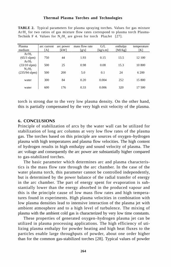
264
Thermal Plasma Torches and Technologies
TABLE 2. Typical parameters for plasma spraying torches. Values for gas mixtureAr/H2 for two ratios of gas mixture flow rates correspond to plasma torch Plasma-Technik F 4. Values for N2/H2 are given for torch PlazJet [27].
Plasma medium
arc current [A]
arc power [kW]
mass flow rate [g/s]
G/L [kg/s.m]
enthalpy [MJ/kg]
temperature [K]
Ar/H2
(65/3 slpm)
750
44
1.93
0.15
13.5
12 100 Ar/H2
(33/10 slpm)
500
25
0.98
0.08
15.3
10 800 N2/H2
(235/94 slpm)
500
200
5.0
0.1
24
6 200
water
300
84
0.20
0.004
252
15 800
water
600
176
0.33
0.006
320
17 500
torch is strong due to the very low plasma density. On the other hand,this is partially compensated by the very high exit velocity of the plasma.
0#Principle of stabilization of arcs by the water wall can be utilized forstabilization of long arc columns at very low flow rates of the plasmagas. The torches based on this principle are sources of oxygen–hydrogenplasma with high temperatures and plasma flow velocities. The high contentof hydrogen results in high enthalpy and sound velocity of plasma. Thearc voltage and consequently the arc power are substantially higher comparedto gas-stabilized torches.
The basic parameter which determines arc and plasma characteris-tics is the mass flow rate through the arc chamber. In the case of thewater plasma torch, this parameter cannot be controlled independently,but is determined by the power balance of the radial transfer of energyin the arc chamber. The part of energy spent for evaporation is sub-stantially lower than the energy absorbed in the produced vapour andthis is the principle cause of low mass flow rates and high tempera-tures found in experiments. High plasma velocities in combination withlow plasma densities lead to intensive interaction of the plasma jet withambient atmosphere and to a high level of turbulence. The mixing ofplasma with the ambient cold gas is characterized by very low time constants.
These properties of generated oxygen–hydrogen plasma jet can beutilized in plasma processing applications. The high efficiency of uti-lizing plasma enthalpy for powder heating and high heat fluxes to theparticles enable large throughputs of powder, about one order higherthan for the common gas-stabilized torches [28]. Typical values of powder
265
Properties of Water-Stabilized Plasma Torches
throughput are 40–50 kg/hour of ceramic powder and 80-100 kg/hourof metal powder. Particle loading reduces substantially plasma veloc-ity, but this disadvantage is compensated by very high plasma veloc-ity. At present, the only industrial scale application is plasma spray-ing, mainly for such tasks like large-area coatings, production of self-supporting ceramics parts and powder processing. High level of turbulence,short time constants of mixing and the chemical composition of gen-erated plasma make the water-stabilized torch a potential candidate forwaste treatment [29,30].
The authors would like to thank to the Grant Agency of the Czech Re-public for the support of this work under the projects No. 102/98/0813 andNo. 106/96/K245.
References[1] H. Gerdien, and A. Lotz, Wiss. Veroffentlichungen Siemenswerk 2, 489
(1922).[2] H. Gerdien, and A. Lotz, Z. Tech. Phys. 4, 157 (1923).[3] H. Maecker, Z. f. Phys. 129, 108-122 (1951).[4] F. Burnhorn, and H. Maecker, Z. f. Phys. 129, 369-376 (1951).[5] R. W. Larentz, Z. f. Phys. 129, 343-364 (1951).[6] R. Weiss, Z. f. Phys. 138, 170-182 (1954).[7] F. Burnhorn, H. Maecker, and T. Peters, Z. f. Phys. 131, 28-40 (1951).[8] B. Gross, B. Grycz, and K. Miklossy, Plasma Technology, Iliffe Books
Ltd., London (1968).[9] B. W. Swanson, in Current Interruption of High-Voltage Network
(K.Ragaller, ed.), pp. 137-179. Plenum Press, New York - London (1978).[10] ADEP - Data bank and computer code, LMCTS URA 320 CNRS, Université
de Limoges.[11] H. Riad, J. J. Gonzales, and A. Gleizes, Proc. of ISPC 12, pp. 1731-
1736, Minneapolis, Aug. 21-25, 1995.[12] V. Aubrecht, and B. Gross, J. Phys. D: Appl. Phys. 27, 95-100 (1994).[13] M. Hrabovský, M. Konrád, and V. Kopecký, in Heat and Mass Transfer
under Plasma Conditions (P. Fauchais, M. Boulos and J. van der Mullen,eds.), Begell House, New York-Wallingford (U.K.), pp. 61 - 67 (1995).
[14] M. Hrabovský, M. Konrád, and V. Kopecký, ESCAMPIG 96, Poprad,Slovakia, Europhysics Conference Abstracts, Vol. 20 E, Part B, pp.277-278 (1996).
[15] V. Sember, Proc. of 21th ICPIG, Vol. 2, pp.74-75, Bochum, Septem-ber 19-24, 1993.
[16] V. Sember, in Heat and Mass Transfer under Plasma Conditions (P.Fauchais, M. Boulos and J. van der Mullen, eds.), Begell House, NewYork-Wallingford (U.K.), pp. 143-149 (1995).
[17] V. Sember, A spectroscopic Analysis of the Thermal Water Plasma Jet,Ph.D. Thesis, Institute of Plasma Physics ASCR, Prague (1997).
[18] M. Hrabovský, M. Konrád, V Kopecký, J. Kravárik, and P. Kubes, Proc.of 17th Symp. on Plasma Physics and Technology, pp. 179-181, Prague,June 13-16, 1995.
[19] Y. Yasutomo, K. Miyata, S. Himeno, T. Enoto and Y. Ozawa, IEEE Trans.Plasma Sci. PS-9(1), 18-21 (1981).
266
Thermal Plasma Torches and Technologies
[20] V. Sember, Proc. of 18th Symp. on Plasma Phys. and Tech., pp. 245-247,Prague, June 17-20, 1997.
[21] J. Jenista, Proc. of 12th Conf. on Gas Disch. and Appl., 50-53, Greifswald,Sept. 8-12, 1997.
[22] V Sember, Proc. of 14th ESCAMPIG, Dublin, August 26-29, 1998.[23] G. R. Jones, and M. T. C. Fang, Rep. Prog. Phys., vol. 43, pp. 1415
- 1465 (1980).[24] J. S. Lowke, and H. C. Ludwig, J. Appl. Phys., vol. 46, pp. 3352 -
3360 (1975).[25] M. Hrabovský, and P. Krenek, Proc. 11th Inter. Symp. on Plasma Chemistry,
Loughborough, (ed. J. Harry), vol. 1, pp. 315 - 320 (1993).[26] M. Hrabovský, M. Konrád, V Kopecký, and J. Hlína, Proc. of ISPC 12,
Minneapolis, Aug. 21-25, pp. 1627-1632 (1995).[27] G. Irons. Proc. of Workshop on Industrial Applications of Plasma Chemistry,
Vol. B, pp. 53-65. Minneapolis, Aug. 25-26, 1995.[28] P.Chráska, and M. Hrabovský, Proc. of Int. Thermal Spray Conf. &
Exhib., pp. 81-85. Orlando, USA, May 28-June 5, 1992.[29] V. Brozek, M. Hrabovský, and V. Kopecký, Proc of ISPC 13, pp.1735-
1739. Beijing, August 18-22, 1997.[30] V. Brozek, M. Hrabovský, and V. Kopecký, Journ. of High Temp. Mat.
Process, in press.

267
Modeling of a D. C. Arc Plasma Torch with a Hydrogen-Argon Mixture....
Xi Chen, Peng Han and Lan YuDepartment of Engineering Mechanics, Tsinghua University, Beijing 100084, China
Modeling results are presented for the heat, mass and momentum transferin a D. C. arc plasma torch with 2% H
2–98% Ar (mole) as the working
gas. The demixing of the gas mixture is treated by using the combined-diffusion-coefficient approach. Typical computed results of the flow,temperature and concentration fields within the plasma torch are presentedfor both the laminar and turbulent regimes. The modeling results showthat an appreciable demixing effect exists in the present plasma torch.The hydrogen species is more concentrated in the high temperature regionlocated near the torch axis and downstream from the cathode tip.
! "#$%&"%#D. C. (direct current) arc plasma torches are involved in many applications,such as the thermal plasma spraying, the thermal plasma chemical vapordisposition of diamond or superconducting films, the thermal plasmapreparation of high-tech ceramic powders, the thermal plasma destructionof wastes, and so on. A better understanding of the plasma torchcharacteristics is required for the design and optimization of the relatedprocesses. Numerous experimental and modeling studies were thus devotedto the studies of the plasma torch. Especially, numerical modeling hasbeen widely employed to reveal the complicated phenomena associatedwith the fluid flow and heat transfer within the arc plasma torch[1–5].
Different gas mixtures are often chosen as the working gas insteadof a pure gas in order to improve the torch performance. For exam-ple, it is well known that the addition of a small fraction of hydrogeninto argon as the working gas can remarkably improve the heat transfer

268
Thermal Plasma Torches and Technologies
to injected particles for the thermal plasma spraying. Hence, it is in-teresting to know what is the new special feature of the fluid flow andheat transfer within a D.C. plasma torch when a gas mixture is usedas the working gas.
The usual practice in the modeling of a plasma torch with a mixedgas (e.g. hydrogen–argon mixture) as its working gas is that the mixingratio between different gases is regarded as everywhere uniform. Namely,the mixed gas is treated as a pure-like gas, and thus the only effectcaused by the gas mixture is that its properties are different from thosefor each of the pure gases forming the mixture. However, from theview-point of the molecular theory of gases [6,7], there would appeara demixing process between the two gas constituents because of theexistence of the great temperature gradients within the plasma torch.Demixing is a phenomenon caused by the existence of concentrationand temperature gradients in the gas mixture, resulting in the partialseparation or the non-uniform spatial species-concentration distributionsof the different chemical species in the plasma. Generally the lighterspecies (H
2, H, H+ etc. for the case of hydrogen-argon mixture) would
diffuse in the direction of the temperature gradient, while the heavierspecies (Ar, Ar+, etc.) would diffuse in the opposite direction. This separationprocess caused by the temperature gradient would proceed until its massflux is balanced by that of the ordinary diffusion deduced by the con-centration gradient. Taking this demixing effect into account, the hy-drogen species in a D. C. plasma torch would be more concentratedin the region downstream from the cathode tip, where the plasma tem-peratures are comparatively high. At the same time, there would bea higher concentration of argon near the wall of the constrictor-tubeor the anode-nozzle, where the gas temperatures are lower. It is thepurpose of the present paper to study the demixing effect, i.e. to studyin what extent the species separation will be induced, and how the demixingphenomenon will affect the torch performance. For this reason, two-dimensional modeling is carried out to investigate the heat, mass andmomentum transfer within a D.C. plasma torch with a gas mixture of98% (mole) argon and 2% hydrogen as the working gas. The modelingis concerned with an arc plasma torch of a lower power level usuallyemployed in the laboratories in order to facilitate the comparison withcorresponding experimental data. The combined-diffusion-coefficientapproach proposed recently by Murphy [8-10] is employed to treat thespecies diffusion in the gas mixture. This approach was shown to beable to greatly simplify the treatment of diffusion in an ionized gas mixturesin local chemical equilibrium (LCE) and to give fairly good predictedresults [10]. For the case of turbulent flow, the two-equation model

269
Modeling of a D. C. Arc Plasma Torch with a Hydrogen-Argon Mixture....
proposed by Launder and Spalding [11] for ordinary temperature flu-ids is used.
' %&"%#(%"#Figure 1 is a schematic sketch of the computational domain employedin this study. Due to the irregular shape of a few boundaries of thecomputational domain (electrode surfaces) of the plasma torch, the wholedomain is divided into two parts, i.e. the inlet region I and the arc regionII. The computation is conducted in these two regions, respectively,at first and then a few iterations are performed between the computationin the region I and that in the region II. In the region I, a uniformlymixed argon-hydrogen entering tangentially into the torch as its workinggas. In the computation this oncoming gas flowrate is treated as a masssource located at the region abcd in the z-r coordinate system. Themixed gas from the entry then flows towards the arc region II. In theregion I, the gas is less heated so that the gas temperature is almostconstant except for the region near the cathode surface. The swirlingvelocity at the torch inlet is calculated based on the mixed-gas flowrateand the area of entry holes. From the modeling of the region I, thevelocity field within the whole region I can be obtained and thus theupstream boundary conditions required for the modeling of the regionII are also known. The modeling for the region II is the kernel of thepresent simulation. In this region, the computation is performed by solvingthe simultaneous continuity, momentum, species, energy and electromagneticfield equations (as well as the turbulent kinetic energy and its dissipationrate equations for the turbulent flow regime).
""" %)*$#"# *+&"%#, # -%&#$. %#""%#,The assumptions employed in this study include the axisymmetrical andsteady flow as well as the optically thin, LCE and LTE (Local
Fig. 1 The computation domain.

270
Thermal Plasma Torches and Technologies
Thermodynamic Equilibrium) plasma. The inlet gas is an argon-hydrogenuniform mixture. The following governing equations have been employedin tmodeling:
The mass continuity equation
( ) ( )∂∂
ρ ∂∂
ρr
r vz
r vr z+ = 0 (1)
The radial momentum conservation equation
ρ∂∂
∂∂
∂∂
∂∂
µ∂∂
∂∂
µ∂∂
∂∂
vv
rv
v
z
P
r r rr
v
r z
v
z
v
rrr
zr r r z+
= − +
+ +
2 (2)
The axial momentum conservation equation
ρ ∂∂
∂∂
∂∂
∂∂
µ ∂∂
∂∂
µ ∂∂
∂∂ θv
v
rv
v
z
P
z z
v
z r rr
v
r
v
zj Br
zz
z z z rr+
= − +
+ +
+2
1
(3)
The swirling momentum conservation equation
ρ ∂∂
∂∂
∂∂
µ ∂∂
∂∂
µ ∂∂
∂ µ∂
θ θ θ θ θvrv
rv
rv
z z
rv
z r rr
rv
r r
rv
rr z
( ) ( ) ( ) ( ) ( )+
=
+
−1 2
(4)
The species conservation equation
ρ ∂∂
∂∂
∂∂
∂∂
∂∂
∂∂
vf
rv
f
z r rr
f
r z
f
zrH
zH
fH
fH+
=
+
1 Γ Γ +
1
r rr
M
rM
∂∂
∂∂
Γ
+
∂∂
∂∂z
M
zMΓ −
−
1
r rr
M
r z
M
zMh
HMh
H∂∂
∂∂
∂∂
∂∂
Γ Γ (5)
−
−
1
r rr
D
T
T
r z
D
T
T
z
haT
haT
∂∂
∂∂
∂∂
∂∂
The energy conservation equation

271
Modeling of a D. C. Arc Plasma Torch with a Hydrogen-Argon Mixture....
ρ ∂∂
∂∂
∂∂
κ ∂∂
∂∂
κ ∂∂ σ
vh
rv
h
z r rr
c
h
r z c
h
z
j jUr z
p p
r zr+
=
+
+ + −1 2 2
(6)
( ) ( )+ +
− −
− −
5
2
1k
eCpj
h
zj
h
r z
k
Cph h
f
z r rr
k
Cph h
f
rB
z r H ArH
H ArH∂
∂∂∂
∂∂
∂∂
∂∂
∂∂
The electrical potential or the current continuity equation
10
r rr
r z z
∂∂
σ∂φ∂
∂∂
σ∂φ∂
+
= (7)
Here v v vr z, , θ are the radial (r-), axial (z-) and circumferential (θ)components of the gas velocity vector. P and T are gas pressure andtemperature. ρ µ σ, , , ,k Cp and h are the temperature- and concentration-dependent density, viscosity, thermal conductivity, specific heat at constantpressure, electric conductivity and specific enthalpy of the hydrogen-argon mixture, respectively. U
r in Eq. (6) is the radiation power per
unit volume of plasma. φ in Eq. (7) is the electric potential and is relatedto the radial and axial components of the current density vector (j
r and
jz) by ( )j rr = −σ ∂φ ∂/ and ( )j zz = −σ ∂φ ∂/ . Bθ , the θ component of
the magnetic induction intensity vector, is related with jz through the
following equation:
Br
j doz
r
θµ
ξ ξ= ∫0 (8)
in which µ0 is the magnetic permeability.
In the foregoing equations, the species and energy conservation equations,Eqs. (5) and (6), have been written by using the combined-diffusion-coefficient approach [8–10]. If JH is used to express the diffusion fluxvector of hydrogen species, both the terms associated with the con-centration gradient and the temperature gradient should be included inthe expression [8–10] of JH:
J H X H HAT
X D T= − ∇ + ∇Γ (ln ) (9)
Where XH is the mole fraction of hydrogen in the argon-hydrogen mixture,
( )−
−+
5
2
k h h
eCp
f
rj
f
zjB H Ar H
rH
z
∂∂
∂∂( )[ ] ( )[ ]− − − −∂
∂∂∂z
h h Jr r
r h h JH Ar z H Ar r
1
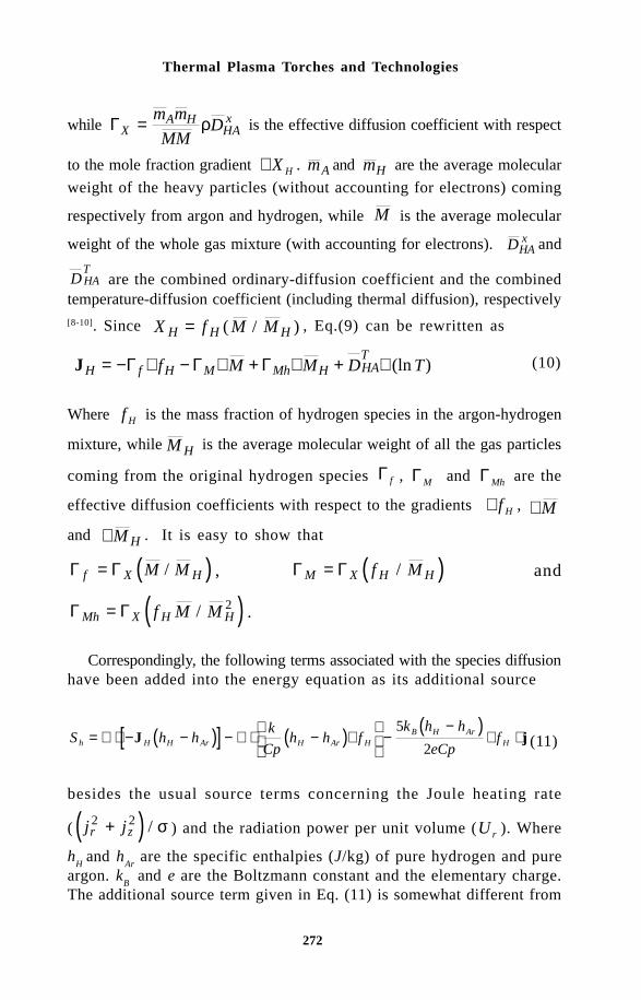
272
Thermal Plasma Torches and Technologies
while ΓXA H
HAxm m
MMD= ρ is the effective diffusion coefficient with respect
to the mole fraction gradient ∇ X H . mA and mH are the average molecular
weight of the heavy particles (without accounting for electrons) coming
respectively from argon and hydrogen, while M is the average molecular
weight of the whole gas mixture (with accounting for electrons). DHAx and
D HAT
are the combined ordinary-diffusion coefficient and the combinedtemperature-diffusion coefficient (including thermal diffusion), respectively[8-10]. Since X f M MH H H= ( / ) , Eq.(9) can be rewritten as
JH f H M Mh H HAT
f M M D T= − ∇ − ∇ + ∇ + ∇Γ Γ Γ (ln ) (10)
Where f H is the mass fraction of hydrogen species in the argon-hydrogen
mixture, while M H is the average molecular weight of all the gas particles
coming from the original hydrogen species Γ f , ΓM and ΓMh are the
effective diffusion coefficients with respect to the gradients ∇ f H , ∇ M
and ∇ M H . It is easy to show that
( )Γ Γf X HM M= / , ( )Γ ΓM X H Hf M= / and
( )Γ ΓMh X H Hf M M= / 2 .
Correspondingly, the following terms associated with the species diffusionhave been added into the energy equation as its additional source
( )[ ] ( ) ( )S h h
k
Cph h f
k h h
eCpfh H H Ar H Ar H
B H ArH= ∇ ⋅ − − − ∇ ⋅ − ∇
−
−∇ ⋅J j
5
2 (11)
besides the usual source terms concerning the Joule heating rate
( ( )j jr z2 2+ / σ ) and the radiation power per unit volume (Ur ). Where
hH
and hAr
are the specific enthalpies (J/kg) of pure hydrogen and pureargon. k
B and e are the Boltzmann constant and the elementary charge.
The additional source term given in Eq. (11) is somewhat different from
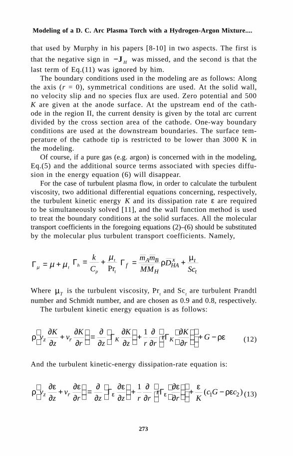
273
Modeling of a D. C. Arc Plasma Torch with a Hydrogen-Argon Mixture....
that used by Murphy in his papers [8-10] in two aspects. The first is
that the negative sign in −J H was missed, and the second is that the
last term of Eq.(11) was ignored by him.The boundary conditions used in the modeling are as follows: Along
the axis (r = 0), symmetrical conditions are used. At the solid wall,no velocity slip and no species flux are used. Zero potential and 500K are given at the anode surface. At the upstream end of the cath-ode in the region II, the current density is given by the total arc currentdivided by the cross section area of the cathode. One-way boundaryconditions are used at the downstream boundaries. The surface tem-perature of the cathode tip is restricted to be lower than 3000 K inthe modeling.
Of course, if a pure gas (e.g. argon) is concerned with in the modeling,Eq.(5) and the additional source terms associated with species diffu-sion in the energy equation (6) will disappear.
For the case of turbulent plasma flow, in order to calculate the turbulentviscosity, two additional differential equations concerning, respectively,the turbulent kinetic energy K and its dissipation rate ε are requiredto be simultaneously solved [11], and the wall function method is usedto treat the boundary conditions at the solid surfaces. All the moleculartransport coefficients in the foregoing equations (2)–(6) should be substitutedby the molecular plus turbulent transport coefficients. Namely,
Γµ µ µ= + tΓh
p
t
t
k
C= + µ
PrΓ f
A B
HHAx t
t
m m
MMD
Sc= +ρ µ
Where µT is the turbulent viscosity, Prt and Sc
t are turbulent Prandtl
number and Schmidt number, and are chosen as 0.9 and 0.8, respectively.The turbulent kinetic energy equation is as follows:
ρ∂∂
∂∂
∂∂
∂∂
∂∂
∂∂
ρεvK
zv
K
r z
K
z r rr
K
rGz r K K+
=
+
+ −Γ Γ
1 (12)
And the turbulent kinetic-energy dissipation-rate equation is:
ρ∂ε∂
∂ε∂
∂∂
∂ε∂
∂∂
∂ε∂
ερεε εv
zv
r z z r rr
r Kc G cz r+
=
+
+ −Γ Γ
11 2( ) (13)

274
Thermal Plasma Torches and Technologies
where
++
−+
+
+
+
=2
22222
222
z
v
r
v
r
v
r
v
z
v
r
v
z
v
r
v
Grz
rzr
t
∂∂
∂∂
∂∂
∂∂
∂∂
∂∂
µ
θθθ
(14)
and
ΓKt
K
= +µ µσ
Γεε
µ µσ
= + t
The turbulent viscosity is determined by µ ρ εµt c K= 2 / . The modelconstants used in this turbulent model, c c c k1 2, , ,µ σ and σε , are chosenas 1.44, 1.92, 0.09, 1.0 and 1.3, respectively.
Special attention has to be paid to the treatment of the near-wallregion adjacent to the electrodes. Because the physical mechanismsin the plasma sheath are very complicated and quite different from thearc-column region, and because so far our understanding about thephenomena inside the sheath is considerably incomplete, we employ arelatively simple but rather powerful approach to calculate the elec-tric conductivity of the near-wall region in our simulation. Since thenon-LTE state is expected to prevail in the near-wall region, we as-sume that the two-temperature plasma model can be employed in theregion between a grid point C at the electrode surface and its neighbor
0 0.01 0.02 0.03 0.04
Axial Distance (m)
-0.004
-0.003
-0.002
-0.001
0
0.001
0.002
0.003
0.004
Rad
ial
Dis
tanc
e(m
)
0 0.01 0.02 0.03 0.04
Axial Distance (m)
-0.004
-0.003
-0.002
-0.001
0
0.001
0.002
0.003
0.004
Rad
ialD
ista
nce
(m)
18 15
12
4
9
17 16 14 13
11
10
11
Fig. 3 The isotherms (×103K) for the case of laminar flow regime.
Fig. 2 The stream lines for the case of laminar flow regime.
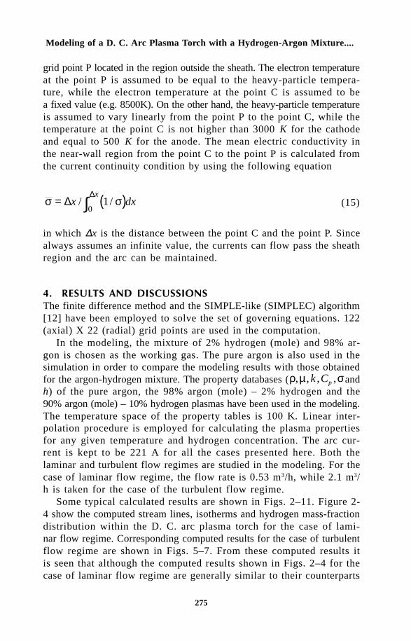
275
Modeling of a D. C. Arc Plasma Torch with a Hydrogen-Argon Mixture....
grid point P located in the region outside the sheath. The electron temperatureat the point P is assumed to be equal to the heavy-particle tempera-ture, while the electron temperature at the point C is assumed to bea fixed value (e.g. 8500K). On the other hand, the heavy-particle temperatureis assumed to vary linearly from the point P to the point C, while thetemperature at the point C is not higher than 3000 K for the cathodeand equal to 500 K for the anode. The mean electric conductivity inthe near-wall region from the point C to the point P is calculated fromthe current continuity condition by using the following equation
( )σ σ= ∫∆∆
x dxx
/ /10
(15)
in which ∆x is the distance between the point C and the point P. Sincealways assumes an infinite value, the currents can flow pass the sheathregion and the arc can be maintained.
/ $*,&(, #",&,,"%#,The finite difference method and the SIMPLE-like (SIMPLEC) algorithm[12] have been employed to solve the set of governing equations. 122(axial) X 22 (radial) grid points are used in the computation.
In the modeling, the mixture of 2% hydrogen (mole) and 98% ar-gon is chosen as the working gas. The pure argon is also used in thesimulation in order to compare the modeling results with those obtainedfor the argon-hydrogen mixture. The property databases (ρ µ σ, , , ,k Cp andh) of the pure argon, the 98% argon (mole) – 2% hydrogen and the90% argon (mole) – 10% hydrogen plasmas have been used in the modeling.The temperature space of the property tables is 100 K. Linear inter-polation procedure is employed for calculating the plasma propertiesfor any given temperature and hydrogen concentration. The arc cur-rent is kept to be 221 A for all the cases presented here. Both thelaminar and turbulent flow regimes are studied in the modeling. For thecase of laminar flow regime, the flow rate is 0.53 m3/h, while 2.1 m3/h is taken for the case of the turbulent flow regime.
Some typical calculated results are shown in Figs. 2–11. Figure 2-4 show the computed stream lines, isotherms and hydrogen mass-fractiondistribution within the D. C. arc plasma torch for the case of lami-nar flow regime. Corresponding computed results for the case of turbulentflow regime are shown in Figs. 5–7. From these computed results itis seen that although the computed results shown in Figs. 2–4 for thecase of laminar flow regime are generally similar to their counterparts

276
Thermal Plasma Torches and Technologies
for the case of turbulent flow regime shown in Figs. 5–7, the detailsof those contours are somewhat different. Due to the heating of thegas in the arc region, the space between the stream lines near the torchaxis is much greater than that near the tube wall. The highest tem-perature appears at the axis and locates at a short distance downstreamfrom the cathode tip. The maximum value of the hydrogen mass fractionis 2–3 times as great as its inlet value, showing an appreciable demixingeffect. In comparison with the case of laminar flow, the stream linesare a little more appreciably shifted towards the wall, the highest temperatureis about 2000 K higher and the location of the arc attachment at theanode surface appears at a more downstream region, while the maximumvalue of hydrogen mass fraction is a little greater for the case of the
0 0.01 0.02 0.03 0.04
Axial Distance (m)
-0.004
-0.003
-0.002
-0.001
0
0.001
0.002
0.003
0.004
Rad
ialD
ista
nce
(m)
2.6
2.21.8
1.4
1.0
0.6
0.2
0.6
1.0
0 0.01 0.02 0.03 0.04
Axial Distance (m)
-0.004
-0.003
-0.002
-0.001
0
0.001
0.002
0.003
0.004
Rad
ialD
ista
nce
(m)
Fig. 4 The mass fraction of hydrogen (×10–3K) for the case of laminar flow regime.Inlet value: 1.02×10⁻³.
Fig. 5 The stream lines for the case of turbulent flow regime.
Fig. 7 The hydrogen mass-fraction () contours for the case of turbulent flow regime.Inlet value: 1.02.
Fig. 6 The isotherms ( K) for the case of turbulent flow regimes.
0 0.01 0.02 0.03 0.04
Axial Distance (m)
-0.004
-0.003
-0.002
-0.001
0
0.001
0.002
0.003
0.004
Rad
ialD
ista
nce
(m)
20 18 16
14
12
104
0 0.01 0.02 0.03 0.04
Axial Distance (m)
-0.004
-0.003
-0.002
-0.001
0
0.001
0.002
0.003
0.004
Rad
ialD
ista
nce
(m)
0.6
1.01.4
1.8
2.22.6
3.0
1.0
0.60.2

277
Modeling of a D. C. Arc Plasma Torch with a Hydrogen-Argon Mixture....
0.01 0.02 0.03 0.04 0.05100
150
200
250
300
350
400
450
Axial Velocity
Axi
al V
elo
city
(m
/s)
Axial Distance (m)
12
13
14
15
16
17
18
19
Tem
pe
ratu
re (10
3 K)
Temperature
0.01 0.02 0.03 0.04 0.05100
150
200
250
300
350
400
450
Axial Velocity
Axi
al V
elo
city
(m
/s)
Axial Distance (m)
12
13
14
15
16
17
18
19
Tem
pe
ratu
re (10
3 K)
Temperature
turbulent flow.Figure 8 and 9 plot the computed variations of the axial velocity and
the gas temperature along the torch axis for the laminar and turbu-lent regimes, respectively. The axial variations of the gas temperatureare quite similar for both the laminar and the turbulent flow regimes,but the maximum temperature is 2000 K higher for the turbulent re-gime. Although the flowrate of the working gas for the turbulent flowregime is about 4 times as great as that for the case of laminar flowregime, the maximum axial velocity at the torch axis for the case ofthe turbulent flow regime is only about 130% greater than that for thecase of laminar flow regime due to a fatter velocity profile for the former.The highest axial velocity for the turbulent flow regime appears at asomewhat more downstream location in comparison with that for thelaminar flow regime. The averaged value of the axial gas velocity atthe torch exit is much greater than that near the torch inlet due to theintense gas heating. Hence the swirl number assumes a very small valueat the torch exit, although its value is rather high at the torch inlet.
Figure 10 compares the radial distributions of the hydrogen massfraction at 5 different axial locations for the case of laminar flow regime.It is seen that significant demixing phenomenon appears within the plasmatorch, showing appreciable non-uniform radial hydrogen concentrationdistributions after the working gas has been heated by the arc. Thehydrogen species is appreciably concentrated towards the high tem-perature region near the torch axis. The maximum value of the hydrogenmass fraction appears at the torch axis and at the location 0.02 mdownstream from the cathode tip.
Figure 11 compares the computed variations of the gas tempera-ture along the torch axis for three different cases: (A) Taking the 2%
Fig. 8 The computed variations of the axial velocity and the temperature along thetorch axis for the case of laminar flow regime.Fig. 9 The computed variations of the axial velocity and the temperature along thetorch axis for the case of turbulent flow regime.

278
Thermal Plasma Torches and Technologies
0.01 0.02 0.03 0.04 0.0512
13
14
15
16
17
18
19
2% Hydrogen With Demixing
2% Hydrogen Without Demixing
100% Argon
Tem
pera
ture
(10
3 K
)
Axial Distance (m)
Fig. 10 The computed hydrogen mass fraction (×10–3) distributions at 5 different axiallocations. Laminar flow regime.Fig. 11 Comparison of the computed temperature distributions along the torch axisfor three different cases. Laminar flow regime.
-0.004 -0.002 0.000 0.002 0.0040.0
0.5
1.0
1.5
2.0
2.5
3.0
Inlet
0.013
0.017
0.035
x=0.02
Mas
s F
ract
ion
( 10
-3 )
Radial Distance (m)
hydrogen – 98% argon as the working gas and taking the demixing effectinto account; (B) Taking the 2% hydrogen – 98% argon as the workinggas but the demixing effect is ignored; and (C) Taking the pure ar-gon as the working gas of the plasma torch. Examination of the computedaxial variations of the gas temperature in Fig. 11 reveals that the demixingeffect appreciably changes the temperature distribution and enhancesthe value of the highest temperature. Since only small fraction ofhydrogen is added into the working gas, the properties of the2% hydrogen – 98% argon mixture is not quite different from thoseof the pure argon. Hence, the computed temperature distribution forthe case (B) is almost identical to that for the case (C). However, ifthe demixing effect is included, the energy transport and thus the temperaturedistribution are appreciably affected.
In the present modeling, an important error source is that the plasmaflow has been assumed to be axisymmetrical, and thus all the work-ing gas will be heated effectively by the arc. A three-dimensional effectalways exists in an actual plasma torch, and a part of the working gasmay flow in a roundabout way without passing the arc region. Theapplicability of the two-equation turbulence model to the plasma torchis questionable. The non-LTE effect may be important, especially inthe region near the torch wall. More sophisticated study is highly desiredto clarify the effects due to these complicated factors.
0#%(* *#This work was supported by the National Natural Science Foundation of China (No.59676011) and the Doctorate Thesis Fund of the National Education Department of

279
Modeling of a D. C. Arc Plasma Torch with a Hydrogen-Argon Mixture....
China. The authors would like to thank Dr. A. B. Murphy whose property databasefor the argon-hydrogen mixture has been used in this study.
$*1*$*#*,1 A. H. Dilawari, etal, ISIJ International, 30, No.5, 381-389 (1990).2 D. A. Scott, et al, Journal of Applied Physics, 66, No.11, 5232-5239
(1989).3 R. Westhoff and J. Szekely, Journal of Applied Physics, 1991, 70 (7),
3455-3466.4 C. George and E. Pfender, In: Numerical Simulation of a Multi-Com-
ponent Non-Transferred Constricted DC Arc, Proceedings of the 13thInternational Symposium on Plasma Chemistry, Vol.1, Beijing UniversityPress, Beijing (1997), pp.314-319.
5 M. Suzuki, et al, Plasma Chemistry and Plasma Processing, 16, No.4,399-415 (1996).
6 J. O. Hirschfelder, et al, Molecular Theory of gases and Liquids, Chapter8, John Wiley & Sons Inc., New York (1954).
7 S. Chapman and T. G. Cowling, The Mathematical Theory of Non-UniformGases, Chapter 14, 3rd Edition, Cambridge University Press, Cam-bridge (1990).
8 A. B. Murphy and C. J. Arundell, Plasma Chemistry and Plasma Process-ing, 14, No.4, 451-591 (1994).
9 S. C. Snyder, et al, Physical Review E, 52, No.3, 2999-3009 (1995).1 0 A. B. Murphy, Journal of Physics D: Applied Physics, 29, No.3, 1922-
1932 (1996).11 B. E. Launder and D. B. Spalding, Computer Methods in Applied Mechanics
and Engineering, 3, 269-289 (1974).1 2 S.V. Patankar, Numerical Heat Transfer and Fluid Flow, Hemisphere,
Washington, D.C, (1980).
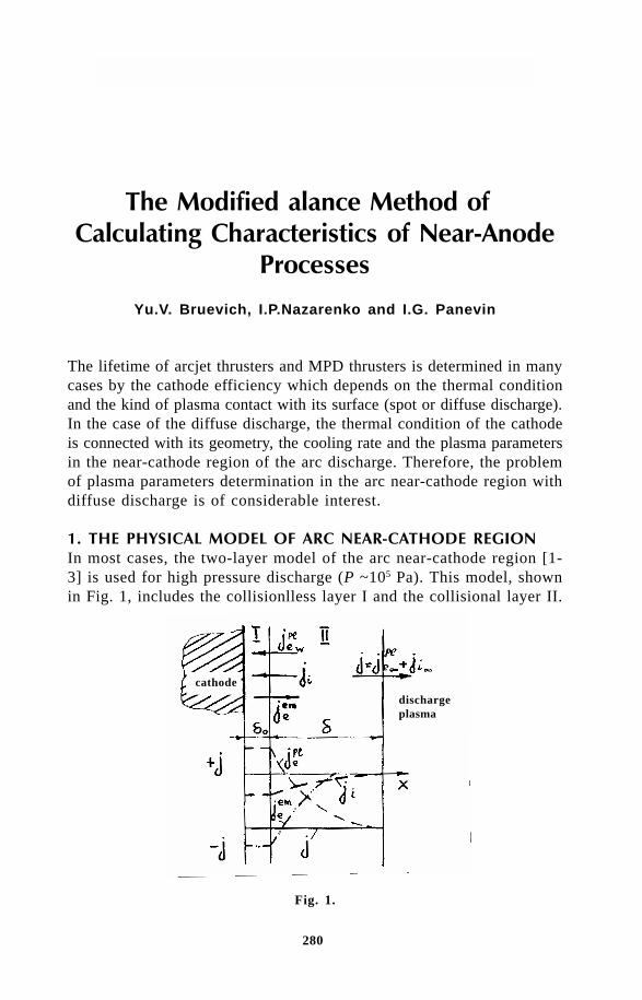
280
Thermal Plasma Torches and Technologies
Yu.V. Bruevich, I.P.Nazarenko and I.G. Panevin
The lifetime of arcjet thrusters and MPD thrusters is determined in manycases by the cathode efficiency which depends on the thermal conditionand the kind of plasma contact with its surface (spot or diffuse discharge).In the case of the diffuse discharge, the thermal condition of the cathodeis connected with its geometry, the cooling rate and the plasma parametersin the near-cathode region of the arc discharge. Therefore, the problemof plasma parameters determination in the arc near-cathode region withdiffuse discharge is of considerable interest.
!" !#$$!"$%!In most cases, the two-layer model of the arc near-cathode region [1-3] is used for high pressure discharge (P ~105 Pa). This model, shownin Fig. 1, includes the collisionlless layer I and the collisional layer II.
Fig. 1.
dischargeplasma
cathode
281
Modified Balance Method of Calculating Characteristics...
The collisionless layer (the space charge layer) contacts with the cathodesurface. Usually it is assumed that its thickness d
0 is less than the electron
free path length and there are no interactions between plasma and particleswithin the layer I. Moreover, it is considered that in the layer I the positivevolume charge is concentrated in the main and a large part of the cathodepotential drop U
c is realized. The electrical field which exists in the layer
I accelerates the emission electrons moving from the cathode surfacetowards the discharge plasma, and also the plasma ions moving to thecathode surface. But the electric field in this layer brakes the plasmaelectrons which direct to the cathode surface, and only the fast electronswhose energy is enough to get over the braking barrier U
c are able to
reach the cathode surface. The total current density j=jeem+j
i+j
epl and
its components (the plasma ion current density ji, the plasma electron
current density jepl and the emission electron current density j
eem) are
invariable within the collisionless layer. The emission electrons whichare accelerated in the layer I have on the boundary between the layersI and II the energy (eU
c+5/
2kT
w). Here T
w - the cathode surface temperature,
e - the electron charge, k - the Boltzmann’s constant. As for the arcdischarge in the arcjet eU
c>>kT
w, it is possible to consider the emission
electrons as a monoenergetic stream with energy eUc. This stream brings
in the collisional layer the impulse stream and the energy flux, wheren
eem and V
eem - the emission electron density and their velocity on the
boundary between the layers I and II, me - electron mass. These impulse
stream and energy flux pass to the plasma particles in the layer II.The collisional (ionization) layer thickness δ is much bigger than the
free path length of the plasma particles. Within the layer II the ion currentforms, the emission electron stream relaxes and the heavy particlestemperature changes from the temperature T
w on the boundary with the
layer I to the temperature close to the electron temperature at the boundarywith discharge plasma T
e∞. Because of the difference between the heavyparticles and electron temperatures and also because of the ionizationequilibrium displacement, the plasma composition in the layer II dif-fers from the equilibrium composition.
The total current density j is also invariable within the collisionallayer. However, as it is followed from Fig. 1, the current densities j
eem
and ji within the layer II change their values, and the current density
jepl changes the value and the sign: at the boundary with the layer I the
current density jepl is provided with the fast plasma electrons and is directed
to the cathode surface, on the boundary with discharge plasma the currentdensity j
epl is caused by the motion of all plasma electrons and is di-
rected to the discharge plasma.The energy losses with the streams of the plasma particles which leave

282
Thermal Plasma Torches and Technologies
the layer II through the boundaries are compensated for by the energysupply with the stream of emission electrons.
There two main calculation methods for determination of the near-cathode region characteristics. The first method, which we shall namethe exact method, is based on the differential equation system solutionand allows us obtain information about the cathode potential drop U
c,
the heat flux q0 which passes from the near-cathode plasma to the cathode
surface and also the information on the distribution over the collisionallayer thickness of temperature and the concentrations of the particles,the electric field strength E, plasma potential difference j, and so on.
The second method which is used for the estimation of Uc and q
0
values proceeds from the integral balance correlations.
& ' ( !!"As the collisional layer thickness δ in the diffuse discharge is much smallerthan the radial dimension of the discharge, the equation system for thelayer II is written in the one-dimensional approach. Besides, it is suggestedthat the emission electron current density may be written with the helpof Richardson–Dashman’s equation with Schottky’s correction.
The equation system which takes into account the processes of re-laxation of emission electrons, the formaton of the ion current and theionization equilibrium displacement and so on, was suggested in [3]:
+ =
+ ⋅ − +
−
− − +
λ χ
ε
(1)
5
2k n U V n U V
dT
dx
d
dx
dT
dxW j Ea a i i e e i+ + + =
+ + λ (2)
Wm
Mkn v v T Te
e
ie ea ei e= +3 – (3)
– – – – – –en EdP
dx
m n V
k kV V
m n V
k kV Ve
e c e ea
add eae a
e e ei
add eae iσ σ σ σ = 0 (4)
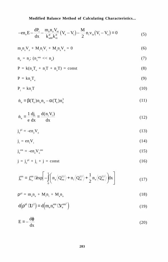
283
Modified Balance Method of Calculating Characteristics...
– – – – – –en EdP
dx
m n V
k kV V
Mn v V Ve
i e e ei
add eie i i ia i aσ σ
20= (5)
men
eV
e + M
in
iV
i + M
an
aV
a = 0 (6)
ne = n
i; (n
eem << n
e) (7)
P = k(neT
e + n
iT + n
aT) = const (8)
P = kneT
e (9)
Pi = kn
iT (10)
( ) – ( )n T n n T ne e e a e e= β α 3 (11)
( )
ne
dj
dx
d n V
dxei i i= =1
(12)
jepl = -en
eV
e (13)
ji = en
iV
i (14)
jeem = -en
eV
eem (15)
j = jepl + j
i + j = const (16)
j j n Q n Q n Q dxeem
eem
a ea i ei e ea
x
w= ⋅ + +
exp – . . .1 1 1 1 1 1
0
1
2 (17)
ρpl = men
e + M
in
i + M
an
a (18)
d U d m n Vple e
emeemρ ⋅ = ⋅2 2 (19)
Ed
dx= –
ϕ (20)
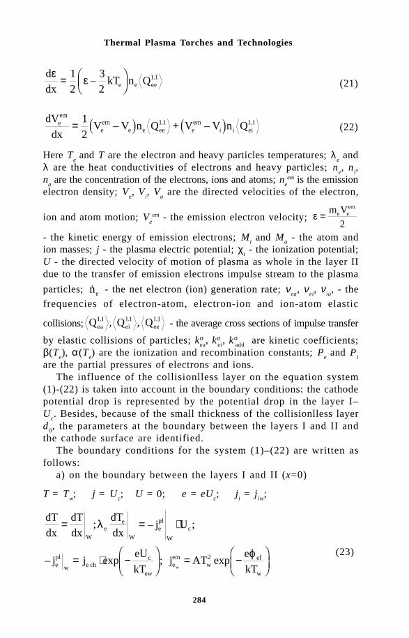
284
Thermal Plasma Torches and Technologies
d
dxkT n Qe e ee
ε ε=
1
2
3
21 1– .
(21)
dV
dxV V n Q V V n Qe
em
eem
e e ee eem
i i ei= +1
21 1 1 1– –. . (22)
Here Te and T are the electron and heavy particles temperatures; λ
e and
λ are the heat conductivities of electrons and heavy particles; ne, n
i,
na are the concentration of the electrons, ions and atoms; n
eem is the emission
electron density; Ve, V
i, V
a are the directed velocities of the electron,
ion and atom motion; Veem - the emission electron velocity; ε = m Ve e
em
2- the kinetic energy of emission electrons; M
i and M
a - the atom and
ion masses; j - the plasma electric potential; χi - the ionization potential;
U - the directed velocity of motion of plasma as whole in the layer IIdue to the transfer of emission electrons impulse stream to the plasma
particles; ne - the net electron (ion) generation rate; νea
, νei, ν
ia, - the
frequencies of electron-atom, electron-ion and ion-atom elastic
collisions; Q Q Qea ei ee1 1 11 1 1. . ., , - the average cross sections of impulse transfer
by elastic collisions of particles; kσea
, kσei, kσ
add are kinetic coefficients;
β(Te), α(T
e) are the ionization and recombination constants; P
e and P
i
are the partial pressures of electrons and ions.The influence of the collisionlless layer on the equation system
(1)-(22) is taken into account in the boundary conditions: the cathodepotential drop is represented by the potential drop in the layer I–U
c. Besides, because of the small thickness of the collisionlless layer
d0, the parameters at the boundary between the layers I and II and
the cathode surface are identified.The boundary conditions for the system (1)–(22) are written as
follows:a) on the boundary between the layers I and II (x=0)
T = Tw; j = U
c; U = 0; e = eU
c; j
i = j
iw;
dT
dx
dT
dx
dT
dxj U
j jeU
kTj AT
e
kT
We
e
Wepl
W
c
epl
w e chc
eweem
wef
ww
= = ⋅
= ⋅ −
= −
; – ;
– exp ; exp
λ
ϕ2 (23)

285
Modified Balance Method of Calculating Characteristics...
b) on the boundary with the discharge plasma (x = d)
jeem = 0;
dT
dx
dT
dxC
dn
dxCe e
∞ ∞ ∞
= = =1 2; ; (24)
Here A - Richardson’s constant, ϕef - the effective material work function,
indices “w” and “∞” - mean the conditions on the boundary betweenlayers I and II and on the boundary with the discharge plasma, accordingly.
The value of the heat flux q0 which is passed into the cathode body
is determined from the energy balance on the cathode surface
jkT
ej U
dT
dx
q T jkT
e
epl
W
ewef iw c i ef
w w eem ew
efw
⋅ +
+ + − + =
= + + +
5
2
5
204
ϕ χ ϕ λ
ε σ ϕ
(25)
where ew - the blackness degree of the cathode surface, s - the Stephan-
Boltzmann’s constant.As shown in [3], the solution of the equation system (1)–(22) is a
relatively labour-consuming procedure and requires the large expenditureof the calculation time. Therefore, the set of the received solutions islimited: we calculated the near-anode processes characteristics for thearc discharge burning in argon (P = 105 Pa) on the tungsten cathodefor the different values of T
ew when the values of T
w or q
0 remain in-
variable.
) ( !!"The balance calculation method which is used usually is approximateand does no take into account some of the processes taking place inthe collisional layer. In this method, it is assumed that the electron andheavy particles temperatures are constant in the layer II. Besides, it issuggested that the energy flux j
eem·U
c carried in the layer II by the emission
electrons is spent on the compensation for energy losses with the ion
current jkT
eiw iwχ +
5
2 , with the fast plasma electrons current and with
total current on the boundary with the discharge plasma jkT
ee⋅ 5
2.

286
Thermal Plasma Torches and Technologies
The equation system in the balance method which is used usuallylooks as follows [4]:
j = jeem + j
i + j
ewpl (26)
= ⋅ −
ϕ (27)
ϕef = ϕ
w - Dj (28)
∆ϕ = ⋅ −
(29)
( ) =
(30)
= ⋅ −
= −
(31)
= =
(32)
P = k(neT
e + n
iT
i + n
aT
a) (33)
ne = n
i (34)
b(Te)n
en
a = a(T
e)n
e3 (35)
where Ai - the atom weight,
=
π,
=
π , ϕw - the cath-
ode material work function.The energy balance equations on the cathode surface and for the collisional
layer as a whole are solved in common with the equations (26)–(35)
q T jkT
e
j U jkT
e
w w eem w
ef
i c ef epl e
04
1
5
2
5
2
+ + +
=
= + +
ε σ ϕ
χ ϕ– (36)

287
Modified Balance Method of Calculating Characteristics...
j UkT
ej
kT
e
j UkT
ej
kT
e
eem
cw
i i
epl
ce e
+
= +
+
+
+ ⋅
5
2
5
2
5
2
5
2
χ
(37)
The equation system (26)–(37) was solved for such conditions as thesystem (1)–(22). The comparison of the calculation results which wasobtained by the exact and balance methods in [3] showed that the cathodepotential drop values U
c calculated with the help of the balance method
exceed by 1–2 V the values of the cathode potential drop which weredetermined with the exact method. The difference of the values of theheat flux q
0 which is passed into the cathode body is more essential.
The values q0 which were determined by the balance method can be twice
as high as the values q0 calculated by the exact method.
Since the balance method is essentially less labour-consuming thanthe exact method, it is expedient to modify this method which wouldmake it possible to develop a relatively simple procedure and increasethe accuracy of determination of the values U
c and q
0.
* !"#" !"The considerable difference in the values of q
0 calculated by the different
methods are associated with the fact that the conventional balance metjoddoes not take into account some special features of the collision layerappearing when calculating its characteristics by the exact calculationmethod. For an arc discharge burning in argon (P ~ 105 Pa) on a tungstencathode, these peculiarities may be written as follows:
1. the electron temperature near the cathode surface Tew
exceeds theelectron temperature at the discharge plasma boundary T
e∞ by ~2000K;
2. the heavy particle temperature T near the cathode surface is equalto the cathode surface temperature T
w and at the discharge plasma boundary
T ≈ Te∞;
3. the heat flux λ
determined by the heavy particle heat con-
ductivity changes only slightly and is approximately equal to 4×10³ W/cm2;
4. the current density on the cathode surface jiw
is determined by thediffusion in the near-cathode layer and may be written as j
iw = B(T
e)·j
ich

288
Thermal Plasma Torches and Technologies
where B(Te) is the coefficient which depends on temperature T
ew; here
jich
is the chaotic ion current density;5. the near-cathode plasma composition is non-equilibrium, the maximum
possible electron generation rate values at the temperatures Tew
and Te∞
make up about 0.95 from the value
which is the maximum valueat the corresponding temperatures T and T
e;
6. under the effect of the emission electrons, the plasma motion asa whole in the collisional layer is directed towards the discharge plasmaand through the boundary with the discharge plasma the energy fluxU·5/
2kT
e∞ (ne∞ + ni∞ + n
a∞) goes out.Taking these peculiarities into account, the equation system for the
modified balance method has the following form:
j = jeem + j
iw + j
ewpl (38)
= ⋅ −
ϕ (39)
jef = j
w - Dj (40)
∆ϕ = ⋅ −
(41)
( ) =
(42)
= ⋅ −
= −
(43)
= = ⋅
(44)
P = k(neT
e + n
iT
i + n
aT
a)
w = k(n
eT
e + n
iT
i + n
aT
a)∞ (45)
T∞ = Te∞ (46)
ne = n
i (47)
Te∞ = T
ew– 2000 (48)
= −β α (49)

289
Modified Balance Method of Calculating Characteristics...
= ⋅ (50)
( )
= ⋅+ +∞ ∞ ∞
(51)
The energy balance equations in the modified balance method maybe written as follows:
+ + +
= +
+ + − +
+ +
ε σ ϕ λ
χ ϕ ϕ (52)
j UkT
e
dT
dxj U
kT
ej
kT
e
jkT
ej U kT n n n
eem
cw
epl
cew
iw iw
eepl
c e i a
w+
= + +
+ +
+
+ ⋅ + + ⋅ + +∞∞ ∞ ∞ ∞
5
2
5
2
5
2
5
2
5
2
λ χ
(53)
The results of calculations using the equation system (38)–(53) forthe arc discharge burning in argon (P = 105 Pa) on the tungsten cath-ode are presented in Fig. 2 and 3.
The modified balance method, characterised by a considerably lowerlabour content in comparison with the exact method, was uased to calculatethe range of change of cathode surface temperature T
w from 3500 to
4000 K, the near-cathode electron temperature Tew
from 15000 to 23000K. Figure 2 and 3 shows the dependences of the cathode potential dropU
c and the heat flux q
0 on the total current density j.
The graphs show the influence on the values Uc and q
0 of param-
eters such as the temperature Tw and T
ew. Figure 2 and 3 also compare
the values Uc and q
0 calculated by the exact method. The sufficient
correspondence of the results obtained by the exact and modified bal-ance methods allows us to apply the modified balance method for calculatingthe near-cathode region characteristics in argon.
The application of the modified balance method for other ranges ofP, T, T
e in argon or the arc discharge burning in other gases requires
additional calculations by the exact method.

290
Thermal Plasma Torches and Technologies
Fig.1
Fig.2
References1. T.H. Lee, A.N.Greenwood and W.D.Breingan, A self consistent model
for the cathode region of a high pressure arc, Proc. 7th Intern. Conf.Phenomena Ionized Gases. Belgrade, 1965, p.670-680.
2. K.C.Hsu and E.Pfender, Analysis of the cathode region on a free-burninghigh intensity argon arc, J.Appl.Phys., vol.54,N7, 1983,p.1769-1777.
3. A.M.Zimin, I.P.Nazarenko, I.G.Panevin, V.I.Khvesyuk. Mathematical modelingof cathode processes. Nauka, Novosibirsk (1993).
4. Near-electrode processes and erosion of plasmatron electrodes / M.F.Zhukov(editor) Nauka, Novosibirsk (1997).

291
Application of Heat Diffusion Theory to Cold Electrode Erosion
A. Marotta and L. I. Sharakhovsky1
Instituto de Física “Gleb Wataghin”, Universidade Estadual de Campinas,Unicamp 13083-970, Campinas, São Paulo, Brazil
The problem of erosion is most actual for electric arc heater (EAHs)electrodes, especially the cathode, because of its higher erosion thanthe anode. Operating in the regime of autothermoionic emission,characterized by extremely high current densities and heat fluxes,these electrodes can be used only under the condition of rapiddisplacement of the arc spot. To avoid fast destruction of the electrode,a magnetic field or a gas vortex is usually used.
Extensive efforts have been made by many authors to understand thephysics underlining the erosion of copper electrodes (see [1] and ref-erences therein). In order to establish the dominant mechanism of erosionin oxidized cathode surfaces, Guile et al [2] investigated different physical,chemical, and electrochemical processes, using an Arrhenius-type equationof the form [2]
d dm A G kNTe/ exp( / ),τ = −∆ (1)
where dm/dτ is the mass erosion rate, A is the “rate factor”, ∆Ge is the
effective erosion activation energy, k is the Boltzmann’s constant, N isthe Avogadro’s number and T is the electrode surface temperature. Thevalue of ∆G
e was found by Guile to be close to the activation energy
for the interatomic bond ‘loosening’ (fusion) of the pure metal copperelectrode material, rather than to the activation energy of other processes,such as oxide or metal vaporization, oxide decomposition, etc. The Guile
1 Permanent address: The Luikov Heat & Mass Transfer Institute, P. Brovkistreet, 15, 220072, Minsk, Republic of Belarus

292
Thermal Plasma Torches and Technologies
conclusion was that the fusion of the solid electrode metal plays thedominant role in the erosion of oxidized copper cathodes.
Recently, a thermophysical macroscopic model for cold cathode erosionhas been presented in [1,3–5]. The model is based on the cathode fu-sion mechanism proposed by Guile. The erosion model gives the spe-cific mass erosion rate g (kg C–1) as function of the operating parameters,such as the current I, the arc displacement velocity v and the electrodesurface temperature T. Besides these, there are parameters character-istic for the erosion process, the minimal erosion value (accounting forthe “microerosion” process) g
0, and the effective erosion enthalpy h
ef.
The parameter hef accounts for all processes ending up in electrode erosion.
A parameter similar to hef is also found in the technology of heat shielding
materials for space systems moving in the atmosphere with hypersonicspeed. There, the effective enthalpy is obtained as the ratio of the heatflux, which enters the body, to the mass flow rate of the ablated material.The effective enthalpy is a convenient approach to deal with the complexconditions of unsteady and combined (thermal, electromagnetic,hydrodynamic, etc.) effects that occur in cold electrode erosion phenomena.The kinetics of these processes is very complex, and their precise calculationis hardly feasible. Here, we will obtain the effective enthalpy of erosionsemi-empirically: the value of the erosion will be measured experimentally,and the heat of erosion will be calculated theoretically in accordancewith the present thermophysical model [1].
New characteristic arc spot parameters, the volt equivalent of thecathode arc spot heat flux U and the effective arc spot current densityj, have been introduced in the thermophysical theory in the place of theusual, the near cathode voltage drop ∆U and the arc spot current densityj, respectively. Electrical and optical methods are often employed to measure∆U and j, for fixed cathode arc spot attachments [6]. In a cold cath-ode, the arc spot has a complex unstable structure, consisting of anagglomeration of many fast moving microspots, as demonstrated byRakhovsky [6]. For these conditions, the measurement of ∆U, and es-pecially of j, by the above mentioned methods, presents serious diffi-culties. This explains the extremely high scattering of experimental dataon cold cathode arc spot current densities, obtained by many authors(up to 5 orders of magnitude, see e.g., [6]).
In the thermophysical approach, U and j are measured by thermalmethods. This permits to obtain, in a straightforward manner, the valueof the arc spot heat flux density q
0= jU to the cathode surface, as U
is thermally measured in such a way that all the near cathode processescontributing to the heating of the cathode spot are included [3]. Ob-viously, this procedure, at the same time excludes all heat fluxes originating
293
Application of Heat Diffusion Theory to Cold Electrode Erosion
at other places than at the near cathode arc spot region. Here, we willalso obtain the effective arc spot current density j semi-empirically, usingerosion experimental data and the thermophysical model of erosion.
The thermophysical model, presented in [1], is based on the assumptionof constant velocity v of the arc spot. However, according to investi-gations of Szente et al [7-9], the chemistry of the surface layer on theelectrode can greatly influence the character of motion of the arc spot.On clean surfaces, in the medium of inert gases, it is characteristic thepresence of a ‘surface’ drag, that leads to a reduction in the velocityand periodic stops of the arc spot, making the arc spot to show a step-wise motion. Molecular gases, such as air and nitrogen, on the otherhand, makes the arc appear to move in a manner more similar to thecontinuous motion.
Below, in the two first sections, we present the thermophysical theoreticalmodel for the continuous and step-wise motions of the arc spot. Next,briefly, we discuss the thermal methods for the measurements of U andj. Then, we present the experimental data for the erosion and comparethem with theoretical results. These last data were taken from experi-ments that models the behavior of the arc in EAHs, as well from ex-periments in Electrical Discharge Machining (EDM) equipments.
We will show that the present thermophysical model gives seriousjustification to the formulation of the problem of erosion in the formof heat diffusion equations, with special initial and boundary conditions,which consider only the integral energy characteristics of the arc spot,the thermophysical properties and the regime of the electrode surface.This approach strongly simplifies the problem of electrode erosion, makingit possible to avoid the formulation of complex and uncertain plasmamicroscopic models.
!"We assume that the Joule heating of the copper cathode under the arcspot can be neglected. This is possible if the arc spot current densitydoes not exceed 108 A/cm2 [10]. Then, the arc spot can be replaced byan ideal circular heat source, with uniformly distributed heat flux densityq
0 = jU = const [10]. We study the heating of the electrode surface in
coordinates attached to and moving with the source with constant velocityv (see Fig. 1). The maximum time of a given electrode point heat exposureto the arc spot is equal to τ
max = d/v, where d is the arc spot diameter.
Due to high arc velocities, the Fourier number Fod
= aτmax
/d2 <<1 [10],where a is the electrode thermal diffusivity. This means higher gradientsof electrode temperature along direction z, perpendicular to the electrodesurface, than along coordinates x and y.

294
Thermal Plasma Torches and Technologies
Then, for the solution of the three-dimensional heat conduction problemwe disregard the heat flow along the surface of the electrode and solvethe one-dimensional heat conduction problem in z, obtaining the solu-tion for the temperature T(z, τ) (see [1]). Here, the time τ is taken withthe meaning of the interval of time since the front edge of the arc spot(line SRT in Fig. 1.) has passed over the point, i.e. τ = l/v (see Fig.1). During time τ a given point on the electrode surface within the arcspot is being heated by the arc. We can distinguish here three possi-bilities: (a) there will be no points under the arc spot reaching the fusiontemperature T
f ; (b) after a certain time τ
0, two zones inside the arc
spot will be found, the zone MRNPM, with temperature T < Tf, and
Fig. 1. Schematic diagram of the arc spot heat source. MRNPM - zone with temperatureT<T
f; MPNQM is the zone with temperature T=T
f (the fusion zone).
the fusion zone MPNQM, with T = Tf =const; and (c) the intermedi-
ate (or transition) case between (a) and (b). It is possible to show thatthe time for a given point under the arc spot to reach the fusion tem-perature T
0 is given by the expression [1]
,)(
4
2
00
−=
q
TT
af λπτ (2)

295
Application of Heat Diffusion Theory to Cold Electrode Erosion
where T and λ are, respectively, the initial temperature and the heatconductivity of the electrode.
In order to characterize the fusion zone extent in the arc spot weuse the non-dimensional parameter f = l
0/d = t
0v/d (see Fig. 1, with points
in the border line MPN at l0 = vτ
0 being the first points to reach temperature
Tf. It is easy to see that f can be written in the following form [1]:
,8
)(25.1
225.1
Uaj
TTsf f −
=λπ
(3)
where Ivs /= we call the normalized velocity. It is obvious that thethree possible domains of values of f, f > 1, f <1 and f = 1 are related,respectively, to the three cases (a), (b) and (c) mentioned above.
It is obvious to assume that, for points in the zone MRNPM, theheat removal Q
r, through heat conduction into the electrode body, will
be equal to the arc spot heat input Q0. However, for the fusion zone,
we assume that the heat removal and heat input over this zone are relatedas Q
r < Q
0, which difference, Q
er=Q
0 – Q
r, is called the erosion heat.
Qer
is the total heat spent in the erosion process, i.e., the heat spentin transforming the electrode mass in the fusion zone from the solid stateinto the plasma one. Further, we assume that the mass erosion rate G(kgs–1) is proportional to the ‘erosion heat’ Q
er, which yields
,0 gIhGhQQQ efefrer ==−= (4)
where hef is the erosion effective enthalpy and g is the specific erosion
rate (kg C–1). Our aim is to calculate the integrals Q0 and Q
r throughout
the entire area of the fusion zone FMPNQM
. Neglecting the thickness ofthe liquid layer, and assuming T = T
f at z = 0, the heat conduction problem
for the fusion zone can then be solved for τ >τ0. The solution of this
problem gives the instantaneous heat flux density, which is removed throughthe fusion zone [1,11]:
.tan2
0
010
τττ
π −= −q
qr (5)
After calculating the integrals Q0 and Q
r over the fusion zone area,
we obtain [1]:
296
Thermal Plasma Torches and Technologies
IUUWIQ erer == (6)
where the non-dimensional function W of the parameter f is given by[1]
,)(4
sin2
211
+−+= − wwffW β
πββ
π (7)
where β, w1 and w
2 are functions of f, shown in [1]. Function U
er=UW
we call the volt-equivalent of erosion heat. Equation (7) can be approximatedby a rather simple expression [1]
.477.104.0
442.0
475.2
13.71
−
++
+−=′≈
fffWW (8)
The standard deviation of (8), with respect to (7), is equal to 0.011 (Wmax
=1).The domains of W and f are related as follows: W= 0 for f ≥ 1 and0 < W < 1 for f < 1. From (6), we obtain the expression for the specificerosion rate [1],
,0efh
UWgg += (9)
where the additional term g0 (called microerosion) has been introduced
to take account of the experimental fact that, even for the case ofW = 0, there is observed a certain minimum value of erosion g =g
0 ~ const. Even when melting and erosion must vanish according to
the above obtained thermophysical result, there remains a certain minimumvalue of erosion because of the deviation of the characteristics of thereal arc spot from the simple model assumed here of an uniform andconstant heat flux density throughout the entire area of the spot.
From the above results, we see that the thermophysical model forcontinuous arc motion can be represented, in the simplest form, by thesystem of three equations (3), (7) or (8) and (9).

297
Application of Heat Diffusion Theory to Cold Electrode Erosion
# $%& !"The step-wise displacement of the arc spot implies the existence of thespot only at certain discrete positions. We assume an infinitely shorttime of displacement of the arc spot from one point to another. Thus,the spot residence time at a given point on the electrode surface canbe written as
τ ν= L / , (10)
where L = nd is the arc spot step length, v is the mean arc spot motionvelocity from spot to spot and n > 1. We assume that the process ofelectrode surface heating within the arc spot during time t takes placeuniformly and simultaneously over the entire arc spot area. After a certaintime t
0 from the beginning of the heating process all the spot area should
reach the temperature of fusion of the electrode Tf.
Up to time τ0
the heat flux supplied to the electrode surface Q0 is
equal to the heat removal Qr through heat conduction into the electrode
body. Starting at time τ0 some heat should be spent in melting the electrode
surface. We call the time-average (over the period of time τ total “erosionheat” flux (in W) Q
er= Q
0 – Q
r, where Q
0 = q
0F is the total average arc
spot heat input during time τ, Qr= Qτ0
+Q is the total average heat removalby heat conduction into the electrode body and F is the area of the spot.Here, Qτ0
= q0Fτ
0/τ is the arc spot average heat input (and heat removal)
during time τ0 and Q (F / ) q dr
0
= τ ττ
τ is the total average heat removal
during time τ > τ0. Calculating this integral using equation (5), we obtain
the total mean erosion heat flux during time τ
Qer
=Q0
– Qr=IUW
s, (11)
where Ws is given by the non-dimensional function
−−
−= − )1(
1tan
2 1ss
s
ss ff
f
fW
π (12)
and fs =τ
0 /τ is the characteristic parameter for the pulsed (or step-wise)
arc spot erosion model. Comparing fs with f in (3), it is possible to show
that these parameters are related by the relationship
.n
ff s = (13)

298
Thermal Plasma Torches and Technologies
Thus, the parameter fs for the step-wise motion of the arc spot is similar
to the parameter f for the continuous arc spot motion model. On theother hand, function W, for the step-wise model is similar to functionW for the continuous model.
Similar to the previous section, using equation (11), and assumingthat the total average erosion heat Q
er is proportional to the mass erosion
rate G (see equation (4)), we obtain the equation for the specific masserosion rate for the step-wise erosion model as
,0ef
s
h
UWgg += (14)
where g0 was introduced for the same reason as in formula (9).
'!$(& !"Firstly, it is useful to compare both, the continuous and step-wise models,called as thermophysical models, with the old Guile model, expressedin the form of the Arrhenius equation (1). In Fig. 2a,b we show thetheoretically calculated curves of erosion g for these two models versusthe inverse value of the electrode temperature. Figure 2a relates to thecontinuous model and 2b to the step-wise one. Therein, we plotted alsothe curves, marked with A, calculated according to (1). In this equationwe used ∆G
e = 0.13 eV in accordance with [2]. The value of A in (1)
was not given by the authors and we have chosen it so as to bring in
Fig. 2. Specific erosion g vs 1/T: (a) continuous model for different values of s(shown); (b) step-wise model for different values of n (shown) and for s =1.5; A -eq. (1), C - continuous model, for s = 1.5.
1 2 3
1
10
(a)
s=0.25
A
s=1.5
s=1.0
s=0.5
g (
10-8 k
g/C
)
1/T (10-3 K-1)
1 2 3
1
10
(b) A
C
n=8
n=4
n=2
n=1
g (
10-8 k
g/C
)
1/T (10-3 K-1)
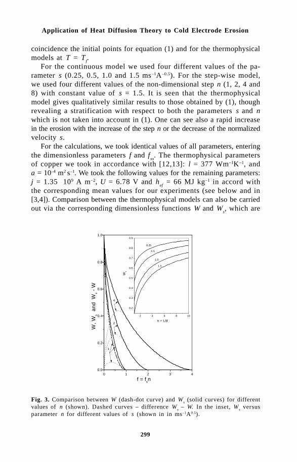
299
Application of Heat Diffusion Theory to Cold Electrode Erosion
coincidence the initial points for equation (1) and for the thermophysicalmodels at T = T
f.
For the continuous model we used four different values of the pa-rameter s (0.25, 0.5, 1.0 and 1.5 ms–1A–0.5). For the step-wise model,we used four different values of the non-dimensional step n (1, 2, 4 and8) with constant value of s = 1.5. It is seen that the thermophysicalmodel gives qualitatively similar results to those obtained by (1), thoughrevealing a stratification with respect to both the parameters s and nwhich is not taken into account in (1). One can see also a rapid increasein the erosion with the increase of the step n or the decrease of the normalizedvelocity s.
For the calculations, we took identical values of all parameters, enteringthe dimensionless parameters f and f
ss. The thermophysical parameters
of copper we took in accordance with [12,13]: l = 377 Wm–1K–1, anda = 10–4 m2 s–1. We took the following values for the remaining parameters:j = 1.35 109 A m–2, U = 6.78 V and h
ef = 66 MJ kg–1 in accord with
the corresponding mean values for our experiments (see below and in[3,4]). Comparison between the thermophysical models can also be carriedout via the corresponding dimensionless functions W and W
s, which are
Fig. 3. Comparison between W (dash-dot curve) and Ws (solid curves) for different
values of n (shown). Dashed curves – difference Ws – W. In the inset, W
s versus
parameter n for different values of s (shown in in ms–1A0.5).
0 1 2 3 40.0
0.2
0.4
0.6
0.8
1.0
4
2
1
W, W
s a
nd W
s - W
f = fsn
2 4 6 8 10
0.2
0.3
0.4
0.5
0.6
0.7
0.8
0.9
n = L/d
1.5
1.0
0.5
0.25
Ws

300
Thermal Plasma Torches and Technologies
proportional to the erosion g (see equations (9) and (14)). Figure 3 givesthe plots of W, W
s, and W
s – W versus f for different values of n, taken
as parameter. We see that the difference Ws – W rapidly increases with
increasing n. The inset gives the dependence of Ws on n for different
values of s, taken as parameter. It is evident that the erosion rapidlyincreases with the increase in n and decrease of s. From Figs. 2 and3 we see that, even the regime of n = 2 can substantially increase erosionin comparison with the continuous regime or with n = 1. Therefore, forthe purpose of measuring the values of L or n, the diagnostics must becarried out with the precision of the order of the spot diameter d; thisimposes stringent requirements on the space and time resolution of theequipment.
) *$!" +,The volt-equivalent of the arc spot heat flux U was obtained from theequation U = Q
0 / I, by measuring Q
0 and I, where Q
0 is the total arc
spot heat flux. We used the nonstationary thermal method in an uncooledexperimental setup equipped with coaxial ring electrodes. The measurementswere carried out in a wide range of parameters: magnetic induction 0.13-0.95 T, air pressure 0.1–4 MPa and current 0.025–1 kA. The axial gasvelocity was in the range 1.3–5.3 ms–1. The detailed description of themethod used for the measurement of U has been given elsewhere [3].Let us simply note that it is based on the fact that the heat supply intothe electrode through the arc spot is localized in the limits of the area
Fig. 4. Scheme of the experimental setup for erosion investigations.
301
Application of Heat Diffusion Theory to Cold Electrode Erosion
of the spot itself and does not depend on the total surface of the electrode,in contrast to the radiant convective heat supply from the arc column.Therefore, by changing the geometry of the electrodes or by installingcalorimeters in different distances from the arc, it is possible to isolatefrom the total heat flux Q the constant component Q
0, which does not
depend on the geometry. Q can simply be obtained from the slope dT/dt of the recorded temperature of the uncooled electrode as function oftime [3]. From our measurements, we concluded that U≈∆U. We alsoobtained the following expression of U versus B:
.28.452.6 BU +≅ (15)
where U is given in volts and B in Tesla [3].For the measurement of the arc spot current density j we have used
both a steady and an unsteady method. The later used the same experimentalsetup as for the measurement of U. The detailed description of themeasurement of j by the unsteady method was given elsewhere [3]. Itis observed in the record of electrode temperature T versus time t thatthe derivative dT/dt is constant up to a certain point after which it beginsslowly to drop. This point is assigned to the onset of fusion in the arcspot, corresponding to f = 1. Measuring I, v and T as dT/dt starts todrop, and using equation (3) with (for the continuous motion) we obtainthe effective arc spot current density j. However, for the step-wise motion,from equation (13), making , we conclude that it is not possible to obtainj if we do not know n.
We did not measure the value of n in our experiments as it presentsgreat difficulties. We have simply considered the motion of the arc spotto be a continuous one or one with n = 1. From our thermal experi-mental data we obtained j = (0.93–1.27)×109Am–2 [3], which shows goodagreement to the measurements of Rakhovsky (j = (0.5–2)×109(Am–2),carried out with highly sensitive optical-electronic equipment. This evidences,to a considerable degree, that it was possible to ensure the motion ofthe spot in the regime, close to the continuous one or to the regime withn = 1. We can also conclude that the thermal method can give quiteaccurate results, when compared to optical methods.
A coaxial water cooled experimental setup, shown in Fig. 4, was usedfor the cathode erosion measurements in magnetically driven arcs. Thesystem was equipped with commercial copper ring electrodes. Compressednondewatered atmospheric air has been used as the working gas. Themass erosion rate G was measured by the weighting method. We measuredI, v, the integral heat flux Q supplied to the outer ring inner electrodesurface and the temperature T
r of the ring at some radius r. The elec-

302
Thermal Plasma Torches and Technologies
trode surface temperature T was calculated from these measurements.Two values of the inner ring electrode diameter D
1, 50 and 90 mm, were
used.In Fig. 5, we present experimental data on the erosion of a copper
cathode in air plasma for the following range of parameters: currentI = 24.5–1000 A, arc velocity v = 19.3–344 ms–1, electrode surface tem-perature T = 300–1073 K and magnetic field strength B = 0.13–0.242T. One can see a rather large scattering of experimental points, but alsoan evidently sharp increase in the erosion, beginning from a certain current,which depends on the diameter of the electrode. In Fig. 5, we markedwith big open squares or triangles two groups of points (points 2 and3), which were obtained under constant conditions (water cooling, magneticfield and air flow rate), with only current being changed. We call thesegroups of points as “highlighted”. For the electrode with diameter of90 mm an increase in the erosion begins with higher current, since becauseof the larger diameter it has lower temperature.
Assuming that the onset of melting in the arc spot (f = 1) is the reasonfor the sharp increase in the erosion (points inside the framework inFig. 5), it is then possible to calculate the effective arc spot currentdensity j. From these points we obtained the average value j = 1.35×10⁹
A m–2.
0 200 400 600 800 10000
1
2
3
4
C3
C2
1234
g (1
0-8 k
g/C
)
I (A)
Fig. 5. Specific cathode erosion rate g vs current I: 1,2 – points for 2R1 = 50 mm;
2 – “highlighted” points with B = 0.133 T; 3 – “highlighted” points for 2R1 = 90mm with B = 0.03T; 4 – (g = g
0); inside frames: points with 1≅f ; C2 – best fitting
to points 1 and 2, C3 – best fitting to points 3; Solid curves – step-wise model,dashed curves - continuous model.
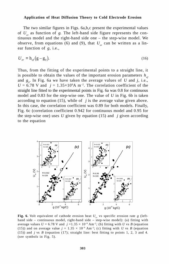
303
Application of Heat Diffusion Theory to Cold Electrode Erosion
The two similar figures in Figs. 6a,b,c present the experimental valuesof U
er as function of g. The left-hand side figure represents the con-
tinuous model and the right-hand side one – the step-wise model. Weobserve, from equations (6) and (9), that U
er can be written as a lin-
ear function of g, i.e.,
Uer = h g gef – .0 (16)
Thus, from the fitting of the experimental points to a straight line, itis possible to obtain the values of the important erosion parameters h
ef
and g0. In Fig. 6a we have taken the average values of U and j, i.e.,
U = 6.78 V and j = 1.35×10⁹A m–2. The correlation coefficient of thestraight line fitted to the experimental points in Fig. 6a was 0.8 for continuousmodel and 0.83 for the step-wise one. The value of U in Fig. 6b is takenaccording to equation (15), while of j is the average value given above.In this case, the correlation coefficient was 0.89 for both models. Finally,Fig. 6c (correlation coefficient 0.942 for continuous model and 0.95 forthe step-wise one) uses U given by equation (15) and j given accordingto the equation
Fig. 6. Volt equivalent of cathode erosion heat Uer
vs specific erosion rate g (left-hand side – continuous model, right-hand side – step-wise model): (a) fitting withaverage values U = 6.78 V and j =1.35 × 10⁻⁹ Am–2; (b) fitting with U vs B (equation(15)) and on average value j = 1.35 × 10⁻⁹ Am–2; (c) fitting with U vs B (equation(15)) and j vs B (equation (17); straight line: best fitting to points 1, 2, 3 and 4.(see symbols in Fig. 5).
0 2 4 6
0
1
2
3
4 (c)
R=0.95N=108U
er (
V)
g (10-8 kg/C)
0 2 40
1
2
R=0.832
N=108(a)
0 2 40
1
2
3
R=0.893N=108
(b)
0 2 4 6
0
1
2
3
4
(c)
R=0.942N=108U
er (
V)
g (10-8 kg/C)
0 2 40
1
2 (a)R=0.801
N=108
0 2 40
1
2 (b)R=0.887N=108
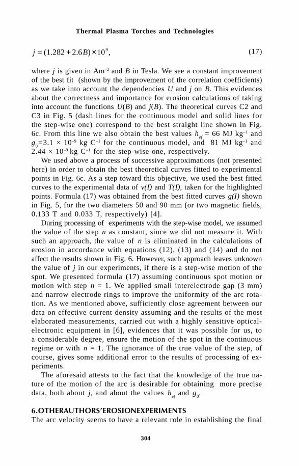
304
Thermal Plasma Torches and Technologies
j B= + ×(1.282 2.6 ) 10 ,9 (17)
where j is given in Am–2 and B in Tesla. We see a constant improvementof the best fit (shown by the improvement of the correlation coefficients)as we take into account the dependencies U and j on B. This evidencesabout the correctness and importance for erosion calculations of takinginto account the functions U(B) and j(B). The theoretical curves C2 andC3 in Fig. 5 (dash lines for the continuous model and solid lines forthe step-wise one) correspond to the best straight line shown in Fig.6c. From this line we also obtain the best values h
ef = 66 MJ kg–1 and
g0=3.1 × 10⁻⁹ kg C–1 for the continuous model, and 81 MJ kg–1 and
2.44 × 10⁻⁹ kg C–1 for the step-wise one, respectively.We used above a process of successive approximations (not presented
here) in order to obtain the best theoretical curves fitted to experimentalpoints in Fig. 6c. As a step toward this objective, we used the best fittedcurves to the experimental data of v(I) and T(I), taken for the highlightedpoints. Formula (17) was obtained from the best fitted curves g(I) shownin Fig. 5, for the two diameters 50 and 90 mm (or two magnetic fields,0.133 T and 0.033 T, respectively) [4].
During processing of experiments with the step-wise model, we assumedthe value of the step n as constant, since we did not measure it. Withsuch an approach, the value of n is eliminated in the calculations oferosion in accordance with equations (12), (13) and (14) and do notaffect the results shown in Fig. 6. However, such approach leaves unknownthe value of j in our experiments, if there is a step-wise motion of thespot. We presented formula (17) assuming continuous spot motion ormotion with step n = 1. We applied small interelectrode gap (3 mm)and narrow electrode rings to improve the uniformity of the arc rota-tion. As we mentioned above, sufficiently close agreement between ourdata on effective current density assuming and the results of the mostelaborated measurements, carried out with a highly sensitive optical-electronic equipment in [6], evidences that it was possible for us, toa considerable degree, ensure the motion of the spot in the continuousregime or with n = 1. The ignorance of the true value of the step, ofcourse, gives some additional error to the results of processing of ex-periments.
The aforesaid attests to the fact that the knowledge of the true na-ture of the motion of the arc is desirable for obtaining more precisedata, both about j, and about the values h
ef and g
0.
- . *$!The arc velocity seems to have a relevant role in establishing the final
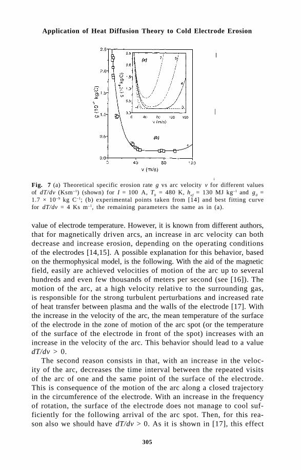
305
Application of Heat Diffusion Theory to Cold Electrode Erosion
Fig. 7 (a) Theoretical specific erosion rate g vs arc velocity v for different valuesof dT/dv (Ksm–1) (shown) for I = 100 A, T0 = 480 K, h
ef = 130 MJ kg–1 and g
0 =
1.7 × 10⁻⁹ kg C–1; (b) experimental points taken from [14] and best fitting curvefor dT/dv = 4 Ks m–1, the remaining parameters the same as in (a).
value of electrode temperature. However, it is known from different authors,that for magnetically driven arcs, an increase in arc velocity can bothdecrease and increase erosion, depending on the operating conditionsof the electrodes [14,15]. A possible explanation for this behavior, basedon the thermophysical model, is the following. With the aid of the magneticfield, easily are achieved velocities of motion of the arc up to severalhundreds and even few thousands of meters per second (see [16]). Themotion of the arc, at a high velocity relative to the surrounding gas,is responsible for the strong turbulent perturbations and increased rateof heat transfer between plasma and the walls of the electrode [17]. Withthe increase in the velocity of the arc, the mean temperature of the surfaceof the electrode in the zone of motion of the arc spot (or the temperatureof the surface of the electrode in front of the spot) increases with anincrease in the velocity of the arc. This behavior should lead to a valuedT/dv > 0.
The second reason consists in that, with an increase in the veloc-ity of the arc, decreases the time interval between the repeated visitsof the arc of one and the same point of the surface of the electrode.This is consequence of the motion of the arc along a closed trajectoryin the circumference of the electrode. With an increase in the frequencyof rotation, the surface of the electrode does not manage to cool suf-ficiently for the following arrival of the arc spot. Then, for this rea-son also we should have dT/dv > 0. As it is shown in [17], this effect

306
Thermal Plasma Torches and Technologies
is substantial only at arc velocities v > 100 m/s, which are possible formagnetically driven arcs.
Taking a linear dependence of the electrode temperature with arcvelocity, T = T
0 + v(dT/dv), where T
0 is the initial electrode tem-
perature and dT/dv = const, then for a magnetically driven arc weshould have dT/dv > 0. The other case of dT/dv < 0 can be imple-mented only with gas-dynamic arc rotation due to the supplementarycooling of the electrode with vortex flow.
Figure 7a shows theoretical plots of the erosion behavior with in-creasing arc velocity. For dT/dv > 0 there is a range of arc velocitiesfor which the specific erosion decreases, followed by some minimal levelg > g
0, and then the erosion increases with increasing velocity. Figure
7b, with data taken from [14], illustrates a qualitative comparison ofthe behavior of erosion versus arc velocity. The authors in [14] did notreport the temperature conditions of the copper cathode. They used intheir experiments electrolytic copper and pure argon–nitrogen mixtures.In our calculations we used the average values U = 6.7 V and j = 1.41×10⁻⁹A m–2 for B = 0.05T, according to equations (15) and (17), andg
0 = 1.7 × 10⁻⁹ kg C–1, according to [14]. We assumed T = 480 K and
dT/dv = 4 Ks m–1, so that f = 1 is obtained at the point of erosion transitionto the regime with g
0 = const = 1.7×10⁻⁹ kg C–1. The best agreement
of the theoretical curve with the experimental data was obtained by makingh
ef =130 MJ kg–1. The difference between these g
0 and h
ef values and
our data could be explained by the difference in materials and the presencein their gas composition of rather high concentrations of argon, whichcan cause U and j values substantially lower than for pure nitrogen or
Fig. 8. Comparison between the present step-wise erosion theory and an EDM experiment(data taken from [18]).
0 40 80 1200.0
0.5
1.0
1.5
2.0
2.5
(b)
4
g (
10 -
8 k
g/C
)
v (m/s)
0 40 80 120 1600.0
0.5
1.0
1.5
2.0
2.5
(a)
g (
10-8 k
g/C
)
v (m/s)
7 5
4
0-4

307
Application of Heat Diffusion Theory to Cold Electrode Erosion
air. As one can see in Fig. 8b, with further increase in the velocity, onecan expect an increase in the erosion. Unfortunately, the authors in [14]did not give experimental points in this region. Application of the step-wise model for the processing of the same experiments gives somewhatworse results. In the EAH the real state of motion of the arc is not eitherideally continuous or step-wise one. However, the Electrical DischargeMachining (EDM) process can provide us with periodically repeatingelectrical discharges with accurately adjustable pulse duration. Such ex-periments are reported, for example, in [18]. We disregard the valueof g
0 due to its smallness.
Using the authors data in [18] for the thermophysical properties ofsteel (in the range of temperatures from 298 K to 1808 K (melting point),λ = 56.1 Wm–lK–1, c
p= 575 J kg–1 K–1 and ρ = 7545 kg m–3) as the cathode,
for U = 4.575 V and assuming j = 2 × 10⁹ A m–2, we obtain in Fig.8 very good agreement of the step-wise model with the experimentaldata [18]. Here, c
p and ρ are the specific heat and mass density of steel,
respectively. The effective erosion enthalpy obtained for the EDM givesthe value h
ef = 4.8 MJ kg–1 – much lower than for the cathode in EAHs
(66−80 MJ kg–1). This shows that, under the conditions of EDM, thereis considerably a more effective mechanism of removal of the melt inthe spot than in the EAH. In contrast to EAHs, erosion plays a posi-tive role during electroerosion machining of materials.
/ "A simple macroscopic thermophysical model of erosion of the cold cathodehas been described. We have considered the continuous motion with constantvelocity of the arc and the step-wise (intermittent) pulsed arc discharge.We have shown that the Guile model (in the form of the Arrhenius equation)is qualitatively similar to the particular case of the thermophysical modelwith fixed values of the normalized arc velocity s and the dimensionlessstep of the arc spot n. We proposed the dimensionless parameter f tocharacterize the continuous motion erosion and f
s for the step-wise pulse
discharge erosion. We have introduced a new method, namely a thermalmethod, for the measurement of the important parameters U and j. Wehave measured these parameters for a commercial copper cathode in air,i.e., the same conditions as we have used for the erosion measurements.The obtained value of j shows rather good agreement with the best valuespublished in the literature and measured by sophisticated optoelectronicmethods.
We have shown that for a more accurate calculation of cold cath-ode erosion in EAHs with magnetic displacement of the arc, it is im-portant to consider the dependence of the volt-equivalent arc spot heat

308
Thermal Plasma Torches and Technologies
flux U and the effective arc spot current density j on the magnetic field.We also explained the unexpected behavior of erosion, observed by differentauthors, when, increasing the arc velocity can either increase or decreaseerosion. We have also shown theoretically that the nature of the mo-tion of the arc spot substantially influences the erosion: the step-wisemotion of the spot leads to the increase in the erosion in comparisonwith the continuous motion, the greater it is, the greater the length ofthe step L of the arc. A sufficiently good agreement is obtained betweenthe theory and our own and other authors’ experimental data, obtainedon EAHs and EDM equipments. As a result of processing of experi-ments with the present model, we obtained the important parameters forthe calculation of erosion, the effective enthalpy of erosion h
ef and the
specific microerosion g0. For the copper cathode of EAH in air they
are equal to approximately 70–130 MJ kg–1 and 1.7–3.1 mg C–1, de-pending on the type of copper material of the cathode and chemical com-position of plasma. For the steel cathode in the EDM process, the ef-fective enthalpy gives about 5 MJ kg–1. This demonstrates the presenceof a considerably stronger mechanism of erosion in EDM equipmentsthan in EAHs, which is expected.
0 1&",!We thank Mr. A. A. B. do Prado and Mr. J. B. Pinheiro for their technicalassistance in this work. We acknowledge the financial support of CNPq, FAPESPand FINEP of Brazil.
References1. A. Marotta and L. I. Sharakhovsky, “A theoretical and experimental in-
vestigation of copper electrode erosion in electric arc heaters. I: Thethermophysical model,” J. of Phys. D: Appl. Phys., vol. 29, pp. 2395-2403,1996.
2. E. Guile, A. H. Hitchcock, K. Dimoff, and A. K. Vijh, “Physical implicationsof an effective activation energy for arc erosion on oxidized cathodes,”J. of Phys. D: Appl. Phys., vol. 15, pp. 2341-2355, 1982.
3. L. I. Sharakhovsky, A. Marotta, and V. N. Borisyuk, “A theoretical andexperimental investigation of copper electrode erosion in electric archeaters. II: The experimental determination of arc spot parameters,”J. of Phys. D: Appl. Phys., vol. 30, pp. 2018-2025, 1997.
4. L. I. Sharakhovsky, A. Marotta, and V. N. Borisyuk, “A theoretical andexperimental investigation of copper electrode erosion in electric archeaters. III: Experimental validation and prediction of erosion,” J. ofPhys. D: Appl. Phys., vol. 30, pp. 2421-2430, 1997.
5. A. Marotta and L. I. Sharakhovsky, “Heat Transfer and Cold CathodeErosion in Electric Arc Heaters”, IEEE Transactions on Plasma Sci-ence, vol. 25, No. 5, pp. 905-912, October 1997. Special issue on highpressure arcs and high frequency thermal plasmas.

309
Application of Heat Diffusion Theory to Cold Electrode Erosion
6. V. I. Rakhovskii, “Experimental study of the dynamics of cathode spotsdevelopment,” IEEE Transactions on Plasma Science, vol. PS-4, no.2, pp. 81-102, 1976.
7. R. N. Szente, R. J. Munz, and M. G. Drouet, “The effect of low con-centrations of a polyatomic gas in argon on erosion on copper cathodesin a magnetically rotated arc,” Plasma Chemistry and Plasma Processing,vol. 7, no. 3. pp. 349- 364, 1987.
8. R. N. Szente, R. J. Munz, and M. G. Drouet, “Cathode erosion in inertgases the importance of electrode contamination,” Plasma Chemis-try and Plasma Processing, vol. 9. no. 1, pp. 121-132, 1989.
9. R. N. Szente, R. J. Munz, and M. G. Drouet, “The influence of the cathodesurface on the movement of magnetically driven electric arc,” J. of Phys.D: Appl Phys., vol. 23, pp. 1193-1200, 1990.
10. A. V. Luikov, A. V. Borovchenko, V. I. Krylovich, V. V. Toropov, L. I.Sharakhovsky, and A. S. Shaboltas, “Heat transfer in near electroderegion of the electric arc blown,” in Proc. of Int. Symp. JSME, (To-kyo), pp. 113-119, 1967.
11. V. I. Krylovich and A. S. Shaboltas, “Thermal regime of a near elec-trode region of moving electric arc. part II” Izvestiya of BSSR Acad-emy of Sciences, Ser. Phys.-Energet. Science, vol. 1, pp. 93-98, 1973.In Russian.
12. Y. S. Touloukian, R. W. Powell, C. Y. Ho, and P. G. Klements, Ther-mal Conductivity of Metallic Elements and Alloys. Vol. 1, New York,Washington: IFI/Plenum, 1970.
13. Y. S. Touloukian, R. W. Powell, C. Y. Ho, and P. G. Klements, Dif-fusivity. Vol. 10, New York, Washington: IFI/Plenum, 1973.
14. R. N. Szente, R. J. Munz, and M. G. Drouet, “Effect of the arc ve-locity on the cathode erosion rate in argon nitrogen mixtures,” J. ofPhys. D: Appl. Phys. Vol. 20, pp. 754-756, 1987.
15. A. S. Anshakov, A. N. Timoshevsky and E. A. Urbakh, “Erosion of coppercylindrical cathode in air,” Izvestya of Siberian Departament of USSRAcad. of Sci., Techn. Sci., vol. 2, no. 7, pp. 65-68, 1988. In Russian.
16. L. I. Sharakhovsky, “Experimental investigation of an electric arc motionin annular ventilated gap under the action of electromagnetic force,”J. of Eng. Phys., vol. 20, no. 2, pp. 306-313, 1971.
17. A. S. Koroteev, V. M. Mironov, and J. S. Svirchuk, Plasmatrons - design,characteristics, calculations. Moscow: Mashinostroenie, 1993. In Russian.
18. D. D. DiBitonto, P. T. Eubank, M. R. Patel, and M. A. Barruffet, “Theoreticalmodels of the electrical discharge machining process. I. A simple cathodeerosion model,” J. Appl. Phys. Vol. 66, no. 9. pp. 4095-4103, 1989

310
Thermal Plasma Torches and Technologies
H.Ts. ZayatuevGusinoozyerskaya GRES, Gusinoozyersk, Russia
One of today’s most important and challenging problems of physics ofnear-electrode processe in gas discharges is known as the ‘abnormal’emission phenomenon which is experimentally observed on thermal emissionarc discharge cathodes under inert gas conditions [1–7]. However, inspite of a variety of papers, concerned with the explanation of thisphenomenon [6–11], it might be pointed out that there are still no theoreticalinvestigations the results of which would be in close agreement withthe experimental data. In [7], the authors analysed the literature andthe results of their own investigations and concluded that the best matchedhypothesis to explain the ‘abnormal’ emission phenomenon is the hypothesisof large electronic work function eϕ changes by the Richardson–Dashmannformula [12]
j ATe
kTe = −
expϕ
, (1)
as applied to their emission from the metal to plasma. This paper indicatesthat to provide the current density and energy balance on the active surfaceof a tungsten cathode the effective electronic work function eϕ
eff at
P = 105 Pa is bound to lincrease linearly with a rise of electrode temperature.In this case, the increase of the electronic work function over 1000 Krange has been more than 1 eV, i.e. a factor of 101 over the data knownin the literature [13].
Thus, the paper [7] gives a formal explanation of the ‘abnormal’ emissionphenomenon implied in wide eϕ
eff changes with the cathode tempera-
ture, but in fact a new problem has appeared because the strong de-pendence eϕ
eff = f (T
c) is difficult to explain in the context of the classic
theory of electronic emission from the metal.
311
Emission Current Density and Electronic Work Function
Thus, the purpose of this paper is to develop the theoretical modelto provide an explanation for the linear dependence of the effective electronicwork function on cathode temperature and thereby the problem of ‘abnormal’emission as a whole.
With this aim in view, an analysis of the formula (1) and its deductioncan be performed:
(i) the formula includes the constants A and ϕ which characterizethe properties only of a solid body and values of this costant are ex-perimentally defined under high vacuum conditions. Analysis of a largeamount of information on the measurements of these constants [13] pointsto their wide scatter even for pure metals. For example, different au-thors present the measured values of the electronic work function forsingle crystal tungsten in the range from 4 to 7 eV and the range ofRichardson’s constant from 30×104 to 600×104 A/m2K2. Such strongdistinctions of the experimental data are difficult to explain especiallyin cases when Richardson’s constant is the combination of world constantsitself. The situation with compounds and alloys of metals may be thoughtof as a catastrophic one because only the deviation of the measured datadiffers of 104–105 times.
(ii) the derivation of the formula is based on the following assumptions:the first is that the electron emission is from hot metal to vacuum, i.e.under zero density condition, and the second is that electronic gas invacuum near the electrode surface, which consists of only emission electrons,and the electronic gas in metal are in thermodynamic equilibrium.
In spite of the fact that the measured results of the electronic workfunction and Richardson’s constant vary within wide limits and the formulais given only for electron emission from metal to vacuum, it is the onlyway of describing different emission phenomena on gas discharge cathodes,i.e. to describe the electronic emission from metal to a finite densitymedium. It follows that emission metal-to-plasma contact processes, i.e.in contact with the medium the density of which is greatly higher thathat of vacuum, is bound to differ essentially from the processes be-ing described by the Richardson–Dashman theory. Because of this reason,the experimental results may be differ for both A and ϕ measurementsand thermal emission current densities j
e on gas discharge cathodes.
Indeed, in the context of the assumption of thermodynamic equilibriumbetween electron gases inside and outside the metal, the electron emissionconditions can be changed in the presence of the plasma with its electroncomponent near the electrode surface.
In order to clarify the extent to which the plasma has an effect onemission processes, we consider a system of two interacting phases: electrongases of metal and plasma at the state of thermodynamic equilibrium.
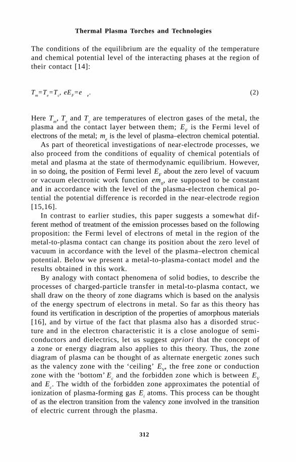
312
Thermal Plasma Torches and Technologies
The conditions of the equilibrium are the equality of the temperatureand chemical potential level of the interacting phases at the region oftheir contact [14]:
Tm=T
e=T
c, eE
F=eµ
e. (2)
Here Tm, T
e and T
c are temperatures of electron gases of the metal, the
plasma and the contact layer between them; EF is the Fermi level of
electrons of the metal; me is the level of plasma–electron chemical potential.
As part of theoretical investigations of near-electrode processes, wealso proceed from the conditions of equality of chemical potentials ofmetal and plasma at the state of thermodynamic equilibrium. However,in so doing, the position of Fermi level E
F about the zero level of vacuum
or vacuum electronic work function em0, are supposed to be constant
and in accordance with the level of the plasma-electron chemical po-tential the potential difference is recorded in the near-electrode region[15,16].
In contrast to earlier studies, this paper suggests a somewhat dif-ferent method of treatment of the emission processes based on the followingproposition: the Fermi level of electrons of metal in the region of themetal-to-plasma contact can change its position about the zero level ofvacuum in accordance with the level of the plasma–electron chemicalpotential. Below we present a metal-to-plasma-contact model and theresults obtained in this work.
By analogy with contact phenomena of solid bodies, to describe theprocesses of charged-particle transfer in metal-to-plasma contact, weshall draw on the theory of zone diagrams which is based on the analysisof the energy spectrum of electrons in metal. So far as this theory hasfound its vertification in description of the properties of amorphous materials[16], and by virtue of the fact that plasma also has a disorded struc-ture and in the electron characteristic it is a close anologue of semi-conductors and dielectrics, let us suggest apriori that the concept ofa zone or energy diagram also applies to this theory. Thus, the zonediagram of plasma can be thought of as alternate energetic zones suchas the valency zone with the ‘ceiling’ E
V, the free zone or conduction
zone with the ‘bottom’ E
c and the forbidden zone which is between E
V
and Ec. The width of the forbidden zone approximates the potential of
ionization of plasma-forming gas Ei atoms. This process can be thought
of as the electron transition from the valency zone involved in the transitionof electric current through the plasma.

313
Emission Current Density and Electronic Work Function
Figure 1 illustrates the idealised zone diagrams of the metal and theplasma prior to their contact. Metal-to-plasma contact with the sametemperature inidcates the start of the electron transition from one phase,with the higher chemical potential level, to the second phase. Figure2 shows the diagram where the solid lines indicate the case in whichthe level of the plasma electron chemical potential is above the Fermipotential of the metal. In this case, the electrons will transfer from plasmainto metal and the transition will continue until the levels of both phasesbecome equal. As a result, external contact potential difference V
c occurs
between the plasma and the metal or a potential difference takes placebetween their surfaces in the surrounding space. The internal potentialdifference in the immediate metal-to-plasma contact region is zero. Thebroken lines are the case when the Fermi metal level is above the levelof the plasma electron gas chemical potential.
This special feature of the plasma zone structure, i.e. the presenceof forbidden zone and conduction zone, determines the value of the electronicwork function from metal to plasma eϕ
e that matches the position of
the electron gas chemical potential level of near-electrode plasma withan accuracy of the width of the conduction zone E
c (see Figs.2 and 3),
i.e.
eµe≈eϕ
eff. (3)
This is caused by the fact that the electrons can transfer from metalonly into the plasma conduction zone since the portion of the energetic
0 0 c
ϕo µ i
F ≈ ≈ V
Fig.1. Idealised energetic (zone) diagrams of metal and plasma before contact.EF is the Fermi level of metal electrons; eϕ 0 is electronic work function ofmetal in vacuum (vacuum work function); me is the chemical potential levelof the plasma electron gas; Ei is the potential plasma-forming gas atom ionisationor the width of the plasma forbidden zone; EV is the ceiling of plasma va-lency zone; Ec is the bottom of plasma conduction zone.
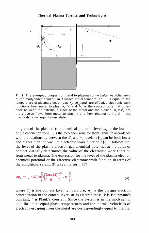
314
Thermal Plasma Torches and Technologies
Vc 0 0 nv nvec Vc
ϕeff
ϕ ϕeff µ
≈ ≈
diagram of the plasma from chemical potential level me to the bottom
of the conduction zone Ec is the forbidden zone for them. Thus, in accordance
with the relationship between the EF and m
e levels, eϕ
eff can be both lower
and higher than the vacuum electronic work function eϕ0. It follows that
the level of the plasma electron gas chemical potential at the point ofcontact virtually determines the value of the electronic work functionfrom metal to plasma. The expression for the level of the plasma electronchemical potential or the effective electronic work function in terms ofthe conditions (2 and 3) takes the form [17]:
e e kTm kT
hne e c
e cecϕ µ π≈ =
ln //
22
2
3 2
, (4)
where Tc is the contact layer temperature; n
ec is the plasma electron
concentration in the contact layer; me is electron mass; k is Boltzmann’s
constant; h is Plank’s constant. Since the system is in thermodynamicequilibrium at equal phase temperatures and the thermal velocities ofelectrons escaping from the metal are correspondingly equal to thermal
Fig.2. The energetic diagram of metal to plasma contact after establishmentof thermodynamic equilibrium. Surface metal temperature Tm is equal to thetemperature of plasma electron gas Te, eϕeff and are effective electronic workfunctions from metal to plasma; Vc and Vc
’ is the contact potential differ-ence between the external surface of the metal and the plasma; nec× vec arethe electron flows from metal to plasma and from plasma to metal in thethermodynamic equilibrium state.

315
Emission Current Density and Electronic Work Function
velocities of plasma electrons, nec
determines the concentration of boththe electron flow from plasma to metal and of the electron flow frommetal to plasma. Then, when substituting (4) into the Richardson–Dashmanformula (1), the expression for the current density of the electron emissionfrom metal to plasma is:
j enkT
men ve
EMec
c
eec ec=
=
2
1
4
1 2
π
/
. (5)
Here vec is the mean thermal velocity of the emitted electrons whichagrees with the contact layer temperature or electrode surface temperature.It follows that this expression is in line with the formula for the cur-rent density of electrons in motion with the mean thermal velocity vecwhich agrees with the cathode temperature.
In real systems, the plasma temperature is practically always higherthan the electrode temperature, and not only electroncs but also ionstake part in electric current transition in plasma. As a consequence ofthe ambipolar diffusion of electrons and ions from plasma to metal, theinternal contact potential difference V
f is formed between them. The
conditions of thermodynamic equilibrium in this case are written onlyfor the contact layer through which the exchange with particles takesplace itself. The concentration of electrons nM
ec escaping from the metal
is equal to the concentration of electrons necP arriving from plasma to
the surface of the metal through the potential barrier Vf. The difference
between the electron flows out of the metal and the plasma is causedby different values of their thermal velocities is equalized by the fluxof thermal ions from the plasma. The concentration nM
ec = n
ecP = n
ec is de-
termined by the formula:
n neV
kTec ef
e
= −
0 exp (6)
Here ne0
and Te are the concentration and temperature of the perturbed
near-electrode plasma–electron gas; Vf is the contact potential differ-
ence the value of which is deduced from the condition of equality ofthe total current density to zero to the electrode surface:
j j jeem
iT eTrev+ − = 0. (7)
While writing this expression to solve it for current densities (6),

316
Thermal Plasma Torches and Technologies
we shall present the equation (7) as:
14
8 8 14
00
1 2 1 2
0
1 2
enkT
m
kT
m
eV
kTen
kT
Mec
e
e
e
f
ei
i
π π π
−
+
=/ / /
exp . (8)
Here M is the ion mass of the plasma-forming gas; Ti and n
i0 are
the temperature and concentration of near-electrode plasma ions. Solving(8) in relation to eV
f, we obtain an expression for internal contact potential
difference
eV kTMT
m T
n
n
T
Tf ee i
e
i
c
e
e=
−
ln
0
01 . (9)
The substitution of (9) into (4) and (5) gives the expression for theelectronic work function:
e kT
m T
h
MT
m T
T
T
ne c
e c e
e i
c
e
io
ϕ
π
=
−
ln
/
22
12
3 2
, (10)
and the formula for the current density of thermal emission of electronsfrom metal to plasma:
j An TT
T
T
Teem
i ee
i
c
e
= −
0
1 2 1/, (11)
where A=e(k/2pM)1/2 is the plasma-forming gas emission constant.Figures 3 and 4 give dimensionless values of electric work function
and thermal emission current density defined by the equations (10) and(11). As illustrates by curves presented they are in agreement with dataof paper [7].

317
Emission Current Density and Electronic Work Function
Fig.3. Dependence of dimensionless work function on the plasma and cathodetemperature.
∼
jc 102 101 100
0.2 0.4 0.6 0.8 Tc/Te
Fig.4. Dependence of relative current density of the electron thermal emissionon the cathode and plasma temperature.
REFERENCE1. S.V.Lebedev and S.Z.Khaikin, J. of Experimental and Theoretics Physics,
Vol.26, No.6, pp.723-735 (1954) (in Russian).2. V.K.Rokhadgi, Raketnaya Tekhnika i Kosmonavtika, Vol.4, No.10, pp.214-
216 (1966) (in Russian).
318
Thermal Plasma Torches and Technologies
3. A.M.Dorodnov, N.P.Kozlov and Ya.A.Pomelov, Thermophysics of HighTemperatures, Vol.9, No.3, pp.483-487 (1971) (in Russian).
4. S.V.Lebedev, Thermophysics of High Temperatures, Vol.11, No.5, pp.986-994 (1973) (in Russian).
5. V.N.Anikeyev, Izvestiya Sibirskogo Otdeleniya USSR Ac. Sci., Ser. ofTech. Sci., No.3, Issue 3, pp.60-67 (1981) (in Russian).
6. A.A.Portnikov, V.A.Petrosov and I.N.Ostretsov, Phizika i primeneniyeplazmennykh uskoritelyei, Minsk, Nauka i Tekhnika, pp.239-260 (1974)(in Russian).
7. S.P.Vaschenko, G.-N.B.Dandaron, M.F.Zhukok and Kh.Ts.Zayatuev, SibirskiiFiziko-Tekhnicheskii Zhurnal, No.1, pp.98-106 (1992) (in Russian).
8. B.Ya.Moizhes and B.A.Nemchinskii, Zhurnal Tekhnicheskoi Fiziki, Vol.44,No.12, pp.2539-2547 (1974) (in Russian).
9. V.L.Ginsburg and V.P.Shabanskii, Doklady USSR Ac. Sci., Vol.100, No.3,pp.445-448 (1981) (in Russian).
10. M.P.Zektser, Thermophysics of High Temperatures, Vol.13, No.3, pp.491-496 (1975) (in Russian).
11. A.P.Nevskii, A.I.Sharakhovskii and B.B.Rodkevich, Vzaimodeistviye dugis elektrodami plazmotrona, Minsk, Nauka i Tekhnika (1982) (in Rus-sian).
12. I.N.Ostretsov, V.A.Petrosov, A.A.Potrnikov and B.B.Rodkevich, ZhurnalPrikladnoi Mekhaniki i Tekhnicheskoi Fiziki, No.1, pp.162-164 (1974)(in Russian).
13. V.S.Fomenko and I.A.Podchernyaeva, Emissionnye i Adsobtsionnye SvoistvaVeschestv i Materialov, Moscow, Atomizdat (1975) (in Russian).
14. R.Kheibud, Termodinamika Ravnovesnykh Protsessov, Moscow, Mir Pub-lishing (1983) (in Russian).
15. F.G.Bakht and V.G.Yur’ev, Zhurnal Tekhnicheskoi Fiziki, Vol.49, No.5,pp.905-944 (1979) (in Russian).
16. A.Phel’ts, Amorphnye i Stekloobraznye Neorganicheskiye Tvyerdye Tela,Moscow, Mir Publishing (1986) (in Russian).
17. V.L.Granovskii, Electricheskii Tok v Gaze. Ustanovivshiisya Tok, Moscow,Nauka Publishing (1973) (In Russian).
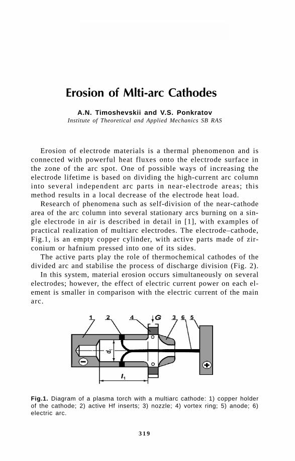
3 1 9
Erosion of Multi-arc Cathodes
A.N. Timoshevskii and V.S. PonkratovInstitute of Theoretical and Applied Mechanics SB RAS
Erosion of electrode materials is a thermal phenomenon and isconnected with powerful heat fluxes onto the electrode surface inthe zone of the arc spot. One of possible ways of increasing theelectrode lifetime is based on dividing the high-current arc columninto several independent arc parts in near-electrode areas; thismethod results in a local decrease of the electrode heat load.
Research of phenomena such as self-division of the near-cathodearea of the arc column into several stationary arcs burning on a sin-gle electrode in air is described in detail in [1], with examples ofpractical realization of multiarc electrodes. The electrode–cathode,Fig.1, is an empty copper cylinder, with active parts made of zir-conium or hafnium pressed into one of its sides.
The active parts play the role of thermochemical cathodes of thedivided arc and stabilise the process of discharge division (Fig. 2).
In this system, material erosion occurs simultaneously on severalelectrodes; however, the effect of electric current power on each el-ement is smaller in comparison with the electric current of the mainarc.
Fig.1. Diagram of a plasma torch with a multiarc cathode: 1) copper holderof the cathode; 2) active Hf inserts; 3) nozzle; 4) vortex ring; 5) anode; 6)electric arc.

3 2 0
Thermal Plasma Torches and Technologies
So, it is now possible to reach high current load on thermo-chemical compound electrodes and extend their lifetime at the sametime [2].
Transition to the stationary division of the arc and a uniformelectric current distribution in the active elements made of Zr andHf takes place over a period of time. It is connected with either thedynamics of gas flows in the electrode cavity or with the heating upof the oxide–nitride layer (dielectric) which generates in air undercathode spots on the insert surfaces. Transition processes occuringat the moment of arc connection have an effect on the erosion char-acteristics of even ordinary thermochemical cathodes; because ofthis reason, it was essential to carry out experiments to examinethese regimes for multiarc electrodes.
The experiments were carried out in a plant using a plasma torchfor metal cutting (Fig.1). Six Hf inserts with a diameter of 2.5 mmwere pressed (uniformly around it) into a copper electrode with aninner diameter of 12 mm. With these geometrical dimensions of thecathode and the nozzle (diameter 7 mm), and at an air flow rate of2–2.5 g/s, the dividing current was 120–150 A; it determined thenumber of discharge n stable zones for the given common currentI = nI
c. During the experiments, in addition to recording the period
of changes of common current, high-speed filming was carried outof the arc behaviour in the inner cathode cavity. Figure 3a, b showsthe curves of arc current changes with time and the corresondingnumber of stable stationary discharge zone.. The current increasetime constant was defined by the power mains; ballast waterrheostats and inductivity were included there. Films were analyzedto describe the mechanism of discharge development. The followingresults were obtained: ignition of a discharge in the gap between thecathode and the output anode; connection of the main discharge and
Fig.2. Arc division in the cathode cavity I = 680 A.

3 2 1
Erosion of Multi-arc Cathodes
gradual movement of the cathode root along the inner electrode sur-face to the zone containing the inserts; this results in the rotationof the radial part of the arc. Nonstationary division occurs at thismoment; it is characterized by acts of unstable movement of arcspots and is followed by a stationary regime. During the movementof cathode spots along the holder material one can see erosion ofcopper which is ejected from near-cathode areas with streams. It ispossible to conclude that the electric current intensity determinesthe dynamics of arc self-dividsion. When I > 450–500 A, ‘connec-tion’ of stationary roots takes place gradually (as a rule) duringquite a long period of time of ~ 0.6 s, though at least three rootsmay exist after ~0.1 s (Fig. 3a). Faster transition to the division re-gime occurs at lower arc current (Fig. 3b).
Fig.3. Change of electric current I and the number of divided arcs n in thecathode with: a) I = 620 A, b) 400, c) 530 (step start).
Division into three roots is observed often; however, one of theroots disappears and appears again only when the current provid-ing stability is reached. This transition trend is likely to be ex-plained by the influence of copper vapours upon gas-dynamics andby the method of preparation of emission insert layers; increasingstarting current increases the amount of copper vapours generated.As shown in [3], the surface layer of a hafnium insert consistsmainly of hafnium oxides and nitrides. Their emission features maydevelop only with temperatures of about 2 000 K. According to theexperimentally obtained dependence of the heat flux into the cath-ode on current, the heating time of the insert surface up to this tem-perature is in the range from 10 s ( I = 100 A) to 0.05 s(I = 700 A); the duration of current rise up to the set value is 1–2 s. In this process, the cathode spots are usually retained in the
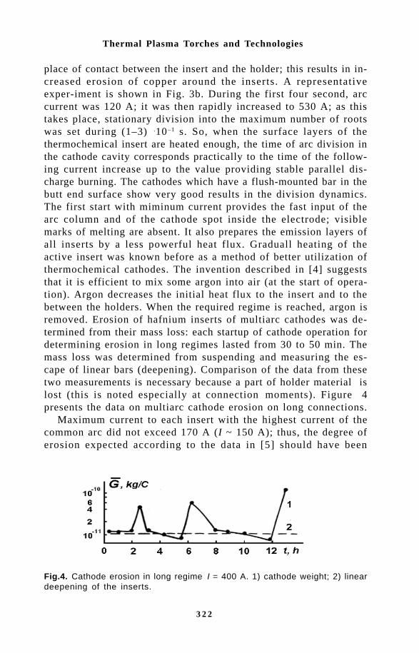
3 2 2
Thermal Plasma Torches and Technologies
place of contact between the insert and the holder; this results in in-creased erosion of copper around the inserts. A representativeexper-iment is shown in Fig. 3b. During the first four second, arccurrent was 120 A; it was then rapidly increased to 530 A; as thistakes place, stationary division into the maximum number of rootswas set during (1–3) .10–1 s. So, when the surface layers of thethermochemical insert are heated enough, the time of arc division inthe cathode cavity corresponds practically to the time of the follow-ing current increase up to the value providing stable parallel dis-charge burning. The cathodes which have a flush-mounted bar in thebutt end surface show very good results in the division dynamics.The first start with miminum current provides the fast input of thearc column and of the cathode spot inside the electrode; visiblemarks of melting are absent. It also prepares the emission layers ofall inserts by a less powerful heat flux. Graduall heating of theactive insert was known before as a method of better utilization ofthermochemical cathodes. The invention described in [4] suggeststhat it is efficient to mix some argon into air (at the start of opera-tion). Argon decreases the initial heat flux to the insert and to thebetween the holders. When the required regime is reached, argon isremoved. Erosion of hafnium inserts of multiarc cathodes was de-termined from their mass loss: each startup of cathode operation fordetermining erosion in long regimes lasted from 30 to 50 min. Themass loss was determined from suspending and measuring the es-cape of linear bars (deepening). Comparison of the data from thesetwo measurements is necessary because a part of holder material islost (this is noted especially at connection moments). Figure 4presents the data on multiarc cathode erosion on long connections.
Maximum current to each insert with the highest current of thecommon arc did not exceed 170 A (I ~ 150 A); thus, the degree oferosion expected according to the data in [5] should have been
Fig.4. Cathode erosion in long regime I = 400 A. 1) cathode weight; 2) lineardeepening of the inserts.
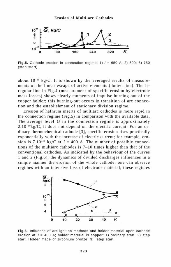
3 2 3
Erosion of Multi-arc Cathodes
about 10–11 kg/C. It is shown by the averaged results of measure-ments of the linear escape of active elements (dotted line). The ir-regular line in Fig.4 (measurement of specific erosion by electrodemass losses) shows clearly moments of impulse burning-out of thecopper holder; this burning-out occurs in transition of arc connec-tion and the establishment of stationary division regime.
Erosion of hafnium inserts of multiarc cathodes is more rapid inthe connection regime (Fig.5) in comparison with the available data.The average level G in the connection regime is approximately2.10–10kg/C; it does not depend on the electric current. For an or-dinary thermochemical cathode [3], specific erosion rises practicallyexponentially with the increase of electric current; for example, ero-sion is 7.10–10 kg/C at I = 400 A. The number of possible connec-tions of the multiarc cathodes is 7–10 times higher than that of theconventional cathodes. As indicated by the behaviour of the curves1 and 2 (Fig.5), the dynamics of divided discharges influences in asimple manner the erosion of the whole cathode: one can observeregimes with an intensive loss of electrode material; these regimes
Fig.5. Cathode erosion in connection regime: 1) I = 650 A; 2) 800; 3) 750(step start).
Fig.6. Influence of arc ignition methods and holder material upon cathodeerosion at I = 400 A; holder material is copper: 1) ordinary start; 2) stepstart. Holder made of zirconium bronze: 3) step start.
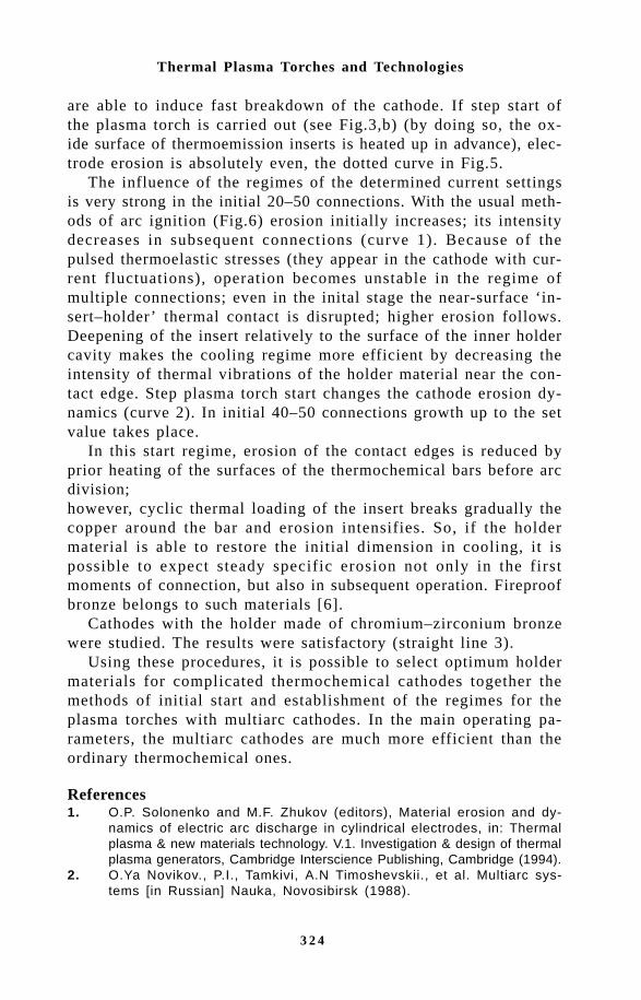
3 2 4
Thermal Plasma Torches and Technologies
are able to induce fast breakdown of the cathode. If step start ofthe plasma torch is carried out (see Fig.3,b) (by doing so, the ox-ide surface of thermoemission inserts is heated up in advance), elec-trode erosion is absolutely even, the dotted curve in Fig.5.
The influence of the regimes of the determined current settingsis very strong in the initial 20–50 connections. With the usual meth-ods of arc ignition (Fig.6) erosion initially increases; its intensitydecreases in subsequent connections (curve 1). Because of thepulsed thermoelastic stresses (they appear in the cathode with cur-rent fluctuations), operation becomes unstable in the regime ofmultiple connections; even in the inital stage the near-surface ‘in-sert–holder’ thermal contact is disrupted; higher erosion follows.Deepening of the insert relatively to the surface of the inner holdercavity makes the cooling regime more efficient by decreasing theintensity of thermal vibrations of the holder material near the con-tact edge. Step plasma torch start changes the cathode erosion dy-namics (curve 2). In initial 40–50 connections growth up to the setvalue takes place.
In this start regime, erosion of the contact edges is reduced byprior heating of the surfaces of the thermochemical bars before arcdivision;however, cyclic thermal loading of the insert breaks gradually thecopper around the bar and erosion intensifies. So, if the holdermaterial is able to restore the initial dimension in cooling, it ispossible to expect steady specific erosion not only in the firstmoments of connection, but also in subsequent operation. Fireproofbronze belongs to such materials [6].
Cathodes with the holder made of chromium–zirconium bronzewere studied. The results were satisfactory (straight line 3).
Using these procedures, it is possible to select optimum holdermaterials for complicated thermochemical cathodes together themethods of initial start and establishment of the regimes for theplasma torches with multiarc cathodes. In the main operating pa-rameters, the multiarc cathodes are much more efficient than theordinary thermochemical ones.
References1. O.P. Solonenko and M.F. Zhukov (editors), Material erosion and dy-
namics of electric arc discharge in cylindrical electrodes, in: Thermalplasma & new materials technology. V.1. Investigation & design of thermalplasma generators, Cambridge Interscience Publishing, Cambridge (1994).
2. O.Ya Novikov., P.I., Tamkivi, A.N Timoshevskii., et al. Multiarc sys-tems [in Russian] Nauka, Novosibirsk (1988).

3 2 5
Erosion of Multi-arc Cathodes
3. M.F. Zhukov, A.V.Pustogarov, G.-N.B. Dandaron, A.N. Timoshevskii,Thermochemical cathodes [in Russian], Institute of ThermophysicsSB RAS, Novosibirsk (1985).
4. Patent 847598 USSR, ICI B23K 9/16 Way of plasma treatment// BykhovskiiD.G., Kunin V.S. et al. Zhukov M.F., Kozlov N.P., Pustogarov A.B. etal. Near-electrode processes in arc discharges [in Russian] Nauka,Novosibirsk (1982).
5. V.G. Osinzev, A.I. Grigoriev, Yu.V. Kurochkin, et al, Izvestiya SB RAS,4, No.15, (1987).

3 2 6
Thermal Plasma Torches and Technologies
U.B. Ashimov., E.A. Abdrachmanov, G.D. Manapova andT.S. Maldybaeva
Kazakh National Technical University, 480013, Almaty, Kazakhstan
The three-phase electric arc, generated by special electric arc installationsis used widely in a number of technological processes of metallurgical,chemical and building industries, superseding traditional technologiesat the expense of increase of productivity, capacity, reduction of processesstages, and other.
The characteristic of three-phase electric arc units is generationby electric arcs of higher harmonic components of currents and voltagein supply circuits which negatively influences the quality of electricpower [1].
The higher harmonics, generated by electric arcs, have a strongeffect on quality parameeters of electric power, such as the non-sinusoidalwave of the form of the voltage curve in AC circuits, on technologicalparameters of electroreceivers, connected to them, and also on thework of electric arc units. So, for example, they result in large difficultiesin automatic control, as the measuring bodies of electronic regula-tors react to the effect of current and voltage, with the latter greatlydeformed by higher harmonics [2].
Certain amount of research has been carried out the field of metallurgyon higher harmonic components of current and voltage of electricsteelmelting furnaces. The dependences of levels and spectral structureof higher harmonics of three-phase arcs on the electrical and tech-nological parameters and work conditions of furnaces have beenestablished.
Recently, the three-phase arc has been considered widely in the‘know-how’ of electromelted oxide refractory materials. The production

3 2 7
Influence of Three-Phase Electric Arcs Burning on Oxide Melts
of these materials comes true in three-phase electric-arc furnaces asOKB-2126, 2130, RKZ-4, RKZ-6 and other ones, specially devel-oped for these purposes.
As against metal, oxide refractory materials are characterized byhigher melting point, no conductivity in the solid state, and their meltshave low electric- and thermal conductivity, high viscosity [3]. Thesespecific properties stipulate special features of burning of three-phaseelectric arcs on oxide refractory melts and generation of higher harmonicsof currents and voltage.
Therefore,, it is essential to carry out experimental research ofthe spectral structure of higher harmonics of currents and voltage,generated by three-phase electric arcs, burning on oxide melts, re-veal the laws of changes of the structure and levels of higher har-monics in relation to the electrical and technological parameters andworking conditions of mining and thermal furnaces.
Experimental research of higher harmonic components of currentsand voltage, generated by three-phase electric arcs, burning on oxidemelts, were conducted in an integrated laboratory three-phase four-electrode furnace with a rectangular bath and a linear electrode block(with a split phase A on outer electrodes), capacity 150 kVA andon the industrial furnace RKZ-4, capacity 4 kVA.
During experimental melting, we recorded and measured the signalsof current and voltage with the help of the measuring-registrationcircuit, developed on the basis of the analysis of systems existingin metallurgy and electric power industry, the including pick-up unitof current and voltage, multichannel magnetograph K-067, oscillographsN8-13, six-channel self-recorder K-338, analyzer of harmonics. Theresearched electrical signals, reduced with the help of dividers upto 0.5-1 V, were written down on magnetic tape of seven-channelmagnetograph K-067 and paper tape of A-338 automatic recordingsystems (Fig.1).
Processing the experimental data, the calculation of the harmonicstructure of current and voltage were conducted with the help of systemsspecially developed for these purposes for processing the informa-tion from magnetographs and a program of parameter calculation ofhigher harmonics (Fig. 2).
Experimental melting in the three-phase four-electrode furnace wasconducted at a voltage of U = 100–140 V, current I = 300–450 A,length of disintegration of electrodes L
d = 85-120 mm, length of arc
La = 10/30 mm. As a charge we used basalt rock.Figures 3 and 4 show the characteristic oscillograms of phase current
and voltage, recorded during experimental melting. As indicated by
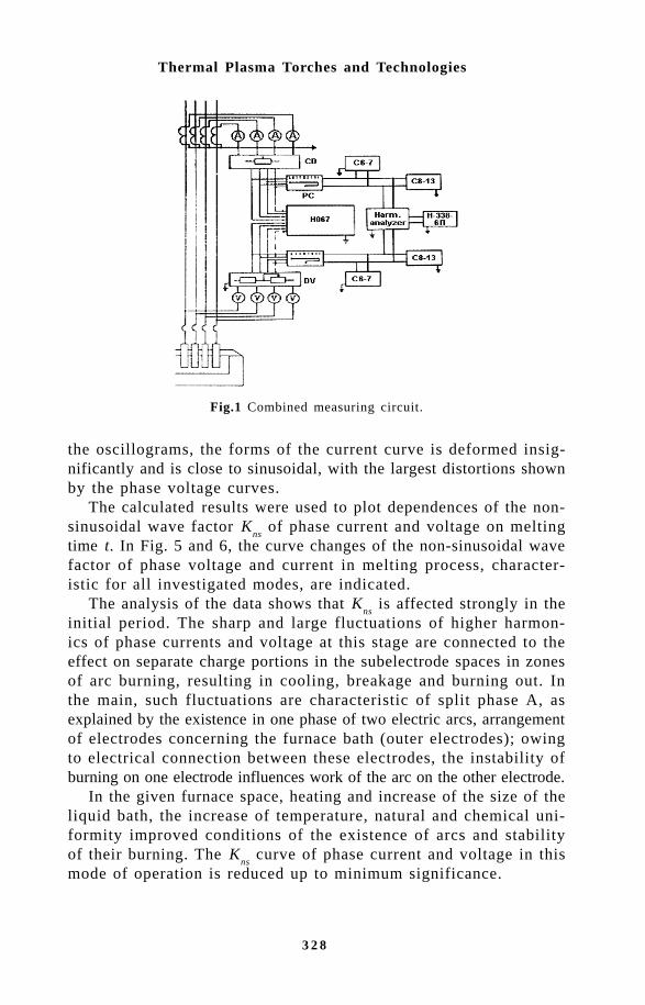
3 2 8
Thermal Plasma Torches and Technologies
the oscillograms, the forms of the current curve is deformed insig-nificantly and is close to sinusoidal, with the largest distortions shownby the phase voltage curves.
The calculated results were used to plot dependences of the non-sinusoidal wave factor K
ns of phase current and voltage on melting
time t. In Fig. 5 and 6, the curve changes of the non-sinusoidal wavefactor of phase voltage and current in melting process, character-istic for all investigated modes, are indicated.
The analysis of the data shows that Kns
is affected strongly in theinitial period. The sharp and large fluctuations of higher harmon-ics of phase currents and voltage at this stage are connected to theeffect on separate charge portions in the subelectrode spaces in zonesof arc burning, resulting in cooling, breakage and burning out. Inthe main, such fluctuations are characteristic of split phase A, asexplained by the existence in one phase of two electric arcs, arrangementof electrodes concerning the furnace bath (outer electrodes); owingto electrical connection between these electrodes, the instability ofburning on one electrode influences work of the arc on the other electrode.
In the given furnace space, heating and increase of the size of theliquid bath, the increase of temperature, natural and chemical uni-formity improved conditions of the existence of arcs and stabilityof their burning. The K
ns curve of phase current and voltage in this
mode of operation is reduced up to minimum significance.
Fig.1 Combined measuring circuit.
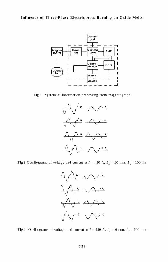
3 2 9
Influence of Three-Phase Electric Arcs Burning on Oxide Melts
Fig.2 System of information processing from magnetograph.
Fig.3 Oscillograms of voltage and current at I = 450 A, Lg = 20 mm, L
d = 100mm.
Fig.4 Oscillograms of voltage and current at I = 450 A, La = 0 mm, L
d = 100 mm.

3 3 0
Thermal Plasma Torches and Technologies
Fig.5 Curve changes of non-sinusoidal wave factor of phase voltage.
Fig.6 Curve changes of non-sine wave factor of phase current.
With melting of the charge, the arcs gradually open, increase insize and mobility. Intensive heat exchange of arcs with the environment,their cooling and decrease of stability of arc burning explain someincrease of fluctuations of harmonics of current and voltage at thisstage of the melting process.
As shown by the results of research, the most significant term inthe harmonic spectrum of both current and voltage is the third harmonics.The third harmonic of phase voltage depending on melting stages changein the interval (7.9–59.8) %, and current in the interval (1.1–7.8)%.
The increase of current in electrodes from 300 up to 450 A re-duces the level of higher harmonic components of voltage with (20-32)% up to (12–26) %, and current with (2.8–11)% up to (1.0–9.5)

3 3 1
Influence of Three-Phase Electric Arcs Burning on Oxide Melts
%, is connected with increase of temperature and improvement of thestability of arc burning.
With increase of the length of electrode disintegration, irrespec-tive of the size of the entered capacity, the contents of higher har-monics, especially third harmonics, in the phase current and volt-age grows in the initial melting moment. It is connected with increaseof the active resistance of the bath in the interelectrode space, whichhinders firing of the furnace and results in stable arc burning.
It is necessary to note that in all modes of operations of electricarc installation the level K
ns of phase voltage is above that of the
phase current. It is confirmed by the oscillograms of phase currentsand voltage.
The research of the laws of generation of higher harmonics by three-phase electric arcs on an RKZ-4 industrial mining-thermal furnaceRKZ-4 was conducted at various electrical modes of its work: U =249–281 V, I = 9–10 kA.
Figure 7-12 show the characteristic recorded plots of higher harmonicsof current and voltage indicated by the work of the furnace trans-former on 5 steps (U = 281 V, I = 910 kA).
– the start of melting (the period of loading and after-loading mode).This period is characterized by sharp and large fluctuations of higherharmonics of current and voltage. Duration t = 30–35 min, the non-sinusiodal wave factor of current K
ns = (4.5–7.0–18–30) %, the non-
sinusoidal wave factor of voltage Kns
= (2.0–3.5–6.0–10.0) %. Theduration of the mode depends on the quantity and mode of chargeloading;
– the mode of quiet arc burning. It is characterized by minimumfluctuations of higher harmonics. Duration t = 35–40 min, K
ns = (4.0-
5.0 – 11,0) %. The levels of higher harmonics grow up to the endof the mode;
Fig.7 Recording of the 3rd, 5th harmonics of voltage at charge loading.
Fig.8 Recording of the 3rd, 5th harmonics of voltage in the quiet arc burning.
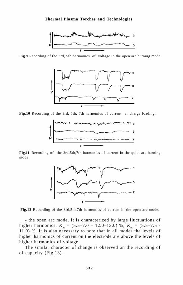
3 3 2
Thermal Plasma Torches and Technologies
Fig.9 Recording of the 3rd, 5th harmonics of voltage in the open arc burning mode
Fig.10 Recording of the 3rd, 5th, 7th harnomics of current ar charge loading.
Fig.11 Recording of the 3rd,5th,7th harmonics of current in the quiet arc burningmode.
Fig.12 Recording of the 3rd,5th,7th harmonics of current in the open arc mode.
- the open arc mode. It is characterized by large fluctuations ofhigher harmonics. K
ns = (5.5–7.0 – 12.0–13.0) %, K
ns = (5.5–7.5 -
11.0) %. It is also necessary to note that in all modes the levels ofhigher harmonics of current on the electrode are above the levels ofhigher harmonics of voltage.
The similar character of change is observed on the recording ofof capacity (Fig.13).

3 3 3
Influence of Three-Phase Electric Arcs Burning on Oxide Melts
The period of significant fluctuation of capacity at the beginningof melting, stipulated by charge loading with heating of the bath andmelting of part of the charge, is replaced by the plot of rather quietallocation of capacity. With opening of an arc new fluctuations ofcapacity begin.
In Fig. 14 and 15 the curve changes of the non-sinusoidal wavefactor of phase current and voltage of the REZ-4 furnace in the meltingprocess of corundum refractories are shown
Fig.13 Recording of capacity.
Fig.14 Curve changes of non-sinusoidal wave factor of phase current.
The comparative analysis of the dependence of levels and char-acters of changes of the maximum harmonics of current and volt-age in relation to the technological stages of the melting process inthe RKZ-4 industrial furnace and laboratory three-phase four-electrodefurnace shows that the changes of the non-sinusoidal wave factorsare similar and have general laws. The revealed laws of the changeof the spectral structure, levels and nature of fluctuation of higher

3 3 4
Thermal Plasma Torches and Technologies
Fig.15 Curve changes of non-sinusoidal wave factor of phase voltage.
harmonics of currents and voltage in the melting process of oxidematerials are determined by physico-chemical processes, occurringin the furnace bath and by the position of electrodes in relation tothe charge and the bath. It allows to identify the condition of thefurnace bath (form, sizes, natural and chemical uniformity, temperature)under the characteristics of higher harmonics of current and volt-age and use them as informative parameters, determining the indi-vidual stages of the corundum melting process.
Thus, the research results are of interest not only for the devel-opment of measures for decreasing the higher harmonics of currentand voltage in circuits with three-phase electric arcs, but also forsystem engineering in the automatic control of melting processes ofoxide materials.
References1. Smelyansky M.Ya., Mineev R.K. Influence of electric arc furnaces
on systems of electric supply. - Moscow, Energia, 1975.2. Mineev R.K., Micheev À.P., Ryzhnev Yu.L. Efficiency increase of electric
supply of electric furnaces. - Moscow, Energoatomizdat, 1986.3. Strelov K.K., et al. Technology of refractory materials. - Moscow, Metallurgy,
1988.
335
Modelling of Flow Stabilization by the Swirl of a Peripheral Flow...
E.P. Volchkov, V.P. Lebedev, V.I. Terekhov and N.E. ShishkinInstitute of Thermophysics, Siberian Branch, Russian Academy of Sciences,Novosibirsk, Russia
!"#$ !The gas-swirl stabilization of plasma jets is one of effective methodsof its retention in the near-axial area of channels in generators oflow-temperature plasma [1]. Except the effect of gas-dynamiccompression, the peripheral swirl allows to solve another urgent problem- to protect the reactor walls from the heat influence of the plasmajet [2,3]. Swirl flows are also used for the flow structure formationand control of the heat and gas-dynamic characteristics of differentpower devices and apparatuses, using high-temperature working media:in swirl furnaces and burners, in aviation engines, etc. [4,6]. Investigationsshow that during swirl stabilization the gas-dynamic structure of theflow influences significantly the spatial stability of the plasma columnand its characteristics.
The main difficulty, arising during the design of the devices withswirl retention of plasma jets or flames, is poor knowledge of theaerodynamics and heat and mass transfer processes in these devices.The stabilization process is extremely sensitive to the change of regimeand geometrical parameters. Thus, the determination of the boundariesof the stable localization of high-temperature jets is necessary forthe prediction of the optimal regime parameters for plasma torchesand plasma-chemical reactors.
The problem under consideration is very complicated. The three-dimensional character of the flow is accompanied by the impact ofa strong field of centrifugal forces on the transfer processes. Theanisothermal nature of the flow can affect significantly the mixing
336
Thermal Plasma Torches and Technologies
of flows. This is confirmed by investigations in this field [5,7-9].The process of gas-dynamic stabilization of a jet in the near-axial
area can be explained using the concepts of the stability mechanismin rotating flows. Available experimental data on the turbulence structurein rotating flows [8,10-12] demonstrate the drastic decrease of ve-locity pulsation in areas with damping of turbulent exchange. Thatis why the jet localization process in the near-axial area will be affectedby the flow laminarization in a layer of mixing under the action ofthe mass forces field.
In general, the formation conditions of these areas in swirled flowsare known now [4,8,13,14]. They follow from the principle of theflow stability in the field of mass forces, formulated by Raleigh. Ac-cording to this principle, the necessary conditions of turbulence dampingare circulation and density distribution over the radius ∂Γ/∂r > 0 and∂ρ/∂r>0.The intensification of turbulent transfer will occur withreverse signs of circulation and density gradients.
We would like to notice one more important condition, influencingthe processes of jet mixing in swirl flows. The swirl of the peripheralstabilizing jet leads to the gradient increase of the total averaged velocity.According to the existing ideas concerning the mechanism of turbulentenergy generation [8,15], this factor must lead to intensification ofmixing, deteriorating the thermal insulation of the plasma jet fromchamber walls.
Thus, three main factors will influence the mechanism of plasmaretention: the damping of the turbulent transfer at the expense of cen-trifugal forces, buoyancy forces, resulting from the density gradi-ent over the radius, and mixing intensification due to the increaseof the total velocity gradient in the swirl flow as well. In [9,13-16]experimental estimates of each factor contribution during stabilizationof jets with different density in vortex chambers were performed.
However, these data cannot be considered as exhaustive ones, becausethey do not illustrate the variety of swirl flow interaction. The greatinfluence on mixing processes as a whole will be caused by the flowboundedness, characteristic for the flow interaction in a vortex chamber.Boundary layers, forming at the side and front walls, can lead to acardinal restructuring of the flow. According to experimental data[17,18], the size relation of peripheral and near-axial jets and rimthickness, separating these jets, affect the flow formation.
The creation of reliable methods for the calculation of jet developmentwith gas-swirl stabilization meets some principal difficulties. Firstof all, at present there is no strict theory, describing the effect ofmass forces on turbulence. Available empirical ratios and simple theories

337
Modelling of Flow Stabilization by the Swirl of a Peripheral Flow...
need experienced proof for the certain conditions under considera-tion.
Experimental studies with direct injection of plasma jets into achannel are complicated by methodological difficulties. The high levelof temperatures does not allow to perform fine parameter measurementswith good spatial resolution. Thus, the model constructions, illus-trating the main features of the physical mechanism of the complexstudied process, are of great importance.
The present work is devoted to experimental modeling of swirl jetsmixing in channels. In particular, the parameters in the near-axialflow area were studied thoroughly. Two characteristic cases of jetsmixing were investigated during experiments. They are most oftenrealized in generators of low-temperature plasma: mixing in longcylindrical channels (Fig.1,a) and in swirl diaphragm chambers (Fig.1,b).In the first case, the flow is modeled inside the discharge channelof plasma torch and in the second - inside the discharge channel ofthe plasma reactor for various plasma-chemical processes. The mainaim of the presented cycle of experimental investigation is to revealthe total regularities of transfer process in these two kinds of swirlflows as well as the individual peculiarities of structure formationof the flow.
(a)
(b)
Fig. 1. Studied schemes of mixing of co-axial swirled jets; a) cylindrical channel;b) diaphragm vortex chamber. 1 - swirler; 2 - separation rim; 3 - side wall;4 - edge cap.

338
Thermal Plasma Torches and Technologies
%&'!$!(&) *) +, #-,Experimental studies were carried out in a cylindrical channel withan inner diameter D = 46 mm and length L/D = 9 gauges (Fig.1,a).The near-wall jet was fed at the inlet to the working section througha tangential ring slit with the height s = 2 mm. The secondary flowwas swirled inside the slit by spiral ribs with different outlet anglesrelative to the axial direction.
In some experiments, we studied the influence of a rim, separatingthe flows, on mixing of co-axial flows. The rim thickness t changedat the expense of the variation of the axial jet diameter d, when itsrelative value became t/s = 0.15, 1.5, 4 and 8.
Experiments with jets heat mixing were carried out under conditionsclose to isothermal ones: one of the flows (central or peripheral one)was heated by 60°C in relation to another. The main air flow wasfed with velocity W
0 = 30–300 m/s, the relative parameter of air injection
through the slit was varied in a wide range m = ρsW
s/ρ
0/W
0=0.2÷8.
The measurement of the fields of velocity components, their pulsationand temperature was performed by microprobes. The detailed descriptionof measurement methods and their errors is given in [19].
The mixing of the peripheral ring jet with the central flow in atube with high injection parameters has a jet-like character. Profilesof longitudinal and tangential velocity and temperature are describedby well-known jet dependences. Generalizations of the measured radialdistributions of longitudinal velocity and temperature, presented inFig.2, confirm the above. The line in this figure corresponds to calculationaccording to Wieghardt’s formula:
( )[ ]W V T y yx = = = − ′ϕ exp . .
/0 69 0 5
13 6 (1)
where
( ) ( )W W W W Wx x xm= − −0 0 ; V V V mϕ ϕ ϕ= , ( ) ( )T T T T Tm= − −0 0
are dimensionless velocities and temperatures; ′ = −y y mδ ; and y0 5. is
the coordinate of the half maximal velocity or temperature. Theuniversality of the ratio (1) was valid in all studied range of swirlangles, distances from the inlet and injection parameters. The onlyexception is the behaviour of the longitudinal velocity component atlow injection parameters (m < 1), when near-wall processes start thegoverning influence on the flow. Also, under these conditions the flow

339
Modelling of Flow Stabilization by the Swirl of a Peripheral Flow...
development in axial direction is affected by the swirl of a peripheraljet, which can result in a significant deformation of the velocity profiles.This problem is considered in detail in [19,20].
The radial distribution of a circulation channel Γ=Vϕ·r flow swirlangle (ϕ = arctan (Vϕ/W) and the moment of momentum flux are alsodescribed by the jet regularities (1). This conclusion, obtained in [21]is important for the development of theoretical models on jet-like flowsmixing.
The temperature change along the axial length is one of param-eters, characterizing the intensity of flow mixing. The temperaturevalue on the axis is usually expressed in dimensionless form η =(T
0–T
mix)/(T
01–T
mix), where T
0 and T
01 are the flow temperatures on
the axis in the current cross-section and in the channel inlet,T
mix=(G
0Cp0
T01
+GsCpS
Ts)/(G
0+G
s)Cpmix
is the temperature of completemixing, G
0, Cp0
and GsCpS
are the flow rate and specific heat capacityof the central and peripheral flows, correspondingly.
The experimental data on temperature changes along the channelaxis for different swirl angles of the peripheral flow with a thin separationrim (t/s = 0.15) are presented in Fig.3. Dimensionless temperature,equal to 1, corresponds to the initial region of the central jet, andtemperature, equal to 0, corresponds to the area of complete mix-ing. It is obvious from the graph that the length of the initial re-
Fig. 2. Profiles of longitudinal velocity (a) and temperature (b) in the jet boundarylayer. Lines correspond to calculations by formula (1).

340
Thermal Plasma Torches and Technologies
gion is small for the non-swirled peripheral jet (2 caliber for m =0.5 and 1 caliber for m = 5). The temperature change at the mainregion of the flow depends on the injection parameter and swirl angle.The jets mixing is more intensive for m = 5 than for m = 0.5 as forswirled so for non-swirled jets. The peripheral flow swirl leads toa reduction of the intensity of the mixing processes. According toFig.3, it can be considerable.
Fig. 3. Influence of peripheral flow swirl on the temperature along a chan-nel axis.
This character of T0 change along the axis is explained by the effect
of centrifugal forces. The swirl of the peripheral flow creates a positivecirculation gradient over the radius, which leads to the damping ofvelocity pulsation and flow stabilization in the near-axial area. Thisis confirmed by the measurements of the turbulence degree along thelength in the near-axial area. The results of these measurements arepresented in Fig.4. The turbulence degree there is determined as
Tu W W= 0 0
2' where W0 and W
0'2 are the average and root-mean-square
velocity pulsation at the axis in the studied cross-section. It is clearfrom Fig. 4 that the swirl of the peripheral flow decreases the tur-bulence degree in the near-axial area. Nearly complete degenerationof initial turbulence is observed for low injection parameters (m =5) and swirl angles ϕ
s = 58–74º.
The turbulence change along the channel axis has a complex characterfor high injection parameters (m = 5). The turbulence maximum isreached in the joining area of the boundary layers of the jets. There

341
Modelling of Flow Stabilization by the Swirl of a Peripheral Flow...
Fig. 4. Turbulence degree of a jet with peripheral swirl in the near-axial area.
is no such extremum for the swirled peripheral flow within the lengthof the region.
The thickness of the separation rim t/s is an important parameter,characterizing the mixing process. At the first stage we studied theinfluence of the rim size on the regularity of temperature alterationalong the axis without rotation. These data are presented in Fig.5.An increase of the rim thickness, separating two non-swirled flows,promotes their mixing and, correspondingly, the decrease of the lengthof potential flow zone in the near-axis area. Thus, the decrease oft/s from 0.15 to 8 reduces the relative length of potential core from2.5 to 0.5, in so doing the temperature along the axis decreases drastically,almost reaching the value of complete mixing.
A change of the separation rim thickness causes a significant alterationof the pulsation pattern of the flow. This can be observed in Fig.6, where the data on the turbulence intensity along the axis are presentedfor different values of t/s. If for the thin rim the turbulence degreestayed nearly constant and relatively low Tu ≈ 4%, then for the thickrim (t/s = 8) it reached the value Tu ≈ 28%, and maximum in Tudistribution shifted to the outlet cross-section with a growth of therim thickness.

342
Thermal Plasma Torches and Technologies
Fig. 5. Influence of separation rim thickness on temperature alteration alongthe axis without swirl.
Fig. 6. Influence of separation rim thickness on turbulence intensity, whenmixing non-swirled flows.
The intensification of mixing processes with a rim thickening iscaused by the formation of a swirl trace behind the separation rim,which leads to the additional flow turbulization. This conclusion isconfirmed by experimental data of [22] on the mixing of non-swirledbounded jets.
In the swirled flow a temperature decrease along the axis at theexpense of a rim thickening occurs not so drastically as in the non-swirled flow (Fig.7). The swirl of the peripheral flow leads to theintensive damping of the turbulent pulsation in the near-axial area.This mixing peculiarity of co-axial flows with a swirl is shown in

343
Modelling of Flow Stabilization by the Swirl of a Peripheral Flow...
Fig.8. There one can see the turbulence alteration along a channellength for different swirl angles at the inlet and constant rim sizet/s = 4. As for the case with the sharp rim (Fig.4), the flow turbulencedegree decreases with increase of the swirl angle, and its maximumshifts from the initial cross-section.
Thus, an increase of the separation rim thickness and flow swirlhas an alternative impact on the mixing processes and turbulence inthe near-axial area. Moreover, in some cases the influence of thesefactors may be commensurable and mutually compensating. Thisconclusion is confirmed by Fig.9, where experimental points for thewide rim (t/s = 4) and swirl of the peripheral flow (ϕ
s = 74º) are
relatively close to the data for the sharp rim and swirl absence.
Fig. 7. Temperature distribution along the axis with the thick rim and theperipheral flow swirl.
Fig. 8. Influence of the swirl angle on turbulence intensity in the near-axial area with the thick separation rim.

344
Thermal Plasma Torches and Technologies
Fig. 9. Temperature on channel axis with varying swirl angle and separa-tion rim thickness for constant flow rate of near-axial and peripheral flows.
Fig. 10. Generalization of experimental data on temperature alteration alongthe channel axis. 1 - calculation by formula (3); 2 - calculation by formula(2).
To estimate gas temperature along the channel axis with the swirlof the peripheral jet and different thickness of the separation rim,the empirical dependence is suggested:
η = +
−
1 01 00
1 25 0 8
. Re Re ,, ,
. .
s x r
r
D∆ (2)
where ( )Re ;,s x s s sW x x∆ = −ρ µ0 ( )( )Re ,0 0 0 0 0 0r sW r= ρ µ µ µ , x0 is thelength of initial region of the central flow.

345
Modelling of Flow Stabilization by the Swirl of a Peripheral Flow...
The comparison of calculation according to this formula with ex-perimental data is presented in Fig.10. One can see good correspondencebetween the experiment and calculations.
For the case of the non-swirled peripheral jet the temperature alongthe axis of the central flow was satisfactorily described by the de-pendence for the turbulent flow regime:
η = +
−
1 0 25 00
1 25 0 8
. Re Re ., ,
. .
s x r
r
D∆ (3)
. +, -)/ ! *)$0-, The experimental study of stabilization of near-axial jets was carriedout in a vortex chamber with a diameter of D
k = 100 mm and the
length of Lk
= 150 mm (Fig.1,b). The peripheral flow of cold gaswas swirled by means of guides, whose slits were situated under differentangles. The near-axial jet, heated up to 100 °C, was injected withdifferent velocities along the vortex chamber axis. Air from the chamberwas ejected through a diaphragm edge cap at the chamber outlet. Theflow rate ratio of the peripheral flow and the near-axial jet variedin maximally possible limits from 0 to ∞. The tangential Reynoldsnumber at the periphery of the chamber was Reϕk
= Vϕk R
k/v = 5·103÷2·105.
The detailed description of this installation and measurement methodsis presented in [17].
The influence of the near-axial jet injection on radial distributionsof tangential and axial velocities is shown in Fig.11. Let us note themain peculiarities of the vortex chamber aerodynamics in the presenceof the near-axial jet. The presence of the injected flow affected onlyan area bounded by the diaphragm size (r < r
0). At the periphery,
the experimental data with or without injection nearly coincide forboth the circular and axial velocity components. The input of the non-swirled jet to the near-axial area causes significant deceleration ofthe rotation motion, and the longitudinal velocity component at theaxis increases with increasing injection.
Experimental studies showed that the flow in the vortex chamberwith injection can be considered as a quasi-1D, i.e., radial distri-butions of tangential velocity do not change over the chamber height,and the injection affects the longitudinal velocity only in the near-axial area. Thus, the main features of the flow pattern in commonvortex chambers without injection maintain for the case of injection[8].

346
Thermal Plasma Torches and Technologies
Fig.11. Profiles of tangential and axial velocities in a vortex chamber withand without near-axial injection.
Fig. 12. Temperature distribution over a radius of a vortex chamber. a) G0=
1 g/s, b) Reϕk= 2.75 × 10⁴.
Temperature profiles over the radius of the vortex chamber fordifferent flow rates of the peripheral jet are shown in Fig.12,a. Gasinjection along the axis without peripheral flow (G
k/G
0 = 0) results
in a quick jet mixing in the chamber volume, and even in initial cross-sections the temperature does not change over the radius. Temperature
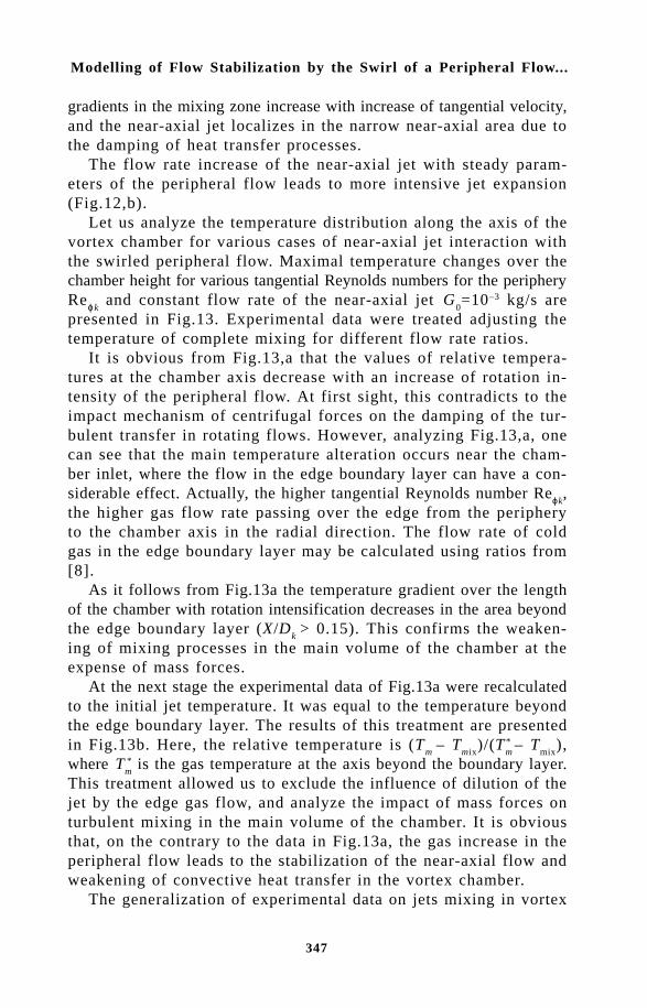
347
Modelling of Flow Stabilization by the Swirl of a Peripheral Flow...
gradients in the mixing zone increase with increase of tangential velocity,and the near-axial jet localizes in the narrow near-axial area due tothe damping of heat transfer processes.
The flow rate increase of the near-axial jet with steady param-eters of the peripheral flow leads to more intensive jet expansion(Fig.12,b).
Let us analyze the temperature distribution along the axis of thevortex chamber for various cases of near-axial jet interaction withthe swirled peripheral flow. Maximal temperature changes over thechamber height for various tangential Reynolds numbers for the peripheryReϕk
and constant flow rate of the near-axial jet G0=10–3 kg/s are
presented in Fig.13. Experimental data were treated adjusting thetemperature of complete mixing for different flow rate ratios.
It is obvious from Fig.13,a that the values of relative tempera-tures at the chamber axis decrease with an increase of rotation in-tensity of the peripheral flow. At first sight, this contradicts to theimpact mechanism of centrifugal forces on the damping of the tur-bulent transfer in rotating flows. However, analyzing Fig.13,a, onecan see that the main temperature alteration occurs near the cham-ber inlet, where the flow in the edge boundary layer can have a con-siderable effect. Actually, the higher tangential Reynolds number Reϕk
,the higher gas flow rate passing over the edge from the peripheryto the chamber axis in the radial direction. The flow rate of coldgas in the edge boundary layer may be calculated using ratios from[8].
As it follows from Fig.13a the temperature gradient over the lengthof the chamber with rotation intensification decreases in the area beyondthe edge boundary layer (X/D
k > 0.15). This confirms the weaken-
ing of mixing processes in the main volume of the chamber at theexpense of mass forces.
At the next stage the experimental data of Fig.13a were recalculatedto the initial jet temperature. It was equal to the temperature beyondthe edge boundary layer. The results of this treatment are presentedin Fig.13b. Here, the relative temperature is (T
m – T
mix)/(T
m* – T
mix),
where Tm* is the gas temperature at the axis beyond the boundary layer.
This treatment allowed us to exclude the influence of dilution of thejet by the edge gas flow, and analyze the impact of mass forces onturbulent mixing in the main volume of the chamber. It is obviousthat, on the contrary to the data in Fig.13a, the gas increase in theperipheral flow leads to the stabilization of the near-axial flow andweakening of convective heat transfer in the vortex chamber.
The generalization of experimental data on jets mixing in vortex

348
Thermal Plasma Torches and Technologies
Fig. 13. Maximal temperature alteration over the chamber height.
chambers was performed with the use of various criteria. One of thewidely used generalizing criteria is the integral parameter:
K I R M W r dr R R WV r drk k x
r
k k x
R
R
k s
k
= = ⋅∫ ∫−
0 02
0
22 20
πρ π ϕ , (4)
representing the ratio of the impulse flux of the near-axial jet to themoment of momentum flux of the peripheral stabilizing flow [4].Calculating parameter K according to the conditions at the chamberinlet, we will obtain:
KW F
W V F
G W
G Vinx
k xk k k
x
k k
= =ρ
ρ ϕ ϕ
0 02
0 0 0 . (5)

349
Modelling of Flow Stabilization by the Swirl of a Peripheral Flow...
Experimental data on the heat parameter of the jet, calculated witha use of parameter K
in, are presented in Fig.14. There one can see
the data for different flow rate ratios and for the constant diameterof the exhaust orifice, whose boundary is marked by the dotted linein the figure. It is obvious that in this form the experimental resultscan be easily generalized. Moreover, with the jet heat size approximatelyequal to the exhaust diameter, the jet stabilization occurs, when parameterK
in < 0.3. This corresponds to the results of [23]. The experimen-
tal results of this work demonstrate that the regime of the minimaljet mixing with the peripheral swirled flow in a non-diaphragm channeloccurs, when parameter K is in the range 0.6 ≥ K
in ≥ 0.15.
The experimentally determined critical value of the swirl parameterK
in ≤ 0.3, when stabilization of the near-axial jet is achieved, is proved
by calculation analysis of [9]. When mixing highly non-isothermalor density heterogeneous flows, the ratio of tangential velocity at theboundary of the near-axial jet to the longitudinal velocity compo-nent Vϕm
/Wx0
was the most suitable stabilization parameter. This isconfirmed by the correlation of experimental and calculation data onthe maximum expansion of the plasma jet in the vortex chamber, presentedin Fig.15. The jet stabilization is obtained there at Vϕm
/ Wx0
≥ 1.According to [17], this regime under isothermal conditions is achievedat Vϕm
/Wx0
≥ 5. This manifests a significant influence of jet heat-ing on the damping process of turbulence mixing in the swirl flow.
The current work was fulfilled with a partial financial support of theRussian Fund of Fundamental Investigations (grant No. 96-02-19122).
Fig. 14. Heat boundary of a jet in a vortex chamber.

350
Thermal Plasma Torches and Technologies
Referenes1. M.F. Zhukov, et al., Electric Arc Generators with Interelectrode Insertions
//Novosibirsk:Nauka. - 1981. (in Russian).2. E.P. Volchkov, G.R. Baldinov, V.I. Terekhov, Yu.N Tkach. Experimental
Investigation of Jet Stabilization in Near - Axis Region Plasma Re-actor” Contrib. Plasma Physics, 1988, v. 28, No. 1, p. 27-39.
3. A.I. Leontiev, E.P. Volchkov, V.P. Lebedev, et al., Heat Protection ofPlasmatron Walls // No-vosibirsk: Institute of Thermophysics SB RAS.-1995. - 336 p. (in Russian).
4. A.K. Gupta, D.G. Lilley, and N. Syred, Swirl Flows // Abacus Press-1984. - 588 p.
5. Chigier N., Beer J., Gregov D., Bassindale K. Jet Flames in Rotat-ing Flow Fields // Combustion and Flame. - 1970, v. 14, p. 171-179.
6. Syred N., Beer J. Combustion in Swirling Flows: A review // Combustionand Flame, 1974, v. 23, No. 2, p. 143-202.
7. I.V. Barmin, B.I. Katorgin, and V.I. Solonin, Concentration Fields ofHeterogeneous Gases in a Vortex Chamber // Proceedings of MoscowHigh Technical College. - 1971. - No. 144. - P. 77-80. (in Russian).
8. S.S. Kutateladze, E.P. Volchkov, and V.I. Terekhov, Aerodynamics andHeat and Mass Transfer in Limited Swirl Flows // Novosibirsk. - In-stitute of Thermophysics. - 1987. - 287 P. (in Rus-sian).
9. G.R. Baldinov, E.P. Volchkov, N.A. Dvornikov, Ma Tun Tce, and V.I.Terekhov, Gas-Swirl Stabilization of a Jet in Near-Axial Area of PlasmaReactor // J. of Engineering Physics. - 1993. - Vol. 64. - P. 131-140.(in Russian).
10. J. Beer, N. Chigier, T. Davis, K. Bassindale. Laminarization of TurbulentFlames in Rotating Environments // Combustion and Flame, 1971, v16,No. 1, p. 39-45.
11. E.P. Volchkov, S.Yu. Spotar, and V.I. Terekhov, Swirled Near-Wall Jetin a Cylindrical Channel // Preprint. - Institute of Thermophysics SBof USSR Academy of Sciences. - Novosibirsk. - 1982. - 42 p. (in Russian).
12. Yu.B. Kolesnikov and E.P. Sukhovich, Experimental Study of Turbu-lent Characteristics in Axis-Symmetrical Swirled Flow // Izvestiya [Acad.
Fig. 15. Expansion regularity of the near-axial plasma jet, T0
= 5500 K.
351
Modelling of Flow Stabilization by the Swirl of a Peripheral Flow...
of Sciences of Latvian SSR], Series of Phys. and Appl. Sciences. -1983. - No. 4. - P. 72-78. (in Russian).
13. V.K. Tchukin, Heat Transfer and Hydrodynamics of Internal Flows inFields of Mass Forces. - Moscow. - Mashinostroenie. - 1980. (in Russian).
14. E.P. Sukhovich, Experimental Study of Jet Mixing in a Limited SwirledFlow // Izvestiya [Acad. of Sciences of Latvian SSR], Series of Phys.and Appl. Sciences. - 1975. - No. 2. - P. 57-63. (in Russian).
15. B.P. Ustimenko, Processes of Turbulent Transfer in Rotating Flows /Alma-Ata. - 1978. (in Russian).
16. E.P. Volchkov, G.R. Baldinov, V.I. Terekhov, and Yu.N. Tkach, Investigationof Development Regularities of a Jet in Swirled Gas Flow // in: Generationof Electric Arc Plasma Flows. - No-vosibirsk. - 1987. - P. 184-199.
17. E.P. Volchkov, V.I. Terekhov, and Yu.N. Tkach, Experimental Study ofthe Mixing of Near Axial Jet with Peripheral Flow in Vortex Chamber.- Preprint./ Institute of Thermophysics of SB Acad. of Sceinces of USSR,No. 124-85. - 1985. - 42 p. (in Russian).
18. V.P. Lebedev and N.E. Shishkin, Influence of a Thickness of an OutletRim of Tangential Slit on the Efficiency of a Swirled Film Cooling //in: Near-Wall Jet Flows. - Novosibirsk. - 1984. - P. 14-20. (in Rus-sian).
19. E.P. Volchkov, V.P. Lebedev, and N.E. Shishkin, Experimental Studyof Gas Film Cooling in a Tube // Izvestiya [Acad. of Sciences USSR],Technical Sciences. - 1983. - Vol. 1. - No. 3. - P. 25-99. (in Russian).
20. E.P. Volchkov, N.A. Dvornikov, and V.I. Terekhov, To Calculation of theSwirled Gas Film Cooling in a Cylindrical Channel // J. of Appl. Mech.and Theor. Phys. - 1986. - No. 5. - P. 59-68. (in Russian).
21. E.P. Volchkov, V.P. Lebedev, and N.E. Shishkin, The Efficiency of SwirledGas Film Cooling on Adiabatic Surface // Swirl Effect and Its Use inTechniques. Proceedings of the 2 All Union Scientific Conference. -Kuibyshev. - 1976. - P. 217-220. (in Russian).
22. S.C. Kacker, L.M. Whitelaw. An Experimental Investigation of the Influenceof Slot-lip-thickness on the imperious-wall Effectiveness of the Uni-form-density. Two-dimensional Wall Jet // Int. J. Heat and Mass Transfer,1969, vol. 12, ¹ 9. - p. 1196-1201.
23. R.P. Lyane and Yu.V. Ivanov, Development and Mixing of Co-Axial Jetin Axial-Symmetrical Swirled Flow // Izvestiya [Acad. of Sciences ofLatvian SSR], Physics, Mathematics. - 1971. - Vol. 20. - ¹ 1. - P.58-65. (in Russian).

352
Thermal Plasma Torches and Technologies
L.I. Kuznetsov and V.N. YaryginInstitute of Thermophysics, Siberian Branch of Russian Academy of Sciences, Novosibirsk,Russia
!Experimental studies of the gas-dynamic structure of low-density jetsbeyond a sonic nozzle at high pressure drops [1–3] have shown thatin a wide range of parameters, including modes of rarefied flows, thegeometrical configuration of the jet and the distributions of the densityand total pressure are self-similar when the value of the complex
Re Re*L N= is constant. In this expression N p p= ∞0 is the ratio of
the stagnation pressure p0
to the pressure in ambient space pµ.
When a gas escapes into a medium with a temperature differentfrom the stagnation temperature of the gas of the jet, the distributionof the parameters in the mixing zone depends on the temperature dropand on the temperature levels. In this connection, it is possible for thetemperature factor to affect the structure of the jet as a whole, es-pecially at small values of Re⊥ that correspond to the transition to therarefied flow. The authors do not know of any analysis of these questions.It should be noted that no systematic studies of the gas-dynamic structureof rarefied high-temperature jets have been performed at all. At presentthere are only single papers [4,5] containing data on the measurementof the total pressure and density in individual modes of flow, and studiesof the physical processes in gas streams expanding from a plasma sourcehave been conducted without the necessary attention to the gas-dynamic structure of the jets [6–8].
In the present paper, we describe the results of a study of the densitydistribution in jets beyond a sonic nozzle and analyse the effect of thetemperature factor on the structure of the jets in the transition from

353
Low-density Plasma Jets: Production and Investigation
the mode of continuous flow to the scattering mode. In order to ex-clude from consideration the effects leading to a change in the physico-chemical properties of the gas at high temperatures (chemical reac-tions, dissociation, excitation of internal degrees of freedom with a markedchange in the ratio of heat capacities) the study was conducted at relativelylow temperatures on a monatomic gas, i.e. argon.
At T < 16000 K, the excitation of electron levels can be neglected,since under these conditions separations of the outer electrons (ioni-sation) occurs preferably [9]. Under typical conditions with the use ofplasma heaters the degree of ionisation is small as a rule and does notexceed 1% [5]. The recombination coefficient is of the order of10–10 – 10–12 cm3/s [10,11] and the relaxation rate is low [12]. Thisgives the reason to assume that the ionisation in the jet is practically“frozen-in” and, consequently, the adiabatic index along a streamlinecorresponds to a monatomic gas.
" # $%& & '&( %)#& #(#%$The measurements were carried out in a vacuum chamber [13] equippedwith an electron gun, an X-ray registration system and an arc heater(Fig.1). A three-electrode gun (5) generates a beam (12) whose energyis up to 30 keV and the current is up to 50 mA. The accelerating voltagein these measurements was 20 kV (except those where the electronenergy was varied), and the beam current ranged from 1 to 3 mA asa rule. For the beam to enter the working chamber, a two-chambersystem of differential pumping (6) was used, which generates a workingpressure in the thermal cathode area of about 10–3 Pa under a pressurein the working chamber p
µ up to 100 Pa.
The electron beam passed through the vacuum chamber and arrivedat an aluminium collector (13) with an entrance window 14 mm indiameter. The electron beam current was measured by a milliammeter(14) included in the collector circuit.
The X-rays were detected with a proportional counter, operated withan argon–methane detector gas (10). The location of the measurementswas determined by the diameter of the electron beam and by the widthof a collimator slit (9). The collimator was positioned in front of theentrance window of the counter. The spatial resolution was about 2mm in all planes.
The signal from the counter comes to a recording device comprisingan amplifier, a discriminator, an electronic counter, and an integrator.
The arc heater was used as a gas-dynamic source. It was mountedon a three-component mechanically driven traverse. The design of thearc heater is shown in Fig.2. The arc heater is of the single-

354
Thermal Plasma Torches and Technologies
chamber design with vortex stabilisation of the arc. It consists of threemain units: cathode (1, 2), anode (3, 4), and stagnation chamber witha replaceable sonic nozzle (5) with diameter d = 1–5 mm. The workinggas can neutral gases (argon, helium, nitrogen) or oxygen containinggases (CO
2, air). In the first case, the cathode (2) is made of tung-
sten and in the second case a zirconium cathode is used. The arc heatersteadily works in the range of the mass flow rate of the gas, G = 0.15-1.5 g/s, stagnation pressure, 5×10⁴ – 5×10⁵ Pa and provides equilib-rium heating of the gas up to temperature T
0 = 10000 K. Tempera-
ture was determined from the energy balance of the method of the equi-librium sound speed [14]. Peculiarities of work at lowered pressure andthe methods of accounting for the modes of operations are presentedin more detail in [14].
* %%!+%&$ '&($%,Today, the electron beam is one of the main methods for investigationof rarefied gas flows allowing us to determine a series of local parameters[15]. The main idea of the active electron-beam method is to determinegas parameters based on the radiation spectrum excited by a fast electronbeam. The above-mentioned spectrum covers the range from the X-ray region to the visible one. The relation between the intensities excitedby electron beam spectra and local gas parameters are provided eithertheoretically or by a calibration curve.
The electron-beam technique is characterised by a good spatial localisationin combination with small disturbances in the region under consideration.Ultraviolet and visible beam-induced radiation is most generally em-ployed for diagnostics [13,16,17]. However, the application of these tech-
Fig.1 Density measurement circuit. 1 – rough vacuum pump, 2, 3 – diffusion pumps,4, 7 – electromagnetic lens, 5 – electron gun, 6 – system of differential pumping, 8 –deviative lens, 9 – X-ray collimator, 10 – X-ray detector, 11 – vacuum chamber,12 – electron beam, 13 – collector cup, 14 – milliammeter, 15 – arc heater.Fig.2 (right) Arc heater. 1, 2 – cathode, 3, 4 – anode, 5 – stagnation chamber with areplaceable sonic nozzle.

355
Low-density Plasma Jets: Production and Investigation
niques for the investigation of high-temperature gas flows is associ-ated with difficulties. One of them arises when the temperature of gasunder study increases by up to several thousand degrees. In this case,there appears underground gas radiation in the optical region that masksthe electron-beam-induced radiation. The use of the X-ray spectrumregion [18-20] is most appropriate for overcoming the above difficultiesand allowed the capabilities of electron-beam diagnostics of rarefiedgas and plasma to be increased.
These methods are based on the interaction of fast beam electrons(with energies amounting to several tens of keV) with the Coulombfield of the atom nucleus [18] or with electrons in the outer shells [20],which generates respectively the bremsstrahlung or characteristicX-ray radiation, the intensity of which is proportional to the concen-tration of atoms of the investigated gas.
The concept of the density measurement by the bremsstrahlung wassuggested in [18,19] and developed in [20,21]. The integral intensityof X-ray radiation, I, of the gaseous target is directly proportional tothe density number of the gas and is expressed as follows:
I cinZV V
Vid=
−2 (1)
Here c is the coefficient depending on the interaction cross-sectionand detector aperture, V is the acceleration voltage of the electron beam,V
d is the threshold of registering by the detector of γ-quanta in the
region of soft X-ray radiation, Z is the atomic number, n is the atomconcentration, i is the electron beam current.
The integral pulse numbers of γ-quanta, Nj, registered by the X-ray
detector is expressed as follows:
N c inZV V
Vid= '
ln( / )2 (2)
The characteristic X-ray radiation intensity obtained with the useof the Tompson model for the determination of the ionisation cross-section of internal atom shells [20] is expressed by
I BinV V
VNj
jj=
−( )~
2 (3)
where Vj is the potential of j-shell ionisation, B is the parameter depending
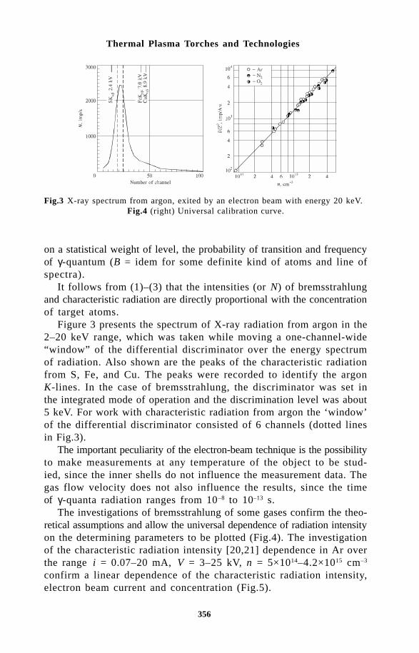
356
Thermal Plasma Torches and Technologies
on a statistical weight of level, the probability of transition and frequencyof γ-quantum (B = idem for some definite kind of atoms and line ofspectra).
It follows from (1)–(3) that the intensities (or N) of bremsstrahlungand characteristic radiation are directly proportional with the concentrationof target atoms.
Figure 3 presents the spectrum of X-ray radiation from argon in the2–20 keV range, which was taken while moving a one-channel-wide“window” of the differential discriminator over the energy spectrumof radiation. Also shown are the peaks of the characteristic radiationfrom S, Fe, and Cu. The peaks were recorded to identify the argonK-lines. In the case of bremsstrahlung, the discriminator was set inthe integrated mode of operation and the discrimination level was about5 keV. For work with characteristic radiation from argon the ‘window’of the differential discriminator consisted of 6 channels (dotted linesin Fig.3).
The important peculiarity of the electron-beam technique is the possibilityto make measurements at any temperature of the object to be stud-ied, since the inner shells do not influence the measurement data. Thegas flow velocity does not also influence the results, since the timeof γ-quanta radiation ranges from 10–8 to 10–13 s.
The investigations of bremsstrahlung of some gases confirm the theo-retical assumptions and allow the universal dependence of radiation intensityon the determining parameters to be plotted (Fig.4). The investigationof the characteristic radiation intensity [20,21] dependence in Ar overthe range i = 0.07–20 mA, V = 3–25 kV, n = 5×10¹⁴–4.2×1015 cm–3
confirm a linear dependence of the characteristic radiation intensity,electron beam current and concentration (Fig.5).
Fig.3 X-ray spectrum from argon, exited by an electron beam with energy 20 keV.Fig.4 (right) Universal calibration curve.

357
Low-density Plasma Jets: Production and Investigation
Fig.5 Calibration curve for characteristic radiation intensity.Fig. 6 (right) Beam cross-section.
The estimates show that the radiation absorption between the de-tector and the electron beam, as well as the effect of fluorescent radiationand disturbances created by the electron beam in the gas do not in-fluence significantly the accuracy of measurements in the X-rayregion. The upper limit of the method with respect to atom concen-tration is determined mainly by electron beam scattering in the medium.The lower limit is determined by the apparatus sensitivity, detector apertureand beam current. Thus for A n
max is about 3×l015 cm–3 with V =
20 kV and 10 cm beam length, and nmin
is about 3×1012 cm–3 with i=1 mA, a spatial resolution of about 1 mm–3, the relative solid angle ofthe detector of 10–5, and the signal integration time less or, approxi-mately, equal 10 s.
It should be noted that the measurement technique for the local gasdensity developed by characteristic radiation increases the possibilitiesof electron-beam diagnostics, since it allows measurements of partialdensities in multicomponent gas mixtures and to make investigationsin the vicinity of walls.
Fig.7 Axial profiles of density for ReL = 100.

358
Thermal Plasma Torches and Technologies
Besides it was established by special measurements that the use ofX-ray region leads to a better spatial localisation of measurements. Atypical beam size determined by the radiation intensity in X-ray regionis much less than that measured in an optic region under the same conditionsof beam formation (Fig.7). The matter is that the secondary electronsdo not effect the radiation excitation in the X-ray spectrum region, sincetheir energy level does not exceed tens electron-volt. These data wereobtained by using electric gages [22].
- )&#(&$! # ! %. /%#( &#$&%#The principal operating parameters (see Table) were varied in the followingranges: T
0 =290–5200 K, d = 1.1–5 mm; G = 0.003–1.4 g/s; Re
*=300-
40000; N = 300–30000. The temperature of ambient gas T∞ is 290 K.The given measurement results of density in ρN x N− / or
ρN y N− / coordinates are shown in Figures 8–13, whereρ ρ ρ= =/ /0 0n n is the ratio of density to that in the stagnation chamber,x x d y y d x= =/ , / , is the distance along jet axis from nozzle, y is thedistance from the jet axis.
The possibility of generalising the data on the density distribution
in the jet at fixed values of ReL and T T0 / ∞ in a wide range of val-
ues of ReL
>100 and N > 100 is shown, first of all, on the basis of theexperiments.
As an example, the results of measurements of the axial densitydistribution are presented in generalised form in Fig.7 (for Re
L =100),
Fig. 8 Cross-section of density for ReL = 100.
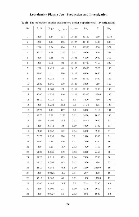
359
Low-density Plasma Jets: Production and Investigation
Table The operation modes parameters under experimental investigations
No T0, K G, g/s p
???,
µ tord, mm Re
*N Re
L
1 290 1.14 534 2,125 40100 550 1010
2 290 1.14 185 2.125 40100 4480 600
3 290 0.74 104 5.0 10900 866 371
4 1510 1.39 1260 3.11 9900 860 341
5 290 0.68 85 3.135 6100 2080 312
6 290 0.56 08 2.125 19700 4150 307
7 290 0.423 41 3.115 10000 3520 168
8 2000 1.1 590 3.115 6600 1650 162
9 290 0.236 71 1.10 15750 9400 162
10 2030 0.666 970 3.135 3950 610 160
11 290 0.389 23 2.110 30100 9200 105
12 1500 1.030 146 2.116 10900 10800 105
13 1510 0.729 223 5.0 3220 950 105
14 290 0.222 30.8 5.0 31.30 925 103
15 2970 1.13 407 5.0 3360 1110 101
16 4970 0.92 1290 3.11 3180 1010 100
17 290 0.196 20.6 2.12 68.40 7050 81
18 290 0.118 34 1.10 7900 9400 81
19 3840 0.857 572 2.14 5000 3900 81
20 5170 0.898 920 3.21 2910 1300 81
21 5060 0.85 926 3.11 2890 1300 80
22 290 0.20 18.7 2.12 7020 7750 80
23 2000 0.666 239 3.13 3970 2460 80
24 2020 0.913 179 2.14 7900 9700 80
25 4910 0.295 413 3.12 1030 996 33
26 1510 0.156 83.8 1.10 3160 28500 19
27 290 0.0125 11.6 3.11 297 370 16
28 4710 0.302 41 3.11 1090 10000 11
29 4700 0.148 24.8 5.0 331 3230 5.6
30 290 0.005 2.7 1.10 332 5050 4.7
31 290 0.0027 1.9 2.12 100 1040 3.2
p∞, µtor

360
Thermal Plasma Torches and Technologies
while transverse density profiles in three different cross sections ofthe jet are presented in Fig.8 (the conditions are denoted by the cor-responding mode number in Table ). As is seen, the data are well generalisedfor fixed values of Re
L and T
0. Similar generalisation also occurs for
other values of ReL
(in the range ReL=50–1000). On the basis of the
data obtained it can be concluded that in the indicated range of ReL
the density distribution along the length of the jets studied is self-similarwith respect to N when the values of T
0 and Re
L are fixed. This is
in agreement with the conclusions made on the basis of a study of nitrogenjets at T
0 =T∞=300 K [3].
The next stage of the studies was the analysis of the effect of thetemperature factor on the structure of low-density jets. The analysisof the experimental data is considerably simplified by the self-similaritywith respect to N in the density distribution in the jets which was establishedabove. The results of measurements of the axial density distributionswith a fixed value Re
L = 80 and different T
0 = 290–5200 K are pre-
sented in Fig.9. As seen from the graph, agreement of the axial densitydistributions for different T
0 is observed in the first cycle of the jet.
In the region behind the Mach disk the temperature factor begins toaffect the axial density distribution and the experimental data becomestratified. With an increase in the value of Re
L the region in which the
temperature factor has no effect spreads down-stream, and whenRe
L = 150 generalisation of the experimental data with respect to the
axial density distributions at different values of T0 (T
0 = 290–2000 K)
is observed in the entire length of the jets studied x N/ ≤ 3 With adecrease in Re
L (Re
L < 80) the temperature factor already begins to
affect the axial density distributions in the region of the initial sectionof the jet (the first cycle).
Transverse density profiles in the cross section x N/ =0.44 with
Fig.9 Axial profiles of density for ReL =80 and different stagnation gas temperature.
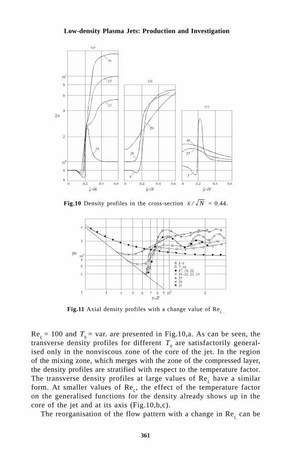
361
Low-density Plasma Jets: Production and Investigation
Fig.10 Density profiles in the cross-section x N/ = 0.44.
ReL
= 100 and T0
= var. are presented in Fig.10,a. As can be seen, thetransverse density profiles for different T
0 are satisfactorily general-
ised only in the nonviscous zone of the core of the jet. In the regionof the mixing zone, which merges with the zone of the compressed layer,the density profiles are stratified with respect to the temperature factor.The transverse density profiles at large values of Re
L have a similar
form. At smaller values of ReL, the effect of the temperature factor
on the generalised functions for the density already shows up in thecore of the jet and at its axis (Fig.10,b,c).
The reorganisation of the flow pattern with a change in ReL can be
Fig.11 Axial density profiles with a change value of ReL .
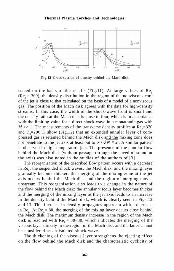
362
Thermal Plasma Torches and Technologies
traced on the basis of the results (Fig.11). At large values of ReL
(ReL
= 300), the density distribution in the region of the nonviscous coreof the jet is close to that calculated on the basis of a model of a nonviscousgas. The position of the Mach disk agrees with the data for high-densitystreams. In this case, the width of the shock-wave front is small andthe density ratio at the Mach disk is close to four, which is in accordancewith the limiting value for a direct shock wave in a monatomic gas withM >> 1. The measurements of the transverse density profiles at Re
L=370
and T0=290 K show (Fig.12) that an extended annular layer of com-
pressed gas is retained behind the Mach disk and the mixing zone doesnot penetrate to the jet axis at least out to x N/ = 2 . A similar patternis observed in high-temperature jets. The presence of the annular flowbehind the Mach disk (without passage through the speed of sound atthe axis) was also noted in the studies of the authors of [3].
The reorganisation of the described flow pattern occurs with a decreasein Re
L, the suspended shock waves, the Mach disk, and the mixing layer
gradually become thicker; the merging of the mixing zone at the jetaxis occurs behind the Mach disk and the region of merging movesupstream. This reorganisation also leads to a change in the nature ofthe flow behind the Mach disk: the annular viscous layer becomes thickerand the merging of the mixing layer at the jet axis leads to an increasein the density behind the Mach disk, which is clearly seen in Figs.12and 13. This increase in density propagates upstream with a decreasein Re
L. At Re
L= 80, the merging of the mixing layer occurs close behind
the Mach disk. The maximum density increase in the region of the Machdisk is reached with Re
L = 30–80, which indicates the merging of the
viscous layer directly in the region of the Mach disk and the latter cannotbe considered as an isolated shock wave.
The thickening of the viscous layer strengthens the ejecting effecton the flow behind the Mach disk and the characteristic cyclicity of
Fig.12 Cross-section of density behind the Mach disk.

363
Low-density Plasma Jets: Production and Investigation
the flow (‘barrels’) appears. Such cyclicity is well seen, for example,in Fig.12 at Re
L = 80. With a further decrease in Re
L , the density of
shock waves degenerate, the flow becomes almost fully viscous (themerging of the viscous layer already occurs near the nozzle cut), andat Re
L =10 the transition to the so-called scattering mode is observed.
The rise in density at ReL
=10 and T0/T∝ >>1 is due to cooling of the
gas in the mixing zone.The qualitative changes in the structure of a jet of the monatomic
gas beyond the sonic nozzle with variation in the rarefaction and thetemperature factor have been clarified as a result of the experimentsand generalisations performed. The quantitative data obtained on thedensity distribution can be used for comparison with calculation in thedevelopment of a model of a jet.
References1 V.S.Avduevskii, et al, Effect of viscosity on the flow in the initial sec-
tion of a strongly underexpanded jet, Bulletin of the Academy of Sci-ences of the USSR, No.1 (1971).
2 N.I.Kislyakov, A.K.Rebrov, and R.G.Sharafutdinov, J. of Applied Mechanicsand Technical Physics, No.1 (1973).
3 V.V.Volchkov, et al, J. of Applied Mechanics and Technical Physics, No.2 (1973).
4 N.I.Yushchenkova, S.A.Lyzhnikova, and V.I.Nemchenko, In: The structureof supersonic jets of gas and low-temperature plasma. Transfer Ef-fects in a Low-Temperature Plasma (in Russian), Nauka i Tekhnika,Minsk (1969).
5 R.B.Fraser, F.Robbin and S.Talbot, Phys. Fluids, 14 2317 (1971).6 M.Sinclair, A.A.Sonin, and J.H.de Leeuw, Phys. Fluids, 10, No.4 (1967).7 G.A.Luk’yanov and G.V.Petukhov, High Temperature, 7, No.5 (1969).8 V.M.Gol’dfarb and I.E.Kostygova, In: Optical study of a supersonic ni-
trogen jet. Study of Low-temperature Plasma Sources [in Russian], Vol.466, Izd. LGPI, Leningrad (1971).
9 E.Resler, S.-C.Lin, and A.Kantrowitz, J. Appl. Phys., 23, 1390 (1952).1 0 W.A.Clayden, Langmuir probe measurements in the R.A.R.D.E. plasma
jet, in: Rarefied Gas Dynamics. Proc. of 3rd International Symposium,Vol.2, Academic Press (1963).
11 V.M.Gol’dfarb, et al, J. of Applied Mechanics and Technical Physics,No.1 (1967).
1 2 R.H.Kirchhoff and L.Talbot, AIAA J., 9, No.6, 1098 (1971).1 3 L.I.Kuznetsov and V.N.Yarygin, In: X-ray bremsstrahlung of gas targetsand
its use for measuring the local density of a gas. Apparatus and Methodsof X-Ray Analysis, Mashinostroenie, Leningrad, 11 (1972).
1 4 S.S.Kutateladze and V.N. Yarygin: Academician S.S. Kutateladze, Se-lected Papers (in Russian), Novosibirsk, Nauka, (1989) 246.
1 5 L.A.Gochberg, AIAA Paper, 94-2635: 43 (1994).1 6 E.P.Muntz and D.J.Mardsen, In: Electron Excitation Applied to the Ex-
perimental Investigation of Rarefied Gas Flows. Rarefied Gas Dynamics,Acad. Press, N-Y-L, 2:495 (1963).

364
Thermal Plasma Torches and Technologies
1 7 A.A.Bochkarev, et al, In: Measurement of Gas Flow Parameters Usingan Electron Beam, Experimental Methods in Rarefied Gas Dynamics(in Russian), Inst. of Thermophysics, Novosibirsk (1974).
1 8 C.A.Ziegler, et al, RSI, 35:450 (1964).1 9 A.N.Trohan, J. of Applied Mechanics and Technical Physics, No.3 (1964).2 0 L.I.Kuznetsov, A.K.Rebrov, and V.N.Yarygin, Diagnostics of Ionized Gas
by Electron Beam in X-ray Spectrum Range, Proc. of 11th Intern. Conf.on Phenomena in Ionized Gases, Prague (1973).
2 1 N.G.Zharkova, et al, High Temperature, No.1 (1976).2 2 L.I.Kuznetsov, et al, In: Investigation of Diagnostic Electron Beam Plasma.
Diagnostic of Rarefied Gas Flows (in Russian), Inst. of Thermophysics,Novosibirsk (1979).

3 6 5
Effect of Arc Current Modulation on Thermal Plasma Flow
Farih A. Salyanov
In this paper, the theoretical investigation of the effect of arc currentmodulation on the thermal plasma flow in plasma torches is described.The basis of the nonstationary mathematical model is a set of differentialequations of energy, mass and momentum conservation, and the integralform of Ohm’s law. Unlike the previous well-known nonstationary theories,this boundary value problem takes into account axial acceleration of theplasma flow, radius variability of the arc column and arbitrary law of thealternating component of arc current in plasma torches.
As follows from the general solution of this problem, modulation ofarc current leads to the existence of the longitudinal waves of tempera-ture and electric conductivity of the plasma, electric field strength andother parameters of the thermal plasma flow. The influence of modula-tion of the parameters on the processes in plasma torches and plasma flowis studied in detail.
!"
Investigations of the thermal plasma flows and processes in plasmatorches are of considerable interest due to a wide range of applicationsof high-heat flows. At the present time, plasma techniques can beused in the treatment of materials, in metallurgy and energetics, plasmaspraying, plasma chemistry and other new branches of plasma technology.
The possibility of theoretical studies of the processes in arcs stabilizedin a tube was shown for the first time in the classic paper of H. Mekker[1]. By now, the basic phenomena and processes in arc plasma torcheshave been well investigated, the basis of their theories and basis ofthe theory of thermal plasma flows have been created. The funda-mental results of the thermal plasma problems and technologies were
Institute of Mechanical Engineering RAS 2/ 31 Lobachevsky Str., PO Box 99,Rus - 420503 Kazan,
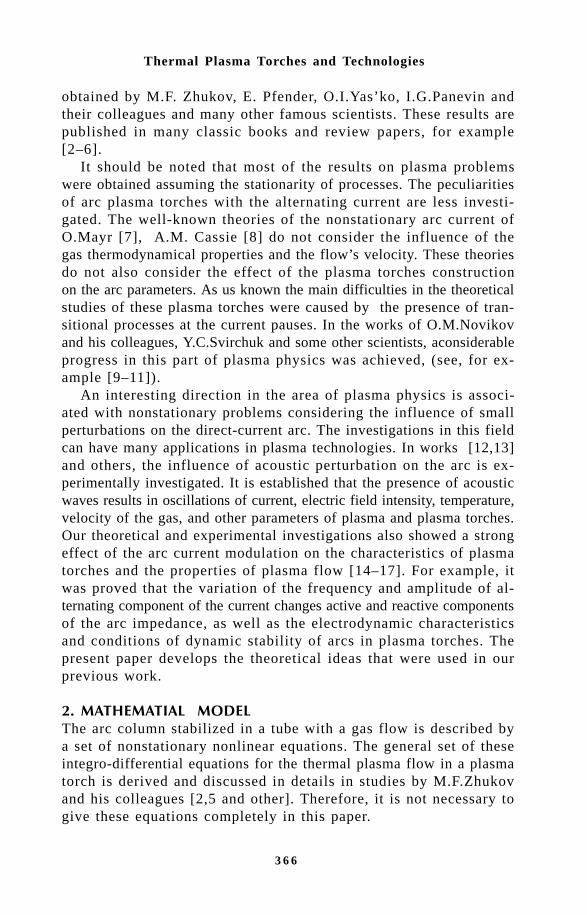
3 6 6
Thermal Plasma Torches and Technologies
obtained by M.F. Zhukov, E. Pfender, O.I.Yas’ko, I.G.Panevin andtheir colleagues and many other famous scientists. These results arepublished in many classic books and review papers, for example[2–6].
It should be noted that most of the results on plasma problemswere obtained assuming the stationarity of processes. The peculiaritiesof arc plasma torches with the alternating current are less investi-gated. The well-known theories of the nonstationary arc current ofO.Mayr [7], A.M. Cassie [8] do not consider the influence of thegas thermodynamical properties and the flow’s velocity. These theoriesdo not also consider the effect of the plasma torches constructionon the arc parameters. As us known the main difficulties in the theoreticalstudies of these plasma torches were caused by the presence of tran-sitional processes at the current pauses. In the works of O.M.Novikovand his colleagues, Y.C.Svirchuk and some other scientists, aconsiderableprogress in this part of plasma physics was achieved, (see, for ex-ample [9–11]).
An interesting direction in the area of plasma physics is associ-ated with nonstationary problems considering the influence of smallperturbations on the direct-current arc. The investigations in this fieldcan have many applications in plasma technologies. In works [12,13]and others, the influence of acoustic perturbation on the arc is ex-perimentally investigated. It is established that the presence of acousticwaves results in oscillations of current, electric field intensity, temperature,velocity of the gas, and other parameters of plasma and plasma torches.Our theoretical and experimental investigations also showed a strongeffect of the arc current modulation on the characteristics of plasmatorches and the properties of plasma flow [14–17]. For example, itwas proved that the variation of the frequency and amplitude of al-ternating component of the current changes active and reactive componentsof the arc impedance, as well as the electrodynamic characteristicsand conditions of dynamic stability of arcs in plasma torches. Thepresent paper develops the theoretical ideas that were used in ourprevious work.
# $ % !%
The arc column stabilized in a tube with a gas flow is described bya set of nonstationary nonlinear equations. The general set of theseintegro-differential equations for the thermal plasma flow in a plasmatorch is derived and discussed in details in studies by M.F.Zhukovand his colleagues [2,5 and other]. Therefore, it is not necessary togive these equations completely in this paper.

3 6 7
Effect of Arc Current Modulation on Thermal Plasma Flow
It is well-known that, at present, it is not possible to get the generalsolution of the general system of equations for the thermal plasmaflow in a plasma torch. However, having made a series of simplifyingassumptions, it is possible to compose some mathematical models forthe area of thermal plasma physics, and obtain the analytical solutionof their equations.
Analysing the phenomena in the thermal plasma flow and heat transferprocesses in a plasma torch, one can see that Joule’s dissipation, radialconduction heat transfer, axial convective heat transfer, and radia-tion flux play the basic role in the equation of energy conservation.These processes of heat transfer make the fundamental contributionin the balance of energy. The simplifying assumptions are physicallysubstantiated, discussed many times and used in the well-knowntheoretical studies, for example [2,5,14–17]. Thus, taking these as-sumptions into account, the processes of heat and mass transfer inthe area of the arc column can be described by the following com-bination of equations:
ρ ω ∂∂
ρυ ∂∂
∂∂
χ ∂∂
σ εW
t
W
l z R r rr
rE+ =
+ −1
22Τ
(2.1)
( )∂ ρ∂ ω
∂∂
ρ υt l z
+ =1
0 (2.2)
ρ ω ∂ υ∂
ρ υ ∂ υ∂
∂∂t l z
P
l z+ = − (2.3)
I z t R E z t r z t rdr( , ) ( , ) ( , , )= ∫2 2
0
π σξ
(2.4)
The following notation is used: r, z are the cylindrical coordinatesreferred to R and l, respectively; R, l are the channel radius and itslength; t is the time multiplied by ω; ρ, υ, χ, W, σ, ε, P, are density,the axial component of velocity, heat conduction, total energy perunit mass, electric conductivity, emissivity, and gas pressure; ω isthe frequency of oscillations; I is current; E is the electric field intensity;ξ = ξ1/R, ξ1 radius of the arc column.
It is seen that our mathematical model consists of gas dynamic

3 6 8
Thermal Plasma Torches and Technologies
and thermodynamic problems. First, let us consider the gas dynamicproblem.
3. THE GAS DYNAMIC PROBLEMIn accordance with the adopted mathematical model, the laminar gasflow under the plasma torch conditions can be described by the Eulerand continuity equations in the form:
( )∂ ρ∂ ω
∂∂
ρ υt l z
+ =10 (3.1)
ρ ω ∂ υ∂
ρ υ ∂ υ∂
∂∂t l z
P
l z+ = − (3.2)
Let us take advantage of the Rieman method [19] and assume that
υ υ ρ ρ= = =( ), ( ) , ( , )P P P P z t (3.3)
Taking into account expressions (3.3) allows one to write the setof equations (3.1) and (3.2) as
∂∂
υρ ∂ υ
∂
∂ω ∂
Pt
P
Pl z
+ +
=10
(3.4)
∂∂
υρ ∂ υ
∂∂ ρ∂
∂ω ∂
P
t
P
P
P
l z+ +
= 0 (3.5)
Equations (3.4)–(3. 5) will correlate under the indispensable conditionof

3 6 9
Effect of Arc Current Modulation on Thermal Plasma Flow
1
ρ ∂ υ∂
ρ ∂ υ∂
∂ ρ∂P
P
P
= (3.6)
ρ ∂ υ∂
∂ ρ∂P P
=
2
(3.7)
Thus, for the υ (P) function one obtains
∂ υ∂
∂ ρρ ∂P P
= ±2 (3.8)
( )υ ∂ ρρ ∂
PP
d P= ± ∫ 2 (3.9)
The thermodynamic processes in the arc column can be described bythe polytropic equation in the form
ρ = =−−
Α P nc c
c cn p
v, (3.10)
where n is the polytropic index, c the specific heat of the polytropicprocess, A = const.
It is well known from the classical thermodynamics that the equationof the polytropic process contains as its particular case the isothermalprocess (at n = 1) and the adiabatic process (at n = 1/γ, where γis the adiabatic constand).
By integrating the right part of equation (3. 9) and taking intoaccount expression (3.10), one obtains
( )υ Pn
A nP const
n
= ±−
+−2
1
1
2 . (3.11)
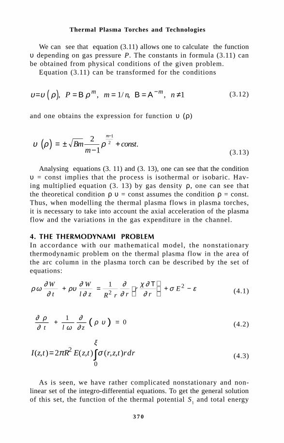
3 7 0
Thermal Plasma Torches and Technologies
We can see that equation (3.11) allows one to calculate the functionυ depending on gas pressure P. The constants in formula (3.11) canbe obtained from physical conditions of the given problem.
Equation (3.11) can be transformed for the conditions
( )υ υ ρ ρ= = = = ≠−, , / , ,P m n nm mΒ Β Α1 1 (3.12)
and one obtains the expression for function υ (ρ)
( )υ ρ ρ= ±−
+−
Bmm
constm2
1
1
2 . (3.13)
Analysing equations (3. 11) and (3. 13), one can see that the conditionυ = const implies that the process is isothermal or isobaric. Hav-ing multiplied equation (3. 13) by gas density ρ, one can see thatthe theoretical condition ρ υ = const assumes the condition ρ = const.Thus, when modelling the thermal plasma flows in plasma torches,it is necessary to take into account the axial acceleration of the plasmaflow and the variations in the gas expenditure in the channel.
& $$ !' %
In accordance with our mathematical model, the nonstationarythermodynamic problem on the thermal plasma flow in the area ofthe arc column in the plasma torch can be described by the set ofequations:
ρ ω ∂∂
ρυ ∂∂
∂∂
χ ∂∂
σ εW
t
W
l z R r rr
rE+ =
+ −1
22Τ
(4.1)
( )∂ ρ∂ ω
∂∂
ρ υt l z
+ =1
0 (4.2)
I z t R E z t r z t rdr( , ) ( , ) ( , , )= ∫2 2
0
π σξ
(4.3)
As is seen, we have rather complicated nonstationary and non-linear set of the integro-differential equations. To get the general solutionof this set, the function of the thermal potential S
1 and total energy
3 7 1
Effect of Arc Current Modulation on Thermal Plasma Flow
per unit volume N, can be introduced,where
S d T N Wo
T
1 = =∫ χ ρ, (4.4)
Let us assume the linear approximations of the functions N, σ, εdepending on the function S, where S = S
1 – S* is the value of the
function S1 at r = ξ .
In accordance with the adopted formulation of our thermal problem,the set of equations (4.1)–(4. 3) can be written as
∂∂
υω
∂∂
∂∂
∂∂
S
t l
S
z
a
r rr
S
rc E S b S+ =
+ −1
21 (4.5)
I z t R E z t S r z t r d rs( , ) ( , ) ( , , )= ∫2 2
0
π σξ
(4.6)
Here
a R N c a R c a R b cl zs s s= = = = +−( ) , , ,2 1
12
22
1 2ω σ ε ∂ υω ∂
We can solve equations (4.5) and (4.6) for arbitrary initial andboundary conditions in the form
S r t r t S r z r z S z tS
r r( , , ) ( , ) , ( , , ) ( , ), ( , , ) , | ,0 0 0 01 2 0= = = ==ϕ ϕ ξ∂∂
υ υ α α= = + ≥0 0 01 0( ) , ( ) ( ) , .z z k z k
It is seen that this nonstationary thermal problem takes into accountthe axial acceleration of the thermal plasma flow, variability of theexpenditure and compressibility of the gas, radius of the arc columnand the arc current in the channel of the plasma torch.
The nonlinear parabolic equation (4.5) with variable coefficientscan be solved by means of transition to the new independent coor-dinates,
(4.7)
3 7 2
Thermal Plasma Torches and Technologies
rr
x z tb k
a z bl1
0 00
02= = = − =
ξτ
υω
, , ( ) , . (4.8)
In this way, equation (4.5) can be rewritten as
bS
x tb
z
r S
r
a
r rr
S
rc E x S b x S
∂∂
∂ ξ∂
∂ ξ∂ ξ
∂∂ ξ
∂∂
∂∂
τ− +
=
+ −1
12
1 11
11
21( , ) ( ) (4.9)
One can obtain the general analytical solution of equation (4.9)under the indispensable condition
∂ ξ∂
∂ ξ∂
2 2
1 1tb
zk k c o n s t+
= =, . (4.10)
Then we have
bS
x
a
r rr
S
r
k r S
rc E S b Sξ
∂∂
∂∂
∂∂
∂∂
ξ ξ2
1 11
1
1 1
11
2 21
2
2=
+ + − (4.11)
We shall seek for the solution of the equation in the form
S r xc
b
E x
xd x U r x
x
( , , ) exp( , )
( )( , , )1
1
0
2
01τ
τα
τ=
∫ (4.12)
From formulas (4.11) and (4.12) we get a linear separable vari-
ables equation, with respect to the function U r x( , , )1 τ ,
bU
xb U
a
r rr
U
r
k r U
rξ
∂∂
ξ ∂∂
∂∂
∂∂
21
2
1 11
1
1 1
12+ =
+ (4.13)
Let us take advantage of the Fourier method
U r x X x V r( , , ) ( , ) ( )1 1τ τ= (4.14)

3 7 3
Effect of Arc Current Modulation on Thermal Plasma Flow
Now, from equation (4.13) we get the set of equations
d
d rr
d V
d r
k r
a
d V
d rr Vn
11
1
1 12
1
212
0
+ + =µ (4.15)
( )bx
X x b anξ ∂∂
τ ξ µ21
2 2ln ( , + =− (4.16)
The solution of equation (4.15) can be written in terms of degeneratedhypergeometrical functions,
V rr
nn( ) , ;1
212
14
= −
Φ
µβ
β (4.17)
where Φn (finite r = 0 ) are eigenfunctions of the equation describing
the arc column with the account of the molecular and convection heatand mass transfer,
Φ nn
n n n nm
n
r
m
m
r
µβ
β
µ µ β µ β µ ββ
β
212
2 2 2 2
21
12
14
12 1
4
, ;
( ) ( )...[ ( ) ]
( !);
−
=
= ++ + + −
−
=
∞∑
(4.18)
β = −k
ak11, is determined by formula (4.10).
The proper values µn of the functions may be obtained from the
equation
Φ nn rµ
ββ2
12
14
0, ; −
= (4.19)
The general properties of the functions Φ (µn,β,r
1) were described
in [20], where β = 0 the functions Φn transfers in the Bessel’s func-
tion J0 (λ n, r).
The solution of equation (4.16) is dependent on the form of thefunction ξ , which is determined by condition (4.10). In case of thestationary arc current with modulated alternating component we can

3 7 4
Thermal Plasma Torches and Technologies
assume that ξ = ξ (z). This ad hoc assumption leads to
ξ ξ202
01= + k z , ξ 02 1
0 0
2=
k
b kβ =
k
a1 β
ξ= 0
20 0
2
b k
a (4.19)
where ξ0 is the radius of the arc column at z= 0.Having taken into account these conditions, we can write the solution
of equation (4.16) as
X x fc x
b knn( , ) ( )exp
( ( ) )τ τ α α η= − −
−2 12
0 0
2 (4.20)
where
η µ ξξ
nn a b k
b k= +2
2
20 0 0
2
0 0 02
Thus, the solution of equation (4.11) may be presented in accordancewith the obtained expressions and formulas. Coming back to the initialcoordinates, we can represent the solution of equation (4.5) in theform
)(
S r z tc
b
E x
xd x
fc
b kz
r
z
nn
nnn
( , , ) exp( , )
( )
( ) exp ( ) , ; .
=
×
× × − −
× −
∫
∑=
∞−
1
0
2
0
2
0 01
22 2
2
21 1
4
τα
τ α αµβ
βξ
η Φ (4.21)
The functions ( )fn τ , f f tb k
k zn n( )τ = − +
21
0 00 , may be ob-
tained from (4.21) and initial and boundary conditions (4.7). Thus,we have
f A atn n( ) ( ),τ τ τ= >0 (4.22)
3 7 5
Effect of Arc Current Modulation on Thermal Plasma Flow
f
B Yb k
tb k
k z
n
n
n
n( )
( ) ( )
τθ θ
η
η=⋅ ⋅
×
× − +
−1 0 02
0 00
2
2
21 ,at τ < 0, (4.23)
where θ ττ
( )( )
=−b k
k0 0
2
0
4
4 (4.24)
( )( )Y z
c
b R
I x
xr x r d r d x
c
b ks
z
( ) exp( , )
( )( , )=
− −
∫∫−
1
02 2
2
20
2
2
0 002
0 21
π σ αϕ α
ξ
(4.25)
The functions ( ) ( ) ( )Α Βn n Yτ θ θ, , are obtained from An(t) ,
Bn (z) and Y (z) with the help of formulas (4.24) and (4.25). The
functions An(t), B
n (z) are the Fourier coefficients of the expansion
in degenerated hypergeometrical functions Φ nn rµ
ββ2
12
14
, ; −
of the
functions ( )ϕ 1 r t, and ( )ϕ 2 r z, , within the interval 0 11≤ ≤r . The
coefficient ( )Α n τ = 0 at τ ≤ 0 , and ( )Βn z = 0 at τ > 0 .
Thus, one obtains the general analytical solution of equation (4.5)
S r z tI z t
R E z ts
( , , )( , )
( , )= ×
2 2 2π σ ξ (4.26)
×
⋅ ⋅ −
⋅ ⋅
+
−
=
∞
=
∞−
∑
∑
Α Φ
Α Γ
n nn
n
nn
n
n
n
r( ) , ;
( )
τ α µβ
βξ
τ α
η
η
22 2
21
1
2
14

3 7 6
Thermal Plasma Torches and Technologies
( )
( )+
⋅ ⋅
⋅ −
⋅ ⋅
⋅
−
=
∞
−
=
∞
∑
∑
Β Φ
Β Γ
nn
nn
n nn
n
n
nn
b k r
b k
θ α τ µβ
βξ
θ α τ
ηη
ηη
2 0 0
1
2 2 2
2
2 0 02
1
21
4
2
, ;
where
Γ Φn nn r r d r= −
∫
0
1 2
12
1 114
µβ
β, ; (4.27)
Expressions (4.6) and (4.21) provide one with the nonlinear in-tegral equation for the electric field intensity E(z,t):
( ) ( ) ( )( )Ψ z t E z t
c
b
E x
xd x
z
, , exp,
=
∫1
0
2
0
τα (4.28)
where
( ) ( )( )
Ψ z tI z t
R F z ts n
,,
,=
2 2 2π σ ξ (4.29)
( ) ( ) ( )( )F z t fc
b kzn n
nn
n, exp= − −
=
∞−∑
1
2 2
0 0
21τ α αη Γ (4.30)
Under condition I = const, equation (4.28) can easily be trans-formed into the Bernoulli equation, the solution of which is knownvery well. In this paper we assume I = I (z, t). Therefore, we shallseek for the solution of eq. (4.28) by the integral method. Equation(4.28) can be written as
( )( )
( )( )
( )( )
2 2 21
0
2
0
1
0
2
0
1
0
2
0
c
b
x
xd x
c
b
E x
x
c
b
E x
xd x d x
z z zΨ , ,exp
,τα
τα
τα
=
∫ ∫ ∫ (4.31)
Integrating the right hand side of equation (4.31), one obtains

3 7 7
Effect of Arc Current Modulation on Thermal Plasma Flow
( )( )
( )( )
2 21
0
2
0
1
0
2
0
c
b
E x
x
c
b
E x
xd x d x
z z,exp
,τα
τα
=∫ ∫ (4.32)
( )( )=
−∫exp
,211
0
2
0
c
b
E x
xd x
z τα
Taking into account the expressions obtained, we can write
( )( )
( )( )exp
, ,c
b
E x
xd x
c
b
x
xd x
z z1
0
2
0
1
0
2
0
1
21
2τα
τα∫ ∫
= +
Ψ (4.33)
As a result, we have the general solution of equation (4. 28) inthe form
( ) ( )( )
( )
E z tz t
c
b
x
k xd x
z,
,
,=
++
∫
Ψ
Ψ1
2
11
0
2
00
τ (4.34)
Thus, we have obtained the general solution of the nonstationarythermodynamic problem described by the set of equations (4.1)–(4.3)for the arbitrary initial and boundary conditions in form (4.7) andaccounting for the axial change of the arc current in the plasma torch.
(!" %
It is seen from formulas (4.26) and (4.34) that the modulation of thearc current leads to the existence of the longitudinal damped wavesof the thermal potential S(r,z,t), the total energy per unit volume N,the electric field intensity E(z,t), the electric conductivity of the plasmaand other parameters of the thermal plasma flow and arc column inthe plasma torch. From solutions of the set of equations of ourmathematical model it can be seen that at τ > 0 the properties ofthe arc column and the thermal plasma flow are independent of the
3 7 8
Thermal Plasma Torches and Technologies
boundary conditions ϕ2 (r,z). At τ < 0 these properties are independent
of the initial conditions - ϕ1 (r,t). To study the solutions obtained
in detail, let us examine some special cases of our thermodynamicproblem.
5.1 Let us introduce a function ( )ϕµβ
β
ξ1 1 1
12 2
21
4r t A
r, , ;= −
Φ ,
and assume the modulation law is ( ) ( )I z t I i t, cos= +0 1 , where iI
Im= <0
1,
Im
is the amplitude of the alternating component of the arc current,I
0 is the stationary current. Let us consider the cases when τ > 0.
Then, from formulas (4.26), (4.29), (4.30) and (4.34), we have
( ) ( )( )
S r z tI t
R E z ts
, ,,
= ×2 2 2
1π σ ξ ΓΦ1
12 2
21
4
µβ
β
ξ, ; −
r
, (5.1)
( )( )( ) ( )
ΨΓ
z t
I i xc
b k
R Ac
b ks
,
cos , exp
exp
=+ ⋅ ⋅
⋅
−0
2 1 2
0 0
202
1 12
0 0
12
22
τ α α
π σ ξ
η
, (5.2)
( ) ( )
( ) ( )
( )( ) ( )( )
( ) ( )
E z tE i t
zc
b k
c E
bc
b k
i x k x
xc x
b k
d xz
,cos
exp
exp
cos ,
exp
,
=+
⋅ − −
×
× +
×+ ⋅ +
⋅ −⋅
−
−
−
∫
0
2 2 2
0 0
1 02
0 04 2
0 0
20
2 1
2
0 0
0
1
2
1
21
12
4
1 1
4
α ξ α
ξ
τ
αα
η
η (5.3)
EI
R As0
02
1 12=
π σ Γη
µξ
= +
12
0 0 02
1
2
a
b k ( ) ( )α x k x= +1 0

3 7 9
Effect of Arc Current Modulation on Thermal Plasma Flow
Here E0
is the electric field intensity in the section of the channelat z = 0.
The integral expression in (5.3) can be written as
( ) ( )( ) ( ) ( ) ( )Ω z t i xc
b kx dx
k
id
z
o
z
, cos , exp= + ⋅
⋅ = +
+∫ ∫−1
4 21
22 2
0 00
4 3
0
2τ α α φ α αη
(5.4)
( ) ( )+ ⋅
⋅ − ⋅
⋅
+∫∫22 2
0 0 0 000
ib k
db k
dzz
cos cos sin sinτα
φ α α τα
φ α α
( ) ( )+ ⋅
⋅ − ⋅
⋅
∫ ∫
i
b kd
b kd
z z2
0 00 0 002
24
24
cos cos sin sinτα
φ α α τα
φ α α
Here ( ) ( ) ( )φ α α α η=
⋅ −exp
4 2
0 0
4 2c
b kx .
The calculations of the integrals in the function ( )Ω z t, are not difficult.Using the obtained formulas and the expressions, we may get the formulasfor the distributions of the electric field energy, the electric impedance,electric conductivity and other characteristics of the arc column inthe thermal plasma flow. For example, for the electric resistance wehave
( )( ) ( )
( )R z t
E
I zc
b k
c E z t
bc
b k
,
exp
,
exp
=⋅
⋅ ⋅ − −
× +×
−
02
02 2
0 0
1 02
0 04 2
0 0
1
2
21
12
4
α
ξ α ξ
η Ω (5.5)
It is seen from (5.5) and (5.4), that the impedance of the arc columnin case of modulated electric current contains the active componentand the reactive component depending on the frequency oscillationof the current electricity. The existence of the reactive componentof the electric impedance in the nonstationary arc column to sug-gests that, in the thermal plasma flow is distributed in the channelwith the internal inductance.
From the obtained expressions one can derive the formula for theelectric power:

3 8 0
Thermal Plasma Torches and Technologies
( ) ( )
( ) ( )
( )
g r z tI i t
R zc
b k
c E z t
bc
b k
r
o, ,cos
exp
,
exp
, ; .
=+ ⋅
⋅ − −
⋅
×
× +×
× −
−
1
22
1
12
41
4
2 2
2 4 2
0 01
1 02
0 04 2
0 0
1
2
112 2
2
α
π ξ α
ξ
µβ
βξ
η
Γ
ΩΦ
(5.6)
The mean value of the power during the period of oscillations ofthe electric current is found by integrating (5.6) over time.
5.2. In this section, we explore the influence of the parametersof the electric current modulation, physical properties and expenditureof the gas on the dynamical characteristics of the arc column andthe thermal plasma flow.
In the general case, alternating components of the arc current andelectric field intensity are out of phase by ∆ϕ . In the audio frequencyrange at the ‘bass’ ω, the function I(t) retards in phase with respectto E(t). Analysing the given formulas, one can see that the increaseof the gas expenditure and that of the amplitude of the alternatingcomponent of the arc current have the phase angles intermediate betweenthose of I(t) and E (t) increases.
It is seen from (5.1)–(5.6) that the increase of the frequency os-cillation of the electric current is due to the thermal inertia of theplasma flow intensity. In this case, the value of the phase angle ∆ϕis reduced. In the extreme case, for example, at the condition ω→∞,for the function R(z,t) we have
( )( ) ( )
( )R z tE
I zc
b k
c Ei
b kc
b k
dz
,
exp exp
=⋅
⋅ ⋅ − −
× +
+
∫
−
02
02 2
0 0
1 02
2
0 0 04 2
0 0
0
1
2
21
1
4 12
4
α
ξ α ξφ α α
η
(5.7)
The electric resistance of the arc column does not depend on time.It is seen that the influence of the internal inductance and reactivecomponent of the electrical resistance on the properties of the arccolumn disappears. In these cases, the electrons concentration and

3 8 1
Effect of Arc Current Modulation on Thermal Plasma Flow
the carrier mobility in the plasma flow do not change during the periodof oscillations of current electricity. This result is consistent withthe conclusion of many well-known theories on the alternating arccurrent [7–9, 14–19, and other].
From the experimental investigations it is well known that, withthe increase of the channel length and the reduction of the gas ex-penditure in plasma torches, the extreme characteristics of the arccolumn and the plasma flow are rapidly stabilized. These results arealso confirmed in many theoretical investigations of the stationaryprocesses in the plasma torches with the continuous current. For theplasma torches with the modulation of the arc current, these pecu-liarities of the arc column and the plasma flow scantily explored.From the formulas of our theory it can be seen, that at condition
lυ 0
→ ∞ , the functions S,E,R,g and other characteristics of the
arc column in the plasma flow became independent on the coordi-nate z.
In the case, when the perturbation of the amplitude modulationof the arc current can be disregarded ( at i~ 0), the results and formulasof the presented theory coincides with the results of the stationarytheories [21].
) $"% $%"%
In this section the results of calculations of the nonstationary electricand thermal characteristics of the thermal plasma flow in the areaof arc column in the plasma torch are presented.
Figure 1 demonstrates the functions ( )Φ1 1 1µ , r depending on β. It
is seen, that at β = 0, function Φ1
transfers in the Bessel’s function
( )J r0 1λ , . The increase of the axial acceleration of the plasma flow
(β), of the profile the radial distribution function grows narrow. Thedependences of the values µ
n on β are presented in the Fig.2
Figure 3 demonstrates the longitudinal waves of the electric fieldintensity, damping along the channel. The dynamics E–I character-istics are presented in the Fig.4. It is seen, that with the increaseof the frequency oscillation ω, the phase angle reduces.
Figure 5 presents the results of calculations of the dependence ofthe mean value the local temperature of the plasma on the frequencyoscillation. At f = 1000 Hz we have minimum T.
These results are of practical interest and are associated with effectsof the thermal inertia of the thermal plasma flow; they need specialinvestigations.

3 8 2
Thermal Plasma Torches and Technologies
* %"
Assuming the series of the reasonable simplifying assumptions thenonstationary mathematical model for the thermal plasma flow in thechannel of the plasma torches is composed. Unlike the previous well-known nonstationary theories, this boundary value problem takesadditionally into account axial acceleration of the plasma flow, radiusvariability of the arc column and arbitrary law of the alternatingcomponent of arc current in the plasma torch.
The function of the electric current is adopted in the form I(z,t).The dependence of function I on the coordinate z may be interest-ing for the plasma torches modelling with the electric current dis-tributed along the channel. The adopted mathematical model consistsof gas dynamic and thermodynamic problems.
The solution of the gas dynamic problem was obtained by the Riemanmethod. Analysing this solution one can see that at the mathemati-cal modelling of the processes in the plasma torches it is necessaryto take into account the axial acceleration of the thermal plasma flowand the compressibility of the gas.
The nonstationary thermodynamic problem on the thermal plasmaflow in the area of the arc column is described by a set of nonlin-ear integro-differential equations. The general solution of this problemwas obtained by the modification method of the D’Alamber. The generalsolution was derived in the form of superposition longitudinal waves,damped along the channel. The formulas obtained allow calculationsof the nonstationary characteristics of the arc column and the thermalplasma flow. These formulas also allow study in detail the influenceof the modulation parameters, physical properties and expenditure
Fig.2 Dependence µn
on β. 1 – µ1; 2 – µ2; 3 – µ3.
Fig.1 Dependence function Φ1 (µ
1, r). 1 – β = 0; 2 – β = 10; 3 – β = 30.
( )Φ1 1 1µ , r

3 8 3
Effect of Arc Current Modulation on Thermal Plasma Flow
Fig.3 Longitudinal waves of electric field intensity in the channel: ∆E (z,τ0) =
E (z, τ0) – E
e;
τ
0 = 2π; G = 1 g/s; i – 0, 30; 1– ω = 2,5 kHz; 2 – ω = 5 kHz.
Fig. 4 Dynamic E – I characteristics: z = 0,2; G = 0,4 g/s; i = 0.05; 1 – ω = 50 Hz;2 – ω = 300 Hz; 3 – ω = 1 kHz.
Fig.5 The dependence of the local temperature of plasma on the frequency of oscillations:z = 0.4; G = 1 g/s; 1 – i = 0.1; i = 0.3.
of the gas flow, geometrical forms the channel on the characteris-tics of the arc column and the plasma flow.
From the presented theory it can be seen that the reactive com-ponent of the impedance of the nonstationary arc column dependson the amplitude of the oscillation of current electricity property and
E , V/cm
∆E , V/cm
3 8 4
Thermal Plasma Torches and Technologies
expenditure of gas and the geometrical form of the channel. For thefirst time it has been ascertained that the thermal plasma flow in theplasma torch with the modulation of the arc current has the inter-nal inductance distributed along the channel.
The laws of modulation of electricity current and the change ofthe plasma flow characteristics are displaced in phase. The phaseangle depends on the property and expenditure of the gas and geo-metrical form the plasma torch. With the increase of the frequencyof oscillation this phase angle decrease and in the case ω→∞, thefunction of thermal potential S and thermal properties of the plasmaflow do not depend on the time.
The presented theoretical investigation generalizes the series ofthe known theories about the thermal plasma flows in the plasma torchwith the arc current.
+ ,%!-
Author would like to thank Academician RAS, Professor M. F. Zhukov andProfessor Dr. O. P. Solonenko for attention and displaying keen interestin this problem.
References1 H. Maecker, Z. Fur Physik, 157, No.1, 1 (1959).2 M.F. Zhukov,et al, Applied dynamic of the thermal plasma (in Rus-
sian), Nauka, Novosibirsk (1975), p.298.3 E. Pfender, Pure and Appl. Chem., 60, No.5 91-606 (1988).4 E. Pfender, Plasma Chem. Plasma process, 9, No.1,167-194 (1989).5 M.F.Zhukov, et al, The generators of the plasma arc current with the
sections between of the electrodes in the channels (In Russian), Nauka,Novosibirsk (1981), p.222.
6 O.I. Yas’ko, Arc current in the plasmotron (In Russian), Minsk, NaukaTekhnika (1977), p.156.
7 O. Mayer, Archiv fur Elektrotechnik, 37, No.12, 588-608 (1943).8 A.M.Cassie, New Theory of Arc Rupture and Circuit Severity, CIGRE,
Paper, N.102 (1939), p.1-14.9 R.L. Phillips, 18, No.1, 65-78 (1967).10 U.S. Svirchuk, In: Theory alternating arc current (In Russian): Theories
of the arc current in the conditions the heat and mass transfer, M.F.Zhukov (ed), Nauka, Novosibirsk (1977), p.87-114.
11 O.Ya. Novikov, In: The generals methods analysis of the stability thearc current: Theories of the arc current in the conditions the heat andmass transfer (In Russian), M.F. Zhukov (ed), Nauka, Novosibirsk (1977),p.115 -128.
12 G.A. Galeshian, et al, Plasma Physics, 18, No.8, 1084-1091 (1991).13 M.A. Antinian, et al, Journal Technical Physics, 1992, v. 62, N 5, p.
164-168.

3 8 5
Effect of Arc Current Modulation on Thermal Plasma Flow
14 S.M. Kriganski and T.V. Krivoborskaia Journal of the Technical Physics(In Russian) 51, 235-237 (1971).
15 G.U. Dautov, et al, Physics and chemistry in the treatment of ma-terials (In Russian), No.3, 51-55 (1979).
16 F.A. Salyanov and M.M. Sharapov, Engineering Physical Journal (Minsk,In Russian), XLII, No.4, 648-652 (1982).
17 F.A. Salyanov, Basis of physics of low temperature plasma, plasmaapparatus and technologies (In Russian), Nauka Phyzmatlit., Moscow(1997), p.240
18 R.G. Phillips, Z. Fur. Physics, 211 (1968).19 L.I. Sedov, Mechanics continuous medium (In Russian), Vol.1, Nauka
Physmatlit, Moscow (1970), p.568.20 G. Beitmen and A. Erdane, Highers transcendentals functions, Vol.1,
Nauka, Phyzmatlit, Moscow (1970), p.294.21 G.U.Dautov, In: Investigations arc column in the channel with the gas
flow, Informations Siberian Depatment RAS, Series Technical Sience,vol.1, No.3 (1968).
Related Documents