Thermal performance behavior of a domestic hot water solar storage tank during consumption operation A.A. Dehghan a, * , A. Barzegar b a School of Mechanical Engineering, Yazd University, Yazd, Iran b Islamic Azad University-Ardakan Branch, Ardakan, Iran article info Article history: Received 15 October 2009 Received in revised form 25 May 2010 Accepted 2 June 2010 Available online 5 August 2010 Keywords: Solar storage tank Thermal stratification Mantle heat exchanger k x Turbulence model abstract Transient thermal performance behavior of a vertical storage tank of a domestic solar water heating sys- tem with a mantle heat exchanger has been investigated numerically in the discharge/consumption mode. It is assumed that the tank is initially stratified during its previous heat storing/charging operation. During the discharging period, the city cold water is fed at the bottom of the tank and hot water is extracted from its top outlet port for consumption. Meanwhile, the collector loop is assumed to be active. The conservation equations in the axis-symmetric cylindrical co-ordinate have been used and discretised by employing the finite volume method. The low Reynolds number (LRN) k x model is utilized for treating turbulence in the fluid. The influence of the tank Grashof number, the incoming cold fluid Rey- nolds number and the size of the inlet port of the heat storage tank on the transient thermal character- istics of the tank is investigated and discussed. It is found that for higher values of Grashof number, the pre-established thermal stratification is well preserved during the discharging operation mode. It is also noticed that in order to have a tank with a proper thermal performance and or have least mixing inside the tank during the consumption period, the tank inflow Reynolds number and or its inflow port diameter should be kept below certain values. In these cases, the storage tank is enabling to provide proper amount of hot water with a proper temperature for consumption purposes. Ó 2010 Elsevier Ltd. All rights reserved. 1. Introduction Water heating using domestic solar water heaters is the most feasible, economical and popular means of solar energy utilization in many countries in the world. Consequently, the world market for their utilization has expanded significantly in recent years. A solar domestic heating water system consists of solar collector, thermal reservoir, auxiliary heater, heat exchanger, and a series of junction tubes which connect solar collector into storage tank. The majority of the domestic solar water heater systems use flat plate collectors, which are connected to vertical or horizontal stor- age tanks. The water inside the storage tank is heated through liquid circu- lation in the collector cycle. Collector cycles are designed as open (direct) or closed (indirect) circuits. In an open-circuit cycle, fluid inside the collector is directly poured into the storage tank. In the case of closed circuit cycle, in order to transform heat between collector and water inside the tank, a heat exchanger is used. One of the most common types of the heat exchanger used in domestic solar water heaters is a circular shell surrounding the peripheral of the tank and is called mantle heat exchanger. In these systems col- lector outlet is connected between the middle and upper part of the heat exchanger. The usable hot water is extracted from upper part of the storage tank and is replaced by cold city water. In ther- mosyphon systems, the flow rate in the collector loop is normally low (around 0.6 l/min) and depends on the solar irradiation and flow restrictions in the collector loop while the flow rate is higher in the consumption loop and depends on the amount of hot water consumption [1]. Heat storage tank is a key part of a domestic solar water heater which stores thermal energy in the form of hot water during the day-time and delivers it on demand. The main function of the heat storage tank is to provide the re- quired amount of hot water at the desired temperature. In order to attain this task, it is necessary to prohibit mixing in the tank and to properly separate cold and hot fluids by means of developing and preserving thermal stratification during both storage and discharge periods. Factors influencing degrading thermal stratification in so- lar heat storage tanks include, forced convection flow through the tank, heat loss to the surrounding environment, thermal mixing at the inlet, natural convection flow induced by conduction within the tank walls and heat diffusion inside the tank due to the vertical temperature gradient within the tank [2,3]. Many experimental and numerical studies have been conducted on the performance evaluation of stratified storage tanks under 0196-8904/$ - see front matter Ó 2010 Elsevier Ltd. All rights reserved. doi:10.1016/j.enconman.2010.06.075 * Corresponding author. Tel.: +98 351 8122483. E-mail address: [email protected] (A.A. Dehghan). Energy Conversion and Management 52 (2011) 468–476 Contents lists available at ScienceDirect Energy Conversion and Management journal homepage: www.elsevier.com/locate/enconman

Welcome message from author
This document is posted to help you gain knowledge. Please leave a comment to let me know what you think about it! Share it to your friends and learn new things together.
Transcript
Energy Conversion and Management 52 (2011) 468–476
Contents lists available at ScienceDirect
Energy Conversion and Management
journal homepage: www.elsevier .com/locate /enconman
Thermal performance behavior of a domestic hot water solar storage tank duringconsumption operation
A.A. Dehghan a,*, A. Barzegar b
a School of Mechanical Engineering, Yazd University, Yazd, Iranb Islamic Azad University-Ardakan Branch, Ardakan, Iran
a r t i c l e i n f o
Article history:Received 15 October 2009Received in revised form 25 May 2010Accepted 2 June 2010Available online 5 August 2010
Keywords:Solar storage tankThermal stratificationMantle heat exchangerk �x Turbulence model
0196-8904/$ - see front matter � 2010 Elsevier Ltd. Adoi:10.1016/j.enconman.2010.06.075
* Corresponding author. Tel.: +98 351 8122483.E-mail address: [email protected] (A.A. Deh
a b s t r a c t
Transient thermal performance behavior of a vertical storage tank of a domestic solar water heating sys-tem with a mantle heat exchanger has been investigated numerically in the discharge/consumptionmode. It is assumed that the tank is initially stratified during its previous heat storing/charging operation.During the discharging period, the city cold water is fed at the bottom of the tank and hot water isextracted from its top outlet port for consumption. Meanwhile, the collector loop is assumed to be active.The conservation equations in the axis-symmetric cylindrical co-ordinate have been used and discretisedby employing the finite volume method. The low Reynolds number (LRN) k �x model is utilized fortreating turbulence in the fluid. The influence of the tank Grashof number, the incoming cold fluid Rey-nolds number and the size of the inlet port of the heat storage tank on the transient thermal character-istics of the tank is investigated and discussed. It is found that for higher values of Grashof number, thepre-established thermal stratification is well preserved during the discharging operation mode. It is alsonoticed that in order to have a tank with a proper thermal performance and or have least mixing insidethe tank during the consumption period, the tank inflow Reynolds number and or its inflow port diametershould be kept below certain values. In these cases, the storage tank is enabling to provide proper amountof hot water with a proper temperature for consumption purposes.
� 2010 Elsevier Ltd. All rights reserved.
1. Introduction
Water heating using domestic solar water heaters is the mostfeasible, economical and popular means of solar energy utilizationin many countries in the world. Consequently, the world marketfor their utilization has expanded significantly in recent years. Asolar domestic heating water system consists of solar collector,thermal reservoir, auxiliary heater, heat exchanger, and a seriesof junction tubes which connect solar collector into storage tank.The majority of the domestic solar water heater systems use flatplate collectors, which are connected to vertical or horizontal stor-age tanks.
The water inside the storage tank is heated through liquid circu-lation in the collector cycle. Collector cycles are designed as open(direct) or closed (indirect) circuits. In an open-circuit cycle, fluidinside the collector is directly poured into the storage tank. Inthe case of closed circuit cycle, in order to transform heat betweencollector and water inside the tank, a heat exchanger is used. Oneof the most common types of the heat exchanger used in domesticsolar water heaters is a circular shell surrounding the peripheral ofthe tank and is called mantle heat exchanger. In these systems col-
ll rights reserved.
ghan).
lector outlet is connected between the middle and upper part ofthe heat exchanger. The usable hot water is extracted from upperpart of the storage tank and is replaced by cold city water. In ther-mosyphon systems, the flow rate in the collector loop is normallylow (around 0.6 l/min) and depends on the solar irradiation andflow restrictions in the collector loop while the flow rate is higherin the consumption loop and depends on the amount of hot waterconsumption [1].
Heat storage tank is a key part of a domestic solar water heaterwhich stores thermal energy in the form of hot water during theday-time and delivers it on demand.
The main function of the heat storage tank is to provide the re-quired amount of hot water at the desired temperature. In order toattain this task, it is necessary to prohibit mixing in the tank and toproperly separate cold and hot fluids by means of developing andpreserving thermal stratification during both storage and dischargeperiods. Factors influencing degrading thermal stratification in so-lar heat storage tanks include, forced convection flow through thetank, heat loss to the surrounding environment, thermal mixing atthe inlet, natural convection flow induced by conduction withinthe tank walls and heat diffusion inside the tank due to the verticaltemperature gradient within the tank [2,3].
Many experimental and numerical studies have been conductedon the performance evaluation of stratified storage tanks under
Nomenclature
r radial variablez axial variableur, uz radial and axial velocity components, respectivelyuin inlet fluid velocityH high of the storage tank (characteristic dimension)R radius of the storage tankt physical timek turbulent kinetic energyRa Rayleigh number Ra ¼ Gr � Pr ¼ gbðT 0hot�T 0coldÞH
3
vaRe Reynolds number Re ¼ uref H
vGr Grashof number Gr ¼ gbðT 0hot�T 0coldÞH
3
v2
Ri Richardson number Ri ¼ GrRe2
T local temperature
Greek lettersx specific dissipation rate of kb volumetric expansion coefficientv kinematic molecular viscosityvt kinematic turbulent viscositya thermal diffusivity
Superscripts0 dimensional quantity
A.A. Dehghan, A. Barzegar / Energy Conversion and Management 52 (2011) 468–476 469
different operating or design parameters. These parameters pri-marily include geometrical conditions, i.e. using horizontal or ver-tical tanks, the ratio of tank height to diameter, wall thickness, wallsubstance, the size of tank inlet and outlet openings, operationalconditions, i.e. inlet fluid speed, the difference between inlet andoutlet fluid temperatures stored in the tank and climaticconditions.
Lavan and Thompson [4] performed an experimental study on athermally stratified, vertical hot water storage tank. Experimentswere conducted for various height/diameter ratios, inlet port loca-tion and geometry, inlet–outlet temperature difference and differ-ent mass-flow rate. Their study showed that better thermalstratification can be obtained by increasing the ratio of the tankheight to its diameter, increasing the diameter of the inlet port,and or increasing the difference between the inlet and outlet watertemperature. Cole and Bellinger [5] suggested that by selecting theratio of height to diameter of the storage tank equal to four, max-imum thermal stratification in the tank can be achieved. The studyof Ismail et al. [6] confirmed Cole and Bellinger [5] conclusionwhile Nelson et al. [7] suggested the optimum value of 3 for thetank height to diameter ratio.
In discharging or consumption operation of solar storage tanks,one of the important operating parameters which affect the ther-mal stratification is the level of mixing produced around the inletopening. Therefore, various forms of flow inlet opening or inlet dif-fusers are designed and employed. Studies of Wildin and Truman[8], Wildin [9] and Zurigat et al. [10] were aimed to clarify the inletopening influences on the thermal stratification inside thermal en-ergy storage tanks.
The inlet flow rate is directly related on the hot water consump-tion rate. Helwa et al. [11] experimentally investigated the effect ofhot water consumption rate on the temperature distribution insidea horizontal storage tank connected to a flat plate solar collector.Water consumption rate was based on the pre assumed load pat-tern. They concluded that the thermal stratification inside the tankdepends on the load pattern.
Hassan [12] simulated a thermosyphon solar water heater byemploying TRANSYS simulation program and studied the effectof tank volume and its configuration and concluded that the ther-mal performance of the vertical storage tank is slightly better thanthe horizontal one.
Shariha and Löf [13] analyzed the performance of a direct oropen cycle domestic solar water heating system by utilizing a com-mercial simulating program. The objective of their study was tofind an optimum value of the storage tank height and the ratio ofthe tank volume to the collector area at various values of load tem-peratures. They found that the optimum value of storage tank vol-ume per unit collector area is around 4 for collector area of 4 and5 m2.
Dehghan et al. [14] experimentally investigated thermal perfor-mance behavior of a vertical solar hot water tank employed in adomestic solar water heating system under a realistic operatingcondition. The thermal characteristics of the system is evaluatedby hourly measuring the temperature distribution inside the tank,solar collector flow rates, and its inlet and outlet temperatures aswell as the load/consumption flow rates. The study conducted over120 days, mostly during the summer time and it was observed thatthe thermal stratification is well established from 11 am till 10 pmespecially during August–September, enabling the tank to providethe necessary amount of hot water for the occupants.
From the review of the previously published literatures, it wasobserved that the study of solar water heater tanks equipped withmantle or shell type heat exchangers has received negligible atten-tion and the fluid inside solar collector loop has been directly in-jected into thermal storage tank. Besides, the previous studieswere limited to consideration of either the storage tank thermalperformance or mantle thermal characteristics without consider-ing their thermal interaction during charging or discharging oper-ation modes. In our previous study [15], thermal performancebehavior of a vertical solar hot water storage tank having a periph-eral shell type mantle heat exchanger was investigated during thecharging or static mode of operation. In this mode of operation, theload or consumption flow rate is zero and therefore the consump-tion cycle is inactive and the tank is loaded with thermal energy viathe collector cycle. The present study is the continuation of ourprevious work and considers the transient thermal behavior of avertical hot water storage tank with a mantle heat exchanger dur-ing the dynamic operating condition in which both the collectorand the consumption cycles are considered to be active and there-fore inflow through as well as outflow from the storage tank isconsidered.
2. Physical problem
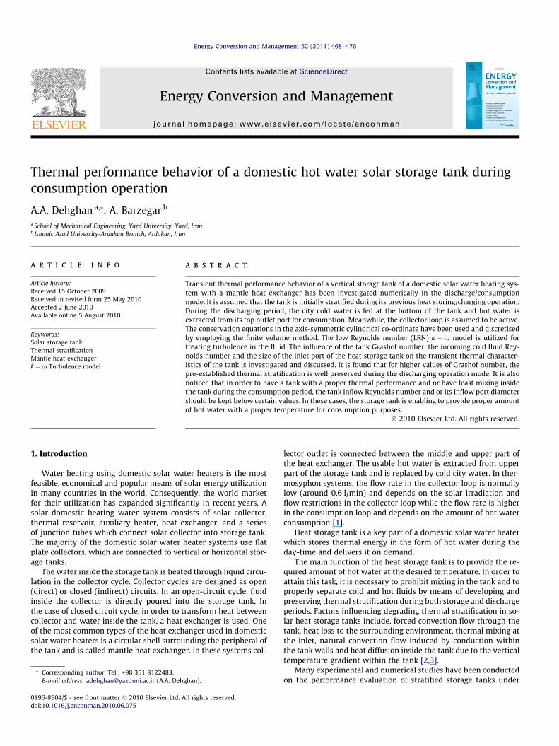
The physical shape of the problem is in the form of a verticalcylinder including a shell type mantle heat exchanger acting as ahot water jacket. A schematic cut view of the modeled thermalstorage tank and the computational domain of the problem is illus-trated in Fig. 1. As a two dimensional modeling is considered, it isassumed that the outlet hot fluid from collector is uniformly in-jected at the upper part of the mantle heat exchanger and is ex-tracted from its lower part after exchanging heat with the tankfluid and is returned to the solar collector. Therefore, inlet flowvelocity to the heat exchanger is determined by collector flow rateand the cross sectional area of heat exchanger. The storage tankheight is H, and its radius, R, is considered to be 0.25H and thewidth of mantle heat exchanger gap is considered to be 0.02H. Also
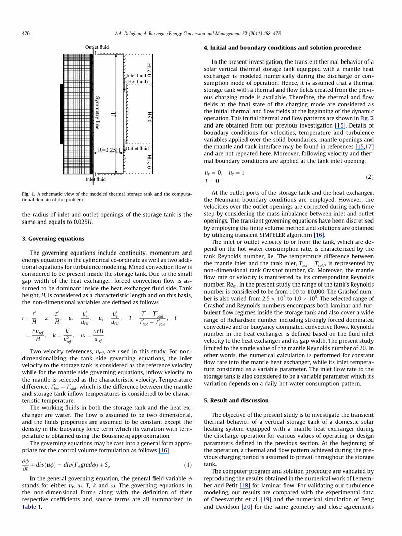
Fig. 1. A schematic view of the modeled thermal storage tank and the computa-tional domain of the problem.
470 A.A. Dehghan, A. Barzegar / Energy Conversion and Management 52 (2011) 468–476
the radius of inlet and outlet openings of the storage tank is thesame and equals to 0.025H.
3. Governing equations
The governing equations include continuity, momentum andenergy equations in the cylindrical co-ordinate as well as two addi-tional equations for turbulence modeling. Mixed convection flow isconsidered to be present inside the storage tank. Due to the smallgap width of the heat exchanger, forced convection flow is as-sumed to be dominant inside the heat exchanger fluid side. Tankheight, H, is considered as a characteristic length and on this basis,the non-dimensional variables are defined as follows
r ¼ r0
H; z ¼ z0
H; ur ¼
u0ruref
; uz ¼u0z
uref; T ¼ T 0 � T 0cold
T 0hot � T 0cold
; t
¼ t0uref
H; k ¼ k0
u2ref
; x ¼ x0Huref
Two velocity references, uref, are used in this study. For non-dimensionalizing the tank side governing equations, the inletvelocity to the storage tank is considered as the reference velocitywhile for the mantle side governing equations, inflow velocity tothe mantle is selected as the characteristic velocity. Temperaturedifference, T 0hot � T 0cold, which is the difference between the mantleand storage tank inflow temperatures is considered to be charac-teristic temperature.
The working fluids in both the storage tank and the heat ex-changer are water. The flow is assumed to be two dimensional,and the fluids properties are assumed to be constant except thedensity in the buoyancy force term which its variation with tem-perature is obtained using the Boussinesq approximation.
The governing equations may be cast into a general form appro-priate for the control volume formulation as follows [16]
@/@tþ divðu/Þ ¼ divðC/grad/Þ þ S/ ð1Þ
In the general governing equation, the general field variable /stands for either ur, uz, T, k and x. The governing equations inthe non-dimensional forms along with the definition of theirrespective coefficients and source terms are all summarized inTable 1.
4. Initial and boundary conditions and solution procedure
In the present investigation, the transient thermal behavior of asolar vertical thermal storage tank equipped with a mantle heatexchanger is modeled numerically during the discharge or con-sumption mode of operation. Hence, it is assumed that a thermalstorage tank with a thermal and flow fields created from the previ-ous charging mode is available. Therefore, the thermal and flowfields at the final state of the charging mode are considered asthe initial thermal and flow fields at the beginning of the dynamicoperation. This initial thermal and flow patterns are shown in Fig. 2and are obtained from our previous investigation [15]. Details ofboundary conditions for velocities, temperature and turbulencevariables applied over the solid boundaries, mantle openings andthe mantle and tank interface may be found in references [15,17]and are not repeated here. Moreover, following velocity and ther-mal boundary conditions are applied at the tank inlet opening.
ur ¼ 0; uz ¼ 1T ¼ 0
ð2Þ
At the outlet ports of the storage tank and the heat exchanger,the Neumann boundary conditions are employed. However, thevelocities over the outlet openings are corrected during each timestep by considering the mass imbalance between inlet and outletopenings. The transient governing equations have been discretisedby employing the finite volume method and solutions are obtainedby utilizing transient SIMPELER algorithm [16].
The inlet or outlet velocity to or from the tank, which are de-pend on the hot water consumption rate, is characterized by thetank Reynolds number, Re. The temperature difference betweenthe mantle inlet and the tank inlet, T 0hot � T 0cold, is represented bynon-dimensional tank Grashof number, Gr. Moreover, the mantleflow rate or velocity is manifested by its corresponding Reynoldsnumber, Rem. In the present study the range of the tank’s Reynoldsnumber is considered to be from 100 to 10,000. The Grashof num-ber is also varied from 2.5 � 103 to 1.0 � 109. The selected range ofGrashof and Reynolds numbers encompass both laminar and tur-bulent flow regimes inside the storage tank and also cover a widerange of Richardson number including strongly forced dominatedconvective and or buoyancy dominated convective flows. Reynoldsnumber in the heat exchanger is defined based on the fluid inletvelocity to the heat exchanger and its gap width. The present studylimited to the single value of the mantle Reynolds number of 20. Inother words, the numerical calculation is performed for constantflow rate into the mantle heat exchanger, while its inlet tempera-ture considered as a variable parameter. The inlet flow rate to thestorage tank is also considered to be a variable parameter which itsvariation depends on a daily hot water consumption pattern.
5. Result and discussion
The objective of the present study is to investigate the transientthermal behavior of a vertical storage tank of a domestic solarheating system equipped with a mantle heat exchanger duringthe discharge operation for various values of operating or designparameters defined in the previous section. At the beginning ofthe operation, a thermal and flow pattern achieved during the pre-vious charging period is assumed to prevail throughout the storagetank.
The computer program and solution procedure are validated byreproducing the results obtained in the numerical work of Lemem-ber and Petit [18] for laminar flow. For validating our turbulencemodeling, our results are compared with the experimental dataof Cheeswright et al. [19] and the numerical simulation of Pengand Davidson [20] for the same geometry and close agreements
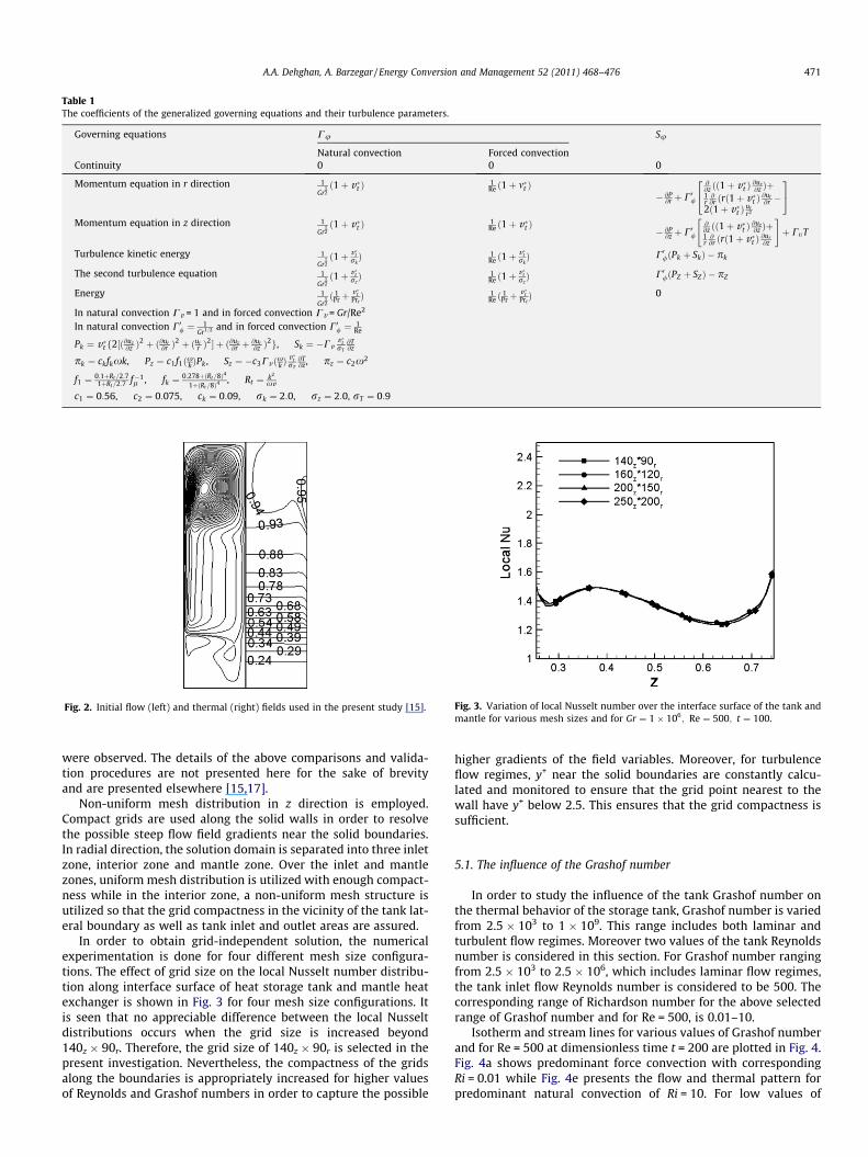
Table 1The coefficients of the generalized governing equations and their turbulence parameters.
Governing equations Cu Su
Natural convection Forced convectionContinuity 0 0 0
Momentum equation in r direction 1
Gr12ð1þ v�t Þ 1
Re ð1þ m�t Þ� @P
@r þ C0/
@@z ðð1þ v�t Þ @uz
@z Þþ1r@@r ðrð1þ v�t Þ @ur
@r �2ð1þ v�t Þ ur
r2
24
35
Momentum equation in z direction 1
Gr12ð1þ v�t Þ 1
Re ð1þ v�t Þ � @P@z þ C0/
@@z ðð1þ v�t Þ @uz
@z Þþ1r@@r ðrð1þ v�t Þ @ur
@z
" #þ CtT
Turbulence kinetic energy 1
Gr12ð1þ v�t
rkÞ 1
Re ð1þv�trkÞ C0/ðPk þ SkÞ � pk
The second turbulence equation 1
Gr12ð1þ v�t
rzÞ 1
Re ð1þv�trzÞ C0/ðPZ þ SZÞ � pZ
Energy 1
Gr12ð 1
Prþv�tPrtÞ 1
Re ð 1Prþ
v�tPrtÞ 0
In natural convection Cv = 1 and in forced convection Cv = Gr/Re2
In natural convection C0/ ¼ 1Gr1=2 and in forced convection C0/ ¼ 1
Re
Pk ¼ v�t f2½ð@uz@z Þ
2 þ ð@ur@r Þ
2 þ ðurr Þ
2� þ ð@uz@r þ
@ur@z Þ
2g, Sk ¼ �Cvv�trT
@T@z
pk ¼ ckfkxk, Pz ¼ c1f1ðxk ÞPk , Sz ¼ �c3Cv ðxk Þv�trT
@T@z, pz ¼ c2x2
f1 ¼ 0:1þRt=2:71þRt=2:7 f�1
l , fk ¼ 0:278þðRt=8Þ4
1þðRt=8Þ4, Rt ¼ k2
xv
c1 ¼ 0:56, c2 ¼ 0:075, ck ¼ 0:09, rk ¼ 2:0, rz ¼ 2:0, rT ¼ 0:9
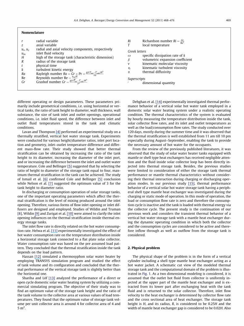
Fig. 2. Initial flow (left) and thermal (right) fields used in the present study [15]. Fig. 3. Variation of local Nusselt number over the interface surface of the tank andmantle for various mesh sizes and for Gr ¼ 1� 106; Re ¼ 500; t ¼ 100.
A.A. Dehghan, A. Barzegar / Energy Conversion and Management 52 (2011) 468–476 471
were observed. The details of the above comparisons and valida-tion procedures are not presented here for the sake of brevityand are presented elsewhere [15,17].
Non-uniform mesh distribution in z direction is employed.Compact grids are used along the solid walls in order to resolvethe possible steep flow field gradients near the solid boundaries.In radial direction, the solution domain is separated into three inletzone, interior zone and mantle zone. Over the inlet and mantlezones, uniform mesh distribution is utilized with enough compact-ness while in the interior zone, a non-uniform mesh structure isutilized so that the grid compactness in the vicinity of the tank lat-eral boundary as well as tank inlet and outlet areas are assured.
In order to obtain grid-independent solution, the numericalexperimentation is done for four different mesh size configura-tions. The effect of grid size on the local Nusselt number distribu-tion along interface surface of heat storage tank and mantle heatexchanger is shown in Fig. 3 for four mesh size configurations. Itis seen that no appreciable difference between the local Nusseltdistributions occurs when the grid size is increased beyond140z � 90r. Therefore, the grid size of 140z � 90r is selected in thepresent investigation. Nevertheless, the compactness of the gridsalong the boundaries is appropriately increased for higher valuesof Reynolds and Grashof numbers in order to capture the possible
higher gradients of the field variables. Moreover, for turbulenceflow regimes, y+ near the solid boundaries are constantly calcu-lated and monitored to ensure that the grid point nearest to thewall have y+ below 2.5. This ensures that the grid compactness issufficient.
5.1. The influence of the Grashof number
In order to study the influence of the tank Grashof number onthe thermal behavior of the storage tank, Grashof number is variedfrom 2.5 � 103 to 1 � 109. This range includes both laminar andturbulent flow regimes. Moreover two values of the tank Reynoldsnumber is considered in this section. For Grashof number rangingfrom 2.5 � 103 to 2.5 � 106, which includes laminar flow regimes,the tank inlet flow Reynolds number is considered to be 500. Thecorresponding range of Richardson number for the above selectedrange of Grashof number and for Re = 500, is 0.01–10.
Isotherm and stream lines for various values of Grashof numberand for Re = 500 at dimensionless time t = 200 are plotted in Fig. 4.Fig. 4a shows predominant force convection with correspondingRi = 0.01 while Fig. 4e presents the flow and thermal pattern forpredominant natural convection of Ri = 10. For low values of
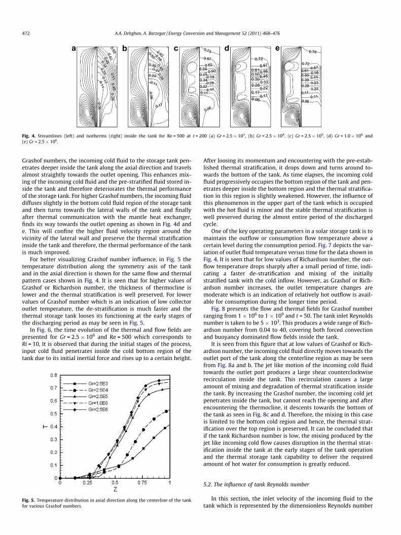
Fig. 4. Streamlines (left) and isotherms (right) inside the tank for Re = 500 at t = 200 (a) Gr = 2.5 � 103, (b) Gr = 2.5 � 104, (c) Gr = 2.5 � 105, (d) Gr = 1.0 � 106 and(e) Gr = 2.5 � 106.
472 A.A. Dehghan, A. Barzegar / Energy Conversion and Management 52 (2011) 468–476
Grashof numbers, the incoming cold fluid to the storage tank pen-etrates deeper inside the tank along the axial direction and travelsalmost straightly towards the outlet opening. This enhances mix-ing of the incoming cold fluid and the pre-stratified fluid stored in-side the tank and therefore deteriorates the thermal performanceof the storage tank. For higher Grashof numbers, the incoming fluiddiffuses slightly in the bottom cold fluid region of the storage tankand then turns towards the lateral walls of the tank and finallyafter thermal communication with the mantle heat exchanger,finds its way towards the outlet opening as shown in Fig. 4d ande. This will confine the higher fluid velocity region around thevicinity of the lateral wall and preserve the thermal stratificationinside the tank and therefore, the thermal performance of the tankis much improved.
For better visualizing Grashof number influence, in Fig. 5 thetemperature distribution along the symmetry axis of the tankand in the axial direction is shown for the same flow and thermalpattern cases shown in Fig. 4. It is seen that for higher values ofGrashof or Richardson number, the thickness of thermocline islower and the thermal stratification is well preserved. For lowervalues of Grashof number which is an indication of low collectoroutlet temperature, the de-stratification is much faster and thethermal storage tank looses its functioning at the early stages ofthe discharging period as may be seen in Fig. 5.
In Fig. 6, the time evolution of the thermal and flow fields arepresented for Gr = 2.5 � 106 and Re = 500 which corresponds toRi = 10, It is observed that during the initial stages of the process,input cold fluid penetrates inside the cold bottom region of thetank due to its initial inertial force and rises up to a certain height.
Fig. 5. Temperature distribution in axial direction along the centerline of the tankfor various Grashof numbers.
After loosing its momentum and encountering with the pre-estab-lished thermal stratification, it drops down and turns around to-wards the bottom of the tank. As time elapses, the incoming coldfluid progressively occupies the bottom region of the tank and pen-etrates deeper inside the bottom region and the thermal stratifica-tion in this region is slightly weakened. However, the influence ofthis phenomenon in the upper part of the tank which is occupiedwith the hot fluid is minor and the stable thermal stratification iswell preserved during the almost entire period of the dischargedcycle.
One of the key operating parameters in a solar storage tank is tomaintain the outflow or consumption flow temperature above acertain level during the consumption period. Fig. 7 depicts the var-iation of outlet fluid temperature versus time for the data shown inFig. 4. It is seen that for low values of Richardson number, the out-flow temperature drops sharply after a small period of time, indi-cating a faster de-stratification and mixing of the initiallystratified tank with the cold inflow. However, as Grashof or Rich-ardson number increases, the outlet temperature changes aremoderate which is an indication of relatively hot outflow is avail-able for consumption during the longer time period.
Fig. 8 presents the flow and thermal fields for Grashof numberranging from 1 � 106 to 1 � 109 and t = 50. The tank inlet Reynoldsnumber is taken to be 5 � 103. This produces a wide range of Rich-ardson number from 0.04 to 40, covering both forced convectionand buoyancy dominated flow fields inside the tank.
It is seen from this figure that at low values of Grashof or Rich-ardson number, the incoming cold fluid directly moves towards theoutlet port of the tank along the centerline region as may be seenfrom Fig. 8a and b. The jet like motion of the incoming cold fluidtowards the outlet port produces a large shear counterclockwiserecirculation inside the tank. This recirculation causes a largeamount of mixing and degradation of thermal stratification insidethe tank. By increasing the Grashof number, the incoming cold jetpenetrates inside the tank, but cannot reach the opening and afterencountering the thermocline, it descents towards the bottom ofthe tank as seen in Fig. 8c and d. Therefore, the mixing in this caseis limited to the bottom cold region and hence, the thermal strat-ification over the top region is preserved. It can be concluded thatif the tank Richardson number is low, the mixing produced by thejet like incoming cold flow causes disruption in the thermal strat-ification inside the tank at the early stages of the tank operationand the thermal storage tank capability to deliver the requiredamount of hot water for consumption is greatly reduced.
5.2. The influence of tank Reynolds number
In this section, the inlet velocity of the incoming fluid to thetank which is represented by the dimensionless Reynolds number
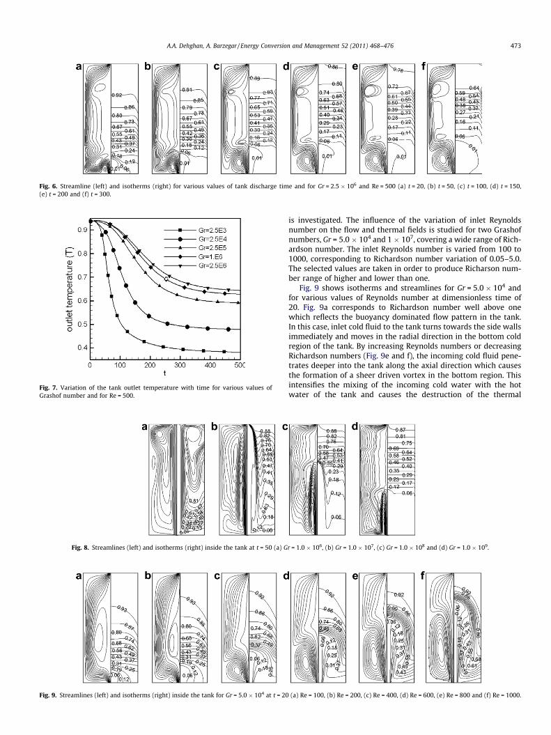
Fig. 6. Streamline (left) and isotherms (right) for various values of tank discharge time and for Gr = 2.5 � 106 and Re = 500 (a) t = 20, (b) t = 50, (c) t = 100, (d) t = 150,(e) t = 200 and (f) t = 300.
Fig. 7. Variation of the tank outlet temperature with time for various values ofGrashof number and for Re = 500.
Fig. 8. Streamlines (left) and isotherms (right) inside the tank at t = 50 (a) G
Fig. 9. Streamlines (left) and isotherms (right) inside the tank for Gr = 5.0 � 104 at t = 20
A.A. Dehghan, A. Barzegar / Energy Conversion and Management 52 (2011) 468–476 473
is investigated. The influence of the variation of inlet Reynoldsnumber on the flow and thermal fields is studied for two Grashofnumbers, Gr = 5.0 � 104 and 1 � 107, covering a wide range of Rich-ardson number. The inlet Reynolds number is varied from 100 to1000, corresponding to Richardson number variation of 0.05–5.0.The selected values are taken in order to produce Richarson num-ber range of higher and lower than one.
Fig. 9 shows isotherms and streamlines for Gr = 5.0 � 104 andfor various values of Reynolds number at dimensionless time of20. Fig. 9a corresponds to Richardson number well above onewhich reflects the buoyancy dominated flow pattern in the tank.In this case, inlet cold fluid to the tank turns towards the side wallsimmediately and moves in the radial direction in the bottom coldregion of the tank. By increasing Reynolds numbers or decreasingRichardson numbers (Fig. 9e and f), the incoming cold fluid pene-trates deeper into the tank along the axial direction which causesthe formation of a sheer driven vortex in the bottom region. Thisintensifies the mixing of the incoming cold water with the hotwater of the tank and causes the destruction of the thermal
r = 1.0 � 106, (b) Gr = 1.0 � 107, (c) Gr = 1.0 � 108 and (d) Gr = 1.0 � 109.
(a) Re = 100, (b) Re = 200, (c) Re = 400, (d) Re = 600, (e) Re = 800 and (f) Re = 1000.
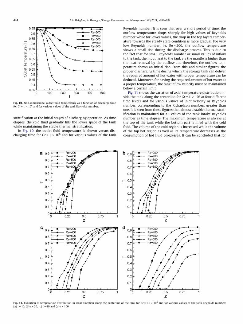
Fig. 10. Non-dimensional outlet fluid temperature as a function of discharge timefor Gr = 1 � 106 and for various values of the tank Reynolds number.
474 A.A. Dehghan, A. Barzegar / Energy Conversion and Management 52 (2011) 468–476
stratification at the initial stages of discharging operation. As timeelapses, the cold fluid gradually fills the lower space of the tankwhile maintaining the stable thermal stratification.
In Fig. 10, the outlet fluid temperature is shown versus dis-charging time for Gr = 1 � 106 and for various values of the tank
Fig. 11. Evolution of temperature distribution in axial direction along the centerline o(a) t = 10, (b) t = 20, (c) t = 40 and (d) t = 100.
Reynolds number. It is seen that over a short period of time, theoutflow temperature drops sharply for high values of Reynoldsnumber while for lower values, the drop in the top layers temper-ature towards the steady state condition is more gradual. For verylow Reynolds number, i.e. Re = 200, the outflow temperatureshows a small rise during the discharge process. This is due tothe fact that for small Reynolds number or small values of inflowto the tank, the input heat to the tank via the mantle is higher thanthe heat removal by the outflow and therefore, the outflow tem-perature shows an initial rise. From this and similar figures, theproper discharging time during which, the storage tank can deliverthe required amount of hot water with proper temperature can bededuced. Moreover, for having the required amount of hot water ata proper temperature, the tank inflow velocity must be maintainedbelow a certain limit.
Fig. 11 shows the variation of axial temperature distribution in-side the tank along the centerline for Gr = 1 � 106 at four differenttime levels and for various values of inlet velocity or Reynoldsnumber, corresponding to the Richardson numbers greater thanone. It is seen from these figures that almost a stable thermal strat-ification is maintained for all values of the tank intake Reynoldsnumber as time elapses. The maximum temperature is always atthe top of the tank while the bottom part is filled with the coldfluid. The volume of the cold region is increased while the volumeof the top hot region as well as its temperature decreases as theconsumption of hot fluid progresses. It can be concluded that for
f the tank for Gr = 1.0 � 106 and for various values of the tank Reynolds number:
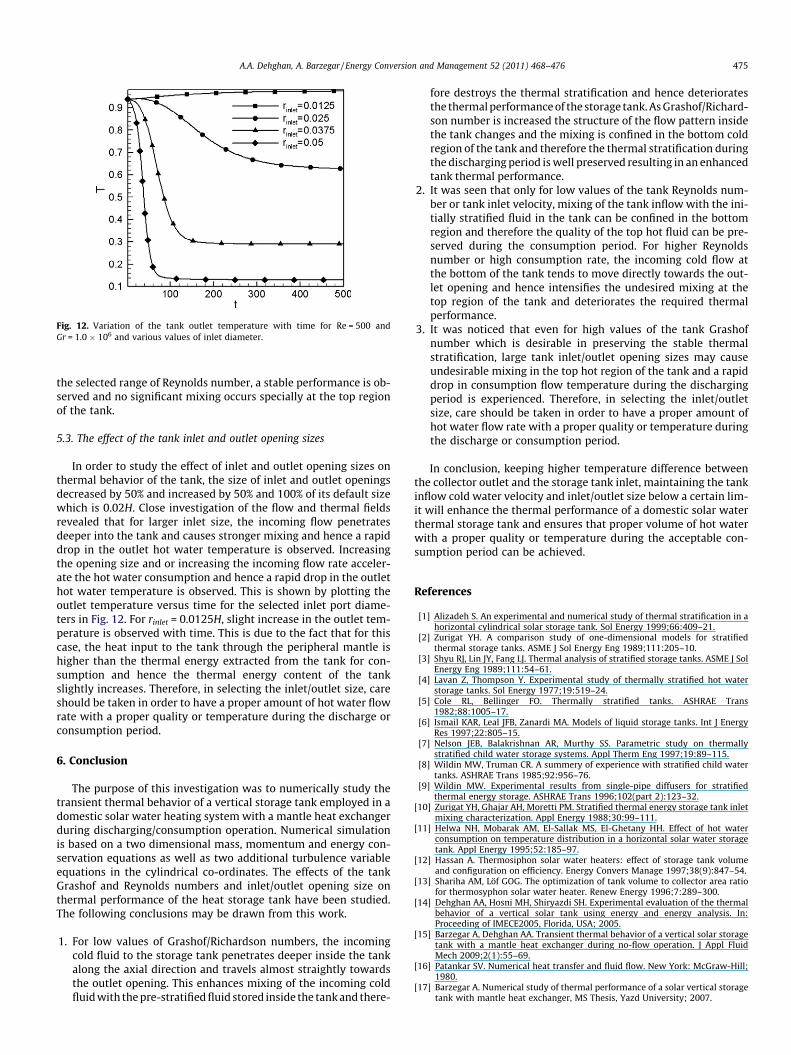
Fig. 12. Variation of the tank outlet temperature with time for Re = 500 andGr = 1.0 � 106 and various values of inlet diameter.
A.A. Dehghan, A. Barzegar / Energy Conversion and Management 52 (2011) 468–476 475
the selected range of Reynolds number, a stable performance is ob-served and no significant mixing occurs specially at the top regionof the tank.
5.3. The effect of the tank inlet and outlet opening sizes
In order to study the effect of inlet and outlet opening sizes onthermal behavior of the tank, the size of inlet and outlet openingsdecreased by 50% and increased by 50% and 100% of its default sizewhich is 0.02H. Close investigation of the flow and thermal fieldsrevealed that for larger inlet size, the incoming flow penetratesdeeper into the tank and causes stronger mixing and hence a rapiddrop in the outlet hot water temperature is observed. Increasingthe opening size and or increasing the incoming flow rate acceler-ate the hot water consumption and hence a rapid drop in the outlethot water temperature is observed. This is shown by plotting theoutlet temperature versus time for the selected inlet port diame-ters in Fig. 12. For rinlet = 0.0125H, slight increase in the outlet tem-perature is observed with time. This is due to the fact that for thiscase, the heat input to the tank through the peripheral mantle ishigher than the thermal energy extracted from the tank for con-sumption and hence the thermal energy content of the tankslightly increases. Therefore, in selecting the inlet/outlet size, careshould be taken in order to have a proper amount of hot water flowrate with a proper quality or temperature during the discharge orconsumption period.
6. Conclusion
The purpose of this investigation was to numerically study thetransient thermal behavior of a vertical storage tank employed in adomestic solar water heating system with a mantle heat exchangerduring discharging/consumption operation. Numerical simulationis based on a two dimensional mass, momentum and energy con-servation equations as well as two additional turbulence variableequations in the cylindrical co-ordinates. The effects of the tankGrashof and Reynolds numbers and inlet/outlet opening size onthermal performance of the heat storage tank have been studied.The following conclusions may be drawn from this work.
1. For low values of Grashof/Richardson numbers, the incomingcold fluid to the storage tank penetrates deeper inside the tankalong the axial direction and travels almost straightly towardsthe outlet opening. This enhances mixing of the incoming coldfluid with the pre-stratified fluid stored inside the tank and there-
fore destroys the thermal stratification and hence deterioratesthe thermal performance of the storage tank. As Grashof/Richard-son number is increased the structure of the flow pattern insidethe tank changes and the mixing is confined in the bottom coldregion of the tank and therefore the thermal stratification duringthe discharging period is well preserved resulting in an enhancedtank thermal performance.
2. It was seen that only for low values of the tank Reynolds num-ber or tank inlet velocity, mixing of the tank inflow with the ini-tially stratified fluid in the tank can be confined in the bottomregion and therefore the quality of the top hot fluid can be pre-served during the consumption period. For higher Reynoldsnumber or high consumption rate, the incoming cold flow atthe bottom of the tank tends to move directly towards the out-let opening and hence intensifies the undesired mixing at thetop region of the tank and deteriorates the required thermalperformance.
3. It was noticed that even for high values of the tank Grashofnumber which is desirable in preserving the stable thermalstratification, large tank inlet/outlet opening sizes may causeundesirable mixing in the top hot region of the tank and a rapiddrop in consumption flow temperature during the dischargingperiod is experienced. Therefore, in selecting the inlet/outletsize, care should be taken in order to have a proper amount ofhot water flow rate with a proper quality or temperature duringthe discharge or consumption period.
In conclusion, keeping higher temperature difference betweenthe collector outlet and the storage tank inlet, maintaining the tankinflow cold water velocity and inlet/outlet size below a certain lim-it will enhance the thermal performance of a domestic solar waterthermal storage tank and ensures that proper volume of hot waterwith a proper quality or temperature during the acceptable con-sumption period can be achieved.
References
[1] Alizadeh S. An experimental and numerical study of thermal stratification in ahorizontal cylindrical solar storage tank. Sol Energy 1999;66:409–21.
[2] Zurigat YH. A comparison study of one-dimensional models for stratifiedthermal storage tanks. ASME J Sol Energy Eng 1989;111:205–10.
[3] Shyu RJ, Lin JY, Fang LJ. Thermal analysis of stratified storage tanks. ASME J SolEnergy Eng 1989;111:54–61.
[4] Lavan Z, Thompson Y. Experimental study of thermally stratified hot waterstorage tanks. Sol Energy 1977;19:519–24.
[5] Cole RL, Bellinger FO. Thermally stratified tanks. ASHRAE Trans1982;88:1005–17.
[6] Ismail KAR, Leal JFB, Zanardi MA. Models of liquid storage tanks. Int J EnergyRes 1997;22:805–15.
[7] Nelson JEB, Balakrishnan AR, Murthy SS. Parametric study on thermallystratified child water storage systems. Appl Therm Eng 1997;19:89–115.
[8] Wildin MW, Truman CR. A summery of experience with stratified child watertanks. ASHRAE Trans 1985;92:956–76.
[9] Wildin MW. Experimental results from single-pipe diffusers for stratifiedthermal energy storage. ASHRAE Trans 1996;102(part 2):123–32.
[10] Zurigat YH, Ghajar AH, Moretti PM. Stratified thermal energy storage tank inletmixing characterization. Appl Energy 1988;30:99–111.
[11] Helwa NH, Mobarak AM, El-Sallak MS, El-Ghetany HH. Effect of hot waterconsumption on temperature distribution in a horizontal solar water storagetank. Appl Energy 1995;52:185–97.
[12] Hassan A. Thermosiphon solar water heaters: effect of storage tank volumeand configuration on efficiency. Energy Convers Manage 1997;38(9):847–54.
[13] Shariha AM, Löf GOG. The optimization of tank volume to collector area ratiofor thermosyphon solar water heater. Renew Energy 1996;7:289–300.
[14] Dehghan AA, Hosni MH, Shiryazdi SH. Experimental evaluation of the thermalbehavior of a vertical solar tank using energy and energy analysis. In:Proceeding of IMECE2005, Florida, USA; 2005.
[15] Barzegar A, Dehghan AA. Transient thermal behavior of a vertical solar storagetank with a mantle heat exchanger during no-flow operation. J Appl FluidMech 2009;2(1):55–69.
[16] Patankar SV. Numerical heat transfer and fluid flow. New York: McGraw-Hill;1980.
[17] Barzegar A. Numerical study of thermal performance of a solar vertical storagetank with mantle heat exchanger, MS Thesis, Yazd University; 2007.

476 A.A. Dehghan, A. Barzegar / Energy Conversion and Management 52 (2011) 468–476
[18] Lemember A, Petit P. Laminar natural convection in a laterally heated andupper cooled vertical cylindrical enclosure. Int J Heat Mass Transfer1998;41:2437–54.
[19] Cheeswright R, King KJ, Ziai S. Experimental data for the validation ofcomputer codes for the prediction of tow-dimensional buoyant cavity flows.In: Humphrey JAC, Avedisian CT, Le Tourneau BW, Chen MM, editors.Significant questions in buoyancy affected enclosure or cavity flows HTD60.ASME; 1986. p. 75–81.
[20] Peng SH, Davidson L. Computation of turbulent buoyant flows in enclosureswith low-Reynolds-number k �x models. Int J Heat Fluid Flow1999;20:172–84.
Related Documents