International Journal of Technical Innovation in Modern Engineering & Science (IJTIMES) Impact Factor: 5.22 (SJIF-2017), e-ISSN: 2455-2585 Volume 4, Issue 6, June-2018 IJTIMES-2018@All rights reserved 8 Thermal Analysis of Disc brake Using ANSYS Avinash Singh Thakur 1 , Asst. Prof. P.S. Dhakad 2 , 1 Mechanical Engineering Department, NITM, Gwalior 2 Mechanical Engineering Department, NITM, Gwalior Abstract— The disc brake is a mechanism that used for reducing speed or discontinuing the cycle of the vehicle. many times using the brake for vehicle starts to heat producing during braking process, such that disc brake undergoes breakage due to high Temperature. Disc brake design is done through Solidwork and analysis is completed by using ANSYS workbench. The main purpose of this project is to study the Thermal analysis of the Materials for the Cast Iron, and Stainless steel. A comparison between the two materials for the Thermal values and material properties obtained from the Thermal analysis low thermal gradient material is preferred. Hence best appropriate design, low thermal gradient material cast iron is chosen for the Disc Brakes for better result. Keywords— ANSYS, Disc brake, Braking System, FEM, Thermal analysis. I. INTRODUCTION A brake is a device by way of which frictional resistance is found to shifting system member, in order to discontinue the motion of a system. Modern vehicles have disc brakes on the front wheels, and there is a developing fashion to have them at the rear wheels as nicely. The braking system is in truth the matter of power stability and purpose of braking system is to transform mechanical strength of shifting vehicle into some other shape, which leads to lessening the rate of the vehicle. The kinetic energy is converted into the thermal energy via dry friction results, which then is, heat dissipated into the environment [1]. A brake disc plate is definitely fitted to and spins with the wheel. Two brake pads are positioned inner a caliper set up on the knuckle, that is hooked up at the chassis. When the driving force hits the brakes, the brake cylinder strain will increase and the piston pushes the pads into contact with the disc. The friction pressure between the brake pads and disc exerts braking torque on the disc, that's related to the wheel, and the following friction among the tire and the road makes the auto sluggish down. An instance of a disc brake meeting that includes a ventilated disc, a cross-section of a sliding caliper with a single piston, and two brake pads is presented in Figure 1. Figure 1: Disc brake assembly

Welcome message from author
This document is posted to help you gain knowledge. Please leave a comment to let me know what you think about it! Share it to your friends and learn new things together.
Transcript
International Journal of Technical Innovation in Modern
Engineering & Science (IJTIMES) Impact Factor: 5.22 (SJIF-2017), e-ISSN: 2455-2585
Volume 4, Issue 6, June-2018
IJTIMES-2018@All rights reserved 8
Thermal Analysis of Disc brake Using ANSYS
Avinash Singh Thakur1, Asst. Prof. P.S. Dhakad
2,
1Mechanical Engineering Department, NITM, Gwalior
2 Mechanical Engineering Department, NITM, Gwalior
Abstract— The disc brake is a mechanism that used for reducing speed or discontinuing the cycle of the vehicle.
many times using the brake for vehicle starts to heat producing during braking process, such that disc brake
undergoes breakage due to high Temperature. Disc brake design is done through Solidwork and analysis is
completed by using ANSYS workbench. The main purpose of this project is to study the Thermal analysis of the
Materials for the Cast Iron, and Stainless steel. A comparison between the two materials for the Thermal values
and material properties obtained from the Thermal analysis low thermal gradient material is preferred. Hence
best appropriate design, low thermal gradient material cast iron is chosen for the Disc Brakes for better result.
Keywords— ANSYS, Disc brake, Braking System, FEM, Thermal analysis.
I. INTRODUCTION
A brake is a device by way of which frictional resistance is found to shifting system member, in order to discontinue
the motion of a system. Modern vehicles have disc brakes on the front wheels, and there is a developing fashion to
have them at the rear wheels as nicely. The braking system is in truth the matter of power stability and purpose of
braking system is to transform mechanical strength of shifting vehicle into some other shape, which leads to
lessening the rate of the vehicle. The kinetic energy is converted into the thermal energy via dry friction results,
which then is, heat dissipated into the environment [1]. A brake disc plate is definitely fitted to and spins with the
wheel. Two brake pads are positioned inner a caliper set up on the knuckle, that is hooked up at the chassis. When
the driving force hits the brakes, the brake cylinder strain will increase and the piston pushes the pads into contact
with the disc. The friction pressure between the brake pads and disc exerts braking torque on the disc, that's related
to the wheel, and the following friction among the tire and the road makes the auto sluggish down. An instance of a
disc brake meeting that includes a ventilated disc, a cross-section of a sliding caliper with a single piston, and two
brake pads is presented in Figure 1.
Figure 1: Disc brake assembly

International Journal of Technical Innovation in Modern Engineering & Science (IJTIMES) Volume 4, Issue 6, June-2018, e-ISSN: 2455-2585, Impact Factor: 5.22 (SJIF-2017)
IJTIMES-2018@All rights reserved 9
A. Disc Brake
A disc brake device normally includes brake disc rotor, brake pads and a caliper. The arrangement of these elements
permits the moving wheel to revel in intense braking in a short stopping distance. The middle a part of the brake disc
has a round aperture, which is located at the wheel hub. It is surrounded by means of some of the holes for the wheel
bolts. The brake disc rotates at the side of the wheel. The normal load, produced when the brake is actuated result in
the era of an in-plane friction pressure at the disc-pad interface. This in turn, produces a brake torque about the
middle of rotation of the wheel. The response to the brake torque is visible in the brake force, between the tire and
ground, which slow the automobile.
Disc brakes work through making use of pressure to two brake pads on different sides of a spinning rotor connected
the hub of a wheel. Disc brake pad are set up in a caliper that sits above the spinning disc. All friction additives of
disc brake are exposed to the air, which facilitates to cool the brake components and braking effectiveness at some
stage in repeated hard stops from higher speeds. A disc brake calls for better hydraulic strain and greater pressure to
attain the equal preventing energy as a similar drum brake. Disc brakes are extensively used for lowering speed
through the friction because of pushing brake pad against a brake disc with a set of calipers. The brake disc normally
made by cast iron, but may additionally in a few cases made by using composites. The contacts conditions between
the disk and pads correspond to warmth flux which is characteristic of the time and space variables. The thermal
boundary situations outside the touch area correspond to convection, radiation and the recognized temperature. The
sliding pace and the frictional warmness flux are time based and there is intensity related with stress increasing
model. Solid disc brake is frequently used on smaller in width, lighter, and much less high-priced compare with
vented disc brake extra using in heavier brake. Solid disc also has various establishing profile likes drilled, grooves
and aggregate each of them. For this challenge, stable disc with opening diverse profile changed into selected that's
everyday disc brake, drilled disc brake, grooves disc brake and combination drilled and grooves disc brake.
B. Braking system
A brake is a tool with the aid of which simulated frictional resistance is carried out to rotating machine part, in order
to stop the movement of a machine. In the process of acting this characteristic, the brakes soak up both kinetic
energy of the shifting member or the ability of electricity given up via objects being reduced by hoists, elevators and
many others. The energy absorbed through brakes is dissipated inside the form of heat. This heat is dissipated into
the encompassing ecosystem to prevent the car, so the brake system need to have the following necessities:
i. The brakes ought to be sturdy sufficient to stop the automobile with in a minimum Distance in an
emergency.
ii. The motive force must have proper manipulate over the vehicle at some stage in braking and the
automobile must no longer skid.
iii. The brakes need to have exact ant fade features i.e. Their usefulness should no longer lower with steady
prolonged utility.
iv. The brakes should have desirable anti-wear residences.
Based on mode of operation brakes are categorized as follows:
Hydraulic brakes.
Electric brakes.
Mechanical brakes.
The mechanical brakes in step with the course of acting pressure can be sub divided into the following businesses:
i. Radial brakes:
In those brakes the pressure performing on the brake drum is in radial course. The radial brake can be
subdivided into outside brakes and internal brakes.
ii. Axial brakes:
In those brakes the force appearing on the brake drum is best within the axial course. e.g. Disc brakes, Cone
brakes.
International Journal of Technical Innovation in Modern Engineering & Science (IJTIMES) Volume 4, Issue 6, June-2018, e-ISSN: 2455-2585, Impact Factor: 5.22 (SJIF-2017)
IJTIMES-2018@All rights reserved 10
C. Heat transfer in Disc brake:
When a system is at a dissimilar temperature than its atmospheres, the Nature attempts to maintain thermal
equilibrium. To do so, as the second law of thermodynamics explains, the thermal energy always moves from the
system of higher temperature to the system of lower temperature.
This transfer of thermal energy occurs due to one or a combination of the three basic heat transport mechanisms:
Conduction, Convection and Radiation.
D. Conduction:
Is the transmission of heat by direct molecular transmission, i.e. by physical connection of the particles within
a medium or between mediums it happens in gases, liquids and solids, in conduction, there is no movement of any of
the material mediums.
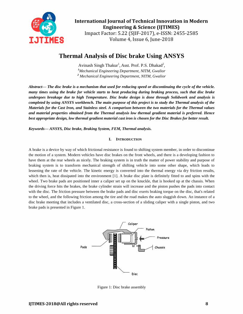
The governing equation for conduction is called the Fourier’s law of heat conduction and it express that the heat
flow per unit area is proportional to the normal temperature gradient, where the proportionality constant is the
thermal conductivity:
Where q is the heat flux perpendicular to a floor of place A, [W]; A is the surface vicinity via which the heat drift
takes place, [m2]; k is the thermal conductivity, [W/(mK)]; T is the temperature, [K] or [°C]; and x is the
perpendicular distance to the surface traveled by means of the heat flux.
E. Convection:
Convection is the heat transfer by means of mass motion of a fluid, when the heated fluid moves away from the heat
supply. It combines conduction with the impact of a contemporary of fluid that movements its heated particles to
cooler areas and update them by way of cooler ones. The float can be both because of buoyancy forces (natural
convection) or due to artificially brought about currents (compelled convection).
The equation that represents convection comes from the Newton’s regulation of cooling and is of the form:
Where h is the convective heat transfer coefficient [W/ (m2K)]; T∞ is the temperature of the cold fluid; and Ts is the
temperature of the surface of the body.
II. FINITE ELEMENT ANALYSIS
To execute the finite element investigation of the piston when the pressure of the gasses acts upon it, a structural
examination using ANSYS Workbench V.14.0 takes place. At this step the investigation of the piston is a linear
static one, when minor modification in rigidity take place, there are no modifications in the direction of the loading,
the materials stay within linear flexible region and miner deformations and stresses are produced. The model of the
piston is designed in Solidwork 2016 and saved in this file as *.igs, and then imported in ANSYS Workbench.
Experimental Piston Model was optimized by with ANSYS that is relate with engineering simulation commercially
used software set allowing a complete group that extents the complete variety of physics, offering right to use to
almost several field of thermal engineering application that a design method needs. The software package uses its
tools to place a virtual product through a rigorous testing procedure like testing a Piston model below totally
different loading circumstances before it turns into a considerable object.
International Journal of Technical Innovation in Modern Engineering & Science (IJTIMES) Volume 4, Issue 6, June-2018, e-ISSN: 2455-2585, Impact Factor: 5.22 (SJIF-2017)
IJTIMES-2018@All rights reserved 11
III. DESIGN AND ANALYSIS OF DISC BRAKE
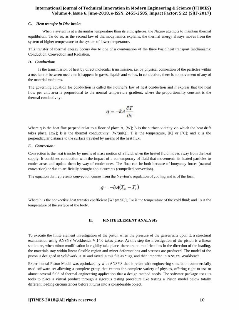
1. Modeling of Disc brake
Two different metals used to design disc brake in this study first one are cast iron and other stainless steel.
Solidwork used to design disc brake and ANSYS used to thermal analysis. The practical use of finite element
modeling is known as FEA which is best understood during the real problem solving. FEA has been widely used by
the automotive industry. It is a very popular tool for design engineers in the product enlargement method. FEA
allows design engineers to analyze their designs while the designs are still in the procedure of an adjustable
computer aided design (Solidwork) model. This helps and gives flexibility to the design engineers to go back and
forth to implement of the FEA analysis results in the whole design process and improve the model. It is important to
understand the FEA basics, modeling techniques, the inherent errors and their effects on the quality of the results so
as to render FEA as a successful design tool. FEA is also used as a computational tool for carrying out engineering
problem analyses.
Figure 2: Geometry of disc brake
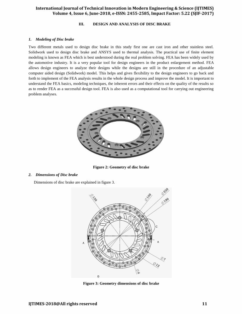
2. Dimensions of Disc brake
Dimensions of disc brake are explained in figure 3.
Figure 3: Geometry dimensions of disc brake

International Journal of Technical Innovation in Modern Engineering & Science (IJTIMES) Volume 4, Issue 6, June-2018, e-ISSN: 2455-2585, Impact Factor: 5.22 (SJIF-2017)
IJTIMES-2018@All rights reserved 12
3. Applying boundary conditions
Figure represents the applied boundary conditions on disc brake has been kept fixed while convection on the top
surface of the disc brake has been applied, to optimize failure of disc brake. Figure shows the applied boundary
conditions of disc brake.
Figure 4: Boundary conditions
IV. MATERIAL PROPERTIES
Stainless steel and Cast iron considered as material in present study. Two types of material design of disc brake used
in this study Properties of material are described below.
Table.5.1: Material Properties for Stainless Steel and Cast Iron
Material Properties Stainless Steel (Model I) Cast Iron (Model II)
Thermal conductivity(w/m k) 36 50
Density , ρ (kg/m3) 7100 6600
Specific heat , c (J/Kg ϲ ) 320 380
Thermal expansion , α (10-6 / k ) 0.12 0.16
Elastic modulus, E (GPa) 210 110
Coefficient of friction, μ 0.5 0.5
Film co-efficient h(w/km2 ) 240 280
Operation conditions
Angular velocity,( rad /s) 50 50
Braking Time Sec 5 6
Hydraulic pressure, P (M pa) 1 1
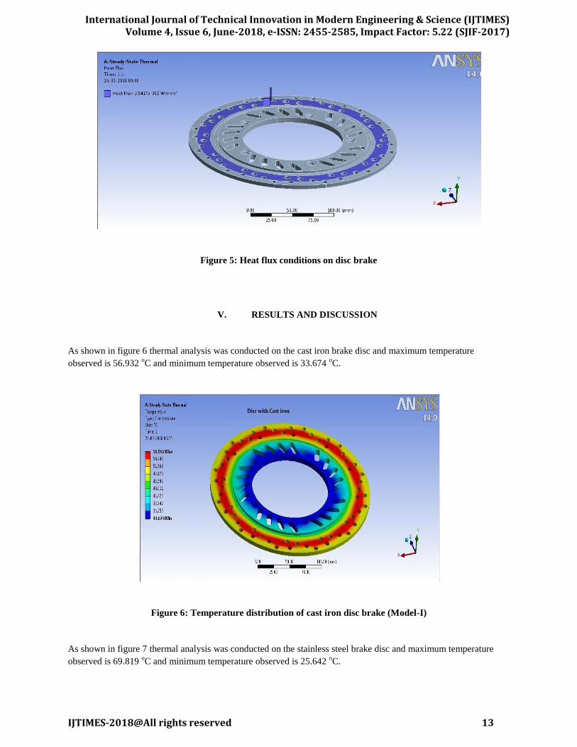
Thermal analysis is used to determine temperature and different thermal quantities that exchange over time. The
change in temperature distribution through the years is critical in many applications which includes in quenching
analysis for warmth treatment. Also of hobby are the temperature distribution effects in thermal stresses which could
reason the failure. In such cases temperature from the brief thermal evaluation for thermal stress assessment. Heat
flux is applied for distinct design shape discs is three.9417e-002 W/mm2.The following figure 5 suggests the result
of thermal analysis in disc brake.
International Journal of Technical Innovation in Modern Engineering & Science (IJTIMES) Volume 4, Issue 6, June-2018, e-ISSN: 2455-2585, Impact Factor: 5.22 (SJIF-2017)
IJTIMES-2018@All rights reserved 13
Figure 5: Heat flux conditions on disc brake
V. RESULTS AND DISCUSSION
As shown in figure 6 thermal analysis was conducted on the cast iron brake disc and maximum temperature
observed is 56.932 oC and minimum temperature observed is 33.674
oC.
Figure 6: Temperature distribution of cast iron disc brake (Model-I)
As shown in figure 7 thermal analysis was conducted on the stainless steel brake disc and maximum temperature
observed is 69.819 oC and minimum temperature observed is 25.642
oC.

International Journal of Technical Innovation in Modern Engineering & Science (IJTIMES) Volume 4, Issue 6, June-2018, e-ISSN: 2455-2585, Impact Factor: 5.22 (SJIF-2017)
IJTIMES-2018@All rights reserved 14
Figure 7: Temperature distribution of Stainless steel disc brake (Model-II)
From the figures 8, given above, we can summarize the results in the following manner: -
Table no. 9.1 Maximum and minimum Temperature Distribution
Materials Temperature Distribution (
oC)
Min Max
Stainless Steel 33.67 56.93
Cast Iron 25.64 69.81
As shown in figure 5.4 thermal analysis was conducted on the cast iron brake disc and maximum Heat flux observed
is 8.2427 W/mm2 and minimum Heat flux observed is 1.6624e-5 W/mm
2.
Figure 8: Heat flux of cast iron disc brake (Model-I)
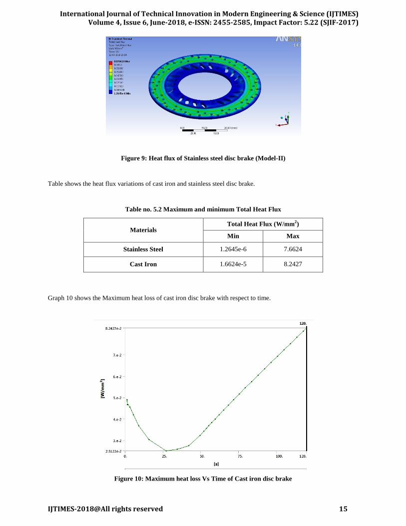
As shown in figure 9 thermal analysis was conducted on the stainless steel brake disc and maximum Heat flux
observed is 7.6624 W/mm2 and minimum Heat flux observed is 1.2645e-6 W/mm
2.
International Journal of Technical Innovation in Modern Engineering & Science (IJTIMES) Volume 4, Issue 6, June-2018, e-ISSN: 2455-2585, Impact Factor: 5.22 (SJIF-2017)
IJTIMES-2018@All rights reserved 15
Figure 9: Heat flux of Stainless steel disc brake (Model-II)
Table shows the heat flux variations of cast iron and stainless steel disc brake.
Table no. 5.2 Maximum and minimum Total Heat Flux
Materials Total Heat Flux (W/mm
2)
Min Max
Stainless Steel 1.2645e-6 7.6624
Cast Iron 1.6624e-5 8.2427
Graph 10 shows the Maximum heat loss of cast iron disc brake with respect to time.
Figure 10: Maximum heat loss Vs Time of Cast iron disc brake
International Journal of Technical Innovation in Modern Engineering & Science (IJTIMES) Volume 4, Issue 6, June-2018, e-ISSN: 2455-2585, Impact Factor: 5.22 (SJIF-2017)
IJTIMES-2018@All rights reserved 16
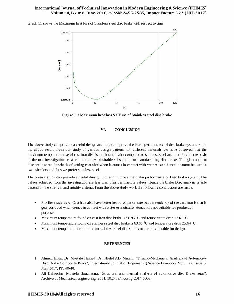
Graph 11 shows the Maximum heat loss of Stainless steel disc brake with respect to time.
Figure 11: Maximum heat loss Vs Time of Stainless steel disc brake
VI. CONCLUSION
The above study can provide a useful design and help to improve the brake performance of disc brake system. From
the above result, from our study of various design patterns for different materials we have observed that the
maximum temperature rise of cast iron disc is much small with compared to stainless steel and therefore on the basic
of thermal investigation, cast iron is the best desirable substantial for manufacturing disc brake. Though, cast iron
disc brake some drawback of getting corroded when it comes in contact with wetness and hence it cannot be used in
two wheelers and thus we prefer stainless steel.
The present study can provide a useful de-sign tool and improve the brake performance of Disc brake system. The
values achieved from the investigation are less than their permissible values. Hence the brake Disc analysis is safe
depend on the strength and rigidity criteria. From the above study work the following conclusions are made:
Profiles made up of Cast iron also have better heat dissipation rate but the tendency of the cast iron is that it
gets corroded when comes in contact with water or moisture. Hence it is not suitable for production
purpose.
Maximum temperature found on cast iron disc brake is 56.93 0C and temperature drop 33.67
0C.
Maximum temperature found on stainless steel disc brake is 69.81 0C and temperature drop 25.64
0C.
Maximum temperature drop found on stainless steel disc so this material is suitable for design.
REFERENCES
1. Ahmad Islahi, Dr. Mostafa Hamed, Dr. Khalid AL- Matani, "Thermo-Mechanical Analysis of Automotive
Disc Brake Composite Rotor", International Journal of Engineering Science Invention, Volume 6 Issue 5,
May 2017, PP. 40-48.
2. Ali Belhocine, Mostefa Bouchetara, "Structural and thermal analysis of automotive disc Brake rotor",
Archive of Mechanical engineering, 2014, 10.2478/meceng-2014-0005.

International Journal of Technical Innovation in Modern Engineering & Science (IJTIMES) Volume 4, Issue 6, June-2018, e-ISSN: 2455-2585, Impact Factor: 5.22 (SJIF-2017)
IJTIMES-2018@All rights reserved 17
3. Deepak S. Hugar, U. B. Kadabadi, "Design and Thermal Analysis of Disc Brake for Minimizing
Temperature", International Research Journal of Engineering and Technology (IRJET), Volume: 04, Issue:
07,July -2017.
4. Jaenudin, J. Jamari, M. Tauviqirrahman, "Thermal Analysis of Disc Brakes using Finite Element Method",
American Institute of Physics, 1788, 030028 (2017); doi: 10.1063/1.4968281.
5. Manjunath T V, Dr Suresh P M, "Structural and Thermal Analysis of Rotor Disc of Disc Brake",
International Journal of Innovative Research in Science, Engineering and Technology, Vol. 2, Issue 12,
December 2013.
6. Manthan Vidiya, Balbir Singh, "Experimental and Numerical Thermal Analysis of Formula Student Racing
Car Disc Brake Design", Journal of Engineering Science and Technology Review, 10 (1), (2017) 138- 147.
7. Rakesh Jaiswal, Anupam Raj Jha, Anush Karki, "Structural And Thermal Analysis Of Disc Brake Using
Solidwork And Ansys", International Journal of Mechanical Engineering and Technology (IJMET),
Volume 7, Issue 1, Jan-Feb 2016, pp. 67-77.
8. Santosh Kumar Kallepalli, Harish Musti, DR.K.Sudhakar Reddy, "Enhancement in Design and Thermal
Analysis Of Disc Brake Rotor", International Journal Of Engineering Sciences & Research Technology,
February, 2017.
9. Shah E Alam, Yuvraj Vidhyadhar, Prashant Sharma, "Thermal Analysis of disc Brakes Rotor", Journal of
Information Sciences and Computing Technologies, Volume 3, Issue 2, April 20, 2015.
10. Subhasis Sarkar, Pravin P. Rathod, A. J. Modi, "Research Paper on Modeling and Simulation of Disc Brake
to Analyze Temperature Distribution using FEA", International Journal for Scientific Research &
Development, Vol. 2, Issue 03, 2014.
11. Mr. Sumeet Satope, Akshaykumar Bote, Swapneel D. Rawool, "Thermal Analysis of Disc Brake",
International Journal for Innovative Research in Science & Technology, Volume 3, Issue 12, May 2017.
12. Swapnil R. Abhang, D.P.Bhaskar, "Design and Analysis of Disc Brake", International Journal of
Engineering Trends and Technology (IJETT), Volume 8 Number 4- Feb 2014.
13. Swapnil Umale,Dheeraj Varma, "Disc Brake Rotor Selection through Finite Element Analysis",
International journal of recent trends in engineering & research, Volume 02, Issue 4; April - 2016.
14. Venkatramanan R, Kumaragurubaran SB, Vishnu Kumar C, "Design and Analysis of Disc Brake Rotor",
International Journal of Applied Engineering Research, Volume 10, 2015.
15. Viraj Parab, Kunal Naik, Prof A. D. Dhale, “Structural and Thermal Analysis of Brake Disc”, IJEDR,
Volume 2, Issue 2, 2014.
16. Reddy, Dr. P Usha Sri, "Heat Transfer Analysis of Automotive Disc Brakes", International Journal of
Advance Research In Science And Engineering, Vol. No.3, Issue No.9, September 2014.
Related Documents