Department of Materials Science and Engineering The University of Sheffield THERAMIN Summer School 12 th -14 th June 2019 Professor Neil C. Hyatt [email protected] @ISL_Sheffield 2019 © The University of Sheffield The views expressed in this talk are the personal opinion of the speaker and do not necessarily reflect those of sponsors or funding agencies Theramin Technical Training School: Hot Isostatic Pressing

Welcome message from author
This document is posted to help you gain knowledge. Please leave a comment to let me know what you think about it! Share it to your friends and learn new things together.
Transcript

Department of Materials Science and Engineering The University of Sheffield
THERAMIN Summer School12th-14th June 2019
Professor Neil C. Hyatt
@ISL_Sheffield
2019 © The University of Sheffield
The views expressed in this talk are the personal opinion of the speaker and do not necessarily reflect those of sponsors or funding agencies
Theramin Technical Training School:
Hot Isostatic Pressing
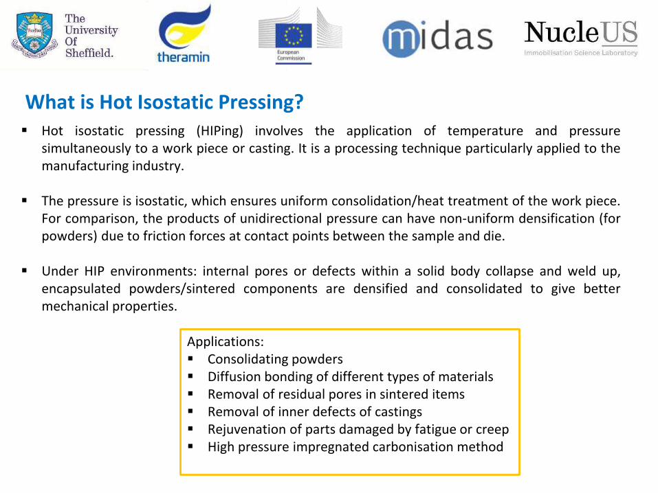
What is Hot Isostatic Pressing? Hot isostatic pressing (HIPing) involves the application of temperature and pressure
simultaneously to a work piece or casting. It is a processing technique particularly applied to themanufacturing industry.
The pressure is isostatic, which ensures uniform consolidation/heat treatment of the work piece.For comparison, the products of unidirectional pressure can have non-uniform densification (forpowders) due to friction forces at contact points between the sample and die.
Under HIP environments: internal pores or defects within a solid body collapse and weld up,encapsulated powders/sintered components are densified and consolidated to give bettermechanical properties.
Applications: Consolidating powders Diffusion bonding of different types of materials Removal of residual pores in sintered items Removal of inner defects of castings Rejuvenation of parts damaged by fatigue or creep High pressure impregnated carbonisation method

History of HIPing
Hot Isostatic Pressing was originally designed for nuclear industry applications (under the name“gas-pressure bonding”).
It was developed by the Battelle Memorial Institute (at the Columbus Laboratories in 1955) onbehalf of the United States Atomic Energy Commission.
The objective was to “develop a process to bond components of a small Zircaloy-clad pin-typenuclear fuel elements while maintaining strict dimensional control”
Conventional fuel cladding fabrication methods (diffusion anneal, hot deformation) producedunsatisfactory results.
Nuclear Timeline: The Shippingport atomic power station(PA; USA) first reach criticality in 1957. The first core used“zirconium-uranium alloy, with a metallurgically bondedZircaloy cladding layer on either side” [1]
Photograph showing the installation of reactor vessel atShippingport, the first US commercial reactor [2]
[1] Naval Nuclear Propulsion (1995) Report on use of low enriched uranium in naval nuclear propulsion.[2] World Nuclear Association, http://world-nuclear.org/information-library/current-and-future-generation/outline-history-of-nuclear-energy.aspx

History of HIPing
HIP Version 1: A 304 stainless steel tube (~3 ft./92 cm) containing the sample pin was sealed atone end and fitted with a two-way gas valve.
Helium gas was used as the pressurising media.
The SS tube was pressurised to 2000 psi (~14 MPa) and inserted into a furnace between 1500 to1650 °F (843-900 °C).
Good bonding results were observed but the temperature dwell time was between 24-36 hours.
[3] Boyer, C. B. (1992) Historical Review of Hip Equipment, Dordrecht, Springer Netherlands.
Helium gas cylinder
304 Stainless steel tube (HIP vessel)
Photograph illustrating a demonstration of the first
HIP system [3]

History of HIPing
Several ruptures of the hot-wall vessels (tubes)occurred during scale up operations.
It was determined that the hot-wall system wouldtherefore be limited in: size, temperature, pressureand operational lifetime.
HIP Version 2: 304 stainless steel forged pressurevessel with a compressor and two single zonecartridge type furnaces. Helium gas was still used asthe pressurising media.
New capabilities: 10,000 psi (~69 MPa) and between1500 to 1650 °F (843-900 °C).
Very good Zircaloy bonding observed with a 6 hourdwell.
[3] Boyer, C. B. (1992) Historical Review of Hip Equipment, Dordrecht, Springer Netherlands.
Photograph: First pressure vessel (top) and accompanying compressor (bottom) [3]

History of HIPing
Between 1960 and 1970, Battelle Memorial Institute acquired two new HIP systems:
- Pressure rated up to 15,000 psi (~100 MPa)- Pressure rated up t0 50,000 psi (~345 MPa)
Improvements were also made in the following areas: furnacedesign (materials and insulation), furnace electrical connectionsand thermocouples, (Be-Cu electrodes), pressure vessel seals andsafety design.
By 1970’s, HIPs were in use by wide industrial users:
Birmingham Small Arms Group (UK), CEA (France), General Electric (Hanford Atomic Products Operations; USA), NASA Lewis Research Center (USA), Lawrence Radiation Laboratory (USA), Argonne National Laboratory (USA), Atomic Weapons Research Establishment(UK), Boeing Company and Bell Telephone Laboratories….to name a few!
[3] Boyer, C. B. (1992) Historical Review of Hip Equipment, Dordrecht, Springer Netherlands.[4] ASME Landmarks Program (1985) The evolution of HIP.
Photograph: Battelle’s large HIP system in the early 1970’s [4]

Modern HIP design
Compressor
Vacuumpump
Motor pump
Coolant lines
Pressure vents
High P tube to the PV
Electrical connections
Pressure vessel
Pressure vessel top closure
Thermal barrierWater jacket
Work piece
Left: Photograph and schematic of HIP pressure vesselRight: Photograph of HIP support equipmentNot shown: Argon gas manifold, user control PC, chiller
HIP control (PIC)

The HIP Process
HIP Cycle:
Stage 1: Simultaneous temperature and pressure ramp (this is the most cost effective HIP cycle)
Stage 2: Hot isostatic pressing (dwell period)
Stage 3: Simultaneous ramp down and release of temperature and pressure
The example shown has a multi-stage ramp segment:
- Ramp to 400 °C @ 5 °C/min, hold for 30 min- Ramp to 750 °C @ 5 °C/min, hold for 15 min- Ramp to 1250 °C @ 7.5 °C/min - Dwell for 2 hours at 1250 °C and 75 MPa- Ramp down to 20 °C and 0 MPa

The HIP Process
Other types of HIP cycle include [5]:
Cold-loading cycle: Temperature is only applied after the pressure ramp has started. Temperature and pressure should reach target at the same time. Good for geometric control
Hot-loading cycle: Pressure is only applied after the temperature has reached the target
temperature. Ideal for glass encapsulated products (early pressure will crack the
glass containment)
Pressure-loading cycle: Temperature is only applied after pressure reaches the target. Allows use of lower temperatures (e.g. for powder recrystallisation)
[5] Loh and Sia (1992) An overview of hot isostatic pressing, Journal of Materials Processing Technology, 30, p. 45-65
Cold-loading cycle
Hot-loading cycle
Pressure-loading cycle

The HIP work piece
Closed porosity materials: No additional containment required (e.g. castings)
Open porosity materials: Need to be vacuum sealed in a canister/capsule.
- Typically fabricated using metals, glass or ceramic
- This process also removes water vapour and air than could lead to oxide formation and affect
the sintering process
- After HIPing, the canister/capsule is removed from by machining to leave the HIPed product
Note: In nuclear applications, the canister would be form part of the overall waste package
(multi-barrier approach)
Schematic of work piece preparation using a powder in a
stainless steel canister

The University of Sheffield currently are the only site
in the UK with the capability for processing radioactive
waste forms by HIP! More information coming later…
No volatile off gas during process
100 % waste loading possible
Hermetically sealed: minimised secondary wastes
Conditioned waste volume minimised
One process for multiple waste streams
Batch process: flexibility and accountability
Range of processing conditions
Up to 60% volume reduction
Photographs of the University of Sheffield HIP with an example of a HIP canister A) pre and B) post processing
N.B. Images not to scale!
Advantages of HIPing (with regards to nuclear waste immobilisation)

HIP for nuclear waste immobilisation - Synroc
Australian Science and Technology Organisation (ANSTO) developed a group of synthetic rock“synroc” based on calcium titanates as hosts for immobilising nuclear fuel reprocessing waste.
Synroc-C is the most studied variant of the synroc group. The phase assemblage is typically acombination of: rutile, hollandite, perovskite and zirconolite. The composition is shown in Table 1.
[6] Vance et al., (2014) Progress at ANSTO on SYNROC, Journal of the Australian Ceramics Society, 50(1), p. 38-48Figure adapted from [7] Ringwood et al., (2014) IN: Radioactive Waste Forms for the Future, Eds. Lutze and Ewing.
Table 1: SYNROC-C composition [6] Synroc-C can incorporate up to 35 wt. % solids waste
without changing the phase assemblage.

HIP processing of Synroc
[7] Ringwood et al., (2014) IN: Radioactive Waste Forms for the Future, Eds. Lutze and Ewing.
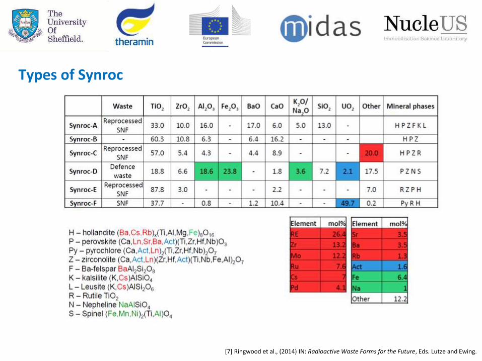
Types of Synroc
[7] Ringwood et al., (2014) IN: Radioactive Waste Forms for the Future, Eds. Lutze and Ewing.
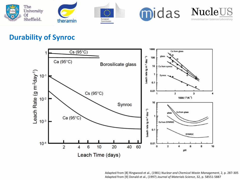
Durability of Synroc
Adapted from [8] Ringwood et al., (1981) Nuclear and Chemical Waste Management, 2, p. 287-305Adapted from [9] Donald et al., (1997) Journal of Materials Science, 32, p. 58551-5887

Case Study 1: Plutonium immobilisation
Figure 1: Pu store (credit: NDA)
The management and safe storage of separated PuO2 is the subject ofinternational scrutiny and concern
Baseline strategy:
Plutonium is considered a zero asset waste Storage planned until 2120 at Sellafield, materials assumed to remain
in place after this date. No costs are currently included in the baseline plan beyond 2120. Plan does not include all infrastructure required to maintain storage
beyond 2120. PuO2 is not considered a passive form for long term storage. A proportion of the stockpile will need to be converted to passive
form before 2120.
Challenges to the baseline strategy:
Management arrangements for plutonium storage are not optimised. Requirements for long term safe storage and secure storage are not
fully developed. Final treatment and disposal route and costs, require definition.
Figure 2: ThoRP storage cans (credit: The Engineer)

Case Study 1: Plutonium immobilisation
Upon completion of fuel reprocessing, the UK will have a stockpile >140t of PuO2
Dual track strategy of immobilisation and reuse by MOX fabrication for LWR
MOX challenges:
- Not all Pu will be suitable (Am-241 ingrowth)
- Industrial scale MOX fabrication difficult
Pu wasteform required to immobilise wastes for over 100,000 years until the radiotoxicity returns to
natural uranium levels
Hot isostatic pressing identified as possible thermal treatment route for PuO2 wastes.
Advantages of HIPing Pu:
Uniform incorporation of radionuclidesBatch process (inventory control)No off-gas production No secondary wastes producedHermetically sealed wasteformUp to 60% volume reductionSignificant cost saving
Time

Case Study 1: Plutonium immobilisation
Zirconolite glass/ceramic host
CaZrTi2O7: high durability and radiation tolerance
Natural mineral analogues (predict long term behaviour)
Readily incorporates actinides and rare earths
Full ceramic suitable for high Pu residues, glass-ceramics
suitable for low Pu residues
70 wt.% glass/ceramic

Magnesium Borosilicate Glass
MBS-M (U)
Sample Name Mg(OH)2 (g) Mg (g) H3BO3 (g) SiO2 (g) U3O8 (g)Waste loading
(wt. %)
MBS-M (U) (high) 4.694 2.816 12.208 6.040 18.820 59.1
MBS-C (U) (low) 18.109 1.132 22.200 10.983 3.801 41.0
200 µm200 µm
MBS-C (U)
Case Study 2: Active HIPing (Magnox sludge)

Crystalline phases are predominantly quartz, uranium oxides and suanite (a magnesium borate –Mg2B2O5). No unreacted Mg metal detected
Bulk quartz appears largely unreacted, key binder is likely a magnesium borate Further characterisation required to confirm assignments and UOx composition (by oxidation
state).
MBS-M (U, high)
MBS-C (U, low)
Case Study 2: Active HIPing (Magnox sludge)
Related Documents


