Energies 2022, 15, 3930. https://doi.org/10.3390/en15113930 www.mdpi.com/journal/energies Review Theory and Practices of Li‐Ion Battery Thermal Management for Electric and Hybrid Electric Vehicles Rajib Mahamud 1, * and Chanwoo Park 2, * 1 Department of Mechanical Engineering, Idaho State University, Pocatello, ID 83201, USA 2 Department of Mechanical Engineering, University of Missouri, Columbia, MO 65211, USA * Correspondence: [email protected] (R.M.); [email protected] (C.P.) Abstract: This article surveys the mathematical principles essential for understanding the thermal management of Li‐ion batteries, the current technological state of the art, and the solution. Since the thermal management of electric drive vehicles has environmental, economic, and safety impacts, this review focuses on the efficient methods of battery thermal management (BTM) that were pro‐ posed to overcome the major challenges in the electric vehicle industry. The first section examines the perspective of battery‐driven vehicles, the principles of Li‐ion batteries with a thermal runaway, and their implication for battery safety. The second section discusses mathematical approaches for effective BTM modeling, including the thermal‐fluidic network model, lumped capacitance model, spatial resolution lumped capacitance model, equivalent circuit model, impedance‐based model, and data‐driven model. The third section presents the current state‐of‐the‐art technologies, includ‐ ing air‐based, liquid‐based, PCM‐based, in situ BTM methods, and heat pipe and thermoelectric module‐based methods. The conclusion section summarizes the findings from existing research and the possible future directions to achieve and employ better thermal management techniques. Keywords: Li‐ion; battery thermal management; modeling; air and liquid cooling; heat pipe; phase change materials; in situ methods 1. Introduction After an era (nearly a hundred years) of vehicles driven by internal combustion en‐ gines, electric vehicles have finally become the choice of automotive technology in recent years. Electric vehicles have recently garnered considerable interest because of their eco‐ nomic, environmental, and social impacts. They are considered one of the pillars of sus‐ tainable development and green transformation and can be combined with other renew‐ able energy technologies [1–5]. An advanced battery system can support electric vehicles as well as several other applications, including portable electronics, energy storage appli‐ cations, solar or wind energy storage and utilization, and marine vehicle applications. Hence, there has been an increasing demand for advanced batteries and battery manage‐ ment systems to ensure the efficient performance and long lifetime of electric vehicles by maintaining an appropriate battery temperature during extreme environments and weather events. To tackle these challenges, the major research effort has been directed toward the development of new types of electrode materials, focusing on achieving high heat capacity and the prevention of short circuits that lead to thermal runaway. Efficient thermal management is crucial to achieving a profit‐maximization paradigm, where the potential side effects from the development of a high‐energy cell and thermal runaway situations can be minimized. An advanced battery system should be developed based on innovative approaches to find generalized multi‐purpose solutions; however, such a sys‐ tem has not been realized, and multidisciplinary efforts should be made to resolve the current challenges while supporting sustainability. In this regard, a Li‐ion battery is not Citation: Mahamud, R.; Park, C. Theory and Practices of Li‐Ion Battery Thermal Management for Electric and Hybrid Electric Vehicles. Energies 2022, 15, 3930. https://doi.org/10.3390/en15113930 Academic Editor: Michel L. Trudeau Received: 25 March 2022 Accepted: 20 May 2022 Published: 26 May 2022 Publisher’s Note: MDPI stays neu‐ tral with regard to jurisdictional claims in published maps and institu‐ tional affiliations. Copyright: © 2022 by the authors. Li‐ censee MDPI, Basel, Switzerland. This article is an open access article distributed under the terms and con‐ ditions of the Creative Commons At‐ tribution (CC BY) license (https://cre‐ ativecommons.org/licenses/by/4.0/).

Welcome message from author
This document is posted to help you gain knowledge. Please leave a comment to let me know what you think about it! Share it to your friends and learn new things together.
Transcript
Energies 2022, 15, 3930. https://doi.org/10.3390/en15113930 www.mdpi.com/journal/energies
Review
Theory and Practices of Li‐Ion Battery Thermal Management
for Electric and Hybrid Electric Vehicles
Rajib Mahamud 1,* and Chanwoo Park 2,*
1 Department of Mechanical Engineering, Idaho State University, Pocatello, ID 83201, USA 2 Department of Mechanical Engineering, University of Missouri, Columbia, MO 65211, USA
* Correspondence: [email protected] (R.M.); [email protected] (C.P.)
Abstract: This article surveys the mathematical principles essential for understanding the thermal
management of Li‐ion batteries, the current technological state of the art, and the solution. Since the
thermal management of electric drive vehicles has environmental, economic, and safety impacts,
this review focuses on the efficient methods of battery thermal management (BTM) that were pro‐
posed to overcome the major challenges in the electric vehicle industry. The first section examines
the perspective of battery‐driven vehicles, the principles of Li‐ion batteries with a thermal runaway,
and their implication for battery safety. The second section discusses mathematical approaches for
effective BTM modeling, including the thermal‐fluidic network model, lumped capacitance model,
spatial resolution lumped capacitance model, equivalent circuit model, impedance‐based model,
and data‐driven model. The third section presents the current state‐of‐the‐art technologies, includ‐
ing air‐based, liquid‐based, PCM‐based, in situ BTM methods, and heat pipe and thermoelectric
module‐based methods. The conclusion section summarizes the findings from existing research and
the possible future directions to achieve and employ better thermal management techniques.
Keywords: Li‐ion; battery thermal management; modeling; air and liquid cooling; heat pipe; phase
change materials; in situ methods
1. Introduction
After an era (nearly a hundred years) of vehicles driven by internal combustion en‐
gines, electric vehicles have finally become the choice of automotive technology in recent
years. Electric vehicles have recently garnered considerable interest because of their eco‐
nomic, environmental, and social impacts. They are considered one of the pillars of sus‐
tainable development and green transformation and can be combined with other renew‐
able energy technologies [1–5]. An advanced battery system can support electric vehicles
as well as several other applications, including portable electronics, energy storage appli‐
cations, solar or wind energy storage and utilization, and marine vehicle applications.
Hence, there has been an increasing demand for advanced batteries and battery manage‐
ment systems to ensure the efficient performance and long lifetime of electric vehicles by
maintaining an appropriate battery temperature during extreme environments and
weather events. To tackle these challenges, the major research effort has been directed
toward the development of new types of electrode materials, focusing on achieving high
heat capacity and the prevention of short circuits that lead to thermal runaway. Efficient
thermal management is crucial to achieving a profit‐maximization paradigm, where the
potential side effects from the development of a high‐energy cell and thermal runaway
situations can be minimized. An advanced battery system should be developed based on
innovative approaches to find generalized multi‐purpose solutions; however, such a sys‐
tem has not been realized, and multidisciplinary efforts should be made to resolve the
current challenges while supporting sustainability. In this regard, a Li‐ion battery is not
Citation: Mahamud, R.; Park, C.
Theory and Practices of Li‐Ion
Battery Thermal Management for
Electric and Hybrid Electric
Vehicles. Energies 2022, 15, 3930.
https://doi.org/10.3390/en15113930
Academic Editor: Michel L. Trudeau
Received: 25 March 2022
Accepted: 20 May 2022
Published: 26 May 2022
Publisher’s Note: MDPI stays neu‐
tral with regard to jurisdictional
claims in published maps and institu‐
tional affiliations.
Copyright: © 2022 by the authors. Li‐
censee MDPI, Basel, Switzerland.
This article is an open access article
distributed under the terms and con‐
ditions of the Creative Commons At‐
tribution (CC BY) license (https://cre‐
ativecommons.org/licenses/by/4.0/).
Energies 2022, 15, 3930 2 of 43
fully sustainable. It has been recognized that environmental challenges are associated
with material mining and recycling, and research efforts have been made to address the
problems in all sectors. Approaches to address the problems in the thermal management
performances of Li‐ion batteries have also been proposed; it is believed that improving
the thermal management performance can solve many problems associated with the de‐
velopment of electric vehicles and related technologies.
A Li‐ion battery is a primary option for electric and hybrid electric vehicles because
it offers certain major advantages. The lowest reduction potential of this battery among
those of other alternatives renders it as having the highest possible cell potential. Moreo‐
ver, Li is the third‐lightest element, and the radius of Li‐ion is the smallest among the radii
of single charged ions; therefore, Li‐ion batteries possess the highest volumetric and grav‐
imetric capacities and power density. However, the commercialization of Li‐ion battery
entails scale up design from the material to the cell and the battery pack and relies on cost,
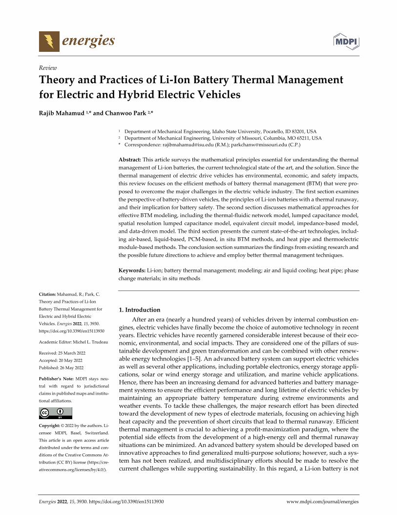
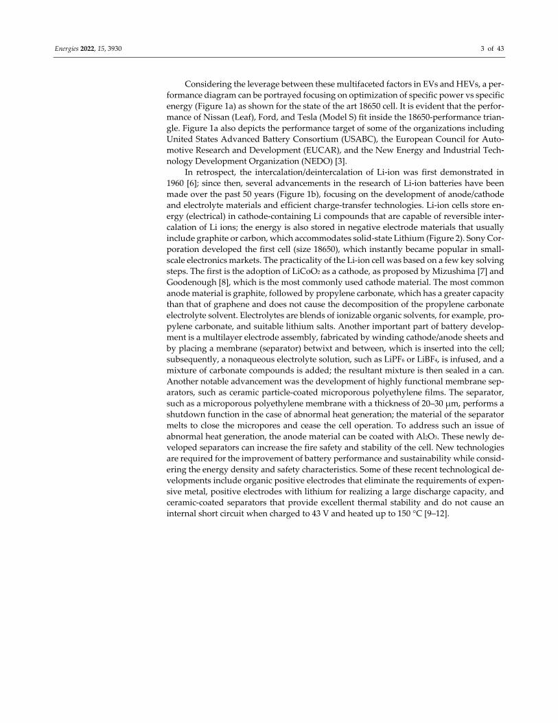
energy, power, weight, and volumetric requirements as envisioned in Figure 1a,b [3].
(a)
(b)
Figure 1. (a) EVs and 18650 cell power vs. energy for some commercially available cells under dif‐
ferent applications. Adapted with permission from [3]. Copyright 2003 Springer. (b) Increase in spe‐
cific energy of 18650 Li cell thanks to the development over the last 50 years when the intercala‐
tion/deintercalation of Li was shown. Adapted with permission from [3]. Copyright 2018 Springer.
Energies 2022, 15, 3930 3 of 43
Considering the leverage between these multifaceted factors in EVs and HEVs, a per‐
formance diagram can be portrayed focusing on optimization of specific power vs specific
energy (Figure 1a) as shown for the state of the art 18650 cell. It is evident that the perfor‐
mance of Nissan (Leaf), Ford, and Tesla (Model S) fit inside the 18650‐performance trian‐
gle. Figure 1a also depicts the performance target of some of the organizations including
United States Advanced Battery Consortium (USABC), the European Council for Auto‐
motive Research and Development (EUCAR), and the New Energy and Industrial Tech‐
nology Development Organization (NEDO) [3].
In retrospect, the intercalation/deintercalation of Li‐ion was first demonstrated in
1960 [6]; since then, several advancements in the research of Li‐ion batteries have been
made over the past 50 years (Figure 1b), focusing on the development of anode/cathode
and electrolyte materials and efficient charge‐transfer technologies. Li‐ion cells store en‐
ergy (electrical) in cathode‐containing Li compounds that are capable of reversible inter‐
calation of Li ions; the energy is also stored in negative electrode materials that usually
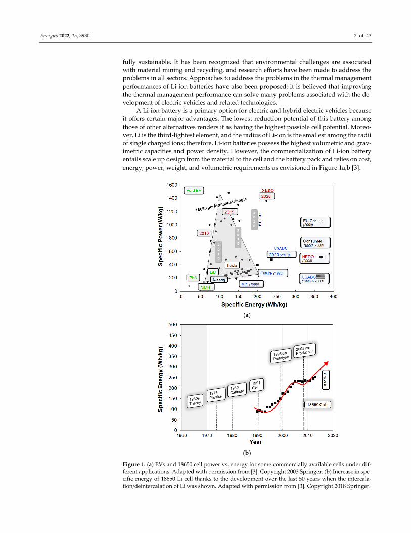
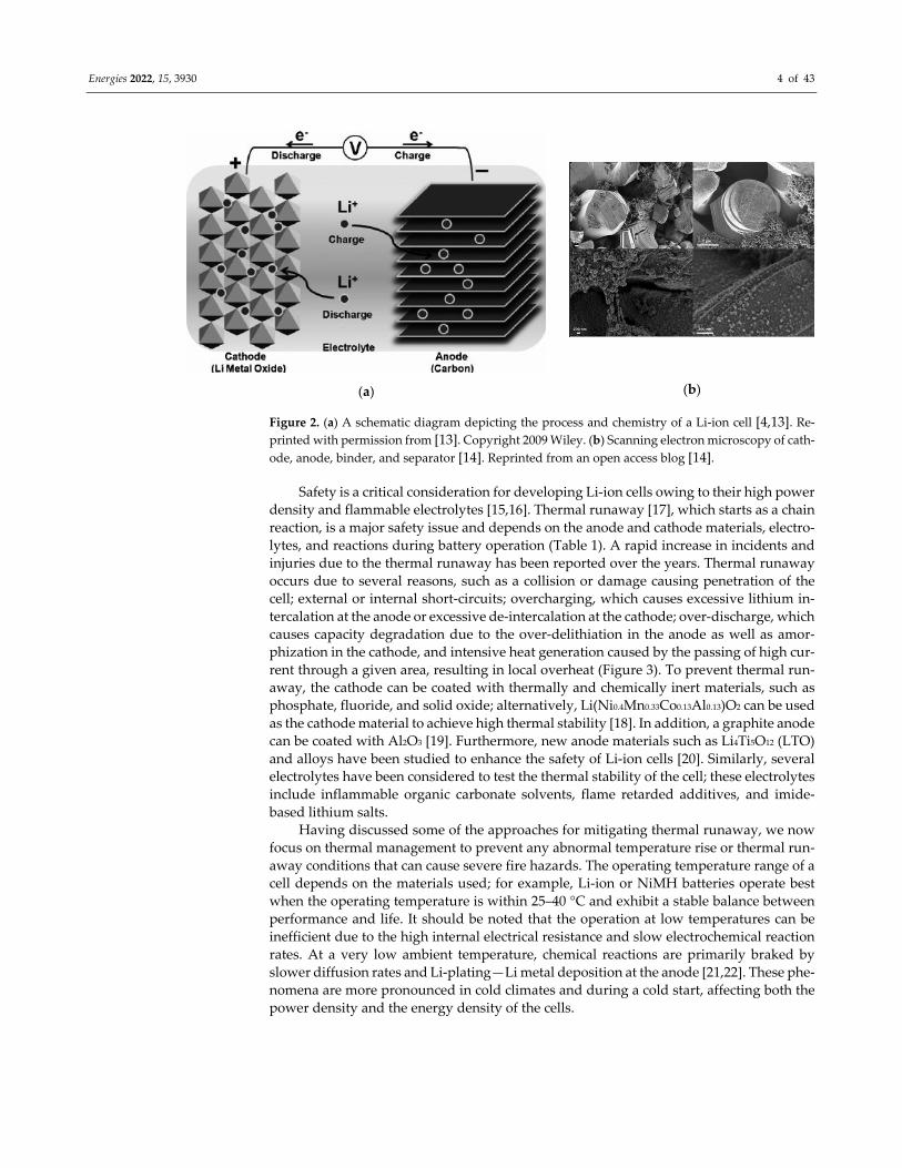
include graphite or carbon, which accommodates solid‐state Lithium (Figure 2). Sony Cor‐
poration developed the first cell (size 18650), which instantly became popular in small‐
scale electronics markets. The practicality of the Li‐ion cell was based on a few key solving
steps. The first is the adoption of LiCoO2 as a cathode, as proposed by Mizushima [7] and
Goodenough [8], which is the most commonly used cathode material. The most common
anode material is graphite, followed by propylene carbonate, which has a greater capacity
than that of graphene and does not cause the decomposition of the propylene carbonate
electrolyte solvent. Electrolytes are blends of ionizable organic solvents, for example, pro‐
pylene carbonate, and suitable lithium salts. Another important part of battery develop‐
ment is a multilayer electrode assembly, fabricated by winding cathode/anode sheets and
by placing a membrane (separator) betwixt and between, which is inserted into the cell;
subsequently, a nonaqueous electrolyte solution, such as LiPF6 or LiBF4, is infused, and a
mixture of carbonate compounds is added; the resultant mixture is then sealed in a can.
Another notable advancement was the development of highly functional membrane sep‐
arators, such as ceramic particle‐coated microporous polyethylene films. The separator,
such as a microporous polyethylene membrane with a thickness of 20–30 μm, performs a
shutdown function in the case of abnormal heat generation; the material of the separator
melts to close the micropores and cease the cell operation. To address such an issue of
abnormal heat generation, the anode material can be coated with Al2O3. These newly de‐
veloped separators can increase the fire safety and stability of the cell. New technologies
are required for the improvement of battery performance and sustainability while consid‐
ering the energy density and safety characteristics. Some of these recent technological de‐
velopments include organic positive electrodes that eliminate the requirements of expen‐
sive metal, positive electrodes with lithium for realizing a large discharge capacity, and
ceramic‐coated separators that provide excellent thermal stability and do not cause an
internal short circuit when charged to 43 V and heated up to 150 °C [9–12].
Energies 2022, 15, 3930 4 of 43
(a) (b)
Figure 2. (a) A schematic diagram depicting the process and chemistry of a Li‐ion cell [4,13]. Re‐
printed with permission from [13]. Copyright 2009 Wiley. (b) Scanning electron microscopy of cath‐
ode, anode, binder, and separator [14]. Reprinted from an open access blog [14].
Safety is a critical consideration for developing Li‐ion cells owing to their high power
density and flammable electrolytes [15,16]. Thermal runaway [17], which starts as a chain
reaction, is a major safety issue and depends on the anode and cathode materials, electro‐
lytes, and reactions during battery operation (Table 1). A rapid increase in incidents and
injuries due to the thermal runaway has been reported over the years. Thermal runaway
occurs due to several reasons, such as a collision or damage causing penetration of the
cell; external or internal short‐circuits; overcharging, which causes excessive lithium in‐
tercalation at the anode or excessive de‐intercalation at the cathode; over‐discharge, which
causes capacity degradation due to the over‐delithiation in the anode as well as amor‐
phization in the cathode, and intensive heat generation caused by the passing of high cur‐
rent through a given area, resulting in local overheat (Figure 3). To prevent thermal run‐
away, the cathode can be coated with thermally and chemically inert materials, such as
phosphate, fluoride, and solid oxide; alternatively, Li(Ni0.4Mn0.33Co0.13Al0.13)O2 can be used
as the cathode material to achieve high thermal stability [18]. In addition, a graphite anode
can be coated with Al2O3 [19]. Furthermore, new anode materials such as Li4Ti5O12 (LTO)
and alloys have been studied to enhance the safety of Li‐ion cells [20]. Similarly, several
electrolytes have been considered to test the thermal stability of the cell; these electrolytes
include inflammable organic carbonate solvents, flame retarded additives, and imide‐
based lithium salts.
Having discussed some of the approaches for mitigating thermal runaway, we now
focus on thermal management to prevent any abnormal temperature rise or thermal run‐
away conditions that can cause severe fire hazards. The operating temperature range of a
cell depends on the materials used; for example, Li‐ion or NiMH batteries operate best
when the operating temperature is within 25–40 °C and exhibit a stable balance between
performance and life. It should be noted that the operation at low temperatures can be
inefficient due to the high internal electrical resistance and slow electrochemical reaction
rates. At a very low ambient temperature, chemical reactions are primarily braked by
slower diffusion rates and Li‐plating—Li metal deposition at the anode [21,22]. These phe‐
nomena are more pronounced in cold climates and during a cold start, affecting both the
power density and the energy density of the cells.

Energies 2022, 15, 3930 5 of 43
Table 1. Reactions relevant to Li‐on battery thermal runaway [15,16].
Reactions Reaction Chemistry Temperature (°C)
SEI decomposition (CH2OCO2Li)2 Li2CO3 + C2H4 + CO2 + 0.5O2 90–120
Negative electrode/electrolyte
2Li +C3H4O3 (EC) Li2CO3 + C2H4
>100 2Li + C4H6O3 (PC) Li2CO3 + C3H6
2Li + C3H6O3 (DMC) Li2CO3 + C2H6
Separator meltdown ‐ ~130
Positive electrode decomposition
LixCoO2 xLiCO2 + 1/3 (1−x)CO3O4 + 1/3(1−x)O2
196–230 Co3O4 3CoO + 0.5O2
CoO Co + 0.5O2
Solvent/O2
2.5O2 + C3H4O3 (EC) 3CO2 + 2H2O 4O2 + C4H6O3 (PC) 4CO2 + 3H2O
3O2 + C3H6O3 (DMC) 3CO2 + 3H2O
Electrolyte decomposition LiPF6 LiF + PF5
200–300 C2H5OCOOPF4 PF3O + CO2 + C2H4 + HF
Positive electrode/electrolyte
2Li + 2EC Li‐O‐(CH2)4‐O‐Li + 2CO3
200–240 Li‐O‐(CH2)4‐O‐Li + PF5 Li‐O‐(CH2)4‐F + 2LiF +
POF3
Negative electrode/binder ‐CH2‐CF2 + Li LiF + ‐CH = CF‐ + 0.5 H2 >260
Reprinted with permission from [15]. Copyright 2012 Elsevier.
A battery pack contains an assembly of several series or parallelly connected cells,
and thermal instability in any of the cells can cause a chain reaction in the pack, resulting
in an explosion and fire. Thermal instability in any cell can be initiated by non‐uniform
cooling in the pack and non‐uniform heat generation in the cell, particularly at a higher
discharge current. In such cases, the heat generation in a cell varies significantly in the
radial (spiral) direction from the terminal (core) to the battery skin (surface). At higher
discharge currents, the current discharge is significantly higher in the terminal and lower
at the surface [23]. This condition resembles a high Biot number condition in a very large
cell, where the core temperature is significantly larger than the surface temperature.
Therefore, BTM is crucial to keep the cell temperature in an operational temperature range
and maintain a uniform temperature between cells, thus preventing them from locally
overheating. Conversely, cell performance at very low and subzero temperatures is de‐
graded by slower electrochemical responses and Li‐plating [24–26]. Thereby, thermal
management cannot be practically realized without both cooling and heating functions
depending on different weather conditions.
(a) (b)
Figure 3. (a) Qualitative interpretation of the chain reactions during thermal runaway. (b) Over‐
charge induced thermal runaway for a commercial lithium‐ion battery [27]. Adapted with permis‐
sion from [17,27]. Copyrights 2020 Elsevier.
Energies 2022, 15, 3930 6 of 43
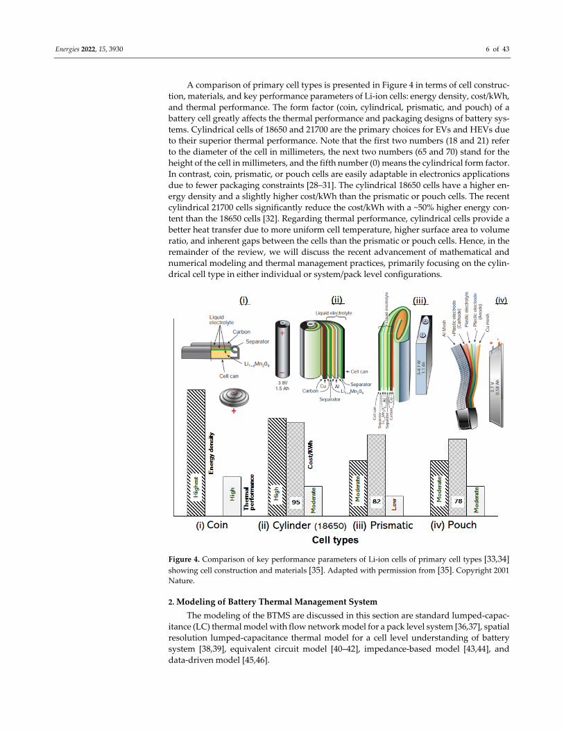
A comparison of primary cell types is presented in Figure 4 in terms of cell construc‐
tion, materials, and key performance parameters of Li‐ion cells: energy density, cost/kWh,
and thermal performance. The form factor (coin, cylindrical, prismatic, and pouch) of a
battery cell greatly affects the thermal performance and packaging designs of battery sys‐
tems. Cylindrical cells of 18650 and 21700 are the primary choices for EVs and HEVs due
to their superior thermal performance. Note that the first two numbers (18 and 21) refer
to the diameter of the cell in millimeters, the next two numbers (65 and 70) stand for the
height of the cell in millimeters, and the fifth number (0) means the cylindrical form factor.
In contrast, coin, prismatic, or pouch cells are easily adaptable in electronics applications
due to fewer packaging constraints [28–31]. The cylindrical 18650 cells have a higher en‐
ergy density and a slightly higher cost/kWh than the prismatic or pouch cells. The recent
cylindrical 21700 cells significantly reduce the cost/kWh with a ~50% higher energy con‐
tent than the 18650 cells [32]. Regarding thermal performance, cylindrical cells provide a
better heat transfer due to more uniform cell temperature, higher surface area to volume
ratio, and inherent gaps between the cells than the prismatic or pouch cells. Hence, in the
remainder of the review, we will discuss the recent advancement of mathematical and
numerical modeling and thermal management practices, primarily focusing on the cylin‐
drical cell type in either individual or system/pack level configurations.
Figure 4. Comparison of key performance parameters of Li‐ion cells of primary cell types [33,34]
showing cell construction and materials [35]. Adapted with permission from [35]. Copyright 2001 Nature.
2. Modeling of Battery Thermal Management System
The modeling of the BTMS are discussed in this section are standard lumped‐capac‐
itance (LC) thermal model with flow network model for a pack level system [36,37], spatial
resolution lumped‐capacitance thermal model for a cell level understanding of battery
system [38,39], equivalent circuit model [40–42], impedance‐based model [43,44], and
data‐driven model [45,46].
Energies 2022, 15, 3930 7 of 43
2.1. Lumped‐Capacitance Thermal Model and Flow Network Model
Li‐ion batteries come in two main form factors: prismatic and cylindrical. The cylin‐
drical type is more common than the prismatic type, and it is usually constructed in a
multilayer spiral structure assembled radially, resulting in a lower effective thermal con‐
ductivity that dominates heat conduction compared to axial conduction. However, the
thermal resistance due to the radial conduction is much less than convective thermal re‐
sistance; hence, the Biot number is significantly less than 1. Therefore, most numerical
studies have employed the standard lumped‐capacitance thermal model supposing an
even temperature in the cell from the core to the surface. This assumption allows using
transient thermal boundary conditions, simulating an actual duty cycle and real‐time bat‐
tery control, while reducing the computational load and time.
A test module comprising eight cells (yellow circles in Figure 5a) with symmetric
boundary conditions on both its sides was modeled using the LC thermal model and a
flow network model. Figure 5b,c depict the thermal circuit diagram of a cell and the eight‐
cell module [12].
Applying the first law of thermodynamics for an individual cell (index number i)
𝜌𝑐 𝑉 s,i𝑑𝑇s,i
𝑑𝑡𝑆r,i 𝑄ku,i (1)
where 𝑆r,i is the heat generation rate in a cell. The 𝑆r,i in a cell is modeled as the summa‐
tion of the (i) Joule (irreversible) and (ii) entropic (reversible) heats and is expressed by
𝑆r,i 𝑄 𝑄 (2)
where the Qirr is heat generation owing to the Joule heating corresponding to the intrinsic
electrical resistance 𝑅 and is written by
𝑄 𝐼 𝐸 𝐸 𝐼 𝑅 (3)
where 𝑅 is the internal electrical resistance of a cell and is comprehensively studied in
the literature for different types of cells. In the aforementioned expression, the contribu‐
tion of the electrode side reaction, such as corrosion and parasitic reactions are typically
ignored. Empirical correlations for 𝑅 are available as a function of SOC and temperature
or as an average of the state‐of‐charge (SOC) and temperatures and is written as [36,47]
𝑅 0.0001 𝑇 0.0134 𝑇 0.5345 𝑇 12.407 (4)
where 𝑅 is the internal electrical resistance in m and T is the cell temperature in °C.
Depending on cell types, empirical data are also available for different cell chemis‐
tries. For example, for a 2.2 Ah LiFePO4 cell, the electrical resistance was evaluated in
terms of average cell temperature and SOC [48] as below
𝑅 27.54 27.68 exp1.91𝑇
223.711 21.1 SOC
225.06 exp 1.91𝑇
1 21.61 SOC (5)
where T is the cell temperature in K and SOC is the estimated state of the charge. Likewise,
the electrical resistance was also evaluated in terms of the SOC for different cell tempera‐
tures for a cylindrical SONY‐US50G3 battery [49] as below
𝑅2.258 10 SOC . , 𝑇 293 K1.857 10 SOC . , 𝑇 303 K1.659 10 SOC . , 𝑇 313 K
(6)

Energies 2022, 15, 3930 8 of 43
Figure 5. (a) A schematic diagram of the eight‐cell thermal circuit, (b) single‐cell thermal circuit, and
(c) flow network model. Reprinted with permission from [36]. Copyrights 2011 Elsevier.
The electrical resistance varies with thermal or chemical non‐equilibrium, making it
a function of SOC and temperature [50]. It also depends strongly on the technique and
condition used for the estimation. Therefore, a predictable and reliable estimation of the
battery resistance is essential in designing and evaluating battery thermal management
[51]. Table 2 comprises some literature expressions of internal electrical resistance.
Table 2. Expressions of internal electrical resistance in the literature.
Cell Type Expression or Value Ref.
LiMn2O4
cylindrical 𝑅 0.0001 𝑇 0.0134 𝑇 0.5345 𝑇 12.407 [36]
2.2 Ah LiPePO4 cell
cylindrical 𝑅 27.54 27.68 exp
1.91𝑇
223.711 21.1 SOC
225.06 exp1.91𝑇
1 21.61 SOC [48]
SONY‐US50G3
cylindrical 𝑅
2.258 10 SOC . , 𝑇 293 K1.857 10 SOC . , 𝑇 303 K1.659 10 SOC . , 𝑇 313 K
[49]
1.25 Ah Sony 18650
cylindrical 𝑅 𝑓 DOD , 0.8– 1.8 [52]
20 Ah Lithium‐Ion Polymer
Battery
𝑅 0.035 0.1562 exp 24.74 SOC 𝑅 , 0.04669 0.3208 exp 29.14 SOC 𝑅 , 0.04984 6.604 exp 155.2 SOC
[53]
60 Ah prismatic battery 1.61 mΩ (charging) and 0.937 mΩ (discharging) [54]
Qrev, the second term in Equation (2), characterizes the reversible entropy loss and is
a function of the entropy coefficient dEoc/dT, charge density, SOC, and cell temperature
and is given by
𝑄 𝐼𝑇𝑑𝐸𝑑𝑇
(7)
Energies 2022, 15, 3930 9 of 43
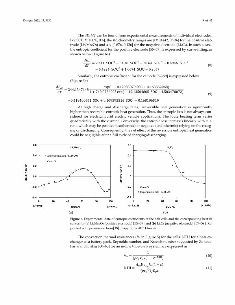
The dEoc/dT can be found from experimental measurements of individual electrodes.
For SOC ∊ [100%, 0%], the stoichiometry ranges are 𝑦 ∊ [0.442, 0.936] for the positive elec‐trode (LiyMn2O4) and 𝑥 ∊ [0.676, 0.126] for the negative electrode (LixC6). In such a case,
the entropic coefficient for the positive electrode [55–57] is expressed by curve‐fitting, as
shown below (Figure 6a)
𝑑𝐸𝑑𝑇
29.41 SOC 54.18 SOC 20.64 SOC 8.4946 SOC
5.4224 SOC 1.0674 SOC 0.2057 (8)
Similarly, the entropic coefficient for the cathode [57–59] is expressed below
(Figure 6b)
𝑑𝐸𝑑𝑇
344.1347148exp 18.12983079 SOC 4.163332068
1 749.0756003 exp 19.13504805 SOC 4.503478072
0.418400661 SOC 0.109595516 SOC 0.168196519
(9)
At high charge and discharge rates, irreversible heat generation is significantly
higher than reversible entropic heat generation. Thus, the entropic loss is not always con‐
sidered for electric/hybrid electric vehicle applications. The Joule heating term varies
quadratically with the current. Conversely, the entropic loss increases linearly with cur‐
rent, which may be positive (exothermic) or negative (endothermic) relying on the charg‐
ing or discharging. Consequently, the net effect of the reversible entropic heat generation
could be negligible after a full cycle of charging/discharging.
(a) (b)
Figure 6. Experimental data of entropic coefficients of the half cells and the corresponding best‐fit
curves for (a) LiyMn2O4 (positive electrode) [55–57] and (b) LixC6 (negative electrode) [57–59]. Re‐
printed with permission from[38]. Copyrights 2013 Elsevier.
The convection thermal resistances (Ru in Figure 5) for the cells, NTU for a heat ex‐
changer as a battery pack, Reynolds number, and Nusselt number suggested by Zukaus‐
kas and Ulinskas [60–63] for an in‐line tube‐bank system are expressed as
𝑅1
𝜌𝑐 𝑉 1 𝑒 NTU (10)
NTU𝐴kuNu 𝑘 1 𝜀
𝜌𝑐 𝑉 𝐷 𝜀 (11)

Energies 2022, 15, 3930 10 of 43
Re ,𝜌𝑢 𝐷
𝜇 (12)
Nu
⎩⎪⎪⎪⎪⎪⎨
⎪⎪⎪⎪⎪⎧ 0.8 Re ,max
. Pr . Pr
Pr
.
, 10 Re , 10
0.51 Re ,max . Pr .
PrPr
.
, 10 Re , 10
0.27 Re ,max . Pr .
PrPr
.
, 10 Re , 2 10
0.021 Re ,max . Pr .
PrPr
.
, 2 10 Re , 2 10
(13)
The energy conservation equation for the coolant flow over a battery cell is given as
𝑄u,i 𝑄u,i 𝑄ku,i 0 (14)
𝑄u,i 𝑄u,i 𝜌𝑐 𝑉 𝑇f,i 𝑇f,i (15)
Here, umax is the maximum flow velocity between the cells. The Nusselt number in
Equation (13) is valid only when the number of the cells in the streamwise direction ex‐
ceeds 20. For the eight‐cell system used for this study, a correction factor, C2 = 0.95, is
required to correct the Nusselt number in Equation (13), i.e., C2 NuD.
2.2. Spatial‐Resolution Lumped‐Capacitance Thermal Model
It is a common practice to perform the model‐based design, both for cylindrical and
prismatic cells, using CFD (computational fluid dynamics) approaches, which provide an
accurate description of core temperature and time‐dependent thermophysical properties
and electrical properties. The estimation of core temperature is of much importance,
which is sufficiently higher than the surface and average temperature, as estimated by the
classical lumped thermal model. However, the CFD modeling has been numerically ex‐
pensive and computationally not efficient for a fast calculation. In this section, we discuss
a spatial resolution lumped thermal model that calculates the core temperature of the cell
in a time‐efficient manner.
The governing equations based on a cylindrical cell (Figure 7) approximation can be
written as
𝜌 𝑇 𝑐 , 𝑇𝜕𝑇𝜕𝑡
1𝑟𝜕𝜕𝑟
𝑟𝑘 𝑇𝜕𝑇𝜕𝑟
𝑠 𝑟, 𝑡 for 0 𝑟 𝑅 and 𝑡 0 (16)
𝑘 𝑇𝜕𝑇 𝑅, 𝑡𝜕𝑟
ℎ 𝑡 𝑇 𝑅, 𝑡 𝑇∞ 𝑡 for 𝑡 0 (17)
𝜕𝑇 0, 𝑡𝜕𝑟
0 for 𝑡 0 (18)
𝑇 𝑟, 0 𝑇 𝑟 for 0 𝑟 𝑅 (19)
where s(r,t) is the volumetric heat generation of a cell.
From an individual cell level consideration, it is rational to assume that the cell is
subjected to a uniform temperature and convective heat transfer coefficient at the cell
level. Consequently, for a pack with multiple cells, the cell level model can be extended
using a flow network model where the ambient temperature will be updated along with
the cell as discussed in Section 2.1. In electric vehicles, the coolant air inducts from the
cabin air, providing easy access and reliability; although, it has a low convective heat
transfer capacity.

Energies 2022, 15, 3930 11 of 43
(a) (b)
Figure 7. (a) A typical configuration of the spiral and multilayer structure of a standard cylindrical
cell [6] and (b) the realistic prediction of cell temperature depends on the actual description of the
time‐dependent thermal boundary conditions. Reprinted with permission from [38]. Copyright 2013 Elsevier.
The flow network model in Section 2.1 is based on a conventional LC thermal model
and assumes a uniform cell temperature that applies to a low Biot number (i.e., Bi
0.1). Conversely, recent advances in high power density and energy density cells require
highly efficient cooling mechanisms, such as liquid cooling, where the convective heat
transfer coefficient could reach 100 times that of conventional (air cooling). Moreover,
larger cells becoming more popular in several applications. Such conditions could result
from Bi > 0.1 and can result in a larger temperature gradient within the cell with increasing
temperature from the surface to the core of the cell. In such cases, the improved lumped
thermal model could be applied to correctly estimate battery core temperature [13]. The
mathematical formulations of these problems under high Biot number conditions are de‐
scribed in this section [13].
The improved lumped thermal model (spatial resolution LC thermal model) can es‐
timate the core temperature, average cell temperature, and skin (surface) temperature of
an individual cell. By definition, the area integrated average cell temperature is called the
area‐averaged cell temperature. In Figure 7b, it can be written by
𝑇 𝑡1𝜋𝑅
2𝜋𝑟 𝑇 𝑟, 𝑡 𝑑𝑟 (20)
Hence, the temporal variation in the 𝑇 𝑡 (average temperature) can be written as
𝑑𝑇 𝑡𝑑𝑡
1𝜋𝑅
2𝜋𝑟𝜕𝑇 𝑟, 𝑡𝜕𝑡
𝑑𝑟 (21)
Equation (16) can be integrated (with respect to r variable) and then combined with
the boundary conditions [Equations (16) and (17)] and averaged temperature [Equation
(21)] to obtain the following governing equation,
𝜌 𝑇 𝑐 , 𝑇𝑑𝑇 𝑡
𝑑𝑡2ℎ 𝑡𝑅
𝑇 𝑅, 𝑡 𝑇∞ 𝑡 𝑠 𝑡 (22)
It can be seen that Equation (22) counts both surface and average temperatures [i.e.,
𝑇 𝑡 and 𝑇 𝑅, 𝑡 ] in comparison to the formulation of the classical LC model.
The equivalent equation of Equation (22) for the conventional LC thermal model
takes that the temperature gradient is significantly small when Bi < 0.1, i.e., 𝑇 𝑅, 𝑡
Energies 2022, 15, 3930 12 of 43
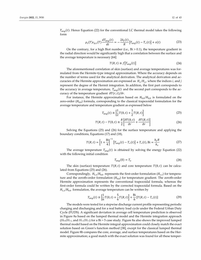
𝑇 𝑡 . Hence Equation (22) for the conventional LC thermal model takes the following
form
𝜌 𝑇 𝑐 , 𝑇𝑑𝑇 𝑡
𝑑𝑡2ℎ 𝑡𝑅
𝑇 𝑡 𝑇∞ 𝑡 𝑠 𝑡 (23)
On the contrary, for a high Biot number (i.e., Bi > 0.1), the temperature gradient in
the radial direction would be significantly high that a correlation between the surface and
the average temperature is necessary [64]
𝑇 𝑅, 𝑡 ≅ 𝑓 𝑇 𝑡 (24)
The aforementioned correlation of skin (surface) and average temperatures was for‐
mulated from the Hermite‐type integral approximation. Where the accuracy depends on
the number of terms used for the analytical derivation. The analytical derivation and ac‐
curacies of the Hermite approximation are expressed as 𝐻i,i/𝐻j,j, where the indices i, and j
represent the degree of the Hermit integration. In addition, the first part corresponds to
the accuracy in average temperature, 𝑇 𝑡 and the second part corresponds to the ac‐curacy of the temperature gradient 𝜕𝑇 𝑟, 𝑡 /𝜕𝑟.
For instance, the Hermite approximation based on 𝐻 , /𝐻 , is formulated on the
zero‐order (𝐻 , ) formula, corresponding to the classical trapezoidal formulation for the
average temperature and temperature gradient as expressed below
𝑇 𝑡 ≅12𝑇 0, 𝑡
12𝑇 𝑅, 𝑡 (25)
𝑇 𝑅, 𝑡 𝑇 0, 𝑡 ≅𝑅2𝜕𝑇 0, 𝑡𝜕𝑟
𝜕𝑇 𝑅, 𝑡𝜕𝑟
(26)
Solving the Equations (25) and (26) for the surface temperature and applying the
boundary conditions, Equations (17) and (18),
𝑇 𝑅, 𝑡 1Bi4
𝑇 𝑡 𝑇∞ 𝑡 𝑇∞ 𝑡 , Biℎ 𝑅𝑘 (27)
The average temperature 𝑇 𝑡 is obtained by solving the energy Equation (22) with the following initial condition
𝑇 0 𝑇 (28)
The skin (surface) temperature 𝑇 𝑅, 𝑡 and core temperature 𝑇 0, 𝑡 can be calcu‐lated from Equations (25) and (26).
Correspondingly, 𝐻 , /𝐻 , represents the first‐order formulation (𝐻 , ) for tempera‐
ture and the zeroth‐order formulation (𝐻 , ) for temperature gradient. The zeroth‐order
Hermite approximation represents the conventional trapezoidal formula, whereas the
first‐order formula could be written by the corrected trapezoidal formula. Based on the
𝐻 , /𝐻 , formulation, the average temperature can be written by
𝑇 𝑡 ≅16𝑇 0, 𝑡
56𝑇 𝑅, 𝑡
Bi
6𝑇 𝑅, 𝑡 𝑇∞ 𝑡 (29)
The models were tested for a stepwise discharge current profile representing periodic
charging and discharging and for a real battery load cycle under the Federal Urban Duty
Cycle (FUDS). A significant deviation in average cell temperature prediction is observed
in Figure 8a based on the lumped thermal model and the Hermite integration approach
(H0,0/H1,1, and H1,1/H1,1) for a Bi = 5 case study. Figure 8a also shows the improved lumped
thermal model based on the Hermite integral approximation could closely match the exact
solution based on Green’s function method [38], except for the classical lumped thermal
model. Figure 8b compares the core, average, and surface temperatures based on the Her‐
mite approximation; a good match with the exact solution was found for all these temper‐
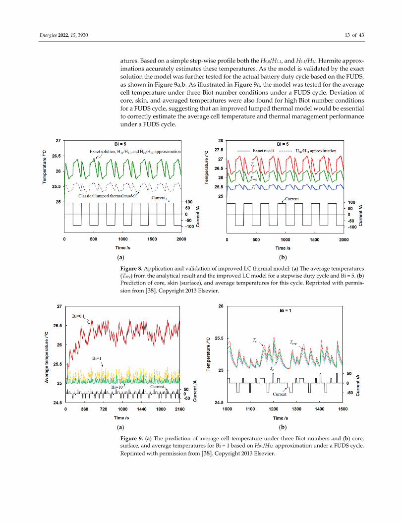
Energies 2022, 15, 3930 13 of 43
atures. Based on a simple step‐wise profile both the H0,0/H1,1, and H1,1/H1,1 Hermite approx‐
imations accurately estimates these temperatures. As the model is validated by the exact
solution the model was further tested for the actual battery duty cycle based on the FUDS,
as shown in Figure 9a,b. As illustrated in Figure 9a, the model was tested for the average
cell temperature under three Biot number conditions under a FUDS cycle. Deviation of
core, skin, and averaged temperatures were also found for high Biot number conditions
for a FUDS cycle, suggesting that an improved lumped thermal model would be essential
to correctly estimate the average cell temperature and thermal management performance
under a FUDS cycle.
(a) (b)
Figure 8. Application and validation of improved LC thermal model: (a) The average temperatures
(Tavg) from the analytical result and the improved LC model for a stepwise duty cycle and Bi = 5. (b)
Prediction of core, skin (surface), and average temperatures for this cycle. Reprinted with permis‐
sion from [38]. Copyright 2013 Elsevier.
(a) (b)
Figure 9. (a) The prediction of average cell temperature under three Biot numbers and (b) core,
surface, and average temperatures for Bi = 1 based on H0,0/H1,1 approximation under a FUDS cycle.
Reprinted with permission from [38]. Copyright 2013 Elsevier.
Energies 2022, 15, 3930 14 of 43
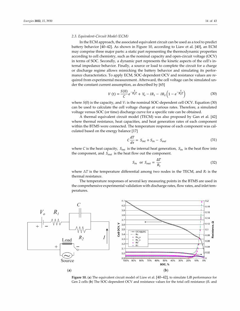
2.3. Equivalent‐Circuit Model (ECM)
In the ECM approach, the associated equivalent circuit can be used as a tool to predict
battery behavior [40–42]. As shown in Figure 10, according to Liaw et al. [40], an ECM
may comprise three major parts: a static part representing the thermodynamic properties
according to cell chemistry, such as the nominal capacity and open‐circuit voltage (OCV)
in terms of SOC. Secondly, a dynamic part represents the kinetic aspects of the cell’s in‐
ternal impedance behavior. Finally, a source or load to complete the circuit for a charge
or discharge regime allows mimicking the battery behavior and simulating its perfor‐
mance characteristics. To apply ECM, SOC‐dependent OCV and resistance values are re‐
quired from experimental measurement. Afterward, the cell voltage can be simulated un‐
der the constant current assumption, as described by [65]
𝑉 t𝑆 0𝐶
𝑒 𝑉 𝐼𝑅 𝐼𝑅 1 𝑒 (30)
where S(0) is the capacity, and Vo is the nominal SOC‐dependent cell OCV. Equation (30)
can be used to calculate the cell voltage change at various rates. Therefore, a simulated
voltage versus SOC (or time) discharge curve for a specific rate can be obtained.
A thermal equivalent circuit model (TECM) was also proposed by Gan et al. [42]
where thermal resistance, heat capacities, and heat generation rates of each component
within the BTMS were connected. The temperature response of each component was cal‐
culated based on the energy balance [17]
𝐶𝑑𝑇𝑑𝜏
𝑆 𝑆 𝑆 (31)
where C is the heat capacity, 𝑆 is the internal heat generation, 𝑆 is the heat flow into
the component, and 𝑆 is the heat flow out the component.
𝑆 or 𝑆 ∆𝑇𝑅 (32)
where ΔT is the temperature differential among two nodes in the TECM, and Rt is the
thermal resistance.
The temperature responses of several key measuring points in the BTMS are used in
the comprehensive experimental validation with discharge rates, flow rates, and inlet tem‐
peratures.
(a) (b)
Figure 10. (a) The equivalent circuit model of Liaw et al. [40–42], to simulate LiB performance for
Gen 2 cells (b) The SOC‐dependent OCV and resistance values for the total cell resistance (Rc and
Energies 2022, 15, 3930 15 of 43
the two independent contributions Rco and Rcs), R1, and R2 of the Gen 2 chemistry in the model.
Adapted with permission from [40]. Copyright 2014 Elsevier.
Similarly, an electro‐thermal model was discussed by Lin et al. [66] comprising an
electrical model and a two temperatures model. These two parts were coupled through
SOC, current I, and electrical parameters. The coupled electro‐thermal model was able to
capture the core cell temperature as validated by the experiment.
In the model, the terminal voltage 𝑉 is was modeled as follows,
𝑉 𝑉 𝐼𝑅 𝑉 , (33)
In Equation (34), VOCV refers to open‐circuit voltage and depends on SOC, 𝐼 is the discharge current, and Rs is the ohmic resistance. 𝐼𝑅 refers to a voltage drop across the resistor and VRC refers to a voltage drop across a parallel RC circuit.
The ∑ term refers to a series of parallel RC circuits. The transient voltage profile of
an individual RC element can be formulated by
𝑑𝑉 ,
𝑑𝑡1
𝑅 𝐶 𝑉 ,
1 𝐶𝐼 (34)
The model solved for two temperatures (core and surface) from two governing equa‐
tions by assuming a longitudinal homogeneity as below
𝐶𝑑𝑇𝑑𝜏
𝑆𝑇 𝑇𝑅
(35)
𝐶𝑑𝑇𝑑𝜏
𝑇 𝑇𝑅
𝑇 𝑇𝑅
(36)
where 𝐶 is the heat capacity of the cell materials, 𝐶 is the heat capacity of the can, and 𝑆 in Equation (36) can be evaluated as follows
𝑆 𝐼 𝑉 𝑉 (37)
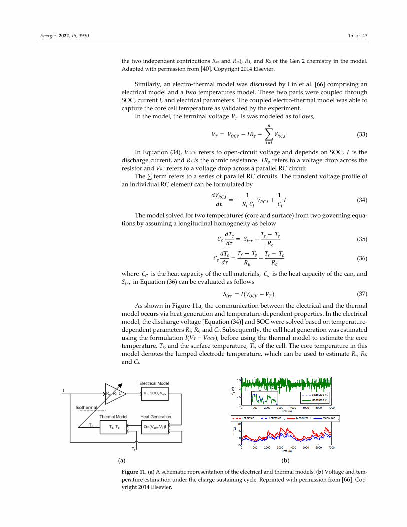
As shown in Figure 11a, the communication between the electrical and the thermal
model occurs via heat generation and temperature‐dependent properties. In the electrical
model, the discharge voltage [Equation (34)] and SOC were solved based on temperature‐
dependent parameters Rs, Ri, and Ci. Subsequently, the cell heat generation was estimated
using the formulation I(VT − VOCV), before using the thermal model to estimate the core
temperature, Tc, and the surface temperature, Ts, of the cell. The core temperature in this
model denotes the lumped electrode temperature, which can be used to estimate Rs, Ri,
and Ci.
(a) (b)
Figure 11. (a) A schematic representation of the electrical and thermal models. (b) Voltage and tem‐
perature estimation under the charge‐sustaining cycle. Reprinted with permission from [66]. Cop‐yright 2014 Elsevier.
Energies 2022, 15, 3930 16 of 43
The voltage, as well as temperatures predicted with the model, are shown in Figure
11b. The major advantages of this approach were the two‐temperature model and the es‐
timation of the core or lumped electrode temperature. This provides an added benefit in
precisely estimating temperature‐dependent Rs, Ri, and Ci of the electrical model and sub‐
sequently calculating the discharge voltage. This method could be significantly beneficial
under two scenarios, where a large temperature gradient is present within the cell volume,
such as a high Biot number condition and high current application. A combined battery
thermal management system of such a coupled electro‐thermal model is depicted in Fig‐
ure 12 [67,68].
Figure 12. Schematic illustration of the multi‐node and coupled electro‐thermal concept. Reprinted
with permission from [67]. Copyright 2020 Elsevier.
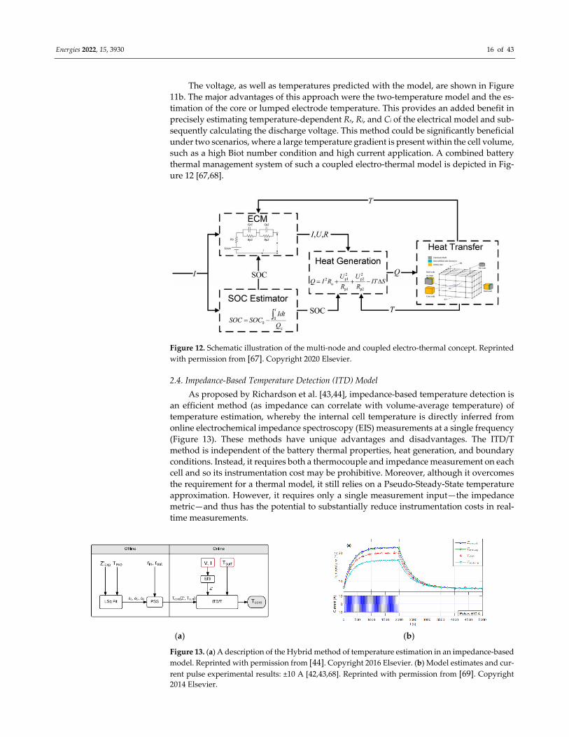
2.4. Impedance‐Based Temperature Detection (ITD) Model
As proposed by Richardson et al. [43,44], impedance‐based temperature detection is
an efficient method (as impedance can correlate with volume‐average temperature) of
temperature estimation, whereby the internal cell temperature is directly inferred from
online electrochemical impedance spectroscopy (EIS) measurements at a single frequency
(Figure 13). These methods have unique advantages and disadvantages. The ITD/T
method is independent of the battery thermal properties, heat generation, and boundary
conditions. Instead, it requires both a thermocouple and impedance measurement on each
cell and so its instrumentation cost may be prohibitive. Moreover, although it overcomes
the requirement for a thermal model, it still relies on a Pseudo‐Steady‐State temperature
approximation. However, it requires only a single measurement input—the impedance
metric—and thus has the potential to substantially reduce instrumentation costs in real‐
time measurements.
(a) (b)
Figure 13. (a) A description of the Hybrid method of temperature estimation in an impedance‐based
model. Reprinted with permission from [44]. Copyright 2016 Elsevier. (b) Model estimates and cur‐
rent pulse experimental results: ±10 A [42,43,68]. Reprinted with permission from [69]. Copyright 2014 Elsevier.
Energies 2022, 15, 3930 17 of 43
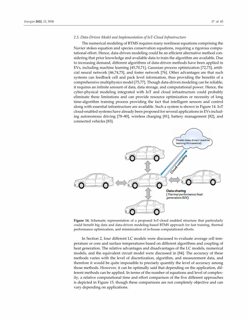
2.5. Data‐Driven Model and Implementation of IoT‐Cloud Infrastructure
The numerical modeling of BTMS requires many nonlinear equations comprising the
Navier stokes equation and species conservation equations, requiring a rigorous compu‐
tational effort. Hence, data‐driven modeling could be an efficient alternative method con‐
sidering that prior knowledge and available data to train the algorithm are available. Due
to increasing demand, different algorithms of data‐driven methods have been applied in
EVs, including machine learning [45,70,71], Gaussian process optimization [72,73], artifi‐
cial neural network [46,74,75], and foster network [76]. Other advantages are that such
systems can feedback cell and pack level information, thus providing the benefits of a
comprehensive multiphysics model [75,77]. Though data‐driven modeling can be reliable,
it requires an infinite amount of data, data storage, and computational power. Hence, the
cyber‐physical modeling integrated with IoT and cloud infrastructure could probably
eliminate these limitations and can provide resource optimization or necessity of long
time‐algorithm training process providing the fact that intelligent sensors and control
along with essential infrastructure are available. Such a system is shown in Figure 14. IoT
cloud‐enabled systems have already been proposed for several applications in EVs includ‐
ing autonomous driving [78–80], wireless charging [81], battery management [82], and
connected vehicles [83].
Figure 14. Schematic representation of a proposed IoT‐cloud enabled structure that particularly
could benefit big data and data‐driven modeling‐based BTMS approach for fast training, thermal
performance optimization, and minimization of in‐house computational efforts.
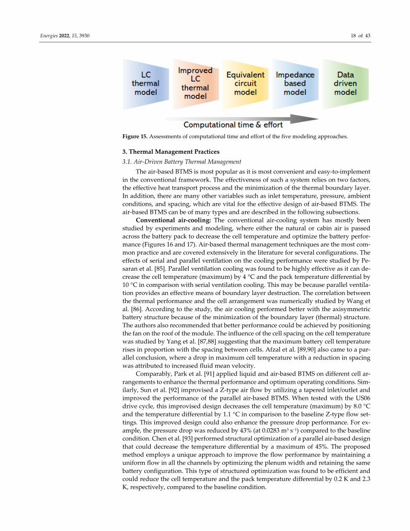
In Section 2, four different LC models were discussed to evaluate average cell tem‐
perature or core and surface temperatures based on different algorithms and coupling of
heat generation. The relative advantages and disadvantages of the LC models, numerical
models, and the equivalent circuit model were discussed in [84]. The accuracy of these
methods varies with the level of discretization, algorithm, and measurement data, and
therefore it would be quite impossible to precisely quantify the level of accuracy among
those methods. However, it can be optimally said that depending on the application, dif‐
ferent methods can be applied. In terms of the number of equations and level of complex‐
ity, a relative computational time and effort comparison of the five different approaches
is depicted in Figure 15, though these comparisons are not completely objective and can
vary depending on applications.
Energies 2022, 15, 3930 18 of 43
Figure 15. Assessments of computational time and effort of the five modeling approaches.
3. Thermal Management Practices
3.1. Air‐Driven Battery Thermal Management
The air‐based BTMS is most popular as it is most convenient and easy‐to‐implement
in the conventional framework. The effectiveness of such a system relies on two factors,
the effective heat transport process and the minimization of the thermal boundary layer.
In addition, there are many other variables such as inlet temperature, pressure, ambient
conditions, and spacing, which are vital for the effective design of air‐based BTMS. The
air‐based BTMS can be of many types and are described in the following subsections.
Conventional air‐cooling: The conventional air‐cooling system has mostly been
studied by experiments and modeling, where either the natural or cabin air is passed
across the battery pack to decrease the cell temperature and optimize the battery perfor‐
mance (Figures 16 and 17). Air‐based thermal management techniques are the most com‐
mon practice and are covered extensively in the literature for several configurations. The
effects of serial and parallel ventilation on the cooling performance were studied by Pe‐
saran et al. [85]. Parallel ventilation cooling was found to be highly effective as it can de‐
crease the cell temperature (maximum) by 4 °C and the pack temperature differential by
10 °C in comparison with serial ventilation cooling. This may be because parallel ventila‐
tion provides an effective means of boundary layer destruction. The correlation between
the thermal performance and the cell arrangement was numerically studied by Wang et
al. [86]. According to the study, the air cooling performed better with the axisymmetric
battery structure because of the minimization of the boundary layer (thermal) structure.
The authors also recommended that better performance could be achieved by positioning
the fan on the roof of the module. The influence of the cell spacing on the cell temperature
was studied by Yang et al. [87,88] suggesting that the maximum battery cell temperature
rises in proportion with the spacing between cells. Afzal et al. [89,90] also came to a par‐
allel conclusion, where a drop in maximum cell temperature with a reduction in spacing
was attributed to increased fluid mean velocity.
Comparably, Park et al. [91] applied liquid and air‐based BTMS on different cell ar‐
rangements to enhance the thermal performance and optimum operating conditions. Sim‐
ilarly, Sun et al. [92] improvised a Z‐type air flow by utilizing a tapered inlet/outlet and
improved the performance of the parallel air‐based BTMS. When tested with the US06
drive cycle, this improvised design decreases the cell temperature (maximum) by 8.0 °C
and the temperature differential by 1.1 °C in comparison to the baseline Z‐type flow set‐
tings. This improved design could also enhance the pressure drop performance. For ex‐
ample, the pressure drop was reduced by 43% (at 0.0283 m3 s−1) compared to the baseline
condition. Chen et al. [93] performed structural optimization of a parallel air‐based design
that could decrease the temperature differential by a maximum of 45%. The proposed
method employs a unique approach to improve the flow performance by maintaining a
uniform flow in all the channels by optimizing the plenum width and retaining the same
battery configuration. This type of structured optimization was found to be efficient and
could reduce the cell temperature and the pack temperature differential by 0.2 K and 2.3
K, respectively, compared to the baseline condition.

Energies 2022, 15, 3930 19 of 43
Jiaqiang et al. [94] performed a CFD simulation and evaluated the cooling perfor‐
mance depending on the arrangement of the inlet and outlet duct. Placing the inlet and
outlet on opposite walls was found to be more efficient than placing them on the same
side. As this enhances the mechanism of mixing and boundary layer destruction, posi‐
tioning the inlet/outlet ducts on the counter side can improve the temperature uniformity
in the battery pack. They also achieved a higher thermal performance by using baffle
plates in the flow channel, which enhanced flow mixing. Shahid et al. [95] introduced an
inlet plenum to achieve a higher thermal performance in a pack containing 32 cells. Based
on this configuration, the cell temperature and temperature nonuniformity could shrink
by the order of 18.3% and 54.6%, respectively. However, the proposed inlet plenum did
not significantly enhance the performance above the critical Reynolds number (7440).
Hong et al. [96] applied an additional outlet in air‐based BTMS and decreased the maxi‐
mum cell temperature by a minimum of 5 K. The application of a second vent also reduced
the temperature differential by 60% as compared with a system with no vent. Addition‐
ally, the thermal performance could be further enhanced by increasing the width of the
secondary vent.
Figure 16. Air‐based thermal management, as one of the most convenient forms of techniques, can
be optimized using a different configuration of the cooling channel [(a) Z, (b) U, or (c) J type] [16,97].
Reprinted with permission from [97] . Copyright 2021 Elsevier.
Energies 2022, 15, 3930 20 of 43
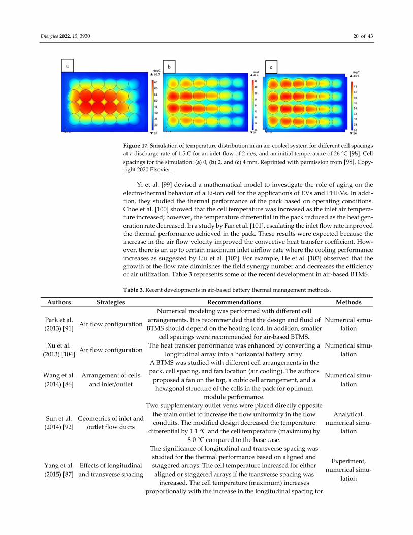
Figure 17. Simulation of temperature distribution in an air‐cooled system for different cell spacings
at a discharge rate of 1.5 C for an inlet flow of 2 m/s, and an initial temperature of 26 °C [98]. Cell
spacings for the simulation: (a) 0, (b) 2, and (c) 4 mm. Reprinted with permission from [98]. Copy‐right 2020 Elsevier.
Yi et al. [99] devised a mathematical model to investigate the role of aging on the
electro‐thermal behavior of a Li‐ion cell for the applications of EVs and PHEVs. In addi‐
tion, they studied the thermal performance of the pack based on operating conditions.
Choe et al. [100] showed that the cell temperature was increased as the inlet air tempera‐
ture increased; however, the temperature differential in the pack reduced as the heat gen‐
eration rate decreased. In a study by Fan et al. [101], escalating the inlet flow rate improved
the thermal performance achieved in the pack. These results were expected because the
increase in the air flow velocity improved the convective heat transfer coefficient. How‐
ever, there is an up to certain maximum inlet airflow rate where the cooling performance
increases as suggested by Liu et al. [102]. For example, He et al. [103] observed that the
growth of the flow rate diminishes the field synergy number and decreases the efficiency
of air utilization. Table 3 represents some of the recent development in air‐based BTMS.
Table 3. Recent developments in air‐based battery thermal management methods.
Authors Strategies Recommendations Methods
Park et al.
(2013) [91] Air flow configuration
Numerical modeling was performed with different cell
arrangements. It is recommended that the design and fluid of
BTMS should depend on the heating load. In addition, smaller
cell spacings were recommended for air‐based BTMS.
Numerical simu‐
lation
Xu et al.
(2013) [104] Air flow configuration
The heat transfer performance was enhanced by converting a
longitudinal array into a horizontal battery array.
Numerical simu‐
lation
Wang et al.
(2014) [86]
Arrangement of cells
and inlet/outlet
A BTMS was studied with different cell arrangements in the
pack, cell spacing, and fan location (air cooling). The authors
proposed a fan on the top, a cubic cell arrangement, and a
hexagonal structure of the cells in the pack for optimum
module performance.
Numerical simu‐
lation
Sun et al.
(2014) [92]
Geometries of inlet and
outlet flow ducts
Two supplementary outlet vents were placed directly opposite
the main outlet to increase the flow uniformity in the flow
conduits. The modified design decreased the temperature
differential by 1.1 °C and the cell temperature (maximum) by
8.0 °C compared to the base case.
Analytical,
numerical simu‐
lation
Yang et al.
(2015) [87]
Effects of longitudinal
and transverse spacing
The significance of longitudinal and transverse spacing was
studied for the thermal performance based on aligned and
staggered arrays. The cell temperature increased for either
aligned or staggered arrays if the transverse spacing was
increased. The cell temperature (maximum) increases
proportionally with the increase in the longitudinal spacing for
Experiment,
numerical simu‐
lation
Energies 2022, 15, 3930 21 of 43
staggered configurations and inversely proportional for aligned
arrays.
Wang et al.
(2015)
[105]
Impact of ambient tem‐
peratures, discharge
rates, and cooling con‐
ditions
The optimum operating air temperature range was proposed as
20–35 °C. However, when the air temperature is within 35–40
°C, an increment of flow velocity by 1 m/s was suggested.
However, no forced convection cooling was indicated when the
ambient temperature dropped below 20 °C.
Numerical simu‐
lation
Saw et al.
(2015) [106]
Effects of various mass
flow rates to predict a
correlation between the
Nu and Re
A new method of improving the thermal performance was
proposed based on numerically derived Nu vs. Re correlation
by conducting steady simulations at different flow rates and
studying them for different charging conditions. The proposed
method provides an efficient solution for large‐scale systems.
Numerical simu‐
lation
Erb et al.
(2017) [107]
Optimization of the cell
size to minimize the
cost of the blower
An analytical method was applied to optimize the cell size in a
pack. The optimum cell size can enhance thermal performance
and reduce pressure drops. The authors also indicated that the
blower cost could be doubled or tripled if the cell was not
optimized (cell‐wise, either larger or smaller).
Analytical
Shahid et al.
(2018)
[95,108]
Improvement of mix‐
ing and turbulence
Passive cooling (based on forced air) was used to generate
mixing and turbulence in the coolant and increase the
temperature homogeneity in the pack. The proposed design
reduced the cell temperature (maximum) by ~4% and enhance
the temperature homogeneity by ~39%.
Numerical simu‐
lation
Jiaqiang et
al. (2018)
[94]
Baffles and different ar‐
rangements of in‐
let/outlet
Placing the inlet and outlet on opposite edges was found to be
more efficient than if they were placed on the same side. The
authors also achieved a higher thermal performance by using
baffle plates in the flow channel, which enhanced flow mixing.
Numerical simu‐
lation
Na et al.
(2018) [109]
Multi‐layered flow
channel by the parti‐
tions (reversed layer
flow).
A method of reversed layer flow was proposed to enhance the
temperature homogeneity. The proposed method could reduce
the temperature differential by 1.1 °C compared to the
unidirectional flow. Further improvement was achieved by
adding rectifier grids during air ingress; this initiated
turbulence mixing at the entrance, reducing the maximum
temperature by ~0.5 °C and the temperature differential by ~0.6
°C (54.5% reduction).
Experiment,
numerical simu‐
lation
Hong et al.
(2018) [96]
Application of a sec‐
ondary vent
An optimally designed and placed secondary vent could
significantly enhance the thermal performance of the pack.
Applying this method decreased the maximum cell
temperature by at least 5 K and the pack temperature
differential by at least 60%.
Mathematical
analyses
Chen et al.
(2019) [110]
Optimization of cell
spacing
Compared to the typical BTMS, the maximum temperature for
the optimized BTMS was reduced by ~4 K, whereas the pack
temperature differential could be decreased by at least 69%
even when the flow rate is different.
Numerical simu‐
lation
Fan et al.
(2019) [101]
Arrangement of cells
(aligned, staggered,
and crosses)
The aligned arrangement had the best cooling performance and
temperature homogeneity, followed by the staggered and lastly
the cross arrangement; however, the aligned arrangement had
the lowest power consumption, up to 23% less than that of the
cross arrangement.
Numerical simu‐
lation
Peng et al.
(2019) [111]
Thermal inconsistency,
inlet/outlet configura‐
tions, and cell spacing
An alternative approach to inlet and outlet vent arrangement
(both on the same side) was proposed. The authors
recommended that the height of the inlet duct played a
Numerical simu‐
lation
Energies 2022, 15, 3930 22 of 43
significant role in the cell temperature and pack temperature
differential reduction, reducing sensitivity to the height of the
outlet vent.
Liu et al.
(2019) [102]
J‐type air‐based ther‐
mal management sys‐
tem is proposed and
optimized
The authors suggested that a Z‐type cooling flow that could
switch between U and Z‐types could significantly enhance the
cooling performance. The proposed J‐type was found to be
more efficient than the U and Z‐types and could provide a
~32% reduction in the temperature rise.
Numerical simu‐
lation,
experiment
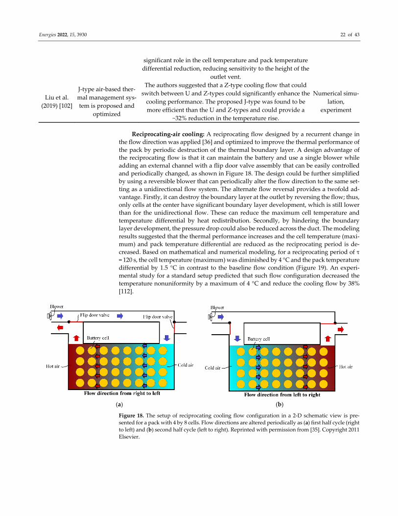
Reciprocating‐air cooling: A reciprocating flow designed by a recurrent change in
the flow direction was applied [36] and optimized to improve the thermal performance of
the pack by periodic destruction of the thermal boundary layer. A design advantage of
the reciprocating flow is that it can maintain the battery and use a single blower while
adding an external channel with a flip door valve assembly that can be easily controlled
and periodically changed, as shown in Figure 18. The design could be further simplified
by using a reversible blower that can periodically alter the flow direction to the same set‐
ting as a unidirectional flow system. The alternate flow reversal provides a twofold ad‐
vantage. Firstly, it can destroy the boundary layer at the outlet by reversing the flow; thus,
only cells at the center have significant boundary layer development, which is still lower
than for the unidirectional flow. These can reduce the maximum cell temperature and
temperature differential by heat redistribution. Secondly, by hindering the boundary
layer development, the pressure drop could also be reduced across the duct. The modeling
results suggested that the thermal performance increases and the cell temperature (maxi‐
mum) and pack temperature differential are reduced as the reciprocating period is de‐
creased. Based on mathematical and numerical modeling, for a reciprocating period of τ
= 120 s, the cell temperature (maximum) was diminished by 4 °C and the pack temperature
differential by 1.5 °C in contrast to the baseline flow condition (Figure 19). An experi‐
mental study for a standard setup predicted that such flow configuration decreased the
temperature nonuniformity by a maximum of 4 °C and reduce the cooling flow by 38%
[112].
(a) (b)
Figure 18. The setup of reciprocating cooling flow configuration in a 2‐D schematic view is pre‐
sented for a pack with 4 by 8 cells. Flow directions are altered periodically as (a) first half cycle (right
to left) and (b) second half cycle (left to right). Reprinted with permission from [35]. Copyright 2011
Elsevier.
Energies 2022, 15, 3930 23 of 43
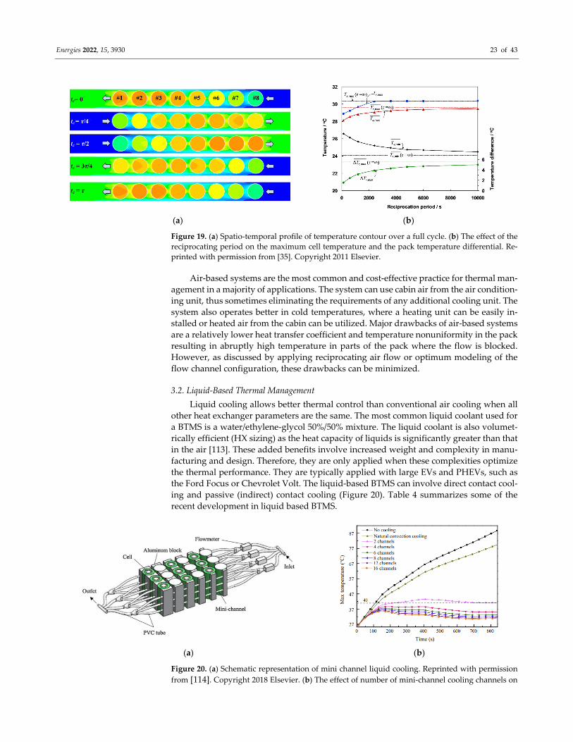
(a) (b)
Figure 19. (a) Spatio‐temporal profile of temperature contour over a full cycle. (b) The effect of the
reciprocating period on the maximum cell temperature and the pack temperature differential. Re‐
printed with permission from [35]. Copyright 2011 Elsevier.
Air‐based systems are the most common and cost‐effective practice for thermal man‐
agement in a majority of applications. The system can use cabin air from the air condition‐
ing unit, thus sometimes eliminating the requirements of any additional cooling unit. The
system also operates better in cold temperatures, where a heating unit can be easily in‐
stalled or heated air from the cabin can be utilized. Major drawbacks of air‐based systems
are a relatively lower heat transfer coefficient and temperature nonuniformity in the pack
resulting in abruptly high temperature in parts of the pack where the flow is blocked.
However, as discussed by applying reciprocating air flow or optimum modeling of the
flow channel configuration, these drawbacks can be minimized.
3.2. Liquid‐Based Thermal Management
Liquid cooling allows better thermal control than conventional air cooling when all
other heat exchanger parameters are the same. The most common liquid coolant used for
a BTMS is a water/ethylene‐glycol 50%/50% mixture. The liquid coolant is also volumet‐
rically efficient (HX sizing) as the heat capacity of liquids is significantly greater than that
in the air [113]. These added benefits involve increased weight and complexity in manu‐
facturing and design. Therefore, they are only applied when these complexities optimize
the thermal performance. They are typically applied with large EVs and PHEVs, such as
the Ford Focus or Chevrolet Volt. The liquid‐based BTMS can involve direct contact cool‐
ing and passive (indirect) contact cooling (Figure 20). Table 4 summarizes some of the
recent development in liquid based BTMS.
(a) (b)
Figure 20. (a) Schematic representation of mini channel liquid cooling. Reprinted with permission
from [114]. Copyright 2018 Elsevier. (b) The effect of number of mini‐channel cooling channels on

Energies 2022, 15, 3930 24 of 43
the maximum cell temperature (5C discharge). Reprinted with permission from [115]. Copyright 2015 Elsevier.
Direct liquid cooling: In direct liquid cooling, the heat transfer process is controlled
by conduction and convection by the surface of the battery. The heat transfer fluid should
have higher thermal conductivity, lower viscosity, and lower density; whereas it should
have lower corrosion properties and reaction capability with the battery material. The ma‐
jor fluids, such as water and oils (e.g., mineral, silicon,) can be employed for BTMS appli‐
cations. In addition, boiling liquids and nanofluids have also been involved in the battery
thermal management application as they can support a significant improvement in the
thermal transport and heat transfer coefficient. It is also a common practice to mix eth‐
ylene glycol with water during the winter season to prevent any freezing or so as men‐
tioned. Generally, oil‐based coolant provides a better heat transfer coefficient, while its
high viscosity significantly increases the pressure drop, consequently increasing the
pumping power.
Mineral oil‐based coolants have also been tested and found to be performed better
than the water‐based system at the cost of higher weight. A comprehensive computational
study of the different spacing and coolant types was studied by Park and Jung [91]. The
study suggested that air cooling provides better performance for a larger cell with smaller
inter cell‐spacing, whereas the liquid‐based system can perform better for a narrow cell
design. A comprehensive experiment of water‐based cooling showed that liquid‐based
BTMS was 3000 times more effective than the air‐based BTMS, whereas the parasitic loss
was reduced by 40% [116].
Boiling and nanofluid‐based coolant mechanisms have been promising as well. At a
10 C charging/discharging rate and using hydrofluoric ether as a heat transfer fluid, the
cell temperature was maintained at 35–50 °C, which was otherwise 80–90 °C for an air‐
cooling system. Using ammonia‐based coolant, Al‐Zareer et al. [117] showed that such
BTMS provides a better reduction in cell skin temperature, whereas the skin temperature
was < 40 °C and the charging and discharging rate was 7.5 C. The Al2O3‐based nanofluids
were used by Huo and Rao [118] as a cooling medium. Due to the high heat capacity of
nanofluids, the average cell temperature was found to be decreased by 7%. As compared
to nanofluids with flows, a condition on Al2O3‐based nanofluids with non‐circulation was
studied by Jilte et al. [119] and the results suggested that the system can perform well for
a moderate charge/discharge rate (2 C).
Indirect liquid cooling: The indirect‐based liquid cooling avoids any contact of the
cell surface to the coolant, thus reducing the possibility of corrosion and reaction, whereas
increasing the range of operating temperature for better performance provides better sup‐
port for the battery pack. In this case, the heat transfer fluids passed through a cold plate
attached or sandwiched to the sides of the cell. Though the passive cooling method can
implement better on prismatic cell configuration, the rounder contact supports the
transport of better heat from a cylindrical cell [115]. For a prismatic cell configuration, the
temperature increment for 4 C discharge rate, the air‐ and water‐based flows in a micro‐
channel can cause a temperature increment of 25 °C and 5 °C, respectively. The results
signify a significant decrease in average surface temperature based on indirect liquid cool‐
ing [113].
Liquid metals: The application of a liquid‐based BTMS could be further improved
by the application of liquid metal applications [120,121]. The liquid metal provides a much
higher thermal conductivity than the typical water or aqueous ethanol. Generally, alumi‐
num is a preferred choice because of its lightweight and high thermal conductivity. The
corrosion due to liquid metal application can be overcome by the anode coloring, which
isolates the liquid metal and Al. Another advantage of liquid cooling is electromagnetic
driving (EMO) where the change in flow direction can be attained (Figure 21). In addition,
these systems required limited maintenance costs and are much more reliable than the
liquid‐based system as they are applied in a rather simple and robust system. However,

Energies 2022, 15, 3930 25 of 43
as liquid metal has a significantly higher density (approximately six times water), this
type of BTMS adds significant weight for the same volume of coolant.
(a) (b)
Figure 21. (a) Working principle of an electromagnetic pump (EMP). (b) A comparison of module
average temperature between liquid metal cooling and water cooling. Reprinted with permission
from [120]. Copyright 2016 Elsevier.
Table 4. Recent developments in liquid‐based battery thermal management methods.
Authors Strategies Recommendations Methods
Yu et al.
(2005) [122]
Thermal manage‐
ment of PEM fuel
cell stack
An earlier model of water and thermal management system was
based upon mathematical analysis to attain the optimum result. Mathematical
Giuliano et al.
(2011) [23]
Aluminum cool‐
ing plates
At 300 A discharges, the proposed system was able to control the
temperature below 50 °C. Experiment
Jarrett and Kim
(2011, 2014)
[123,124]
Serpentine‐
channel shape
cooling plate
A serpentine channel shape cooling panel could optimize pressure
drop and maximum cell temperature; although, the temperature
differential increased. The temperature uniformity was found to be
most sensitive to the design operating conditions, especially the
heat flux and flow rate.
Numerical sim‐
ulation
Hung et al.
(2013) [125]
Nanofluids
(Al2O3/water)
For a nanofluidic‐based system, the most efficient performance was
obtained when nanofluid concentrations were ~0.5%, while the
flow rate was significantly lower (0.8 L/min).
Experiment
Bandhaeur et
al. (2013) [126]
Passive
microchannel
phase change
system (Liquid
R134a)
A new two‐phase refrigerant in the microchannel was tested for a
passive internal thermal management system. A correlation for the
friction factor for such a two‐phase system was proposed and
tested.
Experiment
Lan et al.
(2014) [127]
Mini‐channel
cooling
With a minimum expense of pumping power, the proposed system
can reduce both the cell temperature and the pack temperature
differential. At a discharge rate of 1 C, using a flow rate of 0.20
L/min, the maximum temperature rise was less than 27.81 °C,
whereas the temperature differential was 0.80 °C after 1 h of
discharging, with only 8.69 × 10⁻⁶ W pumping power required.
Numerical sim‐
ulation
Nieto et al.
(2014) [128] Cold plate
Maximum cell temperature and pack temperature differential were
lower than 35 °C and 5 °C, respectively.
Experiment,
numerical simu‐
lation
Panchal et al.
(2016) [113]
Mini‐channel wa‐
ter cooling
A mini‐channel water cooling system was tested for large prismatic
cells for the discharge of 1–2 C and operating temperatures of 5–
25 °C.
Experiment, nu‐
merical simula‐
tion
Energies 2022, 15, 3930 26 of 43
Huo et al.
(2014) [118]
Nanofluids
(Al2O3/water)
In a five cells pack, the Al2O3/water nanofluids decreased the maxi‐
mum cell temperature and also maintained the temperature uni‐
formity. For a 0.4 volume fraction of nanofluids, a maximum 7%
decrease in maximum cell temperature was obtained.
Numerical sim‐
ulation
Qian et al.
(2014) [129]
Geometries of in‐
let and outlet
flow ducts
The mini‐channel cold plate could attain the optimum operating
temperature when the discharge rate was as high as 5 C. The cell
temperature (maximum) and the pack temperature differential
decreased by 13.3% and 43.3%, respectively.
Analytical, nu‐
merical simula‐
tion
Zhang et al.
(2014) [130]
Water‐based
PAAS (sodium
polyacrylate) hy‐
drogel
The simulation and experimental results at a significantly high
discharge (10 A) demonstrate the excellent performance of the
hydrogel TMS in decreasing the temperature gain and minimizing
the temperature gradient inside the pack. A battery pack equipped
with the hydrogel TMS exhibits a reduced capacity fading.
Experiment, nu‐
merical simula‐
tion
Jin et al.
(2014) [131]
Oblique
minichannel
liquid cold plate
An oblique alignment of a mini‐channel liquid cold plate was
applied, where the performance was significantly higher than with
the normal liquid cold plate. The proposed structure could keep the
maximum surface temperature below the critical limit (50 °C) even
for a high thermal load (~1240 W) and a low flow rate (~0.9 L/min).
Experiment, nu‐
merical simula‐
tion
Tong et al.
(2015) [132]
Water and cool‐
ant plate
The thermal performance of the battery pack could be improved by
extending the coolant plate thickness and flow rate. The proposed
system could also increase the weight or volume; hence, an
optimum design condition is necessary.
Numerical sim‐
ulation
Huo et al.
(2015) [133]
Mini‐channel
cold plate
The maximum cell temperature decreased if the number of cooling
channels increased. The coolant performance could be improved
with a water flow lateral to the electrodes. The thermal
performance can be enhanced by increasing the flow rate; however,
the efficiency could decrease above the optimum operating
conditions.
Numerical sim‐
ulation
Saw et al.
(2015) [134] Liquid cooling
Thermal management systems were analyzed for liquid and air
cooling. It was suggested that among various methods available,
the direct contact liquid cooling system was more effective in
extracting the heat generated in the cell and creating an optimum
operating environment for the battery.
Numerical sim‐
ulation
Smith et al.
(2015) [135]
Three sample
cooling plate
concepts
It was shown that the ideal cooling plate design depends on the
anticipated cell heat loss and operating climate, as well as the
degree of structural integration within the vehicle.
Experiment
Chen et al.
(2016) [136]
Direct liquid, in‐
direct liquid, fin,
and air cooling
A 3‐dimensional electrochemical–thermal model was applied to
evaluate four BTMS (air, direct liquid cooling, indirect liquid
cooling, and fin‐type) and compared. Maintaining the same
average temperature for the air‐based method needed two to three
times higher energy. However, water/glycol was most efficient in
reducing the cell temperature compared to oil, air, or fins.
Numerical sim‐
ulation
Basu et al.
(2016) [137]
Aluminum sheets
wrapping/Liquid
coolant
The proposed system could reduce the maximum cell temperature
below 7 K even at high discharge. In addition, the system was
found to be efficient in cooling the pack at low flow rates.
Experiment, nu‐
merical simula‐
tion
Mondal et al.
(2017) [138]
Nanofluids
(ethylene glycol,
Al2O3, CuO)
Pure H2O‐based coolants offered better thermal performance in the
form of lower overall temperatures and less temperature gradient.
The enrichment with nanoparticles did not have a significant
impact on the pack temperature, despite the increase in thermal
conductivity.
Numerical sim‐
ulation

Energies 2022, 15, 3930 27 of 43
An et al.
(2017) [139]
Mini‐channel
(flow boiling)
The BTMS devised on hydrofluoroether flow boiling in micro‐
channels could keep temperatures of battery cells around 40 °C and
could improve the temperature uniformity in the cell.
Experiment
Gao et al.
(2022) [140]
Gradient channel
based
Optimally designed gradient channel design can enhance the
cooling performance of the BTMS. The proposed design can
significantly improve the thermal uniformity in the pack for a
lower inlet flow rate.
Experiment, nu‐
merical simula‐
tion
The water‐based BTMS offers a higher rate heat transfer coefficient and rapid con‐
vective heat transport. Compared to a conventional air‐cooling method, liquid cooling can
be compact and space‐conserving. At the same time, it can also support the temperature
uniformity in the entire pack or an individual cell. However, the system requires careful
consideration of the heat exchanger system, free from any water leakage that can cause a
safety incident. In addition, due to an extensive duct and pumping system along with
water storage, the system would be less cost‐effective than the air‐based BTMS.
3.3. PCM‐Based Thermal Management
PCM‐based materials exhibit excellent heat absorption properties utilizing the large
latent heat of fusion per unit volume capability that has previously been applied for resi‐
dential cooling applications, thermal management of electronics, spacecraft thermal man‐
agement, medical treatment, etc. In addition, a minimum change in volume during the
phase change and capability of intermittent or transient heat dissipative capability has
been proposed as an efficient method for battery thermal management. Common materi‐
als are paraffin, salt hydrates to the recent development of functionalized BioPCM and
organic materials. To reduce the thermal runaway conditions and high‐temperature gra‐
dient within the cell in a battery pack in an air‐based system, such a PCM‐based system
was experimentally and numerically tested for both winter and summer conditions by
Khateeb et al. [141] as shown in Figure 22. The setup was applied for a scooter with a 1 h
charging cycle. The results from the three cycles were shown in Figure 22b, where the cell
inside the pack (Cell‐3) exhibits the highest temperature. Recent developments of the
phase change BTMS are summarized in Table 5.
(a) (b)
Figure 22. (a) Li‐ion battery cell filled with PCM. (b) Temperature rise of Li‐ion cells and three dif‐
ferent PCMS settings. Reprinted with permission from [142]. Copyright 2004 Elsevier

Energies 2022, 15, 3930 28 of 43
Table 5. Recent developments of PCM‐based battery thermal management methods.
Authors Materials Recommendations Methods
Hallaj et al.
(2000) [143] Paraffin
A PCM‐based BTMS was studied for 18650 cells. Excess heat emitted
during discharge could be transferred and stored in the surrounding
PCMs, which could heat the cell during charging. As the PCM has a
lower melting point, these reverse thermal transport processes were
activated when the cell temperature fell below the PCM melting
temperature. The PCM‐based method is promising in cold climates
and space conditions.
Experiment, nu‐
merical simula‐
tion
Khateeb et al.
(2004) [141]
Composite
(Paraffin and Al foam)
The Al foam with PCM could reduce the cell temperature by a maxi‐
mum of 50% in contrast to the application of any BTMS. PCM meth‐
ods were used to maintain uniformity in the pack. However, the poor
heat conductivity of PCM could decrease the performance of the
BTMS.
Experiment, nu‐
merical simula‐
tion
Qu et al.
(2014) [144] Paraffin and foam
A PCM‐based method was tested for paraffin in copper foam by a de‐
tailed thermo‐electrochemical model. The proposed copper‐embed‐
ded paraffin foam could significantly reduce the cell temperature
within the operating temperature range for a discharge of 3 C, which
was not possible by a conventional air‐based system.
Numerical sim‐
ulation
Lin et al.
(2014) [145] Foam Paraffin composite
The proposed foam paraffin composite saturated with PCM materials
could achieve a significantly higher thermal performance than the
pure PCM‐based system. It was also suggested that the growth of po‐
rosity and density of pore could increase the cell surface temperature.
Experiment
Javani et al.
(2014) [146] Polyurethane foam
PCM saturated Polyurethane foam could increase the performance
significantly as compared to the dry foam. For example, the use of
PCM soaked foam decreased the surface temperature by 7.3 K more
than that of dry foam. This method could also enhance the temperate
homogeneity in the battery pack.
Numerical sim‐
ulation
Hemery et al.
(2014) [147] PCM with air cooling
The wall temperature of a defective cell remains under 60 °C during
the failure test. The PCM‐can/cell weight ratio is about 46.7%, com‐
pared to 28.6% obtained by Khateeb et al. [141].
Experiment
Ling et al.
(2015) [148]
PCM with forced air
cooling
The combined method can remarkably enhance thermal performance
and reduce heat accumulation. The proposed system could also
maintain the cell temperature under all cycle conditions (1.5 C and 2
C discharge rates).
Numerical sim‐
ulation
Wang et al.
(2015) [149]
Paraffin and paraffin/alu‐
minum foam
The aluminum foam was used along with paraffin in an attempt to
decrease the melting temperature and enhance the temperature uni‐
formity in the PCM system. For the heat flux of 7000 W/m2 and 12,000
W/m2, the energy storage time of the proposed structure was 73.6%
and 74.4%, respectively, for the pure paraffin.
Numerical sim‐
ulation
Babapoor et al.
(2015) [150]
Composite
(Carbon fiber)
Composite PCM (with carbon fibers) was proposed. It was suggested
that a composition of 2 mm long carbon fibers and 0.46% (mass
fraction) carbon fibers could provide the optimal performance, and
the maximum temperature could be reduced by a maximum of 45%.
Numerical sim‐
ulation
Shirazi et al.
(2015) [151]
Composite
(paraffin, graphene, car‐
bon fiber, fullerene)
It was reported that the application of paraffin nanocomposites could
be beneficial when the battery undergoes fast and nonstop discharg‐
ing cycles.
Numerical sim‐
ulation
Rao et al.
(2016) [152]
Composite
(PCM/mini‐channel cou‐
pled)
A PCM and mini‐channel coupled system was proposed. For eight
mini‐channels and an 8 × 10⁻⁴ kg s−1 flow rate, the optimal operating
temperature and thermal conductivity for the PCM were 308.15 K and
0.6 W m−1 K−1, respectively. In addition, for the same operating condi‐
tions, when the maximum temperature of the PCM‐based BTMS was
335.4 K, the maximum temperature for the proposed system was
320.6 K.
Numerical sim‐
ulation
Yang et al.
(2016) [153]
Phase change microcap‐
sule
The proposed phase changed microcapsule (n‐octadecane enriched
polymethylmethacrylate shell) could improve the thermal property Experiment

Energies 2022, 15, 3930 29 of 43
significantly. The addition of silicon nitride could enhance the ther‐
mal conductivity by 56.8%.
Sun et al.
(2016) [154] Fin structures in PCM
Fin structures (with an optimum number of 1 and 8) could maintain
the cell temperature within the operating range even for a heat gener‐
ation of 20 W.
Numerical sim‐
ulation
Hussain et al.
(2016) [155]
Nickel foam–paraffin
composite
Nickel foam fused paraffin composite could significantly enhance
thermal performance. Under 2 C discharge rate, the proposed struc‐
ture reduces the cell temperature by 31% and 24% when compared
with natural convection and pure PCM.
Experiment
Alipanah et al.
(2016) [156]
Pure gallium and octade‐
cane–Al foam composite
A set of PCMS with Al foam composite was tested. Gallium as PCM
could enhance the surface temperature uniformity and discharge
time. Whereas, AL foam with Octadecane could achieve a significant
uniformity in surface temperature.
Numerical sim‐
ulation
Karimi et al.
(2016) [157]
Metal matrix and nano‐
particles with PCM
A metal matrix–PCM composite was recommended as a better substi‐
tute than the nanoparticle PCM composite. In addition, among differ‐
ent nanoparticles, composite containing Ag nanoparticles predicted
the best thermal performance.
Experiment
Samimi et al.
(2016) [158]
Composite
(Carbon fiber)
Carbon fiber‐based composite was suggested to enhance the tempera‐
ture uniformity in the pack. In addition, carbon fiber‐based composite
could enhance the thermal conductivity by an average of 105%.
Numerical sim‐
ulation
Malik et al.
(2016) [159]
Composite
(Graphite)
Graphite‐based composite is proposed to be effective and could in‐
crease the thermal conductivity by up to 70 W m−1K−1.
Numerical sim‐
ulation
Jiang et al.
(2016) [160]
Paraffin (RT44HC)/ex‐
panded graphite (EG)
composite
EG incorporation dramatically enhanced the thermal conductivity of
the composite. Hence, the cell temperature could be remarkably de‐
creased, whereas the optimum mixture was proposed as a composite
with 16–20 wt.% EG.
Numerical sim‐
ulation
Lv et al.
(2016) [161]
Paraffin (PA) and low‐
density polyethylene
(LDPE)
The PCM composite kept the maximum cell temperature below 50 °C
and reduced the temperature differential by 5 °C for a battery pack
working under the safety temperature of 50 °C and up to a very high
discharge rate (3.5 C).
Experiment
Wu et al.
(2016) [162]
Composite
(Paraffin with copper
mesh)
Copper mesh embedded PCM could significantly enhance the tem‐
perature uniformity than the pure PCM. These methods were recom‐
mended to be more effective in harsh working conditions.
Experiment
Azizi et al.
(2016) [163]
Composite
(Poly Ethylene Glycol
with aluminum wire
mesh)
The PCM and use of aluminum wire mesh in the cell spacing reduced
the cell skin temperatures at ambient conditions by a maximum of
26% at a discharge rate of 3 C.
Numerical sim‐
ulation
Ling et al.
(2014) [148]
EG (Ethylene Glycol)
based PCM
It was suggested that PCMs with too low or high melting
temperatures deteriorate the performance, and a melting temperature
of 40–45 °C could give the best thermal performance. As expected, the
discharge time and rates decrease the temperature uniformity.
Conversely, the proposed method could maintain the maximum
temperature differential at 5 °C at a discharge rate of 2 C.
Experiment, nu‐
merical simula‐
tion
Wu et al.
(2017) [164]
Heat pipe‐assisted phase
change material
The proposed technique was recommended with liquid cooling,
which could keep the maximum cell temperature beneath 50 °C for a
discharge rate of 3 C.
Experiment
Hao et al.
(2018) [165]
Shape memory alloy‐
based passive interfacial
thermal regulator
A shape memory‐based thermal regulator was proposed that could
adjust its thermal conductivity depending on the temperature. This
regulator was found to increase the battery capacity by three times at
−20 °C compared to a conventional BTMS with no thermal regulation
function. This method was recommended for extreme environmental
conditions.
Experiment
The PCM‐based system provides as many benefits as a water‐based system in terms
of heat transfer coefficient while removing a few of the major drawbacks of the water‐
based system, such as requirements for extensive water circulation pipes, pumping and
storage unit, and insulation for any possible leakage. The PCM system also provides good
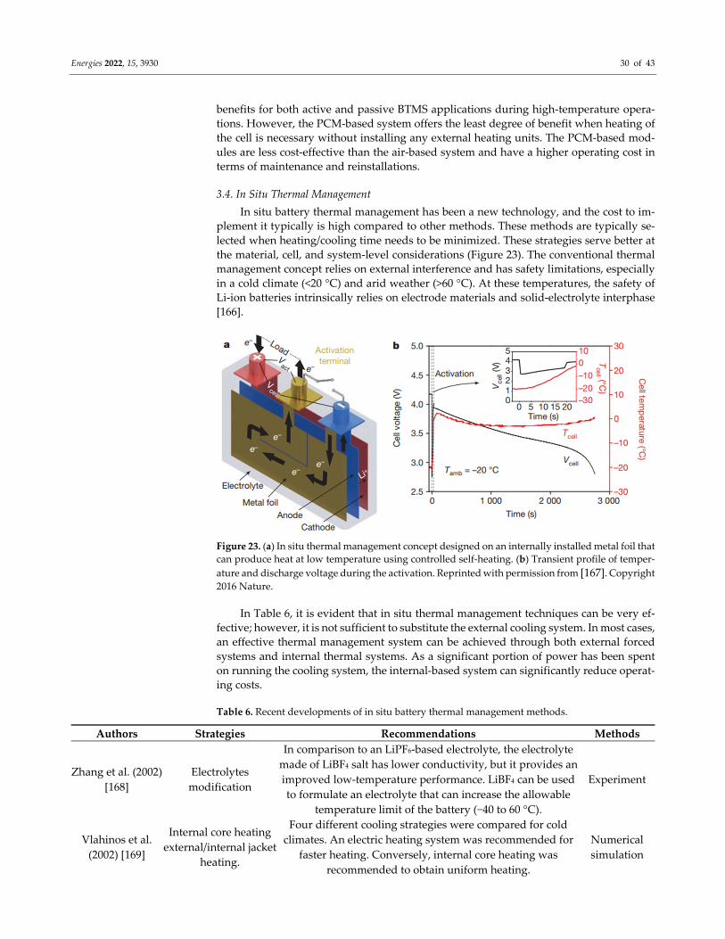
Energies 2022, 15, 3930 30 of 43
benefits for both active and passive BTMS applications during high‐temperature opera‐
tions. However, the PCM‐based system offers the least degree of benefit when heating of
the cell is necessary without installing any external heating units. The PCM‐based mod‐
ules are less cost‐effective than the air‐based system and have a higher operating cost in
terms of maintenance and reinstallations.
3.4. In Situ Thermal Management In situ battery thermal management has been a new technology, and the cost to im‐
plement it typically is high compared to other methods. These methods are typically se‐
lected when heating/cooling time needs to be minimized. These strategies serve better at
the material, cell, and system‐level considerations (Figure 23). The conventional thermal
management concept relies on external interference and has safety limitations, especially
in a cold climate (<20 °C) and arid weather (>60 °C). At these temperatures, the safety of
Li‐ion batteries intrinsically relies on electrode materials and solid‐electrolyte interphase
[166].
Figure 23. (a) In situ thermal management concept designed on an internally installed metal foil that
can produce heat at low temperature using controlled self‐heating. (b) Transient profile of temper‐
ature and discharge voltage during the activation. Reprinted with permission from [167]. Copyright 2016 Nature.
In Table 6, it is evident that in situ thermal management techniques can be very ef‐
fective; however, it is not sufficient to substitute the external cooling system. In most cases,
an effective thermal management system can be achieved through both external forced
systems and internal thermal systems. As a significant portion of power has been spent
on running the cooling system, the internal‐based system can significantly reduce operat‐
ing costs.
Table 6. Recent developments of in situ battery thermal management methods.
Authors Strategies Recommendations Methods
Zhang et al. (2002)
[168]
Electrolytes
modification
In comparison to an LiPF6‐based electrolyte, the electrolyte
made of LiBF4 salt has lower conductivity, but it provides an
improved low‐temperature performance. LiBF4 can be used
to formulate an electrolyte that can increase the allowable
temperature limit of the battery (−40 to 60 °C).
Experiment
Vlahinos et al.
(2002) [169]
Internal core heating
external/internal jacket
heating.
Four different cooling strategies were compared for cold
climates. An electric heating system was recommended for
faster heating. Conversely, internal core heating was
recommended to obtain uniform heating.
Numerical
simulation
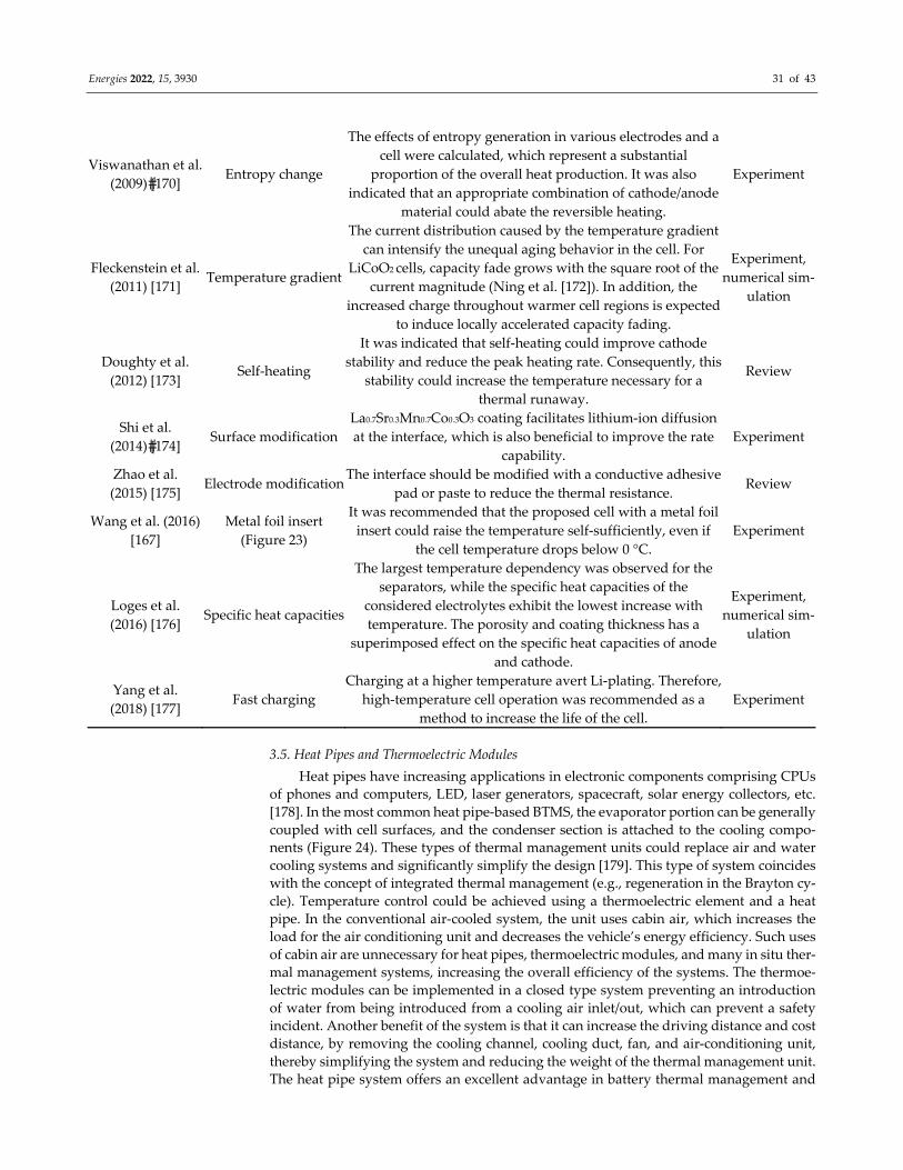
Energies 2022, 15, 3930 31 of 43
Viswanathan et al.
(2009) [170] Entropy change
The effects of entropy generation in various electrodes and a
cell were calculated, which represent a substantial
proportion of the overall heat production. It was also
indicated that an appropriate combination of cathode/anode
material could abate the reversible heating.
Experiment
Fleckenstein et al.
(2011) [171] Temperature gradient
The current distribution caused by the temperature gradient
can intensify the unequal aging behavior in the cell. For
LiCoO2 cells, capacity fade grows with the square root of the
current magnitude (Ning et al. [172]). In addition, the
increased charge throughout warmer cell regions is expected
to induce locally accelerated capacity fading.
Experiment,
numerical sim‐
ulation
Doughty et al.
(2012) [173] Self‐heating
It was indicated that self‐heating could improve cathode
stability and reduce the peak heating rate. Consequently, this
stability could increase the temperature necessary for a
thermal runaway.
Review
Shi et al.
(2014) [174] Surface modification
La0.7Sr0.3Mn0.7Co0.3O3 coating facilitates lithium‐ion diffusion
at the interface, which is also beneficial to improve the rate
capability.
Experiment
Zhao et al.
(2015) [175] Electrode modification
The interface should be modified with a conductive adhesive
pad or paste to reduce the thermal resistance. Review
Wang et al. (2016)
[167]
Metal foil insert
(Figure 23)
It was recommended that the proposed cell with a metal foil
insert could raise the temperature self‐sufficiently, even if
the cell temperature drops below 0 °C.
Experiment
Loges et al.
(2016) [176] Specific heat capacities
The largest temperature dependency was observed for the
separators, while the specific heat capacities of the
considered electrolytes exhibit the lowest increase with
temperature. The porosity and coating thickness has a
superimposed effect on the specific heat capacities of anode
and cathode.
Experiment,
numerical sim‐
ulation
Yang et al.
(2018) [177] Fast charging
Charging at a higher temperature avert Li‐plating. Therefore,
high‐temperature cell operation was recommended as a
method to increase the life of the cell.
Experiment
3.5. Heat Pipes and Thermoelectric Modules
Heat pipes have increasing applications in electronic components comprising CPUs
of phones and computers, LED, laser generators, spacecraft, solar energy collectors, etc.
[178]. In the most common heat pipe‐based BTMS, the evaporator portion can be generally
coupled with cell surfaces, and the condenser section is attached to the cooling compo‐
nents (Figure 24). These types of thermal management units could replace air and water
cooling systems and significantly simplify the design [179]. This type of system coincides
with the concept of integrated thermal management (e.g., regeneration in the Brayton cy‐
cle). Temperature control could be achieved using a thermoelectric element and a heat
pipe. In the conventional air‐cooled system, the unit uses cabin air, which increases the
load for the air conditioning unit and decreases the vehicle’s energy efficiency. Such uses
of cabin air are unnecessary for heat pipes, thermoelectric modules, and many in situ ther‐
mal management systems, increasing the overall efficiency of the systems. The thermoe‐
lectric modules can be implemented in a closed type system preventing an introduction
of water from being introduced from a cooling air inlet/out, which can prevent a safety
incident. Another benefit of the system is that it can increase the driving distance and cost
distance, by removing the cooling channel, cooling duct, fan, and air‐conditioning unit,
thereby simplifying the system and reducing the weight of the thermal management unit.
The heat pipe system offers an excellent advantage in battery thermal management and
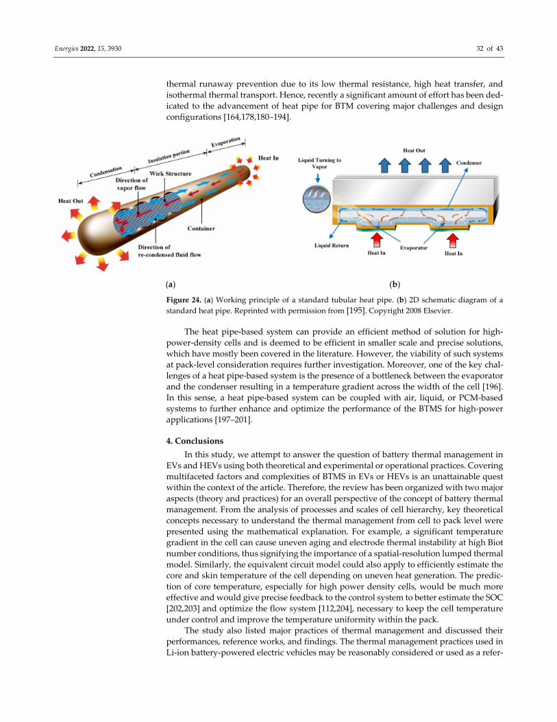
Energies 2022, 15, 3930 32 of 43
thermal runaway prevention due to its low thermal resistance, high heat transfer, and
isothermal thermal transport. Hence, recently a significant amount of effort has been ded‐
icated to the advancement of heat pipe for BTM covering major challenges and design
configurations [164,178,180–194].
(a) (b)
Figure 24. (a) Working principle of a standard tubular heat pipe. (b) 2D schematic diagram of a
standard heat pipe. Reprinted with permission from [195]. Copyright 2008 Elsevier.
The heat pipe‐based system can provide an efficient method of solution for high‐
power‐density cells and is deemed to be efficient in smaller scale and precise solutions,
which have mostly been covered in the literature. However, the viability of such systems
at pack‐level consideration requires further investigation. Moreover, one of the key chal‐
lenges of a heat pipe‐based system is the presence of a bottleneck between the evaporator
and the condenser resulting in a temperature gradient across the width of the cell [196].
In this sense, a heat pipe‐based system can be coupled with air, liquid, or PCM‐based
systems to further enhance and optimize the performance of the BTMS for high‐power
applications [197–201].
4. Conclusions
In this study, we attempt to answer the question of battery thermal management in
EVs and HEVs using both theoretical and experimental or operational practices. Covering
multifaceted factors and complexities of BTMS in EVs or HEVs is an unattainable quest
within the context of the article. Therefore, the review has been organized with two major
aspects (theory and practices) for an overall perspective of the concept of battery thermal
management. From the analysis of processes and scales of cell hierarchy, key theoretical
concepts necessary to understand the thermal management from cell to pack level were
presented using the mathematical explanation. For example, a significant temperature
gradient in the cell can cause uneven aging and electrode thermal instability at high Biot
number conditions, thus signifying the importance of a spatial‐resolution lumped thermal
model. Similarly, the equivalent circuit model could also apply to efficiently estimate the
core and skin temperature of the cell depending on uneven heat generation. The predic‐
tion of core temperature, especially for high power density cells, would be much more
effective and would give precise feedback to the control system to better estimate the SOC
[202,203] and optimize the flow system [112,204], necessary to keep the cell temperature
under control and improve the temperature uniformity within the pack.
The study also listed major practices of thermal management and discussed their
performances, reference works, and findings. The thermal management practices used in
Li‐ion battery‐powered electric vehicles may be reasonably considered or used as a refer‐
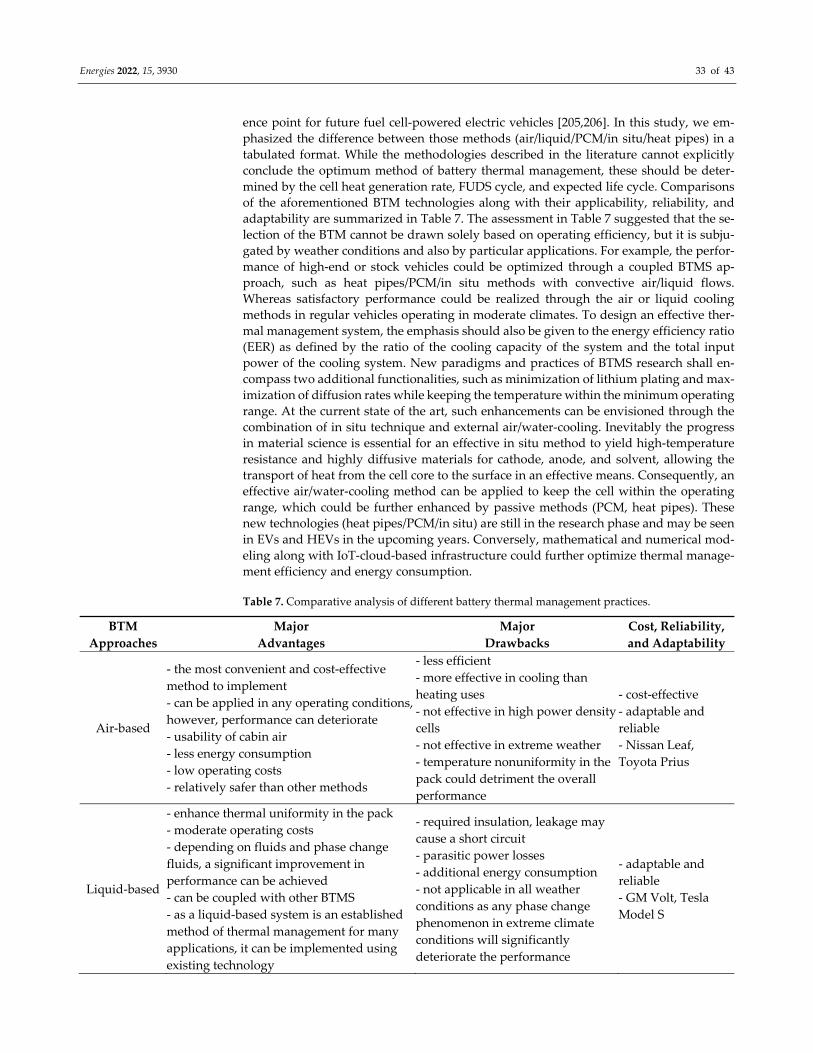
Energies 2022, 15, 3930 33 of 43
ence point for future fuel cell‐powered electric vehicles [205,206]. In this study, we em‐
phasized the difference between those methods (air/liquid/PCM/in situ/heat pipes) in a
tabulated format. While the methodologies described in the literature cannot explicitly
conclude the optimum method of battery thermal management, these should be deter‐
mined by the cell heat generation rate, FUDS cycle, and expected life cycle. Comparisons
of the aforementioned BTM technologies along with their applicability, reliability, and
adaptability are summarized in Table 7. The assessment in Table 7 suggested that the se‐
lection of the BTM cannot be drawn solely based on operating efficiency, but it is subju‐
gated by weather conditions and also by particular applications. For example, the perfor‐
mance of high‐end or stock vehicles could be optimized through a coupled BTMS ap‐
proach, such as heat pipes/PCM/in situ methods with convective air/liquid flows.
Whereas satisfactory performance could be realized through the air or liquid cooling
methods in regular vehicles operating in moderate climates. To design an effective ther‐
mal management system, the emphasis should also be given to the energy efficiency ratio
(EER) as defined by the ratio of the cooling capacity of the system and the total input
power of the cooling system. New paradigms and practices of BTMS research shall en‐
compass two additional functionalities, such as minimization of lithium plating and max‐
imization of diffusion rates while keeping the temperature within the minimum operating
range. At the current state of the art, such enhancements can be envisioned through the
combination of in situ technique and external air/water‐cooling. Inevitably the progress
in material science is essential for an effective in situ method to yield high‐temperature
resistance and highly diffusive materials for cathode, anode, and solvent, allowing the
transport of heat from the cell core to the surface in an effective means. Consequently, an
effective air/water‐cooling method can be applied to keep the cell within the operating
range, which could be further enhanced by passive methods (PCM, heat pipes). These
new technologies (heat pipes/PCM/in situ) are still in the research phase and may be seen
in EVs and HEVs in the upcoming years. Conversely, mathematical and numerical mod‐
eling along with IoT‐cloud‐based infrastructure could further optimize thermal manage‐
ment efficiency and energy consumption.
Table 7. Comparative analysis of different battery thermal management practices.
BTM
Approaches
Major
Advantages
Major
Drawbacks
Cost, Reliability,
and Adaptability
Air‐based
‐ the most convenient and cost‐effective
method to implement
‐ can be applied in any operating conditions,
however, performance can deteriorate
‐ usability of cabin air
‐ less energy consumption
‐ low operating costs
‐ relatively safer than other methods
‐ less efficient
‐ more effective in cooling than
heating uses
‐ not effective in high power density
cells
‐ not effective in extreme weather
‐ temperature nonuniformity in the
pack could detriment the overall
performance
‐ cost‐effective
‐ adaptable and
reliable
‐ Nissan Leaf,
Toyota Prius
Liquid‐based
‐ enhance thermal uniformity in the pack
‐ moderate operating costs
‐ depending on fluids and phase change
fluids, a significant improvement in
performance can be achieved
‐ can be coupled with other BTMS
‐ as a liquid‐based system is an established
method of thermal management for many
applications, it can be implemented using
existing technology
‐ required insulation, leakage may
cause a short circuit
‐ parasitic power losses
‐ additional energy consumption
‐ not applicable in all weather
conditions as any phase change
phenomenon in extreme climate
conditions will significantly
deteriorate the performance
‐ adaptable and
reliable
‐ GM Volt, Tesla
Model S
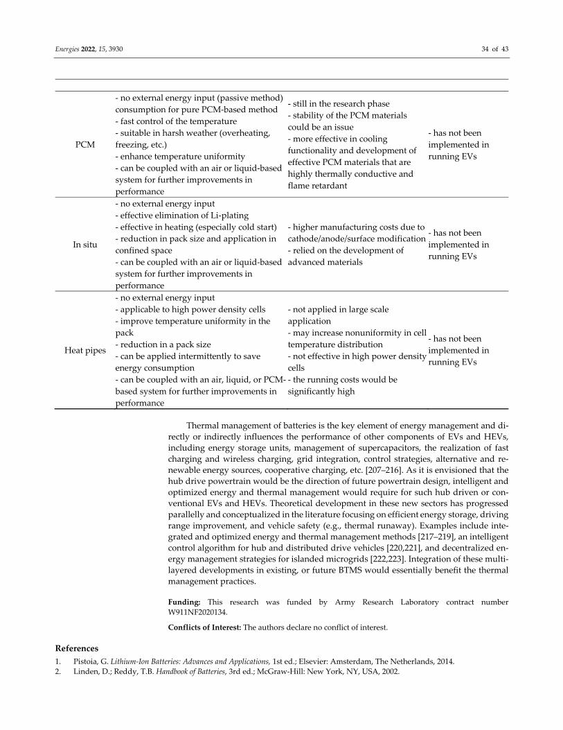
Energies 2022, 15, 3930 34 of 43
PCM
‐ no external energy input (passive method)
consumption for pure PCM‐based method
‐ fast control of the temperature
‐ suitable in harsh weather (overheating,
freezing, etc.)
‐ enhance temperature uniformity
‐ can be coupled with an air or liquid‐based
system for further improvements in
performance
‐ still in the research phase
‐ stability of the PCM materials
could be an issue
‐ more effective in cooling
functionality and development of
effective PCM materials that are
highly thermally conductive and
flame retardant
‐ has not been
implemented in
running EVs
In situ
‐ no external energy input
‐ effective elimination of Li‐plating
‐ effective in heating (especially cold start)
‐ reduction in pack size and application in
confined space
‐ can be coupled with an air or liquid‐based
system for further improvements in
performance
‐ higher manufacturing costs due to
cathode/anode/surface modification
‐ relied on the development of
advanced materials
‐ has not been
implemented in
running EVs
Heat pipes
‐ no external energy input
‐ applicable to high power density cells
‐ improve temperature uniformity in the
pack
‐ reduction in a pack size
‐ can be applied intermittently to save
energy consumption
‐ can be coupled with an air, liquid, or PCM‐
based system for further improvements in
performance
‐ not applied in large scale
application
‐ may increase nonuniformity in cell
temperature distribution
‐ not effective in high power density
cells
‐ the running costs would be
significantly high
‐ has not been
implemented in
running EVs
Thermal management of batteries is the key element of energy management and di‐
rectly or indirectly influences the performance of other components of EVs and HEVs,
including energy storage units, management of supercapacitors, the realization of fast
charging and wireless charging, grid integration, control strategies, alternative and re‐
newable energy sources, cooperative charging, etc. [207–216]. As it is envisioned that the
hub drive powertrain would be the direction of future powertrain design, intelligent and
optimized energy and thermal management would require for such hub driven or con‐
ventional EVs and HEVs. Theoretical development in these new sectors has progressed
parallelly and conceptualized in the literature focusing on efficient energy storage, driving
range improvement, and vehicle safety (e.g., thermal runaway). Examples include inte‐
grated and optimized energy and thermal management methods [217–219], an intelligent
control algorithm for hub and distributed drive vehicles [220,221], and decentralized en‐
ergy management strategies for islanded microgrids [222,223]. Integration of these multi‐
layered developments in existing, or future BTMS would essentially benefit the thermal
management practices.
Funding: This research was funded by Army Research Laboratory contract number
W911NF2020134.
Conflicts of Interest: The authors declare no conflict of interest.
References
1. Pistoia, G. Lithium‐Ion Batteries: Advances and Applications, 1st ed.; Elsevier: Amsterdam, The Netherlands, 2014.
2. Linden, D.; Reddy, T.B. Handbook of Batteries, 3rd ed.; McGraw‐Hill: New York, NY, USA, 2002.
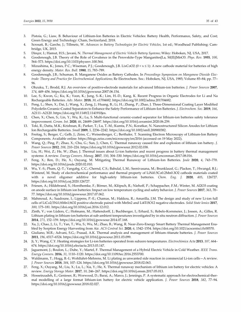
Energies 2022, 15, 3930 35 of 43
3. Pistoia, G.; Liaw, B. Behaviour of Lithium‐Ion Batteries in Electric Vehicles: Battery Health, Performance, Safety, and Cost;
Green Energy and Technology: Cham, Switzerland, 2018.
4. Scrosati, B.; Garche, J.; Tillmetz, W. Advances in Battery Technologies for Electric Vehicles, 1st ed.; Woodhead Publishing: Cam‐
bridge, UK, 2015.
5. Dinçer, I.; Hamut, H.S.; Javani, N. Thermal Management of Electric Vehicle Battery Systems; Wiley: Hoboken, NJ, USA, 2017.
6. Goodenough, J.B. Theory of the Role of Covalence in the Perovskite‐Type Manganites[La, M(II)]MnO3. Phys. Rev. 1955, 100,
564–573. https://doi.org/10.1103/physrev.100.564.
7. Mizushima, K.; Jones, P.C.; Wiseman, P.J.; Goodenough, J.B. LixCoO2 (0 < x ≤ 1): A new cathode material for batteries of high
energy density. Mater. Res. Bull. 1980, 15, 783–789.
8. Goodenough, J.B.; Schuman, B. Manganese Oxides as Battery Cathodes. In Proceedings Symposium on Manganese Dioxide Elec‐
trode: Theory and Practice for Electrochemical Applications; Re Electrochem. Soc.: Hoboken, NJ, USA, 1985; Volume 85–84; pp. 77–
96.
9. Ohzuku, T.; Brodd, R.J. An overview of positive‐electrode materials for advanced lithium‐ion batteries. J. Power Sources 2007,
174, 449–456. https://doi.org/10.1016/j.jpowsour.2007.06.154.
10. Lee, S.; Kwon, G.; Ku, K.; Yoon, K.; Jung, S.‐K.; Lim, H.‐D.; Kang, K. Recent Progress in Organic Electrodes for Li and Na
Rechargeable Batteries. Adv. Mater. 2018, 30, e1704682. https://doi.org/10.1002/adma.201704682.
11. Peng, L.; Shen, X.; Dai, J.; Wang, X.; Zeng, J.; Huang, B.; Li, H.; Zhang, P.; Zhao, J. Three‐Dimensional Coating Layer Modified
Polyolefin Ceramic‐Coated Separators to Enhance the Safety Performance of Lithium‐Ion Batteries. J. Electrochem. Soc. 2019, 166,
A2111–A2120. https://doi.org/10.1149/2.1141910jes.
12. Chen, X.; Chen, S.; Lin, Y.; Wu, K.; Lu, S. Multi‐functional ceramic‐coated separator for lithium‐ion batteries safety tolerance
improvement. Ceram. Int. 2020, 46, 24689–24697. https://doi.org/10.1016/j.ceramint.2020.06.259.
13. Teki, R.; Datta, M.K.; Krishnan, R.; Parker, T.; Lu, T.‐M.; Kumta, P.N.; Koratkar, N. Nanostructured Silicon Anodes for Lithium
Ion Rechargeable Batteries. Small 2009, 5, 2236–2242. https://doi.org/10.1002/smll.200900382.
14. Freitag, S.; Berger, C.; Gelb, J.; Zeiss, C.; Weisenberger, C.; Berthaler, T. Scanning Electron Microscopy of Lithium‐Ion Battery
Components. Available online: https://blogs.zeiss.com/microscopy/en/2016 (accessed on 19 May 2022).
15. Wang, Q.; Ping, P.; Zhao, X.; Chu, G.; Sun, J.; Chen, C. Thermal runaway caused fire and explosion of lithium ion battery. J.
Power Sources 2012, 208, 210–224. https://doi.org/10.1016/j.jpowsour.2012.02.038.
16. Liu, H.; Wei, Z.; He, W.; Zhao, J. Thermal issues about Li‐ion batteries and recent progress in battery thermal management
systems: A review. Energy Convers. Manag. 2017, 150, 304–330. https://doi.org/10.1016/j.enconman.2017.08.016.
17. Feng, X.; Ren, D.; He, X.; Ouyang, M. Mitigating Thermal Runaway of Lithium‐Ion Batteries. Joule 2020, 4, 743–770.
https://doi.org/10.1016/j.joule.2020.02.010.
18. Wu, Y.‐S.; Pham, Q.‐T.; Yangabg, C.C.; Chernd, C.S.; Babulal, L.M.; Seenivasana, M.; Brunklausf, G.; Plackee, T.; Hwangd, B.J.;
Winteref, M. Study of electrochemical performance and thermal property of LiNi0.5Co0.2Mn0.3O2 cathode materials coated
with a novel oligomer additive for high‐safety lithium‐ion batteries. Chem. Eng. J. 2020, 405, 126727.
https://doi.org/10.1016/j.cej.2020.126727.
19. Friesen, A.; Hildebrand, S.; Horsthemke, F.; Börner, M.; Klöpsch, R.; Niehoff, P.; Schappacher, F.M.; Winter, M. Al2O3 coating
on anode surface in lithium ion batteries: Impact on low temperature cycling and safety behavior. J. Power Sources 2017, 363, 70–
77. https://doi.org/10.1016/j.jpowsour.2017.07.062.
20. Mahmoud, A.; Saadoune, I.; Lippens, P.‐E.; Chamas, M.; Hakkou, R.; Amarilla, J.M. The design and study of new Li‐ion full
cells of LiCo2/3Ni1/6Mn1/6O2 positive electrode paired with MnSn2 and Li4Ti5O12 negative electrodes. Solid State Ionics 2017,
300, 175–181. https://doi.org/10.1016/j.ssi.2016.12.012.
21. Zinth, V.; von Lüders, C.; Hofmann, M.; Hattendorff, J.; Buchberger, I.; Erhard, S.; Rebelo‐Kornmeier, J.; Jossen, A.; Gilles, R.
Lithium plating in lithium‐ion batteries at sub‐ambient temperatures investigated by in situ neutron diffraction. J. Power Sources
2014, 271, 152–159. https://doi.org/10.1016/j.jpowsour.2014.07.168.
22. Xu, J.; Chao, J.; Li, T.; Yan, T.; Wu, S.; Wu, M.; Zhao, B.; Wang, R. Near‐Zero‐Energy Smart Battery Thermal Management Ena‐
bled by Sorption Energy Harvesting from Air. ACS Central Sci. 2020, 6, 1542–1554. https://doi.org/10.1021/acscentsci.0c00570.
23. Giuliano, M.R.; Advani, S.G.; Prasad, A.K. Thermal analysis and management of lithium–titanate batteries. J. Power Sources
2011, 196, 6517–6524. https://doi.org/10.1016/j.jpowsour.2011.03.099.
24. Ji, Y.; Wang, C.Y. Heating strategies for Li‐ion batteries operated from subzero temperatures. Electrochimica Acta 2013, 107, 664–
674. https://doi.org/10.1016/j.electacta.2013.03.147.
25. Jaguemont, J.; Boulon, L.; Dube, Y.; Martel, F. Thermal Management of a Hybrid Electric Vehicle in Cold Weather. IEEE Trans.
Energy Convers. 2016, 31, 1110–1120. https://doi.org/10.1109/tec.2016.2553700.
26. Waldmann, T.; Hogg, B.‐I.; Wohlfahrt‐Mehrens, M. Li plating as unwanted side reaction in commercial Li‐ion cells—A review.
J. Power Sources 2018, 384, 107–124. https://doi.org/10.1016/j.jpowsour.2018.02.063.
27. Feng, X.; Ouyang, M.; Liu, X.; Lu, L.; Xia, Y.; He, X. Thermal runaway mechanism of lithium ion battery for electric vehicles: A
review. Energy Storage Mater. 2017, 10, 246–267. https://doi.org/10.1016/j.ensm.2017.05.013.
28. Hosseinzadeh, E.; Genieser, R.; Worwood, D.; Barai, A.; Marco, J.; Jennings, P. A systematic approach for electrochemical‐ther‐
mal modelling of a large format lithium‐ion battery for electric vehicle application. J. Power Sources 2018, 382, 77–94.
https://doi.org/10.1016/j.jpowsour.2018.02.027.
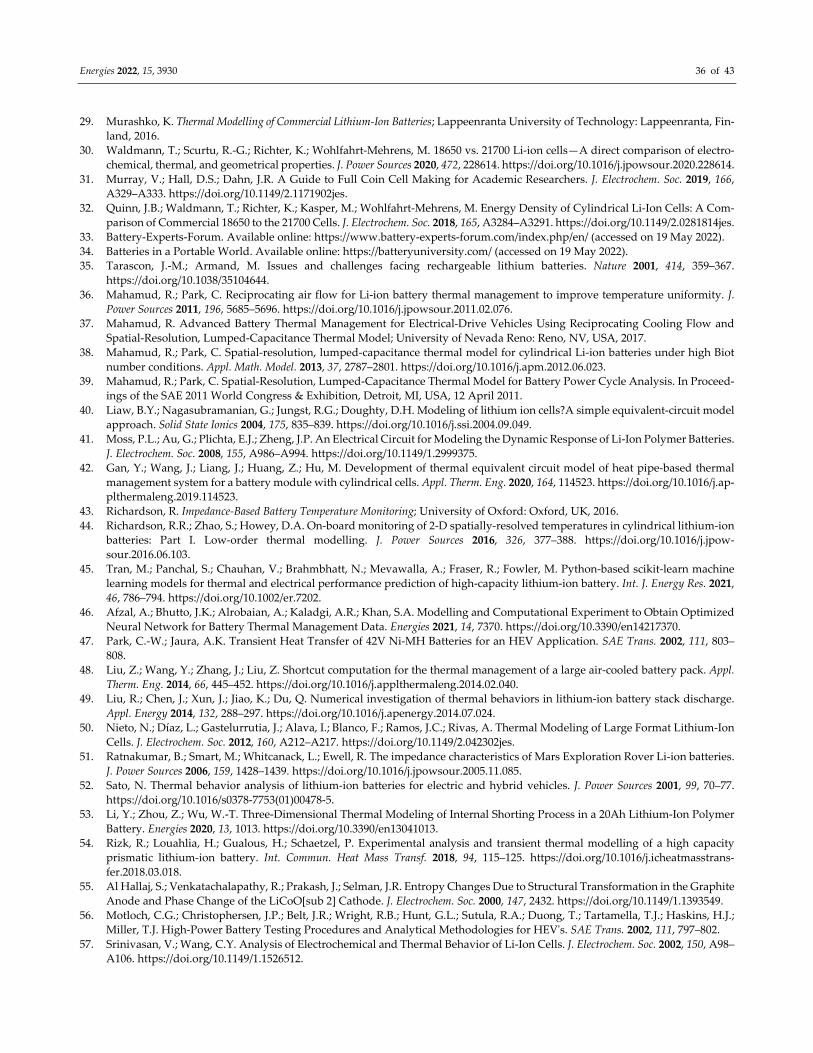
Energies 2022, 15, 3930 36 of 43
29. Murashko, K. Thermal Modelling of Commercial Lithium‐Ion Batteries; Lappeenranta University of Technology: Lappeenranta, Fin‐
land, 2016.
30. Waldmann, T.; Scurtu, R.‐G.; Richter, K.; Wohlfahrt‐Mehrens, M. 18650 vs. 21700 Li‐ion cells—A direct comparison of electro‐
chemical, thermal, and geometrical properties. J. Power Sources 2020, 472, 228614. https://doi.org/10.1016/j.jpowsour.2020.228614.
31. Murray, V.; Hall, D.S.; Dahn, J.R. A Guide to Full Coin Cell Making for Academic Researchers. J. Electrochem. Soc. 2019, 166,
A329–A333. https://doi.org/10.1149/2.1171902jes.
32. Quinn, J.B.; Waldmann, T.; Richter, K.; Kasper, M.; Wohlfahrt‐Mehrens, M. Energy Density of Cylindrical Li‐Ion Cells: A Com‐
parison of Commercial 18650 to the 21700 Cells. J. Electrochem. Soc. 2018, 165, A3284–A3291. https://doi.org/10.1149/2.0281814jes.
33. Battery‐Experts‐Forum. Available online: https://www.battery‐experts‐forum.com/index.php/en/ (accessed on 19 May 2022).
34. Batteries in a Portable World. Available online: https://batteryuniversity.com/ (accessed on 19 May 2022).
35. Tarascon, J.‐M.; Armand, M. Issues and challenges facing rechargeable lithium batteries. Nature 2001, 414, 359–367.
https://doi.org/10.1038/35104644.
36. Mahamud, R.; Park, C. Reciprocating air flow for Li‐ion battery thermal management to improve temperature uniformity. J.
Power Sources 2011, 196, 5685–5696. https://doi.org/10.1016/j.jpowsour.2011.02.076.
37. Mahamud, R. Advanced Battery Thermal Management for Electrical‐Drive Vehicles Using Reciprocating Cooling Flow and
Spatial‐Resolution, Lumped‐Capacitance Thermal Model; University of Nevada Reno: Reno, NV, USA, 2017.
38. Mahamud, R.; Park, C. Spatial‐resolution, lumped‐capacitance thermal model for cylindrical Li‐ion batteries under high Biot
number conditions. Appl. Math. Model. 2013, 37, 2787–2801. https://doi.org/10.1016/j.apm.2012.06.023.
39. Mahamud, R.; Park, C. Spatial‐Resolution, Lumped‐Capacitance Thermal Model for Battery Power Cycle Analysis. In Proceed‐
ings of the SAE 2011 World Congress & Exhibition, Detroit, MI, USA, 12 April 2011.
40. Liaw, B.Y.; Nagasubramanian, G.; Jungst, R.G.; Doughty, D.H. Modeling of lithium ion cells?A simple equivalent‐circuit model
approach. Solid State Ionics 2004, 175, 835–839. https://doi.org/10.1016/j.ssi.2004.09.049.
41. Moss, P.L.; Au, G.; Plichta, E.J.; Zheng, J.P. An Electrical Circuit for Modeling the Dynamic Response of Li‐Ion Polymer Batteries.
J. Electrochem. Soc. 2008, 155, A986–A994. https://doi.org/10.1149/1.2999375.
42. Gan, Y.; Wang, J.; Liang, J.; Huang, Z.; Hu, M. Development of thermal equivalent circuit model of heat pipe‐based thermal
management system for a battery module with cylindrical cells. Appl. Therm. Eng. 2020, 164, 114523. https://doi.org/10.1016/j.ap‐
plthermaleng.2019.114523.
43. Richardson, R. Impedance‐Based Battery Temperature Monitoring; University of Oxford: Oxford, UK, 2016.
44. Richardson, R.R.; Zhao, S.; Howey, D.A. On‐board monitoring of 2‐D spatially‐resolved temperatures in cylindrical lithium‐ion
batteries: Part I. Low‐order thermal modelling. J. Power Sources 2016, 326, 377–388. https://doi.org/10.1016/j.jpow‐
sour.2016.06.103.
45. Tran, M.; Panchal, S.; Chauhan, V.; Brahmbhatt, N.; Mevawalla, A.; Fraser, R.; Fowler, M. Python‐based scikit‐learn machine
learning models for thermal and electrical performance prediction of high‐capacity lithium‐ion battery. Int. J. Energy Res. 2021,
46, 786–794. https://doi.org/10.1002/er.7202.
46. Afzal, A.; Bhutto, J.K.; Alrobaian, A.; Kaladgi, A.R.; Khan, S.A. Modelling and Computational Experiment to Obtain Optimized
Neural Network for Battery Thermal Management Data. Energies 2021, 14, 7370. https://doi.org/10.3390/en14217370.
47. Park, C.‐W.; Jaura, A.K. Transient Heat Transfer of 42V Ni‐MH Batteries for an HEV Application. SAE Trans. 2002, 111, 803–
808.
48. Liu, Z.; Wang, Y.; Zhang, J.; Liu, Z. Shortcut computation for the thermal management of a large air‐cooled battery pack. Appl.
Therm. Eng. 2014, 66, 445–452. https://doi.org/10.1016/j.applthermaleng.2014.02.040.
49. Liu, R.; Chen, J.; Xun, J.; Jiao, K.; Du, Q. Numerical investigation of thermal behaviors in lithium‐ion battery stack discharge.
Appl. Energy 2014, 132, 288–297. https://doi.org/10.1016/j.apenergy.2014.07.024.
50. Nieto, N.; Díaz, L.; Gastelurrutia, J.; Alava, I.; Blanco, F.; Ramos, J.C.; Rivas, A. Thermal Modeling of Large Format Lithium‐Ion
Cells. J. Electrochem. Soc. 2012, 160, A212–A217. https://doi.org/10.1149/2.042302jes.
51. Ratnakumar, B.; Smart, M.; Whitcanack, L.; Ewell, R. The impedance characteristics of Mars Exploration Rover Li‐ion batteries.
J. Power Sources 2006, 159, 1428–1439. https://doi.org/10.1016/j.jpowsour.2005.11.085.
52. Sato, N. Thermal behavior analysis of lithium‐ion batteries for electric and hybrid vehicles. J. Power Sources 2001, 99, 70–77.
https://doi.org/10.1016/s0378‐7753(01)00478‐5.
53. Li, Y.; Zhou, Z.; Wu, W.‐T. Three‐Dimensional Thermal Modeling of Internal Shorting Process in a 20Ah Lithium‐Ion Polymer
Battery. Energies 2020, 13, 1013. https://doi.org/10.3390/en13041013.
54. Rizk, R.; Louahlia, H.; Gualous, H.; Schaetzel, P. Experimental analysis and transient thermal modelling of a high capacity
prismatic lithium‐ion battery. Int. Commun. Heat Mass Transf. 2018, 94, 115–125. https://doi.org/10.1016/j.icheatmasstrans‐
fer.2018.03.018.
55. Al Hallaj, S.; Venkatachalapathy, R.; Prakash, J.; Selman, J.R. Entropy Changes Due to Structural Transformation in the Graphite
Anode and Phase Change of the LiCoO[sub 2] Cathode. J. Electrochem. Soc. 2000, 147, 2432. https://doi.org/10.1149/1.1393549.
56. Motloch, C.G.; Christophersen, J.P.; Belt, J.R.; Wright, R.B.; Hunt, G.L.; Sutula, R.A.; Duong, T.; Tartamella, T.J.; Haskins, H.J.;
Miller, T.J. High‐Power Battery Testing Procedures and Analytical Methodologies for HEVʹs. SAE Trans. 2002, 111, 797–802.
57. Srinivasan, V.; Wang, C.Y. Analysis of Electrochemical and Thermal Behavior of Li‐Ion Cells. J. Electrochem. Soc. 2002, 150, A98–
A106. https://doi.org/10.1149/1.1526512.
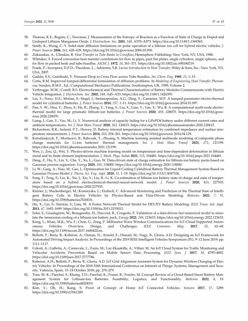
Energies 2022, 15, 3930 37 of 43
58. Thomas, K.E.; Bogatu, C.; Newman, J. Measurement of the Entropy of Reaction as a Function of State of Charge in Doped and
Undoped Lithium Manganese Oxide. J. Electrochem. Soc. 2001, 148, A570–A575. https://doi.org/10.1149/1.1369365.
59. Smith, K.; Wang, C.‐Y. Solid‐state diffusion limitations on pulse operation of a lithium ion cell for hybrid electric vehicles. J.
Power Sources 2006, 161, 628–639. https://doi.org/10.1016/j.jpowsour.2006.03.050.
60. Zukauskas, A.; Ulinskas, R. Heat Transfer in Tube Banks in Crossflow; Hemisphere Publishing: New York, NY, USA, 1988.
61. Whitaker, S. Forced convection heat transfer correlations for flow in pipes, past flat plates, single cylinders, single spheres, and
for flow in packed beds and tube bundles. AIChE J. 1972, 18, 361–371. https://doi.org/10.1002/aic.690180219.
62. Frank, P.; Incropera, D.P.D.; Theodore, L.; Adrienne, S.B. Lavine Introduction to Heat Transfer; Wiley & Sons, Inc.: New York, NY,
USA, 2007.
63. Gaddis, E.S.; Gnielinski, V. Pressure Drop in Cross Flow across Tube Bundles. Int. Chem. Eng. 1985, 25, 1–15.
64. Cotta, R.M. Improved lumped‐differential formulation of diffusion problems. In Modeling of Engineering Heat Transfer Phenom‐
ena; Sunden, B.M.F., Ed.; Computational Mechanics Publications: Southampton, UK, 1999; Volume 2.
65. Verbrugge, M.W.; Conell, R.S. Electrochemical and Thermal Characterization of Battery Modules Commensurate with Electric
Vehicle Integration. J. Electrochem. Soc. 2002, 149, A45–A53. https://doi.org/10.1149/1.1426395.
66. Lin, X.; Perez, H.E.; Mohan, S.; Siegel, J.; Stefanopoulou, A.G.; Ding, Y.; Castanier, M.P. A lumped‐parameter electro‐thermal
model for cylindrical batteries. J. Power Sources 2014, 257, 1–11. https://doi.org/10.1016/j.jpowsour.2014.01.097.
67. Pan, Y.‐W.; Hua, Y.; Zhou, S.; He, R.; Zhang, Y.; Yang, S.; Liu, X.; Lian, Y.; Yan, X.; Wu, B. A computational multi‐node electro‐
thermal model for large prismatic lithium‐ion batteries. J. Power Sources 2020, 459, 228070. https://doi.org/10.1016/j.jpow‐
sour.2020.228070.
68. Liang, J.; Gan, Y.; Yao, M.; Li, Y. Numerical analysis of capacity fading for a LiFePO4 battery under different current rates and
ambient temperatures. Int. J. Heat Mass Transf. 2020, 165, 120615. https://doi.org/10.1016/j.ijheatmasstransfer.2020.120615.
69. Richardson, R.R.; Ireland, P.T.; Howey, D. Battery internal temperature estimation by combined impedance and surface tem‐
perature measurement. J. Power Sources 2014, 265, 254–261. https://doi.org/10.1016/j.jpowsour.2014.04.129.
70. Kolodziejczyk, F.; Mortazavi, B.; Rabczuk, T.; Zhuang, X. Machine learning assisted multiscale modeling of composite phase
change materials for Li‐ion batteries’ thermal management. Int. J. Heat Mass Transf. 2021, 172, 121199.
https://doi.org/10.1016/j.ijheatmasstransfer.2021.121199.
71. Wen, J.; Zou, Q.; Wei, Y. Physics‐driven machine learning model on temperature and time‐dependent deformation in lithium
metal and its finite element implementation. J. Mech. Phys. Solids 2021, 153, 104481. https://doi.org/10.1016/j.jmps.2021.104481.
72. Deng, Z.; Hu, X.; Lin, X.; Che, Y.; Xu, L.; Guo, W. Data‐driven state of charge estimation for lithium‐ion battery packs based on
Gaussian process regression. Energy 2020, 205, 118000. https://doi.org/10.1016/j.energy.2020.118000.
73. Li, W.; Garg, A.; Xiao, M.; Gao, L. Optimization for Liquid Cooling Cylindrical Battery Thermal Management System Based on
Gaussian Process Model. J. Therm. Sci. Eng. Appl. 2020, 13, 1–19. https://doi.org/10.1115/1.4047526.
74. Feng, F.; Teng, S.; Liu, K.; Xie, J.; Xie, Y.; Liu, B.; Li, K. Co‐estimation of lithium‐ion battery state of charge and state of temper‐
ature based on a hybrid electrochemical‐thermal‐neural‐network model. J. Power Sources 2020, 455, 227935.
https://doi.org/10.1016/j.jpowsour.2020.227935.
75. Kleiner, J.; Stuckenberger, M.; Komsiyska, L.; Endisch, C. Advanced Monitoring and Prediction of the Thermal State of Intelli‐
gent Battery Cells in Electric Vehicles by Physics‐Based and Data‐Driven Modeling. Batteries 2021, 7, 31.
https://doi.org/10.3390/batteries7020031.
76. Hu, X.; Lin, S.; Stanton, S.; Lian, W. A Foster Network Thermal Model for HEV/EV Battery Modeling. IEEE Trans. Ind. Appl.
2011, 47, 1692–1699. https://doi.org/10.1109/tia.2011.2155012.
77. Solai, E.; Guadagnini, M.; Beaugendre, H.; Daccord, R.; Congedo, P. Validation of a data‐driven fast numerical model to simu‐
late the immersion cooling of a lithium‐ion battery pack. Energy 2022, 249, 123633. https://doi.org/10.1016/j.energy.2022.123633.
78. Kong, L.; Khan, M.K.; Wu, F.; Chen, G.; Zeng, P. Millimeter‐Wave Wireless Communications for IoT‐Cloud Supported Auton‐
omous Vehicles: Overview, Design, and Challenges. IEEE Commun. Mag. 2017, 55, 62–68.
https://doi.org/10.1109/mcom.2017.1600422cm.
79. Bellotti, F.; Berta, R.; Kobeissi, A.; Osman, N.; Arnold, E.; Dianati, M.; Nagy, B.; Gloria, A.D. Designing an IoT Framework for
Automated Driving Impact Analysis. In Proceedings of the 2019 IEEE Intelligent Vehicles Symposium (IV), 9–12 June 2019; pp.
1111–1117.
80. Celesti, A.; Galletta, A.; Carnevale, L.; Fazio, M.; Lay‐Ekuakille, A.; Villari, M. An IoT Cloud System for Traffic Monitoring and
Vehicular Accidents Prevention Based on Mobile Sensor Data Processing. IEEE Sens. J. 2017, 18, 4795–4802.
https://doi.org/10.1109/jsen.2017.2777786.
81. Kobeissi, A.H.; Bellotti, F.; Berta, R.; Gloria, A.D. IoT Grid Alignment Assistant System for Dynamic Wireless Charging of Elec‐
tric Vehicles. In Proceedings of the 2018 Fifth International Conference on Internet of Things: Systems, Management and Secu‐
rity, Valencia, Spain, 15–18 October 2018; pp. 274–279.
82. Tran, M.‐K.; Panchal, S.; Khang, T.D.; Panchal, K.; Fraser, R.; Fowler, M. Concept Review of a Cloud‐Based Smart Battery Man‐
agement System for Lithium‐Ion Batteries: Feasibility, Logistics, and Functionality. Batteries 2022, 8, 19.
https://doi.org/10.3390/batteries8020019.
83. Kim, Y.; Oh, H.; Kang, S. Proof of Concept of Home IoT Connected Vehicles. Sensors 2017, 17, 1289.
https://doi.org/10.3390/s17061289.

Energies 2022, 15, 3930 38 of 43
84. Shabani, B.; Biju, M. Theoretical Modelling Methods for Thermal Management of Batteries. Energies 2015, 8, 10153–10177.
https://doi.org/10.3390/en80910153.
85. Pesaran, A.A.; Burch, S.; Keyser, M. An Approach for Designing Thermal Management Systems for Electric and Hybrid Vehicle
Battery Packs. In Proceedings of the Fourth Vehicle Thermal Management Systems Conference and Exhibition, London, UK,
24–27 May 1999.
86. Wang, T.; Tseng, K.; Zhao, J.; Wei, Z. Thermal investigation of lithium‐ion battery module with different cell arrangement
structures and forced air‐cooling strategies. Appl. Energy 2014, 134, 229–238. https://doi.org/10.1016/j.apenergy.2014.08.013.
87. Yang, N.; Zhang, X.; Li, G.; Hua, D. Assessment of the forced air‐cooling performance for cylindrical lithium‐ion battery packs:
A comparative analysis between aligned and staggered cell arrangements. Appl. Therm. Eng. 2015, 80, 55–65.
https://doi.org/10.1016/j.applthermaleng.2015.01.049.
88. Yang, T.; Yang, N.; Zhang, X.; Li, G. Investigation of the thermal performance of axial‐flow air cooling for the lithium‐ion battery
pack. Int. J. Therm. Sci. 2016, 108, 132–144. https://doi.org/10.1016/j.ijthermalsci.2016.05.009.
89. Afzal, A.; Samee, A.D.M.; Razak, R.K.A.; Ramis, M.K. Effect of spacing on thermal performance characteristics of Li‐ion battery
cells. J. Therm. Anal. 2018, 135, 1797–1811. https://doi.org/10.1007/s10973‐018‐7664‐2.
90. Afzal, A.; Mujeebu, M.A. Thermo‐Mechanical and Structural Performances of Automobile Disc Brakes: A Review of Numerical
and Experimental Studies. Arch. Comput. Methods Eng. 2018, 26, 1489–1513. https://doi.org/10.1007/s11831‐018‐9279‐y.
91. Park, S.; Jung, D. Battery cell arrangement and heat transfer fluid effects on the parasitic power consumption and the cell tem‐
perature distribution in a hybrid electric vehicle. J. Power Sources 2013, 227, 191–198. https://doi.org/10.1016/j.jpow‐
sour.2012.11.039.
92. Sun, H.; Dixon, R. Development of cooling strategy for an air cooled lithium‐ion battery pack. J. Power Sources 2014, 272, 404–
414. https://doi.org/10.1016/j.jpowsour.2014.08.107.
93. Chen, K.; Wang, S.; Song, M.; Chen, L. Structure optimization of parallel air‐cooled battery thermal management system. Int. J.
Heat Mass Transf. 2017, 111, 943–952. https://doi.org/10.1016/j.ijheatmasstransfer.2017.04.026.
94. Jiaqiang, E.; Yue, M.; Chen, J.; Zhu, H.; Deng, Y.; Zhu, Y.; Zhang, F.; Wen, M.; Zhang, B.; Kang, S. Effects of the different air
cooling strategies on cooling performance of a lithium‐ion battery module with baffle. Appl. Therm. Eng. 2018, 144, 231–241.
https://doi.org/10.1016/j.applthermaleng.2018.08.064.
95. Shahid, S.; Agelin‐Chaab, M. Development and analysis of a technique to improve air‐cooling and temperature uniformity in a
battery pack for cylindrical batteries. Therm. Sci. Eng. Prog. 2018, 5, 351–363. https://doi.org/10.1016/j.tsep.2018.01.003.
96. Hong, S.; Zhang, X.; Chen, K.; Wang, S. Design of flow configuration for parallel air‐cooled battery thermal management system
with secondary vent. Int. J. Heat Mass Transf. 2018, 116, 1204–1212. https://doi.org/10.1016/j.ijheatmasstransfer.2017.09.092.
97. Zhao, G.; Wang, X.; Negnevitsky, M.; Zhang, H. A review of air‐cooling battery thermal management systems for electric and
hybrid electric vehicles. J. Power Sources 2021, 501, 230001. https://doi.org/10.1016/j.jpowsour.2021.230001.
98. Behi, H.; Karimi, D.; Behi, M.; Ghanbarpour, M.; Jaguemont, J.; Sokkeh, M.A.; Gandoman, F.H.; Berecibar, M.; Van Mierlo, J. A
new concept of thermal management system in Li‐ion battery using air cooling and heat pipe for electric vehicles. Appl. Therm.
Eng. 2020, 174, 115280. https://doi.org/10.1016/j.applthermaleng.2020.115280.
99. Yi, J.; Koo, B.; Shin, C.B.; Han, T.; Park, S. Modeling the effect of aging on the electrical and thermal behaviors of a lithium‐ion
battery during constant current charge and discharge cycling. Comput. Chem. Eng. 2017, 99, 31–39.
https://doi.org/10.1016/j.compchemeng.2017.01.006.
100. Cho, G.Y.; Choi, J.W.; Park, J.H.; Cha, S.W. Transient modeling and validation of lithium ion battery pack with air cooled ther‐
mal management system for electric vehicles. Int. J. Automot. Technol. 2014, 15, 795–803. https://doi.org/10.1007/s12239‐014‐0083‐
x.
101. Fan, Y.; Bao, Y.; Ling, C.; Chu, Y.; Tan, X.; Yang, S. Experimental study on the thermal management performance of air cooling
for high energy density cylindrical lithium‐ion batteries. Appl. Therm. Eng. 2019, 155, 96–109. https://doi.org/10.1016/j.ap‐
plthermaleng.2019.03.157.
102. Liu, Y.; Zhang, J. Design a J‐type air‐based battery thermal management system through surrogate‐based optimization. Appl.
Energy 2019, 252, 113426. https://doi.org/10.1016/j.apenergy.2019.113426.
103. He, H.; Jia, H.; Huo, W.; Sun, F. Field Synergy Analysis and Optimization of the Thermal Behavior of Lithium Ion Battery Packs.
Energies 2017, 10, 81. https://doi.org/10.3390/en10010081.
104. Xu, X.; He, R. Research on the heat dissipation performance of battery pack based on forced air cooling. J. Power Sources 2013,
240, 33–41. https://doi.org/10.1016/j.jpowsour.2013.03.004.
105. Wang, T.; Tseng, K.; Zhao, J. Development of efficient air‐cooling strategies for lithium‐ion battery module based on empirical
heat source model. Appl. Therm. Eng. 2015, 90, 521–529. https://doi.org/10.1016/j.applthermaleng.2015.07.033.
106. Saw, B.; Ye, Y.; Tay, A.A.; Chong, W.T.; Kuan, S.H.; Yew, M.C. Computational fluid dynamic and thermal analysis of Lithium‐
ion battery pack with air cooling. Appl. Energy 2016, 177, 783–792. https://doi.org/10.1016/j.apenergy.2016.05.122.
107. Erb, D.; Kumar, S.; Carlson, E.; Ehrenberg, I.; Sarma, S. Analytical methods for determining the effects of lithium‐ion cell size in
aligned air‐cooled battery packs. J. Energy Storage 2017, 10, 39–47. https://doi.org/10.1016/j.est.2016.12.003.
108. Shahid, S.; Agelin‐Chaab, M. Experimental and numerical studies on air cooling and temperature uniformity in a battery pack.
Int. J. Energy Res. 2018, 42, 2246–2262. https://doi.org/10.1002/er.4018.
109. Na, X.; Kang, H.; Wang, T.; Wang, Y. Reverse layered air flow for Li‐ion battery thermal management. Appl. Therm. Eng. 2018,
143, 257–262. https://doi.org/10.1016/j.applthermaleng.2018.07.080.
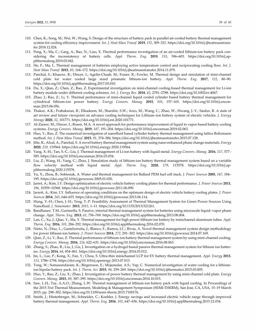
Energies 2022, 15, 3930 39 of 43
110. Chen, K.; Song, M.; Wei, W.; Wang, S. Design of the structure of battery pack in parallel air‐cooled battery thermal management
system for cooling efficiency improvement. Int. J. Heat Mass Transf. 2019, 132, 309–321. https://doi.org/10.1016/j.ijheatmasstrans‐
fer.2018.12.024.
111. Peng, X.; Ma, C.; Garg, A.; Bao, N.; Liao, X. Thermal performance investigation of an air‐cooled lithium‐ion battery pack con‐
sidering the inconsistency of battery cells. Appl. Therm. Eng. 2019, 153, 596–603. https://doi.org/10.1016/j.ap‐
plthermaleng.2019.03.042.
112. He, F.; Ma, L. Thermal management of batteries employing active temperature control and reciprocating cooling flow. Int. J.
Heat Mass Transf. 2015, 83, 164–172. https://doi.org/10.1016/j.ijheatmasstransfer.2014.11.079.
113. Panchal, S.; Khasow, R.; Dincer, I.; Agelin‐Chaab, M.; Fraser, R.; Fowler, M. Thermal design and simulation of mini‐channel
cold plate for water cooled large sized prismatic lithium‐ion battery. Appl. Therm. Eng. 2017, 122, 80–90.
https://doi.org/10.1016/j.applthermaleng.2017.05.010.
114. Du, X.; Qian, Z.; Chen, Z.; Rao, Z. Experimental investigation on mini‐channel cooling‐based thermal management for Li‐ion
battery module under different cooling schemes. Int. J. Energy Res. 2018, 42, 2781–2788. https://doi.org/10.1002/er.4067.
115. Zhao, J.; Rao, Z.; Li, Y. Thermal performance of mini‐channel liquid cooled cylinder based battery thermal management for
cylindrical lithium‐ion power battery. Energy Convers. Manag. 2015, 103, 157–165. https://doi.org/10.1016/j.encon‐
man.2015.06.056.
116. Thakur, A.K.; Prabakaran, R.; Elkadeem, M.; Sharshir, S.W.; Arıcı, M.; Wang, C.; Zhao, W.; Hwang, J.‐Y.; Saidur, R. A state of
art review and future viewpoint on advance cooling techniques for Lithium–ion battery system of electric vehicles. J. Energy
Storage 2020, 32, 101771. https://doi.org/10.1016/j.est.2020.101771.
117. Al‐Zareer, M.; Dincer, I.; Rosen, M.A. A novel approach for performance improvement of liquid to vapor based battery cooling
systems. Energy Convers. Manag. 2019, 187, 191–204. https://doi.org/10.1016/j.enconman.2019.02.063.
118. Huo, Y.; Rao, Z. The numerical investigation of nanofluid based cylinder battery thermal management using lattice Boltzmann
method. Int. J. Heat Mass Transf. 2015, 91, 374–384. https://doi.org/10.1016/j.ijheatmasstransfer.2015.07.128.
119. Jilte, R.; Afzal, A.; Panchal, S. A novel battery thermal management system using nano‐enhanced phase change materials. Energy
2020, 219, 119564. https://doi.org/10.1016/j.energy.2020.119564.
120. Yang, X.‐H.; Tan, S.‐C.; Liu, J. Thermal management of Li‐ion battery with liquid metal. Energy Convers. Manag. 2016, 117, 577–
585. https://doi.org/10.1016/j.enconman.2016.03.054.
121. Liu, Z.; Wang, H.; Yang, C.; Zhao, J. Simulation study of lithium‐ion battery thermal management system based on a variable
flow velocity method with liquid metal. Appl. Therm. Eng. 2020, 179, 115578. https://doi.org/10.1016/j.ap‐
plthermaleng.2020.115578.
122. Yu, X.; Zhou, B.; Sobiesiak, A. Water and thermal management for Ballard PEM fuel cell stack. J. Power Sources 2005, 147, 184–
195. https://doi.org/10.1016/j.jpowsour.2005.01.030.
123. Jarret, A.; Kim, I.Y. Design optimization of electric vehicle battery cooling plates for thermal performance. J. Power Sources 2011,
196, 10359–10368. https://doi.org/10.1016/j.jpowsour.2011.06.090.
124. Jarrett, A.; Kim, I.Y. Influence of operating conditions on the optimum design of electric vehicle battery cooling plates. J. Power
Sources 2014, 245, 644–655. https://doi.org/10.1016/j.jpowsour.2013.06.114.
125. Hung, Y.‐H.; Chen, J.‐H.; Teng, T.‐P. Feasibility Assessment of Thermal Management System for Green Power Sources Using
Nanofluid. J. Nanomater. 2013, 2013, 1–11. https://doi.org/10.1155/2013/321261.
126. Bandhauer, T.M.; Garimella, S. Passive, internal thermal management system for batteries using microscale liquid–vapor phase
change. Appl. Therm. Eng. 2013, 61, 756–769. https://doi.org/10.1016/j.applthermaleng.2013.08.004.
127. Lan, C.; Xu, J.; Qiao, Y.; Ma, Y. Thermal management for high power lithium‐ion battery by minichannel aluminum tubes. Appl.
Therm. Eng. 2016, 101, 284–292. https://doi.org/10.1016/j.applthermaleng.2016.02.070.
128. Nieto, N.; Díaz, L.; Gastelurrutia, J.; Blanco, F.; Ramos, J.C.; Rivas, A. Novel thermal management system design methodology
for power lithium‐ion battery. J. Power Sources 2014, 272, 291–302. https://doi.org/10.1016/j.jpowsour.2014.07.169.
129. Qian, Z.; Li, Y.; Rao, Z. Thermal performance of lithium‐ion battery thermal management system by using mini‐channel cooling.
Energy Convers. Manag. 2016, 126, 622–631. https://doi.org/10.1016/j.enconman.2016.08.063.
130. Zhang, S.; Zhao, R.; Liu, J.; Gu, J. Investigation on a hydrogel based passive thermal management system for lithium ion batter‐
ies. Energy 2014, 68, 854–861. https://doi.org/10.1016/j.energy.2014.03.012.
131. Jin, L.; Lee, P.; Kong, X.; Fan, Y.; Chou, S. Ultra‐thin minichannel LCP for EV battery thermal management. Appl. Energy 2013,
113, 1786–1794. https://doi.org/10.1016/j.apenergy.2013.07.013.
132. Tong, W.; Somasundaram, K.; Birgersson, E.; Mujumdar, A.S.; Yap, C. Numerical investigation of water cooling for a lithium‐
ion bipolar battery pack. Int. J. Therm. Sci. 2015, 94, 259–269. https://doi.org/10.1016/j.ijthermalsci.2015.03.005.
133. Huo, Y.; Rao, Z.; Liu, X.; Zhao, J. Investigation of power battery thermal management by using mini‐channel cold plate. Energy
Convers. Manag. 2015, 89, 387–395. https://doi.org/10.1016/j.enconman.2014.10.015.
134. Saw, L.H.; Tay, A.A.O.; Zhang, L.W. Thermal management of lithium‐ion battery pack with liquid cooling. In Proceedings of
the 2015 31st Thermal Measurement, Modeling & Management Symposium (SEMI‐THERM), San Jose, CA, USA, 15–19 March
2015; pp. 298–302. https://doi.org/10.1109/semi‐therm.2015.7100176.
135. Smith, J.; Hinterberger, M.; Schneider, C.; Koehler, J. Energy savings and increased electric vehicle range through improved
battery thermal management. Appl. Therm. Eng. 2016, 101, 647–656. https://doi.org/10.1016/j.applthermaleng.2015.12.034.

Energies 2022, 15, 3930 40 of 43
136. Chen, D.; Jiang, J.; Kim, G.‐H.; Yang, C.; Pesaran, A. Comparison of different cooling methods for lithium ion battery cells. Appl.
Therm. Eng. 2016, 94, 846–854. https://doi.org/10.1016/j.applthermaleng.2015.10.015.
137. Basu, S.; Hariharan, K.S.; Kolake, S.M.; Song, T.; Sohn, D.K.; Yeo, T. Coupled electrochemical thermal modelling of a novel Li‐
ion battery pack thermal management system. Appl. Energy 2016, 181, 1–13. https://doi.org/10.1016/j.apenergy.2016.08.049.
138. Mondal, B.; Lopez, C.F.; Mukherjee, P.P. Exploring the efficacy of nanofluids for lithium‐ion battery thermal management. Int.
J. Heat Mass Transf. 2017, 112, 779–794. https://doi.org/10.1016/j.ijheatmasstransfer.2017.04.130.
139. An, Z.; Jia, L.; Li, X.; Ding, Y. Experimental investigation on lithium‐ion battery thermal management based on flow boiling in
mini‐channel. Appl. Therm. Eng. 2017, 117, 534–543. https://doi.org/10.1016/j.applthermaleng.2017.02.053.
140. Gao, R.; Fan, Z.; Liu, S. A gradient channel‐based novel design of liquid‐cooled battery thermal management system for thermal
uniformity improvement. J. Energy Storage 2022, 48, 104014. https://doi.org/10.1016/j.est.2022.104014.
141. Khateeb, S.A.; Amiruddin, S.; Farid, M.; Selman, J.R.; Al‐Hallaj, S. Thermal management of Li‐ion battery with phase change
material for electric scooters: Experimental validation. J. Power Sources 2005, 142, 345–353. https://doi.org/10.1016/j.jpow‐
sour.2004.09.033.
142. Khateeb, S.A.; Farid, M.M.; Selman, J.R.; Al‐Hallaj, S. Design and simulation of a lithium‐ion battery with a phase change ma‐
terial thermal management system for an electric scooter. J. Power Sources 2004, 128, 292–307. https://doi.org/10.1016/j.jpow‐
sour.2003.09.070.
143. Al Hallaj, S.; Selman, J.R. Novel thermal management system for electric vehicle batteries using phase‐change material. J. Elec‐
trochem. Soc. 2000, 147, 3231–3236. https://doi.org/10.1149/1.1393888.
144. Qu, Z.; Li, W.; Tao, W. Numerical model of the passive thermal management system for high‐power lithium ion battery by
using porous metal foam saturated with phase change material. Int. J. Hydrogen Energy 2014, 39, 3904–3913.
https://doi.org/10.1016/j.ijhydene.2013.12.136.
145. Li, W.; Qu, Z.; He, Y.; Tao, Y. Experimental study of a passive thermal management system for high‐powered lithium ion bat‐
teries using porous metal foam saturated with phase change materials. J. Power Sources 2014, 255, 9–15.
https://doi.org/10.1016/j.jpowsour.2014.01.006.
146. Javani, N.; Dincer, I.; Naterer, G.; Rohrauer, G. Modeling of passive thermal management for electric vehicle battery packs with
PCM between cells. Appl. Therm. Eng. 2014, 73, 307–316. https://doi.org/10.1016/j.applthermaleng.2014.07.037.
147. Hémery, C.‐V.; Pra, F.; Robin, J.‐F.; Marty, P. Experimental performances of a battery thermal management system using a
phase change material. J. Power Sources 2014, 270, 349–358. https://doi.org/10.1016/j.jpowsour.2014.07.147.
148. Ling, Z.; Chen, J.; Fang, X.; Zhang, Z.; Xu, T.; Gao, X.; Wang, S. Experimental and numerical investigation of the application of
phase change materials in a simulative power batteries thermal management system. Appl. Energy 2014, 121, 104–113.
https://doi.org/10.1016/j.apenergy.2014.01.075.
149. Wang, Z.; Zhang, Z.; Jia, L.; Yang, L. Paraffin and paraffin/aluminum foam composite phase change material heat storage ex‐
perimental study based on thermal management of Li‐ion battery. Appl. Therm. Eng. 2015, 78, 428–436.
https://doi.org/10.1016/j.applthermaleng.2015.01.009.
150. Babapoor, A.; Azizi, M.; Karimi, G. Thermal management of a Li‐ion battery using carbon fiber‐PCM composites. Appl. Therm.
Eng. 2015, 82, 281–290. https://doi.org/10.1016/j.applthermaleng.2015.02.068.
151. Shirazi, A.H.N.; Mohebbi, F.; Kakavand, M.R.A.; He, B.; Rabczuk, T. Paraffin Nanocomposites for Heat Management of Lith‐
ium‐Ion Batteries: A Computational Investigation. J. Nanomater. 2016, 2016, 1–10. https://doi.org/10.1155/2016/2131946.
152. Rao, Z.; Wang, Q.; Huang, C.‐L. Investigation of the thermal performance of phase change material/mini‐channel coupled bat‐
tery thermal management system. Appl. Energy 2016, 164, 659–669. https://doi.org/10.1016/j.apenergy.2015.12.021.
153. Yang, Y.; Kuang, J.; Wang, H.; Song, G.; Liu, Y.; Tang, G. Enhancement in thermal property of phase change microcapsules with
modified silicon nitride for solar energy. Sol. Energy Mater. Sol. Cells 2016, 151, 89–95. https://doi.org/10.1016/j.sol‐
mat.2016.02.020.
154. Sun, Z.; Fan, R.; Yan, F.; Zhou, T.; Zheng, N. Thermal management of the lithium‐ion battery by the composite PCM‐Fin struc‐
tures. Int. J. Heat Mass Transf. 2019, 145, 118739. https://doi.org/10.1016/j.ijheatmasstransfer.2019.118739.
155. Hussain, A.; Tso, C.Y.; Chao, Y.H.C. Experimental investigation of a passive thermal management system for high‐powered
lithium ion batteries using nickel foam‐paraffin composite. Energy 2016, 115, 209–218. https://doi.org/10.1016/j.en‐
ergy.2016.09.008.
156. Alipanah, M.; Li, X. Numerical studies of lithium‐ion battery thermal management systems using phase change materials and
metal foams. Int. J. Heat Mass Transf. 2016, 102, 1159–1168. https://doi.org/10.1016/j.ijheatmasstransfer.2016.07.010.
157. Karimi, G.; Azizi, M.; Babapoor, A. Experimental study of a cylindrical lithium ion battery thermal management using phase
change material composites. J. Energy Storage 2016, 8, 168–174. https://doi.org/10.1016/j.est.2016.08.005.
158. Samimi, F.; Babapoor, A.; Azizi, M.; Karimi, G. Thermal management analysis of a Li‐ion battery cell using phase change ma‐
terial loaded with carbon fibers. Energy 2016, 96, 355–371. https://doi.org/10.1016/j.energy.2015.12.064.
159. Malik, M.; Dincer, I.; Rosen, M.A. Review on use of phase change materials in battery thermal management for electric and
hybrid electric vehicles. Int. J. Energy Res. 2016, 40, 1011–1031. https://doi.org/10.1002/er.3496.
160. Jiang, G.; Huang, J.; Fu, Y.; Cao, M.; Liu, M. Thermal optimization of composite phase change material/expanded graphite for
Li‐ion battery thermal management. Appl. Therm. Eng. 2016, 108, 1119–1125. https://doi.org/10.1016/j.ap‐
plthermaleng.2016.07.197.
Energies 2022, 15, 3930 41 of 43
161. Lv, Y.; Yang, X.; Li, X.; Zhang, G.; Wang, Z.; Yang, C. Experimental study on a novel battery thermal management technology
based on low density polyethylene‐enhanced composite phase change materials coupled with low fins. Appl. Energy 2016, 178,
376–382. https://doi.org/10.1016/j.apenergy.2016.06.058.
162. Wu, W.; Yang, X.; Zhang, G.; Ke, X.; Wang, Z.; Situ, W.; Li, X.; Zhang, J. An experimental study of thermal management system
using copper mesh‐enhanced composite phase change materials for power battery pack. Energy 2016, 113, 909–916.
https://doi.org/10.1016/j.energy.2016.07.119.
163. Azizi, Y.; Sadrameli, S. Thermal management of a LiFePO4 battery pack at high temperature environment using a composite of
phase change materials and aluminum wire mesh plates. Energy Convers. Manag. 2016, 128, 294–302. https://doi.org/10.1016/j.en‐
conman.2016.09.081.
164. Wu, W.; Yang, X.; Zhang, G.; Chen, K.; Wang, S. Experimental investigation on the thermal performance of heat pipe‐assisted
phase change material based battery thermal management system. Energy Convers. Manag. 2017, 138, 486–492.
https://doi.org/10.1016/j.enconman.2017.02.022.
165. Hao, M.; Li, J.; Park, S.; Moura, S.; Dames, C. Efficient thermal management of Li‐ion batteries with a passive interfacial thermal
regulator based on a shape memory alloy. Nat. Energy 2018, 3, 899–906. https://doi.org/10.1038/s41560‐018‐0243‐8.
166. Rodrigues, M.‐T.F.; Babu, G.; Gullapalli, H.; Kalaga, K.; Sayed, F.N.; Kato, K.; Joyner, J.; Ajayan, P.M. A materials perspective
on Li‐ion batteries at extreme temperatures. Nat. Energy 2017, 2, 1–14. https://doi.org/10.1038/nenergy.2017.108.
167. Wang, C.‐Y.; Zhang, G.; Ge, S.; Xu, T.; Ji, Y.; Yang, X.‐G.; Leng, Y. Lithium‐ion battery structure that self‐heats at low tempera‐
tures. Nature 2016, 529, 515–518. https://doi.org/10.1038/nature16502.
168. Zhang, S.; Xu, K.; Jow, T. A new approach toward improved low temperature performance of Li‐ion battery. Electrochem. Com‐
mun. 2002, 4, 928–932. https://doi.org/10.1016/s1388‐2481(02)00490‐3.
169. Vlahinos, A.; Pesaran, A.A. Energy Efficient Battery Heating in Cold Climates. SAE Trans. 2002, 111, 826–833.
https://doi.org/10.4271/2002‐01‐1975.
170. Viswanathan, V.V.; Choi, D.; Wang, D.; Xu, W.; Towne, S.; Williford, R.E.; Zhang, J.‐G.; Liu, J.; Yang, Z. Effect of entropy change
of lithium intercalation in cathodes and anodes on Li‐ion battery thermal management. J. Power Sources 2010, 195, 3720–3729.
https://doi.org/10.1016/j.jpowsour.2009.11.103.
171. Fleckenstein, M.; Bohlen, O.; Roscher, M.A.; Bäker, B. Current density and state of charge inhomogeneities in Li‐ion battery cells
with LiFePO4 as cathode material due to temperature gradients. J. Power Sources 2011, 196, 4769–4778.
https://doi.org/10.1016/j.jpowsour.2011.01.043.
172. Ning, G.; Haran, B.; Popov, B.N. Capacity fade study of lithium‐ion batteries cycled at high discharge rates. J. Power Sources
2003, 117, 160–169. https://doi.org/10.1016/s0378‐7753(03)00029‐6.
173. Doughty, D.H.; Roth, E.P. A General Discussion of Li Ion Battery Safety. Electrochem. Soc. Interface 2012, 21, 37–44.
https://doi.org/10.1149/2.f03122if.
174. Shi, T.; Dong, Y.; Wang, C.‐M.; Tao, F.; Chen, L. Enhanced cycle stability at high rate and excellent high rate capability of
La0.7Sr0.3Mn0.7Co0.3O3‐coated LiMn2O4. J. Power Sources 2014, 273, 959–965. https://doi.org/10.1016/j.jpowsour.2014.09.183.
175. Zhao, R.; Zhang, S.; Liu, J.; Gu, J. A review of thermal performance improving methods of lithium ion battery: Electrode modi‐
fication and thermal management system. J. Power Sources 2015, 299, 557–577. https://doi.org/10.1016/j.jpowsour.2015.09.001.
176. Loges, A.; Herberger, S.; Seegert, P.; Wetzel, T. A study on specific heat capacities of Li‐ion cell components and their influence
on thermal management. J. Power Sources 2016, 336, 341–350. https://doi.org/10.1016/j.jpowsour.2016.10.049.
177. Yang, X.‐G.; Zhang, G.; Ge, S.; Wang, C.‐Y. Fast charging of lithium‐ion batteries at all temperatures. Proc. Natl. Acad. Sci. USA
2018, 115, 7266–7271. https://doi.org/10.1073/pnas.1807115115.
178. Huang, Y.; Tang, Y.; Yuan, W.; Fang, G.; Yang, Y.; Zhang, X.; Wu, Y.; Yuan, Y.; Wang, C.; Li, J. Challenges and recent progress
in thermal management with heat pipes for lithium‐ion power batteries in electric vehicles. Sci. China Technol. Sci. 2021, 64, 919–
956. https://doi.org/10.1007/s11431‐020‐1714‐1.
179. Lee, G.G.; Choi, Y.H.; Park, C. Heat Managing Unit of High Voltage Battery. U.S. Patent 9,350,056, 24 May 2016.
180. Smith, J.; Singh, R.; Hinterberger, M.; Mochizuki, M. Battery thermal management system for electric vehicle using heat pipes.
Int. J. Therm. Sci. 2018, 134, 517–529. https://doi.org/10.1016/j.ijthermalsci.2018.08.022.
181. Greco, A.; Cao, D.; Jiang, X.; Yang, H. A theoretical and computational study of lithium‐ion battery thermal management for
electric vehicles using heat pipes. J. Power Sources 2014, 257, 344–355. https://doi.org/10.1016/j.jpowsour.2014.02.004.
182. Zhang, Z.; Wei, K. Experimental and numerical study of a passive thermal management system using flat heat pipes for lithium‐
ion batteries. Appl. Therm. Eng. 2020, 166, 114660. https://doi.org/10.1016/j.applthermaleng.2019.114660.
183. Gan, Y.; He, L.; Liang, J.; Tan, M.; Xiong, T.; Li, Y. A numerical study on the performance of a thermal management system for
a battery pack with cylindrical cells based on heat pipes. Appl. Therm. Eng. 2020, 179, 115740. https://doi.org/10.1016/j.ap‐
plthermaleng.2020.115740.
184. Qu, J.; Wang, C.; Li, X.; Wang, H. Heat transfer performance of flexible oscillating heat pipes for electric/hybrid‐electric vehicle
battery thermal management. Appl. Therm. Eng. 2018, 135, 1–9. https://doi.org/10.1016/j.applthermaleng.2018.02.045.
185. Rao, Z.; Wang, S.; Wu, M.; Lin, Z.; Li, F. Experimental investigation on thermal management of electric vehicle battery with heat
pipe. Energy Convers. Manag. 2013, 65, 92–97. https://doi.org/10.1016/j.enconman.2012.08.014.
186. Li, Y.; Guo, H.; Qi, F.; Guo, Z.; Li, M.; Tjernberg, L.B. Investigation on liquid cold plate thermal management system with heat
pipes for LiFePO4 battery pack in electric vehicles. Appl. Therm. Eng. 2020, 185, 116382. https://doi.org/10.1016/j.ap‐
plthermaleng.2020.116382.

Energies 2022, 15, 3930 42 of 43
187. Mbulu, H.; Laoonual, Y.; Wongwises, S. Experimental study on the thermal performance of a battery thermal management
system using heat pipes. Case Stud. Therm. Eng. 2021, 26, 101029. https://doi.org/10.1016/j.csite.2021.101029.
188. Nasir, F.M.; Abdullah, M.Z.; Ismail, M.A. Experimental Investigation of Water‐Cooled Heat Pipes in the Thermal Management
of Lithium‐Ion EV Batteries. Arab. J. Sci. Eng. 2019, 44, 7541–7552. https://doi.org/10.1007/s13369‐019‐03851‐5.
189. Wang, Q.; Jiang, B.; Xue, Q.; Sun, H.; Li, B.; Zou, H.; Yan, Y. Experimental investigation on EV battery cooling and heating by
heat pipes. Appl. Therm. Eng. 2014, 88, 54–60. https://doi.org/10.1016/j.applthermaleng.2014.09.083.
190. Putra, N.; Ariantara, B. Electric motor thermal management system using L‐shaped flat heat pipes. Appl. Therm. Eng. 2017, 126,
1156–1163. https://doi.org/10.1016/j.applthermaleng.2017.01.090.
191. Zhao, R.; Gu, J.; Liu, J. An experimental study of heat pipe thermal management system with wet cooling method for lithium
ion batteries. J. Power Sources 2015, 273, 1089–1097. https://doi.org/10.1016/j.jpowsour.2014.10.007.
192. Wang, J.; Gan, Y.; Liang, J.; Tan, M.; Li, Y. Sensitivity analysis of factors influencing a heat pipe‐based thermal management
system for a battery module with cylindrical cells. Appl. Therm. Eng. 2019, 151, 475–485. https://doi.org/10.1016/j.ap‐
plthermaleng.2019.02.036.
193. Liang, J.; Gan, Y.; Li, Y. Investigation on the thermal performance of a battery thermal management system using heat pipe
under different ambient temperatures. Energy Convers. Manag. 2018, 155, 1–9. https://doi.org/10.1016/j.enconman.2017.10.063.
194. Jiang, Z.; Qu, Z. Lithium–ion battery thermal management using heat pipe and phase change material during discharge–charge
cycle: A comprehensive numerical study. Appl. Energy 2019, 242, 378–392. https://doi.org/10.1016/j.apenergy.2019.03.043.
195. Tang, H.; Tang, Y.; Wan, Z.; Li, J.; Yuan, W.; Lu, L.; Li, Y.; Tang, K. Review of applications and developments of ultra‐thin micro
heat pipes for electronic cooling. Appl. Energy 2008, 223, 383‐400.
196. Jouhara, H.; Serey, N.; Khordehgah, N.; Bennett, R.; Almahmoud, S.; Lester, S.A.S.P. Investigation, development and experi‐
mental analyses of a heat pipe based battery thermal management system. Int. J. Thermofluids 2019, 1–2, 100004.
https://doi.org/10.1016/j.ijft.2019.100004.
197. Behi, H.; Behi, M.; Karimi, D.; Jaguemont, J.; Ghanbarpour, M.; Behnia, M.; Berecibar, M.; Van Mierlo, J. Heat pipe air‐cooled
thermal management system for lithium‐ion batteries: High power applications. Appl. Therm. Eng. 2021, 183, 116240.
https://doi.org/10.1016/j.applthermaleng.2020.116240.
198. Zhou, H.; Dai, C.; Liu, Y.; Fu, X.; Du, Y. Experimental investigation of battery thermal management and safety with heat pipe
and immersion phase change liquid. J. Power Sources 2020, 473, 228545. https://doi.org/10.1016/j.jpowsour.2020.228545.
199. Yao, M.; Gan, Y.; Liang, J.; Dong, D.; Ma, L.; Liu, J.; Luo, Q.; Li, Y. Performance simulation of a heat pipe and refrigerant‐based
lithium‐ion battery thermal management system coupled with electric vehicle air‐conditioning. Appl. Therm. Eng. 2021, 191,
116878. https://doi.org/10.1016/j.applthermaleng.2021.116878.
200. Chen, M.; Li, J. Nanofluid‐based pulsating heat pipe for thermal management of lithium‐ion batteries for electric vehicles. J.
Energy Storage 2020, 32, 101715. https://doi.org/10.1016/j.est.2020.101715.
201. Zhang, C.; Xia, Z.; Wang, B.; Gao, H.; Chen, S.; Zong, S.; Luo, K. A Li‐Ion Battery Thermal Management System Combining a
Heat Pipe and Thermoelectric Cooler. Energies 2020, 13, 841. https://doi.org/10.3390/en13040841.
202. Sakile, R.; Sinha, U.K. Estimation of Lithium‐Ion Battery State of Charge for Electric Vehicles Using an Adaptive Joint Algo‐
rithm. Adv. Theory Simul. 2022, 5, 2100397. https://doi.org/10.1002/adts.202100397.
203. Hu, X.; Sun, F.; Zou, Y. Estimation of State of Charge of a Lithium‐Ion Battery Pack for Electric Vehicles Using an Adaptive
Luenberger Observer. Energies 2010, 3, 1586–1603. https://doi.org/10.3390/en3091586.
204. Cen, J.; Jiang, F. Li‐ion power battery temperature control by a battery thermal management and vehicle cabin air conditioning
integrated system. Energy Sustain. Dev. 2020, 57, 141–148. https://doi.org/10.1016/j.esd.2020.06.004.
205. Buidin, T.; Mariasiu, F. Battery Thermal Management Systems: Current Status and Design Approach of Cooling Technologies.
Energies 2021, 14, 4879. https://doi.org/10.3390/en14164879.
206. Xu, J.; Zhang, C.; Wan, Z.; Chen, X.; Chan, S.H.; Tu, Z. Progress and perspectives of integrated thermal management systems in
PEM fuel cell vehicles: A review. Renew. Sustain. Energy Rev. 2021, 155, 111908. https://doi.org/10.1016/j.rser.2021.111908.
207. Tie, S.F.; Tan, C.W. A review of energy sources and energy management system in electric vehicles. Renew. Sustain. Energy Rev.
2013, 20, 82–102. https://doi.org/10.1016/j.rser.2012.11.077.
208. Lukic, S.M.; Wirasingha, S.G.; Rodriguez, F.; Cao, J.; Emadi, A. Power Management of an Ultracapacitor/Battery Hybrid Energy
Storage System in an HEV. In Proceedings of the IEEE Vehicle Power and Propulsion Conference, Windsor, UK, 6–8 September
2006; pp. 1–6.
209. Tan, K.M.; Ramachandaramurthy, V.K.; Yong, J.Y. Integration of electric vehicles in smart grid: A review on vehicle to grid
technologies and optimization techniques. Renew. Sustain. Energy Rev. 2016, 53, 720–732.
https://doi.org/10.1016/j.rser.2015.09.012.
210. Ahmad, A.; Alam, M.S.; Chabaan, R. A Comprehensive Review of Wireless Charging Technologies for Electric Vehicles. IEEE
Trans. Transp. Electrification 2017, 4, 38–63. https://doi.org/10.1109/tte.2017.2771619.
211. Araújo, R.E.; De Castro, R.; Pinto, C.; Melo, P.; Freitas, D. Combined Sizing and Energy Management in EVs With Batteries and
Supercapacitors. IEEE Trans. Veh. Technol. 2014, 63, 3062–3076. https://doi.org/10.1109/tvt.2014.2318275.
212. Patil, H.; Kalkhambkar, V.N. Grid Integration of Electric Vehicles for Economic Benefits: A Review. J. Mod. Power Syst. Clean
Energy 2021, 9, 13–26. https://doi.org/10.35833/mpce.2019.000326.
213. Arefifar, S.A.; Ordonez, M.; Ibrahim‐Mohamed, Y. Energy Management in Multi‐Microgrid Systems—Development and As‐
sessment. IEEE Trans. Power Syst. 2016, 32, 1. https://doi.org/10.1109/tpwrs.2016.2568858.

Energies 2022, 15, 3930 43 of 43
214. Hung, Y.‐H.; Wu, C.‐H. A combined optimal sizing and energy management approach for hybrid in‐wheel motors of EVs. Appl.
Energy 2015, 139, 260–271. https://doi.org/10.1016/j.apenergy.2014.11.028.
215. Zhang, R.; Cheng, X.; Yang, L. Flexible Energy Management Protocol for Cooperative EV‐to‐EV Charging. IEEE Trans. Intell.
Transp. Syst. 2018, 20, 172–184. https://doi.org/10.1109/tits.2018.2807184.
216. Van Der Meer, D.; Mouli, G.R.C.; Mouli, G.M.‐E.; Elizondo, L.R.; Bauer, P. Energy Management System with PV Power Forecast
to Optimally Charge EVs at the Workplace. IEEE Trans. Ind. Inform. 2016, 14, 311–320. https://doi.org/10.1109/tii.2016.2634624.
217. Vatanparvar, K.; Faruque, M.A.A. OTEM: Optimized Thermal and Energy Management for Hybrid Electrical Energy Storage
in Electric Vehicles. In Proceedings of the 2016 Design, Automation & Test in Europe Conference & Exhibition (DATE), Dresden,
Germany, 14–18 March 2016; pp. 19–24.
218. Lescot, J.; Sciarretta, A.; Chamaillard, Y.; Charlet, A. On the integration of optimal energy management and thermal manage‐
ment of hybrid electric vehicles. In Proceedings of the IEEE Vehicle Power and Propulsion Conference, Lille, France, 1–3 Sep‐
tember 2010; pp. 1–6.
219. Shams‐Zahraei, M.; Kouzani, A.Z.; Kutter, S.; Bäker, B. Integrated thermal and energy management of plug‐in hybrid electric
vehicles. J. Power Sources 2012, 216, 237–248. https://doi.org/10.1016/j.jpowsour.2012.05.055.
220. Zhang, L.; Yang, L.; Guo, X.; Yuan, X. Stage‐by‐phase multivariable combination control for centralized and distributed drive
modes switching of electric vehicles. Mech. Mach. Theory 2020, 147, 103752. https://doi.org/10.1016/j.mechmachthe‐
ory.2019.103752.
221. Wei, H.; Zhang, N.; Liang, J.; Ai, Q.; Zhao, W.; Huang, T.; Zhang, Y. Deep reinforcement learning based direct torque control
strategy for distributed drive electric vehicles considering active safety and energy saving performance. Energy 2021, 238,
121725. https://doi.org/10.1016/j.energy.2021.121725.
222. Boglou, V.; Karavas, C.; Karlis, A.; Arvanitis, K. An intelligent decentralized energy management strategy for the optimal elec‐
tric vehiclesʹ charging in low‐voltage islanded microgrids. Int. J. Energy Res. 2021, 46, 2988–3016. https://doi.org/10.1002/er.7358.
223. Chen, W.; Wang, J.; Yu, G.; Chen, J.; Hu, Y. Research on day‐ahead transactions between multi‐microgrid based on cooperative
game model. Appl. Energy 2022, 316, 119106. https://doi.org/10.1016/j.apenergy.2022.119106.
Related Documents