Theory and practice of elliptically bent x-ray mirrors Malcolm R. Howells, MEMBER SPIE Daniela Cambie Robert M. Duarte Steven Irick Alasdair A. MacDowell Howard A. Padmore Timothy R. Renner Lawrence Berkeley National Laboratory Advanced Light Source Berkeley, California 94720 E-mail: [email protected] Seungyu Rah Pohang University of Science and Technology Pohang 790-784, Korea Reubin Sandler Lawrence Berkeley National Laboratory Advanced Light Source Berkeley, California 94720 Abstract. We report the results of our research and development in techniques for producing elliptical x-ray mirrors by controlled bending of a flat substrate. We review the theory and technique of mirror bending with emphasis on the optical engineering issues and describe our design concepts for both metal and ceramic mirrors. We provide analysis of the various classes of error that must be addressed to obtain a high quality elliptical surface and a correspondingly fine focus of the x-ray beam. We describe particular mirrors that have been built, using these techniques, to meet the requirements of the scientific program at the Advanced Light Source at Lawrence Berkeley National Laboratory. For these examples, we show optical metrology results indicating the achievement of surface accuracy values around and, in some cases, below 1 mrad as well as x-ray measurements showing submicrometer focal spots. © 2000 Society of Photo-Optical Instrumentation Engineers. [S0091-3286(00)01410-0] Subject terms: synchrotron radiation; elliptical cylinder; mirror; adaptive; x-ray; microprobe. Paper 990303 received Aug. 2, 1999; revised manuscript received May 2, 2000; accepted for publication May 2, 2000. 1 Introduction Substantial progress has been made in recent years in the fabrication of high-quality x-ray mirror surfaces by conven- tional grinding and polishing. One of the beneficiaries of this improvement has been the synchrotron radiation re- search community, which is faced with the task of building optical systems for the latest generation of sychrotron x-ray sources such as the Advanced Light Source at Lawrence Berkeley National Laboratory. The new sources have sev- eral orders of magnitude higher x-ray brightness than older machines, and they have enabled many new types of x-ray spectroscopy, microscopy and microanalysis to be per- formed. These experiments have generated a demand for reflective condensing optics of high light-gathering power and excellent focus quality and we have been involved in studies over several years to provide such optics for the beam lines at the Advanced Light Source ~ALS!. The mir- rors of interest may be part of a prefocusing system that condenses the beam for some type of spectrometer or mi- croscope or they may form a microprobe delivering the beam directly to a micrometer- or submicrometer-scale spot on the sample. The simplest focusing surfaces that can be used for these systems are spheres and circular cylinders, and these are adequate for some purposes. However, to obtain simultaneously the finest focus and greatest light- gathering power it is always advantageous to use elliptical cylinder mirrors. Naturally, the realization of this advan- tage depends on being able to construct the mirror with sufficient accuracy and we address that issue in various ways in what follows. In this paper, we consider the technique of making el- liptical cylinder mirrors by bending an initially flat plate. We have adopted this approach over conventional rigid- mirror technology partly as a cost saving measure and partly in pursuit of a higher surface accuracy than could be achieved by zone polishing of a rigid substrate. Such ad- vantages follow in part from the use of classical flat polish- ing. We also report some of our experiences in engineering and operating mirrors of this type, ranging from a 1-m-class condenser mirror to small microprobe optics delivering submicrometer-scale focal spots. 2 Scientific Motivations and Requirements There are now microprobe or microfocus experiments in place at most of the third-generation synchrotron radiation laboratories. 1,2 A variety of focusing techniques have been used as reviewed, for example, by Dhez. In selecting the one best suited to the microfocus experiments at ALS, par- ticularly x-ray microdiffraction ~m-XRD!, fluorescence mi- croanalysis ~m-XRF! and x-ray photoelectron spectroscopy ~m-XPS!, we judged the need 3 for convenient wavelength tuning to be a very high priority. This favors the methods based on specular reflection and we believe that, of these, the elliptical Kirkpatrick-Baez mirror scheme 4 has the best flexibility and light-gathering power. In particular, either one or both members of the pair can be used for prefocus- ing or postfocusing with independent choice of magnifica- tion in the horizontal and vertical directions. We have now built and operated several elliptical Kirkpatrick-Baez sys- tems and we discuss the performances achieved so far and projected for the future in the sections that follow. How- ever, it is clear from the outset that, while a specular Kirkpatrick-Baez scheme is very competitive for tunability, light-gathering power and flux, it lags behind zone plates 2748 Opt. Eng. 39(10) 2748– 2762 (October 2000) 0091-3286/2000/$15.00 © 2000 Society of Photo-Optical Instrumentation Engineers

Welcome message from author
This document is posted to help you gain knowledge. Please leave a comment to let me know what you think about it! Share it to your friends and learn new things together.
Transcript
Theory and practice of elliptically bent x-raymirrors
Malcolm R. Howells, MEMBER SPIEDaniela CambieRobert M. DuarteSteven IrickAlasdair A. MacDowellHoward A. PadmoreTimothy R. RennerLawrence Berkeley National LaboratoryAdvanced Light SourceBerkeley, California 94720E-mail: [email protected]
Seungyu RahPohang University of Science and
TechnologyPohang 790-784, Korea
Reubin SandlerLawrence Berkeley National LaboratoryAdvanced Light SourceBerkeley, California 94720
Abstract. We report the results of our research and development intechniques for producing elliptical x-ray mirrors by controlled bending ofa flat substrate. We review the theory and technique of mirror bendingwith emphasis on the optical engineering issues and describe our designconcepts for both metal and ceramic mirrors. We provide analysis of thevarious classes of error that must be addressed to obtain a high qualityelliptical surface and a correspondingly fine focus of the x-ray beam. Wedescribe particular mirrors that have been built, using these techniques,to meet the requirements of the scientific program at the Advanced LightSource at Lawrence Berkeley National Laboratory. For these examples,we show optical metrology results indicating the achievement of surfaceaccuracy values around and, in some cases, below 1 mrad as well asx-ray measurements showing submicrometer focal spots. © 2000 Societyof Photo-Optical Instrumentation Engineers. [S0091-3286(00)01410-0]
Subject terms: synchrotron radiation; elliptical cylinder; mirror; adaptive; x-ray;microprobe.
Paper 990303 received Aug. 2, 1999; revised manuscript received May 2, 2000;accepted for publication May 2, 2000.
thn-ofre-
ngrayncev-
lder-raer-
d foerin
the
hatm
hepo
n berr,ht-
ican-ith
ious
el-.
id-ndbead-
ringss
ng
inionnthear-
y
dsese,
rus-a-ws-and-
lary,tes
1 Introduction
Substantial progress has been made in recent years infabrication of high-quality x-ray mirror surfaces by convetional grinding and polishing. One of the beneficiariesthis improvement has been the synchrotron radiationsearch community, which is faced with the task of buildioptical systems for the latest generation of sychrotron x-sources such as the Advanced Light Source at LawreBerkeley National Laboratory. The new sources have seral orders of magnitude higher x-ray brightness than omachines, and they have enabled many new types of xspectroscopy, microscopy and microanalysis to be pformed. These experiments have generated a demanreflective condensing optics of high light-gathering powand excellent focus quality and we have been involvedstudies over several years to provide such optics forbeam lines at the Advanced Light Source~ALS!. The mir-rors of interest may be part of a prefocusing system tcondenses the beam for some type of spectrometer orcroscope or they may form a microprobe delivering tbeam directly to a micrometer- or submicrometer-scale son the sample. The simplest focusing surfaces that caused for these systems are spheres and circular cylindand these are adequate for some purposes. Howeveobtain simultaneously the finest focus and greatest liggathering power it is always advantageous to use elliptcylinder mirrors. Naturally, the realization of this advatage depends on being able to construct the mirror wsufficient accuracy and we address that issue in varways in what follows.
In this paper, we consider the technique of makingliptical cylinder mirrors by bending an initially flat plate
2748 Opt. Eng. 39(10) 2748–2762 (October 2000) 0091-3286/2000/$
e
e
y
r
i-
tes,to
l
We have adopted this approach over conventional rigmirror technology partly as a cost saving measure apartly in pursuit of a higher surface accuracy than couldachieved by zone polishing of a rigid substrate. Suchvantages follow in part from the use of classicalflat polish-ing. We also report some of our experiences in engineeand operating mirrors of this type, ranging from a 1-m-clacondenser mirror to small microprobe optics deliverisubmicrometer-scale focal spots.
2 Scientific Motivations and Requirements
There are now microprobe or microfocus experimentsplace at most of the third-generation synchrotron radiatlaboratories.1,2 A variety of focusing techniques have beeused as reviewed, for example, by Dhez. In selectingone best suited to the microfocus experiments at ALS, pticularly x-ray microdiffraction~m-XRD!, fluorescence mi-croanalysis~m-XRF! and x-ray photoelectron spectroscop~m-XPS!, we judged the need3 for convenient wavelengthtuning to be a very high priority. This favors the methobased on specular reflection and we believe that, of ththe elliptical Kirkpatrick-Baez mirror scheme4 has the bestflexibility and light-gathering power. In particular, eitheone or both members of the pair can be used for prefocing or postfocusing with independent choice of magnifiction in the horizontal and vertical directions. We have nobuilt and operated several elliptical Kirkpatrick-Baez sytems and we discuss the performances achieved so farprojected for the future in the sections that follow. However, it is clear from the outset that, while a specuKirkpatrick-Baez scheme is very competitive for tunabilitlight-gathering power and flux, it lags behind zone pla
15.00 © 2000 Society of Photo-Optical Instrumentation Engineers
om
alstetchthi
mirror
thade
derap-fo
ronnt
icn-
ems ad
e
eirdueif-ispotnewap-ofesn-
dsthee
imi-nght
ie
cus
re ofyis
is
13bebe
Onan
illamare
heror-thede-lese-anerituct.
o-the
-
ee see sin
Howells et al.: Theory and practice of elliptically bent x-ray mirrors
with respect to spatial resolution by factors that range frabout 4 for hard x rays to more than 10 for soft x rays.
Apart from high spatial resolution, the other principrequirement of the scientific applications is to not waphotons. This requires attention to the phase-space maing of the beam and the optical system and we discussfurther in Section 4.
3 Technical Approach and History
We are interested in bending a flat constant-thicknessror by the application of unequal end couples. If the mirhas a constant width as well as constant thickness, thenresult of such bending is a cubic curve which can be mto approximate an ellipse up to third order@see Equation2!#. This enables correction of defocus and coma* whileleaving higher order aberrations uncorrected. Higher orcorrections to the bent shape are made, if required, byplying a controlled variation to the mirror width. Techniques of this general type have often been used beforeboth normal-incidence6 and grazing-incidence7–9 systemsand have been quite widely used for focusing synchrotradiation x rays.10–12 This has included the use of bemetal mirrors with water cooling,13 gravity-correctedmirrors14 and directly deformable piezocerammirrors.15,16 The programmable-width concept was first itroduced by Turner and Bennett17 and Underwood18 whilethe ALS group have developed a variable-thickness schin which the mirror and bending mechanism are built asingle monolith.19,20The situation as of 1993 was revieweby Howells and Lunt20 and more recent work at thALS2,21–24 and other third-generation light sources25–27 isnow on record.
Some of the mentioned mirrors have achieved thspecified performance levels, while others have failedto the application of unintended additional forces. The dficulty of applying the couples with sufficient accuracyincreasing at the present time due to the smaller focal sthat are being sought. In this paper, we describe someways to apply the couples via weak leaf springs. Thisproach makes it much simpler to control the amountbending with high accuracy and also lends itself to schemthat do not apply tensile forces to the mirror. We concetrate specifically on elliptical mirrors, although the methoof construction we will discuss are also applicable toquadratic~i.e., circular! and cubic approximations to thellipse.
4 Phase Space Acceptance of a GrazingIncidence X-Ray Mirror
Let us consider the quantitative effect of phase-space ltations, which apply to all focusing systems, includix-ray mirrors. Suppose a mirror is required to focus ligfrom a source of full widths at distancer to a spot of widths8 at distancer 8. The useful angles of grazing incidence lin the range zero touc ~the critical angle! so, in principal,the convergence angle for the beam arriving at the fo
*It has been pointed out by Underwood5 that the term coma should not bused to describe this aberration and that certain errors beyond mermantics can result from so doing. However, the usage has becomwidespread that it is now conventional. Thus we follow the conventionthis work.
-s
-
e
-
r
e
s
could be up to 2uc . However, in practice one can nevemake the mirror long enough to cover such a large rangangles and the limit is set by ther 8 values and the geometrof fitting in both mirrors of the pair. Roughly speaking, thlimits the mirror lengths to aboutr 8 and the convergenceangle to aboutuc/2. If the source angle isf and the focusedbeam angle isf8, thensf5s8f8 and theusableradiationemission angle is given byf5s8uc /(2s). For example,the size sH 3 sV of an ALS bending-magnet source240320 mm2. Therefore at 10 keV (uc'6 mrad), with a1-mm focused spot, 0.15 mrad of the vertical and 0.0mrad of the horizontal fans emitted by the source wouldusable. This shows that almost all of the vertical fan canused, which is a benefit of the high vertical brightness.the other hand, a smaller fraction of the horizontal fan cbe used implying that the horizontally focusing mirror wnormally be the shorter and therefore the downstremember of the pair. Some further examples of this typegiven by Howells and Hastings.28
The broad picture is that microprobe mirrors have ratsmall usable emission angles and utilize only a limited ption of the beam available at a bend magnet port. Onother hand, condenser mirrors are usually required toliver a larger spot~the size of an entrance slit or samptypically! and can usually accept the entire beam. Conquently microprobe mirrors are typically much smaller thcondensers. In the case of a microprobe, the figure of mis the resolving-power-phase-space-acceptance prodThe resolving power is proportional to 1/s8 and the accep-tance iss8f8. The figure of merit thus reduces tof8, orequivalently to the mirror size that indicates that micrprobe mirrors should be made as large as possible up tolimit set by the usable emission angle.
5 Geometrical Considerations
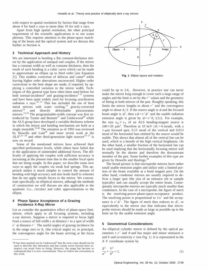
An elliptical cylinder mirror is defined by the optical parametersr ,r 8 and u and has major and minor semiaxesaandb and eccentricitye ~see Fig. 1!. It is represented in theX-Y coordinate system by
X2
a2 1Y2
b2 51. ~1!
-o
Fig. 1 Ellipse layout and notation.
2749Optical Engineering, Vol. 39 No. 10, October 2000
erie
on
e
twoeent
is-
o-
eof
he
nedde
de
ne.inis
ror
ctof
lue
use
sthe
ture
p toht-
p-
ching
Howells et al.: Theory and practice of elliptically bent x-ray mirrors
The same ellipse can also be represented by a power sin the x, y coordinates of Fig. 1 as follows:
y5a2x21a3x31a4x41 ¯ , ~2!
so that the slope and curvature are,
dy
dx52a2x13a3x214a4x31 ¯ ~3a!
d2y
dx2 52a216a3x112a4x21 ¯ . ~3b!
Theai coefficients for the ellipse are given up toa10 in theAppendix.29 Each termaix
i of the series in Equation~2!corresponds to an aberration of the reflected wave frwhich will be corrected if the term is faithfully built intothe mirror shape. Thei 52 term corresponds to defocus, thi 53 one to coma~see earlier footnote! @linear variation ofcurvature with position in the aperture~see Equation~3!#,the i 54 one to spherical aberration and so on.
The major and minor semiaxesa andb, the eccentricitye of the ellipse, the coordinates (X0 ,Y0) of the pole of themirror and the angled between theOX and ox axes arerelated to the optical parametersr ,r 8 andu by the follow-ing relations:
2a5r 1r 8, Y05rr 8 sin 2u
2ae,
~2ae!25r 21r 8222rr 8 cos 2u, udu5cos21 S sinu
e D ,
b25a2~12e2!, X056aAS 12Y0
2
b2 D ,
~4!
where the square root is1, zero or2 according asr .,5 or,r 8.
6 Formation of an Elliptical Surface by BeamBending
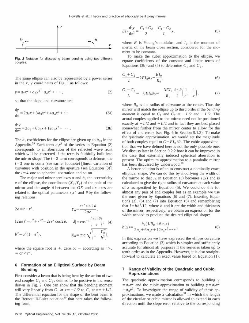
First consider a beam that is being bent by the action ofend couplesC1 andC2 , defined to be positive in the sensdrawn in Fig. 2. One can show that the bending momwill vary linearly from C1 at x52L/2 to C2 at x51L/2.The differential equation for the shape of the bent beamthe Bernouilli-Euler equation30 that here takes the following form,
Fig. 2 Notation for discussing beam bending using two differentcouples.
2750 Optical Engineering, Vol. 39 No. 10, October 2000
s
t
EI0
d2y
dx2 5C11C2
22
C12C2
Lx, ~5!
where E is Young’s modulus, andI 0 is the moment ofinertia of the beam cross section, considered for the mment to be constant.
To make the cubic approximation to the ellipse, wequate coefficients of the constant and linear termsEquations~3b! and ~5! to determineC1 andC2 .
C11C2
252EI0a25
EI0
R0, ~6!
C12C2
L526EI0a352
3EI0
R0
sinu
2 S 1
r 82
1
r D , ~7!
whereR0 is the radius of curvature at the center. Thus tmirror will match the ellipse up to third order if thebendingmomentis equal toC1 and C2 at 2L/2 and 1L/2. Theactual couples applied to the mirror need not be positioexactly at2L/2 and1L/2 and in fact they are best placesomewhat further from the mirror center to allow for theffect of end errors~see Fig. 6 in Section 9.1.3!. To makethe quadratic approximation, we would set the magnituof both couples equal toC5EI0 /R. The cubic approxima-tion that we have defined here is not the only possible oWe discuss later in Section 9.2.2 how it can be improvedthe case that externally induced spherical aberrationpresent. The optimum approximation to a parabolic mirhas been discussed by Underwood.18
A better solution is often to construct a nominally exaelliptical shape. We can do this by modifying the widththe mirror so thatI 0 in Equation~5! becomesI (x) and iscalculated to give the right radius of curvature at each vaof x as specified by Equation~5!. We could do this foralmost any pair of end couples but as an example wethe ones given by Equations~6! and ~7!. Inserting Equa-tions ~3!, ~6! and ~7! into Equation~5! and rememberingthat I 5bh3/12, whereb andh are the width and thicknesof the mirror, respectively, we obtain an expression forwidth needed to produce the desired elliptical shape:
b~x!5b0~1/R0 16a3x!
2a216a3x112a4x21¯
. ~8!
In this expression we have expressed the ellipse curvaaccording to Equation~3! which is simpler and sufficientlyaccurate for almost all purposes if the series is taken utenth order as in the Appendix. However, it is also straigforward to calculate an exact value based on Equation~1!.
7 Range of Validity of the Quadratic and CubicApproximations
The quadratic approximation corresponds to buildingy5a2x2 and the cubic approximation to buildingy5a2x2
1a3x3. To investigate the range of validity of these aproximations, we made a calculation31 in which the lengthof the circular or cubic mirror is allowed to extend in eadirection until the slope error relative to the correspond
Howells et al.: Theory and practice of elliptically bent x-ray mirrors
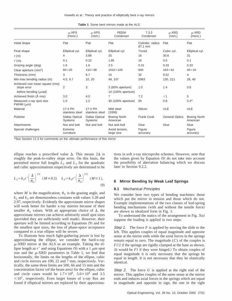
Table 1 Some bent mirrors made at the ALS.
m-XPS(Horiz.)
m-XPS(Vert.)
PEEMCondenser
7.3.3Condenser
m-XRD(Vert.)
m-XRD(Horiz.)
Initial shape Flat Flat Flat Cylinder, radius87.1 mm
Flat Flat
Final shape Elliptical cyl. Elliptical cyl. Elliptical cyl. Toroid Cubic cyl. Elliptical cyl.
r (m) 4 3.88 20 16 30.6 31
r8(m) 0.1 0.22 1.85 16 0.5 0.1
Grazing angle (deg) 1.6 1.6 2.5 0.31 0.33 0.33
Clear aperture (mm2) 60325 110338 10103100 600 163342 40310
Thickness (mm) 3 6.7 15 32 9.52 4
Min-max bending radius (m) 4.5, 9.7 10, 20 49, 107 2963 130, 211 28, 40
Achieved root mean square (rms)slope error 2 3 3 (60% aperture) 1.0 1.4 0.6
before bending (mrad) 14 (100% aperture)
Achieved finish (Å rms) 3.0 4.0 7 7.2 ,1 5
Measured x-ray spot sizeFWHM (mm)
1.0 1.2 30 (100% aperture) 50 0.8 0.4*
Material 17-4 PHstainless steel
17-4 PHstainless steel
Mild steel(1006)
Silicon ULE ULE
Polisher Dallas OpticalSystems
Dallas OpticalSystems
Boeing NorthAmerican
Frank Cook General Optics Boeing NorthAmerican
Attachments Nut and bolt Nut and bolt Nut and bolt Glue Glue Glue
Special challenges Extremecurvature
Avoid tension,large size
Figureaccuracy
Figureaccuracy
*See Section 11.3 for comments on the ultimate performance of this mirror.
the
be
andpesir
zes
tan
yayl-
ticer-the
rea-
hattss
oseot.ing
e
ngs
wn.
beally
qualht
ellipse reaches a prescribed valueD. This means 2D isroughly the peak-to-valley slope error. On this basis,permitted mirror full lengthsL2 and L3 for the quadraticand cubic approximations respectively are determined to
L25k2r 8S D
uGD 1/2
~M<0.5! L35k3r 8S D
uGD 1/3
~M<1!,
~9!
whereM is the magnification;uG is the grazing angle, andk2 andk3 are dimensionless constants with values 3.282.97, respectively. Evidently the approximate mirror shawill work better for harder x-ray mirrors because of thesmaller uG values. With an appropriate choice ofD, theapproximate mirrors can achieve arbitrarily small spot si~provided they are sufficiently well made!. However, theiraperture will be limited according to Equations~9! and forthe smallest spot sizes, the loss of phase-space accepcompared to a true ellipse will be severe.
To illustrate how much light-gathering power is lost bapproximating the ellipse, we consider the hard-x-rm-XRD mirror at the ALS as an example. Taking the elipse length asr 8 and using Equations~9! with a 1mm spotsize and them-XRD parameters in Table 1, we find thahorizontally, the limits on the lengths of the ellipse, cuband circle mirrors are 100, 22 and 7 mm, respectively. Vtically, the same three limits are 500, 66 and 15 mm andconcentration factor~of the beam area! for the ellipse, cubicand circle cases would be 1.73106, 5.03104 and 3.53103, respectively. Even larger losses of x-ray flux afound if elliptical mirrors are replaced by their approxim
ce
tions in soft x-ray microprobe schemes. However, note tthe values given by Equation~9! do not take into accounthe possibility of aberration balancing which we disculater in Section 9.2.2.
8 Mirror Bending by Weak Leaf Springs
8.1 Mechanical Principles
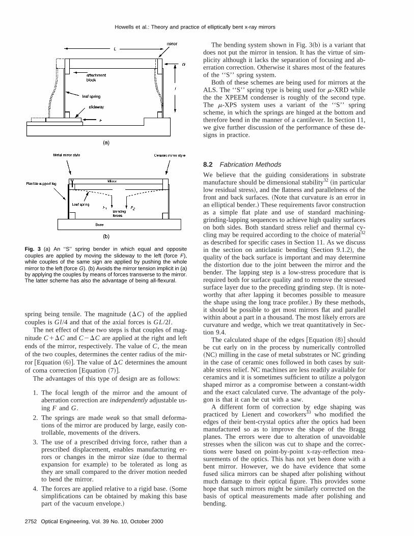
We consider here two types of bending machines: thwhich put the mirror in tension and those which do nExample implementations of the two classes of leaf-sprbending mechanisms~with and without the tensile force!are shown in idealized form in Fig. 3.
To understand the statics of the arrangement in Fig. 3~a!suppose the loading is applied in two steps:
Step 1. The forceF is applied by moving the slide to thleft. This applies couples of equal magnitude andoppositesense at the mirror ends while the axial forces in the spriremain equal to zero. The magnitude (C) of the couples isFl /2 if the springs are rigidly clamped at the base as sho~It would beFl if they were hinged.! To obtain couples ofequal magnitude it is only necessary that the springsequal in length. It is not necessary that they be elasticidentical.
Step 2. The forceG is applied at the right end of themirror. This applies couples of thesamesense at the mirrorends and induces axial forces in the springs which are ein magnitude and opposite in sign, the one in the rig
2751Optical Engineering, Vol. 39 No. 10, October 2000
ag-ft
ir-t
:
of
-n-
n aer
sed
se
m-b-res
the
pe.gand11,de-
ate
he
nng-cescy-luss
inehet issed
ure,llelareec-
ednguit-for
onidtholy-
s
eenaggblerrec-a-
th ameoutmetheand
Howells et al.: Theory and practice of elliptically bent x-ray mirrors
spring being tensile. The magnitude (DC) of the appliedcouples isGl/4 and that of the axial forces isGL/2l .
The net effect of these two steps is that couples of mnitudeC1DC andC2DC are applied at the right and leends of the mirror, respectively. The value ofC, the meanof the two couples, determines the center radius of the mror @Equation~6!#. The value ofDC determines the amounof coma correction@Equation~7!#.
The advantages of this type of design are as follows
1. The focal length of the mirror and the amountaberration correction areindependentlyadjustable us-ing F andG.
2. The springs are madeweak so that small deformations of the mirror are produced by large, easily cotrollable, movements of the drivers.
3. The use of a prescribed driving force, rather thaprescribed displacement, enables manufacturingrors or changes in the mirror size~due to thermalexpansion for example! to be tolerated as long athey are small compared to the driver motion needto bend the mirror.
4. The forces are applied relative to a rigid base.~Somesimplifications can be obtained by making this bapart of the vacuum envelope.!
Fig. 3 (a) An ‘‘S’’ spring bender in which equal and oppositecouples are applied by moving the slideway to the left (force F),while couples of the same sign are applied by pushing the wholemirror to the left (force G). (b) Avoids the mirror tension implicit in (a)by applying the couples by means of forces transverse to the mirror.The latter scheme has also the advantage of being all-flexural.
2752 Optical Engineering, Vol. 39 No. 10, October 2000
-
The bending system shown in Fig. 3~b! is a variant thatdoes not put the mirror in tension. It has the virtue of siplicity although it lacks the separation of focusing and aerration correction. Otherwise it shares most of the featuof the ‘‘S’’ spring system.
Both of these schemes are being used for mirrors atALS. The ‘‘S’’ spring type is being used form-XRD whilethe the XPEEM condenser is roughly of the second tyThe m-XPS system uses a variant of the ‘‘S’’ sprinscheme, in which the springs are hinged at the bottomtherefore bend in the manner of a cantilever. In Sectionwe give further discussion of the performance of thesesigns in practice.
8.2 Fabrication Methods
We believe that the guiding considerations in substrmanufacture should be dimensional stability32 ~in particularlow residual stress!, and the flatness and parallelness of tfront and back surfaces.~Note that curvatureis an error inan elliptical bender.! These requirements favor constructioas a simple flat plate and use of standard machinigrinding-lapping sequences to achieve high quality surfaon both sides. Both standard stress relief and thermalcling may be required according to the choice of materia32
as described for specific cases in Section 11. As we discin the section on anticlastic bending~Section 9.1.2!, thequality of the back surface is important and may determthe distortion due to the joint between the mirror and tbender. The lapping step is a low-stress procedure tharequired both for surface quality and to remove the stressurface layer due to the preceding grinding step.~It is note-worthy that after lapping it becomes possible to measthe shape using the long trace profiler.! By these methodsit should be possible to get most mirrors flat and parawithin about a part in a thousand. The most likely errorscurvature and wedge, which we treat quantitatively in Stion 9.4.
The calculated shape of the edges@Equation~8!# shouldbe cut early on in the process by numerically controll~NC! milling in the case of metal substrates or NC grindiin the case of ceramic ones followed in both cases by sable stress relief. NC machines are less readily availableceramics and it is sometimes sufficient to utilize a polygshaped mirror as a compromise between a constant-wand the exact calculated curve. The advantage of the pgon is that it can be cut with a saw.
A different form of correction by edge shaping wapracticed by Lienert and coworkers33 who modified theedges of their bent-crystal optics after the optics had bmanufactured so as to improve the shape of the Brplanes. The errors were due to alteration of unavoidastresses when the silicon was cut to shape and the cotions were based on point-by-point x-ray-reflection mesurements of the optics. This has not yet been done wibent mirror. However, we do have evidence that sofused silica mirrors can be shaped after polishing withmuch damage to their optical figure. This provides sohope that such mirrors might be similarly corrected onbasis of optical measurements made after polishingbending.
oron
nd-grallyst
dingateant
oin
wisve
ende-
ingrac
.
caladedothercetat
ple
uesn
ir-hecal-ive
nd
n-
m-ill
d toderal
eorcerd
thwithres,
lly aonsch a
toOnee ofilla-
heas
Howells et al.: Theory and practice of elliptically bent x-ray mirrors
8.3 Assembly
A major step is the making of the joint between the mirrand the bending mechanism. We discuss this later in cnection with potential errors due to adhesive or nut-abolt joints ~Section 9.1.2! and with the technique for stronadhesive joints~Section 10!. Once the joints to the mirroends are made, the rest of the assembly process is usunut-and-bolt operation in which the difficult step is the laone that closes the loop made by the mirror and the benmachine. Often the assembled mirror has a twist grethan the sagittal slope error tolerance. It is then importthat some part of the assembly should be deformableadjustable with sufficient resolution to reset the twist withtolerance. There are various ways to measure the twhen making this setting. A convenient one that we haused is to make separate autocollimator readings at theof the mirror, each time aligning the instrument with rspect to the vertical by means of a tilt meter.34
8.4 Optical Testing
Once the mirror can be bent, the task of setting the bendcouples to the best values, as measured by the long-tprofiler, can begin. When the x-ray source is of rms sizeSat distancer , the allowed rms slope errors~s!, as measuredby the long trace profiler, are usually defined as follows
Tangential plane:s t<S t /~4r !,
Sagittal plane:ss<Ss /~4r sinuG!,
whereuG is the grazing angle. These are useful practidefinitions that are intended as the condition to not degrthe source brightness. However, they are simplistic andnot provide any guarantees of performance. Moreover,s t values corresponding to a third generation x-ray souat a few tens of meters distance are often beyond the sof the art of mirror making~s t,0.1mrad for example!.The procedure to get the best values of the bending couhas been discussed by Rah et al.29 It is noteworthy that onecan usually do much better than simply selecting the valthat satisfy Equations~6! and ~7!, as discussed in Sectio9.2.2.
9 Analysis of Errors in Mirror Benders
The practical implementation of high-quality bendable mrors is largely a question of analyzing and controlling terrors that can produce departures from the ideal ellipticylinder surface that we are seeking to create. We now ga detailed analysis of the following classes of error.
1. intrinsic errors that exist even for perfectly made aoperated mirrors
2. errors produced by environmental effects
3. operation of the mirror at other than its design cojugates
4. manufacturing errors
-
a
r
r
t
s
e
e
s
9.1 Intrinsic Errors
9.1.1 Tension effects
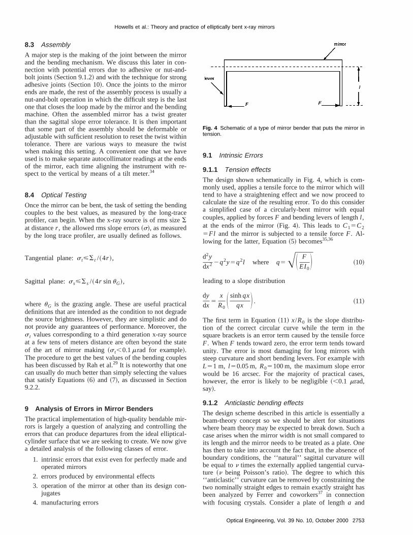
The design shown schematically in Fig. 4, which is comonly used, applies a tensile force to the mirror which wtend to have a straightening effect and we now proceecalculate the size of the resulting error. To do this consia simplified case of a circularly-bent mirror with equcouples, applied by forcesF and bending levers of lengthl ,at the ends of the mirror~Fig. 4!. This leads toC15C2
5Fl and the mirror is subjected to a tensile forceF. Al-lowing for the latter, Equation~5! becomes35,36
d2y
dx2 2q2y5q2l where q5AS F
EI0D ~10!
leading to a slope distribution
dy
dx5
x
R0S sinhqx
qx D . ~11!
The first term in Equation~11! x/R0 is the slope distribu-tion of the correct circular curve while the term in thsquare brackets is an error term caused by the tensile fF. WhenF tends toward zero, the error term tends towaunity. The error is most damaging for long mirrors wisteep curvature and short bending levers. For exampleL51 m, l 50.05 m, R05100 m, the maximum slope errowould be 16 arcsec. For the majority of practical cashowever, the error is likely to be negligible~,0.1 mrad,say!.
9.1.2 Anticlastic bending effects
The design scheme described in this article is essentiabeam-theory concept so we should be alert for situatiwhere beam theory may be expected to break down. Sucase arises when the mirror width is not small comparedits length and the mirror needs to be treated as a plate.has then to take into account the fact that, in the absencboundary conditions, the ‘‘natural’’ sagittal curvature wbe equal ton times the externally applied tangential curvture ~n being Poisson’s ratio!. The degree to which this‘‘anticlastic’’ curvature can be removed by constraining ttwo nominally straight edges to remain exactly straight hbeen analyzed by Ferrer and coworkers37 in connectionwith focusing crystals. Consider a plate of lengtha and
Fig. 4 Schematic of a type of mirror bender that puts the mirror intension.
2753Optical Engineering, Vol. 39 No. 10, October 2000
ite
-
het thomng
arthehahee
lus
sti-
uce
teualy
ched.no
thed.
lue
toe
ng-eslopeekinghtthein-edch
nd.ectcesyerr-ndn-but
ingic-
ichit-
ns
Howells et al.: Theory and practice of elliptically bent x-ray mirrors
width b bent into a circular cylinder by equal and opposcouples applied to the edgesx50 and x5a, which areassumed to be clamped straight. Thex andy axes are de-fined so that the edges of the plate arex50, x5a and y56b/2. It can then be shown38,39using the standard methods of plate theory,40 that the closed-form solution forw~the out-of-plane displacement! is as follows.
w5 (m51
` S 4a2
Rp3
1
m3 1Am coshmpy
a
1Bm
mpy
asinh
mpy
a D sinmpx
a, ~12!
whereR is the nominal bending radius,m51, 3, 5, . . . and
Am5Cm@sinham~11n!2amcosham~12n!#
Bm5Cm sinham~12n!
Cm54a2n
Rp3
1
m3
1
sinham cosham~31n!~12n!2am~12n!2
and am5mpb
2a.
The first term of this solution is the Fourier series of tintended cylindrical shape and the other terms represenerrors due to anticlastic bending. Such errors can becimportant for mirrors with large widths and/or large graziangles.
Another type of anticlastic-bending effect may appewhen a glass or silicon mirror substrate is glued tometal plate that is used for attaching the bending mecnism. An important factor to consider in this case is tfractional shrinkage«G of the glue. First we consider theffect of shrinkage of the glue layerin its own plane. Sup-pose we are joining two plates of thickness, elastic moduand Poisson’s ratioh1 , E1 , n1 andh2 , E2 andn2 , respec-tively. Suppose further that the glue layer behaves elacally and has thicknesshG(!h1 ,h2) and modulusEG . Itcan then be shown that the stress due to shrinkage inda spherical radiusRG given by
RG5E1h1
2
6~12n1!«GEGhG
114en16en214en31e2n4
12en2 ,
~13!
where n5h2 /h1 and e5@E1 /(12n1)#/@E2 /(12n2)#. Inthe special case thatn→0, which represents a single plawith a thin coating, the second fraction on the right is eqto unity and Equation ~13! reduces to the Stoneequation.41 Now, in practical cases~glue thickness about 50to 150mm!, the cross section of the glue layer will be musmaller than that of the two plates that are being joinTherefore the shrinkage forces due to the glue layer arelikely to produce a large distortion. Nevertheless, atmicroradian level, this is still something to keep in minUp to now there is no anticlastic effect due to the glue.
2754 Optical Engineering, Vol. 39 No. 10, October 2000
ee
-
s
t
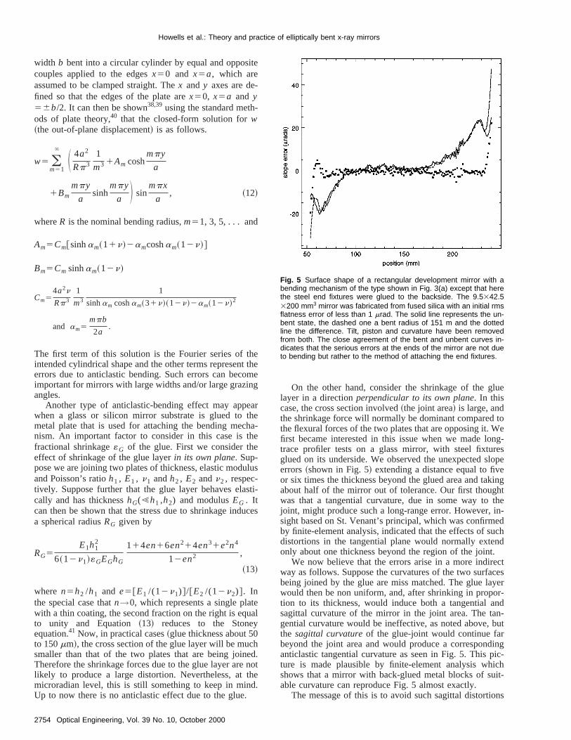
On the other hand, consider the shrinkage of the glayer in a directionperpendicular to its own plane. In thiscase, the cross section involved~the joint area! is large, andthe shrinkage force will normally be dominant comparedthe flexural forces of the two plates that are opposing it. Wfirst became interested in this issue when we made lotrace profiler tests on a glass mirror, with steel fixturglued on its underside. We observed the unexpected serrors~shown in Fig. 5! extending a distance equal to fivor six times the thickness beyond the glued area and taabout half of the mirror out of tolerance. Our first thougwas that a tangential curvature, due in some way tojoint, might produce such a long-range error. However,sight based on St. Venant’s principal, which was confirmby finite-element analysis, indicated that the effects of sudistortions in the tangential plane would normally exteonly about one thickness beyond the region of the joint
We now believe that the errors arise in a more indirway as follows. Suppose the curvatures of the two surfabeing joined by the glue are miss matched. The glue lawould then be non uniform, and, after shrinking in propotion to its thickness, would induce both a tangential asagittal curvature of the mirror in the joint area. The tagential curvature would be ineffective, as noted above,the sagittal curvatureof the glue-joint would continue farbeyond the joint area and would produce a correspondanticlastic tangential curvature as seen in Fig. 5. This pture is made plausible by finite-element analysis whshows that a mirror with back-glued metal blocks of suable curvature can reproduce Fig. 5 almost exactly.
The message of this is to avoid such sagittal distortio
Fig. 5 Surface shape of a rectangular development mirror with abending mechanism of the type shown in Fig. 3(a) except that herethe steel end fixtures were glued to the backside. The 9.5342.53200 mm3 mirror was fabricated from fused silica with an initial rmsflatness error of less than 1 mrad. The solid line represents the un-bent state, the dashed one a bent radius of 151 m and the dottedline the difference. Tilt, piston and curvature have been removedfrom both. The close agreement of the bent and unbent curves in-dicates that the serious errors at the ends of the mirror are not dueto bending but rather to the method of attaching the end fixtures.

or
harlynanm.a
kes
enlus-ex
argr
rain
dt
ofofen
uesedctinbeeth
on
ra-gesn-
sedhear
up-ar
x--is
edrical
in-
enderi-netion.icalrmisftheby
-ingndnds.
of
Howells et al.: Theory and practice of elliptically bent x-ray mirrors
at the ends of the mirror. This is equally important fbolted or glued joints to the back~or front! of the mirror. Itappears that VUV and soft x-ray mirrors with their higcurvature and corresponding low thickness are particulvulnerable to this type of error. If the mirror is thicker thaabout 0.5 cm, then the fixtures can be glued to the endin our experience this is one way to eliminate the probleFor hard x-ray mirrors, typically having lengths up tometer and radii of at least a kilometer, one normally mathe thickness much greater~5 to 10 cm! to resist bendingunder gravity and in these cases the distortions due toattachments are much less of a problem. We give an iltration of bending a beam of this general shape in the nsection.
9.1.3 Line and strip loading of the mirror surface byclamps
In several traditional bender designs, the end couplesapplied to the mirror by four rods in a four-point-bendinconfiguration.42 This delivers a line loading to the mirrosurface. The surface slope at distancex along a line per-pendicular to the line load can be calculated in plane stif the mirror is idealized as a 2-D elastic half plane.43
slope5~12n2!2P
pE
1
x~ line load!, ~14!
whereP is the load per unit length. If the load is applieover a finite area of width 2a, roughly representing a flaclamp, the effect can be obtained by integration43 of Equa-tion ~14!.
slope52~12n2!p
pEln S x1a
x2aD ~strip load!, ~15!
where p is the load per unit area. We compared boththese equations to finite-element analysis of mirrorsthickness 1 cm with realistic bending loads. The agreemwas good and, furthermore, the slope errors fell to valmuch less than a microradian within 1 cm of the loadarea. This suggests that bender designs using clamps aperpendicular to the mirror surface can, in principle,effective. As an illustration of these types of calculation wshow both the measured and calculated 2-D stresses infour-point-bender geometry as given in a classical textphotoelasticity44 ~Fig. 6!.
9.2 Errors Produced by Environmental Effects
The environmental influences that impact synchrotrondiation optics are mainly the vacuum, the thermal chandue to illumination by the beam and gravity. Here we cosider only the last two.
9.2.1 Temperature
If the mirror expands more than the base then one canfrom Figs. 3~a! or 3~b! that the result will be unintendeend couples tending to make the mirror more convex. Tslope errors at the ends produced by such couples3aeiL2/2EIl 2 radians/°C whereE, I , L ande, i , l are themodulus, section moment and length of the mirror and sport legs, respectively. To ensure that these slope errors
d
d
t
e
t
g
e
e
e
e
negligibly small, we have to make the legs sufficiently fleible within the limitation that the loading should not approach the critical force for buckling, which in this casep2ei/ l 2. This is generally easy to do.
9.2.2 Gravity
When a mirror of uniform cross section, simply supportat its ends, sags under gravity, it assumes a symmetshape of the general typey5ax21bx4, which represents amixture of defocus and spherical aberration. Under thefluence of gravity alonea and b take the valuesa0
5mL2/16EI and b052m/24EI, wherem is the weightper unit length. This shows that the slope error at eitherdue to defocus is three times larger than that due to sphcal aberration and in the opposite direction so that theend slope error is twice that due to the spherical aberratFor convenience we adopt the magnitude of the spheraberration end slope as a reference ‘‘unit.’’ For a unifomirror under gravity alone the size of the unit2mL3/48EI. For ‘‘rigid’’ mirrors one can remove much othe distortion by choosing the best spacing betweensupport points. An analysis of this choice has been givenHowells and Lunt,20 who show that the minimum gravitational peak-to-valley slope error is achieved with a spacof L/), which gives a factor 16.4 improvement in the eslope error compared to having the supports at the eOther approaches to eliminating the unwanted effects
Fig. 6 Theory-of-elasticity calculation in plane stress (a) and photo-elastic measurement (b) of the stress pattern due to four-point bend-ing of a uniform beam.44 Note that the pattern of purely longitudinalstresses that one expects for a circularly bent beam is not estab-lished until about one thickness away from the applied point loadsthat produce a locally nonideal stress pattern.
2755Optical Engineering, Vol. 39 No. 10, October 2000
elsby
ndea-ror.ingve.
a
nuan
b-dre-o-asis
dheg-
eri-thetotheera-
n-iment opere a
edr
he
tralof
tionseranf
i-
Thithere-iouroral-
x-ceselifi-
are
theofsu-
u-theeti-a-ral
nture
ingthefinal
oiatedatisthe
Howells et al.: Theory and practice of elliptically bent x-ray mirrors
gravity are an increase inI /m ~for example, by an increasof the depth!, the use of high-specific-strength materiasuch as beryllium or silicon carbide or active correctiona series of springs.14
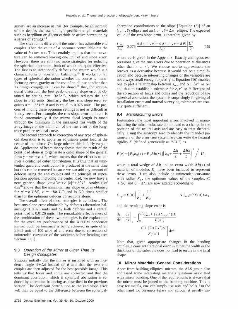
The situation is different if the mirror has adjustable ecouples. Then the value ofa becomes controllable but thvalue ofb does not. This certainly implies that the curvture can be removed leaving one unit of end slope erHowever, there are still two more strategies for reducthe spherical aberration, both of which are quite effectiThe first is to intentionally defocus the system which isclassical form of aberration balancing.45 It works for alltypes of spherical aberration whether the source is mafacturing error, gravity or the use of an ellipse at other thits design conjugates. It can be shown46 that, for gravita-tional distortion, the best peak-to-valley slope error is otained by settinga523bL2/8, which reduces the enslope to 0.25 units. Similarly the best rms slope errorquiresa523bL2/10 and is equal to 0.076 units. The prcess of finding these optimum settings is not as difficultit may seem. For example, the rms-slope-error optimumfound automatically if the mirror focal length is tunethrough the minimum in the measured rms width of tx-ray image or the minimum of the rms error of the lontrace profiler residual curve.
The second approach to correction of any type of sphcal aberration is to apply an adjustable point load atcenter of the mirror. On large mirrors this is fairly easydo. Application of beam theory shows that the result ofpoint load alone is to generate a cubic shape of the genform y5ux21vuxu3, which means that the effect is to deliver a controlled cubic contribution. It is true that an unitended quadratic contribution is produced at the same tbut this can be removed because we can add any amoudefocus using the end couples and the principle of suposition applies. Including the center load, we now havnew generic shapey5a8x21c8uxu31b8x4. Analysis ofthis46 shows that the minimum rms slope error is obtainfor a85b8L2/5, c8528b8L/9 and is 6.0 times smallethan for the optimum defocus corrections alone.
The overall effect of these strategies is as follows. Tbest rms slope error obtainable by defocus~aberration bal-ancing! is 0.076 units and by both defocus and a cenpoint load is 0.0126 units. The remarkable effectivenessthe combination of these two strategies is the explanafor the excellent performance of the XPEEM condenmirror. Such performance is being achieved in spite ofinitial unit of 100 mrad of end error due to correction ounintended curvature of the substrate before bending~seeSection 11.1!.
9.3 Operation of the Mirror at Other Than ItsDesign Conjugates
Suppose initially that the mirror is installed with an incdence angleu1Du instead of u and that the two endcouples are then adjusted for the best possible image.tells us that focus and coma are corrected and thatdominant aberration, which is spherical aberration isduced by aberration balancing as described in the prevsection. The dominant contribution to the end slope erwill then be equal to the difference between the spheric
2756 Optical Engineering, Vol. 39 No. 10, October 2000
-
l
f-
s
s
aberration contributions to the slope@Equation~3!# of an(r ,r 8,u) ellipse and an (r ,r 8,u1Du) ellipse. The expectedvalue of the rms slope error is therefore given by
srms
Du50.076Fa4~r , r 8, u!2a4~r , r 8, u1Du!
Du G L3
2, ~16!
wherea4 is given in the Appendix. Exactly analogous epressions give the rms errors due to operation at distanother thanr or r 8. We choose not to approximate thbracket as a derivative because it would not be a simpcation and because interesting changes of the variablesnot always small enough to justify it. Equation~16! enablesone to plot a relationship betweensrms andDr , Dr 8 or Duand thus to establish a tolerance forr , r 8 or u. Because ofthe correction of focus and coma and the reduction ofspherical aberration, the system is surprisingly forgivinginstallation errors and normal surveying tolerances are ually quite sufficient.
9.4 Manufacturing Errors
Fortunately, the most important errors involved in manfacturing the mirror substrate do not lead to a change inposition of the neutral axis and are easy to treat theorcally. Using the subscript zero to identify the intended prameters of the error-free system, we can write the flexurigidity F ~defined generically as ‘‘EI ’’ ! as
F~x!5@E0b0~x!1E1Db~x!#S h01Dh
21
Dhx
L D 3Y 12,
where a total wedge ofDh and an extra widthDb(x) ofmaterial of modulusE1 have been included to represethese errors. If we also include an unintended curvatwith radius Re , the optimum values of the couples,C1DC andC2DC are now altered according to
Copt5F~0!S 1
R01
1
ReD DCopt53F~0!La3
and the resulting slope error is
dy
dx2
dy
dx U0
5E0
xFCopt1 ~2DCoptx8!/L
F~x8!
2C1 ~2DCx8!/L
F0~x8! G dx8.
Note that, given appropriate changes in the bendcouples, a constant fractional error in either the width orthickness of the substrate does not lead to errors in theshape.
10 Mirror Materials: General Considerations
Apart from building elliptical mirrors, the ALS group alsaddressed some interesting materials questions assocwith mirror bending. One of the requirements is always ththe mirror must be joined to the bending machine. Thiseasy for metals, one can simply use nuts and bolts. Onother hand for ceramics~glass and silicon! it usually im-
ionthee-tontos
their-
tro-s o
aysaretic
nlyat aGP
in-of
geith
ar-dia
or-seehashe
pac
s intro
the
ou
toun-l ofetaibeles
sumers
e
ni-f th
ir-inilarr
oft-ro-eo-
ofility,ents
ww
tac-leherors als.the
alherw
de-tion14
the
as
Howells et al.: Theory and practice of elliptically bent x-ray mirrors
plies the use of adhesive or solder, which raises questof shrinkage and distortion discussed earlier. To buildm-XPS mirrors~see Table 1!, it was necessary to bend onmirror to 4.5 m radius. This is difficult for ceramics because, due to stress considerations, the thickness hasreduced to around a millimeter, which gives insufficierigidity for high-quality polishing. For metals, it is easy tfind materials with a high stress capability, which allowthe substrate to be thicker and easier to polish. On the ohand, metals do not offer a path to multilayer-coated mrors and there are obviously risks in subjecting an elecless-nickel coating, which may have significant stresseits own, to high bending stress.
We approached these technical challenges in two wFirst we developed the technique of superpolishing bstainless steel.47 The material used was a martensiprecipitation-hardening stainless steel~type 17-4 PH!,which has manufacturing properties similar to commoused alloys such as type 304, and which, upon agingmoderate temperature, acquires a yield strength of 1.3and excellent dimensional stability~changes48 ,0.05 ppm/year!. A more detailed study of the materials issuesvolved in the stability, polishability and other propertiesthis alloy are given by Howells and Casstevens.47 The fin-ish achieved by Dallas Optical Systems~Rockwell, Texas,1996! on a total of 13 mirrors to date has been in the ran2 to 3 Å rms as measured by the ALS optical profiler wspatial frequency range 0.3 to 100 mm21. We believe thatthis ability to superpolish stainless steel could have freaching consequences for the design of synchrotron ration optics generally.
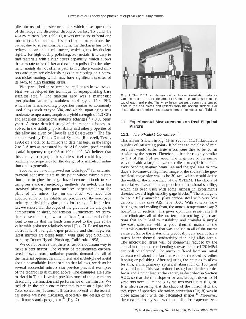
Second, we have improved our technique49 for ceramic-to-metal adhesive joints to the point where mirror disttions due to glue shrinkage have become difficult tousing our standard metrology methods. As noted, thisinvolved placing the joint surfaces perpendicular to tplane of the mirror~i.e., on the ends!. We have alsoadopted some of the established practices of the aerosindustry in designing glue joints for strength.50 In particu-lar, we ensure that the edges of the glue layer are alwaycompression or shear, not tension. Furthermore, we induce a weak link~known as a ‘‘foot’’! at one end of thejoint to ensure that the loads transferred to the glue atvulnerable point are relatively small~Fig. 7!. Based on con-siderations of strength, vapor pressure and shrinkage,latest mirrors are being built49 with glue type 9309.3NAmade by Dexter-Hysol~Pittsburg, California, 1998!.
We do not believe that there is just one optimum waymake a bent mirror. The variety of requirements encotered in synchrotron radiation practice demand that althe material options, ceramic, metal and nickel-plated mshould be available. In the section that follows, we descrseveral successful mirrors that provide practical exampof the techniques discussed above. The examples aremarized in Table 1, which provides most of the parametdescribing the function and performance of the mirrors. Winclude in the table one mirror that is not an ellipse~the7.3.3 condenser! because it illustrates several of the techcal issues we have discussed, especially the design oend fixtures and epoxy joints49 ~Fig. 7!.
s
be
r
f
.
a
-
e
-
r
l
-
e
11 Experimental Measurements on Real EllipticalMirrors
11.1 The XPEEM Condenser 51
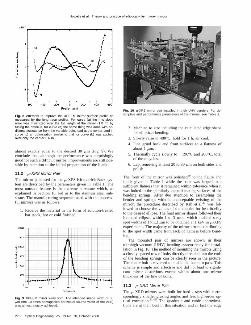
This mirror ~shown in Fig. 15 in Section 11.3! illustrates anumber of interesting points. It belongs to the class of mrors that would suffer large errors were they to be puttension by the bender. Therefore, a bender roughly simto that of Fig. 3~b! was used. The large size of the mirrowas to enable a large horizontal collection angle for a sx-ray bending magnet beam line and the goal was to pduce a 10-times-demagnified image of the source. The gmetrical image size was to be 30mm, which would definethe width of the image field of the XPEEM. The choicematerial was based on an approach to dimensional stabwhich has been used with some success in experimdirected toward high-stability gage-blocks.48 The strategy isto use a fully annealed, plain carbon steel with very locarbon, in this case AISI type 1006. With suitably sloheating to, and cooling from, the anneal temperature~say 2hours/cm of section!, this gives optimum stress relief. Ialso eliminates all of the martensite-tempering-type retions that could lead to instability, and provides a simplow-cost substrate with a good thermal match to telectroless-nickel layer that was applied to all of the mirsurfaces. Since the material is practically pure iron, it hamuch better thermal conductivity than high-alloy steeThe microyield stress will be somewhat reduced byanneal but the moderate bending stresses required~20 MPa!can still be tolerated. The mirror suffered from an initicurvature of about 0.5 km that was not removed by eitlapping or polishing. After adjusting the couples to allofor this, a marginal-ray spherical aberration of 100mradwas produced. This was reduced using both deliberatefocus and a point load at the center, as described in Sec9.2.2, so that the rms slope error was brought down tomrad rms over 1.1 m and 3.0mrad rms over 0.6 m~Fig. 8!.It is also reassuring that the shape of the mirror aftertwo types of spherical-aberration correction~Fig. 8! was inclose agreement with the calculated shapes.46 Moreover,the measured x-ray spot width at full mirror aperture w
Fig. 7 The 7.3.3. condenser mirror before installation into itsvacuum tank. The ‘‘foot’’ described in Section 10 can be seen at thetop of each end plate. The x-ray beam passes through the curvedslots in the end plates and reflects from the bottom surface. Fordescriptive and performance parameters of the mirror, see Table 1.
2757Optical Engineering, Vol. 39 No. 10, October 2000
glys-
Theas
ubes
ed
pe
of
ait
thethe
lityeir
gd-
ir-gdsre.Thisifi-r
-op--ge
Howells et al.: Theory and practice of elliptically bent x-ray mirrors
almost exactly equal to the desired 30mm ~Fig. 9!. Weconclude that, although the performance was surprisingood for such a difficult mirror, improvements are still posible by attention to the initial preparation of the blank.
11.2 m-XPS Mirror Pair
The mirror pair used for them-XPS Kirkpatrick-Baez sys-tem are described by the parameters given in Table 1.most unusual feature is the extreme curvature which,explained in Section 10, led us to the stainless steel sstrate. The manufacturing sequence used with the succful mirrors was as follows.
1. Receive the material in the form of solution-treatbar stock, hot or cold finished.
Fig. 8 Attempts to improve the XPEEM mirror surface profile asmeasured by the long-trace profiler. For curve (a) the rms slopeerror was minimized over the full length of the mirror (1.0 m) bytuning the defocus, for curve (b) the same thing was done with ad-ditional assistance from the variable point load at the center, and incurve (c) an optimization similar to that for curve (b) was appliedover only the center 0.6 m.
Fig. 9 XPEEM mirror x-ray spot. The intended image width of 30mm (the 10-times-demagnified horizontal source width of the ALS)was almost exactly achieved.
2758 Optical Engineering, Vol. 39 No. 10, October 2000
-s-
2. Machine to size including the calculated edge shafor elliptical bending.
3. Slowly raise to 480°C, hold for 1 h, air cool.
4. Fine grind back and front surfaces to a flatnessabout 1mm.
5. Thermally cycle slowly to2196°C and 200°C, totalof three cycles.
6. Lap, removing at least 20 to 30mm on both sides andpolish.
The front of the mirror was polished49 to the figure andfinish given in Table 1 while the back was lapped tosufficient flatness that it remained within tolerance whenwas bolted to the~similarly lapped! mating surfaces of thebending springs. After due attention to assemblingbender and springs without unacceptable twisting ofmirror, the procedure described by Rah et al.29 was fol-lowed to choose the values of the couples for best fideto the desired ellipse. The final mirror shapes followed thintended ellipses within 1 to 3mrad, which enabled x-rayspot widths of 131.2mm to be obtained at 1 keV inm-XPSexperiments. The majority of the mirror errors contributinto the spot width came from lack of flatness before bening.
The mounted pair of mirrors are shown in theultrahigh-vacuum~UHV! bending system ready for installation in Fig. 10. The method of mounting the mirrors usina closely spaced row of bolts directly threaded into the enof the bending springs can be clearly seen in the pictuThe center bolt is reversed to enable the beam to pass.scheme is simple and effective and did not lead to signcant mirror distortions except within about one mirrothickness of the line of bolts.
11.3 m-XRD Mirror Pair
The m-XRD mirrors were built for hard x rays with correspondingly smaller grazing angles and less high-ordertical correction.21–23 The quadratic and cubic approximations are at their best in this situation and in fact the ed
Fig. 10 m-XPS mirror pair installed in their UHV benders. For de-scriptive and performance parameters of the mirrors, see Table 1.
heouee-
. 5.tillcesirroth1.r o
- tion
iones
entis-
towto
m-the
e-
fe
rg-
Howells et al.: Theory and practice of elliptically bent x-ray mirrors
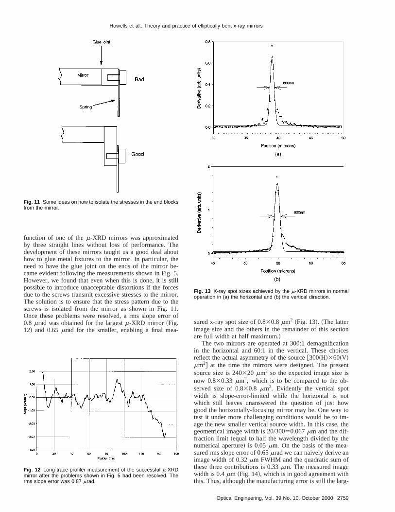
function of one of them-XRD mirrors was approximatedby three straight lines without loss of performance. Tdevelopment of these mirrors taught us a good deal abhow to glue metal fixtures to the mirror. In particular, thneed to have the glue joint on the ends of the mirror bcame evident following the measurements shown in FigHowever, we found that even when this is done, it is spossible to introduce unacceptable distortions if the fordue to the screws transmit excessive stresses to the mThe solution is to ensure that the stress pattern due toscrews is isolated from the mirror as shown in Fig. 1Once these problems were resolved, a rms slope erro0.8 mrad was obtained for the largestm-XRD mirror ~Fig.12! and 0.65mrad for the smaller, enabling a final mea
Fig. 11 Some ideas on how to isolate the stresses in the end blocksfrom the mirror.
Fig. 12 Long-trace-profiler measurement of the successful m-XRDmirror after the problems shown in Fig. 5 had been resolved. Therms slope error was 0.87 mrad.
t
r.e
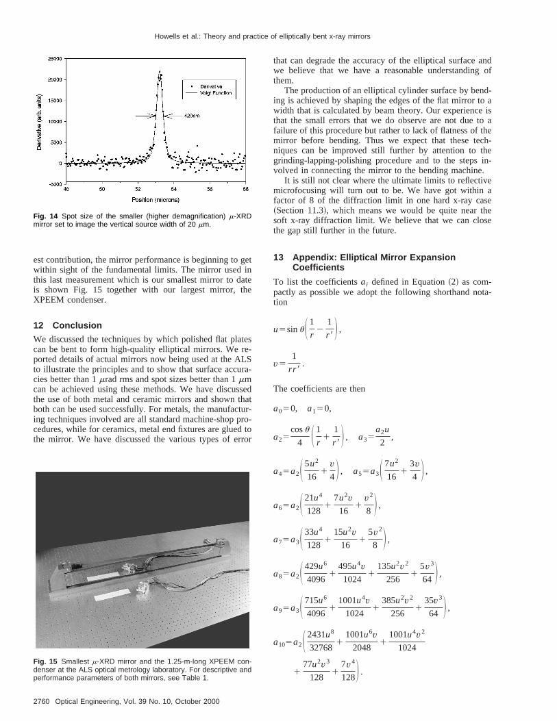
fsured x-ray spot size of 0.830.8 mm2 ~Fig. 13!. ~The latterimage size and the others in the remainder of this secare full width at half maximum.!
The two mirrors are operated at 300:1 demagnificatin the horizontal and 60:1 in the vertical. These choicreflect the actual asymmetry of the source@300~H!360~V!mm2# at the time the mirrors were designed. The pressource size is 240320 mm2 so the expected image sizenow 0.830.33 mm2, which is to be compared to the observed size of 0.830.8 mm2. Evidently the vertical spotwidth is slope-error-limited while the horizontal is nowhich still leaves unanswered the question of just hgood the horizontally-focusing mirror may be. One waytest it under more challenging conditions would be to iage the new smaller vertical source width. In this case,geometrical image width is 20/30050.067mm and the dif-fraction limit ~equal to half the wavelength divided by thnumerical aperture! is 0.05mm. On the basis of the measured rms slope error of 0.65mrad we can naively derive animage width of 0.32mm FWHM and the quadratic sum othese three contributions is 0.33mm. The measured imagwidth is 0.4mm ~Fig. 14!, which is in good agreement withthis. Thus, although the manufacturing error is still the la
Fig. 13 X-ray spot sizes achieved by the m-XRD mirrors in normaloperation in (a) the horizontal and (b) the vertical direction.
2759Optical Engineering, Vol. 39 No. 10, October 2000
getinatehe
tese-LSra-
ssethacturprod torror
andof
d-o a
isto ahech-hein-.eaeee
ta-
Howells et al.: Theory and practice of elliptically bent x-ray mirrors
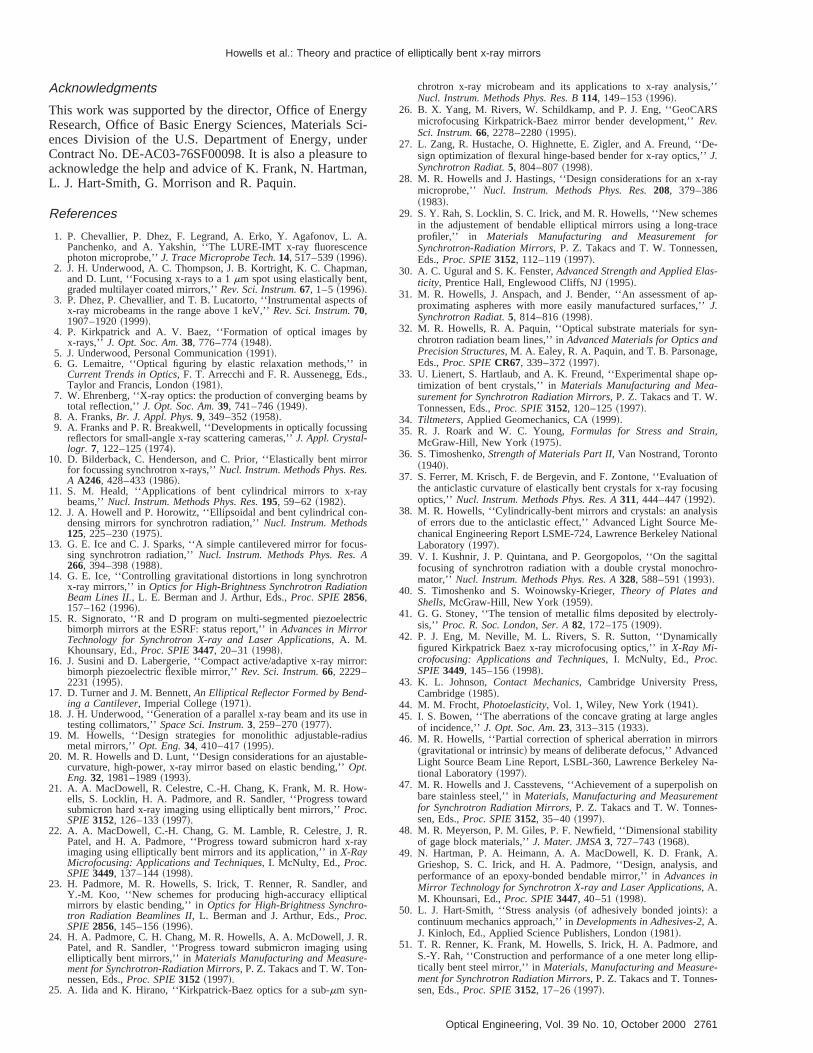
est contribution, the mirror performance is beginning towithin sight of the fundamental limits. The mirror usedthis last measurement which is our smallest mirror to dis shown Fig. 15 together with our largest mirror, tXPEEM condenser.
12 Conclusion
We discussed the techniques by which polished flat placan be bent to form high-quality elliptical mirrors. We rported details of actual mirrors now being used at the Ato illustrate the principles and to show that surface accucies better than 1mrad rms and spot sizes better than 1mmcan be achieved using these methods. We have discuthe use of both metal and ceramic mirrors and shownboth can be used successfully. For metals, the manufaing techniques involved are all standard machine-shopcedures, while for ceramics, metal end fixtures are gluethe mirror. We have discussed the various types of e
Fig. 14 Spot size of the smaller (higher demagnification) m-XRDmirror set to image the vertical source width of 20 mm.
Fig. 15 Smallest m-XRD mirror and the 1.25-m-long XPEEM con-denser at the ALS optical metrology laboratory. For descriptive andperformance parameters of both mirrors, see Table 1.
2760 Optical Engineering, Vol. 39 No. 10, October 2000
dt--
that can degrade the accuracy of the elliptical surfacewe believe that we have a reasonable understandingthem.
The production of an elliptical cylinder surface by bening is achieved by shaping the edges of the flat mirror twidth that is calculated by beam theory. Our experiencethat the small errors that we do observe are not duefailure of this procedure but rather to lack of flatness of tmirror before bending. Thus we expect that these teniques can be improved still further by attention to tgrinding-lapping-polishing procedure and to the stepsvolved in connecting the mirror to the bending machine
It is still not clear where the ultimate limits to reflectivmicrofocusing will turn out to be. We have got withinfactor of 8 of the diffraction limit in one hard x-ray cas~Section 11.3!, which means we would be quite near thsoft x-ray diffraction limit. We believe that we can closthe gap still further in the future.
13 Appendix: Elliptical Mirror ExpansionCoefficients
To list the coefficientsai defined in Equation~2! as com-pactly as possible we adopt the following shorthand notion
u5sinuS 1
r2
1
r 8D ,
v51
rr 8.
The coefficients are then
a050, a150,
a25cosu
4 S 1
r1
1
r 8D , a35a2u
2,
a45a2S 5u2
161
v4D , a55a3S 7u2
161
3v4 D ,
a65a2S 21u4
1281
7u2v16
1v2
8 D ,
a75a3S 33u4
1281
15u2v16
15v2
8 D ,
a85a2S 429u6
40961
495u4v1024
1135u2v2
2561
5v3
64 D ,
a95a3S 715u6
40961
1001u4v1024
1385u2v2
2561
35v3
64 D ,
a105a2S 2431u8
327681
1001u6v2048
11001u4v2
1024
177u2v3
1281
7v4
128D .
gyScierto
an,
A.ce
an,,
s of
y
in.,
by
ing
rors.
y
-
us-A
nn
tric
ror:
-
e in
us
le-
-ard
R.-ray
ndal-
R.ing
--
s,’’
S
e-
ray
escer
n,
-
ap-’’
n-
e,
op-
ofing
ise-nal
ittalro-
ly-
y
,
gles
rsda-
ont-
ty
.nd
ndlip---
Howells et al.: Theory and practice of elliptically bent x-ray mirrors
Acknowledgments
This work was supported by the director, Office of EnerResearch, Office of Basic Energy Sciences, Materialsences Division of the U.S. Department of Energy, undContract No. DE-AC03-76SF00098. It is also a pleasureacknowledge the help and advice of K. Frank, N. HartmL. J. Hart-Smith, G. Morrison and R. Paquin.
References
1. P. Chevallier, P. Dhez, F. Legrand, A. Erko, Y. Agafonov, L.Panchenko, and A. Yakshin, ‘‘The LURE-IMT x-ray fluorescenphoton microprobe,’’J. Trace Microprobe Tech.14, 517–539~1996!.
2. J. H. Underwood, A. C. Thompson, J. B. Kortright, K. C. Chapmand D. Lunt, ‘‘Focusing x-rays to a 1mm spot using elastically bentgraded multilayer coated mirrors,’’Rev. Sci. Instrum.67, 1–5~1996!.
3. P. Dhez, P. Chevallier, and T. B. Lucatorto, ‘‘Instrumental aspectx-ray microbeams in the range above 1 keV,’’Rev. Sci. Instrum.70,1907–1920~1999!.
4. P. Kirkpatrick and A. V. Baez, ‘‘Formation of optical images bx-rays,’’ J. Opt. Soc. Am.38, 776–774~1948!.
5. J. Underwood, Personal Communication~1991!.6. G. Lemaitre, ‘‘Optical figuring by elastic relaxation methods,’’
Current Trends in Optics, F. T. Arrecchi and F. R. Aussenegg, EdsTaylor and Francis, London~1981!.
7. W. Ehrenberg, ‘‘X-ray optics: the production of converging beamstotal reflection,’’J. Opt. Soc. Am.39, 741–746~1949!.
8. A. Franks,Br. J. Appl. Phys.9, 349–352~1958!.9. A. Franks and P. R. Breakwell, ‘‘Developments in optically focuss
reflectors for small-angle x-ray scattering cameras,’’J. Appl. Crystal-logr. 7, 122–125~1974!.
10. D. Bilderback, C. Henderson, and C. Prior, ‘‘Elastically bent mirfor focussing synchrotron x-rays,’’Nucl. Instrum. Methods Phys. ReA A246, 428–433~1986!.
11. S. M. Heald, ‘‘Applications of bent cylindrical mirrors to x-rabeams,’’Nucl. Instrum. Methods Phys. Res.195, 59–62~1982!.
12. J. A. Howell and P. Horowitz, ‘‘Ellipsoidal and bent cylindrical condensing mirrors for synchrotron radiation,’’Nucl. Instrum. Methods125, 225–230~1975!.
13. G. E. Ice and C. J. Sparks, ‘‘A simple cantilevered mirror for focsing synchrotron radiation,’’Nucl. Instrum. Methods Phys. Res.266, 394–398~1988!.
14. G. E. Ice, ‘‘Controlling gravitational distortions in long synchrotrox-ray mirrors,’’ in Optics for High-Brightness Synchrotron RadiatioBeam Lines II., L. E. Berman and J. Arthur, Eds.,Proc. SPIE2856,157–162~1996!.
15. R. Signorato, ‘‘R and D program on multi-segmented piezoelecbimorph mirrors at the ESRF: status report,’’ inAdvances in MirrorTechnology for Synchrotron X-ray and Laser Applications, A. M.Khounsary, Ed.,Proc. SPIE3447, 20–31~1998!.
16. J. Susini and D. Labergerie, ‘‘Compact active/adaptive x-ray mirbimorph piezoelectric flexible mirror,’’Rev. Sci. Instrum.66, 2229–2231 ~1995!.
17. D. Turner and J. M. Bennett,An Elliptical Reflector Formed by Bending a Cantilever, Imperial College~1971!.
18. J. H. Underwood, ‘‘Generation of a parallel x-ray beam and its ustesting collimators,’’Space Sci. Instrum.3, 259–270~1977!.
19. M. Howells, ‘‘Design strategies for monolithic adjustable-radimetal mirrors,’’Opt. Eng.34, 410–417~1995!.
20. M. R. Howells and D. Lunt, ‘‘Design considerations for an ajustabcurvature, high-power, x-ray mirror based on elastic bending,’’Opt.Eng.32, 1981–1989~1993!.
21. A. A. MacDowell, R. Celestre, C.-H. Chang, K. Frank, M. R. Howells, S. Locklin, H. A. Padmore, and R. Sandler, ‘‘Progress towsubmicron hard x-ray imaging using elliptically bent mirrors,’’Proc.SPIE3152, 126–133~1997!.
22. A. A. MacDowell, C.-H. Chang, G. M. Lamble, R. Celestre, J.Patel, and H. A. Padmore, ‘‘Progress toward submicron hard ximaging using elliptically bent mirrors and its application,’’ inX-RayMicrofocusing: Applications and Techniques, I. McNulty, Ed., Proc.SPIE3449, 137–144~1998!.
23. H. Padmore, M. R. Howells, S. Irick, T. Renner, R. Sandler, aY.-M. Koo, ‘‘New schemes for producing high-accuracy ellipticmirrors by elastic bending,’’ inOptics for High-Brightness Synchrotron Radiation Beamlines II, L. Berman and J. Arthur, Eds.,Proc.SPIE2856, 145–156~1996!.
24. H. A. Padmore, C. H. Chang, M. R. Howells, A. A. McDowell, J.Patel, and R. Sandler, ‘‘Progress toward submicron imaging uselliptically bent mirrors,’’ in Materials Manufacturing and Measurement for Synchrotron-Radiation Mirrors, P. Z. Takacs and T. W. Tonnessen, Eds.,Proc. SPIE3152 ~1997!.
25. A. Iida and K. Hirano, ‘‘Kirkpatrick-Baez optics for a sub-mm syn-
-
chrotron x-ray microbeam and its applications to x-ray analysiNucl. Instrum. Methods Phys. Res. B114, 149–153~1996!.
26. B. X. Yang, M. Rivers, W. Schildkamp, and P. J. Eng, ‘‘GeoCARmicrofocusing Kirkpatrick-Baez mirror bender development,’’Rev.Sci. Instrum.66, 2278–2280~1995!.
27. L. Zang, R. Hustache, O. Highnette, E. Zigler, and A. Freund, ‘‘Dsign optimization of flexural hinge-based bender for x-ray optics,’’J.Synchrotron Radiat.5, 804–807~1998!.
28. M. R. Howells and J. Hastings, ‘‘Design considerations for an x-microprobe,’’ Nucl. Instrum. Methods Phys. Res.208, 379–386~1983!.
29. S. Y. Rah, S. Locklin, S. C. Irick, and M. R. Howells, ‘‘New schemin the adjustement of bendable elliptical mirrors using a long-traprofiler,’’ in Materials Manufacturing and Measurement foSynchrotron-Radiation Mirrors, P. Z. Takacs and T. W. TonnesseEds.,Proc. SPIE3152, 112–119~1997!.
30. A. C. Ugural and S. K. Fenster,Advanced Strength and Applied Elasticity, Prentice Hall, Englewood Cliffs, NJ~1995!.
31. M. R. Howells, J. Anspach, and J. Bender, ‘‘An assessment ofproximating aspheres with more easily manufactured surfaces,J.Synchrotron Radiat.5, 814–816~1998!.
32. M. R. Howells, R. A. Paquin, ‘‘Optical substrate materials for sychrotron radiation beam lines,’’ inAdvanced Materials for Optics andPrecision Structures, M. A. Ealey, R. A. Paquin, and T. B. ParsonagEds.,Proc. SPIECR67, 339–372~1997!.
33. U. Lienert, S. Hartlaub, and A. K. Freund, ‘‘Experimental shapetimization of bent crystals,’’ inMaterials Manufacturing and Mea-surement for Synchrotron Radiation Mirrors, P. Z. Takacs and T. W.Tonnessen, Eds.,Proc. SPIE3152, 120–125~1997!.
34. Tiltmeters, Applied Geomechanics, CA~1999!.35. R. J. Roark and W. C. Young,Formulas for Stress and Strain,
McGraw-Hill, New York ~1975!.36. S. Timoshenko,Strength of Materials Part II, Van Nostrand, Toronto
~1940!.37. S. Ferrer, M. Krisch, F. de Bergevin, and F. Zontone, ‘‘Evaluation
the anticlastic curvature of elastically bent crystals for x-ray focusoptics,’’ Nucl. Instrum. Methods Phys. Res. A311, 444–447~1992!.
38. M. R. Howells, ‘‘Cylindrically-bent mirrors and crystals: an analysof errors due to the anticlastic effect,’’ Advanced Light Source Mchanical Engineering Report LSME-724, Lawrence Berkeley NatioLaboratory~1997!.
39. V. I. Kushnir, J. P. Quintana, and P. Georgopolos, ‘‘On the sagfocusing of synchrotron radiation with a double crystal monochmator,’’ Nucl. Instrum. Methods Phys. Res. A328, 588–591~1993!.
40. S. Timoshenko and S. Woinowsky-Krieger,Theory of Plates andShells, McGraw-Hill, New York ~1959!.
41. G. G. Stoney, ‘‘The tension of metallic films deposited by electrosis,’’ Proc. R. Soc. London, Ser. A82, 172–175~1909!.
42. P. J. Eng, M. Neville, M. L. Rivers, S. R. Sutton, ‘‘Dynamicallfigured Kirkpatrick Baez x-ray microfocusing optics,’’ inX-Ray Mi-crofocusing: Applications and Techniques, I. McNulty, Ed., Proc.SPIE3449, 145–156~1998!.
43. K. L. Johnson,Contact Mechanics, Cambridge University PressCambridge~1985!.
44. M. M. Frocht,Photoelasticity, Vol. 1, Wiley, New York ~1941!.45. I. S. Bowen, ‘‘The aberrations of the concave grating at large an
of incidence,’’J. Opt. Soc. Am.23, 313–315~1933!.46. M. R. Howells, ‘‘Partial correction of spherical aberration in mirro
~gravitational or intrinsic! by means of deliberate defocus,’’ AdvanceLight Source Beam Line Report, LSBL-360, Lawrence Berkeley Ntional Laboratory~1997!.
47. M. R. Howells and J. Casstevens, ‘‘Achievement of a superpolishbare stainless steel,’’ inMaterials, Manufacturing and Measuremenfor Synchrotron Radiation Mirrors, P. Z. Takacs and T. W. Tonnessen, Eds.,Proc. SPIE3152, 35–40~1997!.
48. M. R. Meyerson, P. M. Giles, P. F. Newfield, ‘‘Dimensional stabiliof gage block materials,’’J. Mater. JMSA3, 727–743~1968!.
49. N. Hartman, P. A. Heimann, A. A. MacDowell, K. D. Frank, AGrieshop, S. C. Irick, and H. A. Padmore, ‘‘Design, analysis, aperformance of an epoxy-bonded bendable mirror,’’ inAdvances inMirror Technology for Synchrotron X-ray and Laser Applications, A.M. Khounsari, Ed.,Proc. SPIE3447, 40–51~1998!.
50. L. J. Hart-Smith, ‘‘Stress analysis~of adhesively bonded joints!: acontinuum mechanics approach,’’ inDevelopments in Adhesives-2, A.J. Kinloch, Ed., Applied Science Publishers, London~1981!.
51. T. R. Renner, K. Frank, M. Howells, S. Irick, H. A. Padmore, aS.-Y. Rah, ‘‘Construction and performance of a one meter long eltically bent steel mirror,’’ inMaterials, Manufacturing and Measurement for Synchrotron Radiation Mirrors, P. Z. Takacs and T. Tonnessen, Eds.,Proc. SPIE3152, 17–26~1997!.
2761Optical Engineering, Vol. 39 No. 10, October 2000
Howells et al.: Theory and practice of elliptically bent x-ray mirrors
Malcolm R. Howells obtained his BA inphysics from Oxford University in 1964 andhis PhD in physics from London Universityin 1971. He began working with synchro-tron radiation in 1971 and since then hasbeen a user and/or a facility builder at sixsynchrotron radiation facilities. His special-izations are soft x-ray imaging, especiallyvia x-ray holography, and beam-line instru-mentation such as the optical and me-chanical design of x-ray mirrors and mono-chromators.
Daniela Cambie obtained a DrEng degreein aerospace engineering from Milan Poly-technic, Italy, in 1997. She joined the syn-chrotron radiation field in 1998 studyingcooling methods for x-ray mirrors and shejoined the Advanced Light Source atLawrence Berkeley Lab in 1999 where sheis currently working on the analysis and de-sign of beam-line components in the me-chanical engineering group.
Robert M. Duarte received his BS in me-chanical engineering from the University ofCalifornia, Berkeley in 1996. He has beenworking for the Advanced Light Source atLawrence Berkeley National LaboratoryMechanical Engineering Department since1990. He is currently working on beam-lineprojects with the Experimental SystemsGroup at the ALS.
Steven Irick received his BS degree inphysics and his MSME degree in appliedoptics, both from Purdue University. Hehas experience in the fields of computergenerated holography, xerography, laserscanning and spectrometry. Currently he isinvolved with metrology of mirror surfacesfor x-ray beam lines.
Alasdair A. Macdowell received his BScand PhD degrees in physical chemistryfrom the University of Manchester in 1976and 1980, respectively. He has worked inthe development and application of variousinstrumental techniques used at the sev-eral synchrotron facilities he has worked at,Daresbury (United Kingdom), Brookhaven(United States) and now Berkeley (UnitedStates). His current interest is the develop-ment of x-ray absorption spectroscopy and
x-ray diffraction when operating at the micrometer spatial scale.
2762 Optical Engineering, Vol. 39 No. 10, October 2000
Howard A. Padmore received his BSc in1977 and his PhD 1980, both from Leices-ter University. He has worked in synchro-tron radiation facilities since 1982, first atDaresbury (United Kingdom) and, since1993, at the Advanced Light Source at Ber-keley where he heads the ExperimentalSystems Group. His research interests in-clude the development of miocrofocusingoptics for hard x-ray spectroscopy and dif-fraction and their application to thin-filmmaterials science.
Timothy R. Renner (1950–1998) receivedhis BSc from the University of Texas atAustin in 1972 and his PhD from the Uni-versity of Chicago in 1978. He worked inthe Nuclear Science Division of theLawrence Berkeley National Laboratory oninstrumentation for particle-beam treat-ments of cancers especially of the eye. Amajor treatment center for such cancers atthe University of California at Davis isnamed in his honor. He joined the Ad-
vanced Light Source Division in 1993 and was responsible for sev-eral beam-line projects there including an advanced small-spotElectron Spectroscopy for Chemical Analysis (ESCA) system for In-tel Corporation.
Seungyu Rah received his BS degree inphysics from Chonnam National Universityin 1984 and his MS and PhD degrees fromKorea Advanced Institute of Science andTechnology in 1986 and 1989, respec-tively. Since 1989, he has been a staff sci-entist with Pohang Accelerator Laboratory,Pohang Institute of Science and Technol-ogy, Korea. His research field is the designand testing of optical instruments for syn-chrotron applications. He is also interested
in design of reflective optical systems.
Reubin Sandler obtained his BS in me-chanical engineering at the University ofCalifornia, Berkeley, in 1997 and his MS in1999. He was a student employee with theAdvanced Light Source where his effortsfocused on mirror bender design, assem-bly, testing, and analysis. He is now a me-chanical design engineer at Berkeley Pro-cess Control in Richmond, California.
Related Documents