THEORY AND OPERATION OF CAPACITIVE DEIONIZATION SYSTEMS Ran Zhao

Welcome message from author
This document is posted to help you gain knowledge. Please leave a comment to let me know what you think about it! Share it to your friends and learn new things together.
Transcript

THEORY AND OPERATION OF
CAPACITIVE DEIONIZATION SYSTEMS
Ran Zhao

2
Thesis committee Promotor Prof. dr. ir. A. van der Wal Professor of Electrochemical Water Treatment Wageningen University Co-promotors Prof. dr. ir. H.H.M. Rijnaarts Professor of Environmental Technology Wageningen University Dr. ir. P.M. Biesheuvel Sub-department of Environmental technology Wageningen University Other members Prof. dr. ir. P.W. Appel, Delft University of Technology Prof. dr. ir. J. van der Gucht, Wageningen University Prof. dr. ir. W.T.S. Huck, Radboud University, Nijmegen Jun.-Prof. dr. V. Presser, Saarland University, Germany This research was conducted under the auspices of the Graduate School SENSE (Netherlands Research School for the Socio-Economic and Natural Sciences of the Environment)

3
THEORY AND OPERATION OF CAPACITIVE
DEIONIZATION SYSTEMS
RanZhao
Thesis Submitted in fulfilment of the requirements for the degree of doctor
at Wageningen University by the authority of the Rector Magnificus
Prof. dr. M.J. Kropff, in the presence of the
Thesis Committee appointed by the Academic Board to be defended in public
on Tuesday 10 September 2013 at 1:30 pm in the Aula.
4
Ran Zhao Theory and Operation of Capacitive Deionization Systems 160 pages Thesis Wageningen University, Wageningen, NL (2013) With references, with summaries in Dutch, English and Chinese ISBN 978-94-6173-639-0
5
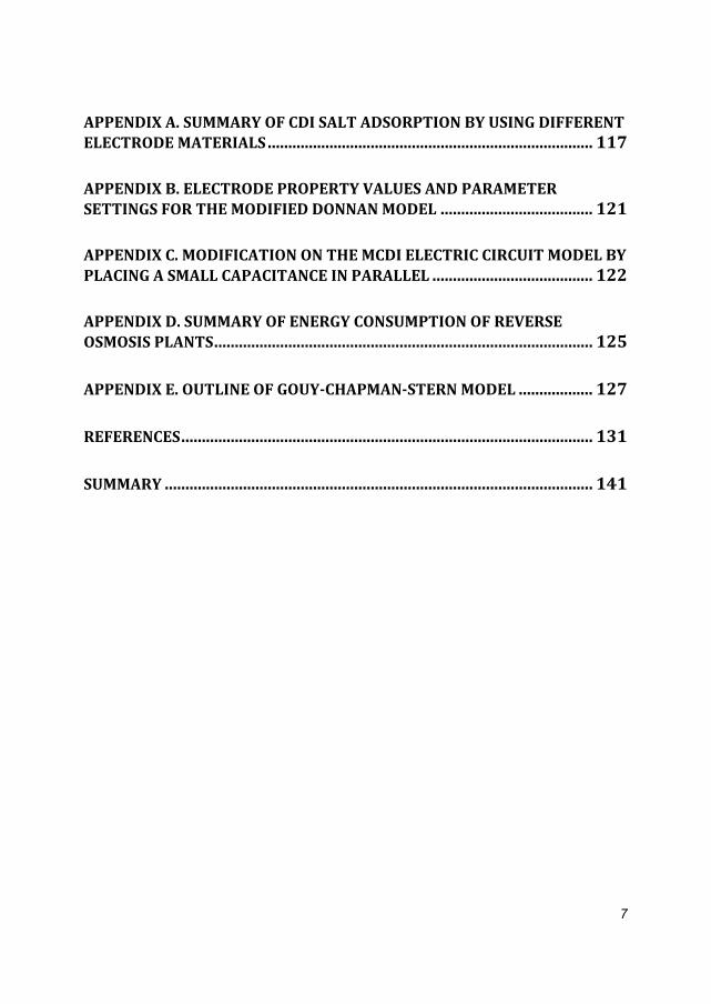
TableofContents
LISTOFPUBLICATIONS......................................................................................8
CHAPTER1.INTRODUCTION.............................................................................9 1.1 The challenge of fresh water supply ........................................................................... 10 1.2 Desalination technologies ......................................................................................... 11
1.2.1 Distillation ....................................................................................................... 11 1.2.2 Reverse Osmosis .............................................................................................. 12 1.2.3 Electrodialysis .................................................................................................. 12 1.2.4 Other desalination technologies ........................................................................ 13
1.3 Capacitive Deionization ............................................................................................ 13 1.3.1 History of capacitive deionization ...................................................................... 14 1.3.2 Electrode materials for CDI ................................................................................ 16 1.3.3 Geometries for CDI testing based on a two‐electrode layout ................................ 17
1.4 Membrane Capacitive Deionization ........................................................................... 20 1.5 Objectives ............................................................................................................... 21 1.6 Aim and outline of thesis .......................................................................................... 21
CHAPTER2.CHARACTERIZATIONOFPOROUSELECTRODESATEQUILIBRIUMUSINGTHEMODIFIEDDONNANMODEL.............................23
2.1 Introduction ............................................................................................................ 24 2.2 Experimental section ................................................................................................ 25 2.3 Theory of modified Donnan model ............................................................................ 30 2.4 Results and Discussion ............................................................................................. 37
2.4.1 Theoretical and experimental results for NaCl ..................................................... 37 2.4.2 Theoretical and experimental results for CaCl2, and NaCl/CaCl2 mixtures ............... 42
2.5 Conclusions ............................................................................................................. 46
CHAPTER3.TRANSPORTTHEORYOF(MEMBRANE)CAPACITIVEDEIONIZATION...................................................................................................47
3.1 Introduction ............................................................................................................ 48 3.2 General discussion of theory for CDI and MCDI ........................................................... 52 3.3 Mathematical description of theory ........................................................................... 54
3.3.1 Transport in the spacer and membrane .............................................................. 55 3.3.2 Electrodes and electrical double layers ............................................................... 60
3.4 Experimental setup and parameter settings for transport modelling of (M)CDI .............. 62 3.5 Results and discussion .............................................................................................. 65
3.5.1 Comparison of experimental results and theory for CDI ....................................... 65

6
3.5.2 Comparison of theory with experiments for salt adsorption and charge in CDI and
MCDI as a function of cycle time ................................................................................ 68 3.5 Conclusions ............................................................................................................. 72
CHAPTER4.ENERGYCONSUMPTIONANDCONSTANTCURRENTOPERATIONINMEMBRANECAPACITIVEDEIONIZATION..........................73
4.1 Introduction ............................................................................................................ 74 4.2 Experimental Section ............................................................................................... 75
4.2.1 Experimental setup........................................................................................... 75 4.2.2 Energy requirements ........................................................................................ 76 4.2.3 Dynamic charge efficiency ................................................................................. 77
4.3 Theory .................................................................................................................... 77 4.4 Results and Discussion ............................................................................................. 78 4.5 Conclusions ............................................................................................................. 86
CHAPTER5.OPTIMIZATIONOFSALTADSORPTIONRATEINMEMBRANECAPACITIVEDEIONIZATION............................................................................87
5.1 Introduction ............................................................................................................ 88 5.2 Materials and Methods ............................................................................................ 89 5.3 Results and discussion .............................................................................................. 91
5.3.1. Constant current (CC) operation of MCDI ........................................................... 91 5.3.2. Constant voltage (CV) operation of MCDI ........................................................... 98 5.3.3 Discussion...................................................................................................... 101
5.4 Conclusions ........................................................................................................... 104
CHAPTER6.DISCUSSIONSANDCONCLUSIONS.........................................105 6.1. Introduction ......................................................................................................... 105 6.2. Measurable properties of porous carbon electrodes and ion‐exchange membranes .... 106
6.2.1. Two porosities of porous carbon electrode ...................................................... 106 6.2.2. Membrane charge density .............................................................................. 107 6.2.3. Chemical attraction term for neutral salt adsorption at zero cell voltage ............. 107
6.3 Optimal data processing for maximum salt adsorption and energy consumption ......... 109 6.4. Energy consumption for producing fresh water and comparison with reverse osmosis 113 6.5 General conclusions and perspectives ...................................................................... 115
7
APPENDIXA.SUMMARYOFCDISALTADSORPTIONBYUSINGDIFFERENTELECTRODEMATERIALS...............................................................................117
APPENDIXB.ELECTRODEPROPERTYVALUESANDPARAMETERSETTINGSFORTHEMODIFIEDDONNANMODEL.....................................121
APPENDIXC.MODIFICATIONONTHEMCDIELECTRICCIRCUITMODELBYPLACINGASMALLCAPACITANCEINPARALLEL.......................................122
APPENDIXD.SUMMARYOFENERGYCONSUMPTIONOFREVERSEOSMOSISPLANTS............................................................................................125
APPENDIXE.OUTLINEOFGOUY‐CHAPMAN‐STERNMODEL..................127
REFERENCES....................................................................................................131
SUMMARY........................................................................................................141
8
ListofPublications In relation to this thesis
Zhao, R., Biesheuvel, P.M., Miedema, H., Bruning, H. & van der Wal, A. Charge Efficiency: A
Functional Tool to Probe the Double-Layer Structure Inside of Porous Electrodes and Application in
the Modeling of Capacitive Deionization. The Journal of Physical Chemistry Letters 1, 205-210 (2010)
Zhao, R., van Soestbergen, M., Rijnaarts, H.H.M., Van der Wal, A., Bazant, M. Z. & Biesheuvel, P.M.
Time-dependent ion selectivity in capacitive charging of porous electrodes. Journal of Colloid and
Interface Science 384, 38-44 (2012)
Zhao, R., Biesheuvel, P.M. & Van der Wal, A. Energy Consumption and Constant Current Operation
in Membrane Capacitive Deionization. Energy & Environmental Science 5, 9520-9527 (2012)
Zhao, R., Satpradit, O., Rijnaarts, H. H. M., Biesheuvel, P.M. & Van der Wal, A. Optimization of salt
adsorption rate in membrane capacitive deionization. Water Research 47, 1941-1952 (2013)
Biesheuvel, P.M., Zhao, R., Porada, S. & van der Wal, A. Theory of membrane capacitive
deionization including the effect of the electrode pore space. Journal of Colloid and Interface Science
360, 239-248 (2011)
Zhao, R., Porada, S., Biesheuvel, P.M., & van der Wal, A. Energy consumption in Membrane
Capacitive Deionization for different water recoveries and flowrates, and comparison with Reverse
Osmosis. Submitted to Desalination (2013)
Other publications
Brogioli, D., Zhao, R. & Biesheuvel, P.M. A prototype cell for extracting energy from a water salinity
difference by means of double layer expansion in nanoporous carbon electrodes. Energy &
Environmental Science 4, 772-777 (2011)
Porada, S., Zhao, R., Van der Wal, A., Presser, V. & Biesheuvel, P.M. Review on the Science and
Technology of Water Desalination by Capacitive Deionization. Progress in Materials Science, doi:
10.1016/j.pmatsci.2013.03.005 (2013)
Chapter 1
9
Chapter1Introduction
apacitive deionization (CDI) is a newly developed technique for water
desalination, where porous carbon is used as electrode material for ion
adsorption, which has tremendous potential in desalination of brackish water.
However, capacitive deionization is still in its developing stage, of which many
aspects need better understanding and in-depth investigation. This thesis deals with
characterizing the CDI system, comparing the classical CDI mode with the one
with ion exchange membranes (IEMs), i.e. membrane capacitive deionization
(MCDI), optimizing the performance of MCDI for different operational modes, and
looking into the energy consumption of the MCDI system.
In this introductory chapter, general background information will be given,
starting with the challenge to produce fresh water for the world’s steadily growing
needs, and an overview of the state-of-the-art desalination techniques. Afterwards,
it narrows down to the focus of this thesis, i.e. the CDI technology, of which the
history and development, and the carbon materials used will be elaborated. Finally
the objectives and the outline of this thesis will be depicted.
C
Introduction
10
1.1 The challenge of fresh water supply
Water, H2O, covering 71% of the earth’s surface, is of great importance in
maintaining the metabolism of any living creature. Although the total water storage
of the earth is 1.4 Gm3, 97.5% is saline water, and only 2.5% is fresh water. Table
1.1 exhibits a simple classification of natural waters in terms of their saline content,
TDS (Total mass of Dissolved Solids) [1].
Table 1.1 Water classification based on salinity content
Type Total dissolved solids (g/L TDS)
Fresh water Up to 1.5
Brackish water 1.5–10
Salt water > 10
Seawater 10–45
Accessible freshwater resources including river, lake and ground water occupy
only a tiny fraction of 0.26% of the total freshwater storage [2]. Because of the
growth of economy and population, withdraw of fresh water for agriculture,
industry and daily consumption of humanity is steadily increasing. By 2025, 1.8
billion people will be living in countries or regions with absolute water scarcity,
and two-thirds of the world’s population could be living under water stress
conditions [3]. With increasing groundwater extraction, salt water ingress in wells
and aquifers continues. As a consequence, providing clean fresh water in a safe,
inexpensive and energy-efficient manner is amongst the most important
technological challenges in the coming decades [4-6].

Chapter 1
11
1.2 Desalination technologies
Considering the larger amount of brackish water than that of fresh water in the
world, undoubtedly, it is particularly attractive to utilize the various brackish water
resources for human consumption in daily use, agriculture, and industry. Over
years, a number of desalination technologies have been developed, among which
distillation, reverse osmosis, and electrodialysis are the most commonly known and
widespread [7]. Here, these widely used techniques will be briefly explained.
1.2.1 Distillation
Distillation occurs on the basis of phase change of water, which requires a
significant amount of energy input under ambient conditions (water boiling
point=100 oC at 1 bar). In practice, the boiling point of water can be altered by
adjusting the atmospheric pressure to produce the maximum amount of water
vapour under controlled conditions. Today, among evaporative desalination
processes, Multi Stage Flash (MSF) desalination and Multiple Effect Distillation
(MED) are used world widely. In MSF, feed water evaporates in a series of
flashing chambers (countercurrent heat exchangers) with decreasing temperature
and pressure heated by a steam, which results in the production of large amount of
vapour that is then re-condensed on the external surface of a tube bundle. In MED,
evaporation occurs on the external surface of a tube bundle which is heated by
motive steam condensing inside the tubes. Vapour produced in one effect (stage)
then flows into the tubes of the next stage being used to evaporate more water at
lower pressure as well as lower temperature. Both MSF and MED can be coupled
to vapour recovery devices, in order to enhance the energy efficiency [1].

Introduction
12
1.2.2 Reverse Osmosis
Besides the phase change, the separation of fresh water from saline water can also
be accomplished by pressure-driven membrane processes. Among these processes,
Reverse osmosis is the most widely used, which occupies more than 70% market
share for seawater and brackish water desalination in Europe [8]. By pressurizing
saline water through a semi-permeable membrane that only allows the permeation
of water molecules but not ions or any other dissolved matter, a stream of pure
water can be produced as well as a brine stream [1, 8]. Feed pressure is required to
overcome the osmotic pressure on the feed side of the membrane. For seawater
desalination, the feed pressure commonly ranges from 60-80 bars [9], while for
brackish water, the figure is much lower (~20 bar) [10].
1.2.3 Electrodialysis
Like reverse osmosis, electrodialysis [11, 12] is also a membrane based
desalination means. However, instead of the usage of semi-permeable membrane,
ion-exchange membranes are used. An electrodialysis setup consists of a stack of
alternatingly placed anion and cation exchange membranes, with an anode at one
end of the stack and a cathode at the other end. During the desalination process, an
electrical current is applied between the two electrodes by an external power source,
e.g. a battery. Because of the applied electrical current, ions are forced to migrate
to their counter-electrode (electrode with the opposite charge, cations to the
cathode and anions to the anode). The anions can pass freely through the nearest
anion exchange membrane, but their further attempt to reach the anode is blocked
by the adjacent cation exchange membrane. Likewise, the cations migrate in the
opposite direction, through the nearest cation exchange membrane, but are then
blocked by the adjacent anion exchange membrane. As a result, concentrate and
dilute streams are formed in the space between the membranes alternatingly.
Chapter 1
13
Electrodialysis is often used for desalinating brackish ground water for use as
drinking water [13], and is used in the chemical process industry, in biotechnology
and in water pollution control as well [14].
1.2.4 Other desalination technologies
Besides above mentioned desalination means, there are also many novel
desalination technologies, and some of them are still in their infancy, for example
the production of frozen desalted water by removing the heat from salt solution [1],
forward osmosis that utilizes natural osmosis to dilute salt water using a draw
solution with higher osmotic pressure than the feed [15], and capacitive
deionization.
1.3 Capacitive Deionization
Capacitive deionization (CDI) is a technology for desalination and water
treatment in which salts and minerals are removed from salt water by applying
an electrical field between two oppositely placed porous carbon electrodes (Fig.
1.1), similar to supercapacitors [16]. Counterions are stored in the electrical double
layers (EDLs) which form at the solution interface in the micropores of the porous
electrodes, namely cations are stored in the negatively charged electrode (cathode)
and anions are stored in the positively charged electrode (anode).
The employed electrodes in our CDI setup are typically prepared from activated
carbon materials with internal areas for ion adsorption in the order of 1000 m2 per
gram (BET area), but other materials are also possible, which will be described in
general later in section 1.3.2. The two electrodes are separated by a thin open
structured “spacer”, or flow channel, through which the water flows. Upon
applying an electrical potential difference (“cell voltage”) or an electrical current

Introduction
14
between the two electrodes, anions are adsorbed into the anode and cations into the
cathode, thereby producing a freshwater stream. After the ion adsorption capacity
of the electrodes has been reached, the applied cell voltage can be reduced to zero
and a small concentrated salt stream is obtained in the ion release-step. In this way
the fresh water and the concentrated salt stream are produced intermittently.
Fig. 1.1. Schematic design of a cell for Capacitive Deionization. Upon applying a voltage difference
between two porous carbon electrodes, ions are attracted into the electrode, cations into the negative
electrode (cathode, on top), anions into the positive electrode (anode, bottom). As a result, desalinated
water is produced. [17]
1.3.1 History of capacitive deionization
In this section an overview of the early phase of CDI development in the 20th
century will be given. In 1960s, Blair, Murphy et al., who are the pioneers in the
CDI domain, have conceptualized ‘electrochemical demineralization of water’,
[18-21] . During that period, electrodes were classified into cation- and anion-
responsive types (analogous to cation- and anion-permeable membranes) according
to their “ion-responsiveness”, and it was assumed that ions could only be removed
from water when specific chemical groups present on the electrode surface are
either oxidized to form ionic bonds with cations in the aqueous phase or reduced to

Chapter 1
15
form ionic bonds with anions upon a cell voltage difference is applied. Some years
later Evans et al. [22] attempted to explain the fundamental ion removal
mechanism of CDI by the electrochemical reactions within the ion exchange
mechanism, and it was assumed that the efficiency of the salt removal was
determined by the concentration of surface groups.
However, nowadays salt ions being adsorbed in the electrical double layers
(EDLs) inside the porous carbon is the most prevalent view on the salt adsorption
mechanism of CDI among scientists. Thus, surface groups are considered less
relevant, and all electrodes are considered “ion-responsive” for all ions. This
modern view has its origin in 1970 when the concept of electrochemical
demineralization was made by Johnson et al. [23], where the theory of “potential-
modulated ion sorption”, similar to the electrical double layer (EDL) theory, was
identified as the actual mechanism responsible for ion removal. In the same study
the authors stressed that any Faradaic reaction that may occur at the interface
between the solid conductive material and the solution side may cause electrode
degradation, and from the performance efficiency point of view, these processes
are not essential when the current flow is mainly capacitive. A further study by
Johnson and Newman [24] described a porous electrode model to analyse ion
adsorption in porous carbons, and charge-voltage dependence, which concluded
that the ion capacity of the electrode depends on the electrical capacity of the
double layer, the available surface area, and the applied cell voltage. Following
this concept, extensive studies on this and other topics were initialized by Soffer,
Oren and co-workers in the early 1970s, and still continue up to the present time
[25-29]. In 1978, Oren and Soffer [26] introduced an idea of “four-action
electrochemical parametric pumping cycles” as an effective method to obtain a
precise separation between just desalinated water and concentrate (see in Fig. 1.3c).

Introduction
16
In 1990s, carbon aerogel materials developed by Farmer et al. drew a lot attention
[30]. Since then an increasing number of publications have been focusing on
developing effective carbon materials for water deionization. Modern carbon
materials for CDI will be briefly introduced in section 1.3.2.
1.3.2 Electrode materials for CDI
As it is the place where ions are stored, electrode plays an important role in the
CDI process. In theory electrodes can be fabricated from all conductive and porous
materials. However, the selection of electrode materials is normally based on the
cost, tunability of porosity, the specific surface area as well as the availability of
these materials. In the literature, activated carbons are by far the most used
materials due to their low costs (~50 $/kg), high specific surface area (1000–3500
m2/g), and high availability (can be derived from natural sources like coconut shells,
wood, coal, resins, etc.) [31-35]. Here, in this thesis a commercially available
activated carbon material (PAC MM™ 203, Materials and Methods LLC, USA) is
used throughout all following chapters. Apart from activated carbon, ordered
mesoporous carbons [36, 37], carbide-derived carbons [38, 39], carbon aerogels
[27, 30, 40-43], carbon nanotubes [44-46], and graphene [47], etc., can also be used
for salt adsorption in the CDI system. Fig. 1.2 provides a selection of images of
various carbons used for CDI applications. In Appendix A, we present an overview
of salt adsorption in the CDI system with different electrode materials, which
exhibits a broad range of salt adsorption capability from 0.6 to 15 mg salt/g
electrode weight.

Chapter 1
17
Fig. 1.2. Selection of carbon materials used for CDI. a) activated carbon (Norit DLC Super 30, Norit
Nederland B.V., the Netherlands), b) ordered mesoporous carbon [48], c) carbide-derived carbon
[49], d) carbon aerogels [50], e) multi-wall carbon nanotubes [44], f) graphene [51].
1.3.3 Geometries for CDI testing based on a two-electrode layout
The classical CDI-geometrical design is comprised of two oppositely placed
porous carbon electrodes (between 100 and 500 µm) with a small planar gap in
between which allows water flow along the electrodes. This design is known as
‘flow-by’ CDI, which is schematically sketched in Fig. 1.3. In this geometry, a

Introduction
18
typical electrode for laboratory scale experiments is in the range of 5x5 cm2 to
10x10 cm2. Such electrodes can be constructed either as freestanding thin films, or
can be coated directly onto a flexible current collector such as graphite foil [52, 53].
The planar gap between the electrodes can be an open channel, then typically at
least 1 mm in thickness [54], or can be constructed from a spacer material with a
high porosity and thickness typically between 100 – 300 µm. The geometry does
not strictly require water to enter from one end and to leave at the other. For
instance, in this thesis, the water enters from a hole in the centre of a square cell
radially, flows outward, and leaves the cell on all four sides, or the reverse.
The second geometry is known as the “flow-through” mode, which directs the
water straight through the electrodes, a method applied by Newman and Johnson in
Ref. [23, 24] and further developed by Suss et al. [55], see Fig. 1.3b. In this design
the feed water is pumped perpendicular to the layered structure, i.e., straight
through the larger pores in the electrodes. Compared to the classical “flow-by”
mode, this flow pattern can lead to a faster system response (rate of desalination),
because ions can direct migrate into the electrodes, instead of diffusing firstly from
the spacer channel into the electrodes [55].
The third approach is called “electrostatic ion pumping” [56], see Fig. 1.3c, a
method related to the classical technique of “parametric pumping”. In electrostatic
ion pumping [56], see Fig. 1.3c, feed water is pumped in from the top side,
desalinated when passing along the electrodes being stacked in the middle, and the
fresh water is then produced on the bottom side. Upon the electrodes are saturated,
the system can be regenerated via short-circuiting the electrodes. During the
regeneration, the water flow can be reversed, thereby creating a concentrated salt
stream (concentrate) on the top side. Thus, the advantage of the electrostatic ion
pumping is that always the fresh water and the concentrate can be produced at the
same time, unlike in CDI, where those two streams are produced sequentially.

Chapter 1
19
Finally a new design, called “wire-CDI” will be introduced. It employs
movable carbon rod electrode wires[57], see Fig. 1.3d. Instead of producing fresh
water and concentrate intermittently in the classical “flow-by” or the “flow-through”
mode, the fresh water and concentrate streams are separated at all times, right from
the start. In the wire-based approach, cell pairs are constructed from wires, or thin
rods, with anode wires positioned close to cathode wires. The wire pairs are firstly
submerged in the water and upon applying a voltage difference between the anode
and cathode wires, salt ions will be adsorbed into their counter electrodes, thereby
decreasing the salinity of this stream. After adsorbing salt, the assembly of wires is
lifted from the desalinated stream, and immersed into another water stream, upon
which the cell voltage is reduced to zero and salt is released. After the salt release,
the procedure can be repeated continuously in order to further decrease the salinity
in the first stream and increase that in the second stream.
anionscations
(a) (b)
(c) (d)
Fig. 1.3. Overview of most relevant CDI system geometries. (a) Flow-by mode, (b) Flow-through
mode, (c) Electrostatic Ion Pumping, (d) Desalination with wires. [17]

Introduction
20
1.4 Membrane Capacitive Deionization
Membrane Capacitive Deionization (MCDI) is one of the most promising
recent developments in CDI, which is also the main focus of this thesis. By
definition, MCDI is a combination of conventional CDI with ion-exchange
membranes (IEMs) placed in front of the electrodes, see Fig. 1.4. IEMs can be
positioned in front of one or both electrodes. IEMs have a high internal charge due
to covalently bound groups such as sulfonate or quarternary amines, which allows
easy access for one type of ion (the counterion) and block access for the ion of
equal charge sign (the co-ion). As will be explained in the thesis (Chapter 3 and 4),
addition of IEMs significantly improves desalination performance of the CDI-
process, in terms of salt adsorption, charge efficiency and energy consumption. The
membranes can be included as stand-alone films of thicknesses between 50 and
200 µm, or can be coated directly on the electrode with a typical coating thickness
of 20 m [52, 58-61].
Fig. 1.4. Schematic design of a cell for Membrane Capacitive Deionization, MCDI, where in front of
the cathode a cation-exchange membrane is placed, while an anion-exchange membrane is placed in
front of the anode.[17]

Chapter 1
21
1.5 Objectives
The objectives of the thesis are to understand the fundamental ion adsorption at
equilibrium mechanism of the capacitive deionization technology, to compare the
desalination performance between capacitive deionization and membrane
capacitive deionization in terms of salt adsorption, charge efficiency, and energy
consumption, and to optimize the operational mode in order to achieve the highest
salt adsorption rate.
1.6 Aim and outline of thesis
The scope of this thesis covers many perspectives. Firstly it is aimed to investigate
a way to probe the fundamental properties of porous carbon electrodes for salt
adsorption in capacitive deionization (CDI) process. Why, how and where can the
salt ions be adsorbed? Therefore, in Chapter 2, a modified Donnan model based
on electrical double layer (EDL) theory is proposed, and theoretical results of salt
adsorption and charge, etc. at equilibrium state are compared with experimental
data. Through the comparison, the EDL properties, namely the Stern layer
capacitance, and the micropore volume, can be identified. Those properties are
afterwards integrated into a two-porosity (intraparticle micropores and interparticle
macropores) transport model, which describes electrokinetics of ion transport
during the ion-adsorption step when a voltage is applied between the electrodes,
and also during the ion-release step when a short-circuiting condition (zero-volt) is
applied.
What happens to the CDI performance when ion-exchange membranes (IEMs)
are employed? Can the membrane improve the salt adsorption capacity? As a
continuation of Chapter 2, Chapter 3 provides answers to those questions by
conducting an in-depth comparison between CDI and membrane capacitive
deionization (MCDI), both experimentally and theoretically for a series of
Introduction
22
adsorption electrical voltages. It is concluded that MCDI overwhelms CDI not only
in salt adsorption capacity but also in charge efficiency. Also it is found that the
fact MCDI adsorbs more salt ions than CDI is because the interparticle space
(macropores) can also be utilized for salt storage during adsorption because of the
presence of the IEMs.
Until now most experiments of either CDI or MCDI were conducted by
applying a constant voltage difference between the electrodes during ion-
adsorption. However, is it also possible to operate the system by applying a
constant current? Chapter 4 presents the way to operate (M)CDI by applying a
constant electrical current. This constant current operation may be more suitable
for commercial applications than constant voltage operation, due to its capability to
produce an effluent with unchangeable and tuneable effluent concentration. In
addition the energy consumption of MCDI and CDI for both operational modes
was also compared, which demonstrates that MCDI is more energy-efficient than
CDI.
To follow up, Chapter 5 discusses how to optimize the operation of MCDI for
both constant current and constant voltage operational modes in order to achieve
highest salt adsorption in a given time period. This chapter can be used as a
guideline for designing the most optimum MCDI operational mode for a particular
application.
To conclude, Chapter 6 summarizes and discusses all achievements of the
research, discusses possible modifications, compares the energy consumption of
MCDI with that of Reverse Osmosis, and recommends future research perspectives.

Chapter 2
23
Chapter2CharacterizationofporouselectrodesatequilibriumusingthemodifiedDonnanmodel
apacitive deionization (CDI) is a novel desalination technology where ions
are adsorbed from solution into the electrical double layers formed on the
electrode/solution interface in the carbon micropores inside two face-to-face placed
porous electrodes. A key property of the porous electrode is the charge efficiency
of the electrical double layer defined as the ratio of equilibrium salt adsorption
over electrode charge for the 1:1 salt, such as NaCl. We present experimental data
for as a function of voltage and NaCl salt concentration and use this data set
together with the modified Donnan model to characterize the double layer structure
inside the electrode, and determine the microporosity for ion adsorption. In this
research we give accurate experimental assessment of these two crucial properties
for the NaCl solution, which enables more structured optimization of electrode
materials for desalination purposes. In addition, we also present the use of modified
Donnan model for more complicated conditions, e.g., CaCl2 solution and
NaCl/CaCl2 mixtures.
C
Characterization of porous electrodes at equilibrium using the modified Donnan model
24
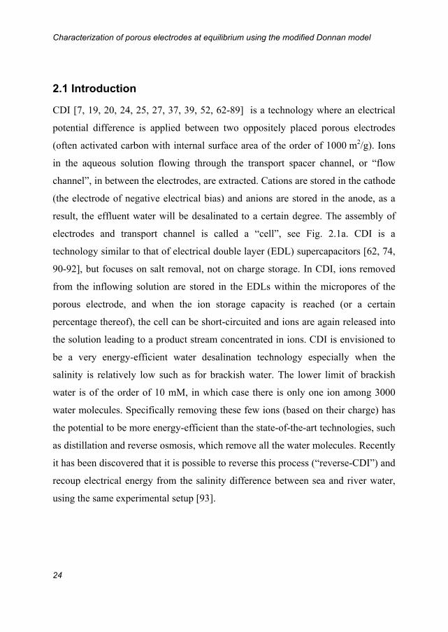
2.1 Introduction
CDI [7, 19, 20, 24, 25, 27, 37, 39, 52, 62-89] is a technology where an electrical
potential difference is applied between two oppositely placed porous electrodes
(often activated carbon with internal surface area of the order of 1000 m2/g). Ions
in the aqueous solution flowing through the transport spacer channel, or “flow
channel”, in between the electrodes, are extracted. Cations are stored in the cathode
(the electrode of negative electrical bias) and anions are stored in the anode, as a
result, the effluent water will be desalinated to a certain degree. The assembly of
electrodes and transport channel is called a “cell”, see Fig. 2.1a. CDI is a
technology similar to that of electrical double layer (EDL) supercapacitors [62, 74,
90-92], but focuses on salt removal, not on charge storage. In CDI, ions removed
from the inflowing solution are stored in the EDLs within the micropores of the
porous electrode, and when the ion storage capacity is reached (or a certain
percentage thereof), the cell can be short-circuited and ions are again released into
the solution leading to a product stream concentrated in ions. CDI is envisioned to
be a very energy-efficient water desalination technology especially when the
salinity is relatively low such as for brackish water. The lower limit of brackish
water is of the order of 10 mM, in which case there is only one ion among 3000
water molecules. Specifically removing these few ions (based on their charge) has
the potential to be more energy-efficient than the state-of-the-art technologies, such
as distillation and reverse osmosis, which remove all the water molecules. Recently
it has been discovered that it is possible to reverse this process (“reverse-CDI”) and
recoup electrical energy from the salinity difference between sea and river water,
using the same experimental setup [93].
Chapter 2
25
+ ++
+ +
-
+
+
+
- -
- -
- - -
Stern layer,St
d
(b)
Water OUT
Water IN
Current collectorCarbon electrodeSpacer
+
(a)
Fig. 2.1. (a) Schematic view of one CDI-cell, (b) graphical description of the modified Donnan model
and the two types of porosities inside the porous carbon electrodes. pmi is microporosity, cj,mi is
concentration of a certain type of ions j in the micropores, pmA is macroporosity, cmA is concentration
of salt in the macropores, ∆st is the potential drop over the Stern layer, and ∆d is the electrostatic
potential difference between the micropores and macropores.
To understand the CDI process, the first step is to characterize the porous
electrodes which are the core compartments of the cell. In this work we will show
how we characterize the porous electrodes, in other words, derive the fundamental
properties, e.g., charge efficiency (), volumetric Stern Layer Capacitance (CSt,vol)
and microporosity of the electrode (pmi) by using the experimental equilibrium data
of salt adsorption and charge as a function of cell voltage and salt concentration
together with the ‘modified Donnan model’ which is a novel approach from the
electrical double layers (EDLs) theory. Both theoretical and experimental results of
salt adsorption and charge at equilibrium state will be given, not only for single
symmetric (1:1) electrolyte, NaCl, but also the equilibrium adsorption for
asymmetric electrolyte, for instance CaCl2 (1:2 electrolyte), and mixtures of NaCl
and CaCl2 can be reproduced by the modified Donnan model.
2.2 Experimental section
Experimental data were obtained in a laboratory-scale CDI-stack with 8 cells.
As shown in Fig. 2.1a, each cell consists of 2 graphite current collectors (Cixi

Characterization of porous electrodes at equilibrium using the modified Donnan model
26
Sealing Spacer Material Factory, Ningbo City, China, thickness =250 m, same in
all chapters in this thesis), 2 porous carbon electrodes (PAC MM™ 203, Materials
and Methods LLC, USA. Note that it is the standard and the only electrode material
being used for all experiments in this thesis, of which the thickness elec, the total
mass mtot, and the electrode density e vary between different batches in this work,
see Appendix B), and a polymer spacer (Glass fibre prefilter, cat no. AP2029325,
Millipore, Ireland, =250 m, same in all chapters in this thesis) in between the
two electrodes. The graphite current collectors are alternatingly positively or
negatively biased. All materials are cut in pieces of 6x6 cm2 dimension and
assembled, after which the entire stack of all layers is firmly pressed together and
placed in a Teflon (PTFE) housing. The photos of experimental stack and its
compartments are shown in Fig. 2.2. An aqueous solution (NaCl, CaCl2 or the
mixtures of NaCl and CaCl2) is continuously pumped through a small squared
opening (1.5x1.5 cm2) located in the exact middle of the stack, and goes radially
outward through the spacer layers during the whole experiment period, see Fig.
2.1a (in reality the water flows in from opening “2” and flows out from opening
“1”, see Fig. 2.2a), or the solution is pumped from all sides of the stack inward
through the spacer layers and flows out from the opening in the middle (in reality,
the water flows in from opening “1” and flows out from opening “2”; in this
chapter, only data from Fig. 2.5 were obtained with this flow direction). There is no
difference between these two flow directions with regard to the equilibrium total
salt adsorption and total charge transferred, which will be discussed later.

Chapter 2
27
Fig. 2.2. (a) Photograph of the experimental CDI stack, (b) front view of cells stacked in the housing,
(c) Sequenced components of one CDI, from left to right: graphite current collector, porous carbon
electrode, glass fibre spacer, porous carbon electrode, and graphite current collector.

Characterization of porous electrodes at equilibrium using the modified Donnan model
28
The experiments consist of two steps: ion-adsorption step and ion-release step.
Together they are called one cycle. During the ion-adsorption step, a fixed
electrical voltage is applied between the two electrodes. Because of the voltage
difference across the cell, ions in the spacer channel are adsorbed into the
electrodes. As a result, the effluent concentration ceff decreases, reaches the lowest
value, and then gradually increases, see Fig. 2.3a. At the same time, the electrical
current decreases towards zero, see Fig. 2.3b. The voltage difference is applied
sufficiently long (for single salts 0.5 hr to 2 hrs, for the mixtures up to 5 hrs) in
order to assure that the current drops to zero (except for a leakage current) and the
effluent salt concentration (ionic strength) returns to the inlet value, when the
electrodes are saturated with ions. In this way we ascertain that the double layers
everywhere within the electrodes are at equilibrium with the bulk salt solution, of
which we know the salt concentration (ionic strength). During the ion-release step,
a zero voltage is applied for the same time as the ion-adsorption step. In response,
the ions adsorbed in the porous carbon electrode will be released into the spacer
channel creating a temporary concentrated stream (Fig. 2.3a). After all adsorbed
ions are released and because of the continuous replacement of the salt solution in
the spacer channel by the influent, the concentration will drop again to its initial
value, see Fig. 2.3a. It is also shown in Fig. 2.3b that the electrical current during
the ion-release step will increase from a negative value towards zero.
The electrical voltage and current are applied and measured on-line using a
potentiostat (Iviumstat standard, Ivium Technologies, The Netherlands). The
measured current signal is integrated with time to obtain the electrode charge, F,
see Fig. 2.3b. In all our experiments, a leakage current, observed as a constant
small current (~ several mA) in both ion adsorption- and desorption-step is
subtracted from the data. This procedure ensures that the total charge transferred in
one direction during ion removal, equals the charge transferred in the opposite
direction during ion-release, in other words, the “charge balance” is obtained.
Chapter 2
29
There are two ways to measure the effluent salt (or ion) concentration. First, if the
influent stream only contains a single salt, e.g., NaCl or CaCl2, the conductivity of
the effluent stream can be simply measured on-line, and be converted into salt
concentration according to a calibration curve of salt concentration vs. conductivity.
Effluent pH is also measured and used to correct the measured conductivity. This is
because the total conductivity of a solution is a sum of individual conductivity of
all ions present in the solution, according to the Nernst-Einstein equation
, where F is the Faraday constant, R is the ideal gas
constant, T is the thermodynamic temperature, z, D and c are the valence, diffusion
coefficient and concentration of a specific ion j in the solution, respectively. When
the pH is close to 7, the contribution from protons and hydroxyl-ions is rather small
(since there concentrations are very low compared to the concentration of salts in
the solution), thus can be safely omitted. However, the pH varies during our
experiments, and sometimes it can reach very acidic (<4) or basic (>10) condition,
then the presence of protons (H+) or hydroxyl-ions (OH) will influence the total
conductivity in the effluent solution strongly and cannot be ignored any more. Thus
their contributions have to be subtracted (both H+ and OH concentrations can be
calculated from the measured pH value) from the measured conductivity of the
solution, and afterwards, we can easily obtain the accurate concentration of the salt
itself. For the NaCl/CaCl2 mixtures, the concentration of each ion cannot be
directly converted from the conductivity because the Na+/Ca2+ ratio vary during the
experiments for the multi-ion condition. Thus samples (~2 mL each) from the
effluent stream were taken during the whole experiments with a time interval of
several seconds, and then ion concentrations were measured by inductively coupled
plasma optical emission spectrometry (ICP-OES). In the end, the concentrations of
Na+ and Ca2+ ions can also be plotted as a function of time, as is shown in Fig. 2.7.
The salt adsorption salt can be calculated from integrating the difference between
Λ 2
0 2m j j j
j= F z D cR T

Characterization of porous electrodes at equilibrium using the modified Donnan model
30
the influent salt concentration and the effluent salt concentration (cin-ceffluent) with
time and multiplying with the solution flowrate , see Fig. 2.3a. Obviously, the
amount of salt adsorbed must equal the amount of salt released, a condition which
we checked to hold during our experiments. We calculate from the independent
measurement of the equilibrium salt adsorption, salt, and equilibrium charge
(=F/F, F is Faraday constant).
Fig. 2.3. Experimental results of (a) salt effluent concentration ceff (solid line), salt influent
concentration cin (dots) and (b) electrical current as a function of time (solid line). Water flowrate =
60 mL/min, influent NaCl concentration is 5 mM, cell voltage Vcell = 1 V is applied for half hour, and
afterwards the cell is short-circuited (zero voltage is applied) for another half hour.
2.3 Theory of modified Donnan model
In this section we present a model for equilibrium ion adsorption and charge
in the CDI cell. The ion adsorption capacity of the electrodes used in CDI is
directly related to the volume of micropores. Therefore the electrodes typically are
made of porous activated carbons with high porosity, which in our case are
obtained via the fitting procedure by the modified Donnan model. Just as important
is the nanoscale structure of the electrical double layers (EDLs) which form within
-1.2-0.8-0.4
00.40.8
0 900 1800 2700 3600
02468
10
Conc
entr
atio
n (m
M)
Curr
ent (
A)
cin = 5 mMVcell = 1 V
Time (s)
Salt adsorbed
Salt released
Charge
Short-circuitVcell = 0 V
(a)
(b)
cin
ceff

Chapter 2
31
the micropores of the electrode. To understand ion adsorption within the EDLs,
previously the classical Gouy-Chapman-Stern (GCS) model was used to describe
equilibrium adsorption of salt and charge in porous electrodes as a function of cell
voltage and ion strength [63, 64, 93-96]. The GCS-model assumes a diffuse layer
(besides an inner, Stern layer) which has a typical extension into free solution of
several times the Debye length (which is ~3 nm at 10 mM salt concentration). Note
that the GCS model will be briefly explained in Appendix E. However, the
micropores in porous activated carbon electrodes are small (less than 2 nm) and
diffuse layers must be overlapping strongly [74, 75, 97]. This led us to use a novel
approach which is called “modified Donnan (mD) model”, see Fig. 2.1b. In the mD
model, it is assumed that within the carbon particle the pore space has a constant
electrostatic potential. This is a reasonable assumption because the Debye length is
in most situations much larger than the micropore size. Compared to the classical
Donnan approach used for charged gels, membranes, sedimentation of charged
colloids [98], clays [99, 100] and porous electrodes [101], we make two
modifications: firstly, we include the charge-free Stern layer in between the pore
solution and the carbon matrix, and secondly we consider an additional attractive
force for the ion to go from the macropores into the micropores, described by a
chemical attraction of strength att. In this way it will be possible to include in the
model the fact that even at zero voltage, neutrally adsorbed salt already exist in the
carbon material. This adjustment is also required because as shown in Fig. 2.4b (to
be discussed further on) we measure a co-ion expulsion from the carbon particles,
which cannot be explained in the absence of the chemical attraction (i.e., for att=0).
In the present work we use for the cation and the anion the same value for att to
preserve symmetry between the two electrodes in the theory, but it is more likely
that in reality the two numbers are different for each ion, and will also be different
for different ions of the same sign [102].

Characterization of porous electrodes at equilibrium using the modified Donnan model
32
Since we model a CDI cell consisting of two electrodes, firstly the voltage
drop between the two electrodes across the cell, Vcell = Vanode – Vcathode, has to be
explained. In this thesis the CDI cell, and the MCDI cell in later chapters are
assumed to be perfectly symmetrical, which means equal values for electrode mass,
porosities p, volumetric Stern capacity CSt,vol, and chemical attraction att are taken
for both electrodes. In addition, no pre-charge on the electrode exists. An overall
equation to express the distribution of the cell voltage over all elements between in
the cell is given by
(2.1)
where Vcell is the cell voltage, VT is the thermal voltage (=RT/F~25.7 mV at room
temperature), all ’s are dimensionless voltage drops for different elements in the
sub-cell: sp is the voltage drop across the spacer channel, elec is the potential
drop in the electrode, and d and St are Donnan potential and the Stern layer
potential in the micropores, to be discussed further on. Note that under the
equilibrium conditions, there is no current between the two electrodes, which
means the voltage drop across the spacer channel (sp) and in the electrode (elec)
vanishes. These terms, sp and elec, will be elaborated later in the (M)CDI
process model in Chapter 3, as they are changing variables in relation to current
which are used to model the capacitive deionization process. Therefore Eq. 2.1 can
be simplified to
(2.2)
Eq. 2.2 is a general equation which can be used for any combination of ions in the
electrolyte. When only a simple 1:1 salt, NaCl, as the electrolyte is used, and equal
masses of electrode are used without chemical pre-charge [88], the voltage drops in
the micropores for anode and cathode can be assumed to be mirror images of one
another (only the sign is different). Thus the voltage drop across the cell between
two electrodes can be further simplified to
cell T d St anode elec,anode sp elec,cathode d St cathode/ ( ) ( ) V V micropores, micropores,
cell T d St d Stmicropores,anode micropores,cathode/ V V

Chapter 2
33
(2.3)
Next, within the electrodes we assume that the porous carbon electrode
consists of two types of porosities, macropores and micropores. The macropores,
with porosity of pmA (macropore volume per unit total electrode volume), are
interparticle space, where the transport of ions across the electrode takes place. The
micropores are where the counterions are preferentially stored, and where the
electrical double layers (EDLs) form. The pore size of the micropores is typically a
few nanometers.
In the macropores, the sum of the product of charge number and concentration
of all ions (j denotes a specific type of ions) is always zero. In the case
of a single symmetric electrolyte, e.g., NaCl, ccation,mA has the same concentration as
canion,mA, thus the salt concentration csalt (per unit of macropore volume) is equal to
the concentration of both cation and anion. In the equilibrium state (electrodes are
saturated with ions for a given influent salt concentration in the spacer channel and
a fixed cell voltage), the salt concentration in the macropores cmA is the same as the
influent salt concentration (bulk concentration). And thus, for modelling salt
adsorption and charge at equilibrium state, the macropores can be omitted.
Micropores are the pores inside the carbon particles, which have a porosity of pmi
(micropore volume per unit total electrode volume), in which the cation
concentration, ccation,mi can differ from the anion concentration, canion,mi (ion
concentration per unit of micropore volume). As the size of the micropores is
smaller than that of the Debye length (a length scale to characterize the thickness of
the diffuse part of the double layer in the classical Gouy-Chapman-Stern theory for
a single double layer), the EDLs will overlap strongly, which influences the ion
distribution. This allows us to use the mD approach of assuming a constant
electrostatic potential in the micropore space relative to that in the macropores, d,
1cell T d St2 micropores
/V V
j,mAjj
z c
Characterization of porous electrodes at equilibrium using the modified Donnan model
34
and to relate the ion concentration in the micropores to that in the macropores, by
assuming equal chemical potential of ions in micro- and macropores, according to
, (2.4)
where cj,mA is the macropore concentration of a specific type of ions (for solution
containing only symmetric salt, e.g., NaCl, cj,mA is equal to the salt concentration
cmA in the macropores), zj is the charge number of ions, for example, zj = +1 for
Na+, and zj = -1 for Cl-, and where att is an attractive term which quantifies the
chemical attraction between ions and the carbon material. In order to keep
symmetry and simplicity in the present model, we will use the same value of att
for both the cation (Na+) and the anion (Cl-), though in a generalized model this
assumption can be relaxed. In Eq. 2.4, d is the Donnan potential difference
between inside (micropores) and outside (macropores) of the porous carbon
particle. The sum of the concentration of each ion multiplied by its charge number
is defined as the ‘charge concentration’, which is negative in the anode, and
positive in the cathode. At Eq. 2.5, this ionic charge is assumed to be
homogenously distributed across the electrode without gradients, which is locally
compensated by an equal amount of electronic charge in the carbon matrix (with
opposite sign). In addition, as charge neutrality always holds in the micropores, the
volumetric charge density can be defined as
. (2.5)
According to the Donnan approach, the EDLs inside the micropores of the porous
electrode are composed of the electrolyte-filled pore, where ions are accumulated,
and a charge-free Stern layer being located on the surface of the micropores, where
no ion is present. The electrical potential difference across the Stern layer ∆st is
related to the charge concentration ccharge,mi, given by the Gauss equation, , (2.6)
j,mi j,mA j d attexp zc c
charge,mi jj
c z c j,mi
charge,m i T St St,volc F V C
Chapter 2
35
where F is the Faraday constant (96485 C/mol), and Cst,vol is the volumetric
capacitance of the Stern layer. For CSt,vol, we use the empirical expression
, (2.7)
where the second term makes CSt,vol go up slightly with micropore charge, which
can be explained by the higher attractive force that acts across the Stern layer at
high charge [103, 104]. The set of equations above describes the ion distribution in the EDLs in the
micropore of the electrodes at the equilibrium state, and thus predicts the total ion
concentration in the micropores and the micropore charge density. These
micropore concentrations can be converted to measurable properties, namely the
charge F in C/g and in total ions adsorbed i (mol/g) by multiplying with the
geometry factor, to be explained below. Note that in this thesis, charge is either
described by F in C/g or by charge expressed in mol/g. They are related
according to F=F where F is Faraday’s constant, F=96485 C/mol.
To get the ion adsorption j in a two electrode cell for one specific ion, we
need to first add up its concentrations from both anode and cathode, and then
multiply with the geometry factor 1
2 -1
mi ep , where pmi is the microporosity of the
electrode, ρe is the overall mass density of the electrode, and 2 denotes an average
property for the two electrodes), the adsorption of a specific ion is given by
, (2.8)
where the superscript ‘0’ refers to the ion concentration at a cell voltage of Vcell=0.
For 1:1 salts like NaCl, salt = Na = Cl. In case of symmetry, the concentration of
adsorbed Na+ at one electrode is equal to the amount of adsorbed Cl- at the other
electrode. For instance, cNa,mi,anode = cCl,mi,cathode, and cNa,mi,cathode = cCl,mi,anode. Thus
2St,vol St,vol,0 charge,miC C c
0 0j
1
2 anode cathode
p c c c cj,mi j,mi j,mi j,mi-1
mi e

Characterization of porous electrodes at equilibrium using the modified Donnan model
36
based on Eqs. 2.4 and 2.8, the salt adsorption can be further simplified to
, (2.9)
Similarly for the equilibrium ionic charge, the general equation is given by
, (2.10)
and for the 1:1 salt, together with Eq. 2.4, Eq. 2.10 can be converted to
. (2.11)
Being a ratio of salt adsorption to charge transferred onto the electrodes, the charge
efficiency is defined as
. (2.12)
Eqs. (2.9), (2.11), (2.12) present the way to obtain values for salt, , and Λ by data
analysis. Combing these equations with Eq. 2.4 defined in the EDL mD model,
Eqs. (2.9) and (2.11) can also be expressed as
, (2.13)
. (2.14)
Taking the ratio of Eq. 2.13 over Eq. 2.14, the charge efficiency is then calculated
as
. (2.15)
0 0salt
1
2 p c c c ccounter,mi counter,mi co,mi co,mi
-1mi e
j
j
1 1
2 2 p c p z ccharge,mi j,mi
-1 -1mi e mi e
1
2 p c c-1
mi e counter,mi co,mi
salt=
salt att dcosh 1 p cmA-1
mi e exp
att dsinh p cmA-1
mi e exp
d=tanh2
Chapter 2
37
2.4 Results and Discussion
2.4.1 Theoretical and experimental results for NaCl
Previous studies on porous electrode characterization focused on electrode charge
(or, capacitance), often only at low cell voltages and for one, often high value of
the ionic strength. Though from such a limited data set it is in principle possible to
simultaneously derive the effective microporosity for ion storage, pmi, and the Stern
layer capacity, CSt, this is relatively inaccurate and has not been applied much.
Therefore, questions like which part of the activated carbon is actually available for
ion and charge storage, and do only pores in a certain size-range contribute to the
adsorption process, are still a matter of debate. Related to that, available
experimental data can hardly be used to accurately validate models for the EDL
structure of porous materials. Obviously, the current situation hampers the design
and effective optimization of (the structure of) electrode materials, for instance for
desalination purposes.
In this section we analyse an alternative procedure that instead of only
focusing on capacitance considers and combines data for charge with data for the
equilibrium salt adsorption from solution into the EDLs inside the electrode, salt.
Importantly, and salt are recorded simultaneously and independently. At first
sight one may have the impression that measuring salt simultaneously with will
be superfluous. This idea may arise from the assumption that each electron charge
will be fully charge-balanced by counterion adsorption. If so, this would imply
indeed that the transfer of one electron from one electrode to the other is
accompanied by the precise removal of one salt molecule out of the bulk solution.
This is however not the case because simultaneously with counterion adsorption,
co-ions are excluded from the double layer [24, 25, 63, 64, 69, 73, 93, 105]. The
effect of co-ion exclusion reduces the ratio of salt over , a ratio which we call the

Characterization of porous electrodes at equilibrium using the modified Donnan model
38
charge efficiency, . Theoretically, for very low potentials in the electrode
micropores, counterion adsorption and co-ion desorption are actually of equal
importance, i.e., for each electron transferred, there is half a cation adsorbed and
half an anion desorbed and thus will be close to zero, while for very high
potentials the limit is approached that counterion adsorption fully compensates the
electron charge and 1. As we will show, data for as a function of voltage and
ionic strength are an excellent probe to test models for the structure of the double
layer inside the porous electrode, without prior knowledge of the micropore
porosity for ion adsorption. Actually, after having established that a certain double
layer model accurately describes data for , the micropore porosity pmi can be
directly determined from a simple fit to the full data sets of both salt and . The
use of to determine double layer properties points to the fact that salt adsorption
per volume is a basic characteristic of double layers, as much as electrode charge,
independent of electrode porosity, weight or density.
Thus, the objective of the present chapter is to show that both pmi and CSt,vol,0
(volumetric Stern layer capacitance at low charge limit) of porous electrodes can be
accurately derived experimentally from two independently obtained data sets for
equilibrium salt adsorption and electrode charge, both assessed as a function of
ionic strength and cell voltage. These two parameters, in turn, are used as input
parameters in an electrokinetic CDI process model in Chapter 3. Note that the
theoretical parameter settings (CSt,vol,0, att, and pmi) for data in Figs. 2.4, 2.5 and
2.6 are given in Appendix B.
Fig. 2.4a shows measured values for based on data for equilibrium charge
and salt adsorption salt, as a function of cell voltage and ionic strength. These
experimental findings confirm the behaviour of predicted by Donnan theory in
that increases with increasing cell voltage, and, in addition, that at each cell
voltage, is higher when the ionic strength is lower. For the theoretical curves in

Chapter 2
39
Fig. 2.4a, we use an optimized set of values of CSt,vol,0, att and (Appendix B),
which results in a fairly good model fit for the charge efficiency. The micropore
porosity pmi now immediately follows from the model fitting to the full data sets of
F (Fig. 2.4c) and salt (Fig. 2.4d), which are well described using a value of pmi~37%
of the total electrode volume, which is a very realistic number.
0
5
10
15
20
25
30
35
0 0.2 0.4 0.6 0.8 1 1.2 1.4
20 mM
5 mM
0
0.05
0.1
0.15
0.2
0.25
0 0.2 0.4 0.6 0.8 1 1.2 1.4
20 mM
5 mM
(c) F (d) salt -200
0
200
400
600
800
counterions
co-ions
20 mM
20 mM5 mM
5 mM(a) Λ (b)
Cha
rge
effic
ienc
y C
harg
e (C
/g)
Sal
t ads
orpt
ion
(mm
ol/g
) M
icro
pore
ion
conc
entr
atio
n (m
M)
Cell voltage (V) Cell voltage (V)
0
0.2
0.4
0.6
0.8
1
20 mM
5 mM
Fig. 2.4. (a) Charge efficiency as a function of cell voltage for 5 mM and 20 mM NaCl solution [106].
(b) Concentration of counterions and co-ions in porous carbon micropores [107]. (c) Equilibrium
electrode charge as a function of cell voltage and ionic strength [106]. (d) Equilibrium salt adsorption
as a function of cell voltage and ionic strength [106]. (diamonds: 5 mM; triangles: 20 mM; lines:
theory curves). Theoretical curves are based on Eqs. 2.1-2.12. In panel (b) concentrations are given
per unit micropore volume, relative to the adsorption at zero cell voltage.
Characterization of porous electrodes at equilibrium using the modified Donnan model
40
The dashed line in Fig. 2.4c identifies the differential capacitance in the low-
voltage limit, CD,V0 which is ~56 F/g when defined per single electrode mass and
based on half the cell voltage, as usual in literature of electrodes for electrical
double layer capacitors (EDLCs). This result is in the range of reported literature
values [108, 109]. Furthermore, Fig. 2.4c shows that CD,V0 is an underestimate of
CD-values at higher voltages and that it is a function of ionic strength.
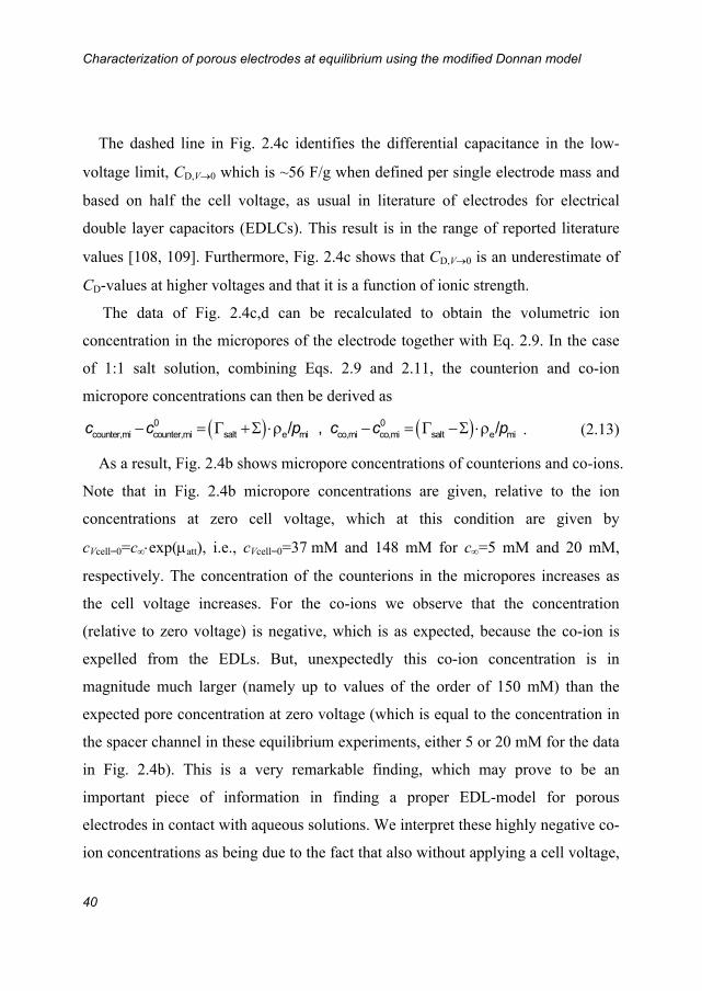
The data of Fig. 2.4c,d can be recalculated to obtain the volumetric ion
concentration in the micropores of the electrode together with Eq. 2.9. In the case
of 1:1 salt solution, combining Eqs. 2.9 and 2.11, the counterion and co-ion
micropore concentrations can then be derived as
. (2.13)
As a result, Fig. 2.4b shows micropore concentrations of counterions and co-ions.
Note that in Fig. 2.4b micropore concentrations are given, relative to the ion
concentrations at zero cell voltage, which at this condition are given by
cVcell=0=cexp(att), i.e., cVcell=0=37 mM and 148 mM for c=5 mM and 20 mM,
respectively. The concentration of the counterions in the micropores increases as
the cell voltage increases. For the co-ions we observe that the concentration
(relative to zero voltage) is negative, which is as expected, because the co-ion is
expelled from the EDLs. But, unexpectedly this co-ion concentration is in
magnitude much larger (namely up to values of the order of 150 mM) than the
expected pore concentration at zero voltage (which is equal to the concentration in
the spacer channel in these equilibrium experiments, either 5 or 20 mM for the data
in Fig. 2.4b). This is a very remarkable finding, which may prove to be an
important piece of information in finding a proper EDL-model for porous
electrodes in contact with aqueous solutions. We interpret these highly negative co-
ion concentrations as being due to the fact that also without applying a cell voltage,
0 0counter,mi counter,mi salt e mi co,mi co,mi salt e mi/ , / c c p c c p
Chapter 2
41
there is salt adsorption in the porous carbon particles due to a chemical affinity of
the ions with the porous carbon. Upon applying the voltage, the co-ions of these
chemically adsorbed salt molecules are expelled. This effect can only be found by
using non-zero values of the attractive term att. This assumption of a chemical
attraction of ions into the micropores of activated carbon particles is supported by
the fact that porous carbons are known to adsorb ions, also in the absence of an
applied voltage [86].
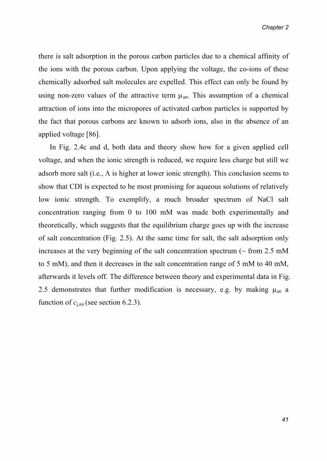
In Fig. 2.4c and d, both data and theory show how for a given applied cell
voltage, and when the ionic strength is reduced, we require less charge but still we
adsorb more salt (i.e., is higher at lower ionic strength). This conclusion seems to
show that CDI is expected to be most promising for aqueous solutions of relatively
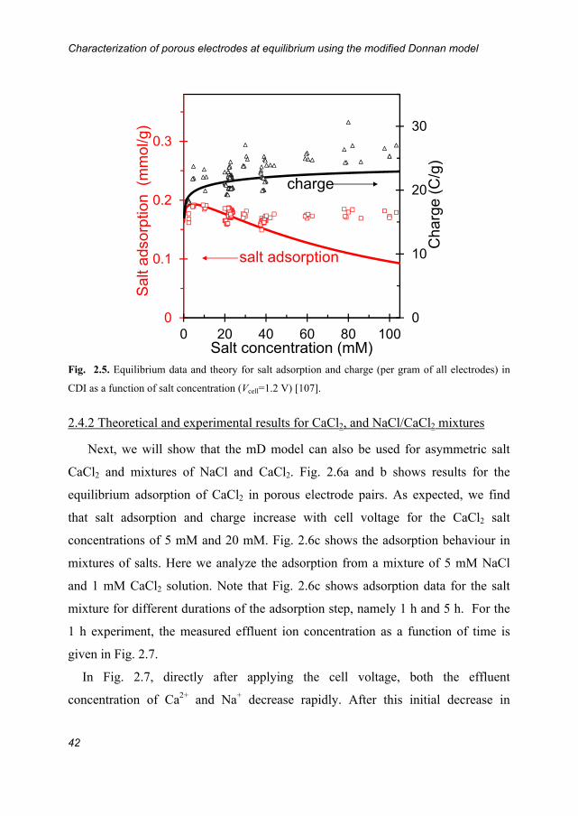
low ionic strength. To exemplify, a much broader spectrum of NaCl salt
concentration ranging from 0 to 100 mM was made both experimentally and
theoretically, which suggests that the equilibrium charge goes up with the increase
of salt concentration (Fig. 2.5). At the same time for salt, the salt adsorption only
increases at the very beginning of the salt concentration spectrum (~ from 2.5 mM
to 5 mM), and then it decreases in the salt concentration range of 5 mM to 40 mM,
afterwards it levels off. The difference between theory and experimental data in Fig.
2.5 demonstrates that further modification is necessary, e.g. by making µatt a
function of cj,mi (see section 6.2.3).
Characterization of porous electrodes at equilibrium using the modified Donnan model
42
Fig. 2.5. Equilibrium data and theory for salt adsorption and charge (per gram of all electrodes) in
CDI as a function of salt concentration (Vcell=1.2 V) [107].
2.4.2 Theoretical and experimental results for CaCl2, and NaCl/CaCl2 mixtures
Next, we will show that the mD model can also be used for asymmetric salt
CaCl2 and mixtures of NaCl and CaCl2. Fig. 2.6a and b shows results for the
equilibrium adsorption of CaCl2 in porous electrode pairs. As expected, we find
that salt adsorption and charge increase with cell voltage for the CaCl2 salt
concentrations of 5 mM and 20 mM. Fig. 2.6c shows the adsorption behaviour in
mixtures of salts. Here we analyze the adsorption from a mixture of 5 mM NaCl
and 1 mM CaCl2 solution. Note that Fig. 2.6c shows adsorption data for the salt
mixture for different durations of the adsorption step, namely 1 h and 5 h. For the
1 h experiment, the measured effluent ion concentration as a function of time is
given in Fig. 2.7.
In Fig. 2.7, directly after applying the cell voltage, both the effluent
concentration of Ca2+ and Na+ decrease rapidly. After this initial decrease in
0
10
20
30
0
0.1
0.2
0.3
0 20 40 60 80 100Salt concentration (mM)
Sal
t ads
orpt
ion
(m
mol
/g)
salt adsorption
charge
Cha
rge
(C/g
)
Chapter 2
43
effluent concentration, the electrodes start to saturate gradually, leading to
increasing effluent concentrations, eventually converging back to their inlet values.
Remarkably, all this time, up to the end of the adsorption step, the Ca2+-
concentration remains clearly below its inlet concentration of 1 mM, whereas the
Na+-concentration increases to beyond its inlet concentration of 5 mM and stays
above it until the end of the adsorption step, a phenomenon also observed in ref.
[110]. This behaviour is not witnessed in any of the single salt experiments, neither
NaCl nor CaCl2. This is a clear signature of a replacement process, in which the
composition of the EDLs, initially predominantly containing Na+, is slowly
modified toward the final equilibrium composition which is dominated by Ca2+.
The fact that in the end more Ca2+ is adsorbed than Na+ is also evident from the
effluent concentration profile during the desorption step, starting at 1 hr in Fig. 2.7,
since the Ca2+-peak during desorption is ~40% larger than the Na+ release peak.
Thus, the data in Fig. 2.7 show that Na+ is first adsorbed into the EDLs in the
electrodes but after ~10 min is being replaced again by Ca2+, even though the cell
voltage is still applied.
Contrary to the single-salt experiments described above, an experimental
duration of 1 h turned out to be insufficient to reach equilibrium (both ions’
concentrations did not converge to their initial values), so the adsorption was
extended to 5 h, when the individual ion adsorptions reach values consistent with
the fitted equilibrium theory, see Fig. 2.6c. Because the 5 h adsorption step is very
long, the data were obtained by analysing the effluent samples during the
desorption step. We assume that after 5 h, we have reached adsorption levels that
are close to equilibrium. Fig. 2.6c shows that Ca2+ ions are preferably adsorbed by
the electrodes than the Na+ ions. This is because Ca2+ ion has a higher valence (+2)
than the Na+ ion (+1), although the influent concentration of Na+ ions is five time
that of the Ca2+ ions. Parameter settings of Fig. 2.6 are given in Appendix B. In Fig.
2.6, lines present results of the mD model, and as can be observed for mixtures we

Characterization of porous electrodes at equilibrium using the modified Donnan model
44
can fit the data relatively well, using the same parameter settings that also describe
data for pure CaCl2-solutions, which suggests that the mD model is a useful tool to
describe experimental data for the equilibrium structure of the EDL in porous
electrodes in contact with mixtures of salts.
Fig. 2.6. (a,b). Equilibrium ion adsorption and charge as a function of cell voltage Vcell in CaCl2
mixtures at two values of the CaCl2-concentration (diamonds: 5 mM; triangles: 20 mM) [111]. (c).
Individual excess cation adsorption by a pair of porous electrodes, as a function of Vcell, for one value
of the NaCl/CaCl2 mixing composition. Comparison of data (circles: Ca2+, squares: Na+) with
modified-Donnan EDL-theory (lines) [111]. Parameter settings in the model are given in Appendix B.
0
0.04
0.08
0.12
0 0.2 0.4 0.6 0.8 1 1.2
0
0.04
0.08
0.12
0
10
20
30
0 0.2 0.4 0.6 0.8 1 1.2
Ca,
Na
(mm
ol/g
)
Ca
(mm
ol/g
) F
(C/g
)
Vcell (V)Vcell (V)
(a)
(b)
(c)CaCl2
CaCl2
1 mM CaCl25 mM NaCl
5 mM
20 mM
20 mM5 mM
5 h
1 h
5 h
Ca2+
Na+

Chapter 2
45
0
1
2
3
4
5
6
7
Con
cent
ratio
n (m
M)
Ca2+
Na+
0 1800 3600 5400Time (s)
Fig. 2.7. Ion effluent concentration in a mixture of 5 mM NaCl and 1 mM CaCl2 during adsorption at
Vcell=1.2 V, and desorption after 1 hour at Vcell = 0 V [111]. Lines serve to guide the eyes. Crosses and
triangles represent two separate experiments.
Characterization of porous electrodes at equilibrium using the modified Donnan model
46
2.5 Conclusions
In conclusion, the charge efficiency of a cell of two oppositely positioned
porous electrodes can be determined from the total salt adsorption and electrode
charge as reached at equilibrium without a-priori knowledge of the microporosity
for ion storage. A data set for as a function of cell voltage and ionic strength can
be used to validate models of ion distribution within the electrical double layers
which form inside micropores of the porous electrodes. We find that the modified
Donnan model, in which the chemical attraction term µatt and the Stern layer
capacity CSt,vol are freely adjustable parameters, describes our present data well.
Based on the validated modified Donnan model, we can derive the microporosity
of each employed carbon electrode. Our analysis points out that apart from the
microporosity, the volumetric Stern layer capacity is an equally important
parameter to characterize (and optimize) the capacity of porous electrode for salt
storage. Furthermore, we have demonstrated that the mD model can also be used to
describe equilibrium salt adsorption and charge data for more complex electrolyte
conditions, such as CaCl2 and mixtures of NaCl and CaCl2.

Chapter 3
47
Chapter3Transporttheoryof(Membrane)CapacitiveDeionization
embrane capacitive deionization (MCDI), a modified version of capacitive
deionization, is a technology for water desalination based on applying an
electrical field between two oppositely placed porous electrodes. Ions are removed
from the water flowing through a channel in between the electrodes and are stored
inside the electrodes. Ion-exchange membranes are placed in front of the electrodes
allowing for counterion transfer from the channel into the electrode, while retaining
the co-ions inside the electrode structure. We set up an extended theory for (M)CDI
which includes the modified Donnan model (see Chapter 2) for describing the
electrical double layers (EDLs) formed inside the porous carbon particles
composing the porous electrodes, and the transport pathways in the electrode, i.e.,
the interparticle pore space. Because in MCDI the co-ions are inhibited from
leaving the electrode region, the interparticle porosity becomes available as a
reservoir to store salt, thereby increasing the total salt storage capacity of the
porous electrode. Another advantage of MCDI is that during ion desorption
(release) the voltage can be reversed. In that case the interparticle porosity can be
depleted of counterions, thereby increasing the salt uptake capacity and rate in the
next cycle. In this work, we compare both experimentally and theoretically
adsorption/desorption cycles of MCDI for desorption at zero voltage as well as for
desorption at reversed voltage, and compare with results for CDI.
M

Transport theory of (membrane) capacitive deionization
48
3.1 Introduction
In the previous chapter, capacitive deionization (CDI) is discussed and the
method to characterize porous carbon electrode properties by using the modified
Donnan (mD) model is presented. In this chapter, we will introduce membrane
capacitive deionization (MCDI), which is a modification of CDI by positioning
ion-exchange membranes (IEMs) in front of the electrodes (cation-exchange
membranes for the cathode, and anion-exchange membrane for the anode), see Fig.
3.1, and will incorporate the mD model in a transport process model in order to
understand and predict the (M)CDI process.
Fig. 3.1. Schematic view of (a) membrane capacitive deionization (MCDI), and (b)
modelling approach for an electrode consisting of porous carbon particles.
Governed by the cell voltage, cations present in the water flowing through the
spacer channel migrate through the cation-exchange membrane and are stored
inside the adjacent porous electrode; simultaneously, anions are stored in the
opposite electrode. In CDI, the ion-exchange membranes are left out. [107]
Both CDI and MCDI are electro-capacitive processes, implying that
electrochemistry does (ideally) not occur, with charge storage of a purely
capacitive nature, and thus the process being repeatable without energetic losses.
The size scale of our cells is typically of the order of 100-300 m thickness for
Chapter 3
49
each layer (which are spacers, membranes, electrodes, and current collectors),
making a complete cell typically of the order of 1 mm thickness. Therefore,
(M)CDI is an example of a “millifluidic" flow technology. In CDI, the electron
current that goes from anode to cathode during ion adsorption is reversed during
ion release, with ideally a perfect charge balance, as defined in Chapter 2. An
external power source charges the CDI cell during the ion adsorption-step, i.e.,
energy is required to transfer electrons from the anode to the cathode, while during
ion release (ion desorption) the electrons spontaneously flow in the reverse
direction. During this stage, the electron current can be used to partially charge
another CDI-cell during its ion adsorption step. In this way the overall energy
consumption of a desalination stack consisting of multiple cells, can be reduced. It
is the general aim to find operation schemes for CDI where the total energy use is
as close as possible to the thermodynamic minimum energy input for desalination,
which is for a 1:1 salt given by per volume of
dilute product (of salt concentration cd, while the inflow has a salt concentration cin,
and the concentrate cc), where =cin/cd and =cin/cc, an expression valid for ideal
thermodynamic conditions [11, 63].
The only previous theoretical model for MCDI [94] considers that the ions are
adsorbed in the EDLs which are formed inside the carbon particles where the
electrolyte contacts the carbon matrix, without considering a possible salt storage
in the interparticle pore space or transport pathways in the electrode (which we call
macropores as in ref. [24], with the pores inside the carbon called the micropores
[24, 99, 112]). However, co-ions expelled from the EDLs inside the particles will
end up in these macropores. Because of charge neutrality there, more counterions
can then be absorbed in the electrode as a whole. In the present work we will
include the macropores in the theoretical model, and show that we are able to
min in d
ln ln2
1 1G RT c c

Transport theory of (membrane) capacitive deionization
50
describe experimental data for CDI and MCDI. Thus, the novel theoretical model is
suitable for predictive purposes such as for system optimization.
The (M)CDI transport model describes how the ion current across the membrane
into the electrode leads to a simultaneous electron current to keep charge balance in
the electrode. The ion current is mainly due to counterion transport, but for non-
ideal membranes also has a contribution from co-ions going in the reverse direction.
Note that the counterions are the ions being attracted into the electrode during the
ion adsorption-step (with opposite charge sign to that of the electrode surface),
namely, cations are counterions in the cathode, and vice-versa anions in the anode.
The co-ions are the ions being depleted during the ion release-step from the EDLs
in the micropores. The electron current will be charge-balanced partially by
counterion adsorption from the interparticle pore space (macropores, where the
concentration of cations equals that of the anions) into the EDLs which are formed
inside the micropores, and partially by the desorption of co-ions from the EDLs.
After being expelled from the EDLs, these co-ions are largely retained by the
membrane and thus accumulate in the interparticle pore space, increasing the
concentration to values beyond that in the spacer channel. One may wonder how
co-ions can be present behind the membrane (within the electrode structure) in the
first place. The answer is that the membranes are slightly leaky to co-ions, and thus
after several cycles, whatever the initial salt concentration behind the membrane is,
a certain steady-state amount of co-ions can be found. In comparison, in CDI the
co-ions are released from the electrodes, and end up in the spacer channel. This
leads to a reduced charge efficiency of the system, i.e., per amount of transported
charge, a lower number of salt molecules is removed from the water [63, 113]. In
MCDI, because of charge neutrality in the macropores, this accumulation of co-
ions also leads to an accumulation of counterions. Thus, effectively, part of the
transported counterions (from the spacer channel through the membrane) is
adsorbed in the EDLs in the micropores, and part is stored in the macropores.

Chapter 3
51
Therefore, the macropores serve as an additional reservoir for ion storage, which
play an important role in increasing the salt adsorption efficiency of MCDI, an
effect which is absent in CDI because in CDI the salt concentration in the
macropores is lower during ion-removal (not higher) while upon reaching
equilibrium it becomes the same as the salt concentration outside the electrode, i.e.,
in the spacer channel, and thus the macropores have no salt storage capacity in CDI
[95, 96].
A further advantage of MCDI is that it is possible to operate at reversed voltage
during ion release. This is not possible in CDI (the technology without membranes)
because then the ions that are released from the one electrode are quickly adsorbed
in the other electrode, without releasing much salt into the effluent stream, i.e., the
role of cathode and anode is simply reversed. In MCDI, the counterions are
released from one electrode into the spacer channel, but cannot move into the other
electrode because of the membrane. Thus both electrodes are depleted of their
respective counterions. Not only are counterions removed to the point that the
electrode is charge neutral again, but counterion desorption continues, first of all
from the EDLs in the micropores, in which now the co-ions are attracted as counter
charge, and secondly from the interparticle macropores, of which the salt
concentration drops dramatically. Thus we have a very effective clean-up of the
counterions from the electrode structure. Consequently, in the subsequent
adsorption step of the next cycle, the counterion adsorption rate and capacity can
be significantly increased [60, 94, 107].
In the next sections we will introduce the various theoretical elements of the
MCDI-model which includes the above effects, list the various assumptions,
present the mathematical framework to calculate desalination performance and
electrical currents, and compare model predictions with experimental data for CDI
and for MCDI in two operating modes: both for ion release at zero voltage
(“0-MCDI”), and for ion release at reversed voltage (“r-MCDI”).

Transport theory of (membrane) capacitive deionization
52
3.2 General discussion of theory for CDI and MCDI
In this section we introduce the elements of the theoretical process model which
can be used both for MCDI and CDI. We will describe the modifications relative to
previous theories in the literature, and list the various assumptions that are made.
As discussed in the previous section, the theory distinguishes between the
interparticle pores (the macropores in between the carbon particles) where
ccation=canion, and the micropores inside the carbon particles, where the concentration
of the cations and anions can be different, i.e., EDLs are formed [24, 99, 100, 112].
The pore volume inside the carbon particles (intraparticle porosity), we call the
microporosity, pmi, while the pores outside, i.e., in between, the carbon particles is
the interparticle, or macro-porosity, pmA. Formally, micropores and macropores are
defined as those pores with sizes <2nm and >50 nm, respectively, but we follow
literature on porous electrode transport theory [24] where microporosity is used for
the pores inside the carbon particles, and macroporosity for the much larger,
transport, pores, outside the carbon particle.
Transport of ions through the ion-exchange membrane in front of the electrode
will be described using the Nernst-Planck equation allowing for both types of ions
to permeate the membrane [114, 115]. Thus, the membranes are not considered to
be ideally permselective as in [94]. We will exclude transport of protons or
hydroxyl-ions and also set a possible water flow through the membrane to zero.
At the membrane-solution edges Donnan-equilibrium is assumed which relates
the ion concentration difference across each of these edges to the voltage drop
(Donnan potential).
Transport in the spacer channel is described in the flow direction (y) by
considering several ideal-stirred volumes placed in series. Each stirred-volume is
defined by a single salt concentration, i.e., we neglect a salt concentration gradient
in the direction of the membrane. This is different from the approach in ref. [94]
Chapter 3
53
where we made use of the concept of an equilibrium Nernst layer (stagnant
boundary layer, diffusion film, mass transfer layer, concentration-polarization
layer), a thin theoretical layer envisioned in front of the membrane, separating the
membrane from the spacer channel bulk volume, see refs. [94, 96, 116, 117].
Actually, this approach is problematic in MCDI because the spacer channel is
already quite thin, and thus a theoretical separation of the channel into a bulk-phase
and two diffusion films, is not well possible (actually, the spacer thickness is of the
order of a typical thickness of such a diffusion film, about 200 m). Furthermore,
full calculations using the Nernst-Planck equation showed that because our spacer
channel is thin, and because a significant part of the ion transport resistance is
located within the electrode, concentration variations across the spacer channel (in
x-direction) are not that significant. Note that this is different in electrodialysis
where mass transfer resistances are mainly in the flow channel.[12] Thus, across
the thickness of the spacer channel in x-direction we consider a constant salt
concentration (which depends on time, and on y-position) and thus we arrive at an
expression for the ion current J in x-direction which is proportional to the spacer
salt concentration, csp.
Within the porous electrode we do not use the full nonlinear porous electrode
theory for desalination described in refs. [95] and [96], but use a simplified
approach in which we average the concentrations across the electrode region (i.e.,
neglect salt concentration and potential gradients in the macropores), as in ref.
[118], and describe the transport resistance empirically by considering an electrical
resistance which is linearly dependent on the macropore salt concentration, cmA,
analogous to the description of the resistance in the spacer channel.
Additionally, for the electrode region we include the possibility that there is a
small convective leakage flow of solution through the electrodes, on the “wrong
side” of the membrane, entering the electrode “head-on”.
Transport theory of (membrane) capacitive deionization
54
To describe the EDL adsorption properties in the carbon particles, we use the
modified Donnan model, explained in Chapter 2, and define the salt adsorption and
charge as a concentration per unit volume of intraparticle pore space (i.e., based on
the micropore volume within the carbon particles). Assuming perfect symmetry of
the two electrodes, we can then derive the concentration of counterions and co-ions
in the micropores (relative to that at zero applied cell voltage) from measured salt
adsorption and charge in a CDI-cell, see Fig. 2.4b.
In this thesis we assume perfect symmetry in the cell: the membranes are either
in front of both electrodes, or in front of neither electrode (which is CDI). Both
membranes are assumed to have the same ion mobility and to have the same
membrane fixed charge density, X. Note that experimentally it is certainly possible
to place an IEM only in front of one membrane, and have water desalination, as
reported in ref. [60]. Furthermore we assume an equal mass of the anode and
cathode, and a symmetrical structure of the EDL, i.e., the EDL-structure in the
anode is completely similar to that in the cathode (except for the difference in
charge sign). We take the same diffusion coefficient for both ions, both in solution
(the spacer channel) and in the membrane.
We do not consider a possible role of protons and hydroxyl ions in determining
the structure of the EDL, e.g. by modifying the chemical surface charge of the
carbon. We only consider a monovalent 1:1 salt solution of ions that are fully
dissociated, like NaCl. We neglect possible Faradaic, electrochemical, reactions in
the electrodes.
3.3 Mathematical description of theory
In this section we present the mathematical model for the MCDI and CDI process,
based on the elements and assumptions explained in the previous section. We start
with discussing ion transport in the spacer, then the membrane, and finally describe
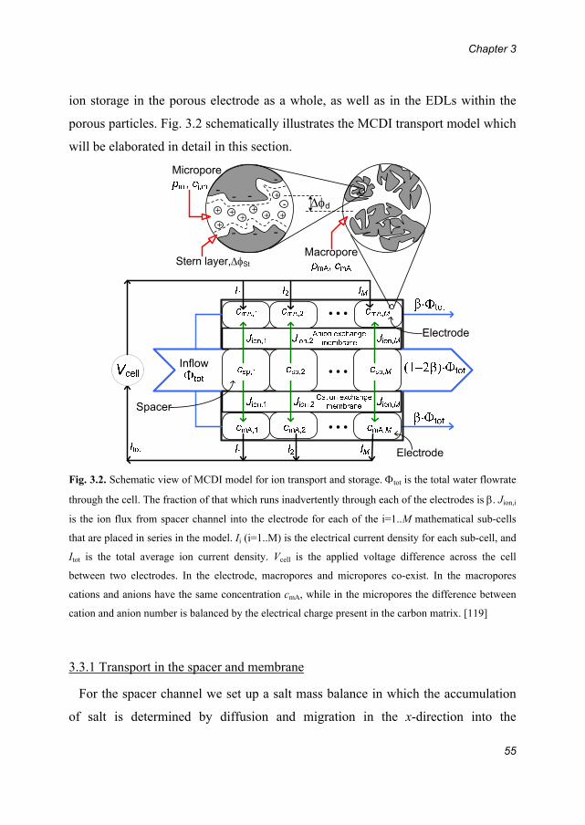
Chapter 3
55
ion storage in the porous electrode as a whole, as well as in the EDLs within the
porous particles. Fig. 3.2 schematically illustrates the MCDI transport model which
will be elaborated in detail in this section.
Fig. 3.2. Schematic view of MCDI model for ion transport and storage. tot is the total water flowrate
through the cell. The fraction of that which runs inadvertently through each of the electrodes is . Jion,i
is the ion flux from spacer channel into the electrode for each of the i=1..M mathematical sub-cells
that are placed in series in the model. Ii (i=1..M) is the electrical current density for each sub-cell, and
Itot is the total average ion current density. Vcell is the applied voltage difference across the cell
between two electrodes. In the electrode, macropores and micropores co-exist. In the macropores
cations and anions have the same concentration cmA, while in the micropores the difference between
cation and anion number is balanced by the electrical charge present in the carbon matrix. [119]
3.3.1 Transport in the spacer and membrane
For the spacer channel we set up a salt mass balance in which the accumulation
of salt is determined by diffusion and migration in the x-direction into the
+ ++
++
-
+
+
+
- -
- -
- - -
Stern layer,St
d

Transport theory of (membrane) capacitive deionization
56
membrane (or for CDI directly into the electrode), and by convective flow in the
axial, or y-, direction through the spacer channel, given by
(3.1)
where csp is the spacer salt concentration in mol/m3 (mM), t is time, Jion the ion flux
in x-direction at one interface directed into the membrane or electrode (in a
perfectly symmetric cell Jion is the same in magnitude on each interface, and thus
equal to the salt flux from the transport channel; note that we consider a 1:1 salt
thus two ions constitute one salt molecule), vsp the spacer water velocity, and y the
coordinate along the length of the channel from y=0 at the entrance to y=L at the
exit of the channel.
In using Eq. 3.1, we make several assumptions: 1. we neglect axial diffusion, or
dispersion in the y-direction, and 2. we consider concentration gradients in the x-
direction to be small. Both these assumption become the more valid the more the
cell length L exceeds the channel width, sp, a condition typically well met in an
(M)CDI flow-cell (e.g. 5 cm for L vs. 200 m for sp). The velocity, vsp, is given by
vsp=sp·L/Vsp, where sp is the water flowrate through the spacer channel
(volume/time), is the length (in y-direction) of the channel and Vsp is the spacer
channel volume.
The ion current density I in x-direction (flux of cations minus flux of anions) is
invariant with x (also constant across the solution/membrane interfaces, and across
the membrane; but it does depend on y). In the spacer channel, assuming absence
of concentration gradients in x-direction, and for equal ion diffusion coefficients,
the current I depends on the electrical potential difference across the spacer channel
half-space (from midplane to edge), sp,half, according to ref. [12]
, (3.2)
sp spionsp
sp
c y c yJ yv
t y
sp,half
sp2y
I y D c yh

Chapter 3
57
where is nondimensional and can be multiplied by the thermal voltage, VT=RT/F
(~25.7 mV), to arrive at a voltage with dimension Volt, and where h=sp/2. Current
I has dimension of moles/area/time, and can be multiplied by Faraday’s number, F,
and integrated over the membrane area A to obtain a total cell current with
dimension Ampère. The diffusion coefficient D is taken as the average of that of
the anion and the cation [12].
At the two membrane/solution interfaces we have Donnan equilibrium, both at
the edge of the membrane with the spacer channel, and at the edge of the
membrane with the electrode. These two Donnan potentials are given by [120, 121],
, (3.3)
where csalt is the salt concentration just outside the membrane (being either csp, or
the macropore salt concentration in the electrode, cmA), X is the membrane ‘ion
exchange capacity’, i.e., the magnitude of the membrane fixed charge density, and
is the sign of the membrane charge (e.g., =+1 for an anion-exchange
membrane).
Inside the membrane, charge balance is given by ccation-canion+X=0 which can be
combined with the Nernst-Planck (NP) equation for each ion, and the resulting set
of equations can be solved exactly [12, 115]. However, because full calculations
showed that the concentration and potential profiles across the membrane are close
to linear in a highly charged membrane, we linearize the NP-equations leading for
current I to
, (3.4)
where subscript “mem” is used for properties within the membrane, where cT,mem is
the total ion concentration in the membrane, given by cT,mem=ccation,mem+canion,mem,
where <..> denotes an average property, where is the difference across the
1donnan
salt
sinh2
X
c
memT,mem mem
mem
DI y c y y
Transport theory of (membrane) capacitive deionization
58
membrane, and where mem is the membrane thickness. At both solution/membrane
edges, the total ion concentration in
the membrane, cT,mem, is given by , with csalt as for Eq. 3.3 either csp or cmA. The
average concentration <cT,mem> required in Eq. 3.4 is calculated as the average of
these two boundary values for cT,mem. Likewise, the linearized total ion flux through
the membrane, Jion,mem, is given by
. (3.5)
In this linearized membrane-model we assume that the ion flux is constant across
the membrane and there is no accumulation of salt in the membrane. Full
calculations, however, based on the full NP-equation for the membrane,
implemented in a differential mass balance, show that this is not exactly true, and
that there can be differences in Jion,mem across the membrane (especially upon
voltage reversal in r-MCDI), leading to salt storage or depletion of the membrane
itself. This model extension, however, is not further considered in the present work.
For the linearized model, the ion flux through the membrane Jion,mem, is equal to
the ion fluxes in solution at the two solution/membrane edges. On the side of the
spacer channel, Jion,mem goes directly into Eq. 3.1, while on the side of the electrode,
it enters in the electrode ion balance, Eq. 3.10. The current density in the
membrane, I, given by Eq. 3.4, equals the current density in the spacer channel,
given by Eq. 3.2, and is equal to the current that runs into the micropores within the
electrode, see Eq. 3.9. These are the boundary conditions which apply in the
x-direction. In the axial y-direction, we only have to prescribe the inflowing
concentration csp(y=0)=cin.
We solve Eq. 3.1 by discretization into M ideally-stirred volumes placed in series,
like in ref. [94]. In that case, Eq. 3.1 can be simplified to:
22donnan c c X c2
T,mem salt salt= 2 cosh =
memion,mem T,mem mem
mem
DJ y c y X y
Chapter 3
59
. (3.6)
where i is a counter running from 1 for the first volume to M, the last, and is the
spacer channel residence time (spacer channel volume Vsp=Asp, divided by the
water flowrate sp). The inflow salt concentration into the cell is cin=csp,0 and the
effluent or outflow salt concentration is ceff=csp,M. All of the following equations in
this section are solved for each stirred volume (1<i<M) separately.
Finally, we consider the voltage across the cell which is given by the sum of the
potential drop over each spacer channel half-space (from 0 to h), sp,half, the
Donnan potential, donnan, at the membrane/spacer edge, the potential across the
membrane, mem, minus donnan at the membrane/electrode edge, the potential
drop in the electrode, elec, and the Donnan potential and the Stern layer potential
in the micropores, d+St. Those contributions together sum up to half of Vcell/VT,
where Vcell is the cell voltage, i.e. the voltage applied between the two electrodes,
Vcell=Vanode-Vcathode. This can be summarized as
(3.7)
where the electrode potential drop, elec relates to current density I according to
(3.8)
with Relec an electrode specific resistance with dimension .mol/m.
The above model can be used both for MCDI and for CDI. For CDI, the
membrane is absent, which can be modelled simply by setting the membrane
thickness mem and the membrane charge X to zero. In CDI this means that the
concentration in the spacer channel at the edge with the (now vanished) membrane
becomes equal to the concentration in the electrode macropores, cmA. Moreover,
exclusively for experiments in Fig. 3.4, the water is pumped from opening “2” (Fig.
sp,i ion,isp,i sp,i-1
sp sp
c J Mc c
t
dd
1cell T sp,half donnan,membrane/spacer mem2
donnan,membrane/electrode elec d St micropores
/
V V
elec T elec mA/ V I F R c

Transport theory of (membrane) capacitive deionization
60
2.2) into the stack, and is collected from opening “1” (Fig. 2.2), which causes
mixing of desalinated water and water in the “dead volume” of the stack. To
simulate this phenomena, the effluent salt concentration at opening “1”, ceff, can be
related to the water flowrate per stack Φ, the dead volume Vdead, and the
concentration at the M sub-cell csp,M, according to . This
modification is not necessary for any of the other experiments discussed in this
thesis, where the flow direction is towards opening “2” (Fig. 2.2).
3.3.2 Electrodes and electrical double layers
Within the electrodes, we do not consider in the x-direction any gradients in
potential, , and concentration, c, but take an average value for and c. Detailed
theory to describe ion migration and diffusion across a porous electrode, and thus
the resulting gradients in and c, is given in refs [95, 96, 122]. In the electrode,
there are two different porous (electrolyte-filled) phases. First of all, there are the
macropores, where we assume ccation=canion, which equals the macropore salt
concentration, given by cmA. This is the volume in between the carbon particles,
and has porosity pmA. Secondly, we consider the micropores with porosity pmi, in
which the cat- and anion concentrations, ci,mi, can be different from one another,
which we can determine using the modified Donnan model as is explained in
Chapter 2. The porosities pmA and pmi are defined as pore volumes per unit total
electrode volume, with the macropore salt concentration cmA defined per unit
macropore volume, and the ion concentrations in the micropores, ci,mi, defined per
unit of micropore volume.
The first electrode balance describes how the “charge concentration” in the
micropores, ccharge,mi=ccation,mi-canion,mi , relates to the current density I (defined on the
projected area of the electrode, A) according to
d( )
d
c c c
t Veff sp,M effdead

Chapter 3
61
, (3.9)
where elec is the electrode thickness.
The second electrode balance relates the membrane ion flux, Jion, to the total ion
concentration in the electrode,
, (3.10)
where elec is the superficial residence time in the electrode due to convective flow
of solution through the electrode. The residence time elec is given by the total
electrode volume Velec divided by the electrode flowrate elec. This leakage flow of
water is calculated as follows. The total water flowrate per cell is tot, and the
fraction of that which runs through an electrode is elec=tot, and thus the flow
directed through the spacer channel is sp=(1-2)tot. The flows through the
spacer channel and through the two electrodes are combined into the effluent which
leaves the cell, and of this mixture the salt concentration, ceff, is given theoretically
by ceff=(1-2)csp,M+2cmA,M, see Fig. 3.2.
To model the structure of the EDLs in the electrodes, we employ the
“modified Donnan model”, as described in Chapter 2. The concentration of a
specific ion cj,mi in the micropore volume related to the macropore salt
concentration cmA is given by Eq. 2.4 in Chapter 2. Moreover, micropore charge
concentration ccharge,mi relates to the Stern layer potential drop ∆st, according to Eq.
2.6. This finalizes the cell model as will be used both for CDI and MCDI, both
with ion release at zero voltage (0-MCDI) and for ion release at reversed voltage
(r-MCDI).
imi charge,mi,i
elec
d
d
Ip c
t
ion,imA mA,i mi cation,mi,i anion,mi,i mA,i mA,i-1
elec elec
d2
d
J M
p c p c c c ct

Transport theory of (membrane) capacitive deionization
62
3.4 Experimental setup and parameter settings for transport
modelling of (M)CDI
Experimental details of our CDI test stack have been described in Chapter 2 (also
see Fig. 2.2). To construct an MCDI stack, the modification we implement is
inserting a cation-exchange membrane between the cathode and the spacer channel
and an anion-exchange membrane between the anode and the spacer channel. In
brief, N=8 cells as depicted in Fig. 3.1 are assembled from current collectors,
electrodes, ion-exchange membranes and spacers. Each current collector is used in
two adjacent cells (one above, and one below). Therefore, for MCDI it is important
to reverse the sequence of ion-exchange membranes from cell to cell because the
cathode and anode positions are also reversed. The salt solution flows from outside
the stack on all four sides into the square 6x6 cm2 spacer channel of each of the N
cells, and leaves from a hole in the middle of each cell (area 1.5x1.5 cm2), or the
reverse (only for experiments in Fig. 3.4). These are the dimensions of all layers.
Thus, the projected area A per electrode (membrane) is given by A=33.8 cm2.
Materials used are graphite current collectors as described in section 2.2, porous
carbon electrodes (the electrode properties are given in Appendix B). Besides, we
use anion and cation-exchange membranes (Neosepta AMX, mem=140 m, and
Neosepta CMX, mem=170 m, Tokuyama, Japan), and a polymer spacer (Glass
fibre prefilter, Millipore, Ireland, sp=250 m), see Fig. 3.3. After assembly, the
entire stack of all layers is firmly pressed together and placed in a Teflon (PTFE)
housing.

Chapter 3
63
Fig. 3.3. Photograph of the sequenced components of one MCDI cell, from left to right: (1) graphite
current collector, (2) porous carbon electrode, (3) anion exchange membrane, (4) glass fibre spacer, (5)
cation exchange membrane, (6) porous carbon electrode, and (7) graphite current collector.
As described in Chapter 2 already, the conductivity of the effluent salt
concentration of the stack, in this chapter only NaCl, and the effluent pH are
measured on-line, and together are converted into the net salt concentration
according to a calibration curve. For all experiments in section 3.5.2, the water
flowrate per stack is fixed at 60 mL/sec. Since we have 8 cells in one stack, per
cell the water flowrate tot is equal to 0.125 mL/sec. The cell voltage is applied
using a potentiostat which measures the current between cathode and anode after
applying a step change in cell voltage. To get the total charge with dimension
Coulomb in Fig. 3.5, the current is integrated for the duration of the ion adsorption
step, given that the total charge transferred is equal (within measurement error and
for a small leakage current) to the charge released again in the ion-release step. The
effluent salt concentration is calculated from the measured conductivity, and the
salt removal per total electrode mass, salt, is derived from the first equality in
Eq. 3.11 below. To calculate salt removal in the theoretical model, we use two

Transport theory of (membrane) capacitive deionization
64
methods: 1. Integration over time of the difference between the effluent
concentration ceff and the inflowing concentration cin, times the total water flowrate,
tot, like we do for the analysis of the data, or 2. Taking the difference in total salt
storage in the cells between time t1 and t2, mathematically, these two methods are
expressed as:
, (3.11)
where t1 denotes the moment that the cell voltage undergoes a step change, t2
denotes the end of the step starting from t1.
In section 3.5.2, when the applied desorption time is not long enough for all the
ions adsorbed in the porous electrode during the ion adsorption step to be released
again, the ions retained in the electrode region will reduce the salt adsorption
capacity in the next ion adsorption step. Therefore, we have to run several (M)CDI
cycles in a row, both experimentally and theoretically, in order to reach the
‘dynamic equilibrium’ (DE), where the measured salt adsorption during one phase
of the cycle is equal to the salt desorption in the other phase of the cycle (salt
balance is maintained). Likewise, the total charge transferred in one direction (from
cathode to anode) during the salt adsorption step, is close to the charge transfer
directed in the opposite direction during the salt release-step. Note that all results
shown in this chapter are obtained under the DE condition.
To calculate the voltage drop across the spacer channel we take the average of
the diffusion coefficients [12] of Na+ and Cl-, resulting in 1.6810-9 m2/s. For the
diffusion coefficient in the membrane we arbitrarily take 10% of the value of
solution, thus Dmem=1.6810-10 m2/s. For the spacer and membrane thickness we
take sp=250 m and mem=140 m, while we use a membrane fixed charge density
2
1
2
1
spsalt eff in
tot
1sp sp,i elec mA mA mi cation,mi anion,mi2
1tot
d
2
M
i
t
t
t
t
Nc c t
m
NAc p c p c c
m M

Chapter 3
65
of X=8 M. In the calculation, the number of stirred volumes placed in series, M, is
set to M=6. Values of input parameters for section 3.5.1 and 3.5.2 are summarized
in Appendix B. For some parameters, values slightly differ between the two
sections. This is because of different batches of electrode material used.
3.5 Results and discussion
3.5.1 Comparison of experimental results and theory for CDI
In this section, we present the reproduction of the CDI process by the theory. Fig.
3.4 compares calculations with experimental data for effluent salt concentration
and electrical current. All calculations are based on a single set of input parameters
listed in Appendix B, both for ion adsorption and for ion release. To begin with, we
fix the water flowrate at 60 mL/min, and the influent salt concentration at 5 mM,
and vary the applied cell voltage. Panels a and c show experimentally the effluent
salt concentration and the electrical current as a function of time, indicating that a
higher cell voltage leads to higher salt adsorption per cycle and also higher charge
transferred. Panels b and d are theoretical results which reproduce the experimental
ones very well. Since the equilibrium is reached (the effluent salt concentration is
at its initial value at the end of the adsorption/desorption step, and the electrical
current converges to zero), charge efficiency Λ can be derived by taking the ratio
of salt adsorption to total charge. The results of total salt adsorption, total charge
and charge efficiency are shown in Fig. 2.4, Chapter 2. In Fig. 3.4, panels e and f
are experimental and theoretical results for different water flowrates, while the
influent salt concentration and the cell voltage are fixed. By varying the water
flowrate, although at lower water flowrate, ‘fresher’ water can be produced (the
effluent salt concentration is lower), the total salt adsorption remains the same.
This is because when calculating the total salt adsorption, not only we have to

Transport theory of (membrane) capacitive deionization
66
integrate the effluent salt concentration relative to the influent concentration (ceff-cin)
over time, the water flowrate also need to be taken into account, see Eq. 3.11. In
the end, we show the effluent salt concentration as a function of time for three
influent salt concentrations (5, 10 and 20 mM) both experimentally (panel g) and
theoretically (panel h). The total salt adsorption for those concentrations can also
be derived based on the method given by Eq. 3.11, and the results can be found in
Fig. 2.4, Chapter 2. To conclude, CDI process without ion-exchange membrane can
be extrapolated by our (M)CDI process model on the basis of certain reasonable
assumptions made in the model (X=0, δmem=0).

Chapter 3
67
Fig. 3.4. CDI process data (left column) and theory (right column) as a function of cell voltage Vcell
(a-d), flowrate (e-f) and ionic strength of inlet solution c0 (g-h). At time zero a positive cell voltage
is applied, which is reduced to zero halfway the cycle. [106]

Transport theory of (membrane) capacitive deionization
68
3.5.2 Comparison of theory with experiments for salt adsorption and charge in CDI
and MCDI as a function of cycle time
In this section we discuss data where we accurately compare CDI with 0-MCDI
(MCDI with ion release at zero cell voltage) and with r-MCDI (where ion release
occurs at reversed voltage). Experimentally, CDI and 0-MCDI were previously
compared by Kim and Choi, in ref. [60] for Vcell=1.2 V and csalt=3.5 mM, in ref.
[123] for Vcell=1.5 V and csalt=3.5 mM, and in ref. [124] for Vcell=1.2-1.6 V and
csalt=17 mM. In all cases the half-cycle time to be defined below, was HCT=180 s.
In refs. [60] and [123] only a cation-exchange membrane was placed in front of the
cathode (without a membrane placed in front of the anode), while in ref. [124] both
cation-exchange and anion-exchange membranes were used, in front of cathode
and anode, respectively (just as in the present work). When going from CDI to 0-
MCDI, the reported increase in salt removal per cycle was about 30% in ref.[60],
about 20% in ref. [123], but was much higher in ref. [124] where the salt
adsorption per cycle was reported to increase by at least 100% (see Fig. 2 of ref.
[124]). This large increase may be related to the low current efficiency reported for
CDI there (i.e., CDI-performance may not have been optimal in these experiments).
Theoretically, 0-MCDI and r-MCDI were previously only briefly compared in ref.
[94] (Fig. 5, Vcell=1.4 V, cNaCl=36 mM) showing a predicted ~20% increase in salt
removal for r-MCDI compared to 0-MCDI. In the present work, we compare CDI
with 0-MCDI and r-MCDI, both experimentally and theoretically. This will be
done on the basis of data for cNaCl,in=20 mM at a cell voltage of Vcell=1.2 V and a
flowrate of tot=0.125 mL/s per cell. The data are presented as a function of the
‘half-cycle time’, HCT, i.e., the duration of an ion adsorption-step, which is set
equal to the duration of the subsequent ion-release step. Thus, the full cycle time is
twice the HCT. For application of (M)CDI in practice, it is important that HCT is
optimized to maximize the average salt removal rate, see Chapter 5.
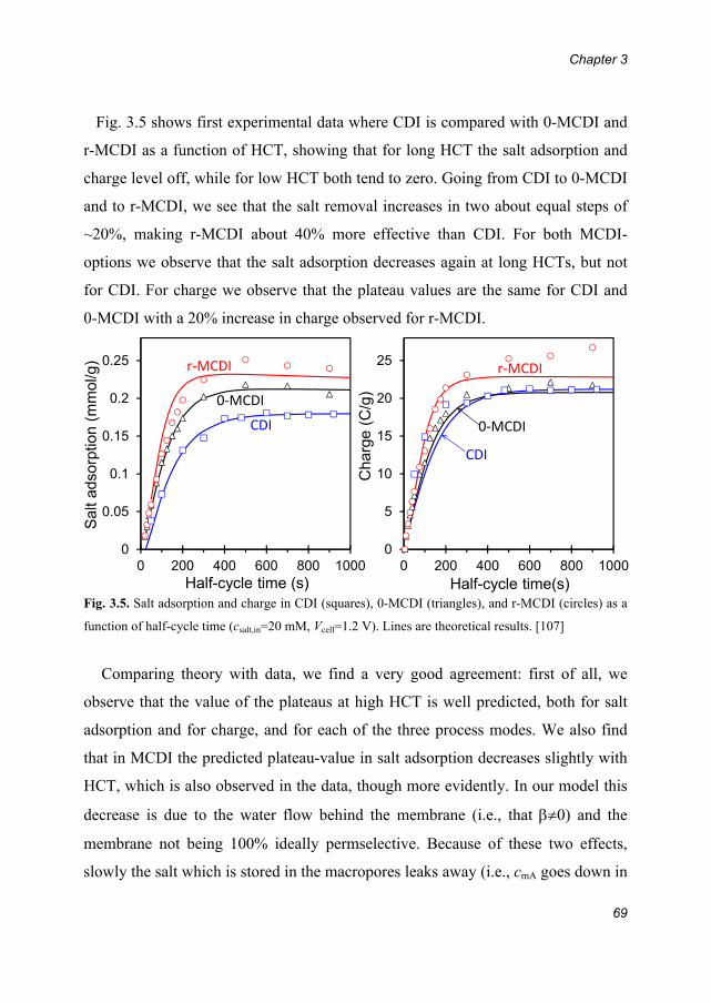
Chapter 3
69
Fig. 3.5 shows first experimental data where CDI is compared with 0-MCDI and
r-MCDI as a function of HCT, showing that for long HCT the salt adsorption and
charge level off, while for low HCT both tend to zero. Going from CDI to 0-MCDI
and to r-MCDI, we see that the salt removal increases in two about equal steps of
~20%, making r-MCDI about 40% more effective than CDI. For both MCDI-
options we observe that the salt adsorption decreases again at long HCTs, but not
for CDI. For charge we observe that the plateau values are the same for CDI and
0-MCDI with a 20% increase in charge observed for r-MCDI.
Fig. 3.5. Salt adsorption and charge in CDI (squares), 0-MCDI (triangles), and r-MCDI (circles) as a
function of half-cycle time (csalt,in=20 mM, Vcell=1.2 V). Lines are theoretical results. [107]
Comparing theory with data, we find a very good agreement: first of all, we
observe that the value of the plateaus at high HCT is well predicted, both for salt
adsorption and for charge, and for each of the three process modes. We also find
that in MCDI the predicted plateau-value in salt adsorption decreases slightly with
HCT, which is also observed in the data, though more evidently. In our model this
decrease is due to the water flow behind the membrane (i.e., that 0) and the
membrane not being 100% ideally permselective. Because of these two effects,
slowly the salt which is stored in the macropores leaks away (i.e., cmA goes down in
0
0.05
0.1
0.15
0.2
0.25
0 200 400 600 800 1000
Sal
t ad
sorp
tion
(mm
ol/g
)
Half-cycle time (s)
0
5
10
15
20
25
0 200 400 600 800 1000Half-cycle time(s)
Cha
rge
(C/g
)r‐MCDI
0‐MCDI
CDI
r‐MCDI
0‐MCDI
CDI

Transport theory of (membrane) capacitive deionization
70
time). The decline in salt adsorption and charge when HCT goes to zero is also
well reproduced for all three process options.
Fig. 3.6 shows experimental data and theoretical predictions for the effluent
concentration as a function of time, for one value of the half-cycle time, namely
HCT=300 s. As can be observed the predicted curves are quite similar to the
experimental ones, certainly for CDI and 0-MCDI. For r-MCDI the minimum in
effluent salt concentration occurs later in theory than in the experiment, and is
deeper, while the maximum (upon voltage reversal) is much higher, and the decline
in ceff is more rapid than experimentally.
Fig. 3.6. Comparison of experimental data and theoretical model for CDI, 0-MCDI, and r-MCDI, for
a half-cycle time of 300 sec (csalt,in=20 mM, Vcell=1.2 V). [107]
Finally, Fig. 3.7 shows the predicted development of the macropore
concentration, cmA, as a function of time, showing the very marked differences
between CDI, 0-MCDI and r-MCDI. For both MCDI-options, the macropore
concentration, cmA, goes up during ion adsorption while it goes down for CDI,
explaining the higher ion adsorption capacity for MCDI vs CDI.
In conclusion, in this work we have made significant progress in setting up a
comprehensive model which can describe both CDI and MCDI, with ion release at
0
10
20
30
40
50
60
70
0 100 200 300 400 500 600
Time (s)
Effl
uent
sal
t con
cent
ratio
n (m
M)
r-MCDI
0-MCDI
CDI
r-MCDI
0-MCDI
CDI
0
10
20
30
40
50
60
70
0 100 200 300 400 500 600
Time (s)
Effl
uent
sal
t con
cent
ratio
n (m
M)
a
r-MCDI
r-MCDI
0-MCDI
0-MCDI
CDI
CDI
DATA THEORY

Chapter 3
71
zero voltage as well as at reversed voltage. Important is consideration of the
macropore volume, where the cation concentration equals that of the anions, as
well as the use of the modified Donnan model for charge and salt storage in the
micropores within the carbon particles.
Fig. 3.7. Theoretical prediction for macropore salt concentration for CDI, 0-MCDI, and r-MCDI (4th
sub-cell out of the total of M=6), for conditions as in Fig. 3.6. [107]
0
10
20
30
40
0 100 200 300 400 500 600
Mac
ropo
re s
alt
conc
entr
atio
n (m
M)
a
Time (s)
r-MCDI
r-MCDI
0-MCDI
0-MCDICDI
CDI

Transport theory of (membrane) capacitive deionization
72
3.5 Conclusions
We have set up a comprehensive model which describes both capacitive
deionization (CDI) and membrane capacitive deionization (MCDI). For MCDI two
operation modes are considered, either “0-MCDI” where ions are release at zero
cell voltage, and “r-MCDI” where the ions are release at reversed voltage.
Experiments and modelling agree that 0-MCDI removes around 20% more salt
than CDI, and r-MCDI again 20% more. The model includes several novel
elements, such as including the fact that also co-ions can pass the ion-exchange
membrane, while for the electrode, a distinction is made between the transport
pathways, or macropores, where the concentration of both ions is the same, and the
micropores inside carbon particles where charge is stored and thus the ion
concentrations can be different. For the micropores a modified Donnan model is
implemented to describe equilibrium data for salt adsorption and charge. An ion
transport resistance in the electrode was included by considering a resistance which
is inversely proportional to the macropore salt concentration. Major trends in salt
adsorption and charge as a function of the duration of the (M)CDI-cycle are well
reproduced by the theory, as well as the profiles of effluent concentration vs. time.
The validated MCDI process model can be used for design and process
optimization studies.

Chapter 4
73
Chapter4EnergyConsumptionandConstantCurrentOperationinMembraneCapacitiveDeionization
embrane capacitive deionization (MCDI) is a water desalination
technology based on applying a cell voltage between two oppositely
placed porous electrodes sandwiching a spacer channel that transports the water to
be desalinated. The classical operational mode of MCDI at a constant cell voltage
results in an effluent stream of desalinated water of which the salt concentration
varies with time. In this chapter, we propose a different operational mode for
MCDI, whereby desalination is driven by a constant electrical current, which leads
to a constant salt concentration in the desalinated stream over extended periods of
time. Furthermore, we show how the salt concentration of the desalinated stream
can be accurately adjusted to a certain set point, by either varying the electrical
current level and/or the water flowrate. Finally, we present an extensive data set for
the energy requirements of MCDI, both for operation at constant voltage, and at
constant current, and in both cases also for the related technology in which
membranes are not included (CDI). We find consistently that in MCDI the energy
consumption per mole of salt removed is lower than in CDI. Within the range 10-
200 mM ionic strength of the water to be treated, we find for MCDI a constant
energy consumption of ~22 kT per ion removed. Results in this chapter are an
essential tool to evaluate the economic viability of MCDI for the treatment of
brackish water.
This chapter has been published as:
Zhao, R., Biesheuvel, P. M. & Van der Wal, A. Energy Consumption and Constant Current
Operation in Membrane Capacitive Deionization. Energy & Environmental Science 5, 9520-9527
(2012)
M

Energy consumption and constant current operation in membrane capacitive deionization
74
4.1 Introduction
A Membrane Capacitive Deionization (MCDI) cell is a modification of a
conventional CDI cell, which in addition contains anion and cation-exchange
membranes which are positioned between the spacer channel and the anode, and
between the spacer channel and the cathode, respectively [52, 58, 60, 107, 110,
124-127], see Fig. 3.1 in Chapter 3. It is also possible to use only one membrane, in
front of only one electrode [57, 60]. Because of the use of ion exchange
membranes MCDI has two major advantages over conventional CDI, which are
discussed in Chapter 3.
At present, it is common practice to control the desalination cycles of (M)CDI by
applying a constant cell voltage (the electrical potential difference between the two
porous electrodes) during charging (ion adsorption) as well as during discharging
(ion desorption) of the electrodes. For example, during ion adsorption, a typical
value of Vcell=1.2 V is applied to adsorb ions and produce fresh water, while during
discharge, the two electrodes can be short-circuited, i.e., the cell voltage is reduced
to 0 V. However, operation at a constant cell voltage has as a disadvantage that the
effluent salt concentration changes in time, i.e., the ion concentration in the
desalinated water stream (fresh water) changes during the ion removal step. This is
because at the start of the adsorption step, the EDLs are still mainly uncharged, and
thus the driving force over the channel is at a maximum (no loss of cell voltage in
the EDLs). Consequently, there is a large ion flux directed into the electrodes. As
ion adsorption in the EDLs progresses, the EDL voltage gradually increases and
the remaining voltage across the spacer channel steadily decreases in time. The
overall effect is that the effluent salt concentration will first decrease, go through a
minimum, and then gradually increase again. This gradual change of effluent
concentration over time may not be desired in practical applications; instead, it
may be more advantageous if water is produced of a constant desalination level.
Chapter 4
75
To obtain fresh water with a constant reduced salt concentration, we propose a
different mode to carry out the MCDI desalination cycles, namely by applying a
constant current (CC) running between the two electrodes, instead of using a
constant cell voltage (CV). The externally applied constant electron current, I,
translates into an equally large ionic current in the cell, which has contributions
from the ionic flux of positive ions (such as Na+) and negative ions (such as Cl-).
As we will show, in MCDI, operation with constant current results in an effluent
salt concentration which is constant in time, both during the ion adsorption step and
during the ion desorption-step. Another advantage of operation using constant
current is that the effluent concentration can be easily and accurately controlled at a
certain required value by varying the current level. This may be advantageous from
the viewpoint of the consumer who desires a supply of fresh water with constant
and tunable salt concentration.
Furthermore, we present an extensive data set for the energy requirement of
MCDI versus CDI, not only for the novel operational mode of CC, but also for the
classical CV-mode of operation. These data can be used to assess the economic
viability of the technology, as well as to validate process models; models which are
an essential tool for the design and optimization of CDI and MCDI. We show that
the energy requirement is closely linked to the dynamic charge efficiency, an
important operational parameter both in CDI and MCDI.
4.2 Experimental Section
4.2.1 Experimental setup
The experimental setup of our MCDI stack is described in Chapter 3, see
Appendix B for details. The salt adsorption and charge in an MCDI-cycle can be

Energy consumption and constant current operation in membrane capacitive deionization
76
derived from the data of salt effluent (outflow) concentration versus time, and
electric current versus time. For salt adsorption, the difference between inflow salt
concentration and outflow concentration is integrated with time, and multiplied
with the water flow rate, while for charge, the current is integrated with time. All
data shown in this chapter are obtained under the dynamic equilibrium (DE), where
both salt and charge balance are maintained, as explained in Chapter 3. In the
standard experiment we apply 1 A to the full stack of N=8 cells, which translates
to an average current density (per unit cell area) of 37 A/m2.
4.2.2 Energy requirements
To calculate the energy requirement for the removal of one ion, as presented in
Fig. 4.3, we take the ratio of energy consumption over desalination, both calculated
strictly based on the duration of the ion adsorption step. In the present work, the
adsorption step is defined to start and end at the exact moments that voltage or
current signals are changed, not by the moments that the effluent salt
concentrations drops below, or increases to beyond, the inlet salt concentration
(which is 20 mM in Figs. 4.1 and 4.2). For a discussion on alternative methods, see
section 6.3. Desalination is calculated from integration over time, during the ion
adsorption step, of the difference cin-ceffluent, and multiplying by water flow rate ,
and by the factor 2. The factor 2 is because we present data for the energy to
remove an ion, not to remove a salt molecule. The energy is calculated as cell
voltage Vcell times current I, integrated again over the duration of the ion adsorption
step. The ratio energy/desalination gives us the energy in J per mole of ions
removed. Dividing this number by a factor RT (=2.48 kJ/mol at room temperature)
results in the energy in units of “RT per mole of ions”, which has the same
numerical value as is expressed in “kT per ion” as in Fig 4.3a-c. We neglect energy
recovery during the ion release-step, see section 6.3.

Chapter 4
77
4.2.3 Dynamic charge efficiency
The dynamic charge efficiency, dyn, denotes the ratio of two properties: the total
desalination during ion adsorption (in moles), as described above, divided by total
charge transferred in the same period (charge with unit Coulomb must be divided
by Faraday’s constant, F, to obtain charge in moles). In the present work, the
parameter dyn is obtained during relatively short cycles in which the EDLs are not
allowed to come to equilibrium with the salt concentration in the spacer and inlet
flow. Thus, formally, we have not measured (nor do we theoretically model), the
equilibrium charge efficiency, , as defined in Chapter 2, which requires that the
system becomes equilibrated at set values of the cell voltage with the salt
concentration in the macropores the same as in the inlet stream. Thus, to describe
the measured ratio of desalination and charge, in the present work we use the
modified term, “dynamic charge efficiency.”
4.3 Theory
The theoretical model used to describe ion transport and storage in MCDI and
CDI is described in detail in Chapter 3. All calculations presented in Figs. 4.1-4.3
are based on a single set of parameter values, given in Appendix B. Note that in
most of the experiments presented here we do not apply a constant voltage, but we
apply a total current to the whole cell. In the model, this total (average) ion current
density, Itot, distributes self-consistently over the M sub-cells, thus is
solved for all M sub-cells simultaneously. In all sub-cells, the cell voltage is at each
moment in time the same throughout the electrode. In order to avoid numerical
problems for the CC operation, when applying a step change in current to the
MCDI cell, a small external capacitance was added in the circuit model, see in
Appendix C. Beyond this modification of the externally applied current-voltage
to t ii 1
1 M
I IM

Energy consumption and constant current operation in membrane capacitive deionization
78
characteristic, there is for the ions no fundamental difference between CV- or CC-
operation, in the sense that the forces acting on an ion to move into the pores and to
be stored there are fundamentally unchanged.
4.4 Results and Discussion
In this section we show results of MCDI operation using different operational
modes, focusing on the difference between constant voltage (CV) and constant
current (CC) operation. Results are presented of two modes of CC operation. For
these three modes in total, to be discussed below in detail, we show in Fig. 4.1
experimental and theoretical results for three main operational characteristics:
effluent concentration, cell voltage, and current, all as a function of time. In all
cases (also for Figs. 4.2 and 4.3), results are shown of a steady-state cycle, i.e., not
the first or second cycle from a new series, but a cycle which repeats itself almost
unchanged for a prolonged period. In all nine panels, data are presented as dashed
red lines, and predictions of the theoretical model of Chapter 3 are shown by solid
blue curves.
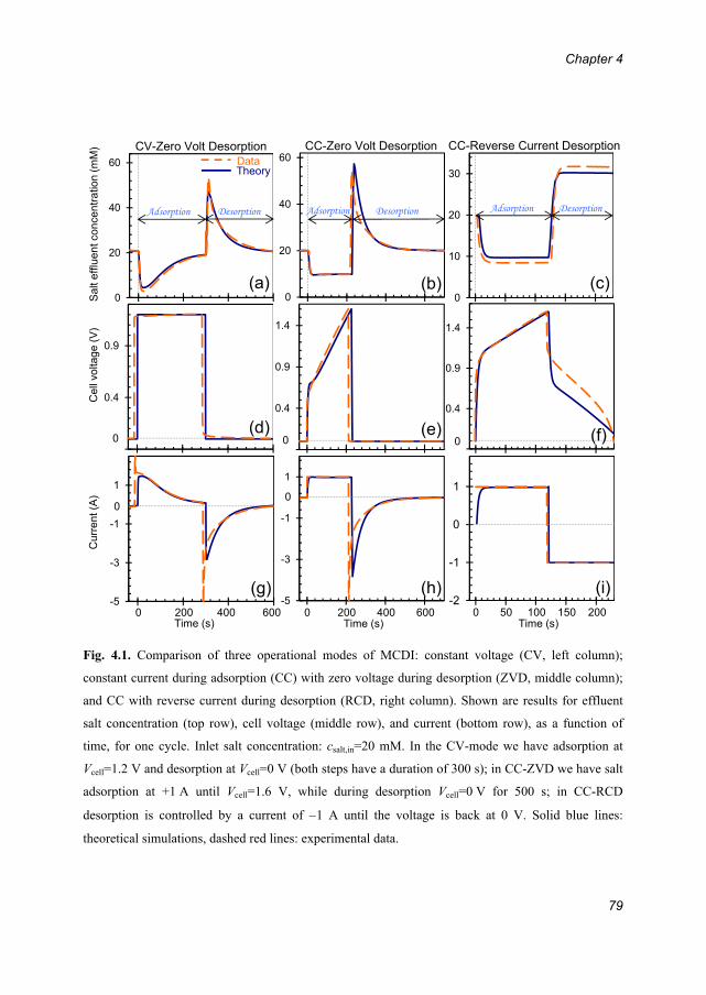
Chapter 4
79
Fig. 4.1. Comparison of three operational modes of MCDI: constant voltage (CV, left column);
constant current during adsorption (CC) with zero voltage during desorption (ZVD, middle column);
and CC with reverse current during desorption (RCD, right column). Shown are results for effluent
salt concentration (top row), cell voltage (middle row), and current (bottom row), as a function of
time, for one cycle. Inlet salt concentration: csalt,in=20 mM. In the CV-mode we have adsorption at
Vcell=1.2 V and desorption at Vcell=0 V (both steps have a duration of 300 s); in CC-ZVD we have salt
adsorption at +1 A until Vcell=1.6 V, while during desorption Vcell=0 V for 500 s; in CC-RCD
desorption is controlled by a current of 1 A until the voltage is back at 0 V. Solid blue lines:
theoretical simulations, dashed red lines: experimental data.
0
10
20
30
-0 1
0.4
0.9
1.4
-2
-1
0
1
0
20
40
60
-0 1
0.4
0.9
1.4
-5
-3
-1
1
0
20
40
60
-5
-3
-1
1
-0.1
0.4
0.9
CV-Zero Volt Desorption CC-Zero Volt Desorption CC-Reverse Current Desorption
TheoryData
Adsorption Desorption Adsorption Desorption Adsorption Desorption
Sa
lt e
fflu
en
t co
nce
ntr
atio
n (
mM
)C
ell
volta
ge
(V
)C
urr
en
t (A
)
Time (s) Time (s) Time (s)0 200 400 600 0 200 400 600 0 50 100 150 200
00
0 0 0
(a) (b) (c)
(f)(e)(d)
(g) (h) (i)

Energy consumption and constant current operation in membrane capacitive deionization
80
The three characteristics presented in Fig. 4.1 are: on the top row, first of all the
effluent concentration (the concentration of the fresh water during the first period,
denoted “adsorption” in panels a-c, and the concentration of the high-salinity
stream in the desorption step); second the cell voltage (middle row; either applied
or measured); and finally the electrical current (bottom row; either applied or
measured). The first vertical column shows results of classical operation at constant
voltage, as used in practically all previous work in the literature of CDI and MCDI.
In this case, operation is first for a predetermined duration (here 300 s) at a pre-set
value of the cell voltage, namely Vcell=1.2 V (see panel d) to desalinate the water,
followed by a stage of the same duration at zero cell voltage. The current (panel g)
is high at the start of each step and then decays back to zero. The salt effluent
concentration (panel a) shows the minimum during ion adsorption as discussed
previously, while during desorption we have a short peak in salt concentration
before the concentration slowly decays back to the inlet value.
In the second column we show results of applying constant current (CC)
conditions, but in this case CC is only applied during ion adsorption, while the ion
desorption step is still defined by applying a zero voltage (now for 500 s; CC-ZVD
mode). The CC-condition is applied until a pre-set upper voltage limit of Vcell=1.6
V is reached. At that moment we switch to the desorption step. Because of
operation at CC during ion adsorption, the cell voltage steadily increases, after an
initial rapid increase due to Ohmic resistances (panel e). Most importantly, we see
in panel b that the freshwater salt effluent concentration is now at a stable value
during the ion adsorption step (after a brief initial transition period), here around
cfreshwater=10 mM.
In the third, right, column we show results of CC operation where also during
desorption a constant current is applied, of equal magnitude but opposite in sign
compared to adsorption (see panel i; CC-RCD mode). Both steps are now defined
by limiting values of the cell voltage, being 1.6 V during adsorption and 0 V during
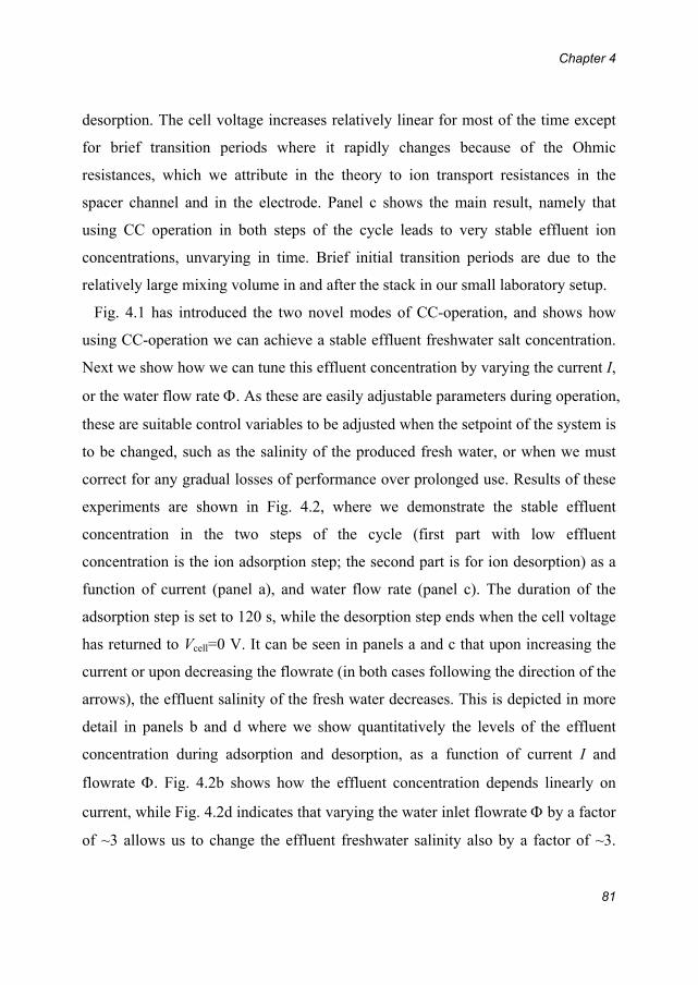
Chapter 4
81
desorption. The cell voltage increases relatively linear for most of the time except
for brief transition periods where it rapidly changes because of the Ohmic
resistances, which we attribute in the theory to ion transport resistances in the
spacer channel and in the electrode. Panel c shows the main result, namely that
using CC operation in both steps of the cycle leads to very stable effluent ion
concentrations, unvarying in time. Brief initial transition periods are due to the
relatively large mixing volume in and after the stack in our small laboratory setup.
Fig. 4.1 has introduced the two novel modes of CC-operation, and shows how
using CC-operation we can achieve a stable effluent freshwater salt concentration.
Next we show how we can tune this effluent concentration by varying the current I,
or the water flow rate . As these are easily adjustable parameters during operation,
these are suitable control variables to be adjusted when the setpoint of the system is
to be changed, such as the salinity of the produced fresh water, or when we must
correct for any gradual losses of performance over prolonged use. Results of these
experiments are shown in Fig. 4.2, where we demonstrate the stable effluent
concentration in the two steps of the cycle (first part with low effluent
concentration is the ion adsorption step; the second part is for ion desorption) as a
function of current (panel a), and water flow rate (panel c). The duration of the
adsorption step is set to 120 s, while the desorption step ends when the cell voltage
has returned to Vcell=0 V. It can be seen in panels a and c that upon increasing the
current or upon decreasing the flowrate (in both cases following the direction of the
arrows), the effluent salinity of the fresh water decreases. This is depicted in more
detail in panels b and d where we show quantitatively the levels of the effluent
concentration during adsorption and desorption, as a function of current I and
flowrate . Fig. 4.2b shows how the effluent concentration depends linearly on
current, while Fig. 4.2d indicates that varying the water inlet flowrate by a factor
of ~3 allows us to change the effluent freshwater salinity also by a factor of ~3.
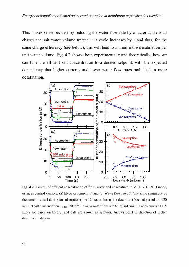
Energy consumption and constant current operation in membrane capacitive deionization
82
This makes sense because by reducing the water flow rate by a factor x, the total
charge per unit water volume treated in a cycle increases by x and thus, for the
same charge efficiency (see below), this will lead to x times more desalination per
unit water volume. Fig. 4.2 shows, both experimentally and theoretically, how we
can tune the effluent salt concentration to a desired setpoint, with the expected
dependency that higher currents and lower water flow rates both lead to more
desalination.
Fig. 4.2. Control of effluent concentration of fresh water and concentrate in MCDI-CC-RCD mode,
using as control variable: (a) Electrical current, I, and (c) Water flow rate, . The same magnitude of
the current is used during ion adsorption (first 120 s), as during ion desorption (second period of ~120
s). Inlet salt concentration csalt,in=20 mM. In (a,b) water flow rate =60 mL/min; in (c,d) current 1 A.
Lines are based on theory, and data are shown as symbols. Arrows point in direction of higher
desalination degree.
0
10
20
30
0 0.4 0.8 1.2 1.60
10
20
30
0
10
20
30
0 50 100 150 200
0
10
20
30
20 40 60 80 100Time (s)
Effl
uent
con
cent
ratio
n (m
M)
Adsorption
Adsorption
Desorption
Desorption
1.6 A
0.4 A
0.8
1.2
100 mL/min8060
40
Effl
uent
con
cent
ratio
n of
the
plat
eau
s (m
M)
current I:
flow rate :
Flow rate (mL/min)
Current I (A)
(a) (b)
(c) (d)
Desorption
Adsorption
Adsorption
Desorption
Concentrate
Freshwater
Concentrate
Freshwater

Chapter 4
83
Finally, we show in Fig. 4.3 a large data set for the energy consumption in CDI
and in MCDI, for the three operational modes discussed previously in Fig. 4.1, as a
function of operational mode, system layout (with/out membranes), and inflow salt
concentration, csalt,in. To be able to compare MCDI with CDI, we add here data for
CDI. Fig. 4.3 shows results both of experiments, and of the (M)CDI model. Note
that energy recovery during the ion desorption step, possible in the CC-RCD mode
of operation, is not included in this calculation, but it is discussed in section 6.3.
For the experiments reported in Fig. 4.3, operational conditions are the same as in
Fig. 4.1, except for the duration of each step in CV, which now is 500 s, and for the
fact that now we vary csalt,in. We observe that for MCDI a lower limit in energy
consumption is found of around 22 kT/ion removed. Beyond csalt,in=10 mM, this
value is quite independent of csalt,in for CC operation, while the energy consumption
increases moderately with csalt,in for CV-operation. For CDI, energy consumption is
higher than for MCDI, and more dependent on csalt,in, especially for CC-operation.
Fig. 4.3 shows in general somewhat lower energy consumption for CC-operation
than for CV-operation, but not as dramatic as a simple argument would suggest
based on the fact that in CC-operation the average cell voltage is lower; neither is
the energy-consumption in CC-operation higher than for CV-operation, which may
be inferred in first approximation when considering that with the voltage increasing
during the cycle, the energetic penalty for an extra ion to adsorb (for each electron
to be transferred against the growing cell voltage) will increase steadily. Instead we
find more subtle differences between the energy requirement in CC- and CV-
operation, differences which will depend on the durations of the adsorption- and
desorption steps, salt concentration, and chosen voltage and current levels.

Energy consumption and constant current operation in membrane capacitive deionization
84
Fig. 4.3. Energy consumption and dynamic charge efficiency in CDI and MCDI. Comparison of same
three operational modes as in Fig. 4.1, but now as a function of the inlet salt concentration, csalt,in. For
other parameter settings, see main text and Fig. 4.1. Panels a-c show the energy requirement per ion
removed, and panels d-f show the dynamic charge efficiency, dyn, being the ratio of the salt
adsorption vs charge. In all panels, lines are theory and points are data.
To explain, at least partly, the influence of the various variables on energy
consumption, we evaluate in the second row of Fig. 4.3 the dynamic charge
efficiency, dyn. This parameter denotes the ratio of two properties: the total
desalination during ion adsorption, divided by total charge transferred in that same
period. For technical details of this calculation, see the Experimental Section.
Making use of the data points in Fig. 4.3, we plot energy per ion removed vs.
dynamic charge efficiency for both CDI and MCDI in Fig. 4.4. MCDI data points
aggregate in the right bottom region of Fig. 4.4, corresponding to higher dynamic
charge efficiency dyn and lower energy per ion removed, while most CDI data are

Chapter 4
85
with lower dyn and higher energy per ion removed. Taking all data points into
consideration, it is observed that the energy per ion removed is strongly correlated
with dyn and that the energy decreases in a non-linear pattern as the dyn increases.
Fig. 4.4. Energy input per ion removed as a function of dynamic charge efficiency for CDI
and MCDI. Diamonds are CDI data; Circles are MCDI data. The dotted line is for guiding
the eyes.
Fig. 4.3, quite surprisingly, shows that the energy consumption does not decrease
steadily with increasing salt concentration, which in first approximation would be
expected because the ionic resistance in the spacer channel and macropores will
decrease with increasing salinity. Instead, we find that for MCDI the energy
consumption is fairly independent of salt concentration, while for CDI it even
increases with csalt. Though these experimental observations are well reproduced by
the theory, a simple argument to rationalize these counterintuitive results is not so
easily found.
0
20
40
60
80
0.2 0.4 0.6 0.8 1
Ene
rgy
inpu
t pe
r io
n re
mov
ed (
kT)
Dynamic charge efficiency (Λdyn)
CDI
MCDI

Energy consumption and constant current operation in membrane capacitive deionization
86
4.5 Conclusions
In conclusion, we have demonstrated that the use of constant electrical current
operation in membrane capacitive deionization (MCDI) results in a stable produced
freshwater concentration, not strongly varying in time. By tuning the level of the
electrical current, or the water flowrate, the freshwater salinity can be accurately
adjusted. We present an extensive data set for the energy requirements of water
desalination, both for CDI and for MCDI, and both for the constant current (CC)
and constant voltage (CV) mode of operation. According to both the data and the
theoretical model, in all situations considered, MCDI has lower energy
requirements than CDI, and this difference is larger for CC-operation than for CV-
operation. This difference correlates with higher dynamic charge efficiency (the
ratio of salt adsorption over charge) for MCDI relative to CDI. The theoretical
model reproduces most experimental data for MCDI well, though deviations
remain, especially for CDI at high ionic strength in CV-operational mode.
Nevertheless, the theoretical model is an essential tool to design and optimize the
MCDI system, and for the evaluation of the economic viability of this technology.
Chapter 5
87
Chapter5OptimizationofSaltAdsorptionRateinMembraneCapacitiveDeionization
embrane capacitive deionization (MCDI) is a water desalination technique
based on applying a cell voltage between two oppositely placed porous
electrodes sandwiching a spacer channel that transports the water to be desalinated.
In MCDI, ion-exchange membranes are positioned in front of each porous
electrode to prevent co-ions from leaving the electrode region during ion
adsorption, thereby enhancing the salt adsorption capacity. MCDI can be operated
at constant cell voltage (CV), or at a constant electrical current (CC). In this
chapter, we present both experimental and theoretical results for desalination
capacity and rate in MCDI (both in the CV- and the CC-mode) as a function of
adsorption/desorption time, salt feed concentration, electrical current, and cell
voltage. We demonstrate how by varying each parameter individually, it is possible
to systematically optimize the parameter settings of a given system to achieve the
highest average salt adsorption rate and water recovery.
This chapter has been published as:
Zhao, R., Satpradit, O., Rijnaarts, H. H. M., Biesheuvel, P. M. & Van der Wal, A. Optimization of salt
adsorption rate in membrane capacitive deionization. Water Research 47, 1941-1952 (2013)
M
Optimization of salt adsorption rate in membrane capacitive deionization
88
5.1 Introduction
Chapter 4 demonstrates operational modes of CDI and MCDI. The first
operational mode is also the most frequently used one in the literature, which is
applying a constant cell voltage (CV) between the electrodes during the adsorption
step, followed by short-circuiting of the electrodes, or reversing the voltage, during
the desorption step. Also it has been demonstrated that in MCDI charging and
discharging the electrodes at constant current (CC) can have several major
advantages in comparison with CV, such as a constant (i.e., not varying in time)
and adjustable effluent concentration (Chapter 4).
For all desalination technologies, it is essential to maximize the desalination
performance, i.e., the extent of desalination per unit time, besides optimizing the
water recovery (WR), which is the ratio of the flow of fresh water relative to the
flow of feed water. In the present manuscript, we focus exclusively on MCDI and
analyse the influence of several process parameters such as adsorption time, water
flowrate, and adsorption current on two key performance indicators in MCDI,
namely the average salt adsorption rate (ASAR) and water recovery, WR. We
discuss both the CC operational mode, as well as CV operation. The aim of this
chapter is to demonstrate how the average salt adsorption rate and the water
recovery can be systematically optimized for a given MCDI system.
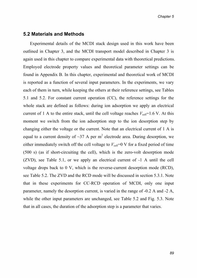
Chapter 5
89
5.2 Materials and Methods
Experimental details of the MCDI stack design used in this work have been
outlined in Chapter 3, and the MCDI transport model described in Chapter 3 is
again used in this chapter to compare experimental data with theoretical predictions.
Employed electrode property values and theoretical parameter settings can be
found in Appendix B. In this chapter, experimental and theoretical work of MCDI
is reported as a function of several input parameters. In the experiments, we vary
each of them in turn, while keeping the others at their reference settings, see Tables
5.1 and 5.2. For constant current operation (CC), the reference settings for the
whole stack are defined as follows: during ion adsorption we apply an electrical
current of 1 A to the entire stack, until the cell voltage reaches Vcell=1.6 V. At this
moment we switch from the ion adsorption step to the ion desorption step by
changing either the voltage or the current. Note that an electrical current of 1 A is
equal to a current density of ~37 A per m2 electrode area. During desorption, we
either immediately switch off the cell voltage to Vcell=0 V for a fixed period of time
(500 s) (as if short-circuiting the cell), which is the zero-volt desorption mode
(ZVD), see Table 5.1, or we apply an electrical current of -1 A until the cell
voltage drops back to 0 V, which is the reverse-current desorption mode (RCD),
see Table 5.2. The ZVD and the RCD mode will be discussed in section 5.3.1. Note
that in these experiments for CC-RCD operation of MCDI, only one input
parameter, namely the desorption current, is varied in the range of -0.2 A and -2 A,
while the other input parameters are unchanged, see Table 5.2 and Fig. 5.3. Note
that in all cases, the duration of the adsorption step is a parameter that varies.

Optimization of salt adsorption rate in membrane capacitive deionization
90
Table 5.1. Reference settings for MCDI-CC operation in ZVD mode.
Influent salt concentration (NaCl) 20 mM
Adsorption current (applied until the cell voltage reaches Vcell=1.6 V) 1 A (~37 A/m2)
Water flowrate (stack) 60 mL/min
Desorption time 500 s
Table 5.2. Reference settings for MCDI-CC operation in RCD mode. Except for desorption current,
all settings are fixed throughout section 5.3.1.2.
Influent salt concentration (NaCl) 20 mM
Adsorption current (applied until the cell voltage increases to Vcell=1.6 V) 1 A (~37 A/m2)
Water flowrate (stack) 60 mL/min
Desorption current (applied until the cell voltage decreases to 0 V) -0.2 to -2 A
For constant voltage operation (CV), we define the reference settings as follows:
A cell voltage of Vcell=1.2 V is applied during ion adsorption for 500 s, and during
ion desorption, we either immediately drop the cell voltage to Vcell=0 V for a fixed
duration of 500 s, which is the zero-volt desorption mode (ZVD), or we apply a
reversed voltage of -1.2 V, again for 500 s, which is the reverse-voltage desorption
mode (RVD). These two reference settings for CV were defined in Chapter 3 as
0-MCDI and r-MCDI. A full cycle consist of an ion adsorption step followed by an
ion desorption step. During both steps of the cycle, a 20 mM NaCl solution is
continuously pumped into the stack at a constant water flowrate of 60 mL/min for
the whole stack, which is equal to 7.5 mL/min per cell. The effluent is recycled
back to the reservoir (solution residence time in reservoir ~3 hour).
The salt adsorption and charge in an MCDI-cycle can be derived from the data of
the salt effluent (outflow) concentration versus time, and from the data for
electrical current versus time, respectively, following the procedures as explained
in previous Chapters. For salt adsorption, the difference in inflow salt
Chapter 5
91
concentration and outflow concentration is integrated with regard to time, and
multiplied with the water flowrate, while for charge, the current is integrated over
time. All data shown in this chapter are obtained under the DE condition.
5.3 Results and discussion
In this section, we first discuss desalination cycles for CC operation of MCDI
under the DE condition and show the influence on a series of performance
indicators, such as salt adsorption, charge transferred, and especially the average
salt adsorption rate (ASAR) and water recovery (WR), by varying the following
input parameters, namely: inflow salt concentration, adsorption current, water
flowrate, desorption time, and desorption current. We will show the results for each
parameter independently by varying each one in turn. In the second part of this
section we describe results of CV operation of an MCDI system, focusing on the
influence of cycle duration and desorption voltage. In all cases we compare
experimental results with theoretical model predictions. To describe the
desalination performance of MCDI theoretically, we use the process model for the
MCDI process as described in Chapter 3. Values of input parameters are
summarized in Appendix B.
5.3.1 Constant current (CC) operation of MCDI
5.3.1.1 Desorption in “Zero Volt Desorption”-Mode
In section 5.3.1 we present results of CC operation of MCDI in two operational
modes: zero-volt desorption (ZVD) and reverse-current desorption (RCD).
Fig. 5.1 presents results for MCDI-CC-operation in ZVD mode, where the
variation in effluent salt concentration during a single desalination cycle is shown.
Both experimental and theoretical results are presented, and as can be observed all
experiments can be well reproduced by the model. First of all, Fig. 5.1a shows that
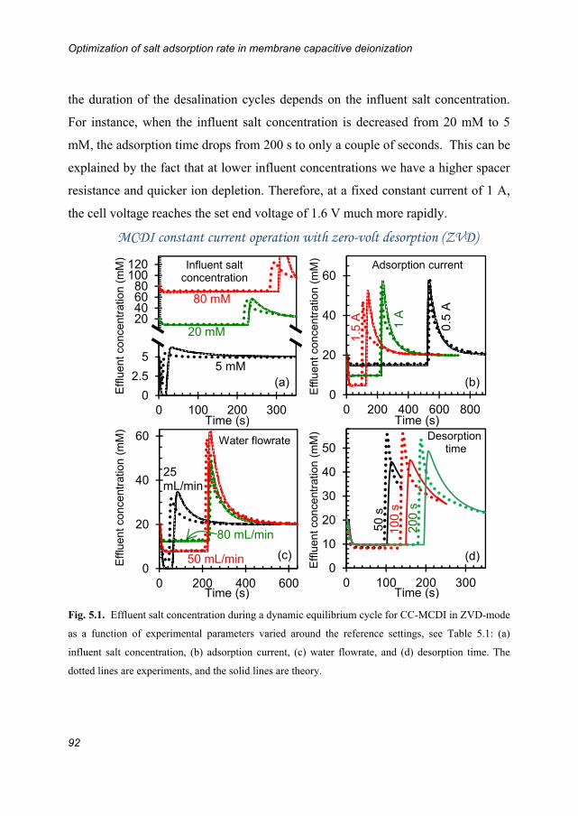
Optimization of salt adsorption rate in membrane capacitive deionization
92
the duration of the desalination cycles depends on the influent salt concentration.
For instance, when the influent salt concentration is decreased from 20 mM to 5
mM, the adsorption time drops from 200 s to only a couple of seconds. This can be
explained by the fact that at lower influent concentrations we have a higher spacer
resistance and quicker ion depletion. Therefore, at a fixed constant current of 1 A,
the cell voltage reaches the set end voltage of 1.6 V much more rapidly.
Fig. 5.1. Effluent salt concentration during a dynamic equilibrium cycle for CC-MCDI in ZVD-mode
as a function of experimental parameters varied around the reference settings, see Table 5.1: (a)
influent salt concentration, (b) adsorption current, (c) water flowrate, and (d) desorption time. The
dotted lines are experiments, and the solid lines are theory.
0
20
40
60
0 200 400 600 800
0
20
40
60
0 200 400 6000
10
20
30
40
50
0 100 200 300
020406080
100120
0
2.5
5
0 100 200 300
80 mM
20 mM
5 mM 5
0 s
1
00
s
20
0 s
1.5
A
1 A
0.5
A
80 mL/min
50 mL/min
25 mL/min
Time (s)Time (s)
Time (s)
MCDI constant current operation with zero-volt desorption (ZVD)
Eff
luen
t con
cent
ratio
n (m
M)
Adsorption current
Water flowrate Desorption time
Influent salt concentration
Time (s)
Eff
luen
t co
ncen
trat
ion
(mM
)
Eff
luen
t con
cent
ratio
n (m
M)
Eff
luen
t con
cent
ratio
n (m
M)
(a) (b)
(c) (d)
Chapter 5
93
In Fig. 5.1b and c it is shown that a lower effluent salt concentration can be
achieved by increasing the electrical current during the adsorption step, as well as
by decreasing the water flowrate. Fig. 5.1d shows that when we decrease the
desorption time, the adsorption capacity per cycle decreases and consequently the
adsorption time also becomes shorter. This is because a decrease in the desorption
time leads to incomplete release of counterions from the electrodes and
consequently leads to a lower ion removal in the next adsorption step.
It can be observed in Fig. 5.1b and c that by varying the current during ion
adsorption and/or by varying the water flowrate, the salt concentration in the
effluent can either be increased or decreased, and therefore in the CC mode it is
possible to fine-tune the salt concentration in the effluent water stream to a desired
level, see Chapter 4.
Data such as obtained for the experiments shown in Fig. 5.1 are presented in
aggregate form in Fig. 5.2 with each panel (a-d) in Fig. 5.1 corresponding to one
column (I-IV) in Fig. 5.2. In Fig. 5.2 row A we present the total cycle time (tcycle)
and the water recovery (WR) as a function of influent salt concentration (column I),
adsorption current (column II), water flowrate (column III), and desorption time
(IV). WR indicates the fraction of the salt stream which is reclaimed as fresh water.
WR can be calculated according to:
(5.1)
where is the water flowrate, tads the adsorption time, tdes the desorption time, and
tcycle is the sum of tads and tdes. As in our examples is always the same for the
adsorption and desorption step, we can use a simplified expression for WR
(=tads/tcycle).
ads ads
ads des cycle
t t
t t tWR

Optimization of salt adsorption rate in membrane capacitive deionization
94
Fig. 5.2. Experimental and theoretical results for operation of MCDI-CC in ZVD-mode. Water
recovery and total cycle time (tcycle) (row A), salt adsorption per cycle, per gram of total electrode
mass (row B), and average salt adsorption rate (ASAR) (row C). Each column describes the results
based on varying one input parameter at a time: column I influent salt concentration, column II
adsorption current, column III water flowrate, and column IV desorption time. Symbols are
experimental data, and lines are theory. Reference settings are given in Table 5.1.

Chapter 5
95
Results of salt adsorption are given in row B, both experimentally and
theoretically, as a function of the same four parameters (column I-IV). Fig. 5.2-B-I
shows that when the influent salt concentration is increased from close to zero to
around 20 mM, the salt adsorption rapidly increases, but after that the salt
adsorption again slightly decreases. Fig. 5.2-B-II shows that when the electrical
current during adsorption is increased, the salt adsorption decreases and when the
electrical current is above 1.5 A, the decrease is even faster. Fig. 5.2-B-III shows
the existence of two regions, one of low salt adsorption at a low flow rate <35
mL/min, and one of high salt adsorption for >35 mL/min. All the experimental
data can be reproduced very well with our theoretical model. However, some
phenomena, for instance the rapid increase of salt adsorption when the influent salt
concentration increases from zero to ~20 mM, or when the flowrate is increased
beyond ~35 mL/min, do not have a single and easy explanation and must be due to
the interplay of various process parameters.
For commercial use of an MCDI system it is important to have maximum salt
removal within a given period of time. Therefore, in order to evaluate how quickly
salt can be adsorbed, we introduce a new performance indicator, namely the
average salt adsorption rate (ASAR) (see Fig. 5.2 row C), which is the salt
adsorption per cycle, per gram of total electrode mass (Fig. 5.2-row B), divided by
the cycle time (Fig. 5.2-row A). Thus, ASAR is a measure of the average ‘speed’,
or rate, of salt adsorption. The data in Fig. 5.2-row C demonstrate that when we
vary each input parameter in turn, optimal values for ASAR are obtained in some
cases. Beyond 20 mM, ASAR is fairly independent of salinity (Fig. 5.2-C-I), and
independent of flowrate when flowrate is higher than 40 mL/min (Fig. 5.2-C-III).
However, a maximum ASAR is achieved at around ~1 A (Fig. 5.2-C-II), and at a
desorption time of 50 s (Fig. 5.2-C-IV). Note that these optimized input parameters
depend on the specific device, its operational mode, and values for other

Optimization of salt adsorption rate in membrane capacitive deionization
96
parameters. A general conclusion that can, however, be drawn is that the input
parameter settings that lead to the highest salt adsorption per cycle do not always
lead to the highest ASAR.
In addition, closer inspection of the results in Fig. 5.2 shows that for column III,
the trends in WR and ASAR are nearly the same. However, in column II when the
adsorption current is higher than 1 A, and in column IV when the desorption time
is higher than 50 s, the ASARs have the same declining trend as the water recovery.
Only in column I when the influent salt concentration is beyond 20 mM, the water
recovery increases slightly, while the ASAR levels off.
In brief, we have demonstrated that in the CC-ZVD mode, variation of input
parameters has a great impact on WR and on ASAR, which are the two most
important indicators to evaluate the performance of an MCDI system.
5.3.1.2 Desorption in “Reverse Current Desorption”-Mode
In a different operational mode, we apply a reversed current during desorption
until Vcell becomes zero again (RCD mode).
Fig. 5.3a shows that by applying a less negative current during the desorption
step, we extend the period of desorption and consequently also extend the duration
of the adsorption step. This leads to more salt removal per cycle, see Fig. 5.3c.
However, Fig. 5.3b shows that less negative desorption currents decrease the WR
and increase the total cycle time. Combination of these effects is shown in Fig.
5.3d, where we show that as the desorption current becomes more negative, ASAR
first increases and then decreases again. Thus, for this system, it is found that the
highest ASAR is at a desorption current between -0.8 and -1.8 A, while WR is
highest at a desorption current of -2 A.

Chapter 5
97
Fig. 5.3. Experimental and theoretical results for MCDI-CC operation in RCD mode. (a)
Effluent salt concentration as a function of time during one cycle. Dotted lines:
experiments, solid lines: theory. (b) Water recovery and total cycle time. (c) Salt adsorption
and charge per cycle per gram total electrode mass. (d) Average salt adsorption rate
(ASAR). For panels (b), (c) and (d) symbols are experimental data and lines are theory. See
Table 5.2 for reference settings.
0
0.1
0.2
0 0.5 1 1.5 2
0 0.5 1 1.5 20
10
20
30
40
0 100 200 300 400
-1.4 A
-0.8 A
-0.2 A
MCDI constant current operation with reverse-current desorption (RCD)
tcycle
Water recovery
Desorption current
Eff
luen
t co
nce
ntr
atio
n (m
M)
Wat
er
reco
very
Sa
lt a
dso
rptio
n (
mm
ol/g
)
AS
AR
(m
ol/g
/s)
Time (s) Desorption current (A)
Tim
e (
s)
Desorption current (A) Desorption current (A)
(a)
(b)
(c)
- -- -
Salt adsorption
----
0-- --0 0.5 1 1.5 2
0.6
0.4
0.2
0
200
400
600
800
0
0.2
0.4
0.6
0.8
1
ASAR
(d)
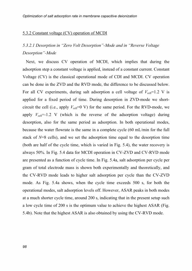
Optimization of salt adsorption rate in membrane capacitive deionization
98
5.3.2 Constant voltage (CV) operation of MCDI
5.3.2.1 Desorption in “Zero Volt Desorption”-Mode and in “Reverse Voltage
Desorption”-Mode
Next, we discuss CV operation of MCDI, which implies that during the
adsorption step a constant voltage is applied, instead of a constant current. Constant
Voltage (CV) is the classical operational mode of CDI and MCDI. CV operation
can be done in the ZVD and the RVD mode, the difference to be discussed below.
For all CV experiments, during salt adsorption a cell voltage of Vcell=1.2 V is
applied for a fixed period of time. During desorption in ZVD-mode we short-
circuit the cell (i.e., apply Vcell=0 V) for the same period. For the RVD-mode, we
apply Vcell=-1.2 V (which is the reverse of the adsorption voltage) during
desorption, also for the same period as adsorption. In both operational modes,
because the water flowrate is the same in a complete cycle (60 mL/min for the full
stack of N=8 cells), and we set the adsorption time equal to the desorption time
(both are half of the cycle time, which is varied in Fig. 5.4), the water recovery is
always 50%. In Fig. 5.4 data for MCDI operation in CV-ZVD and CV-RVD mode
are presented as a function of cycle time. In Fig. 5.4a, salt adsorption per cycle per
gram of total electrode mass is shown both experimentally and theoretically, and
the CV-RVD mode leads to higher salt adsorption per cycle than the CV-ZVD
mode. As Fig. 5.4a shows, when the cycle time exceeds 500 s, for both the
operational modes, salt adsorption levels off. However, ASAR peaks in both modes
at a much shorter cycle time, around 200 s, indicating that in the present setup such
a low cycle time of 200 s is the optimum value to achieve the highest ASAR (Fig.
5.4b). Note that the highest ASAR is also obtained by using the CV-RVD mode.
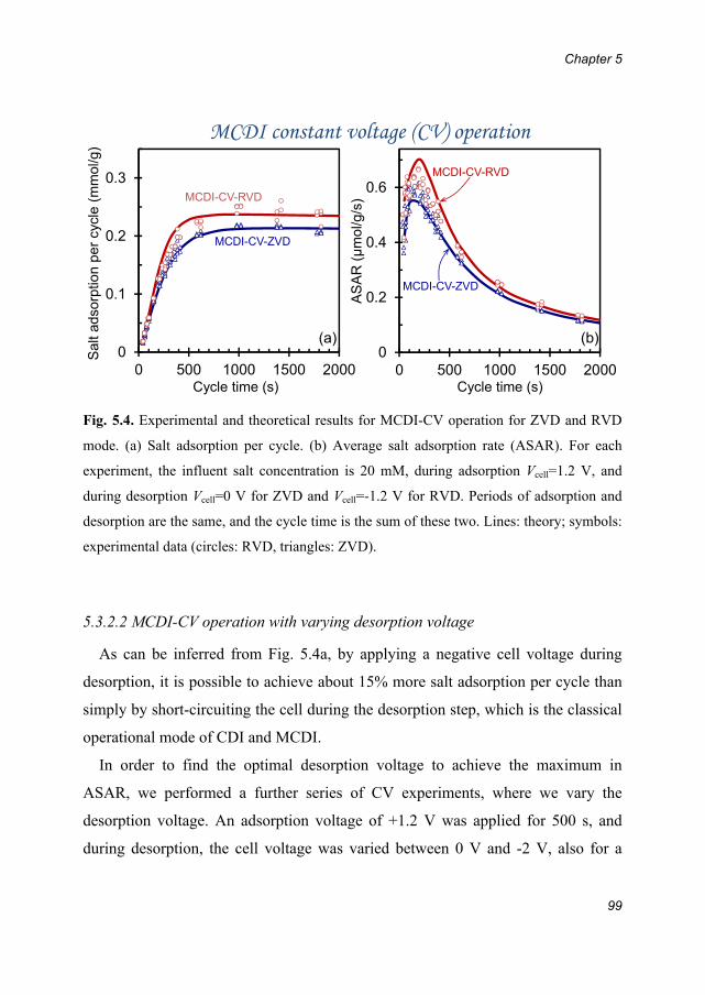
Chapter 5
99
Fig. 5.4. Experimental and theoretical results for MCDI-CV operation for ZVD and RVD
mode. (a) Salt adsorption per cycle. (b) Average salt adsorption rate (ASAR). For each
experiment, the influent salt concentration is 20 mM, during adsorption Vcell=1.2 V, and
during desorption Vcell=0 V for ZVD and Vcell=-1.2 V for RVD. Periods of adsorption and
desorption are the same, and the cycle time is the sum of these two. Lines: theory; symbols:
experimental data (circles: RVD, triangles: ZVD).
5.3.2.2 MCDI-CV operation with varying desorption voltage
As can be inferred from Fig. 5.4a, by applying a negative cell voltage during
desorption, it is possible to achieve about 15% more salt adsorption per cycle than
simply by short-circuiting the cell during the desorption step, which is the classical
operational mode of CDI and MCDI.
In order to find the optimal desorption voltage to achieve the maximum in
ASAR, we performed a further series of CV experiments, where we vary the
desorption voltage. An adsorption voltage of +1.2 V was applied for 500 s, and
during desorption, the cell voltage was varied between 0 V and -2 V, also for a
0
0.1
0.2
0.3
0 500 1000 1500 20000
0.2
0.4
0.6
0 500 1000 1500 2000
Sal
t ads
orpt
ion
per
cycl
e (m
mol
/g)
AS
AR
(μ
mol
/g/s
)
Cycle time (s) Cycle time (s)
(a) (b)
MCDI-CV-ZVD
MCDI-CV-RVD
MCDI-CV-RVD
MCDI-CV-ZVD
MCDI constant voltage (CV) operation

Optimization of salt adsorption rate in membrane capacitive deionization
100
duration of 500 s. As the total cycle time for each experiment is 1000 s, ASAR
follows the same trend as the salt adsorption per cycle shown in Fig. 5.5 and
consequently is not shown. Both experimental data and results of theoretical
calculations of salt adsorption and charge are presented in Fig. 5.5. It is observed
that salt adsorption and charge increase slightly with desorption voltage, with for
instance at a value of -1.4 V, approximately 15% more salt adsorption than for
desorption at 0 V. However, at voltages more negative than -1.0 V, the charge per
cycle increases strongly, which is not predicted by the model. For CDI, a similar
observation was made when increasing the cell voltage during adsorption [128].
We believe the effect is due to Faradaic reactions, e.g. water splitting, at high
desorption voltages. As a result, MCDI operated at very negative desorption cell
voltages utilizes more charge, resulting in a less energy-efficient salt adsorption
process, and is therefore not recommended.
Chapter 5
101
0
10
20
30
0
0.1
0.2
0.3
-0.5 0 0.5 1 1.5 2Desorption cell voltage (V)
-
Cha
rge
per
cycl
e (C
/g)
Sal
t ads
orpt
ion
per
cycl
e (m
mol
/g)
---
Salt adsorption
Charge
MCDI constant voltage (CV)
ZV
D
RV
D
0
Fig. 5.5. Salt adsorption and charge per gram of total electrode mass per cycle in MCDI-
CV as a function of negative desorption voltage (0 to -2 V). Influent salt concentration
csalt,in=20 mM, durations of the adsorption and desorption step each 500 s, and voltage
during adsorption Vcell=1.2 V. Symbols: data; lines: theory. Symbols intersected by the
dashed vertical lines correspond to the CV-ZVD and CV-RVD data at cycle time of 1000 s
in Fig.5.4.
5.3.3 Discussion
The interesting question is what can exactly be inferred from the data. Starting at
Fig. 5.2, a comprehensive data set for MCDI-CC operation in the ZVD-mode is
presented, focusing on the two key performance indicators for MCDI, namely
water recovery (WR) and average salt adsorption rate (ASAR). As can be observed,
varying influent salt concentration (column I), water flowrate (III), or desorption
time (IV), in all cases leads to a similar trend in WR and in ASAR, both either
going up or down with a change in one of the parameter settings. A deviation is
found in the dependence of ASAR and WR on the adsorption current (II), where

Optimization of salt adsorption rate in membrane capacitive deionization
102
the former has a maximum at an adsorption current around 1 A, while to achieve
the highest WR, the adsorption current must be minimized.
Next, Fig. 5.3 summarizes data for MCDI-CC in the RCD-mode of operation. In
this case we also find that ASAR and WR have a different dependency on the input
parameter that is varied, being in this case the adsorption current, with ASAR
being at a maximum for a fairly large range of values for the desorption currents
(between -0.8 and -1.8 A), while WR steadily increases with less negative
desorption currents. The results for MCDI-CV (Figs. 5.4 and 5.5) demonstrate that
optimum cycle times (to have the highest ASAR) are much shorter than typically
required for the carbon electrodes to get saturated in this thesis (often beyond 10
min, approaching one hour); here we find a maximum ASAR at a cycle time of
only 200 s, much shorter than previously used values. All of these results show that
the complete optimization of an MCDI system, considering also energy costs and
material properties, is a complicated task requiring multidimensional optimization.
In general, Figs. 5.1-5.5 show that our two-porosity modified-Donnan model
well describes the data when we fit the CV-data and CC-data separately, using as
freely adjustable parameters the membrane charge density X, the ion diffusion
coefficient in the membrane Dmem, the fraction of the total water flow going
through one electrode, , as well as the specific electrode resistance, Relec. However,
as may be observed from Appendix B, to fit these two large data sets (one for CV-
and the other for CC-operation), we need to use different numbers for X, Dmem and
. This is not an optimal situation and indicates that our model is not yet
fundamentally rigorous, because ideally one set of model parameters describes data
both for CC and CV operation at the same time. Several model improvements can
be made to help us achieve this aim, as summarized next: first of all, full porous
electrode theory has not yet been implemented, but instead we have assumed that
in each sub-cell we have equalized properties across the electrode, with the ionic

Chapter 5
103
resistance empirically described by a single parameter Relec. An improved model
makes use of porous electrode theory and does not need this parameter Relec.
Secondly, for the membrane we have assumed equal ion diffusion coefficients for
the counterion and the co-ion. However, as known from membrane open-circuit
voltage diffusion potential measurement [129], the co-ion can have a different
mobility (diffusion coefficient) from the counterion in the membrane. This effect
can be included in an improved model. Furthermore, the spacer channel is
modelled as a series of stirred tanks, and the exact concentration profile of ions
across the channel (in the direction from membrane to membrane) is not yet
considered. Finally, our model assumes perfect symmetry of anode and cathode,
which is not true in reality because the cation and anion have different diffusion
coefficients (both in the open space, and in the membranes), and because the anion-
exchange membrane and the cation-exchange membrane have a different charge
density. When all of these effects are included in a full-scale model, it is hopefully
possible to fit all presented data sets in Chapters 3-5 by one and the same model,
with one set of input parameters. Such a model can be confidently used for process
optimization studies.
Optimization of salt adsorption rate in membrane capacitive deionization
104
5.4 Conclusions
In Chapter 5 we have presented experimental and theoretical results for CC and
CV operation in the membrane capacitive deionization (MCDI) process. We have
systematically varied the following input parameters, namely influent salt
concentration, water flowrate, adsorption and desorption current, desorption
voltage, and adsorption and desorption times, and presented their effect on salt
adsorption per cycle, total charge, and water recovery (WR). We define the average
salt adsorption rate (ASAR) to evaluate the rate of desalination, and demonstrate a
systematic procedure to optimize the input parameters in order to reach the highest
ASAR. A theoretical MCDI process model is validated by comparison with
experimental data, with the outcome that in most cases the theory describes the
experimental results very well, though the need for parameter settings that differ
between CC and CV operation makes it clear that the model must be significantly
improved. In the future, an exact optimization of parameter settings can be realized
based on a validated MCDI process model, in order to obtain the highest ASAR
and WR for the operation of a particular MCDI system.
Chapter 6
105
Chapter6DiscussionsandConclusions
6.1 Introduction
This thesis deals with capacitive deionization and membrane capacitive
deionization from various perspectives. In Chapter 2, we illustrate the electrical
double layer structure inside the micropores of carbon electrode based on the
modified Donnan model. Combining the equilibrium model with a transport model,
we have demonstrated the simulation of the (membrane) capacitive deionization
process (Chapter 3). Then we discussed an alternative operational mode for MCDI,
which is more advantageous than the classical constant voltage operational mode
(Chapter 4). Finally, we discussed how to optimize the salt adsorption for the
MCDI process with respect to the maximum salt adsorption rate (Chapter 5).
Generally speaking, we provided a way to understand the (M)CDI process from the
very fundamental side of ion adsorption and analysed the performance of (M)CDI
systematically, and our findings can be of contribution to design an (M)CDI system.
In this chapter we will discuss various issues with regard to what can be further
modified or improved in our future work, and I will provide the reader with a
comparison of energy consumption between MCDI and reverse osmosis, which can
be used as an indicator to reveal the market prospect of a MCDI, followed by a
general conclusion.

Discussions and conclusions
106
6.2 Measurable properties of porous carbon electrodes and ion-
exchange membranes
In the theoretical work of this thesis, values of some properties are determined by
fitting theory to data. However, those parameters can be measured independently
with carefully designed experiments, which in the future can lead to improvement
on the modelling part of work. In this section, we will discuss those measureable
properties and possible ways to measure them.
6.2.1 Two porosities of porous carbon electrode
In this thesis, a two-porosity assumption was made to distinguish the electrode
pores into two different categories: micropores (i.e., intraparticle porosity) and
macropores (i.e., interparticle porosity). The microporosity “pmi” is obtained by
fitting theory to data in the equilibrium model, and the macroporosity “pmA” is
estimated. However in reality, these two porosities can actually be measured, if the
content of carbon and polymer binder of the electrode is known. According to Ref.
[130], they can be calculated via the following equations,
(6.1)
(6.2)
where elec and A stand for the thickness and exchange area of the electrode, melec ,
wcarbon, and wpolymer are electrode mass, weight fractions of the carbons, and polymer
material (i.e., polymer binder added for mechanical stability). For the weight
fractions, together wcarbon+wpolymer=1, if no other additives, e.g., carbon black, are
present in the electrode. Next, ρcarbon is the solid density of the carbon, which most
of the time is assumed to be around 1.95 g/cm3 for all carbons investigated [130],
elec elec carbon carbon elec polymer polymer mi
mAelec
A m w m w Vp
A
elec elec carbon carbon elec polymer polymer mA
mielec
A m w m w Vp
A

Chapter 6
107
and ρpolymer is density of polymer. Finally Vmi is the volume of pores inside carbon
(in transport theory called micropores), which can be measured by the nitrogen gas
sorption at -196C using, for instance, an Autosorb iQ MP (Quantachrome
instruments, Germany), and VmA is the volume of transport pathways outside the
particles (called in transport theory macropores), which is equal to .
6.2.2 Membrane charge density
In the thesis, the employed anion- and cation-exchange membranes are AMX and
CMX (Neosepta, Tokuyama, Japan), respectively. Their membrane charge
densities or ion-exchange capacities are assumed to be the same, either 3000 or
8000 mM per volume of water in the membrane, see Appendix B. In this thesis,
those values are selected by fitting the MCDI transport model to the experimental
data. However, the ion-exchange capacity can be measured by ion sorption
experiments under equilibrium conditions [131], where for AMX it is about 4800
mM and for CMX 6000 mM, or by the existing titration method [132-134]. The
measured numbers for AMX and CMX are somewhat different from each other,
and are also different from our employed values. Currently in the MCDI transport
model, we only consider half of the MCDI cell, and later on, the model can be
extended for a full cell, which allows both membranes to be included
independently.
6.2.3 Chemical attraction term for neutral salt adsorption at zero cell voltage
During the modelling work of the salt adsorption in micropores at the
liquid/electrode interface we have used the modified Donnan model which
incorporates a chemical attraction term, μatt. However, the value of this term is not
measured, but instead we used an empirical number which is derived from the
mA elecp A

Discussions and conclusions
108
fitting procedure of experimental data, either µatt=1.4 kT or 2 kT for Na+ and Cl-,
and 2.5 for Ca2+. In practice, this term can also be measured. Herewith we give two
possible solutions. One method is to firstly immerse the carbon electrode into a
solution with prior knowledge of its ion concentration c0. After sufficient time,
remove the carbon electrode from the solution, measure the concentration of ions
in the solution cend again. The difference of the ion concentration between the two
steps c0-cend times the volume of the solution Vs gives the adsorbed amount of ions.
Another method is the ion exchange method, mostly used in determining the ion-
exchange capacity of the ion-exchange membranes. We can first immerse the
porous carbon electrodes into a solution which contains a given ion species (e.g.
Na+) for sufficient time to let the adsorption take place, and then exchange the
adsorbed ions with another species of ions (e.g. Mg2+) by placing the carbon
electrode in its highly concentrated solution. In the end, after the exchange, the
concentration of initially adsorbed ions now in the concentrated solution can be
measured analytically by either inductively coupled plasma optical emission
spectrometry (ICP-OES) (for cations) or ion chromatography (IC) (for anions). The
two methods can be repeated several times at different concentrations in order to
explicitly derive the exact concentration of the adsorbed ions in the micropores as a
function of the bulk concentration in the electro-neutral conditions. Afterwards,
with the concentration of the adsorbed ions in the micropores and the concentration
in the macropores, the attraction term can be derived according to a simplified
version of the Eq. 2.4 at electro-neutral conditions without considering the cell
voltage, . The procedure can be used for determining the chemical
attraction term for different ions and its dependence on all parameters.
In the future, based on accurate measurement of all the above mentioned
properties in section 6.2, the theoretical model can be further modified in such a
j,miatt
j,mA
ln c
c
Chapter 6
109
manner that embraces more physical evidence instead of using assumed values or
values obtained from theory/data fitting.
6.3 Optimal data processing for maximum salt adsorption and
energy consumption
The salt adsorption and charge in an (M)CDI-cycle can be derived from the data of
salt concentration and electrical current versus time, following the procedure as
explained in previous chapters. For salt adsorption, the concentration difference
between the inflow and the outflow is integrated over time from the moment when
charging starts till its end, and multiplied with the water flowrate. For charge, the
current is integrated over time. In addition, energy consumption is also calculated
based on integrating the power (product of cell voltage Vcell and applied current I)
over the adsorption-step, which is already explained in Chapter 4. In the procedure,
the beginning and the end of a cycle is the moment when a step change of current
or voltage occurs. If the desorption time is not enough for complete ion release
(less than ~500 s), after DE condition is reached, normally there will be a
systematic delay of the salt adsorption/desorption as a function of time compared to
the current/voltage change, to be discussed later. Because of the delay, the data
analysis procedure can be further modified in order to reflect the “real” salt
adsorption and energy consumption. To begin with, we will present the analysis of
data under the dynamic equilibrium (DE) condition in detail for salt adsorption and
energy consumption. Fig. 6.1 shows an example of cycles of (a) effluent salt
concentration, (b) current, and (c) cell voltage obtained during the experiment,
where the influent is 40 mM NaCl solution, and the total water flowrate is 30
mL/min for a stack consisting of 8 cells. During the adsorption-step, an electrical
current (1 A) is applied for 100 s, and during the desorption-step, -1 A is applied

Discussions and conclusions
110
until the cell voltage drops to Vcell=0 V. Note here 1 A can translate to the current
density of 37 A/m2.
Fig. 6.1. Experimental results of (a) effluent concentration, (b) current and (c) cell voltage as a
function of time for MCDI at constant current. Influent: 40 mM NaCl. During the adsorption-step an
electrical current of 1 A was applied for 100 seconds, after that the current during the ion-release step
was controlled at -1 A until the cell voltage dropped back to 0 V for each cycle. In total a number of
10 cycles is shown, and the DE was reached after the 3rd cycle. See Fig. 6.2 for detailed view.
Taking the 7th cycle that is under the DE condition in Fig. 6.1 as an example, see
Fig. 6.2, once the electrical current is applied, the cycle starts. This is also the
beginning of the salt adsorption with respect to the data analysis in previous
chapters. Yet at this moment the effluent concentration is still higher than the
influent concentration, in other words, the ions at this moment are still being
released. It takes a few seconds for the effluent concentration to become lower than
the influent concentration, only then the “real” adsorption-step starts. This “real”
beginning of the adsorption step has a short systematic delay in comparison to the
moment when the electrical current is applied, and this delay can be found in all
cycles under the DE condition. Similarly, for desorption, when the current is
Chapter 6
111
reversed from 1 to -1 A (adsorption ends, desorption starts), it takes the effluent
concentration again a few seconds to rise above the influent concentration, and also
when the discharging ends (current is reversed to 1 A again), the effluent
concentration does not drop below the influent concentration immediately, but after
several seconds. This systematic delay, as described above, is mainly caused by the
continuous mixing of just produced fresh water with untreated water in the spacer
channel and in the additional volume present in the stack (free space which is not
filled with the MCDI cells), which occurs every time when the electrical current is
changed. Hence to show the real salt adsorption, instead of integrating the
concentration difference between influent and effluent from the point where the
current is applied till the current is reversed, we integrate over the time period from
point A (Fig. 6.2a), where the effluent concentration intersects the influent
concentration, to the second intersection, point B (Fig. 6.2a). Similarly for the salt
desorption, we integrate from point B to C, which is the third intersection of the
influent concentration and the effluent concentration (Fig. 6.2a).
Fig. 6.2. Example data for MCDI operation at constant current (CC). (a) Influent/effluent
concentration (mM) as a function of time. Dashed line: influent concentration; solid line: effluent
concentration. (b) Cell voltage (V) and current density (A/m2) as a function of time. Dashed line:
current density; solid line: voltage. (c) Power density (W/m2) that is the product of current and
voltage as a function of time.
Discussions and conclusions
112
Fig. 6.2b shows the electrical current density and the cell voltage as a function
of time, for the 7th cycle in the series presented in Fig. 6.1. To display the power
(W) as a function of time as shown in Fig. 6.2c, the current (I) and the
corresponding cell voltage at every moment in time are multiplied. The energy
consumption can be computed via integrating the power over the time for the
whole cycle. During the adsorption-step, the current (I) and the voltage (V) have
the same sign (+), and thus the power (W) has always a positive value, implying
ion adsorption costs energy. In Chapter 4, we only took the adsorption-step into
account in the energy calculation. However, during the desorption-step, ions are
released spontaneously thereby creating a negative current, and simultaneously the
cell voltage is gradually declining to zero, which result in a negative power,
meaning the system recover energy during the ion release-step, for example, by
powering another (M)CDI system or a rechargeable battery. In the new approach,
assuming all the released energy during the desorption-step can be recovered, we
can integrate the power over the whole cycle, and thus the total energy
consumption will be lower.
Using the new approach as an example, we re-analysed the data point at 200
mM (MCDI-CC-RCD) in Fig. 4.3, Chapter 4. Table 6.1 shows that with the new
analysing method, we are able to “increase” the salt adsorption and the dynamic
charge efficiency slightly, and “decrease” the energy consumption per ion removed
significantly. Apparently, when presenting data of CDI performance, it is
imperative to define the method of analysis.
Table 6.1. Comparison of salt adsorption, dynamic charge efficiency, and energy consumption per ion removed for the MCDI-CC-RCD data point at 200 mM in Fig. 4.3, Chapter 4, by two methods of analysis.
Chapter 4 Chapter 6
salt adsorption (mmol/g) 0.108 0.112
dynamic charge efficiency 0.75 0.78
energy consumption per ion removed (kT) 33 24

Chapter 6
113
6.4 Energy consumption for producing fresh water and
comparison with reverse osmosis
It is indubitable that the thermodynamic minimal energy required for
desalination is independent of the type of separation process [63]. However,
because of fundamental differences between desalination technologies, the energy
required to remove a given amount of salt can vary significantly. To testify if
MCDI can be competitive in the desalination world, here, we compare its energy
consumption per volume fresh water produced with the most prevalent technique,
reverse osmosis (RO). For the energy consumption of RO, data are obtained from
literature, see Appendix D; and for the comparison, a 13-cell MCDI unit is
constructed consisting 26 electrodes (e=383 m, and mtot=19.0 g). Apart from the
electrode weight and thickness, for the other experimental settings, see Chapter 3.
A series of experiments are performed on the 13-cell MCDI stack, and in all
cases we use NaCl as the influent salt solution. We flow solutions with the
concentration ranging from 0.4 to 5.2 g/L TDS (20 to 90 mM NaCl, 1 g/L
TDS=17.1 mM) into the stack, and desalinate them either to 0.5 g/L TDS (8.6 mM
NaCl) or to 1 g/L TDS (17.2 mM NaCl), in both cases using the CC-RCD mode
(Iads=-Ides, desorption until Vcell back to zero), where the duration of both the
adsorption and the desorption step is 120 s (water recovery WR=50%, the water
flow rate is 30 mL/min per stack, and the required electrical adsorption current Iads
to achieve this aim is given in the Fig. 6.3b). The two freshwater concentration
levels defined above represent palatable drinking water (with good taste), and the
limit of drinking water, respectively [135]. As presented in Fig. 6.3a, the majority
of energy consumption data for large scale RO system is below 2 kWh/m3 within
the whole concentration range. In the case of MCDI, if the product salinity is below
1 g/L TDS, (diamonds in Fig. 6.3a), when the influent salt content is below ~3 g/L,
MCDI can be advantageous over RO. However if even purer water (~0.5 g/L TDS)

Discussions and conclusions
114
has to be produced, the energy consumption for each influent salt concentration is
nearly doubled. As a result, MCDI becomes competitive only if the influent salt
concentration is below 2 g/L TDS. Note that in this study the pumping energy of
MCDI is not included. Unlike RO, MCDI does not need a high pressure to press
water through the membrane, but instead, water is transported only in between the
two ion-exchange membranes, which does not require a substantial pressure drop
between the influent and the effluent of the stack. Since our system is not
optimized for industrial objectives, the energy consumption can be further reduced
by e.g. optimizing the system or reducing the electronic resistances. To conclude,
MCDI has the potential to compete with RO to desalinate brackish water, and the
future research on MCDI could focus on reducing the energy consumption, which
is the most relevant issue to the application.
Fig. 6.3. (a) Comparison of energy consumption between MCDI and Reverse Osmosis. Triangles:
energy consumption of MCDI to treat influent salt concentration to < 0.5 g/L TDS (palatable drinking
water). Diamonds: energy consumption of MCDI to treat influent salt concentration to < 1 g/L TDS
(limit drinking water). Circles: RO data. The data sources for RO are listed in Appendix D. Dashed
lines are for guiding the eyes. (b) Electrical adsorption current (Iads) applied to the MCDI stack in
order to achieve the effluent salt concentration levels for the two different effluent salt concentrations.
0
1
2
3
4
5
Influent salt concentration (g/L TDS)
MCDI0.5 g/L TDS
MCDI1g/L TDS
RO
012345
0 2 4 6
Cur
rent
(A
)
(a)
(b)0.5 g/L TDS
1g/L TDS
MCDI

Chapter 6
115
6.5 General conclusions and perspectives
In this thesis, we have investigated many aspects of the capacitive deionization
technologies, such as the fundamental electrical double layer properties of carbon
electrodes under equilibrium conditions, advantages of the use of ion-exchange
membranes, and operational modes for (M)CDI. We used the modified Donnan
model combined with the transport model to further understand the adsorption and
transport process of (M)CDI. Future research should focus on further optimization
of the (M)CDI system in the following respects:
Investigate the most suitable porous carbon electrodes, which have the optimal
pmA/pmi ratio, and highest porosity.
Improve the design of the system to reduce the ionic transport resistance
thereby decreasing the energy consumption by e.g. adding carbon black to the
carbon electrodes, coating membranes on the surface of the porous carbon
electrodes, etc.
Investigate the durability of the (M)CDI system, discover its resistance to
scaling and biofouling, design proper pre- and post-treatment measures to
meet requirements from different applications.
Besides desalination, discover other possible applications by using the
(M)CDI technology, e.g., recover valuable metals from waste streams with or
without ion selective membranes.
To conclude, this thesis links the theory to the experimental results of (M)CDI. By
fitting the modified Donnan model to the experimental equilibrium data, a series of
theoretical properties has been discovered, thereby leading to better understanding
of the CDI salt adsorption mechanism. By embedding the validated modified
Donnan model into a transport model based on a few reasonable assumptions of
electrode and ion-exchange membranes, we are able to reproduce changes of many

Discussions and conclusions
116
variables as a function of time, e.g. salt effluent concentration, electrical current,
ion concentration in the macropores, for both CDI and MCDI processes. The
constant current operational mode of MCDI was also proposed, in order to advance
the feasibility of this technology. Moreover, MCDI was proved to be more energy-
efficient than CDI, and in the end, we optimized the operational mode of MCDI by
varying the experimental settings so as to reach a maximum salt adsorption rate.

Appendix A
117
AppendixASummaryofCDIsaltadsorptionbyusingdifferentelectrodematerials
In this appendix, we summarize reported data from the literature for the important
CDI property of salt adsorption per gram of electrode material. Here, data are given
as a function of salinity and cell voltage, per gram of both electrodes combined.
The experiment in all cases is done in a symmetric cell with the two electrodes of
the same mass and material. As can be read off from Table A, reported numbers
vary in a large range between ~0.7 and ~15 mg adsorbed salt /g electrode mass.
In Table A, we distinguish the operational mode of CDI into two methods. One is
called single-pass (SP)-method, where water is fed from a storage vessel and the
salinity (conductivity) of the water leaving the cell is measured directly at the exit
of the cell or stack, like what we used in the thesis, see Fig. Aa. In this case the
measured effluent salinity will start to drop soon after applying the cell voltage.
Later on, however, the effluent (measured) salinity rises again to the inlet value,
because the electrodes have reached their adsorption capacity. The effluent water is
either discarded or can be recycled to a reservoir container. This reservoir needs to
be large to ensure that concentrations here only change very slightly within the
adsorption half of the cycle, say less than 1%, to make sure that the influent
concentration remains virtually constant during the cycle. In another common
approach, called the batch-mode (BM) method, the recycling reservoir is much
smaller, and it is in this container where the water conductivity is measured, which
steadily drops during the ion adsorption step to reach a constant final value, see Fig.
Ab.

Summary of CDI salt adsorption by using different electrode materials
118
Fig. A. Schematic of two designs for CDI experiments. (a) Single-pass experiment (SP-method): The
water conductivity is measured at the exit of the stack, or cell, and the outflow is discarded afterwards
or recycled to a large container. (b) Batch-mode experiment (BM-method): The conductivity is
measured in a (small) recycle beaker.

Appendix A
119
Table A. Overview of NaCl salt adsorption performance reported for different electrode materials
applied for CDI.
Ref. Carbon material
Experimental conditions NaCl salt adsorption
(mg/g) Initial salt
concentration (mg/L)
Cell voltage
(V)
Carbon content
(%)
Operational mode
[136] ordered mesoporous
carbon-carbon nanotube ~46 1.2 80 BM 0.63
[37] ordered mesoporous
carbon ~25 1.2 78 BM 0.68
[36] ordered mesoporous
carbon ~50 0.8 78 BM 0.93
[137] MnO2 activated carbon ~25 1.2 n/a BM 1
[47] graphene-like nanoflakes ~25 2 80 BM 1.3
[138] graphene-carbon nanotube ~29 2 90 BM 1.4
[66] carbon aerogel ~50 1.2 n/a BM 1.4 ~500 1.2 n/a BM 2.9
[139] multi-walled carbon
nanotubes ~3000 1.2 n/a BM 1.7
[51] graphene ~25 2 100 BM 1.8
[140] reduced graphene oxide-activated carbon
~50 1.2 n/a BM 2.9
[141] reduced graphite oxidate-
resol ~65 2 80 BM 3.2
[46] carbon nanotubes-
nanofibers ~110 1.2 100 BM 3.3
[123] activated carbon ~200 1.5 n/a SP 3.7
[33] Ti-O activated carbon
cloth ~5844 1 n/a BM 4.3
[142] carbon nanofiber webs ~95 1.6 100 BM 4.6
[143] sulphonated graphite
nanosheet ~250 2 72 BM 8.6
[55] carbon aerogel monoliths ~2922 1.5 100 BM 9.6
[144] single-walled carbon
nanotubes ~23 2 70 BM 0.75 ~292 1.2 n/a SP 10.5
This thesis
commercial activated carbon electrode
~292 1.2 n/a SP 10.9 ~1170 1.4 n/a SP 13
[39]
activated carbon (Norit DLC Super 50)
~292 1.2 85 SP 6.9 ~292 1.4 85 SP 8.4 ~292 1.2 85 SP 12.4
carbide-derived carbon ~292 1.4 85 SP 14.9

Summary of CDI salt adsorption by using different electrode materials
120
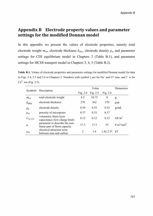
Appendix B
121
AppendixBElectrodepropertyvaluesandparametersettingsforthemodifiedDonnanmodel In this appendix we present the values of electrode properties, namely total
electrode weight mtot, electrode thickness δelec, electrode density ρe, and parameter
settings for CDI equilibrium model in Chapters 2 (Table B.1), and parameter
settings for MCDI transport model in Chapters 3, 4, 5 (Table B.2).
Table B.1. Values of electrode properties and parameter settings for modified Donnan model for data
in Figs. 2.4, 2.5 and 2.6 in Chapters 2. Numbers with symbol ‡ are for Na+ and Cl- ions, and † is for
Ca2+ ion (Fig. 2.5).
Symbols Description Value Dimension
Fig. 2.4 Fig. 2.5 Fig. 2.6
mtot total electrode weight 8.5 10.75 8 g
δelec electrode thickness 270 362 270 m
ρe electrode density 0.58 0.55 0.55 g/mL
pmi porosity of micropores 0.37 0.33 0.37
CSt,vol,0 volumetric Stern layer capacitance (low charge limit)
0.12 0.12 0.12 GF/m3
parameter to describe the non-linear part of Stern capacity
17.3 17.3 35 F•m3/mol2
μatt chemical attraction term between ions and carbon
2 1.4 1.4‡ 2.5† kT

Electrode property values and parameter settings for the modified Donnan model
122
Table B.2. Parameter settings for theoretical (M)CDI transport process model for Chapters 3, 4 and 5.
Numbers with symbol † are for section 3.5.1 (Fig. 3.4), and ‡ for section 3.5.2 (Figs. 3.5-3.7) in
Chapter 3. In Chapter 4, numbers with subscripts cc are for constant current operation (Figs. 5.1-5.3)
and subscripts cv denote constant voltage operation (Figs. 5.4-5.5). ‘n/a’ denotes the parameters
which are not applicable at certain cases. S
ymbols
Description
Value
Dim
ension C
hapter 3 C
hapter 4 C
hapter 5
mtot
total electrode weight
8.5†
10.75‡ 10.75
10.75 g
δelec electrode thickness
270† 362‡
362 362
um
ρe
electrode density 0.58†
0.55‡ 0.55
0.55 g/m
L
pm
i porosity of m
icropores 0.37†
0.30‡ 0.3
0.3
pm
A porosity of m
acropores 0.3
0.3 0.3
CSt,vol,0
volumetric S
tern layer capacitance (low charge lim
it) 0.12
0.12 0.12
GF
/m3
parameter to describe
non-linear part of Stern capacity
17.3 17.3
17.3 F•m
3/mol 2
Relec
specific electrode resistance 0.108
0.108 0.12
cc 0.108
cv W
•mol/m
X
fixed mem
brane charge density n/a†
8000‡ 3000
3000cc
8000cv
mol/m
3
D
ion diffusion coefficient in the spacer channel 1.68
1.68 1.68
10-9 m
2/s
Dm
em ion diffusion coefficient in the m
embrane
n/a† 0.168‡
1.12 1.12
cc 0.168
cv 10
-9 m2/s
Vsp
total volume of one spacer channel
0.147
0.147 0.147
mL
Velec
total volume of one electrode
0.114† 0.153‡
0.153 0.153
mL
Vdead
dead volume in the stack
50† n/a‡
n/a n/a
mL
fraction of total flow
going through one electrode 0%
† 0.25 %
‡ 1%
1%
cc 0.25%
cv
μatt
chemical attraction term
between ions and carbon
2† 1.4‡
1.4 1.4
kT
M
number of sub-cells in the m
odel 6
6 6
Ccap
capacitance in the external circuit n/a
n/a 2cc
n/acv m
F/m
2

Appendix C
123
AppendixCModificationontheMCDIelectriccircuitmodelbyplacingasmallcapacitanceinParallel
In this appendix we present a schematic diagram of the electric circuit analogue of
the MCDI system, see Fig. D. In our numerical code, to avoid problems that occur
when we apply a step change in current to the MCDI cell, we have placed a very
small capacitance in the external circuit, Ccap=2 mF/m2, parallel to the MCDI cell,
so the applied electrical current, Imax, will first saturate the small capacitor and then
charge the system with current Itot, according to .
Initially, because of the spacer channel resistance, all the applied current, Imax,
goes to the external capacitor, thus initially the current to the MCDI cell will be
zero, Itot=0. However, in time, when the external capacity saturates, Icap becomes
zero, and the average current into the MCDI cell, Itot, will approach the value of
Imax. Note that in the model Itot distributes self-consistently over the M numerical
sub-cells in one actual cell, see Fig. 3.2 in Chapter 3.
cell max tot
cap
d
d
V I I
t C
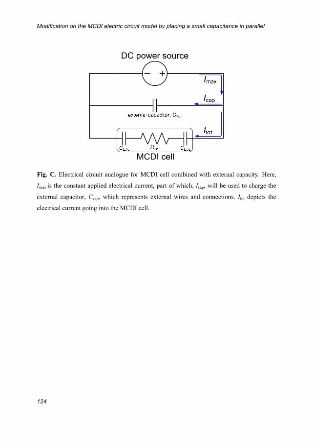
Modification on the MCDI electric circuit model by placing a small capacitance in parallel
124
Fig. C. Electrical circuit analogue for MCDI cell combined with external capacity. Here,
Imax is the constant applied electrical current, part of which, Icap, will be used to charge the
external capacitor, Ccap, which represents external wires and connections. Itot depicts the
electrical current going into the MCDI cell.

Appendix D
125
AppendixDSummaryofenergyconsumptionofreverseosmosisplants
In this appendix, we present various data of Reverse Osmosis plants found in the
literature [145-154] used for the comparison of energy consumption between
MCDI and RO in Chapter 6.
Table D. Examples of configurations of reverse osmosis plants.
Location
Feed water
concentration
(g/L)
Capacity
(m3/d)
Energy
Consumption
(kWh/m3)
Water
cost
(US$/m3)
Year of
data
access
Water
Recovery Reference
Elhamarawien, EG 3.5‡ 53 0.89 11.6 1986 n/a [145]
White Cliffs, AU 3.5‡ 0.5 2 9 2003 n/a [145]
Solar flow, AU 5‡ 0.4 1.86 10~12 1982 n/a [145]
Conception del Oro, MX 3‡ 0.71 6.9 n/a 1982 n/a [145]
Mesquite, US 3.5‡ 1.5 1.38 3.6 2003 n/a [145]
Denver, US 1.6‡ 1.5 1.4 6.5 2003 n/a [146]
Hassi-Khebi, DZ 3.5‡ 0.85 2.1 10 1987 n/a [146]
Pine Hill, AU 5.3‡ 1.1 1.5 3.7 2008 n/a [146]
Ksar Ghilene, TN 3.5‡ 7 2.1 6.5 2005 n/a [146]
Heelat Ar Rakah, OM 1.01‡ 5 2.3 6.5 1999 n/a [146]
Univ. of Almeria, ES 3.36‡ 8.09 2.5 2.5 1988 n/a [146]
Coite-Pedreiras, BR 1.2‡ 6 3 12.8 2000 n/a [146]
Seriwa, Perth, AU 5.7‡ 0.55 4.9 9.6 1982 n/a [146]
Lampedusa, IT 8‡ 40 5.5 10.6 1990 n/a [146]
VARI-RO, US 7‡ 3.6 2.4 9 1999 n/a [146]
Baja California Sur, MX 4‡ 11.5 2.6 9.8 2005 n/a [146]
Lipari, IT 8‡ 13.7 6.5 10.6 1991 n/a [146]
Univ. of Athens, GR 0.4‡ 1000 7.7 2.8 2000 n/a [146]
Cadarache, FR 2† 15 0.7 n/a 1978 n/a [147]
El Hamrawein, EG 3† 216 1 n/a 1981 n/a [148]
Maagan Michael, ES 4‡ 6.8 5 3 1997 n/a [149]
Caple, ES 6† 4000 1.72 0.29 2002 n/a [150]
Vall D'Uixo, ES 1.125† 7500 0.6 0.14 1997 n/a [150]
Nules, ES 1.529† 6000 0.83 0.17 2002 n/a [150]
Cuevas de Almanzora,
ES 6.75† 25000 1.2 0.246 2003 n/a [150]
Drenajes, ES 6.25† 6000 1.2 0.3 1997 n/a [150]
Terciario Alacanti Norte,
ES 1.75† 5000 1.55 0.36 2010 n/a [150]

Summary of energy consumption of reverse osmosis plants
126
In Table D, feed water concentrations presented with ‡ are converted from ppm,
and with † are converted from conductivity measurement (μS/cm). During
conversion 1 ppm is assumed to be equal to 1 mg/L, and 1μS/cm is assumed to be
equal to 0.5 mg/L, according to Refs. [155, 156]. “n/a” denotes “not available”.
Citrico del Andevalo, ES 0.6† 1200 0.86 0.14 2007 90% [150]
Sidmed, ES 0.4† 750 1.2 0.22 1995 n/a [150]
Xeresa Golf, ES 1.7† 5000 0.85 0.29 2003 n/a [150]
Alicante University, ES 3.2† 450 1.1 0.22 1996 n/a [150]
AENA, ES 0.9† 200 1 0.18 1999 n/a [150]
San Vicente del Raspeig,
ES 4.25† 100 1 0.25 1998 n/a [150]
Gaza Strip area 1.625 60 1.35 n/a 1993 75% [151]
Ceara, BR 1.2‡ 6 3.03 n/a 2000 27% [152]
Gran Canaria, ES 3.36‡ 0.8 2.48 n/a 1988 26-64% [152]
Algeria 3‡ 22.4-26.4 2.075 n/a 1988 24-
40.7% [152]
Egypt 4.4‡ 0.24 0.89 n/a 1986 51% [152]
Jordan 1.7‡ 0.22-1.27 1.9 n/a 2011 22% [153]
Kerkennah Islands, TN 3.7 3300 1.1 n/a 2003 75% [154]

Appendix E
127
AppendixEOutlineofGouy‐Chapman‐Sternmodel
In this appendix, we will generally outline the Gouy-Chapman-Stern (GCS) model,
which is the classical electrical double layer (EDL) theory, used for salt adsorption
and charge transferred at equilibrium in Capacitive Deionization. The GCS model
considers two layers at the surface of a plane electrode in the aqueous phase. The
two layers are the Stern layer and the diffuse layer. The Stern layer is assumed to
be the inner layer attaching the electrode surface, where ions are absent, and only
solvent molecules (H2O in our case) exist. The outside boundary of the Stern layer
is also called Outer Helmholtz Plane (OHP), from which the diffuse layer extends
outwards to the bulk solution. It is assumed that in the diffuse layer the ions obey a
Boltzmann distribution law. Fig. E illustrates an analogy to the EDL disregarding
any specific adsorption that we also ignore in our work. Normally the length of the
diffuse layer is defined by the Debye length λD, for a 1:1 salt ,
where c is the salt concentration of the electrolyte, Nav is the Avogadro number,
and λB is the Bjerrum length (=0.72 nm in water at room temperature). In a dilute
electrolyte, e.g. 5~20 mM NaCl, λD is usually several nm, which is larger than the
micropore diameter (~2 nm) of the porous carbon electrode. As a result, strong
double layer overlap will occur, which is also the reason why we use the modified
Donnan model to describe the EDL in the carbon micropores.
1
2D av B8
c N
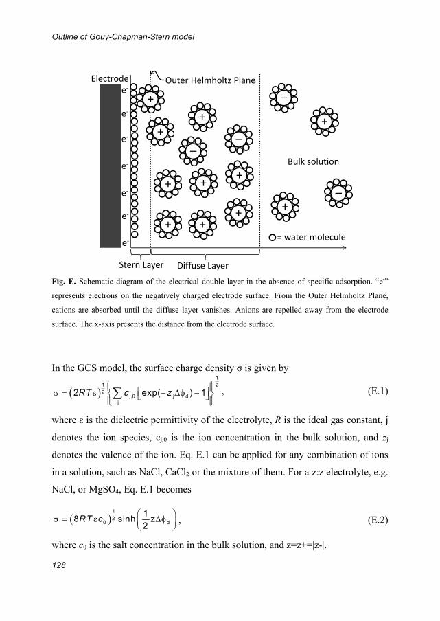
Outline of Gouy-Chapman-Stern model
128
Fig. E. Schematic diagram of the electrical double layer in the absence of specific adsorption. “e-”
represents electrons on the negatively charged electrode surface. From the Outer Helmholtz Plane,
cations are absorbed until the diffuse layer vanishes. Anions are repelled away from the electrode
surface. The x-axis presents the distance from the electrode surface.
In the GCS model, the surface charge density σ is given by
, (E.1)
where ε is the dielectric permittivity of the electrolyte, R is the ideal gas constant, j
denotes the ion species, cj,0 is the ion concentration in the bulk solution, and zj
denotes the valence of the ion. Eq. E.1 can be applied for any combination of ions
in a solution, such as NaCl, CaCl2 or the mixture of them. For a z:z electrolyte, e.g.
NaCl, or MgSO4, Eq. E.1 becomes
, (E.2)
where c0 is the salt concentration in the bulk solution, and z=z+=|z-|.
Electrodee‐
e‐
e‐
e‐
e‐
e‐
e‐
+
+
+
+
__
+
+ +
_
Diffuse Layer
Bulk solution
Stern Layer
+
+
+
+
_
= water molecule
Outer Helmholtz Plane
1
1 22
d2 exp( ) 1 RT j,0 jjc z
1
20 d8 sinh
RT c1 z2

Appendix E
129
On the electrode surface the ion distribution obeys the Boltzmann distribution law,
and thus the ion concentration at distance x from the OHP cj(x) can be related to
the ion concentration in the bulk solution, cj,0, given by
, (E.3)
where (x) denotes the potential at distance x in the diffuse layer. Therefore, the
excess number of ion j at any distance from the OHP is
. (E.4)
By integrating Eq. E.4, the general equation for excess surface ion adsorption is
. (E.5)
For 1:1 salt, Eq. E.5 can be integrated for both cation (Eq. E.6) and anion (Eq. E.7),
, (E.6)
, (E.7)
where + is the excess surface cation adsorption, and - is the excess surface anion
adsorption. Thus the total salt adsorption per surface area salt is the sum of the two,
given by Eq. E.8:
, (E.8)
and the surface charge density is the difference of + and -, multiplied by the Faraday constant, according to
, (E.9)
By taking the ratio of surface salt adsorption to surface charge, the charge
efficiency of the 1:1 salt can be derived,
( ) exp( ( )) x xj j,0 j dzc c
( ) exp( ( )) 1 x xj j,0 j,0 j dzc c c
0
exp( ( )) 1
x xj j,0 j dz dc
12 exp 1
2
+ d 0 dc
12 exp 1
2
- d 0 dc
2 exp exp 2 4 cosh 12 2 2
d d dsalt + - d 0 d 0c c
( ) 2 exp exp 4 sinh
2 2 2
F F Fd d d+ - d 0 d 0c c

Outline of Gouy-Chapman-Stern model
130
. (E.10)
For 1:2 salt, and for mixed electrolyte solutions, a numerical solution for salt
adsorption is given in Ref. [157], however, it is also possible to derive the algebraic
equation for those more complex conditions. For instance, we derived the
equations for the mixture of NaCl and CaCl2,
, (E.11)
, (E.12)
where u=exp(-Δd), the ratio of ion concentrations outside the EDL is given by
1=cCa,0/cNa,0, and .
salt dcosh 1
2= tanh4sinh
2
F
1 1 12 1
1 1 1
1 2 ( 1) 2 ( 2) 1ln
1 4 2 (3 1)
u u uNa
2 1 1
1( ( 2) 1 3 1)
2 u uCa Na
T Na,0 /(2 ) V c F

References
131
References1. Cipollina, A., Seawater desalination : conventional and renewable energy
processes 2009, Berlin: Springer. 2. Shiklomanov, I.A. Appraisal and assessment of world water resources. Water Int.,
25, 11 (2000). 3. Buerkle, T. Making every drop count. 2007 [cited 2007 14 Feb.]; Available from:
http://www.fao.org/newsroom/en/news/2007/1000494/index.html. 4. Shannon, M.A., P.W. Bohn, M. Elimelech, J.G. Georgiadis, B.J. Marinas, and
A.M. Mayes. Science and technology for water purification in the coming decades. Nature, 452, 301 (2008).
5. Semiat, R. Energy Issues in Desalination Processes. Environmental Science & Technology, 42, 8193 (2008).
6. Schiermeier, Q. Purification with a pinch of salt. Nature, 452, 260 (2008). 7. Anderson, M.A., A.L. Cudero, and J. Palma. Capacitive deionization as an
electrochemical means of saving energy and delivering clean water. Comparison to present desalination practices: Will it compete? Electrochimica Acta, 55, 3845 (2010).
8. Fritzmann, C., J. Löwenberg, T. Wintgens, and T. Melin. State-of-the-art of reverse osmosis desalination. Desalination, 216, 1 (2007).
9. Avlonitis, S.A., K. Kouroumbas, and N. Vlachakis. Energy consumption and membrane replacement cost for seawater RO desalination plants. Desalination, 157, 151 (2003).
10. Arras, W., N. Ghaffour, and A. Hamou. Performance evaluation of BWRO desalination plant — A case study. Desalination, 235, 170 (2009).
11. Wilson, J.R., Demineralization by electrodialysis. 1960: Butterworths Scientific Publications.
12. Sonin, A.A. and R.F. Probstein. A hydrodynamic theory of desalination by electrodialysis. Desalination, 5, 293 (1968).
13. Ortiz, J.M., E. Expósito, F. Gallud, V. García-García, V. Montiel, and A. Aldaz. Desalination of underground brackish waters using an electrodialysis system powered directly by photovoltaic energy. Solar Energy Materials and Solar Cells, 92, 1677 (2008).
14. Strathmann, H., Electrodialysis in Membrane Separation System: Recent Developments and Future Directions, R.W. Baker, Editor. 1991, Noyes Data Corporation: Park Ridge, NJ. p. 396.
15. Cath, T.Y., A.E. Childress, and M. Elimelech. Forward osmosis: Principles, applications, and recent developments. Journal of Membrane Science, 281, 70 (2006).
16. Sharma, P. and T.S. Bhatti. A review on electrochemical double-layer capacitors. Energy Conversion and Management, 51, 2901 (2010).
17. Porada, S., R. Zhao, A. van der Wal, V. Presser, and P.M. Biesheuvel. Review on the Science and Technology of Water Desalination by Capacitive Deionization. Progress in Materials Science, (2013).
References
132
18. Blair, J.W. and G.W. Murphy, Electrochemical Demineralization of Water with Porous Electrodes of Large Surface Area, in SALINE WATER CONVERSION. 1960, American Chemical Society. p. 206.
19. Arnold, B.B. and G.W. Murphy. Studies on electrochemistry of carbon and chemically modified carbon surfaces. Journal of Physical Chemistry, 65, 135 (1961).
20. Murphy, G.W. and D.D. Caudle. Mathematical theory of electrochemical demineralization in flowing systems. Electrochimica Acta, 12, 1655 (1967).
21. Murphy, G.W., J.L. Cooper, and J.A. Hunter, Activated carbon used as Electrodes in Electrochemical Demineralization of Saline Water. 1969, U.S. Dept. of the Interior: Washington.
22. Evans, S., M.A. Accomazzo, and J.E. Accomazzo. Electrochemically Controlled Ion Exchange. Journal of the Electrochemical Society, 116, 307 (1969).
23. Johnson, A.M., A.W. Venolia, R.G. Wilbourne, J. Newman, C.M. Wong, W.S. Gilliam, S. Johnson, and R.H. Horowitz, The Electrosorb process for desalting water. 1970, U.S. Dept. of the Interior: Washington.
24. Johnson, A.M. and J. Newman. Desalting by Means of Porous Carbon Electrodes. Journal of The Electrochemical Society, 118, 510 (1971).
25. Soffer, A. and M. Folman. The electrical double layer of high surface porous carbon electrode. Journal of Electroanalytical Chemistry and Interfacial Electrochemistry, 38, 25 (1972).
26. Oren, Y. and A. Soffer. Electrochemical Parametric Pumping. Journal of the Electrochemical Society, 125, 869 (1978).
27. Oren, Y. Capacitive delonization (CDI) for desalination and water treatment - past, present and future (a review). Desalination, 228, 10 (2008).
28. Avraham, E., Y. Bouhadana, A. Soffer, and D. Aurbach. Limitation of Charge Efficiency in Capacitive Deionization. I. On the Behavior of Single Activated Carbon. Journal of the Electrochemical Society, 156, P95 (2009).
29. Avraham, E., M. Noked, Y. Bouhadana, A. Soffer, and D. Aurbach. Limitations of Charge Efficiency in Capacitive Deionization. II. On the Behavior of CDI Cells Comprising Two Activated Carbon Electrodes. Journal of the Electrochemical Society, 156, P157 (2009).
30. Farmer, J.C., D.V. Fix, G.V. Mack, R.W. Pekala, and J.F. Poco, The Use of Capacitive Deionization with Carbon Aerogel Electrodes to Remove Inorganic Contaminants from Water, in Low Level Waste Conference. 1995: Orlando.
31. Zou, L., G. Morris, and D. Qi. Using activated carbon electrode in electrosorptive deionisation of brackish water. Desalination, 225, 329 (2008).
32. Ryoo, M.W., J.H. Kim, and G. Seo. Role of titania incorporated on activated carbon cloth for capacitive deionization of NaCl solution. Journal of Colloid and Interface Science, 264, 414 (2003).
33. Ryoo, M.W. and G. Seo. Improvement in capacitive deionization function of activated carbon cloth by titania modification. Water Research, 37, 1527 (2003).
34. Cohen, I., E. Avraham, M. Noked, A. Soffer, and D. Aurbach. Enhanced Charge Efficiency in Capacitive Deionization Achieved by Surface-Treated Electrodes and

References
133
by Means of a Third Electrode. Journal of Physical Chemistry C, 115, 19856 (2011).
35. Oh, H.J., J.H. Lee, H.J. Ahn, Y. Jeong, Y.J. Kim, and C.S. Chi. Nanoporous activated carbon cloth for capacitive deionization of aqueous solution. Thin Solid Films, 515, 220 (2006).
36. Li, L., L. Zou, H. Song, and G. Morris. Ordered mesoporous carbons synthesized by a modified sol–gel process for electrosorptive removal of sodium chloride. Carbon, 47, 775 (2009).
37. Zou, L., L. Li, H. Song, and G. Morris. Using mesoporous carbon electrodes for brackish water desalination. Water Research, 42, 2340 (2008).
38. Presser, V., M. Heon, and Y. Gogotsi. Carbide-Derived Carbons – From Porous Networks to Nanotubes and Graphene. Advanced Functional Materials, 21, 810 (2011).
39. Porada, S., L. Weinstein, R. Dash, A. van der Wal, M. Bryjak, Y. Gogotsi, and P.M. Biesheuvel. Water Desalination Using Capacitive Deionization with Microporous Carbon Electrodes. ACS Applied Materials & Interfaces, 4, 1194 (2012).
40. Pekala, R.W., C.T. Alviso, F.M. Kong, and S.S. Hulsey. Aerogels derived from multifunctional organic monomers. Journal of Non-Crystalline Solids, 145, 90 (1992).
41. Yang, C.-M., W.-H. Choi, B.-K. Na, B.W. Cho, and W.I. Cho. Capacitive deionization of NaCl solution with carbon aerogel-silicagel composite electrodes. Desalination, 174, 125 (2005).
42. Gabelich, C.J., T.D. Tran, and I.H.M. Suffet. Electrosorption of Inorganic Salts from Aqueous Solution Using Carbon Aerogels. Environ Sci Technol, 36, 3010 (2002).
43. Farmer, J.C., D.V. Fix, G.V. Mack, R.W. Pekala, and J.F. Poco. Capacitive Deionization of NaCl and NaNO[sub 3] Solutions with Carbon Aerogel Electrodes. Journal of the Electrochemical Society, 143, 159 (1996).
44. Zhang, D., L. Shi, J. Fang, K. Dai, and X. Li. Preparation and desalination performance of multiwall carbon nanotubes. Materials Chemistry and Physics, 97, 415 (2006).
45. Zou, L., Developing Nano-Structured Carbon Electrodes for Capacitive Brackish Water Desalination, in Expanding Issues in Desalination, R.Y. Ning, Editor. 2011: INTECH.
46. Wang, X.Z., M.G. Li, Y.W. Chen, R.M. Cheng, S.M. Huang, L.K. Pan, and Z. Sun. Electrosorption of NaCl Solutions with Carbon Nanotubes and Nanofibers Composite Film Electrodes. Electrochemical and Solid-State Letters, 9, E23 (2006).
47. Li, H., L. Zou, L. Pan, and Z. Sun. Novel Graphene-Like Electrodes for Capacitive Deionization. Environmental Science & Technology, 44, 8692 (2010).
48. Peng, Z., D.S. Zhang, L.Y. Shi, T.T. Yan, S.A. Yuan, H.R. Li, R.H. Gao, and J.H. Fang. Comparative Electroadsorption Study of Mesoporous Carbon Electrodes with Various Pore Structures. Journal of Physical Chemistry C, 115, 17068 (2011).

References
134
49. Arulepp, M., J. Leis, M. Latt, F. Miller, K. Rumma, E. Lust, and A.F. Burke. The advanced carbide-derived carbon based supercapacitor. Journal of Power Sources, 162, 1460 (2006).
50. Li, J., X. Wang, Q. Huang, S. Gamboa, and P.J. Sebastian. Studies on preparation and performances of carbon aerogel electrodes for the application of supercapacitor. Journal of Power Sources, 158, 784 (2006).
51. Li, H.B., T. Lu, L.K. Pan, Y.P. Zhang, and Z. Sun. Electrosorption behavior of graphene in NaCl solutions. Journal of Materials Chemistry, 19, 6773 (2009).
52. Li, H., Y. Gao, L. Pan, Y. Zhang, Y. Chen, and Z. Sun. Electrosorptive desalination by carbon nanotubes and nanofibres electrodes and ion-exchange membranes. Water Research, 42, 4923 (2008).
53. Jung-Ae, L., P. Nam-Soo, P. Jin-Soo, and C. Jae-Hwan. Fabrication and characterization of a porous carbon electrode for desalination of brackish water. Desalination, 238, 37 (2009).
54. Farmer, J.C., S.M. Bahowick, J.E. Harrar, D.V. Fix, R.E. Martinelli, A.K. Vu, and K.L. Carroll. Electrosorption of Chromium Ions on Carbon Aerogel Electrodes as a Means of Remediating Ground Water. Energy & Fuels, 11, 337 (1997).
55. Suss, M.E., T.F. Baumann, W.L. Bourcier, C.M. Spadaccini, K.A. Rose, J.G. Santiago, and M. Stadermann. Capacitive desalination with flow-through electrodes. Energy & Environmental Science, 5, 9511 (2012).
56. Bourcier, W.L., R.D. Aines, J.J. Haslam, C.M. Schaldach, K.C. O'Brien, and E. Cussler, Deionization and Desalination Using Electrostatic Ion Pumping. 2011, Lawrence Livermore National Security, LLC, Livermore, CA: United States.
57. Porada, S., B.B. Sales, H.V.M. Hamelers, and P.M. Biesheuvel. Water Desalination with Wires. The Journal of Physical Chemistry Letters, 3, 1613 (2012).
58. Lee, J.-B., K.-K. Park, H.-M. Eum, and C.-W. Lee. Desalination of a thermal power plant wastewater by membrane capacitive deionization. Desalination, 196, 125 (2006).
59. Biesheuvel, P.M. and A. van der Wal. Membrane capacitive deionization. Journal of Membrane Science, 346, 256 (2009).
60. Kim, Y.-J. and J.-H. Choi. Improvement of desalination efficiency in capacitive deionization using a carbon electrode coated with an ion-exchange polymer. Water Research, 44, 990 (2010).
61. Li, H. and L. Zou. Ion-exchange membrane capacitive deionization: A new strategy for brackish water desalination. Desalination, 275, 62 (2011).
62. Biener, J., M. Stadermann, M. Suss, M.A. Worsley, M.M. Biener, K.A. Rose, and T.F. Baumann. Advanced carbon aerogels for energy applications. Energy & Environmental Science, 4, 656 (2011).
63. Biesheuvel, P.M. Thermodynamic cycle analysis for capacitive deionization. Journal of Colloid and Interface Science, 332, 258 (2009).
64. Biesheuvel, P.M., B. van Limpt, and A. van der Wal. Dynamic Adsorption/Desorption Process Model for Capacitive Deionization. Journal of Physical Chemistry C, 113, 5636 (2009).
References
135
65. Bouhadana, Y., E. Avraham, A. Soffer, and D. Aurbach. Several basic and practical aspects related to electrochemical deionization of water. AIChE Journal, 56, 779 (2010).
66. Farmer, J.C., D.V. Fix, G.V. Mack, R.W. Pekala, and J.F. Poco. Capacitive Deionization of NaCl and NaNO3 Solutions with Carbon Aerogel Electrodes. Journal of the Electrochemical Society, 143, 159 (1996).
67. Gabelich, C.J., T.D. Tran, and I.H.â.œ. Suffet. Electrosorption of Inorganic Salts from Aqueous Solution Using Carbon Aerogels. Environmental Science & Technology, 36, 3010 (2002).
68. Leonard, K.C., J.R. Genthe, J.L. Sanfilippo, W.A. Zeltner, and M.A. Anderson. Synthesis and characterization of asymmetric electrochemical capacitive deionization materials using nanoporous silicon dioxide and magnesium doped aluminum oxide. Electrochimica Acta, 54, 5286 (2009).
69. Oren, Y. and A. Soffer. Water desalting by means of electrochemical parametric pumping. J Appl Electrochem, 13, 473 (1983).
70. Seo, S.-J., H. Jeon, J.K. Lee, G.-Y. Kim, D. Park, H. Nojima, J. Lee, and S.-H. Moon. Investigation on removal of hardness ions by capacitive deionization (CDI) for water softening applications. Water Research, 44, 2267 (2010).
71. Welgemoed, T.J. and C.F. Schutte. Capacitive Delonization Technology (TM) : An alternative desalination solution. Desalination, 183, 327 (2005).
72. Xu, P., J.E. Drewes, D. Heil, and G. Wang. Treatment of brackish produced water using carbon aerogel-based capacitive deionization technology. Water Research, 42, 2605 (2008).
73. Avraham, E., Y. Bouhadana, A. Soffer, and D. Aurbach. Limitation of Charge Efficiency in Capacitive Deionization I. On the Behavior of Single Activated Carbon. Journal of the Electrochemical Society, 156, 95 (2009).
74. Hou, C.-H., P. Taboada-Serrano, S. Yiacoumi, and C. Tsouris. Electrosorption selectivity of ions from mixtures of electrolytes inside nanopores. The Journal of Chemical Physics, 129, 224703 (2008).
75. Yang, K.-L., T.-Y. Ying, S. Yiacoumi, C. Tsouris, and E.S. Vittoratos. Electrosorption of Ions from Aqueous Solutions by Carbon Aerogel: An Electrical Double-Layer Model. Langmuir, 17, 1961 (2001).
76. Bouhadana, Y., E. Avraham, M. Noked, M. Ben-Tzion, A. Soffer, and D. Aurbach. Capacitive Deionization of NaCl Solutions at Non-Steady-State Conditions: Inversion Functionality of the Carbon Electrodes. Journal of Physical Chemistry C, 115, 16567 (2011).
77. Broséus, R., J. Cigana, B. Barbeau, C. Daines-Martinez, and H. Suty. Removal of total dissolved solids, nitrates and ammonium ions from drinking water using charge-barrier capacitive deionisation. Desalination, 249, 217 (2009).
78. Huang, Z.-H., M. Wang, L. Wang, and F. Kang. Relation between the Charge Efficiency of Activated Carbon Fiber and Its Desalination Performance. Langmuir, (2012).
79. Jeon, B.G., H.C. No, and J.I. Lee. Development of a two-dimensional coupled-implicit numerical tool for the optimal design of CDI electrodes. Desalination, 274, 226 (2011).

References
136
80. Lee, J.-H., W.-S. Bae, and J.-H. Choi. Electrode reactions and adsorption/desorption performance related to the applied potential in a capacitive deionization process. Desalination, 258, 159 (2010).
81. Mayes, R.T., C. Tsouris, J.O. Kiggans Jr, S.M. Mahurin, D.W. DePaoli, and S. Dai. Hierarchical ordered mesoporous carbon from phloroglucinol-glyoxal and its application in capacitive deionization of brackish water. Journal of Materials Chemistry, 20, 8674 (2010).
82. Nadakatti, S., M. Tendulkar, and M. Kadam. Use of mesoporous conductive carbon black to enhance performance of activated carbon electrodes in capacitive deionization technology. Desalination, 268, 182 (2010).
83. Pan, L., X. Wang, Y. Gao, Y. Zhang, Y. Chen, and Z. Sun. Electrosorption of anions with carbon nanotube and nanofibre composite film electrodes. Desalination, 244, 139 (2009).
84. Qi, D., L. Zou, and E. Hu. Electrosorption: An alternative option for desalination. Research Journal of Chemistry and Environment, 11, 92 (2007).
85. Ryoo, M.-W. and G. Seo. Improvement in capacitive deionization function of activated carbon cloth by titania modification. Water Research, 37, 1527 (2003).
86. Wang, M., Z.-H. Huang, L. Wang, M.-X. Wang, F. Kang, and H. Hou. Electrospun ultrafine carbon fiber webs for electrochemical capacitive desalination. New Journal of Chemistry, 34, 1843 (2010).
87. Yang, J., L.D. Zou, H.H. Song, and Z.P. Hao. Development of novel MnO(2)/nanoporous carbon composite electrodes in capacitive deionization technology. Desalination, 276, 199 (2011).
88. Porada, S., M. Bryjak, A. Van Der Wal, and P.M. Biesheuvel. Effect of electrode thickness variation on operation of capacitive deionization. Electrochimica Acta, 75, 148 (2012).
89. Van Limpt, B., Performance relations in Capacitive Deionization systems, in Sub-department of environmental science. 2010, Wageningen University: Wagenigen. p. 182.
90. Levi, M.D., G. Salitra, N. Levy, D. Aurbach, and J. Maier. Application of a quartz-crystal microbalance to measure ionic fluxes in microporous carbons for energy storage. Nature Materials, 8, 872 (2009).
91. Simon, P. and Y. Gogotsi. Materials for electrochemical capacitors. Nature Materials, 7, 845 (2008).
92. Kondrat, S., C.R. Perez, V. Presser, Y. Gogotsi, and A.A. Kornyshev. Effect of pore size and its dispersity on the energy storage in nanoporous supercapacitors. Energy & Environmental Science, 5, 6474 (2012).
93. Brogioli, D., R. Zhao, and P.M. Biesheuvel. A prototype cell for extracting energy from a water salinity difference by means of double layer expansion in nanoporous carbon electrodes. Energy & Environmental Science, 4, 772 (2011).
94. Biesheuvel, P.M. and A. Van der Wal. Membrane capacitive deionization. Journal of Membrane Science, 346, 256 (2010).
95. Biesheuvel, P.M., Y. Fu, and M.Z. Bazant. Diffuse charge and Faradaic reactions in porous electrodes. Physical Review E, 83, 061507 (2011).
References
137
96. Biesheuvel, P.M. and M.Z. Bazant. Nonlinear dynamics of capacitive charging and desalination by porous electrodes. Physical Review E, 81, 031502 (2010).
97. Boon, N. and R. van Roij. ‘Blue energy’ from ion adsorption and electrode charging in sea and river water. Molecular Physics, 109, 1229 (2011).
98. Biesheuvel, P.M. Evidence for charge regulation in the sedimentation of charged colloids. Journal of Physics: Condensed Matter, 16, L499 (2004).
99. Leroy, P., A. Revil, and D. Coelho. Diffusion of ionic species in bentonite. Journal of Colloid and Interface Science, 296, 248 (2006).
100. Murad, M. and C. Moyne. A dual-porosity model for ionic solute transport in expansive clays. Comput Geosci, 12, 47 (2008).
101. Müllier, M. and B. Kastening. The double layer of activated carbon electrodes: Part 1. The contribution of ions in the pores. Journal of Electroanalytical Chemistry, 374, 149 (1994).
102. Levi, M.D., S. Sigalov, G. Salitra, R. Elazari, and D. Aurbach. Assessing the Solvation Numbers of Electrolytic Ions Confined in Carbon Nanopores under Dynamic Charging Conditions. The Journal of Physical Chemistry Letters, 2, 120 (2011).
103. Bazant, M., K. Chu, and B. Bayly. Current-Voltage Relations for Electrochemical Thin Films. SIAM Journal on Applied Mathematics, 65, 1463 (2005).
104. Grahame, D.C. The electrical double layer and the theory of electrocapillarity. Chemical Reviews, 41, 441 (1947).
105. Bazant, M.Z., K. Thornton, and A. Ajdari. Diffuse-charge dynamics in electrochemical systems. Physical Review E, 70, 24 (2004).
106. Zhao, R., P.M. Biesheuvel, H. Miedema, H. Bruning, and A. van der Wal. Charge Efficiency: A Functional Tool to Probe the Double-Layer Structure Inside of Porous Electrodes and Application in the Modeling of Capacitive Deionization. The Journal of Physical Chemistry Letters, 1, 205 (2010).
107. Biesheuvel, P.M., R. Zhao, S. Porada, and A. van der Wal. Theory of membrane capacitive deionization including the effect of the electrode pore space. Journal of Colloid and Interface Science, 360, 239 (2011).
108. Chmiola, J., G. Yushin, Y. Gogotsi, C. Portet, P. Simon, and P.L. Taberna. Anomalous Increase in Carbon Capacitance at Pore Sizes Less Than 1 Nanometer. Science, 313, 1760 (2006).
109. Conway, B.E., Electrochemical supercapacitors: scientific fundamentals and technological applications (POD). 1999, New York: Kluwer Academic/plenum.
110. Lee, J.-Y., S.-J. Seo, S.-H. Yun, and S.-H. Moon. Preparation of ion exchanger layered electrodes for advanced membrane capacitive deionization (MCDI). Water Research, 45, 5375 (2011).
111. Zhao, R., M. van Soestbergen, H.H.M. Rijnaarts, A. van der Wal, M.Z. Bazant, and P.M. Biesheuvel. Time-dependent ion selectivity in capacitive charging of porous electrodes. Journal of Colloid and Interface Science, 384, 38 (2012).
112. Yaniv, B., A. Eran, S. Abraham, and A. Doron. Several basic and practical aspects related to electrochemical deionization of water. AIChE Journal, 56, 779 (2009).
References
138
113. Sigalov, S., M.D. Levi, G. Salitra, D. Aurbach, and J. Maier. EQCM as a unique tool for determination of ionic fluxes in microporous carbons as a function of surface charge distribution. Electrochemistry Communications, 12, 1718 (2010).
114. Szymczyk, A., H. Zhu, and B.a. Balannec. Pressure-Driven Ionic Transport through Nanochannels with Inhomogenous Charge Distributions. Langmuir, 26, 1214 (2009).
115. Biesheuvel, P.M. Two-fluid model for the simultaneous flow of colloids and fluids in porous media. Journal of Colloid and Interface Science, 355, 389 (2011).
116. Levich, V.G. and D.B. Spalding, Physicochemical hydrodynamics. Vol. 689. 1962: Prentice-Hall Englewood Cliffs, NJ.
117. Mafé, S., J. Pellicer, and V. Aguilella. Ionic transport and space charge density in electrolytic solutions as described by Nernst-Planck and Poisson equations. The Journal of Physical Chemistry, 90, 6045 (1986).
118. Sales, B., M. Saakes, J. Post, C. Buisman, P. Biesheuvel, and H. Hamelers. Direct power production from a water salinity difference in a membrane-modified supercapacitor flow cell. Environmental Science & Technology, 44, 5661 (2010).
119. Zhao, R., O. Satpradit, H.H.M. Rijnaarts, P.M. Biesheuvel, and A. van der Wal. Optimization of salt adsorption rate in membrane capacitive deionization. Water Research, 47, 1941 (2013).
120. Helfferich, F.G., Ion Exchange. 1962: Dover. 121. Vetter, K.J., Electrochemical Kinetics. 1967: Academic Press. 122. Biesheuvel, P.M., Y. Fu, and M.Z. Bazant. Electrochemistry and capacitive
charging of porous electrodes in asymmetric multicomponent electrolytes. Russian Journal of Electrochemistry, 48, 580 (2012).
123. Kim, Y.-J. and J.-H. Choi. Enhanced desalination efficiency in capacitive deionization with an ion-selective membrane. Separation and Purification Technology, 71, 70 (2010).
124. Kim, Y.-J., J. Hur, W. Bae, and J.-H. Choi. Desalination of brackish water containing oil compound by capacitive deionization process. Desalination, 253, 119 (2010).
125. Nie, C.Y., Y.K. Zhan, L.K. Pan, H.B. Li, and Z. Sun. Electrosorption of different cations and anions with membrane capacitive deionization based on carbon nanotube/nanofiber electrodes and ion-exchange membranes. Desalination and Water Treatment, 30, 266 (2011).
126. Park, B.-H., Y.-J. Kim, J.-S. Park, and J. Choi. Capacitive deionization using a carbon electrode prepared with water-soluble poly(vinyl alcohol) binder. Journal of Industrial and Engineering Chemistry, 17, 717 (2011).
127. Li, H.B. and L. Zou. Ion-exchange membrane capacitive deionization: A new strategy for brackish water desalination. Desalination, 275, 62 (2011).
128. Bouhadana, Y., M. Ben-Tzion, A. Soffer, and D. Aurbach. A control system for operating and investigating reactors: The demonstration of parasitic reactions in the water desalination by capacitive de-ionization. Desalination, 268, 253 (2011).
129. Barragán, V.M., J.P.G. Villaluenga, M.P. Godino, M.A. Izquierdo-Gil, C. Ruiz-Bauzá, and B. Seoane. Experimental estimation of equilibrium and transport
References
139
properties of sulfonated cation-exchange membranes with different morphologies. Journal of Colloid and Interface Science, 333, 497 (2009).
130. Porada, S., L. Borchardt, M. Oschatz, M. Bryjak, J.S. Atchison, K.J. Keesman, S. Kaskel, P.M. Biesheuvel, and V. Presser. Direct prediction of the desalination performance of porous carbons for capacitive deionization. submitted to Energy and Environmental Science, (2013).
131. Galama, A.H., J.W. Post, M.A.C. Stuart, and P.M. Biesheuvel. Validity of the Boltzmann equation to describe Donnan equilibrium at the Membrane-Solution Interface. Journal of membrane Science, submitted, (2013).
132. Wu, C., T. Xu, M. Gong, and W. Yang. Synthesis and characterizations of new negatively charged organic–inorganic hybrid materials: Part II. Membrane preparation and characterizations. Journal of Membrane Science, 247, 111 (2005).
133. Hwang, G.-J., H. Ohya, and T. Nagai. Ion exchange membrane based on block copolymers. Part III: preparation of cation exchange membrane. Journal of Membrane Science, 156, 61 (1999).
134. Komkova, E.N., D.F. Stamatialis, H. Strathmann, and M. Wessling. Anion-exchange membranes containing diamines: preparation and stability in alkaline solution. Journal of Membrane Science, 244, 25 (2004).
135. Health implications of increased salinity of drinking water. 2008; Available from: http://www.dh.sa.gov.au/pehs/PDF-files/ph-factsheet-water-salinity.pdf.
136. Peng, Z., D. Zhang, L. Shi, and T. Yan. High performance ordered mesoporous carbon/carbon nanotube composite electrodes for capacitive deionization. Journal of Materials Chemistry, 22, 6603 (2012).
137. Yang, J., L. Zou, H. Song, and Z. Hao. Development of novel MnO2/nanoporous carbon composite electrodes in capacitive deionization technology. Desalination, 276, 199 (2011).
138. Zhang, D., T. Yan, L. Shi, Z. Peng, X. Wen, and J. Zhang. Enhanced capacitive deionization performance of graphene/carbon nanotube composites. Journal of Materials Chemistry, 22, 14696 (2012).
139. Dai, K., L. Shi, J. Fang, D. Zhang, and B. Yu. NaCl adsorption in multi-walled carbon nanotubes. Materials Letters, 59, 1989 (2005).
140. Li, H., L. Pan, C. Nie, Y. Liu, and Z. Sun. Reduced graphene oxide and activated carbon composites for capacitive deionization. Journal of Materials Chemistry, 22, 15556 (2012).
141. Wang, Z., B. Dou, L. Zheng, G. Zhang, Z. Liu, and Z. Hao. Effective desalination by capacitive deionization with functional graphene nanocomposite as novel electrode material. Desalination, 299, 96 (2012).
142. Wang, G., C. Pan, L. Wang, Q. Dong, C. Yu, Z. Zhao, and J. Qiu. Activated carbon nanofiber webs made by electrospinning for capacitive deionization. Electrochimica Acta, 69, 65 (2012).
143. Jia, B. and L. Zou. Wettability and its influence on graphene nansoheets as electrode material for capacitive deionization. Chemical Physics Letters, 548, 23 (2012).

References
140
144. Li, H., L. Pan, T. Lu, Y. Zhan, C. Nie, and Z. Sun. A comparative study on electrosorptive behavior of carbon nanotubes and graphene for capacitive deionization. Journal of Electroanalytical Chemistry, 653, 40 (2011).
145. Al-Karaghouli, A.A. and L.L. Kazmerski, Renewable Energy Opportunities in Water Desalination, in Desalination, Trends and Technologies, M. Schorr, Editor. 2011, InTech.
146. Ghermandi, A. and R. Messalem. Solar-driven desalination with reverse osmosis: The state of the art. Desalination and Water Treatment, 7, 285 (2009).
147. Maurel, A. Dessalement et energies nouvelles. Desalination, 31, 489 (1979). 148. Libert, J.J. and A. Maurel. Desalination and renewable energies-a few recent
developments. Desalination, 39, 363 (1981). 149. Weiner, D., D. Fisher, E.J. Moses, B. Katz, and G. Meron. Operation experience
of a solar- and wind-powered desalination demonstration plant. Desalination, 137, 7 (2001).
150. Martinesz, D.Z., C.G.G. Soto, and R.B. Candel. Experiences on desalination of different brackish water. in IDA World Congress. 2009. Atlantis, The Palm-Dubai, UAE.
151. Frenkel, V. and T. Gourgi. Brackish water RO desalination plant in the Gaza Strip. Desalination, 101, 47 (1995).
152. de Carvalho, P.C.M., D.B. Riffel, C. Freire, and F.F.D. Montenegro. The Brazilian experience with a photovoltaic powered reverse osmosis plant. Progress in Photovoltaics: Research and Applications, 12, 373 (2004).
153. Qiblawey, H., F. Banat, and Q. Al-Nasser. Performance of reverse osmosis pilot plant powered by Photovoltaic in Jordan. Renewable Energy, 36, 3452 (2011).
154. Fethi, K. Optimization of energy consumption in the 3300 m3/d RO Kerkennah plant. Desalination, 157, 145 (2003).
155. AppsLabrotaries. [cited 2013 Feb. 11]; Available from: http://appslabs.com.au/salinity.htm.
156. BroadsAuthority. [cited 2013 Feb. 11]; Available from: http://www.broads-authority.gov.uk/broads/live/managing/rivers-and-broads/broads-water-quality-partnership/Guide_to_the_relatioinship_between_salinity_measures.pdf.
157. Mohilner, D. The electrical double layer. Electroanalytical chemistry, 1, 331 (1966).

Summary
141
Summary In Capacitive Deionization (CDI), the use of porous carbon electrodes adsorb
charged ions from salt streams, thus producing fresh water, which has relatively
low energy consumption than Reverse Osmosis for the desalination of brackish
water. However, a major concern associated with the CDI is the salt adsorption
mechanism. Previous studies based on the classic electrical double layer (EDL)
theory relate the salt adsorption capacity to the effective surface area of the
electrode. Thus selection and evaluation of carbon material for the CDI
applications are basically based on the measured BET area. However, this method
has its innate deficiency: In the classical Gouy-Chapman-Stern model, the
thickness of the diffuse layer is normally larger than the size of the micropores of
the porous carbon material, leading to a strong double layer overlap. This physical
defect can be amended by assuming a uniform potential drop between anywhere in
the micropores (regardless of the distance from the micropore surface to any
location in the micropores) and the macropores (where the electrical neutrality
holds) of the electrodes. Therefore in Chapter 2, a novel model based on the above
mentioned assumption was set up, which is called modified Donnan (mD) model,
in order to provide with a more realistic explanation of salt adsorption and charge
distribution within the electrode structure.
Chapter 2 detailed the mD model and reproduced the equilibrium data of salt
adsorption and charge. By fitting the theoretical results to the experimental ones,
the structure of the EDLs can be further characterized: Stern layer capacitance,
potential drops across the double layer, microporosity, and micropore charge can
all be obtained via the fitting procedure. In Chapter 2, not only can the mD model
be used for describing 1:1 salt (e.g. NaCl), but also it can be used for 1:2 salt (e.g.
CaCl2) and mixtures (e.g. NaCl/CaCl2). The extensive use of the mD model on one

Summary
142
side proves its reliability, and on the other side validates the assumption of the two-
porosity structure of the porous electrodes (microporosity and macroporosity).
Because (membrane) capacitive deionization is a transport process, only the
equilibrium modeling work is not enough to understand the whole
adsorption/desorption process. Thus, in Chapter 3, the mD model was embedded
into a transport model, where the ion-exchange membrane properties were also
included. With those efforts, it is possible to understand the salt
adsorption/charging and the salt desorption/discharging processes, e.g. the
concentration change in the macropores can be plotted as a function of time. Also
this transport model helps us to understand the advantage of using ion-exchange
membranes in CDI, e.g. during the adsorption step, the salt concentration in the
macropores can increase above the salt concentration in the spacer channel, which
in other words means macropores become another space for salt storage apart from
the EDLs in the micropores. Except for the theoretical work, in Chapter 3, the salt
adsorption capacities of CDI and MCDI are also compared, showing that MCDI
can adsorb more than 20% salt than CDI in the “constant voltage mode”. Moreover,
during the desorption step, if the cell voltage is reversed, the salt adsorption can be
further enhanced.
As a continuation of Chapter 3, Chapter 4 focuses on operational modes.
The classical operational mode of (M)CDI exists for decades, which is during the
salt adsorption step applying a constant voltage across the CDI cell, and during the
salt desorption step short-circuiting the cell or even reversing the electrical polarity.
However, this way can not ensure a constant, unchangeable effluent during the salt
adsorption phase. Therefore in Chapter 4, we introduced a novel operational mode
for MCDI, which is named as “constant current mode”. In this operational mode, a
constant electrical current is applied through the cell during the adsorption step,

Summary
143
which produces effluent with a constant and unchangeable concentration.
Furthermore, by adjusting the current level or the flowrate, the concentration of the
product can be tailored according to the needs of various applications. Despite the
operational mode, another important aspect for (M)CDI and also for other
desalination techniques is the energy consumption. In Chapter 4, the energy
consumption of MCDI for both the “constant current mode” and the “constant
voltage mode” is compared with that of CDI, which showed that MCDI consumes
much less energy to remove one salt ion than CDI in both cases. Those advantages
by using the ion-exchange membranes drive the research towards how to optimize
the operation of MCDI in order to obtain maximum salt adsorption per unit time.
Following this line of thought, Chapter 5 defined a new term “ASAR”
(average salt adsorption rate). Together with the water recovery (WR), they
evaluate the salt adsorption performance in one MCDI cycle. ASAR depicts the
amount of salt removal in one MCDI cycle per cycle time, and WR shows the ratio
of produced fresh water to total saline water volume. In this chapter, a series of
input parameters, namely influent salt concentration, water flowrate, adsorption
and desorption current, desorption voltage, and adsorption and desorption time has
been systematically varied in turn. As a result the ASAR and the water recovery
(WR), respective to each input parameter, are shown. In the future, the
optimization of parameter settings can be advanced in order to obtain the highest
ASAR and WR for the operation of a particular MCDI system, where all the
parameter settings are varied together at the same time.
In Chapter 6, many points which deserve future modifications were discussed,
including those properties which are possible to be measured using proper methods,
e.g. the two porosities of carbon electrodes, the membrane charge density, and the
chemical adsorption term. Furthermore, this chapter suggested a modified
Summary
144
analyzing procedure for salt adsorption and energy consumption. Additionally the
energy consumption of MCDI was compared with the energy consumption of
Reverse Osmosis as a function of influent salt concentration. It is concluded that at
lower salt range, MCDI can be more energy-efficient. Besides the discussions,
some future perspectives were provided, followed by general conclusions: Using
the combination of the modified Donnan theory and the transport model leads to
in-depth understanding of the salt adsorption and charge transfer process, and it is
proved from both the salt adsorption and the energy consumption sides that
Membrane Capacitive Deionization works better than the conventional Capacitive
Deionization.

Samenvatting
145
Samenvatting Bij capacitieve deionisatie (CDI) worden poreuze elektrodes van koolstof gebruikt
om geladen ionen uit zout water te adsorberen, met als resultaat zoet water. Deze
manier van ontzouten heeft een relatief lage energieconsumptie vergeleken met het
ontzouten van brak water met omgekeerde osmose. Een groot vraagstuk dat
samenhangt met CDI is het zoutadsorptiemechanisme. Eerdere studies waren
gebaseerd op de klassieke dubbellaag-theorie en relateerden de zoutadsorptie-
capaciteit met het effectieve oppervlak van de elektrode. De selectie van het
koolstofmateriaal die werden gebruikt voor CDI was in deze eerdere studies
gebaseerd op het gemeten oppervlakte van de materialen. Deze aanpak had een
ingebouwde fout, namelijk dat in het klassieke Gouy-Chapman-Stern model de
dikte van de diffusielaag groter is dan de grootte van de microporiën van de
poreuze koolstof en dit leidde tot een sterke overlapping van de dubbellagen. Deze
fout kan worden rechtgetrokken door een uniform potentiaalverschil aan te nemen
tussen elke plek in de microporiën (onafhankelijk van de afstand van het oppervlak
van de microporie tot de locatie in de microporie), en de macroporiën (welke
elektrisch neutraal zijn) van de elektrodes. Een nieuw model met de hierboven
genoemde aanname is hiervoor ontwikkeld in hoofdstuk 2. Dit is het
gemodificeerde Donnan (mD) model, welke een realistischer beeld geeft van de
zoutadsorptie en verdeling van de lading over de interne structuur van de elektrode.
In hoofdstuk 2 worden evenwichtsberekeningen van zoutadsorptie en lading,
verkregen met het mD model, vergeleken met experimenteel verkregen data. Door
het fitten van de theoretische resultaten met de experimentele resultaten kan een
beter inzicht worden verkregen in de structuur van de elektrische dubbellaag en
kunnen de volgende parameters worden verkregen: de capaciteit van de Stern laag,
het potentiaalverschil over de dubbellaag, en de microporositeit en lading van de

Dutch Summary
146
microporiën. In hoofdstuk 2 wordt het mD model niet alleen gebruikt voor het
beschrijven van 1:1 zout (bijv. NaCl), maar wordt het ook gebruikt voor 1:2 zout
(bijv. CaCl2) en mengsels (bijv. NaCl/CaCl2). Het uitgebreide gebruik van het mD-
model bewijst aan de ene kant de betrouwbaarheid ervan, en bevestigt aan de
andere kant de aanname dat de poreuze elektrodes inderdaad uit een structuur met
een dubbele porositeit bestaan (microporositeit en macroporositeit).
Capacitieve deionisatie, met of zonder membranen, is een proces waarin
transport een grote rol speelt. Alleen het modelleren van evenwichtscondities is
daarom niet genoeg om het hele adsorptie/desorptie-proces te begrijpen. In
hoofdstuk 3 is het mD-model samengevoegd met een transportmodel, met inbegrip
van de eigenschappen van geladen membranen. Met deze inspanning werd het
mogelijk een beter inzicht te verkrijgen in de processen van zout-
adsorptie/oplading en zout-desorptie/ontlading, bijvoorbeeld de zoutconcentratie in
de macroporiën als functie van tijd. Het transportmodel helpt ook om een beter
inzicht te verkrijgen in de voordelen van het gebruik van geladen membranen in
CDI. Zo wordt gedurende de adsorptiestap de zoutconcentratie in de macroporiën
verhoogd tot boven de zoutconcentratie in het spacerkanaal, met andere woorden,
in de macroporiën komt extra ruimte beschikbaar voor de adsorptie van zout naast
de elektrische dubbellagen in de microporiën. Naast het theoretische werk wordt
ook de capaciteit voor zoutadsorptie van CDI en MCDI met elkaar vergeleken.
Hieruit blijkt dat MCDI 20% meer zout kan adsorberen dan CDI in de “constante
spanningstechniek”. Verder blijkt dat zoutadsorptie verder kan worden verbeterd
wanneer de celspanning wordt omgekeerd gedurende de zoutdesorptiestap.
In hoofdstuk 4 wordt verder ingegaan op manieren van operatie van CDI. In de
klassieke techniek, welke al een paar decennia wordt gebruikt om (M)CDI te
bedrijven, wordt een constante spanning aangebracht over de CDI-cel gedurende
de zoutadsorptiestap, waarna tijdens de desorptiestap de cel wordt kortgesloten, of
een omgekeerde spanning wordt over de CDI-cel aangebracht. Deze methode van

Samenvatting
147
bedrijf produceert een uitstroom met een sterk fluctuerende zoutconcentratie
gedurende de adsorptiestap. Om dit probleem op te lossen wordt een nieuwe
methode van operatie voor MCDI voorgesteld in hoofdstuk 4, de “constante
stroomtechniek”. In deze methode wordt een constante elektrische stroom door de
cel geleid gedurende de zoutadsorptiestap, waardoor een uitstroom met een
constante zoutconcentratie wordt geproduceerd gedurende de adsorptiestap. Door
het aanpassen van de elektrische stroom of het waterdebiet kan de zoutconcentratie
in de uitstroom worden aangepast aan de eisen van verschillende toepassingen. Een
ander belangrijk aspect voor (M)CDI en andere ontzoutingstechnieken is de
energieconsumptie. In hoofdstuk 4 wordt de energieconsumptie van de “constante
spanningstechniek” en “constante stroomtechniek” van MCDI en CDI vergeleken.
De energieconsumptie is in beide gevallen gunstiger voor MCDI. MCDI verbruikt
dus minder energie voor de verwijdering van zoutionen vergeleken met CDI. Het
voordeel van het gebruik van geladen membranen wordt toegepast bij het
optimaliseren van MCDI om een maximale zoutadsorptie per tijdseenheid te
behalen.
Voortbouwend op deze gedachte wordt in hoofdstuk 5 een nieuwe term “ASAR”
(gemiddelde zoutadsorptiesnelheid) gedefinieerd. Samen met de term “water
recovery” (WR) kunnen deze termen worden gebruikt om het adsorptievermogen
van één MCDI-cyclus te evalueren. ASAR beschrijft de hoeveelheid zout die wordt
verwijderd in één MCDI-cyclus en WR geeft de verhouding aan tussen het volume
zoet water en geconcentreerd zout water dat wordt geproduceerd. Een aantal
parameters, namelijk de zoutconcentratie van de instroom, het waterdebiet, de
elektrische stroom, de desorptiespanning en de adsorptie- en desorptie-tijd zijn
individuele en systematisch gevarieerd, met als resultaat uitsluitsel over de invloed
van elke parameter op ASAR en WR. Met deze resultaten kunnen in de toekomst
alle parameters samen worden gevarieerd om de optimale parameterinstelling te
verkrijgen met de hoogst mogelijke waarden voor ASAR en WR.
Dutch Summary
148
In hoofdstuk 6 worden onderwerpen besproken waar in de toekomst aandacht
aan moet worden besteed, zoals de meetbare eigenschappen van bijvoorbeeld de
grootte van micro- en macroporiën van koolstofelektrodes, de ladingsdichtheid van
membranen en de chemische adsorptieterm. Verder wordt in dit hoofdstuk
voorgesteld om de analyseprocedure van zoutadsorptie en energieconsumptie te
verbeteren. De energieconsumptie van MCDI wordt vergeleken met de
energieconsumptie van omgekeerde osmose als functie van de zoutconcentratie van
de instroom. De conclusie luidt dat voor lagere zoutconcentraties MCDI het meest
energie-efficiënt is. Na deze onderwerpen worden enkele toekomstperspectieven
geschetst met de volgende conclusies als resultaat: Het gebruik van de
gemodificeerde Donnantheorie en het transportmodel leidt tot een beter inzicht in
zoutadsorptie en het proces van ladingtransport, en het is bewezen dat gebruik van
membranen leidt tot meer zoutadsorptie en minder energieconsumptie.

提要
149
提要 电容去离子技术使用多孔活性炭电极从盐水中吸附带电的离子,继而
产出淡水。如果在其活性炭电极上附加离子交换膜,则可提升去离子
的能力,被称之为膜电容去离子。在用于苦咸水脱盐处理中,电容去
离子技术与反渗透等脱盐技术相比能耗较低。然而,长久以来,其对
盐分的吸附机理暂无定论。过往基于经典的双电层理论的研究和学习
一直将活性炭电极的盐分吸附总量与之有效的比表面积对应、关联起
来。因此在电容去离子的应用中,对于活性炭材料的选择和评价一直
以来主要基于测量出的比表面积,但是使用比表面积建立模型有其先
天的缺陷:在经典的双电层模型之中,扩散层具有一定的厚度,而电
容去离子使用的多孔活性炭材料的微孔的孔径要比双电层模型中的扩
散层小,这样双电层会有严重的重叠。这个物理上的缺陷是可以弥补
的。我们只需要假设活性炭电极微孔中任何地方到电极里呈现电中性
的大孔之间的电势差是一致的。
所以,第二章建立了一个基于上述假设的全新的模型,从而为盐分
吸附和电极中电荷的分布提供一个更加合理的解释。它被称作改良的
唐南模型。第二章详细描述了改良后的唐南模型,并且基于该模型计
算得到了平衡态中盐分的吸附和电量的数据。这些数据与实验中测定
得到的是一致的。通过拟合由模型获得的理论结果和实验取得的数据,
新的双电层的结构可以被刻画出来:斯特恩层电容,双电层的电势差,
微孔孔径,微孔电荷都可以通过拟合的途径得到。改良后的唐南模型

Chinese Summary
150
不仅仅可以用于模拟阳离子为一价的盐(如氯化钠)的吸附量,也可
以用在阳离子为二价的盐(如氯化钙)和一、二价盐的混合物上。这
样对改良后的唐南模型的深度应用一方面证明了它自身的可靠性,另
一方面也证实了对于多孔活性炭电极双孔(微孔、大孔)结构的假设。
但是由于电容去离子是一个动态传输过程,平衡态的模型不足以让人
们理解吸附和解吸附的过程。
因此,第三章将改良后的唐南模型嵌入一个传输模型以方便我们
可以更好的理解盐分吸附或反吸附的过程,例如,大孔内的盐浓度随
时间的变化。同时这个传输模型还包括了离子交换膜的部分从而可以
帮助我们理解使用离子交换膜的优点,例如,在吸附阶段,大孔内的
盐浓度可以远远的超过液流通路中的盐分的浓度,也就是在使用离子
交换膜的前提下,大孔可以被用作除了双电层之外的另一个离子吸附
的空间。除了理论的工作,第三章也比较了电容去离子系统与膜电容
去离子系统的盐吸附量。通过比较得出在恒定电压模式中,膜电容去
离子系统可以比电容去离子系统多吸附高达百分之二十的盐分。除此
之外,在解吸附的阶段,如果反转工作电压,还可以进一步的提升下
一个循环中的盐吸附总量。
作为第三章的后续工作,第四章主要论述了操作模式。经典的
(膜)电容去离子系统的操作模式已经被应用了数十年,它在盐吸附阶
段给电容去离子原件施加一个恒定的电压,在解吸附阶段将原件短路
或者给原件施加反向电压。然而,这种方法不能在吸附阶段保证出水

提要
151
浓度恒定不变。所以在第四章里,我们引入膜电容去离子系统的另一
种操作模式,也就是恒定电流模式。在这种操作模式的吸附阶段,一
个恒定的电流被施加在原件上,这样出水浓度就可以一直保持在稳定
状态。另外,通过调节电流强度或进水流速,生产出的脱盐水的浓度
可以依照不同应用的需求被调节至最适合的程度。除了操作模式,另
一个(膜)电容去离子技术的重要方面是它们的能耗。
第四章比较了在恒定电流和恒定电压两种操作模式下的膜电容去
离子系统与电容去离子系统的能耗。我们发现膜电容去离子系统每吸
附一个盐离子的能耗在两种操作模式下都要比电容去离子系统低。使
用离子交换膜得到的这些优势驱使着我们的研究转向对膜电容去离子
系统的操作方法的优化,从而在一定时间内得到最大的盐吸附量。
顺着这个思路,第五章引入了一条新术语:平均盐吸附速率。与
产水率一起,它们可以对一个膜电容去离子系统的工作循环中的盐吸
附的表现进行评价。平均盐吸附速率反映了在一个膜电容去离子系统
的工作循环中单位时间的盐吸附量,而产水率则展示了生产出的脱盐
水占总进水量的比重。在这一章里,进水盐浓度,水流速,吸附与解
吸附电流,解吸附电压,吸附与解吸附时间等一连串的输入参数都被
系统地一一测试。这样一来,针对于各个参数的平均盐吸附速率与产
水率的变化趋势都被展示出来。将来,所有的参数可以同时被调试,
为一个特定的膜电容去离子系统寻找最优的参数配置,以获得最高平
均盐吸附速率和产水率。

Chinese Summary
152
第六章讨论了很多值得在今后研究中改进的方面,包括了一些可
以被测量的特性,比如,活性炭的两种孔隙的大小、离子交换膜的电
荷密度以及化学吸附单位。接着,这个章节提出了一种经过改进的对
于盐吸附和能耗的分析过程,并且比较了在不同入水浓度条件下膜电
容去离子技术与反渗透技术的能耗。我们发现,用于处理低浓度盐水
时,膜电容去离子技术比反渗透技术更节能。此外,作者还讨论了未
来的研究方向,然后对全文做出了总结:改良的唐南模型和传输模型,
可以让我们对盐吸附、电荷转移有更好更深的理解;膜电容去离子技
术从盐吸附和能耗两方面来讲都比传统的电容去离子技术更好。

Acknowledgements
153
Acknowledgements It was again a rainy day when I was writing the final part of my thesis. I never
thought that I could have finally finished this alone. Herein, I would like to thank
everyone who has helped and supported me in finishing this thesis during the last
four years, and I wish you all the best.
Dear dr. Maarten Biesheuvel, thank you for being my mentor, for leading me
into the world of science and for showing me the beauty of CDI, and thank you for
being a friend. Without you, I would not have been able to finish my thesis in time.
I learned so much from you, and I will always admire your enthusiasm in
discovering new things in science, and worship your ability in working with Excel
without (almost) clicking the mouse.
Professor Bert van der Wal, thank you very much for being my promotor and for
giving me this precious opportunity to work with you on CDI. I will never forget
the fruitful discussions with you in Leiden, in Sassenheim, in Wageningen and in
Leeuwarden. Professor Huub Rijnaarts, thank you for being my co-promotor and
for so many valuable advices. Professor Cees Buisman and Mister Johannes
Boonstra, thank you for allowing me to work in Wetsus. It is such a wonderful
place! Dr. Henk Miedema, thank you for being my supervisor in the first year and
for encouraging me all the time. Dr. Bert Hamelers, thank you for your guidance
when I was an MSc student, and for the suggestions on my propositions.
Slawek, my Polish Ziomus, it is my pleasure to have worked with you in Wetsus,
and I enjoyed all the happiness we had in our shared time. Johannes Kuipers,
Bruno Bastos Sales, and Fei Liu, thank you for all the selfless help, for all the
entertainments, and for sharing your wisdom. My office mates, Natalia, Lina and
Lieven, thank you for making HX0.01 such a wonderful place in Wetsus, and thank
you for all the chats. I also want to thank my colleagues Aga, Maria, Oane, Anna,

Acknowledgements
154
Martina, Florian, Adam, Kamuran, Martijn, Joeri, Philipp, Ingo, Luewton, Nadine,
Lucia, Daniel, Olivier, Harm, Jan, Jelmer, Roel, Suman, Urania, Bart, Piotr, and
many others.
My students, Onanoung, Marta, Alexandra, He Yang, thank you for helping me
with the experiments and the literature research.
Yiwen, thank you for your love and for always being at my side. In the end, I
want to thank my family, especially my parents, for their support, understanding
and love.
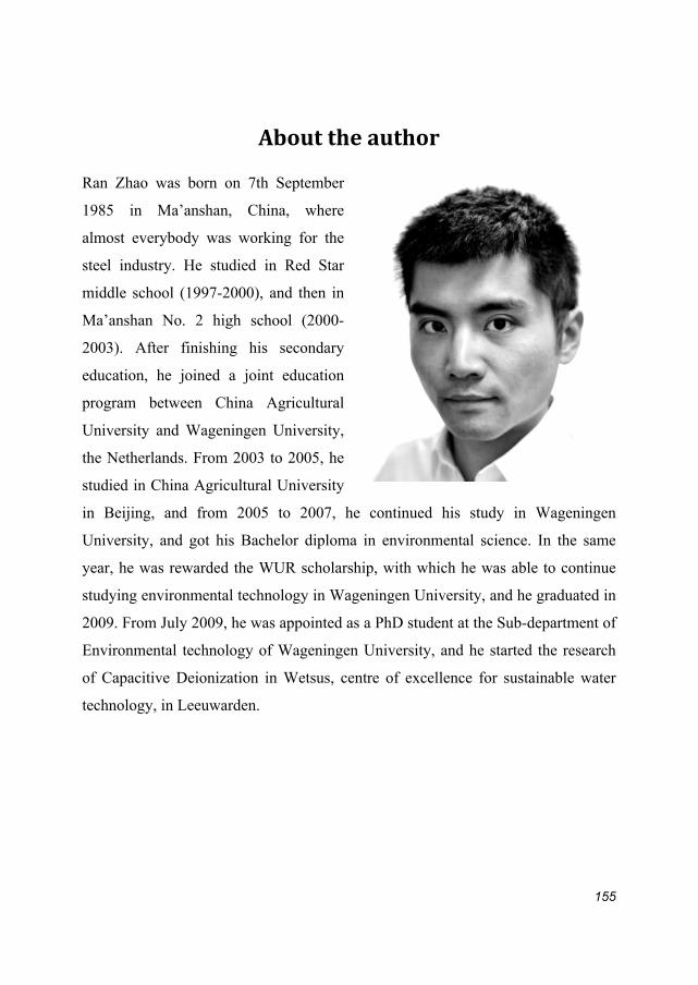
155
Abouttheauthor Ran Zhao was born on 7th September
1985 in Ma’anshan, China, where
almost everybody was working for the
steel industry. He studied in Red Star
middle school (1997-2000), and then in
Ma’anshan No. 2 high school (2000-
2003). After finishing his secondary
education, he joined a joint education
program between China Agricultural
University and Wageningen University,
the Netherlands. From 2003 to 2005, he
studied in China Agricultural University
in Beijing, and from 2005 to 2007, he continued his study in Wageningen
University, and got his Bachelor diploma in environmental science. In the same
year, he was rewarded the WUR scholarship, with which he was able to continue
studying environmental technology in Wageningen University, and he graduated in
2009. From July 2009, he was appointed as a PhD student at the Sub-department of
Environmental technology of Wageningen University, and he started the research
of Capacitive Deionization in Wetsus, centre of excellence for sustainable water
technology, in Leeuwarden.


This work was performed in the TTIW-cooperation framework of Wetsus, Centre
of Excellence for Sustainable Water Technology, Leeuwarden, The Netherlands
(www.wetsus.nl). Wetsus is funded by the Dutch Ministry of Economic Affairs,
the European Union Regional Development Fund, the Province of Fryslân, the City
of Leeuwarden, and the EZ/Kompas program of the “Samenwerkingsverband
Noord-Nederland”. Funding was also provided by the participants of the theme
“Capacitive Deionization”.

Cover designed by Yiwen Chen
Related Documents


