, 0 , ,------ /r3 . I... ---- _ DOCUMENT RESUME ..,. Win-0-5-7-5 ----- - ,... 7; . _TITLE Opticalman 3 and 2, Rate Training Manual. 6 ' APS TITUTION ., \ Bureau of Naval-Personnel, Washington, D. C.; Nay.al a , Personnel Program Support Activity, Washington, D. SE 014 122 REPORT N9 PUB DATE . NOTE ' EDRS PRICE DESCRIPTORS *Equipment Maintenance; Instructional Materials; Machine Tools; Mebhanical Equipment; Military Science; *Military Training; -*Optics; Physics; *Post Secondary Education;- *Supplementary Textbooks C. NAVPERS-10205-A 70 387p. Revised 1970 MF-$0.65 HC-$13.16 ABSTRACT Theories and practical skills for' use in optical shops; are presented in this rate training manual, prepared for regular navy and naval reserve personnel. Light theories are analyzed in connection with mirrors, prisms, lenses, and basic optical . systems. 'Following fund'amentals of mechanical design and construction, maintenance -procedures-are-studied-to gi e'a general . knowledge. optical repair.. Special. descriptions are thde of such instruments as spyglasses, telescopes, magnetic compass s, azimuth and b,earisag -circles, sextants, stadimeters, telescopic álidades, binoculars, subm4kine periscopes, and night vision sights. To give enough background for .readers, operations of lathes, grinders, ,.._ milling machines, and drill presses are also discussed. Besided illustrations for explanation purposesi information on the opticalMara ratingstructure. is also provided. (CC) fr -

Welcome message from author
This document is posted to help you gain knowledge. Please leave a comment to let me know what you think about it! Share it to your friends and learn new things together.
Transcript
, 0, ,------
/r3 .
I...
----_
DOCUMENT RESUME..,.
Win-0-5-7-5 ----- - ,...
7; ._TITLE Opticalman 3 and 2, Rate Training Manual.
6 ' APS TITUTION ., \ Bureau of Naval-Personnel, Washington, D. C.; Nay.ala , Personnel Program Support Activity, Washington, D.
SE 014 122
REPORT N9PUB DATE
. NOTE
' EDRS PRICEDESCRIPTORS *Equipment Maintenance; Instructional Materials;
Machine Tools; Mebhanical Equipment; MilitaryScience; *Military Training; -*Optics; Physics; *PostSecondary Education;- *Supplementary Textbooks
C.NAVPERS-10205-A70387p. Revised 1970
MF-$0.65 HC-$13.16
ABSTRACT Theories and practical skills for' use in opticalshops; are presented in this rate training manual, prepared forregular navy and naval reserve personnel. Light theories are analyzedin connection with mirrors, prisms, lenses, and basic optical .
systems. 'Following fund'amentals of mechanical design andconstruction, maintenance -procedures-are-studied-to gi e'a general .
knowledge. optical repair.. Special. descriptions are thde of suchinstruments as spyglasses, telescopes, magnetic compass s, azimuthand b,earisag -circles, sextants, stadimeters, telescopic álidades,binoculars, subm4kine periscopes, and night vision sights. To giveenough background for .readers, operations of lathes, grinders, ,.._milling machines, and drill presses are also discussed. Besidedillustrations for explanation purposesi information on the opticalMararatingstructure. is also provided. (CC)
fr
-
S PAH rl.it 11 O Olt Allk ()Of:A V111 F APOOF f ICI OF I DUCA 71.04.
C
.
.00 11 -1 fr.,git, ae
"4410
tit4
(
.OPTICALMAN 3 &
BUREAU OF NAVAL PERSONNEL
RATE TRAINING MANUAL NAVPERS 10205 A
Fr
1
PREFACE
This training manual' was. prepared for the Bureau of Naval Personnelby the Training Publications Division, Naval Personnel Program SupportActivity, Washington, D.C. It is intended to serve as an aid for men ofthe U.S. Navy and Naval Reserve who are studying to acquire the theo-retical knowledge and practical skill required for recommendation foradvancement to Opticalman 3 and OpticalmanP2.
Chapter 1 presents information on the enlisted rating structure, theOptfcalman rating, requirements and procedures for advancement, andreferences which will be helpful in studying for advancement. A de-scription of how this text may be used to the best advantage is alsoincluded.
Chapters 2 through' 10 contain information on the thipry-of light,. aswell as the principles of optics and the skills used in optical repair.
The theory of light and optical elements is presented in a manner thatwill giVe the reader a 6.gmplete understanding of how light is controlledand used to produce a magnified image of an object.
Chapters 11 through 14 contain descriptive matter and illustrationssufficient toprovide a general knowledge of the instruments that Optical-man 3rd and 2nd class are required to maintain.
Technical assistance in preparing this manual was provided by theService School Command, Naval Training Center, Great ,Lakes, Illinois;the Naval Examining Center,- Great Lakes,- Illinois; and the Naval ShipSystems Command, Washington, D.C.
First Edition 1966Revised 1970
Stock Ordering No.0500-073-7010
4
For 4utle by the Superintendent of Documents. U.S. Government Printing Office, Washington, D.C. 20402 - Price $3.50 (MOM.- copy).Subscription price: $14.00 per year: $3.50 additional for foreign mailing.
i

THE UNITED STATES NAVY
- GUARDIAN OF OUR COUNTRY'The United States Navy is responsible for maintaining control ofand-is a ready force orywatch at home-and overseas, capable of strongaction to preserve the peace or of instant offensive action to .win in war.
It is upon the maintenance of this control that our country's gloriousfuture depends; the United States Navy exists to make it so.
WE SERVE WITH HONOR
Tradition, valor, and victory are the Navy's heritage from the past. Tothese may be added dedication, discipline, and vigilance as the watchwordsof the present and the future. (
At home or on distant stations we serve with pride, confident in the 'respectof cur country, our shipmates, and our families.
Our responsibilities sober us; our adversities strengthen us.
SerVice to God and Country is our special privilege. We serve with honor.. -/
THE FUTURE OF THE.NAVY
The Navy will always employ, new weapons, new techniques, andgreater power to protect and defend the United Slates on the sea, underthe sea, and in the air.
Now and in the future, control of the sea gives the United States hergreatest advantage for the maintenance of peace and for victory in war.
Mobility, surprise, dispersal, and offensive power are the keynotes ofthe new Navy.. The roots of the Navy lie in a strong .belief in thefuture, in continued dedication to our tels, and in reflection on ourheritage from the past.
Never have our opportunities and our responsibilities been greater.
ii
3

CHAPTEFf
. CONTENTS
1. Advancement
d Prisms
2. The Nature of Light
3. Mirrorsan
4. Lenses
5. Basic Optical Systems
6. Design and Construction
7. Maintenance ProceduresPrt I
8. "Maintenance ProceduresPart II
9. Machine Tool OperationPart I
10. Machine Tool OpeiationPart\II
11. Telescopes
,12. Navigation Instruments
13. Binoculars
14. Submarine Periscopes
15. Night Vision Sights
INDEX
Page
1
8
35
50
94
126
155
185
207
243
274r.
300
336
357
374
380
CREarrs
The illustrations listed below are included in this edition of Optical-man 3 & 2 through the courtesy of the designated companies, publishers,and associations. Permission to reprodget illustrations, and other mate-rials in this publication mutt be obtained from the source..
Source Figures
South Bend Lathe Works ;9-1, 9-2, 9-3, 9-5;9-6, 9-7Y9-10,9-11, .9-12, 9-13, 9-14, 9-15,
Reed-Prentice Corporation
Lodge and Shipley MachineTool Corporation
.
Brown & Sharp Manufacturing.Company
9-16, 9-17, 9-20, 945, 9-26,9-29, .9-31, 9- 32/9 -33, 9-34,9-35, 9 -37, 9-38, 9-39, 9-42,9-43, 9-44, -945, 9-46, 9-47,9-48, 9-50/9-51, '9-52, 9-53,9-54, 1042, 10-36
9494/
10-6, 10-7, 10-8, 10-9, 10-12,10-13, 10-15, 10-16, 10-17,10-20, 10 -21
Cincinnati Milling Mac Co. 10-11, 10-14, 10-22
BaUscie & Lomb Opt$9 Company 13-4,
Cincinnati Bicify:f7dTool Co. 1045
Cleveland Tv ist Drill Co. 10-27, 10-28
American Technical Society 10-30, 10-31
Herheit D. Hall FoundatiOn. 10-33
iv

CHAPTER 1
ADVANCEMENT
This training manual is designed to help youmeet the occupational qualifications for advance-ment to Opticalman Third class a41 OpticalmanSecond Class. Information presedted is based '
on the June 1970 edition of the Manual of Quali-fications for Advancement NavPers 18068-B.
ENLISTED RATING STRUCTURE
OPTICALMAN BILLETS
Opticalmen generally are assigned duty inoptical shops aboard repair ships or\tenders,and stateside or overseas ship repair facilities.
Occasionally, however, they are assigned dutyashore as instructors in Opticalman schools.Some Opticalmen are assigned to recruitingduty; others are assigned to Naval Reservetraining units.
The two main types of ratings in the present / Other duty assignments include the U.S.enlisted rating structure are general ratings / Naval\ Examining Center, Great Lakes, whereand service ratings. / the servicewide advancement examinations are
GENERAL RATINGS identify broad occupa- prepared and scored; the U.S. Navy Trainingtional fields of related' duties and functions. Publications Division, Naval Personnel ProgramSome general-ratings include service iatings; Support Activity, Washington, D.C. (This train-others do not. Both *egular Navy and 'Naval ing manual that you are now .studying was re-Reserve personnel may hold general ratings. vised by a Master Chief Precision Instrument-
SERVICE RATINGS identify subdivisions or man while he was assigned to an instructorspecialties within a general rating. Although billet at Training Publications Division.) Re-service ratings can exist at any petty officer gardless of location, all Opticalmen are assignedlevel, they are most common at the P03 and by the Bureau of Naval. Personnel, Washington,P02 levels. Both Regular Navy and Naval Rez D.C. -serve personnel may hold service ratings. Keep in Mind that the men of your rating
like all other ratings, perform unique and tinportant roles toward the fulfillment of the ove
THE OPTICALMAN RATING .all mission of the Navy. You must, therefoavail yourself to every source and opportu
Opticaimen maintain, repair, and overhaul to improve your skills as an Opticalman.telescopic alidades, azimuth and bearing cir-cles, binoculars, compasses, gunsights, sex-tants, and other optical instruments. This _ Administrative Responsibilitiesincludes inspection, casualty analysis, disas-sembly, repair, replacement or manufacture of At the third or second class level, ptical-parts, cleaning, reassembly, collimation, seal- men generally do not have the responsi ility foring, drying, gassing, and refinishing of surfaces. administering an optical shop; but an Optical-
The Opticalman rating is a general rating man 2 is responsible for prepari casualtyONLYthere are no service ratings. The work analysis inspection sheets for inst ents andof an Opticalman requires a high degree of also for the maintenance of records and, logs inintelligence and mechanical aptitude. Optical the shop. -Opticalmen on duty at th= 3 or 2 levelinstruments are technical in nature, expensive, should therefore observe the wo of Optical-and delicate. For these reasons, just ANYONE men at the first' class and chi f levels, andcannot, perform satisfactorily the work of an learn as much from them as po = sible about theOpticalman. Intelligence is required to under- work of a shop supervisor. his is the onlystand the principles of operation; and mechani- way to develop to the maximu your usefulnesscal aptitude is necessary in order to repair and to the Navy as an Opticalm . Be prepared for-collimate it: greater responsibility when t is assigned to you.
4,
ty
1
OPTICALMAN 3 & -2
Shop safety is something you should alwaysemphpsize. When _using tools and operatingmachines, it is easy-for one to injure himself.This not only causes personal discomfort butresults in a pecuniary loss to the Navy duringabsence from work. Opticalmen should keepthe shop in excellent working shape and hazard-free, and work individually and collectively ina manner which minimizes personal injury.
REWARDS
Some of the rewards of advancement. areeasy to see. You get more pay. Your job as-signments become more interesting and morechallenging. You are regarded with greaterrespect-by officers and enlisted.personnel. Youenjoy the satisfaction of getting ahead in yourchosen Navy career.
But the advantages of advancing are notyours alone. The Navy also profits. Highlytrained personnel are essential to the function-ing of the Navy.. By each advancement, youincrease your value to the Navy in two-ways.First, you become more valuable as a technicalspecialist in your own rating. And second, youbecome more valuable as a person who cantrain others and thus make far-reaching con-tributions to the entire Navy..
HOW TO QUALIFY FOR ADVANCEMENT
What must you do to qualify for advancement?The requirements may change from time totime, but usually you 'must:
1. Have a certain amount of time in yourpresent grade.
'2. Complete the required military and occu-pational training courses, based on trainingmanuals.
3. Demonstrate your ability to perform allthe PRACTICAL requirements for advancementby completing the Record of Practical Factors,NavPers 1414/1.
4. Be recommended by your commandingofficer, after the petty officers and officerssupervising your work have indicated that they
_consider you capable Of performing the dutiesof the next higher rate. .
5. Demonstrate your KNOWLEDGE by Ipass-ing a written examination on (a) military re-quirements and (b) OCCUPATIONAL qualifica-tions.
Some of these general reqUirements may bemodified in certain ways. Figute 1-1 gives a
more detailed view of the requirements for d-vancement of active duty personnel; figuregives this information for inactive dutysonnet.
Remember that the qualifications for d-vancement can change. Check with,your diviSionofficer or training officer to be sure that youknow the most recent qualifications.
Advancement is not automatic. Even thoughyou have met all the requirements, includingpassing the written examinations, you may notbe able to "sew on the crow" or "add a stripe."The number of men in each rate and rating iscontrolled on a Navywide basis. Therefore, thenumber of men who may be advanced is limitedby the number of vacancies that exist. Whenthe number pf men passing the examination ex-ceeds the number of vacancies, some systemmust be used to determine which men may beadvanced and which may not. The system usedis the "final multiple" and is a combination ofthree types of advancement systems.
Merit rating systemPersonnel testing systemLongevity, or seniority, system
The Navy's system (provides credit I r peformance, knowledge, and-se iority, tnd, whileit cannot guarantee that any, o e = on will beadvanced, it does guarantee that en withina particular rating will have equal ancemenopportunity.
The following factors are considere in com-puting the final multiple:
Factor Maximum Credit
Examination score 80Performance factor 50
(Performance evaluation) /Length of service (years x 1) 20Service in pay grade (years x19) 20Medals and awards 15
-^ 185
All of the.above. iniorniation (except the ex-amination score) is submitted to the Naval Ex-amining Center with your examination answersheet. . After grading, the examination scores,for those passing, are added to the other factorsto arrive at the final-multiple. A precedencelist, which is based sin final multiples, is thenprepared fgr h pay grade within eaetrrating.

Chanter 1ADVANCEMENTA
REQUIREMENTS El to E2 E2 to E3#1 E34 #E4 _
to E5t E5-
to E6t E6
to E7t El
to E8
t E8'to E9
SERVICE
4 mos.service
o0411.Him of
6 mos.
as E2.
_
6 mos.
as 1.3
12 mos.
as E424 mos.
as (5.
36 mos.a: (6.
.8 leers
__tlitsat1_,
1111 CI
service-
-40 inas El.8 of 11years
total
service
siloenlisted
411 ES'as El.
10 of 13years
totalservice
must beenlisted.SCHOOL
RecruitTraining.
-.
i:: -:
Class Afor PR3.11T3.PT3.
AME 3.1111 3.
PN 3FTBMT 3.
i'.
*:& Class B:.:.:::
:tVof-.-AMUC,
MNC. t t
:
PRACTICAL
FACTORS
Locallyprepared
check-offs.
'Retard of. Practical Factors,lavPers 414/1, must becompleted for El and all PO advancements.
PERFORMANCE
TEST
Specified ratings must complete
applicable performance tests be-fore taking examinations.
-:.:.
ENLISTED
PERFORMANCE-
EVALUATION
As used by CO
when appall,advancement.
Counts toward performance factor credit in ad-vancemeet multiple.
EXAMINATIONS.
Locally
preparedtests.
bSoleoew
-
Navywide examinations requiredfor all PO advancements.
Navywide,
select's'. board.'
RATE TRAINING
MANUAL IINCLUDMG MILITARY
REQUIREMENTS]
Required for El and all PO advaniementsunless waived because pf school comple
Hot, but need not be rjepeated if identicalcourse has already been completed. See
Hullers 10052 (current edition]. _
_ .
Correspondence
ceases andrecommended
reeding. See
NavFers 10052
_(current Wiliam].
AUTHORIZATIONCommudieg
Officer $ Naval Examining Confer_
All advancements commanding offi er's recommendation.
t 1 year obligated service required for E5 and El; 2 years for E.1, (8 and (9.# Military leadership exam replied for E.4 and E5. . .
** For El to El, NAVEXANCEN exams or locally prepared tests may be used.t t waived for qualified EOD personnel.
Figure 1- 1. Active-duty advanCement reguirements.
3..
O
fi

OPTICALMAN 3 & 2
REOUIREMENTS*- El toE2
E2 toE3
E3 toE4
E4 to
E5
E5 to
E6
E6 to
ElE8 E9
TOTAL TIME
IN GRADE4 mos I mos. 6 mos: 12 mos. 24 mos.
36 mos.
won
total
8 yrs
service
36 mos.
with
.total
11 yrs
service_____.
24 mos.
Wan
rtotal13 yrs
service
TOTAL TRAINING
DUTY IN mini} 14 dayi, 14 days 14 days 14 days 28 days 42 days
,42 days 28 days
. PERFORMANCE
TESTS.. .....,
Specified ratings must complete applicab eperformance tests before taking examinat on
.
DRILL
PARTICIPATIONSatisfactory participation as a member .of a drill unit
in accordance wan BUPERSINST. 5400.42 series.
PRACTICAL FACTORS
(INCLUDING MILITARY
REQUIREMENTS)
Record of Practical Faders. NayPers 1414/1, must be completed. for all advancements.
RATE TRAINING
MANUAL (INCLUDING
MILITARY REQUIRE
MENU)
_ . .
Completion of applicable course or courses must be entered
in. service record.
EXAMINATION
.
r
Standard Exam
. Standard Exam ,reooired for all PO
Advanaments.
Also pass
Military tutorship Examfor E4 and E5.
Standard Exam,
Selection Board.
AUTHORIZATIONCommandiog
Officer
. 'Naval Exaiining Center
.
Recommendation by comialdieg officer filquired for all advancements.
t Active duty periods may be substituted for training duty.
Figure 1-2.Inactive duty advancement requirements.
4
Chapter 1ADVANCEMENT
Advancement authorizations .are then issued,beginning at the top of the list, for the numberof men needed to fill the existing vacancies.
HOW. TO PREPARE FORADVANCEMENT
What must you do to prepare for advance-ment? You must study the qualifications foradvancement, work on the practical factors,study the required Navy Training Manuals, andstudy other material that is required for ad-vancement in your rating. To prepare for ad-vancement, you will need too be familiar with(1) the Qua ls Manual, (2) the Record of PracticalFactors, NavPers 760, (3) a NavPers publica-tion called Training Publications for Advance-ment, NavPers 10052, and (4) applicable NavyTraining Manuals.
The following sections describe them andgive you some practical suggestions on how touse them in preparing for advancement.
The Qua ls Manual
The Manual of Qualifications for Advance-ment, NavPers 18068B (with 'changes), gives theminimum requirements for advancement toeach rate within each rating. This manual isusually called the 'Quals Manual,"and the qual-ifications themselves are often' called "quals."The qualifications are of two general tj'pes:(1) military requirements, and (2) occupationalor technical qualifications.
MILITARY REQUIREMENTS apply ,to allratings rather than to any one particular rating.Military requirements for advancement to thirdclass and second class petty officer rates' dealwith military conduct, naval organization, mili-tary justice, security,watch standing, and othersubjects which are required of petty officers inall ratings.
OCCUPATIONAL QUALIFICATIONS aretechnical or professional requirements that aredirectly related to the work of each rating.
Both the military requirements and the pro-fessional qualifications are divided into subjectmatter groups; then, within each subject mattergroup, they are divided into PRACTICAL FAC-TORS and KNOWLEDGE FACTORS. Practicalfactors are 'dings you must be able to DO.Knowledge factors are things you must KNOWin order to perform the duties of your rating.
The written examination you will take foradvancement will contain questions,relating tothe practical factors and the knowledge factors
of both the military requireffients and the pro-fessional qualifications. If you are working foradvancement to second class, remember thatyou may be examined on third class qualinca-tions as well as on second class qualifications.
The Quals Manual is kept current by meansof changes. The professional qualifications foryour rating which are covered intthis trainingmanual were based on change 5 to the quals..By the time you are studying this .pourde., how-ever., the quals for your rating may have beenchanged. Never trust any set of quals until youhave checked it against an UP -TO -DATE copyin the Quals Manual. .*
.
Record of Practical Factors
Befbre you can lake the servicewide exami- .\nation for advancement in rating, there must bein entry in your service record' to s:-iw thatyou have qualified in the practical factors ofboth the military requirements and the professional qualifications. A,special form-known asthe RECORD OF PRACTICAL FACTORS, Nav=Pere 1414/1, is used to keep a record of yourpractical factor qualifications. This form isavailable for each rating. The form lists allpractical factors, both military and profes-sional. As you demonstrate your ability toperform each practical factor, appropriate en-tries' are made in the DATE and INITIALSzolumns.
Changes are made periodically in the Manual:of Qualifications for Advancement in Rating, andrevised forms of NavPers 1414/1 are providedwhen necessary. Extra space is allowed on theRecord of Practical Factors for entering addi-tional practical fa tors as they are published inthe changes to the uals Manual. The Recordof Practical Factors. so provides space forrecording demonstrated proficiency in skillswhich are within the general scope of the ratingbut which are not identified as minimum quali-fications for advancement.
If you are transferred before you can qualifyin all practical factors, the NavPers 1414/1form should be forwarded with your servicerecord to your next duty station. You can saveyourself a lot of trouble by making sure thatthis form is actually inserted in your servicerecord before you are transferred. If the formis not in,your service record, you may be re-quired to start all over again and requalify inthe practical factors which have alread7 been
i.checked off.0
5
Ael
\
OPTICALMAN 3 &
NavPers 10052
Training Publications for Advancoinent Nav-.Pers 10052 (r.Tvised), is a very important pub-lication for anyone preparing for advancement.,This bibliography lists required and recom-mended Rate Training Manuals, and otherreference material to be used by personnelworking for advancement. NavPers 10052 is
, revised and issued once each year by the -Bu-reau of Naval Personnel. Each revised edition
I is identified by a letter following the NavPers/ number. When using this publication, be SUREthat you have the most recent edition.
If extensive changes, in qualifications occurin any rating between the annual revisions ofNavPers 10052, a supplementary list of studymaterial may be issued in the form of a BuPersNotice. When you are preparing for advance-ment, check' to see whether changes have beenmade in the qualifications for your rating. Ifchanges have been made; see if a BuPers Noticehas been issued to supplement NavPers 10052for your rating.
The required and recommenled referencesare listed by rate level in NavP rs 10052. Ifyou are working for advancement to lid class,study the material that is listed forth class.If you are working for advancement to secondclass, study the material that is listed for sec-ond class; but .remember that you are-alsh-re-sponsible for the references listed at the thirdclass level.
In using Na.iPers 10052, you will notice thatsome 'Navy Training Courses are marked Withan asterisk (*). Any .course marked in this wayis MANDATORYthat is, it must be completedat the indicated 'rate level before you can beeligible to take the servicewide examination foradvancement in rating. Each mandatory coursemaybe completed by (1) passing the appropriateenlisted correspondence cow se that is basedon the training manual; (2) passing locally pre-pared tests based on the information given inthe training manual; or (3) in come cases, suc-cessfully completing an appropriate Class Aschool.
Do not overlook the sections of NavPers10052 which lists the required and recommendedreferences relating to the military require-ments for advancement. Perso,,nel of ALL rat-_----ings must complete the mandatory militaryrequirements training course for the appro-priate rate level before they earlobe eligible toadvance.
C
6
//
The.references in NavPers 10052 which arerek:ominended but not mandatory should also bestudied carefully. All references listed inNavPers 10052 may be used as source materialfor the 'written examinations; at the appropriaterate levels.
Rate Training Manuals
There are two general types of rate trainingmanuals.' The first type includes RATING man-uals (such as this one) which are prepared formost enlisted ratings. A rating manual givesinformation that is directly related to the occu-pational qualifications of ONE rating.- The sec-ond type includes SUBJECT MATTER manualsor BASIC manuals whichl give information thatapplies to mere than one rating.,
Rate training manuals are revised from timeto time to keep them up to date technically.The revision of. a ,rate training manual is is en-tilted b a letter fol4owing the Nar?e,rs number.Yo tell whet,lie`r any particular copy of a.tr ing manual is the latest edition by checkingthe NavPers number and the letter followingthis- numimr.in the most recent edition of Listof Training Manual 8' and CorrespondenceCourses, NavPers 10061. (NavPers 10061 isactually a catalog that list all current trainingmanuals ancfcC&respondence courses; you Willfind this catalog useful' in planning your st-tclyprOgrani.). Rate training manuals are Cvsliim to iiilpyou prepare. for advancement. The followingsuggestions may help you to make the best useof this.course and other Navy training publica-tions when you are preparing for advancement..
1. Study the military qualifications and theoccupational qualifications for your rating be-fore you study the training manual, and referto the quals frequently as you study. Remember,you are studying the manual primarily in orderto meet these quals.
2. Set up a regular study plan. It will prob-ably be easier for you to stick to a schedule ifyou can plan to study at the same time each day.If possible, schedule your studying for the timeof 'day when you will not have too many inter-ruptions or distractions.
Befcire you begin to study any part of themanual intensively, become familiar with theentire book. Read the preface and the table ofcontents. Check through the index. Look at theappendixes. Thumb through the book withoutany particular plan, looking at the illustrations
Chapter 1ADVANCEMENT
and 'reading bits here and there as you see thethings that interest you.
4. Look at the training manual in more detailto see how it is organized.. Look at the table ofcontents again. Then, chapter by chapter, readthe introduction, the headings, and the subhead-ings. This will give you a pretty clear pictureof the scope and content of the book. As youlock through the book in this way, ask yourselfsome questions:
What do I need learn about this?What do I alre y know about this?How is this information related to irs.for-
,mation gieei in other chapters?How is this information related to the
qualifications for advancement?
5. When you have a general idea of what isin the training manual and how is organized,fill in the details by intensive study. In eachstudy period, try to cover a complete unititmay be a chapter, a section of a chapter, or asubsection. The amount of material that youcan cover at one time will vary. If you knowthe subject well, or if the material is easy, youcan cover quite a lot at one time. Difficult orunfamiliar material will require more studyTime.
6. In studying any one unitchapter, section,or subsectionwrite down the questions thatoccur to you. _Many people find it helpful tomake a written outline of the unit as they study,coy at least to write down the most importantideas.
7. As you study, relate the information inthe training manual to the knowledge you al-ready have. When you read about a process,a skill, or I situation, try to see how this in-formation ties in with your own past experience.
8. When you have finished studying the unit,take time out to see what you have learned.Look back over your notes and questions. Maybesome of your questions have been answered,but perhaps you still have some that are not
7
answered. Without looking at the training man-ual, write-clown the main ideas that you havegotten from studying this unit. Don't just quotethe book. If you can't give these ideas in yourown words, chances are that you have not reallymastered the information.
9. Use enlisted correspondence courseswhenever you can. The correspondence coursesare based on rate training manuals or on otherappropriate texts.
Taking a correspondence course helps youto master the information given in the trainingmanual and also helps you to see how much youhave learned.
10. Think of your future as you study ratetraining manuals. You are working for advance-ment to third class or second class right now,but someday 11 be working toward higherrates. Anytliirelixtra that you can learn nowwill help you both now and later.
SOURCES OF INFORMATION
One of the most useful things you can learnabout a subject is how to find out more about it.No single publication can give you all the infor-mation you need to perform the duties of ourrating. You should learn where to look for ac-curate, authoritative, up -to -date informatio onall subjects related to the military requirementsfor advancement and the occupational qualifica-tions of your rating.
Some of the publications described here are.subject to change -orrevision from time totime some at regular intervals, -others as theneed arises. When using any publication thatis subject to change or revision, be sure thatyou have the latest edition. When using. anypublication, that is kept current by means ofchanges, be sure you have a copy in which allofficial changes have been made. Studying can-neled or obsolete information will t help youto do your work or to advance, it is
ntikely to be
a waste of time, and may even be seriouslymisleading.
ti
__ CHAPTER 2
THE NATURE OF LIGHT
Since the dawn of civilization, the real nature. of light and the way it travels has been a con-stant source of intrigue to man. The answer tothe question "What Is Light" has chatted severaltimes in the past 300 years and t this veryday man is still experimenting, looking for thescientific facts that will giie a true answer.
THEORY AND SOURCE OF LIGHT
Since there is no true answer that explainsall of the characteristics of light, we can onlystudy some of the theories of light and the knownfacts of light behavior.
Space in this manual does not permit a dis-cussion on all theories of light, but some ofthem are considered-briefly in order to giveyou an idea concerning their impact on the de-velopment of current theories.
LIGHT THEORIES
Scientists have always been interested in theproperties of light, and because of their inquis-itive minds and experiments, they developedmicas theories concerning light The ancientGreeks, for example, believed that light wasgenerated by streams of particles ejected fromthe eyes, and then reflected back into the eyesby objects ,they struck. This theory did not lastlong bectude it did not explain why a personcould not see as wc:1' by night as by day.
Particles and Waves
In addition to the Greek theory of generatedparticles, Issac Newton believed light to be aflight of material particles originating from asource of light. It was during Newton's timethat Christain Huygens and other physicistsdeveloped the theory that light energy was-aproduct of wave motion. The argument betweensupporters of the particle theory and supportersci the wave theory has continued into our moderntimes.
Corpuscular Theory/
In 1704, Newton published his book called,topTicKir in which he described light as a .
stream of particles he called corpuscles. Fromthis, Newton's theory became known as thecorpuscular theory. One of the'primary argu-ments that supported the particle theory of lightwas the fact that light, traveled in a straightline. Since waves created on water cause adisturbance around an obstacle and sound canbe heard around the corner of a building, pa,rti-cle_supporters would not believe that light wasa wave phenomenon.
Huygens is generally.csmsidlred to be thefounder of the wave- theory. of light, and hisbasic concept is still very useful in predictingthe behavior of light. "Although Huygens' theoryof wave motion appeared to be the logical ex-planation for some phases of light behavior, itwas not accepted for many years. Huygenscould explain the passage of waves through wa-ter, but he did not know how light waves passedthrough space when coming from the sun. Inorder to explain this mystery, he proposed thatlight passed through a medium that occupied allspace which he called ETHER. He assumedthat ETHER even occupied space that was al-ready occupied by matter.
About 50 years after Huygens announced his'theory of wave motion of light, Thomas, Young,Fresuel, and others, supported the wave theory,and Newton's corpuscular theory was virtuallyabandoned. These three scientists accepted theETHER theory and assumed that light waswaves of energy transmitted by an elastic me-dium designated by Huygens as ether.
Electromagnetic Theory
Three other scientists (Boltzmann, Hertz,.and Maxwell) conducted experiments whichproved that light and electricity are similar inradiation and speed. As a result of their ex-periments, they developed the ELECTROMAG-NETIC theory. They produced alternating elec-tric currents with short waveltngths whichwere
8
/5
/Chapter 2 THE NATURE OF LIGHT,
undoubtedly of electromagnetic origin and hadall/the propertiek, of light waves. This theory(sdmetimes called the Maxwell theory) held thatenergy was given off continuously by the radiat-irig body.
For some years after promulgation of theMaxwell .thoory.of light, scientists thought the/puzzle of light was definitely solved. In 1900,/ however, Max Planck rejected the electromag-netic theory. He did not hold the view that en-ergy from a radiating body was given off con-tinuously. His contention was that the radiatingbody contained a large number of tiny oscil-lators, possibly resulting from electrical actionof atoms in the body. His idea was that the en-ergy given off bir the body could be of high fre-quency and have high energy value, with allpossible frequencies represented. Planck ar-gued that the higher the temperature of thradiating body the shorter the wavelength ofmost energetic radiation would be.
Quantum Theory
In order to account for the manner in whichradiation \ fro m a warm, blackbody is distributed'among the different wavelengths, Planck foundan equation to fit the experimental curves, whichwere bafied on lightwaves of different length.He then came to the conclusion that the small
icles of radiated energy were GRAINS ofenergy like grains of sand. He therefore calledthese units quanta and named his theory theQUANTUM THEORY. He assumed that whenquanta wire set free they moved from theirsource in waxes.
Five years later, Albert Einstein backed upPlanck th some complex mathematical equa-tions. H showed that quanta somehow manageto have a equency, like waves. But the quantaare parts es, just the same.
Expert eats by R. A. Miljikan showed thatEinstein's equations were correct. In 1921,A. H. Compton studied the motion of the elec-tron and the light quantum, both before and aftertheir collision. He found that particles of lighthave momentum and kinetic energy, just likeparticles of matter. And that brings us rightback to the corpuscular theory again.
Knowledge gained later by scientists fromthe study of diffraction, interference, polariza-tion, and velocity (explained later) proved thecorpuscular theory of light untenable. Morerecently, however, phenomena of light have beendiscovered which are not accounted for by the
9
wave theory, so many scientists now acceptMaxwell's electromagnetic theory.
Spectroscopy and the birth of the taxer haiegiven scientists valuable tools to experimentwith, and the results of these experiments arecausing scientist to review all previous theoriesof light. Although.not conclusive there is strongevidence to support the belief that light is acombination of the QUANTUM THEORY and theELECTROMAGNETIC THEORY.
In order for a theory concerning light prop-agation to be acceptable, it must prove all thephenomena of light propagation. Since we lacka pronntheory, we have no choice but to acceptthe theory that best explains the passage. oflight through an optical instrument. _This is thewave theory and it will be used for all discus-sions of light in this manual.
SOURCE OF LIGHT
Whether we have previously realized it ornot, all of our lives we have been aware of thegreatest source of light known to man.. This isthe Sun. The sun and all other sources of light,regardless of the amount that they give off, areconsidered to be luminous bodies because theyemit energy in the form of 'visible light. Allluminous bodies are placed in one of two cate-gories, natural or artificial.
Natural
The only sources of natural light are the Sun,which is 93,000.000 miles away, and the stars.Although we receive light from the moon, it ismerely reflected light that comes originallyfrom the Sun.
Artificial
From. the previous statement, it is-easilyunderstood that all light not coming from thesun and stars is artificial light: This coversall light from the first fin. on earth to the mod-ern laser. Man has made many artifibial lightsources since Thomas Edison invented the firstincandescent bulb and with today's neon andfluorescent lights we have a wide variety oLcolors and intensities to choose from.
Illuminated Bodies
Any object that we are able to see, becauseof the light energy reflected from its surface,
st
4
OP4ICALMAN 3 & 2
is called an illuminated body. The moon, be-caise it reflects light from the sun, is in_ illu-minated body. The book that you are nowreading is an illuminated body because it re-flects light energy, whether it is from the sun,a natural source, or an artificial source, suchas fluorescent light fixtures.
Intensity of Illumination
Illumination `can simply" be stated as the actof casting light energy and the intensity of theamount of light energy that is given off is amajor factor in determining how well we areable to see an object. We know very well thatat night when there is little light available it isdifficult to distinguish objects.
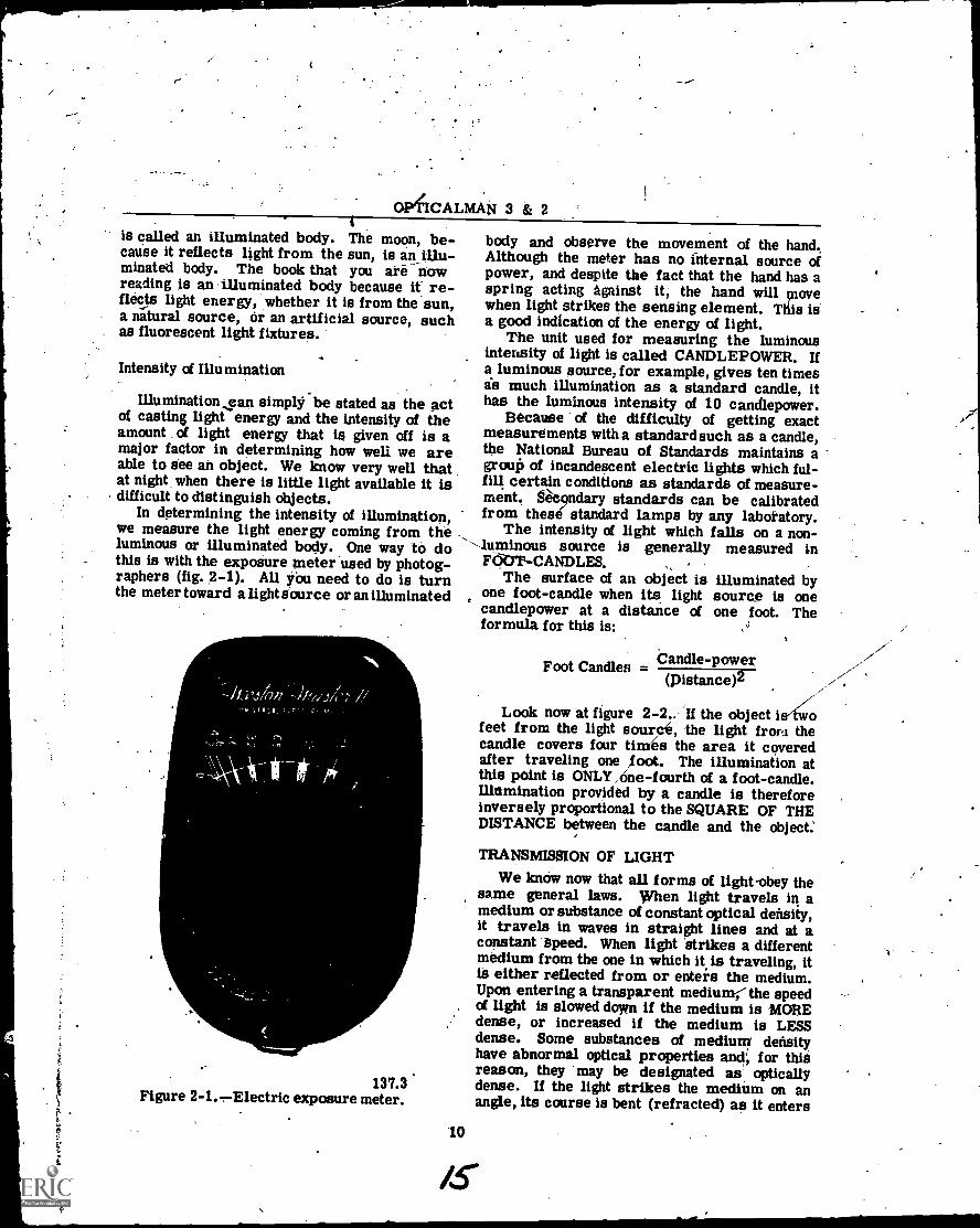
In determining the intensity of illumination,we measure the light energy coming from theluminous or illuminated body. One way to dothis is with the exposure .meter used by photog-raphers (fig. 2-1). AU you need to do is turnthe meter toward a light source oran illuminated
137.3Figure 2-1.Electric exposure meter.
body and observe the movement of the hand.Although the meter has no internal source ofpower, and despite the fact that the hand has aspring acting against it, the hand will vnovewhen light strikes the sensing element. This isa good indication of the energy of light.
The unit used for measuring the luminousintensity of light is called CANDLEPOWER. Ifa luminous source, for example, gives ten timesis much illumination as a standard candle, itha_ s the luminous intensity of 10 candlepower.
Because of the difficulty of getting exactmeasurements with a standard such as a candle,the National Bureau of Standards maintains agrow!) of incandescent electric lights which ful-fill certain conditions as standards of measure-ment. 6&ndary standards can be calibratedfrom these standard lamps by any laboratory.
The intensity of light which falls on a non-.
-luminous source is generally measured inFOB_ 'R- CANDLES.
The surface of an object is illuminated byone foot-candle when its light source is onecandlepower at a distance of one foot. Theformula for this is:
Candle-powerFoot Candles -(pistance)2
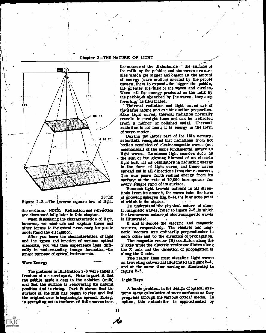
Look now at figure 2-2.. If the object ifeet from the light source, the light from thecandle covers four times the area it coveredafter traveling one loot. The illumination atthis point is ONLY ,6ne-fourth of a foot-candle.Illnmination provided by a candle is thereforeinversely proportional to the SQUARE OF THEDISTANCE between the candle and the object.
TRANSMISSION OF LIGHT
We know now that all forms of light-obey thesame general laws. When light travels in amedium or substance of constant optical density,it travels in waves in straight lines and at aconstant speed. When light 'strikes a differentmedium from the one in which it is traveling, itis either reflected from or enters the medium.Upon entering a transparent medium; the speedof light is slowed down if the medium is MORE
,. dense, or increased if the medium is LESSdense. Some substances of medium densityhave abnormal optical properties and; for thisreason, they may be designated as opticallydense. If the light strikes the medium on anangle, its course is bent (refracted) as it enters
'10
/5
Chapter 2THE NATURE OF LIGHT
1 FT.
2 FT.
1 SO. FT.
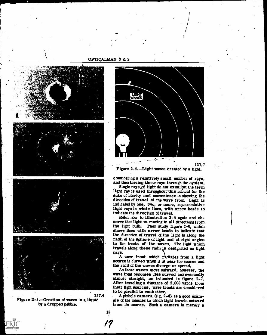
the source of the disturbance .: I the-suilace ofthe milk by the pebble; and the waves are cir-cles which get bigger Lld bigger as the amountof energy (wave motion) created by the pebblecauses them to expandthe bigger the pebble,the greater the/size of the waves and circles..When all thy' energy produced on the milk bythe pebblezia absorbed by the waves, they stopforming(as illustrated.
tfiermal radiation and light waves are of'same nature and exhibit similar properties.
ike light waves, thermal radiation normallytravels in straight lines and can be reflectedfroth a mirror or polished metal. Thermalradiation is not heat; it is energy in the formof wave motion.
During the latter part of the 18th century,scientists ,recognized that radiations 'from hotbodies consisted of electromagnetic waves (notmechanical) of the same fundamental nature aslight waves. Luminous light sources such asthe sun or 'the glowing filament of an electriclight bulb act as oscillators in radiating energyin -the form of light waves, and these wavesspread out in all directions from their sources.The sun pours forth radiant energy from its
e at the rate of 70,000 horsepower forevery t Bare yard of its surface.
1
4 SQ Ft
AA
1
Figure 2 -2. The )verse square-
137:12law of light.
the medium.- NOTE: Reflection.and refriCtionare discussed fully later in this chapter.
When dismissing the characteristics of light,however, we mita ude and explain these andother terms to the extent necessary for you tounderstand the discussion.
After you learn the characteristics of lightand the types and function of various opticalelements, you will then experience less diffi-culty in understanding image formationtheprime purpose of optical instruments.
Wave Energy
The pictures in illustration 2-3 were taken a,fraction of a second apart. Note in part A thatthe pebble made a dent in the solution (milk)and that the surface is recovering its naturalposition and is rising. Part B shows that thesurface ci the milk has begun to rise and thatthe original wave is begbmingto spread. Energyis spreading ad in the form ci little waves from
Because., light travels outward in all direc-tioris from its source, the waves take the formof growing 2-4), the luminous pointof which is the c er.
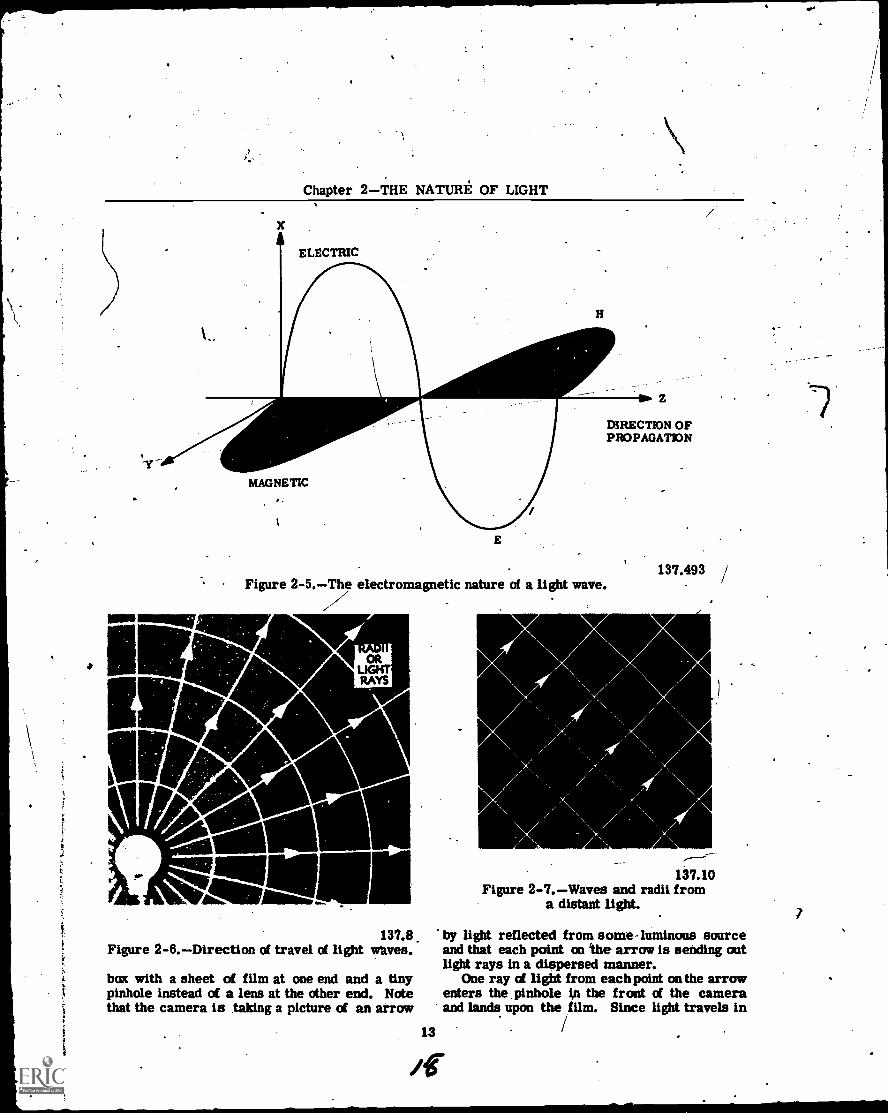
To understand physical nature of elec-tromagnetic wavesi,efer to figure 2-5, in whichthe transverse nature .rif electromagnetic wavesis illustrated.
E and H denote the electric and magneticvectors, respectively. The electric and mag-netic vectors are ordinarily perpendicular toeach other and to the directical of propagation.
The magnetic vector (H) oscillates along theY axis while the electric vector oscillates alongthe X' axle and the direction of propagation isalong the Z axis.
The reader thus must visualize light wavesas traveling outward as illustrated in figure 2-4,and at the same time moving as illustrated infigure 2-5.
11
Light Rays
A basic iroblem in the design of optical sys-tems is the calculation of wave surfaces as theyprogress through the various optical media. Inoptics, this calculation is approximated by
OPTICALMAN 3 & 2
137.4Figure 2-3.Creation of waves in a liquid
by a dropped pebble.
LIGHTV5
137.7Figure 2-4.Light waves created by a light.
considering a relatively small number of rays,and then tracing these rays through the system.
Single rays of light do not exist; but the termlight ray is used thrqughoutthis manual for thesake of clarity and convenience in showing thedirection of travel of the wave front. Light isindicated by one, two, or more, representativelight rays in white lines, with arrow heads to
, indicate the direction of travel.Refer now to illustration 2-4 again and ob-
serve that light is moving in all directions fromthe light bulb. Then study figure 2-6, whiChshows lines with arrow heads to indicate thatthe direction of travel of the light is along theradii of the sphere of light and at right anglesto the fronts of the waves. The light whichtravels along these radii designated as lightrays.
A wave front which r diates from a lightsource is curved when it is near the source andthe radii of the waves diverge or spread.
As these waves move outward, however, thewave front becomes less curved and eventuallyalmost straight, as indicated in figure 2-7.After traveling a distance of 2,000- yards fromtheir light sources, wave fronts are consideredto be parallel to each other.
A pinhole camera (fig. 24) is a good exam-ple of the manner in which light travels outwardfrom its source. Such a camera is merely a
12
/7
Chapter 2THE NATURE OF LIGHT
ELECTRIC
H
11111111111111W
MAGNETIC
E
DIRECTION OFPROPAGATION
Figure 2-5.T,e electromagnetic nature of a light wave.
im-r
ORLIGHTRAYS
137.8Figure 2-6.Direction of travel of light whves.
box with a sheet of film at one end and a tinypinhole instead of a lens at the other end. Notethat the camera is taking a picture of an arrow
137.493 /
137.10Figure 2-7.Waves and radii from
a distant light.
by light reflected from some - luminous sourceand that each point on the arrow is sending outlight rays in a dispersed manner.
One ray of light from each point on the arrowenters the pinhole ip the front of the cameraand lands upon the film. Since light travels in
13

OPTICALMAN 3 & 2
137.11Figure 2-8.Light rays creating an image
on 'the film of a pinhole camera.
straight lines, no light reaches a given point on' -the film except the ray which comes from thecorresponding point on the arrow. The rays oflight which pass through the pinhole of the cam-era form an inverted arrow on the film.
WAVELENGTH AND FREQUENCY
The action of waves on the surface of a liquid(fig. 2-3) helps to understand the wave motion . -of light but in order to understand fully thespeed at which light travels you must compre-hend the length of a wave and its frequency.
A wavelength is the DISTANCE BETWEENthe crest of one wave and the crest of the next(adjacent) wave, as illustrated in figure 2-9.The best way to measure a wavelength is by theFREQUENCYthe number of waves which passa point in one (1) second. You can determinethis by putting a stake in water and counting thenumber of waves which pass the stake per sec-ond. See figure 2-10.
If waves are moving at a speed of 3 feet persecond and have a frequency of 6 waves persecond, you can detefmine the wavelength byusing the formula that shows the relationshipwhich exists between the speed, frequency, andwavelength of light.
The formula is: .
c = f X
c- = speed of light in a 'vacuum,
f = frequency of waves
= (Greek letter "Lambda") wavelength
14
137.14Figure 2-9.Measurement of a wavelength.
137.15Figure 2-10.Determination of wave frequency.
By applying the formula to the above problem,we get
3 = 6X
3/6 =
X = .5
Light waves, in contrast withwaves on water,are much too short to be measured in inches or
M
--Ghapter2=-TilEilAiURE' OF LIGHT
millimetera. (A millimeter is about 1/25th ofan inch. A light wavelength is sometimesmeasured in microns, represented in formulasby g. A micron is one-thousandth of a milli-meter.) For measuring a minute wavelength oflight, a shorter unit than a micron must be used.This unit is the MILLIMICRON, which repre-sents one one thousandth of a micron and isabbreviated mg.
- Another important unit used for measuringwavelengths is thp ANGSTROM UNIT (AU),which is 1/10th of a millimicron, or one ten-millionth of a millimeter. Because these unitsare still inconveniently long for measuring theshortest electromagnetic waves, the X-ray unit(XU) is used for this purpose. It is one one-thousandth of an Angstrom init.
ELECTROMAGNETIC SPECTRUM
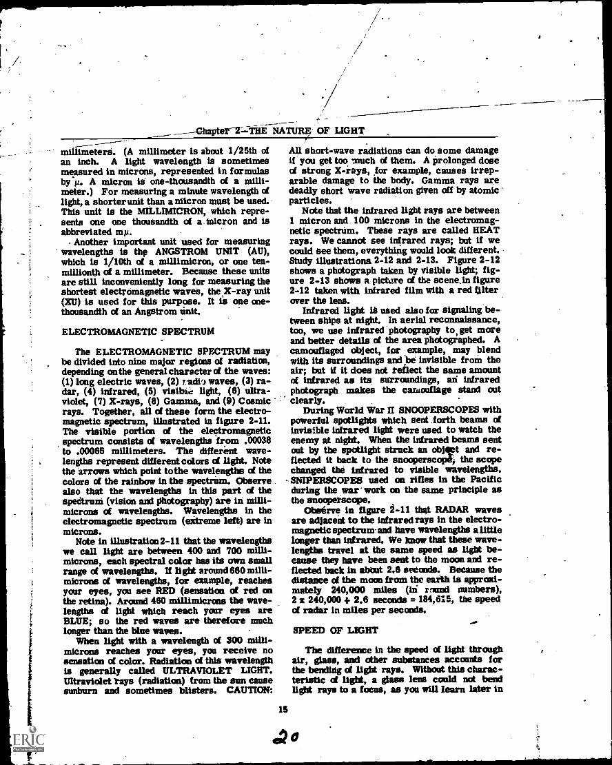
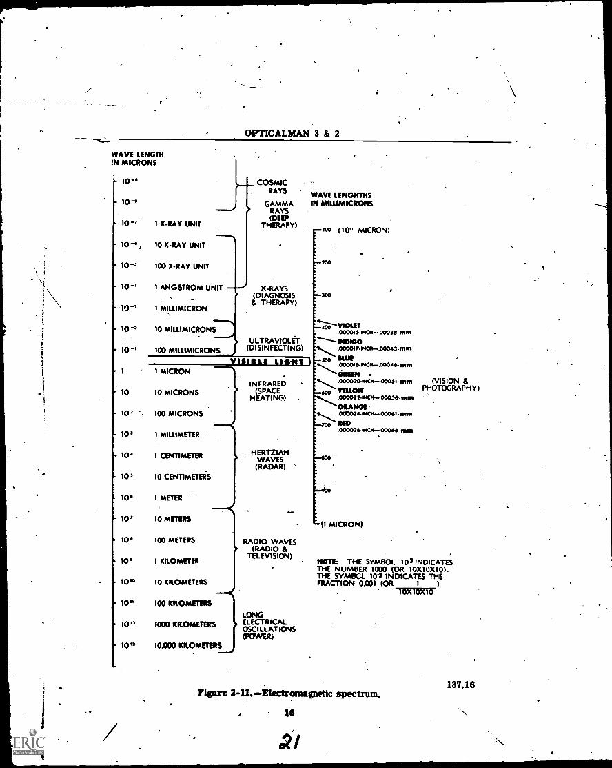
The ELECTROMAGNETIC SPECTRUM maybe divided into nine major regions of radiation,depending on the general character of the waves:(1) long electric waves, (2) 7.dio waves, (3) ra-dar, (4) infrared, (5) visible light, (6) ultra-violet, (7) X-rays, (8) Gamma, and (9) Cosmicrays. Together, all of these form the electro-magnetic spectrum, illustrated in figure 2-11.The visible portion of the electromagneticspectrum consists of wavelengths from .00038to .00066 millimeters. The different wave-lengths represent different colors of light. Notethe arrows which point tothe wavelengths of thecolors of the rainbow in the spectrUm. Observealso that the wavelengths in this part of thespedrum (vision and photography) are in milli-microns of wavelengths. Wavelengths in theelectromagnetic spectrum (eitreme left) are inmicrons.
Note in illustration 2-11 that the wavelengthswe call light are between 400 and 700 milli -microns, each spectral color has its own smallrange of wavelengths. If light around660microns of wavelengths, for example, reachesyour eyes, you see RED (sensation of red onthe retina). Around 460 millimicrons the wave-lengths of light which reach your eyes areBLUE; so the red waves are therefore muchlonger than the blue waves.
When light with a wavelength of 300 milli -microns reaches your eyes, you receive nosensation of color. Radiation of this wavelengthis generally called ULTRAVIOLET LIGHT.Ultraviolet rays (radiation) from the sun causesunburn and sometimes blisters. CAUTION:
15
All short-wave radiations can do some damageif you get too much of them. A prolonged doseof strong X-rays, for example, causes irrep-arable damage to the body. Gamma rays aredeadly short wave radiation given off by atomicparticles.
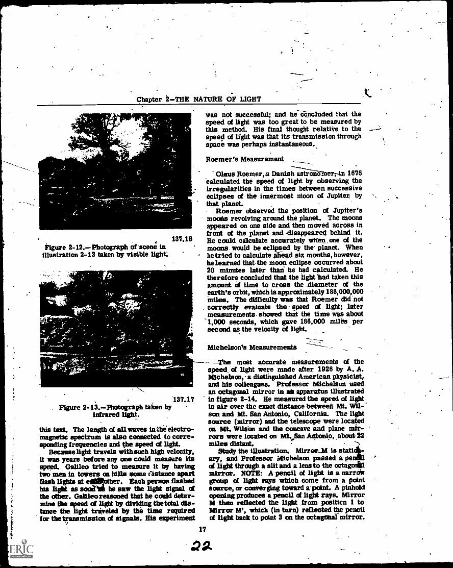
Note that the infrared light rays are between1 micron and 100 microns in the electromag-netic spectrum. These rays are called HEATrays. We cannot see infrared rays; but if wecould See them, everything would look different.Study illustrations 2-12 and 2-13. Figure 2-12shows a photograph taken by visible light; fig-ure 2-13 shows a pictere of the scene in figure2-12 taken with infrared film with a red falterover the lens.
Infrared light ik used also for signaling be-tween ships at night. In aerial reconnaissance,too, we use infrared photography to, get moreand better details of the area photographed. Acamouflaged object, for example, may blendwith its surroundings and be invisible from theair; but if it does not reflect the same amountof infrared as its surroundings, an infraredphotograph makes the camouflage stand outclearly.
During World War II SNOOPERSCOPES withpowerful spotlights which sent .forth beams ofinvisible infrared light were used to watch theenemy at night. When the infrared beams sentout by the spotlight struck an objipt and re-flected it back to the snooperscope, the scopechanged the infrared to visible wavelengths.SNIPERSCOPES used on rifles in the Pacificduring the war' work on the same principle asthe snoopetscope.
Observe in figure 2 -11 that RADAR wavesare adjacent to the infrared rays in the electro-magnetic spectrum- and have wavelengths a littlelonger than infrared. We know that these wave-lengths travel at the same speed as light be-cause they have been sent to the moon and re-flected back in about 2.6 seconds. Because thedistance of the moon from the earth is approxi-mately 240,000 miles (hi round numbers),2 x 240,000 + 2.6 seconds = 184,615, the speedof radar in miles per seconds.
SPEED OF LIGHT
The difference in the speed of light throughair, glass, and other substances accounts forthe bending of light rays. Without this charac-teristic of light, a glass lens could not bendlight rays to a focus, as you will learn later in
el 0
OPTICALMAN 3 & 2
WAVE LENGTHIN MICRONS
10 - COSMICRAYS
WAVE LENGHTHS10" GAMMA IN MILUMICRONS
RAYS(DEEP10 -, 1 X-RAY UNIT THERAPY)
10-*, 10 X-RAY UNIT
10-' 100 X-RAY UNIT
10-4 1 ANGSTROM UNIT
-10-' 1 mILLimICRON
10-' 10 MILLIMICRONS
10-, 100 MILLIMICRONS
1 1 MICRON
.
10 10 MICRONS
10' 100 MICRONS
10' 1 MILLIMETER
10* 1 CENTIMETER
10' 10 .CENTIMETERS
10* 1 METER
10' 10 METERS
10' 100 METERS
10 I KILOMETER
1030 10 KILOMETERS
10" 100 KILOMETERS
10" 1000 KILOMETERS
10'3 10,000 KILOMETERS
X-RAYS(DIAGNOSIS& THERAPY)
100 (10" MICRON)
o~o VIOLET0000154401 00036. mm
ULTRAVIOLET(DISINFECTING) .0000174404 00043.mm
xxj1ILUEo00:4644c1 00016- mm&NEN
INFRARED - s...,.......000020.11,401 00051. men
(SPACE YELLOWHEATING) . 0000224404 00056- mm
ORANGE004024.1,401 00061.mm
RED0000261,401 00066- mm
HERTZIANWAVES(RADAR)
La.
RADIO WAVES(RADIO &
TELEVISION)
LONGELECTRICALOSCIU.ATIONS
OWER)
1 MICRON)
(VISION &PHOTOGRAPHY)
NOTE: THE SYMBOL 103 INDICATESTHE NUMBER 1000 (OR 10X10X10).THE SYMBOL 101 INDICATES THEFRACTION 0.001 (OR 1 ).WO
Figure 2-11.Electromagnetic spectrum.
16
137.16
a
Chapter 2-THE NATURE OF LIGHT
41'
;k" .7-
Figure 2-12.-Photograph of *seen; inillustration 2-13 taken by visible light.
137.18
137.17Figure 2-13.-Photograph taken by
infrared light.
this text. The length of all waves lathe electro-magnetic spectrum is also connected to corre-sponding frequencies and the speed of light.
Because light travels with such high velocity,it was years before any one could measure itsspeed. Galileo tried to measure it by havingtwo men in towers on hills some Cistance apartflash lights at eil0Rother. Each person flashedhis light as s he saw the light signal ofthe other. Galileo reasoned that he could deter-mine the speed of light by dividing the total dis-tance the light traveled by the time requiredfor the transmission of signals. His experiment
17
was not successful; and he e-aincluded that the.speed of light was too great to be measured bythis method. His final thought relative to thespeed of light was that its transmission throughspace was perhaps instantaneous.
Roemer's Measurement
Ohms Roemer,.a Danish astiiii-hto ser-in 1676calculated the speed of light by observing theirregularities in the times between successiveeclipses of the innermost Moon of Jupiter bythat planet.
Roemer observed the position of Jupiter'smoons revolving around the planet. The moonsappeared on one side and then moved across infront of the planet and -disappeared behind it.He could calculate accurately When. one of themoons would be eclipsed by the- planet. Whenhe tried to calculate ahead six months, however,he learned thatthe moon eclipse occurred about20 minutes later than he had calculated. Hetherefore concluded that the light had taken thisamount Of time to cross the diameter of theearth's orbit, which is approximately 186,000,000Miles. The difficulty was that Roemer did notcorrectly evaluate the speed of light; latermeasurements. showed that the time was about1,000 seconds, which gave 186,000 mills persecond as the velocity of light.
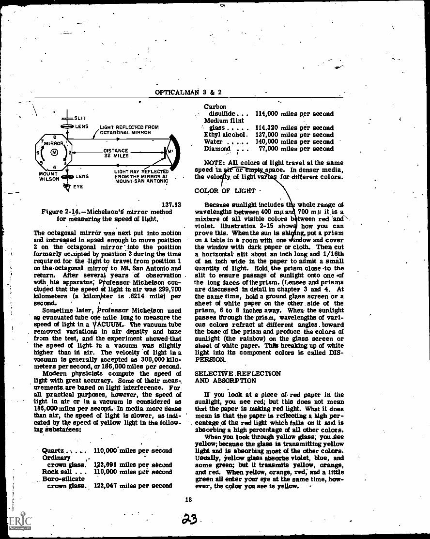
Michelson's Measurements
-The most accurate measurements of theapeed. of light were made after 1926 by A. A.Michelson, a distinguished American physicist,and his colleagues. Professor Michelson usedan octagonal mirror in alt apparatus illustratedin figure 2-14. He measured the speed of lightin air over the exact distance between Mt. Wil-son and Mt. San Antonio, California. The lightsource (mirror) and the telescope were locatedon Mt. Wilton and the concave and plane mir-rors were located on Mt.eSan Antonio, about 22miles distant.
Study the illustration. Mirrer-M is stattary, and Professor Michelson passed a peof light through a slit and a lens to the octagoi1mirror. NOTE: A pencil of light is a narrowgroup of light rays which come from a pointsource, or converging toward a point. A pinholdopening produces a pencil of light rays. MirrorM then reflected the light from positicn 1 toMirror M' which (in turn) reflected the pencilof light back to point 3 on the octagonal-mirror.
OPTICALMAN 3 & 2
SLIT
LENS LIGHT REFLECT-ED FROMOCTAGONAL MIRROR
MOUNTWILSON LENS
EYE
LIGHT RAY REFLECTEDFROM THE MIRROR ATMOUNT SAN ANTONIO
137.13Figure 2-14.Michelson'd mirror method
for measuring the speed of light.
The octagonal mirror was next put into motionand increased in speed enough to move position2 on the octagonal mirror zinto the positionformerly occupied by position 3 during the timerequired for the eight to travel from position 1on the-octagonal mirror to Mt. San Antonio andreturn. After sever years of observationwith his apparatus; P ofessor Michelson con-cluded that the speed light in air was 299,700kilometers (a kilo ter is .6214 mile) persecond.
Sometime later, professor Michelson usedas evacuated tube e mile long to measure thespeed of light in a yAcuum. The vacuum tuberemoved variationis in air density and hazefrom the test, and the experiment showed-thatthe speed of light in a vacuum was slightlyhigher than in air. The velocity of light in avacuum is generally accepted as 300,000 kilo-meters per second, or 186,000 miles per second.
Modern physicists compute the speed oflight with great accuracy. Some of their meas-.urements. are based on light interference. Forall practical purposes, however, the speed oflight in air or in a vacuum is considered as186,000 miles per second.- In media more densethan air, the speed of light is slower, as indi-cated by the speed of yellow light in the follow-ing ettbstatiees:
Quartz . .Ordinary
crown glass.Rock salt . . .Boro-silicate
crown glass.
110,000'miles pier second
122,691 miles per second110,000 miles per second
122,047 miles per second
18
Carbondisulfide . .
Medium flintglass
Ethyl alcoholWaterDiamond .
;
114,000 miles per second
114,320 milea per second137,000 miles per second140,000 miles per second77,000 miles per second
NOTE: All colors of light travel at the samespeed In or space. In denser media,the vel ty. of light var for different colors.
COLOR OF LIGHT
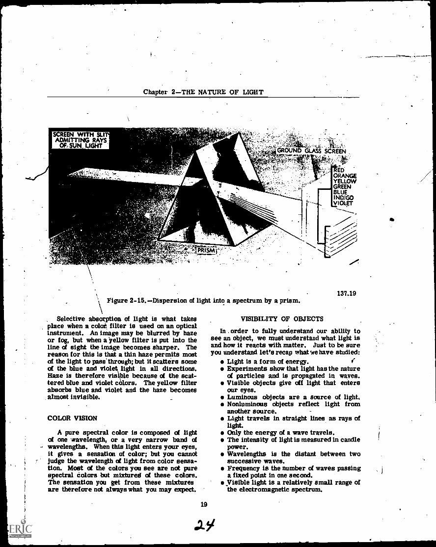
Because sunlight includeswavelengths between 400 mil anmixture of all visible colors bviolet. Illustration 2-15 showprove this. When the sun is son a table in a room with one
whole range of700 mµ it.is atween red 'and''how you cang, put a prismow and cover
the window with dark paper or cloth. Then cuta horizontal slit about an inch long and 1/16thof an inch wide in the paper to admit a smallquantity of light. Hold the prism close -to theslit to ensure passage of sunlight onto one .ofthe long faces of the prism. (Lenses and prismsare discussed in detail in chapter 3 and 4. Atthe same time, hold a ground glass screen or asheet of white paper on the other side of theprism, 6 to 8 inches away. When the sunlightpasses through the prism, wavelengths of vari-ous colors refract at different angles . towardthe base of the prism and produce the colors ofsunlight (the rainbow) on the glass screen orsheet of white paper. Thlt breaking up of whitelight into its component colors is called DIS-PERSION.
SELECTIVE REFLECTIONAND ABSORPTION
If you look at a piece of. red paper in thesunlight, you see red; but this does not meanthat the paper is making red light. What it doesmean is that the paper is reflecting a high per-centage,of the red light which falls on it and isabsorbing a high percentage of all other colors.
When you look through yellow glass, you.eieeyellow; because the glass is transmitting yellowlight and is absorbing most of the other colors.Usually, yellow glass abOorbs "violet, blue, andsome green; but it transmits yellow, orange,and red. When yellow, orange, red; and a littlegreen all enter your eye at the same time, how-ever, the color you see is yellow.
Chapter 2THE NATURE OF LIGHT
REDORANGEYELLOWGREENBLUEINDIGOvioLgT
137.19Figure 2-15.Dispersion of light into a spectrum by a prism.
Seledtive absorption of light is what takesplace when a colot filter is used on an opticalinstrument. An image may be blurred by hazeor fog, but when a yellow filter is put into theline of sight the image becomes sharper. Thereason for this is that a thin haze permits mostof the light to pass' through; but it scatters someof the blue and viole light in all directions.Haze is therefore visible because of the scat-tered Miltered blue and violet c rs. The yellow filterabsorbs blue and violet and the haze becomesalmost invisible.
COLOR VISION
A pure spectral color is composed of lightof one .wavelength, or a very narrow band ofwavelengths. When this light enters your eyes,it gives a sensation of color; but you cannotjudge the wavelength of light from color sensa-tion. Most of the colors you see are not purespectral colors but mixtures of these colors.The sensation you get from these mixturesare therefore not always what you may expect.
19
VISIBILITY OF OBJECTS
In . order to fully understand our ability tosee an object, we must understand what light isand how it reacts with matter. Just to be sureyou understand let's recap what we have studied:
Light is a form of energy.Experiments show that light has the natureof particles and is propagated in waves.Visible objects give off light that entersour eyes.Luminous objects are a source of light.Nonluminous objects reflect light fromanother source.Light travels in straight lines as rays oflight.Only the energy of a wave travels.The intensity of light is measured in candlepower.Wavelengths is the distant between twosuccessive waves.Frequency is the number of waves passinga fixed point in one second.Visible light is a relatively small range ofthe electromagnetic spectrum.
OPTICALMAN 3 & 2
The speed of all electromagnetic waves isthe same in a vacuum.The speed in more dense media is less,and varies with the wavelength.White light is made up, of a mixture ofwavelengths between about 400 and 700millimicrons (mu).When an object reflects some of the wave-lengths of light, but absorb& others, itgives a sensation of color.
We see things. because of reflected light.Objects look different because they reflect lightin a different manner. The difference in "theintensity of light makes a difference inthe visi-bility of an object. Color, likewise, makes adifference in the visibility of objects. If oneobject absorbs twice as much color as motherobject, you have no difficulty in differentiatingbetween them. You can therefore judge the sizeand shape of an object because of the differencein color or intensity of reflected light.
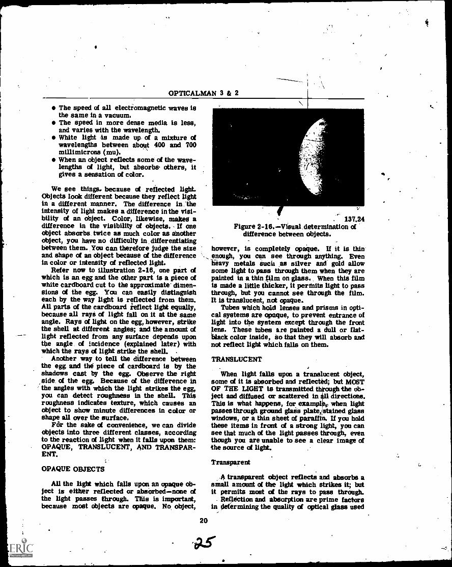
Refer now to illustration 2-16, one part ofwhich is an egg and the other part is a piece ofwhite cardboard cut to the approximate dimen-sions of the egg. You can easily distinguisheach by the way light is reflected from them.All parts of the cardboard ieflect light equally,because all rays of light fall on it at the sameangle. Rays of light on the egg, however, strikethe shell at different angles; and the amount oflight reflected from any surface depends uponthe ang1L of incidence (explained later) withwhich the rays of light strike the shell. .
Another way to tell the difference betweenthe egg and the piece of cardboard is by theshadows cast by the egg. Observe the rightside of the egg. Because of the difference inthe angles with which the light strikes the egg,you can detect roughness in the shell. Thisroughness indicates texture, which causes anobject to show minute differences in color orshape all over the surface.
For the sake of convenience, we can divideobjects into three different classes, accordingto the reaction of light when it falls upon them:OPAQUE, TRANSLUCENT, AND TRANSPAR-ENT.
OPAQUE OBJECTS
All the light which falls upon an opaque ob-ject is either reflected or absorbednone ofthe light passes through. This is important,because most objects are opaque. No object,
20
. 137.24Figure 2-16.Visual determination of
difference between objects.
however, is completely opaque. If it is thinenough, you can see through anything. Evenheavy metals suck as silver and gold allowsome light to pass through them when they arepainted in a thin film on glass.. When this filmis made a little thicker, it permits light to passthrough, but you cannot see through the film.It is translucent, not opaque.
Tubes which hold lenses and prisms in opti-cal systems are opaque, to prevent entrance oflight into the system except through the frontlens. These tubes are painted a dull or flat-black color inside, so that they will absorb andnot reflect light which falls on them.
TRANSLUCENT
When light falls upon a translucent object,some of it is absorbed and reflected; but MOSTOF THE LIGHT is transmitted through the ob-ject and diffused or scattered in ill directions.This is what happens, for exampliec when lightpasses through ground glais plate,Istained glasswindows, or a thin sheet of paraffin. If you holdthese items in front of a strong light, you cansee that much of the light passes through, eventhough you are unable to see a clear image ofthe source of light.
Transparent
.4 transparent object reflects and absorbs asmall amount of the light which strikes it; butit permits most of the rays to pass through.
Reflection and absorption are prime factorsin ylerermining the quality of optical glass used
Chapter 2THE NATURE OF LIGHT
in the manufacture of instruments. This willbe discussed in greater detail later in themanual.
A window pane is a good example of a trans-parent object. Clear glass is considered to betransparent, but the thicker the glass is thegreater the loss of transparency.
REFLECTION
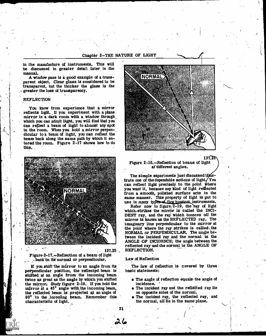
You know from experience that a mirrorreflects light. If you experiment with a planemirror in a dirk room with a window through,which you can adrqit light, you will find that youcan reflect a beam of light to almost any spotin the room. When you hold a mirror perpen-dicular to a beam of light, you can reflect thebeam back along the same path by which it en-tered the room. Figure 2-17 shows how to dothis. .
. - 137.25Figure,2-11.-.ReflectiOn of a beam of light..,backOn its normal or perpendicular.If you shift"the Mirror to an angle from its
perpendicular position, the reflectpd. beam isshifted at an angle from the incoming beamtwice as great as the angle by which you shiftedthe mirror/ Study figure 2-18. If you hold themirror at a 45° angle with the incoming beamthe reflected beam is projected at an angle of90° to the ,incomIng beam. Remember thischaracteristic of light.
21
137.Figure 248.Reflection of beams of light
attlifferent angles.
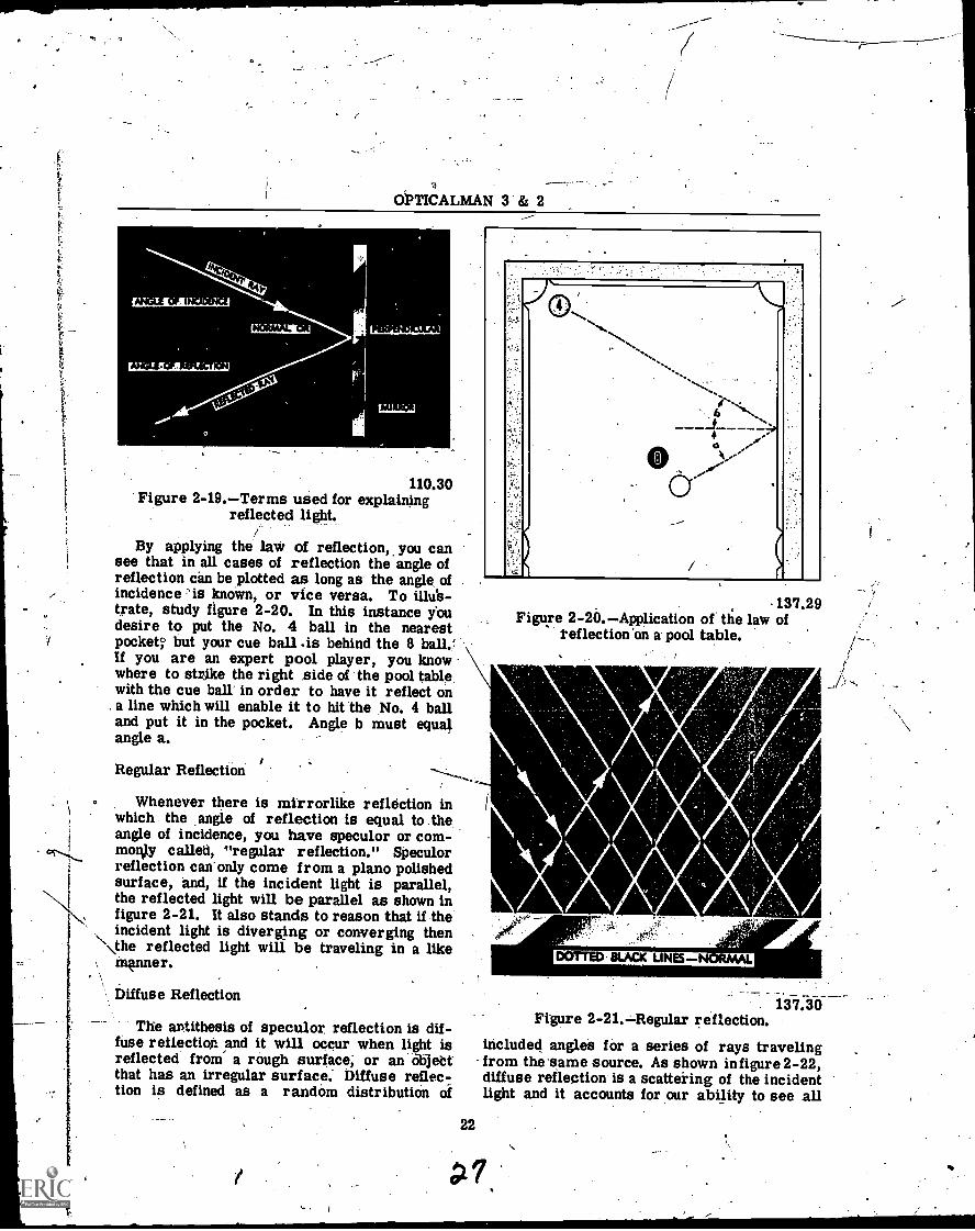
The simple experiments just discussed it s-trate one of the dependable actions of light Youcan reflect light precisely to the point hereyou want it, because any kind of light re ectedfrom a smooth, polished surface acts in thesame manner. This property of light is put touse in many tyg80.41...UrgtgatroLinstruments.
Refer now to figure/2-19, them of lightwhich,strikes the mirrOr is called the INCI-DENT ray, and, the ray', which bounces off themirror is known as the REFLECTED ray. Theimaginary line perpendicular to the mirror atthe point where the ray strikes is called\ theNORMAL or PERPENDICULAR. The angle be-tween the incident ray and the normal is theANGLE OF INCIDENCE; the angle between thereflected ray- and the normal is the ANGLE OFREFLECTION.
Law of Reflection
The law of reflection is covered by threebasic statements:
The angle of reflection equals-the angle ofincidence. *
The incident ray and the reflated ray lieon opposite sides of the normal.The incident ray, the reflected ray, andthe normal, aline in the same plane.
f
-
0
OPTICALMAN 3 & 2
110.30Figure 2-19.Terms used for explaining
reflected light.
By applying the law of reflection, you cansee that in all cases of reflection the angle ofreflection can be plotted as long as the angle ofincidence 'is known, or vice versa. To ilhfs-táte, study figure 2-20. In this instance youdesire to put the No. 4 ball in the nearestpocket but your cue ball .is behind the 8 ball.fIf you are an expert pool player, you knowwhere to strike the right side of the pool tablewith the cue ball' in order to have it reflect on
. a line which will enable it to hit the No. 4 balland put it in the pocket. Angle b must equalangle a.
Regular Reflection
Whenever there is mirrorlike reflection inwhich the ,angle of reflection is equal to theangle of incidence, you have speculor or corn-molly called, "regular reflection." Speculorreflection can only come from a piano polishedsurface, and, if the incident light is parallel,the reflected light will be parallel as shown infigure 2-21. It also stands to reason that if theincident light is diverging or converging then
\\the reflected light will be traveling in a likemkInner.
Diffuse Reflection
The antithesis of speculor reflection is dif-fuse reilection and it will occur when light isreflected from a rough surface; or an objectthat has an irregular surface. Diffuse reflec-tion is defined as a random distribution of
22
IrN1.-
137.29Figure 2-20.Application of the law of
reflection on a' pool table.
V
DOTTED BLACK LINES-
137.3bFigure 2-21.Regular reflection.
included angles for a series of rays travelingfrom the same source. As shown infigure 2-22,diffuse reflection is a scattering of the incidentlight and it accounts for our ability to see all
PI%

Chapter. 2THE NATURE OF LIGHT
. Figure 2:22: Diff
LIGHTRAY
WAVEFRONT
reflection.137.31
nonluminous objects as well as distinguish:shape and texture.. The surface of the paper inthis manual is essentially rough and the lightthat is reflected from it is diffused.
REFRACTION
As yoti study-the meaning of refraction, re-fer to figure 27.23,, whickshows what happens torays of light as they pass through a sheet ofglass. Both plane surfaces of this, glass plateare parallel and air contacts both surfaces.Glass and air are transparent, but the glass is
e-than air; -so light travelsone-third slower in glass than in
optically moreapproxiair.
/Observe the dotted lines (N & N') in the,illustration. These are the aormals erectedfor the incident and refracted rays. When a
. light ray (wave front) strikes the surface of theglass at right angles (parallel to the normal),it is not bent as it passes through the glThis is\ true because each wave iron Tikes
137.32Figure 2-23.Refraction of light beams. by a sheet of glass.
23
1
OPTICALMAN 3 & 2
the surface squarely. The wave front is sloweddown when it strikes the surface of the glass,but it- continues in the same direction it wasgoing before striking the glass. When itsquarely strikes the other surface of the glass,it passes straight through without deviationfrom its course.
If a wave front strikes the first surface ofthe glasS at an angle, as illustrated in part B offigure 2-23, one edge of the first wave frontarrives at the surf:ean instant before theother edge; and thredge which arrives first isslowed down as it enters the denser mediumbefore the second edge enters. Observe thatthe second edge continues to travel at he samespeed, also, until it strikes the stir ce of theglass. This slowing down of one ge .of thewave front' before the other edg slows downcauses the front to PIVOT T WARD THENORMAL.
The information just given relative to a wavefront which strikes' glass plate is applicableFOR ANY FREELY MOVING OBJECT. Whenone side of the object is slowed down as it hitssomething, the other, side continues to move atthe same speed and direction until it also hitssomething. This action causes the object topivot in the direction of the side which hits firstand slow* down. Pivoting or bending- of lightrays (wave fronts) as just explained, is calledREFRACTION; and the bent (pivoted) rays are-labeled REFRACTED RAYS.
U the optical density of a medium (glass inhis case) remains constant, the refracted lightrays continue to travel in* a straight line, asshown in part B of figure 2-23, until the surfacefrom which they emerge (glass-to-air surface)causes interference. At this point, an oppositeeffect occurs to a wave front. As one edge ofthe front reaches the surface (glass-to-air), itleaves the surface.and resumes original speed(186,000 miles per second,' at which it enteredthe glass).
Speeding up of one edge of a wave front' be-fore the other edge speeds up, causes the frontto pivot again; but this time it pivots toward' theedge of the front which has not yet reached thesurface of the glass. Again, THIS BENDING ORPIVOTING OF THE WAVE FRONT IS' CALLEDREFRACTION.
U the glass plate has parallel surfaces, theemergent light ray (ray refracted out of theglass) emerges from the second surface at an'angle equal to the-angle- formed by the incidentray as it entered the glass. If you draw a dotted
24
line along the emergent light ray (fig. 2-23),straight back to the apparent source of the ray,you will find that the emergent ray is parallelto the incident ray.
If the optical density of a medium entered bya light ray (wave front) is constant, the lightfollows its course in a direct line, as illustratedin part B of illustration 2-23.
Laws of Refraction
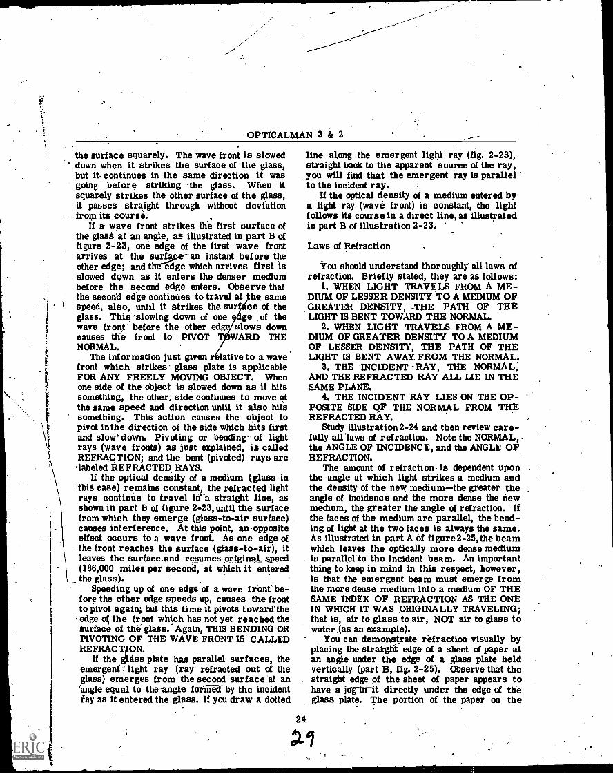
You should understand thoroughly all laws ofrefraction. Briefly stated, they are as follows:
1. WHEN LIGHT TRAVELS FROM A ME-DIUM OF LESSER DENSITY TO A MEDIUM OFGREATER DENSITY, -THE PATH OF THELIGHT IS BENT TOWARD THE NORMAL.
2. WHEN LIGHT TRAVELS FROM A ME-DIUM OF GREATER DENSITY TO A MEDIUMOF LESSER DENSITY, THE PATH OF THELIGHT IS BENT AWAY. FROM THE NORMAL.
3. THE INCIDENT -RAY, THE NORMAL,AND THE REFRACTED RAY ALL LIE IN THESAME PLANE.
4. THE INCIDENT RAY LIES ON THE OP-POSITE SIDE OF THE NORMAL FROM THEREFRACTED RAY.
Study illustration 2-24 and then review care-fully alrlaws of refraction. Note the NORMAL,the ANGLE OF INCIDENCE, and the ANGLE OFREFRACTION.
The amount of refraction is dependent uponthe angle at which light strikes a medium andthe density of the new mediumthe greater theangle of incidence and the more dense the newmedium, the greater the angle of refraction. Ifthe faces of the medium are parallel, the bend-ing of light at the two faces is always the same.As illustrated in part A of figure2-25, the beamwhich leaves the optically more dense mediumis parallel to the incident beam. An importantthing to keep in mind in this respect, however,is that the emergent, beam must emerge fromthe more dense medium into a medium OF THESAME INDEX OF REFRACTION AS THE ONEIN WHICH IT WAS ORIGINALLY TRAVELING;that is, air to glass to air, NOT air to glass towater (as an example).
You can demonstrate refraction visually byplacing the stra}ghl edge of a sheet of paper atan angle under the edge of a glass plate heldvertically (part B, fig. 2-25). Observe that thestraight edge of the sheet of paper appears tohave a joglh-it directly under the edge of theglass plate. The portion of the paper on the
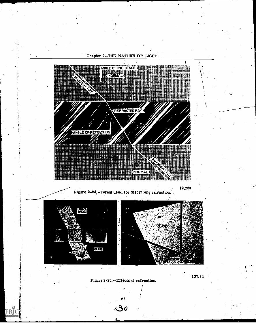
Chapter 2THE NATURE OF LIGHTs
1e,
ANGLE OF I NCIDE .1.sijarE"; .i ',.r.11-1J:idriiiril;:114;i111'iliiiith:ittli'lvIt'.1.L:::::111411:1,,r
NORMAL -1
' lhl If
i 'ti F 4i11;'1 414 FT'
'il .1,; .; i.
t
i
l ;'
ib,. i. H.,:. .1 . .
. .. ; .
104c0 ; l:
' 11 Ti. Ji :lilit'Yll r
1 till to 1.
,t,;:,i ; 1 il .1 J it 3111111
'''.45... 1
1 I1 11 iiii:,11 '
I 11ii 14 111111i
1 i i li jet i till
ANGLE OF REFRACTION
REFRACTED RAY
A
t<%A,-)0NORMAL '44
t t
I iiil II,Lut
12.233Figure 2-24.Terms used for describing refraction. .
'I
PAPER.
Figure 2-25.Effects of refraction.
25
f50
137.34
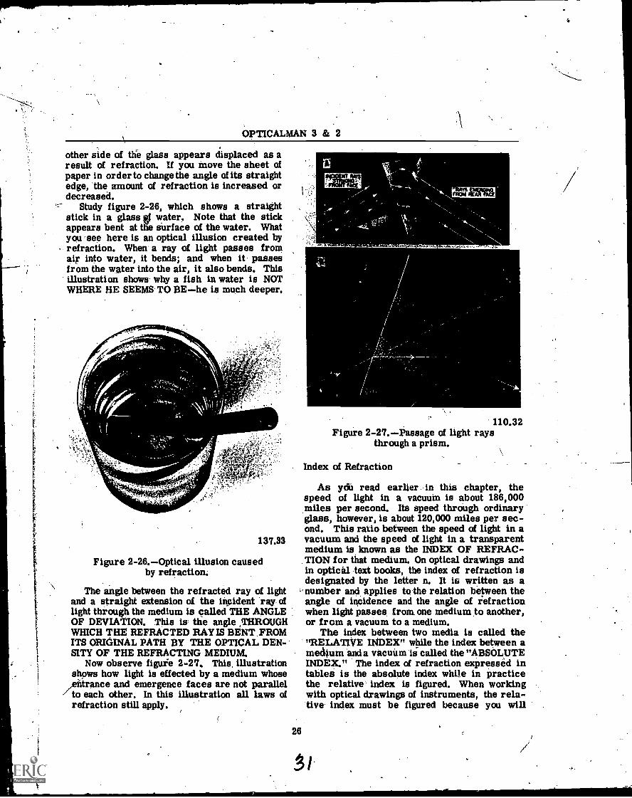
OPTICALMAN 3 & 2
other side of the glass appears displaced as aresult of refraction. If you move the sheet ofpaper in order to change the angle of its straightedge, the amount of refraction is increased ordecreased.
Study figure 2-26, which shows a straightstick in a glass tf water. Note that the stickappears bent at the surface of the water. Whatyou see here is an optical illusion created byrefraction. When a ray of light passes fromaip into water, it bends; and when it passesfrom the water into the air, it also bends. Thisillustration shows- why a fish in water is NOTWHERE HE SEEMS TO BEhe is much deeper.
137.33
Figure 2-26.Optical illusion causedby refraction:
The angle between the refracted ray of lightand a straight extension of the incident "ray oflight through the medium is called THE ANGLEOF DEVIATION. This is the angle ,THROUGHWHICH THE REFRACTED RAY IS BENT _FROMITS ORIGINAL PATH BY THE OPTICAL DEN-SITY OF THE REFRACTING MEDIUM.
Now observe figuie 2-27. This, illustrationshows how light is effected by a medium whose
,efitrance and emergence faces are not parallel-7 to each other. In this illustration all laws of
refraction still apply.
26
110.32Figure 2-27.Passage of light rays
through a prism.
Index of Refraction
As yai read earlier in this chapter, thespeed of light in a vacuum is about 186,000miles per second. Its speed through ordinaryglass, however, is about 120,000 miles per sec-ond. This ratio between the speed of light in avacuum and the speed of light in a transparentmedium is known as the INDEX OF REFRAC-TION for that medium. On optical drawings andin optical text books, the index of refraction isdesignated by the letter n. It is written as anumber and applies to the relation between theangle of incidence and the angle of refractionwhen light passes from one medium to another,or from a vacuum to a medium.
The index between two media is called the"RELATIVE INDEX" while the index between amedium and a vacuum Is called the "ABSOLUTEINDEX." The index of refraction expressed intables is the absolute index while in practicethe relative index is figured. When workingwith optical drawings of instruments, the rela-tive index must be figured because you will
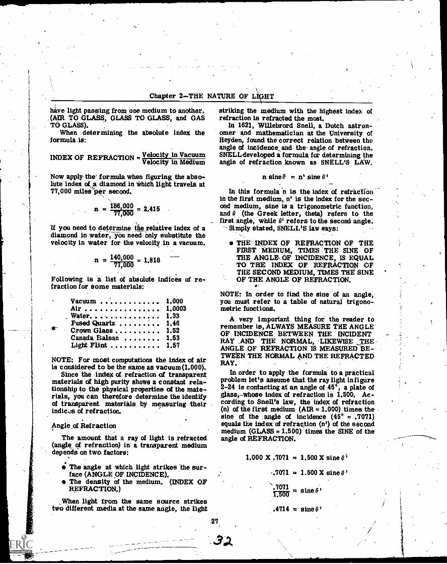
Chapter 2-THE NATURE OF LIGHT
have light passing from one medium to another.(AIR TO GLASS, GLASS TO GLASS, and GAS
. TO GLASS).When determining the absolute index the
formula is:
INDEX OF REFRACTION - Velocity in VacuumVelocity in Medium
Now applythe. formula when figuring the abso-lute index of diamond in *hidi light travels at77,000 miles per second.
n 186,00077,000
2'415
If you need to determine the relative index of adiamond in water, you need only substitute thevelocity in water for the velocity in a vacuum.
140,000 1.81877,000
Following is a list of absolute indices of re-fraction for some materials:
Vacuum 1.000Air 1.0003
_ Water 1.33Fused Quartz 1.46Crown Glass 1.52Canada Balsan 1.53Light Flint 1.57
NOTE: For most computations the index of airis considered to be the same as vacuum (1.000).
Since the .indeA of . refraction of transparentmaterials of high purity shows a constant rela-tionship to the physical properties of the mate-rials, you can therefore determine the identifyof transparent materials by measuring theirindices of refraction.
Angle of Refraction
The amount that a ray of light is refracted(angle of refraction) in a transparent mediumdepends on two factors:
The angle at which light strikes the sur-face (ANGLE OF INCIDENCE).The density of the medium. (INDEX OFREFRACTION.)
When light from the same source strikestwo different media at the same angle, the light
striking the medium with the highest index ofrefraction is refracted the most.
In 1621, Willebrord Snell, a Dutch astron-omer and mathematician at the University ofHeyden, found the correct relation between theangle of incidence_and the angle of refraction..SNELL developed a formula for determining theangle of refraction known as SNELL'S LAW.
27,
n sine0 = n' sine 0'
In this formula 'n is the index of refradtionin the first medium, n' is the index for the sec-ond medium, sine is a trigonometric function,and 0 (the Greek letter, theta) refers to thefirst angle, while 0' refers to the- second angle.
Simply stated, SNELL'S law says:
THE INDEX OF REFRACTION OF THEFIRST MEDIUM, TIMES THE SINE OFTHE ANGLE\ OF INCIDENCE, IS EQUALTO THE INDEX OF REFRACTION OFTHE SECOND MEDIUM, TIMES THE SINEOF THE ANGLE OF REFRACTION.
tr
NOTE: In order to find the sine of an angle,you must refer to a table of natural trigono-metric functions.
A very important thing for the reader toremember is, ALWAYS MEASURE THE ANGLEOF INCIDENCE BETWEEN THE INCIDENTRAY AND THE NORMAL, 'LIKEWISE THEANGLE OF REFRACTION IS MEASURED BE-TWEEN THE NORMAL AND THE REFRACTEDRAY.
In order to apply the formula to a practicalproblem let's assume that the ray light infigure2-24 is contacting at an angle of 45°, a plate oflassy-whose index of refraction is 1.500. Ac-cording to Snell's law, the index of refraction(n) of the first medium (AIR = 1.000) times thesine of the angle of incidence (45° = .7071)equals the index of refrac,tion (n') of the secondmedium (GLASS. = 1.500) times the SINE of theangle of REFRACTION.
1.000 X .7071 = 1.500 X sine 01
.7071 = 1.500 X sine 0
's.7071 sine B'1.500
.4714 = sine B'
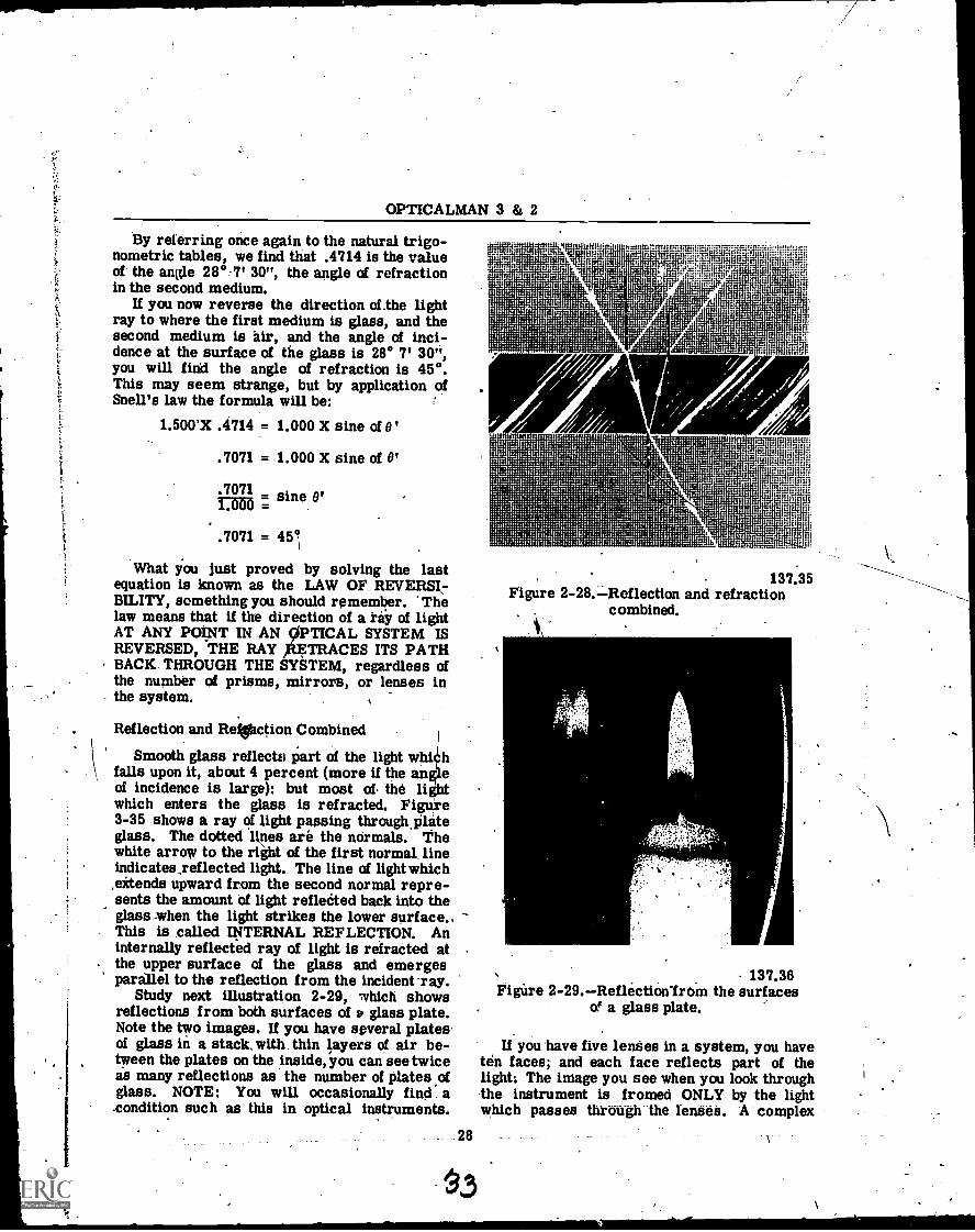
OPTICALMAN 3 & 2
By referring once again to the natural trigo-nometric tables, we find that .4714 is the valueof the angle 28°-7' 30", the angle of refractionin the second medium.
If you now reverse the direction of .the lightray to where the first medium is glass, and thesecond medium is air, and the angle of inci-dence at the surface of the glass is 28° 7' 30",you will find the angle of refraction is 45°.This may seem strange, but by application ofSnell's law the formula will be:
1.500'X .4714 = 1.000 X sine of 0'
. 7071 = 1.000 X sine of IP
. 7071 sine 0'1.000 =
. 7071 = 45°
What you just proved by solving the lastequation is known as the LAW OF REVERSIBILITY, something you should remember. 'Thelaw means that if the direction of a ray of lightAT ANY POINT. IN AN cliPTICAL SYSTEM ISREVERSED, THE RAY laETRACES ITS PATHBACK THROUGH THE SYSTEM, regardless ofthe number of prisms, mirrors, or lenses inthe system.
Reflection and RefSliction Combined
Smooth glass reflecto part of the light whi hfalls upon it, about 4 percent (more if the an eof incidence is large): but most of the liwhich enters the glass is refracted. Figure3-35 shows a ray of light passing through. plateglass. The dotted l &nes are the normals. Thewhite arrow to the right of the first normal, lineindicates,reflected light. The line of light which,extends upward from the second normal repre-sents the amount of light relleeted back into theglass -when the light strikes the lower surface.,This is called INTERNAL REFLECTION. Aninternally reflected ray of light is refracted atthe upper surface of the glass and emergesparailel to the reflection from the incident-ray.
Study next illustration 2-29, which showsreflections from both surfaces of v glass plate.Note the two images. If you have several platesof glass in a stack, with thin layers of air be-tween the plates on the inside, you can see twiceas many reflections as the number of plates ofglass. NOTE: You will occasionally find a.condition such as this in optical instruments.
28-
137.35Figure 2-28.-:-Reflection and refraction
combined.r,
137.36Figure 2-29.Reflectionlrom the surfaces
of a glass plate.
If you have five lenses in a system, you haveten faces; and each face reflects part of thelight: The image you see when you look throughthe instrument is fromed ONLY by the lightwhich passes --through lhe lenses. A complex
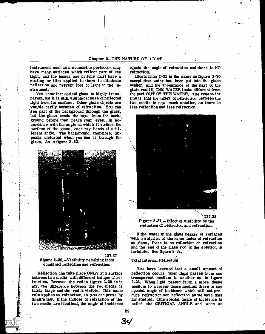
e
Chapter 2THE NATURE OF LIGHT
instrument such as a submarine periscope mayhave many surfaces which reflect part of thelight, and the lenses and prisms must have acoating or film applied to them to eliminatereflection and prevent loss of light in the in-strument.
You know that optical glass is highly trans-parent, but it is still visiblebecause of reflectedlight from its surface. Other glass objects are
\ visible partly because of refraction. You can'see part of the background through the glass,but the -glass bends the rays from the back-ground before they reach your eyes.. In ac -\
cordance with the angle at which it strikes the \surface of the glass, each ray bends at a dif-ferent angle.. The background, therefore, ap-pears distorted when you see it through theglass. As in figure 2-30.
137.37Figure 2-30.Visibility resulting from
combined reflection and refraction.
Reflection can take placeONLY at a surfacebetween two media with different indices of re-fraction. Because the rod in figure 2-30 is inair, the difference between the two- media isfairly large and the rod is visible. This samerule applies to refraction, as you can prove bySnell's law. If the indices of refraction of thetwo media are identical, the angle of incidence
equals the angle of refraction and there is NOrefraction.
Illustration 2-31 is the same as figure 2-30except that water has been put into the glassbeaker, and the appearance the part of theglass rod IN THE WATER looks different fromthe part OUT OF THE WATER. The reason forthis is that the index of refraction between thetwo media is now much smaller, so there isless reflection and less refraction.
137.38Figure 2-31.Effect of visibility by thereduction of reflection and refraction.
If the water in the glass beaker is replacedwith a solution of the same index of refractionas glass, there is no reflection or refractionand the end of the glass rod in the solution isinvisible. See figure 2-32.
Total Internal Reflecticin
You have learned that a small amount ofreflection occurs when light passes from onetransparent medium to another as in figure2-28. When light passeF Let= a more densemedium to a lesser dense medium there is onespecial angle of incidence which will not pro-duce refraction nor reflection as we have thusfar studied. This special angle of incidence iscalled the CRITICAL ANGLE and when an
29
34/
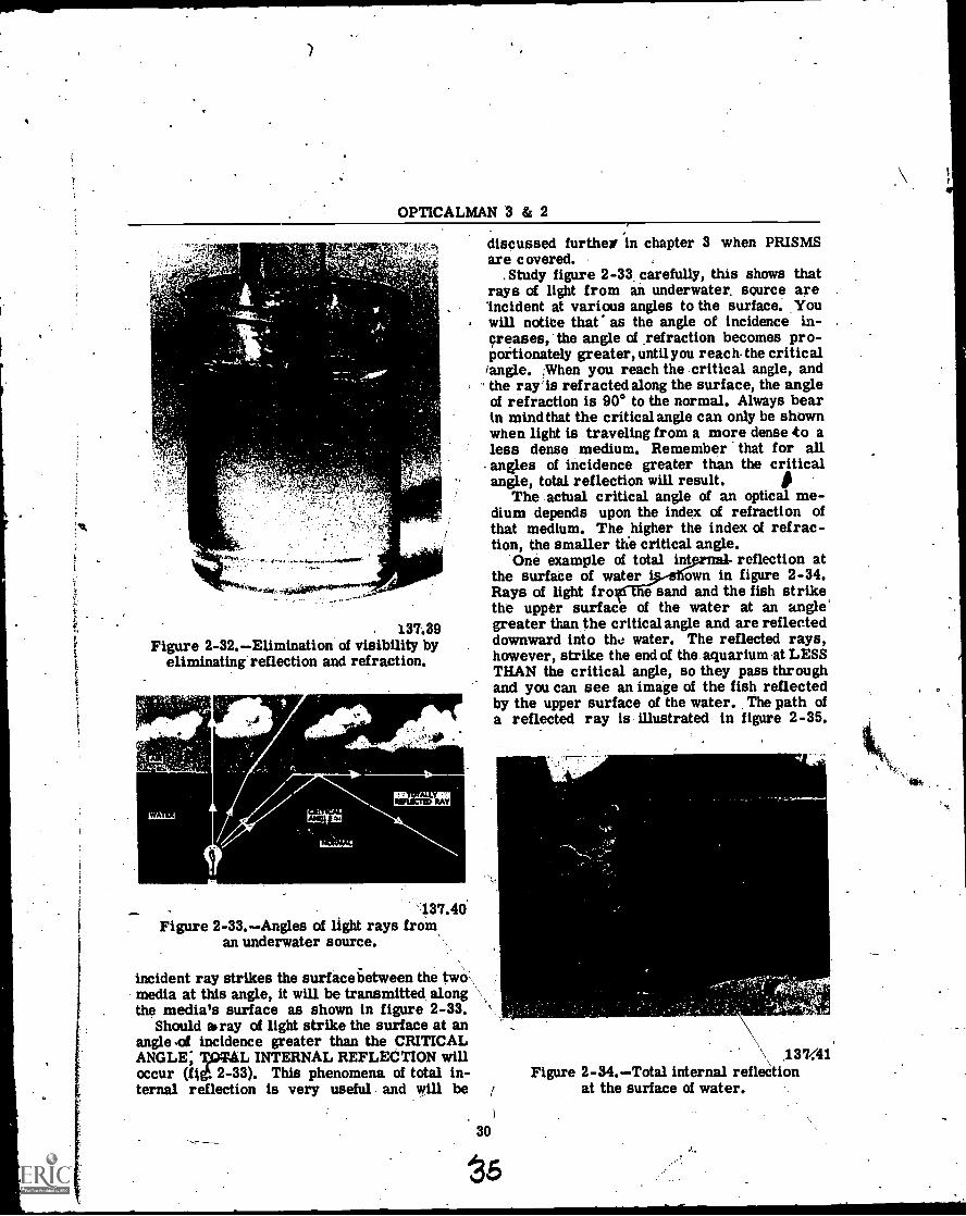
OPTICALMAN 3 & 2
:
137.39Figure 2-32.Elimination of visibility by
eliminating reflection and refraction.
.40
,11111.1CFID AY
137.40Figure 2-33.Angles of light rays from,
an underwater source.
incident ray strikes the surface 6etween the two,,media at this angle, it will be transmitted alongthe media's surface as shown in figure 2-33.
Should bray of light strike the surface at anangle of incidence greater than the CRITICALANGLE; TOTAL INTERNAL REFLECTION willoccur (fit 2-33). This phenomena of total in-ternal reflection is very useful and will be
discussed furthe in chapter 3 when PRISMSare covered.
.Study figure 2-33, carefully, this shows thatrays of light from an underwater, source are'incident at various angles to the surface. Youwill notice that as the angle of incidence in-creases, the angle of _refraction becomes pro-portionately greater, until you reach. the critical/angle. When you reach the critical angle, andthe ray. is refracted along the surface, the angleof refraction is 90° to the normal. Always bearin mind that the critical angle can only be shownwhen light is traveling from a more dense to aless dense medium. Remember that for allangles of incidence greater than the criticalangle, total reflection will result.
30
The actual critical angle of an optical me-dium depends upon the index of refraction ofthat medium. The higher the index of refrac-tion, the smaller the critical angle.
the surface of water i own in figure 2-34.Rays of light fro e sand and the fish strike
One example of total int reflection at
the upper surface of the water at an angle'greater than the critical angle and are reflecteddownward into the water. The reflected rays,however, strike the end of the aquarium at LESSTHAN the critical angle, so they pass throughand you can see an image of the fish reflectedby the upper surface of the water. The path ofa reflected ray is illustrated in figure 2-35.
4'
\ 1.3741Figure 2-34.Total internal reflection
at the surface of water.
S,

Chapter 2THE .NATURE OF LIGHT
Figtire 2-35.Effect of total
Suppose you desire to calculate the criticalangle of a medlual when the other medium isair. How can you do this? Use water as onemedium, as an example, and air as another;then make proper substitutions 'in the formula(Snell's law) and solve the equation. The indexof refraction of water is 1.333; when the angleof incidence .is the critical angle, the'angle ofrefraction is 90 degrees. The procedure forSolving the problem-follows:
/ Snell's law: n sine -0 = n' sine 0
1,333 sine 0 = 1.000 sine 90°
1.000 x 1.000 1.000sine 0 --1.3331,333
sine 0 = .750817
= 48° 36' -
Critical angles for various substances (whenthe external ;aedium is air) are as follows:
Water 48° 36'Crown glass 41° 18'
40° 22'Flint glass 37° 34'Diamond, 24° 26'
137.42internal reflectioq,on light rays".------
The small critical angle of a diamond ac -.counts for its ,brilliance, provided it is a well-cut diamond. The brilliance is due to totalinternal reflection of light; the light is reflected
31
34
back and fo many times before it emerges toproduce b ght, multiplgreflections.
ATMOSPHERIC REFRACTIOW-----
At a surface which separiles two media ofdifferent indices of refraction, the direction ofthe path of light changes abruptly when it passesthrough, the surface. If the index of refractionof a single medium changes uadually as thelight proceeds from point to point, the path oflight also changes 'gradually and is curved.
Although When air is most ifinse it has arefractive index of only 1,000292, the indexsufficient to bend light rays from the sun towardthe earth when these rays strike the atmosphereat an angle.
The earth's atmosphere is a medium whichbecomes more dense towardifie surface of theearth. As a result, a ray of light travelingthrough the atmosphere toward_theearth at anangle does not travel in .a straight line but is..refracted and follows a curved path., Froiipoints near the horizon, in fact, the 'bending oflight is so great that the setting sun is visibleeven after it is below the horizon (fig. 2-36).
Mirages
Over large areas of heated sand or waterthere are layers of air which differ greatly intemperature and refractive indices.__Under suchconditions, erect or inverted (sometinies muchdigtorted) images are formed which are visible
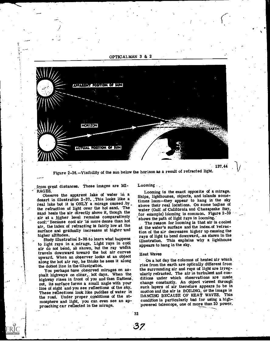
OPTICALMAN 3 & 2
HORIZON
A ON SUN
'
EARTH
137.44 /Figure 2-36.Visibility of the sun below the horizon as a result of refracted light.
_from great distances. These images are MI-RAGES.
Observe the apparent lake of water in adesprt in illustration 2-37. _This looks Like areal lake but it is ONLY a- mirage caused .bythe refraction of light over the hot sand. Thesand heats the air directly above it, though theair at a higher level remains comparativelycoot,- Because cool air is more dense than hotair, the index of refracting is fairly low at thesurface and gradually increases at higher 'andhigher altitudes.
Study illustration 2-38.to learn what happensto light rays in a, mirage. Light rays in coolair do not bend, as shown, but the ray whithtravels downward toward the hot air curvesupward. When an observer looks at an objectalong the hot air ray, he thinks he sees it alongthe dotted line in the illustration.
You perhaps have observed mirages on as-phalt highways on clear,_ hot days. When thehighway rises in front of you and then flattens,out, its surface forms a small angle with yourline of sight and you see reflections of the sky.These reflections look like puddles of water inthe road. Under proper conditions of the at-mosphere and light, you can- even see an ap-proaching car reflected in the mirage.
'32
Looming .
Looming is the exact opposite of a mirage.Ships, lighthouses, objects, and islands some-times loomthey appear to hang in the skyabove their real locations. On some bodies ofwater (Gulf -of California and Chesapeake Bay,for example) looming is common. Figure 2-39shows the path of light rays in looming.'
. The reason for looming is that air is cooledat the water's surface and the index,of refrac-tion of the air decreases higher up causing therays of light to bend downward,_as shown in theillustration. This explains why a lighthouseappears to hang in the sky.
Heat WaiesOn a hot day the columns of heated air which
rise from the earth are optically different fromthe surrounding air and rays of light are irreg-ularly refracted. The air is turbulent and con-ditions under which observations are madechange constantly. An object viewed throughsuch layers of air therefore appears to be inmotion and the air is BOILING, or the image isDANCING BECAUSE OF HEAT WAVES. Thiscondition is particularly bad for using a high- -'powered telescope, one of more than 20 power.
37
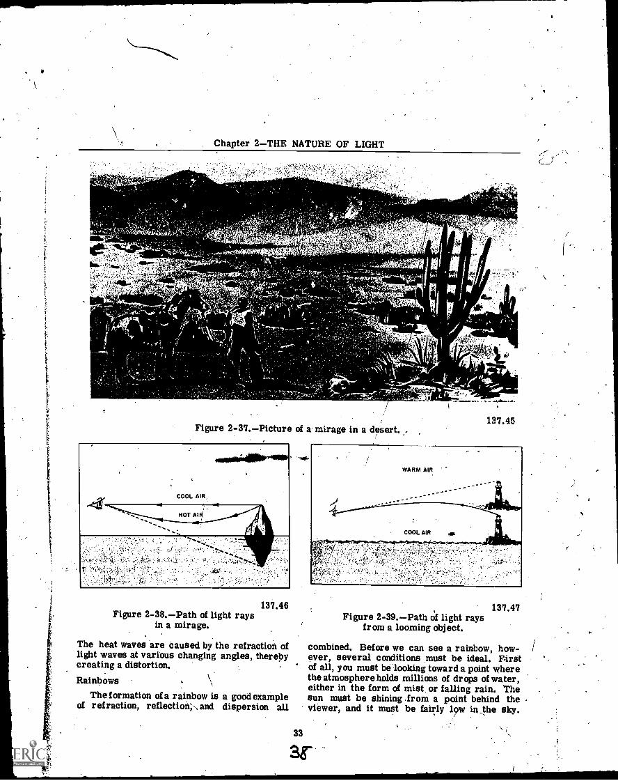
Chapter 2THE NATURE OF LIGHT
Figure 2-37.Picture of a mirage in a desert..
COOL AIR,
ssHOT
137.45
137.46Figure 2-38.Path of light rays
in a mirage.
The heat waves are caused by the refraction oflight waves at various changing angles, therebycreating a distortion.
Rainbows
The formation of a rainbow is a good exampleof refraction, reflection', and dispersion all
33
137.47Figure 2-39.Path of light rays
from a looming object.
combined. Before we can see a rainbow, how-ever, several conditions must be ideal. Firstof all, you must be looking toward a point wherethe atmosphere holds millions of drops of water,either in the form of mist or falling rain. Thesun must be shining .from a point behind theviewer, and it must be fairly low in the sky.
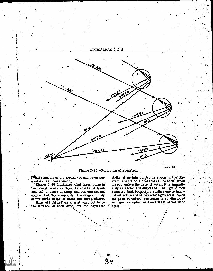
'.1
c.
*V'
OPTICALMAN 3 8: 2
Figure 2-40.Formation of a rainbow.
(When standing on the ground you can never seenatural rainbow at noon.)
figure 2-40 illustrates. what takes place inthe fo ation of a rainboiv. Of course, it takes.millions of..drops of water and you can see biXcolors, but,`for simplicity, the diagram, onlyshows three of water and three. colors.
Rays of light are = riking at many points onthe surface of each , but the rays that
137.48
strike at certain poiQts, as shown, in the dia-gram, are the only oneathat cant be seen. Whenthe ray enters the drop of water, it is immedi -,ately refracted and dispersed. The light is thenreflected back toward the surface due to inter-nal reflection and is refracted again as it leavesthe drop of water, continuing to be dispeisedinto spectral as it enters the atmosphere
e. again.
34
39
7
CHAPTER 3
MIRRORS AND PRISMS
The following chapter will be devoted prie-marilyto describing plane mirrors and prisms,and the effect they have on light transmission.However, before we get into the discussion ofmirrors and prisms, it is best to explain twoother basic knowledge factors. These aremeasurement systems used in optic imagedescriptions.'
MEASUREMENTS IN OPTICS
An Opticalman at various times works withat least four systems of measurement: theEnglish system, metric system, degree sys-tem, and the mil system. You are alreadyfamiliar -with the English system where thebasic unit of length is the foot. The basic unit,the foot, can be converted to smaller or largerunits by multiplying or dividing by known con-version factors. The English system is not en-tirely satisfactory for optical measurementsbecause it is complicated and cumbersome.The lack of simple relationships between unitsmakes it very difficult to' carry out computa-tioni. Hence, other systems of measurementare sometimes more desirable.
METRIC SYSTEM
Shortly- after the French Revolution, nearthe end of the 18th century, the National As-sembly of France decided to appoint a commis-sion for the purpose of developing a more logi-cal measuring system than those that werecurrent at that time: The product of that com-mission was the "metric system " which hasbeen adopted by most civilized countries exceptthe United States.
In 1960, the International Conference onWeights and- Meastires adopted a modernizedversion of the metric system called the Inter-
' national System of Units. Officially abbrevi-'at'ed SI, it was established by internationalagieement to provide a logical interconnectedframework for all measurements in -science,industry and commerce. The six base units _ofmeasure under-SI are:
35
Length = Meter - mMass = Kilogram - kTemperature = Kelvin - kTime = Second - sElectric Current = Ampere - ALuminous Intensity = Candela - cd
In your work as an opticalman; you will usethe metric system of measuring as well as theEnglish system. The diameter and focal lengthof lenses are usually- stated on optical drawings,for example, in millimetersnot in inches. Inaddition, with some experience, you will findthe metric system much easier to use than theEnglish system.
Decimals are basic in the metric system Ofmeasurement. You can easily convert fromone unit to another. Suppose you know that anobject, for example, is 0.67 meter long and youdesire the answer in decimeter. All you needdo is multiply by 10 and you get an answer of6.7 decimeters in length. If you wish the an-swer incentimeters, multiply by 100, and. youget 67 cm. For an answer in millimeters,multiply by 1,000 and you get'670 mm.
Suppose you desire to uselhe English sys-tem of measurement to get in feet an objectwhich is 0.67 yard long. You must multiplyby 3 to get the answer in feet, and by 36 to getthe answer in inches.
What, then, is the difference in using the-English or metric system of measurement?The English system has several conversionfactors, whereas, in the metric system, all youneed do is move the decimal point.
-The unit of length in the metric system isthe METER, which is eqiial to 39.37 inches. Ameter is divided into 100 equal parts calledcentimeters; and each centimeter is dividedinto ten parts called a millimeter, becauseeach millimeter is 1/1,000 part of a meter. Allunits of linear measurement of the metric sys-tem are multiples or fractional parts of a meterin units of 10.
Following is a table of metric unite;, withtheir equivalents in inches, yards; and miles:
OPTICALMAN 3 & 2
1,1 millimeter = .03937 inch
10 millimeters =1 centimeter = .393' inch10 centimeters = 1 decimeter = 3.937 inches10 decimeters = 1 meter = 1.0936 yards10 metera, = 1 dekameter = 10.936 yards10 dekameters = 1 hectometer = 109.36 yards10 hectometers = 1 kilometer .6214
Thenames of multiples in the metric sys-tem are formed by adding the Greek prefixes:DEKA (ten),HECTO (hundred), KILO (thousand),and MEGA (million). Sub-multiples of the sys-tem are formed by adding LATIN, PREFIXES:DECI (tenth), CENTI (hundredth), MILLI (thou-
MeterCenti -ger cmMilli eter mmLite . 1
Mill iter mlCubi centimeter ccGram_. 1g
-Kilogram kgMilligram mg"
DEGREE SYSTEM
_-_The degree system is a means of measuringand designating angles or arcs. A degree is1/36 of the circumference of a circle, or thevalue of the angle formed by dividing a .rightangle into 90 equal parts. Each degree is di-vided into 60-parts called minutes, and eachminute is divided into 60 parts called seconds.
sandth), and MICRO (millionth). _verston_fr___Oth.For -quick, approximatean m
inches to the metric system units, or viceversa, refer to a metric unit inch conversiontable, which your optical shop will have. Formore exact conversion and for conversion oflarge units, use the following table:
From To Multiply
Milli- .
meters .. Inches . . . met4s by . .03937Inches ..
meters. . Inches by . ,. 25.4Meters . .. Inches . . . Meters by, . . 39.37Meters . Yards . . Meters by. . . 1.0936Inches . .. Meters. . . Inches by . . . .0254Yards . .. Meters. . . Yards by . . . .9144Kilo- Kilo-
meters Miles meters by. . .6214.Miles. Kilo-
meters. . Miles by . . . 1.609
The unit of volume in the metric system isthe LITER,which is the volume of a cube 1/10tirof a meter on _each side. A liter is equal _to1,000 cubic centimeters which is equivalent to
1.-.0511quarts.,The unit of mass in the metric system is the
GRAM, the weight of one millimeter_ of distilledwater_ at 4°C. For all practical purposes, agram may be considered as the weight of onecubic centimeter (cc) of water.
The three standard units of the metric sys=tem (meter, liter, and gram) have decimalmultiples and sub-multiples which make it easyto use for all purposes. Every unit of length;volume, or mass is, exactly 1/10th the size ofthe next larger unit.
Standard abbreviations for principal metricunits are:
1,1tAVY .MIL
A Navy mil is a unit of measurement forankles, much smaller than a degree-1/6,400of the circumference of a circle.
A mil is the value of the acute angle oftriangle whose 'height is 1,000 time its base.For-example, when you look at an object 1,000meters distant and 1 meter wide, the object in-:
tercepts a visual angle of 1 mil. othei wayto say this is: A ma 1s .an ankle hose sine ortangent is 1/1,000. NOTE: Fr very smallangles, the sine and tangent are ractically, thesame. ..-
IMAGE DESCRIPTION
An image is' a representation or optical'counterpart of an object produced by means ellight raytan orining-:opticrirelinient
rmsfoiiiiiñageby, collecting a bundle of lightrays diverging from an object point and trans-'forming them into a bundle of rays which con-verge or diverge from another point. Ti thebeam. actually converges to a pOint, a REALIMAGE of the object is produced. If the beamdiverges from a point, it produces a VIRTUAL.IMAGE of the object.
REAL IMAGEA real image, is one that actually exists and
is produced when the rays of light coming froman object converge at a cofnmon point. The'image fOrmed by the lens of a camera on theground glass plate, as illustrated in figure 3-1,
36
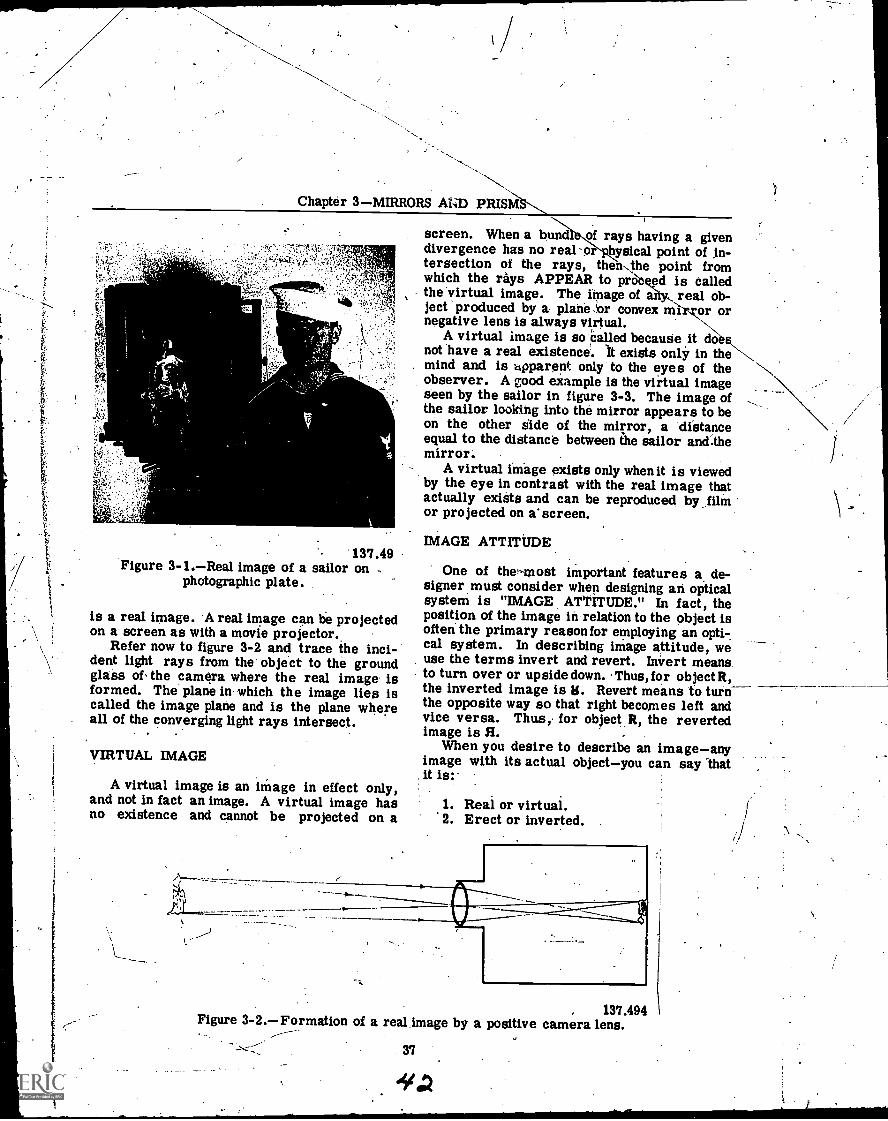
Chapter 3MIRRORS AND PRIS/s,
f
137.49Figure 3-1.Real image of a sailor on
photographic plate.
is a real image. A real image can be projectedon a screen as with a movie projector.
Refer now to figure 3-2 and trace the inci-dent light rays from the object to the groundglass of the camera where the real image isformed. The plane in which the image lies iscalled the image plane and is the plane whereall of the converging light rays intersect.
VIRTUAL IMAGE
A virtual image is an image in effect only,and not in fact an image. A virtual image hasno existence and cannot be projected on a
screen. When a bun of rays having a givendivergence has no real -o hysical point of in-tersection of the rays, thenthe point fromwhich the rays APPEAR to prat ed is calledthe virtual image. The image of real ob-ject produced by a plane ,or convex m or ornegative lens is always virtual.
A virtual image is so tailed becauseonly
doenot have a real existence. It exists only in themind and is .opparent only to the eyes of theobserver. A good example is the virtual imageseen by the sailor in figure 3-3. The image ofthe sailor looking into the mirror appears to beon the other side of the mirror, a distanceequal to the distance between the sailor and:themirror.
A virtual image exists only when it is viewedby the eye in contrast with the real image thatactually exists and can be reproduced by filmor projected on a'screen.
IMAGE ATTITUDE
One of the--most important features a de-signer must consider when designing an opticalsystem. is "IMAGE ATTITUDE." In fact, theposition of the image in relation to the object isoften the primary reason for employing an opti7cal system. In describing image attitude, weuse the terms invert and revert. Invert meansto turn over or upsidedown. Thus, for object R,the inverted image is R. Revert means to turnthe opposite way so that right becomes left andvice versa. Thus, for object R, the revertedimage is R. -
When you desire to describe an imageanyimage with its actual objectyou can say -thatit is:'
1. Real or virtual.2. Erect or inverted.
, 137.494Figure 3-2.Formation of a real image by a positive camera lens.
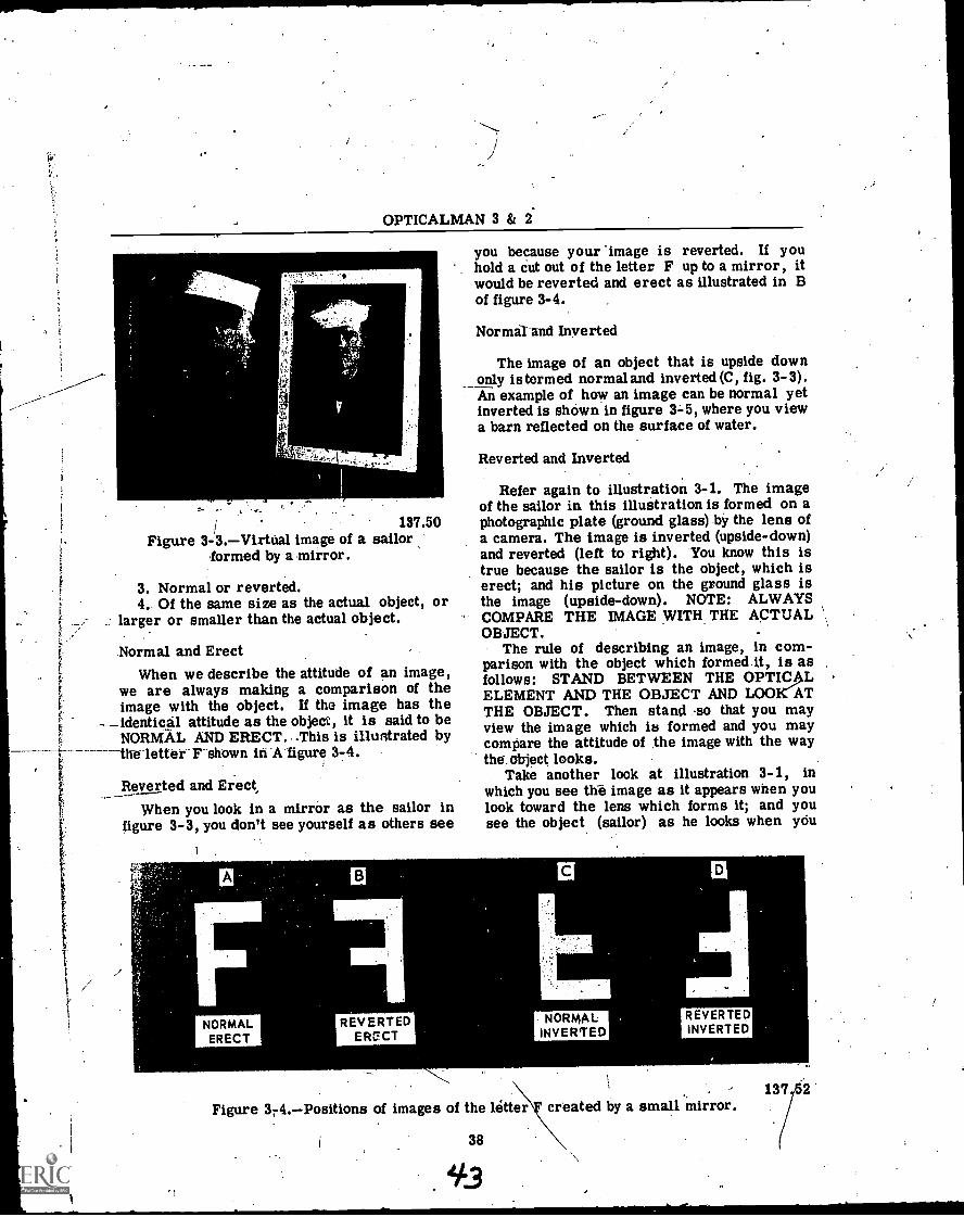
OPTICALMAN 3 & 2
I 137.50Figure 3-3.VirtUal image of a sailor
formed by a mirror.
3. Normal or reverted.4.. Of the same size as the actual object, or
larger or smaller than the actual object.
.Normal and Erect7 When we describe the attitude of an image,/f
we are always making a comparison of the1. image with the object. If the image has thet - identical attitude as the object, it is said to be
NORMAL AND ERECT.. -This is illustrated byWe letter F shown In-A 'figure 3-4.
t
Reverted and ErectWhen you look in a mirror as the sailor in
figure 3-3, you don't see yourself as others see
A
NORMALERECT
REVERTEDERUCT
you because your -image is reverted. If youhold a cut out of the letter F up to a mirror, itwould be reverted and erect as illustrated in Bof figure 3-4.
Normal-and Inverted
The image of an object that is upside downonly is termed normal and inverted (C, fig. 3-3).An example of how an image can be normal yetinverted is shown in figure 3-5, where you viewa barn reflected on the surface of water.
Reverted and Inverted
Refer again to illustration 3-1. The imageof the sailor in this illustration is formed on aphotographic plate (ground glass) by the lens ofa camera. The image is inverted (upside-down)and reverted (left to right). You know this istrue because the sailor is the object, which iserect; and his picture on the ground glass isthe image (upside-down). NOTE: ALWAYSCOMPARE THE IMAGE WITH THE ACTUALOBJECT. -
The rule of describing an image, in com-parison with the object which formed.lt, is asfollows: STAND BETWEEN THE OPTICALELEMENT AND THE OBJECT AND LOO ATTHE OBJECT. Then stand so that you mayview the image which is formed and you maycompare the attitude of the image with the waythe.object looks.
Take another look at illustration 3-1, inwhich you see the image as it appears when youlook toward the lens which forms it; and yousee the object (sailor) as he looks when you
Figure 3r4.Positions of images of the letter
1 38
3
C D
NORMALINVERTED
REVERTEDINVERTED
. 137created by a small mirror.
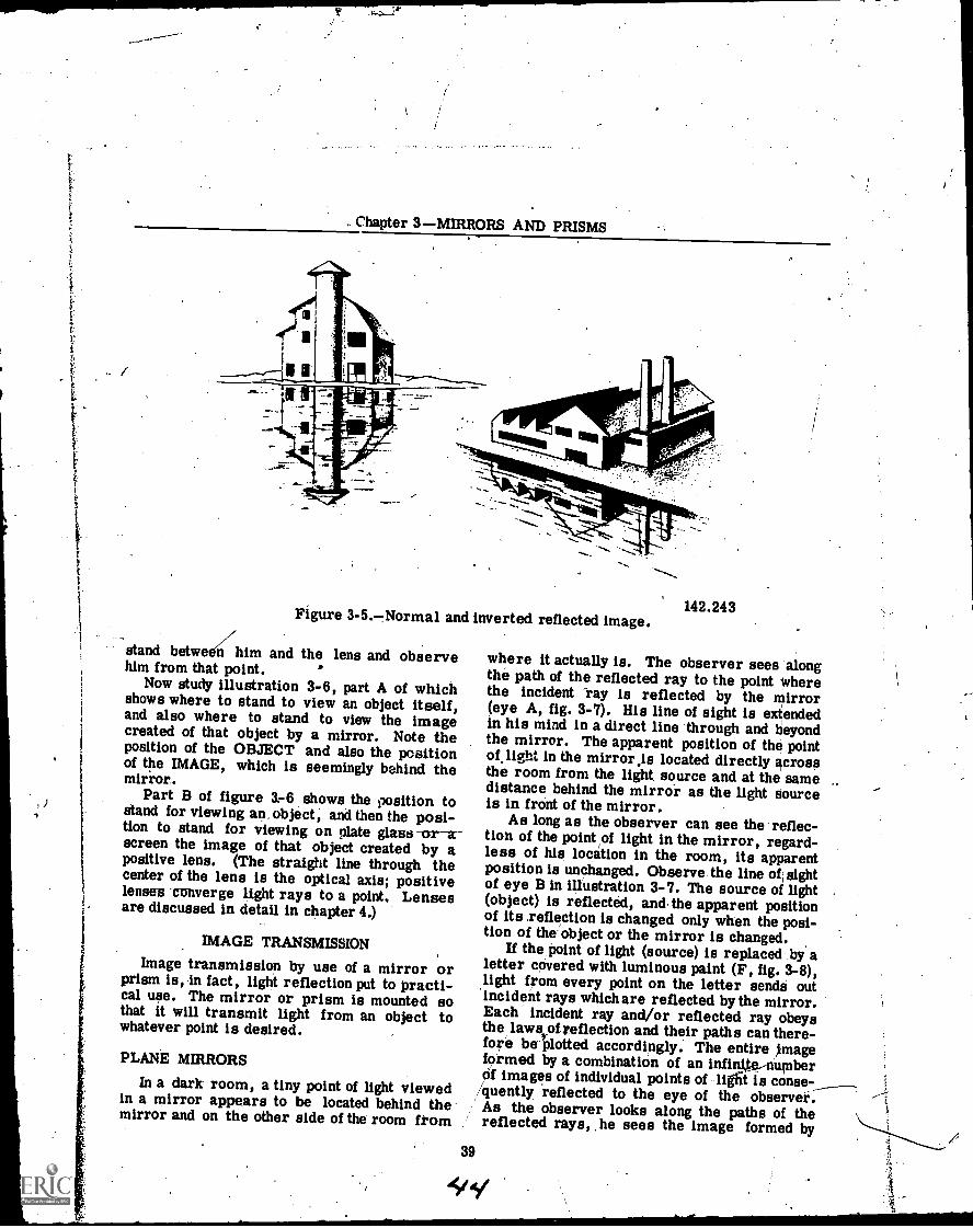
Chapter 3MIRRORS AND PRISMS
Figure 3-5.-,Normal and inverted reflected image.
stand betwe Iii/him and the lens and observehim from that point.
Now study illustration 3-6, part A of whichshows where to stand to view an object itself,and also where to stand to view the imagecreated of that object by a mirror. Note theposition of the OBJECT and also the positionof the IMAGE, which is seemingly behind themirror.
Part B of figure 3.-6 shows the position tostand for viewing an, object, and then the posi-tion to stand for viewing on plate glass -or-ascreen the image of that object created by apositive lens. (The straight line through thecenter of the lens is the optical axis; positivelenses-converge light rays to a point. Lensesare discussed in detail in chapter 4.)
IMAGE TRANSMISSION
Image transmission by use of a mirror orprism is, in fact, light reflection put to practi-cal use. The mirror or prism is mounted sothat it will transmit light from an object towhatever point is desired.
PLANE MIRRORS
In a dark room, a tiny point of light viewedin a mirror appears to be located behind themirror and on the other side of the room fkom
142.243
where it actually is. The observer sees alongthe path of the reflected ray to the point wherethe incident "ray is reflected by the Mirror(eye A, fig. 3-7). His line of sight is extendedin his mind in a direct line through and beyondthe mirror. The apparent position of the pointof.light in the mirror.is located directly crossthe room from the light, source and at the samedistance behind the mirror as the light Sourceis in front of the mirror.
As long as the observer can see the reflec-tion of the point of light in the mirror, regard-less of his location in the room, its apparentposition is unchanged. Observe the line ofi sightof eye B in illustration 3-7. The source of light(object) is reflected, and the apparent positionof its .reflection is changed only when the posi-tion of the object or the mirror is changed.
If the point of light (source) is replaced by aletter covered with luminous paint (F, fig. 3-8),light from every point on the letter sends outincident rays which are reflected by the mirror.Each incident ray and/or reflected ray obeysthe laws of reflection and their paths can there-fore be plotted accordingly. The entire imageformed by a combination of an infinite.-numberOf images of individual points of light is
/quently reflected to the eye of the observei.As the observer looks along the paths of thereflected rays, he sees the image formed by
39
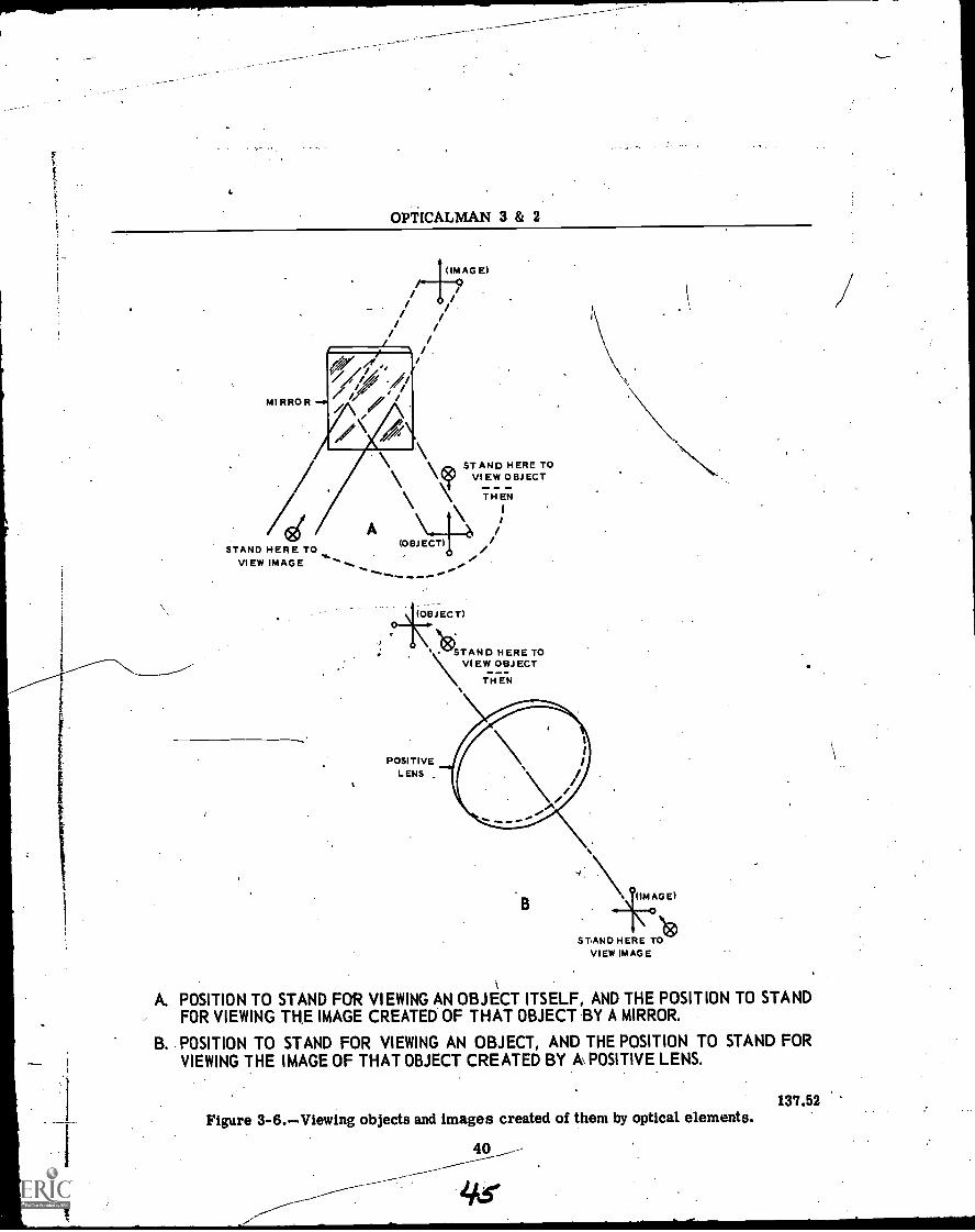
Y.
OPTICALMAN 3 & 2
MIRROR -
(IMAGE)AG El
0/ /
/ //
;//,/,
\lz)ST AND HERE TOVIEW OBJECT
THEN
A \STAND HERE TO (OBJECT)
VIEW IMAGE
(OBJECT)
`STAND. STAND HERE TO\ VIEW OBJECT
THEN
POSITIVEL ENS
B\ 0(IM AGE)
STAND H ERE TOItit)
VIEW IMAGE
A. POSITION TO STAND FOR VIEWING AN OBJECT ITSELF, AND THE POSITION TO STANDFOR VIEWING THE IMAGE CREATED OF THAT OBJECT BY A MIRROR.
B. POSITION TO STAND FOR VIEWING AN OBJECT, AND THE POSITION TO STAND FORVIEWING THE IMAGE OF THAT OBJECT CREATED BY A\ POSITIVE LENS.
Figure 3-6.Viewing objects and images created of them by optical elements.137.52
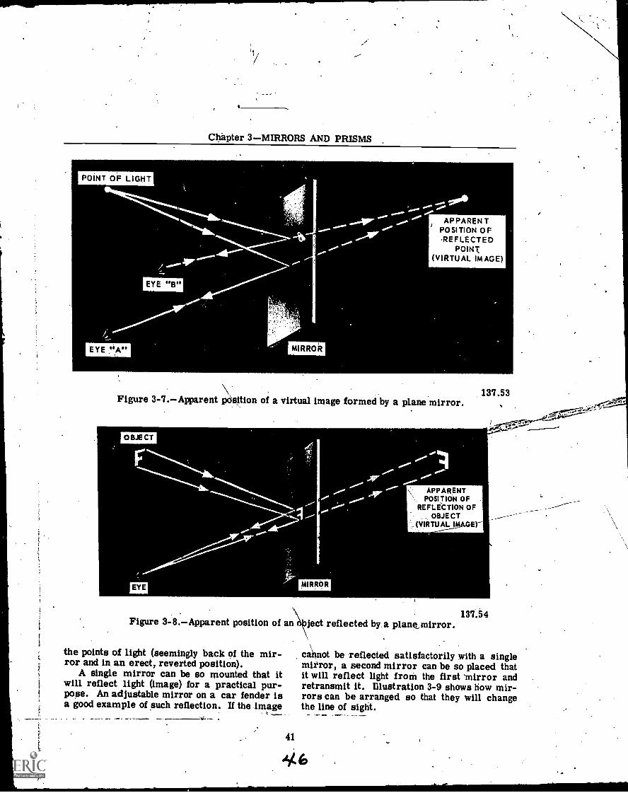
Chapter 3MIRRORS AND PRISMS ,
POINT OF LIGHT
EYE "B"
EYE "A"
tia
MIRROR
AP PAREN TPOSITION OFREFLECTED
POINT(VIRTUAL IMAGE)
Figure 3-7.Apparent position of a virtual image formed by a plane mirror.
OBJECT
EYE
Figure 3-8.Apparent position of an
the points of light (seemingly back of the mir-ror and in an erect, reverted position).
A single mirror can be so mounted that itwill reflect light (image) for a practical pur-pose. An adjustable mirror on a car fender isa good example of such reflection. If the image
MIRROR
137.53
APPARENTPOSITION OF
REFLECTION OFOBJECT
, (VIRTU AL IMAGO"-
137.54ject reflected by.a planQmirror.
cannot be reflected satisfactorily with a singlemirror, a second mirror can be so placed thatit will reflect light froM the first 'mirror andretransmit it. Illustration 3-9 shows how mir-rors can be arranged so that they will changethe line of sight.
41
4b
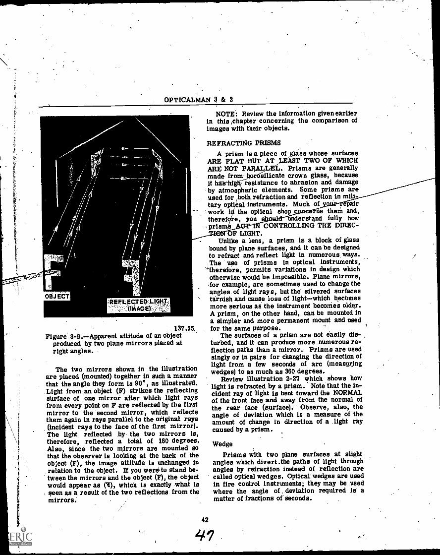
GPTICALMAN 3 & 2
4
OBJECTREFLECTED.LIGHT.;
(IMAGE),,,
137.55.Figure 3-9.Apparent attitude of an object
produced by two plane mirrors placed atright angles.
The two mirrors shown in the illustrationare placed (mounted) together in such a mannerthat the angle they form is 90°, as illustrated.Light from an object (F) strikes the reflectingsurface of one mirror after which light raysfrom every point on F are reflected by the firstmirror to the second mirror, which reflectsthem again in rays parallel to the original rays(incident rays to the face of the first mirror).The light reflected by the two mirrors is,therefore, reflected a total of 180 degrees.Also, since the two mirrors are mounted sothat the observer is looking at the back of theobject (F), the image attitude Is unchanged inrelation to the object. If you were to stand be-tween the mirrors and the object (F), the objectwould appear as (I), which is exactly what isseen as a result of the two reflections from themirrors.
NOTE: Review the information given earlierin this ,chapter concerning the comparison ofimages with their objects.
REFRACTING PRISMS
A prism is a piece of _glass whose surfacesARE FLAT BUT.112.,EAST TWO OF WHICHARE NOT PARAL . Prisms are generallymade from bor silicate crown glass, becauseit hieldghiesistance to abrasion and damageby atmospheric elements. Some prisms areused for /both refraction and reflection in mili-tary opt cal instruments. Much of pairwork i the optical shop ns theM and,theref e you understand fully howpris CONTROLLING THE DIREC-
OF LIGHT.Unlike a lens, a prism is a block of glass
bound by plane surfaces, and it can be designedto refract and reflect light in numerous ways.The use of prisms in optical instruments,
'therefore, permits variations in design whichotherwise would be impossible. Plane mirrors,for example, are sometimes used to change theangles of light rays, but the silvered surfacestarnish and cause loss of lightwhich becbmesmore serious as the instrument beconies older.A prism, on the other hand, can be mounted ina simpler and more permanent mount and usedfor the same purpose.
The surfaces of a prism are not easily dis-turbed, and it can produce more numerous re-flection paths than a mirror. Prisms are usedsingly or in pairs for changing the direction oflight from a few seconds of arc (measuringwedges) to as much as 360 degrees.
Review illustration 2-27 which shows howlight.is refracted by a prism. Note that the in-cident ray of light is bent toward the NORMALof the front face and away from the normal ofthe rear face (surface). Observe, also, theangle of deviation which is a measure of theamount of change in direction of a light raycaused by a prism.
Wedge
Prisms with two plane surfaces at slightangles which divert the paths of light throughangles by refraction instead of reflection arecalled optical wedges. Optical' wedges are usedin fire control instruments; they may be usedwhere the angle of deviation required is amatter of fractions of seconds.
42
41
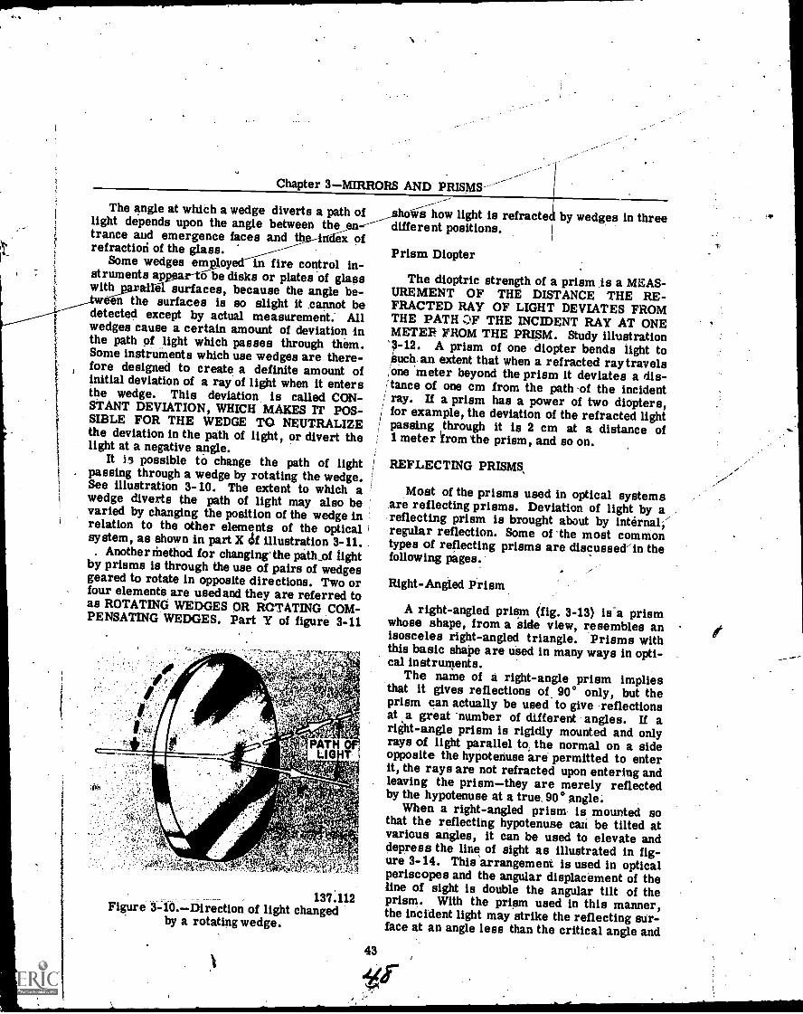
Chapter 3MIRRORS AND PRISMS'
The angle at which a wedge diverts a pathlight depends upon the angle between the entrance and emergence faces and the-hid6X ofrefracticni of the glass.
Some wedges employe in fire control in-struments ap r-tfibe disks or plates of glasswith surfaces, because the angle be-
en the surfaces is so slight it cannot bedetected except by actual measurement: Allwedges cause a certain amount of deviation inthe path of light which passes through them.Some instruments which use wedges are there-fore designed to create a definite amount ofinitial deviation of a ray of light when it entersthe wedge. This deviation, is called CON-STANT DEVIATION, WHICH MAKES IT POS-SIBLE FOR THE WEDGE TO NEUTRALIZEthe deviation in the path of light, or divert thelight at a negative angle.
It is possible to change the path of lightpassing through a wedge by rotating the wedge.See illustration 3-10. The extent to which awedge diverts the path of light may also bevaried by changing the position of the wedge inrelation to the other elements of the opticalsystem, as shown in part X rgif illustration 3-11.
. Another Method for changing'the path_of lightby prisms is through the use of pairs of wedgesgeared to rotate in opposite directions. Two orfour elements are used and they are referred toas ROTATING WEDGES OR ROTATING COM-PENSATING WEDGES. Part Y of figure 3-11
137.112Figure 3-10.Direction of light changed
by a rotating wedge.
hoSis how light is refracted by wedges in threedifferent positions.
Prism Diopter
The dioptric strength of a prism is a MEAS-UREMENT OF THE DISTANCE THE RE-FRACTED RAY OF LIGHT DEVIATES FROMTHE PATH OF THE INCIDENT RAY AT ONEMETER FROM THE PRISM. Study illustration'3-12. A prism of one diopter bends light tosuch an extent that when a refracted ray travels,one meter beyond the prism it deviates a dis-itance of one cm from the path of the incidentray. If a prism has a power of two diopters,for example, the deviation of the refracted lightpassing through it is 2 cm at a distance of1 meter from the prism, and so on.
REFLECTING PRISMS,
Most of the prisms used in optical systemsare reflecting prisms. Deviation of light by areflecting prism is brought about by internal;regular reflection. Some of the most commontypes of reflecting prisms are discussed/in thefollowing pages.
Right-Angled Prism
A right-angled prism (fig. 3-13) is-a prismwhose shape, from a side view, resembles anisosceles right-angled triangle. Prisms withthis basic shape are used in many ways in opti-cal instruments.
The name of a right-angle prism impliesthat it gives reflections of, 90° only, but theprism can actually be used to give reflectionsat a great number of different angles. If aright-angle prism is rigidly mounted and onlyrays of light parallel to, the normal on a sideopposite the hypotenuse are permitted to enterit, the rays are not refracted upon entering andleaving the prismthey are merely reflectedby the hypotenuse at a true. 90° angle.
When a right-angled prism is mounted sothat the reflecting hypotenuse can be tilted atvarious angles, it can be used to elevate anddepress the line of sight as illustrated in fig-ure 3-14. This arrangement is used in opticalperiscopes and the angular displacement of theline of sight is double the angular tilt of theprism. With the prism used in this manner,the incident light may strike the reflecting sur-face at an angle less than the critical angle and
43
!,f
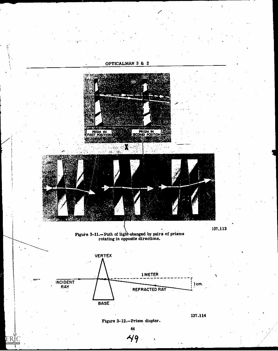
OPTICALMAN 3 & 2
Figure 3-11.Path of ligh ed by pairs of prismsrotating in opposite directions.
INCIDENTRAY
VERTEX
1 METER
BASE
REFRACTED RAY .
Figure 3-12.Prism diopter.
44
1cm.
137.114
137.113
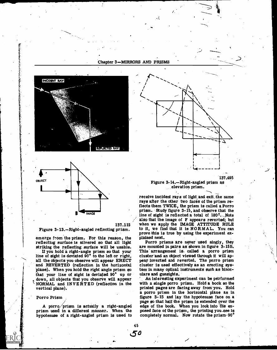
Chapter 3MIRRORS AND PRISMS
INCIDENT RAY
137.115Figure 3- 13.Right-angled reflecting prism.
emerge from the prism. For this reason, thereflecting surface is silvered so that all lightstriking the reflecting .surface will be usable.
If you hold a right-angle prism so that yourline of sight is deviated 90° to the left or right,all the objects you observe will appear ERECTand REVERTED (reflection in the horizontal'plane). When you hold the right angle prism sothat your line of sight is deviated 90° up ordown, all objects that you observe will appearNORMAL and INVERTED (reflection in thevertical plane).
Porro Prism
A porro prism is actually a right-angledprism used in a different manner. When thehypotenuse of a right-angled prism is used to
I lb
/
137.495Figure 3-14.Right-angled prism as
elevation prism.
receive incident rays of light, and exit, lie samerays after the other two faces of the prism re-flects them TWICE, the prism is called a Porroprism. Study figure 3-15, and observe that theline of sight is reflected a total of 180.-,Notealso that the image of F appears reverted; butwhen we apply the IMAGE ATTITUDE RULEto it, we find that it is NORMAL. You canprove this is true by using the experiment ex-plained next.
Porro prisms are never used singly, theyare mounted in pairs as shown in figure 3-15B.This arrangement is. called a porro prismcluster'and an object viewed through it will ap-pear inverted and reverted. The porro prismcluster is used effectively as an erecting sys-tem- in many optical instruments such as binoc-ulars and gunsights.' An interesting experiment can be pe'rformedwith a single porro prism. Hold a book so theprinted pages are facing away from.you. Holda porro prism in the horizontal plane as infigure 3-15 and lay the hypotenuse face on apage so that half the prism is extended over theedge of the book. When you look into Ilie ex-posed face of the prism, the printing you-see iscompletely normal. Now rotate the prism-90°
45
CTa
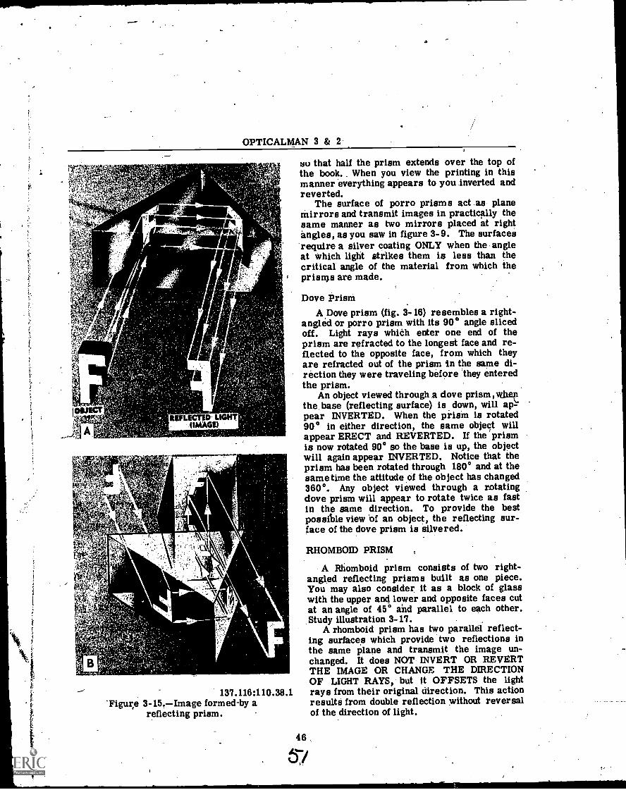
OPTICALMAN 3 & 2
4 E.
'XP.71
V4.474AV:1 I
lama7,1 A
,61.111/w,
4.
a
REFLECTED LIGHT(IMAGE)
'Figur,e137.116:110.38.1
3-15.Image formed by areflecting prism.
4
so that half the prism extends over the top ofthe book.. When you view the printing in thismanner everything appears to you inverted andreverted.
The surface of porro prisms act .as planemirrors and transmit images in practically thesame manner as two mirrors placed at rightangles, as you saw in figure 3-9. The surfacesrequire a silver coating ONLY when the angleat which light strikes them is less than thecritical angle of the material from which theprisms are made.
Dove PrismA Dove prism (fig. 3-16) resembles a right-
angled or porro prism with its 90° angle slicedoff. Light rays which enter one end of theprism are refracted to the longest face and re-flected to the opposite face, from which theyare refracted out of the prism in the same di-rection they were traveling before they enteredthe prism.
An object viewed through .a dove prism,w.henthe, base (reflecting surface) is down, will ap-pear INVERTED. When the piism is rotated90° in either direction, the same object willappear ERECT and REVERTED. If the prismis now rotated 90° so the base is up, the objectwill again appear INVERTED. Notice that theprism has been rotated through 180° and at thesame time the attitude of the object has changed360°. Any object viewed through a rotatingdove prism will appear to rotate twice as fastin the same direction. To provide the bestpossible view 'of an object, the reflecting sur-face of the dove prism is silvered.
RHOMBOID PRISM
A Rhomboid prism consists of two right -angled reflecting prisms built as one piece.You may also consider it as a block of glasswith the upper and lower and opposite faces cutat an angle of 45° and parallel to each other.Study illustration 3-17.
A rhomboid prism has two parallel reflect-ing surfaces which provide two reflections inthe same plane and transmit the image un-changed. It does NOT INVERT OR REVERTTHE IMAGE OR CHANGE THE DIRECTIONOF LIGHT RAYS, but It OFFSETS the lightrays from their original direction. This actionresults from double reflection without reversalof the direction of light.
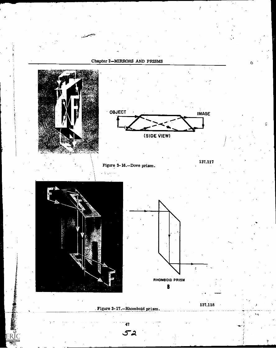
Chapter 3MIRRORS AND PRISMS
Mt
t"
(SIDE VIEW)
Figure 3- 16.Dove prism.137.117
RHOMBOID PRISM
B
Figure 3- 17.Rhomboid prism.
47
.. 0
137.118
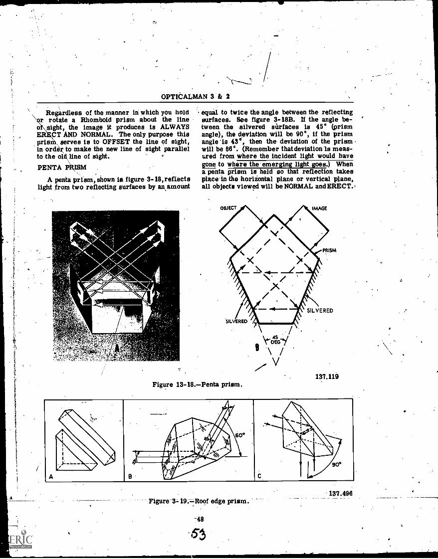
N
OPTICALMAN 3 & 2
Regardless of the manner in which you holdr rotate a Rhomboid prism about the line
o sight, the image it produces is ALWAYSCT AND NORMAL. The only purpose this
prism\ serves is to OFFSET the line of sight,in order to make the new line of sight parallelto the okkline of sight.
PENTA PRISM
A penta prism, shown iei figure 3-18, reflectslight from two reflecting surfaces by an amount
IMERM11111M1
zz
40.1
k
Ar=i-
equal to twice the angle between the reflectingsurfaces. See figure 3-18B. If the angle be-tween the silvered surfaces is 45° (prismangle), the deviation will be 90°, if the prismangle 'is 43°, then the deviation of the prismwill be 86°. (Remember thatdeviationis meas-ured from where the incident light would havegone to where the emerging light goes.) Whena penta prism is held so that reflection takesplace in the horiiontal plane or vertical plane,all objects viewed will be NORMAL and ERECT.
Figure 13-18.Penta prism.137.119
Figure 3- 19. Roof edge prism.
-48
137.496
0
4

r0
Chapter 3MIRRORS AND PRISMS
The prism may even be rotated' Slightly withoutchanging the apparent position of the objectviewed. This is called Constant Deviation. Theconstant deviation feature of the penta prism isvery useful in rangefinders which rely on opti -.cal wedges to measure the deviation of the lineof sight.
Roof Edge Prism
The construction of the roof edge prism willbe easy to miderstand by referring to Part A offigure 3-19. Basically the roof edge prism be-haves as if it were composed of two right-angleprisms, as shown in Part A and Part C of fig-ure 3-19. Light enters perpendicular, to one
5
surface, reflects left to right and right to leftfrom the roof edge, and is also reflected toemerge perpendicular to the second surface.Light reflected from the roof edge in thismanner will cause objects to appear INVERTEDand REVERTED..
The roof edge prism may be ground so thatdeviation of the line of sight is 90° (Part C,fig. 3-19) or 60° (Part B, fig. 3-19). Whateverthe deviation of the prism; light will alwaysenter and leave the prism perpendicular to theentrance and emergence faces.
The reflecting surfaces are not silvered, butthe rbof edge of the 'reflecting Nrface must beprotected against chipping. Any chips to thisedge will show up in the line of sight.
49
11
Ns '4
f,
CHAPTER 4
LENSES-
The basis for the construction of all opticalinstruments is to control the light travelingfrom an object, so that we may view the objectmore effectively with the instrument than wecan with our naked eye. Of all the various opti-cal elements used to control light, LENSES arethe most important and most widely used. Likethe prisms and mirrors that 'you studied in theprevious chapter, lenses are made from highquality optical glass.
Ordinary and optical- glass differ greatly intheir chemical composition, and also in themanufacturing process. The only commoncharacteristic of all glass is that it is AMOR-PHOUS. This means that glass does not havea definite or crystalline structure as solidbodies do..
The properties of glass are explainable onlyby assuming that they have the same moleculararrangement as a LIQUID. When. a crystallinebody passes from the/liquid to the solid state,the transition takes place at a definite tempera-ture and is accompanied by considerable heatwhich temporarily halts solidification. Withglass, on the other hand, -the transition fromthe liquid to the solid state is so continuous andgradual that the most delicate instruments havefailed to record either evolution of heat or re-tardation of the solidifying process, which is aGRADUAL STIFFENING WITHOUT CHANGE'OF STRUCTURE. All glass, however, assumesa crystalline structure (devitrification) if whilein the -vitreous state the temperature is main-tained too long at the critical state (crystalliza-tion point). Crystalline glass gives DOUBIIErefraction, and a lens made from it forms TWOSEPARATE IMAGES at the same time. .
. Glass has NO melting point. When heat isapplied to it gradually, it gets soft and can bemolded into a thread; when it is red hot, itflows in a thick mass. A temperature of several'thousand degrees turns 'glass into a fluid.
In a liquid state, glass is a MIXTURE of cer-tain chemicals in solution. The most commonchemicals used for this purpose are the silicates'and borates. Under ordinary conditions of
cooling, these chemical solutions remain mutu-ally dissolved.
Although- glass is a liquid, it is also a solid,which scientists generally describe as AMOR-PHOUS. Solids 'tare characterized by definiteshape and volume. Crystalline solids, for ex-ample, have a regular arrangement of particles;amorphous solids, on the other hind, have arandom arrangement of particleslarge, long-chain, entangled molecules.
You perhaps wonder how anything as SOLIDas glass can be a LIQUID or in an AMORPHOUSstate. The reason for this condition of glass isthat the molecules are held together in crystalsby VAN DER WAALS FORCES, which meansthat the electric field of the atoms of one mole-cule causes a similar variation in the electricfield of the atoms of another molecule to gen-erate attraction between them.
You can prove for yourself that GLASS IS AN .AMORPHOUS STATE by placing a thin-walledglass tube live feet long (approximately) Oh twonails -driven equidistant from the deck on thebulkhead of your shop and observing the hend inthe tube during a five or six/ months' period.Hold the glass tube against the bulkhead andmark its original position with a pencil., so thatyou will be able to measure the amount of bendwhich develops. during the period..
One interesting thing' about this test is thatwhen you first place the tube of glass on thenails it shows a slight bend, which immediatelydisappears if you then remove it froth the nails.At the end of your test, however, the bendwili--)remain in the tube when you remove it from thenails; because the liquid glass has ACTUALLY----'FLOWED tb its new positioi.
The PURELY OPTICAL PROPERTIES whichdirectly influence light as W passes throughglass include: -(1) homogeneity, (2) transpar-ency, (3) freedom from color, (4) refraction,and (5) dispersion.
Homogeneity is the most important propertyof' optical glass. If you examine a thick pieceof ordinary glass, you' will find that the layersof difference densities show clearly in the form
111
50
55
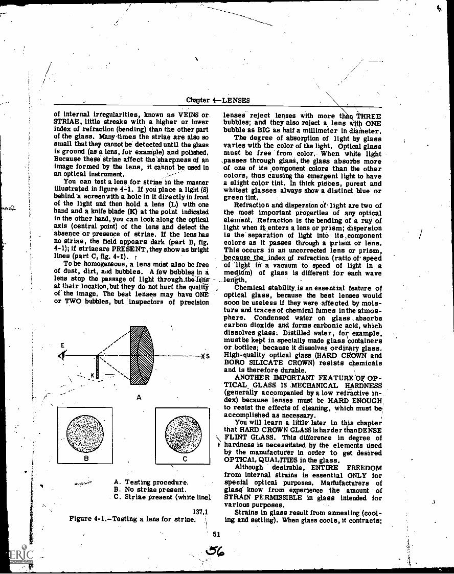
Chapter 4LENSES
of internal irregularities, known as VEINS or.STRIAE, little streaks with a higher or lowerindex of refraction (bending) than the other partof the glass. Manytimes the striae are also sosmall that they cannot be detected until the glassis ground (as a lens, for example) and polished.Because these striae affect the\sharpness of animage formed by the lens, it cannot be used inan optical instrument.
You can test a lens for striae in the mannerillustrated in figure 4-1. If you place a light (S)behind_' screen with a hole in it directly in frontof the light and then hold a lens (L) with onehand and a knife blade (K) at the point indicatedin the other hand, you can look along the opticalaxis (central point) of the lens and detect theabsence or presence of striae. If the lens hasno striae, the field appears dark (part B, fig.4-1); if striae are PRESENT, they showas brightlines (part C, fig. 4-1). r
To be homogeneous, a lens must also be freeof dust, dirt, add bubbles. A few bubbles in alens stop the passage of light through.the-ke-at their location, but they do not hurt the qualityof the image. The best lenses may have ONEor TWO bubbles, but inspectors of precision
A
A. Testing procedure.B. No striae present.C. Striae present (white line).
1374Figure 4-1.Testing a lens for striae.
lenses reject lenses with more t THREEbubbles; and they also reject a lens w pi ONEbubble as BIG as half a millimeter in dianieter.
The degree of absorption of light by glassvaries with the color of the light. Optical glassmust be free from color. When white light_passes through glue, the glass absorbs moreof one of its component colors than the othercolors, thus causing the emergent light to havea slight color tint. In thick pietes, purest andwhitest glasses always show a distinct blue orgreen tint.
Refraction and dispersion oflight are two ofthe most important properties of any opticalelement. Refraction is the bending of a ray oflight when it.enters a lens or prism; dispersionis the separation of light into its ,componentcolors as it passes through a prism orThis occurs in an uncorrected lens or prism,because the index of refraction (ratio of speedof -lig t in a vacuum to speed of light in amed m) of glass is different for each wavele gth.
Chemical stability. is an essential feature ofoptical glass, because the best lenses wouldsoon be useless if they were affected by mois-ture and traces of chemical fumes in the atmos-phere. Condensed water on glass . absorbscarbon dioxide and forms carbonic acid, whichdissolves glass. Distilled water, example,must be kept in specially made glass containersor bottles; because it dissolves ordinary glass.High-quality optical glass (HARD CROWN andBORO SILICATE CROWN) resists chemicalsand is therefore durable.
ANOTHER IMPORTANT FEATURE OF OP-TICAL GLASS IS ,MECHANICAL HARDNESS(generally accompanied by a low refactive in-dex) because lenses must be HARD ENOUGH,to resist the effects of cleaning, which must beaccomplished as necessary.
You will learn a little' later in th%s chapterthat HARD CROWN GLASS is harder than DENSEFLINT GLASS. This difference in degree ofhardness is necessitated by the elements usedby the manufacturer in order to get desiredOPTICAL.QUALITIES in the glass.
Although desirable, ENTIRE FREEDOMfrom internal strains is essential ONLY forspecial optical purposes. Maifufacturers ofglass' know from experience the amount ofSTRAIN PERMISSIBLE in glass intended forvarious purposes.
Strains in glass result from annealing (cool-ing and setting). When glass cools, it contracts;
t
51
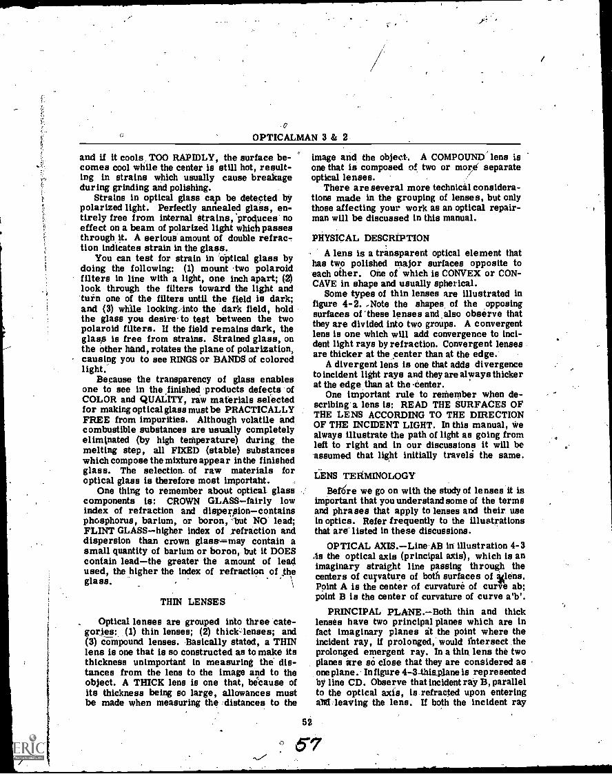
.0OPTICALMAN 3 & 2
and if it cools. TOO RAPIDLY, the surface be-comes cool while the center is still hot, result-ing in strains which usually cause breakageduring grinding and polishing.
Strains in optical glass cap be detected bypolarized light. Perfectly annealed glass, en-tirely free from internal Strains, 'produces noeffect on a beam of polarized light which passesthrough it. A serious amount of double refrac-tion indicates strain in the glass.
You can test for strain in optical glass bydoing the following: (1) mount two polaroidfilters in line with a light, one inch apart; (2)look through the filters toward the light andturn one of the filters until the field is dark;and (3) while looking into the dark field, holdthe glass you desire to test between the twopolaroid filters. If the field remains dark, theglass is free from strains. Strained glass, onthe other hand, rotates the plane of polarization,causing you to see RINGS or BANDS of coloredlight.
Because the transparency of glass enablesone to see in the finished products defects ofCOLOR and QUALITY, raw materials selectedfor making optical glass must be PRACTICALLYFREE from impurities. Although volatile and,combustible substances are usually completelyeliminated (by high temperature) during, themelting step, all FIXED (stable) substanceswhich compose the mixture appear in the finishedglass. The selection- of raw materials foroptical glass is therefore most importaht.
One thing to remember about optical glasscomponents is: CROWN GLASSfairly lowindex of refraction and dispersioncontainsphosphorus, barium, or boron, 'but NO lead;FLINT GLASShigher index of ,refraction anddispersion than crown glast ---may contain asmall quantity of barium or boron, but it DOEScontain leadthe greater the amount of leadused, the higher the index of refraction of theglass.
THIN LENSES
_ Optical lenses are grouped into three cate-gories :- (1) thin lenses; (2) thick-lenses; and(3) compound lenses. Basically stated, a THINlens is one that is so constructed as to make itsthickness unimportant in measuring the dis-tances from the lens to the image and to theobject. A THICK lens is one that, because ofits thickness being so large, allowances mustbe made when measuring the distances to the
image and the object. A COMPOUND lens isone that is composed of two or more separateoptical lenses.
There are several more technical considera-tions made in the grouping of lenses, but onlythose affecting your work as an optical repair-man will be discussed in this manual.
52
PHYSICAL DESCRIPTION
A lens is a transparent optical element thathas two polished major surfaces opposite toeach other. One of which is CONVEX or CON-CAVE in shape and usually spherical.
Some types of thin lenses are illustrated infigure 4-2. -Note the shapes, of the opposingsurfaces of 'these lenses and also observe thatthey are divided into two groups. A convergentlens is one which will add convergence to inci-dent light rays by refraction. Convergent lensesare thicker at the center than at the edge.
A divergent lens is one that adds divergenceto incident light rays and they are always thickerat the edge than at the center.
One important rule to remember when de-scribing a lens is: READ THE SURFACES OFTHE LENS ACCORDING TO THE DIRECTIONOF THE INCIDENT LIGHT. In this manual, wealways illustrate the path of light as going fromleft to right and in our discussions it will beassumed that light initially traveli the same.
LENS TERMINOLOGY
Befiire we go on with the study of lenses it isimportant that you understand some of the termsand phrases that apply to lenses and their usein optics. Refer frequently to the illustrationsthat are' listed in these discussions.
OPTICAL AXIS.Line AB in illustration 4-3As the optical axis (principal axis), which is animaginary straight line passing through thecenters of curvature of both surfaces of %lens.Point A is the center of curvature of curve ab;point B is the center of curvature of curve a'b'.
PRINCIPAL PLANE.Both thin and thicklenses have two principal planes which are infact imaginary planes at the point where theincident ray, if prolonged,' would intersect theprolonged emergent ray. In a thin lens the twoPlanes are so close that they are considered asone plane. In figure 4-3-thiaplane is rep resentedby line CD. Observe that incident ray B, parallelto the optical axis, is refracted upon enteringa1[8: leaving the lens. If both the incident ray

Chapter 4-LENSES
DOUBLE CONVEX PLANO-CONVEX
CONVERGING LENSES
CONVEXO-CONCAVEMENISCUS CONVERGING
IBLE CONCAVE. PLANO-CONCAVE
DIVERGING 'LENSES
Figure 4-2.-Types of thin lenses.
and the emergent ray are extended,as indicatedby the dotted lines, they would intersect at "d"on the principa3 ,plane.
OPTICAL CENTER.-The point in a lensthrough which light rays pass without deviationis the optical center. In thin lenses the opticalcenter is located on the optical axis, HALFWAYBETWEEN.THE TWO CURVED SURFACES OFTHE LENS. This is indicated by the letter 0in figure 4-3 and in a thin lens the optical cen-ter will be intersected by the principal plane.
PRINCIPAL FOCAL POINT (Principal Fo-cus).-The principal focus is the point whereparallel incident rays converge after they-paisthrough a convergent lens. Ev onvergentlens has two points of p pal focus, one oneach side. The point of principal focus on theleft side of the lens is the PRIMARY FOCALPOINT, (F-1-fig. 4-3); the point of principalfocus on the right of the lens is the SECOND-ARY FOCAL POINT (F2). The incident ray (B)is parallel to the optical axis and, after it Is
53
CONCAVO-CONVEXMENISCUS DIVERGING
137.69
refracted by the lens; passes through the SEC-ONDARY focal point (F2). Ray (C) passesthrough the optical axis at the primary focalpoint (F1), and is refracted by the lens and be-comes parallel to the axis.
This may seem confusing but if you referback to Chapter 2 where you studied the LAWOF REVERSIBILITY the fact that a lens canhave two principal focal points is understandable.
. PRINCIPAL FOCAL PLANE.-The principalfocal plane is an imaginary line (HI and H'I')perpendicular to the optical axis' at the pointsof principal focus. (Fig. 4-3.)
PRINCIPAL IMAGE PLANE.-The principalimage plane is an imaginary line (LM, fig. 4-3)Perpendicular to the optical axis at the pointwhere the image is formed. The principal imageplane may be located anywhere along the opticalaxis of the lens-from its focal point to infinity.Curvature
The amount of departure from a flat surface,as applied to lenses, is termed curvature.
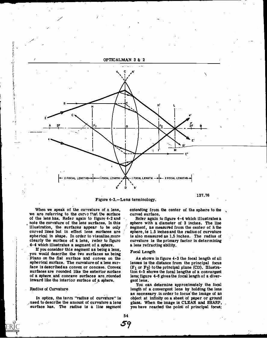
I
OPTICALMAN 3 & 2
B
C
I
H' L
A 2F 2F B
[0 2 FOCAL LENGTH+ (FOCAL LENGTH
D
I FOCAL LENGTH 2 FOCAL LENGTHS{
b'
Figure 4-3.Lens terminology.
When we speak of the curvature of a lens,we are referring to the curve that. the surfaceof the lens has. Refer again to figure 4-2 andnote the curvature of the lens surfaces. In thisillustration, the surfaces. appear to be onlycurved lines but in effect lens surfaces arespherical in shape. In order to visualize moreclearly the surface of a lens, refer to figure4-4 which illustrates a segment of a sphere.
If you consider this segment as being a lens,,you would describe the two surfaces as. beingPlano on the flat surface and convex on thespherical surface. The curvature of a lens sur-face is describedas convex or concave. Convexsurfaces are rounded like the exterior surfaceof a sphere and concave surfaces ara,reoundedinward like the interior surface of a sphere.
Radius of Curvature
In optics, the term "radius of curvature" isfused to describe the amount of curvature a lens
surface has. The radius is a line segment
54
137.76
extending from the center of the sphere to thecurved surface.
Refer again to figure 4-4 which illustrates asphere with a diameter of 3 inches. The linesegment, as measufed from the center of h thesphere, is 1.5 inches and the radius of curvatureis also measured as 1.5 inches. The radius ofcurvature is the primary factor in determininga lens refracting ability.Focal Length
As shown in figure 4-3 the focal length of alllenses is the distance from the principal focus(F1 or F2) to the principal plane (CD). Illustra-tion 4-5 shows the focal lengths of a convergentlens; figure 4-6 gives the focal length of a diver-gent lens.
You can determine approximately the focallength of a convergent lens by holding the lensas necessary in order to focus' the image of anobject at infinity on a sheet of paper or groundglass. When the image is CLEAR and SHARP,you have reached the point of principal focus;
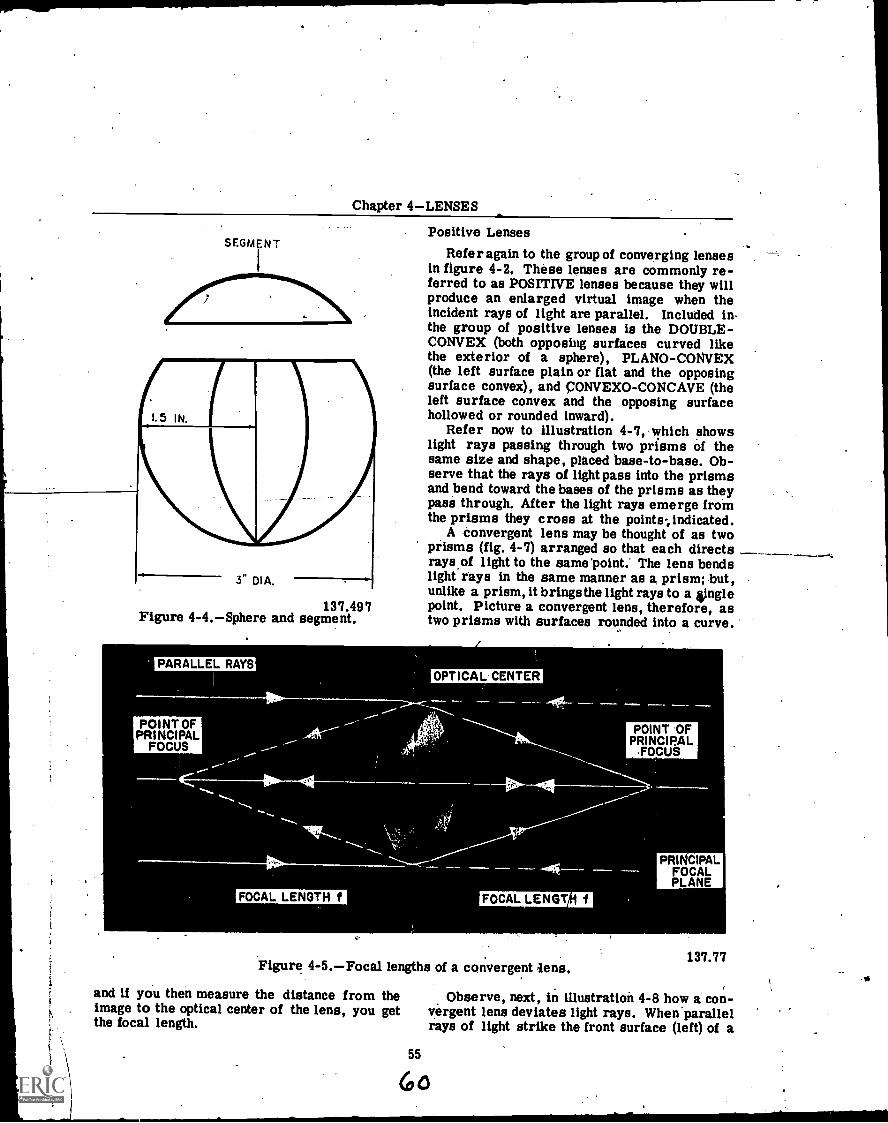
Chapter 4LENSES
SEGMENT
15 IN.
3" DIA.
137.497Figure 4-4.Sphere and segment.
Positive LensesRefer again to the group of converging lenses
in figure 4-2. These lenses are commonly re-ferred to as POSITIVE lenses because they willproduce an enlarged virtual image when theincident rays of light are parallel. Included inthe group of positive lenses is the DOUBLE-CONVEX (both opposing surfaces curved likethe exterior of a sphere), PLANO-CONVEX(the left surface plain or flat and the opposingsurface convex), and CONVEXO-CONCAVE (theleft surface convex and the opposing surfacehollowed or rounded inward).
Refer now to illustration 4-7, which showslight rays passing through two prisms of thesame size and shape, placed base-to-base. Ob-serve that the rays of light pass into the prismsand bend toward the bases of the prisms as theypass through. After the light rays emerge fromthe prisms they cross at the points indicated.
A convergent lens may be thought of as twoprisms (fig. 4-7) arranged so that each directsrays.of light to the same 'point. The lens bendslight rays in the same manner as a prism; but,unlike a prism, it brings the light rays to a ;Inglepoint. Picture a convergent lens, therefore, astwo prisms with surfaces rounded into a curve.
PARALLEL RAYS
POINT OFPRINCIPAL
FOCUS
OPTICAL CENTER
FOCAL LENGTH f FOCAL LENGT f
Figure 4-5.Focal lengths of a convergent lens.
and if you then measure the distance from theimage to the optical center of the lens, you getthe focal length.
55
POINT OFPRINCIPAL
FOCUS
PRINCIPALFOCALPLANE
137.77
Observe, next, in illustration 4-8 how a con-vergent lens deviates light rays. When parallelrays of light strike the front surface (left) of a
6o
1
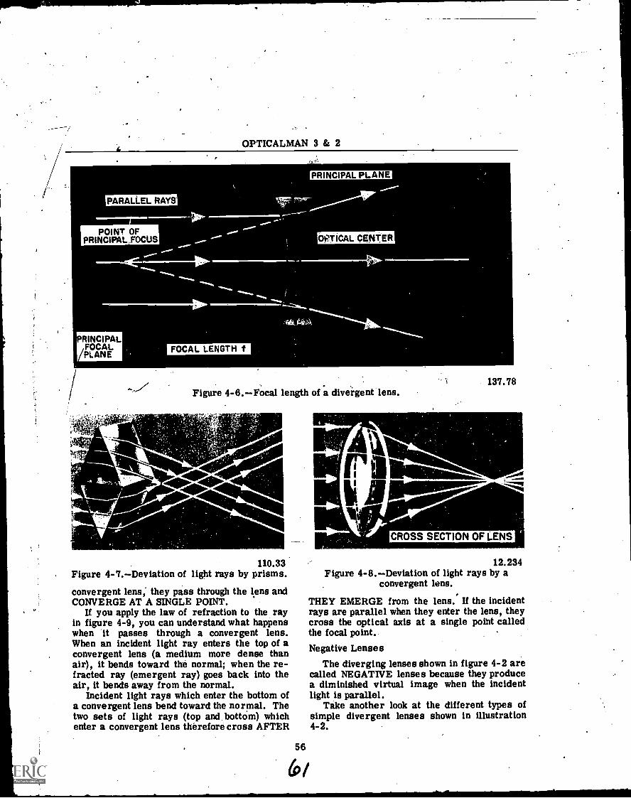
OPTICALMAN 3 & 2
OPTICAL CENTER
137.78Figure 4-6.Focal length of a divergent lens.
.441101'.4000'
_s01.''4111114401%
110.33Figure 4-7.Deviation of light rays by prisms.
convergent lens; they pass through the lens andCONVERGE AT A SINGLE POINT.
If you apply the law of refraction to the rayin figure 4-9, you can understand what happenswhen *it passes through a convergent lens.When an incident light ray enters the top of aconvergent lens (a medium more dense thanair), it bends toward the normal; when the re-fracted ray (emergent ray) goes back into theair, it bends away from the normal.
Incident light rays which enter the bottom. ofa convergent lens bend toward the normal. Thetwo sets of light rays (top and, bottOm) whichenter a convergent lens therefore cross AFTER
56
(r)
CROSS SECTION OF LENS
12.234Figure 4-8.Deviation of light rays by a
convergent lens.
THEY EMERGE from the lens. If the incidentrays are parallel when they enter the lens, theycross the optical axis at a single point calledthe focal point..
Negative LensesThe diverging lenses shown in figure 4-2 are
called NEGATIVE lenses because they producea diminished virtual image when the incidentlight is parallel.
Take another look at the different types ofsimple divergent lenses shown in illustration4 -2.
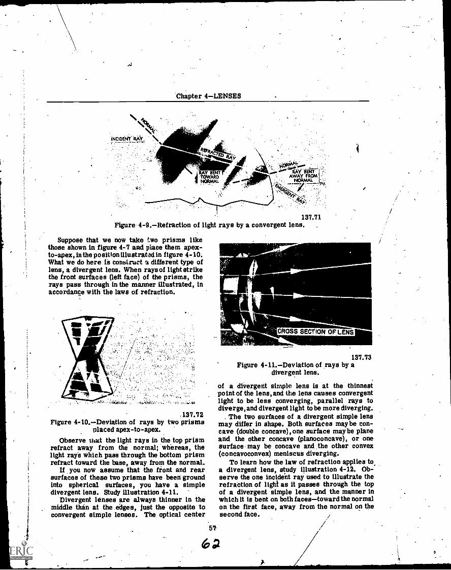
I
Chapter 4LENSES
INCIDENT aki \17,7777'""--"- %
REnticreo
RAY BENT
ORMALTNOW
AL
'ea.' RAY- BENTAWAY FROM I -'
137.71Figure 4-9.Refraction of light rays by a convergent lens.
Suppose that we now take two prisms likethose shown in figure 4-7 and place them apex -to- apex, in the position illustrated in figure 4-10.What we do here is construct a different type oflens, a divergent lens. When rays of light strikethe front surfaces (left face) of the prisms, therays pass through in the manner illustrated, inaccordance with the laws of refraction.
137.72Figure 4-10.Deviation of rays by two prisms
placed apex-to-apex.Observe that the light rays in the top prism
refract away from the normal; whereas, thelight rays which pass through the bottom prismrefract toward the base, away from the normal.
If you now assume that the front and rearsurfaces of these two prisms have been groundinto spherical surfaces, you have a simpledivergent lens. Study illustration 4-11.
Divergent lenses are always thinner in themiddle than at the edges, just the opposite toconvergent simple lenses. The optical center
CROSS SECTION OF LENS
137.73Figure 4-11.Deviation of rays by a
divergent lens.
of a divergent simple lens is at the thinnestpoint of the lens, and the lens causes convergentlight to be less converging, parallel rays todiverge, and divergent light to be more diverging.
The two surfaces of a divergent simple lensmay differ in shape. Both surfaces maybe con-cave (double concave), one surface maybe planeand the other concave (planoconcave), or onesurface may be concave and the other convex(concavoconvex) meniscus diverging.
To learn how the law of refraction applies toa divergent lens, study illustration 4-12. Ob-serve the one incident ray used to illustrate therefraction of light as it passes through the topof a divergent simple lens, and the manner inwhich it is bent on both facestoward the normalon the first face, away from the normal on thesecond face. ./

OPTICALMAN 3 8z 2
HP.
INCIDENT RAYplotpl;dP
": Idgia;
.................
............
it.11
RAY ,.BENT11 TOWARD
lj11111
-NORMAL 101
Figure 4-12. Application of the law'of refraction to a divergent lens.
Light rays which pass through divergentlenses off' the optical axis ALWAYS 'refract,toward the thickest part of the lenses.
IMAGE FORMATION
As you know, light rays in the form of pencilsemanate from all points on an object and passthrough a lens to a point of convergence behindthe lens. This point is called the IMAGE POINTWHEN THE OBJECT IS AT A DISTANCEGREATER THAN THE FOCAL LENGTH OFTHE LENS.
Review at this time illustration 4-9, for itshows how the laws of refriction may be appliedto plot the path of any light ray through anytypes of lens. Then study illustration 4-13,which shows how light rays pass through a con-vergent lens and converge at a single point.
Millions of light rays may come from everypoint of light on an object, but we use in illustra-tion 4-43 only three such rays to show how theypass through a convergent lens. As you learnedpreviously .in this chapter, the light rays whichstrike a convergent lens on either side of theoptical axis bend toward the thickest part of thelens, and bend again toward the thickest part ofthe lens when they emerge from it. As shownin the illustration, they converge at a singlepoint.
A light ray which passes along the opticalaxis through a lens does not bend, because it
137.74
strikes the surfaces of the lens at and parallelto the normal.
Study illustration 4-13 carefully. The centralray in the top portion (A) of this illustrationpasses through the optical center and does notrefract as it continues through the lens. Theotheilight rays (2) refract toward the thickestportion of the lens as they enter it, and as theyemerge, and form an INVERTED and RE-VERTED image (F) at the IMAGE PLANE. Theother part of F is on the optical axis.
The image is inverted and reverted becausetwo similar rays from a point at the bottom ofthe object form a point of the image correspond-ing to the bottom of the object; and every pointon the object fortis its point of light on theimage in the same manner.. Rays from theupper part of , the object form points of light onthe corresponding image, thereby causing theimage to, be transposed diametrically and sym-metrically 'across the optical axis from theobject. THIS IMAGE IS REAL.
Principal RaysRefer now to illustration 4-14 which shows
the FOUR PRINCIPAL RAYS of light whichpass through any ',ens, 'ItICK pr THIN. Whenthese light rays pass through a lens, they AL-WAYS follow the rules which pertain to each.Line XY in the illustration is the optical axis(sometimes called principal axis) of the lens.
58
63
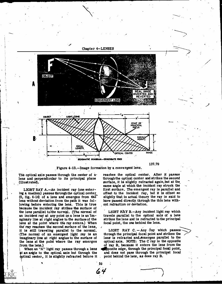
Chapter 4LENSES
t
OBJECT
OBJECT LIGHT coW
CONVERGENT LENS
REAL IMAGEINVERTED ANDREVERTED
w<ffe#
#
PRINCIPALPOINT OF
FOCUS
1:4 d)1P
4AfAIPAPIiir
ffW poI NT
LENGTH. 441IM.
FoCAL
XOPTICAL CENTER
SOIDAATIC DIAGRAM - CONJUGATE POO
Figure 4-13.Image formation by a convergent lens.
The optical axis passes through the center of alens and perpendicular to its principal plane(illustrated).
LIGHT RAY A.An incident ray (one enter-ing a medium) passes through the optical center(0, fig. 4-14) of a lens and emerges from thelens without deviation from the path it was fol-lowing before entering the lens. This is truebecause the incident ray strikes the surface ofthe lens parallel tolthe normal. (The normal ofan incident ray at any point on a lens is an Im-aginary line at right angles to, the surface of thelens at the point where the ray enters.) Whenthd ray reaches the second surface of the lens,it is still traveling parallel to the normal.(The normal of an emergent light ray is animaginary line at right angles to the surface ofthe lens at the point where the ray emergesfrom the lens.)
When an "A" light ray passes through a lenst an angle to the optical. axis but through theptical center, it is slightly refracted before it
IMAGE
137.79
reaches the optical center. After it passesthrough the optical center and strikes the secondsurface, it is slightly refracted again,but at thesame angle at which the incident ray struck thefirst surface. The emergent ray is parallel andoffset to the incident ray, but it is offset soslightly that in actual theory the ray is said tohave Passed directly.. through the thin lens with-opt refraction or deviation.
LIGHT FLAY B.Any incident light ray whichtravels parallel to the optical axis of a lensstrikes the lens and is refracted to the principalfocal point, the one behind the lens.
LIGHT RAY C. Any riay which passesthrough the principal focal point and strikes the /-lens. is refracted andAmerges parallel to theoptical axis. NOTE: The C ray is the oppositeof 'ray B, because it enters the lens from the
irnposite edge, through the principal focal point,and does not pass through the principal focalpoint behind the lens, as does ray B.
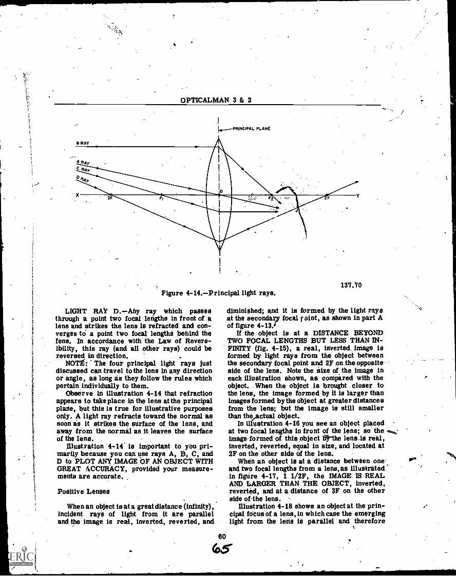
OPTICALMAN 3 & 2
.1
14---PRINCIPAL PLANE
Figure 4-14.Principal light rays.
LIGHT RAY D.Any ray which passesthrough a point two focal lefigths in front of alens and strikes the lens is refracted and con-verges to a point two focal lengthri behind thefens. In accordance with the Law of Revers-ibility, this ray (and all other rays) could bereversed in direction.
NOTE: The four principal light rays justdiscussed can travel to the lens in any directionor angle, as long as they follow the rules whichpertain individually to them.
Observe in illustration 4-14 that refractionappears to take place in the lens at the principalplane, but this is true for illustrative purposesonly. A light ray refracts toward the normal assoon is it strikes the surface of the lens, andaway from the normal as it leaves the surfaceof the lens.
Illustration 4-14. is important to you pri-marily because you can use rays A, B, C, andD to PLOT ANY IMAGE OF AN OBJECT WITHGREAT ACCURACY, provided your measure-ments are accurate.
Positive Lenses
When an object is at a great distance (infinity),incident rays of light from it are paralleland the image is real, inverted, reverted, and
60
137.70
diminished; and it is formed by the light raysat the secondary focal r oint, as shown in part Aof figure 4 -13.
If the object is at a DISTANCE BEYONDTWO FOCAL LENGTHS BUT LESS THAN IN-FINITY (fig. 4-15), a real, inverted. image isformed by light rays from the object betweenthe secondary focal point and 2F,on_theopposite-side of the lens. Note the size of the image ineach illustration shown, as compared with theobject. When the object is brought closer tothe lens, the image formed by it is larger thanimages formed by the object at greater distancesfrom the lens; but the image is still smallerthan theActual object.
In illustration 4-16 you see an object placedat two focal lengths in front of the lens; so theimage. formed of this object 133rthe lens.is real,inverted, reverted, equal in size, and located at2F on the other side of the lens.
When an object is at a distance between oneand two focal lengths from a lens, as illustratedin fighre 4-17, 1 1/2F, the IMAGE IS REALAND LARGER THAN THE OBJECT, inverted,reverted, and at a distance of 3F on the otherside of the lens.
Illustration 4-18 shows an object at the prin-cipal fotus of a lens, in which case the emerginglight from the lehs is parallel and therefore
65-
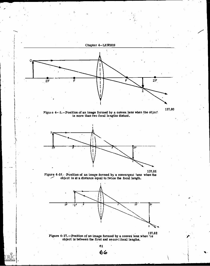
2F
Chapter 4LENSES
Figure 4- ,5.Position of an image formed by a convex lens when the °f eck.is more than two local lengths distant.
137.81Figure 4-16. Position of an image formed by a convergent lens when the
,"" object is at a distance equal to twice the focal length.
137.82Figure 4-17.Position of an image formed by a convex lens when
object is between the first and seconl focal lengths.
137.80
A
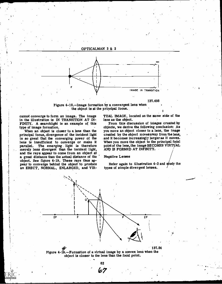
3
OPTICALMAN 3 Si 2
00
tiIMAGE IN TRANSITION
Figure 4-18.Image formation by a.convergent lens whenthe object is at the principal focus..
cannot converge to form an image. The imagein the illustration is IN TRANSITION AT IN-FINITY. A searchlight is an example of thistype of image formation.
When an object is closer to a lens than theprincipal focus, divergence of the incident lightis so great that the converging power of thelens is insufficient to converge or make itparallel. The emerging - light is thereforemerely less divergent than the incident light,and the rays appear to come from an object ata great distance than the actual distance of theobject. See figure 4-19. These rays thus ap-pear to converge behind the object to producean ERECT, NORMAL., ENLARGED, and VIR-
2F
137.498
TUAL IMAGE, located on the same side of thelens as the object.
From this discussion of images created byobjects, we derive the following conclusion: Asyou move an object closer to a lens, the imagecreated by the object moves away from the lens',and it becomes increasingly larger as it moves.When you move the object to the principal fo611point of the lens, the image BECOMES VIRTUALAND IS FORMED AT INFINITY.
Negative Lenses
Refer again to illustration 4-2 and study thetypes of simple divergent lenses.
(11,P137.84
Figure 4-19.Formation of a virtual image by a convex lens when theobject is closer to the lens than the focal point.
62
6,7

Chapter, 4LENSES
Divergent lenses haVe negative dioptricstrength, and they are always thinner in themiddle than at the edges. The optical center ofa divergent lens is at the thinnest, point of theLens, and the lens diverges parallel rays of light.
The point of principal, focus, focal points,and focal planes resulting from the nearnesabfan object or light source to a simple divergentlens are located on the aside of the lens towardthe light source or object. The pqintof prindipalfocus and other focal points are located wherethe emergent rays should interaect',A)n the,optical axis if they were extended backward asimaginary lines toward the side of the lens on
which the light strikes. Review figure 4-6 forsome terminology and focal length of a simpledivergent lens.'
If you use a page of this book as an object-it.at arm's lengthand look at it through Itgent lens, this is what happens:
1. When the lens is in contact with the page(object), the image you_ see, is erect;. normal,and slightly smaller r-than the bbjeCi.
- 2. If you move the lens closer to your eye,the image becomes even smaller.
3. When you have the lens quite close toyour eye, you can see only a blur, REGARDLESSOF THE POSITION IN WHICH YOU HOLD THEOBJECT.
You Will understand what took place whenyou held the divergent lens in the positionsAustdescrihet1 and looked at the page after you studythe neidIew pages, dealinpvith the, constructionof a divergent lens and image formation by 4.1,
. Suppose, now, that we construct a divergentlens like the one shown inIigure 4-6. Proceedas follows: ,
1. Sketch the cibuble6oncave lens on paper.2. Draw a dotted line through the middle of
both ends of the lens, to represent the PRINCI-PAL PLANE.
3. Then draw a straight line through theOPTICAL CENTER of the lens,,PERPENDICU-LAFt TO THE PRINCIPAL PLANE, to representthe OPTICAL AXIS.
4. Next, draw two lines, to represent raysof light, near the ends of the lens to the left face,through the lens (refraction indicated), and outinto space.
5. With your,`vuler, draw the dotted linesalong the straight portion of the emergent lightray to the optical axis. Where the two dottedlines intersect the optical axis is the POINT OFPRINCIPAL FOCUS, as indicated by the terini-nology-and arrow.
6. Draw a dotted line downward from thePOT OF PRINCIPAL FOCUS, and then drawthe tiro arrows in thepositions indicated and in-sert FOCAL LENGTH.
"';.;. -Now sketch another double concave lens on. 'paper (fig. 4-20) and draw a line through the
OPTICAL CENTER, perpendicular with thePRINCIPAL PLANE, to represent the OPTICALAXIS. Then draw' two other lines (parallel)above and below the optical axis, as shown, to'represent FOUR LIGHT RAYS. ,
The light rays you just drew show thePROCEDURE for TRACING LIGHT RAYS'THROUGH A 'DIVERGENT LENS..-Rays whichpass along the optical axis and through theoptical center dO not refract (deviate), as youknow; rays which pass through the lens at pointsother than through the optical center are deviatedin the manner shown in the illustration.
When you look through a divergent lens (fig.4-20), extensions of the refracted rays of lightappear to converge at a point, . (POINT OFPRINCIPAL FOCUS) on the same side of thelens as the object, as shown in illustration 4-6.In order-to learn how an image is created by adivergent lens of this type, draw (sketch) thelens on paper and then do the following:
1. Draw a dotted line through the middle ofeach end of the lens to represent the principalplane.
2, Draw another dotted line perpendicular tothe 'principal plane and through the opticalcenter to represent the optical axis. See figure.4-21.
3. Using a focal length of 2 inches, put a doton the _optical axis tcfrepreserit the focal point(F).
4. Next, draw 3 arrows 1 inch high on theoptical axis in the positions indicated by 01,02, and 03. Observe that one arrow is INSIDETHE FOCAL POINT (F), one arrow is ON THE'FOCAL POINT,and the third arrow is BEYONDTHE FOCAL POINT.
5. Along the tips of the arrow heads, drawa line to the principal plane 'to represent a
' parallel ray of light (parallel to the opticalaxis). Note how this ray diverges up after itcontacts, the principal plane. If you were to lookat this ray from the opposite side of the lens,' itwould appear to emerge from the first focalpoint; so extend this line (dotted portion) to thefocal point (F).
6. At the-point where the ray of light whichpasses through the optical center irom arrow01 intersects the dotted extension to the focal
63
ZE
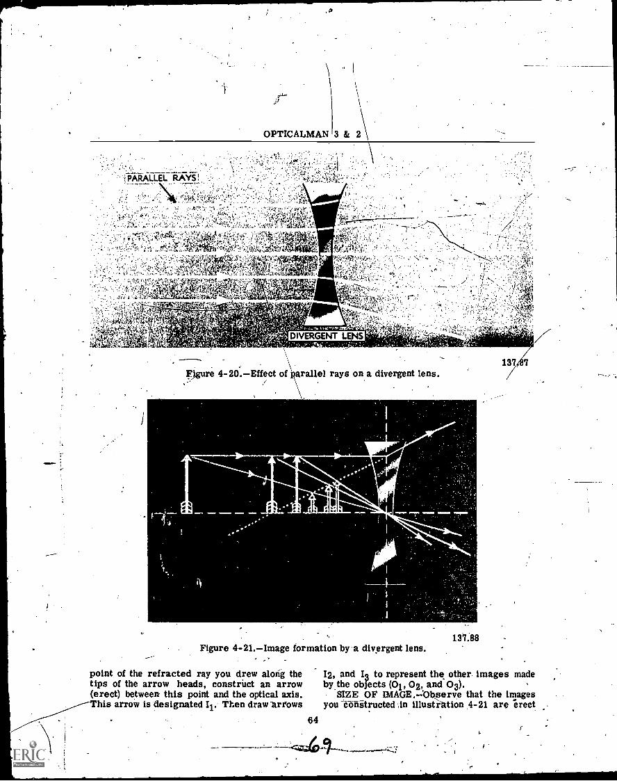
OPTICALMAN
10
3& 2
.1 :.
. T-,...,,-.',1 .... ..:: ,r !:...... :. ..-',.,....-.7:::..-:..,.........:.;(pi.,..-..:......f,-1." i.. %,,':,,k1IF:Atitci',1
. 2, ,f.)..1:. ,..'' i:'...: .:.. ...,..;,.......,r;.1 /-*Po 41' ,-.-ty:...1... , , .:. 4,?1,,h,,,,..
4 ''.. 'C.
". '... 1.,'::-:',.;, 1;. '..; :I .:.,t6,..;::::"7.:::::71..-A, It'll',/,i-!.. '0 ..',:'24:.trt..,0,....4.RO:k.''',''' ' . :..-4.2-.....:'-...tikl'.*)fif4..,itri
i'
,......,, ..,,.........',,
,...
.1':".;"-. :...,....','..,,y,r;!4";,'-';;(.1.41.t.''.4i.'''.;r1,141..::::.,,I,',:t,',..,
.,, ..:, . .:; - .,.,t,. ;-?6,/..+&.,.i.3! ,,,,,;,;,44,, ,.....,/ .i.
; .:-. ' ff..tiZA114,;..14,' );:. ,...:,.,:p.4 -1 tt .4..,z.1,;-ra..
,..
..:.,',::',...,....lik:-.Iik''''',.*" ?...:..,,,,4.. -,....s 7.: (3:;.1e,: 1.::10 .,..t...;.:.tr,' ck,k. ' 'i*
.,'...'', fl
137 7
Figure 4-20.Effect of araliel rays on a divergent lens.
j:ir1,1111°
Figure 4-21.Image formation by a divergent lens.
point of the refracted ray you drew along thetips of the arrow heads, construct an arrow(erect) between this point and the optical axis.This arrow is designated I. Then draw ariows
64
137.88
12, and I; to represent the other images madeby the objects (01, 02, and 03).
SIZE OF IMAGE.-0bserve that the imagesyou obatructed in illusfiAtion .4-21 are erect
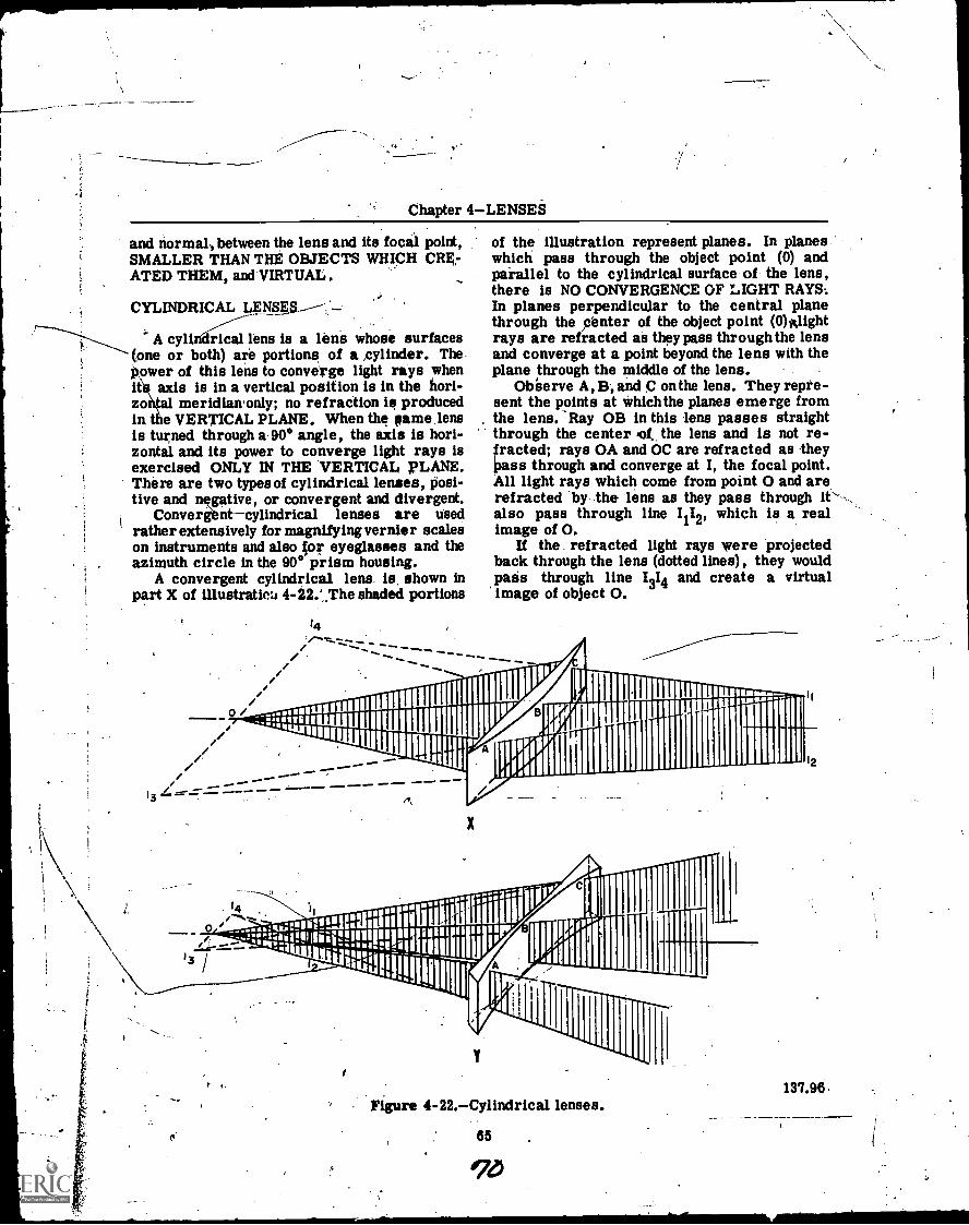
Chapter 4LENSES
and normal, between the lens and its focal point,SMALLER THAN THE OBJECTS WHICH owATED THEM, and VIRTUAL.
CYLINDRICAL LgNsgs,--:-
A cylindrical lens is a lens whose surfaces(one or both) are portions of a cylinder. The.Power of this lens to converge light rays whenit axis is in a vertical position is in the hori-zo meridiaironly; no refraction is producedin e VERTICAL PLANE. When the same lensis turned through a 90° angle, the axis is hori-zontal and its power to converge light rays isexercised ONLY IN THE VERTICAL, PLANE.There are two types of cylindrical lenses, posi-tive and negative, or convergent and divergent.
Conver&ntcylindrical lenses are usedrather extensively for magnifying vernier scaleson instruments and also or eyeglasses and theazimuth circle in the 90° prism housing.
A convergent cylindrical lens is. shown inpart X of illustration 4 -22.', The shaded portions
14."o
13 "401 114;;;i'"I"14111141111111k
14
/
of the illustration represent planes. In planeswhich pass through the object point (0) andparallel to the cylindrical surface of the lens,there is NO CONVERGENCE OF LIGHT RAYS:In planes perpendicular to the central planethrough the center of the object point (0)Alightrays are refracted as they pass through the lensand converge at a point beyond the lens with theplane through the middle of the lens.
Obeerve A, B; and C on the lens. They repre-sent the points at which the planes emerge fromthe lens. Ray OB in this lens passes straightthrough the center Pot. the lens and is not re-fracted; rays OA and OC are refracted as theyPass through and converge at I, the focal point.All light rays which come from point 0 and arerefracted by .the lens as they pass through it` -,also pass through line 1112, which is a realimage of 0.
If the refracted light rays were projectedback through the lens (dotted lines), they wouldpass through line 1314 and create a virtualimage of object 0.
01111111-"P I II
ijimm IPr irior
16 PAM 1111
Ilupt ,-
MIM MM. M, N MM.
X
,
Figure 4-22.Cylindrical lenses.
65
qb
12
137.96.
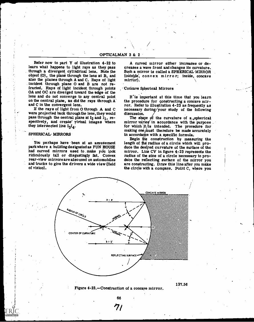
OPTICALMAN 3 & 2
Refer now to part Y of illustration 4-22 tolearn what happens to light rays as they passthrough a divergent cylindrical lens. Note theobject (0), the plane through the lens at B, andalso the planes through A and C. Rays of lightincident through plane 0 and B are not re-fracted. Rays of light incident through pointsOA and OC- are diverged toward the edge of thelens and do not converge to any central pointon the central plane, as did the rays through Aand C in the convergent lens.
If the rays of light from 0 through A and Cwere projected back through the lens, they wouldpass through the central plane at 12 and Il, re-spectively, and creme'` virtual images wherethey intersected line 1314.
SPHERICAL, MIRRORS
You perhaps have -been at an amusementpark where a building designated as FUN HOUSEhad curved mirrors used to . make yOu lookridiculously tall or disgustingly fat. Convexrear-view mirrors are also used on automobilesand trucks to give the drivers a wide view (fieldof vision).
A curved mirror either increases or de-creases a wave front and changes its curvature.Such a mirror is called a SPHERICAL-MIRROR(outscle, cony ex mirr o r; inside, concavemirror). ,\
'Concave Spherical Mirrors
'Cis important at this time that you learnthe procedure for constructing a concave mir-ror. Refer to illustration 4-23 as frequently asnecessary during /your study of the followingdiscussion.
The shape f the curvature of a 4sphericalmirror varie in accordance with the purposefor which '1t is intended. The procedure formaking one\ ust therefore be made accuratelyin accorda pe with a specific formula.
Begin e construction by measuring thelength of 6 radius of a circle which will pro-duce the desiFed curvature of the surface of themirror. Line CV in figure 4 -23 represents theradius of the size of a circle necessary to pro-duPe the reflecting surface of the mirror youare constructing. Draw this line after you makethe circle with a compass. Point C, where you
CONCAVE MIRROR
137.56Figure 4-23.Conatruction of a concave mirror.
66
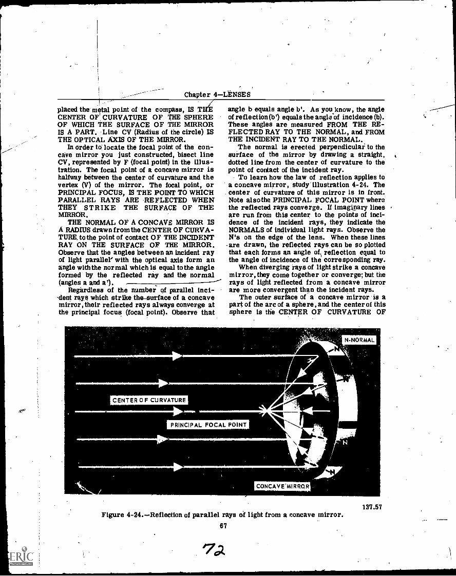
Chapter 4 LENSES
placed the metal point of the compass, IS TCENTER OF CURVATURE OF THE SPHEREOF WHICH THE SURFACE OF THE MIRRORIS A PART. Line CV (Radius of the circle) ISTHE OPTICAL AXIS OF THE MIRROR.
In order to locate the focal point of the con-cave mirror you just constructed, bisect lineCV, represented by F (focal point) in the illus-tration. The focal point of a concave mirror ishalfway between the center of curvature and thevertex (V) of the mirror. The focal point, orPRINCIPAL FOCUS, IS THE POINT TO WHICHPARALLEL RAYS ARE REFLECTED WHENTHEY STRIKE THE SURFACE OF THEMIRROR,
THE NORMAL OF A CONCAVE MIRROR ISA RADIUS drawn from the CENTER OF CURVA-TURE, to the point of contact OF THE INCIDENTRAY ON THE SURFACE OF THE MIRROR.Observe that the angles between an incident rayof light parallel with the optical axis form anangle with the normal which is equal to the angleformed by the reflected ray and the normal(angles a and a').
Regardless of the number of parallel inci-dent rays which strike the-surface of a concavemirror, their reflected rays always converge atthe principal focus (focal point). Observe that
angle b equals angle b'. As you know, the angleof reflection (b') equals the angle of incidence (b).These angles are measured FROM THE RE-FLECTED RAY TO THE NORMAL, and FROMTHE INCIDENT RAY TO THE NORMAL.
The normal is erected perpendicular to thesurface of the mirror by drawing a straight,dotted line from the center of curvature to thepoint of contact of the incident ray.
To learn how the law of reflection applies toa concave mirror, study' illustration 4-24. Thecenter of curvature of this mirror is in front.Note also the PRINCIPAL FOCAL POINT wherethe reflected rays converge. If imaginary linesare run from this center to the points of inci-dence of the incident rays, they indicate theNORMALS of individual light rays. Observe theN's on the edge of the lens. When these linesare drawn, the reflected rays can be so plottedthat each forms an angle of reflection equal tothe angle of incidence of the corresponding ray.
When diverging rays of light strike a concavemirror, they come together or converge; but therays of light reflected from a concave mirrorare more convergent than the incident rays.
The outer surface of a concave mirror is apart of the arc of a sphere, and the center of thissphere is the CENTER OF CURVATURE OF
CENTER OF CURVATURE
PRINCIPAL FOCAL POINT
N-NORMAL
%En\ICONCAVE'MIRRQR
137.57Figure 4-24.Reflection of parallel rays of light from a concave mirror.
67
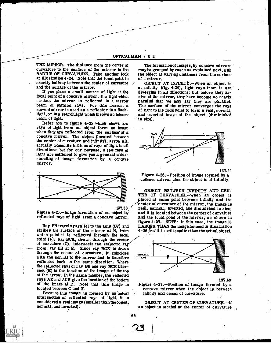
OPTICALMAN 3 & 2
THE MIRROR. The distance from the center ofcurvature to the surface of the mirror is. theRADIUS OF CURVATURE. Take another lookat illustration 4-24. Note that the focal point isexactly halfway between the center of curvatureand the surface of the mirror.
If you place a small source of light at thefocal point of a concave mirror, the light whichstrikes the mirror is reflected in a narrowbeam of parallel rays. For this _reason, acurved mirror is used as a reflector in a flash-light, or in a searchlight which throws an intensebeam of light.
Refer now to fig re 4-25 which shows. howrays of light from an objectform- an-imagewhen they are reflected from the surface' of aconcave mirror. The object (located betweenthe center of curvature and infinity), arrow AB,actually transmits billions of rays of light in alldirections; but for our purpose, a few rays oflight are sufficient to give you a general under-standing of image formation by a concavemirror.
197.58Figure 4-25.Image formation of an object byreflected rays of light from a concave mirror.
Ray BH travels parallel to the axis (OV) andstrikes the surface of the mirror at H, fromwhich point it is reflected through the focalpoint (F)-- Ray BCK, drawn through the centerof curvature (C), intersects the reflected rafrom ray BH at E. Since ray BCK is drawnthrough the center of curvature, it coincideswith the normal to the mirror and is thereforereflected back in the same direction. Wherethe reflected rays of ray BH and ray BCK inter-sect (E) is the location of the image of the topof the arrow. In the saute manner, the reflectedrays AK and ACH give the location of the bottomof the image at D. Note that this image islocated between and F.
Because this image is formed by an actualintersection of reflected rays of light, it isconsidered a real image (smaller than the object,normal, and inverted).
The formationof images, by concave mirrorsmay be grouped by cases as explained next, withthe object at varying distances from the surfaceof a mirror.
OBJECT AT INFINITtWhen an object isat infinity (fig. 4-26), light rays from it arediverging in all drrectiOns; but before they ar-rive at the mirror, they have become so nearlyparallel that we may say they are parallel.The surface of the mirror converges the raysof light to the focal point to form a real, normal,and inverted image of the object (diminishedin size).
PRINCIPALAXIS
137.59Figure 4-26.Position of image formed by aconcave mirror when the object is at infinity.
OBJECT BETWEEN INFINITY AND CEN-TER OF CURVATURE.When an object isplaced at some-point between infinity and the
/Center of curvature of the mirror the image isreal, normal, inverted, and diminished in size;and it is located between the center of curvatureand the focal point of the mirror, as shown infigure 4-27. NOTE: In this case, the image ISLARGEXt THAN the image formed in illustration4- 26, iiut it is still smaller than the actual object.
PRINCIPALAX IS
..
137.60Figure 4-27.Position of image formed by a
concave mirror when the object is betweeninfinity and center of curvature.
68
OBJECT AT CENTER OF CURVATURE.Ifan object is located at the center of curvature
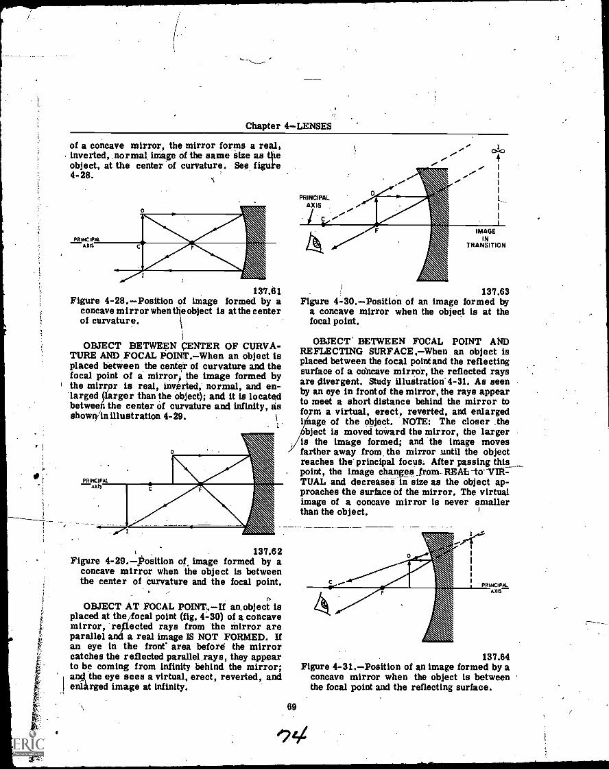
r.
Chapter 4LENSES
of a concave mirror, the mirror forms a reelsinverted, normal image of the same size as tileobject, at the center of curvature. See figuke4- 28.
137.61Figure 4-28.Position of image formed by a
concave mirror when ti e object is at the centerof curvature.
OBJECT BETWEEN VENTER OF CURVA-TURE AND FOCAL POINT.When an object isplaced between the center of curvature and thefocal point of a mirrors the image formed bythe mirrpr is real, inverted, normal, and en-larged (larger than the object); and it is locatedbetween the center of curvature and infinity, asshowlYin illustration 4-29.
PRINCIPALAXIS
OEM137.62
Figure 4-29.Position of image formed by aconcave mirror when the object is betweenthe center of curvature and the focal point.
0OBJECT AT FOCAL POINT. If an, object is
placed at the ocal point (fig. 4-30) of a concavemirror, re ,reflected rays from the mirror areparallel a a real image IS NOT FORMED. Ifan eye in the front' area before the mirrorcatches the reflected parallel rays, they appearto be coming from infinity behind the mirror.anci the eye sees a virtual, erect, reverted, andenlarged image at infinity.
69
PRINCIPALAXIS
C
IMAGEIN
TRANSITION
137.63Figure 4-30.Position of an image formed by
a concave mirror when the object is at thefocal point.
OBJECT' BETWEEN FOCAL POINT ANDREFLECTING SURFACE, When an object isplaced between the focal point and the reflectingsurface of a concave mirror, the reflected raysare divergent. Study illustration.4-31. As seenby an eye in front of the mirror, the rays appearto meet a short distance behind the mirror tofo m a virtual, erect, reverted, and enlargedi age of the object. NOTE: The closer thebject is moved toward the mirror, the larger
is the image formed; and the image movesfarther away from, the mirror until the objectreaches the principal focus. After passing thispoint, the image changes _from- REALto-VTR-TUAL and decrease:3 in size as the object ap-proaches the surface of the mirror. The virtualimage of a concave mirror is never smallerthan the object.
137.64Figure 4-31.Position of an image formed by a
concave mirror when the object is betweenthe focal point and the reflecting surface.

OPTICALMAN 3 & 2
Convex Mirror
Illustration 4-32 shows the procedure forconstructing a convex mirror. Note the anglesof incidence and the angles of reflection formedby the parallel rays of light which strike themirror. These angles are equal, as you know;and'the normals from the center of curvatureof the mirror bisect these two angles. Observethe radius of the circle; all normals to the faceof the mirror are actually radii of the circle.THE PRINCIPAL FOCUS OF A CONCAVEMIRROR IS REAL; THE PRINCIPAL FOCUSOF A CONVEX-MROR IS VIRTUAL.
LIGHTSOURCE
130
1.1
F IMAGE
,zeCENOTFER
/ CURVATURE
000
.137.67Figure 4-32.Procedure for constructing a
convex mirror.
Illustration 4-33shows how rays of lightstrike and reflect from, the surface of a convexmirror. Note the angles formed by reflectedrays, the radius to the center of curvature, thenormals in relation to the radii, and the posi-tion of the virtual image formed by the exten-sions behind the mirror of the reflected raysof light. Now take another look at illustration4-33, which shows rays of light striking dif-ferent portions of the surface of a convex spher-ical mirror. The principle of reversibility isillustrated by the central ray.
The law of reflection holds true for allsurfacesconvex, concave, and plane. Theamount of reflected light from curved surfacesdepends upon the distance of the light source andthe amount of curvature of the reflecting surface.
IC-NORMAL
CURVATURE
137.499Figure 4-33.Reflection of light rays by a
spherical mirror.
70
If light from a distance source such as thesun strikes a convex mirror, the rays are re-flected in a convergent manner. The reason forthis can be determined by plotting the angles ofreflection of individual rays in relation to theirangles of incidence and the normals for eachlight ray. In this case, the normal for each rayis an imaginary line drawn FROM THE CENTEROF CURVATURE OF THE MIRROR TO THEPOINT OF INCIDENCE OF THE RAY. -Theangle of reflection, of course, is equal to theangle of incidence for each ray.
When a light source is close to a mirror, therays are divergent when they strike the mirrorand are also reflecte n a divergent manner.In this case, the rays e reflected at differentangles from parallel rays of light which strikethe mirror, but always equal to the angle ofincidence.
Study illustration 4-34, which shows threeobjects (arrows 01, 02, and 03) of the same sizeb tof different distances from a convex spheri-cii mirror. Thede arrows are of the sameh ight >because they are constructed between aline parallel with the optical axis. The ray oflight which passes along the tips -of the threearrows' strikes the mirror and is reflected inthe manner indicated by arrow AF. The dottedextensionof this line behind the mirror contactsthe optical axis at the focal point.
Rays of light from the three arrow heads tothe CENTER OF CURVATURE OF THE MIR-.ROR ARE SECONDARY. AXES, and the imageformed by each lies between them and theoptical axis. (Any straight line which passes
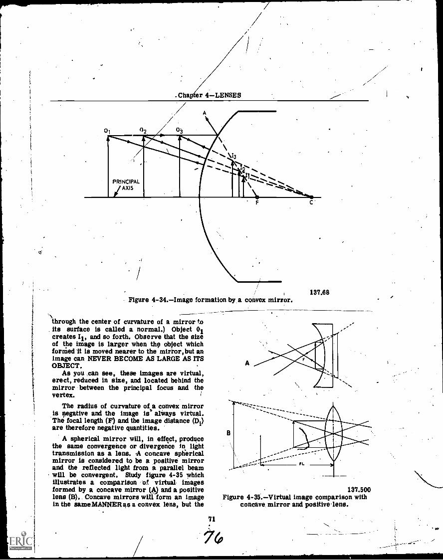
r.
.Cha er 4LENSES
01
PRINCIPAL/AXIS
\\13
".... ."`\............ S 14%.
.... ..... ..4*..... 1. ,I ..... ...... %%eft.... ,z,..........
...4%."...
C
137.68Figure 4-34.Image formation by a convex mirror.
,.t
through the center of curvature of a mirror to. its surface is called a normal.) Object 01creates II, and so forth. Observe that the sizeof the image is larger when thg object whichfornied it is moved nearer to the mirror, but animage can NEVER BECOME AS LARGE AS ITSOBJECT.
As you can see, these images are virtual,erect, reduced in size, and located behind themirror between the principal focus and thevertex.
The radius of curvature of a convex mirroris gegative and the image is always virtual.The focal length (F) and the image distance (Di)are therefore negative quantities.
A spherical mirror will, in effect, producethe same convergence or divergence in lighttransmission as a lens. A concave sphericalmirror is considered to be a positive mirrorand the reflected light from a parallel beamwill be convergent. Study figure 4-35 whichillustrates a comparison at virtual- imagesformed by a concave mirror (A) and a positivelens (B).. Concave mirrors will form an imagein the sameMANNERas a convex lens, but the
137.500Figure 4-35.Virtual image comparison with
concave. mirror and positive-lens.
71
76
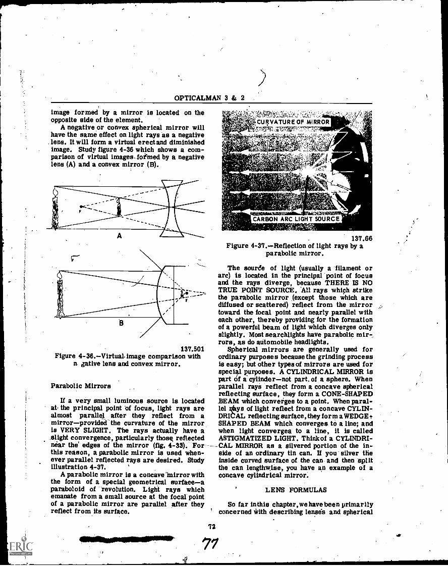
OPTICALMAN 3 & 2
image formed by a mirror is located on theopposite side of the element.
A negative or convex spherical mirror willhave the same effect on light rays as a negative
. lens. It will form a virtual erect and diminishedimage. Study figure 4-36 which shows a com-parison of virtual images. foiemed by a negativelens (A) and a convex mirror (B).
137.501Figure 4-36.Virtual image comparison with
n, dative lens and convex mirror.
Parabolic Mirrors
If a very small luminous source is locatedat the principal point of focus, light rays arealmost parallel after they reflect from amirrorprovided-the curvature of the mirroris VERY SLIGHT. The rays actually have aslight convergence, particularly thos reflectednear the' edges of the mirror (fig. 4-33). Forthis reason, a parabolic mirror is used when-ever parallel reflected rays are desired. Studyillustration 4-37.
A parabolic mirror is a concave mirror withthe form of a special geometrical surface aparaboloid of revolution. Light rays whichemanate from a small source at the focal pointof a parabolic mirror are parallel after theyreflect from its surface.
CURVATURE OF MIRRORN',,M"Iks;,:40.71V7...=7"7:411111
efeffaSlinalafCARBON ARC LIGHT SOURCE
137.66Figure 4-37.Reflection of light rays by a
parabolic mirror.
The source of light (usually a filament orarc) is located in the principal point of focusand the rays diverge, because THERE IS NOTRUE POINT SOURCE. 'All rays which strikethe parabolic mirror (except those which arediffused or scattered) reflect from the mirrortoward the focal point and nearly parallel witheach other, thereby providing for the formationof a powerful beam of light which diverges onlyslightly. Most searchlights have parabolic mirrors, as do automobile headlights.
Spherical mirrors are generally used forordinary purposes because the grinding processis easy; but other types of mirrors are used forspecial purposes. A CYLINDRICAL MIRROR ispart of a cylindernot part. of a sphere. Whenparallel rays reflect from a concave sphericalreflecting surface, they form a CONE-SHAPEDBEAM which converges to a point. When paral-lel kfiys of light reflect from a concave CYLIN-DRICAL reflecting surface, they form a WEDGE tSHAPED BEAM which converges to a line; andwhen light converges to a line, it is calledASTIGMATIZED LIGHT. Think of a CYLINDRI-
--CAL MIRROR as a silvered portion of the in-side of an ordinary tin can. If you silver theinside curved surface of the can and then Splitthe can lengthwise, you have an example of aconcave cylindridal mirror.
72
LENS FORMULAS
So far inthis chapter,we have been primarilyconcerned with describing lensis and spherical
e%)
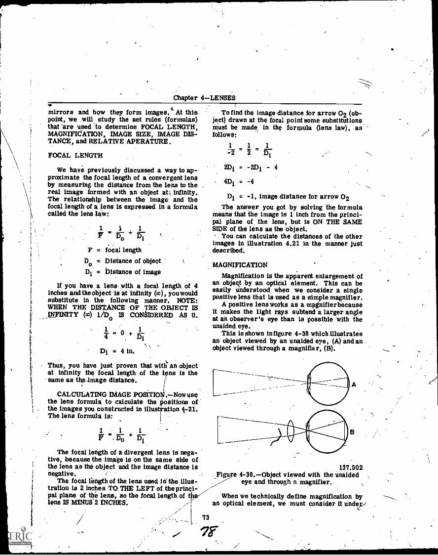
f.
F
Chapter 4LENSES
mirrors and how they form images.4 At thispoint, we will study the set rules (formulas)that 'are used to determine FOCAL LENGTH,MAGNIFICATION, IMAGE SIZE, IMAGE DIS-TANCE, and RELATIVE APERAT.URE.
FOCAL LENGTH
We have previously discussed a way to ap-proximate the focal length of a Convergent lensby measuring, the distanCe from the lens to thereal image formed with an object at;. infinity.The relationship between the image and thefocal length of a lens is expressed in a formtilacalled the lens laiv:
1 1 1
15"; 157
F = focal lengthDo = Distance of objectDi = Distance of image
If you have a lens with a focal length of 4inches andthe object is at infinity (cc), youwouldsubstitute in the following manner. NOTE:.WHEN THE DISTANCE OF THE OBJECT ISINFINITY (co) 1/D0 IS CONSIDERED AS 0.
1 A 1T = +
Di = 4 in.
Thus, you have just proven that with an objectat infinity the focal length of the lens is thesame as the image distance.
I
CALCULATING IMAGE POSiT11
i
.Now usethe lens formula to calculate the positions ofthe images you constructed in 4-21.The lens formula is:
1 1
+ Di
The focal length of a divergent lens is nega-tive, because the image is on the same side ofthe lens as the object and the image distance isnegative.
The focal length of the lens used iri the illus-tration is 2 inches TO THE LEFT of the princi-pal plane of the lens, so the focal length of tfralens IS MINUS 2 INCHES:
O
73
To find the image distance for arrow 02 (ob-ject) drawn at the focal point some substitutionsmust be made in the formula (lens law), asfollows:
1 1 1
-2 2 Di
2Di = -2Di - 4
4Di = -4
Di = -1, image distance for arrow 02The answer you got by solving the formula
means that the image is 1 inch from the princi-pal plane of the lens, but is ON THE SAMESIDE of the lens as the object.
You can calculate the distances of the otherimages in illustration 4.21 in the manner justdescribed.
MAGNIFICATION
Magnification is the apparent enlargement ofan object by an optical element. This can beeasily understood when we consider a singlepositive lens that is used as a simple magnifier.
A positive lens works as a magnifier becauseit makes the light rays subtend a larger angleat an observer's eye than is possible with theunaided eye.
This is shown in figure 4-38 which illustratesan object viewed by an unaided eye, (A) and anobject viewed through a magnifier, (B).
137.502Figure 4-38.Object viewed with the unaided
eye and through a magnifier.
When we technically define magnification byan optical element, we must consider it undep

OPTICALMAN 3 & 2
two conditions of. magnification: LATERAL andANGULAR.
Lateral Magnification
The ratio of the linear size of-the image tothat of the object is LATERAL MAGNIFICATION.
Lateral. magnification of/an image is a varia-ble amount controlled by the. distanCe of theobject to the lens anct/the focal length of thelens. The numerical' relationship between lat-eral magnification and the lens or mirror is--expressed in the following formula:
MSi Di,/ S Doo
This /formula shows that lateral magdification(M) fs equal to the size of the image (Si) dividedby the size of the object (So) and also equal tothe distance,- of the image (Di) divided by the
,/ distance of the object (Do).In order to firmly fix the formulas and the
relationship between focal length magnification,the size and distance of object and image, let'sput the formulas to use by constructing a con-vergent lens on paper.
Draw a convergent lens that is 3 inches highwith .the optical axis and the principal plane.shown by dotted lines. Next, measure off 2inches along the axis on each side of the opticalcenter and mark them with the letter "F" toremind you that they are the focal points. Yourdrawing should now look like figure 4-39. Nowdraw an arrow one inch hightwith its tail on theojOical axis and placed 3 inches to the left ofthe principal plane.
137.503gure 4-39.-Convergent lens,
74
You know, of course, that each point on thearrow is radiating light in all directions, andthat many of the rays will strike the lens. Andyou know that all the rays that reach the lensfrom any point on the object will bend and meetat a corresponding point on the image. So toplot the image of any point on the object, allwe'll have to do is draw two rays, ,and find thepoint-where-they-crofts: Then we'll have thecorresponding point on the image.
To find the image of the arrowhead, draw aray from the arrowhead to the principal planeof the lens, and make the ray parallel to theoptical axis. What do we know about raysparallel to the optical axis? We know that theybend as they pass through the 'lens, and afterthey leave the lens they pass through the prin-cipal focal point on the other side. From thepoint where your first ray meets the principalplane, it will pass through the second focalpoint. So add that refracted ray to your draw-ing. We know that thg. image of the arrowheadis somewhere along that ray. Your drawingshould look like figure 4-40.
137.504Figure 4-40.-Convergent.lens with ray passing
through focal point.
Now, for your other ray, use the one thatpasses through the first focal point. Draw aray from the arrowhead through the first .focal,point, and continue. the ray until it meets theprincipal plane of the lens. (If this line goes .
below the lens you've drawn, don't worry aboutit. This plotting method will work anyway. Justcontinue the line that represents the principalplane until it meets the ray.) What do we knowabout rays passing through the focal point? Weknow that they bend when they pass through thelens, and that they emerge parallel to the axis.So, from the point where your second ray meetsthe principal plane, draw the refracted ray on
79
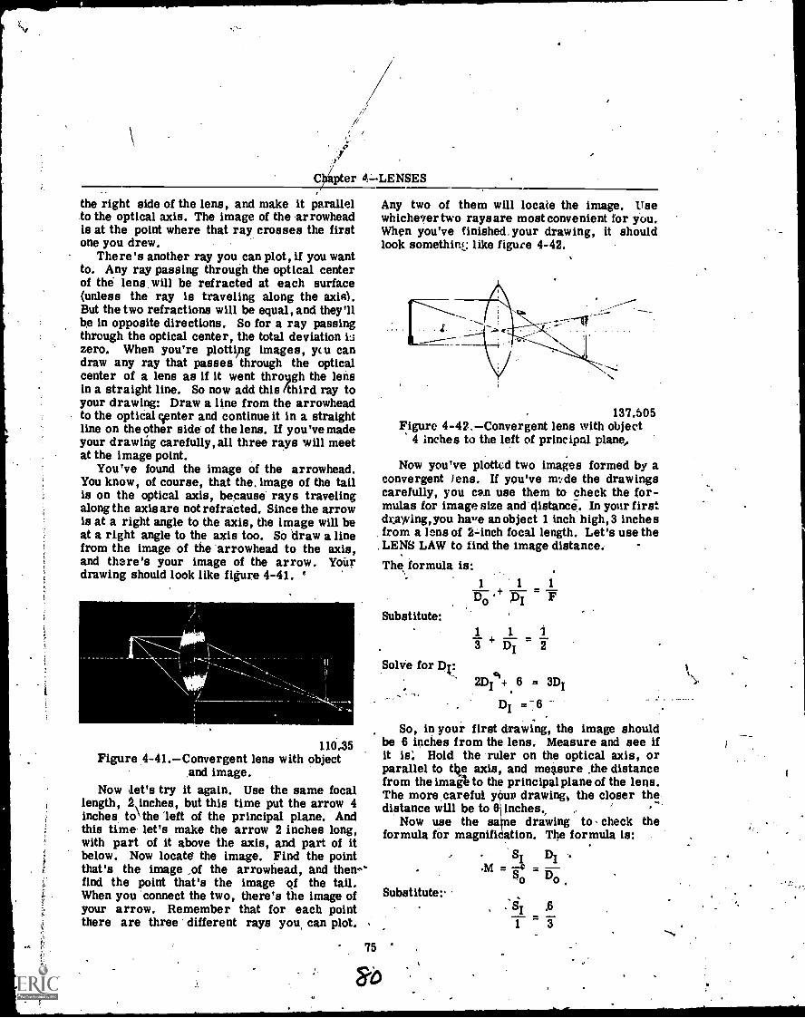
C apter 4=- LENSES
the right side of the lens, and make it parallelto the optical axis. The image of the arrowheadis at the point where that ray crosses the firstone you drew.
There's another ray you can plot, if you wantto. Any ray passing through the optical centerof the lens, will be refracted at each surface(unless the ray is traveling along the axle).But the two refractions will be equal, and they'llbe in opposite directions. So for a ray passingthrough the optical center, the total deviation i3zero. When you're plotti ,ng images, ycu candraw any ray that passes through the opticalcenter of a lens as if it went throligh the lensin a straight line. So now add this (third ray toyour drawing: Draw a line from the arrowheadto the optical center and continue it in a straightline on the other side of the lens. If you've madeyour drawing carefully, all three rays will meetat the image point.
You've found the image of the arrowhead.You know, of course, that the, image of the tailis on the optical axis, because rays travelingalong the axis are not refracted. Since the arrowis at a right angle to the axis, the image will beat a right angle to the axis too. So draw a linefrom the image of the 'arrowhead to the axis,and there's your image of the arrow. Yourdrawing should look like figure 4-41.
110.35Figure 4-41.Convergent lens with object
and image.Now I.et's try it again. Use the same focal
length, 2,inches, but this time put the arrow 4inches to' the left of the principal plane. Andthis time let's make the arrow 2 inches long,with part of it above the axis, and part of itbelow. Now locate the image. Find the pointthat's the image ,of the arrowhead, and thew.'find the point that's the image of the tail.When you connect the two, there's the image ofyour arrow. Remember that for each pointthere are three different rays you, can plot.
Any two of them will locate the image. Usewhichever two rays are most convenient for you.When you've finished. your drawing, it shouldlook somethirtL: like figure 4-42.
137.505Figure 4-42,--Convergent lens with object
4 inches to the left of principal plane,
Now you've plotted two images formed by aconvergent lens. If you've m: de the drawingscarefully, you can use them to check the for-mulas for image size and distance. In your firstdrawing, you have anobject 1 inch high,3 inchesfrom a lens of 2-inch focal length. Let's use theLENS LAW to find the image distance.
The formula is:
Substitute:
Solve for Dv.
1 1
3 4. Di 21
2D14+ 6 = 3D1
DI = -6.
So, in your first drawing, the image shouldbe 6 inches from the lens. Measure and see ifit is Hold the ruler on the optical axis, orparallel to the axis, and measure the distancefrom the imagt to the principal plane of the lens.The more, careful yOuv drawings the closer thedistance will be to I inches.,
Now use the sane e drawing to- check theformula for magnifi ation. The formula is:
Substitute:
75 "
' SiM =
DI
S DSo o
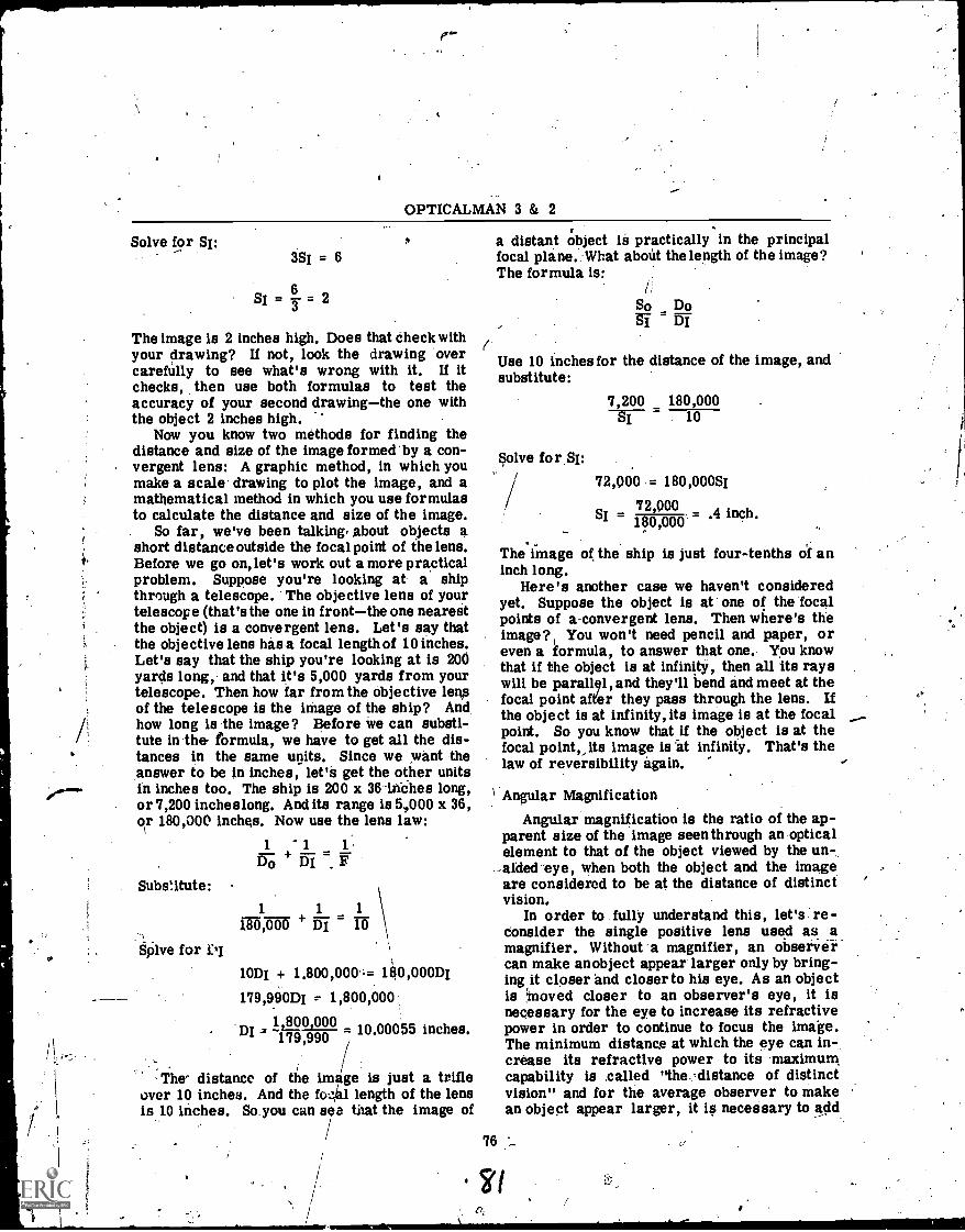
OPTICALMAN 3 & 2
Solve for Si:3S1 = 6
6SI= y 2
The image is 2 inches high. Does that check withyour drawing? If not, look the drawing overcarefully to see what's wrong with it. If itchecks, then use both formulas to test theaccuracy of your second drawingthe one withthe object 2 inches high.
Now you know two methods for finding thedistance and size of the image formed by a con-vergent lens: A graphic method, in which youmake a scale drawing to plot the image, and amathematical method in which you use formulasto calculate the distance and size of the image.
So far, we've been talking. About objects ashort distance outside the focal point of the lens.Before we go on, let's work out a more practicalproblem. Suppose you're looking at a shipthrough a telescope. The objective lens of yourtelescope (that's the one in frontthe one nearestthe object) is a convergent lens. Let's say thatthe objective lens has a focal length of 10 inches.Let's say that the ship you're looking at is 200yards long, and that it's 5,000 yards from yourtelescope. Then how far from the objective lensof the telescope is the image of the ship? Andhow long is the image? Before we can substi-tute in the formula, we have to get all the dis-tances in the same units. Since we want theanswer to be in inches, let'S get the other unitsin inches too. The ship is 200 x 36-.inches long,or 7,200 inches long. And its range is 5,000 x 36,or 180,000 inches. Now use the lens law:
Substitute:
§silve for 1)1
1 '1 1
13O + DI 7.
1 1 1
180,000 + Di
101% + 1.800,00;= 180,000DI
179,990D1 1,800,000',
12_8_00j000 10 00055 inches.-179,990
The' distance of the image is just a trifleover 10 inches. And the fo..141 length of the lensis 10 inches. So you can that the image of
a distant object is practically in the principalfocal plane.What aboUt the length of the image?The formula is:
/1
So Do
(Use 10 inches for the distance of the image, andsubstitute:
76
Solve for SI:
7,200 180,000. 10
72,000 = 180,000S1
7 2,0 00SI = .4 inch.180,000
The image of the ship is just four-tenths of aninch long.
Here's another case we haven't consideredyet. Suppose the object is at one of the focalpoints of a-convergent lens. Then where's theimage?! You won't need pencil and paper, oreven a formula, to answer that one. You knowthat if the object is at infinity, then all its rayswill be parallel, and they'll bend and meet at thefocal point after they pass through the lens. Ifthe object is at infinity, its image is at the focalpoint. So you know that if the object is at thefocal point,, its image is At infinity. That's thelaw of reversibility again.
Angular Magnification
Angular magnification is the ratio of the ap-parent size of the image seen through an opticalelement to that of the object viewed by the un-,-aided eye, when both the object and the imageare considered to be at the distance of distinctvision.
In order to fully understand this, let's re-consider the single positive lens used as amagnifier. Without a magnifier, an observ-ircan make an object appear larger only by bring-ingrit closer and closer to his eye. As an objectis ;moved closer to an observer's eye, it isnecessary for the eye to increase its refractivepower in order to continue to focus the image.The minimum distance at which the eye can in-crease its refractive power to its maximumcapability is called "the.=distance of distinctvision" and for the average observer to makean object appear larger, it is necessary to add.
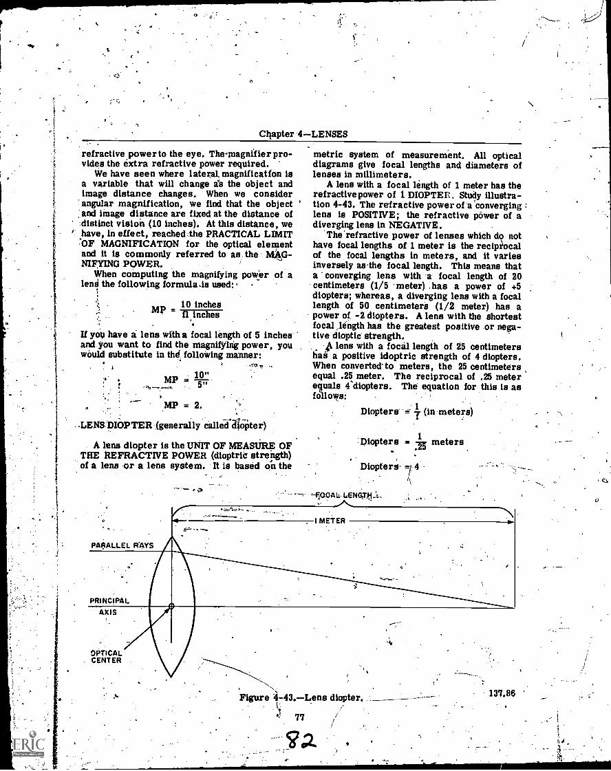
V.
i
Chapter 4LENSES
refractive power to the eye. Thelnagnifier pro-vides the extra refractive power required.
We have seen where lateral. magnification isa variable that will change as the object andimage distance changes. When we considerangular magnification, we find that the objectand image distance are fixed at the distance ofdistinct vision (10 inches). At this distance, we
' have, in effect, reached the PRACTICAL LIMITOF NIAGNIFICATION for the optical elementand it is commonly referred to as-the MAG-NIFYING POWER.
When computing the magnifying power of alene the following formula.is used:
10 inchesfl inches
If you have a lens with focal length of 5 inchesand you want to find the magnifying power, youwould substitute in thd: following manner:
10"=MP 5,,
.
2
MP = 2.
. LENS DIOPTER (generally called diopter)
A lens diopter is the UNIT OF MEASURE OFTHE REFRACTIVE POWER (dioptric strength)of a lens or a lens system. It is based on the
PARALLEL RAYS
metric system of measurement. All opticaldiagrams give focal lengths and diameters oflenses in millimeters.
A lens with a focal length of 1 meter has therefractive power of 1 DIOPTER. Study illustra-tion 4-43. The refractive power of a converginglens is POSITIVE; the refractive power of adiverging lens in NEGATIVE.
'The 'refractive power of lenses which do nothave focal lengths of 1 meter is the recipiocalof the focal lengths in meters, and it variesinversely as-the focal length. This means thata converging lens with a focal length of 20centimeters (1/5 meter) .has a power of +5diopters; whereas, a diverging lens with a focallength of 50 centimeters (1/2 meter) has apower of -2 diopters. A lens with the shortestfocal length has the greatest positive or nega-tive dioptic strength.
lens with a focal length of 25 centimetershas a positive idoptric strength of 4 diopters.When converted to meters, the 25 centimetersequal .25 meter. The reciprocal of .25 meterequals 4'diopters. The equation for this is asfollows:
Diopters 1 (in meters)f
1
5Diopters =
.2meters
Diopters -1 4
I METER
PRINCIPALAXIS
OPTICALCENTER
Figure 4743.Lens diopter.I.
77
137.86 '
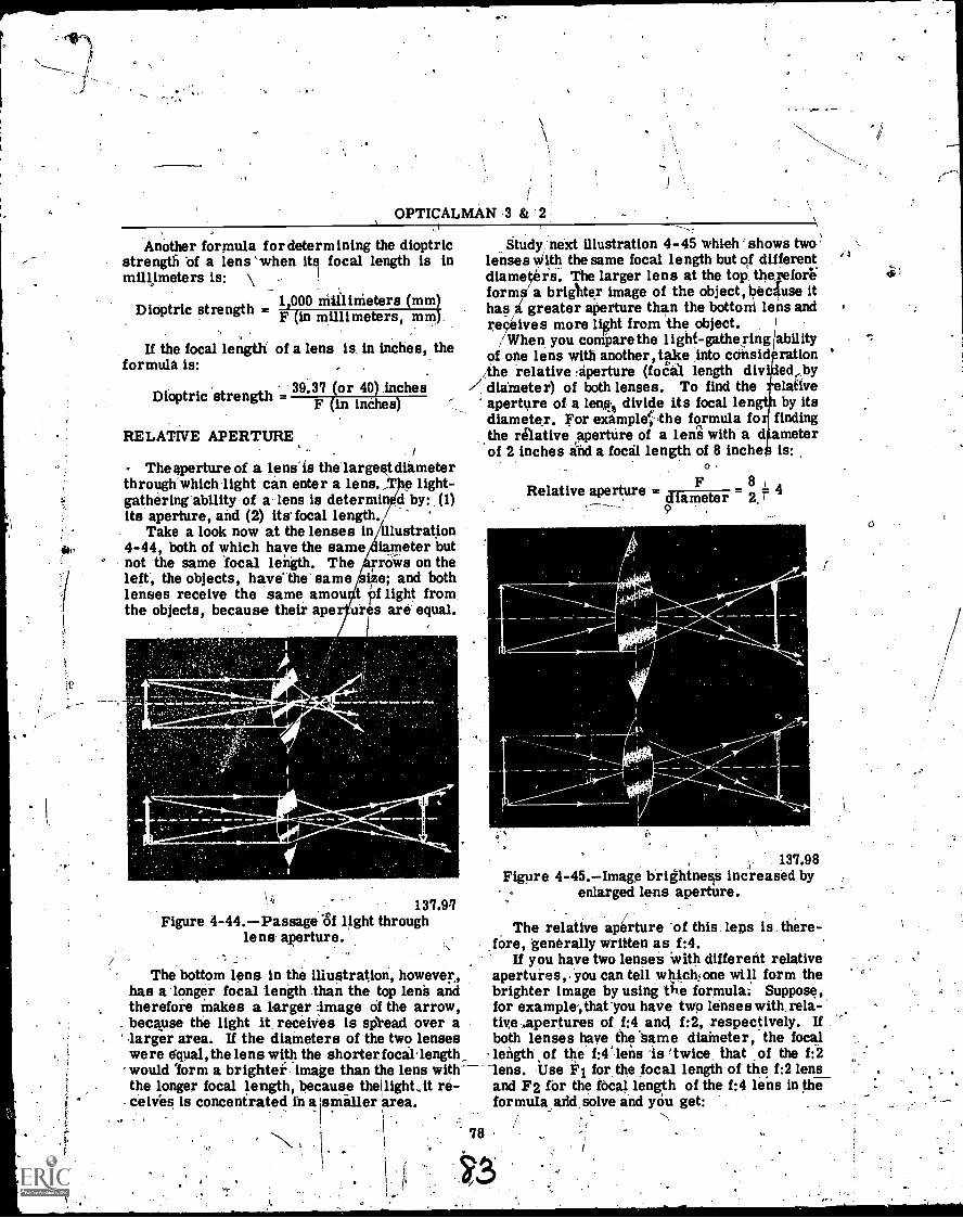
OPTICALMAN .3 & '2
Another formula for determining the dioptricstrength of a lens `when its focal length is inmillimeters is: \ -
1,000 nitllinieters (mm)Dioptric strength - F (in millimeters, mm).
If the focal length of a lens is, in inches, theformula is:
Dioptric strength = 39.37 (or 40) InchesF (in inches)
RELATIVE APERTURE ,
. /
The aperture of a lens- is the largest dthmeterthrough whichlight can enter a lens.,T e light-gathering-ability of a. lens is determin d by: (1)its aperture, and (2) itafocal length. _
Take a look now at the lenses in illustration4-44, both of which have the same iameter butnot the same local length. The rriiiis on theleft, the objects, have' the same iie; and bothlenses receive the same amou t t f light from,the objects, because their ape ur s. are equal.
L
4111. .1.44s
_...modill101-7.."1-1110 Isow-
11,137.9
Figure 4-44.-Passage of light throughlens aperture.
. -
Study next illustration 4-45 'which- shows twolenses With the same focal length but of differentdiametkrs. The larger lens at the top, thereforformaa brighter image of the object, because ithas a greater aperture than the bottom le' s andreceives more light from the object.
/When you compare the light-gathering/abilityof one lens with another, take into ccinsid rationthe relative aperture (foal length div ed,by
/ diameter) of both lenses. To find the elativeaperture of a lent3 divide its focal 1engt by itsdiameter. For example' 'the formula forf findingthe relative aperture of a lens with a d ameterof 2 inches and a focal length of 8 inche is:
0
F8 4Relative aperture = diameter 2. r
I
ti
1.
137.98Figure 4-45.-Image brightne0 increased by
enlarged lens aperture.
The relative aperture of this. lens is. there--, fOre, generally written as f:4.
If you have two lenses with different relativeapertures,. you can tell ,whickone will form thebrighter image by using the formula: Suppose,for example,that -you have two lenses with. rela-five Apertures of f:4 and f:2, respectively. Ifboth lenses have the *Same diameter, the focallength of the f:4'.1ens is (twice that of the f:2
lens. Use F1 for the focal length of the. f:2 lens'and F2 for the focal length of the f:4 lens in theformula arkl.solve and you get:
78
The bottom lens in the illustration, however,has a longer focal length than the top lens andtherefore makes a larger image of the arrow,because the light it, receives is spread over a
'larger area. If the diameters of the two lenseswere equal, the lens with the shorter focallength,would 'form a brighter, image than the lens withthe longer focal length, because thelightit re-
, ceives is concentrated in a amiller area.
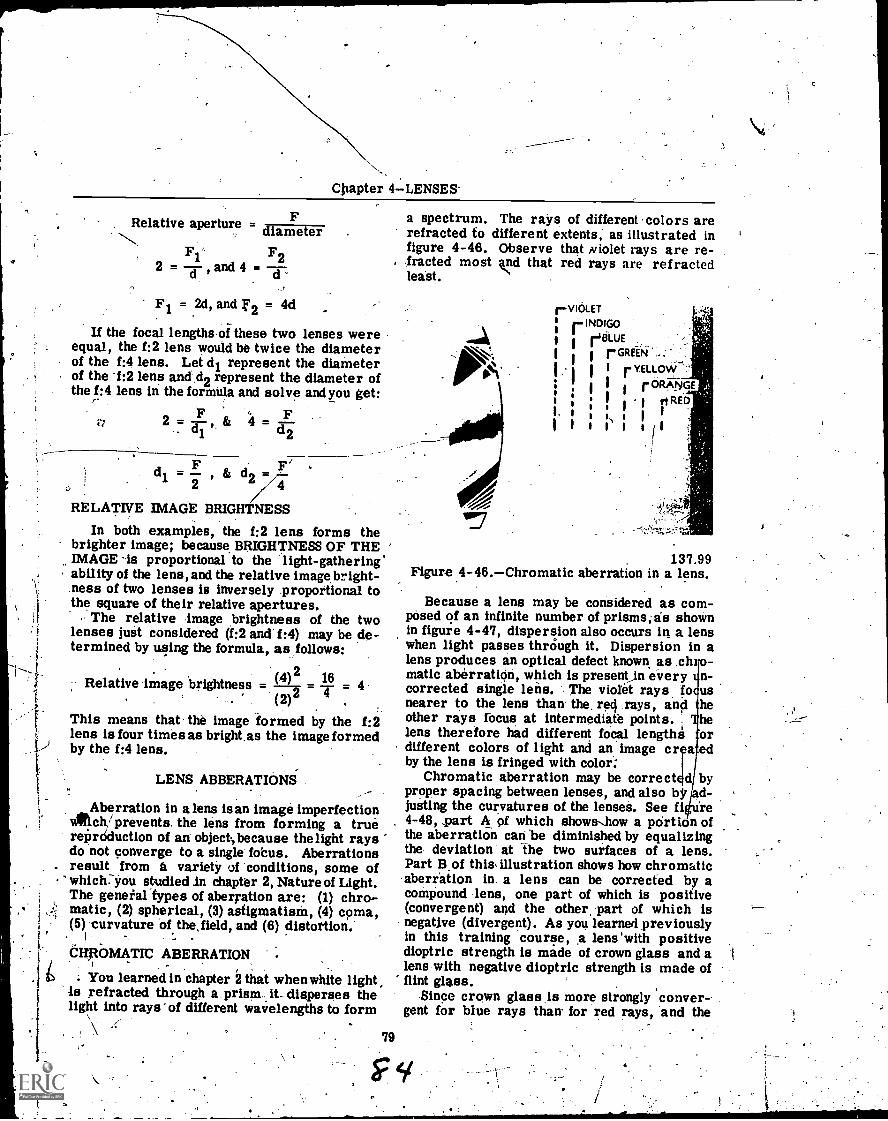
Cliapter 4-LLENSES.
Relative aperture = thanTit67F
Fi' F2and 4 =
= 2d, and f2 = 4d
If the focal lengths of these two lenses wereequal, the f:2 lens would be twice the diameterof the f:4 lens. Let d1 represent the diameterof the 1:2 lens and d2 represent the diameter ofthe f:4 lens in the formula and solve and you get:
an
= a.; =F
d1 d2
d & d1 = , d2 =2 4
RELATIVE IMAGE BRIGHTNESS
In both examples, the f:2 lens forms thebrighter image; because BRIGHTNESS OF THE
a spectrum. The rays of different colors arerefracted to different extents, as illustrated infigure 4-46. Observe that ,violet rays are re-
, iracted most and that red rays are refractedleast.
IMAGE -is proportional to the light-gatheringability of the lens, and the relative image bright-ness of two lenses is inversely proportional tothe square of their relative apertures.
The relative image brightness of the twolenses just considered (f :2 and f:4) may be de-termined by using the formula, as follows:
(4)2 16Relative image-brightness = - T = 4(2)2
This means that the image formed by the f:2lens is four times as bright,as the image formed
I ) by the f:4 lens.
LENS ABBERATIONS
...Aberration in a lens is an image imperfection1A/rich/prevents the lens from forming a truerePrdduction of an object,because thelight raysdo not converge to a single fobus. Aberrations
. result from a variety of conditions, some ofwhich.-you studied In chapter 2, Nature of Light.The geneial types of aberration are (1) chro-matic, (2) spherical, (3) astigmatism, (4) coma,(5) curvature of the, field, and (6) distortion.
CHTtOMAT/C ABERRATION
; You learned in chapter 2 that when white lightis refracted through a. prism it.. disperses thelight into rays-of different wavelengths to form
79
rEiLUE
I
1
r:
1,111 roctekNGE, '$RED
i
137.99Figure 4-46.Chromatic aberration in a lens.
Because a lens may be considered as com-posed of an infinite number of prisms, as shownin figure 4-47, dispersion also occurs in a lenswhen light passes through it. Dispersion in alens produces an optical defect known as chro-matic aberratiOn, which is present)n every n-corrected single lens. The violet rays fo usnearer to the lens than the. red rays, and heother rays fbcus at intermediate points. helens therefore had different focal lengthA ordifferent colors of light and an image cr a edby the lens is fringed with color;
Chromatic aberration may be correct d byproper spacing between lenses, and also bk ad-justing the curvatures of the lenses. See fi "re4-48, part A of which shows.how a pOrtion ofthe aberration can be diminished by equalizingthe deviation at the two surfaces of a lens.Part B of this, illustration shows how chromaticaberration in a lens can be corrected by acompound lens, one part of which is positive(convergent) and the other, part of which isnegative (divergent). As you learned previouslyin this training course, a lens 'with positivedioptric strength is made of crown glass and alens with negative dioptric strength is made offlint glass.
Since crown glass is more strongly conver-gent for blue rays than for red rays, and the
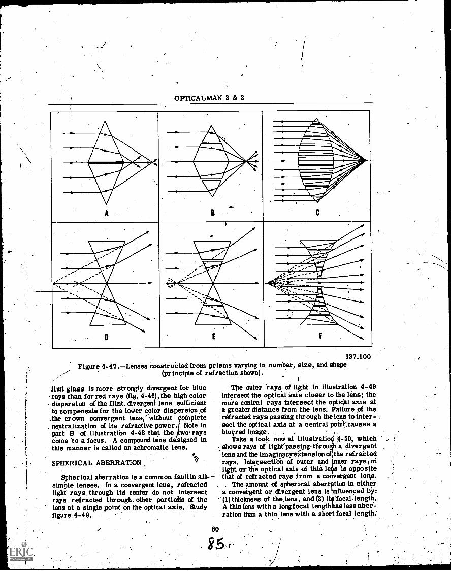
OPTICALMAN 3 & 2
AM
AMIL4.111141111kIli.-.
11110.Vir
.0,
B
', ......./, , .
.
C. .
.
.1111.67.--
- wiwat
/11110Pzir.Wm"idirti ,
... ... lir ... I' ...4,:`=°:.: --- i
. A4.
----i
.1114,
. itilk . .. Nal.
Mak gala5,Anara...
AIM' ilatt.
D F .
137.100Figure 4-47.Lenses constructed from prisms varying in number, size, and shape
(principle of refraction 'shown).(
flint glass is more strongly divergent for blue The outer rays of light in illustration 4-49rays than for red rays (fig. 4-46), the high color intersect the optical axis closer to the lens; thedispersion of the flint_ divergent lens sufficient more central rays intersect the optNal axis atto compensate for the lower color dispersion of a greater distance from the lens. Failure'of thethe crown convergent lens; without complete refracted rays passing through the lens to inter-
, neutralization of its refractive power. NoteNote in sect the optical axis at a central poik.causes apart B of illustratibn 4-48 that the o. rays blurred image. .
come to a focus. A compound lens designed in Take a look now at illustratiori 4-50, whichthis manner is called an achromatic lens. shows rays of lighepassing-through a divergent
. lens and the imaginaryeitension oft the refrabtedSPHERICAL ABERRATION 'kf rays. Intersection of outer and inner rays \ of
, light.corthe optical axis of thii 10s is oppositeSpherical aberration is a common fault in all-- that of refracted rays from a co vergent Loris.
simple lenses. In a convergent lens, refracted . . The amount of spherical aberr ion in eitherlight' rays, through ith center do .not intersect a convergent or divergent lens is luenced by:rays refracted through. other portiofts of the (1) thickness of thslens, and (2) i .focal. length.lens at a single point on the optical axis. Study A' thin lens with a longfocal length has less aber-figure 4-49. . ration than a thin, lens with a short focal length.
80,

Chapter 4LENSES
ANGLE 2
=ANGLE 1 ANGLE 2
ANGLE I
FOR LEAST CHROMATICABERRATION
CROWN GLASS
RED
VIOLET
FLINT GLASS
A. Correction for least chromatic aberrationby curvature of the lens.
B. Correction for chromatic aberration by a137.101
Fiiure 4-48.Correction of chromaticaberration in a fens.
One method of reducing spherical aberration,at the expense, of light intensity, is to test a lensto find out how much of the area around theoptical axis (where the lens is most free of.aberration) may be used to form a sharp image,and then to mask out with afield stop all rayswhich pass through the lens beyond this circle.Study illustration 4-51.
Observe in figure ;4-51 the rays blocked bythe field stop from passage through the lens.This field step is aflat ring or diaphragm madeof metal (or other suitable opaque material) tomask the outer portion of the lens. The stop pre-vents rays from striking the lens and thus re-duces the amount of light which passes through it.
11111111F
I
137.102Figure -49.Spherical aberration in a
convergent lens.
..4C4Y1,41..niiiiMagild.afti4SWM7.777J111D
040," 137.103Figure 4 -50. Spherical aberration in a
diverge& lens.
Spherical aberration in a lens can be mini-mized also by. BENDING THE LENS, which canbe accomplished by increasing the curvature ofone surface and decreasing the curvature of theother 'surface. This process retains the samefocal length of the lens but reduces the amountof aberration.
In tellescopes, spherical aberration is reducedby placing the greater curvature of each lenstoward the parallel rays to make the deviationof the rays at each surface nearly equal. In orderto reduce the amount of spherical aberration to
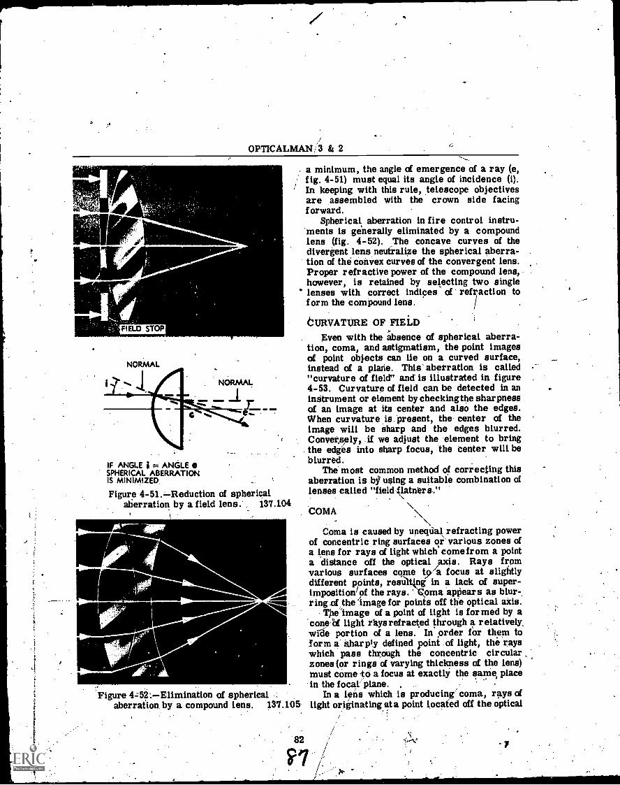
OPTICALMA/4,3 & 2
t
FIELD STOP
NORMAL
a minimum, the angle of emergence of a ray (e,fig. 4-51) must equal its angle of incidence (i).In keeping with this rule, telescope objectivesare assembled with the crown side facingforward.
Spherical aberration in fire control instru-ments is generally eliminated by a compoundlens (fig. 4-52). The concave curves of thedivergent lens neutralize the spherical aberra-tion of the convex curves of the convergent lens.Proper refractive power of the compound lens,however, is retained by selecting two singlelenses with correct indices of ref
factionto
form the compound lens.
CURVATURE OF FIELDEven with the absence of spherical aberra-
tion, coma, and astigmatism, the point imagesof point objects can lie on a curved surface,instead of a plane. This aberration is called"curvature of field" and is illustrated in figure4-53. Curvature of field can be detected in aninstrument or element by checking the sharpnessof an image at its center and also the edges.When curvature is Present, the center of theimage will be sharp and the edges blurred.Conversely, if we adjust the element to bringthe edges into sharp focus, the center will beblurred.
The most common method of correcting thisaberration is bg using a suitable combination oflenses called "field flatners."
\COMA
Coma is caused by unequal refracting powerof concentric ring surfaces or'various zones ofa lens for rays of light which come from a pointa distance off the optical Axis. Rays fromvarious surfaces come tya focus at slightlydifferent points, resti1t1 in a lack of super-imposition/of the rays. oma appears as blur-ring_ofthe image for points off tile optical axis.
The 'image of a point of light is formed by aconed light rays refracted through a relatively,wide portion of a lens. In ,order for them toform a' Sharply defined point of light, the rayswhich pass throUgh the concentric circularzones (or rings of varying thickness of the lens)Must come to a focus at exactly the same, place-. in the focal plane.
Figure 452:Elimination of spherical . In a lens which is producing' coma, rays ofaberration, by a compound lens. 137.105 light originating at a point located off the optical
. .
NORMAL
1D
C
IF ANGLE i = ANGLE 0SPHERICAL ABERRATIONIS MINIMIZED.
Figure 4-51.Reduction of sphericalaberration by a field lens. 137.104
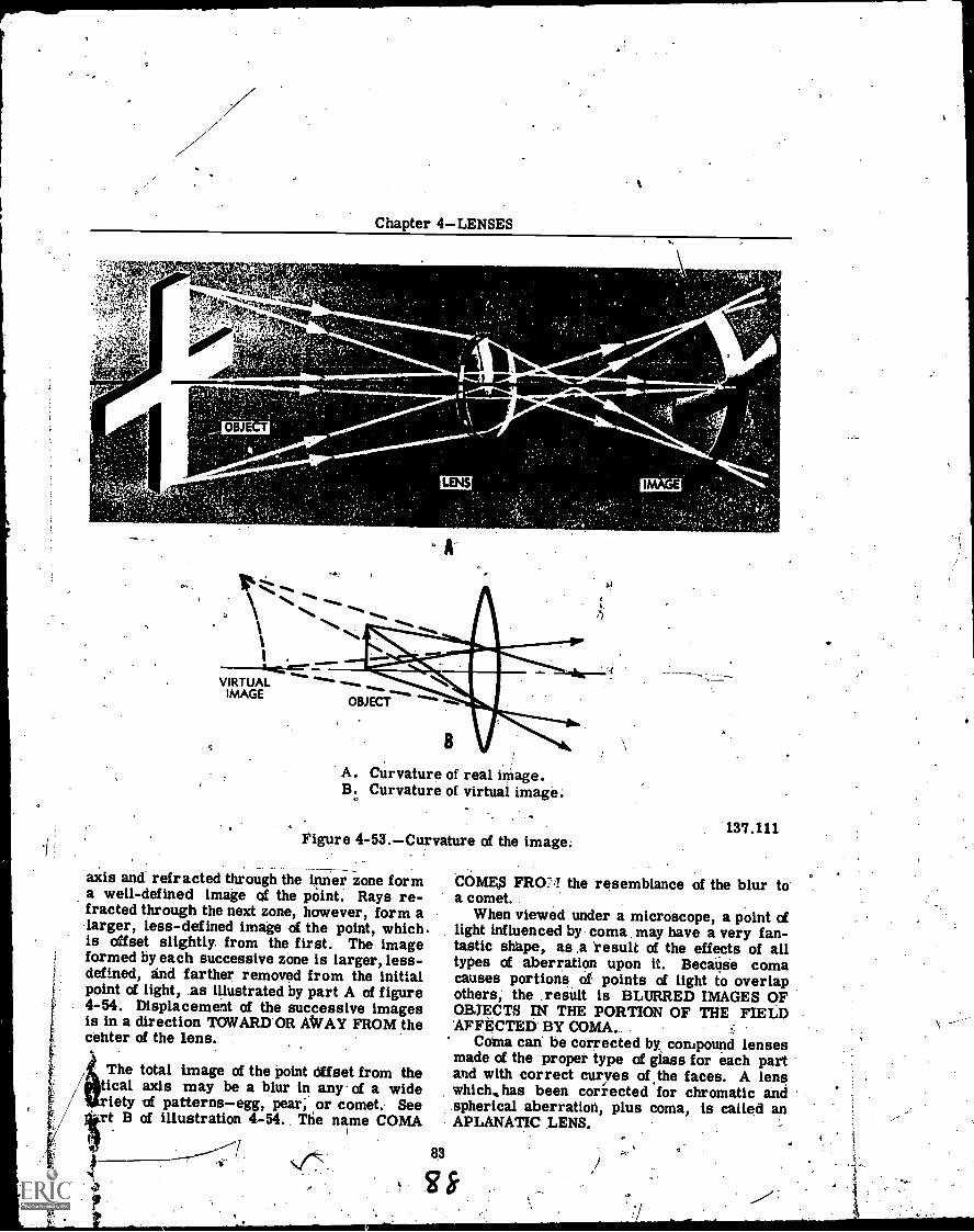
e
Chapter 4LENSES
v,1".14.1e44024ffratiar---
" .
OBJ
"*"'%.
.4%.
VIRTUALIMAGE
OBJECT
LENS
A
A. Curvature of real image.B. Curvature of virtual image:
Figure 4-53.Curvature of the image._
axis and refracted through the inner zone forma well-defined image of the point. Rays re-fracted through the next zone, however, form alarger, less-defined image of the point, whichis offset slightly from the first. The imageformed by each successive zone is larger, less-defined, and farther removed from the initial
1 point of light, as illustrated by part A of figure4-54. Displacement of the successive imagesis in a direction TOWARD OR AWAY FROM thecenter of the lens.
The total image of the point Offset from thetical axis may be a blur in any- of a wideiety of patternsegg, pear; or comet. See
-rt B of illustration 4-54. The name COMA
83
g
137.111
COMES FRO:',I the resemblance of the blur toa comet.
When viewed under a microscope, a point oflight influenced by coma, may have a very fan-tastic shape, as a 'result of the effects of alltypes of aberration upon it. Because comacauses portions of points of light to overlapothers, the ,result is BLURRED IMAGES OFOBJECTS IN THE PORTION OF THE FIELD'AFFECTED BY COMA.
Coma can be corrected by, compound lensesmade of the proper type of glass for each partand with correct curves of the faces. A lenswhich, has been corrected for chromatic and.spherical aberration, plus coma, is called anAPLANATIC LENS.
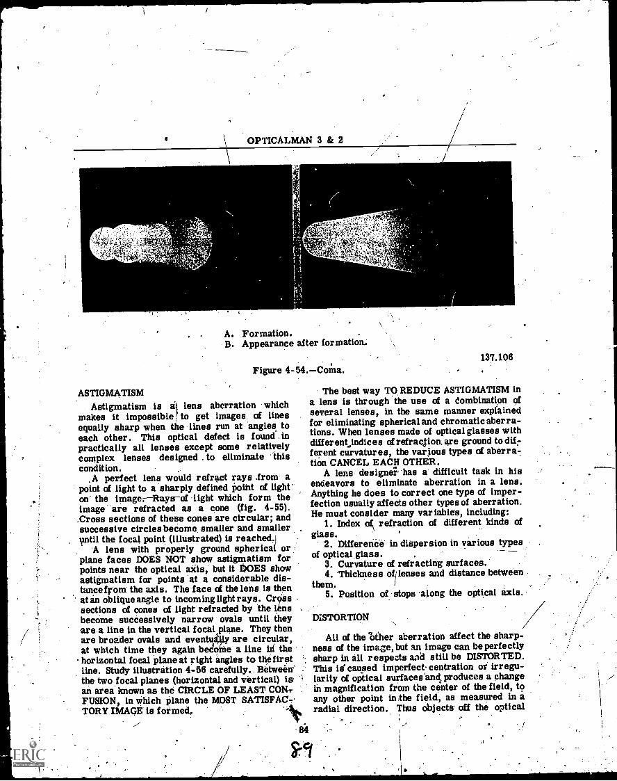
OPTICALMAN 3 & 2
r t S
lad.0,
A. Formation.B. Appearance after formation.
137.106Figure 4 -54. Coma.
The best way TO. REDUCE ASTIGMATISM ina lens is through the use of a Combination ofseveral lenses, in the same manner expfainedfor eliminating spherical and chromatic aberra-tions. When lenses made of optical glasses withdifferent indices of refraction. are ground to dif-ferent curvatures, the various types of aberra-,tion CANCEL EACH OTHER.
A lens designe; has a difficult task in hisendeavors to eliminate aberration in a lens.Anything he does to correct one type of imper-fection usually affects other types of aberration.He must consider many variables, including:
1. Index of refraction of different kinds ofglass.
2. Differena in dispersion in various typesof optical glass.
3. Curvature of refracting surfaces.4. Thickness ofilenses and distance between
them.5. Position of stops 'along the optical axis.
ASTIGMATISMAstigmatism is a lens aberration which
makes it impossible to get images of linesequally sharp when the lines run at angles, toeach other. This optical defect is found. inpractically all lenses except some relativelycomplex lenses designed . to eliminate thiscondition.
,A perfect lens would refract rays .from apoint of light to a sharply defined point of light'on the image: Rays of light which form theimage are refracted as a cone (fig. 4-55)..Cross sections of these cones are circular; andsuccessive circles become smaller and smallerwail the focal point (illustrated) is reached.i
A lens with properly ground spherical orplane faces DOES NOT show astigmatism forpoints near the optical ails, but it DOES showastigmatism for points at a considerable dis-tancefrom the axis. The face of the lens is thenMin oblique angle to incoming light rays. ClIsssections of cones of light refracted by the 1 nsbecome successively narrow ovals until they.are .a line in the vertical focal plane. They thenare broader ovals and eventu4ly are circular,at which time they again bedoine a line in thehorizontal focal plane at right angles to the firstline. Study illustration 4-56 carefully. Between'the two focal planes (horizontal and vertical) isan area known as the CIRCLE OF LEAST CON?FUSION, in which plane the MOST SATISFAC-.TORY IMAGE is formed,
84
DISTORTION
All of the 'Other aberration affect the sharp-ness of the image, but an image can be perfectlysharp in all respects and still be DISTORTED.This is caused imperfect centration or irregu-larity of optical surfaces'and, produces a changein magnification from the center of the field, toany other point in the field, as measured in aradial direction. Thus objects off the optical
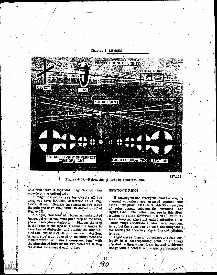
i
Chapter 4LENSES
".
4'40b1::' .!= !;.4.4 111
PERFECT CONE OF LIGHT' s
LENS
1. j
FOCAL P INT
ENLARGED VIEW OF PERFECTCONE OF IGHT
...,,;.',FOCAL POINTIi
)1elftik.w.x
CIRCLES SHOW CROSS SECTION
Figure 4-55.Refraction of light by a perfect lens.
axis will have a diferent magnification thanobjects on the optica axis. .
If magnification i less for objects off theaxis, you have AR 1L distortion (A of Fig.4-57). If magnificatih increases ias you leavethe axis you have P /CUSHION distortion (C ofFiis. 4-57).
A single, thin lens will form an undistortedimage,but when you must put a stop on the axis,you will introduce distortion; Placing the stopin the front of the lens will cause the image tohave barrel distortion and placing the stop be-hind the lens will cause pin cushion distortion.When a stop' must be used in an instrument themanufacturer will use a compound lens" withthe stop placed between the two elements, lettingthe 'distortions cancel each other.
NEWTON'S RINGS .
# 5
137.107
If convergent and divergent lenses of slightlyunequal curvature are pressed against eachother, irregular COLORED BANDS or patchesof color appear between the surfaces. Seefigure 4-58. The pattern you see in this illus-
. tration is called NEWTON'S RINGS, after SirIsaac Newton, who first called attention to it.These rings constitute a defect in a compoundlens; but the rings can be used advantageouslyfor testing the accuracy of grinding and polishinglenses.
Light waves from an object never focus per-nt a corresponding point on an image
rated by themthey form instead a diffusedimage with a central white spot .surroiMded by
t
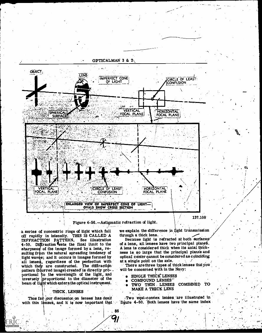
r
OPTICALMAN 3 &
OBJECTLEN$:
:IMPERFECTCC:AilOF LIGHT
CIRCLE OF LEASTCONFUSION
CIRCLE OF LEAST ;. HZ) ITAT.CONFUSION . FOCAL PLANE
ENLARGED VIEW OF IMPERFECT CONE OF LIGHT =1OVALS SHOW CROSS SECTION
Figure 4-56.Astigmatic refraction of light.
a series of concentric rings of light which fall we explain the difference in 1off rapidly in intensity. THIS IS CALLED 'A through a thick lens. .
DIFFRACTION PATTERN. See illuistration.4 -59.-sharpnessuiting frlight wayall Tensewhich thpattern (bportionalinverselybeam of li
Thus fwith thin I
raction sets the final limit to theof the image formed by a lens,, re-m the natural spreading tendency ofs; and it occurs in images formed by, regardless of the perfection with
are constructed. The diffractiOnurred image) created' is directly prb- .o the wavelength of the light, andproportional to the diameter of theht which enter sthe optical instrument.
THICK LENSES
-hour discussion on lenses- has dealtnses, and it is now important, that '-
1
, 86
137.108
*ght transmission
Because light is refracted at both surfaceof a lens, all lenses have two principal planA lens is considered thick when its axial thick-ness is so large that the principal planE(s andoptical center cannot be considered as coincidingat a single point on the axis. /
There are three types, of thick lenses that you.will-be concerned with in the Navy:
SINGLE THICK'. LENSES-COMPOUND LENSES**. iwcy THIN , LENSES COMBINED TOMAKE' A THICK LENS .
Two 'equi-convex lenses are illustrated in'figure 4-60. Both lenses have the same index
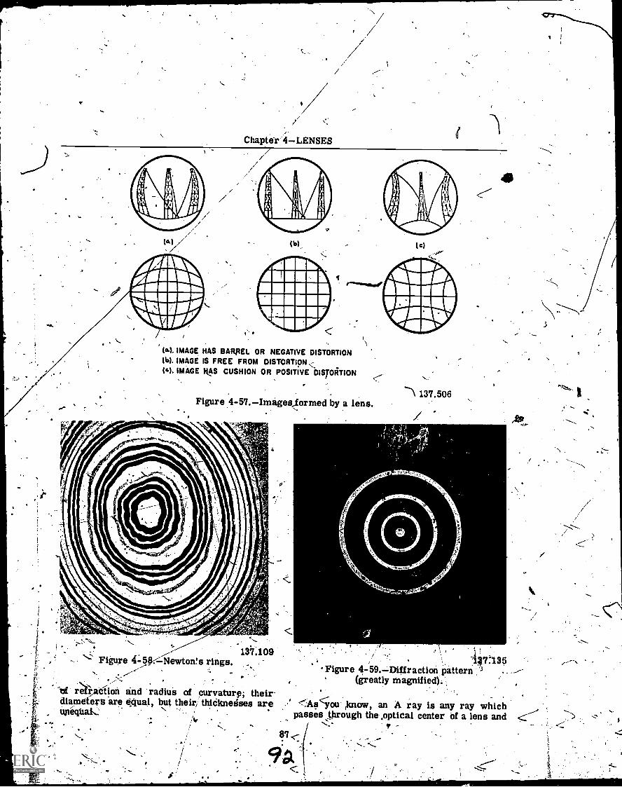
Chapter 4LENSES
(b),
lo). IMAGE HAS BARIIEL OR NEGATIVE DISTORTION(W. IMAGE IS FREE FROM DISTORTION(O. IMAGE HAS CUSHION OR POSITIVE DISTORTION
Figure 4-57.Imagekformed by a lens.
, .:. . - ..137.109 ,' -- ;
47:135'-' Figure 45.8.-..-:-Newton!s'
rings. ..-- Figure 4-59.Erlffraction pattern ''''l .. ---
(greatly magnified). , ,
As ou ,know, an A ray is any ray whichpasses through the ,optical center Of a lens and..
37
K
-1137.506
iS'
a...
2N., W01,,,..._,..,.. ..
,..
fr
.
"'of refraction and radius of curvature; theirdiameters are equal, but their, thiCknedses are
9a
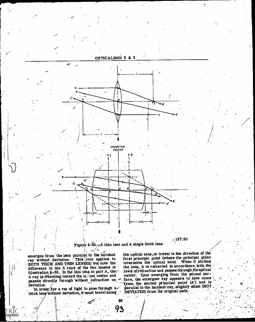
OPTICALMAN 3 & 2
60
V
A
GEOMETRICCENTER
p1
B
Figure 4-60.7A thin lens and.a single thick lens.1
emerges from the lens parallel to the incident . the optical axis, or travel in the direction of the
ray without deviation. This rule applies to first principal point (where the principal plane
iBOTH THICK AND THIN LENEESrbut note the : intersects the optical axis).. When it strikes -.
,.t difference in the A-rays of the two lenses in the lens it is refracted in accordance/with the .
illustration 60. In the thin lets in part A; the I- laws otiefraction and passes through he-optical' .-
A ray is t1veling toward the ov lcal center and center. Upon emerging from th Øcond sur-
passes direc y thiough 'without refraction or- z- face, the emergent ray appears to have come
deviation. from_ the second principal. point' -(At) and is , if,
_ In order for a ray of light to pass through ae parallel. to the-Incident ray, slightlir offset (NOT. , ,.. ..
thick len without deviation, it 4must travel along. DEVIATED) from iti3. original-path. . ..
_.
93 /
A 137.90
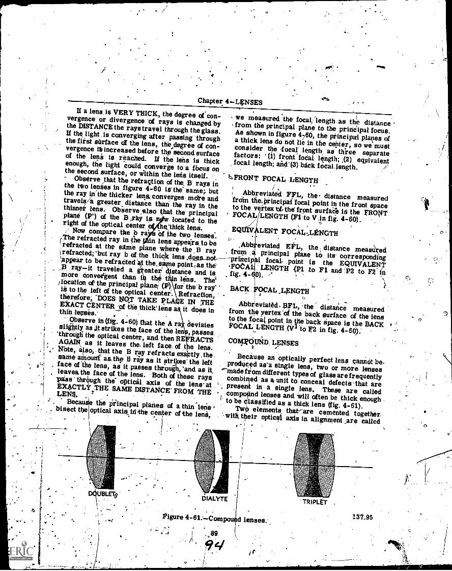
O
Chapter 4LENSESIf a lens. is VERY THICK, the degree of con-vergence or divergence of rays is changed by
the DISTANCE the rays travel through the glass.If the light .18 converging after passing 'throughthe first surface at the lens, the degree of con-vergence ii3 increased before the second surfaceof the lens is reached. If the lehs is thickenough, the light could converge to a focus onthe second surface, or within the lens itself.Observe /that the refraction of the B rays inthe two lenses in figure 4-60 113-the' same;. butthe ray in the thicker leqs.'converges- more andtravels/a greater distance than the ray in thethinner lens. Observe ,also that the principalplane (P') of the B jay is nyw located to theright of the optical center. *fhe'thick lens./' Now compare the b rap Of the two lenses'.The refracted ray in sthe in lens appears to berefracted at the same plane where the B ray
`appear
but ray b of the thic lens sit-0..s_not\appear to be refraCtedt the.same pointas the'.13 rayit traveled a eater stance and is.
1\More convergent than i the n lens. The'ilOcation of the principal Plane, (P) for' the b ray'ii to the left of the optical center. Refractiontherefore -DOES NOT TAKE PLAQE IN THEEXACT CENTER...pf the thick' lens a it does inthin lenses.' , .
,'.Observe in (fig. 4-60) that the A ra deviatesslightly as At strikes the face of the len , passes.'through the optical center, and then RE RACTSAGAIN as it leaves the- left face, of t e lens.NOW, also, that the B ray refracts e tly .thesame anloun as. the 6 ray as it strikes' the leftface othe lens, as it passes throuih, 'and as itleaves, the face of the tette. Both of these rays-piss' thrOugh the- optical, axis of the lens at .EX4CTLY THE SAME DISTANCE' FROM THE°LENS.Becau e the Principal planes of a thin'iens. bisect the optical axis..hi-the center of the lens,
I
we measured the focal/ length as the distancefrom the principal plane to the prinCipal focus.As shown in figure 460, the principal planes ofa thick lens do not lie in the ceiter, so we mustconsider the 'focal length as three separatefactors: ' (i) front 'fodal length; ,(2) equivalentfocal length; and(3) back focaLlength.
,.FRONT FOCAL LENGTH
Abbreviated FFL, the- distance measuredroin the.Principai focal point in the front spaceto the v rtex 'of. the front surface is the FRONTFOCAL LENGTH (Filo V in fig. 4-60).
,
EQ LENT FOCAL ,LENGTH
.Abb eviated EFL, the distance meastiredfrom principal plan to its- corresponding--principhl focal. .point is the EQUIVALENT-FOCAL LENGTH .(131 to Fl and 'P2 to F2 infig. 4-60). .
r./
BACK FOCALt,
Abbreviated, BFL, the distance measuredfrom the vertex -of-the back surface of the lensto the focal point in the back apace is the BACK'FOCAL. LENGTH (Vi to F2 in fig. 4-60):.COMR6UND, LENSES
b' o'
Because an optically perfect lens cannot be.produced as'a single lens, two or more lensesfitom different types of glass are frequentlycombined as a unit to. conceal defects that arepresent in a single lens. These are calledcomprd lenses and often be thick enoughto be lassffied as a thick lens (fig. 4-61).Two eleinents thatare cemented together.with Urir optical axis in alignment are called
D UBLET0'DIALYTE
is
137,95Figure 4-61:Compo
0.
r 89
d lenses.
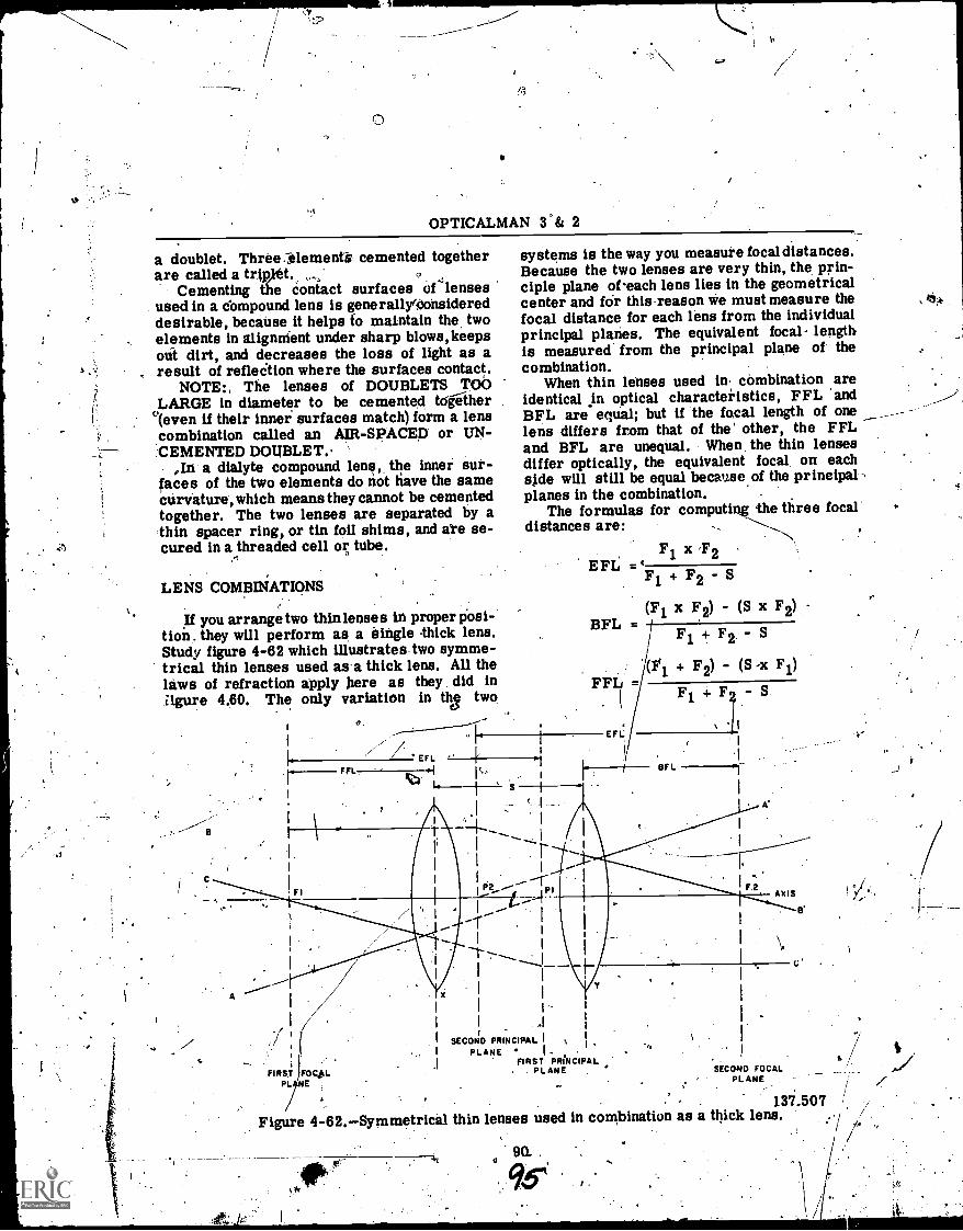
OPTICALMAN 3°& 2
a doublet. Three.ilemena, cemented togetherare called a trir 0t.
Cementing e contact surfaces of lensesused in a compound lens is generallyOonsidereddesirable, because it helps to maintain the, twoelements in alignMent under sharp blows,keepsout dirt, and decreases the loss of light as aresult of refleition where the surfaces contact.
NOTE:, The lenses of DOUBLETS TOOLARGE in diameter to be cemented toither°(even if their inner surfaces match) form a lenscombination called an AIR- SPACED or UN-:CEMENTED DOUBLET.
,In a dialyte compound lens, the inner sur-faces of the two elements do not have the samecurvature, which means they cannot be cementedtogether. The two lenses are separated by athin spacer ring, or tin foil shims, and ate se-cured in a threaded cell or tribe.
LENS COMBINATIONS
If you arrange two thinlenses in proper pOsi-tion. they will perform as a single thick lens.Study figure 4-62 which illustrates two symme-trical thin lenses used as'a thick lens. All thelaws of refraction apply here as they did inigure 4.60. The only variation in qv two
o.
FFL,EFL
systems is the way you measure focal distances.Because the two lenses are very thin, the prin-ciple plane of-each lens lies in the geometricalcenter and for thisreason we must measure thefocal distance for each lens from the individualprincipal planes. The equivalent focal lengthis measured from the principal plane of thecombination,
When thin lenses used in combination areidentical in optical characteristics, FFL. andBFL are equal; but if the focal length of onelens differs from that of the other, the FFLand BFL are unequal. When the thin lensesdiffer optically, the equivalent focal on eachside will still be equal because of the principal-,planes in the combination. .
The formulas for computing the three focal'distances are:
F 1 x ,F 2EFL
=`F1F1 + F2 -S
BFL =
EFL
(Fi x F2) - (S x F2)
Fl t F2 S
(Fi + F2) - (S -x F1)
BFL
Fi + S
'1
AXIS
I.
/4//
FIRST FOCAL
,
1
SECOND PRINCIPALPLANE I
FIRST PRINCIPAL. . PLANE SECOND FOCAL
PLANE
137.507Figure 4-62.Symmetrical thin lenses used in combination as a thick lens. .
90-,
9T' I

Chapter 4LENSESF1 = focal length of lens A (in combination)
F2 = focal length of lens B (in combination)
S = separation of the two lenses (X & Y, orleft and right) in a combination, meas-ured from their principal planes.
Refer now to figure 4-63 which illustrates theuse of two thin lenses in combination whenmaking an eyepiece of a telescope. You willstudy eyepiece systems in detail in chapter 5,but the application is very appropriate at thispoint.
AXIS
lens is necessary at the point where a reticleis generally mounted and the markings aretherefore engraved on it. The function of areticle is to SUPERIMPOSE reference markson the view of a target.
Colored Filters
Filters (sometimes called ray filters) arecolored glass disks (with plane parallel sur-faces) placed in the line of sight in optical in-struments to reduce glare and light intensities.They are separate elements and may be attachedor detached (A & B of fig. 4-64), or they may
Figure 4-63.Two thin lenses used as an eyepiece.
As you study the illustration, you will noticethat lens X is within the focal length of lens Yand it makes the diverging rays from focalplane F2 less diverging. Also notice that thefocal length of lens Y is longer than the EFL.This helps to illustrate the fact that each thinlens in a combinationhas a definite focal length,but when used together the resulting EFL of thecombination is shorter than the Fl of either lens.
MISCELLANEOUS OPTICAL ELEMENTS
In addition to the optical elements studiedthus far there are three additional elements thathave an effect on light transmission in an instru-ment. These elements are RETICLES, COLORFILTERS, AND POLAROID FILTERS.
Reticles
Most reticles used in optical instrumentsare glass disks with plane parallel surfaces, onone of which appropriate markings are engravedor etched. In some instances, a planoconvex
91
137.508
be mounted on a rotating disc which makes in-sertion and removal from the path of light easy.Part C of figure 4-64 shows a disc with threecolored and one neutral filter mounted.
Some of the different types of colored filtersemployed in optical instruments in order to im-prove visibility under varying conditions oflight and atmosphere are amber, blue, green,red, smoke, and yellow.
Amber and red filters are generally usedunder varying conditions of fog and grolnd haze.Red filters are also employed for observingtracer fire. Amber and yellow filers protectthe eyes from reflections of sunlight on waterand glare from various sources. Blue filtersare helpful in determining when objects and/orareas camouflaged.
Greenish-yellow filters have both green andyellow colors in their composition,and they canserve the same purpose as amber and smoke.A smoke filter is a dark filter used to protectthe eyes from a bright sun or a searchlight.This type of filter is usually too dark for otherpurposes.
96
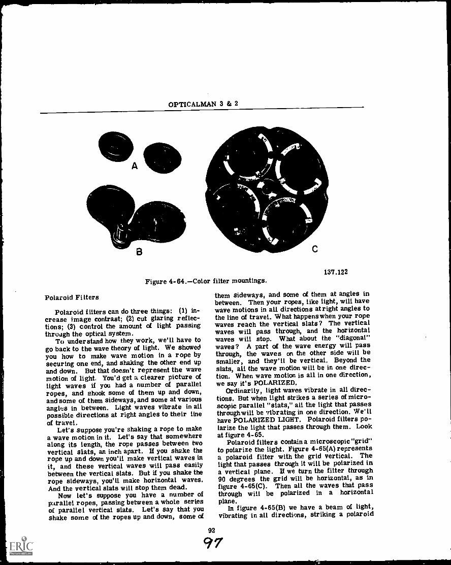
OPTICALMAN 3 & 2
A
B
Polaroid Filters
Figure 4-64.Color filter mountings.
Polaroid filters can do three things: (1) in-crease image contrast; (2) cut glaring reflec-tions; (3) control the amount of light passingthrough the optical system.
To understand how they work, we'll have togo back to the wave theory of light. We showedyou how to make wave motion in a rope bysecuring one end, and shaking the other end upand down. But that doesn't represent the wavemotion of light. You'd get a clearer picture oflight waves if you had a number of parallelropes, and shook some of them up and down,and some of them sideways, and some at variousangles in between. Light waves vibrate in allpossible directions at right angles to their lineof travel.
Let's suppose you're shaking a rope to makea wave motion in it. Let's say that somewherealong its length, the rope passes between twovertical slats, an inch apart. If you shake therope up and down you'll make vertical waves init, and these vertical waves will pass easilybetween the vertical slats. But if you shake therope sideways, you'll make horizontal waves.And the vertical slats will stop them dead.
Now let's suppose you have a number ofparallel ropes, passing between a whole seriesof parallel vertical slats. Let's say that youshake some of the ropes up and down, some of
92
C
137.122
them sideways, and some of them at angles inbetween. Then your ropes, like light, will havewave motions in all directions at right angles tothe line of travel. What happens when your ropewaves reach the vertical slats? The verticalwaves will pass through, and the horizontalwaves will stop. What about the "diagonal"waves? A part of the wave energy will passthrough, the waves on the other side will besmaller, and they'll be vertical. Beyond theslats, all the wave motion will be in one direc-tion. When wave motion is all in one direction,we say it's POLARIZED.
Ordinarily, light waves vibrate in all direc-tions. But when light strikes a series of micro-scopic parallel "slats," all the light that passesthroughwill be vibrating in one direction. We'llhave POLARIZED LIGHT. Polaroid filters po-larize the light that passes through them. Lookat figure 4-65.
Polaroid filters contain a microscopic "grid"to polarize the light. Figure 4-65(A) representsa polaroid filter with the grid vertical. Thelight that passes through it will be polarized ina vertical plane. If we turn the filter through90 degrees the grid will be horizontal, as infigure 4-65(C). Then all the waves that passthrough will be polarized in a horizontalplane.
In figure 4-65(B) we have a beam of light,vibrating in all directions, striking a polaroid
97
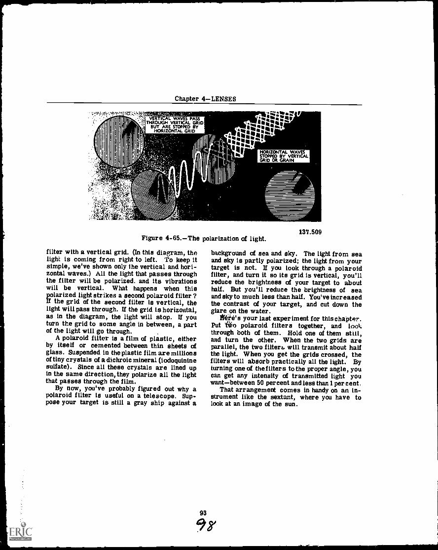
Chapter 4LENSES
-.` '6';- VERTICAL WAVES PASSTHROUGH VERTICAL GRID
BUT ARE STOPPED BYHORIZONTAL GRID
itfMtre
11,444.:Nir'
HORIZONTAL WAVESSTOPPED BY VERTICALGRID OR GRAIN
Figure 4-65.The polarization of light.
filter with a vertical grid. (In this diagram, thelight is coming from right to left. To keep itsimple, we've shown only the vertical and hori-zontal waves.) All the light that passes throughthe filter will be polarized, and its vibrationswill be vertical. What happens when thispolarized light strikes a second polaroid filter ?If the grid of the second filter is vertical, thelight will pass through. If the grid is horizontal,as in the diagram, the light will stop. If youturn the grid to some angle in between, a partof the light will go through.
A polaroid filter is a film of plastic, eitherby itself or cemented between thin sheets ofglass. Suspended in the plastic film are millionsof tiny crystals of a dichroic mineral (iodoquininesulfate). Since all these crystals are lined upin the same direction, they polarize all the lightthat passes through the film.
By now, you've probably figured out why apolaroid filter is useful on a telescope. Sup-pose your target is still a gray ship against a
93
137.509
background of sea and sky. The light from seaand sky is partly polarized; the light from yourtarget is not. If you look through a polaroidfilter, and turn it so its grid is vertical, you'llreduce the brightness of your target to abouthalf. But you'll reduce the brightness of seaand sky to much less than half. You've increasedthe contrast of your target, and cut down theglare .on the water.
}Vet's your last experiment for this chapter.Put i*o polaroid filters together, and lookthrough both of them. Hold one of them still,and turn the other. When the two grids areparallel, the two filtert, will transmit about halfthe light. When you get the grids crossed, thefilters will absorb practically all the light. Byturning one of the filters to the proper angle, youcan get any intensity of transmitted light youwantbetween 50 percent and less than 1 percent.
That arrangement comes in handy on an in-strument like the sextant, where you have tolook at an image of the sun.
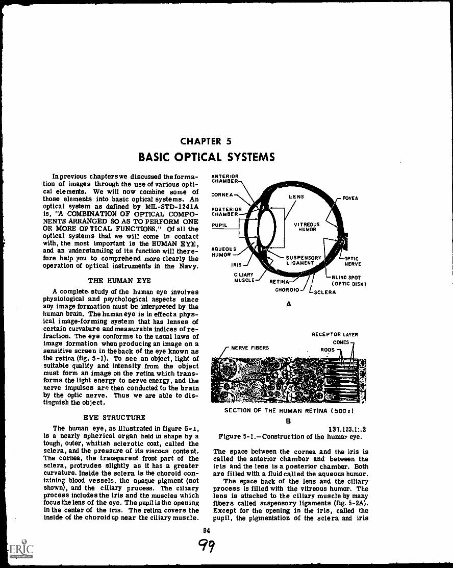
CHAPTER 5
BASIC OPTICAL SYSTEMS
In previous chapters we discussed the forma-tion of images through the use of various opti-cal elements. We will now combine some ofthose elements into basic optical systems. Anoptical system as defined by MIL-STD-1241Ais, "A COMBINATION OF OPTICAL COMPO-NENTS ARRANGED SO AS TO PERFORM ONEOR MORE OPTICAL FUNCTIONS." Of all theoptical systems that we will come in contactwith, the most important is the HUMAN EYE,and an understanding of its function will there-fore help you to comprehend more clearly theoperation of optical instruments in the Navy.
THE HUMAN EYE
A complete study of the human eye involvesphysiological and psychological aspects sinceany image formation must be interpreted by thehuman brain. The human eye is in effect a phys-ical image-forming system that has lenses ofcertain curvature and measurable indices of re-fraction. The eye conforms to the usual laws ofimage formation when producing an image on asensitive screen in the back of the eye known asthe retina (fig. 5-1). To see an object, light ofsuitable quality and intensity from the objectmust form an image on the retina which trans-forms the light energy to nerve energy, and thenerve impulses are then conducted to the brainby the optic nerve. Thus we are able to dis-tinguish the object.
EYE STRUCTUREThe human eye, as illustrated in figure 5-1,
is a nearly spherical organ held in shape by atough, outer, whitish sclerotic coat, called thesclera, and the pressure of its viscous content.The cornea, the transparent front part of thesclera, protrudes slightly as it has a greatercurvature. Inside the sclera is the choroid con-taining blood vessels, the opaque pigment (notshown), and the ciliary process. The ciliaryprocess includes the iris and the muscles whichfocus the lens of the eye. The pupil is the openingin the center of the iris. The retina covers theinside of the choroidup near the ciliary muscle.
94
ANTERIORCHAMBER
CORNEA
POSTERIORCHAMBER
PUPIL
AQUEOUSHUMOR
IRIS
CILIARYMUSCLE
NERVE FIBERS
LENS
VITREOUSHUMOR
SUSPENSORYLIGAMENT
RETINA
CHOROID
A
FOVEA
OPTICNERVE
BLIND SPOT(OPTIC DISK)
LSCLERA
RECEPTOR LAYER
CONES
RODS
SECTION OF THE HUMAN RETINA ( 500 x
B137.123.1:.2
Figure 5-1.Construction of the humar eye.
The space between the cornea and the iris iscalled the anterior chamber and between theiris and the lens is a posterior chamber. Bothare filled with a fluid called the aqueous humor.
The space back of the lens and the ciliaryprocess is filled with the vitreous humor. Thelens is attached to the ciliary muscle by manyfibers called suspensory ligaments (fig. 5-2A).Except for the opening in the iris, called thepupil, the pigmentation of the sclera and iris
49
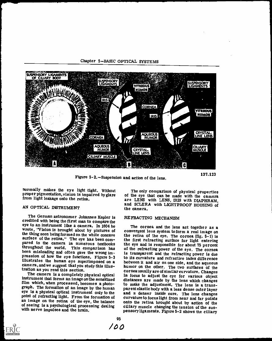
Chapter 5BASIC OPTICAL SYSTEMS
yommmer;SUSPINSORY LIGAMENTS
OF CILIARY BODY
Ili. IPzr?, 4P$41
Lt.A
r";
SUSPENSORYLIGAMENTS
IRIS
CORNEA
UAQHUMEOUSOR
CILIARY MUSCLE
VITREOUSHUMOR
CORNEA
IRIS
AQUEOUSHUMOR
SUSPENSORYLIGAMENTS
VITREOUSHUMOR
CRYSTAL-LINE LENS
CIUARYCRYSTAL-LINE LENS
MUSCLE
Figure 5-2.Suspension and action of the lens.
normally makes the eye light tight. Withoutproper pigmentation, vision is impaired by glarefrom light leakage onto the retina.
AN OPTICAL INSTRUMENT
The German astronomer Johannes Kepler iscredited with being the first man to compare theeye to an instrument like a camera. In 1604 hewrote, "Vision is brought about by pictures ofthe thing seen being formed on the white concavesurface of the retina." The eye has been com-pared to the camera in numerous textbooksthroughout the world. This comparison hasbeen misleading and often gave the wrong im-pression of how the eye functions. Figure 5-3illustrates the human eye superimposed on acamera, and we suggest that you study this illus-tration as you read this section.
The camera is a completely physical opticalinstrument that forms an image on the sensitizedfilm which, when processed, becomes a photo-graph. The formation of an image by the humaneye is a physical optical instrument only to thepoint of refracting light. From the formation ofan image on the retina of the eye, the balanceof seeing is a psychological processing dealingwith nerve impulses and the brain.
137.123
The only comparison of physical propertiesof the eye that can be made with the cameraare LENS with LENS, IRIS with DIAPHRAM,and SCLERA with LIGHTPROOF HOUSING ofthe camera.
REFRACTING MECHANISM
The cornea and the lens act together as aconvergent lens system to form a real image onthe retina of the eye. The cornea (fig. 5-1) isthe first refracting surface for light enteringthe eye and is responsible for about 75 percentof the refracting power of the eye. The corneais transparent and the refracting power is dueto its curvature and refractive index differencebetween it and air on one side, and the aqueoushumor on the other. The two surfaces of thecornea usually are of similar curvature. Changesin focus to adjust the eye for various objectdistances are made by the lens which changesto make the adjustment. The lens is a trans-parent elastic body with a less dense outer layerand a denser inside core. The lens changescurvature to focus light from near and far pointsonto the retina brought about by action of theciliary muscle changing the tension of the sus-pensory ligaments. Figure 5-2 shows the ciliary
95
/00
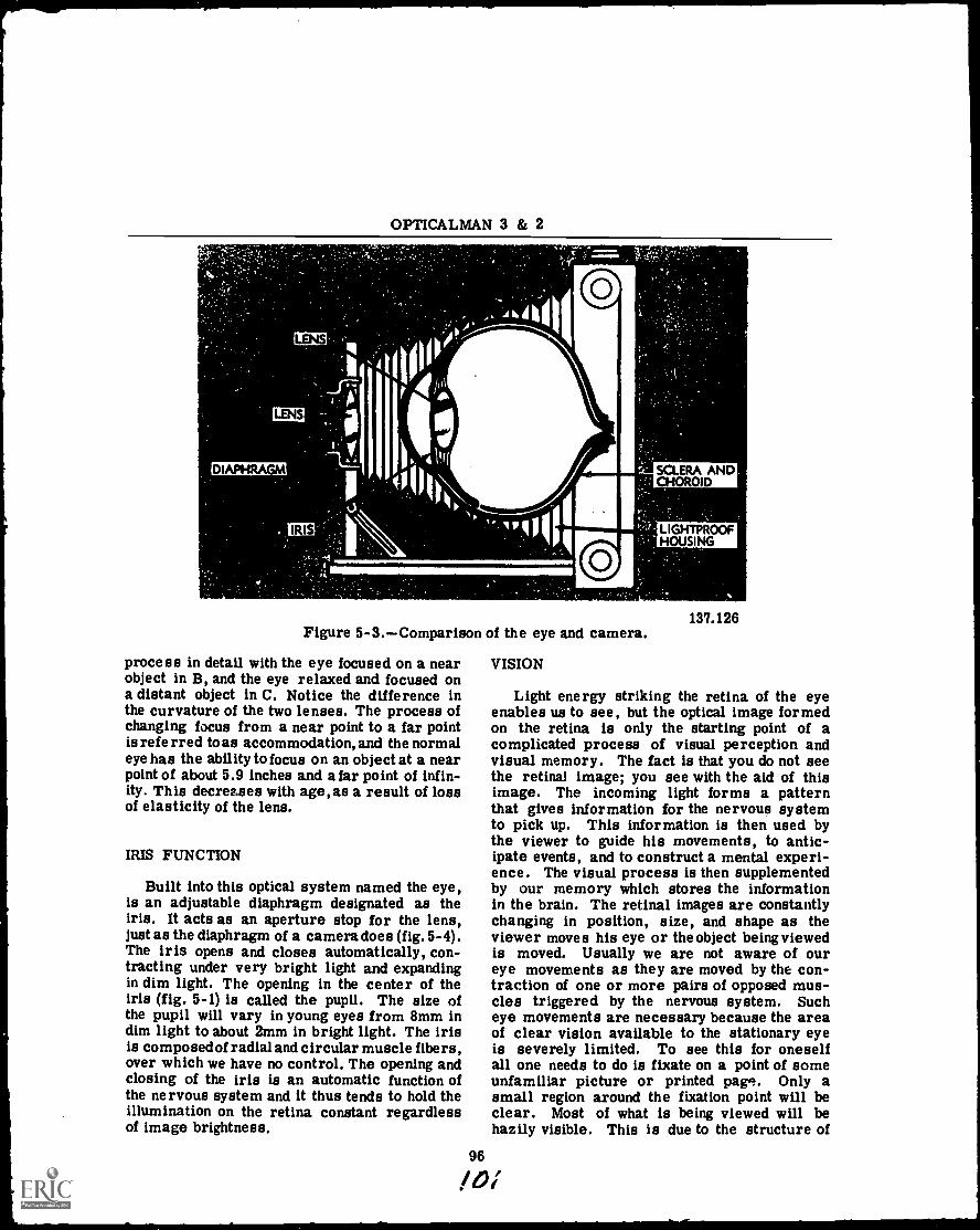
OPTICALMAN 3 & 2
LENS
LENS
DIAPHRAGM
IRIS
O
SCLERA ANDCHOROID
LIGHTPROOFHOUSING
O
137.126Figure 5-3.--Comparison of the eye and camera.
process in detail with the eye focused on a nearobject in B, and the eye relaxed and focused ona distant object in C. Notice the difference inthe curvature of the two lenses. The process ofchanging focus from a near point to a far pointis referred to as accommodation, and the normaleye has the ability to focus on an object at a nearpoint of about 5.9 inches and afar point of infin-ity. This decreases with age, as a result of lossof elasticity of the lens.
IRIS FUNCTION
Built into this optical system named the eye,is an adjustable diaphragm designated as theiris. It acts as an aperture stop for the lens,just as the diaphragm of a camera does (fig. 5-4).The iris opens and closes automatically, con-tracting under very bright light and expandingin dim light. The opening in the center of theiris (fig. 5-1) is called the pupil. The size ofthe pupil will vary in young eyes from 8mm indim light to about 2mm in bright light. The irisis composed of radial and circular muscle fibers,over which we have no control. The opening andclosing of the iris is an automatic function ofthe nervous system and it thus tends to hold theillumination on the retina constant regardlessof image brightness.
VISION
Light energy striking the retina of the eyeenables us to see, but the optical image formedon the retina is only the starting point of acomplicated process of visual perception andvisual memory. The fact is that you do not seethe retinal image; you see with the aid of thisimage. The incoming light forms a patternthat gives information for the nervous systemto pick up. This information is then used bythe viewer to guide his movements, to antic-ipate events, and to construct a mental experi-ence. The visual process is then supplementedby our memory which stores the informationin the brain. The retinal images are constantlychanging in position, size, and shape as theviewer moves his eye or theobject being viewedis moved. Usually we are not aware of oureye movements as they are moved by the con-traction of one or more pairs of opposed mus-cles triggered by the nervous system. Sucheye movements are necessary because the areaof clear vision available to the stationary eyeis severely limited. To see this for oneselfall one needs to do is fixate on a point of someunfamiliar picture or printed pap,. Only asmall region around the fixation point will beclear. Most of what is being viewed will behazily visible. This is due to the structure of
96
10%
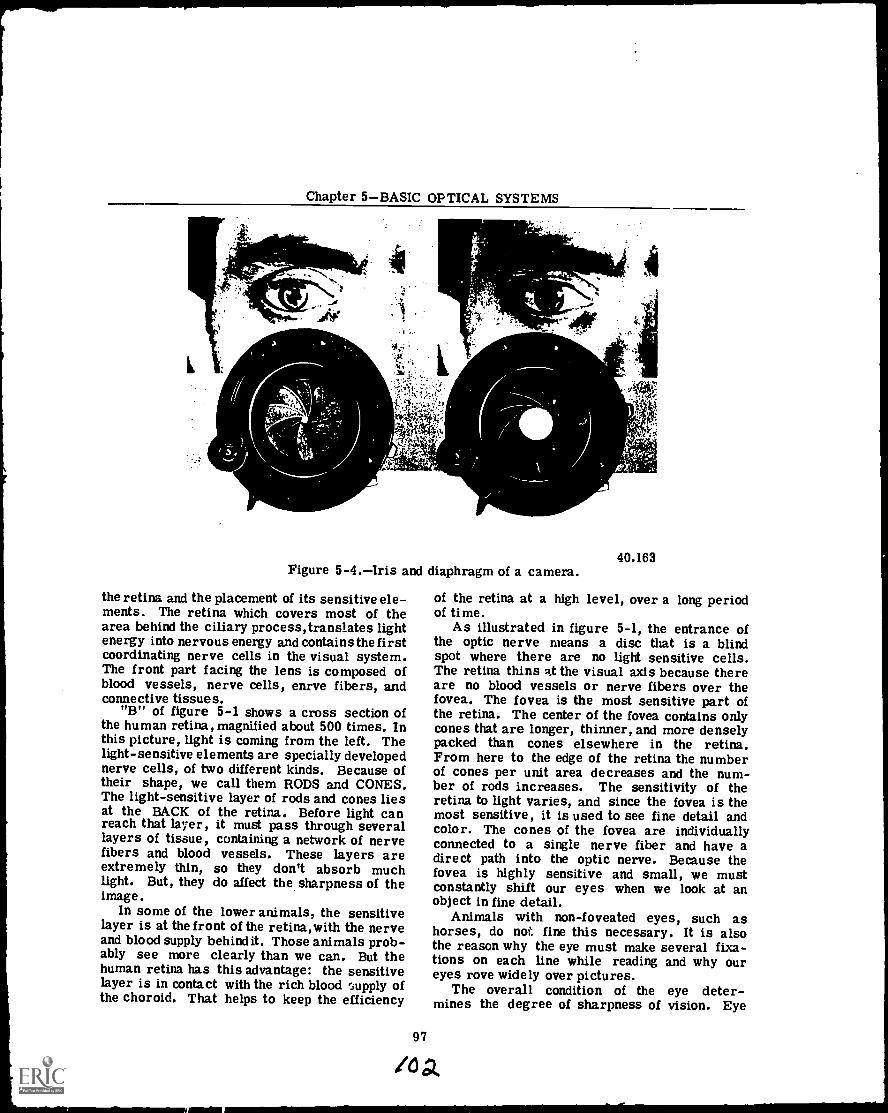
Chapter 5BASIC OPTICAL SYSTEMS
Figure 5-4.Iris and diaphragm of a camera.
the retina and the placement of its sensitive ele-ments. The retina which covers most of thearea behind the ciliary process, translates lightenergy into nervous energy and contains the firstcoordinating nerve cells in the visual system.The front part facing the lens is composed ofblood vessels, nerve cells, enrve fibers, andconnective tissues.
"B" of figure 5-1 shows a cross section ofthe human retina, magnified about 500 times. Inthis picture, light is coming from the left. Thelight-sensitive elements are specially developednerve cells, of two different kinds. Because oftheir shape, we call them RODS and CONES.The light-sensitive layer of rods and cones liesat the BACK of the retina. Before light canreach that layer, it must pass through severallayers of tissue, containing a network of nervefibers and blood vessels. These layers areextremely thin, so they don't absorb muchlight. But, they do affect the sharpness of theimage.
In some of the lower animals, the sensitivelayer is at the front of the retina,with the nerveand blood supply behind it. Those animals prob-ably see more clearly than we can. But thehuman retina has this advantage: the sensitivelayer is in contact with the rich blood supply ofthe choroid. That helps to keep the efficiency
40.163
of the retina at a high level, over a long periodof time.
As illustrated in figure 5-1, the entrance ofthe optic nerve means a disc that is a blindspot where there are no light sensitive cells.The retina thins Rt the visual axis because thereare no blood vessels or nerve fibers over thefovea. The fovea is the most sensitive part ofthe retina. The center of the fovea contains onlycones that are longer, thinner, and more denselypacked than cones elsewhere in the retina.From here to the edge of the retina the numberof cones per unit area decreases and the num-ber of rods increases. The sensitivity of theretina to light varies, and since the fovea is themost sensitive, it is used to see fine detail andcolor. The cones of the fovea are individuallyconnected to a single nerve fiber and have adirect path into the optic nerve. Because thefovea is highly sensitive and small, we mustconstantly shift our eyes when we look at anobject in fine detail.
Animals with non-foveated eyes, such ashorses, do not fine this necessary. It is alsothe reason why the eye must make several fixa-tions on each line while reading and why oureyes rove widely over pictures.
The overall condition of the eye deter-mines the degree of sharpness of vision. Eye
97
/0 a
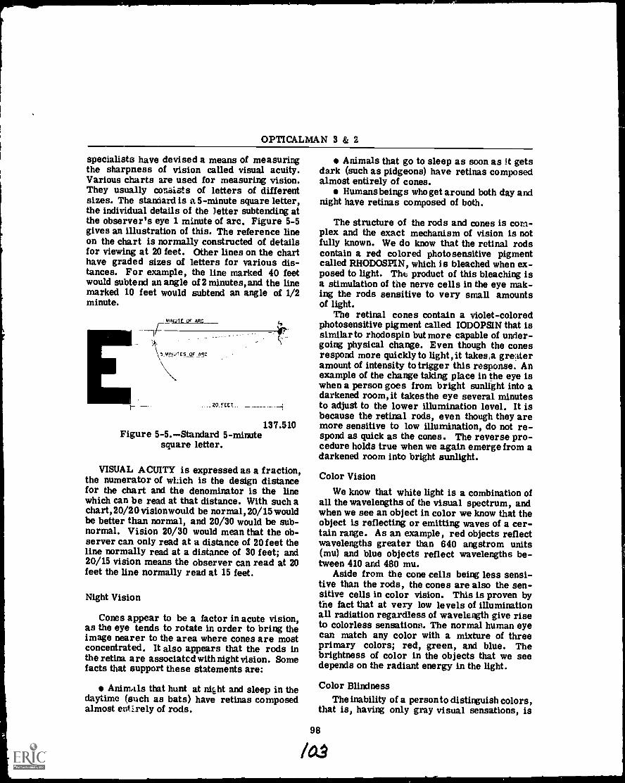
OPTICALMAN 3 & 2
specialists have devised a means of measuringthe sharpness of vision called visual acuity.Various charts are used for measuring vision.They usually con6ists of letters of differentsizes. The standard is a 5-minute square letter,the individual details of the letter subtending atthe observer's eye 1 minute of arc. Figure 5-5gives an illustration of this. The reference lineon the chart is normally constructed of detailsfor viewing at 20 feet. Other lines on the charthave graded sizes of letters for various dis-tances. For example, the line marked 40 feetwould subtend an angle of 2 minutes, and the linemarked 10 feet would subtend an angle of 1/2minute.
I MINUTE OF ARC
5MILUIES OF ARC
20.FEE1
137.510Figure 5-5.Standard 5-minute
square letter.
VISUAL ACUITY is expressed as a fraction,the numerator of which is the design distancefor the chart and the denominator is the linewhich can be read at that distance. With such achart, 20/20 vision would be normal, 20/15 wouldbe better than normal, and 20/30 would be sub-normal. Vision 20/30 would mean that the ob-server can only read at a distance of 20feet theline normally read at a distance of 30 feet; and20/15 vision means the observer can read at 20feet the line normally read at 15 feet.
Night Vision
Cones appear to be a factor in acute vision,as the eye tends to rotate in order to bring theimage nearer to the area where cones are mostconcentrated. It also appears that the rods inthe retina are associated with night vision. Somefacts that support these statements are:
Anim,ils that hunt at night and sleep in thedaytime (such as bats) have retinas composedalmost entirely of rods.
Animals that go to sleep as soon as it getsdark (such as pidgeons) have retinas composedalmost entirely of cones.
Humans beings who get around both day andnight have retinas composed of both.
The structure of the rods and cones is com-plex and the exact mechanism of vision is notfully known. We do know that the retinal rodscontain a red colored photosensitive pigmentcalled RHODOSPIN, which is bleached when ex-posed to light. The product of this bleaching isa stimulation of the nerve cells in the eye mak-ing the rods sensitive to very small amountsof light.
The retinal cones contain a violet-coloredphotosensitive pigment called IODOPSIN that issimilar to rhodospin but more capable of under-going physical change. Even though the conesrespond more quickly to light, it takes,a gre4eramount of intensity to trigger this response. Anexample of the change taking place in the eye iswhen a person goes from bright sunlight into adarkened room, it takes the eye several minutesto adjust to the lower illumination level. It isbecause the retinal rods, even though they aremore sensitive to low illumination, do not re-spond as quick as the cones. The reverse pro-cedure holds true when we again emerge from adarkened room into bright sunlight.
Color Vision
We know that white light is a combination ofall the wavelengths of the visual spectrum, andwhen we see an object in color we know that theobject is reflecting or emitting waves of a cer-tain range. As an example, red objects reflectwavelengths greater than 640 angstrom units(mu) and blue objects reflect wavelengths be-tween 410 and 480 mu.
Aside from the cone cells being less sensi-tive than the rods, the cones are also the sen-sitive cells in color vision. This is proven bythe fact that at very low levels of illuminationall radiation regardless of wavelength give riseto colorless sensationv. The normal human eyecan match any color with a mixture of threeprimary colors; red, green, and blue. Thebrightness of color in the objects that we seedepends on the radiant energy in the light.
Color BlindnessThe inability of a person to distinguish colors,
that is, having only gray visual sensations, is
98
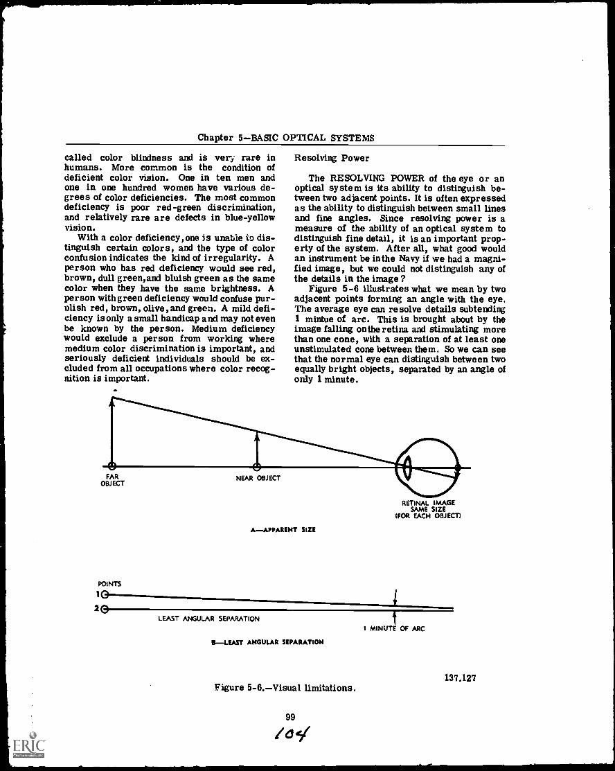
Chapter 5BASIC OPTICAL SYSTEMS
called color blindness and is very rare inhumans. More common is the condition ofdeficient color vision. One in ten men andone in one hundred women have various de-grees of color deficiencies. The most commondeficiency is poor red-green discrimination,and relatively rare are defects in blue-yellowvision.
With a color deficiency, one is unable to dis-tinguish certain colors, and the type of colorconfusion indicates the kind of irregularity. Aperson who has red deficiency would see red,brown, dull green, and bluish green as the samecolor when they have the same brightness. Aperson with green deficiency would confuse pur-plish red, brown, olive, and green. A mild defi-ciency is only a small handicap and may not evenbe known by the person. Medium deficiencywould exclude a person from working wheremedium color discrimination is important, andseriously deficient individuals should be ex-cluded from all occupations where color recog-nition is important.
Resolving Power
The RESOLVING POWER of the eye or anoptical system is its ability to distinguish be-tween two adjacent points. It is often expressedas the ability to distinguish between small linesand fine angles. Since resolving power is ameasure of the ability of an optical system todistinguish fine detail, it is an important prop-erty of the system. After all, what good wouldan instrument be in the Navy if we had a magni-fied image, but we could not distinguish any ofthe details in the image ?
Figure 5-6 illustrates what we mean by twoadjacent points forming an angle with the eye.The average eye can resolve details subtending1 mintue of arc. This is brought about by theimage falling on the retina and stimulating morethan one cone, with a separation of at least oneunstimulated cone between them. So we can seethat the normal eye can distinguish between twoequally bright objects, separated by an angle ofonly 1 minute.
POINTS
1
2
RETINAL IMAGESAME SIZE
(FOR EACH OBJECT)
A-APPARENT SIZE
LEAST ANGULAR SEPARATION
0-LEAST ANGULAR SEPARATION
Figure 5-6.Visual limitations.
1 MINUTE OF ARC
137.127
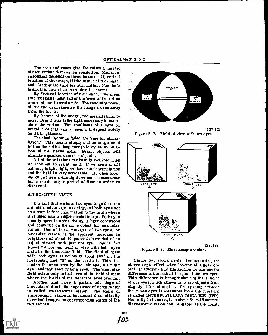
OPTICALMAN 3 & 2
The rods and cones give the retina a mosaicstructure that determines resolution. Maximumresolution depends on three factors: (1) retinallocation of the image, (2) the nature of the image,and (3)adequate time for stimulation. Now let'sbreak this down into more detailed terms.
By "retinal location of the image," we meanthat the image must fall on the fovea of the retinawhere vision is most acute. The resolving powerof the eye decreases as the image moves awayfrom the fovea.
By "nature of the image,"we mean its bright-ness. Brightness is the light necessary to stim-ulate the retina. The smallness of a light orbright spot that can k.)- seen will depend solelyon its brightness.
The final factor is "adequate time for stimu-lation." This means simply that an image mustfall on the retina long enough to cause stimula-tion of the nerve cells. Bright objects willstimulate quicker than dim objects.
All of these factors can be fully realized whenwe look out to sea at night. If we see a smallbut very bright light, we have quick stimulationand the light is very noticeable. If, when look-ing out,we see a dim light,we must concentratefor a much longer period of time in order todiscern it.
STEROSCOPIC VISION
The fact that we have two eyes to guide us isa decided advantage in seeing,and both eyes actas a team to feed information to the brain whereit is fused into a single mentalimage. Both eyesusually operate under the same light conditionsand converge on the same object for binocularvision. One of the advantages of two eyes, orbinocular vision, is the apparent increase inbrightness of about 20 percent above that of anobject viewed with just one eye. Figure 5-7shows the normal field of view with both eyesand also the binocular field. The field of viewwith both eyes is normally about 160° on thehorizontal, and 70° on the vertical. This in-cludes the area seen by the left eye, the righteye, and that seen by both eyes. The binocularfield exists only in that area of the field of viewwhere the fields of the separate eyes overlap.
Another and more important advantage ofbinocular vision is the experience of depth, whichis called stereoscopic vision. The basis ofstereoscopic vision is horizontal dissimilarityof retinal images on corresponding points of thetwo retinas.
BINOCULARFIELD
FIE 0OF
LEFT EYEIflOf
RIGHT EYE
137.128Figure 5-7.Field of view with two eyes.
100
LEFTA
EYE RIGHT EYEB
BOTH EYESC
137.129Figure 5-8.Stereoscopic vision.
Figure 5-8 shows a cube demonstrating thestereoscopic effect when looking at a near ob-ject. In studying this illustration we can see thedifference in the retinal images of the two eyes.This difference is brought about by the spacingof our eyes, which allows usto see objects fromslightly different angles. The spacing betweenthe human eyes is measured from the pupil andis called INTERPUPILLARY DISTANCE (IPD).Normally in humans, it is about 64 millimeters.Stereoscopic vision can be stated as the ability
las
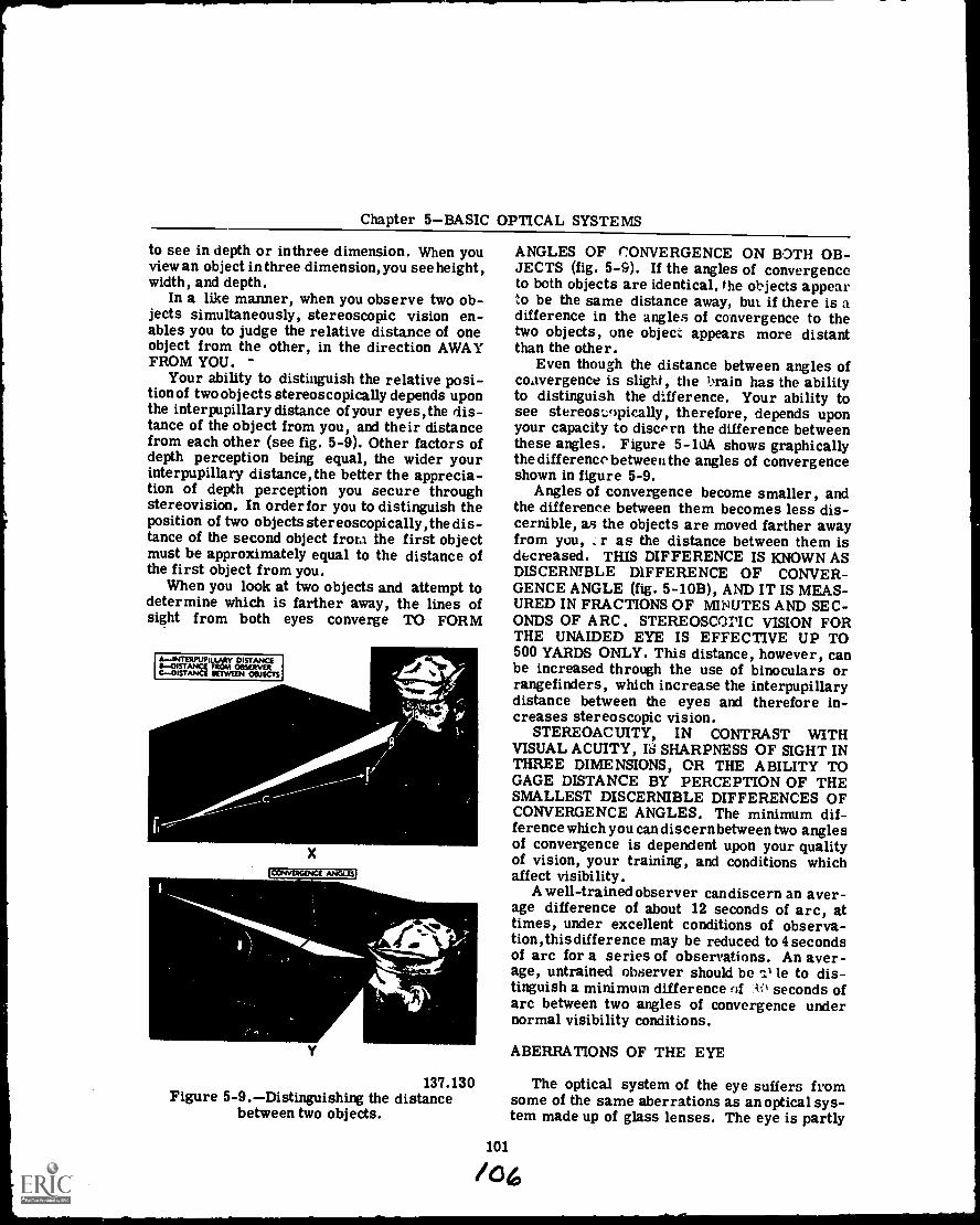
Chapter 5BASIC OPTICAL SYSTEMS
to see in depth or in three dimension. When youview an object in three dimension, you see height,width, and depth.
In a like manner, when you observe two ob-jects simultaneously, stereoscopic vision en-ables you to judge the relative distance of oneobject from the other, in the direction AWAYFROM YOU.
Your ability to distinguish the relative posi-tion of two objects stereoscopically depends uponthe interpupillary distance of your eyes,the dis-tance of the object from you, and their distancefrom each other (see fig. 5-9). Other factors ofdepth perception being equal, the wider yourinterpupillary distance,the better the apprecia-tion of depth perception you secure throughstereovision. In order for you to distinguish theposition of two objects stereoscopically, the dis-tance of the second object from the first objectmust be approximately equal to the distance ofthe first object from you.
When you look at two objects and attempt todetermine which is farther away, the lines ofsight from both eyes converge TO FORM
AINTERPUPILLARY DISTANCEIIDISTANCE FROM OOSERVERCDISTANCE SEMEN OBJECTS
X
71WERIFTIC---INGLE3
Y
137.130Figure 5-9.Distinguishing the distance
between two objects.
ANGLES OF CONVERGENCE ON BOTH OB-JECTS (fig. 5-9), If the angles of convergenceto both objects are identical, the objects appearto be the same distance away, but if there is adifference in the angles of convergence to thetwo objects, one object appears more distantthan the other.
Even though the distance between angles ofconvergence is slight, the 'rain has the abilityto distinguish the difference. Your ability tosee stereosLopically, therefore, depends uponyour capacity to discern the difference betweenthese angles. Figure 5-10A shows graphicallythe difference between the angles of convergenceshown in figure 5-9.
Angles of convergence become smaller, andthe difference between them becomes less dis-cernible, as the objects are moved farther awayfrom you, r as the distance between them isdecreased. THIS DIFFERENCE IS KNOWN ASDISCERNIBLE DIFFERENCE OF CONVER-GENCE ANGLE (fig. 5-10B), AND IT IS MEAS-URED IN FRACTIONS OF MIPUTES AND SEC-ONDS OF ARC. STEREOSCOPIC VISION FORTHE UNAIDED EYE IS EFFECTIVE UP TO500 YARDS ONLY. This distance, however, canbe increased through the use of binoculars orrangefinders, which increase the interpupillarydistance between the eyes and therefore in-creases stereoscopic vision.
STEREOACUITY, IN CONTRAST WITHVISUAL ACUITY, 18 SHARPNESS OF SIGHT INTHREE DIMENSIONS, OR THE ABILITY TOGAGE DISTANCE BY PERCEPTION OF THESMALLEST DISCERNIBLE DIFFERENCES OFCONVERGENCE ANGLES. The minimum dif-ference which you can discernbetween two anglesof convergence is dependent upon your qualityof vision, your training, and conditions whichaffect visibility.
A well-trained observer candiscern an aver-age difference of about 12 seconds of arc, attimes, under excellent conditions of observa-tion,this difference may be reduced to 4 secondsof arc for a series of observations. An aver-age, untrained observer should be le to dis-tinguish a minimum difference of io seconds ofarc between two angles of convergence undernormal visibility conditions.
ABERRATIONS OF THE EYE
The optical system of the eye suffers fromsome of the same aberrations as an optical sys-tem made up of glass lenses. The eye is partly
101
/06
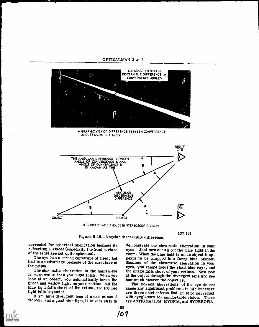
OPTICALMAN 3 & 2
SUBTRAC r TO OBTAINDISCERNIBLE DIFFERENCE OF
CONVERGENCE ANGLES
A GRAPHIC VIEW OF DIFFERENCE BETWEEN CONVERGENCEANGLES SHOWN IN X AND Y
OBJECT
THE ANGULAR DIFFERENCE BETWEENANGLE OF CONIVERGENCE A AND
ANGLE OF ONVERGENCE BIS KNOWN AS THE
ANGULARDISCERNIBLEDIFFERENCE
OBJECT
A
B CONVERGENCE ANGLES IN STEREOSCOPIC VISION
Figure 5-10.Angular discernible difference.
corrected for spherical aberration because itsrefracting surfaces (especially the front surfaceof the lens) are not quite spherical.
The eye has a strong curvature of field, butthat is an advantage because of the curvature ofthe retina.
The chromatic aberration in the human eyeis much woi ie than you might think. When youlook at an object, you automatically focus thegreen and yellow light on your retinas, but theblue light falls short of the retina, and this redlight falls beyond it.
If y,-.11 have divergent lens of about minus 2dioptez, And a good blue light, it is very easy to
102
kiGI:T1
LEFTEYE
137.131
demonstrate the chromatic aberration in youreyes. Just turn out all but the blue light in theroom. When the blue light is on an object it ap-pears to be wrapped in a fuzzy blue blanket.Because of the chromatic aberration in youreyes, you cannot focus the short blue rays, andthe image falls short of your retinas. Now lookat the object through the divergent lens and seehow much clearer the object is.
The normal aberrations of the eye do notcause any significant problems in life but thereare three chief defects that must be correctedwith eyeglasses for comfortable vision. Theseare ASTIGMATISM, MYOPIA, and HYPEROPIA.
/o?
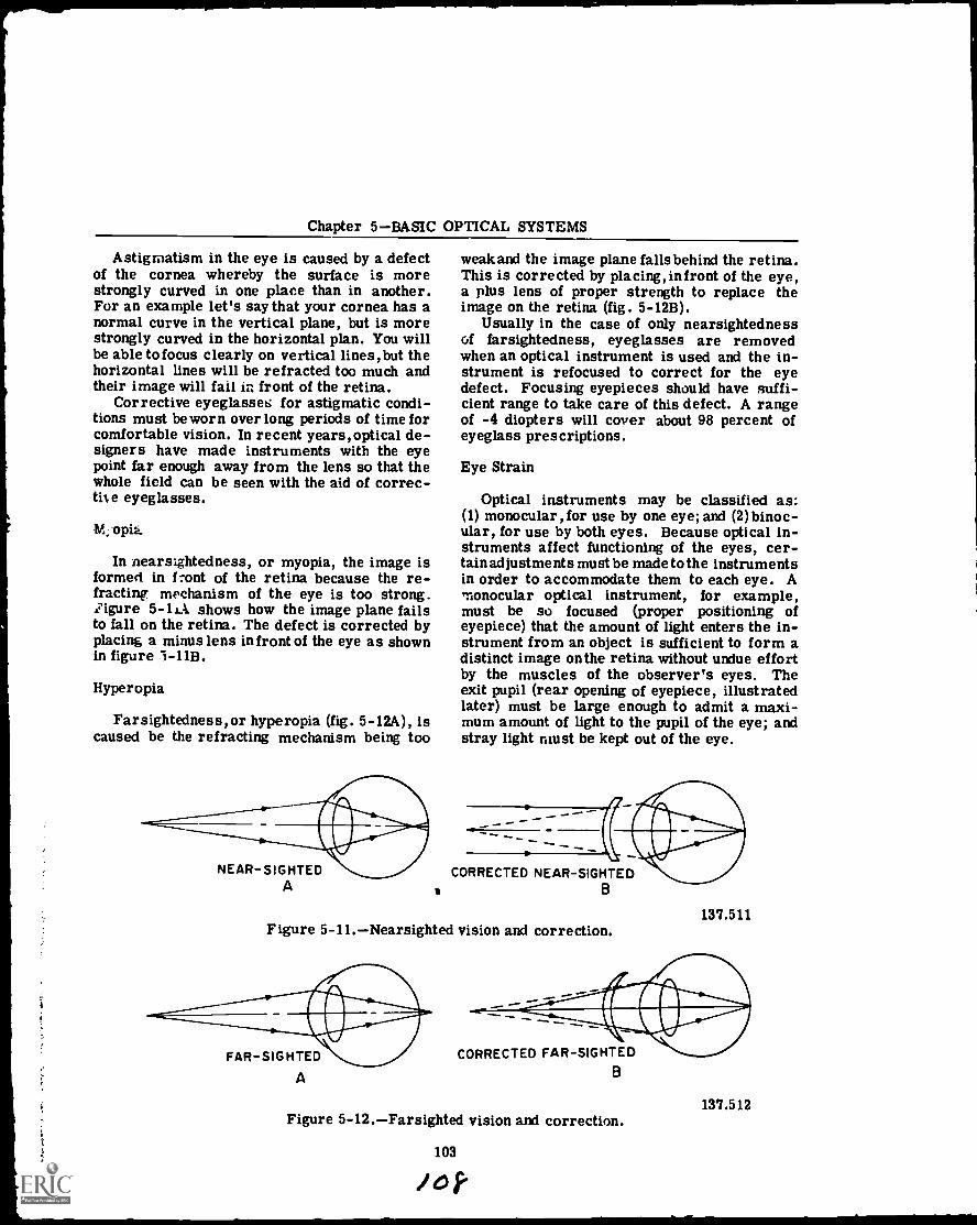
Chapter 5BASIC OPTICAL SYSTEMS
Astigmatism in the eye is caused by a defectof the cornea whereby the surface is morestrongly curved in one place than in another.For an example let's say that your cornea has anormal curve in the vertical plane, but is morestrongly curved in the horizontal plan. You willbe able to focus clearly on vertical lines, but thehorizontal lines will be refracted too much andtheir image will fail Ir. front of the retina.
Corrective eyeglasses for astigmatic condi-tions must be worn over long periods of time forcomfortable vision. In recent years,optical de-signers have made instruments with the eyepoint far enough away from the lens so that thewhole field can be seen with the aid of correc-the eyeglasses.
116;oph.
In nearsightedness, or myopia, the image isformed in front of the retina because the re-fracting mechanism of the eye is too strong.figure 5-41 shows how the image plane failsto fall on the retina. The defect is corrected byplacing a minus lens in front of the eye as shownin figure 1-11B.
Hyperopia
Farsightedness,or hyperopia (fig. 5-12A), iscaused be the refracting mechanism being too
NEAR-SIGHTEDA
weak and the image plane falls behind the retina.This is corrected by placing,infront of the eye,a plus lens of proper strength to replace theimage on the retina (fig. 5-12B).
Usually in the case of only nearsightednessof farsightedness, eyeglasses are removedwhen an optical instrument is used and the in-strument is refocused to correct for the eyedefect. Focusing eyepieces should have suffi-cient range to take care of this defect. A rangeof -4 diopters will cover about 98 percent ofeyeglass prescriptions.
Eye Strain
Optical instruments may be classified as:(1) monocular, for use by one eye; and (2)binoc-ular, for use by both eyes. Because optical in-struments affect functioning of the eyes, cer-tain adjustments must be made to the instrumentsin order to accommodate them to each eye. Amonocular optical instrument, for example,must be so focused (proper positioning ofeyepiece) that the amount of light enters the in-strument from an object is sufficient to form adistinct image onthe retina without undue effortby the muscles of the observer's eyes. Theexit pupil (rear opening of eyepiece, illustratedlater) must be large enough to admit a maxi-mum amount of light to the pupil of the eye; andstray light must be kept out of the eye.
CORRECTED NEAR-SIGHTEDB
Figure 5-11.Nearsighted vision and correction.
FAR-SIGHTED
A
137.511
CORRECTED FAR-SIGHTEDB
Figure 5-12.Farsighted vision and correction.137.512
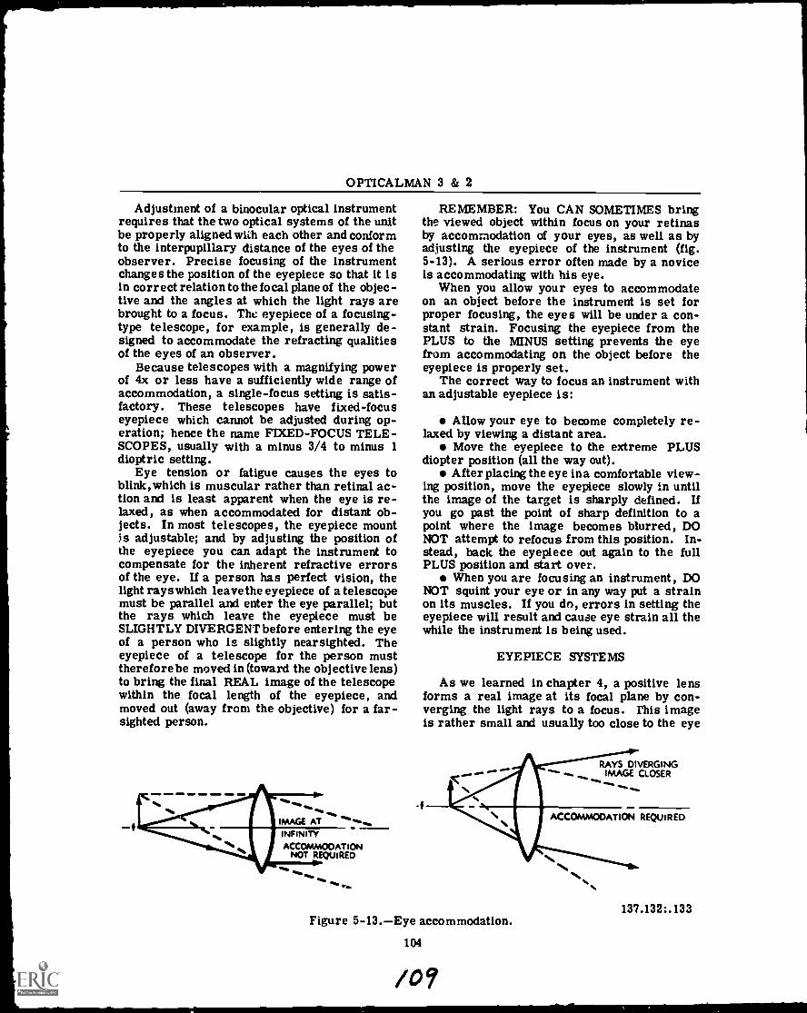
OPTICALMAN 3 & 2
Adjustment of a binocular optical instrumentrequires that the two optical systems of the unitbe properly aligned vigil each other and conformto the interpupillary distance of the eyes of theobserver. Precise focusing of the instrumentchanges the position of the eyepiece so that it isin correct relation to the focal plane of the objec-tive and the angles at which the light rays arebrought to a focus. The: eyepiece of a focusing-type telescope, for example, is generally de-signed to accommodate the refracting qualitiesof the eyes of an observer.
Because telescopes with a magnifying powerof 4x or less have a sufficiently wide range ofaccommodation, a single-focus setting is satis-factory. These telescopes have fixed-focuseyepiece which cannot be adjusted during op-eration; hence the name FIXED-FOCUS TELE-SCOPES, usually with a minus 3/4 to minus 1dioptric setting.
Eye tension or fatigue causes the eyes toblink,which is muscular rather than retinal ac-tion and is least apparent when the eye is re-laxed, as when accommodated for distant ob-jects. In most telescopes, the eyepiece mountis adjustable; and by adjusting the position ofthe eyepiece you can adapt the instrument tocompensate for the inherent refractive errorsof the eye. If a person has perfect vision, thelight rays which leave the eyepiece of a telescopemust be parallel and enter the eye parallel; butthe rays which leave the eyepiece must beSLIGHTLY DIVERGENT before entering the eyeof a person who is slightly nearsighted. Theeyepiece of a telescope for the person musttherefore be moved in (toward the objective lens)to bring the final REAL image of the telescopewithin the focal length of the eyepiece, andmoved out (away from the objective) for a far-sighted person.
=MI ,1 41. ONO
INFINITYACCOMMODATION
NOT REQUIRED
REMEMBER: You CAN SOMETIMES bringthe viewed object within focus on your retinasby accommodation of your eyes, as well as byadjusting the eyepiece of the instrument (fig.5-13). A serious error often made by a noviceis accommodating with his eye.
When you allow your eyes to accommodateon an object before the instrument is set forproper focusing, the eyes will be under a con-stant strain. Focusing the eyepiece from thePLUS to the MINUS setting prevents the eyefrom accommodating on the object before theeyepiece is properly set.
The correct way to focus an instrument withan adjustable eyepiece is:
Allow your eye to become completely re-laxed by viewing a distant area.
Move the eyepiece to the extreme PLUSdiopter position (all the way out).
After placing the eye in a comfortable view-ing position, move the eyepiece slowly in untilthe image of the target is sharply defined. Ifyou go past the point of sharp definition to apoint where the image becomes blurred, DONOT attempt to refocus from this position. In-stead, back the eyepiece out again to the fullPLUS position and start over.
When you are focusing an instrument, DONOT squint your eye or in any way put a strainon its muscles. If you do, errors in setting theeyepiece will result and cause eye strain all thewhile the instrument is being used.
EYEPIECE SYSTEMS
As we learned in chapter 4, a positive lensforms a real image at its focal plane by con-verging the light rays to a focus. This imageis rather small and usually too close to the eye
i4fFigure 5-13.Eye accommodation.
104
/0?
RAYS DIVERGINGIMAGE CLOSER
ACCOMMODATION REQUIRED
137.132:.133
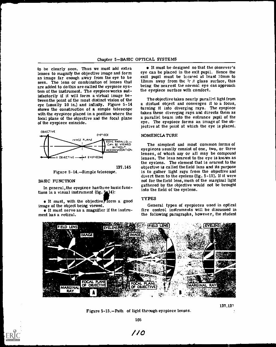
Chapter 5BASIC OPTICAL SYSTEMS
to be clearly seen. Thus we must add extralenses to magnify the objective image and forman image far enough away from the eye to beseen. The lens or combination of lenses thatare added to do this are called the eyepiece sys-tem of the instrument. The eyepiece works sat-isfactorily if it will form a virtual image be-tween the point of the most distinct vision of theeye (usually 10 in.) and infinity. Figure 5-14shows the construction of a simple telescopewith the eyepiece placed in a position where thefocal plane of the objective and the focal planeof the eyepiece coincide.
OBJECTIVE
ivAGE °LANE1
OBACTIvE E EYEPIECEi
EYEPIECE
RAYS PARALLEL-CAIN BE VIEwED
wiTHOuTACCOMMODATION
137.145Figure 5-14.Simple telescope.
BASIC FUNCTION
In general,the eyepiece has three basic func-tions in a visual instrument (fig. 4):
It must, with the objective, orm a goodimage of the object being viewed.
It must serve as a magnifier if the instru-ment has a retical.
It must be designed so that the observer'seye can be placed in the exit pupil. Hence theexit pupil must be located at least 10mm to12mm away from the 1: ;t glass surface, thisbeing the nearest the normal eye can approachthe eyepiece surface with comfort.
The objective takes nearly parallel light froma distant object and converges it to a focus,turning it into diverging rays. The eyepiecetakes these diverging rays and directs them asa parallel beam into the entrance pupil of theeye. The eyepiece forms an image of the ob-jective at the point at which the eye is placed.
NOMENCLATURE
The simplest and most common forms ofeyepieces usually consist of one, two, or threelenses, of which any or all may be compoundlenses. The lens nearest to the eye is known asthe eyelens. The element that is nearest to theobjective is called the field lens and its purposeis to gather light rays from the objective anddivert them to the eyelens (fig. 5-15). If it werenot for the field lens, much of the marginal lightgathered by the objective would not be broughtinto the field of the eyelens.
TYPESGeneral types of eyepieces used in optical
fire control instruments will be discussed inthe following paragraphs, however, the student
137.137Figure 5-15.Path of light through eyepiece lenses.
105
//0
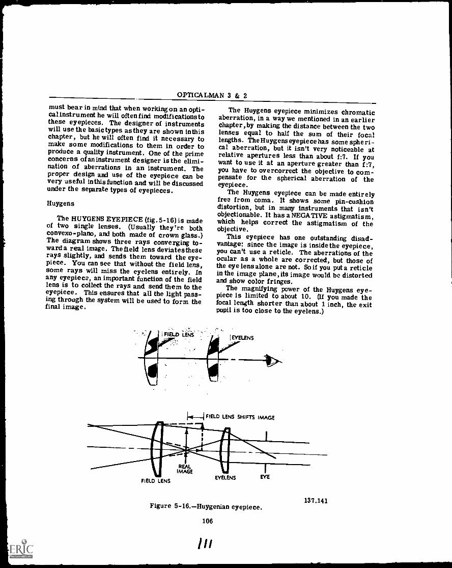
OPTICALMAN 3 & 2
must bear in mind that when working on an opti-cal instrument he will often find modifications tothese eyepieces. The designer of instrumentswill use the basic types as they are shown inthischapter, but he will often find it necessary tomake some modifications to them in order toproduce a quality instrument. One of the primeconcerns of an instrument designer is the elimi-nation of aberrations in an instrument. Theproper design and use of the eyepiece can bevery useful inthis function and will be discussedunder the separate types of eyepieces.
Huygens
The HUYGENS EYEPIECE (fig. 5-16) is madeof two single lenses. (Usually they're bothconvexo-plano, and both made of crown glass.)The diagram shows three rays converging to-ward a real image. The field lens deviatestheserays slightly, and sends them toward the eye-piece. You can see that without the field lens,some rays will miss the eyelens entirely. Inany eyepiece, an important function of the fieldlens is to collect the rays and send them to theeyepiece. This ensures that all the light pass-ing through the system will be used to form thefinal image.
The Huygens eyepiece minimizes chromaticaberration, in a way we mentioned in an earlierchapter,by making the distance between the twolenses equal to half the sum of their focallengths. The Huygens eyepiece has some spheri-cal aberration, but it isn't very noticeable atrelative apertures less than about f:7. If youwant to use it at an aperture greater than f:7,you have to overcorrect the objective to com-pensate for the spherical aberration of theeyepiece.
The Huygens eyepiece can be made entirelyfree from coma. It shows some pin-cushiondistortion, but in many instruments that isn'tobjectionable. It has a NEGATIVE astigmatism,which helps correct the astigmatism of theobjective.
This eyepiece has one outstanding disad-vantage: since the image is inside the eyepiece,you can't use a reticle. The aberrations of theocular as a whole are corrected, but those ofthe eye lens alone are not. So if you put a reticlein the image plane, its image would be distortedand show color fringes.
The magnifying power of the Huygens eye-piece is limited to about 10. (If you made thefocal length shorter than about 1 inch, the exitpupil is too close to the eyelens.)
1.4_1 FIELD LENS SHIFTS IMAGE
aNMI11 IMAGE
L
FIELD LENSEYELENS EYE
Figure 5-16.Huygenian eyepiece.
106
ill
137.141

Chapter 5BASIC OPTICAL SYSTEMS
Ramsden
Figure 5-17 shows the RAMSDEN EYEPIECE.It's made of two piano- convex lenses of equalfocal length. The distance between them isequal to about two-thirds of that length. Thearrow is the real image formed by the erectinglens. As you can see,the eyepiece forms an en-larged virtual image at infinity.
!ran 4411124.-,;;:5*?, sayeirisZ.VIV,S9r e
ori.
FIELD LENS EYELENS
/ I .4._2/3 I EITHER LENS
137.138Figure 5-17.Ramsden eyepiece.
The Ramsden eyepiece has one outstandingdisadvantage: its chromatic aberration is ratherserious. It has no coma, and all its other aber-rations are less than those of the Huygens eye-piece. Besides controlling all the aberrationsexcept color, the Ramsden has this advantageover the Huygens: since the real image is out-side the eyepiece, you can put a reticle in theimage plane.
Except for its chromatic aberration, theRamsden is a desirable eyepiece. For any givenfocal length, its eye distance is about 1.5 timesthat of the Huygens, so you can use a highermagnifying power. And the aberrations of theRamsden are increased less than those of theHuygens by slight variations in the focal lengthof the objective. But the only way you can elim-inate the chromatic aberration is by formingthe image inside the eyepiece, and then you can'tuse a reticle.
Kellner
The Kellner eyepiece is a modification of theRamsden. Figure 5-18 will serve to illustrate
the Kellner; the only difference is that the eyelens is a doublet. The Kellner keeps most ofthe advantages of the Ramsden, and reduces thechromatic aberration. Spherical aberration isslightly grf..ter, but distortion is less. Toeliminate the chromatic aberration completely,you'd have to put the :field lens in the plane ofthe real image. And then you couldn't use areticle. Most instrumuits that use a Ramsdeneyepiece have the field lens a short distancebeyond the image plane. They sacrifice a partof the color correction in order to use a reticle.
107
Symmetrical and Two DoubletEyepieces
Symmetrical and two-doublet eyepieces areconstructed of two cemented, achromatic doub-lets (fairly close together) with their positiveelements facing each other. If the doublets areidentical in every respect (diameters, focallengths, thickness and index of refraction), theeyepiece is symmetrical. If the doublets differin one respect or another, however, they areconsidered as a TWO-DOUBLET eyepiece. Theeyelens of the two-doublet eyepiece is gen-erally slightly smaller in diameter and has ashorter focal length than its field lens. Doub-lets in a symmetrical eyepiece, on the otherhand, ARE IDENTICAL IN EVERY RESPECTAND CAN BE INTERCHANGED (fig. 5-19).
Symmetrical and two-doublet eyepieces areoften used in fire control instruments whichrecoil. The eye distance on these instrumentsmust be fairly long, to prevent the eyepiecefrom striking the gunner's eye. These eye-pieces may alsobe used interrestial telescopes(not only in gunsight telescopes), or in anyother telescope designed to carry them.
A symmetrical eyepiece provides long eyerelief, because it has a large exit pupil and lowmagnification, qualities which ensure eye relief.For this reason, symmetrical eyepiecesalongwith Kellnerare used extensively in opticalinstruments, particularly rifle scoped andgunsights.
Orthoscopic
The orthoscopic Pyepiece is illustrated infigure 5-20. It employs a planoconvex tripletfield lens and a single planoconvex eyelens withthe curved surface of the field lens facing thecurved surface of the eyelens. It is free of dis-tortion and is useful in high-power telescopes
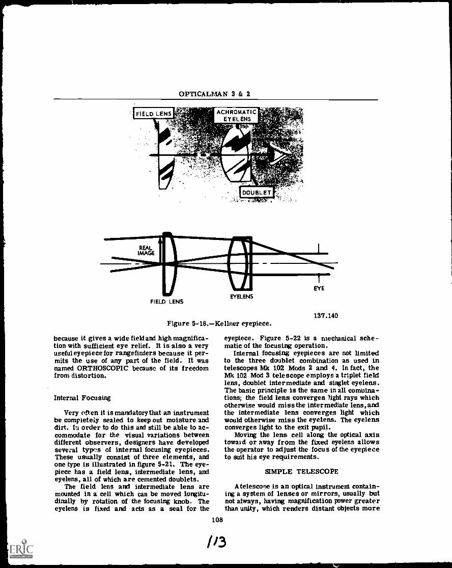
Figure 5-18.Kellner eyepiece.
because it gives a wide field and high magnifica-tion with sufficient eye relief. It is also a veryuseful eyepiece for rangefinders because it per-mits the use of any part of the field. It wasnamed ORTHOSCOPIC because of its freedomfrom distortion.
Internal Focusing
Very often it is mandatory that an instrumentbe completely sealed to keep out moisture anddirt. order to do this and still be able to ac-commodate for the visual variations betweendifferent observers, designers have developedseveral type's of internal focusing eyepieces.These usually consist of three elements, andone type is illustrated in figure 5-21. The eye-piece has a field lens, intermediate lens, andeyelens, all of which are cemented doublets.
The field lens and intermediate lens aremounted in a cell which can be moved longitu-dinally by rotation of the focusing knob. Theeyelens is fixed and acts as a seal for the
108
137.140
eyepiece. Figure 5-22 is a mechanical sche-matic of the focusing operation.
Internal focusing eyepieces are not limitedto the three doublet combination as used intelescopes Mk 102 Mods 2 and 4. In fact, theMk 102 Mod 3 telescope employs a triplet fieldlens, doublet intermediate and singlet eyelens.The basic principle is the same in all comuina-tions; the field lens converges light rays whichotherwise would miss the intermediate lens, andthe intermediate lens converges light whichwould otherwise miss the eyelens. The eyelensconverges light to the exit pupil.
Moving the lens cell along the optical axistoward or away from the fixed eyelens allowsthe operator to adjust the focus of the eyepieceto suit his eye requirements.
SIMPLE TELESCOPE
Atelescone is an optical instrument contain-ing a system of lenses or mirrors, usually butnot always, having magnification power greaterthan unity, which renders distant objects more
"3
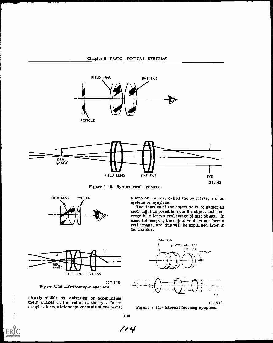
Chapter 5BASIC OPTICAL SYSTEMS
FIELD LENS EYELENS
REALIMAGE
RETICLE
FIELD LENS EYELENS
Figure 5-19.Syntmetrical eyepiece.
FIELD LENS EYELENS
4111
1
EYE
137.142
a lens or mirror, called the objective, and aneyelens or eyepiece.
The function of the objective is to gather asmuch light as possible from the object and con-verge it to form a real image of that object. Insome telescopes, the objective does not form areal image, and this will be explained later inthe chapter.
FEW LENS
FIELD LENS EYELENS
137.143Figure 5-20.Orthoscopic eyepiece.
clearly visible by enlarging or accentuatingtheir images on the retina of the eye. In itssimplest form,a telescope consists of two parts;
109
141
137.513Figure 5-21.Internal focusing eyepiece.
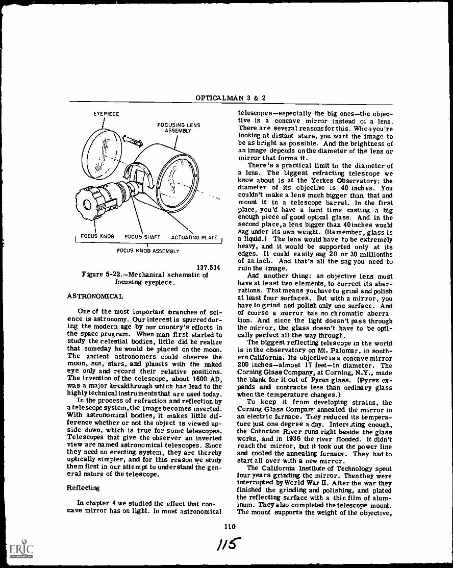
OPTICALMAN 3 & 2
EYEPIECE
FOCUSING LENSASSEMBLY
I FOCUS KNOB FOCUS SHAFT ACTUATING PLATE
FOCUS KNOB ASSEMBLY
137.514Figure 5-22.Mechanical schematic of
focusing eyepiece.
ASTRONOMICAL
One of the most important branches of sci-ence is astronomy. Our interest is spurred dur-ing the modern age by our country's efforts inthe space program. When man first started tostudy the celestial bodies, little did he realizethat someday he would be placed on the moon.The ancient astronomers could observe themoon, sun, stars, and planets with the nakedeye only and record their relative positions.The invention of the telescope, about 1600 AD,was a major breakthrough which has lead to thehighly technical instruments that are used today.
In the process of refraction and reflection bya telescope system, the image becomes inverted.With astronomical bodies, it makes little dif-ference whether or not the object is viewed up-side down, which is true for some telescopes.Telescopes that give the observer an invertedview are named astronomical telescopes. Sincethey need no erecting system, they are therebyoptically simpler, and for this reason we studythem first in our attempt to understand the gen-eral nature of the telescope.
Reflecting
In chapter 4 we studied the effect that con-cave mirror has on light. In most astronomical
telescopesespecially the big onesthe objec-tive is a concave mirror instead or a lens.There are several reasons for this. Wheci you'relooking at distant stars, you want the image tobe as bright as possible. And the brightness ofan image depends on the diameter of the lens ormirror that forms it.
There's a practical limit to the diameter ofa lens. The biggest refracting telescope weknow about is at the Yerkes Observatory; thediameter of its objective is 40 inches. Youcouldn't make a lens much bigger than that andmount it in a telescope barrel. In the firstplace, you'd have a hard time casting a bigenough piece of good optical glass. And in thesecond place, a lens bigger than 40 inches wouldsag under its own weight. (Remember, glass isa liquid.) The lens would have to be extremelyheavy, and it would be supported only at itsedges. It could easily sag 20 or 30 millionthsof an inch. And that's all the sag you need toruin the image.
And another thing: an objective lens musthave at least two elements, to correct its aber-rations. That means you have to grind and polishat least four surfaces. But with a mirror, youhave to grind and polish only one surface. Andof course a mirror has no chromatic aberra-tion. And since the light doesn't pass throughthe mirror, the glass doesn't have to be opti-cally perfect all the way through.
The biggest reflecting telescope in the worldis in the observatory on Mt. Palomar, in south-ern California. Its objective is a concave mirror200 inchesalmost 17 feetin diameter. TheCorning Glass Company, at Corning, N.Y., madethe blank for it out of Pyrex glass. (Pyrex ex-pands and contracts less than ordinary glasswhen the temperature changes.)
To keep it from developing strains, theCorning Glass Company annealed the mirror inan electric furnace. They reduced its tempera-ture just one degree a day. Interesting enough,the Cohocton River runs right beside the glassworks, and in 1936 the river flooded. It didn'treach the mirror, but it took out the power lineand cooled the annealing furnace. They had tostart all over with a new mirror.
The California Institute of Technology spentfour years grinding the mirror. Thenthey wereinterrupted by World War II. After the war theyfinished the grinding and polishing, and platedthe reflecting surface with a thin film of alum-inum. They also completed the telescope mount.The mount supports the weight of the objective,
110
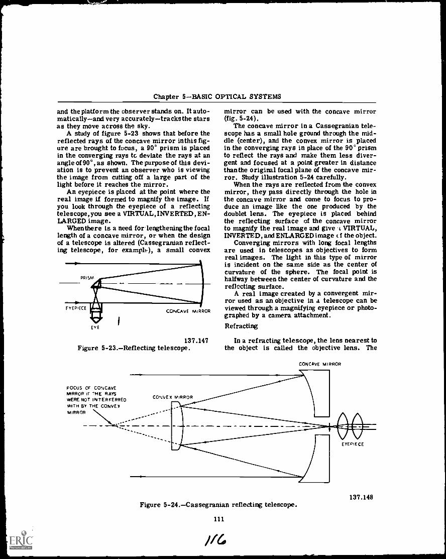
Chapter 5BASIC OPTICAL SYSTEMS
and the platform the observer stands on. It auto-maticallyand very accuratelytracks the starsas they move across the sky.
A study of figure 5-23 shows that before thereflected rays of the concave mirror inthis fig-ure are brought to focus, a 90° prism is placedin the converging rays tc deviate the rays at anangle of 90°, as shown. The purpose of this devi-ation is to prevent an observer who is viewingthe image from cutting off a large part of thelight before it reaches the mirror.
An eyepiece is placed at the point where thereal image U formed to magnify the image. Ifyou look through the eyepiece of a reflectingtelescope, you see a VIRTUAL, INVERTED, EN-LARGED image.
Whenthere is a need for lengthening the focallength of a concave mirror, or when the designof a telescope is altered (Cassegranian reflect-ing telescope, for examplt-), a small convex
mirror can be used with the concave mirror(fig. 5-24).
The concave mirror in a Cassegranian tele-scope has a small hole ground through the mid-dle (center), and the convex mirror is placedin the converging rays in place of the 900 prismto reflect the rays and make them less diver-gent and focused at a point greater in distancethan the original focal plane of the concave mir-ror. Study illustration 5-24 carefully.
When the rays are reflected from the convexmirror, they pass directly through the hole inthe concave mirror and come to focus to pro-duce an image like the one produced by thedoublet lens. The eyepiece is placed behindthe reflecting surface of the concave mirrorto magnify the real image and give t VIRTUAL,INVERTED, and ENLARGED image c if the object.
Converging mirrors with long focal lengthsare used in telescopes as objectives to formreal images. The light in this type of mirroris incident on the same side as the center ofcurvature of the sphere. The focal point ishallway between the center of curvature and thereflecting surface.
A real image created by a convergent mir-ror used as an objective in a telescope can beviewed through a magnifying eyepiece or photo-graphed by a camera attachment.Refracting
137.147 In a refracting telescope, the lens nearest tothe object is called the objective lens. TheFigure 5-23.Reflecting telescope.
FOCUS OF CONCAVEMIRROR IF THE RAYSWERE NOT INTER FERREOWITH BY THE CONVEXMIRROR
CONCAVE MIRROR
Figure 5-24.Cassegranian reflecting telescope.
111
137.148
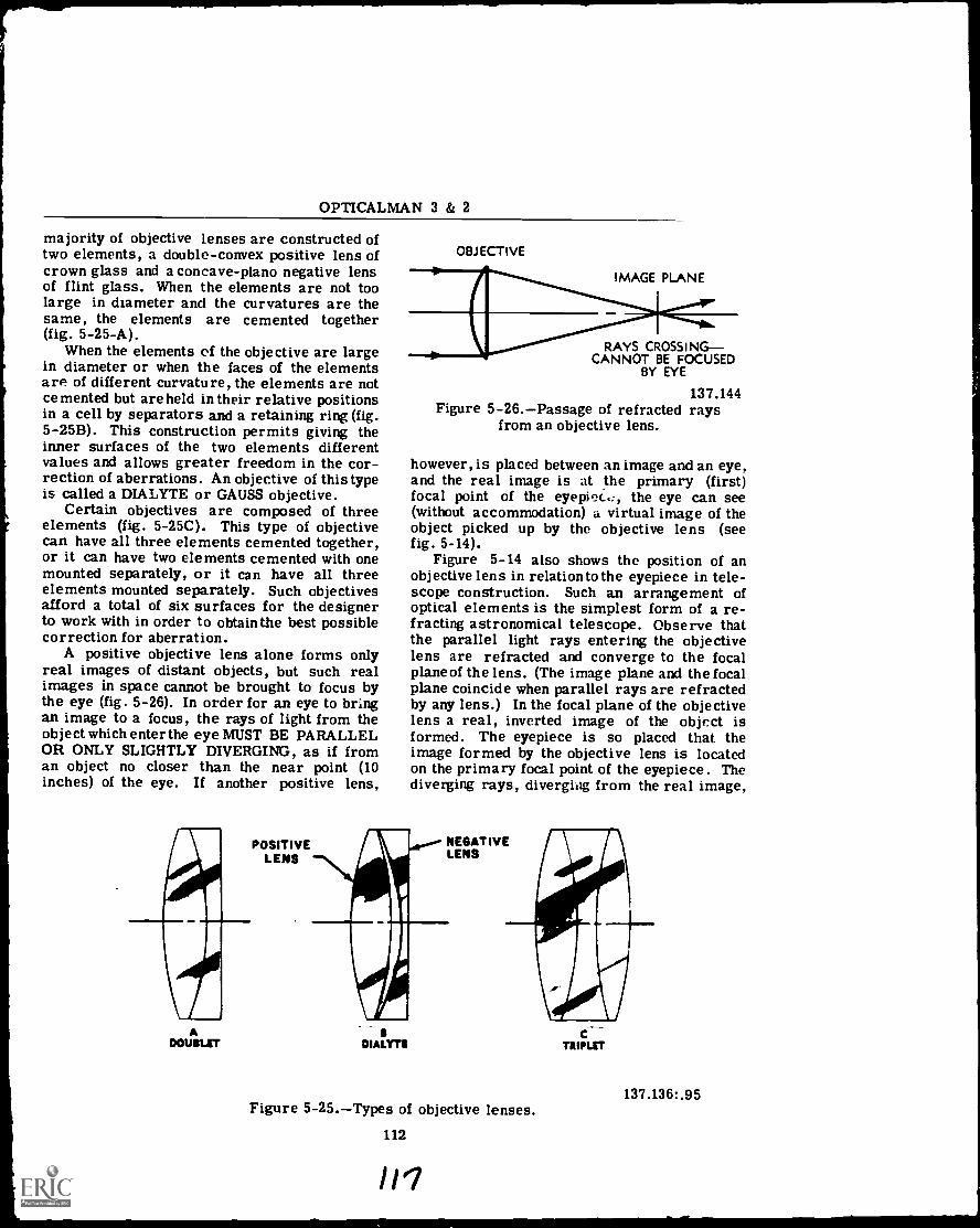
OPTICALMAN 3 & 2
majority of objective lenses are constructed oftwo elements, a double-convex positive lens ofcrown glass and a concave-plano negative lensof flint glass. When the elements are not toolarge in diameter and the curvatures are thesame, the elements are cemented together(fig. 5-25-A).
When the elements of the objective are largein diameter or when the faces of the elementsare of different curvature, the elements are notcemented but are held in their relative positionsin a cell by separators and a retaining ring (fig.5-25B). This construction permits giving theinner surfaces of the two elements differentvalues and allows greater freedom in the cor-rection of aberrations. An objective of this typeis called a DIALYTE or GAUSS objective.
Certain objectives are composed of threeelements (fig. 5-25C). This type of objectivecan have all three elements cemented together,or it can have two elements cemented with onemounted separately, or it can have all threeelements mounted separately. Such objectivesafford a total of six surfaces for the designerto work with in order to obtain the best possiblecorrection for aberration.
A positive objective lens alone forms onlyreal images of distant objects, but such realimages in space cannot be brought to focus bythe eye (fig. 5-26). In order for an eye to bringan image to a focus, the rays of light from theobject which enter the eye MUST BE PARALLELOR ONLY SLIGHTLY DIVERGING, as if froman object no closer than the near point (10inches) of the eye. If another positive lens,
ADOUBLET
POSITIVELENS
OBJECTIVE
IMAGE PLANE
RAYS CROSSINGCANNOT BE FOCUSED
BY EYE
137.144Figure 5-26.Passage of refracted rays
from an objective lens.
however, is placed between an image and an eye,and the real image is at the primary (first)focal point of the eyepiec.c, the eye can see(without accommodation) a virtual image of theobject picked up by the objective lens (seefig. 5-14).
Figure 5-14 also shows the position of anobjective lens in relation to the eyepiece in tele-scope construction. Such an arrangement ofoptical elements is the simplest form of a re-fracting astronomical telescope. Observe thatthe parallel light rays entering the objectivelens are refracted and converge to the focalplane of the lens. (The image plane and the focalplane coincide when parallel rays are refractedby any lens.) In the focal plane of the objectivelens a real, inverted image of the object isformed. The eyepiece is so placed that theimage formed by the objective lens is locatedon the primary focal point of the eyepiece. Thediverging rays, diverging from the real image,
NEGATIVELENS
IDIALYTE
Figure 5-25.Types of objective lenses.112
"7
137.136: .95
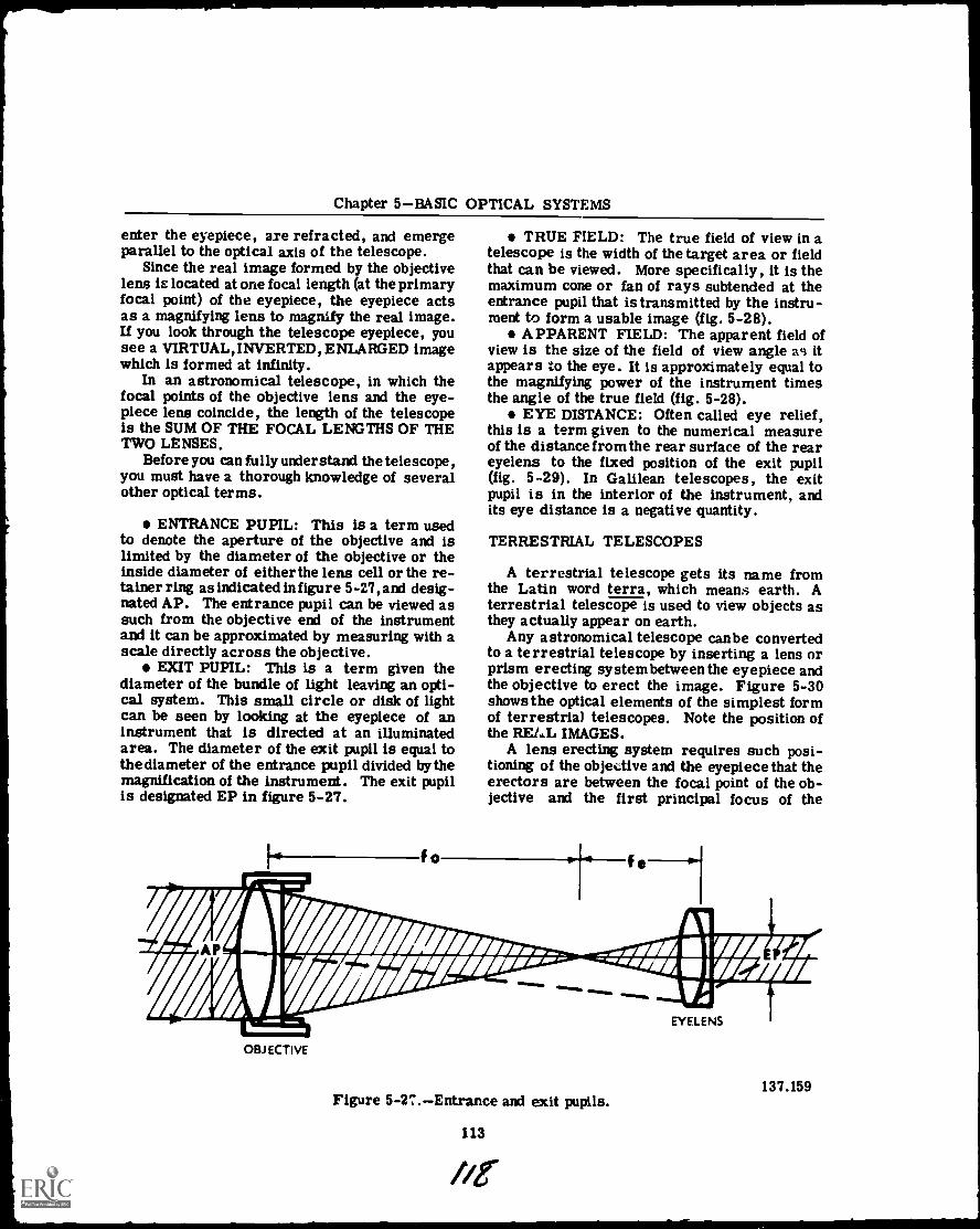
Chapter 5BASIC OPTICAL SYSTEMS
enter the eyepiece, are refracted, and emergeparallel to the optical axis of the telescope.
Since the real image formed by the objectivelens is located at one focal length (at the primaryfocal point) of the eyepiece, the eyepiece actsas a magnifying lens to magnify the real image.If you look through the telescope eyepiece, yousee a VIRTUAL,INVERTED, ENLARGED imagewhich is formed at infinity.
In an astronomical telescope, in which thefocal points of the objective lens and the eye-piece lens coincide, the length of the telescopeis the SUM OF THE FOCAL LENGTHS OF THETWO LENSES.
Before you can fully understand the telescope,you must have a thorough knowledge of severalother optical terms.
ENTRANCE PUPIL: This is a term usedto denote the aperture of the objective and islimited by the diameter of the objective or theinside diameter of either the lens cell or the re-tainer ring as indicated in figure 5 -27, and desig-nated AP. The entrance pupil can be viewed assuch from the objective end of the instrumentand it can be approximated by measuring with ascale directly across the objective.
EXIT PUPIL: This is a term given thediameter of the bundle of light leaving an opti-cal system. This small circle or disk of lightcan be seen by looking at the eyepiece of aninstrument that is directed at an illuminatedarea. The diameter of the exit pupil is equal tothe diameter of the entrance pupil divided by themagnification of the instrument. The exit pupilis designated EP in figure 5-27.
r.--=
01.707firiorff---/Armro
fo
TRUE FIELD: The true field of view in atelescope is the width of the target area or fieldthat can be viewed. More specifically, it is themaximum cone or fan of rays subtended at theentrance pupil that is transmitted by the instru-ment to form a usable image (fig. 5-28).
APPARENT FIELD: The apparent field ofview is the size of the field of view angle a9 itappears to the eye. It is approximately equal tothe magnifying power of the instrument timesthe angle of the true field (fig. 5-28).
EYE DISTANCE: Often called eye relief,this is a term given to the numerical measureof the distance fromthe rear surface of the reareyelens to the fixed position of the exit pupil(fig. 5-29). In Galilean telescopes, the exitpupil is in the interior of the instrument, andits eye distance is a negative quantity.
TERRESTRIAL TELESCOPES
A terrestrial telescope gets its name fromthe Latin word terra, which means earth. Aterrestrial telescope is used to view objects asthey actually appear on earth.
Any astronomical telescope canbe convertedto a terrestrial telescope by inserting a lens orprism erecting systembetweenthe eyepiece andthe objective to erect the image. Figure 5-30shows the optical elements of the simplest formof terrestrial telescopes. Note the position ofthe RE/ a, IMAGES.
A lens erecting system requires such posi-tioning of the objective and the eyepiece that theerectors are between the focal point of the ob-jective and the first principal focus of the
t f--1
OBJECTIVE
A'offal;
0/14111--'1 IM1rm'aAM/
Figure 5-27.Entrance and exit pupils.
113
EYELENS
137.159
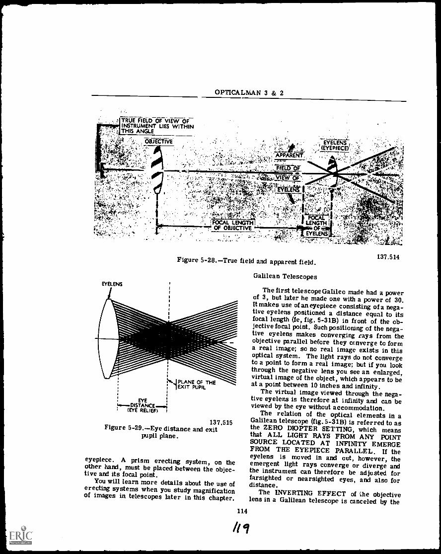
TRUE FIELD OF VIEW OFINSTRUMENT LIES WITHINTHIS ANGLE
137.515Figure 5-29.Eye distance and exit
pupil plane.
eyepiece. A prism erecting system, on theother hand, must be placed between the objec-tive and its focal point.
You will learn more details about the use oferecting systems when you study magnificationof images in telescopes later in this chapter.
Galilean Telescopes
The first telescopeGalileo made had a powerof 3, but later he made one with a power of 30.It makes use of an eyepiece consisting of a nega-tive eyelens positioned a distance equal to itsfocal length (fe, fig. 5-31B) in front of the ob-jective focal point. Such positioning of the nega-tive eyelens makes converging rays from theobjective parallel before they converge to forma real image; so no real image exists in thisoptical system. The light rays do not convergeto a point to form a real image; but if you lookthrough the negative lens you see an enlarged,virtual image of the object, which appears to beat a point between 10 inches and infinity.
The virtual image viewed through the nega-tive eyelens is therefore at infinity and can beviewed by the eye without accommodation.
The relation of the optical elements in aGalilean telescope (fig. 5-318) is referred to asthe ZERO DIOPTER SETTING, which meansthat ALL LIGHT RAYS FROM ANY POINTSOURCE LOCATED AT INFINITY EMERGEFROM THE EYEPIECE PARALLEL. If theeyelens is moved in and out, however, theemergent light rays converge or diverge andthe instrument can therefore be adjusted forfarsighted or nearsighted eyes, and also fordistance.
The INVERTING EFFECT of the objectivelens in a Galilean telescope is canceled by the

Chapter 5BASIC OPTICAL SYSTEMS
FIRST s
IMAGE PL.11NE,
Figure 5-30.The terrestrial telescope.
........._,..._,..
. A MI VIRTUAL
P
4 Ae AA V
OBJ ECT
N,OBJECTIVE/
EMERGENT RAYS
' 1 A
PARALLEL AT ZERODIOPTER SETTING(MINUS SETTING
ILLUSTRATED)
NEGATIVEEYELENS
137.516
I .0'4"/ A
OBJECTIVE
FOCAL POINT OF OBJECTIVE
EYELENS
f (OBJECTIVE)(EYELENSI
Figure 5-31.Galilean telescope.
negative eyelens, because the real image is notallowed to form; that is,the emergent rays fromthe negative eyepiece are refracted farther awayfrom the axis instead of recrossing it. The
115
137.150
virtual image of the object viewed is there-fore ERECT.
The principle of the Galilean system is dia-metrically opposite to that of the astronomical
/AO
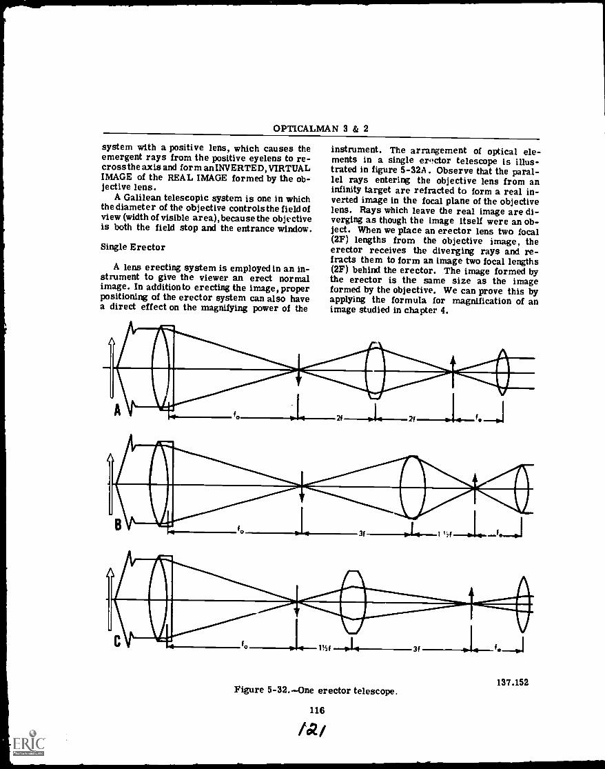
OPTICALMAN 3 & 2
system with a positive lens, which causes theemergent rays from the positive eyelens to re-cross the axis and form an INVERTED, VIRTUALIMAGE of the REAL IMAGE formed by the ob-jective lens.
A Galilean telescopic system is one in whichthe diameter of the objective controls the field ofview (width of visible area), because the objectiveis both the field stop and the entrance window.
Single Erector
A lens erecting system is employed in an in-strument to give the viewer an erect normalimage. In addition to erecting the image, properpositioning of the erector system can also havea direct effect on the magnifying power of the
instrument. The arrangement of optical ele-ments in a single erector telescope is illus-trated in figure 5-32A . Observe that the paral-lel rays entering the objective lens from aninfinity target are refracted to form a real in-verted image in the focal plane of the objectivelens. Rays which leave the real image are di-verging as though the image itself were an ob-ject. When we place an erector lens two focal(2F) lengths from the objective image, theerector receives the diverging rays and re-fracts them to form an image two focal lengths(2F) behind the erector. The image formed bythe erector is the same size as the imageformed by the objective. We can prove this byapplying the formula for magnification of animage studied in chapter 4.
4 3F 1 'if
137.152Figure 5-32.One erector telescope.
116
/a/
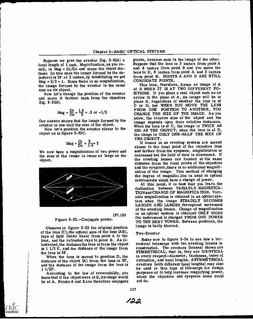
Chapter 5BASIC OPTICAL SYSTEMS
Suppose we give the erector (fig. 5-32A) afocal length of 1 inch. Magnification, as you re-call, is Mag = Di/Do and since the object dis-tance (in this case the image formed by the ob-jective) is 2F or 2 inches, by substituting we getMag = 2/2 = 1. Since there is no magnification,the image formed by the erector is the samesize as its object.
Now let's change the position of the erectorand move it further back from the objective(fig. 5-32B).
Di 1.5Mag To= = .5 or -1/2
Our answer shows that the image formed by theerector is one-half the size of the object.
Now let's position the erector closer to theobject as in figure 5-32C.
Di 3Mag ifo-o 2
We now have a magnification of two power andthe size of the image is twice as large as theobject.
137.153Figure 5-33.Conjugate points.
Observe in figure 5-33 the original positionof the lens (C), the optical axis of the lens (AB),rays of light (white lines) from point A to thelens, and the refracted rays to point B. As il-lustrated, the distance the lens is from the objectis 1 1/2 F, and the distance of the image fromthe lens is 3F.
When the lens is moved to position D, thedistance of the object (A) from the lens is 3F,and the distance of the image from the lens is1 1/2F.
According to the law of reversibility, youknow that if the object were at B, its image wouldbe at A. Points A and Bare therefore conjugate
points, because each is the image of the other.Suppose that the lens is 3 inches from point Aand 6 inches from point B and you move thelens to D, 6 inches from point A and 3 inchesfrom point B. POINTS A AND B ARE STILLCONJUGATE POINTS.
This lens, therefore, forms an image of Aat B WHEN IT IS AT TWO DIFFERENT PO-SITIONS. If you place a real object such as anarrow in the plane at A, its image will be inplane B, regardless of whether the lens is atC or D; but WHEN YOU MOVE THE LENSFROM ONE POSITION TO ANOTHER, YOUCHANGE THE SIZE OF THE IMAGE. As youknow, the relative size of the object and theimage depends upon their relative distances.When the lens is at C, the image is TWICE ASBIG AS THE OBJECT; when the lens is at D,the image is ONLY ONE-HALF THE SIZE OFTHE OBJECT.
If lenses in an erecting system are movedcloser to the focal point of the objective lensand farther from the eyepiece, magnification isincreased but the field of view is decreased. Ifthe erecting lenses are located at the samedistance from the focal points of the objectiveand the eyepiece,there is no additional magnifi-cation of the image. This method of changingthe degree of magnific2..Zion is used in opticalinstruments which have a change of power.
At this point, it is best that you learn thedistinction between VARIABLE MAGNIFICA-TIONand CHANGE OF MAGNIFICATION. Vari-able magnification is obtained in an optical sys-tem when the image STEADILY BECOMESLARGER AND LARGER throughout movementof the erecting lenses. Change of magnificationin an optical system is obtained ONLY WHENthe instrument is changed FROM ONE POWERTO THE NEXT POWER. Between positions, theimage is badly blurred.
117
Two-ErectorRefer now to figure 5-34 to see how a ter-
restrial telescope with two erecting lenses isconstructed. The erectors (lenses) shown areSYMMETRICAL; that is, they are IDENTICALin every respectdiameter, thickness, index ofrefraction, and focal lengths. ASYMMETRICALerectors (with different focal lengths) may alsobe used in this type of telescope for designpurposes or to help increase magnifying power,which the objective and eyepiece alone couldnot do.
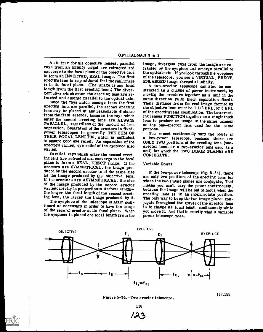
OPTICALMAN 3 & 2
As is true for all objective lenses, parallelrays from an infinity target are refracted andconverge to the focal plane of the objective lensto form an INVERTED, REAL image. The firsterecting lens is so positioned that the real imageis in its focal plane. (The image is one focallength from the first erecting lens.) The diver-gent rays which enter the erecting lens are re-fracted and emerge parallel to the optical axis.
Since the rays which emerge from the first'erecting lens are parallel, the second erectinglens may be placed at any reasonable distancefrom the first erector, because the rays whichenter the second erecting lens are ALWAYSPARALLEL, regardless of the amount of lensseparation. Separation of the erectors in fixed-power telescopes is generally THE SUM OFTHEIR FOCAL LENGTHS, which is sufficientto ensure good eye relief. As separation of theerectors varies, eye relief of the eyepiece alsovaries.
Parallel rays which enter the second erect-ing lens are refracted and converge to the focalplane to form a REAL, ERECT image. If theerectors are SYMMETRICAL, the image pro-duced by the second erector is of the same sizeas the image produced by the objective lens.If the erectors are ASYMMETRICAL, the sizeof the image produced by the second erectorvaries directly in proportionto its foca: engththe longer the focal length of the second erect-ing lens, the larger the image produced by it.
The eyepiece of the telescope is again posi-tioned as necessary in order. to have the imageof the second erector at its focal plane. Whenthe eyepiece is placed one focal length from the
OBJECTIVEE
image, divergent rays from the image are re-fracted by the eyepiece and emerge parallel tothe optical axis. If you look through the eyepieceof the telescope, you see a VIRTUAL, ERECT,ENLARGED image formed at infinity.
A two-erector telescope can also be con-structed as a change of power instrument, bymoving the erectors together as a unit in thesame direction (with their separation fixed).Their distance from the real image formed bythe objective lens must be 1 1/2 EFL, or 3 EFLof the erecting lens combination. The two erect-ing lenses FUNCTION together as a single thicklens to produce an image in the same manneras the one-erector lens used for the samepurpose.
You cannot continuously vary the power ina two-power telescope, because there areONLY TWO positions of the erecting lens (one-erector lens, or a two-erector lens used as aunit) for which the TWO IMAGE PLANES ARECONJUGATE .
Variable Power
In the two-power telescope (fig. 5-34), thereare only two positions of the erecting lens forwhich the two image planes are conjugate, Thatmeans you can't vary the power continuously,because the image will be out of focus when theerecting lens is in an intermediate position.The only way to keep the two image planes con-jugate throughout the travel of the erector lensis to change its focal length continuously whileyou move it. And that is exactly what a variablepower telescope does.
ERECTORS
E2 EYEPIECE
E
f =1E2
fE2-44-f
137.155Figure 5-34.Two erector telescope.
118
fat
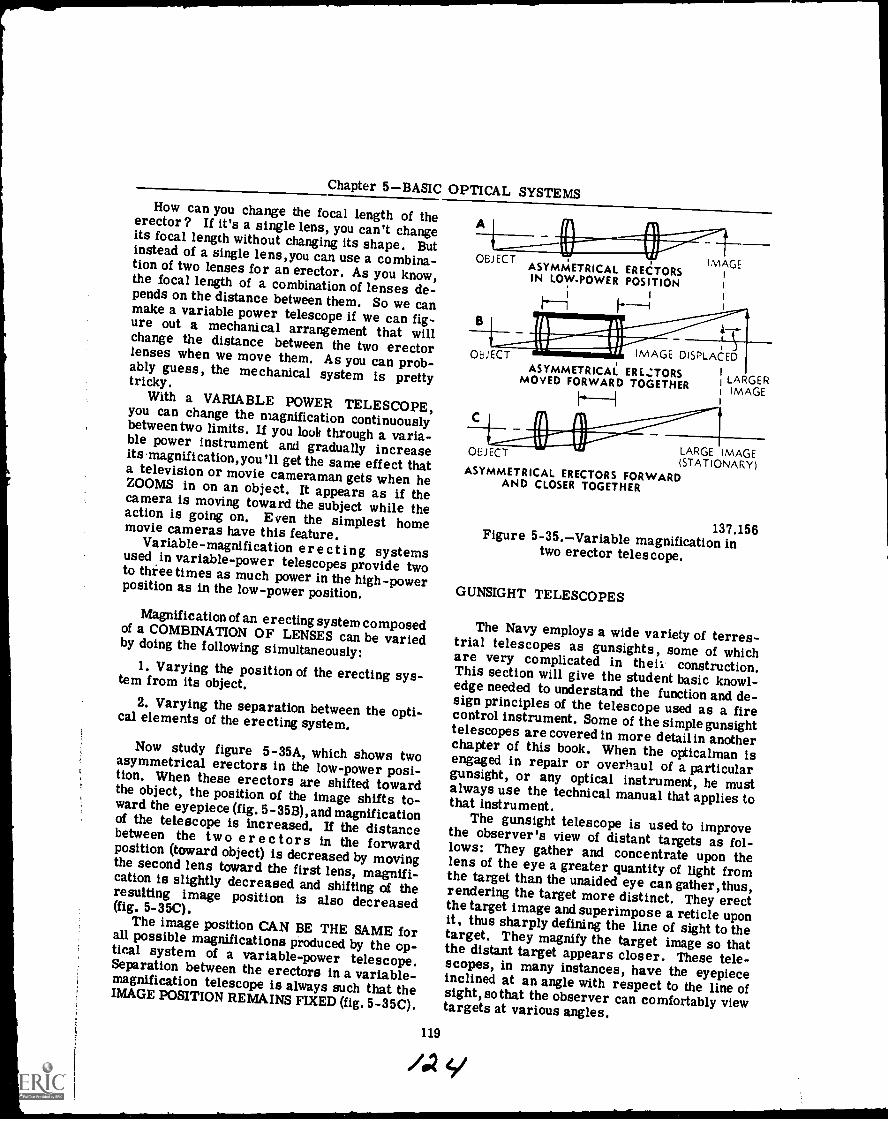
Chapter 5BASIC OPTICAL SYSTEMSHow can you change the focal length of theerector? If it's a single lens, you can't changeits focal length without changing its shape. Butinstead of a single lens,you can use a combina-tion of two lenses for an erector. As you know,the focal length of a combination of lenses de-pends on the distance between them. So we canmake a variable power telescope if we can fig-ure out a mechanical arrangement that willchange the distance between the two erectorlenses when we move them. As you can prob-ably guess, the mechanical system is prettytricky.
With a VARIABLE POWER TELESCOPE,you can change the magnification continuouslybetween two limits. If you look through a varia-ble power instrument and gradually increaseits .magnification,you '11 get the same effect thata television or movie cameraman gets when heZOOMS in on an object. It appears as if thecamera is moving toward the subject while theaction is going on. Even the simplest homemovie cameras have this feature.Variable-magnification erecting systemsused .in variable-power telescopes provide twoto three times as much power in the high-powerposition as in the low-power position.
Magnification of an erecting system composedof a COMBINATION OF LENSES can be variedby doing the following simultaneously:1. Varying the position of the erecting sys-tem from its object.
2. Varying the separation between the opti-cal elements of the erecting system.
Now study figure 5-35A, which shows twoasymmetrical erectors in the low-power posi-tion. When these erectors are shifted towardthe object, the position of the image shifts to-ward the eyepiece (fig. 5 -35B), and magnificationof the telescope is increased. If the distancebetween the two e r e c tor s in the forwardposition (toward object) is decreased by movingthe second lens toward the first lens, magnifi-cation is slightly decreased and shifting of theresulting image position is also decreased(fig. 5-35C).The image position CAN BE THE SAME forall possible magnifications produced by the op-tical system of a variable-power telescope.Separation between the erectors in a variable-magnification telescope is always such that theIMAGE POSITION REMAINS FIXED (fig. 5-35C).
OBJECTASYMMETRICAL ERECTORSIN LOW-POWER POSITION
; I
B11111111.1111us
VI P'IV f1 IMAGE DISPLACED
IMAGE
OBJECT
ASYMMETRICAL ERECTORSMOVED FORWARD TOGETHER LARGER
IMAGE
LARGE IMAGE(STATIONARY)
ASYMMETRICAL ERECTORS FORWARDAND CLOSER TOGETHER
137.156Figure 5-35.Variable magnification intwo erector telescope.
GUNSIGHT TELESCOPES
The Navy employs a wide variety of terres-trial telescopes as gunsights, some of whichare very complicated in their construction.This section will give the student basic knowl-edge needed to understand the function and de-sign principles of the telescope used as a firecontrol instrument. Some of the simplegunsighttelescopes are covered in more detail in anotherchapter of this book. When the opticalman isengaged in repair or overhaul of a particulargunsight, or any optical instrument, he mustalways use the technical manual that applies tothat instrument.The gunsight telescope is used to improvethe observer's view of distant targets as fol-lows: They gather and concentrate upon thelens of the eye a greater quantity of light fromthe target than the unaided eye can gather, thus,rendering the target more distinct. They erectthe target image and superimpose a reticle uponit, thus sharply defining the line of sight to thetarget. They magnify the target image so thatthe distant target appears closer. These tele-scopes, in many instances, have the eyepieceinclined at an angle with respect to the line ofsight, so that the observer can comfortably viewtargets at various angles.
119
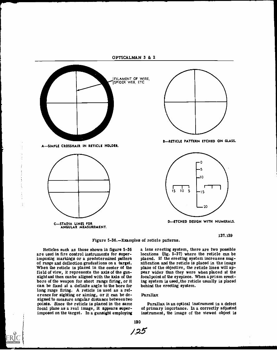
OPTICALMAN 3 & 2
FILAMENT OF WIRE,SPIDER WEB, ETC.
A-SIMPLE CROSSHAIR IN RETICLE HOLDER.
C-STADIA LINES FORANGULAR MEASUREMENT.
B-RETICLE PATTERN ETCHED ON GLASS.
D-ETCHED DESIGN WITH NUMERALS.
Figure 5-36.Examples of reticle patterns.
Reticles such as those shown in figure 5-36are used in fire control instruments for super-imposing markings or a predetermined patternof range and deflection graduations on a target.When the reticle is placed in the center of thefield of view, it represents the axis of the gun-sight and then can be aligned with the axis of thebore of the weapon for short range firing, or itcan be fixed at a definite angle to the bore forlong range firing. A reticle is used as a ref-erence for sighting or aiming, or it can be de-signed to measure angular distance between twopoints. Since the reticle is placed in the samefocal plane as a real image, it appears super-imposed on the target. In a gunsight employing
137.139
a lens erecting system, there are two possiblelocations (fig. 5-37) where the reticle can beplaced. If the erecting system increases mag-nification and the reticle is placed in the imageplane of the objective, the reticle lines will ap-pear wider than they were when placed at thefocalpoint of the eyepiece. When a prism erect-ing system is used,the reticle usually is placedbehind the erecting system.
120
Parallax
Parallax in an optical instrument is a defectof primary importance. In a correctly adjustedinstrument, the image of the viewed object is
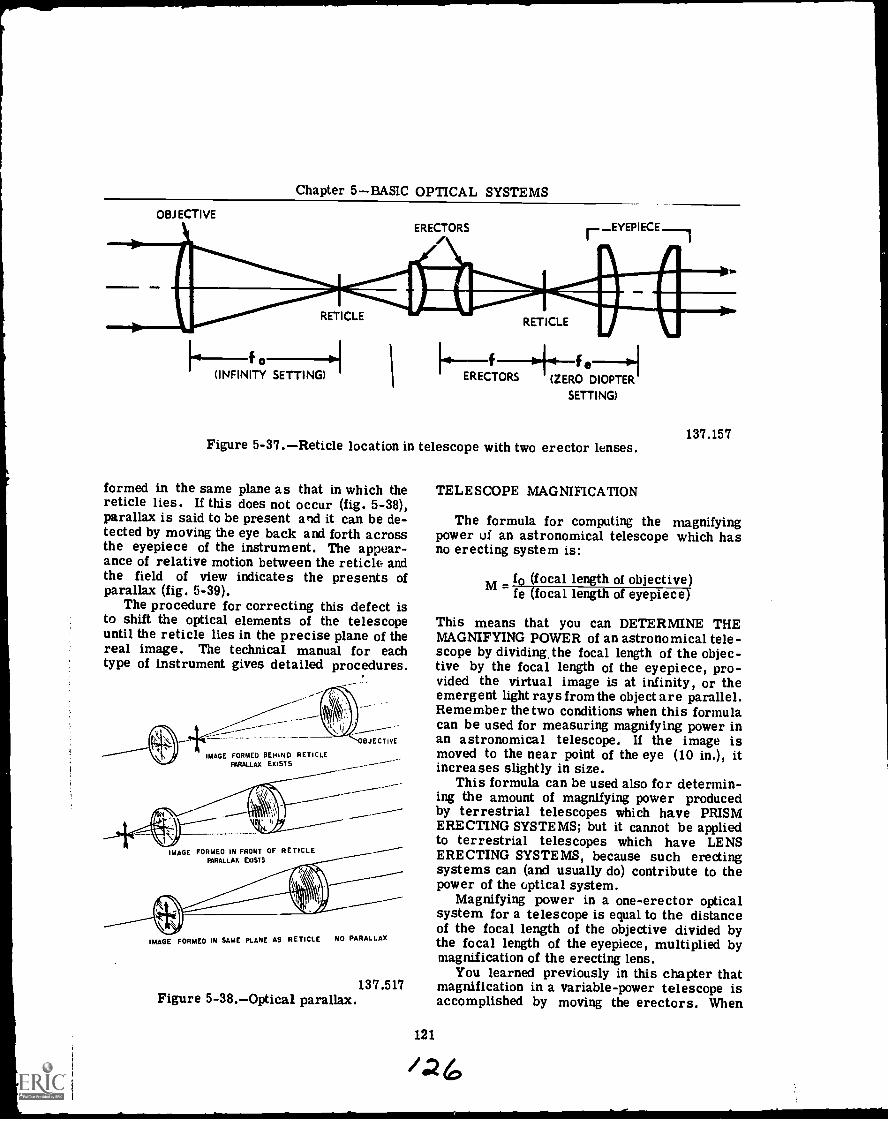
Chapter 5BASIC OPTICAL SYSTEMS
OBJECTIVEERECTORS -EYEPIECE
RETICLE-1/1141 Aid
RETICLE
101---f0-01(INFINITY SETTING)
fERECTORS
fe(ZERO DIOPTER
SETTING)
Figure 5-37.Reticle location in telescope with two erector lenses.
formed in the same plane as that in which thereticle lies. If this does not occur (fig. 5-38),parallax is said to be present and it can be de-tected by moving the eye back and forth acrossthe eyepiece of the instrument. The appear-ance of relative motion between the reticle andthe field of view indicates the presents ofparallax (fig. 5-39).
The procedure for correcting this defect isto shift the optical elements of the telescopeuntil the reticle lies in the precise plane of thereal image. The technical manual for eachtype of instrument gives detailed procedures.
IMAGE FORMED BEMINO RETICLEFARALLAX EXISTS
BJECTIVE
IMAGE FORMED IN FRONT OF RETICLEPARALLAX EXISTS
IMAGE FORMED IN SAME PLANE AS RETICLE NO PARALLAX
Figure 5-38.Optical parallax.137.517
TELESCOPE MAGNIFICATION
137.157
The formula for computing the magnifyingpower of an astronomical telescope which hasno erecting system is:
M - fo (focal length of objective)fe (focal length of eyepiece)
This means that you can DETERMINE THEMAGNIFYING POWER of an astronomical tele-scope by dividing, the focal length of the objec-tive by the focal length of the eyepiece, pro-vided the virtual image is at infinity, or theemergent light rays from the object are parallel.Remember the two conditions when this formulacan be used for measuring magnifying power inan astronomical telescope. If the image ismoved to the near point of the eye (10 in.), itincreases slightly in size.
This formula can be used also for determin-ing the amount of magnifying power producedby terrestrial telescopes which have PRISMERECTING SYSTEMS; but it cannot be appliedto terrestrial telescopes which have LENSERECTING SYSTEMS, because such erectingsystems can (and usually do) contribute to thepower of the optical system.
Magnifying power in a one-erector opticalsystem for a telescope is equal to the distanceof the focal length of the objective divided bythe focal length of the eyepiece, multiplied bymagnification of the erecting lens.
You learned previously in this chapter thatmagnification in a variable-power telescope isaccomplished by moving the erectors. When
121
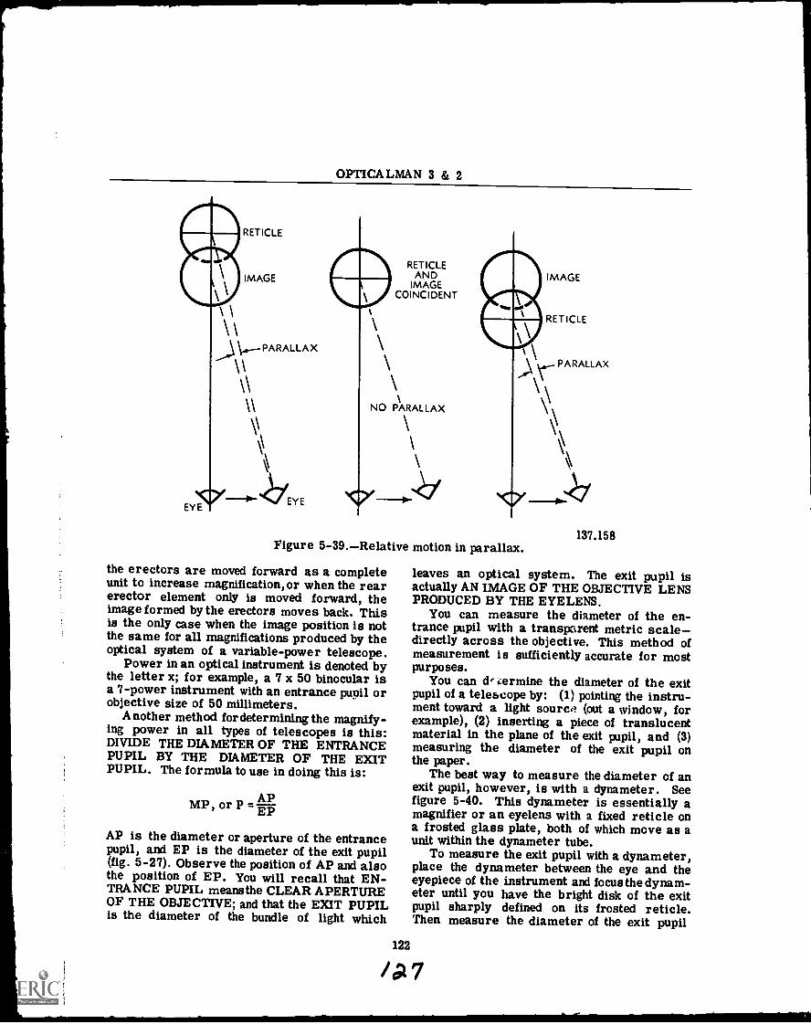
OPTICALMAN 3 & 2
RETICLE
IMAGERETICLE
ANDIMAGE
COINCIDENT
PARALLAX
\\
AllerrEYE
NO PARALLAX
.1=111,
PARALLAX
7
IMAGE
RET ICLE
Figure 5-39.Relative motion in parallax.
the erectors are moved forward as a completeunit to increase magnification, or when the rearerector element only is moved forward, theimage formed by the erectors moves back. Thisis the only case when the image position is notthe same for all magnifications produced by theoptical system of a variable-power telescope.
Power in an optical instrument is denoted bythe letter x; for example, a 7 x 50 binocular isa 7-power instrument with an entrance pupil orobjective size of 50 millimeters.
Another method for determining the magnify-ing power in all types of telescopes is this:DIVIDE THE DIAMETER OF THE ENTRANCEPUPIL BY THE DIAMETER OF THE EXITPUPIL. The formula to use in doing this is:
APMP, or P
AP is the diameter or aperture of the entrancepupil, and EP is the diameter of the exit pupil(fig. 5-27). Observe the position of AP and alsothe position of EP. You will recall that EN-TRANCE PUPIL meansthe CLEAR APERTUREOF THE OBJECTIVE; and that the EXIT PUPILis the diameter of the bundle of light which
137.158
leaves an optical system. The exit pupil isactually AN IMAGE OF THE OBJECTIVE LENSPRODUCED BY THE EYELENS.
You can measure the diameter of the en-trance pupil with a transparent metric scaledirectly across the objective. This method ofmeasurement is sufficiently accurate for mostpurposes.
You can de ermine the diameter of the exitpupil of a telescope by: (1) pointing the instru-ment toward a light sourc,? (out a window, forexample), (2) inserting a piece of translucentmaterial in the plane of the exit pupil, and (3)measuring the diameter of the exit pupil onthe paper.
The best way to measure the diameter of anexit pupil, however, is with a dynameter. Seefigure 5-40. This dynameter is essentially amagnifier or an eyelens with a fixed reticle ona frosted glass plate, both of which move as aunit within the dynameter tube.
To measure the exit pupil with a dynameter,place the dynameter between the eye and theeyepiece of the instrument and focus the dynam-eter until you have the bright disk of the exitpupil sharply defined on its frosted reticle.Then measure the diameter of the exit pupil
122
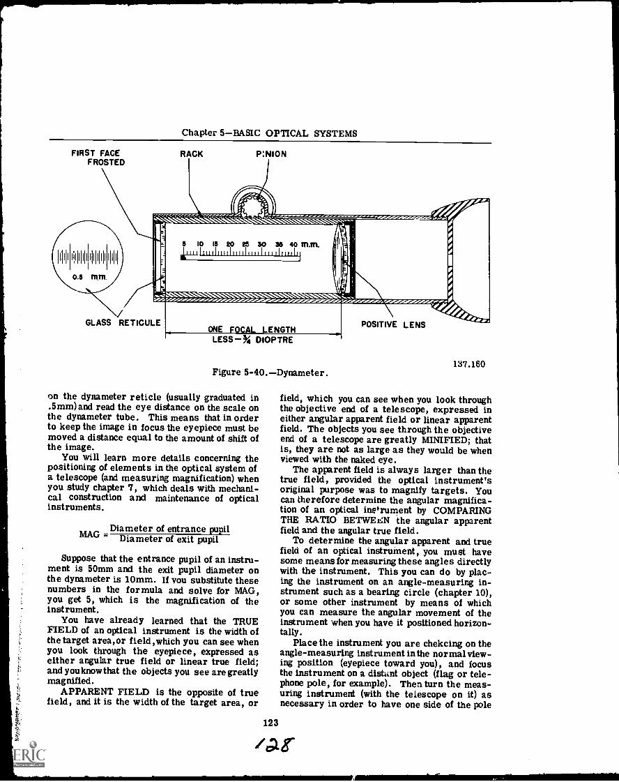
Chapter 5BASIC OPTICAL SYSTEMS
FIRST FACEFROSTED
RACK PINION
5 10 15 20 26 30 36 40 MM.
PA
rj
y,- ' ` ." ":' ."'\ -oli /Cr Cr'
GLASS RETICULEONE FOCAL LENGTHLESS% DIOPTRE
Figure 5-40.Dynameter.
on the dynameter reticle (usually graduated in.5mm) and read the eye distance on the scale onthe dynameter tube. This means that in orderto keep the image in focus the eyepiece must bemoved a distance equal to the amount of shift ofthe image.
You will learn more details concerning thepositioning of elements in the optical system ofa telescope (and measuring magnification) whenyou study chapter 7, which deals with mechani-cal construction and maintenance of opticalinstruments.
Diameter of entrance pupilMAG Diameter of exit pupil
Suppose that the entrance pupil of an instru-ment is 50mm and the exit pupil diameter onthe dynameter is 10mm. If you substitute thesenumbers in the formula and solve for MAG,you get 5, which is the magnification of theinstrument.
You have already learned that the TRUEFIELD of an optical instrument is the width ofthe target area,or field ,which you can see whenyou look through the eyepiece, expressed aseither angular true field or linear true field;and you knowthat the objects you see are greatlymagnified.
APPARENT FIELD is the opposite of truefield, and it is the width of the target area, or
POSITIVE LENS
137.160
field, which you can see when you look throughthe objective end of a telescope, expressed ineither angular apparent field or linear apparentfield. The objects you see through the objectiveend of a telescope are greatly MINIFIED; thatis, they are not as large as they would be whenviewed with the naked eye.
The apparent field is always larger than thetrue field, provided the optical instrument'soriginal purpose was to magnify targets. Youcan therefore determine the angular magnifica-tion of an optical inerument by COMPARINGTHE RATIO BETWEEN the angular apparentfield and the angular true field.
To determine the angular apparent and truefield of an optical instrument, you must havesome means for measuring these angles directlywith the instrument. This you can do by plac-ing the instrument on an angle-measuring in-strument such as a bearing circle (chapter 10),or some other instrument by means of whichyou can measure the angular movement of theinstrument when you have it positioned horizon-tally.
Place the instrument you are chekcing on theangle-measuring instrument in the normal view-ing position (eyepiece toward you), and focusthe instrument on a distant object (flag or tele-phone pole, for example). Then turn the meas-uring instrument (with the telescope on it) asnecessary in order to have one side of the pole
123
/At
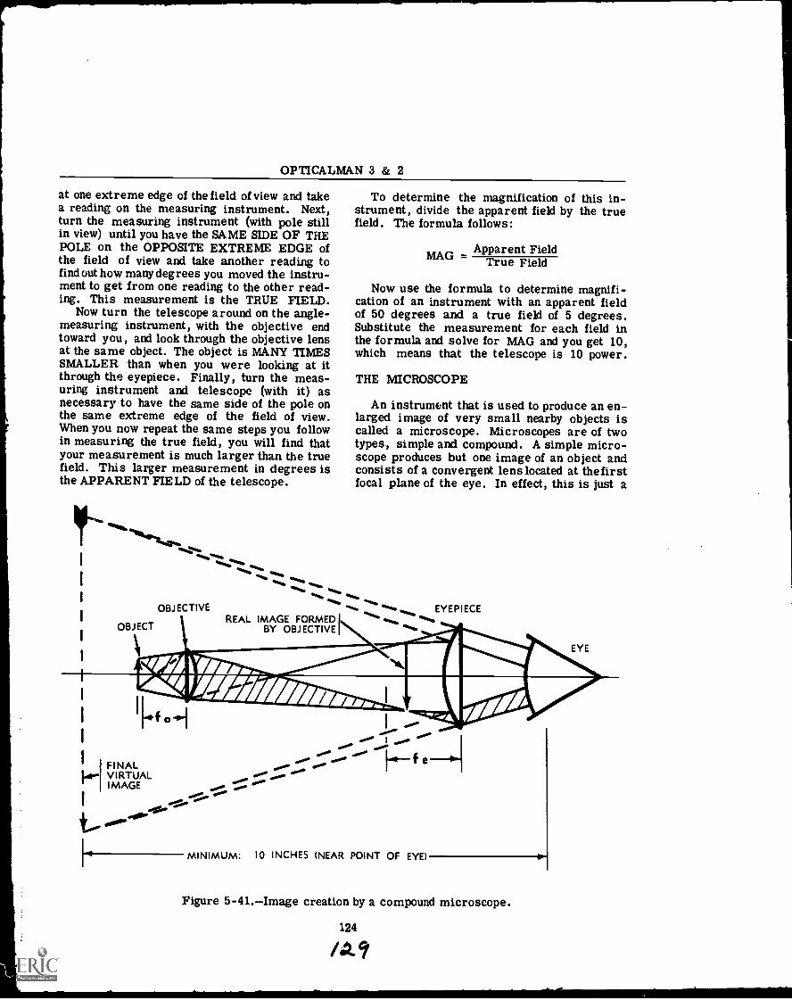
OPTICALMAN 3 & 2
at one extreme edge of the field of view and takea reading on the measuring instrument. Next,turn the measuring instrument (with pole stillin view) until you have the SAME SIDE OF THEPOLE on the OPPOSITE EXTREME EDGE ofthe field of view and take another reading tofind out how many degrees you moved the instru-ment to get from one reading to the other read-ing. This measurement is the TRUE FIELD.
Now turn the telescope around on the angle-measuring instrument, with the objective endtoward you, and look through the objective lensat the same object. The object is MANY TIMESSMALLER than when you were looking at itthrough the eyepiece. Finally, turn the meas-uring instrument and telescope (with it) asnecessary to have the same side of the pole onthe same extreme edge of the field of view.When you now repeat the same steps you followin measuring the true field, you will find thatyour measurement is much larger than the truefield. This larger measurement in degrees isthe APPARENT FIELD of the telescope.
MIN
441k04.0....
ft111:11.111.
..11%
OBJECTIVE
OBJECTREAL IMAGE FORMED I
BY OBJECTIVE
FINAL1.4.- VIRTUAL
IMAGE
To determine the magnification of this in-strument, divide the apparent field by the truefield. The formula follows:
Apparent FieldMAG = True Field
Now use the formula to determine magnifi-cation of an instrument with an apparent fieldof 50 degrees and a true field of 5 degrees.Substitute the measurement for each field inthe formula and solve for MAG and you get 10,which means that the telescope is 10 power.
THE MICROSCOPE
An instrument that is used to produce an en-larged image of very small nearby objects iscalled a microscope. Microscopes are of twotypes, simple and compound. A simple micro-scope produces but one image of an object andconsists of a convergent lens located at thefirstfocal plane of the eye. In effect, this is just a
EYEPIECE
EYE
**gta-
py
.00.AlPII
.f e
MINIMUM: 10 INCHES (NEAR POINT OF EYE)
Figure 5-41.Image creation by a compound microscope.
Chapter 5BASIC OPTICAL SYSTEMS
simple magnifying lens as covered in chapter 4.A compound microscope first forms an imageby the objective lens, and this primary imageis further magnified by an eyepiece.
You perhaps used a compound microscope tolook at minute plants and animals whenyou werein high school. Such an optical instrument somagnifies small objects that it increases theusefulness of the eyes at short distances. Theeyes, by nature, are long-range optical instru-ments of high acuity.
Refer now to figure 5-41, which shows one ofthe simplest types of compound microscopes.Study all details and the nomenclature. Notethe position of the eye, the eyepiece, the ob-jective, and the object. Then observe the posi-tions of the real and virtual images.
Rays of light from the object strike the ob-jective (closest lens to the object) and thenstrike the eyepiece, which refracts them in thedirection of the eye. The objective of a micro-scope has an extremely short focal length, toensure enlargement of the image formed onthe retinas of the eyes. The image it forms is
real, enlarged, and inverted, as shown. THEEXTREMELY SHORT FOCAL LENGTH OFTHE OBJECTIVE IS REPRESENTED BY fo; theSHORT FOCAL LENGTH OF THE CONVERG-ING EYEPIECE IS REPRESENTED BY fe.
If the real image is at the first principal focusof the eyelens,the eyes seethe image at infinityand no accommodation is necessary. The final,virtual image (large, broken arrow) may beformed at any distance which exceeds the short-est distance of distinct vision (about 10 inches).In this case, the image formed by the objectivemust be within the principal focus of the eye-piece, fe (fig. 5-41). Magnification in a micro-scope depends upon the focal lengths of theobjective and the eyepiece, and the distance be-tween these two optical elements. A compoundmicroscope can magnify an object about 2,000times (diameters); but little increase, if any, inthe details of an object is obtained after the ob-ject has been magnified 400 times. Magnifyingpower of a compound microscope is equal to themagnification of the objective lens multiplied bythe magnifying power of the eyepiece.
125
/36
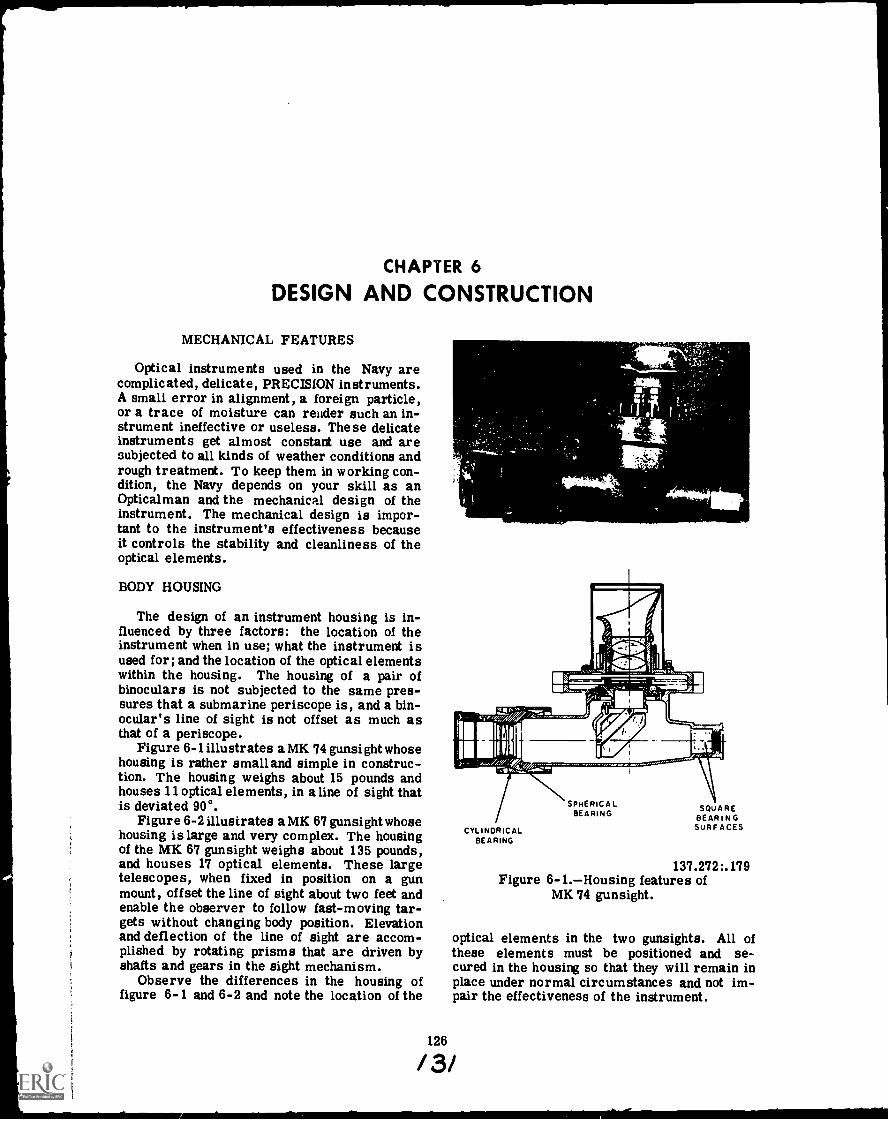
CHAPTER 6
DESIGN AND CONSTRUCTION
MECHANICAL FEATURES
Optical instruments used in the Navy arecomplicated, delicate, PRECISION instruments.A small error in alignment, a foreign particle,or a trace of moisture can resider such an in-strument ineffective or useless. These delicateinstruments get almost constant use and aresubjected to all kinds of weather conditions andrough treatment. To keep them in working con-dition, the Navy depends on your skill as anOpticalman and the mechanical design of theinstrument. The mechanical design is impor-tant to the instrument's effectiveness becauseit controls the stability and cleanliness of theoptical elements.
BODY HOUSING
The design of an instrument housing is in-fluenced by three factors: the location of theinstrument when in use; what the instrument isused for; and the location of the optical elementswithin the housing. The housing of a pair ofbinoculars is not subjected to the same pres-sures that a submarine periscope is, and a bin-ocular's line of sight is not offset as much asthat of a periscope.
Figure 6-1 illustrates a MK 74 gunsight whosehousing is rather small and simple in construc-tion. The housing weighs about 15 pounds andhouses 11 optical elements, in aline of sight thatis deviated 90°.
Figure 6-2 illustrates a MK 67 gunsight whosehousing is large and very complex. The housingof the MK 67 gunsight weighs about 135 pounds,and houses 17 optical elements. These largetelescopes, when fixed in position on a gunmount, offset the line of sight about two feet andenable the observer to follow fast-moving tar-gets without changing body position. Elevationand deflection of the line of sight are accom-plished by rotating prisms that are driven byshafts and gears in the sight mechanism.
Observe the differences in the housing offigure 6-1 and 6-2 and note the location of the
CYLINDRICALBEARING
SPHERICALBEARING SQUARE
BEARINGSURFACES
137.272:.179Figure 6-1.--Housing features of
MK 74 gunsight.
optical elements in the two gunsights. All ofthese elements must be positioned and se-cured in the housing so that they will remain inplace under normal circumstances and not im-pair the effectiveness of the instrument.
126
/3/
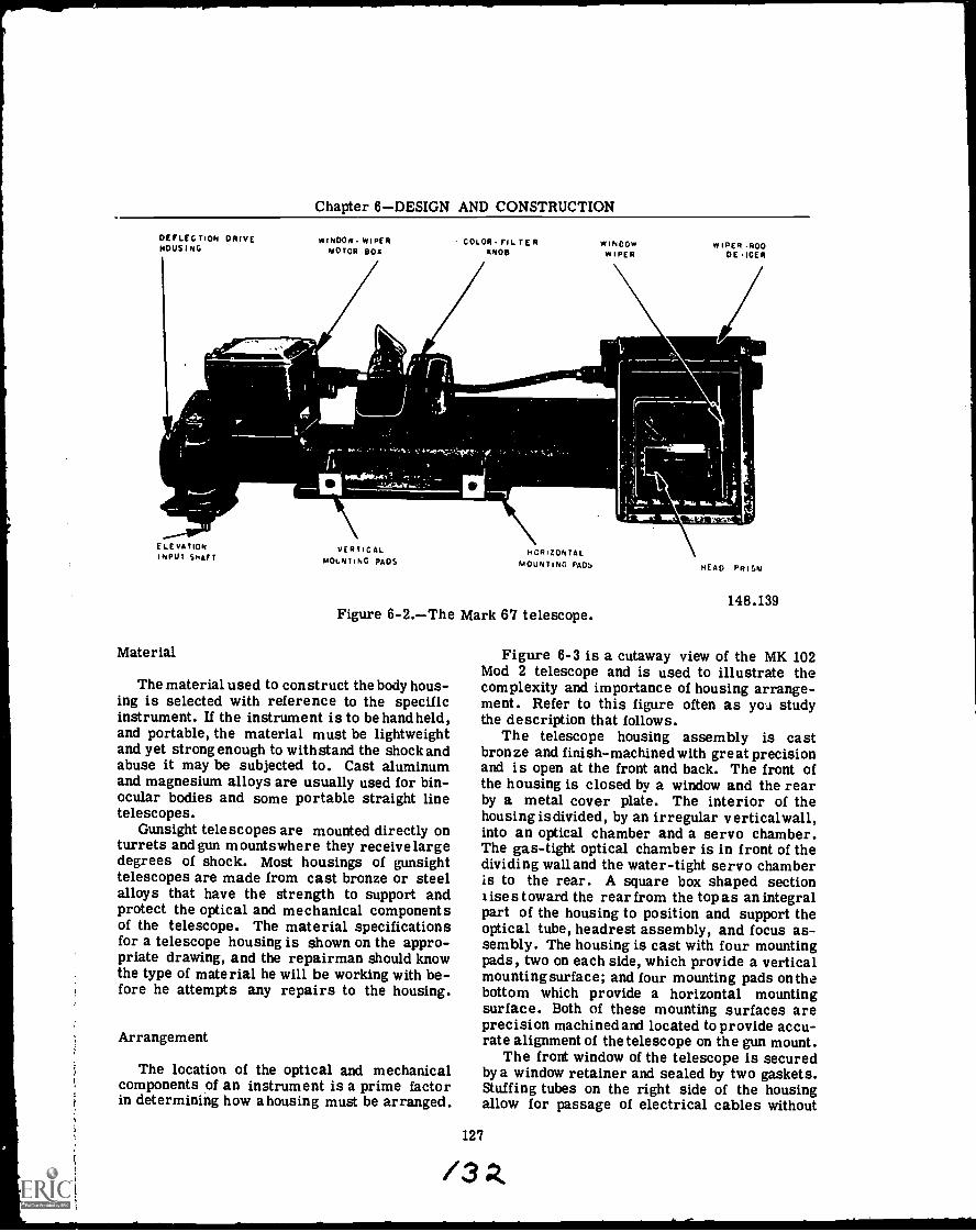
Chapter 6DESIGN AND CONSTRUCTION
DEFLECTION DRIVEHOUSING
WINDOW WIPERMOTOR BOX
COLOR FIL TERKNOB
WINDOWWIPER
WIPER -ROODE ICER
E LE VATIONINPUT SHAFT
Material
VERTICALMOUNTING PADS
HORIZONTALMOUNTING PADS
Figure 6-2.The Mark 67 telescope.
The material used to construct the body hous-ing is selected with reference to the specificinstrument. If the instrument is to be handheld,and portable, the material must be lightweightand yet strong enough to withstand the shock andabuse it may be subjected to. Cast aluminumand magnesium alloys are usually used for bin-ocular bodies and some portable straight linetelescopes.
Gunsight telescopes are mounted directly onturrets and gun mountswhere they receive largedegrees of shock. Most housings of gunsighttelescopes are made from cast bronze or steelalloys that have the strength to support andprotect the optical and mechanical componentsof the telescope. The material specificationsfor a telescope housing is shown on the appro-priate drawing, and the repairman should knowthe type of material he will be working with be-fore he attempts any repairs to the housing.
Arrangement
The location of the optical and mechanicalcomponents of an instrument is a prime factorin determining how a housing must be arranged.
HEAD PRISM
148.139
Figure 6-3 is a cutaway view of the MK 102Mod 2 telescope and is used to illustrate thecomplexity and importance of housing arrange-ment. Refer to this figure often as you studythe description that follows.
The telescope housing assembly is castbronze and finish-machined with great precisionand is open at the front and back. The front ofthe housing is closed by a window and the rearby a metal cover plate. The interior of thehousing isdivided, by an irregular verticalwall,into an optical chamber and a servo chamber.The gas-tight optical chamber is in front of thedividing wall and the water-tight servo chamberis to the rear. A square box shaped sectionises toward the rear from the top as an integral
part of the housing to position and support theoptical tube, headrest assembly, and focus as-sembly. The housing is cast with four mountingpads, two on each side, which provide a verticalmounting surface; and four mounting pads on thebottom which provide a horizontal mountingsurface. Both of these mounting surfaces areprecision machined and located to provide accu-rate alignment of the telescope on the gun mount.
The front window of the telescope is securedby a window retainer and sealed by two gaskets.Stuffing tubes on the right side of the housingallow for passage of electrical cables without
127
/3
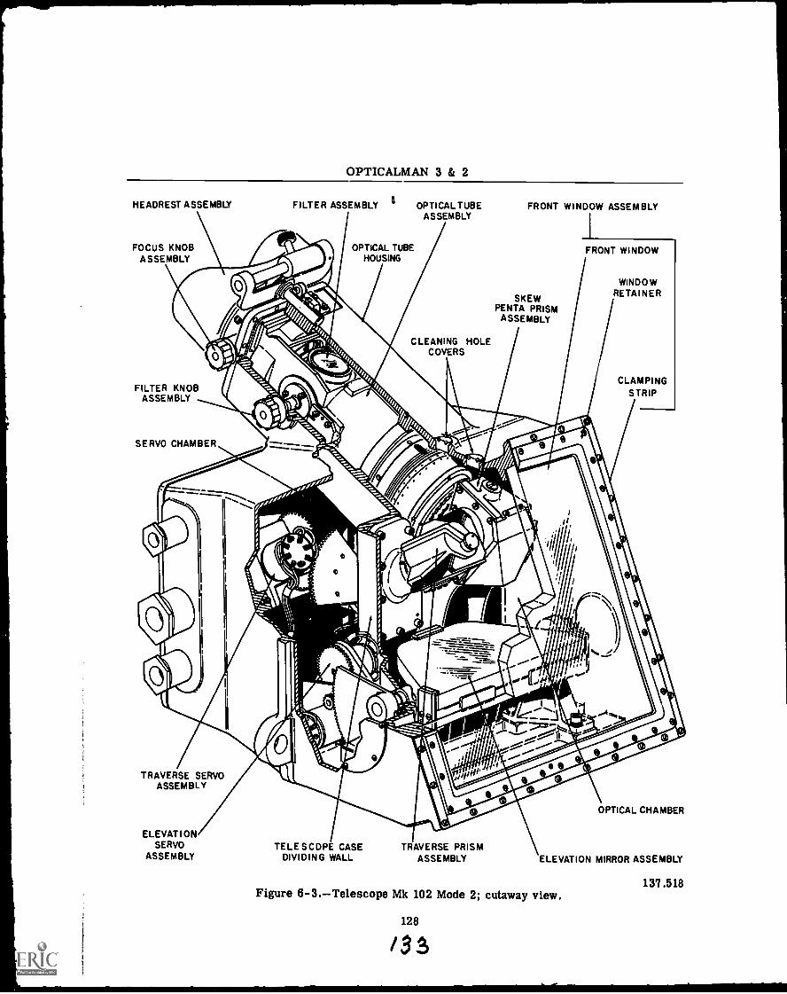
OPTICALMAN 3 & 2
HEADREST ASSEMBLY
FOCUS KNOBASSEMBLY
FILTER ASSEMBLY OPTICAL TUBEASSEMBLY
OPTICAL TUBEHOUSING
FRONT WINDOW ASSEMBLY
SKEWPENTA PRISM
ASSEMBLY
CLEANING HOLECOVERS
FILTER KNOBASSEMBLY
SERVO CHAMBER
TRAVERSE SERVOASSEMBLY
ELEVATIONSERVO TELESCOPE CASE TRAVERSE PRISM
ASSEMBLY DIVIDING WALL ASSEMBLY ELEVATION MIRROR ASSEMBLY
OPTICAL CHAMBER
137.518Figure 6-3.Telescope Mk 102 Mode 2; cutaway view.
128
/ 3 S
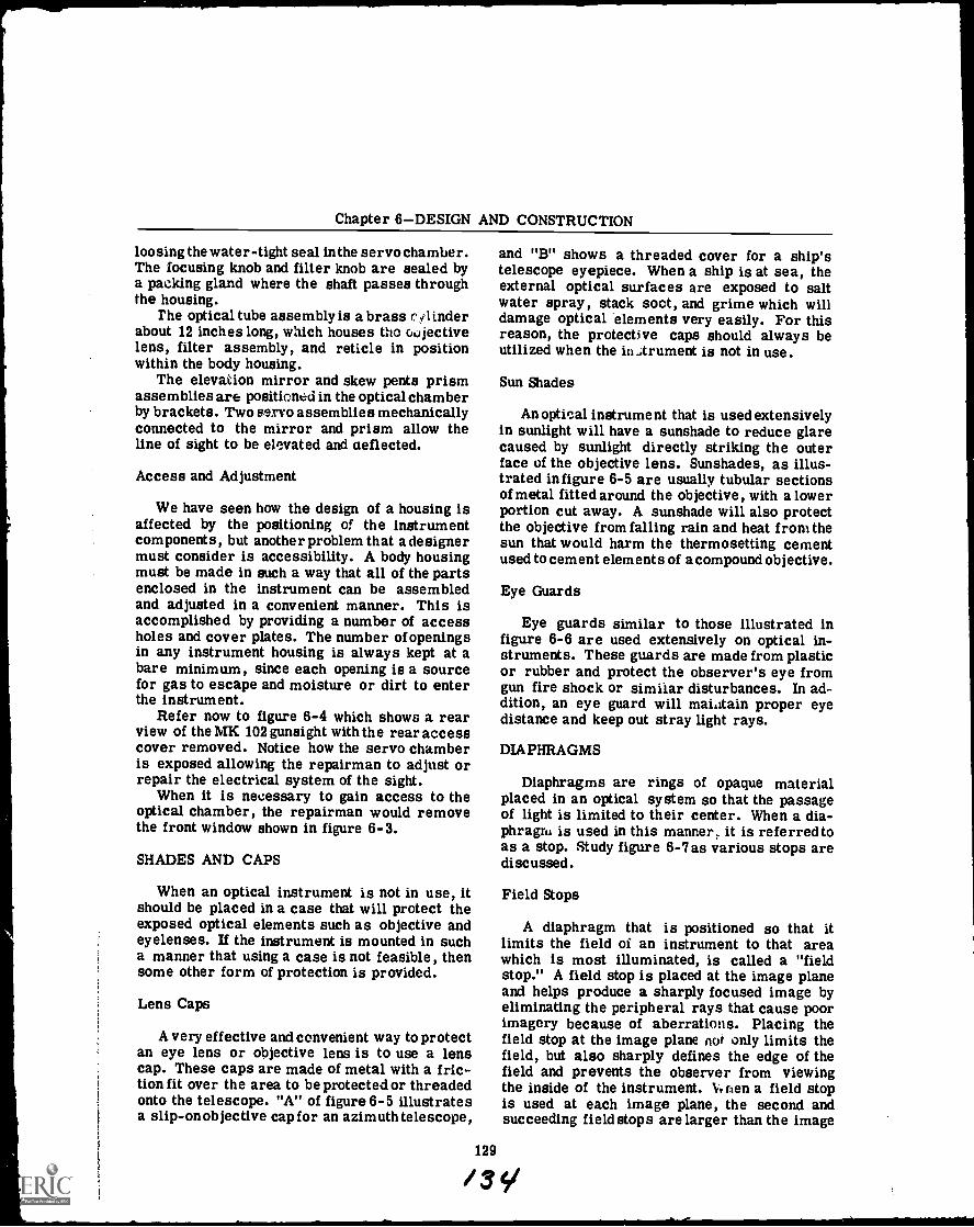
Chapter 6DESIGN AND CONSTRUCTION
loosing the water-tight seal in the servo chamber.The focusing knob and filter knob are sealed bya packing gland where the shaft passes throughthe housing.
The optical tube assembly is a brass (.0 inderabout 12 inches long, which houses the wjectivelens, filter assembly, and reticle in positionwithin the body housing.
The elevation mirror and skew pents prismassemblies are positioned in the optical chamberby brackets. Two servo assemblies mechanicallyconnected to the mirror and prism allow theline of sight to be elcvated and aeflected.
Access and Adjustment
We have seen how the design of a housing isaffected by the positioning of the instrumentcomponents, but another problem that a designermust consider is accessibility. A body housingmust be made in such a way that all of the partsenclosed in the instrument can be assembledand adjusted in a convenient manner. This isaccomplished by providing a number of accessholes and cover plates. The number of openingsin any instrument housing is always kept at abare minimum, since each opening is a sourcefor gas to escape and moisture or dirt to enterthe instrument.
Refer now to figure 6-4 which shows a rearview of the MK 102 gunsight with the rear accesscover removed. Notice how the servo chamberis exposed allowing the repairman to adjust orrepair the electrical system of the sight.
When it is necessary to gain access to theoptical chamber, the repairman would removethe front window shown in figure 6-3.
SHADES AND CAPS
When an optical instrument is not in use, itshould be placed in a case that will protect theexposed optical elements such as objective andeyelenses. If the instrument is mounted in sucha manner that using a case is not feasible, thensome other form of protection is provided.
Lens Caps
A very effective and convenient way to protectan eye lens or objective lens is to use a lenscap. These caps are made of metal with a fric-tion fit over the area to be protected or threadedonto the telescope. "A" of figure 6-5 illustratesa slip-on objective cap for an azimuth telescope,
and "B" shows a threaded cover for a ship'stelescope eyepiece. When a ship is at sea, theexternal optical surfaces are exposed to saltwater spray, stack soot, and grime which willdamage optical elements very easily. For thisreason, the protective caps should always beutilized when the in.,trument is not in use.
Sun Shades
An optical instrument that is used extensivelyin sunlight will have a sunshade to reduce glarecaused by sunlight directly striking the outerface of the objective lens. Sunshades, as illus-trated in figure 6-5 are usually tubular sectionsof metal fitted around the objective, with a lowerportion cut away. A sunshade will also protectthe objective from falling rain and heat from thesun that would harm the thermosetting cementused to cement elements of a compound objective.
129
/3
Eye Guards
Eye guards similar to those illustrated infigure 6-6 are used extensively on optical in-struments. These guards are made from plasticor rubber and protect the observer's eye fromgun fire shock or similar disturbances. In ad-dition, an eye guard will maintain proper eyedistance and keep out stray light rays.
DIAPHRAGMS
Diaphragms are rings of opaque materialplaced in an optical system so that the passageof light is limited to their center. When a dia-phragm is used in this manner; it is referredtoas a stop. Study figure 6-7as various stops arediscussed.
Field Stops
A diaphragm that is positioned so that itlimits the field of an instrument to that areawhich is most illuminated, is called a "fieldstop." A field stop is placed at the image planeand helps produce a sharply focused image byeliminating the peripheral rays that cause poorimagery because of aberrations. Placing thefield stop at the image plane not only limits thefield, but also sharply defines the edge of thefield and prevents the observer from viewingthe inside of the instrument. V,nen a field stopis used at each image plane, the second andsucceeding field stops are larger than the image
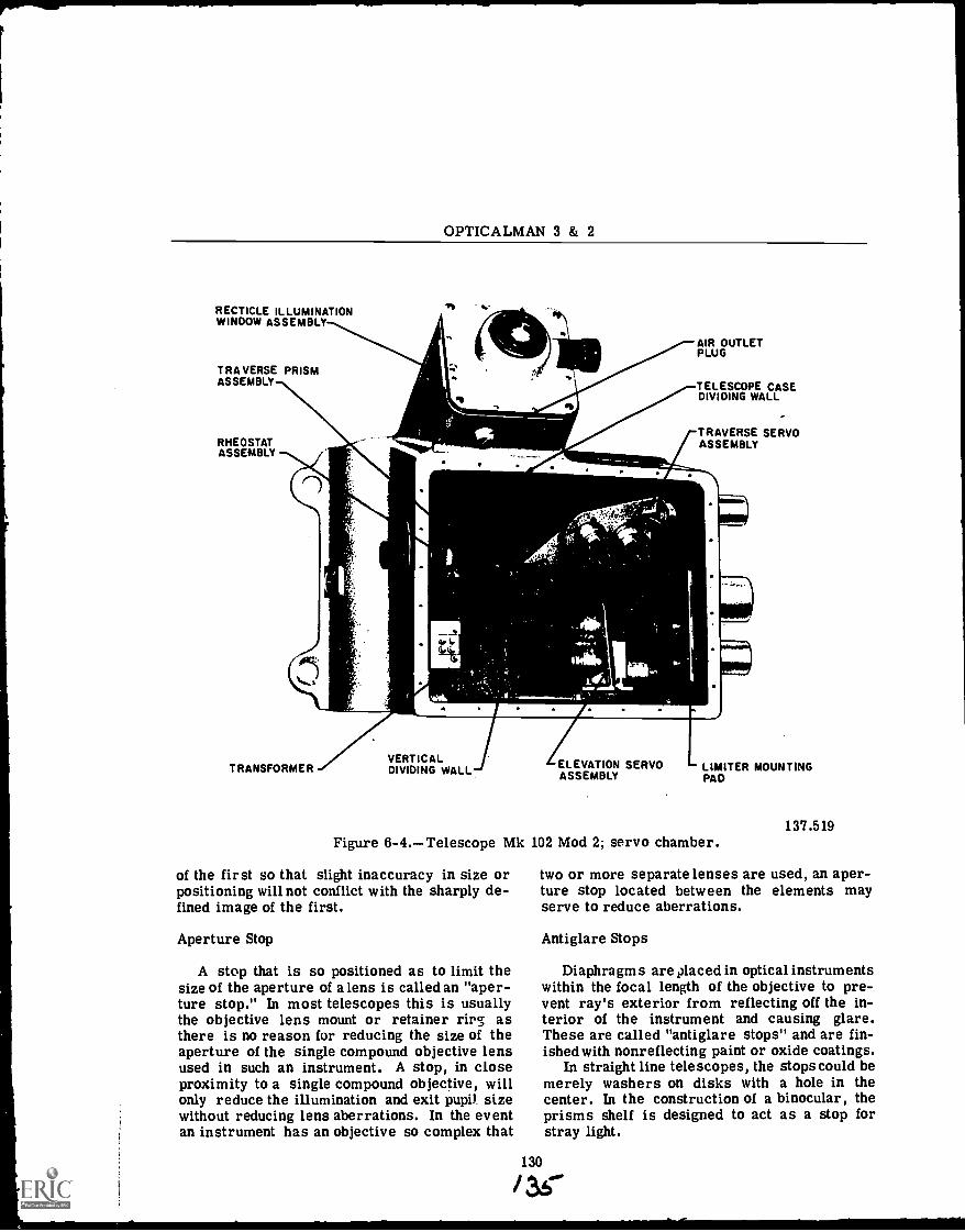
OPTICALMAN 3 & 2
RECTICLE ILLUMINATIONWINDOW ASSEMBLY
TRAVERSE PRISMASSEMBLY
RHEOSTATASSEMBLY
AIR OUTLETPLUG
TELESCOPE CASEDIVIDING WALL
TRAVERSE SERVOASSEMBLY
VERTICALTRANSFORMER DIVIDING WALL. ELEVATION SERVO
ASSEMBLYLIMITER MOUNTINGPAD
Figure 6-4.Telescope Mk 102 Mod 2; servo chamber.
of the first so that slight inaccuracy in size orpositioning will not conflict with the sharply de-fined image of the first.
Aperture Stop
A stop that is so positioned as to limit thesize of the aperture of a lens is called an "aper-ture stop." In most telescopes this is usuallythe objective lens mount or retainer rirg asthere is no reason for reducing the size of theaperture of the single compound objective lensused in such an instrument. A stop, in closeproximity to a single compound objective, willonly reduce the illumination and exit pupil sizewithout reducing lens aberrations. In the eventan instrument has an objective so complex that
/
137.519
two or more separate lenses are used, an aper-ture stop located between the elements mayserve to reduce aberrations.
Antiglare Stops
Diaphragms are placed in optical instrumentswithin the focal length of the objective to pre-vent ray's exterior from reflecting off the in-terior of the instrument and causing glare.These are called "antiglare stops" and are fin-ished with nonreflecting paint or oxide coatings.
In straight line telescopes, the stops could bemerely washers on disks with a hole in thecenter. In the construction of a binocular, theprisms shelf is designed to act as a stop forstray light.
130
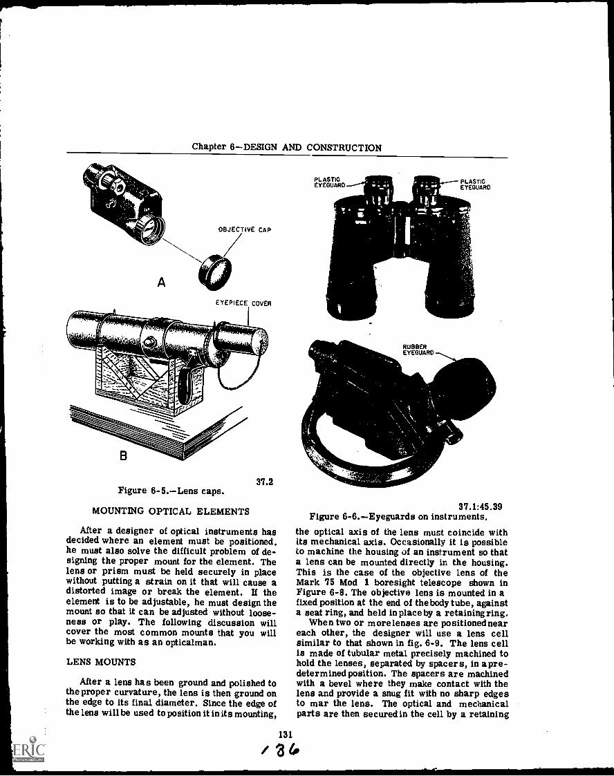
Chapter 6DESIGN AND CONSTRUCTION
OBJECTIVE CAP
A
EYEPIECE COVER
37.2Figure 6-5.Lens caps.
MOUNTING OPTICAL ELEMENTS
After a designer of optical instruments hasdecided where an element must be positioned.he must also solve the difficult problem of de-signing the proper mount for the element. Thelens or prism must be held securely in placewithout putting a strain on it that will cause adistorted image or break the element. If theelement is to be adjustable, he must design themount so that it can be adjusted without loose-ness or play. The following discussion willcover the most common mounts that you willbe working with as an opticalman.
LENS MOUNTS
After a lens has been ground and polished tothe proper curvature, the lens is then ground onthe edge to its final diameter. Since the edge ofthe lens will be used to position it in its mounting,
PLASTICEYEGUARD
PLASTICEYEGUARD
RUBBEREYEGUARD
37.1:45.39Figure 6-6.Eyeguards on instruments.
the optical axis of the lens must coincide withits mechanical axis. Occasionally it is possibleto machine the housing of an instrument so thata lens can be mounted directly in the housing.This is the case of the objective lens of theMark 75 Mod 1 boresight telescope shown inFigure 6-8. The objective lens is mounted in afixed position at the end of the body tube, againsta seat ring, and held in place by a retaining ring.
When two or more lenses are positioned neareach other, the designer will use a lens cellsimilar to that shown in fig. 6-9. The lens cellis made of tubular metal precisely machined tohold the lenses, separated by spacers, in apre-determined position. The spacers are machinedwith a bevel where they make contact with thelens and provide a snug fit with no sharp edgesto mar the lens. The optical and mechanicalparts are then secured in the cell by a retaining
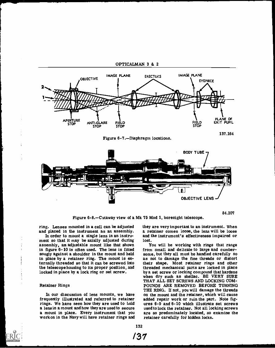
OPTICALMAN 3 & 2
1
OBJECTIVE
07,- .
IMAGE PLANE ERECTUFIS IMAGE PLANE
\ EYEPIECE
--.44141111 "0IVOIWilk" _OAT.1"__..:; 7: EMI/ 1/1" -..111111111w- II WII
APERTURESTOP ANTI-GLARE FIELD
STOPSTOP
Figure 6-7.Diaphragm locations.
FIELDSTOP
BODY TUBE
1:1111-1111r-
ma,
kPLANE OFEXIT PUPIL
OBJECTIVE LENSI
137.164
Figure 6-8.Cutaway view of a Mk 75 Mod 1, boresight telescope.
ring. Lenses mounted in a cell can be adjustedand placed in the instrument as an assembly.
In order to mount a single lens in an instru-ment so that it may be axially adjusted duringassembly, an adjustable mount like that shownin figure 6-10 is often used. The lens is fittedsnugly against a shoulder in the mount and heldin place by a retainer ring. The mount is ex-ternally threaded so that it can be screwed intothe telescope housing to its proper position, andlocked in place by a lock ring or set screw.
Retainer Rings
In our discussion of lens mounts, we havefrequently illustrated and referred to retainerrings. We have seen how they are used to holda lens in a mount and how they are used to securea mount in place. Every instrument that youwork on in the Navy will have retainer rings and
132
84.207
they are very important to an instrument. Whena retainer comes loose, the lens will be looseand the instrument's effectiveness impaired orlost.
You will be working with rings that rangefrom small and delicate to large and cumber-some, but they all must be handled carefully soas not to damage the fine threads or distorttheir shape. Most retainer rings and otherthreaded mechanical parts are locked in placeby a set screw or locking compound that hardenswhen dry such as shellac. BE VERY SURETHAT ALL SET SCREWS AND LOCKING COM-POUNDS ARE REMOVED BEFORE TURNINGTHE RING. If not, you will damage the threadson the mount and the retainer, which will causeadded repair work or ruin the part. Note fig-ures 6-9 and 6-10 which illustrate set screwsused to lock the retainer. Not all locking screwsare so predominately located, so examine theretainer carefully for hidden locks.
/37
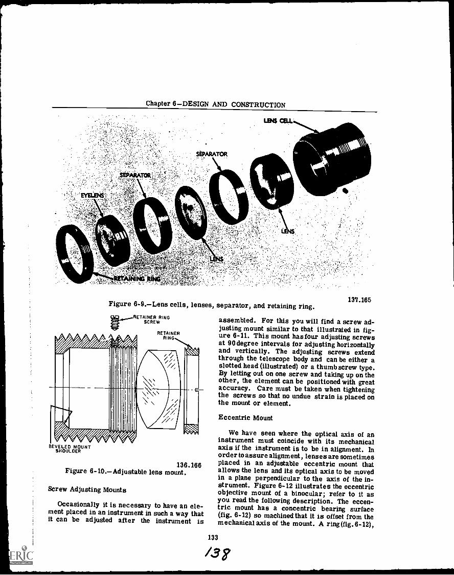
Chapter 6DESIGN AND CONSTRUCTION
Figure 6-9.Lens cells, lenses, separator, and retaining ring.RETAINER RING
SCREW
RETAINERRING
BEVELED MOUNTSHOULDER
136.166Figure 6-10.Adjustable lens mount.
Screw Adjusting Mounts
Occasionally it is necessaryment placed in an instrument init can be adjusted after the
to have an ele-such a way thatinstrument is
137.165
assembled. For this you will find a screw ad-justing mount similar to that illustrated in fig-ure 6-11. This mount has four adjusting screwsat 90 degree intervals for adjusting horizontallyand vertically. The adjusting screws extendthrough the telescope body and can be either aslotted head (illustrated) or a thumb screw type.By letting out on one screw and taking up on theother, the element can be positioned with greataccuracy. Care must be taken when tighteningthe screws so that no undue strain is placed onthe mount or element.
Eccentric Mount
We have seen where the optical axis of aninstrument must coincide with its mechanicalaxis if the instrument is to be in alignment. Inorder to assure alignment, lenses are sometimesplaced in an adjustable eccentric mount thatallows the lens and its optical axis to be movedin a plane perpendicular to the axis of the in-strument. Figure 6-12 illustrates the eccentricobjective mount of a binocular; refer to it asyou read the following description. The eccen-tric mount has a concentric bearing surface(fig. 6-12) so machined that it is offset from themechanical axis of the mount. A ring (fig. 6-12),
133
13i
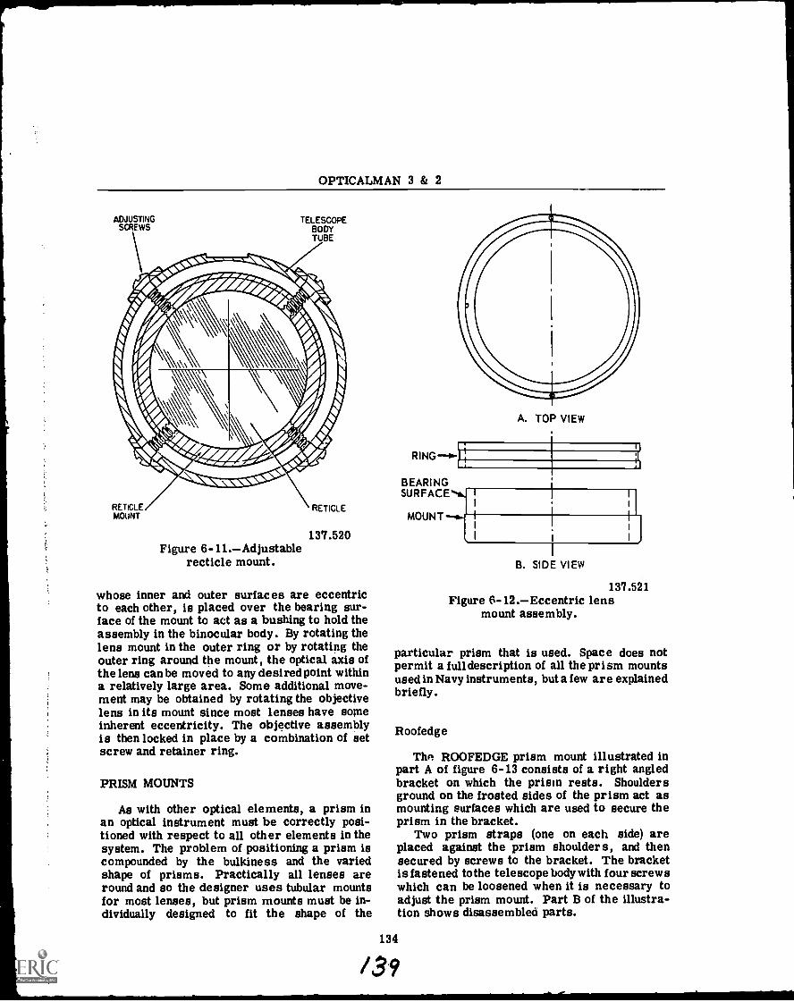
OPTICALMAN 3 & 2
ADJUSTINGSCREWS
TELESCOPEBODYTUBE
RETICLEMOUNT
RETICLE
137.520Figure 6-11.Adjustable
recticle mount.
whose inner and outer surfaces are eccentricto each other, is placed over the bearing sur-face of the mount to act as a bushing to hold theassembly in the binocular body. By rotating thelens mount in the outer ring or by rotating theouter ring around the mount, the optical axis ofthe lens can be moved to any desired point withina relatively large area. Some additional move-ment may be obtained by rotating the objectivelens in its mount since most lenses have someinherent eccentricity. The objective assemblyis then locked in place by a combination of setscrew and retainer ring.
PRISM MOUNTS
As with other optical elements, a prism inan optical instrument must be correctly posi-tioned with respect to all other elements in thesystem. The problem of positioning a prism iscompounded by the bulkiness and the variedshape of prisms. Practically all lenses areround and so the designer uses tubular mountsfor most lenses, but prism mounts must be in-dividually designed to fit the shape of the
#
BEARINGSURFACE*N.
MOUNT
A. TOP VIEW
B. SIDE VIEW
137.521Figure 6-12.Eccentric lens
mount assembly.
particular prism that is used. Space does notpermit a full description of all the prism mountsused in Navy instruments, but a few are explainedbriefly.
Roofedge
The ROOFEDGE prism mount illustrated inpart A of figure 6-13 consists of a right angledbracket on which the prism rests. Shouldersground on the frosted sides of the prism act asmounting surfaces which are used to secure theprism in the bracket.
Two prism straps (one on each side) areplaced against the prism shoulders, and thensecured by screws to the bracket. The bracketis fastened to the telescope body with four screwswhich can be loosened when it is necessary toadjust the prism mount. Part B of the illustra-tion shows disassembleci parts.
134
/39
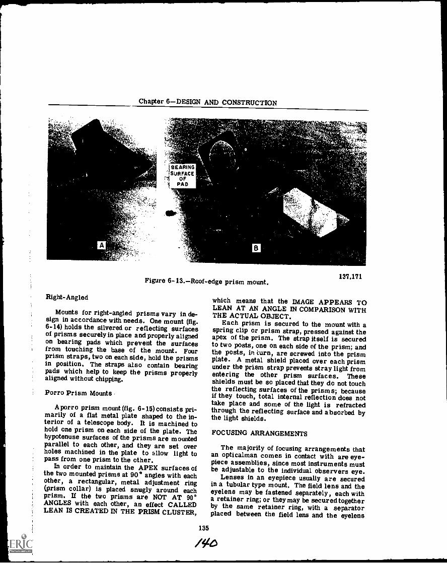
Chapter 6DESIGN AND CONSTRUCTION
A
Right-Angled
ISEARING!SURFACE
OFPAD
B
Figure 6-13.Roof-edge prism mount.
Mounts for right-angled prisms vary in de-sign in accordance with needs. One mount (fig.6-14) holds the silvered or reflecting surfacesof prisms securely in place and properly alignedon bearing pads which prevent the surfacesfrom touching the base of the mount. Fourprism straps, two on each side, hold the prismsin position. The straps also contain bearingpads which help to keep the prisms properlyaligned without chipping.
Porro Prism Mounts
A porro prism mount (fig. 6-15) consists pri-marily of a flat metal plate shaped to the in-terior of a telescope body. It is machined tohold one prism on each side of the plate. Thehypotenuse surfaces of the prisms are mountedparallel to each other, and they are set overholes machined in the plate to allow light topass from one prism to the other.
In order to maintain the APEX surfaces ofthe two mounted prisms at 90° angles with eachother, a rectangular, metal adjustment ring(prism collar) is placed snugly around eachprism. If the two prisms are NOT AT 90°ANGLES with each other, an effect CALLEDLEAN IS CREATED IN THE PRISM CLUSTER,
- ,4:07"
'1.6 N.
137.171
which means that the IMAGE APPEARS TOLEAN AT AN ANGLE IN COMPARISON WITHTHE ACTUAL OBJECT.
Each prism is secured to the mount with aspring clip or prism strap, pressed against theapex of the prism. The strap itself is securedto two posts, one on each side of the prism; andthe posts, in turn, are screwed into the prismplate. A metal shield placed over each prismunder the prism strap prevents stray light fromentering the other prism surfaces. Theseshields must be so placed that they do not touchthe reflecting surfaces of the prisms; becauseif they touch, total internal reflection does nottake place and some of the light is refractedthrough the reflecting surface and absorbed bythe light shields.
135
FOCUSING ARRANGEMENTS
The majority of focusing arrangements thatan opticalman comes in contact with are eye-piece assemblies, since most instruments mustbe adjustable to the individual observers eye.
Lenses in an eyepiece usually are securedin a tubular type mount. The field lens and theeyelens may be fastened separately, each witha retainer ring; or they may be secured togetherby the same retainer ring, with a separatorplaced between the field lens and the eyelens
/VD
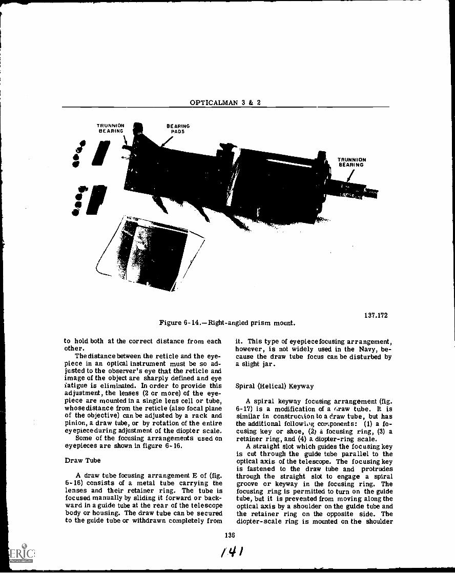
OPTICALMAN 3 & 2
TRUNNIONBEARING
1_
BEARINGPADS
Figure 6- 14.Right-angled prism mount.
to hold both at the correct distance from eachother.
Thedistance between the reticle and the eye-piece in an optical instrument must be so ad-justed to the observer's eye that the reticle andimage of the object are sharply defined and eyefatigue is eliminated. In order to provide thisadjustment, the lenses (2 or more) of the eye-piece are mounted in a single lens cell or tube,whose distance from the reticle (also focal planeof the objective) can be adjusted by a rack andpinion, a draw tube, or by rotation of the entireeyepiece during adjustment of the diopter scale.
Some of the focusing arrangements used oneyepieces are shown in figure 6-16.
Draw Tube
A draw tube focusing arrangement E of (fig.6-16) consists of a metal tube carrying thelenses and their retainer ring. The tube isfocused manually by sliding it forward or back-ward in a guide tube at the rear of the telescopebody or housing. The draw tube can be securedto the guide tube or withdrawn completely from
136
TRUNNIONBEARING
137.172
it. This type of eyepiece focusing arrangement,however, is not widely used in the Navy, be-cause the draw tube focus can be disturbed bya slight jar.
Spiral (Helical) Keyway
A spiral keyway focusing arrangement (fig.6-17) is a modification of a rtraw tube. It issimilar in construction to a draw tube, but hasthe additional followiog components: (1) a fo-cusing key or shoe, (2) a focusing ring, (3) aretainer ring, and (4) a diopter-ring scale.
A straight slot which guides the focusing keyis cut through the guide tube parallel to theoptical axis of the telescope. The focusing keyis fastened to the draw tube and protrudesthrough the straight slot to engage a spiralgroove or keyway in the focusing ring. Thefocusing ring is permitted to turn on the guidetube, but it is prevented from moving along theoptical axis by a shoulder on the guide tube andthe retainer ring on the opposite side. Thediopter-scale ring is mounted on the shoulder
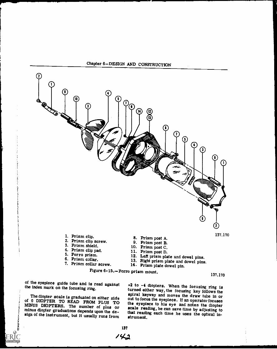
Chapter 6DESIGN AND CONSTRUCTION
137.1701. Prism clip. 8. Prism post A.2. Prism clip screw. 9. Prism post B.3. Prism shield. 10. Prism post C.4. Prism clip pad. 11. Prism post D.5. Porro prism. 12. Left prism plate and dowel pins.6. Prism collar. 13. Right prism plate and dowel pins.7. Prism collar screw. 14. Prism plate dowel pin.
Figure 6-15.Porro prism mount.
of the eyepiece guide tube and is read againstthe index mark on the focusing ring.
The diopter scale is graduated on either sideof 0 DIOPTER TO READ FROM PLUS TOMINUS DIOPTERS. The number of plus orminus diopter graduations depends upon the de-sign of the instrument, but it usually runs from
137.170
+2 to -4 diopters. When the focusing ring isturned either way, the focusing key follows thespiral keyway and moves the draw tube in orout to focus the eyepiece. If an operator focusesthe eyepiece to his eye and notes the diopterscale reading, he can save time by adjusting tothat reading each time he uses the optical in-strument.
137
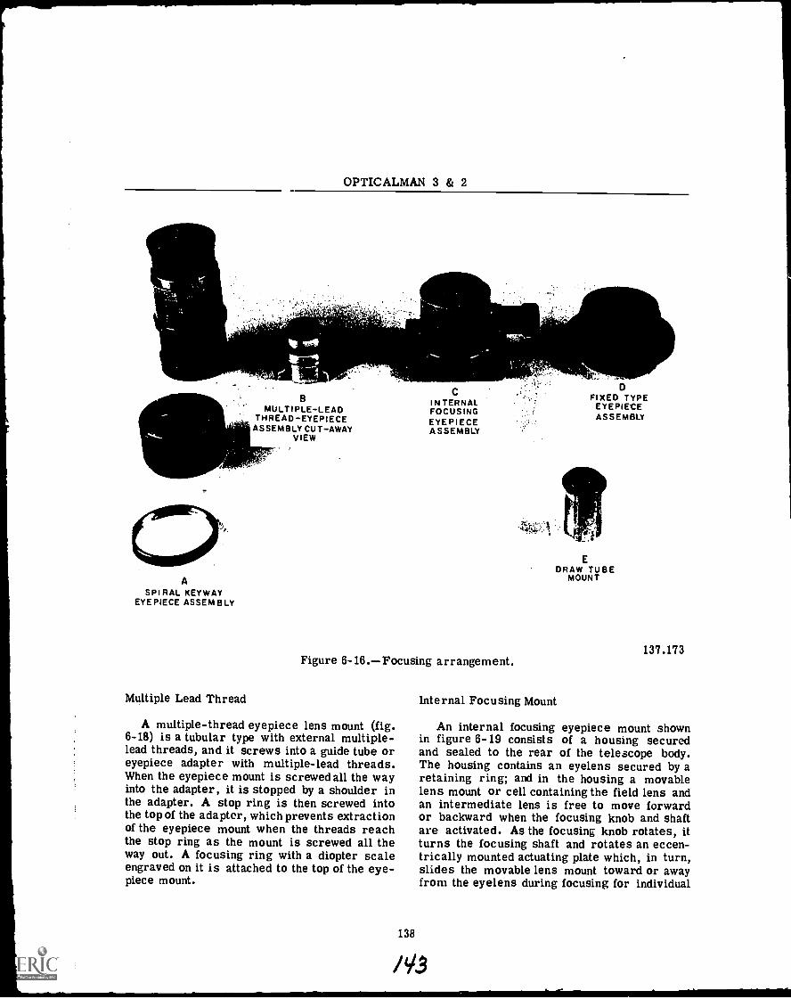
OPTICALMAN 3 & 2
BMULTIPLE-LEAD
THREAD-EYEPIECEASSEMBLY CUT-AWAY
VIEW
ASPIRAL KEYWAY
EYEPIECE ASSEMBLY
Multiple Lead Thread
CINTERNALFOCUSINGEYEPIECEASSEMBLY
FIXED TYPEEYEPIECEASSEMBLY
EDRAW TUBE
MOUNT
137.173Figure 6-16.Focusing arrangement.
A multiple-thread eyepiece lens mount (fig.6-18) is a tubular type with external multiple-lead threads, and it screws into a guide tube oreyepiece adapter with multiple-lead threads.When the eyepiece mount is screwed all the wayinto the adapter, it is stopped by a shoulder inthe adapter. A stop ring is then screwed intothe top of the adaptor, which prevents extractionof the eyepiece mount when the threads reachthe stop ring as the mount is screwed all theway out. A focusing ring with a diopter scaleengraved on it is attached to the top of the eye-piece mount.
138
Internal Focusing Mount
An internal focusing eyepiece mount shownin figure 6-19 consists of a housing securedand sealed to the rear of the telescope body.The housing contains an eyelens secured by aretaining ring; and in the housing a movablelens mount or cell containing the field lens andan intermediate lens is free to move forwardor backward when the focusing knob and shaftare activated. As the focusing knob rotates, itturns the focusing shaft and rotates an eccen-trically mounted actuating plate which, in turn,slides the movable lens mount toward or awayfrom the eyelens during focusing for individual
/V3
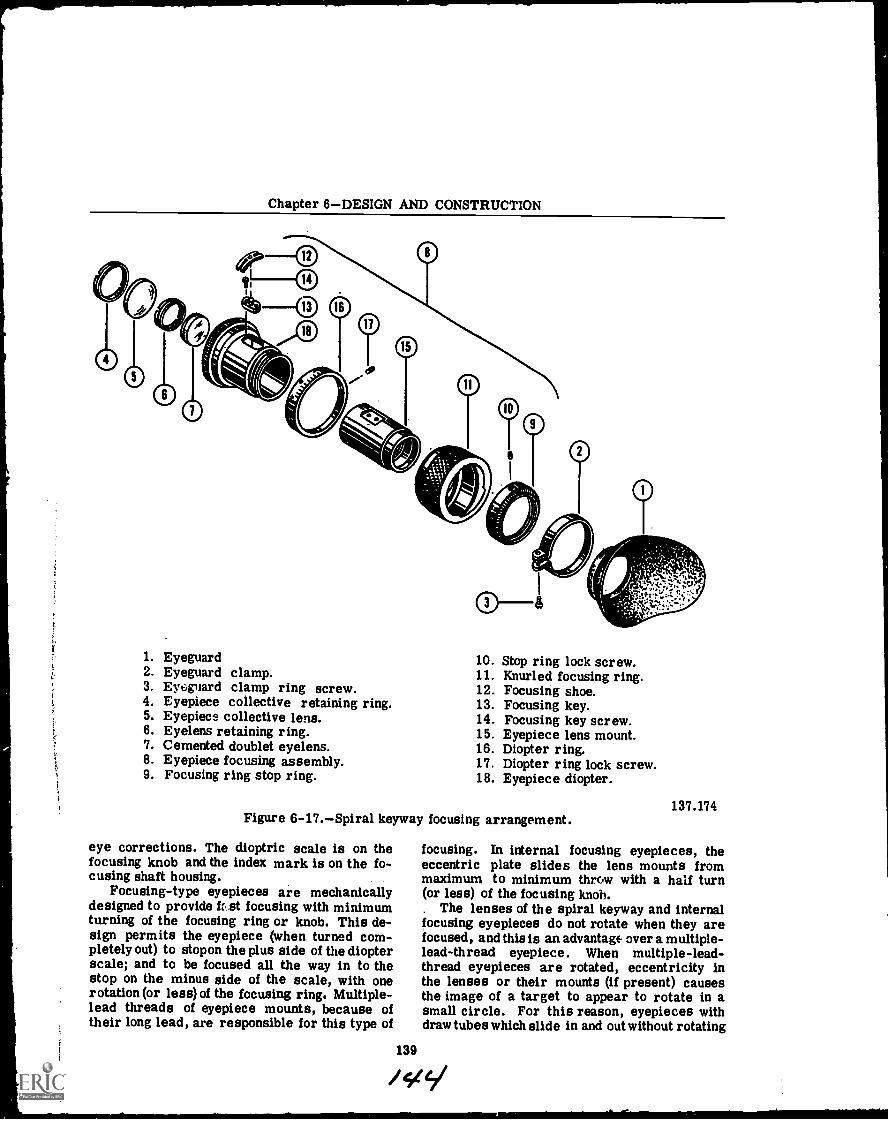
Chapter 6DESIGN AND CONSTRUCTION
1. Eyeguard2. Eyeguard clamp.3. Eyeguard clamp ring screw.4. Eyepiece collective retaining ring.5. Eyepiece collective lens.6. Eyelens retaining ring.7. Cemented doublet eyelens.8. Eyepiece focusing assembly.9. Focusing ring stop ring.
10. Stop ring lock screw.11. Knurled focusing ring.12. Focusing shoe.13. Focusing key.14. Focusing key screw.15. Eyepiece lens mount.16. Diopter ring.17. Diopter ring lock screw.18. Eyepiece diopter.
Figure 6-17.Spiral keyway focusing arrangement.
eye corrections. The dioptric scale is on thefocusing knob and the index mark is on the fo-cusing shaft housing.
Focusing-type eyepieces are mechanicallydesigned to provide ft.st focusing with minimumturning of the focusing ring or knob. This de-sign permits the eyepiece (when turned com-pletely out) to stop on the plus side of the diopterscale; and to be focused all the way in to thestop on the minus side of the scale, with onerotation (or less) of the focusing ring. Multiple-lead threads of eyepiece mounts, because oftheir long lead, are responsible for this type of
137.174
focusing. In internal focusing eyepieces, theeccentric plate slides the lens mounts frommaximum to minimum throw with a half turn(or less) of the focusing knob.
The lenses of the spiral keyway and internalfocusing eyepieces do not rotate when they arefocused, and this is an advantage over a multiple-lead-thread eyepiece. When multiple-lead-thread eyepieces are rotated, eccentricity inthe lenses or their mounts (if present) causesthe image of a target to appear to rotate in asmall circle. For this reason, eyepieces withdraw tubes which slide in and out without rotating
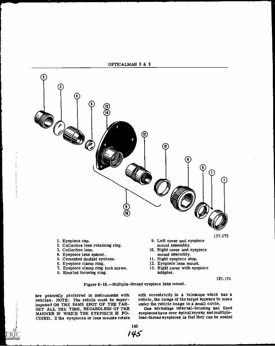
OPTICALMAN 3 & 2
1. Eyepiece cap.2. Collective lens retaining ring.3. Collective lens.4. Eyepiece lens spacer.5. Cemented doublet eyelens.6. Eyepiece clamp ring.7. Eyepiece clamp ring lock screw.8. Knurled focusing ring.
9. Left cover and eyepiecemount assembly.
10. Right cover and eyepiecemount assembly.
11. Right eyepiece stop.12. Eyepiece lens mount.13. Right cover with eyepiece
adapter.
Figure 6- 18.Multiple-thread eyepiece lens mount.
are generally preferred in instruments withreticles. NOTE: The reticle must be super-imposed ON THE SAME SPOT OF THE TAR-GET ALL THE TIME, REGARDLESS OF THEMANNER IN WHICH THE EYEPIECE IS FO-CUSED. If the eyepieces or lens mounts rotate
140
137.175
137.175
with eccentricity in a telescope which has areticle, the image of the target appears to moveunder the reticle image in a small circle.
One advantage internal-focusing and fixedeyepieces have over spiral keyway and multiple-lead-thread eyepieces is that they can be sealed
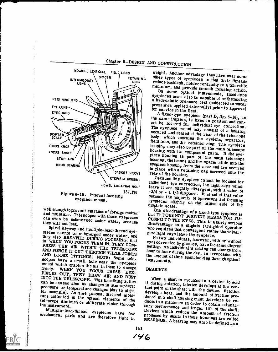
Chapter 6DESIGN AND CONSTRUCTION
MOVABLE LENS CELL. FIELD LENSSPACER RETAINING
RINGINTERMEDIATELENS
RETAINING RING
EYE LENS
EYEGUARD
DIOPTERSCALE
FOCUS KNOB
FOCUS SHAFT
STOP ARM
KNOB BEARING
GASKET GROOVE
EYEPIECE HOUSING
DOWEL LOCATING HOLE
137.176Figure 6-19.Internal focusingeyepiece mount.
well enough to prevent entrance of foreign matterand moisture. Telescopes with these eyepiecescan even be submerged under water, becausethey will not leak.Spiral keyway and multiple-lead-thread eye-pieces cannot be submerged under water, andthey also BREATHE DURING FOCUSING; thatis, WHEN YOU FOCUS THEM IN, THEY COM-PRESS THE AIR WITHIN THE TELESCOPEAND FORCE IT OUT THROUGH THEIR JOINTSAND LOOSE FITTINGS. NOTE: Some tele-scopes have a small hole near the eyepiecemount which enables the air in them to escapefreely. WHEN YOU FOCUS THESE EYE-PIECES OUT, THEY DRAW AIR AND DUSTINTO THE TELESCOPE. This breathing actioncan be caused also by changes in atmosphericpressure or temperature changes (day to night,for example). As time passes, dirt and mois-ture collected in the optical elements of thetelescope diminish or obliterate vision throughthe instrument.
Multiple-lead-thread eyepieces have fewmechanical parts and are therefore light in
weight. Another advantage they have over someother types of eyepieces is that their threadsreduce backlash, hold eccentricity to a tolerableminimum, and provide smooth focusing action.On some optical instruments, fixed-typeeyepieces must also be capable of withstandinga hydrostatic pressure test (subjected to waterpressures applied externally) prior to approvalfor service in the fleet.A fixed-type eyepiece (part D, fig. 6-16), asthe name implies, is fixed in position and can-not be focused for individual eye correction.The eyepiece mount may consist of a housingsecured and sealed at the rear of the telescopebody, which contains the eyelens, separator,field lens, and the retainer ring. The eyepiecehousing may also be part of the main telescopehousing with its component parts. If the eye-piece housing is part of the main telescopehousing, the lenses and the spacer slide into theeyepiece housing from the rear and are securedin place with a retaining cap screwed onto therear of the housing.
Because this eyepiece cannot be focused forindividual eye correction, the light rays whichleave it are slightly divergent, with a value of-3/4 or - 1 1/2 diopters. It is set at this valuebecause the majority of operators set focusingeyepieces slightly on the minus side of thedioptric scale.One disadvantage of P fixed-type eyepiece isthat IT DOES NOT PROVIDE MEANS FOR FO-CUSING TO THE EYES. This is a fairly seriousdisadvantage to a slightly farsighted operatorwho requires that convergent rather thandiver-gent light rays leave the eyepiece.No two individuals, however, with or withouteyes corrected by glasses, have the same dioptersetting. An individual's setting can change fromhour to hour during the day, in accordance withthe amount of time spent looking through opticalinstruments.
141
BEARINGS
When a shaft is mounted in a device to iloldit during rotation, friction develops at the con-tact point of the shaft with the device. Frictiondevelops heat, and the amount of friction pro-duced in a shaft housing must therefore be re-ducedto a minimum in order to obtain satisfac-tory performance and longer life of the shaft.Devices which reduce the amount of frictionproduced by shafts in their housings are calledBEARINGS. A bearing may also be defined as a
i416
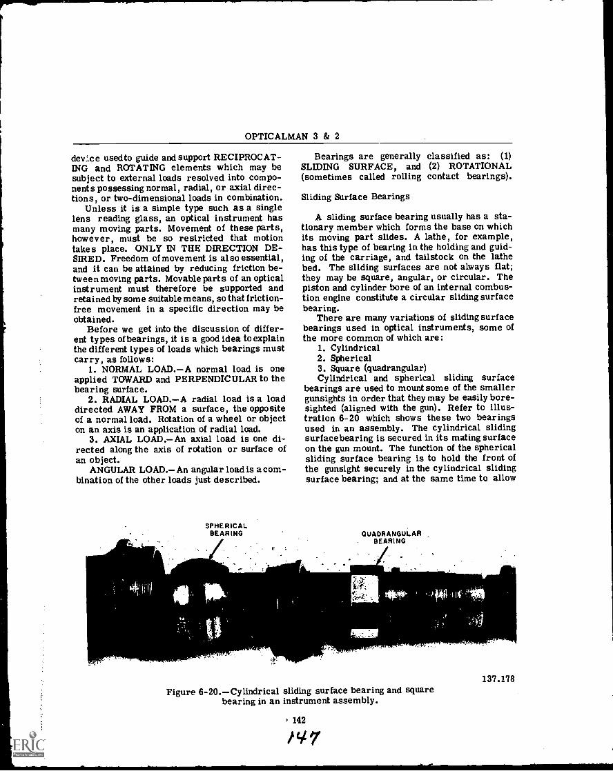
OPTICALMAN 3 & 2
device used to guide and support RECIPROCAT-ING and ROTATING elements which may besubject to external loads resolved into compo-nents possessing normal, radial, or axial direc-tions, or two-dimensional loads in combination.
Unless it is a simple type such as a singlelens reading glass, an optical instrument hasmany moving parts. Movement of these parts,however, must be so restricted that motiontakes place. ONLY IN THE DIRECTION DE-SIRED. Freedom of movement is also essential,and it can be attained by reducing friction be-tween moving parts. Movable parts of an opticalinstrument must therefore be supported andretained by some suitable means, so that friction-free movement in a specific direction may beobtained.
Before we get into the discussion of differ-ent types of bearings, it is a good idea to explainthe different types of loads which bearings mustcarry, as follows:
1. NORMAL LOAD.A normal load is oneapplied TOWARD and PERPENDICULAR to thebearing surface.
2. RADIAL LOAD.A radial load is a loaddirected AWAY FROM a surface, the oppositeof a normal load. Rotation of a wheel or objecton an axis is an application of radial load.
3. AXIAL LOAD.An axial load is one di-rected along the axis of rotation or surface ofan object.
ANGULAR LOAD.An angular load is a com-bination of the other loads just described.
rr
SPHERICALBEARING
r .
Bearings are generally classified as: (1)SLIDING SURFACE, and (2) ROTATIONAL(sometimes called rolling contact bearings).
Sliding Surface Bearings
A sliding surface bearing usually has a sta-tionary member which forms the base on whichits moving part slides. A lathe, for example,has this type of bearing in the holding and guid-ing of the carriage, and tailstock on the lathebed. The sliding surfaces are not always flat;they may be square, angular, or circular. Thepiston and cylinder bore of an internal combus-tion engine constitute a circular sliding surfacebearing.
There are many variations of sliding surfacebearings used in optical instruments, some ofthe more common of which are:
1. Cylindrical2. Spherical3. Square (quadrangular)Cylindrical and spherical sliding surface
bearings are used to mount some of the smallergunsights in order that they may be easily bore-sighted (aligned with the gun). Refer to illus-tration 6-20 which shows these two bearingsused in an assembly. The cylindrical slidingsurface bearing is secured in its mating surfaceon the gun mount. The function of the sphericalsliding surface bearing is to hold the front ofthe gunsight securely in the cylindrical slidingsurface bearing; and at the same time to allow
NA-
QUADRANGULARBEARING
'11.1111._1111__
Figure 6-20.Cylindrical sliding surface bearing and squarebearing in an instrument assembly.
142
1/7
Ai
137.178
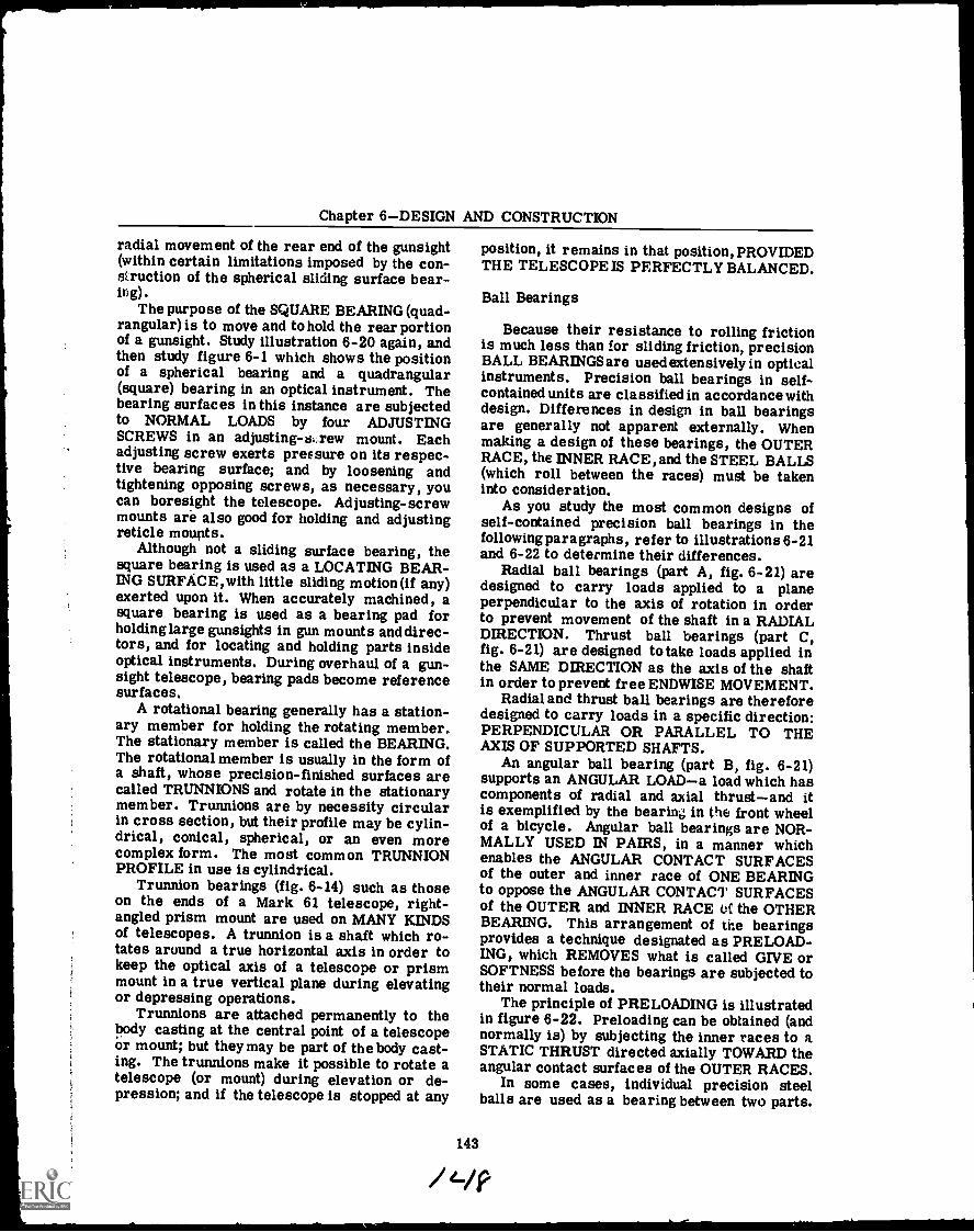
Chapter 6DESIGN AND CONSTRUCTION
radial movement of the rear end of the gunsight(within certain limitations imposed by the con-struction of the spherical sliding surface bear-ing).
The purpose of the SQUARE BEARING (quad-rangular) is to move and to hold the rear portionof a gunsight. Study illustration 6-20 again, andthen study figure 6-1 which shows the positionof a spherical bearing and a quadrangular(square) bearing in an optical instrument. Thebearing surfaces in this instance are subjectedto NORMAL LOADS by four ADJUSTINGSCREWS in an adjusting-si.rew mount. Eachadjusting screw exerts pressure on its respec-tive bearing surface; and by loosening andtightening opposing screws, as necessary, youcan boresight the telescope. Adjusting-screwmounts are also good for holding and adjustingreticle mounts.
Although not a sliding surface bearing, thesquare bearing is used as a LOCATING BEAR-ING SURFACE,with little sliding motion (if any)exerted upon it. When accurately machined, asquare bearing is used as a bearing pad forholding large gunsights in gun mounts anddirec-tors, and for locating and holding parts insideoptical instruments. During overhaul of a gun-sight telescope, bearing pads become referencesurfaces.
A rotational bearing generally has a station-ary member for holding the rotating member..The stationary member is called the BEARING.The rotational member is usually in the form ofa shaft, whose precision-finished surfaces arecalled TRUNNIONS and rotate in the stationarymember. Trunnions are by necessity circularin cross section, but their profile may be cylin-drical, conical, spherical, or an even morecomplex form. The most common TRUNNIONPROFILE in use is cylindrical.
Trunnion bearings (fig. 6-14) such as thoseon the ends of a Mark 61 telescope, right-angled prism mount are used on MANY KINDSof telescopes. A trunnion is a shaft which ro-tates around a true horizontal axis in order tokeep the optical axis of a telescope or prismmount in a true vertical plane during elevatingor depressing operations.
Trunnions are attached permanently to thebody casting at the central point of a telescopeor mount; but they may be part of the body cast-ing. The trunnions make it possible to rotate atelescope (or mount) during elevation or de-pression; and if the telescope is stopped at any
position, it remains in that position, PROVIDEDTHE TELESCOPE IS PERFECTLY BALANCED.
Ball Bearings
Because their resistance to rolling frictionis much less than for sliding friction, precisionBALL BEARINGS are used extensively in opticalinstruments. Precision ball bearings in self-contained units are classified in accordance withdesign. Differences in design in ball bearingsare generally not apparent externally. Whenmaking a design of these bearings, the OUTERRACE, the INNER RACE, and the STEEL BALLS(which roll between the races) must be takeninto consideration.
As you study the most common designs ofself-contained precision ball bearings in thefollowing paragraphs, refer to illustrations 6-21and 6-22 to determine their differences.
Radial ball bearings (part A, fig. 6-21) aredesigned to carry loads applied to a planeperpendicular to the axis of rotation in orderto prevent movement of the shaft in a RADIALDIRECTION. Thrust ball bearings (part C,fig. 6-21) are designed to take loads applied inthe SAME DIRECTION as the axis of the shaftin order to prevent free ENDWISE MOVEMENT.
Radial and thrust ball bearings are thereforedesigned to carry loads in a specific direction:PERPENDICULAR OR PARALLEL TO THEAXIS OF SUPPORTED SHAFTS.
An angular ball bearing (part B, fig. 6-21)supports an ANGULAR LOADa load which hascomponents of radial and axial thrustand itis exemplified by the bearing in the front wheelof a bicycle. Angular ball bearings are NOR-MALLY USED IN PAIRS, in a manner whichenables the ANGULAR CONTACT SURFACESof the outer and inner race of ONE BEARINGto oppose the ANGULAR CONTACT SURFACESof the OUTER and INNER RACE oC the OTHERBEARING. This arrangement of the bearingsprovides a technique designated as PRELOAD-ING, which REMOVES what is called GIVE orSOFTNESS before the bearings are subjected totheir normal loads.
The principle of PRELOADING is illustratedin figure 6-22. Pre loading can be obtained (andnormally is) by subjecting the inner races to aSTATIC THRUST directed axially TOWARD theangular contact surfaces of the OUTER RACES.
In some cases, individual precision steelballs are used as a bearing between two parts.
143
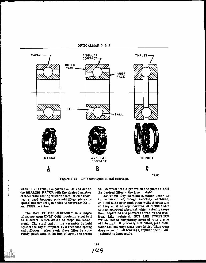
OPTICALMAN 3 & 2
RADIAL
OUTERRACE
RADIAL
A
CAGE
ANGULARCONTACT
ANGULARCONTACT
INNERRACE
BALL
THRUST
B C
Figure 6-21.Different types of ball bearings.
When this is true, the parts themselves act asthe BEARING RACES, with the desired numberof steel balls rolling between them. Such a bear-ing is used between polaroid filter plates inoptical instruments, in order to secure SMOOTHand FREE rotation.
The RAY FILTER ASSEMBLY in a ship'stelescope uses ONLY ONE precision steel ballas a detent, which starts or stops the move-ment. The steel ball in this assembly is heldagainst the ray filter plate by a recessed springand follower. When each glass filter is cor-rectly positioned in the line of sight, the detent
77:66
ball is thrust into a groove on the plate to holdthe desired filter in the line of sight.
CAUTION: Dry metallic surfaces under anappreciable load, though smoothly machined,will not slide over each other without abrasion;so they must be kept covered CONTINUALLYwith an approved lubricant, which actually keepsthem separated and prevents abrasion and fric-tion. Like metals do NOT RUB TOGETHERWELL unless completely covered with a filmof lubricant. If properly lubricated, precision-made ball bearings wear very little. When weardoes occur in ball bearings, replace them. Ad-justment is impossible.
144
9
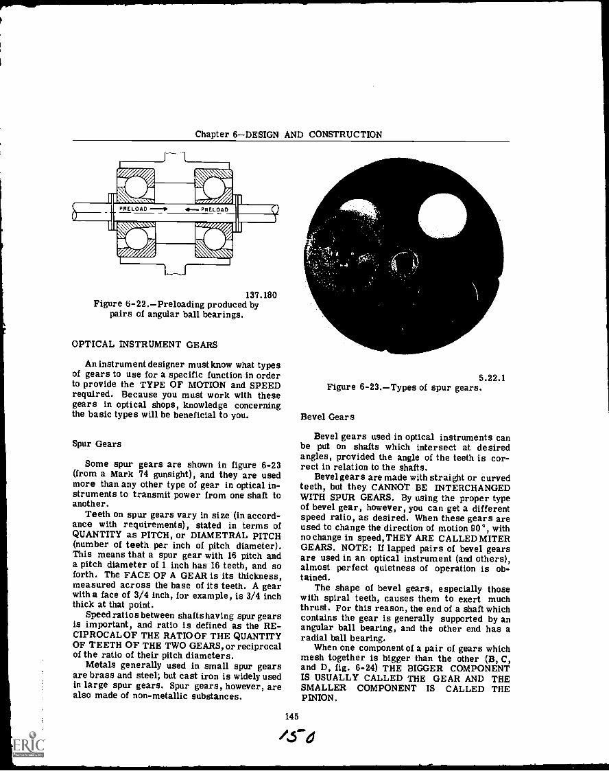
Chapter 6DESIGN AND CONSTRUCTION
0
I"r fir""-.441W137.180
Figure 6-22.Preloading produced bypairs of angular ball bearings.
OPTICAL INSTRUMENT GEARS
An instrument designer must know what typesof gears to use for a specific function in orderto provide the TYPE OF MOTION and SPEEDrequired. Because you must work with thesegears in optical shops, knowledge concerningthe basic types will be beneficial to you.
Spur Gears
Some spur gears are shown in figure 6-23(from a Mark 74 gunsight), and they are usedmore than any other type of gear in optical in-struments to transmit power from one shaft toanother.
Teeth on spur gears vary in size (in accord-ance with requirements), stated in terms ofQUANTITY as PITCH, or DIAMETRAL PITCH(number of teeth per inch of pitch diameter).This means that a spur gear with 16 pitch anda pitch diameter of 1 inch has 16 teeth, and soforth. The FACE OF A GEAR is its thickness,measured across the base of its teeth. A gearwith a face of 3/4 inch, for example, is 3/4 inchthick at that point.
Speed ratios between shafts having spur gearsis important, and ratio is defined as the RE-CIPROCAL OF THE RATIOOF THE QUANTITYOF TEETH OF THE TWO GEARS, or reciprocalof the ratio of their pitch diameters.
Metals generally used in small spur gearsare brass and steel; but cast iron is widely usedin large spur gears. Spur gears, however, arealso made of non-metallic substances.
5.22.1Figure 6-23.Types of spur gears.
Bevel Gear s
Bevel gears used in optical instruments canbe put on shafts which intersect at desiredangles, provided the angle of the teeth is cor-rect in relation to the shafts.
Bevel gears are made with straight or curvedteeth, but they CANNOT BE INTERCHANGEDWITH SPUR GEARS. By using the proper typeof bevel gear, however, you can get a differentspeed ratio, as desired. When these gears areused to change the direction of motion 90°, withno change in speed, THEY ARE CALLED MITERGEARS. NOTE: If lapped pairs of bevel gearsare used in an optical instrument (and others),almost perfect quietness of operation is ob-tained.
The shape of bevel gears, especially thosewith spiral teeth, causes them to exert muchthrust. For this reason, the end of a shaft whichcontains the gear is generally supported by anangular ball bearing, and the other end has aradial ball bearing.
When one component of a pair of gears whichmesh together is bigger than the other (B, C,and D, fig. 6-24) THE BIGGER COMPONENTIS USUALLY CALLED THE GEAR AND THESMALLER COMPONENT IS CALLED THEPINION.
145
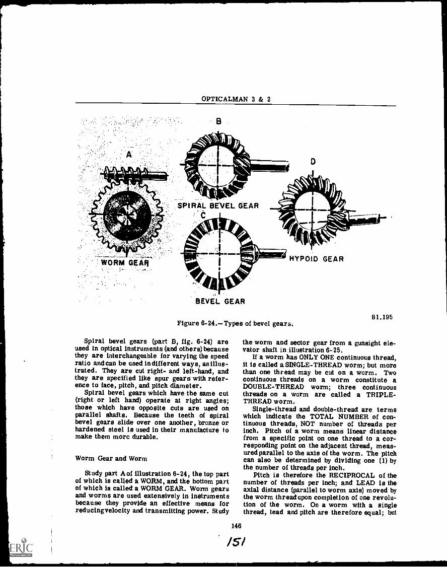
OPTICALMAN 3 & 2
D
BEVEL GEAR
HYPOID GEAR
Figure 6-24.Types of bevel gears.
Spiral bevel gears (part B, fig. 6-24) areused in optical instruments (and others) becausethey are interchangeable for varying the speedratio and can be used indifferent ways, as illus-trated. They are cut right- and left-hand, andthey are specified like spur gears with refer-ence to face, pitch, and pitch diameter.
Spiral bevel gears which have the same cut(right or left hand) operate at right angles;those which have opposite cuts are used onparallel shafts. Because the teeth of spiralbevel gears slide over one another, bronze orhardened steel is used in their manufacture tomake them more durable.
Worm Gear and Worm
Study part A of illustration 6-24, the top partof which is called a WORM, and the bottom partof which is called a WORM GEAR. Worm gearsand worms are used extensively in instrumentsbecause they provide an effective means forreducingvelocity and transmitting power. Study
146
81.195
the worm and sector gear from a gunsight ele-vator shaft in illustration 6-25.
If a worm has ONLY ONE continuous thread,it is called a SINGLE-THREAD worm; but morethan one thread may be cut on a worm. Twocontinuous threads on a worm constitute aDOUBLE-THREAD worm; three continuousthreads on a worm are called a TRIPLE-THREAD worm.
Single-thread and double-thread are termswhich indicate the TOTAL NUMBER of con-tinuous threads, NOT number of threads perinch. Pitch of a worm means linear distancefrom a specific point on one thread to a cor-responding point on the adjacent thread, meas-ured parallel to the axis of the worm. The pitchcan also be determined by dividing one (1) bythe number of threads per inch.
Pitch is therefore the RECIPROCAL of thenumber of threads per inch; and LEAD is theaxial distance (parallel to worm axis) moved bythe worm thread upon completion of one revolu-tion of the worm. On a worm with a singlethread, lead and pitch are therefore equal; but
/5/
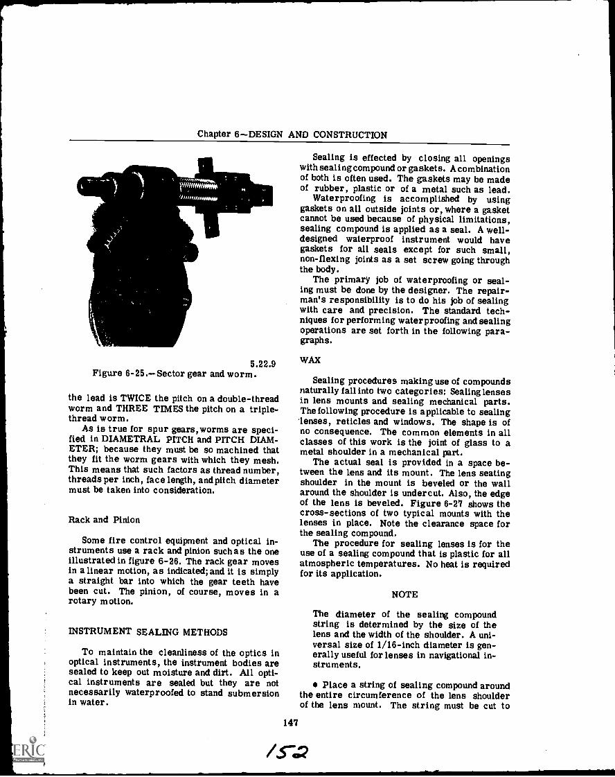
Chapter 6DESIGN AND CONSTRUCTION
5.22.9Figure 6-25.Sector gear and worm.
the lead is TWICE the pitch on a double-threadworm and THREE TIMES the pitch on a triple-thread worm.
As is true for spur gears,worms are speci-fied in DIAMETRAL PITCH and PITCH DIAM-ETER; because they must be so machined thatthey fit the worm gears with which they mesh.This means that such factors as thread number,threads per inch, face length, and pitch diametermust be taken into consideration.
Rack and Pinion
Some fire control equipment and optical in-struments use a rack and pinion such as the oneillustrated in figure 6-26. The rack gear movesin a linear motion, as indicated; and it is simplya straight bar into which the gear teeth havebeen cut. The pinion, of course, moves in arotary motion.
INSTRUMENT SEALING METHODS
To maintain the cleanliness of the optics inoptical instruments, the instrument bodies aresealed to keep out moisture and dirt. All opti-cal instruments are sealed but they are notnecessarily waterproofed to stand submersionin water.
Sealing is effected by closing all openingswith sealing compound or gaskets. A combinationof both is often used. The gaskets may be madeof rubber, plastic or of a metal such as lead.
Waterproofing is accomplished by usinggaskets on all outside joints or, where a gasketcannot be used because of physical limitations,sealing compound is applied as a seal. A well-designed waterproof instrument would havegaskets for all seals except for such small,non-flexing joints as a set screw going throughthe body.
The primary job of waterproofing or seal-ing must be done by the designer. The repair-man's responsibility is to do his job of sealingwith care and precision. The standard tech-niques for performing waterproofing and sealingoperations are set forth in the following para-graphs.
WAX
Sealing procedures making use of compoundsnaturally fall into two categories: Sealing lensesin lens mounts and sealing mechanical parts.The following procedure is applicable to sealinglenses, reticles and windows. The shape is ofno consequence. The common elements in allclasses of this work is the joint of glass to ametal shoulder in a mechanical part.
The actual seal is provided in a space be-tween the lens and its mount. The lens seatingshoulder in the mount is beveled or the wallaround the shoulder is undercut. Also, the edgeof the lens is beveled. Figure 6-27 shows thecross-sections of two typical mounts with thelenses in place. Note the clearance space forthe sealing compound.
The procedure for sealing lenses is for theuse of a sealing compound that is plastic for allatmospheric temperatures. No heat is requiredfor its application.
147
NOTE
The diameter of the sealing compoundstring is determined by the size of thelens and the width of the shoulder. A uni-versal size of 1/16-inch diameter is gen-erally useful for lenses in navigational in-struments.
Place a string of sealing compound aroundthe entire circumference of the lens shoulderof the lens mount. The string must be cut to

OPTICALMAN 3 & 2
1
S
"*
I I 44 4
, r
. .. , ' ' .-4*.-1..
t Or . '44,.. . , f 3./4Y.,;Vii 4*' . . 11.5 0tC
VI** $1`tte
:14
PINION ROTARY MOTION
Figure 6-26.Rack and pinion.
size to go around once and have its ends justmeet without stretching or overlapping.
Use a 1/8 inch diameter hard wood stickwith a smooth end to pack the string into therecessed corner of the shoulder which is de-signed as space for the sealing compound. Seefigure 6-28.
Excess sealing compound caused by uneventhickness of the string or overlapping may pre-vent the lens from seating down evenly againstthe shoulder. Too little compound at any onepoint will provide a poor seal. Fit the length tojust go around the shoulder.
After setting the lens in the mount, againstthe sealing compound press the lens down on thesealing compound to seat it evenly all the wayaround. Sufficient pressure should be appliedto make the lens seat firmly against the mount-ing shoulder. See Fig. 6-27. An even bulge ofwax will indicate an even seat and seal.
Screw the lens retainer ring gently into themount, up against the lens. Use the tool desig-nated in the instrument manual.
148
..;:=;-(NEAR MOTION
RACK GEAR
5.22.13
CAUTION
If the retainer ring is screwed in with toomuch pressure, it may crack the lens.Even if not, excess pressure will producestrain in the glass, which will cause dis-tortion of the image. Temperature varia-tions may cause contraction of the mountand ring, resulting in strain and possibledamage to the lens. Too little pressuremay leave the lens loose or the lens maynot be properly positioned.
To set the retainer ring to the correctpressure, tighten it up snug. Then back off theretainer ring slightly (1/16 of a turn). Thisshould release any strain in the lens.
In loosening the retainer ring to eliminatestrain, be careful not to loosen it beyond whatis needed to release the strain. For lenses notmounted in sealing compound, shake the mount.A loose lens will rattle. Those in sealing com-pound will appear tight because they are stuck
/63
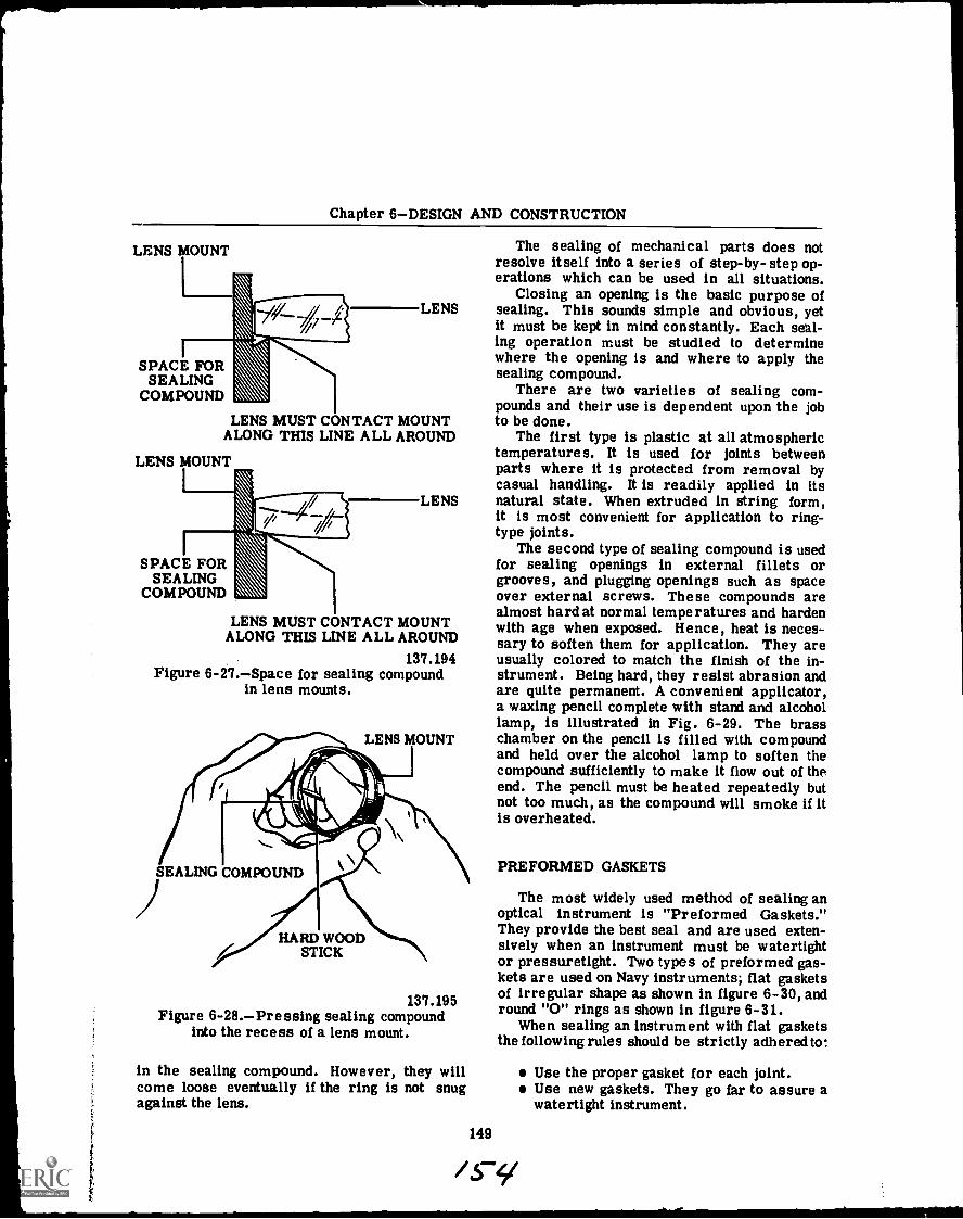
Chapter 6DESIGN AND CONSTRUCTION
LENS MOUNT
SPACE FORSEALING
COMPOUND
The sealing of mechanical parts does notresolve itself into a series of step-by-step op-erations which can be used in all situations.
Closing an opening is the basic purpose ofLENS sealing. This sounds simple and obvious, yet
it must be kept in mind constantly. Each seal-ing operation must be studied to determinewhere the opening is and where to apply thesealing compound.
There are two varieties of sealing com-pounds and their use is dependent upon the jobto be done.
The first type is plastic at all atmospherictemperatures. It is used for joints betweenparts where it is protected from removal bycasual handling. It is readily applied in its
LENS natural state. When extruded in string form,it is most convenient for application to ring-type joints.
The second type of sealing compound is usedfor sealing openings in external fillets orgrooves, and plugging openings such as spaceover external screws. These compounds arealmost hard at normal temperatures and hardenwith age when exposed. Hence, heat is neces-sary to soften them for application. They are
137.194 usually colored to match the finish of the in-Figure 6-27.Space for sealing compound strument. Being hard, they resist abrasion and
in lens mounts. are quite permanent. A convenient applicator,a waxing pencil complete with stand and alcohollamp, is illustrated in Fig. 6-29. The brasschamber on the pencil is filled with compoundand held over the alcohol lamp to soften thecompound sufficiently to make it flow out of theend. The pencil must be heated repeatedly butnot too much, as the compound will smoke if itis overheated.
LENS MUST CONTACT MOUNTALONG THIS LINE ALL AROUND
LENS MOUNT
SPACE FORSEALING
COMPOUND
LENS MUST CONTACT MOUNTALONG THIS LINE ALL AROUND
LENS MOUNT
SEALING COMPOUND
HARD WOODSTICK
137.195Figure 6-28.Pressing sealing compound
into the recess of a lens mount.
in the sealing compound. However, they willcome loose eventually if the ring is not snugagainst the lens.
149
PREFORMED GASKETS
The most widely used method of sealing anoptical instrument is "Preformed Gaskets."They provide the best seal and are used exten-sively when an instrument must be watertightor pressuretight. Two types of preformed gas-kets are used on Navy instruments; flat gasketsof irregular shape as shown in figure 6-30, andround "0" rings as shown in figure 6-31.
When sealing an instrument with flat gasketsthe following rules should be strictly adhered to
Use the proper gasket for each joint.Use new gaskets. They go far to assure awatertight instrument.
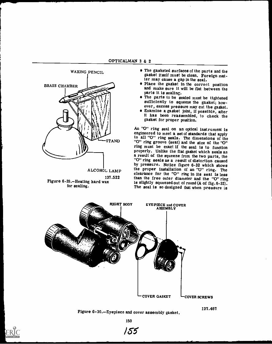
OPTICALMAN 3 & 2
WAXING PENCIL
BRASS CHAMBER
The gasketed surfaces of the parts and thegasket itself must be clean. Foreign mat-ter may cause a gap in the seal.Place the gasket in the correct positionand make sure it will be flat between theparts it is sealing.The parts to be sealed must be tightenedsufficiently to squeeze the gasket; how-ever, excess pressure may cut the gasket.Examine a gasket joint, if possible, afterit has been reassembled, to check thegasket for proper position.
An "0" ring seal on an optical instrument isengineered to meet a set of standards that applyto all "0" ring seals. The dimensions of the'--STAND "0" ring groove (seat) and the size of the "0"ring must be exact if the seal is to functionproperly. Unlike the flat gasket which seals asa result of the squeeze from the two parts, the"0" ring seals as a result of distortion causedby pressure. Notice figure 6-32 which showsthe proper installation of an "0" ring. Theclearance for the "0" ring in its seat is less
137.522 than the free outer diameter and the "0" ringFigure 6-29.Heating hard wax is slightly squeezed out of round (A of fig.6-32).for sealing. The seal is so designed that when pressure is
ALCOHOL LAMP
RIGHT BODY EYEPIECE and COVERASSEMBLY
COVER GASKET COVER SCREWS
137.467Figure 6-30.Eyepiece and cover assembly gasket.
150
135

Chapter 6DESIGN AND CONSTRUCTION
EYEPIECE"0" RING
MOUNT
RIGHTCOVER
EYEPIECELENS MOUNT
EYEPIECE"0" RING
applied to the "0" ring it moves away from thepressure into the path of leakage, thus, com-pletely sealing the passage. (B of fig. 6-32).
All 0-rings are molded and trimmed to ex-tremely close tolerances in cross-sectionalarea, inside diameter, and outside diameter.The 0-ring is generally fitted into a rectangulargroove machined in the mechanism to besealed.
The greater the pressure applied, the tighterthe seal becomes. When the pressure is de-creased, the resiliency and elasticity of theseal results in the 0-ring returning to itsnatural shape.
The first step in replacing an 0-ring is toidentify it both as to size and material. Thesize is indicated by a dash number, which alwaysfollows the part number of the 0-ring. Forexample, in the part number MS28778-6, the -6indicates the size.
After determining that the replacement sealis made of the correct material and is of theproper size, the seal should be inspected visuallyfor cuts, nicks, or flaws and discarded if anydefects appear.
When installing an 0-ring, use extreme careto prevent scratching or cutting the seal onthreads or sharp corners. Also make certainthat it is not installed in a twistedgondition, forit will not function correctly if twisted.
Individuals working with optical systemsmust be able to positively identify, inspect, andinstall the correct size and type 0-ring forevery application in order to insure the bestpossible service.
The task of procuringand positively identify-ing the correct seal can be difficult since partnumbers cannot be put directly on the seals.This situation is further confused by the factthat there is a continual introduction of new
137.523 types of seals and the obsolescence of others.Because of the difficulties with color coding,
0-rings are made available in individual her-metically sealed envelopes, labeled with allpertinent data. It is recommended that they beprocured and stocked in these envelopes.
When selecting an 0-ring for installation,information printed on the envelope should becarefully observed. If an 0-ring cannot bepositively identified, if should be discarded.
Almost all kinds of 0-rings are similar inappearance and texture, but their characteris-tics may differ widely. Here again the basic
137.524 part number on the package label provides themost reliable identification.
Figure 6-31.Eyepiece "0" ring seal.
(A) (B)
Figure 6-32.Properly installed 0-ring.
151
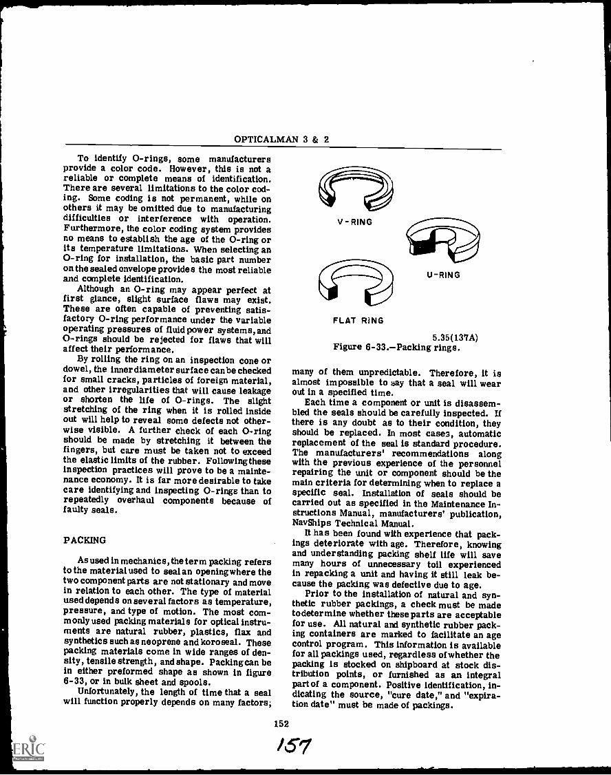
OPTICALMAN 3 & 2
To identify 0-rings, some manufacturersprovide a color code. However, this is not areliable or complete means of identification.There are several limitations to the color cod-ing. Some coding is not permanent, while onothers it may be omitted due to manufacturingdifficulties or interference with operation.Furthermore, the color coding system providesno means to establish the age of the 0-ring orits temperature limitations. When selecting an0-ring for installation, the basic part numberon the sealed envelope provides the most reliableand complete identification.
Although an 0-ring may appear perfect atfirst glance, slight surface flaws may exist.These are often capable of preventing satis-factory 0-ring performance under the variableoperating pressures of fluid power systems, and0-rings should be rejected for flaws that willaffect their performance.
By rolling the ring on an inspection cone ordowel, the inner diameter surface can be checkedfor small cracks, particles of foreign material,and other irregularities that will cause leakageor shorten the life of 0-rings. The slightstretching of the ring when it is rolled insideout will help to reveal some defects not other-wise visible. A further check of each 0-ringshould be made by stretching it between thefingers, but care must be taken not to exceedthe elastic limits of the rubber. Following theseinspection practices will prove to be a mainte-nance economy. It is far more desirable to takecare identifying and inspecting 0-rings than torepeatedly overhaul components because offaulty seals.
PACKING
As used in mechanics, the term packing refersto the material used to seal an opening where thetwo component parts are not stationary and movein relation to each other. The type of materialused depends on several factors as temperature,pressure, and type of motion. The most com-monly used packing materials for optical instru-ments are natural rubber, plastics, flax andsynthetics such as neoprene and koroseal. Thesepacking materials come in wide ranges of den-sity, tensile strength, and shape. Packing can bein either preformed shape as shown in figure6-33, or in bulk sheet and spools.
Unfortunately, the length of time that a sealwill function properly depends on many factors;
V-RING
FLAT RING
U-RING
5.35(137A)Figure 6-33.Packing rings.
many of them unpredictable. Therefore, it isalmost impossible to say that a seal will wearout in a specified time.
Each time a component or unit is disassem-bled the seals should be carefully inspected. Ifthere is any doubt as to their condition, theyshould be replaced. In most cases, automaticreplacement of the seal is standard procedure.The manufacturers' recommendations alongwith the previous experience of the personnelrepairing the unit or component should be themain criteria for determining when to replace aspecific seal. Installation of seals should becarried out as specified in the Maintenance In-structions Manual, manufacturers' publication,Nav Ships Technical Manual.
It has been found with experience that pack-ings deteriorate with age. Therefore, knowingand understanding packing shelf life will savemany hours of unnecessary toil experiencedin repacking a unit and having it still leak be-cause the packing was defective due to age.
Prior to the installation of natural and syn-thetic rubber packings, a check must be madeto determine whether these parts are acceptablefor use. All natural and synthetic rubber pack-ing containers are marked to facilitate an agecontrol program. This information is availablefor all packings used, regardless of whether thepacking is stocked on shipboard at stock dis-tribution points, or furnished as an integralpart of a component. Positive identification, in-dicating the source, "cure date," and "expira-tion date" must be made of packings.
152
/51
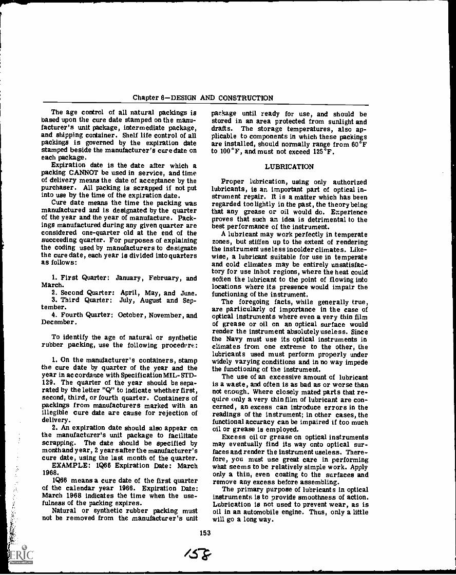
Chapter 6DESIGN AND CONSTRUCTION
The age control of all natural packings isbased upon the cure date stamped on the manu-facturer's unit package, intermediate package,and shipping container. Shelf life control of allpackings is governed by the expiration datestamped beside the manufacturer's cure date oneach package.
Expiration date is the date after which apacking CANNOT be used in service, and timeof delivery means the date of acceptance by thepurchaser. All packing is scrapped if not putinto use by the time of the expiration date.
Cure date means the time the packing wasmanufactured and is designated by the quarterof the year and the year of manufacture. Pack-ings manufactured during any given quarter areconsidered one-quarter old at the end of thesucceeding quarter. For purposes of explainingthe coding used by manufacturers to designatethe cure date, each year is divided into quartersas follows:
1. First Quarter:March.
2. Second Quarter:3. Third Quarter:
tember.4. Fourth Quarter:
December.
January, February, and
April, May, and June.July, August and Sep-
October, November, and
To identify the age of natural or syntheticrubber packing, use the following procedcrt:
1. On the manufacturer's containers, stampthe cure date by quarter of the year and theyear in accordance with Specification MIL- STD-129. The quarter of the year should be sepa-rated by the letter "Q" to indicate whether first,second, third, or fourth quarter. Containers ofpackings from manufacturers marked with anillegible cure date are cause for rejection ofdelivery.
2. An expiration date should also appear onthe manufacturer's unit package to facilitatescrapping. The date should be specified bymonth and year, 2 years after the manufacturer'scure date, using the last month of the quarter.
EXAMPLE: 1Q66 Expiration Date: March1968.
1Q66 means a cure date of the first quarterof the calendar year 1966. Expiration Date:March 1968 indicates the time when the use-fulness of the packing expires.
Natural or synthetic rubber packing mustnot be removed from the manufacturer's unit
package until ready for use, and should bestored in an area protected from sunlight anddrafts. The storage temperatures, also ap-plicable to components in which these packingsare installed, should normally range from 60°Fto 100°F, and must not exceed 125°F.
LUBRICATION
Proper lubrication, using only authorizedlubricants, is an important part of optical in-strument repair. It is a matter which has beenregarded too lightly in the past, the theory beingthat any grease or oil would do. E::perienceproves that such an idea is detrimental to thebest performance of the instrument.
A lubricant may work perfectly in temperatezones, but stiffen up to the extent of renderingthe instrument useless incolder climates. Like-wise, a lubricant suitable for use in temperateand cold climates may be entirely unsatisfac-tory for use in hot regions, where the heat couldsoften the lubricant to the point of flowing intolocations where its presence would impair thefunctioning of the instrument.
The foregoing facts, while generally true,are particularly of importance in the case ofoptical instruments where even a very thin filmof grease or oil on an optical surface wouldrender the instrument absolutely useless. Sincethe Navy must use its optical instruments inclimates from one extreme to the other, thelubricants used must perform properly underwidely varying conditions and in no way impedethe functioning of the instrument.
The use of an excessive amount of lubricantis a waste, and often is as bad as or worse thannot enough. Where closely mated parts that re-quire only a very thin film of lubricant are con-cerned, an excess can introduce errors in thereadings of the instrument; in other cases, thefunctional accuracy can be impaired if too muchoil or grease is employed.
Excess oil or grease on optical instrumentsmay eventually find its way onto optical sur-faces and render the instrument useless. There-fore, you must use great care in performingwhat seems to be relatively simple work. Applyonly a thin, even coating to the surfaces andremove any excess before assembling.
The primary purpose of lubricants in opticalinstruments is to provide smoothness of action.Lubrication is not used to prevent wear, as isoil in an automobile engine. Thus, only a littlewill go a long way.
153
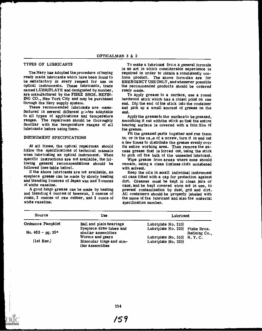
OPTICALMAN 3 & 2
TYPES OF LUBRICANTS
The Navy has adopted the procedure of buyingready made lubricants which have been found tobe satisfactory in every respect for use onoptical instruments. These lubricants, tradenamed LUBRIPLATE and designated by number,are manufactured by the FISKE BROS. REFIN-ING CO., New York City and may be purchasedthrough the Navy supply system.
These recommended lubricants are manu-factured in several different gr.ntins adaptableto all types of applications and temperatureranges. The repairman should be thoroughlyfamiliar with the temperature ranges of alllubricants before using them.
INSTRUMENT SPECIFICATIONS
At all times, the optical repairman shouldfollow the specifications of technical manualswhen lubricating an optical instrument. Whenspecific instructions are not available, the fol-lowing general recommendations should befollowed (see table below).
If the above lubricants are not available, aneyepiece grease can be made by slowly heatingand blending 5 ounces of Japan wax and 5 ouncesof white vaseline.
A good hinge grease can be made by heatingand blending 4 ounces of beeswax, 2 ounces ofrosin, 2 ounces of raw rubber, and 1 ounce ofwhite vaseline.
To make a lubricant fro:n a general formulais an art in which considerable experience isrequired in order to obtain a consistently uni-form product. The above formulas are forEMERGENCY USE ONLY, and whenever possiblethe recommended products should be orderedready made.
To apply grease to a surface, use a roundhardwood stick which has a chisel point on oneend. Dip the end of the stick into the containerand pick up a small amount of grease on theend.
Apply the grease to the surface to be greased,smoothing it out with the stick so that the entirebearing surface is covered with a thin film ofthe grease.
Fit the greased parts together and run themin; or in the came of a screw, turn it in and outa few times to distribute the grease evenly overits entire working area. Then remove the ex-cess grease that is forced out, using the stickto pick off the bulk of the unneeded lubricant.
Wipe grease from areas where none shouldremain, using a clean lintless cloth moistenedwith solvent.
Keep the oils in small individual instrumentoil cans fitted with a cap for protection againstdirt. Greases must be kept in clean jars orcans, and be kept covered when not in use, toprevent contamination by dust, grit and dirt.All containers should be properly labeled withthe name of the lubricant and also the materialspecification number.
Source Use Lubricant
Ordnance Pamphlet
No. 463 - pg. 35*
(1st Rev.)
Ball and plain bearingsEyepiece draw tubes andsimilar assembliesWorms and gearsBinocular hinge and sim-ilar assemblies
154
/59
Lubriplate No. 210)Lubriplate No. 220) Fiske Bros.
Refining Co.,Lubriplate No. 310) N. Y. C.Lubriplate No. 320)
CHAPTER 7
MAINTENANCE PROCEDURES-PART I
This chapter will provide you with informa-tion on repair and maintenance of optical in-struments. It will also stress the importanceof careful handling and cleanliness of, not onlythe instruments, but, also, the tools that youwork with.
Optical instruments are expensive precision -built instruments and care in maintaining themcannot be overemphasized. If you handle an in-strument roughly or drop it, the shock may re-sult in misalignment or breakage of the opticaland mechanical parts. When this happens, youhave only one choiceREPAIR. This meansthat you must unseal the instrument, disassem-ble it, make repairs, reassembly and collimate.This is a. lot of work caused by thoughtlessnessand negligence in handling.
Optical instruments are shipped in speciallyconstructed containers designed for adequateprotection during transportation. When you re-ceive optical instruments in the optical shop,check their containers for damage and cleanli-ness; then, if there is no reason why you shouldremove the instruments from the containers,stow them in clean storage cabinets or spacesprovided for them. CAUTION: When you MUSTMOVE AN INSTRUMENT from one location toanother, if possible, move it in its container.
Most containers for optical instruments havecatches or locks for securing the instrumentsin position; so when you put an instrument inits container, place it GENTLY INTO POSI-TION and carefully close the lid. DO NOTTRY TO FORCE AN INSTRUMENT INTO ITSCONTAINER OR SLAM THE COVER SHUT.The contour of the interior of the case wasmade in the best manner possible by the manu-facturer to hold the instrument snugly in placeto prevent damage during handling. If the in-strument does not go into its case without dif-ficulty, check for an extended drawtube orsomething else which is hindering smooth en-trance into proper position. CAUTION: Alwayssecure the cover to the container with thecatches installed by the manufacturer.
INSPECTION AND TESTING
The duties of an opticalman will always callfor him to inspect and test optical instruments.The inspection may be held aboard ship beforethe instrument is delivered to the shop or itmay be held by the repairman just before hebegins the repair work. In any case, the in-spection and testing of an optical instrument isvital and the opticalman should have a thoroughknowledge of the instrument and procedures.
INSPECTION OF INSTRUMENTS
There may be occasions when you will begiven full responsibility for inspecting all opti-cal instruments aboard a ship. By carefullyinspecting the instruments and taking care oflittle troubles, you will be able to save yourselfand your repair activity much work. Makenotes on your inspection of each instrument andrecommend appropriate remedial action, aboardyour ship or at a repair facility.
CAUTION: When you inspect an optical in-strument in use aboard ship and follow up withminor repairs, do NOT DISTURB the opticalsystem unless it is required.
When you are assigned duty in a repair ac-tivity afloat or ashore, inspect every instru-ment sent to the optical shop for repairs. If aninstrument is unfamiliar to you, get all infor-mation concerning it from Ordnance Pamphlets(OP's), NavOrd publications, NavShips Man-uals, and blue prints. Never attempt to dis-assemble and repair an instrument until youfully understand it.
During your predisassembly inspection of aninstrument, try to locate difficulties. Inspectthe physical and mechanical condition of the in-strument and also its optical system. Use acasualty analysis inspection sheet and recordall your findings on it.
The defects to look for when inspecting anoptical instrument are: dents; cracks; andbreaks in the housing, mount, and bearing
OPTICALMAN 3 Pi 2
surfaces. Unless they are on a bearing sur-face, small breaks are generally not serious,but they still require immediate attention. Acrack in the housing (or a loose or broken seal),for example, soon causes condensation of mois-ture within the instrument.
Inspect assembly screws for tightness. Ifretaining rings are exposed at the end of thetube of an instrument, check them also fortightness, by applying light pressure with yourfingers.
CAUTION: Do NOT TOUCH the lens withyour fingers, and do NOT USE a retainer ringwrench to test the rings for tightness. The set-screw of the ring (or the ring itself) may besealed with shellac; and if you attempt to turnthe ring with a wrench, you may break the seal.
Take a close look at the condition of thepaint on exposed metal parts. To prevent cor-rosion, cover worn or cracked and chippedpaint with a thin film of approved oil. As soonas possible, send the instrument to the shop forrepainting.
Mechanical Condition
Carefully examine mechanical adjustingscrews, and check knob and gear mechanismsfor slack or excessive tightness. If the instru-ment moves on bearings, test them for bindingor looseness.
Try the focusing action of the eyepiece tofind out if you can focus it (in and out) withoutbinding or dragging. If binding or draggingexists, the eyepiece adapter or the drawtube iseccentric, which condition is generally causedby dropping or jarring.
Backlash in the focusing action of an eye-piece is usually caused by a loose stop or a re-tainer ring; but it may be caused by a loose keyand its screws in the spiral keyway assembly.
Check the mechanical, 0 diopter setting ofthe eyepiece to determine whether the indexmark points to 0 diopters when the eyepiecedrawtube is at mid-throw (halfway in and half-way out). The focusing action should be suchthat the index mark clears all diopter gradua-tions (plus and minus) during full travel of thedrawtube.
If the instrument has turning shafts (ray fil-ter or input), check them by turning the shafts.If rotational action of the ray filter shafts doesnot turn the color filters in or out of the line ofsight, the cause is most likely improper meshing
of gears, or detachment of the gear itself fromthe shaft. If the shaft does not rotate, it iscorroded or bent.
All mechanisms must move freely, withoutbinding, slack, backlash, or lost motion. Mov-ing parts should be just tight enough to keepthem in proper position.
Check for missing or broken partsretainerrings, set screws, and so forth. You can locateloose or broken internal parts by shaking theinstrument.
If the instrument is gas sealed, CHECK ITSGAS PRESSURE by attaching a pressure gageto the gas inlet fitting. Then crack the valvescrew and read the pressure on the gage to findout if it is correct. Correct pressure in mostnitrogen-chamed optical instruments is ap-proximately two pounds per square inch, or asindicated in the manufacturer's technical man-ual for a particular instrument. If the gage in-dicates NO PRESSURE in the instrument, thereis a bad gasket ,a loose fitting, or a loose screw.Check for all of these defects when you dis-assemble a gas-filled optical instrument.
Optical System
Because optical elements constitute theHEART of an optical instrument, inspection ofthe optical system is very important and youshould learn to do this phase of your workwell. When you first examine an optical sys-tem, you may have difficulty in distinguishingone element from another. Through adequateexperience, however, you will be able to makethis distinction; and you will know where eachelement belongs in the system and when it isdefective.
The best method to follow in inspecting theoptical system of an instrument is to point ittoward an illuminated area and look for thefollowing:
1. DIRT AND DUST. Dirt and dust show upas dark spots (specks) on the surface of an op-tical element.
2. CHIPS, SCRATCHES, BREAKS. Thesedefects in an optical element show up as bright,Aar-like specks, scratches, or areas, whenlight is reflected from them.
3. GREASE OR OIL. Grease or oil on anoptical element in a system is indicated bystreaked, clouded, or nebulous areas, with anoccasional bright, translucent spot. You mayeven be able to detect the color by knowing thecolor of the grease used on the instrument.
156
/Go
Chapter '7MAINTENANCE PROCEDURESPART I
4. MOISTURE. Moisture shows up as asharply defined nebulous area, with brilliantreflection or a diffused, clouded appearancewhen the area is not illuminated.
5. r UNGUS OR WATER MARKS. Brown orgreen patches, or stains, indicate the presenceof Y .ngus or water marks. Deposits of salt mayeat-- a grainy, milky color similar to that of
glass.i. DETERIORATED BALSAM. Deteriora-
tic,n of Canaua balsam used to cement lensestogether is indicated by cracking, or a dark oryellow color; and areas between the elementsa.opear milky, colored or opaque, splotched, or
or thread-like. When the cement just be-Ins to separate, bubbles and areas of splotches
s'iaped like oak leaves appear between the ele-ments If there are brightly colored bands orring, (Newton's Rings) between the eletr.entq,the :.,arses arc; under strain in their mounts, ora suLttien, si-tarp Mew on the instrument ed. !Lthe cement is brml: down.
7. HAZY OR CLJUDED IMAGE. Foreignmatter on the objective lens the erectors, orthe prism::. a' an optical stem ^ause a hazyor clouded image.
You can examine color filters in an opticalsystem, provided they are within the focallength of the eyepLece, by holding e..te eye -a fewinches from Hi::: ,yepiece and t ...r.a.ng the rayfilter shaft. Defects on a filter show up when itrotates in and out t..f the hne of -.2i.g-ht.
If the field of view (true field) is not per-fectly round, there is a loose diaphragm withinthe instrument or the color filter plate is notproperly engaged with the detent ball or roller.
Check the anti-reflectioi, (magnesium fluo-ride) coating on coated optics by holding theinstrument under a daylight fluorescent lamp(white light). If the coating is of proper thick-ness on the optic, its color is light-reddishpurple. If the coating shows signs of wear(too thin), it is pale-yellow, straw, copper, orreddish-brown in color.
If the coating on a lens is too thin, the bestthing to do is replace the lens. The coatingmust be of adequate thickness in order for thelens (coating) to reduce reflection properly. Ifthe coating is of satisfactory thickness andcolor, but has scratches, the lens is still us-able; for a few scratches do not cause notice-able loss of light.
Optical elements (reticles and collectivelenses) placed in or hear image planes of aninstrument are not coated, because scratches
on them, or deterioration of the coating, appearto be superimposed on the image in the field ofview. Optical surfaces cemented to other opticalsurfaces are not coated, as is true for the con-cave and convex surfaces of a cemented doublet.Cement will NOT adhere to coated surfaces.
Reflecting surfaces of prisms which use theprinciple of the critical angle and total reflec-tion are NOT coated, for the coating causes toomuch loss of light.
Inspect prisms and mirrors for signs ofwear, peeling, or darkening of the silvered oraluminum surfaces. All of these defects showup nq blisters and cracking of the coat.' ng or ayellowish color.
Some optical defects are illustrated in partsA through K of illustration '7-1. If available,get some lenses Ith the defects shown andstudy tivrn you read the following discussionof vaous lens defects.
CHIP. A chip (part A, fig. '7-1) is a break atthe edge of a lens or prism caused by unet, enpressures or burrs on the lens seats oi thelens mounts.
NOTCH. A notch (part B, fig. 7-1) aground oft rface of a chip on a lens or prim noutside tre free aperture. A notch, however,cannot be considered a defect in the true senseof the word, because an optical repairman(Opticalman) must place it in the position indi-cated in order to prevent internal reflections.
SCRATCH AND STRIPE. A scratch (part C,fig. '7-1) remains visible as you rotate a lensor prism through 360 degreel; a stripe, on the°ther hand, vanishes at some position as yourotate the optical element. You can most easilysee scratches and stripes in optical elementswhen you place the elements against a darkbackground.
RING. A ring (pax: D, fig. 7-! ., is a cir-cular scratch or stripe around t ,e externaledges of a lens, and it is caused by pressureagainst the lens by the mount sea. s and the re-l.tiner ring. An INTERNAL RING between thee;r1rents of the lens may appear at the edges ofthe lulls when 1:.!tt.s "leaning fluid dissolves theCanada Balsat.
CRACK. A crack (part E, fig. '7-1) is gen-e :Ally caused by a sudden change of tempera-ture, resulting in sudden contraction or ex-pansion of the outer surface of the glass andfracture of the lens or prism because the cen-ter of the opt oral element does not expand orcontract at- rapidly as its edge section, whichis thicker in convex lenses and some prisms.
157
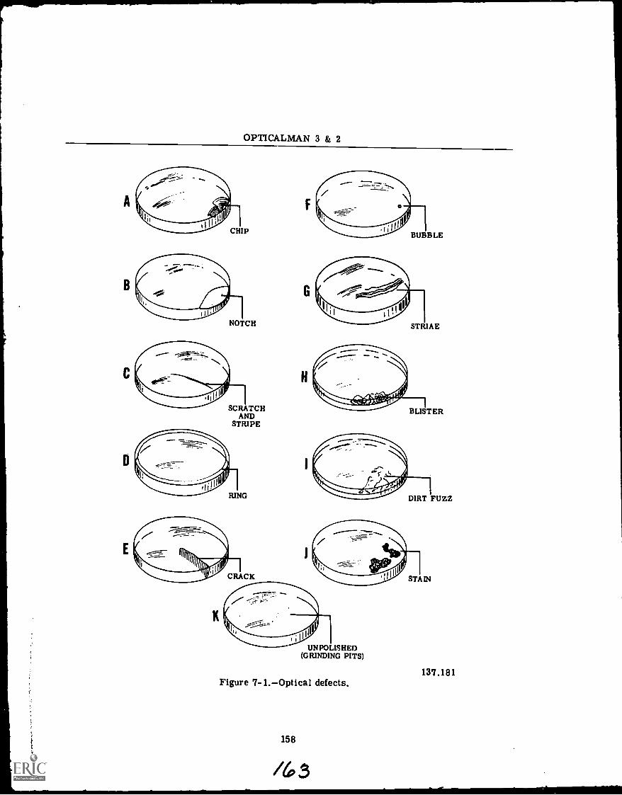
OPTICALMAN 3 & 2
SCRATCHAND
STRIPE
UNPOLISHED(GRINDING PITS)
137.181Figure 7-1.Optical defects.
158
/63
Chapter 7MAINTENANCE PROCEDURESPART I
BUBBLE. A bubble (part F, fig. 7-1) mayresult from gases left in the glass during man-ufacture, or from air which did not escapefrom the cement when the elements were joinedwith it.
STRIAE. Striae (part G, fig. 7-1) look likeveins or cords running through the glass, andyou can see them by looking through the glassat a contrasting light and dark background.This is a manufacturing defect in the opticalelement.
BLISTER. A blister (part H, fig. 7-1) is anair bubble trapped in the layer of cement be-tween two lenses. If it extends toward the cen-ter of the lens, it is called a RUN-IN, generallyproduced by the dissolving action of a cleaningfluid. A blister, however, may result from un-even mounting during assembly in the instru-ment, or by dirt between cemented lenses.Blisters can be seen best by reflected light,and they usually increase in size over a periodof time.
DIRT FUZZ. Lint, dust, or dirt (part I,fig. 7-1) in the layer of cement between lensesmay eventually cause a blister. You can seethis type of foreign matter in a lens mosteasily by transmitted light against a dark back-ground. Dirt fuzz is a manufacturing defect ina lens.
STAIN. A stain (part J, fig. 7-1) is usuallybrown or green in color and is produced by theevaporation of water or moisture which gets onlenses or prisms and dissolves some of theanti-reflecting coating, thereby causing a veryfaint deposit (sometimes bacterial in growth).
UNPOLISHED CONDITION. An unpolishedstate or condition of a glass optic (part K,fig. 7-1) results from the manufacturer's fail-ure to remove grinding pits from it. In someinstances, however, this condition is producedon optical surfaces exposed to gases, grit, andparticles of all sorts in the atmosphere.
The last step in checking the optical systemof an instrument is TESTING FOR PARALLAX,or COLLIMATION of the instrument. Alwayscheck the collimation of an instrument beforeyou disassemble it, for the information youthus procure will help you during the making ofyour casualty analysis.
You can check the collimation of an opticalinstrument in two ways: (1) by looking throughthe instrument at an infinity target, or (2) bychecking it more accurately with an auxiliarytelescope. The first method, however, is gen-erally used when quick results are necessary.
Focus the instrument on a distant target andcheck for parallax by moving the eye from sideto side and up and down. If parallax is present,the reticle (crossline) appears slightly out offocus and seems to move back and forth, up anddown, over the target. If parallax is not pres-ent, the reticle is in sharp focus with the targetand remains superimposed in one spot on thetarget, regardless of the direction in which youmove your eye behind the eyepiece.
Hold the instrument up to your eye in theposition in which it is normally used and lookat the horizontal wire of the reticle to deter-mine whether it is parallel with the horizon, orsquare in appearance. The only manner inwhich you can make an accurate check of theSQUARENESS of the crossline, however, iswith a collimator and an auxiliary telescope.
To check the eyepiece diopter setting, focusthe instrument on an infinity target and observethe position of the index mark on the diopterscale. If the index mark is not pointing to yourpersonal diopter setting, the 0 diopter is in-correct. At this point, you can determine thenumber of diopters from the 0 setting yourPERSONAL DIOPTER SETTING is off.
If the index mark points to three graduationspast your personal setting, for example, theeyepiece diopter setting is off three dioptersfrom 0 diopter to the minus side, provided youfocused from plus to minus on the scale. If theindex mark points to your personal diopter set-ting on the diopter scale, the instrument is op-tically set to 0 diopters, even though the indexmark is NOT pointing to 0 diopters.
If the instrument has a porro prism erectingsystem, check the optical system for LEAN bylooking through the instrument with one eye ata vertical target (flag pole or side of building)and by looking directly at the target with theother eye. If the two images are not PER-FECTLY parallel, there is leaning (termedLEAN) in the optical system; that is, the imagethrough the instrument appears to LEAN awayfrom the image observed with the naked eye.The reason for this LEAN is that the frostedsides of one porro prism are not at a 90° anglewith the frosted sides of the other porro prism.
TESTING OF INSTRUMENTS
Image fidelity is the FAITHFULNESS ANDSHARPNESS OF AN IMAGE VIEWED WITHAN OPTICAL INSTRUMENT. As you know,good performance of an optical instrument is

1
OPTICALMAN 3 & 2
obtained only when the images it creates arefree of aberrations and distortions.
You can make a rough test of image fidelityin a telescope, or a similar instrument, bydoing the following:
1. Find and measure the greatest distanceat which you can read clearly a newspaperheadline, or any print of comparable size.
2. Multiply the distance measured by themagnification of the instrument you are testing.
3. Mount the print at the distance you calcu-lated in item 2 and observe it through the tele-scope. If it is now just as clear and readableas it was with your naked eyes at the closerdistance, THE IMAGE IS SHARP (IMAGE FI-DELITY IS GOOD); if the image is fuzzy,IMAGE FIDELITY OF THE INSTRUMENT ISPOOR.
You can make a more accurate test forimage fidelity by placing a small, glass globewhere you can see the reflection of the sun inits surface and focusing your telescope on thatreflection. Adjust the eyepiece as necessary tocreate a small, sharp image of the sun andmove the eyepiece in or out from the setting.When you do this, you can see a number ofrings around the sun's image. If these ringsare circular and concentric, IMAGE FIDELITY(SHARPNESS) OF THE INSTRUMENT IS PER-FECT. Any distortion of the rings indicates ALACK OF IMAGE FIDELITYthe greater thedistortion of the rings, the poorer the quality ofimage fidelity.
When you check the image fidelity of an op-tical instrument, check for two things: (1) CEN-TRAL ASTIGMATISM, and (2) CENTRAL RES-OLUTION. Optical performance is basically afunction of design of the instrument and cannotbe vari'ad unless the characteristics of the opti-cal elements are changed. There are severalpossible service defects, however, WHICH CANCHANGE THE OPTICAL QUALITIES OF ONEOR MORE ELEMENTS. An optical elementunder strain by mechanical parts, for example,or tilted anr. improperly positioned elements(faulty mounting), badly matched recementedoptics, and even wrong optical parts all causepoor image fidelity.
Tests for central astigmatism and centralresolution provide an overall check of bothbasic optical performance and service defects.
A test for central astigmatism is made ONTHE AXIS of the optical system with the testfigures in the center of the field of view, whichis zero (0) on the axis of an optical system; and
it is called CENTRAL OR AXIAL ASTIGMA-TISM to distinguish it from aberration astig-matism (OFF-AXIAL ASTIGMATISM).
Resolution (resolving power) is the ability ofan optical system to distinguish details in anobject; so it is therefore a very importantcharacteristic of an instrument, usually statedin terms of the ANGLE SUBTENDED BY THECLOSEST POINTS ON AN OBJECT THAT THESYSTEM CAN REVEAL SEPARATED. A stricttest of the resolving power on the optical axiscentral resolutionis a good check on the over-all image fidelity.
Image Fidelity
Take a close look now at illustration 7-2,which shows a standard test chart for testingimage fidelity in optical instruments. This is astandard test chart available through navalsupply channels.
160
iii3.5
NATIONAL BUREAU OF STANDARDSTEST CHART 1 25 X
137.182Figure 7-2.Image fidelity
test chart.
The 56-line-per-inch group at the top of theimage fidelity test chart is used for testingcentral resolution of 7 x 50 binoculars andMark 1, Mod 0, ship's telescopes. The 28-line-per-inch group is used for testing central astig-matism in these instruments. You can make upa separate chart for each required line spacingby cutting out the groups of lines from twostandard charts (fig. 7-2) and pasting them on awhite background.
/66
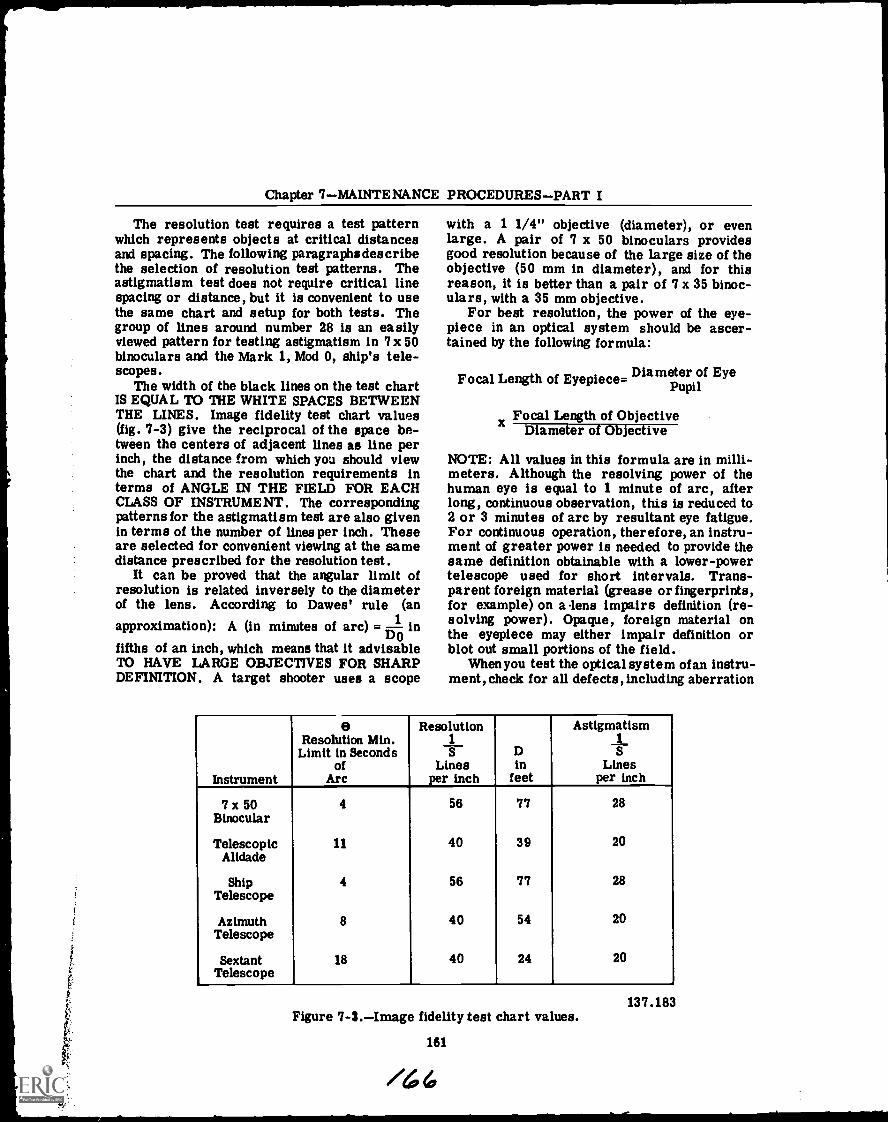
Chapter 7MAINTENANCE PROCEDURESPART I
The resolution test requires a test patternwhich represents objects at critical distancesand spacing. The following paragraphsdescribethe selection of resolution test patterns. Theastigmatism test does not require critical linespacing or distance, but it is convenient to usethe same chart and setup for both tests. Thegroup of lines around number 28 is an easilyviewed pattern for testing astigmatism in 7x 50binoculars and the Mark 1, Mod 0, ship's tele-scopes.
The width of the black lines on the test chartIS EQUAL TO THE WHITE SPACES BETWEENTHE LINES. Image fidelity test chart values(fig. 7-3) give the reciprocal of the space be-tween the centers of adjacent lines as line perinch, the distance from which you should viewthe chart and the resolution requirements interms of ANGLE IN THE FIELD FOR EACHCLASS OF INSTRUMENT. The correspondingpatterns for the astigmatism test are also givenin terms of the number of lines per inch. Theseare selected for convenient viewing at the samedistance prescribed for the resolution test.
It can be proved that the angular limit ofresolution is related inversely to the diameterof the lens. According to Dawes' rule (an
approximation): A (in minutes of arc) = 1 inDo
fifths of an inch, which means that it advisableTO HAVE LARGE OBJECTIVES FOR SHARPDEFINITION. A target shooter uses a scope
with a 1 1/4" objective (diameter), or evenlarge. A pair of 7 x 50 binoculars providesgood resolution because of the large size of theobjective (50 mm in diameter), and for thisreason, it is better than a pair of 7 x 35 binoc-ulars, with a 35 mm objective.
For best resolution, the power of the eye-piece in an optical system should be ascer-tained by the following formula:
Focal Length of Eyepiece= Diameter of EyePupil
Focal Length of ObjectiveDiameter of Objective
NOTE: All values in this formula are in milli-meters. Although the resolving power of thehuman eye is equal to 1 minute of arc, afterlong, continuous observation, this is reduced to2 or 3 minutes of arc by resultant eye fatigue.For continuous operation, therefore, an instru-ment of greater power is needed to provide thesame definition obtainable with a lower-powertelescope used for short intervals. Trans-parent foreign material (grease or fingerprints,for example) on a lens impairs definition (re-solving power). Opaque, foreign material onthe eyepiece may either impair definition orblot out small portions of the field.
When you test the optical system of an instru-ment, check for all defects, including aberration
Instrument
eResolution Min.
Limit in Secondsof
Arc
Resolution1S
Linesper inch
Din
feet
Astigmatism1
SLines
per inch
7 x 50
_
4 56 77 28Binocular
Telescopic 11 40 39 20Alidade
Ship 4 56 77 28Telescope
Azimuth 8 40 54 20Telescope
Sextant 18 40 24 20Telescope
Figure 7-3.Image fidelity test chart values.
161
/6
137.183
OPTICALMAN 3 & 2
(all types), coma, astigmatism, flatness offield, and distortion. All of these defects,singly or in combination, can affect the qualityof image formed by an optical instrument; oreven render the instrument useless.
The procedure for testing an optical instru-ment for astigmatism follows.
1. Use the proper test chart and set it at thedistance given in the listing of values. Sightthe test pattern for astigmatism on the chartwith the instrument to be tested, and line up thecenter of the astigmatism pattern in the centerof the field of view.
2. Place an auxiliary telescope to the eye-piece of the instrument undergoing the test andadjust it to bring the horizontal set of linesinto sharp focus. Note the diopter reading onthe auxiliary telescope. CAUTION: The focus-ing adjustment of the primary instrument (oneundergoing the test) must NOT BE CHANGEDafter you perform the preceding operation.
3. Check the vertical set of lines for focus.If it is not sharp, ASTIGMATISM IS PRESENT.To put the vertical set of lines in sharp focus,adjust the auxiliary telescope diopter ring.OBSERVE THE DIOPTER READING.
4. The maximum allowable difference indiopters between the horizontal and verticallines is 0.15 diopters for the primary instru-ment being tested. Divide the diopter differ-ence found in the auxiliary telescope, steps 2and 3, by the square of its power to arrive atthe corresponding change that would be found inthe primary instrument without the auxiliarytelescope. For example, the diopter change inthe primary instrument equals:
Diopter Change in Auxiliary Telescope (DCA)
(Power of Auxiliary Telescope) 2
As you can see, the auxiliary telescope in-creases the sensitivity of the test BY THESQUARE OF ITS POWER. The maximum al-lowable diopter difference for typical auxiliarytelescopes is as follows:
Power of Maximum AllowableAuxiliary Telescope Diopter Difference
3 1.354 2.405 3.756 5.40
5. If the horizontal and vertical lines are infocus within the allowable tolerance, repeat
steps 2 and 3 for the diagonal sets of lines.The same tolerance prevails.
NOTE : Excessive astigmatism may be causedby a defective or poorly mounted lens. Checkthe objective lens first, and then the reflectingsurfaces of the prisms (objective prism first).These surfaces must be optically flat to closetolerances .
If the instrument you are testing passes theastigmatism test, keep the test setup intact anduse the following procedure to test for centralresolution:
1. Sight the proper chart at the correct dis-tance with the instrument you are testing withan auxiliary telescope and adjust the instru-ment in order TO BRING THE CENTER OFTHE RESOLUTION PATTERN INTO THE CEN-TER OF THE FIELD OF VIEW.
CAUTION: Be sure you have the patterncentered. The resolving power falls off awayfrom the optical axis. Focus on one set oflines.
Because the minimum resolving power of awell-designed instrument is finer than the eyecan observe, always use an auxiliary telescopeto mkae a test for central resolution. The in-strument is better than the eye, and the auxil-iary power reveals details to the eye.
2. When the black horizontal and verticallines on the test chart (and the other diagonalsets of lines) APPEAR SHARP AND CLEARLYSEPARATED, resolution in the instrument issatisfactory.
Poor resolution is caused by defective ob-jective lenses and prisms. Always replace theobjective lens first. Misplaced, unmatched,and shifted prisms cause trouble because theydisplace the line of sight. A bad reflecting faceon a prism also causes poor resolution.
To check an optical instrument for flaresand ghosts, point it toward a small, brightobject against a dark background and focussharply. If you observe rings or streaks oflight, or one or more faint GHOST IMAGES,the image HAS EXCESSIVE INTERNAL RE-FLECTION. Flares and ghosts in an instru-ment INDICATE A PROBABLE NEED FORRE COATING OF LENSES.
ILLUMINATION AND CONTRAST
Illumination of an image depends upon theamount of light received by the objective andthe specific intensity (bright daylight or twi-light) of these light rays. As you know, the
162
/6 7
Chapter 7MAINTENANCE PROCEDURESPART I
amount of light received is determined by thediameter of the entrance pupil of the objective;and the amount of light which enters the eye islimited by either the exit pupil of the instru-ment or the pupil of the eye, whichever issmaller.
For maximum illumination at any given lightintensity, the exit pupil of an optical instrumentmust equal the entrance pupil of the eye underthe same conditions. With any instrument, fur-thermore, retinal illumination is never greaterthan illumination by the unaided eye. Opaqueforeign substancesdust or lint, for exampleon any optical surface (except one in a realimage plane) reduces the amount of illumina-tion in the system.
To test for illumination and contrast in anoptical instrument, focus the instrument on adistant object and check the image for bright-ness. The IMAGE SHOULD BE NEARLY ASBRIGHT AS THE OBJECT APPEARS TO THENAKED EYE . If the image is dim, the exitpupil may be too large; if the size of the exitpupil is correct (about 0.1" for bright light, to0.3" for very dim light), look for dirty, stained,or uncoated optical surfaces and darkened mir-rors or cement.
Contrast of the image produced by the in-strument should be just as good as the contrastof the object seen by the naked eye. If the imageis dull and cloudy, look for dirty, oily, or dampoptical surfaces.
Aberrations
When you test an optical instrument, checkclosely for all defects, including aberrations,coma, astigmatism, flatness of field and dis-tortion.
To test an optical instrument for sphericalaberration, cover the outer half of the objectivewith a ring of black paper, focus sharply on adistant object, and read the diopter scale. Thenremove the ring of paper and cover the innerhalf of the objective with a black disk. Refocusthe instrument and read the diopter scale again.If the amount of movement of the eyepiece forfocusing is very small, the instrument is wellcorrected for spherical aberration.
Chromatic Aberration
You can test an optical instrument for chro-matic (color) aberration by doing the following:
1. Set up a white disk against a black back-ground, far enough away to enable you to focusthe instrument sharply. When the image is infocus, IT SHOULD HAVE NO COLOR FRINGES.
2. Push the drawtube in a short distance andlook for a light-yellow fringe which should bearound the image of the disk.
3. Refocus and pull the drawtube out a shortdistance, AT WHICH POINT THE IMAGESHOULD BE FRINGED WITH PALE PURPLE .
The two colors (light-yellow and pale-purple)you got by focusing the instrument constitutethe SECONDARY SPECTRUM OF THE OPTI-CAL SYSTEM, and they show that THE SYS-TEM IS WELL CORRECTED FOR PRIMARYCHROMATIC ABERRATION (RED AND BLUE).
163
/6 7
Coma and Astigmatism
Focus the instrument sharply on a small,round, white object near the edge of the fieldand study the image produced. If the image iscircular and flareless, the INSTRUMENT ISFREE OF COMA .
NOTE: Test for coma at FIVE OR SIXDIFFERENT POINTS around the outer edge ofthe field.
An optical instrument has excessive astig-matism if one of the cross lines of the reticleshows parallax after you have eliminated par-allax for the other cross line.
Point the instrument being tested toward thehorizon and focus sharply on AN OBJECT INTHE CENTER OF THE FIELD. If the edges ofthe field are IN SHARP FOCUS, THE FIELDIS FLAT; if the edges are not IN FOCUS, RE-FOCUS THE INSTRUMENT AS NECESSARY inorder to create a sharp image of objects at theexterme edge of the field. The change youmade in the diopter setting of the eyepieceshows the amount and direction of curvature.
NOTE: If refocusing of the instrument doesnot sharpen the image of objects at the edge ofthe field, ASTIGMATISM OR COMA IS RE-SPONSIBLE.
Distortion
You can test an optical instrument for dis-tortion in the following manner:
1. Rule a pattern of vertical and horizontallines on a large sheet of cardboard and put itwhere the pattern nearly fills the field of viewof the instrument.
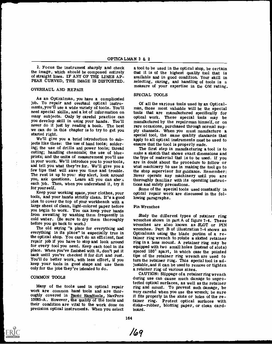
OPTICALMAN 3 & 2
2. Focus the instrument sharply and checkthe image, which should be composed entirelyof straight lines. IF ANY OF THE LINES AP-PEAR CURVED, THE IMAGE IS DISTORTED.
OVERHAUL AND REPAIR
As an Opticalman, you have a complicatedjob. To repair and overhaul optical instru-ments,you'll use a wide variety of tools. You'llneed special skills, and a lot of information onmany subjects. Only by careful practice canyou develop skill in using your hands. You'llnever do it just by reading a book. The bestwe can do in this chapter is to try to get youstarted right.
We'll give you a brief introduction to sub-jects like these: the use of hand tools; solder-ing; the use of drills and power tools; threadcutting; handling chemicals; the use of blue-prints; and the units of measurement you'll usein your work. We'll introduce you to your tools,and tell you what they're for. We'll give you afew tips that will save you time and trouble.The rest is up to you: stay alert, look aroundyou, ask questions. Learn all you can abo,.,.each job. Then, when you understand it, try itfor yourself.
Keep your working space, your clothes, yourtools, and your hands strictly clean. It's a goodidea to cover the top of your workbench with alarge sheet of clean, light-colored paper beforeyou begin to work. You can keep your handsfrom sweating by washing them frequently incold water. (Be sure to dry them thoroughlybefore you go back to work.)
The old saying "a place for everything andeverything in its place" is especially true inthe optical shop. You can't do an efficient, fastrepair job if you have to stop and look aroundfor every tool you need. Keep each tool in itsplace. When you've finished with it, don't put itback until you've checked it for dirt and rust.You'll do better work, with less effort, U youkeep your tools in good shape and use themonly for the jobs they're intended to do.
COMMON TOOLS
Many of the tools used in optical repairwork are common hand tools and are thor-oughly covered in Basic Handtools, NavPers10085-A. However, the quality of the tools andtheir condition are vital to the work done onprecision optical instruments. When you select
a tool to be used in the optical shop, be certainthat it is of the highest quality tool that isavailable and in good condition. Your skill inselecting, caring, and handling of tools is ameasure of your expertise in the OM rating.
SPECIAL TOOLS
Of all the various tools used by an Optical-man, those most valuable will be the specialtools that are manufactured specifically foroptical work. These special tools may bemanufactured by the repairman himself, or onrare occasions, purchased through normal sup-ply channels. When you must manufacture aspecial tool, the same quality standards thatapply to all optical instruments must be used toensure that the tool is properly made.
The first step in manufacturing a tool is tomake a sketch that shows exact dimensions andthe type of material that is to be used. If youare in doubt about the procedure to follow orwhat machinery to use in making the tool go tothe shop supervisor for guidance. Remember:Never operate any machinery until you arethoroughly familiar with its operating instruc-tions and safety precautions.
Some of the special tools used constantly inoptical repair work are discussed in the fol-lowing paragraphs.
Pin Wrenches
Study the different types of retainer ringwrenches shown in part A of figure 7-4. Thesewrenches are also known as SLOT or PINwrenches. Part B of illustration 7-4 shows anOpticalman using the blade portion of a re-tainer ring wrench to rotate a slotted retainerring in a lens mount. A retainer ring may beequipped with two small holes (instead of slots)spaced 180° apart, in which case the pointedtips of the retainer ring wrench are used toturn the retainer ring. This special tool is ad-justable, and it can be used to remove or tightena retainer ring of various sizes.
CAUTION: Slippage of a retainer ring wrenchduring use can cause much damage to unpro-tected optical surfaces, as well as the retainerring and mount. To prevent such damage, bevery careful when you use the wrench; be sureit fits properly in the slots or holes of the re-tainer ring. Protect optical surfaces withdisksrubber, blotting paper, or clean card-board.
164
/6q
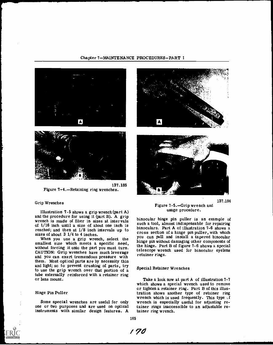
Chapter 7MAINTENANCE PROCEDURESPART I
0I;
137.185Figure 7-4.Retaining ring wrenches.
Grip Wrenches
Illustration 7-5 shows a grip wrench (part A)and the procedure for using it (part B). A gripwrench is made of fiber in sizes at intervalsof 1/16 inch until a size of about one inch isreached; and then at 1/8 inch intervals up tosizes of about 3 1/4 to 4 inches.
When you use a grip wrench, select thesmallest size which meets a specific need,without forcing it onto the part you must turn.CAUTION: Grip wrenches have much leverageand you can exert tremendous pressure withthem. Most optical parts are by necessity thinand light; so to prevent crushing of parts, tryto use the grip wrench over that portion of atube externally reinforced with a retainer ringor lens mount.
Hinge Pin Puller
Some special wrenches are useful for onlyone or two purposes and are used on opticalinstruments with similar design features. A
A
47 411101.
c'5 1.
vi
137.184Figure 7-5.Grip wrench and
usage procedure.
binocular hinge pin puller is an example ofsuch a tool, almost indispensable for repairingbinoculars. Part A of illustration 7-6 shows across section of a hinge pin puller, with whichyou can pull and install a tapered binocularhinge pin without damaging other components ofthe hinge. Part B of figure 7-6 shows a specialtelescope wrench used for binocular eyelensretainer rings.
Special Retainer Wrenches
Take a look now at part A of illustration 7-7which shows a special wrench used to removeor tighten a retainer ring. Part B of this illus-tration shows another type of retainer ringwrench which is used frequently. This type Lfwrench is especially useful for adjusting re-tainer rings inaccessible to an adjustable re-tainer ring wrench.
165
i 7d
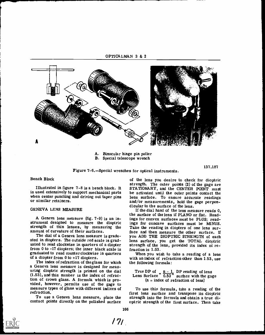
OPTICALMAN 3 & 2
A. Binocular hinge pin pullerB. Special telescope wrench
Figure 7-6.Special wrenches for optical instruments.
Bench Block
Illustrated in figure '7-8 is a bench block. Itis used extensively to support mechanical partswhen center punching and driving out taper pinsor similar retainers.
GENEVA LENS MEASURE
A Geneva lens measure (fig. '7-9) is an in-strument designed to measure the dioptricstrength of thin lenses, by measuring theamount of curvature of their surfaces.
The dial of a Geneva lens measure is gradu-ated in diopters. The outside red scale is grad-uated to read clockwise in quarters of a diopterfrom 0 to -17 diopters; the inner black scale isgraduated to read counterclockwise in quartersof a diopter from 0 to +17 diopters.
The index of refraction of the glass for whicha Geneva lens measure is designed for meas-uring dioptric strength is printed on the dial(1.53), and this number is the index of refrac-tion of crown glass. A formula which is pro-vided, however, permits use of the gage tomeasure types of glass with different indices ofrefraction.
To use a Geneva lens measure, place thecontact points directly on the polished surface
166
/7/,
137.187
of the lens you desire to check for dioptricstrength. The outer points (2) of the gage areSTATIONARY, and the CENTER POINT mustbe activated until the outer points contact thelens surface. To ensure accurate readingsand/or measurements, hold the gage perpen-dicular to the surface of the lens.
If the dial hand of the lens measure reads 0,the surface of the lens if PLANO or flat. Read-ings for convex surfaces must be PLUS; read-ings for concave surfaces must be MINUS.Take the reading in diopters of one lens sur-face and then measure the other surface. Ifyou ADD THE DIOPTRIC STRENGTH of eachlens surface, you get the TOTAL dioptricstrength of the lens, provided its index of re-fraction is 1.53.
When you wish to take a reading of a lenswith an index of refraction other than 1.53, usethe following formula:
True DP of n - l DP reading of lensLens Surface 0.53 surface with the gage
(n = index of refraction of lens)
To use this formula, take a reading of thefirst lens surface and transpose its dioptricstrength into the formula and obtain a true di-optric strength of the first surface. Then take
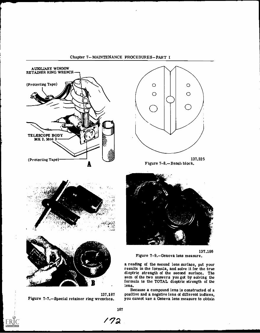
Chapter 7MAINTENANCE PROCEDURESPART I
AUXILIARY WINDOWRETAINER RING WRENCH
(Protecting Tape)
TELESCOPE BODYMK 2, Mod 3
(Protecting Tape)
,...N....
i.,
,t,4./
137.187Figure 7-7.Special retainer ring wrenches.
167
137.525Figure 7-8.Bench block.
137.186Figure 7-9.Geneva lens measure.
a reading of the second lens surface, put yourresults in the formula, and solve it for the truedioptric strength of the second surface. Thesum of the two answers you got by solving theformula is the TOTAL dioptric strength of thelens.
Because a compound lens is constructed of apositive and a negative lens of different indices,you cannot use a Geneva lens measure to obtain
OPTICALMAN 3 & 2
its dioptric strength; but if the two elements ofthe lens are separated, you can obtain the diop-tric strength of the individual elements and addboth results to get the dioptric strength of thecombination. NOTE: The lenses must be incontact and used as a unit in order to use thecorrect dioptric strength of the combination.
Remember that the dioptric strengths of thetwo lenses have opposite signs; that is, thepositive lens has a positive dioptric value andthe negative lens has a negative dioptric value.You must remember this when you add the twovalues.
Another thing to keep in mind concerning aGeneva lens measure is that it is designed tomeasure only the curvature of a lens' surfaces;so the thicker the lens, the less accurate theresults derived through its use. When you arecementing lenses together, use a Geneva lensmeasure to make certain that the positive lenssurface matches the negative lens surface.
DISASSEMBLY
Before you do any repair work on opticalinstruments, clean your work space and geteverything ready and in position. Your workingspace, your clothes, your tools, your hands,and everything should be almost immaculatebefore you begin work on an optical instrument,especially on optical elements. Cover yourworkbench with a sheet of clean, dry paper oflight color.
Clean outside metal and painted surfaceswith a clean, soft cloth (used for this purposeonly). If a solvent is required to remove greaseor foreign matter, use benzene or an approveddry cleaning solvent. Clean the outside sur-faces of objectives and eyepieces in theirmounts. Some particles of dust on an objectivedo not have a particularly harmful effect on animage produced by the objective, though they doprevent passage of light through the area they ,
cover; but a film of dust on the objective mayaffect the quality of the image and you musttherefore remove it.
If your casualty analysis indicates that theinstrument must be partially or completelydisassembled in order to effect necessary re-pairs, follow the procedure discussed next.
Procedure
When you disassemble an optical instrument,do not mix non-interchangeable parts of one
168
instrument with non-interchangeable parts ofanother instrument. In the interest of produc-tion and/or competence of performance, experi-enced optical repairmen work on more than oneinstrument at a time; and this same statementis true for many Opticalmen, especially whenall the instruments require a major overhaul.
If you must work on more than one instru-ment at a particular time, keep the parts ofeach instrument in separate containers; andlabel the parts for double safety and easy iden-tification. One of the surest and best ways tolabel parts is to scribe each metal part with anidentifying mark. When you are giving fourpairs of binoculars a general overhaul, for ex-ample, you can label the parts of the first bin-ocular #1, the parts of the second binocular #2,and so on, In order to identify satisfactorilythe parts for right and left barrels, add an R(right) or an L (left), as appropriate. Yourmarkings on the parts for the right and leftbarrels would thenbe #1R, or #3L, and so forth.Be careful to scribe these marks where theywill not be covered with paint later, and wherethey will not affect the performance of theinstrument.
Other markings which you may be requiredto make or check during disassembly are AS-SEMBLY MARKS. When a manufacturer makesan optical instrument, he fits certain parts byhand; and if there is danger of incorrect as-sembly of these parts during a later overhaul,he marks them with a small punch mark or ascribe line (on each part of an assembly). Whenyou disassemble an optical instrument, there-fore, look for these assembly marks; and ifthey are missing, make appropriate marks ofyour own. See figure 7-10, which shows theprocedure for marking a part.
Optical elements (glass) require anothermarking technique, which must meet two re-quirements: (1) the direction the optic mustface when reassembled, and (2) the function theoptic serves in the optical system.
You can identify the function of the optic bywriting on the frosted portion the following:Obj. (objective lens), #1 Er. (first erector),#2 Er. (second erector), and so on until youmark the last element in the system. The firsterector receives the light from the objectiveand should therefore be numbered first. Use asoft-lead pencil or an instant-drying markingpen.
The accepted method for determining thedirection an optical element must face in a

Chapter 7MAINTENANCE PROCEDURESPART I
MALE CENTER
MALE CENTERWASHER
ReassemblyGuide Mark
FEMALECENTER
Scribing Tool
INDEX MIRRORBASE and SCALEARM ASSEMBLY FEMALE CENTER
137.188Figure 7-10.Scribing an assembly mark.
system is to mark an arrow on the frosted edgeof a lens or prism, the tip of which indicatesthe direction of light through the instrument.
If you presume a lens in a system is facingihe wrong direction, study the diagram for thatparticular instrument (MARK and MOD) as youremove the lens. You can also use a Genevalens measure to check the readings of the lensagainst those listed on the optical diagram.
If you do not fully understand an instrumentyou must overhaul, obtain and follow a disas-sembly sheet, or follow the disassembly pro-cedure in the applicable naval publication (Nay-Ships manual; Ordnance Pamphlet, OP).
These authentic sources provide informationon troublesome areas pertaining to disassem-bly, and they also list the precautions youshould take.
CAUTION: Before you disassemble any op-tical instrument, determine whether it is apressure-tight type. If it is gas filled, releasethe gas pressure slowly by opening the gas out-let valve. Never remove anything from the in-strument until the pressure is fully released.
169
Start your disassembly of an optical instru-ment by removing exterior parts which hinderfurther disassembly, or by removing an exte-rior retainer ring, cover cap, or access plate(secured by screws). These exterior parts mayoccasionally be frozen, because they have beenexposed to the weather; that is, metal parts inclose contact become secured together as a re-sult of corrosion, electrolytic action, or naturalaffinity for each other. Aluminum-to-aluminumjoints have the greatest tendency to freeze (alsocalled seize). Salt-laden atmosphere enhancesthe tendency of metal parts of navigational in-struments to seize together ; and if the moistureseal of the instrument was unsatisfactory, salt-laden moisture will most likely be present in-side the instrument.
If this moisture is present inside the instru-ment, some of the interior parts may also befrozen.
Frozen Parts
The procedure for removing frozen partsfollows:
1. To prevent damage to parts which comeoff easily (especially optics), remove them first.
2. Use proper tools, and do not crush partswith wrenches.
3. If you could not remove a lens, cover itwith a pad of blotting paper, or a rubber disk ofthe same size.
4. When time permits, soak frozen joints inpenetrating oil.
5. Use shaped wooden blocks to hold a partin a vise. Powdered rosin on the blocks helpsto hold a part and prevent it from slipping outof position.
6. If a joint is still frozen after you havesoaked it a reasonable time in penetrating oil,proceed as follows:
a. Wipe off excess penetrating oil andapply heat to the exterior part as you turn itslowly.
b. If the part breaks free, remove theheat, apply penetrating oil, and carefully separate the parts.
c. To separate badly frozen parts whichcan be held solidly, apply penetrating oil andheat. Then apply pressure to the part in theform of an impact, not a steady pressure; forexample, put a wrench on a nut or part andstrike tile wrench (just back of the head overthe part) with a fiber mallet. This impactloosens the nut or part, as a general rule.
/ v

111111111111
OPTICALMAN 3 & 2
d. If the parts are light and springy (bodytubes and retainer rings, for example), use alight fiber mallet to tap lightly around the jointas you apply penetrating oil and heat, to helpwork the penetrating oil into the joint and workthe corrosion out.
CAUTION: Use extreme care and patiencewhen you apply heat and pressure to frozenjoints, lest you cause distortion (twisting andbending) of metal parts, and breakage of opticalelements you could not remove at the outset.
7. If frozen parts do not yield to the proce-dures just outlined, salvage the most expensivepart or parts by carefully cutting, breaking, ormachining away the other frozen parts or parts.When a retainer ring is frozen, for example,drill a hole down through it towards the lens;but use care, lest you drill too deeply and ruinthe lens with the drill. The diameter of yourdrill should be slightly less than the thicknessof the ring.
After you weaken the ring by drilling thehole, carefully bend the ring out at that pointand remove the free ring and lens. Some re-tainer rings are kept in place (made vibrationproof) by an application of shellac or a similarsubstance on the threads of the mount and tothe edge of the ring. You can soften this com-pound by repeated applications, as necessary,of acetone or alcohol.
8. To remove screws and set screws withstripped slots or heads twisted off, usuallytroublesome during disassembly, proceed asfollows:
a. If a screw is frozen in a hole as a re-sult of corrosion, loosen it with penetrating oiland heat. NOTE: Do this before you try to re-move the screw.
b. If the body of a screw protrudes abovethe surface of a part, file in a new screwdriverslot with a small swiss slotting file and removethe screw with a screwdriver of proper size.You can generally remove some protrudingscrews with parallel motion pliers.
c. If a screw is deep in a tapped hole,use a sharp scribe tip and, if possible, make anew slot in the screw. This process is slowand requires patience and care.
d. If the procedures just described do notwork, use one of the following procedures todrill the screw out:
(1) For very small screws, use adrill slightly smaller in diameter than the minordiameter of the screw and drill through thescrew. The outer shelland threads of the screw
170
still remain, and you can run a tap of correctsize through the hole to finish the job.
(2) On screws of larger size, drill ahole of proper size in the screw and remove itwith a screw extractor. (Each extractor has adrill of recommended size to use with it.)
Remember that patience and careful, intel-ligent workmanship are required in order toremove frozen parts from an optical instru-ment; but do not spend more time on an instru-ment than it is worth. Consult your shop su-pervisor whenever you are in doubt.
After you remove all frozen parts, continuewith the disassembly. Remember to mark alloptical and mechanical parts. Before you turnoff a retainer ring or try to unscrew or slide alens mount, remove the setscrews which securethem. Some of these screws may be hiddenunder sealing wax, so check for them carefully.Failtire to remove these setscrews may causea part to become seized.
Exercise extreme care when you removeoptical elements and geared assemblies throughopenings in the optical chamber. These partscan be easily damaged by striking other partsand the chamber housing. When you remove apart which exposes the interior of the opticalchamber of an instrument, make sure you tapeor close it off in some manner in order to ex-clude foreign matter.
As you remove parts and assemblies fromthe interior of an instrument, check them fordamage not previously noted and write yourfindings on your casualty analysis sheet forfuture reference.
Thus far, with few exceptions, our discus-sion of disassembly of an optical instrumenthas covered mostly mechanical parts, becausethis is the proper sequence for disassemblingthe instrument. As you disassemble an instru-ment, remove each lens mount and cell and setit aside for disassembly after you complete thedisassembly of mechanical components.
Lenses from Mounts
The techniques discussed at this point forremoving lenses from mounts are primarilyfor lenses mounted with a sealing compound,but they are also applicable for the removal ofoptics difficult to disassemble. The techniquesto follow (and precautions to use) when you dis-assemble optical elements from their mountscannot be formulated as step-by-step instruc-tions. The information and/or things which you
/75
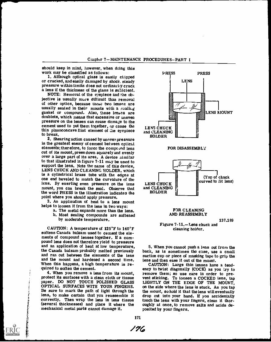
Chapter 7MAINTENANCE PROCEDURESPART I
should keep in mind, however, when doing thiswork may be classified as follows:
1. Although optical glass is easily chippedor cracked, and easily damaged by shock, steadypressure within limits does not ordinarily cracka lens if the thickness of the glass is suaicient.
NOTE: Removal of the eyepiece and the ob-jective is usually more difficult than removalof other optics, because mese two lenses areusually sealed in their mounts with a :;oalii.ggasket or compound. Also, these lenses aredoublets, which means that excessive or unevenpressure on the lenses can cause damage to thecement used to put them together, or cause thethin planoconcave flint element of eyepieceto break.
2. Shearing action caused by uneven pressureis the greatest enemy of cement between opticalelements; therefore, to force the compeand lensout of its mount, press down squarely and evenlyover a large part of its area. A device similarto that illustrated in figure 7-11 may be used tosupport the lens. Note the name of this device,LENS CHUCK AND CLEANING HOLDER, whichis a cylindrical brass tube with the edges atone end beveled to match the curvature of thelens. By exerting even pressure on the lensmount, you can break the seal. Observe thatthe word PRESS in the illustration indicates thepoint where you should apply pressure.
3. An application of heat to a lens mounthelps to loosen it from the lens in two ways:
a. The metal expands more than the lens.b. Most sealing compounds are softened
by moderate temperature.
CAUTION: A temperature of 125°F to 140°Fsoftens Canada balsam used to cement the ele-ments of compound lenses together. If a com-pound lens does not therefore yield to pressureand an application of heat at low temperature,the Canada balsam probably melted previouslyand ran out between the elements of the lensand the mount and hardened a second time.When this happens, a high temperature is re-quired to soften the cement.
4. When you remove a lens from its mount,protect its surfaces with a clean cloth or tissuepaper. DO NOT TOUCH POLISHED GLASSOPTICAL SURFACES WITH YOUR FINGERS.Be sure to mark the path of light through thelens, to make certain that you reassemble itcorrectly. Then wrap the lens in lens tissue(several thicknesses) and place it where themechanical metal parts cannot damage it.
PRESS PRESS
LENS
LENS CHUCKand CLEANING
HOLDER
LENS MOUNT
FOR DISASSEMBLY
LENS CHUCKand CLEANING
HOLDER
1(Top of chuck
curved to fit lens)
FOR CLEANINGAND REASSEMBLY
137.189Figure 7-11.Lens chuck and
cleaning holder.
5. When you cannot push a lens out from theback, as is sometimes the case, use a smallsuction cup or piece of masking tape to grip thelens and then ease it out of the mount.
CAUTION: Large thin lenses have a tend-ency to twist diagonally (COCK) as you try toremove them; so use care in order to pre-vent sticking. To loosen a COCKED lens, tapLIGHTLY ON THE EDGE OF THE MOUNT,on the side where the lens is stuck. As you tapthe mount, so hold it that the lens will eventuallydrop out into your hand. If you accidentallytouch the lens with your fingers, clean it thor-oughly at once, to remove salts and acids de-posited by your fingers.
171
/7c
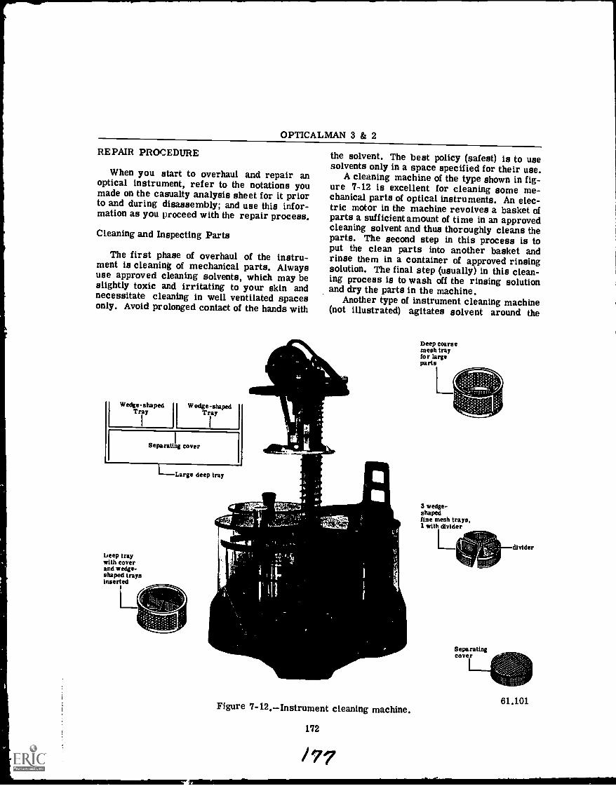
OPTICALMAN 3 & 2
REPAIR PROCEDURE
When you start to overhaul and repair anoptical instrument, refer to the notations youmade on the casualty analysis sheet for it priorto and during disassembly; and use this infor-mation as you proceed with the repair process.
Cleaning and Inspecting Parts
The first phase of overhaul of the instru-ment is cleaning of mechanical parts. Alwaysuse approved cleaning solvents, which may beslightly toxic and irritating to your skin andnecessitate cleaning in well ventilated spacesonly. Avoid prolonged contact of the hands with
Wedge-shaped Wedge - shapedTray Tray
Separating cover
beep traywith coverand wedge-shaped traysinserted
LL
Large deep tray
the solvent. The best policy (safest) is to usesolvents only in a space specified for their use.
A cleaning machine of the type shown in fig-ure 7-12 is excellent for cleaning some me-chanical parts of optical instruments. An elec-tric motor in the machine revolves a basket ofparts a sufficient amount of time in an approvedcleaning solvent and thus thoroughly cleans theparts. The second step in this process is toput the clean parts into another basket andrinse them in a container of approved rinsingsolution. The final step (usually) in this clean-ing process is to wash off the rinsing solutionand dry the parts in the machine.
Another type of instrument cleaning machine(not illustrated) agitates solvent around the
",...L.
Figure 7-12.--Instrument cleaning machine.
172
Deep coarsemesh trayfor largeparts
L
S wedge-shapedfine mesh trays,1 with divider
L
Separatingcover
I---
divider
61.101
Chapter 7MAINTENANCE PROCEDURESPART I
parts by vibration. The newest types of clean-ing machines employ an ultrasonic oscillator toact on an approved liquid cleaning agent andthereby clean the parts.
NOTE: When you use a cleaning machine,follow the instructions listed in the manufac-turer's technical manual. If you do not havethis manual, consult your shop supervisor.
If your shop does not have a cleaning ma-chine, use a stiff-bristle brush to clean instru-ment parts in a tank of cleaning solvent. Thisis one of the best and simplest methods forcleaning some (if not all) instrument parts.Some solvents leave an oily residue on cleanparts, and you must remove it by rinsing theparts in an approved degreasing agent. Tracesof oil on the interior of an optical instrumentmay later get on the lenses and affect imageformation, or render the instrument useless.
After you clean instrument parts, inspectthem for traces of lubricants, grease, sealingcompound, or dirt. Scrape off dirt and greasenot removed during the cleaning process.
CAUTION: Do NOT scrape bearing sur-faces. As you examine each cleaned part, lookfor defects previously hidden by dirt, wax, orgrease; and also check them for corrosion.Replace badly corroded parts.
Place the cleaned parts you intend to use ina suitable, clean container and cover the con-tainer to protect the parts from dust and dirt.
Repair Categories
Now that you have cleaned and inspected theparts of the instrument undergoing repair, pro-ceed IMMEDIATELY with the repairs. The re-pair process generally consists of three phasesor categories: (1) repair and refitting of oldparts, (2) using a new part (replacement) fromstock, and (3) manufacturing and refitting a newpart. Each of these categories is discussed insome detail in the following pages.
REPAIRING OLD PARTS.Repair reusableold parts, as necessary, and refit them into theinstruments from which you removed them.The repairs which you may have to make on apart are discussed next.
If a part must be straightened or reformedto its original shape, strike it carefully at theproper place with a soft-faced hammer. CAU-TION: Give the part necessary support beforeyou strike it, lest you inflect further damageupon it.
/173
When a part has stripped or damaged threadin a tapped hole, whenever possible, drill thehole out and retap it for a screw of larger size;but do not go over one or two screw sizeslarger than the original size stated on the blue-print. If the screw size must be exactly asstated on the blueprint, proceed as follows:
1. On steel, bronze, and brass parts, drilland tap the hole two or three screw sizes largerthan originally and fill the hole with the samematerial of which the part is made. Use silversolder to secure the plug. NOTE: A screwwhich fits the larger size makes a good plug.Then file the plug flush with the surface of thepart and drill and retap a hole of correct size.
2. If a larger size screw can be used, re-pair aluminum parts with stripped threads inthe same manner as you repair parts made ofother metals. It is difficult to solder aluminumparts, however, and it is best to ask the shopsupervisor to have the soldering accomplishedin another facility, if possible. When the sol-dered part is returned to you, dress the sol-dered area, and redrill and tap the hole to thesize specified on the blueprint.
3. Dress up scratched, burred, and dentedparts, in accordance with prescribed shop pro-cedures.
Use much care when you repair parts, toprevent damage to precision bearing surfacesmachined on them. Use a stone or a bearingscraper to remove burrs from a bearing sur-face, and be careful to remove only as muchmetal as is essential to do a good job. Do NOTfile a bearing surface, for filing may completelyruin it.
When you complete repairs on an instrumentpart, refit the part on the instrument and checkits action and/or operation for accuracy. Ifnecessary, scrape off a slight amount of a sur-face in order to make a part fit properly; andredrill undersized holes and make other neces-sary changes of your repair job in order to havethe part fit correctly. After you fit a part, DONOT FORGET to make an assembly mark on itto indicate direction of installation.
CAUTION: Reassembly of an instrumentcontaining improperly fitted parts may neces-sitate unnecessary subsequent disassembly onpart or all of the instrument.
The THREAD CHASER is a handy tool forremoving dirt, corrosion, and burrs fromthreaded parts. As you can see in figure 7-13,there are two basic typesone for inside threadsand one for outside threads. Be sure to use the
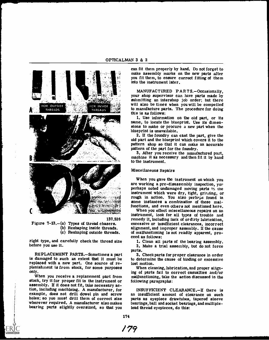
OPTICALMAN 3 & 2
Cs
2.1Vv:
4iti
137.526Figure 7-13.(a) Types of thread chasers.
(b) Reshaping inside threads.(c) Reshaping outside threads.
right type, and carefully check the thread sizebefore you use it.
REPLACEMENT PARTS.Sometimes a partis damaged to such an extent that it must bereplaced with a new part. One source of re-plenishment is from stock, for some purposesonly.
When you receive a replacement part fromstock, try it for proper fit in the instrument orassembly. If it does not fit, take necessary ac-tion, including machining. A manufacturer, forexample, does not drill dowel pin and screwholes; so you must drill them of correct sizewherever required. A manufacturer also makesbearing parts slightly oversized, so that you
t.
can fit them properly by hand. Do not forget tomake assembly marks on the new parts afteryou fit them, to ensure correct fitting of theminto the instrument later.
MANUFACTURED PART S.Occasionally,your shop supervisor can have parts made bysubmitting an intershop job order; but therewill also be times when you will be compelledto manufacture parts. The procedure for doingthis is as follows:
1. Use information on the old part, or itsname, to locate the blueprint. Use its dimen-sions to make or procure a new part when theblueprint is unavailable.
2. If the foundry can cast the part, give theold part and the blueprint which covers it to thepattern shop so that it can make an accuratepattern of the part for the foundry.
3. After you receive the manufactured part,machine it as necessary and then fit it by handto the instrument.
Miscellaneous Repairs
When you gave the instrument on which youare working a pre-disassembly inspection, yonperhaps noted undamaged moving parts in theinstrument which were dry, tight, grinding, orrough in action. You also perhaps found insome instances a combination of these mal-functions, and even others not mentioned here.
When you effect miscellaneous repairs on aninstrument, look for all types of trouble andremedy it, including lack of or dirty lubrication,excessive or insufficient clearances, incorrectalignment, and improper assembly. If the causeof malfunctioning is not readily apparent, pro-ceed as follows:
1. Clean all parts of the bearing assembly.2. Make a trial assembly, but do not force
parts.3. Check parts for proper clearance in order
to determine the cause of binding or excessivelost motion.
When cleaning, lubrication, and proper align-ing of parts fail to correct casualties and/ormalfunctioning, take the action discussed in thefollowing paragraphs:
INSUFFICIENT CLEARANCE.If there isan insufficient amount of clearance on suchparts as eyepiece drawtubes, tapered sleevebearings, ball and socket bearings, and multiple-lead thread eyepieces, do this:
174
/ 74
Chapter 7MAINTENANCE PROCEDURESPART I
1. Make a thin solution of pumice and clockoil (small amount of pumice at first) and put alittle portion of the solution on the parts as youreassemble the bearing.
2. Work the parts of the bearing back andforth, or rotate them until their movement is ofdesired freedom.
3. Disassemble the bearing and wash out alltraces of pumice and oil.
4. Reassemble the bearing, lubricate withthe proper type of lubricant, and check themotion.
Follow the procedure just described untilyou obtain the desired fit.
When there is insufficient clearance on aflat, sliding-surface bearing, do the following:
1. Put a thin coat of Prussian blue machin-ist's dye on a surface plate and rub the over-sized portion of the bearing assembly over thePrussian blue.
2. Carefully scrape away the high spots onthe bearing indicated by the Prussian blue.
CAUTION: Remove only a small amount ofmetal at a time, and make a trial assemblyafter you remove each amount. The importantthing here is prevention of the removal of toomuch metal from the bearing.
Another method for removing excess metalfrom a sliding-surface bearing" is to spread asmall portion of a thin mixture of pumice andclock oil over the surface of a flat lap and rubthe high part of the bearing over the surface ofthe coated flat lap. Use a sweeping figure-of-eight motion to ensure uniform removal of themetal. Do NOT remove too much metal.
EXCESSIVE CLEARANCE.If there is noway of adjusting a bearing by removing exces-sive clearance with shims, or the bearing doesnot have some means by which it can be ad-justed, replace it with a new one. If there issome way to adjust the bearing, however, adjustit as necessary in order to get a tight fit andthen remove high spots in the manner describedfor obtaining sufficient clearance.
NOTE: Always mark bearing parts to en-sure proper assembly after you hand fit themin the manner just described.
CLEANING AND PAINTING
Having completed all repairs to your instru-ment, you are now ready to accomplish essen-tial cleaning prior to painting. Reclean allparts on which you made repairs, to remove
175
traces of moisture, dirt, metal chips, andgrease from its surfaces. If a part does notrequire painting, put it in the container withother cleaned parts of the instrument.
Before you can successfully paint any metalobject, you'll have to get it thoroughly clean. Ifthe surface is covered with rust, or dirt, orgrease, the paint can't reach the metal. Itforms a loose coat that chips off or peels off.If you paint over grease or oil it will probablymix with your paint. And the mixture will dryvery slowly, or not at all.
Corrosion Removal
When a part is corroded, thoroughly clean itin order for the paint to adhere and give a goodfinish. This may be accomplished by using ap-proved commercial compounds. Always followthe manufacturer's instructions when you useany product, and protect yourself by followingsafety precautions.
Corrosion generally eats into a part, and thebest way to remove it is to soak the part for asufficient amount of time in a tank (stainlesssteel) of the compound.
If you do not have an approved corrosion re-moval compound, you may make some (for dif-ferent metals) by using the following formulas:
1. To make a corrosion removal compoundfor CAST IRON AND STEEL, use a 50 percentsolution of sulfuric acid and distilled water(about 150°F). Then dip the corroded metalparts in the warm acid for about 5 seconds andwash them immediately in several changes ofhot water.
CAUTION: Do not handle chemicals untilyou understand the safety precautions whichpertain to them. NEVER USE ACID ON BEAR-INGS, or GEAR TEETH.
2. You can make a corrosion removal com-pound for brass by using the following formula:
Water (pure, distilled 491 ccSulfuric acid (concentrated) . 435 ccNitric acid (concentrated) . 72 ccHydrochloric acid (concentrated). 2 cc
40
If a brass surface is bright in spots, thereis probably some clear lacquer on it. Sub-merge the part in paint remover and then rinseit with hot water. Continue by dipping the partin the correct amount of the corrosion removalsolution for 4 or 5 seconds, rinsing it in water,drying thoroughly with an air hose, and applying
OPTICALMAN 3 & 2
at least one coat of clear lacquer before thesurface oxidizes. NOTE: Do not use lacquerif the part requires paint.
CAUTION: Do not use a brass dip on bear-ing surfaces.
3. To clean corrosion from aluminum, dipit for 5 to 10 seconds in a 10 percent solutionof sodium hydroxide (lye) at a temperature ofabout 150°F and wash the lye off immediatelywith hot water.
You can also use some non-chemical meth-ods for removing corrosion and giving a bright,clean finish to metal parts. These methods in-volve types of abrasives, wire brushes, buffingwheels, and abrasive cloth, listed in the orderof discussion.
1. REMOVING CORROSION WITH A WIREBRUSH. There are two types of wire brusheswhich you may use to remove corrosion frommetal, rotary-power and hand.
CAUTION: To prevent damage to your eyes,wear your goggles to protect them from flyingwire. Do not use a wire brush on a bearingsurface or an engraved part.
To use a rotary-power wire brush, hold apart against the wheel with enough pressure toforce the moving wire bristles into the corro-sion and keep the part moving slowly and evenlyagainst the wheel. Run the wheel from the cen-ter of the part toward the edges, to ensurethoroughcleaning of the edges. Use a hand wirebrush, emery paper, or a scraper to removecorrosion from the inside corners of the part.
2. REMOVING CORROSION WITH A BUFF-ING WHEEL. A buffing wheel gives a part abrighter, polished finish than a wire brush(wheel), but it will not remove heavy corrosion.For this reason, do not use these wheels onlarge areas, but use them to polish metal partswhich must remain bright.
Use a polishing compound with a buffingwheel, and polish a part until you have the de-sired brightness and polish. Then remove theremains of the polishing compound with a sol-vent, dry the part thoroughly, and apply at leastone coat of clear lacquer.
NOTE: To speed up the buffing process,clean the parts first in a corrosion remover.
3. REMOVING CORROSION WITH ABRA-SIVE CLOTH. You can remove corrosion frommetal with an abrasive cloth in the followingmanner:
a. Polish flat pieces by hand on crocuscloth (embedded with an oxide of metal) laid ona flat surface.
176
b. Polish irregular pieces which youcannot buff on a wheel by hand. Use wood ormetal in the jaws of a vise to protect thesepieces and secure them ONLY as tightly asessential. To polish a piece in the vise, use astrip of fine emery cloth and complete the jobwith a piece of crocus cloth, to remove grainsproduced by the emergy cloth.
c. Put small, round parts of an instru-ment in the collet of a lathe and (with the latherunning at high speed) touch the parts lightlywith emery cloth or crocus cloth to the extentnecessary to obtain the polish desired.
CAUTION: Do not use abrasive cloth onbearing surfaces. When a bearing surface hasdeep pits caused by corrosion, it is worthless;the bearing is ruined. Use a non-abrasivecleaner to remove light corrosion from the sur-face of a bearing. Unless there are provisionsprovided in the construction of a bearing for re-fitting it, and you can do this in your shop, neverremove metal from a bearing surface. Whenyou remove corrosion from a bearing surface,rub it off carefully with crocus cloth or a finepaste of clock oil and pumice, or by scraping.
You have perhaps learned a great deal aboutsafety precautions in basic naval trainingcourses you studied previously; and they needlittle or no repetition here UNLESS THEY AREESPECIALLY APPLICABLE TO OPTICAL-MEN. The safety precautions listed and dis-cussed in the next section belong in the cate-gory of those important in a particular way toOpticalmen.
Study the following rules applicable when youwork with all kinds of chemicals. If you knowthem well, you may on occasions be able toprevent extensive harm and/or damage to yourbody as a result of their contact with it; youmay, in fact, even be able to save your life bythe knowledge you have about chemicals.
1. DIRECTIONS FOR USE.Study the di-rections on the container for using a specificchemical. If you mix chemicals improperly,or in incorrect proportions, they WIT:L NOTWORK and they MAY BE DANGEROUS. Suchmixtures sometimes explode and cause muchharm and damage.
CAUTION: NEVER MIX CHEMICALS ATRANDOM, OR PLAYFULLY, JUST TO FINDOUT WHAT HAPPENS. IF YOU DO THIS, YOUMAY NEVER LIVE LONG ENOUGH TO FINDTHE ANSWER TO YOUR CURIOSITY.
2. LABELS.Keep labels on containers andbottles of chemical intact. If you notice that a
Chapter 7MAINTENANCE PROCEDURESPART I
label is coming loose, glue it back in place.Then coat the label WITH PARAFFIN WAXTO PROTECT IT.
CAUTION: NEVER USE A CHEMICAL FROMAN UNLABELED CONTAINERGET RID OFIT IN THE PROPER MANNER.
3. WATER AND ACID.If you must mixwater and acid, POUR THE ACID VERYSLOWLY INTO THE WATER.
CAUTION: If you pour water into acid, theMIXTURE WILL BOIL OVER QUICKLY ANDBURN YOUR HANDS AND EVERYTHING ITTOUCHES.
4. ACID AND CYANIDE.The chemical re-action of acid and cyanide generates a deadlypoison.
5. CLEANLINESS.Keep chemicals and theircontainers clean, as well as all equipment, sup-plies, and spaces you use when handling chemi-cals. Even a small amount of dirt or grease,for example, may ruin your work.
6. CHEMICAL POISONING. Most chemicalsare poisonous, and many of them can burn yourclothes and hands. CAUTION: WEAR RUBBERGLOVES, A RUBBER APRON, AND GOGGLESWHEN YOU MIX CHEMICALS OR WORK WITHTHEM.
Learn by heart the antidotes for poisoningand burning by chemicals. This knowledge maysave your life.
Treat acid burns AS QUICKLY AS POSSI-BLE. Wash the acid off with an abundance ofwater and then wash your hands under a spigot,if they were involved. Continue by neutralizingall acid which remains with lime water, a mix-ture of equal parts of lime water and raw lin-seed oil, or a paste of baking soda and water.REMEMBER THIS: Baking soda is a base andit neutralizes acids. If acid gets in your eyes,wash it out with cold water and then WASHYOUR EYES WITH WEAK LIME WATER.
WASH ALKALI BURNS WITH PLENTY OFCOLD WATER; then neutralize remaining por-tions of the alkali WITH VINEGAR OR LEMONJUICE. REMEMBER THIS: Acids such asVINEGAR OR LEMON JUICE neutralize bases(alkalies) such as lye.
Some good antidotes for poisons are listednext. Study them carefully; better still, mem-orize as many as possible.
ACETIC ACID.Use an emetic to causevomiting. Magnesia, chalk, whiting in water,soap, oil, mustard, and salt are emetics. Aquick method for making a GOOD EMETIC is
177
to stir a TABLESPOONFUL OF SALT OR MUS-TARD into a glass of warm water.
HYDROCHLORIC, NITRIC, AND PHOS-PHORIC ACID.Use milk of magnesia, rawegg white, cracked ice, or a MIXTURE OFBAKING dODA AND WATER as an antidote forpoisoning by these acids.
CARBOLIC ACID.Some good antidotes forcarbolic acid are: egg white, lime water, oliveor castor oil with magnesia suspended in it,zinc sulfate in water, cracked ice, pure alcohol,or about 4 ounces of camphorated oil. Remem-ber particularly: Egg white, lime water, andcracked ice, for they will most likely be readilyavailable.
ALKALIES (sodium or potassium hydrox-ide).Good antidotes for poisoning by sodiumor potassium hydroxides are: vinegar, lemonjuice, orange juice, oil, or milk. You can easilyremember these antidotes.
ARSENIC (including rat poison and Parisgreen).Use milk, raw eggs, sweet oil, limewater, or flour and water as an ANTIDOTEFOR ARSENIC POISONING.
CYANIDE.Cyanide poisoning works so rap-idly that you can do little to prevent death,which this poison causes in less than a minute.If possible, GIVE HYDROGEN PEROXIDE TO AVICTIM. If breathing stops, apply artificialrespiration and let the patient breathe ammoniaor chlorine produced by chlorinated water. Ifthe victim is conscious, give him ferrous sul-fate in water; then give him emetics and keephim warm.
DENATURED ALCOHOL.Antidoes for poi-soning by denatured alcohol are: emetics, milk,egg white, and flour and water. If breathingstops, give artificial respiration.
IODINE.Give emetics, or plenty of starchor flour in water (stirred) as an antidote foriodine poisoning.
LEAD ACETATE (sugar of lead).Use emet-ics; sodium sulfate, potassium sulfate, or mag-nesium sulfate in water; milk; or egg whites asantidotes for lead acetate poisoning.
MERCURIC CHLORIDE (corrosive subli-mate).Some good antidotes for mercuric chlo-ride poisoning are: emetics, egg white, milk,table salt, castor oil, and zinc sulfate.
/41
OPTICALMAN 3 & 2
SILVER NITRATE. For poisoning by silvernitrate, give a solution of table salt and water.
The first thing to do for all types of gas poi-soning is this: GET THE VICTIM IN FRESHAIR IMMEDIATELY. IF HE STOPS BREATH-ING, GIVE HIM ARTIFICIAL RESPIRATION.
Breathe ammonia or amyl nitrite for poi-soning by carbon monoxide, illuminating gas,ethylene, or acetylene.
The antidote for poisoning by chloroformand ether is COLD WATER ON THE HEADAND CHEST.
Paint Removal
When you're going to repaint a surface that'salready painted, of course you'll have to re-move the old paint first. Apply a commercialpaint remover by brushing it onto the paintedsurface. (After you've used a brush for paintremover, don't use it again for any other pur-pose.)
Brush-on paint remover dissolves synthetic-bristle brushes, so use a natural-bristle brushand brush it on the painted surface of an in-strument part. Leave the paint remover on thepart as long as necessary for it to dissolve thepaint and then wipe it off. Finish the job byrinsing the part in lacquer thinner or benzeneto remove wax used in the remover as one ofthe ingredients.
Because it is difficult to wipe brush-on paintout of holes and corners, you will experiencesome difficulty in using it.
Paint and carbon removers are availablethrough Navy supply channels and also com-mercially. They are designated as SUPERcleaners. Besides removing paint, they removeheavy carbon, grease, varnish, and stickygums.
You will obtain the best results with a paintand carbon remover by putting at least 10 gal-lons in a stainless steel tank and soaking theparts as long as necessary in it. Then washeach part with hot water, remove the waterwith a compressed air hose, and bake it brieflyin an oven. It is then ready for painting.
Types of Paint
Some paint manufacturers make lacquersand enamels which put a fine finish on instru-ments. Many optical parts have a very smooth,hard finish which appears to be part of themetal itself. This finish is called ANODIZE,
178
applied to the metal by an electrochemicalprocess.
A baking enamel of high quality gives a hard,durable finish, but air-dried enamel is good fortouching up or painting an instrument whichcannot be subjected to heat in a baking oven.Lacquers have one outstanding characteristic,quick-drying, but they cannot resist chemicalsand are therefore not as durable as enamels.
Acrylic enamels sprayed from small aerosolcans are widely used in optical shops. Resultsare not as good as baking enamels or enamelssprayed from a gun, but such enamels are sat-isfactory for most instrument finishes.
CAUTION: Never cover enamel with lac-quer, because the lacquer loosens the enamelfrom its base and causes it to blister.
Lacquers and enamels which give a dull-flat, black finish are used to cut down surfacereflections, and they are also used to kill in-ternal reflections on the inside of optical in-struments. You will generally use a dull-blackfinish paint on most optical instruments.
Paints which give a semigloss, black ap-pearance and a hard, durable finish are used onparts which receive considerable handling, andon such small articles as eyepiece focusingrings, knobs, handles, and pointers.
Always use clear lacquer on parts subject tocorrosion but which are not painted, to protecttheir high polish.
Preparing Paint
Prepare both the primer coat and the finishcoat in the same manner for use in a spraygun, as follows:
1. Stir the paint thoroughly in order to mixthe pigment back into the liquid vehicles usedto suspend it. Unless you do this, the paint willnot cover surfaces with uniform thickness andwill not have luster and the same color allover.
2. Thin thick paint before you put it into aspray gun; otherwise, it will clog the gun andnot go through it. Follow the manufacturer'sinstructions when you thin the paint. Dip apencil vertically into the lacquer or enamel andthen withdraw it. If the consistency is correctfor spraying, the lacquer or enamel will run offthe pencil in a smooth, thin stream. When thin-ning paint, however, do not add much over 20percent of thinner to the paint, lest you get itso thin that it will not cover material properly.(Total volume of paint and thinner should be
Chapter 7MAINTENANCE PROCEDURESPART I
about 20% thinner.) After you add thinner, stirthe paint thoroughly.
3. When you have the paint at the right con-sistency for spraying, strain it through severalthicknesses of cheesecloth or medical gauze toeliminate lumps of undissolved pigment, dirt,and any other particles which could clog thespray gun and give a poor finish on your work.
Instrument Painting
After you remove corrosion from instru-ment parts, you are then ready to paint thosewhich require paint. There are three reasonsfor painting metal parts of optical instruments,as follows (in order of importance):
1. To protect the metal from rust and cor-rosion. This is most important for instru-ments used aboard ship, where salt spray anddamp, salty air quickly corrode unprotectedmetals.
2. To kill reflections. The glare of baremetal in the sunlight is very annoying to theuser of an optical instrument; and under someconditions, a brilliant reflection from a metalsurface may reveal the observer's presence toan enemy.
3. To improve appearance. A good-looking,pleasing appearance of an optical instrumentcreates a good impression on all who see anduse the instrument. Inspection of painted sur-faces of instruments is part of your mandatoryinspection procedure.
Most paints and their thinners are flamma-ble, and some are explosive; so use a spraybooth with an explosion-proof exhaust fan. Toprevent spontaneous combustion, put rags usedfor wiping up paints, oils, thinners, etc., in acontainer with a self-closing cover and disposeof them completely as soon as practicable.Stow paint materials in a locker which will nottip over, and at a temperature less than 95°F,preferablynever over 95°F.
CAUTION: Permit no smoking in the sprayroom, and have a CO2 fire extinguisher avail-able in the room's equipment. Do NOT playwith the air hose, or point it toward your ownperson or any one else.
When you paint with a spray gun (usually thecase), mask bearing surfaces, threads, andholes to the interior of the instrument, fromwhich you desire to exclude the paint. Tear offstrips of the tape and put them over the sur-faces of the bearings, with the edges of eachsuccessive strip (one side) slightly overlapping
the last strip applied. Then trim off excesstape with a sharp knife or razor blade. Maskoff also all points on the instrument you do notwish to paint.
Punch holes in a small box top or piece ofcardboard and stick the bodies of screws whoseheads you desire to paint into the holes, to keeppaint off the bodies of the screws. You canalso place on the cardboard top small partswhich you intend to paint on one side only.String parts which you desire to paint all overon small pieces of brass wire.
Before you use a spray gun for the firsttime, seek good information concerning its op-eration, or closely follow the manufacturer'sinstructions for its use. Check the spray gunfor cleanliness. If it is dirty or has old painton the inside, disassemble it completely andsoak the metal parts in a paint remover. Cleanthe gaskets in lacquer thinner. CAUTION:Paint remover will ruin the gaskets. When youreassemble the spray gun, lubricate all movingparts.
Fill the canister of the spray gun with yourprepared paint and turn on the air pressure,about 10 to 25 pounds per square inch, or asrecommended in the manufacturer's technicalmanual for the gun. Then so adjust the gun thatit delivers a fine spray with enough density tocover surfaces rapidly with a uniform, wet ap-pearance. Then begin your spraying.
Hold the spray gun about 10 inches fromyour work and keep it moving horizontally,back and forth. Be sure to carry each swing ofthe gun out past the end of the work before youstart back, to prevent piling up of the paint nearthe edges of the work and subsequent sagging.Start at the top of a surface and work down,back and forth in horizontal motion, and coverthe last old lap with about half of your new lap.If you follow this procedure, your paint will beuniformly thick over the entire surface.
After you finish a paint job with a spray gun,spray lacquer thinner over the gun to removelacquer and enamel from the small openings.At the end of the day, if you use the gun last,completely disassemble the gun and wash allparts in lacquer thinner. Then dry, lubricate,and reassemble it so that there will be no delayof work the next day. The best time to clean aspray gun is while the paint on its surfaces isstill wet.
NOTE: Your spray gun should have an airpressure and reducing valve with a water andoil trap (and filter)which should work correctly
179
1;
OPTICALMAN 3 & 2
all the time. Drain this trap regularly. Ifwater and oil get into your spray gun and paint,it will ruin the appearance of your work; andthe lacquer or enamel will not dry.
Finish Defects
Following is a list of difficulties sometimesexperienced with a spray gun, with the reasonfor each difficulty given.
FINISH REFUSES TO DRY. You forgot toremove the oil and grease from the metal sur-faces of your work, or from your air supply.
FINISH COVERED WITH TINY ROUGHSPOTS. There was too much dust or moisturein the air, or in the paint or spray gun.
FINISH HAS SMALL CIRCULAR MARK-INGS. There was water in the air hose, orwater dripped or condensed on the work beforeit was completely dry.
FINISH SHOWS HORIZONTAL STREAKS.Your spray was too fine and the last lap hadstarted to dry before you applied the next one,or you forgot to cover hall of each old lap withthe following lap.
FINISH IS UNIFORMLY ROUGH. Thespray was too fine, or you held the &I - too farfrom the work, and the droplets befo. to drybefore they hit the work.
THE FINISH HAS LUMPS OR BLOBS.The spray gun or hose line was dirty, or youforgot to strain the paint.
THE FINISH RUNS. The consistency ofthe paint was too thin.
THE FINISH SAGS. You moved the guntoo slowly or held it too close to the work.
THE FINISH SHOWS ORANGE-PEEL EF-FECT. The consistency of the paint was toothick, your spray was too fine, or you held thegun too far from the work.
Baking Procedure
When you intend to paint and bake instru-ment parts, remove all masking tape beforeyou put the parts in the oven. If you cannot re-move the tape before you bake the parts, re-move it immediately upon taking the parts outof the oven. This is also a good time to applyengraver filler, commonly called MONOFILL,a soft, wax-base compound (generally in crayonform) used to fill in and accentuate engravedindex lines and numbers. While the part is hot,the filler flows easily into an engraving. Whenthe part cools, wipe off the excess filler with a
180
18(
soft cloth. Always follow the paint manufac-turer's instructions on baking and drying thepaint that you use. When you do not have spe-cific instructions, a good rule of thumb to fol-low is bake for 2 1/2 hours at 250 degreesfahrenheit. For air dry enamel, allow 12 to 16hours at room temperature.
LEN CLEANING AND CEMENTING
Clean the lenses and prisms of an instru-ment you repair while paint on the finishedwork is drying, and also accomplish necessarylens cementing.
The Navy standard for cleaning glass opticalelements is this: OPTICS MUST BE CLEANEDTO ABSOLUTE PERFECTION.
Bear in mind that an optical instrument withcomponents of the highest quality arranged inthe best design possible is of little or no valueif vision through it is obscured by dirty optics.This statement does not mean grime or mud;IT MEANS THE SMALLEST VISIBLE SPECKOF DUST. EVEN A SPECK on a reticle mayobscure much detail of an image, and a finger-print or film of oil will most likely blur theoverall image.
For the reasons just given, you must learnthe proper technique for cleaning glass optics,and you must then APPLY THEM WITH PA-TIENCE, CARE, AND THOROUGHNESS. Knowl-edge of procedure, plus appreciation for qualitywork, will enable you to attain the absolute-perfection standard required.
CLEANING EQUIPMENT
The equipment you need for cleaning opticalelements includes a rubber or metal bulbsyringe, several camel's-hair brushes (small),alcohol, medically pure acetone, lens tissue(soft, tintless paper), absorbent cotton or silkfloss,wooden swab sticks, stoppered containersfor alcohol and acetone, and a container to keepthe cotton or silk floss absolutely clean. Tothis list you may also wish to add a speciallintless cloth for cleaning optics, the best typeof which is SELVYT CLOTH.
You can make a lens cleaning swab of cotton,silk floss, or lens tissue. To make a cotton orsilk floss swab, use the end of a wooden swabstick to pick up the top fibers of the material.Thrust the tip of the stick into the material androtate the stick until some fibers catch on it;then pull the captured fibers loose from the

Chapter 7MAINTENANCE PROCEDURESPART I
mother material. Repeat this process as oftenas necessary until you have the swab of desiredsize. Shape the swab by rotating its tip againsta clean cloth or lens tissue.
CAUTION: Do NOT touch the tip of the swabwith your fingers or lay it down on the benchtop where it will pick up dirt.
Figure 7-14 shows the procedure for makinga swab out of lens tissue, step by step. Swabsmade in this manner are useful for picking upindividual specks of dirt from a lens or reticle,using acetone as a cleaner. Make a supply oflens tissue strips for fabricating swags by cut-ting a packet of 4" x 6" lens tissue down thecenter, lengthwise, so that you can remove thestrips one at a time.
OARROW SHOWS DIRECTION TO FOLD
END
The fourth step for making a swab (4, fig.7-14) shows how to press the tip of the roundswab between the cover and the top tissue inorder to obtain a flat, chisel-like cleaning tip,as shown in step five (5) of illustration 7-14.
You can make a large, useful lens cleaningpad by folding two thickness of 8" x 11" lenscleaning tissue along its length and bringing thetwo ends together. When you dampen this padwith acetone, yoll can clean a large area ofglass quickly and effectively.
CLEANING PROCEDURE
The recommended procedure for cleaningglass optics is presented by steps in the fol-lowing paragraphs:
LENS TISSUE STRIP(FOLDED OVER STICK TIP)
OARROW SHOWS DIRECTION TO ROLL
PEGWOOD STICK
OFINISHING OFF
5 FINISHEDSWAB TIP
O
PEG-WOODSTICK
METHOD FOR OBTAINING A WIDECHISEL TIP ON END OF SWAB
Figure 7-14.Procedure for making a lens-tissue swab.
181'I'137.190
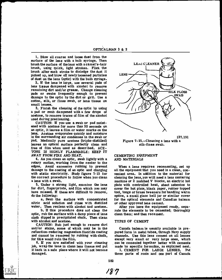
OPTICALMAN 3 & 2
1. Blow all coarse and loose dust from thesurface of the lens with a bulb syringe. Thenbrush the surface of the lens with a camel's-hairbrush, using quick, light strokes. Flick thebrush after each stroke to dislodge the dust itpicked up, and blow off newly loosened particlesof dust on the lens (optic) with the bulb syringe.
2. If the lens is large, use several pads oflens tissue dampened with alcohol to removeremaining dirt and/or grease. Change cleaningpads or swabs frequently enough to preventdamage to the optic by the dirt or grit. Use acotton, silk, or floss swab, or lens tissue onsmall lenses.
3. Finish the cleaning of the optic by usinga pad or swab dampened with a few drops ofacetone, to remove traces of film of the alcoholused during precleaning.
CAUTION: If you use a swab or pad moist-ened with acetone for more than 20 seconds onan optic, it leaves a film or water marks on thelens. Acetone evaporates quickly and moisturein the surrounding air condenses in the swab orpad. Medically pure acetone (triple-distilled)leaves an optical surface perfectly clean andfree of film when used as described. ACE-TONE IS HIGHLY FLAMMABLE; KEEP ITAWAY FROM FIRE AND HEAT.
4. As you clean an optic, swab lightly with arotary motion, working from the center to theedges. Avoid excessive rubbing to preventdamage to the coating of an optic and chargingwith static electricity. Study figure 7-15 forthe correct procedure to follow when you cleana lens with a swab.
5. Under a strong light, examine the lensfor dirt, fingerprints, and film which you mayhave missed. If these are difficult to remove,do the following:
a. Swab the surface with concentratednitric acid solution and rinse with distilledwater. Then reclean with alcohol and acetone.
b. If this procedure does not clean theoptic, rub the surface with a damp piece of lenscloth dipped in precipitated chalk. Then cleanwith alcohol and acetone.
CAUTION: Rub just enough to remove dirtand/or stains, some of which may be in thereflection-reducing magnesium fluoride coatingand cannot be removed by rubbing with chalk,for this would ruin the film.
6. If you are satisfied with your cleaningjob, wrap the lens in clean lens tissue and putit back in a safe place where it will not becomedamaged.
182
LEN3 CLEANER
LLENS r..."\
137.191Figure 7-15.Cleaning a lens with a
silk-floss swab.
CEMENTING EQUIPMENTAND MATERIALS
When a lens requires recementing, set upall the equipment that you need in a clean, con-venient area. In addition to the material forcleaning the lens,you will need a lens centeringmachine or 2 matched V blocks, an electric hotplate with controlled heat, sheet asbestos tocover the hot plate, black paper, rubber toppedtool, tongs or brass tweezers for handling warmoptics, a small glass bell jar or similar coverfor the optical elements and Canadian balsamor other approved lens cement.
After you have the equipment ready, sepa-rate the elements to be cemented; thoroughlyclean them; and then recement.
TYPES OF CEMENT
Canada balsam is usually available in pre-pared form in metal tubes, through Navy supplychannels. Use this lens cement on all lensesexcept very small or very large ones, whichcan be cemented together better with cementsmade by specific formulas, as explained next.
1. CEMENT FOR LARGE LENSES. Putthree parts of rosin and one part of Canada
/8 7
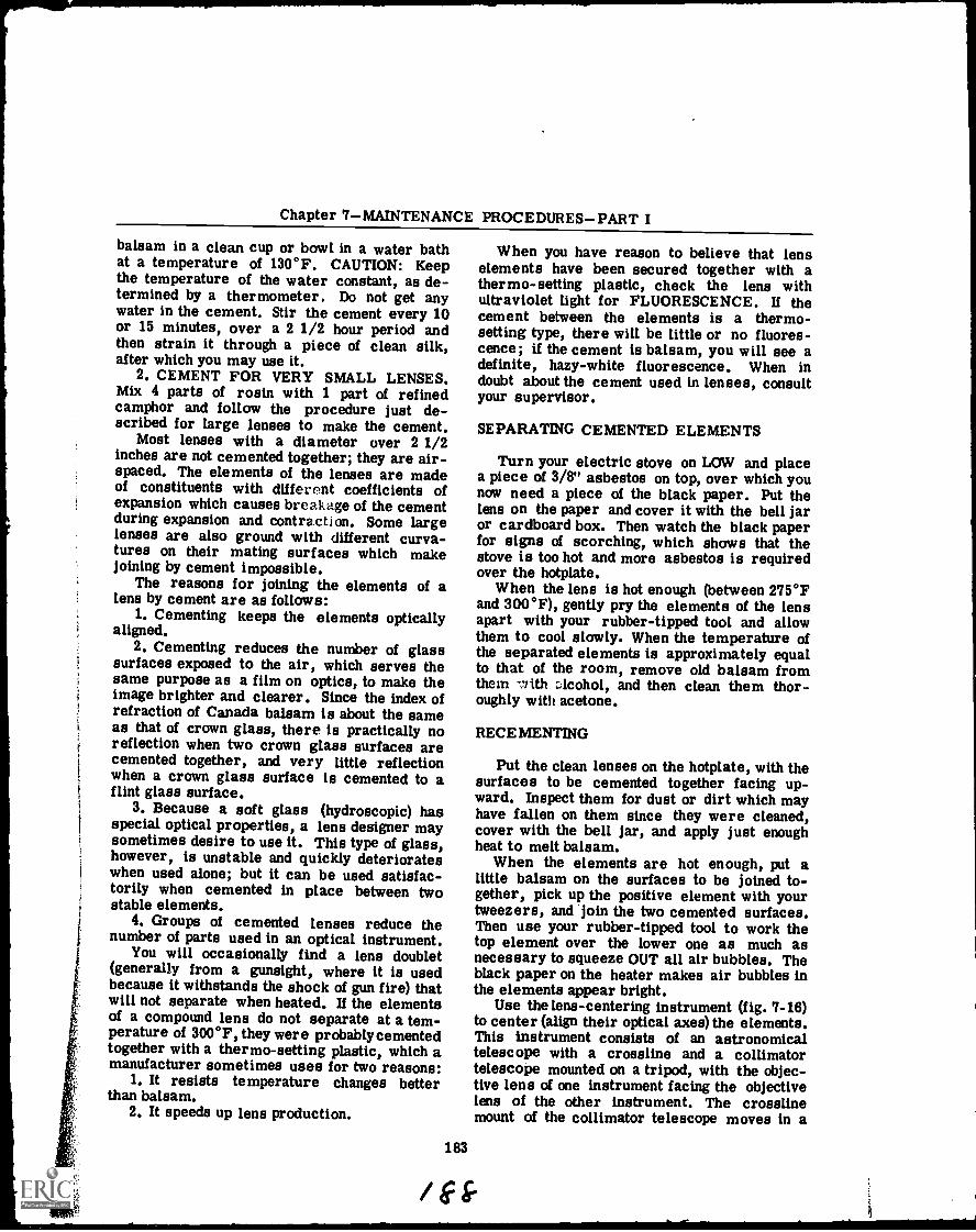
Chapter 7MAINTENANCE PROCEDURESPART I
balsam in a clean cup or bowl in a water bathat a temperature of 130°F. CAUTION: Keepthe temperature of the water constant, as de-termined by a thermometer. Do not get anywater in the cement. Stir the cement every 10or 15 minutes, over a 2 1/2 hour period andthen strain it through a piece of clean silk,after which you may use it.
2. CEMENT FOR VERY SMALL LENSES.Mix 4 parts of rosin with 1 part of refinedcamphor and follow the procedure just de-scribed for large lenses to make the cement.
Most lenses with a diameter over 2 1/2inches are not cemented together; they are air-spaced. The elements of the lenses are madeof constituents with different coefficients ofexpansion which causes breakage of the cementduring expansion and contraction. Some largelenses are also ground with different curva-tures on their mating surfaces which makejoining by cement impossible.
The reasons for joining the elements of alens by cement are as follows:
1. Cementing keeps the elements opticallyaligned.
2. Cementing reduces the number of glasssurfaces exposed to the air, which serves thesame purpose as a film on optics, to make theimage brighter and clearer. Since the index ofrefraction of Canada balsam is about the sameas that of crown glass, there is practically noreflection when two crown glass surfaces arecemented together, and very little reflectionwhen a crown glass surface is cemented to aflint glass surface.
3. Because a soft glass (hydroscopic) hasspecial optical properties, a lens designer maysometimes desire to use it. This type of glass,however, is unstable and quickly deteriorateswhen used alone; but it can be used satisfac-torily when cemented in place between twostable elements.
4. Groups of cemented lenses reduce thenumber of parts used in an optical instrument.
You will occasionally find a lens doublet(generally from a gunsight, where it is usedbecause it withstands the shock of gun fire) thatwill not separate when heated. If the elementsof a compound lens do not separate at a tem-perature of 300°F, they were probably cementedtogether with a thermo-setting plastic, which amanufacturer sometimes uses for two reasons:
1. It resists temperature changes betterthan balsam.
2. It speeds up lens production.
When you have reason to believe that lenselements have been secured together with athermo-setting plastic, check the lens withultraviolet light for FLUORESCENCE. If thecement between the elements is a thermo-setting type, there will be little or no fluores-cence; if the cement is balsam, you will see adefinite, hazy-white fluorescence. When indoubt about the cement used in lenses, consultyour supervisor.
183
SEPARATING CEMENTED ELEMENTS
Turn your electric stove on LOW and placea piece of 3/8" asbestos on top, over which younow need a piece of the black paper. Put thelens on the paper and cover it with the bell jaror cardboard box. Then watch the black paperfor signs of scorching, which shows that thestove is too hot and more asbestos is requiredover the hotplate.
When the lens is hot enough (between 275°Fand 300°F), gently pry the elements of the lensapart with your rubber-tipped tool and allowthem to cool slowly. When the temperature ofthe separated elements is approximately equalto that of the room, remove old balsam fromthem with alcohol, and then clean them thor-oughly with acetone.
RECE MENTING
Put the clean lenses on the hotplate, with thesurfaces to be cemented together facing up-ward. Inspect them for dust or dirt which mayhave fallen on them since they were cleaned,cover with the bell jar, and apply just enoughheat to melt balsam.
When the elements are hot enough, put alittle balsam on the surfaces to be joined to-gether, pick up the positive element with yourtweezers, and join the two cemented surfaces.Then use your rubber-tipped tool to work thetop element over the lower one as much asnecessary to squeeze OUT all air bubbles. Theblack paper on the heater makes air bubbles inthe elements appear bright.
Use the lens-centering instrument (fig. 7-16)to center (align their optical axes) the elements.This instrument consists of an astronomicaltelescope with a crossline and a collimatortelescope mounted on a tripod, with the objec-tive lens of one instrument facing the objectivelens of the other instrument. The crosslinemount of the collimator telescope moves in a
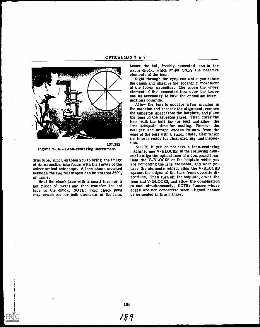
OPTICALMAN 3 & 2
137.192Figure 7-1U.Lens-centering instrument.
drawtube, which enables you to bring the imageof its crossline into focus with the image of theastronomical telescope. A lens chuck mountedbetween the two telescopes can be rotated 360°,or more.
Heat the chuck jaws with a small torch or ahot piece of metal and then transfer the hotlens to the chuck. NOTE: Cold chuck jawsmay crack one or both elements of the lens.
Mount the hot, freshly cemented lens in thewarm chuck, which grips ONLY the negativeelementb of the lens.
Sight through the eyepiece while you rotatethe chuck and observe the eccentric movementof the lower crossline. The move the upperelement of the cemented lens over the lowerone as necessary to have the crossline inter-sections coincide.
Allow the lens to cool for a few minutes inthe machine and recheck the alignment, removethe asbestos sheet from the hotplate, and placethe lens on the asbestos sheet. Then cover thelens with the bell jar (or box) and allow thelens adequate time for cooling. Remove thebell jar and scrape excess balsam from theedge of the lens with a razor blade, after whichthe lens is ready for final cleaning and inspec-tion.
NOTE: If you do not have a lens-centeringmachine, use V-BLOCKS in the following man-ner to align the optical axes of a compound lens:Heat the V-BLOCKS on the hotplate while youare cementing the lens elements; and when youhave the elements joined, slide the V-BLOCKSagainst the edges of the lens from opposite di-rections. Then turn off the hotplate, cover thelens and V-BLOCKS, and allow the combinationto cool simultaneously. NOTE: Lenses whoseedges are not concentric when aligned cannotbe cemented in this manner.
184
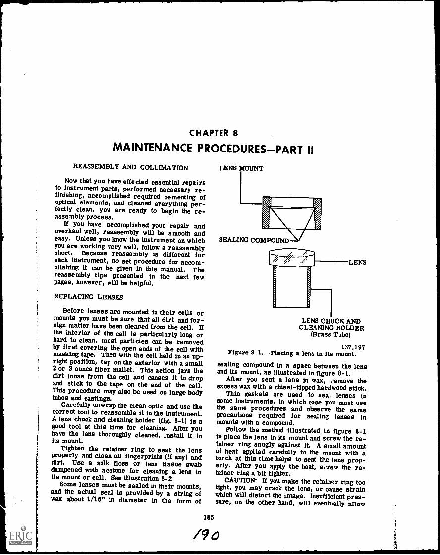
CHAPTER 8
MAINTENANCE PROCEDURES-PART II
REASSEMBLY AND COLLIMATION
Now that you have effected essential repairsto instrument parts, performed necessary re-finishing, accomplished required cementing ofoptical elements, and cleaned everything per-fectly clean, you are ready to begin the re-assembly process.
If you have accomplished your repair andoverhaul well, reassembly will be smooth andeasy. Unless you know the instrument on whichyou are working very well, follow a reassemblysheet. Because reassembly is different foreach instrument, no set procedure for accom-plishing it can be given in this manual. Thereassembly tips presented in the next fewpages, however, will be helpful.
REPLACING LENSES
Before lenses are mounted in their cells ormounts you must be sure that all dirt and for-eign matter have been cleaned from the cell. Ifthe interior of the cell is particularly long orhard to clean, most particles can be removedby first covering the open ends of the cell withmasking tape. Then with the cell held in an up-right position, tap on the exterior with a small2 or 3 ounce fiber mallet. This action jars thedirt loose from the cell and causes it to dropand stick to the tape on the end of the cell.This procedure may also be used on large bodytubes and castings.
Carefully unwrap the clean optic and use thecorrect tool to reassemble it in the instrument.A lens chuck and cleaning holder (fig. 8-1) is agood tool at this time for cleaning. After youhave the lens thoroughly cleaned, install it inits mount.
Tighten the retainer ring to seat the lensproperly and clean off fingerprints (if any) anddirt. Use a silk floss or lens tissue swabdampened with acetone for cleaning a lens inits mount or cell. See illustration 8-2
Some lenses must be sealed in their mounts,and the actual seal is provided by a string ofwax about 1/16" in diameter in the form of
LENS MOUNT
185
SEALING COMPOUND
LENS
LENS CHUCK ANDCLEANING HOLDER
(Brass Tube)
137.197Figure 8-1.Placing a lens in its mount.
sealing compound in a space between the lensand its mount, as illustrated in figure 8-1.
After you seat a lens in wax, ,.emove theexcess wax with a chisel-tipped hardwood stick.
Thin gaskets are used to seal lenses insome instruments, in which case you must usethe same procedures and observe the sameprecautions required for sealing lenses inmounts with a compound.
Follow the method illustrated in figure 8-1to place the lens in its mount and screw the re-tainer ring snugly against it. A small amountof heat applied carefully to the mount with atorch at this time helps to seat the lens prop-erly. After you apply the heat, screw the re-tainer ring a bit tighter.
CAUTION: If you make the retainer ring tootight, you may crack the lens, or cause strainwhich will distort the image. Insufficient pres-sure, on the other hand, will eventually allow
/90
OPTICALMAN 3 & 2
SILK FLOSS SWABS PUMP CAN FORCLEANING SOLUTION
[CLEANING SOLUTION
CLEANINGC LOTH7.
MOUNTED LENS
137.193Figure 8-2. Cleaning a lens in its mount.
the lens to become loose. It is therefore im-portant that you make certain a lens is actuallytight because the retainer ring is snug againstit and not because it appears tight only becausethe compound is holding it in position. If thisis true, when the compound dries, the lens willbe loose.
ASSEMBLING PRISMS
After you assemble all lenses in their cellsand mounts, assemble the prism clusters, orprism mounts (if any). Secure the prisms intheir mounts by straps and/or collars, whichmust fit snugly enough to hold the prisms butnot so tight that they may cause strain. Acollar should fit over a prism with a slightpress. If the fit is too tight, strain and break-age usually result; if the fit is too loose, theprism may shift its position and throw the in-strument out of adjustment.
When you assemble a prism cluster used asan erector assembly, check the assembly for
186
TELESCOPERETICLELINE
PRISMCLUSTER
)PRISMCLUSTERFIXTURE
PRISM SQUARINGFIXTURE
137.199Figure 8-3.--Prism squaring fixture.
LEAN before you put it into the instrument. Ina prism erecting system, LEAN results whenthe prisms are not oriented exactly 90° to eachother. Illustration 8-3 shows how to correctlean with a prism-squaring fixture. Note that
mmmEmessmomr
Chapter 8MAINTENANCE PROCEDURESPART II
the re:lairman is adjusting the prism by loosen-ing the collar and shifting it slightly. Hecan also detect LEAN and remove it by usingthe grids on a sheet of graft paper.
To remove lean from a prism cluster with aprism-squaring fixture, look at the grid throughthe prism cluster with one eye and at the sametime look directly at the grid with the othereye. If there is lean in the prism cluster, thegrids will not look parallel. This procedurefor detecting LEAN in the cluster is not aseasy as it sounds and takes practice in order toattain perfection.
If you assemble a pair of binoculars withLEAN in one or both barrels, the instrumentwill probably hurt the operators' eyes and willrequire disassembly and correction of theclusters for LEAN. So check for LEAN inprisms WITHOUT FAILURE before you assem-ble them in binoculars; and do not forget tocheck the prism clusters for strain after youassemble them and also prior to installation inthe instrument.
ASSEMBLING MECHANICAL PARTS
As you assemble parts in an instrument, besure to match all assembly marks; otherwise,you will be compelled to disassemble the in-strument, make corrections, and reassemble it.
Check each part as you reassemble it forfragments of foreign matter clinging to it.Each part MUST BE IMMACULATELY CLEANbefore you assemble it in the instrument. Keepopenings to the interior of the instrumentclosed with masking tape and remove it onlywhen you must make additional installations.Follow this procedure as you reassemble eachpart, until you make the final closure.
As you replace components and parts in aninstrument, try to work from the top down, toprevent unnecessary work over an optical ele-ment, and perhaps damage to it.
Do not force a part into place in an opticalinstrument; use a light press with the fingers;unless the part must be fitted in position byforce in ancordance with specifications. Ifthere is a bind, determine the cause.
You can make some adjustment on parts asyou assemble them in an instrument. Wheneverpossible, these adjustments should be madeduring collimation; but in some instances anadjustment is impossible after reassemblybecause of inaccessibility of parts. The re-moval of LEAN in an erector prism cluster is
187
a good example of an adjustment which must bemade during assembly.
Threads on retaining rings, lens mounts,caps, screws, and setscrews are extremely fineand can be cross threaded easily. When youtherefore insert them, turn in a counterclock-wise direction until the threads snap into place,and then turn clockwise. NOTE: Always placea small amount of grease or anti-seize com-pound on threads before you turn them intoplace.
Seal the final cover to the interior of anoptical instrument with sealing wax, gaskets,or packing. The function the instrument mustserve determines the method for sealing it, andthis is included in design specifications.
Seals used on optical instruments can beplaced in one of the following types:
1. Moisture seal.2. Gas-tight seal.3. Pressure seal
After you finis:1 the reassembly process, sealall openings except those you must use whenyou collimate the instrument. Upon completionof the collimation process, final sealing, dry-ing, and charging of the instrument must beaccomplished, as you will learn next.
COLLIMATION
One of the final steps in overhaul and repairof an optical instrument is collimation, whichis the ALIGNMENT OF THE OPTICAL AXISOF THE INSTRUMENT to its mechanical axis.In simpler terms, orientation of all the axes oflenses in an optical system in such manner thatthey coincide with each other in a straight lineand parallel to the mechanical axes of thebearing surfaces (telescope's mounting pads,for example) of the instrument is known ascollimation.
Suppose you have an instrument construchdonly of a straight tubular housing mounted intwo ball bearings like a shaft. It contains nooptics: it is only a straight, hollow tube. Ifyou now peer through this tube and rotate it onits bearings like a rotating shaft, you will findthat the least amount of rotation is in the cen-ter of the tube. THIS CENTER OF LEASTROTATION IS THE MECHANICAL AXIS OFTHE TUBE.
If you point the tube toward an infinity tar-get, you can superimpose this mechanical axison the object. Regardless of the direction inwhich you rotate the tube, its mechanical axis
/94
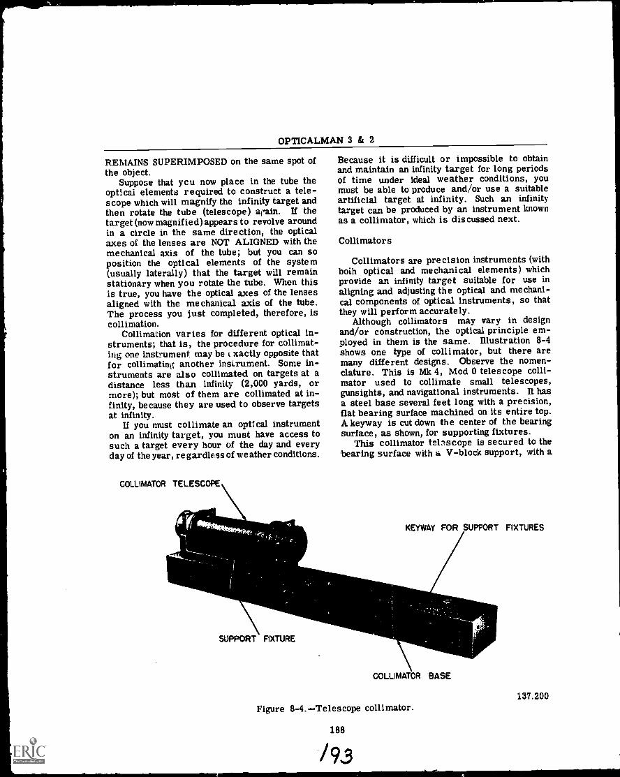
OPTICALMAN 3 & 2
REMAINS SUPERIMPOSED on the same spot ofthe object.
Suppose that ycu now place in the tube theoptical elements required to construct a tele-scope which will magnify the infinity target andthen rotate the tube (telescope) again. If thetar get (now magnified) appears to revolve aroundin a circle in the same direction, the opticalaxes of the lenses are NOT ALIGNED with themechanical axis of the tube; but you can soposition the optical elements of the system(usually laterally) that the target will remainstationary when you rotate the tube. When thisis true, you have the optical axes of the lensesaligned with the mechanical axis of the tube.The process you just completed, therefore, iscollimation.
Collimation varies for different optical in-struments; that is, the procedure for collimat-ing one instrument may be xactly opposite thatfor collimating another instrument. Some in-struments are also collimated on targets at adistance less than infinity (2,000 yards, ormore); but most of them are collimated at in-finity, because they are used to observe targetsat infinity.
If you must collimate an optical instrumenton an infinity target, you must have access tosuch a target every hour of the day and everyday of the year, regardless of weather conditions.
COLLIMATOR TELESCOPE
illi
SUPPORT FIXTURE
Because it is difficult or impossible to obtainand maintain an infinity target for long periodsof time under ideal weather conditions, youmust be able to produce and/or use a suitableartificial target at infinity. Such an infinitytarget can be produced by an instrument knownas a collimator, which is discussed next.
Collimators
Collimators are precision instruments (withboth optical and mechanical elements) whichprovide an infinity target suitable for use inaligning and adjusting the optical and mechani-cal components of optical instruments, so thatthey will perform accurately.
Although collimators may vary in designand/or construction, the optical principle em-ployed in them is the same. Illustration 8-4shows one type of collimator, but there aremany different designs. Observe the nomen-clature. This is Mk 4, Mod 0 telescope colli-mator used to collimate small telescopes,gunsights, and navigational instruments. It hasa steel base several feet long with a precision,flat bearing surface machined on its entire top.A keyway is cut down the center of the bearingsurface, as shown, for supporting fixtures.
This collimator telescope is secured to thebearing surface with a V-block support, with a
KEYWAY FOR SUPPORT FIXTURES
.7__
COLLIMATOR BASE
137.200Figure 8-4.Telescope collimator.
188
X93
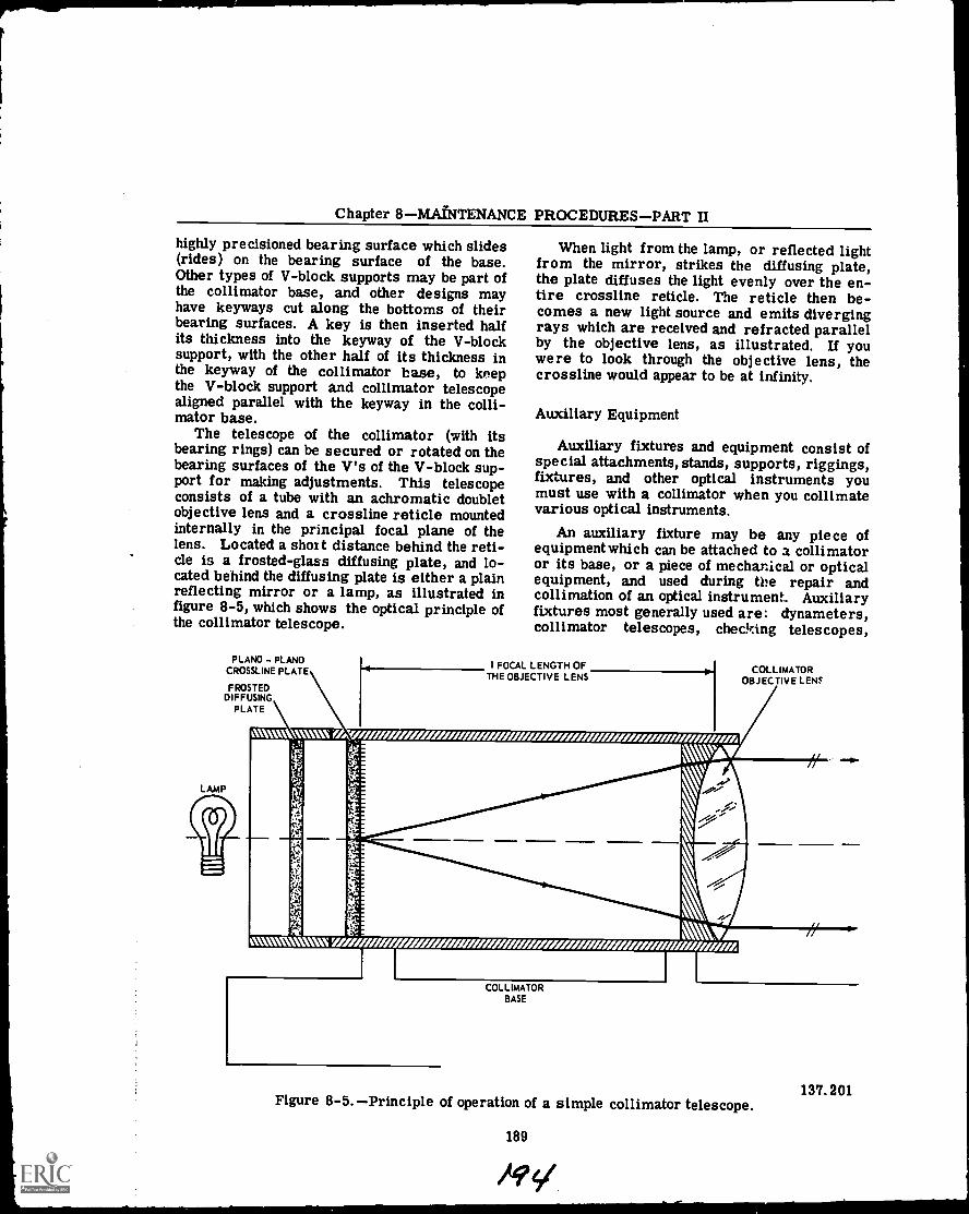
Chapter 8MAINTENANCE PROCEDURESPART II
highly precisioned bearing surface which slides(rides) on the bearing surface of the base.Other types of V-block supports may be part ofthe collimator base, and other designs mayhave keyways cut along the bottoms of theirbearing surfaces. A key is then inserted halfits thickness into the keyway of the V-blocksupport, with the other half of its thickness inthe keyway of the collimator base, to keepthe V-block support and collimator telescopealigned parallel with the keyway in the colli-mator base.
The telescope of the collimator (with itsbearing rings) can be secured or rotated on thebearing surfaces of the V's of the V-block sup-port for making adjustments. This telescopeconsists of a tube with an achromatic doubletobjective lens and a crossline reticle mountedinternally in the principal focal plane of thelens. Located a shoat distance behind the reti-cle is a frosted-glass diffusing plate, and lo-cated behind the diffusing plate is either a plainreflecting mirror or a lamp, as illustrated infigure 8-5, which shows the optical principle ofthe collimator telescope.
PLANO - PLANOCROSSLINE PLATE
FROSTEDDIFFUSING
PLATE
LAMP
When light from the lamp, or reflected lightfrom the mirror, strikes the diffusing plate,the plate diffuses the light evenly over the en-tire crossline reticle. The reticle then be-comes a new light source and emits divergingrays which are received and refracted parallelby the objective lens, as illustrated. If youwere to look through the objective lens, thecrossline would appear to be at infinity.
Auxiliary Equipment
Auxiliary fixtures and equipment consist ofspecial attachments, stands, supports, riggings,fixtures, and other optical instruments youmust use with a collimator when you collimatevarious optical instruments.
An auxiliary fixture may be any piece ofequipment which can be attached to a collimatoror its base, or a piece of mechanical or opticalequipment, and used during the repair andcollimation of an optical instrument. Auxiliaryfixtures most generally used are: dynameters,collimator telescopes, checking telescopes,
1 FOCAL LENGTH OFTHE OBJECTIVE LENS
COLLIMATOROBJECTIVE LENS
NWN% 'WVWM,7
VA;
\ VIPA
COLLIMATORBASE
Figure 8-5.Principle of operation of a simple collimator telescope.
189
137.201
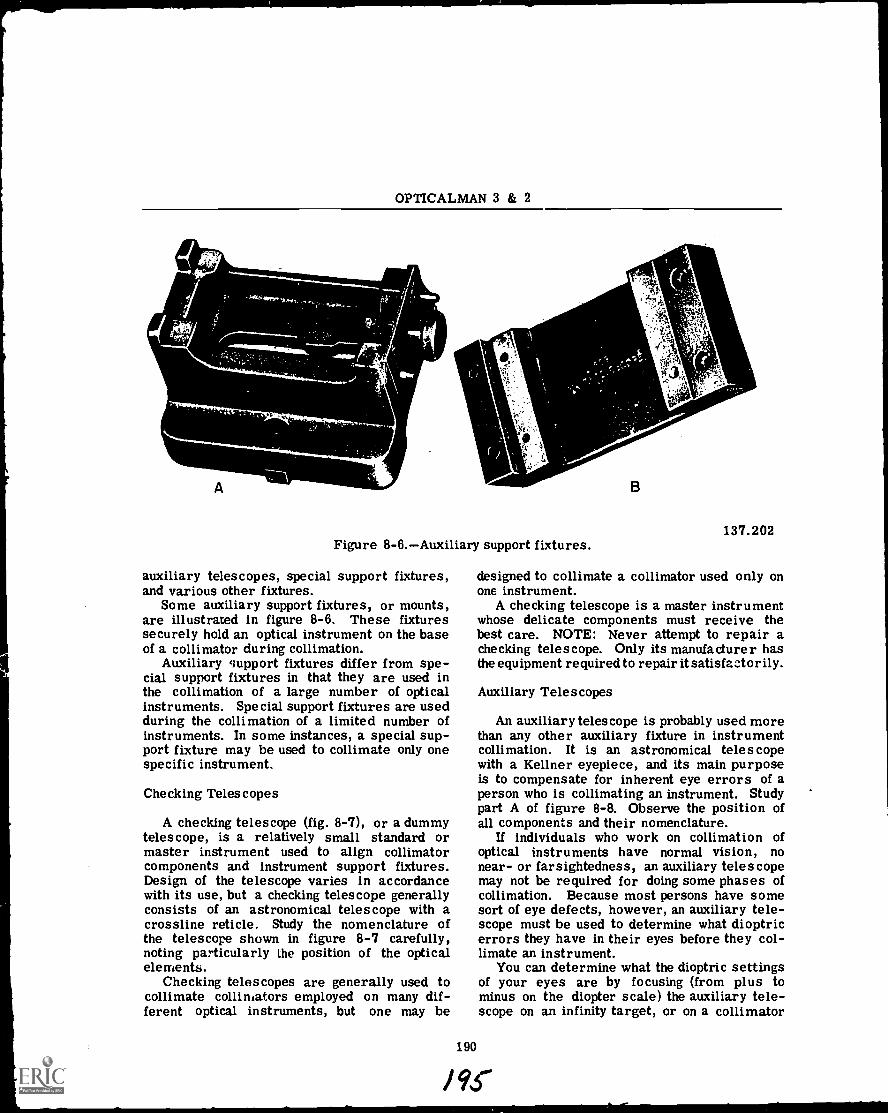
OPTICALMAN 3 & 2
t.;
A
\
Figure 8-6.Auxiliary support fixtures.
auxiliary telescopes, special support fixtures,and various other fixtures.
Some auxiliary support fixtures, or mounts,are illustrated in figure 8-6. These fixturessecurely hold an optical instrument on the baseof a collimator during collimation.
Auxiliary support fixtures differ from spe-cial support fixtures in that they are used inthe collimation of a large number of opticalinstruments. Special support fixtures are usedduring the collimation of a limited number ofinstruments. In some instances, a special sup-port fixture may be used to collimate only onespecific instrument.
Checking Telescopes
A checking telescope (fig. 8-7), or a dummytelescope, is a relatively small standard ormaster instrument used to align collimatorcomponents and instrument support fixtures.Design of the telescope varies in accordancewith its use, but a checking telescope generallyconsists of an astronomical telescope with acrossline reticle. Study the nomenclature ofthe telescope shown in figure 8-7 carefully,noting particularly the position of the opticalelements.
Checking telescopes are generally used tocollimate collimators employed on many dif-ferent optical instruments, but one may be
190
yts
oolk
.4
137.202
designed to collimate a collimator used only onone instrument.
A checking telescope is a master instrumentwhose delicate components must receive thebest care. NOTE: Never attempt to repair achecking telescope. Only its manufacturer hasthe equipment required to repair it satisfactorily.
Auxiliary Telescopes
An auxiliary telescope is probably used morethan any other auxiliary fixture in instrumentcollimation. It is an astronomical telescopewith a Kellner eyepiece, and its main purposeis to compensate for inherent eye errors of aperson who is collimating an instrument. Studypart A of figure 8-8. Observe the position ofall components and their nomenclature.
If individuals who work on collimation ofoptical instruments have normal vision, nonear- or farsightedness, an auxiliary telescopemay not be required for doing some phases ofcollimation. Because most persons have somesort of eye defects, however, an auxiliary tele-scope must be used to determine what dioptricerrors they have in their eyes before they col-limate an instrument.
You can determine what the dioptric settingsof your eyes are by focusing (from plus tominus on the diopter scale) the auxiliary tele-scope on an infinity target, or on a collimator
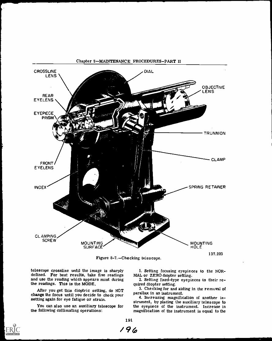
Chapter 8MAINTENANCE PROCEDURESPART II
CROSSLINELENS
REAREYELENS
EYEPIECEPRISM
FRONT/EYELENS
INDEX
CLAMPINGSCREW
MOUNTINGSURFACE
DIAL
s"thisliitv..\,11.A.1
OBJECTIVELENS
TRUNNION
CLAMP
SPRING RETAINER
Figure 8-7.Checking telescope.
telescope crossline until the image is sharplydefined, For best results, take five readingsand use the reading which appears most duringthe readings. This is the MODE.
After you get this dioptric setting, do NOTchange the focus until you decide to check yoursetting again for eye fatigue or strain.
You can also use an auxiliary telescope forthe following collimating operations:
191
MOUNTINGHOLE
137.203
1. Setting focusing eyepieces to the NOR-MAL or ZERO diopter setting.
2. Setting fixed-type eyepieces to their re-quired diopter setting.
3. Checking for and aiding in the removal ofparallax in an instrument.
4. Increasing magnification of another in-strument, by placing the auxiliary telescope tothe eyepiece of the instrument. Increase inmagnification of the instrument is equal to the
/ 9 6
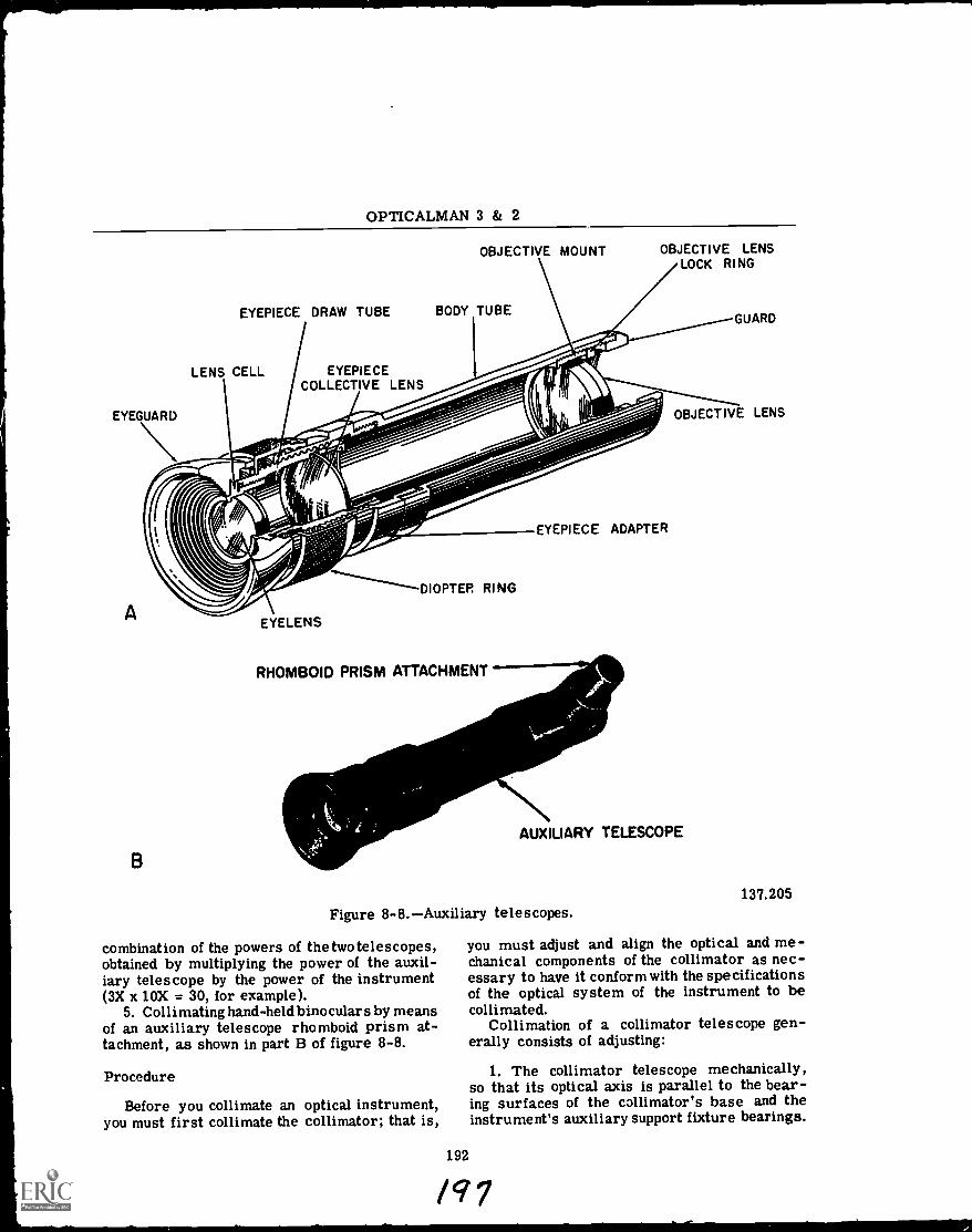
OPTICALMAN 3 & 2
EYEGUARD
A
B
EYEPIECE DRAW TUBE
OBJECTIVE MOUNT
BODY TUBE
OBJECTIVE LENSLOCK RING
GUARD
LENS CELL EYEPIECECOLLECTIVE LENS
EYELENS
DIOPTER RING
RHOMBOID PRISM ATTACHMENT
EYEPIECE ADAPTER
OBJECTIVE LENS
AUXILIARY TELESCOPE
Figure 8-8.Auxiliary telescopes.
combination of the powers of the two telescopes,obtained by multiplying the power of the auxil-iary telescope by the power of the instrument(3X x 10X = 30, for example).
5. Collimating hand-held binoculars by meansof an auxiliary telescope rhomboid prism at-tachment, as shown in part B of figure 8-8.
Procedure
Before you collimate an optical instrument,you must first collimate the collimator; that is,
192
137.205
you must adjust and align the optical and me-chanical components of the collimator as nec-essary to have it conform with the specificationsof the optical system of the instrument to becollimated.
Collimation of a collimator telescope gen-erally consists of adjusting:
1. The collimator telescope mechanically,so that its optical axis is parallel to the bear-ing surfaces of the collimator's base and theinstrument's auxiliary support fixture bearings.
lci 7
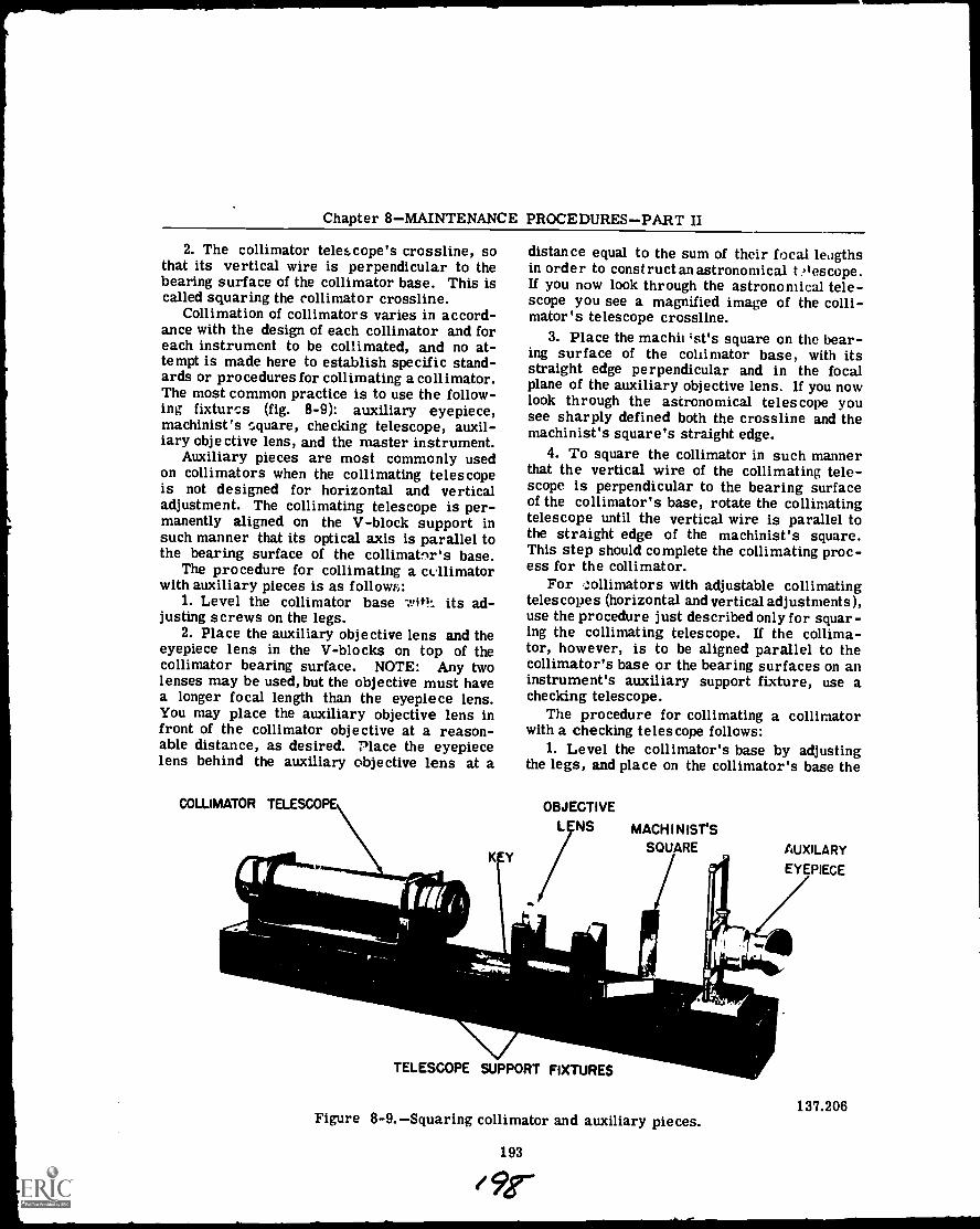
Chapter 8MAINTENANCE PROCEDURESPART II
2. The collimator telescope's crossline, sothat its vertical wire is perpendicular to thebearing surface of the collimator base. This iscalled squaring the collimator crossline.
Collimation of collimators varies in accord-ance with the design of each collimator and foreach instrument to be collimated, and no at-tempt is made here to establish specific stand-ards or procedures for collimating a collimator.The most common practice is to use the follow-ing fixtures (fig. 8-9): auxiliary eyepiece,machinist's square, checking telescope, auxil-iary objective lens, and the master instrument.
Auxiliary pieces are most commonly usedon collimators when the collimating telescopeis not designed for horizontal and verticaladjustment. The collimating telescope is per-manently aligned on the V-block support insuch manner that its optical axis is parallel tothe bearing surface of the collimator's base.
The procedure for collimating a collimatorwith auxiliary pieces is as follow:::
1. Level the collimator base wit!: its ad-justing screws on the legs.
2. Place the auxiliary objective lens and theeyepiece lens in the V-blocks on top of thecollimator bearing surface. NOTE: Any twolenses may be used, but the objective must havea longer focal length than the eyepiece lens.You may place the auxiliary objective lens infront of the collimator objective at a reason-able distance, as desired. Place the eyepiecelens behind the auxiliary objective lens at a
COLLIMATOR TELESCOPE
K Y
distance equal to the sum of their focal leagthsin order to construct an astronomical t ,lescope.If you now look through the astronomical tele-scope you see a magnified image of the colli-mator's telescope crossline.
3. Place the machit,st's square on the bear-ing surface of the collimator base, with itsstraight edge perpendicular and in the focalplane of the auxiliary objective lens. If you nowlook through the astronomical telescope yousee sharply defined both the crossline and themachinist's square's straight edge.
4. To square the collimator in such mannerthat the vertical wire of the collimating tele-scope is perpendicular to the bearing surfaceof the collimator's base, rotate the collimatingtelescope until the vertical wire is parallel tothe straight edge of the machinist's square.This step should complete the collimating proc-ess for the collimator.
For collimators with adjustable collimatingtelescopes (horizontal and vertical adjustments),use the procedure just described only for squar-ing the collimating telescope. If the collima-tor, however, is to be aligned parallel to thecollimator's base or the bearing surfaces on aninstrument's auxiliary support fixture, use achecking telescope.
The procedure for collimating a collimatorwith a checking telescope follows:
1. Level the collimator's base by adjustingthe legs, and place on the collimator's base the
OBJECTIVE
LENS
TELESCOPE SUPPORT FIXTURES
MACHINIST'SSQUARE AUXILARY
EYEPIECE
Figure 8-9.Squaring collimator and auxiliary pieces.
193
9r.
137.206
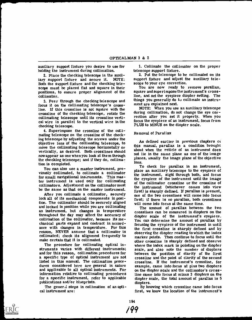
OPTICALMAN 3 & 2
auxiliary support fixture you desire to use forholding the instrument during collimation.
2. Place the checking telescope in the auxil-iary support fixture and secure it. NOTE:Both the support fixture and the checking tele-scope must be placed flat and square in theirpositions, to ensure proper alignment of thecollimator.
3. Peer through the checking telescope andfocus it on the collimating telescope's cross-line. If this crossline is not square with thecrossline of the checking telescope, rotate thecollimating telescope until its crossline verti-cal wire is parallel to the vertical wire in thechecking telescope.
4. Superimpose the crossline of the colli-mating telescope on the crossline of the check-ing telescope by adjusting the screws under theobjective lens of the collimating telescope, tomove the collimating telescope horizontally orvertically, as desired. Both crosslines shouldnow appear as one when you look at them throughthe checking telescope; and if they do, collima-tion is completed.
You can also use a master instrument, pre-viously collimated, to collimate a collimatorfor small navigational instruments. This mas-ter instrument is used only for collimatingcollimators. Adjustment on the collimator mustbe the same as that on the master instrument.
After you collimate a collimator, securelylock all of its mechanical components in posi-tion. The collimator should be securely alignedand locked in position while you are collimatingan instrument, but changes in temperaturethroughout the day may affect the accuracy ofcollimation of the collimator, because its me-chanical parts expand and contract in accord-ance with changes in temperature. For thisreason, NEVER assume that a collimator iscollimated; check its alignment frequently tomake certain that it is collimated.
The procedure for collimating optical in-struments varies with different instruments;and for this reason, collimation procedures fora specific type of optical instrument are notlisted in this manual. The collimation proce-dures considered here are general in natureand applicable to all optical instruments. Forinformation relative to collimating proceduresfor a specific instrument, refer to applicablepublications and/or blueprints.
The general steps in collimation of an opti-cal instrument are:
1. Collimate the collimator on the propertelescope support fixture.
2. Put the telescope to be collimated on itssupport fixture and adjust the auxiliary tele-scope to your eye correction.
You are now ready to remove parallax,square and superimpose the instrument's cross -line, and set the eyepiece diopter setting. Thethings you generally do to collimate an instru-ment are explained next.
NOTE: When you use an auxiliary telescopeduring collimation, de not change the eye cor-rection after you set it properly. When youfocus the eyepiece of an instrument, focus fromPLUS to MINUS on the diopter scale.
Removal of Parallax
As defined earlier in previous chapters ofthis manual, parallax is a condition broughtabout when the reticle of an instrument doesnot lie in the same plane as one of the imageplanes, usually the image plane of the objectivelens.
To check for parallax in an instrument,place an auxiliary telescope to the eyepiece ofthe instrument, sight through both, and focusthe eyepiece of the instrument until the imageof the collimator crossline or the crossline ofthe instrument (whichever comes into viewfirst) is sharply defined. If parallax is present,one of the two crosslines will come into focusfirst; if there is no parallax, both crosslineswill come into focus at the same time.
The amount of parallax between the twocrosslines can be measured in diopters on thediopter scale of the instrument's eyepiece.You can determine the amount of parallax byfocusing the eyepiece of the instrument in untilthe first crossline is sharply defined and byobserving the diopter reading to which the indexmarker points. Then continue to focus until theother crossline is sharply defined and observewhere the index mark is pointing on the diopterscale, and also note the number of dioptersbetween the position of clarity of the firstcrossline and the point of clarity of the secondcrossline. If the instrument's crossline, forexample, came into focus at plus two diopterson the diopter scale and the collimator's cross-line came into focus at minus 3 diopters on thediopter scale, the total amount of parallax is 5diopters.
By knowing which crossline came into focusfirst, we know the location of the instrument's
194
/99
Chapter 8MAINTENANCE PROCEDURESPART II
crossline in relation to the focal plane (imageplane) of the objective lens. If the instrument'scrossline comes into focus first before thecollimator's crossline, the instrument's cross-line is farther from the objective lens than itsfocal plane (image plane). If the collimator'scrossline comes into focus before the instru-ment's crossline, the instrument's crossline iscloser to the objective lens than its focal plane.
The problem in collimation now is to placethe instrument's crossline in the focal plane ofthe objective lens, in one of two ways:
1. Move the instrument's crossline forwardor aft axially until it is in the focal plane of theobjective lens.
2. Move the objective lens until its focalplane is in the same plane as the instrument'scrossline. This method is preferred for plac-ing the crossline of an instrument in the focalplane of its objective lens. The objective lensis mounted in an externally threaded mountwhich can be moved axially along the interiorof the instrument. When the objective lensmount is moved any amount, the focal plane andimage of the collimator's crossline in the focalplane move in the same direction and the sameamount as the objective lens.
In some instruments, spacers or separatorsare placed in front and at the rear of the ob-jective lens mount (not threaded externally) toallow for axial positioning of the mounts in or-der to remove parallax.
Removal of parallax by axial adjustment ofthe instrument's crossline is nut preferredover axial adjustment of the objective lens,because a portion of the telescope's body mustusually be disassembled in order to reach thecrossline. Instruments which provide for ad-justment of the crossline have it mounted in anexternally threaded mount which can be ad-justed by screwing forward or backward. Someoptical instruments also provide for adjustingboth the objective lens and the crossline.
After you completely remove parallax froman instrument, both crosslines must come intofocus at the same time on the same diopterreading on the diopter scale of the instrument.
NOTE: There is NO tolerance for parallaxin any optical instrument.
Squaring and Superimposingthe Cross line
You can square and superimpose the cross-line in the following manner:
1. Square the crosslines of the instruments;that is, have the vertical line of one parallelwith the vertical line of the other. You can dothis by rotating the crossline of the instrumentin its mount with a cotton swab or a soft,rubber-tipped eraserNOT THE FINGERS.You must do this carefully in order to preventscratches on the glass surface of the crossline,for these defects appear greatly magnified whensuperimposed on the target.
2. When you have the crossline positionedcorrectly, tighten its retainer ring. If you findthat the crossline rotates with the retainer ringwhen you tighten it, so position the crosslinethat it will rotate into correct position (squared)when you tighten its retainer ring.
3. Superimpose the instrument's crosslinewith the crossline of the collimator, so thatboth crosslines appear as one when you look atthem through the instrument. You can do thisin several ways, but the method generally usedis to rotate the objective lens' eccentric mountand ring (if provided). When you rotate themount and ring, or each singly, the optical axisof the objective lens moves laterally and causesthe image of the collimator's crossline to movein the same direction and in a circle. So ma-nipulate the eccentric mount and ring that yousuperimpose the collimator's crossline imageon the crossline of the instrument.
In some objective lenses, the optical centersare slightly different from the geometricalcenters, which means that you can rctate theobjective lens in its mount and give the sameeffect you get by using an eccentric mount andring.
Another method for superimposing the cross-line is to adjust the crossline and its mountlaterally with a screw adjustment mount (de-scribed in chapter 6). Adjust the screws asnecessary to push the crossline of the instru-ment horizontally and vertically and superim-pose it over the image of the collimator'scrossline.
You can superimpose the crossline of in-struments containing a prism erecting systemby adjusting the erecting prism. An excellentexample of this is an Amici prism in a gunsighttelescope. The prism is positioned at a definitepoint between the objective lens and its focalplane; and movement of the prism causes theoptical axis and focal plane to move in thedesired direction until the image of the colli-mator's crossline is superimposed with thecrossline of the instrument.
195
0 o
OPTICALMAN 3 & 2
The diopter setting of eyepieces varies inaccordance with type, focusing or fixed-type,each of which is set to different optical values.
A focusing-type eyepiece is set to a valuecalled 0 DIOPTERS, which can be accomplishedwhen an infinity target (collimator crossline)image is defined sharply, with parallel rays oflight emerging from the rear eyelens, and withthe index mark pointing to 0 diopters on thediopter scale of the instrument's eyepiece.NOTE: Parallel rays of light have 0 dioptricvalue.
You will recall that when you removed par-allax from an instrument the images of thecrosslines of the instrument and the collimatorcame into focus with the same reading on thediopter scale, regardless of the reading (plusor minus). If one image, for example, comesinto focus at -4 diopters on the diopter scale,the other image must do likewise. This meansthat the eyepiece focusing mechanism must befocused in from its mid-throw (mechanical 0diopters) position to allow the images to coin-cide with the principal focal plane of the eye-piece. (When images or objects are in theprincipal focal plane of any lens, the rays whichleave the images diverge, enter the lens, arerefracted, and emerge parallel.) The problem,then, is to move the images OUT toward theobserver to the mid-throw position, so that youdo not need to focus the draw tube of the eye-piece IN past its mid-throw position.
A condition exactly opposite to that justdescribed may also exist; that is, if both im-ages come into focus on the plus side of 0 di-opters, your problem is to move the images INto the mid-throw position so that you need notmove the draw tube OUT in order to have theprincipal focal plane coincide with the images.
The procedure for moving these images to-gether simultaneously depends upon the type oferecting system in the instrument; that is, asingle erector or a two erector (lens) system.The rule to follow for moving a single erectorlens is as follows: If the images come intofocus on the MINUS side of the 0 diopter gradu-ation on the diopter scale, move the erectorlens AWAY from the eyepiece; if the imagescome into focus on the PLUS side of the 0 di-opter graduation, move the erector lens TO-WARD the eyepiece. Review the discussion onconstruction of telescopes in chapter 7 of thismanual.
It may appear that the opposite effect occursto the movement of the image when you move
the erector lens; but if you remember the opti-cal theory involved here, you know that theimages move in the opposite direction to themovement of the single erector lens. Move theerector lens in the desired direction until theimages are in focus, with the index mark point-ing to 0 diopters on the eyepiece diopter scale.NOTE: You need an auxiliary telescope forsetting the 0 diopter on any telescope eyepiece.
Give the diopter setting a final check byplacing the auxiliary telescope to the eyepieceof the instrument and then by focusing from aPLUS to a MINUS position until you have theimages sharply defined. The index mark mustpoint to 0 diopters on the diopter scale withint quarter of a diopter tolerance.
To set a two-erector lens erecting systemto 0 diopters, move the second lens in thesystem in the direction in which the imagesmust be moved. The theory involved here isthis: The light rays which enter the seconderector lens are parallel and the images formedby the lens are in the focal plane of the seconderector lens. The images in the focal planetherefore always move in the same direction asthe lens. When you have the second erectorlens properly positioned, when focused on theimages, the eyepiece comes into focus with theindex mark pointing to 0 diopters on the diopterscale.
The required diopter setting for a fixed-typeeyepiece must be explained only for collimationof a fixed-prism gunsight (Mk 77 and Mk 79,for example), be cause the mechanical construc-tion of this telescope must be known before youset the diopter setting.
SEALING, DRYING,AND CHARGING
After you collimate an optical instrument,the last step in the repair process involvessealing, drying, and charging, which is dis-cussed next.
Methods used for sealing, drying, and charg-ing differ for the various types, designated forthis purpose as: (1) moisture-tight, (2) gas-tight, and (3) pressure-tight.
Optical instruments which are held by hand,or not permanently mounted on a ship's weatherdecks, must be moisture-tight. These instru-ments always have focusing-type eyepieces andare sealed:
1. Against the entrance of moisture, andhumidity.
196
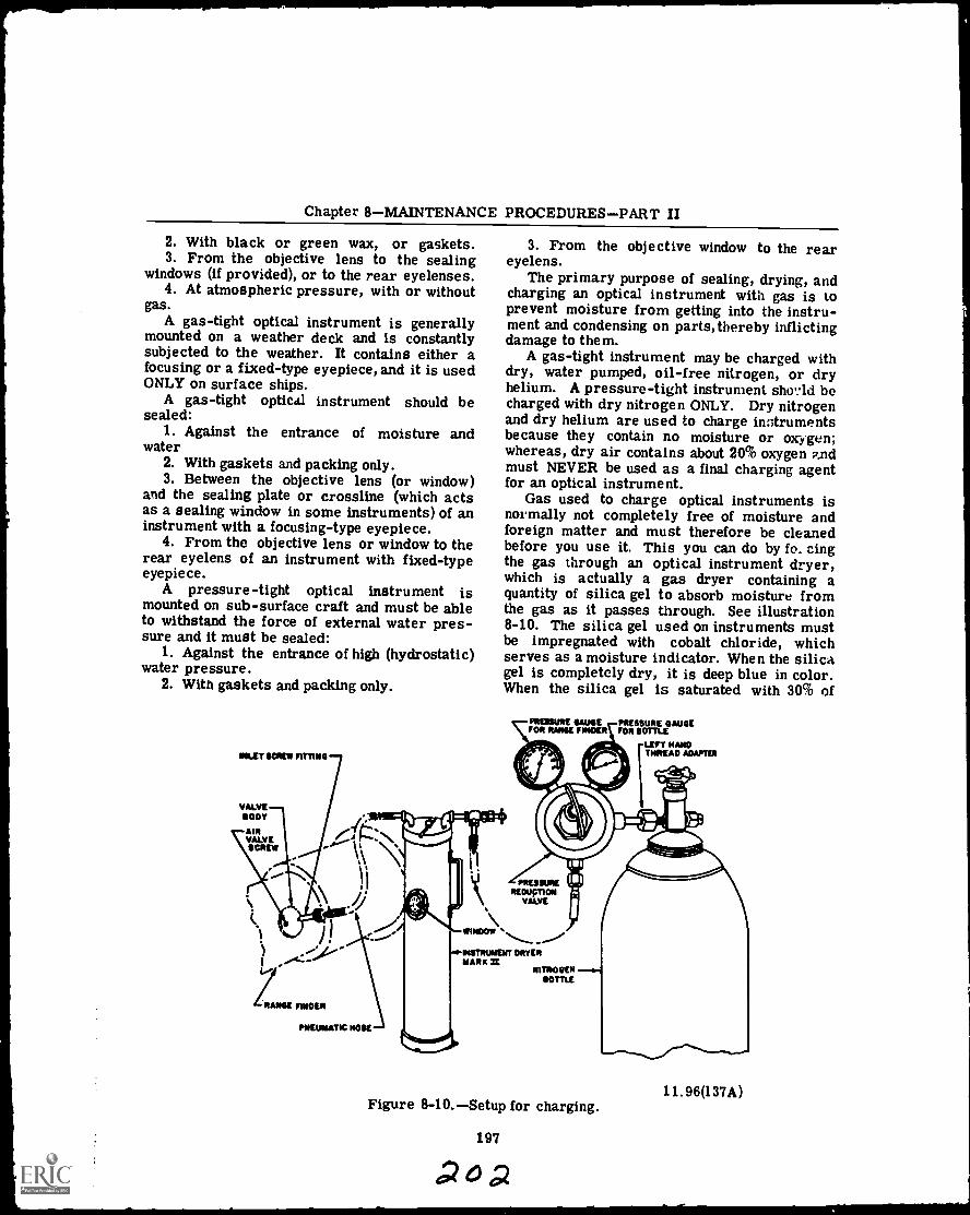
Chapter 8MAINTENANCE PROCEDURESPART II
2. With black or green wax, or gaskets.3. From the objective lens to the sealing
windows (if provided), or to the rear eyelenses.4. At atmospheric pressure, with or without
gas.A gas-tight optical instrument is generally
mounted on a weather deck and is constantlysubjected to the weather. It contains either afocusing or a fixed-type eyepiece, and it is usedONLY on surface ships.
A gas-tight optical instrument should besealed:
1. Against the entrance of moisture andwater
2. With gaskets and packing only.3. Between the objective lens (or window)
and the sealing plate or crossline (which actsas a sealing window in some instruments) of aninstrument with a focusing-type eyepiece.
4. From the objective lens or window to therear eyelens of an instrument with fixed-typeeyepiece.
A pressure-tight optical instrument ismounted on sub-surface craft and must be ableto withstand the force of external water pres-sure and it must be sealed:
1. Against the entrance of high (hydrostatic)water pressure.
2. With gaskets and packing only.
INLET scan FITTING
VALVEBODY
MRVALVESCREW
3. From the objective window to the reareyelens.
The primary purpose of sealing, drying, andcharging an optical instrument with gas is toprevent moisture from getting into the instru-ment and condensing on parts, thereby inflictingdamage to them.
A gas-tight instrument may be charged withdry, water pumped, oil-free nitrogen, or dryhelium. A pressure-tight instrument sho,..ld becharged with dry nitrogen ONLY. Dry nitrogenand dry helium are used to charge instrumentsbecause they contain no moisture or oxygen;whereas, dry air contains about 20% oxygen P.ndmust NEVER be used as a final charging agentfor an optical instrument.
Gas used to charge optical instruments isnormally not completely free of moisture andforeign matter and must therefore be cleanedbefore you use it. This you can do by fo_ cingthe gas through an optical instrument dryer,which is actually a gas dryer containing aquantity of silica gel to absorb moisture fromthe gas as it passes through. See illustration8-10. The silica gel used on instruments mustbe impregnated with cobalt chloride, whichserves as a moisture indicator. When the silicagel is completely dry, it is deep blue in color.When the silica gel is saturated with 30% of
PREMIUM GAUGE PRESSURE GAMFOR NAME FINDER FOR BOTTLE
LEFT HANDTHREAD ADAPTER
21
ROHM FINDER
PNEUMATIC NOSE
VHIMOVI _."'1141111UNENT DRYERMARE IE
NITROGENBOTTLE
11.96(137A)Figure 8-10.Setup for charging.
197
Boa
OPTICALMA.N 3 & 2
water, its color is lavender; and when it con-tains 50% of moisture, its color is pale pinkAt a saturation of almost 100% with moisture,silica gel is decidedly pink in color.
A window on the side of the cylinder enablesyou to observe the color of the silica gel; andwhen it changes to pink, remove it from thecylinder, place ;t in a container, and bake it inan oven at a temperature of 300°F to 350°F fora minimum of 4 hours, after which its colorshould be a deep blue.
All optical instruments except moisture-tighttypes are equipped with gas inlet and outletvalves, also called plugs; and on most instru-ments they are located on opposite ends of theinstruments. As the gas enters through the in-let valve and circulates throughout the instru-ment, it becomes saturated with moisture in theinstrument and carries it out through the outletvalve.
After you overhaul a gas-tight instrument,check its gaskets, fittings, and so forth, for airtightness.
When pressure testing an instrument followthe requirements of the technical manual thatapplies to the instrument. The manual will giveyou the type of gas to be used and at what pres-sure. Most navigational instruments and peri-scopes use dry nitrogen as a gas, so the follow-ing discussion on safe handling and pressuretesting will be applied to the use of nitrogen.The same safety rules and charging procedureswill apply to any compressed gas.
The use of nitrogen gas for pressure-testingnavigational instruments, as prescribed in thevarious instrument manuals, requires that theuser be familiar with safe-handling practice ofpressure gases and the storage cylinders. It isalso advisable that the tester have generallyapplicable information on the question of clean-liness which is useful for these tests.
The nitrogen will be supplied to you in thestandaru type of gas cylinder. Fortunately,nitrogen is an inert gas, chemically speaking,which eliminates the fire and explosion hazardsassociated with other gases such as oxygen,acetylene, etc. But the nitrogen is under greatpressure in the storage cylinder and damage tothe cylinder can result in its bursting. Also,the economic loss of damaged cylinder it. to beavoided. The following rules for storage, han-dling and use of cylinders shall be strictlyobserved.
Avoid abusing cylinders. They are care-fully checked at the charging plait for safe
198
condition. Ahuse may easily render themunsafe.
BE SURE THE CYLINDER CONTAINSNITROGEN and do not tamper with the identify-ing code numbers and markings on the cylinders.
Store cylinders in an approved safe place.A. Store cylinders in a definitely assigned
place where they will not be knockedover of damaged by passing or fallingobjects. If a full cylinder falls over,it may crack and explode. If the cyl-inder valve is broken, the cylinder willtake off, like a jet-propelled rocket.
B. Cylinders should be kept away fromstoves, radiators, furnaces and otherhot places.
While moving cylinders, keep them frombecoming knocked over or from falling. Asuitable hand cart should be available. Thecart should have retaining devices such aschains and fitting recesses to hold the cylinders.
Keep cylinders from being knocked ovowhile in use; a rack should be provided.
Full cylinders should be used in the orderreceived from the charging plant.
Never allow cylinders to come in contactwith live wires and ground wires of electricalequipment.
Always close cylinder valve when work isfinished and always close valves of empty cyl-inders while in storage before returning tocharging plant.
Return empty cylinders promptly.The pressure tests in the instrument manu-
als specify a source of clean, dry nitrogen atpressures of two to five pounds per square inch.The equipment setup for such a source of nitro-gen is illustrated in Fig. 8-10
The pressure-reducing regulator gives anoutput of nitrogen at a constant pressure as de-termined by the setting of its pressure- adjustingcontrol screw. Two gauges, which are part ofthe regulator, indicate the high cylinder pres-sure and the regulated output pressure.
The instrument dryer contains a replaceabledirt filter and a replaceable cartridge of desic-cant to filter out foreignparticles and moisture.A viewing window is provided to permit a con-stant check of the desiccant for the tell-talechange from blue to pink which indicates thatthe desiccant is saturated and needs replace-ment. This is to be done at the first sign ofpinkness in the desiccant. The dirt filter shouldbe checked when tha desiccator is replaced.Use a new filter at the first sign of dirt.

Chapter 8MAINTENANCE PROCEDURESPART II
Desiccators and fi'ters are much cheaper thanthe spoilage of one ewly overhauled instrument.
Plastic hose must be used from the pressuregas filter. Rubber hoses are not clean. Theytend to "shed" foreign matter. It is also ad-visable to use a plastic hose from the regulatorto the filter, but rubber will do if plastic is notavailable.
The following procedure shall be followed. Itis prescribed to protect you and the equipment.
Set a cylinder of nitrogen in a rack. Ob-serve the rules for "Safe-handling Practice forCylinders." Make sure the cylinder containsnitrogen.
With the cylinder firmly in the rack, un-screw the valve protection cap from the top ofthe cylinder.
"Crack" the cylinder valve by opening itone-quarter of a turn and then closing it im-mediately. DO NOT stand in front of the outletpipe; stay in back of it. This "cracking" is in-tended to clear the valve and outlet pipe of dustand dirt that may have been accumulated duringstorage and shipment. Otherwise, such dirtmight be blown into the regulator and damageit.
CAUTION
Do not use a wrench on the cylindervalve. It should open to hand pres-sure. If it will not yield by hand,replace the valve protection capand return the cylinder to thecharging plant with an explanationattached.
Assemble the pressure-reducing regula-tor to the outlet of the cylinder. Tighten theunion-joint nut securely.
Turn the pressure-adjusting control screwof the regulator counterclockwise (to the left)until it is loose. This protects the regulatorand its gauges from possible damage when thecylinder is opened.
Stand away to one side of the front of theregulator and open the cylinder valve slightly.If the cylinder was opened wide, the suddenrush of gas might damage the regulator. Onlyopen the valve enough to make the cylinderpressure gauge indicate a slow rise in pres-sure. When the needle of the gauge stops, openthe cylinder valve all the way.
CAUTION
If there is a leak between the cyl-inder and the regulator, close thecylinder valve before tightening thecoupling or doing anything else.
Connect the hoses and the pressure gasfilter together as in figure 8-10.
Turn the pressure-adjusting control screwof the regulator clockwise until the regulatedpressure gauge reads five pounds. This willblow out the filter and the lines.
Reduce the pressure again. The system isnow ready for use.
When an instrument is to be tested for leaksthe general procedure is:
Connect the hose from the outlet valve ofthe dryer to the inlet valve screw fitting (thesmall screw by the male-threaded end) on theoptical instrument (A of fig. 8-11).
199
AO V
A
B
0.--f Mt 1.1 ,
137.207Figure 8-11.Optical instrument dryer.
OPTICALMAN 3 & 2
Open the gas inlet screw (large screw) onthe inlet valve.
Tighten the gas outlet valve screw on theopposite end of the optical instrument.
Turn on the air supply until the pressuregage on the instrument dryer reads approxi-mately five (5) pounds per square inch (B, fig.8-11).
While you maintain this pressure, use aliquid soap solution to test for leaks around allfittings, gaskets, screws, the objective window,and the rear eyelens.
If you find leaks, mark them with a softlead pencil, white crayon, or chalk, turn off theair supply, disconnect the hose from the instru-ment, and then repair the leak(s).
After you repair leaks, connect the hoseto the instrument and apply the same pressuretest and check again for leaks with soapsuds.
After the instrument passes the soapsudstest, maintain the 5 pounds of pressure andclose the gas valve screw on the inlet valve.
If the instrument you are working on has afixed-type or an internal-focusing eyepiece,continue with the following tank test. (NOTE:You can also submerge an instrument with anexternal-focusing eyepiece, but ONLY up to theeyepiece.)
Submerge the instrument in a tank ofwater.
Check for slow rising bubbles which mayappear anywhere on the instrument. A fewhours may elapse before any bubbles are visible.
Mark the leak(s) as soon as you removethe instrument from the tank, and then repairthem. Follow up by submerging the instrumentin the tank again and make a double check forleaks.
When you are certain there are no leaks inthe instrument, remove it from the tank anddry its exterior with a clean, soft cloth. Thenrecharge it to exactly 5 pounds. Twenty-fourhours later, attach a pressure gage to the gasinlet valve of the instrument and check itspressure. If it has dropped, repeat either thesoapsuds test or the tank test as often as nec-essary until you find the leak(s). Then makenecessary repairs and dry the instrument.
You now have the instrument ready forcharging with nitrogen, which you can do in thefollowing manner:
Reconnect the outlet hose from the dryerto the inlet valve on the instrument.
Open the outlet valve of the instrument.
Turn on the nitrogen gas and let it cyclethrough the entire instrument.
Purge the instru:nent by holding a fingerover its outlet valve. When the gage on thedryer shows a pressure up to but not exceedingfive pounds, remove your finger from the outletvalve and allow the gas to escape from the in-strument. At about five minute intervals duringa period of approximately one-half hour, repeatthe purging operation.
When you have the instrument purged(completely free of moisture), replace the out-let valve screw and let the pressure on thedryer build up to approximately two pounds, oras indicated in the overhaul manual for theinstrument.
When the pressure reaches the specificamount, close and secure the gas valve screw(large one)on the gas inlet valve and disconnectthe hose from the optical instrument. Thenturn off the nitrogen bottle and replace thesmall, inlet valve screw.
Some moisture-tight instruments have inletand outlet screws (not valves) which can beused for drying the instrument only. When youseal a moisture-tight instrument, test it forleaks and dry it; then replace the inlet and out-let screws.
Pressure-tight instruments must withstanda special testing procedure, so check with yourinstructor or shop supervisor for the instruc-tions and specifications applicable to a particu-lar pressure-tight instrument.
A special procedure must be followed fordisassembling the equipment, as well. Thefollowing procedure is intended to protect youand the equipment.
Close the cylinder valve. The pressurereadings on both gauges should drop to zero ifthe hose line is open.
Turn the pressure-adjusting control screwcounterclockwise until it is loose.
Disconnect the hoses and the pressure gasfilter from the regulator.
Disconnect the cylinder from the regulatorby unscrewing the union-joint nut on the coupling.
If a regulator is to be out of service forseveral weeks or longer, screw in the pressure-adjusting control screw to just relieve thespring pressure on the valve seat. At thispoint the control screw will no longer be loose.This aids in lengthening the life of the valveseat. Before the regulator is used again, thecontrol screw must be loosened as prescribedin the setting up procedure.
200
opir
Chapter 8MAINTENANCE PROCEDURESPART II
In all cases of handling press,;re gas, followthe rules outlined herein and exercise cautionalways.
Charge all gas- and pressure-tight instru-ments with gases and pressures specified forthem, at the times stated next:
1. Prior to the conclusion of each ship'soverhaul.
2. When inspection indicates condensationon internal optical surfaces.
3. Immediately after completion of an over-haul of an optical instrument.
4. At the completion of twelve months ofservice.
Some general rules to follow when you re-charge an optical instrument are:
1. NEVER recharge an optical instrumentwhen the temperature is below 32°F.
2. NEVER charge an instrument with nitro-gen, or helium after the pressure in the bottleor tank falls below 400 pounds per square inch.
NOTE: If there is a trace of moisture, oilor grease in the bottle, it starts to come outwhen the pressure falls below 400 pounds.
3. Recharge each instrument with only thetype of gas and pressure specified for that par-ticular instrument. If in doubt, use nitrogen,and pressurize the instrument to two (2)pounds.
4. When the inlet valve or the area near itis painted ORANGE or YELLOW, always chargethe instrument with HELIUM. CAUTION:NEVER use nitrogen. Follow recommendedand/or Navy approved instructions for chargingan instrument with helium.
HEAT TREATING AND TEMPERING
The Opticalman will work with metals atvarious times while working on optical instru-ments. Thus he should be familiar with typesof metals, the properties of metals, and theheat treating processes for the most commonmetals.
There is no simple definition of metal. Allchemical elements that possess metallic prop-erties are classed as metals. The metallicproperties might be defined as luster, goodthermal and electrical conductivity, and thecapability of being permanently shaped, or tosome extent deformed, at room temperature.Other chemical elements, lacking these prop-erties, are classed as nonmetals. Someelementscarbon, phosphorus, silicon, andsulfur, for examplebehave sometimes likemetals, sometimef like nonmetals, and are
201
40
known as metalloids. An alloy is defined as asubstance having metallic properties, that iscomposed of two or more elements.
Metals and alloys vary widely in their char-acteristics or properties. Chemical propertiesinvolve the behavior of the metal in contact withthe atmosphere, salt water, or (Alio. environ-ments. Physical properties relate to color,density and weight, magnetic qualities, electri-cal conductivity or resistance, and teat con-ductivity. Mechanical properties relate to loadcarrying ability, wear resistance, and elasticity.
The various properties of metals and alloyshave been determined in the laboratories ofmanufacturers and are tabulated and indexed byvarious engineering societies interested inmetallurgical development. Charts which giveproperties pertaining to a particular metal oralloy are published in such reference books asthe Metals Handbook. The charts provideinformation on the physical and mechanicalproperties which have been determined.
What are the properties which an Opticalmanneeds to understand about the metals mostcommonly used? They include the mechanicalproperties of hardness, toughness, tensilestrength, ductility, and malleability. Followingis an explanation of the meaning of these terms.
The HARDNESS of a metal is that propertywhich enables it to resist scratching, denting,cutting, or erosion. It may also be defined asthe ability of the metal to resist penetration.A piece of lead, for example, can easily bescratched with a knife. But it would be difficultto mark a piece of steel in this manner. Thereason is that steel possesses the property ofhardness, and thus provides resistance toscratching and cutting.
TOUGHNESS is that property of a metalwhich enables it to withstand shock loadingwithout breaking.
It is thus related to strength and to ductility.Usually, the hardness of a metal increases asthe toughness decreases.
TENSILE STRENGTH is that property of ametal which resists forces that would tend topull the metal apart. It is measured in termsof pounds per square inch which represents theload that must be exerted on a cross-sectionalarea in order to break the metal.
DUCTILITY is that property that renders ametal capable of being drawn into wire form,stamped, cr hammered into sheets. In otherwords, when the metal is placed under a severeload, it deforms rather than fractures.
OPTICALMAN 3 & 2
MALLEABILITY is the property of metalthat permits it to be rolled, forged, hammered,or drawn, without cracking or breaking.
CORROSION RESISTANCE though not a me-chanical property is also of primary impor-tance. Corrosion resistance is the propertythat enables a metal to withstand chemical orelectrochemical attack by air, moisture, soil,or other agents.
The various mechanical properties describedmay at times be desirable, and at other timesbe undesirable, depending on the purpose forwhich the metal is to be used. But resistanceto corrosion is always a highly desirablecharacteristic.
TYPES OF METALS
The metals with which you work can bedivided into two general classifications, ferrousand nonferrous. FERROUS metals are thosethat are composed primarily of iron. NON-FERROUS metals are those that are composedprimarily of some element or elements otherthan iron. Nonferrous metals or alloys some-times contain a small amount of iron as analloying element or as an impurity.
Ferrous Metals
A few examples of ferrous metals includepig iron, cast iron, ingot iron, and wroughtiron. Carbon steel and the various alloy sf eelsstructural as well as tool steelare also con-sidered as ferrous metals since they arecomposed of iron to which relatively smallpercentages of carbon and other elements havebeen added as alloys.
Pig iron is composed of about 93 percentiron, from 3 to 5 percent carbon, and varyingamounts of other elements. It is comparativelyweak and brittle, and has a limited use.
The term cast iron may be applied to anyiron in which the carbon alloy is more than 1.7percent. Cast iron has high compressivestrength and good wear resistance, but it lacksductility, malleability, and impact strength.
Wrought iron is made from pig iron by aprocess of puddling, squeezing, and rolling.This process removes many of the impurities,and gives the wrought iron a type of fibrousinternal stricture which promotes workability.
Ingot iron is a commercially pure iron(99.85 percent), easily formed and possessinggood ductility.
202
Of all the different metals and materialswhich you will use while in the Navy, by far themost important is steel. Steel is manufacturedfrom pig iron by decreasing the amount ofcarbon and other impurities present. About 15pounds of manganese, an indispensable additionin the production of steel, is added to each tonof pig iron.
Most of the steel you use will be in the formof structural shapes, such as sheet, plate, andbar. The types of structural steel are: mildsteel, medium steel, high tensile steel, specialtreated steel, and stainless steel.
Mild steel is used when structural strengthis of no great importance, and when a greatdeal of flanging, shaping, and other shop opera-tions are involved.
Medium steel is similar to mild steel in itsworkability. But, it is harder and stronger thanmild steel and is used when structural strengthis required.
High tensile steel, usually referred to asRTS, contains small additions of various alloysthat give the steel extra hardness and toughness.
Special treated steel, known as STS, containsa small percentage of chromium-nickel; andthe product has been specially treated to obtainhardness and toughness.
Stainless steel, referred to as SST, is gen-erally designated by the percent of chromiumand nickel; for example, an 18 -8 stainless is analloy containing 18 percent chromium and 8percent nickel.
Nonferrous Metals
As an Opticalman you may work with varioustypes of nonferrous metals. Some of the majortypes and their uses are discussed in thissection.
Copper and copper alloys rank high amongcommercial metals with respect to desirableproperties. Copper is ductile, malleable, hard,tough, strong, wear resistant, machinable, andweldable. Also it has high tensile strength,fatigue strength, and thermal and electricalconductivity. Copper is easy to wcrk, and al-though it becomes hard when worked, it caneasily be softened (annealed) by heating it to acherry red and then letting it cool. Annealingis the only heat treating procedure that is ap-plied to copper.
Lead is a heavy metal, weighing about 710pounds cubic foot. Yet lead is soft andmalleable: It is available in pig and sheet
0207
Chapter 8MAINTENANCE PROCEDURESPART II
form; sheet lead is rolled up on a rod so thatthe user can unroll and cut off the amount re-quired. The surface of lead is grayish in color,but scraping the surface will show that thecolor of the metal is actually white. Because ofits softness, lead can be used in various jobs.Sheet lead is used for bench tops where a greatdeal of acid is used. Lead lined pipe is usedfor systems that must carry chemicals. Al-loyed with tin, in various proportions, it pro-duces a soft solder. Lead is often added tometal alloys to improve machinability. Inworking with lead, remember that its dust,fumes, or vapor can be highly poisonous.
Zinc is used often as a protective coating,known as galvanizing, on steel and iron. Zincis also used in soldering fluxes, in die castings,and as an alloying element in making brass andsome bronze.
Tin has many important uses as an alloyingelement. Remember that it can be alloyed withlead to produce soft solders; and alloyed withcopper, it produces bronze. Tin base alloyshave a high resistance to corrosion; they alsohave a low fatigue strength, and a compressivestrength which will accommodate light or me-dium, but not heavy, loads.
Tin, like lead, possesses a good resistanceto corrosion; it has the added advantage of be-ing nonpoisonous. But when subjected to ex-tremely low temperatures, it has a tendency todecompose. Aluminum is easy to work and hasa good appearance. Although light in weight, ithas a high strength per unit weight, but itstensile strength is only 1/3 that of iron, and1/5 that of annealed mild steel. In its purestate, aluminum is soft, and has a strong affin-ity for gases. The use of alloying elementsovercomes these disadvantages.
True brass is an alloy of copper and zinc.Additional elementsaluminum, lead, tin, iron,manganese, or phosphorusmay be added togive the alloy specific properties.
Bronze made of 84 percent copper and-18percent tin was the best metal available beforesteelmaking techniques were developed. Manycomplex bronze alloys, containing additionalelements such as zinc, lead, iron, aluminum,silicon, and phosphorus, are now available.
Monel is an alloy in which nickel is thepredominate element. It contains from 64 to 88percent nickel, about 30 percent copper, andsmall percentages of iron, manganese, andcobalt. It is harder and stronger than eithernickel or copper, and has high ductility. It has
203
many of the qualities of stainless steel, whichit resembles in appearance, and its strengthand high resistance to atmospheric corrosionmake it an acceptable substitute for steel in asystem or service where atmospheric corro-sion resistance is of primary importance.
HEAT TREATING PROCESSES
Metals in a solid state can be heated andcooled to change or improve a physical or me-chanical property or a combination of proper-ties. A metal part is heat treated in order tomake it softer, more ductile, stronger, harder,or more resistant to wear. These propertiesare developed as needed to improve the useful-ness and safety of a part for a definite purpose.No one heat treating operation can produce allthese characteristics, and the improvement ofsome properties must be accomplished at theexpense of other properties.
There are different forms of heat treating.Common forms used by the Navy include: an-nealing, normalizing, hardening, tempering, andstress relieving. The particular process usedis determined not only by the physical proper-ties to be developed or modified, but also by thecomposition of the metal. Ferrous metals maybe hardened, tempered, annealed, and normal-ized. Most nonferrous metals can be annealed,and many can be hardened, but they are nevertempered or normalized. (For nonferrous met-als, the hardening process is usually referredto simply as heat treatment.)
While all heat treating processes are simi-lar in that they involve heating and cooling, theydiffer in the temperatures to which the metalsare heated, the rate of cooling, and the coolingmedium. In addition, some of these processesnot only effect changes in physical properties,but also alter the surface composition of themetal.
For all metals, time and temperature arethe important factors in the heat treating op-eration. Usually, the atmosphere surroundingthe metal daring heating, or during heating andcooling, is also crltical.
Annealing
Two main purposes of annealing are (1) torelieve internal strains, and (2) to make ametal soft enough for machining. Practicallyall metals, ferrous and nonferrous, may beannealed, and no elaborate equipment is essen-tial. It is possible to produce good anneals by
sPor
OPTICALMAN 3 & 2
using a heating torch or a furnace. The basicprocess consists of heating the metal to aspecified temperature, holding it at that tem-perature for a specified length of time, and thencooling it slowly to room temperature. Boththe temperature of the operation and the rate ofcooling depend upon the metal being treated,and the purpose for which it is to be used.
Annealing temperature for any metal shouldbe slightly above the recrystallization point ofthe metal. Cast iron ordinarily must be heatedto a point between 1400° and 1500° F. Purealuminum can be annealed at temperaturesfrom 625° to 700°F, but aluminum alloys re-quire somewhat higher temperatures, dependingupon their composition. Pure copper can beannealed at temperatures from 800 to 1200°F;most brasses (copper-zinc alloys) require an-nealing temperatures of from 475° to 650°F.Nickel-chromium alloys, which can withstandextremely high temperatures without appreci-able damage, must be heated to annealing tem-peratures between 1800° and 1950°F.
Soaking or hold time depends upon the massand the composition of the metal. Also, therate at which a metal is cooled back to roomtemperature depends upon the composition ofthe metal. Alloys whose constituents precipi-tate on slow cooling from the solid solutiontemperature are of the age hardening type.Precipitation itself is a form of age hardeningtreatment; if the hardening constituent of analloy is in excess of the amount soluble at roomtemperature, the excess amount will precipi-tate, causing an increase in hardness andstrength.
Rapid cooling suppresses precipitation, andthe alloy remains soft at room temperature.For metals whose constituents precipitate afteror during fast cooling, it may be necessary tofurnace-cool the metal in order to producecomplete softening.
Cooling methods also differ according to thetype of metal concerned. Pure aluminum canbe cooled in air; pure copper can be cooled inair, or quenched in water. Steel murt befurnace-cooled, and the cooling rate must bekept slow, to produce maximum softness.
In annealing, avoid overheating the metalbeing treated. Overheating will cause increasedgrain size. There is also danger of burning themetal and, in ferrous metals, decarburizing thesurface if a protective atmosphere is notprovided.
Normalizing
Normalizing is a heat treating process sim-ilar to annealing, but it is applied to ferrousmetals only. The purpose of normalizing is torefine internal grain structure, and to relievestresses and strains caused by welding, forg-ing, uneven cooling of castings, machining, andbending. Where steel is to be hardened, it isadvisable that it be normalized first; low car-bon steels generally do not require normaliz-ing, but giving them a normalizing treatmentwill cause no harmful results.
The process of normalizinglike other heattreatment processesconsists of three steps:heating the metal to a specified temperature,soaking it (that is, holding it at this tempera-ture), and cooling it. In normalizing, the speci-fied temperatures are, for each metal, a pointfrom 100°F to 150°F above the transformationrange. The holding time depends upon the thick-ness of the metal, but must be long enough toallow for uniform heating throughout. Themetal should be allowed to cool evenly to roomtemperature in still air.
Hardening and Tempering
The primary purposes of HARDENING oper-ations are to harden metal and, at the sametime, increase the tensile strength. In steel,however, the hardening process increasesbrittleness; and, the rapid cooling of the metalfrom the hardening temperature sets up severeinternal stresses. To reduce brittleness, andto relieve internal stresses, steel must betempered after it has been hardened. Althoughhardening and tempering are separate steps inthe heat treatment of a tool steel, the value ofeach procedure depends upon the other.
The hardening treatment for most steelsconsists of heating to the correct temperature,soaking it the required length of time, and thenrapidly cooling it in oil, water, or brine. Apoint to remember is that too rapid a coolingrate will increase the danger of cracking orwarping. The addition of alloys permits aslower rate of cooling, and several steels (high-speed tool steels) may be cooled in air.
The temperature to which you must raisesteel for hardening should be about 50° to 100° Fabove its upper critical point. This is to en-sure that every point in it will have reachedcritical temperature and to allow for someslight loss of heat when the metal is transferred
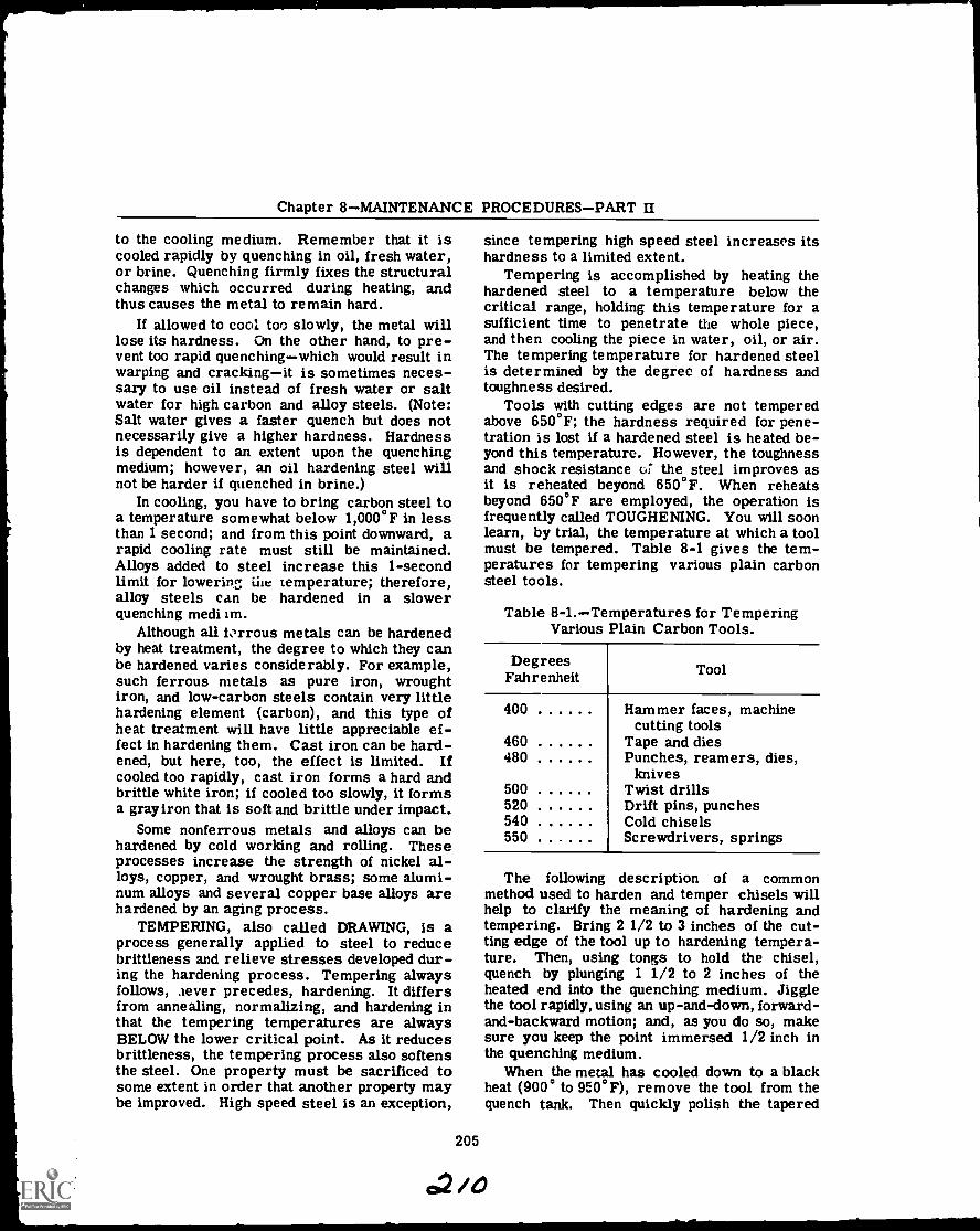
Chapter 8MAINTENANCE PROCEDURESPART II
to the cooling medium. Remember that it iscooled rapidly by quenching in oil, fresh water,or brine. Quenching firmly fixes the structuralchanges which occurred during heating, andthus causes the metal to remain hard.
If allowed to cool too slowly, the metal willlose its hardness. On the other hand, to pre-vent too rapid quenchingwhich would result inwarping and crackingit is sometimes neces-sary to use oil instead of fresh water or saltwater for high carbon and alloy steels. (Note:Salt water gives a faster quench but does notnecessarily give a higher hardness. Hardnessis dependent to an extent upon the quenchingmedium; however, an oil hardening steel willnot be harder if quenched in brine.)
In cooling, you have to bring carbon steel toa temperature somewhat below 1,000°F in lessthan 1 second; and from this point downward, arapid cooling rate must still be maintained.Alloys added to steel increase this 1-secondlimit for lowering iiie temperature; therefore,alloy steels can be hardened in a slowerquenching medi im.
Although all ic.rrous metals can be hardenedby heat treatment, the degree to which they canbe hardened varies considerably. For example,such ferrous metals as pure iron, wroughtiron, and low-carbon steels contain very littlehardening element (carbon), and this type ofheat treatment will have little appreciable ef-fect in hardening them. Cast iron can be hard-ened, but here, too, the effect is limited. Ifcooled too rapidly, cast iron forms a hard andbrittle white iron; if cooled too slowly, it formsa gray iron that is soft and brittle under impact.
Some nonferrous metals and alloys can behardened by cold working and rolling. Theseprocesses increase the strength of nickel al-loys, copper, and wrought brass; some alumi-num alloys and several copper base alloys arehardened by an aging process.
TEMPERING, also called DRAWING, is aprocess generally applied to steel to reducebrittleness and relieve stresses developed dur-ing the hardening process. Tempering alwaysfollows, aever precedes, hardening. It differsfrom annealing, normalizing, and hardening inthat the tempering temperatures are alwaysBELOW the lower critical point. As it reducesbrittleness, the tempering process also softensthe steel. One property must be sacrificed tosome extent in order that another property maybe improved. High speed steel is an exception,
205
since tempering high speed steel increases itshardness to a limited extent.
Tempering is accomplished by heating thehardened steel to a temperature below thecritical range, holding this temperature for asufficient time to penetrate the whole piece,and then cooling the piece in water, oil, or air.The tempering temperature for hardened steelis determined by the degree of hardness andtoughness desired.
Tools with cutting edges are not temperedabove 650°F; the hardness required for pene-tration is lost if a hardened steel is heated be-yond this temperature. However, the toughnessand shock resistance o: the steel improves asit is reheated beyond 650°F. When reheatsbeyond 650°F are employed, the operation isfrequently called TOUGHENING. You will soonlearn, by trial, the temperature at which a toolmust be tempered. Table 8-1 gives the tem-peratures for tempering various plain carbonsteel tools.
Table 8-1.Temperatures for TemperingVarious Plain Carbon Tools.
DegreesFahrenheit
400
460480
500520540550
Tool
Hammer faces, machinecutting tools
Tape and diesPunches, reamers, dies,
knivesTwist drillsDrift pins, punchesCold chiselsScrewdrivers, springs
The following description of a commonmethod used to harden and temper chisels willhelp to clarify the meaning of hardening andtempering. Bring 2 1/2 to 3 inches of the cut-ting edge of the tool up to hardening tempera-ture. Then, using tongs to hold the chisel,quench by plunging 1 1/2 to 2 inches of theheated end into the quenching medium. Jigglethe tool rapidly, using an up-and-down, forward-and-backward motion; and, as you do so, makesure you keep the point immersed 1/2 inch inthe quenching medium.
When the metal has cooled down to a blackheat (900° to 950°F), remove the tool from thequench tank. Then quickly polish the tapered
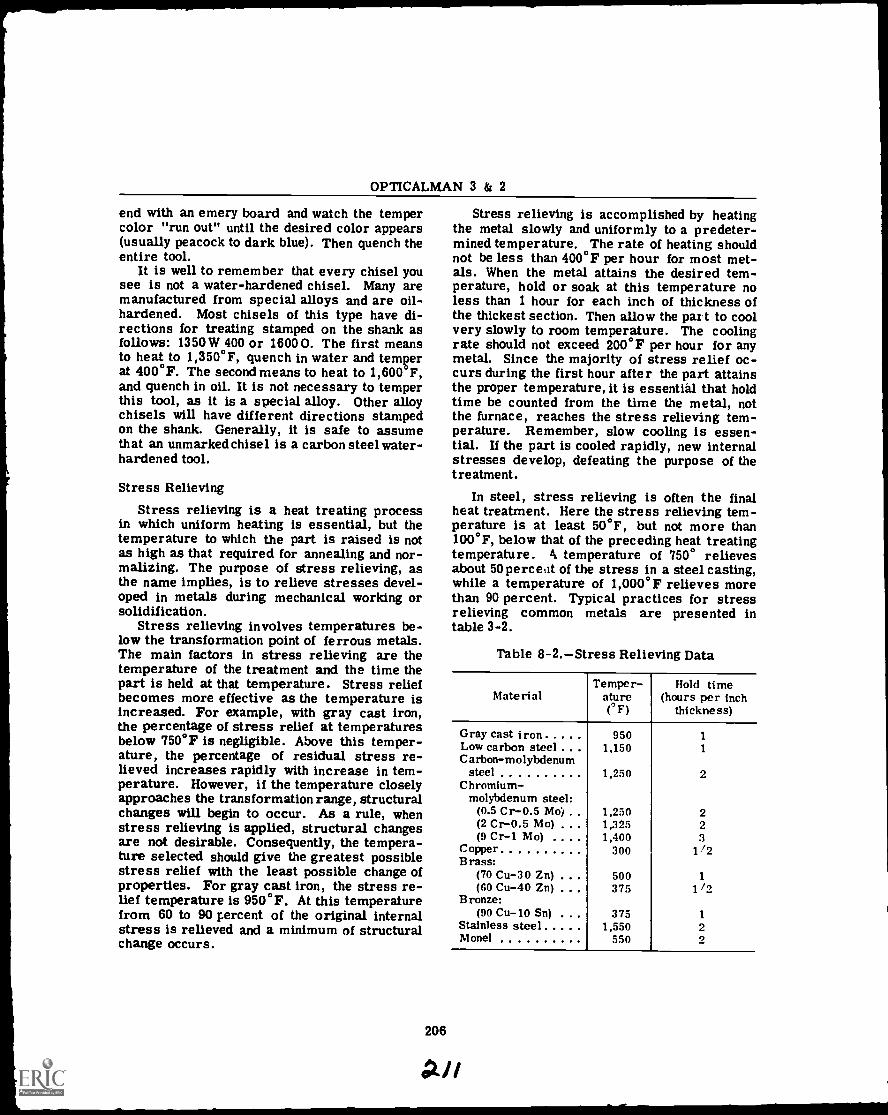
OPTICALMAN 3 & 2
end with an emery board and watch the tempercolor "run out" until the desired color appears(usually peacock to dark blue). Then quench theentire tool.
It is well to remember that every chisel yousee is not a water-hardened chisel. Many aremanufactured from special alloys and are oil-hardened. Most chisels of this type have di-rections for treating stamped on the shank asfollows: 1350W 400 or 1600 O. The first meansto heat to 1,350°F, quench in water and temperat 400°F. The second means to heat to 1,600 F,and quench in oil. It is not necessary to temperthis tool, as it is a special alloy. Other alloychisels will have different directions stampedon the shank. Generally, it is safe to assumethat an unmarked chisel is a carbon steel water-hardened tool.
Stress Relieving
Stress relieving is a heat treating processin which uniform heating is essential, but thetemperature to which the part is raised is notas high as that required for annealing and nor-malizing. The purpose of stress relieving, asthe name implies, is to relieve stresses devel-oped in metals during mechanical working orsolidification.
Stress relieving involves temperatures be-low the transformation point of ferrous metals.The main factors in stress relieving are thetemperature of the treatment and the time thepart is held at that temperature. Stress reliefbecomes more effective as the temperature isincreased. For example, with gray cast iron,the percentage of stress relief at temperaturesbelow 750° F is negligible. Above this temper-ature, the percentage of residual stress re-lieved increases rapidly with increase in tem-perature. However, if the temperature closelyapproaches the transformation range, structuralchanges will begin to occur. As a rule, whenstress relieving is applied, structural changesare not desirable. Consequently, the tempera-ture selected should give the greatest possiblestress relief with the least possible change ofproperties. For gray cast iron, the stress re-lief temperature is 950°F. At this temperaturefrom 60 to 90 percent of the original internalstress is relieved and a minimum of structuralchange occurs.
Stress relieving is accomplished by heatingthe metal slowly and uniformly to a predeter-mined temperature. The rate of heating shouldnot be less than 400°F per hour for most met-als. When the metal attains the desired tem-perature, hold or soak at this temperature noless than 1 hour for each inch of thickness ofthe thickest section. Then allow the part to coolvery slowly to room temperature. The coolingrate should not exceed 200°F per hour for anymetal. Since the majority of stress relief oc-curs during the first hour after the part attainsthe proper temperature, it is essential that holdtime be counted from the time the metal, notthe furnace, reaches the stress relieving tem-perature. Remember, slow cooling is essen-tial. If the part is cooled rapidly, new internalstresses develop, defeating the purpose of thetreatment.
In steel, stress relieving is often the finalheat treatment. Here the stress relieving tem-perature is at least 50°F, but not more than100°F, below that of the preceding heat treatingtemperature. k temperature of 750° relievesabout 50 percent of the stress in a steel casting,while a temperature of 1,000° F relieves morethan 90 percent. Typical practices for stressrelieving common metals are presented intable 3-2.
Table 8-2.Stress Relieving Data
MaterialTemper-
atureF)
Hold time(hours per inch
thickness)
Gray cast iron 950 1Low carbon steel . 1,150 1Carbon-molybdenum
steel 1,250 2Chromium-
molybdenum steel:(0.5 Cr-0.5 . . 1,250 2(2 Cr-0.5 Mo) . 1,225 2(9 Cr-1 Mo) 1,400 3
Copper 300 1 /2
Brass:(70 Cu-30 Zn) 500 1(60 Cu-40 Zn) . 375 I/0
Bronze:(90 Cu-10 Sn) . 375 1
Stainless steel 1,550 2Monel 550 2
206
II

CHAPTER 9
MACHINE TOOL OPERATION-PART I
Machine tool operation requires a knowledgeof certain mechanical principles that apply toall machine work. These are the principles ofCUTTING TOOLS, CUTTING SPEEDS, andFEEDS, and action of GEARS, SCREWS, andCAMS.
All of these principles are applied in theconstruction of machines and in the various ma-chine operations. The mechanical principlesmay be few, but there is no end to the methodsof application in machine tool work. This chap-ter is not written to give you the knowledge tobecome a machinist, but to give you additionalknowledge that will help you to become a betterOPTICALMAN. It has long been recognized thatopticaland mechanical problems are two phasesin the single problem of repairing opticalinstruments.
As an opticalman in the Navy, you will oftenbe working on vital instruments where replace-ment parts and special tools are not available.When this situation arises, a good opticalmanmust be prepared to manufacture the part ortool that is needed.
This chapter gives a description of the ma-chine tools common to optical shops and it willhelp you to gain a working knowledge of the ma-chining operations that you will be required toperform. First and foremost,you must remem-her that NO JOB IS SO IMPORTANT AND NOSERVICE IS SO URGENT THAT WE CANNOTTAKE TIME TO PERFORM OUR WORKSAFELY.
LATHES
An engine lathe such as the one shown in fig-ure 9-1, or one similar to it, is found in everyoptical shop, however small. It is used prin-cipally for turning, boring, facing, and threadcutting; but it may also be used for drilling,reaming, knurling, grinding, spinning, and springwinding. The work held in the engine lathe canbe revolved at a number of different speeds, andthe cutting tool can be accurately controlled byhand or power for longitudinal and cross feed.(Longitudinal feed is movement of the cutting
207
02a
tool parallel to the axis of the lathe; cross feedis movement of the cutting tool perpendicularto the axis of the lathe.)
Lathe size is determined by two measure-ments: (1) diameter of work it will swing overthe bed, and (2) length of the bed. For example,a 14-inch x 6-foot lathe will swing work up to14 inches in diameter, and has a bed 6 feet long.Engine lathes are built in various sizes, rangingfrom small bench lathes with a swing of 6 inchesto very large lathes for turning work of largediameter, such as large turbine rotors. Theaverage size of lathes found in optical shops is8 inches to 16 inches.
PRINCIPAL PARTS
To learn the operation of a lathe, you mustfirst become familiar with the names and func-tions of the principal parts. In studying theprincipal parts in detail, bear in mind that lathesof different manufacture differ somewhat in de-tails of construction, but all are built to pro-vide the same general functional principles. Asyou read the description of each part, find itslocation on the lathe by referring to figure 9-1,which is labeled for this purpose. For specificdetails on the features of construction andoperating techniques, refer to the manufac-turer's technical manual for the machine youare using.
Bed
The bed is the base or foundation of the work-ing parts of the lathe. The main features of itsconstruction are the ways which are formed onits upper surface and run the full length of thebed. Ways provide the means for maintainingthe tailstock and carriage, which slide on them,in alignment with the headstock, which ispermanently secured by bolts at one end (atoperator's left).
Figure 9-2 shows the ways of a typical lathe.The inverted. V-shaped ways 1, 3, and 4, and theflat way 2, are accurately machined parallel tothe axis of the spindle and to each other. The
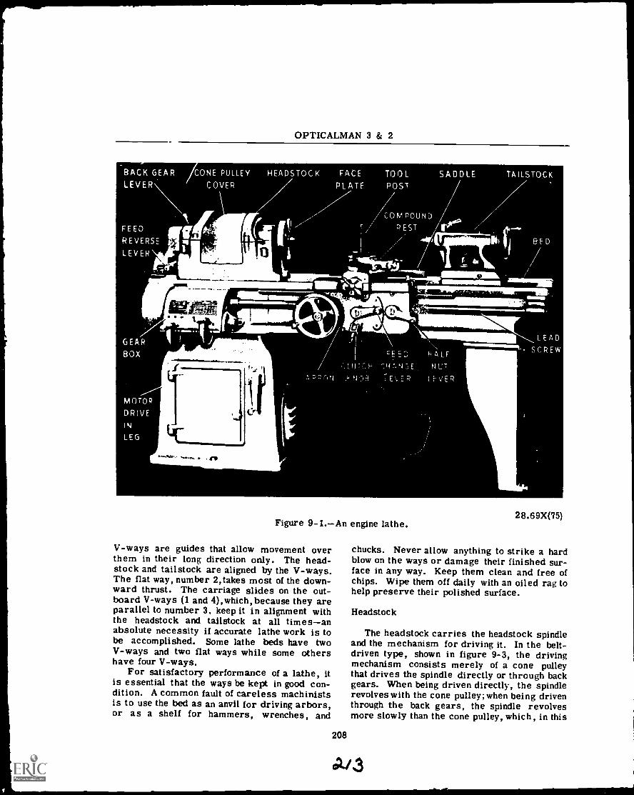
:
OPTICALMAN 3 & 2
I
0
II II XII
1.
Figure 9-1.An engine lathe.
V-ways are guides that allow movement overthem in their long direction only. The head-stock and tailstock are aligned by the V-ways.The flat way, number 2,takes most of the down-ward thrust. The carriage slides on the out-board V-ways (1 and 4),which, because they areparallel to number 3, keep it in alignment withthe headstock and tailstock at all timesanabsolute necessity if accurate lathe work is tobe accomplished. Some lathe beds have twoV-ways and two flat ways while some othershave four V-ways.
For satisfactory performance of a lathe, itis essential that the ways be kept in good con-dition. A common fault of careless machinistsis to use the bed as an anvil for driving arbors,or as a shelf for hammers, wrenches, and
208
0
: I
.21.1.11.1a.0010000101211ft_ Almon
28.69X(75)
chucks. Never allow anything to strike a hardblow on the ways or damage their finished sur-face in any way. Keep them clean and free ofchips. Wipe them off daily with an oiled rag tohelp preserve their polished surface.
Headstock
The headstock carries the headstock spindleand the mechanism for driving it. In the belt-driven type, shown in figure 9-3, the drivingmechanism consists merely of a cone pulleythat drives the spindle directly or through backgears. When being driven directly, the spindlerevolves with the cone pulley; when being driventhrough the back gears, the spindle revolvesmore slowly than the cone pulley, which, in this
A/3
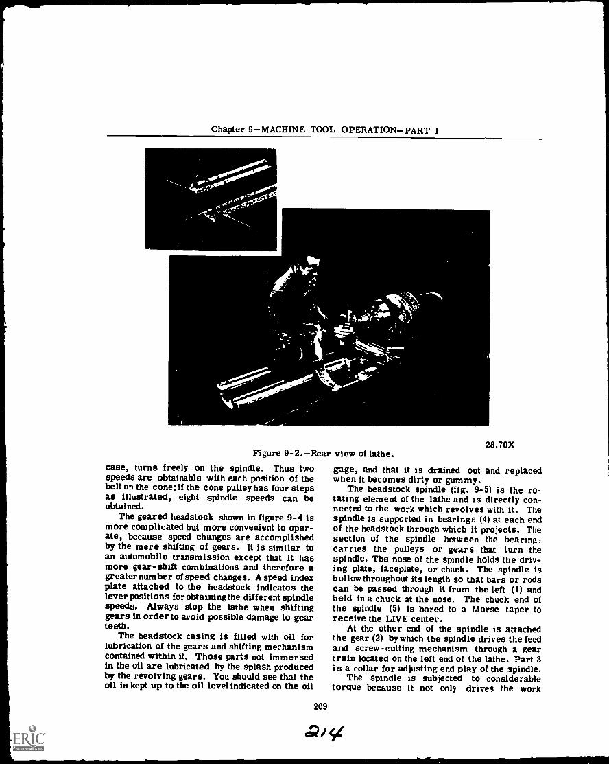
Chapter 9MACHINE TOOL OPERATIONPART I
Figure 9-2.Rear view of lathe.case, turns freely on the spindle. Thus twospeeds are obtainable with each position of thebelt on the cone; if the cone pulley has four stepsas illustrated, eight spindle speeds can beobtained.
The geared headstock shown in figure 9-4 ismore complicated but more convenient to oper-ate, because speed changes are accomplishedby the mere shifting of gears. It is similar toan automobile transmission except that it hasmore gear-shift combinations and therefore agreater number of speed changes. A speed indexplate attached to the headstock indicates thelever positions for obtaining the different spindlespeeds. Always stop the lathe when shiftinggears in order to avoid possible damage to gearteeth.
The headstock casing is filled with oil forlubrication of the gears and shifting mechanismcontained within it. Those parts not immersedin the oil are lubricated by the splash producedby the revolving gears. You should see that theoil is kept up to the oil level indicated on the oil
209
cP/
28.70X
gage, and that it is drained out and replacedwhen it becomes dirty or gummy.
The headstock spindle (fig. 9-5) is the ro-tating element of the lathe and is directly con-nected to the work which revolves with it. Thespindle is supported in bearings (4) at each endof the headstock through which it projects. Thesection of the spindle between the bearing.:carries the pulleys or gears that turn thespindle. The nose of the spindle holds the driv-ing plate, faceplate, or chuck. The spindle ishollow throughout its length so that bars or rodscan be passed through it from the left (1) andheld in a chuck at the nose. The chuck end ofthe spindle (5) is bored to a Morse taper toreceive the LIVE center.
At the other end of the spindle is attachedthe gear (2) by which the spindle drives the feedand screw-cutting mechanism through a geartrain located on the left end of the lathe. Part 3is a collar for adjusting end play of the spindle.
The spindle is subjected to considerabletorque because it not only drives the work
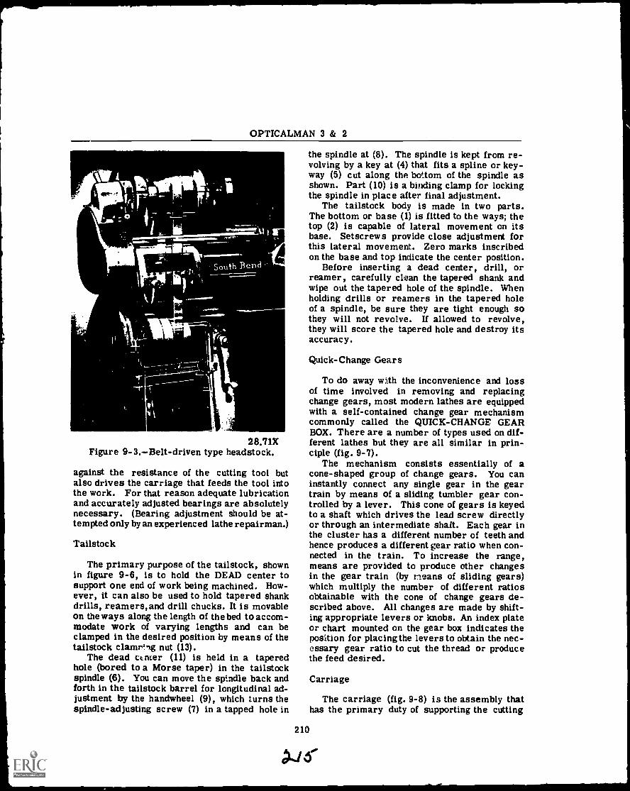
OPTICALMAN 3 & 2
et"
28.71XFigure 9-3.Belt-driven type headstock.
against the resistance of the cutting tool butalso drives the carriage that feeds the tool intothe work. For that reason adequate lubricationand accurately adjusted bearings are absolutelynecessary. (Bearing adjustment should be at-tempted only by an experienced lathe repairman.)
Tailstock
The primary purpose of the tailstock, shownin figure 9-6, is to hold the DEAD center tosupport one end of work being machined. How-ever, it can also be used to hold tapered shankdrills, reamers,and drill chucks. It is movableon the ways along the length of the bed to accom-modate work of varying lengths and can beclamped in the desired position by means of thetailstock clamring nut (13).
The dead ctnter (11) is held in a taperedhole (bored to a Morse taper) in the tailstockspindle (6). You can move the spindle back andforth in the tailstock barrel for longitudinal ad-justment by the handwheel (9), which turns thespindle-adjusting screw (7) in a tapped hole in
the spindle at (8). The spindle is kept from re-volving by a key at (4) that fits a spline or key-way (5) cut along the bottom of the spindle asshown. Part (10) is a binding clamp for lockingthe spindle in place after final adjustment.
The tailstock body is made in two parts.The bottom or base (1) is fitted to the ways; thetop (2) is capable of lateral movement on itsbase. Setscrews provide close adjustment forthis lateral movement. Zero marks inscribedon the base and top indicate the center position.
Before inserting a dead center, drill, orreamer, carefully clean the tapered shank andwipe out the tapered hole of the spindle. Whenholding drills or reamers in the tapered holeof a spindle, be sure they are tight enough sothey will not revolve. If allowed to revolve,they will score the tapered hole and destroy itsaccuracy.
Quick-Change Gears
To do away with the inconvenience and lossof time involved in removing and replacingchange gears, most modern lathes are equippedwith a self-contained change gear mechanismcommonly called the QUICK-CHANGE GEARBOX. There are a number of types used on dif-ferent lathes but they are all similar in prin-ciple (fig. 9-7).
The mechanism consists essentially of acone-shaped group of change gears. You caninstantly connect any single gear in the geartrain by means of a sliding tumbler gear con-trolled by a lever. This cone of gears is keyedto a shaft which drives the lead screw directlyor through an intermediate shaft. Each gear inthe cluster has a different number of teeth andhence produces a different gear ratio when con-nected in the train. To increase the range,means are provided to produce other changesin the gear train (by means of sliding gears)which multiply the number of different ratiosobtainable with the cone of change gears de-scribed above. All changes are made by shift-ing appropriate levers or knobs. An index plateor chart mounted on the gear box indicates theposition for placing the levers to obtain the nec-essary gear ratio to cut the thread or producethe feed desired.
210
Carriage
The carriage (fig. 9-8) is the assembly thathas the primary duty of supporting the cutting
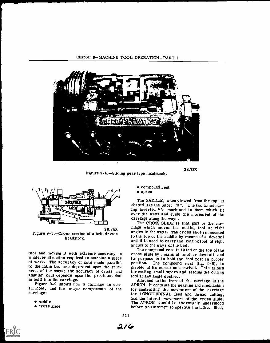
Chapter 9MACHINE TOOL OPERATIONPART I
.n
.1a
- _-:41 ',,.or.7"1,77.
1 114 3
AIL
4
28.72XFigure 9-4.Sliding gear type headstock.
28.74XFigure 9-5.Cross section of a belt-driven
headstock.
tool and moving it with extreme accuracy inwhatever direction required to machine a pieceof work. The accuracy of cuts made parallelto the lathe bed are dependent upon the true-ness of the ways; the accuracy of cross andangular cuts depends upon the precision thatis built into the carriage.
Figure 9-9 shows how a carriage is con-structed, and the major components of thecarriage:
saddlecross slide
compound restapron
The SADDLE, when viewed from the top, isshaped like the letter "H. The two arms hav-ing inverted V's machined in them which fitover the ways and guide the movement of thecarriage along the ways.
The CROSS SLIDE is that part of the car-riage which moves the cutting tool at rightangles to the ways. The cross slide is mountedto the top of the saddle by means of a dovetailand it is used to carry the cutting tool at rightangles to the ways of the bed.
The compound rest is fitted on the top of thecross slide by means of another dovetail, andits purpose is to hold the tool post in properposition. The compound rest (fig. 9-8), ispivoted at its center on a swivel. This allowsfor cutting small tapers and feeding the cuttingtool at any angle desired.
Attached to the front of the carriage is theAPRON. It contains the gearing and mechanismfor controlling the movement of the carriagefor LONGITUDINAL feed and thread cutting,and the lateral movement of the cross slide.The APRON should be thoroughly understoodbefore you attempt to operate the lathe. Study
211
A / 4
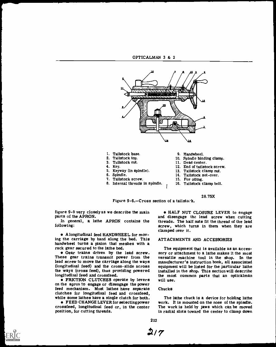
OPTICALMAN 3 & 2
1111111111)MIA W/71") W07),Y#n A 'a orh s i ,
PM N Ne. " .' , w x'm m .w . . ' 4 f i N .4Ik a ,
111 .2: 0,,H,I, II IN I,I MI;VIM.11.\1 \ NIINIMWIIIPelkiele 6.,NNV 1 . r7
/#0 MI 507#01,AM :ALVAN.111= IMI 4.aw,,&
1. Tailstock base. 9. Handwheel.2. Tailstock top. 10. Spindle binding clamp.3. Tailstock nut. 11. Dead center.4. Key. 12. End of tailstock screw.5. Keyway (in spindle). 13. Tailstock clamp nut.6. Spindle. 14. Tailstock set-over.7. Tailstock screw. 15. For oiling.8. Internal threads in spindle. 16. Tailstock clamp bolt.
28.75XFigure 9-6.Cross section of a tailstock.
figure 9-9 very closely as we describe the mainparts of the APRON.
In general, a lathe APRON contains thefollowing:
A longitudinal feed HANDWHEEL for mov-ing the carriage by hand along the bed. Thishandwheel turns a pinion that meshes with arack gear secured to the lathe bed.
Gear trains driven by the lead screw.These gear trains transmit power from thelead screw to move the carriage along the ways(longitudinal feed) and the cross-slide acrossthe ways (cross feed), thus providing poweredlongitudinal feed and crossfeed.
FRICTION CLUTCHES operate by leverson the apron to engage or disengage the powerfeed mechanism. Most lathes have separateclutches for longitudinal feed and crossfeed,while some lathes have a single clutch for both.
FEED CHANGE LEVER for selecting powercrossfeed, longitudinal feed or, in the centerposition, for cutting threads.
HALF NUT CLOSURE LEVER to engageand disengage the lead screw when cuttingthreads. The half nuts fit the thread of the leadscrew, which turns in them when they areclamped over it.
ATTACHMENTS AND ACCESSORIES
The equipment that is available as an acces-sory or attachment to a lathe makes it the mostversatile machine tool in the shop. In themanufacturer's instruction book, all associatedequipment will be listed for the particular latheinstalled in the shop. This sectionwill describethe most common parts that an opticalmanwill use.
Chucks
The lathe chuck is a device for holding lathework. It is mounted on the nose of the spindle.The work is held by jaws which can be movedin radial slots toward the center to clamp down
212
/7
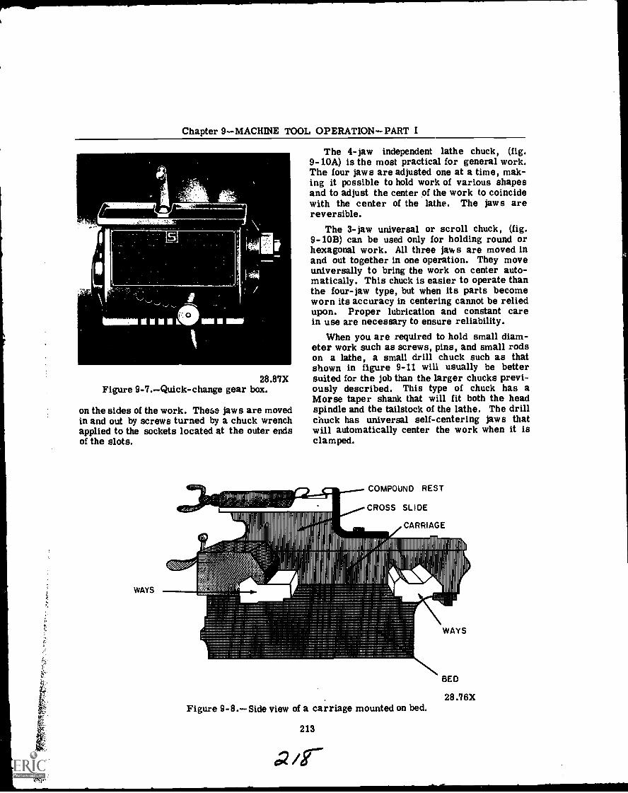
Chapter 9 MACHINE TOOL OPERATIONPART I
as.
(' 0
28.87XFigure 9-7.Quick-change gear box.
on the sides of the work. These jaws are movedin and out by screws turned by a chuck wrenchapplied to the sockets located at the outer endsof the slots.
WAYS
010,1!111111111111110!1111 111111111!
1111111111
11111Iiiiiiiiii
The 4-jaw independent lathe chuck, (fig.9-10A) is the most practical for general work.The four jaws are adjusted one at a time, mak-ing it possible to hold work of various shapesand to adjust the center of the work to coincidewith the center of the lathe. The jaws arereversible.
The 3-jaw universal or scroll chuck, (fig.9-10B) can be used only for holding round orhexagonal work. All three jaws are moved inand out together in one operation. They moveuniversally to bring the work on center auto-matically. This chuck is easier to operate thanthe four-jaw type, but when its parts becomeworn its accuracy in centering cannot be reliedupon. Proper lubrication and constant carein use are necessary to ensure reliability.
When you are required to hold small diam-eter work such as screws, pins, and small rodson a lathe, a small drill chuck such as thatshown in figure 9-11 will usually be bettersuited for the job than the larger chucks previ-ously described. This type of chuck has aMorse taper shank that will fit both the headspindle and the tailstock of the lathe. The drillchuck has universal self-centering jaws thatwill automatically center the work when it isclamped.
COMPOUND REST
CROSS SLIDE
CARRIAGE
1, ...h1,", I
Figure 9-8.Side view of a carriage mounted on bed.
213
WAYS
BED
28.76X

OPTICALMAN 3 & 2
CROSSSLIDE
COMPOUNDREST
TOOLPOST SADDLE
APRON
CLUTCH'KNOB
FEEDCHANGELEVER
HALFNUT
LEVER
28.69(75)XFigure 9-9.Front view of carriage assembly.
The drill chuck is used to hold center drillsand straight shank drills in the tailstock whenperforming drilling operations on a lathe.
Collets
Another way of accurately holding smallwork in a lathe is with the draw-in collet. Fig-ure 9-12 shows the collet assembled in placein the lathe spindle. The collet is a self-centering device that is very accurate and mostoften used for precision work in the opticalshop. The collet which holds the work is a splitcylinder with an outside taper that fits into amatching tapered closing sleeve and screws intothe threaded end of a hollow draw bar. Turn-ing the hardwheel of the hollow draw bar pullsthe collet into the tapered sleeve, thereby clos-ing the collet firmly around the work and cen-tering it in the head spindle. The draw colletis quick acting and the size of the center hole
28.90XFigure 9-10.A. Four-jaw chuck.
B. Three-jaw chuck.
determines the diameter of the work that canbe held. Collets are made with center holesizes ranging from 1/64 of an inch up, and grad-uated in 1/64-inch steps. The best results areobtained when the diameter of the work is thesame size as the dimension stamped on thecollet.
To ensure accuracy of the work when usingthe draw-in collet, it is important that the con-tact surfaces of the collet and closing sleeveare free of chips, dirt, and burrs.
214
All
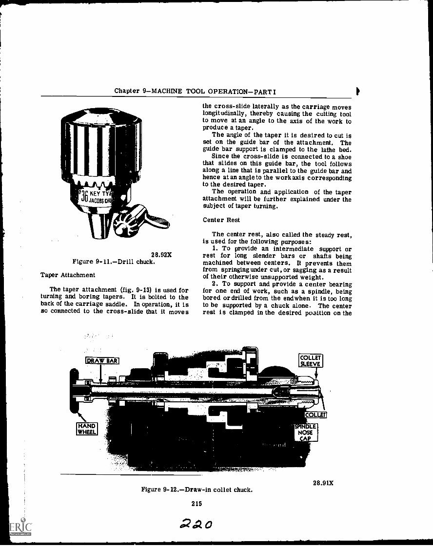
Chapter 9MACHINE TOOL OPERATIONPART I
rAAiloqg KEY TY
uU JACOBS CH
28.92XFigure 9-11.Drill chuck.
Taper Attachment
The taper attachment (fig. 9-13) is used forturning and boring tapers. It is bolted to theback of the carriage saddle. In operation, it isso connected to the cross-slide that it moves
!DRAW BAR
HANDWHEEL
the cross-slide laterally as the carriage moveslongitudinally, thereby causing the cutting toolto move at an angle to the axis of the work toproduce a taper.
The angle of the taper it is desired to cut isset on the guide bar of the attachment. Theguide bar support is clamped to the lathe bed.
Since the cross-slide is connected to a shoethat slides on this guide bar, the tool followsalong a line that is parallel to the guide bar andhence at an angle to the workaxis correspondingto the desired taper.
The operation and application of the taperattachment will be further explained under thesubject of taper turning.
Center Rest
The center rest, also called the steady rest,is used for the following purposes:
1. To provide an intermediate support orrest for long slender bars or shafts beingmachined between centers. It prevents themfrom springing under cut, or sagging as a resultof their otherwise unsupported weight.
2. To support and provide a center bearingfor one end of work, such as a spindle, beingbored or drilled from the endwhen it is too longto be supported by a chuck alone. The centerrest is clamped in the desired position on the
MK_
COLLETSLEEVE
.1.00,r,
COLLET
SPINDLENOSE
A
28.91XFigure 9-12.Draw-in collet chuck.
215
42420
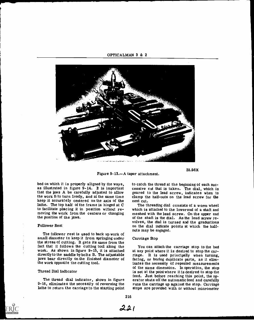
OPTICALMAN 3 & 2
Figure 9-13.A taper attachment.
bed on which it is properly aligned by the ways,as illustrated in figure 9-14. It is importantthat the jaws A be carefully adjusted to allowthe work B to turn freely, and at the same timekeep it accurately centered on the axis of thelathe. The top half of the frame is hinged at Cto facilitate placing it in position without re-moving the work from the centers or changingthe position of the jaws.
Follower Rest
The follower rest is used to back up work ofsmall diameter to keep it from springing underthe stress of cutting. It gets its name from thefact that it follows the cutting tool along thework. As shown in figure 9-15, it is attacheddirectly to the saddle by bolts B. The adjustablejaws bear directly on the finished diameter ofthe work opposite the cutting tool.
Thread Dial Indicator
The thread dial indicator, shown in figure9-16, eliminates the necessity of reversing thelathe to return the carriage to the starting point
216
ley
28.98X
to catch the thread at the beginning of each suc-cessive cut that is taken. The dial, which isgeared to the lead screw, indicates when toclamp the half-nuts on the lead screw for thenext cut.
The threading dial consists of a worm wheelwhich is attached to the lower end of a shaft andmeshed with the lead screw. On the upper endof the shaft is the dial. As the lead screw re-volves, the dial is turned and the graduationson the dial indicate points at which the half -nuts may be engaged.
Carriage Stop
You can attach the carriage stop to the bedat any point where it is desired to stop the car-riage. It is used principally when turning,facing, or boring duplicate parts, as it elim-inates the necessity of repeated measurementsof the same dimension. In operation, the stopis set at the point where it is desired to stop thefeed. Just before reaching this point, the op-erator shuts off the automatic feed and carefullyruns the carriage up against the stop. Carriagestops are provided with or without micrometer
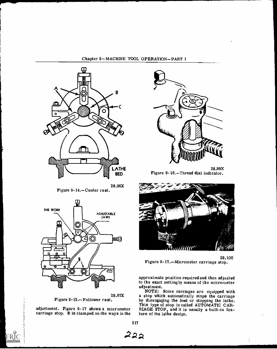
Chapter 9MACHINE TOOL OPERATIONPART I
Figure 9- 14.Center rest.
THE WORK
28.96X
ADJUSTABLEJAWS
28.97XFigure 9-15.Follower rest.
adjustment. Figure 9-17 shows a micrometercarriage stop. It is clamped on the ways in the
28.99XFigure 9- 16.Thread dial indicator.
217
v471/4
28.100Figure 9- 17.Micrometer carriage stop.
approximate position required and then adjustedto the exact setting by means of the micrometeradjustment.
NOTE: Some carriages are equipped witha stop which automatically stops the carriageby disengaging the feed or stopping the lathe.This type of stop is called AUTOMATIC CAR-RIAGE STOP, and it is usually a built-in fea-ture of the lathe design.
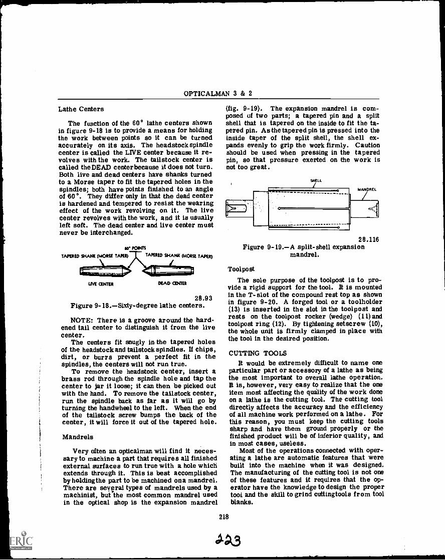
OPTICALMAN 3 & 2
Lathe Centers
The function of the 60° lathe centers shownin figure 9-18 is to provide a means for holdingthe work between points so it can be turnedaccurately on its axis. The headstock spindlecenter is called the LIVE center because it re-volves with the work. The tailstock center iscalled the DEAD center because it does not turn.Both live and dead centers have shanks turnedto a Morse taper to fit the tapered holes in thespindles; both have points finished to an angleof 60°. They differ only in that the dead centeris hardened and tempered to resist the wearingeffect of the work revolving on it. The livecenter revolves with the work, and it is usuallyleft soft. The dead center and live center mustnever be interchanged.
dr POINTS
TAPERED SHANK (MORSE TAPER)Tr TAPERED SHANK (MORSE TAPER)
LIVE man DEAD CENTER
28.93Figure 9-18.Sixty-degree lathe centers.
NOTE: There is a groove around the hard-ened tail center to distinguish it from the livecenter.
The centers fit snugly in the tapered holesof the headstock and tailstock spindles. If chips,dirt, or burrs prevent a perfect fit in thespindles, the centers will not run true.
To remove the headstock center, insert abrass rod through the spindle hole and tap thecenter to jar it loose; it can then be picked outwith the hand. To remove the tailstock center,run the spindle back as far as it will go byturning the handwheel to the left. When the endof the tailstock screw bumps the back of thecenter, it will force it out of the tapered hole.
Mandrels
Very often an opticalman will find it neces-sary to machine a part that requires all finishedexternal surfaces to run true with a hole whichextends through it. This is best accomplishedby holdingthe part to be machined ona mandrel.There are several types of mandrels used by amachinist, but the most common mandrel usedin the optical shop is the expansion mandrel
(fig. 9-19). The expansion mandrel is com-posed of two parts; a tapered pin and a splitshell that is tapered on the inside to fit the ta-pered pin. As the tapered pin is pressed into theinside taper of the split shell, the shell ex-pands evenly to grip the work firmly. Cautionshould be used when pressing in the taperedpin, so that pressure exerted on the work isnot too great.
SNELL
K
MANDREL
4.<1
28.116Figure 9-19.A split-shell expansion
mandrel.
Tool po st
The sole purpose of the toolpost is to pro-vide a rigid support for the tool. It is mountedin the T- slot of the compound rest top as shownin figure 9-20. A forged tool or a toolholder(13) is inserted in the slot in the toolpost andrests on the toolpost rocker (wedge) (11) andtoolpost ring (12). By tightening setscrew (10),the whole unit is firmly clamped in place withthe tool in the desired position.
218
CUTTING TOOLSIt would be extremely difficult to name one
particular part or accessory of a lathe as beingthe most important to overall lathe operation.It is, however, very easy to realize that the oneitem most affecting the quality of the work doneon a lathe is the cutting tool. The cutting tooldirectly affects the accuracy and the efficiencyof all machine work performed on a lathe. Forthis reason, you must keep the cutting toolssharp and have them ground properly or thefinished product will be of inferior quality, andin most cases, useless.
Most of the operations connected with oper-ating a lathe are automatic features that werebuilt into the machine when it was designed.The manufacturing of the cutting tool is not oneof these features and it requires that the op-erator have the knowledge to design the propertool and the skill to grind cuttingtools from toolblanks.
.11A3
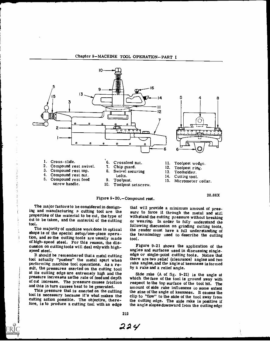
t
Chapter 9MACHINE TOOL OPERATIONPART I
1
13
I0
cThI----------
01-7-11.)0 0
00 GO IC GO SO 0
16
14
II
12
7
6
1. Cross-slide. 6. Crossfeed nut. 11. Toolpost wedge.2. Compound rest swivel. 7. Chip guard. 12. Toolpost ring.3. Compound rest top. 8. Swivel securing 13. Toolholder.4. Compound rest nut. bolts. 14. Cutting tool.5. Compound rest feed 9. Toolpost. 15. Micrometer collar.
screw handle. 10. Toolpost setscrew.
Figure 9-20.Compound rest.
The major factors to be considered in design-ing and manufacturing a cutting tool are theproperties of the material to be cut, the type ofcut to be taken, and the material of the cuttingtool.
The majority of machine work done in opticalshops is of the special setup/one-piece opera-tion, and so the cutting tools are usually madeof high-speed steel. For this reason, the dis-cussion on cutting tools will deal only with high-speed steel.
It should be remembered that a metal cuttingtool actually "pushes" the metal apart whenperforming machine tool operations. As a re-sult, the pressures exerted on the cutting toolat its cutting edge are extremely high and thepressure increases as the rate of feed and depthof cut increase. The pressure causes frictionand this in turn causes heat to be generated.
This pressure that is exerted on the cuttingtool is necessary because it's what makes thecutting action possible. The objective, there-fore, is to produce a cutting tool with an edge
219
28.88X
that will provide a minimum amount of pres-sure to force it through the metal and stillwithstand the cutting pressure without breakingor wearing. In order to fully understand thefollowing discussion on grinding cutting tools,the reader must have a full understanding ofthe terminology used to describe the cuttingtool.
Figure 9-21 shows the application of theangles and surfaces used in discussing single-edge or single-point cutting tools. Notice thatthere are two relief (clearance) angles and tworake angles, and the angle of keenness is formedby a rake and a relief angle.
Side rake (A of fig. 9-21) is the angle atwhich the face of the tool is ground away withrespect to the top surface of the tool bit. Theamount of side rake influences to some extentthe size of the angle of keenness. It causes theclip to "flow" to the side of the tool away fromthe cutting edge. The side rake is positive ifthe angle slopes downward from the cutting edge
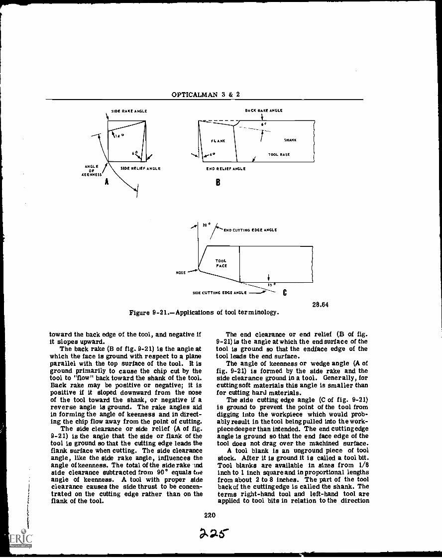
OPTICALMAN 3 & 2
SIDE RAKE ANGLE
ANGLEOF
KEENNESS
SIDE RELIEF ANGLE
NOSE
BACK RAKE ANGLE
Jr'
END RELIEF ANGLE
B
/END CUTTING EDGE ANGLE
TOOLFACE
I------_____ 15 0
SIDE CUTTING EDGE ANGLE --.0. ----
Figure 9-21.Applications of tool terminology.
toward the back edge of the tool, and negative ifit slopes upward.
The back rake (B of fig. 9-21) is the angle atwhich the face is ground with respect to a planeparallel with the top surface of the tool. It isground primarily to cause the chip cut by thetool to "flow" back toward the shank of the tool.Back rake may be positive or negative; it ispositive if it sloped downward from the noseof the tool toward the shank, or negative if areverse angle is ground. The rake angles aidin forming the angle of keenness and in direct-ing the chip flow away from the point of cutting.
The side clearance or side relief (A of fig.9-21) is the angle that the side or flank of thetool is ground so that the cutting edge leads theflank surface when cutting. The side clearanceangle, like the side rake angle, influences theangle of keenness. The total of the side rake Andside clearance subtracted from 90° equals tueangle of keenness. A tool with proper sideclearance causes the side thrust to be concen-trated on the cutting edge rather than on theflank of the tool.
220
C
28.64
The end clearance or end relief (B of fig.9-21) is the angle at which the end surface of thetool is ground so that the endface edge of thetool leads the end surface.
The angle of keenness or wedge angle (A offig. 9-21) is formed by the side rake and theside clearance ground in a tool. Generally, forcutting soft materials this angle is smaller thanfor cutting hard materials.
The side cutting edge angle (C of fig. 9-21)is ground to prevent the point of the tool fromdigging into the workpiece which would prob-ably result in the tool being pulled into the work-piece deeper than intended. The end cutting edgeangle is ground so that the end face edge of thetool does not drag over the machined surface.
A tool blank is an unground piece of toolstock. After it is ground it is called a tool bit.Tool blanks are available in sizes from 1/8inch to 1 inch square and in proportional lengthsfrom about 2 to 8 inches. The part of the toolback of the cutting edge is called the shank. Theterms right-hand tool and left-hand tool areapplied to tool bits in relation to the direction
Chapter 9MACHINE TOOL OPERATIONPART I
they move across the workpiece. If a tool cutswhile moving from left to right (as you see it,standing in front of the machine), it is a left-hand tool. A right-hand tool is just the opposite.
Figure 9-22 shows the most popular shapesof ground lathe tool cutter bits and their appli-cation. In the following paragraphs each of thetypes shown is described.
Turning
LEFT-HAND TURNING TOOL.This tool isground for machining work when fed from leftto right, as indicated in A, figure 9-22. Thecutting edge is on the right side of the tool andthe top of the tool slopes down away from thecutting edge.
ROUND-NOSED TURNING TOOL.This toolis for general all-round machine work and isused for taking light roughing cuts and finishingcuts. Usually,the top of the cutter bit is groundwith side rake so that the tool may be fed fromright to Left. Sometimes this cutter bit Is groundflat on top so that the tool may be fed in eitherdirection (B, fig. 9-22).
RIGHT-HAND TURNING TOOL.This is justthe opposite of the left-hand turning tool and isdesigned to cut when fed from right to left (C,fig. 9-22). The cutting edge is on the left side.This is an ideal tool for taking roughing cutsand for general all-round machine work.
LEFT-HAND FACING TOOL.This tool isintended for facing on the left-hand side of thework, as shown in D, figure 9-22. The directionof feed is away from the lathe center. The cut-ting edge is on the right-hand side of the tooland the point of the tool is sharp to permitmachining a square corner.
RIGHT-HAND FACING TOOL.This tool isjust the opposite of the left-hand facing tool andis intended for facing the right end of the workand for machining the right side of a shoulder.(See F, fig. 9 -22.)
Threading
THREADING TOOL. The point of the thread-ing tool is ground to a 60° included angle formachining V-form screw threads (E, fig. 9-22).Usually, the top of the tool is ground flat andthere is clearance on both sides of the tool sothat it will cut on both sides.
INTERNAL-THREADING TOOL.Theinternal-threading (INSIDE-THREADING) toolis the same as the threading tool in E, figure
9-22, except that it is usually much smaller.Boring and internal-threading tools may re-quire larger relief angles when used in smalldiameter holes.
Parting
SQUARE-NOSED PARTING (CUT-OFF)TOOL.The principal cutting edge of this toolis on the front. (See G, fig. 9-22.) Both sidesof the tool must have sufficient clearance toprevent binding and should be ground slightlynarrower at the back than at the cutting edge.This tool is convenient for machining necks,grooves, squaring corners, and for cutting off.
Boring
BORING TOOL.The boring tool is usuallyground the same shape as the left-hand turningtool so that the cutting edge is on the front sideof the cutter bit and may be fed in toward theheadstock.
The contour of a cutting tool is formed bythe side cutting edge angle and the end cuttingedge angle of the tool. (Parts A through G offig. 9-22 illustrate the recommended contour ofseveral types of tools.) There are no definiteguidelines on either the form or the includedangle of the contour of pointed tool bits. Eachmachinist usually forms the contour as he pre-fers. For roughing cuts, it is recommended thatthe included angle of the contour of pointed bitsbe made as large as possible and still provideclearance on the trailing side or end edge. Toolsfor threading, facing between centers, and part-ing have specific shapes because of the form ofthe machined cut or the setup used.
The materials being machined and the ma-chining technique used limit the angles of a toolbit. When grinding the angles, however, con-sideration must be given also to the type oftoolholder and the position of the tool withrespect to the axis of the workpiece. Theangular offset and the angular vertical rise ofthe tool seat in a standard lathe toolholderaffects the cutting edge angle and the endclearance angle of a tool when it is set up formachining. The position of the point of the toolbit with respect to the axis of the workpiece,whether higher, lower, or on center, changesthe amount of front clearance. Figure 9-23 showssome of the common toolholders used in lathework. Notice the angles at which the tool bitsset in the various holders. These angles must
221
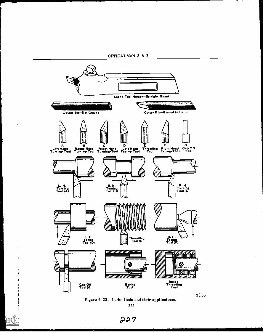
OPTICALMAN 3 & 2
Cutter BitNot Ground
Lathe Tool HolderStraight Shank
Cutter BitGround to Form
ALeft Hand Round Nose Right Hand Left Hand Threading Right Hand Cut-Off
Turning-Tool Turning-Tool Turning-Tool Facing-Tool Tool Facing-Tool Tool
L. H.TurningTool (A)
R. N.TurnIn_gTool (B)
R. H.TurningTool (C)
L. H.Facing
Tool (D)Threading
Tool (E)R. H.FacingTool (F)
Cut-OffTool (G)
BoringTool
Ins deThreading
Tool
Figure 9-22.Lathe tools and their applications.222
?A7
28.66
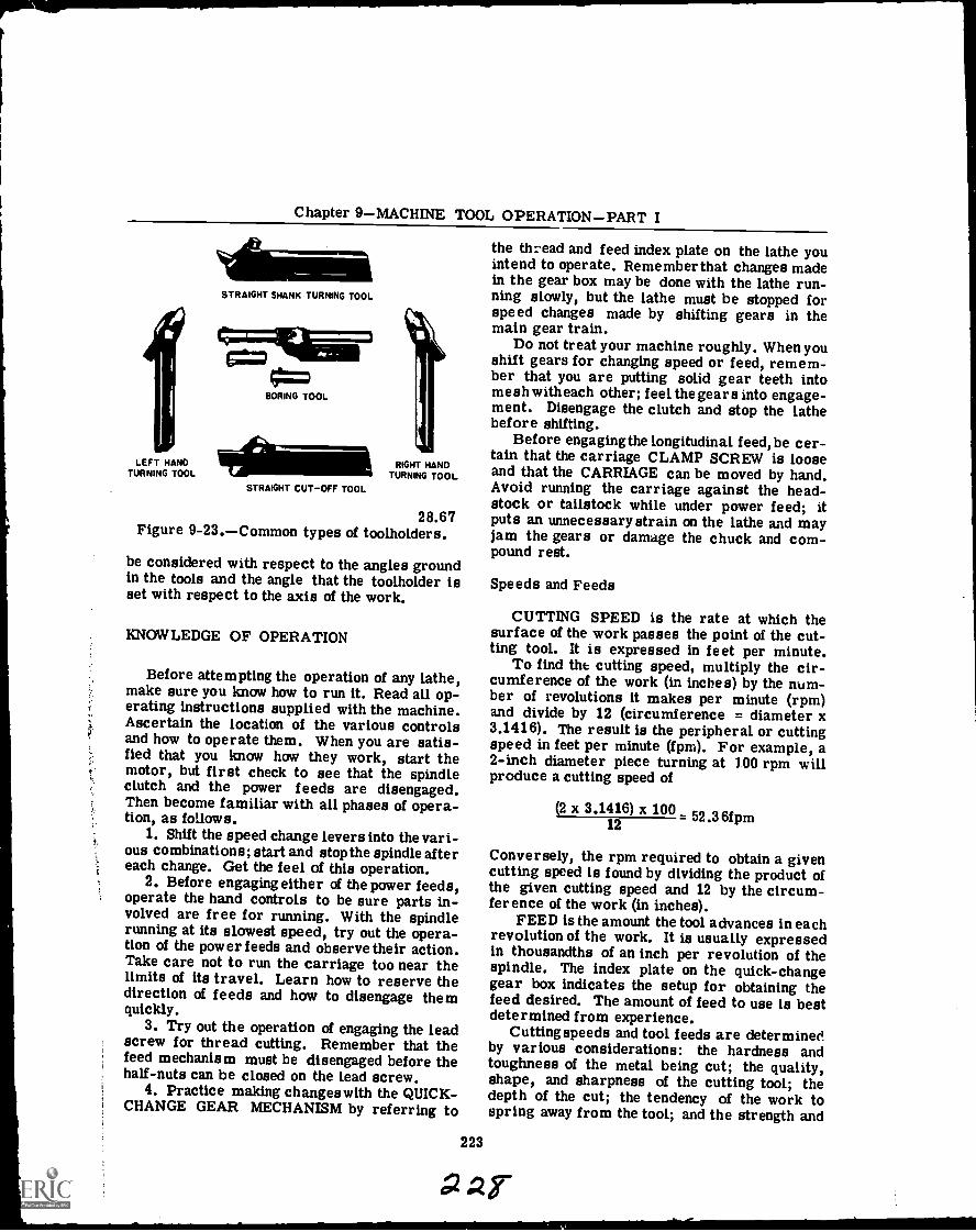
Chapter 9MACHINE TOOL OPERATIONPART I
LEFT HANDTURNING TOOL
STRAIGHT SHANK TURNING TOOL
BORING TOOL
STRAIGHT CUT -OFF TOOL
RIGHT HANDTURNING TOOL
28.67Figure 9-23.Common types of toolholders.
be considered with respect to the angles groundin the tools and the angle that the toolholder isset with respect to the axis of the work.
KNOWLEDGE OF OPERATION
Before attempting the operation of any lathe,make sure you know how to run it. Read all op-erating instructions supplied with the machine.Ascertain the location of the various controlsand how to operate them. When you are satis-fied that you know how they work, start themotor, but first check to see that the spindleclutch and the power feeds are disengaged.Then become familiar with all phases of opera-tion, as follows.
1. Shift the speed change levers into the vari-ous combinations; start and stop the spindle aftereach change. Get the feel of this operation.
2. Before engaging either of the power feeds,operate the hand controls to be sure parts in-volved are free for running. With the spindlerunning at its slowest speed, try out the opera-tion of the power feeds and observe their action.Take care not to run the carriage too near thelimits of its travel. Learn how to reserve thedirection of feeds and how to disengage themquickly.
3. Try out the operation of engaging the leadscrew for thread cutting. Remember that thefeed mechanism must be disengaged before thehalf-nuts can be closed on the lead screw.
4. Practice making changes with the QUICK-CHANGE GEAR MECHANISM by referring to
the thread and feed index plate on the lathe youintend to operate. Remember that changes madein the gear box may be done with the lathe run-ning slowly, but the lathe must be stopped forspeed changes made by shifting gears in themain gear train.
Do not treat your machine roughly. When youshift gears for changing speed or feed, remem-ber that you are putting solid gear teeth intomesh with each other; feel the gears into engage-ment. Disengage the clutch and stop the lathebefore shifting.
Before engaging the longitudinal feed,be cer-tain that the carriage CLAMP SCREW is looseand that the CARRIAGE can be moved by hand.Avoid running the carriage against the head-stock or tailstock while under power feed; itputs an unnecessary strain on the lathe and mayjam the gears or damage the chuck and com-pound rest.
Speeds and Feeds
223
CUTTING SPEED is the rate at which thesurface of the work passes the point of the cut-ting tool. It is expressed in feet per minute.
To find tilt cutting speed, multiply the cir-cumference of the work (in inches) by the num-ber of revolutions it makes per minute (rpm)and divide by 12 (circumference = diameter x3.1416). The result is the peripheral or cuttingspeed in feet per minute (fpm). For example, a2-inch diameter piece turning at 100 rpm willproduce a cutting speed of
(2 x 3.1416) x 100 52.36f12
Conversely, the rpm required to obtain a givencutting speed is found by dividing the product ofthe given cutting speed and 12 by the circum-ference of the work (in inches).
FEED is the amount the tool advances in eachrevolution of the work. It is usually expressedin thousandths of an inch per revolution of thespindle. The index plate on the quick-changegear box indicates the setup for obtaining thefeed desired. The amount of feed to use is bestdetermined from experience.
Cutting speeds and tool feeds are determinedby various considerations: the hardness andtoughness of the metal being cut; the quality,shape, and sharpness of the cutting tool; thedepth of the cut; the tendency of the work tospring away from the tool; and the strength and
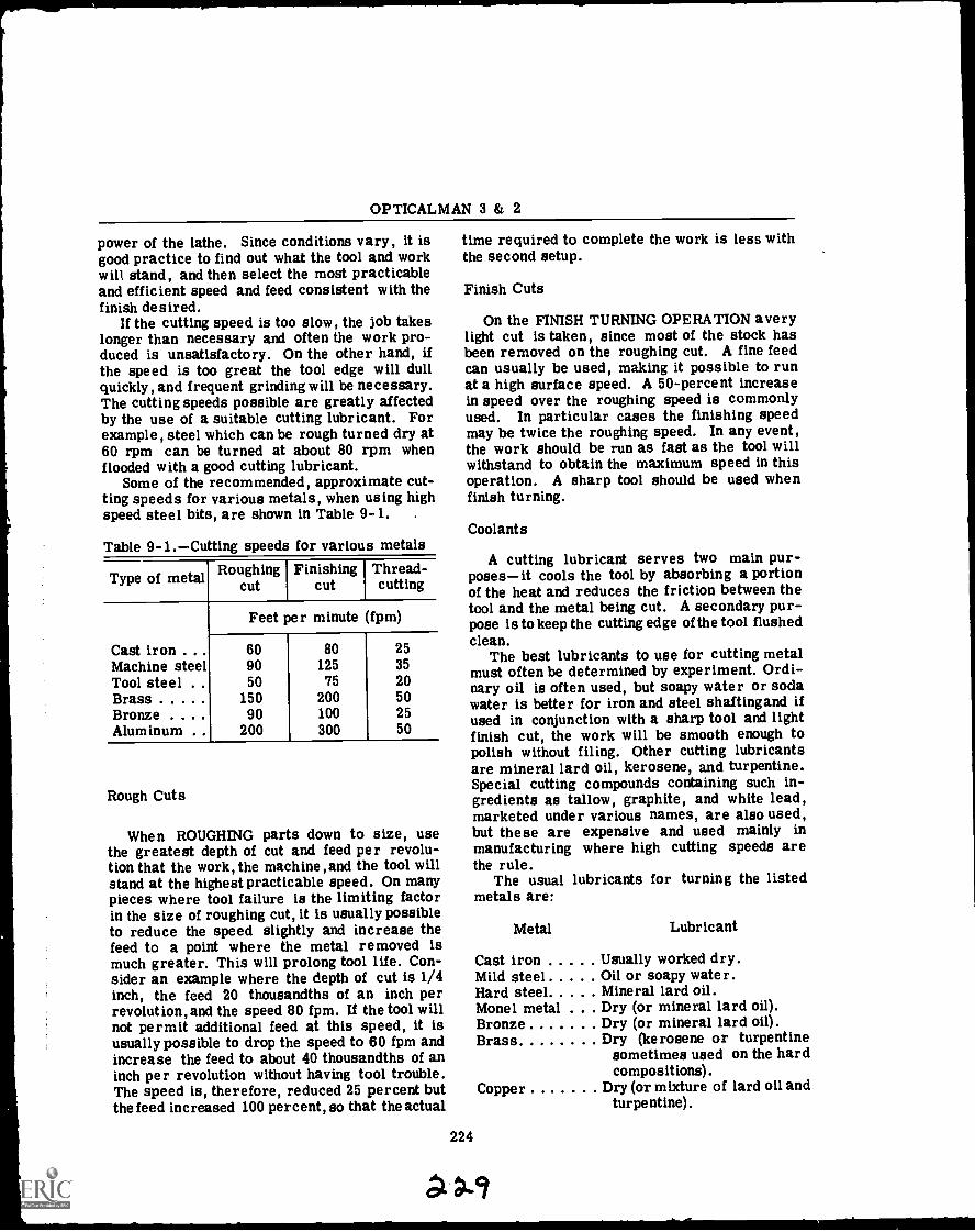
OPTICALMAN 3 & 2
power of the lathe. Since conditions vary, it isgood practice to find out what the tool and workwill stand, and then select the most practicableand efficient speed and feed consistent with thefinish desired.
If the cutting speed is too slow, the job takeslonger than necessary and often the work pro-duced is unsatisfactory. On the other hand, ifthe speed is too great the tool edge will dullquickly, and frequent grinding will be necessary.The cutting speeds possible are greatly affectedby the use of a suitable cutting lubricant. Forexample, steel which can be rough turned dry at60 rpm can be turned at about 80 rpm whenflooded with a good cutting lubricant.
Some of the recommended, approximate cut-ting speeds for various metals, when using highspeed steel bits, are shown in Table 9-1. .
Table 9-1.Cutting speeds for various metals
Type of metal Roughingcut
Finishingcut
Thread-cutting
Feet per minute (fpm)
Cast iron . . . 60 80 25Machine steel 90 125 35
Tool steel 50 75 20Brass 150 200 50Bronze . . . . 90 100 25Aluminum 200 300 50
Rough Cuts
When ROUGHING parts down to size, usethe greatest depth of cut and feed per revolu-tion that the work, the machine , and the tool willstand at the highest practicable speed. On manypieces where tool failure is the limiting factorin the size of roughing cut, it is usually possibleto reduce the speed slightly and increase thefeed to a point where the metal removed ismuch greater. This will prolong tool life. Con-sider an example where the depth of cut is 1/4inch, the feed 20 thousandths of an inch perrevolution, and the speed 80 fpm. If the tool willnot permit additional feed at this speed, it isusually possible to drop the speed to 60 fpm andincrease the feed to about 40 thousandths of aninch per revolution without having tool trouble.The speed is, therefore, reduced 25 percent butthe feed increased 100 percent, so that the actual
time required to complete the work is less withthe second setup.
Finish Cuts
On the FINISH TURNING OPERATION averylight cut is taken, since most of the stock hasbeen removed on the roughing cut. A fine feedcan usually be used, making it possible to runat a high surface speed. A 50-percent increasein speed over the roughing speed is commonlyused. In particular cases the finishing speedmay be twice the roughing speed. In any event,the work should be run as fast as the tool willwithstand to obtain the maximum speed in thisoperation. A sharp tool should be used whenfinish turning.
Coolants
A cutting lubricant serves two main pur-posesit cools the tool by absorbing a portionof the heat and reduces the friction between thetool and the metal being cut. A secondary pur-pose is to keep the cutting edge of the tool flushedclean.
The best lubricants to use for cutting metalmust often be determined by experiment. Ordi-nary oil is often used, but soapy water or sodawater is better for iron and steel shaftingand ifused in conjunction with a sharp tool and lightfinish cut, the work will be smooth enough topolish without filing. Other cutting lubricantsare mineral lard oil, kerosene, and turpentine.Special cutting compounds containing such in-gredients as tallow, graphite, and white lead,marketed under various names, are also used,but these are expensive and used mainly inmanufacturing where high cutting speeds arethe rule.
The usual lubricants for turning the listedmetals are:
224
Metal Lubricant
Cast iron Usually worked dry.Mild steel Oil or soapy water.Hard steel Mineral lard oil.Monel metal . Dry (or mineral lard oil).Bronze Dry (or mineral lard oil).Brass Dry (kerosene or turpentine
sometimes used on the hardcompositions).
Copper Dry (or mixture of lard oil andturpentine).
Chapter 9MACHINE TOOL OPERATIONPART IMetal Lubricant
Babbitt Dry (or mixture of lard oil andkerosene).
Aluminum Dry (or kerosene or mixtureof lard oil and kerosene).
For threading,a lubricant is more importantthan for straight turning. Mineral lard oil isrecommended for threading in all steels andcast iron, kerosene mixed with oil for alumi-num, white lead mixed with oil (to the consist-ency of glue) for Monel metal, and kerosene orturpentine for brass compositions.
Maintenance
Maintenance is an important part of opera-tional procedure for lathes. The first requisiteis PROPER LUBRICATION. Make it a point tooil your lathe daily where oil holes are pro-vided. Oil the ways dailynot only for lubrica-tion but to protect their scraped surfaces. Oilthe lead screw often while it is in use, this isnecessary to preserve its accuracy, for a wornlead screw lacks precision in thread cutting.Make sure the headstock is filled up to the oillevel; drain out and replace the oil when it be-comes dirty or gummy. If your lathe is equippedwith an automatic oiling system for some parts,make sure all those parts are getting oil. Makeit a habit to CHECK frequently for lubrication ofall moving parts.
Do not neglect the motor just because it maybe out of sight; check its LUBRICATION. If itdoes not run properly, notify the Electrician'sMate whose duty it is to care for it. He willcooperate with you to keep it in good condition.Ina machine that has a belt drive from the motorto the lathe, avoid getting oil or grease on thebelt when oiling the lathe or motor.
Keepyour lathe CLEAN. A clean and orderlymachine is an indication of a good mechanic.Dirt and chips on the ways, on the lead screw,and on the crossfeed screws will cause seriouswear and impair the accuracy of the machine.
Never put wrenches, files, or other tools onthe ways. If you must keep tools on the bed, aboard should be provided to protect the finishedsurfaces of the ways.
Never use the bed or carriage as an anvil;remember that the lathe is a precision machineand nothing must be allowed to destroy itsaccuracy.
LATHE OPERATION
The basic function of a lathe is the removalof metal, by means of a suitable cutting tool,from a piece of vr,rk which is securely sup-ported and ma& A.) revolve. This basic func-tion is applied to general lathe operations forstraight turning, taper turning, boring, facing,drilling, and thread cutting.
The wide range of operations that can beperformed on a lathe make it the most valuablemachine tool available. Up to this section, youhave stu.lied the construction of a lathe, theaccessories, and the various tools used on it.Now eta reader will be given the additional in-formation needed to combine the tools and themachinery for effective applications.
It is important that you study the blueprintof the piece to be manufactured before you beginmachining. Check over the dimensions and notethe points or surfaces from which they are laidout. Plan the steps of your work in advance inorder to determine the best method of proce-dure. Be sure from the overall dimensions thatthe stock you intend to use is large enough forthe job.
225
Mounting Work
Accurate work cannot be performed if workis improperly mount ed. Requirements forproper mounting are:
1. The work centerline must be accuratelycenteredwith the axis of the lathe spindle.
2. The work must be rigidly held while be-ing turned.
3. The work must not be sprung out of shapeby the holding device.
4. The work must be adequately supportedagainst any sagging caused by its ownweight and against springing caused bythe action of the cutting tool.
There are four general methods of holdingwork in the lathe: (1) between centers, (2) on amandrel, (3) in a chuck, and (4) on a faceplate.Work may also be clamped to the carriage forboring and milling; the boring bar or millingcutter is held and driven by the headstockspindle.
CENTERING THE WORK.To center fin-ished round stock such as drill rod or cold-rolled steel, where the ends are to be turnedand must be concentric with the unturned body,the work can be held on the head spindle in auniversal chuck or a draw-in collet chuck. If
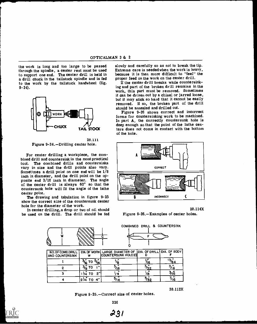
OPTICALMAN 3 & 2
the work is long and too large to be passedthrough the spindle, a center rest must be usedto support one end. The center drill is held ina drill chuck in the tailstock spindle and is fedto the work by the tailstock handwheel (fig.9 -24).
28.111Figure 9-24.Drilling center hole.
For center drilling a workpiece, the com-bined drill and countersink is the most practicaltool. The combined drills and countersinksvary in size and the drill points also vary.Sometimes a drill point on one end will be 1/8inch in diameter, and the drill point on the op-posite end 3/16 inch in diameter. The angleof the center drill is always 60° so that thecountersunk hole will fit the angle of the lathecenter point.
The drawing and tabulation in figure 9-25show the correct size of the countersunk centerhole for the diameter of the work.
In center drilling, a drop or two of oil shouldbe used on the drill. The drill should be fed
1
C
slowly and carefully so as not to break the tip.Extreme care is needed when the work is heavy,because it is then more difficult to "feel" theproper feed on the work on the center drill.
If the center drill breaks while countersink-ing and part of the broken drill remains in thework, this part must be removed. Sometimesit can be driven out by a chisel or jarred loose,but it may stick so hard that it cannot be easilyremoved. If so, the broken part of the drillshould be annealed and drilled out.
Figure 9-26 shows correct and incorrectforms for countersinking work to be machined.In part A, the correctly countersunk hole isdeep enough so that the point of the lathe cen-ters does not come in contact with the bottomof the hole.
28.114XFigure 9-26.Examples of center holes.
COMBINED DRILL a COUNTERSINK
NO.OFCOMB.DRILLAND COUNTERSINK
DIA.OF WORKW
LARGE DIAMETER OFCOUNTERSUNK HOLE(C)
DIA. OF DRILLD
DIA. OF BODYF
1 341 T 0 5/1181 1/8"
3 it/16
I it/16
3 II/32
13/643 11462 3/" TO I "8
3 I 1/4 TO 2" I/ 41 l/8 3/I6
41 11
2 /4 TO 4" 5/16sl
/32 7/16
28.113XFigure 9-25.Correct size of center holes.
226
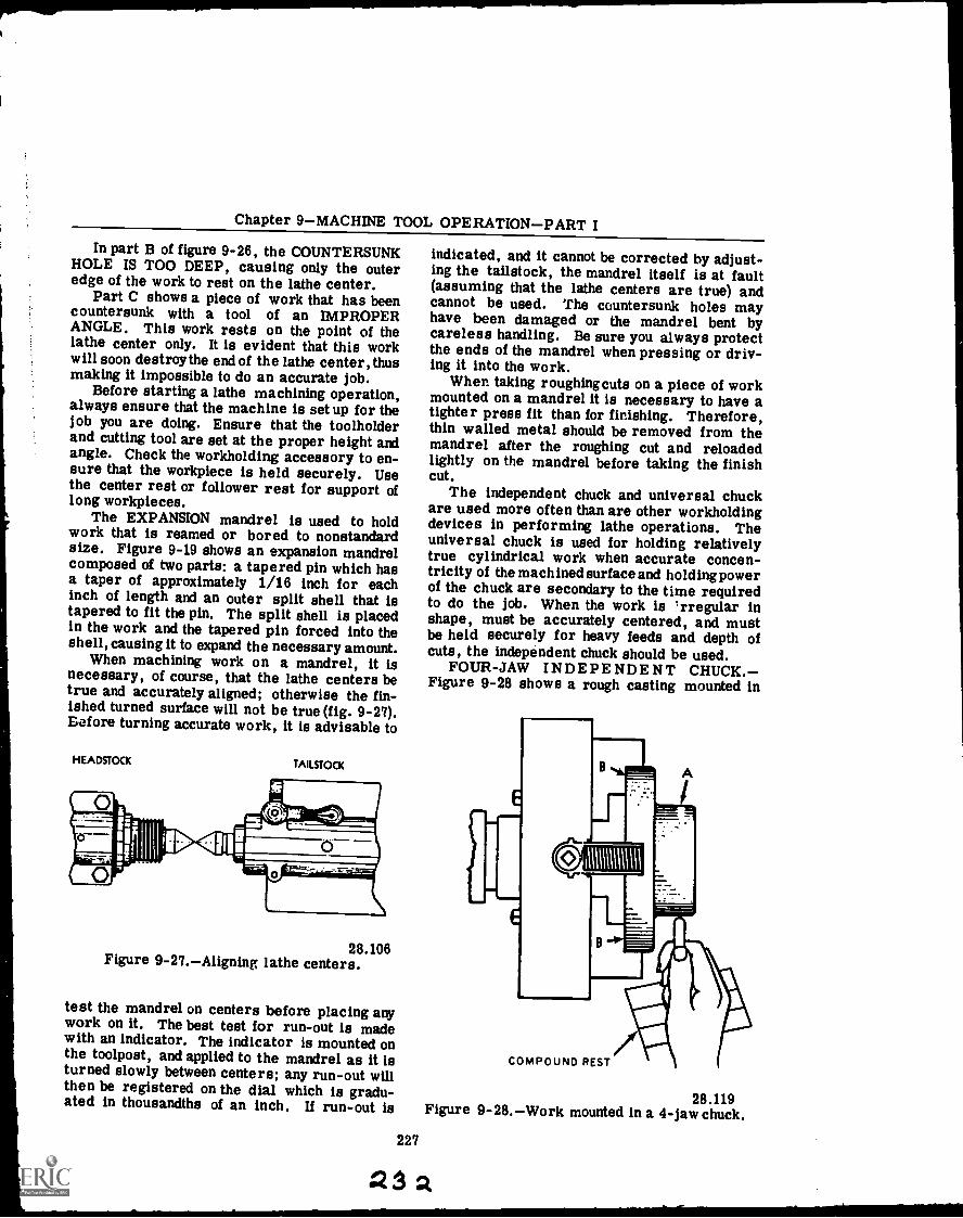
Chapter 9MACHINE TOOL OPERATIONPART I
In part B of figure 9-26, the COUNTERSUNKHOLE IS TOO DEEP, causing only the outeredge of the work to rest on the lathe center.
Part C shows a piece of work that has beencountersunk with a tool of an IMPROPERANGLE. This work rests on the point of thelathe center only. It is evident that this workwill soon destroy the end of the lathe center, thusmaking it impossible to do an accurate job.
Before starting a lathe machining operation,always ensure that the machine is set up for thelob you are doing. Ensure that the toolholderand cutting tool are set at the proper height andangle. Check the workholding accessory to en-sure that the workpiece is held securely. Usethe center rest or follower rest for support oflong workpieces.
The EXPANSION mandrel is used to holdwork that is reamed or bored to nonstandardsize. Figure 9-19 shows an expansion mandrelcomposed of two parts: a tapered pin which hasa taper of approximately 1/16 inch for eachinch of length and an outer split shell that istapered to fit the pin. The split shell is placedin the work and the tapered pin forced into theshell, causing it to expand the necessary amount.
When machining work on a mandrel, it isnecessary, of course, that the lathe centers betrue and accurately aligned; otherwise the fin-ished turned surface will not be true (fig. 9-27).Before turning accurate work, it is advisable to
HEADSTOCK TAILSTOCK
28.106Figure 9-27.Aligning lathe centers.
test the mandrel on centers before placing anywork on it. The best test for run-out is madewith an indicator. The indicator is mounted onthe toolpost, and applied to the mandrel as it isturned slowly between centers; any run-out willthen be registered on the dial which is gradu-ated in thousandths of an inch. If run-out is
indicated, and it cannot be corrected by adjust-ing the tailstock, the mandrel itself is at fault(assuming that the lathe centers are true) andcannot be used. The countersunk holes mayhave been damaged or the mandrel bent bycareless handling. Be sure you always protectthe ends of the mandrel when pressing or driv-ing it into the work.
When taking roughing cuts on a piece of workmounted on a mandrel it is necessary to have atighter press fit than for finishing. Therefore,thin walled metal should be removed from themandrel after the roughing cut and reloadedlightly on the mandrel before taking the finishcut.
The independent chuck and universal chuckare used more often than are other workholdingdevices in performing lathe operations. Theuniversal chuck is used for holding relativelytrue cylindrical work when accurate concen-tricity of the machined surface and holdingpowerof the chuck are secondary to the time requiredto do the job. When the work is trregular inshape, must be accurately centered, and mustbe held securely for heavy feeds and depth ofcuts, the independent chuck should be used.
FOUR-JAW INDEPENDENT CHUCK.Figure 9-28 shows a rough casting mounted in
227
1
COMPOUND REST
28.119Figure 9-28.Work mounted in a 4-jaw chuck.
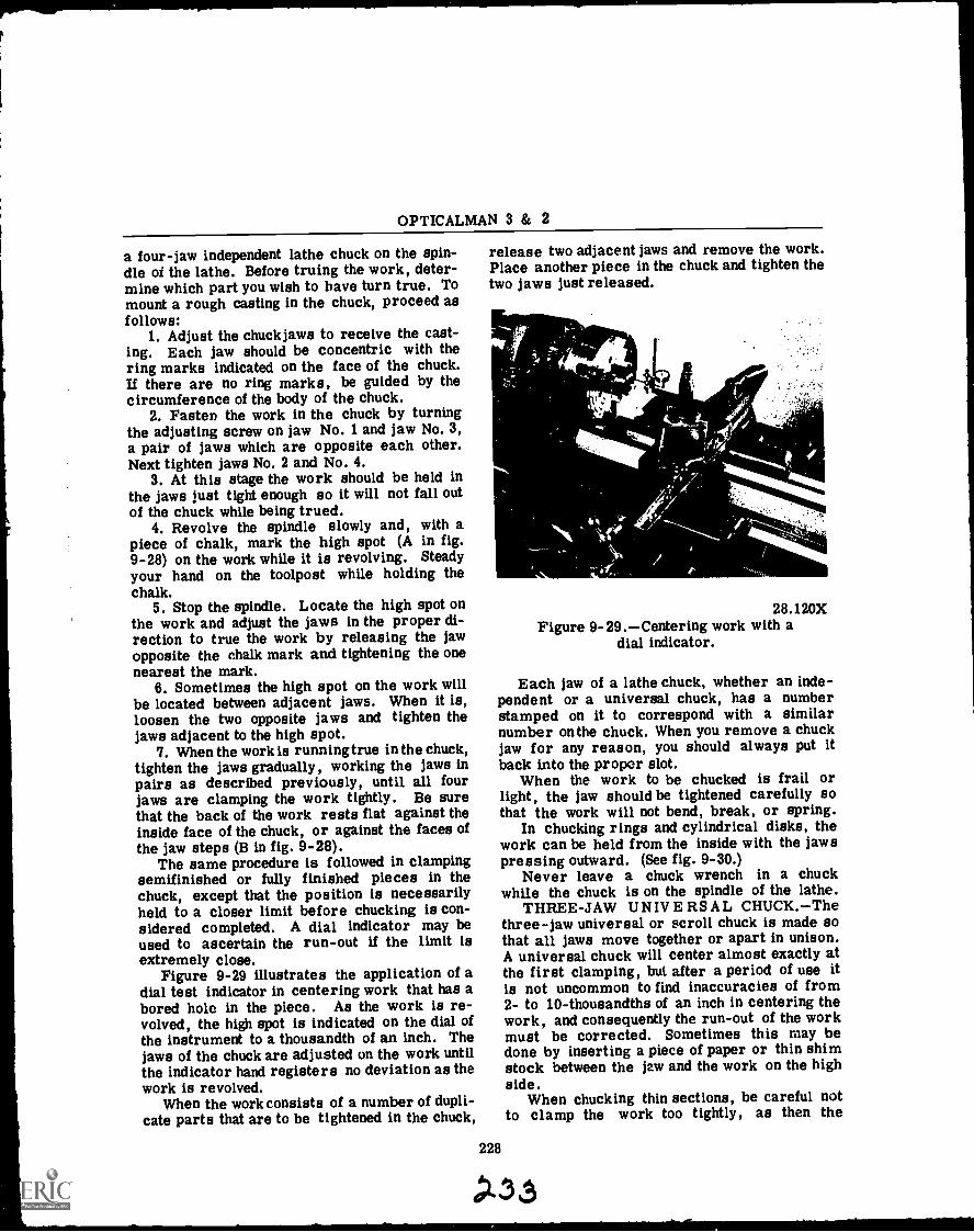
OPTICALMAN 3 & 2
a four-jaw independent lathe chuck on the spin-dle of the lathe. Before truing the work, deter-mine which part you wish to have turn true. Tomount a rough casting in the chuck, proceed asfollows:
1. Adjust the chuck jaws to receive the cast-ing. Each jaw should be concentric with thering marks indicated on the face of the chuck.If there are no ring marks, be guided by thecircumference of the body of the chuck.
2. Fasten the work in the chuck by turningthe adjusting screw on jaw No. 1 and jaw No. 3,a pair of jaws which are opposite each other.Next tighten jaws No. 2 and No. 4.
3. At this stage the work should be held inthe jaws just tight enough so it will not fall outof the chuck while being trued.
4. Revolve the spindle slowly and, with apiece of chalk, mark the high spot (A in fig.9-28) on the work while it is revolving. Steadyyour hand on the toolpost while holding thechalk.
5. Stop the spindle. Locate the high spot onthe work and adjust the jaws in the proper di-rection to true the work by releasing the jawopposite the chalk mark and tightening the onenearest the mark.
6. Sometimes the high spot on the work willbe located between adjacent jaws. When it is,loosen the two opposite jaws and tighten thejaws adjacent to the high spot.
7. When the work is running true in the chuck,tighten the jaws gradually, working the jaws inpairs as described previously, until all fourjaws are clamping the work tightly. Be surethat the back of the work rests flat against theinside face of the chuck, or against the faces ofthe jaw steps (B in fig. 9-28).
The same procedure is followed in clampingsemifinished or fully finished pieces in thechuck, except that the position is necessarilyheld to a closer limit before chucking is con-sidered completed. A dial indicator may beused to ascertain the run-out if the limit isextremely close.
Figure 9-29 illustrates the application of adial test indicator in centering work that has abored hole in the piece. As the work is re-volved, the high spot is indicated on the dial ofthe instrument to a thousandth of an inch. Thejaws of the chuck are adjusted on the work untilthe indicator hand registers no deviation as thework is revolved.
When the work consists of a number of dupli-cate parts that are to be tightened in the chuck,
release two adjacent jaws and remove the work.Place another piece in the chuck and tighten thetwo jaws just released.
228
t'
'141
28.120XFigure 9-29.Centering work with a
dial indicator.
Each jaw of a lathe chuck, whether an inde-pendent or a universal chuck, has a numberstamped on it to correspond with a similarnumber on the chuck. When you remove a chuckjaw for any reason, you should always put itback into the proper slot.
When the work to be chucked is frail orlight, the jaw should be tightened carefully sothat the work will not bend, break, or spring.
In chucking rings and cylindrical disks, thework can be held from the inside with the jawspressing outward. (See fig. 9-30.)
Never leave a chuck wrench in a chuckwhile the chuck is on the spindle of the lathe.
THREE-JAW UNIVERSAL CHUCK.Thethree-jaw universal or scroll chuck is made sothat all jaws move together or apart in unison.A universal chuck will center almost exactly atthe first clamping, but after a period of use itis not uncommon to find inaccuracies of from2- to 10-thousandths of an inch in centering thework, and consequently the run-out of the workmust be corrected. Sometimes this may bedone by inserting a piece of paper or thin shimstock between the jaw and the work on the highside.
When chucking thin sections, be careful notto clamp the work too tightly, as then the
P.33

Chapter 9 MACHINE TOOL OPERATIONPART I
I
28.121Figure 9-30.Work held from inside by a
4-jaw independent chuck.
diameter of the piece will be machined when itis in a distorted position. When the pressure ofthe jaws is released after the cut, there will beas many high spots as there are jaws, and theturned surface will not be true.
Occasionally, you may have to chuck a pieceof work and you do not want the surface to bemarred by the chuck jaws. In this case, acopper or brass shim maybe used between eachchuck jaw and the work.
CARE OF CHUCKS.To preserve a chuck'saccuracy, handle it carefully and keep it cleanand free from grit. Never force a chuck jaw byusing a pipe as an extension on the chuck wrench.
Before mounting a chuck, remove the livecenter and fill the hole with a rag to preventchips and dirt from getting into the taper holeof the spindle.
Clean and oil the threads of the chuck andthe spindle nose. Dirt or chips on the threadswill not allow the chuck to run true when it isscrewed up to the shoulder. Screw the chuckon carefully. Avoid bringing it up against theshoulder so fast that the chuck comes up with ashock. This will strain the spindle and thethreads and make removal difficult. Never usemechanical power in screwing on the chuck.Rotate the spindle with the left hand while hold-ing the chuck in the hollow of the right arm.
To remove a small chuck, place an adjustablejaw wrench on one of the jaws and start it by asmart blow with the hand on the handle of thewrench. To remove a heavy chuck, rotate it
against a block of wood held between a jaw andthe lathe bed. When mounting or removing aheavy chuck, lay a board across the bed ways toprotect them; the board will serve as a supportfor the chuck as it is put on or taken off.
In addition to being supported at the ends bya chuck and center long slender work often re-quires support between ends while being turned;otherwise the work would spring away from thetool and chatter. The center rest is used tosupport such work so it can be accurately turnedwith a faster feed and cutting speed than wouldbe possible without it (see fig. 9-31).
1
229
116..
ist
28.125XFigure 9 -31. Use of a center rest to
support work between centers.
The center rest should be placed where itwill give the greatest support to the piece to beturned. This is usually at about the middle ofits length,
Ensure that the center point between the jawsof the center rest coincides exactly with the axisof the lathe spindle. To do this, place a shortpiece of stock in a chuck and machine it to thediameter of the workpiece to be supported. With-out removing the stock from the chuck, clampthe center rest on the ways of the lathe and ad-just the jaws to the machined surface. Withoutchanging the jaw settings, slide the center restinto position for supporting the workpiece. Re-move the stock used for setting the center restand set the workpiece in place. Use a dial in-dicator to true the workpiece at the chuck. Fig-ure 9-32 shows how a chuckand center rest areused when machining the end of a workpiece.
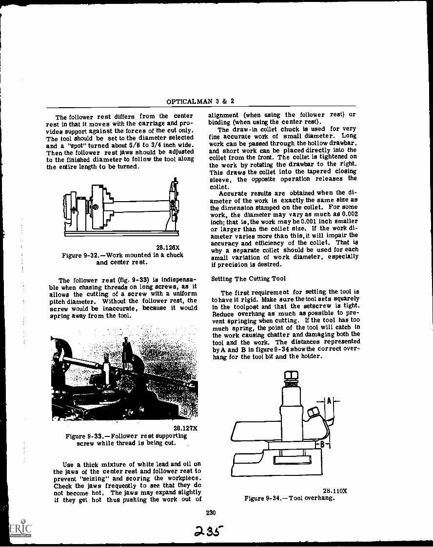
pkb
OPTICALMAN 3 & 2
The follower rest differs from the centerrest in that it moves with the carriage and pro-vides support against the forces of the cut only.The tool should be set to the diameter selectedand a "spot" turned about 5/8 to 3/4 inch wide.Then the follower rest jaws should be adjustedto the finished diameter to follow the tool alongthe entire length to be turned.
28.126XFigure 9-32.Work mounted in a chuck
and center rest.
The follower rest (fig. 9-33) is indispensa-ble when chasing threads on long screws, as itallows the cutting of a screw with a uniformpitch diameter. Without the follower rest, thescrew would be inaccurate, because it wouldspring away from the tool.
28.127XFigure 9-33.Follower rest supporting
screw while thread is being cut.
Use a thick mixture of white lead and oil onthe jaws of the center rest and follower rest toprevent "seizing" and scoring the workpiece.Check the jaws frequently to see that they donot become hot. The jaws may expand slightlyif they get hot thus pushing the work out of
alignment (when using the follower rest) orbinding (when using the center rest).
The draw-in collet chuck is used for veryfine accurate work of small diameter. Longwork can be passed through the hollow drawbar,and short work can be placed directly into thecollet from the front. The collet is tightened onthe work by rotating the drawbar to the right.This draws the collet into the tapered closingsleeve, the opposite operation releases thecollet.
Accurate results are obtained when the di-ameter of the work is exactly the same size asthe dimension stamped on the collet. For somework, the diameter may vary as much as 0.002inch; that is, the work may be 0.001 inch smalleror larger than the collet size. If the work di-ameter varies more than this, it will impair theaccuracy and efficiency of the collet. That iswhy a separate collet should be used for eachsmall variation of work diameter, especiallyif precision is desired.
Setting The Cutting Tool
The first requirement for setting the tool isto have it rigid. Make sure the tool sets squarelyin the toolpost and that the setscrew is tight.Reduce overhang as much as possible to pre-vent springing when cutting. If the tool has toomuch spring, the point of the tool will catch inthe work causing chatter and damaging both thetool and the work. The distances representedby A and B in figure 9-34 show the correct over-hang for the tool bit and the holder.
230
Ss'
28.110XFigure 9 -34. Tool overhang.
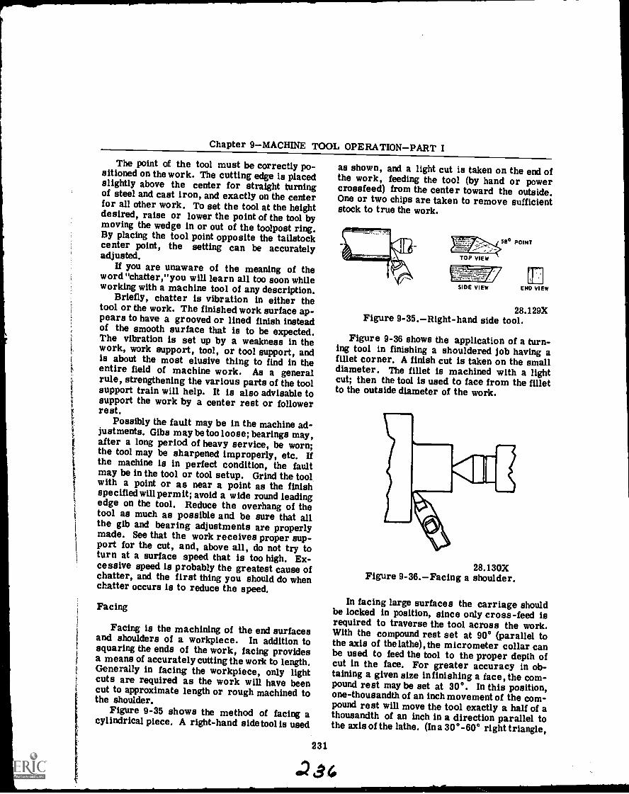
is
Chapter 9MACHINE TOOL OPERATIONPART I
The point of the tool must be correctly po-sitioned on the work. The cutting edge is placedslightly above the center for straight turningof steel and cast iron, and exactly on the centerfor all other work. To set the tool at the heightdesired, raise or lower the point of the tool bymoving the wedge in or out of the toolpost ring.By placing the tool point opposite the tailstockcenter point, the setting can be accuratelyadjusted.
If you are unaware of the meaning of theword "chatter,"you will learn all too soon whileworking with a machine tool of any description.
Briefly, chatter is vibration in either thetool or the work. The finished work surface ap-pears to have a grooved or lined finish insteadof the smooth surface that is to be expected.The vibration is set up by a weakness in thework, work support, tool, or tool support, andis about the most elusive thing to find in theentire field of machine work. As a generalrule, strengthening the various parts of the toolsupport train will help. It is also advisable tosupport the work by a center rest or followerrest.
Possibly the fault may be in the machine ad-justments. Gibs may be too loose; bearings may,after a long period of heavy service, be worn;the tool may be sharpened improperly, etc. Ifthe machine is in perfect condition, the faultmay be in the tool or tool setup. Grind the toolwith a point or as near a point as the finishspecified will permit; avoid a wide round leadingedge on the tool. Reduce the overhang of thetool as much as possible and be sure that allthe gib and bearing adjustments are properlymade. See that the work receives proper sup-port for the cut, and, above all, do not try toturn at a surface speed that is too high. Ex-cessive speed is probably the greatest cause ofchatter, and the first thing you should do whenchatter occurs is to reduce the speed.
Facing
Facing is the machining of the end surfacesand shoulders of a workpiece. In addition tosquaring the ends of the work, facing providesa means of accurately cutting the work to length.Generally in facing the workpiece, only lightcuts are required as the work will have beencut to approximate length or rough machined tothe shoulder.
Figure 9-35 shows the method of facing acylindrical piece. A right-hand side tool is used
as shown, and a light cut is taken on the end ofthe work, feeding the tool (by hand or powercrossfeed) from the center toward the outside.One or two chips are taken to remove sufficientstock to true the work.
231
SIDE VIEW END VIEW
28.129XFigure 9-35.Right-hand side tool.
Figure 9-36 shows the application of a turn-ing tool in finishing a shouldered job having afillet corner. A finish cut is taken on the smalldiameter. The fillet is machined with a lightcut; then the tool is used to face from the filletto the outside diameter of the work.
28.130XFigure 9-36.Facing a shoulder.
In facing large surfaces the carriage shouldbe locked in position, since only cross-feed isrequired to traverse the tool across the work.With the compound rest set at 90° (parallel tothe axis of the lathe), the micrometer collar canbe used to feed the tool to the proper depth ofcut in the face. For greater accuracy in ob-taining a given size in finishing a face, the com-pound rest may be set at 30°. In this position,one-thousandth of an inch movement of the com-pound rest will move the tool exactly a half of athousandth of an inch in a direction parallel tothe axis of the lathe. (Ina 30° -60° right triangle,
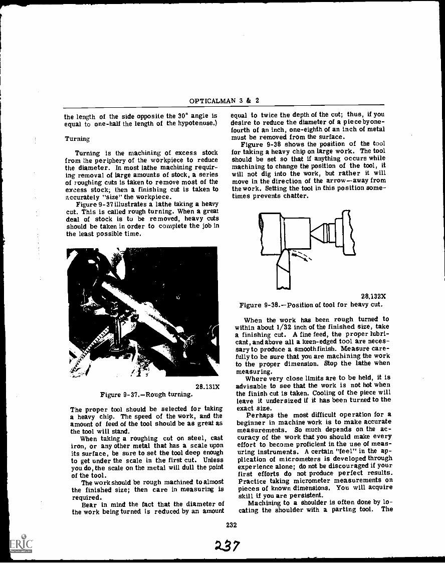
OPTICALMAN 3 & 2
the length of the side opposite the 30° angle isequal to one-half the length of the hypotenuse.)
Turning
Turning is the machining of excess stockfrom the periphery of the workpiece to reducethe diameter. In most lathe machining requir-ing removal of large amounts of stock, a seriesof roughing cuts is taken to remove most of theexcess stock; then a finishing cut is taken toaccurately "size" the workpiece.
Figure 9-37 illustrates a lathe taking a heavycut. This is called rough turning. When a greatdeal of stock is to be removed, heavy cutsshould be taken in order to complete the job inthe least possible time.
14
28.131XFigure 9-37.Rough turning.
The proper tool should be selected for takinga heavy chip. The speed of the work, and theamount of feed of the tool should be as great asthe tool will stand.
When taking a roughing cut on steel, castiron, or any other metal that has a scale uponits surface, be sure to set the tool deep enoughto get under the scale in the first cut. Unlessyou do, the scale on the metal will dull the pointof the tool.
The work should be rough machined to almostthe finished size; then care in measuring isrequired.
Bear in mind the fact that the diameter ofthe work being turned is reduced by an amount
equal to twice the depth of the cut; thus, if youdesire to reduce the diameter of a piece byone-fourth of an inch, one-eighth of an inch of metalmust be removed from the surface.
Figure 9-38 shows the position of the toolfor taking a heavy chip on large work. The toolshould be set so that if anything occurs whilemachining to change the position of the tool, itwill not dig into the work, but rather it willmove in the direction of the arrowaway fromthe work. Setting the tool in this position some-times prevents chatter.
232
28.132XFigure 9-38.Position of tool for heavy cut.
When the work has been rough turned towithin about 1/32 inch of the finished size, takea finishing cut. A fine feed, the proper lubri-cant, and above all a keen-edged tool are neces-sary to produce a smooth finish. Measure care-fully to be sure that you are machining the workto the proper dimension. Stop the lathe whenmeasuring.
Where very close limits are to be held, it isadvisable to see that the work is not hot whenthe finish cut is taken. Cooling of the piece willleave it undersized if it has been turned to theexact size.
Perhaps the most difficult operation for abeginner in machine work is to make accuratemeasurements. So much depends on the ac-curacy of the work that you should make everyeffort to become proficient in the use of meas-uring instruments. A certain "feel" in the ap-plication of micrometers is developed throughexperience alone; do not be discouraged if yourfirst efforts do not produce perfect results.Practice taking micrometer measurements onpieces of known dimensions. You will acquireskill if you are persistent.
Machining to a shoulder is often done by lo-cating the shoulder with a parting tool. The
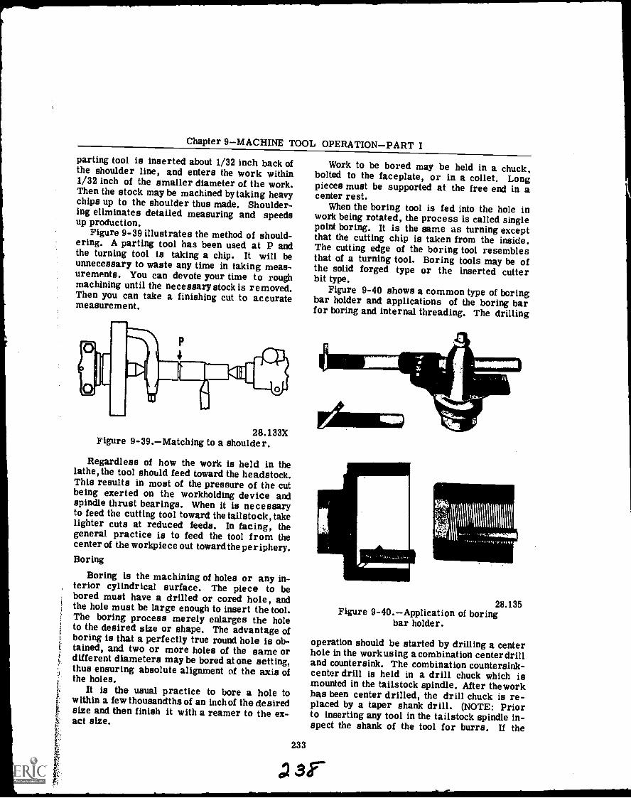
Chapter 9MACHINE TOOL OPERATIONPART Iparting tool is inserted about 1/32 inch back ofthe shoulder line, and enters the work within1/32 inch of the smaller diameter of the work.Then the stock may be machined by taking heavychips up to the shoulder thus made. Shoulder-ing eliminates detailed measuring and speedsup production.
Figure 9-39 illustrates the method of should-ering. A parting tool has been used at P andthe turning tool is taking a chip. It will beunnecessary to waste any time in taking meas-urements. You can devote your time to roughmachining until the necessary stock is removed.Then you can take a finishing cut to accuratemeasurement.
28.133XFigure 9-39.Matching to a shoulder.
Regardless of how the work is held in thelathe, the tool should feed toward the headstock.This results in most of the pressure of the cutbeing exerted on the workholding device andspindle thrust bearings. When it is necessaryto feed the cutting tool toward the tailstock, takelighter cuts at reduced feeds. In facing, thegeneral practice is to feed the tool from thecenter of the workpiece out toward the periphery.Boring
Boring is the machining of holes or any in-terior cylindrical surface. The piece to bebored must have a drilled or cored hole, andthe hole must be large enough to insert the tool.The boring process merely enlarges the holeto the desired size or shape. The advantage ofboring is that a perfectly true round hole is ob-tained, and two or more holes of the same ordifferent diameters maybe bored at one setting,thus ensuring absolute alignment of the axis ofthe holes.
It is the usual practice to bore a hole towithin a few thousandths of an inch of the desiredsize and then finish it with a reamer to the ex-act size.
Work to be bored may be held in a chuck,bolted to the faceplate, or in a collet. Longpieces must be supported at the free end in acenter rest.
When the boring tool is fed into the hole inwork being rotated, the process is called singlepoint boring. It is the same as turning exceptthat the cutting chip is taken from the inside.The cutting edge of the boring tool resemblesthat of a turning tool. Boring tools may be ofthe solid forged type or the inserted cutterbit type.
Figure 9-40 shows a common type of boringbar holder and applications of the boring barfor boring and internal threading. The drilling
233
\V\\11\1\1111
1111111111i
28.135Figure 9-40.Application of boring
bar holder.
operation should be started by drilling a centerhole in the workusing a combination centerdrilland countersink. The combination countersink-center drill is held in a drill chuck which ismounted in the tailstock spindle. After the workhas been center drilled, the drill chuck is re-placed by a taper shank drill. (NOTE: Priorto inserting any tool in the tailstock spindle in-spect the shank of the tool for burrs. If the
23,-
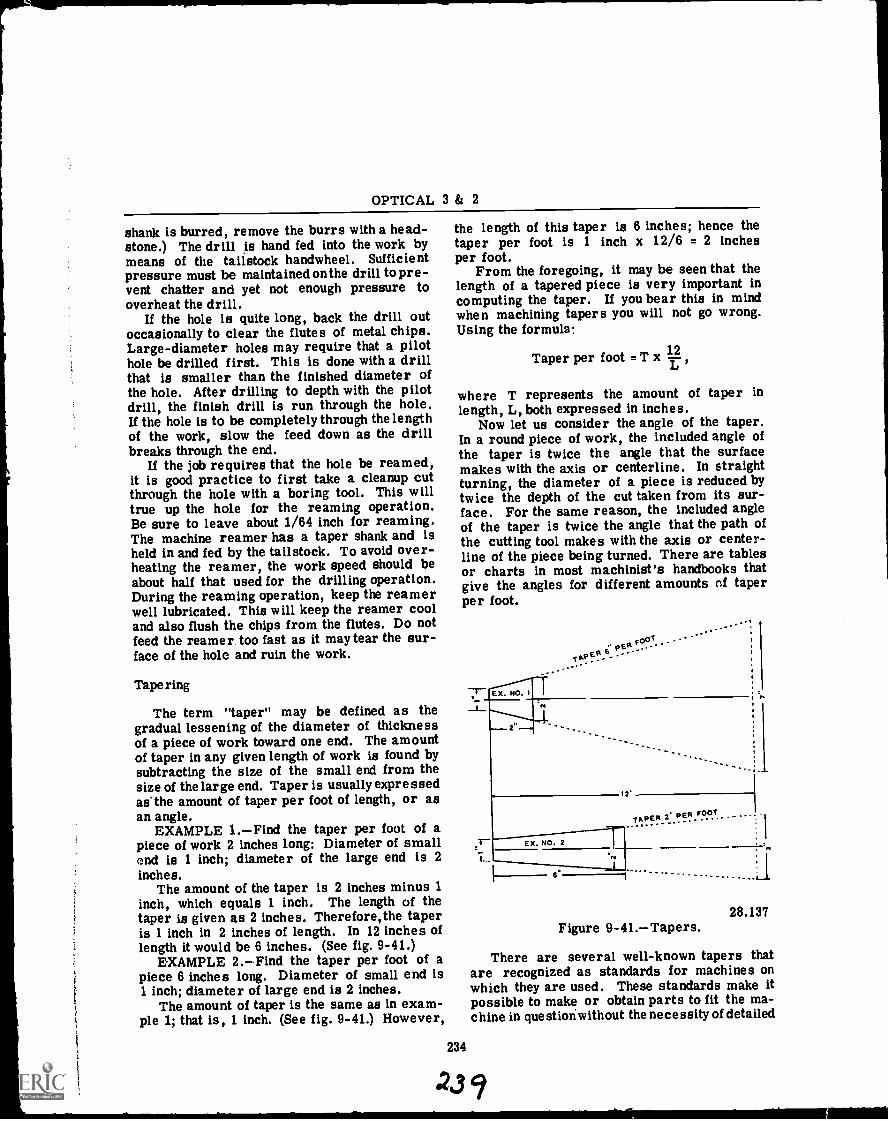
OPTICAL 3 & 2
shank is burred, remove the burrs with a head-stone.) The drill is hand fed into the work bymeans of the tailstock handwheel. Sufficientpressure must be maintained on the drill to pre-vent chatter and yet not enough pressure tooverheat the drill.
If the hole is quite long, back the drill outoccasionally to clear the flutes of metal chips.Large-diameter holes may require that a pilothole be drilled first. This is done with a drillthat is smaller than the finished diameter ofthe hole. After drilling to depth with the pilotdrill, the finish drill is run through the hole.If the hole is to be completely through the lengthof the work, slow the feed down as the drillbreaks through the end.
If the job requires that the hole be reamed,it is good practice to first take a cleanup cutthrough the hole with a boring tool. This willtrue up the hole for the reaming operation.Be sure to leave about 1/64 inch for reaming.The machine reamer has a taper shank and isheld in and fed by the tailstock. To avoid over-heating the reamer, the work speed should beabout half that used for the drilling operation.During the reaming operation, keep the reamerwell lubricated. This will keep the reamer cooland also flush the chips from the flutes. Do notfeed the reamer too fast as it may tear the sur-face of the hole and ruin the work.
Tapering
The term "taper" may be defined as thegradual lessening of the diameter of thicknessof a piece of work toward one end. The amountof taper in any given length of work is found bysubtracting the size of the small end from thesize of the large end. Taper is usually expressedas the amount of taper per foot of length, or asan angle.
EXAMPLE 1.Find the taper per foot of apiece of work 2 inches long: Diameter of smallend is 1 inch; diameter of the large end is 2inches.
The amount of the taper is 2 inches minus 1inch, which equals 1 inch. The length of thetaper is given as 2 inches. Therefore, the taperis 1 inch in 2 inches of length. In 12 inches oflength it would be 6 inches. (See fig. 9-41.)
EXAMPLE 2.Find the taper per foot of apiece 6 inches long. Diameter of small end is1 inch; diameter of large end is 2 inches.
The amount of taper is the same as in exam-ple 1; that is, 1 inch. (See fig. 9-41.) However,
the length of this taper is 6 inches; hence thetaper per foot is 1 inch x 12/6 = 2 inchesper foot.
From the foregoing, it may be seen that thelength of a tapered piece is very important incomputing the taper. If you bear this in mindwhen machining tapers you will not go wrong.Using the formula:
Taper per foot = T x 114,
where T represents the amount of taper inlength, L, both expressed in inches.
Now let us consider the angle of the taper.In a round piece of work, the included angle ofthe taper is twice the angle that the surfacemakes with the axis or centerline. In straightturning, the diameter of a piece is reduced bytwice the depth of the cut taken from its sur-face. For the same reason, the included angleof the taper is twice the angle that the path ofthe cutting tool makes with the axis or center-line of the piece being turned. There are tablesor charts in most machinist's handbooks thatgive the angles for different amounts of taperper foot.
234
23
7- Ex.
e.i; PV
FOet.TAPER
EX. NO. 2
12
. -
T A PEN "" P ER
L_ 1_ - _ - - - _ -
28.137Figure 9-41.Tapers.
There are several well-known tapers thatare recognized as standards for machines onwhich they are used. These standards make itpossible to make or obtain parts to fit the ma-chine in questionwithout the necessity of detailed
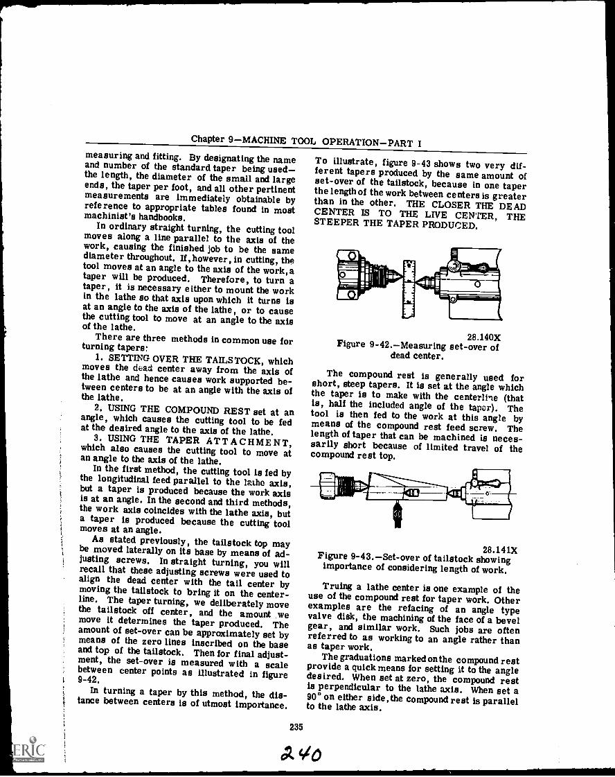
Chapter 9MACHINE TOOL OPERATIONPART Imeasuring and fitting. By designating the nameand number of the standard taper being usedthe length, the diameter of the small and largeends, the taper per foot, and all other pertinentmeasurements are immediately obtainable byreference to appropriate tables found in mostmachinist's handbooks.
In ordinary straight turning, the cutting toolmoves along a line parallel to the axis of thework, causing the finished job to be the samediameter throughout. If,however, in cutting, thetool moves at an angle to the axis of the work,ataper will be produced. Therefore, to turn ataper, it is necessary either to mount the workin the lathe so that axis upon which it turns isat an angle to the axis of the lathe, or to causethe cutting tool to move at an angle to the axisof the lathe.
There are three methods in common use forturning tapers:
1. SETTING OVER THE TAILSTOCK, whichmoves the dead center away from the axis ofthe lathe and hence causes work supported be-tween centers to be at an angle with the axis ofthe lathe.
2. USING THE COMPOUND REST set at anangle, which causes the cutting tool to be fedat the desired angle to the axis of the lathe.
3. USING THE TAPER ATTACHMENT,which also causes the cutting tool to move atan angle to the axis of the lathe.
In the first method, the cutting tool is fed bythe longitudinal feed parallel to the lathe axis,but a taper is produced because the work axisis at an angle. In the second and third methods,the work axis coincides with the lathe axis, buta taper is produced because the cutting toolmoves at an angle.
As stated previously, the tailstock top maybe moved laterally on its base by means of ad-justing screws. In straight turning, you willrecall that these adjusting screws were used toalign the dead center with the tail center bymoving the tailstock to bring it on the center-line. The taper turning, we deliberately movethe tailstock off center, and the amount wemove it determines the taper produced. Theamount of set-over can be approximately set bymeans of the zero lines inscribed on the baseand top of the tailstock. Then for final adjust-ment, the set-over is measured with a scalebetween center points as illustrated in figure9-42.
In turning a taper by this method, the dis-tance between centers is of utmost importance.
To illustrate, figure 9-43 shows two very dif-ferent tapers produced by the same amount ofset-over of the tailstock, because in one taperthe length of the work between centers is greaterthan in the other. THE CLOSER THE DEADCENTER IS TO THE LIVE CENTER, THESTEEPER THE TAPER PRODUCED.
28.140XFigure 9-42.Measuring set-over of
dead center.
The compound rest is generally used forshort, steep tapers. It is set at the angle whichthe taper is to make with the centerline (thatis, half the included angle of the taper). Thetool is then fed to the work at this angle bymeans of the compound rest feed screw. Thelength of taper that can be machined is neces-sarily short because of limited travel of thecompound rest top.
235
EINVI :I gib41,11
28.141XFigure 9-43.Set-over of tailstock showing
importance of considering length of work.
Truing a lathe center is one example of theuse of the compound rest for taper work. Otherexamples are the refacing of an angle typevalve disk, the machining of the face of a bevelgear, and similar work. Such jobs are oftenreferred to as working to an angle rather thanas taper work.
The graduations markedon the compound restprovide a quick means for setting it to the angledesired. When set at zero, the compound restis perpendicular to the lathe axis. When set a90° on either side, the compound rest is parallelto the lathe axis.
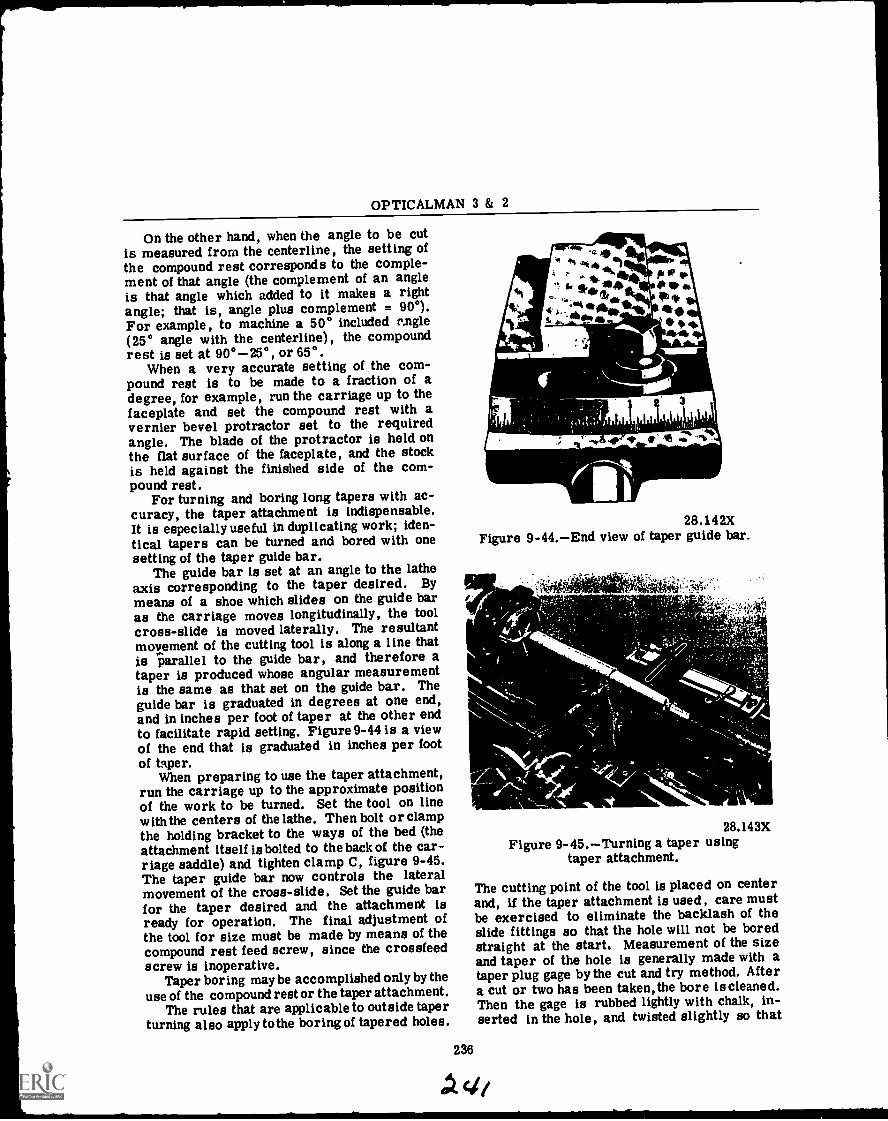
OPTICALMAN 3 & 2
On the other hand, when the angle to be cutis measured from the centerline, the setting ofthe compound rest corresponds to the comple-ment of that angle (the complement of an angleis that angle which added to it makes a rightangle; that is, angle plus complement = 900).For example, to machine a 50° included r.ngle(25° angle with the centerline), the compoundrest is set at 900-25°, or 65°.
When a very accurate setting of the com-pound rest is to be made to a fraction of adegree, for example, run the carriage up to thefaceplate and set the compound rest with avernier bevel protractor set to the requiredangle. The blade of the protractor is held onthe flat surface of the faceplate, and the stockis held against the finished side of the com-pound rest.
For turning and boring long tapers with ac-curacy, the taper attachment is indispensable.It is especially useful in duplicating work; iden-tical tapers can be turned and bored with onesetting of the taper guide bar.
The guide bar is set at an angle to the latheaxis corresponding to the taper desired. Bymeans of a shoe which slides on the guide baras the carriage moves longitudinally, the toolcross-slide is moved laterally. The resultantmovement of the cutting tool is along a line thatis parallel to the guide bar, and therefore ataper is produced whose angular measurementis the same as that set on the guide bar. Theguide bar is graduated in degrees at one end,and in inches per foot of taper at the other endto facilitate rapid setting. Figure9-44 is a viewof the end that is graduated in inches per foot
of taper.When preparing to use the taper attachment,
run the carriage up to the approximate positionof the work to be turned. Set the tool on linewith the centers of the lathe. Then bolt or clampthe holding bracket to the ways of the bed (theattachment itself is bolted to the back of the car-riage saddle) and tighten clamp C, figure 9-45.The taper guide bar now controls the lateralmovement of the cross-slide. Set the guide barfor the taper desired and the attachment isready for operation. The final adjustment ofthe tool for size must be made by means of thecompound rest feed screw, since the crossfeedscrew is inoperative.
Taper boring may be accomplished only by theuse of the compound rest or the taper attachment.
The rules that are applicable to outside taperturning also apply tothe boring of tapered holes.
28.142XFigure 9-44.End view of taper guide bar.
236
28.143XFigure 9-45.Turning a taper using
taper attachment.
The cutting point of the tool is placed on centerand, if the taper attachment is used, care mustbe exercised to eliminate the backlash of theslide fittings so that the hole will not be boredstraight at the start. Measurement of the sizeand taper of the hole is generally made with ataper plug gage by the cut and try method. Aftera cut or two has been taken,the bore is cleaned.Then the gage is rubbed lightly with chalk, in-serted in the hole, and twisted slightly so that

Chapter 9MACHINE TOOL OPERATIONPART I
the chalk will show where the gate is bearing.Any necessary corrections may then be madeand the boring continued until the taper isbrought to size. Avery light application of prus-sian blue to the gage will give better resultsthan chalk for accurate work.
When making a blind tapered hole, such asmay be required in drill sockets, it is best todrill the hole carefully to the correct depth witha drill of the same size as specified for thesmall end of the hole. This gives the advantageof boring to the right size without the removalof metal at the extreme bottom of the bore,which is rather difficult, particularly in small,deep holes.
For turning and boring tapers, the tool cuttingedge should be set exactly at the center of thework.. That is, set the point of the cutting edgeeven with the height of the lathe centers.
In testing the taper on a piece of work thatis to fit a spindle and is nearly finished, makea chalk mark along the side of the test piece.Place the test piece in the taper hole and turnthe piece carefully by hand. Then remove thetest piece and the chalk mark will show wherethe taper is bearing. If the taper is a perfectfit, the entire length of the chalk mark willsmear. If the fit is not perfect, the chalk markwill show where the adjustment is needed. Makethe adjustment, take another light cut and testagain. Be sure the taper is correct before turn-ing to the finished diameter.
E=21111028.144X
Figure 9-46.Morse taper socket gageand plug gage.
Figure 9-46 shows a Morse standard taperplug and a taper socket gage. They not only givethe proper taper, but also show the proper dis-tance that the taper should enter the spindle.
Threading
Most of the machine work done by an optical-man will include V-form threads even thoughnormal duties will bring you in contact with
28.147XFigure 9-47.Acme thread.
acme threads, and square threads (figs. 9-47and 9-48).
Each of these thread forms is used for spe-cific applications. V-form threads are com-monly used on fastening devices such as boltsand nuts as well as on machine parts. Acmescrew threads are generally used for transmit-ting motion such as that between the lead screwand lathe carriage. Square threads are used toincrease mechanical advantage and to providegood clamping ability as in the screw jack orvise screw.
28.149XFigure 9-48.Square thread.
There are several terms used in describingscrew threads and screw thread systems whichyou must know before you can calculate andmachine screw threads. Figure 9-49 illustratesthe application of some of the following terms:
External thread.A thread on the externalsurface of a cylinder.
Internal thread.A thread on the internalsurface of a hollow cylinder.
Right-hand thread.A thread which, whenviewed axially, winds in a clockwise and reced-ing direction.
Left-hand thread.A thread which, whenviewed axially, winds in a counterclockwise andreceding direction.
237
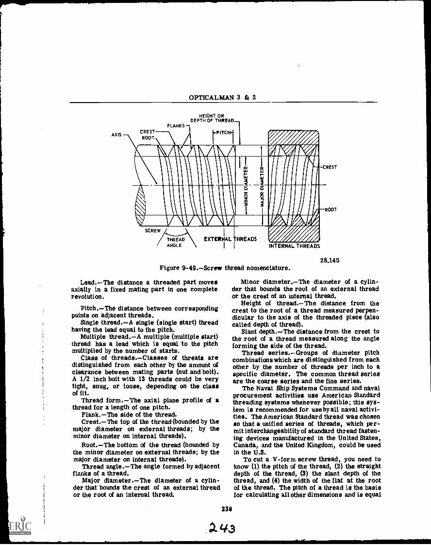
OPTICALMAN 3 & 2
AXISCREST
ROOT
FLANKS
HEIGHT ORDEPTH OF THREAD
PITCH{
Ali KIL AL
nou 111141
taw---..\\THREAD EXTERNAL HREADS
IANGLE INTERNAL THREADS
Figure 9-49.Screw thread nomenclature.
Lead.The distance a threaded part movesaxially in a fixed mating part in one completerevolution.
Pitch.The distance between correspondingpoints on adjacent threads.
Single thread.A single (single start) threadhaving the lead equal to the pitch.
Multiple thread.A multiple (multiple start)thread has a lead which is equal to the pitchmultiplied by the number of starts.
Class of threads.Classes of threats aredistinguished from each other by the amount ofclearance between mating parts (nut and bolt).A 1/2 inch bolt with 13 threads could be verytight, snug, or loose, depending on the classof fit.
Thread form.The axial plane profile of athread for a length of one pitch.
Flank.The side of the thread.Crest.The top of the thread (bounded by the
major diameter on external threads; by theminor diameter on internal threads).
Root.The bottom of the thread (bounded bythe minor diameter on external threads; by themajor diameter on internal threads).
Thread angle.The angle formed by adjacentflanks of a thread.
Major diameter.The diameter of a cylin-der that bounds the crest of an external threador the root of an internal thread.
CREST
ROOT
28.145
Minor diameter.The diameter of a cylin-der that bounds the root of an external threador the crest of an internal thread.
Height of thread.The distance from thecrest to the root of a thread measured perpen-dicular to the axis of the threaded piece (alsocalled depth of thread).
Slant depth.The distance from the crest tothe root of a thread measured along the angleforming the side of the thread.
Thread series.Groups of diameter pitchcombinationswhich are distinguished from eachother by the number of threads per inch to aspecific diameter. The common thread seriesare the coarse aeries and the fine series.
The Naval Ship Systems Command and navalprocurement activities use American Standardthreading systems whenever possible; this sys-tem is recommended for use by all naval activi-ties. The American Standard thread was chosenso that a unified series of threads, which per-mit interchangeability of standard thread fasten-ing devices manufactured in the United States,Canada, and the United Kingdom, could be usedin the U.S.
To cut a V-form screw thread, you need toknow (1) the pitch of the thread, (2) the straightdepth of the thread, (3) the slant depth of thethread, and (4) the width of the flat at the rootof the thread. The pitch of a thread is the basisfor calculating all other dimensions and is equal
238
43
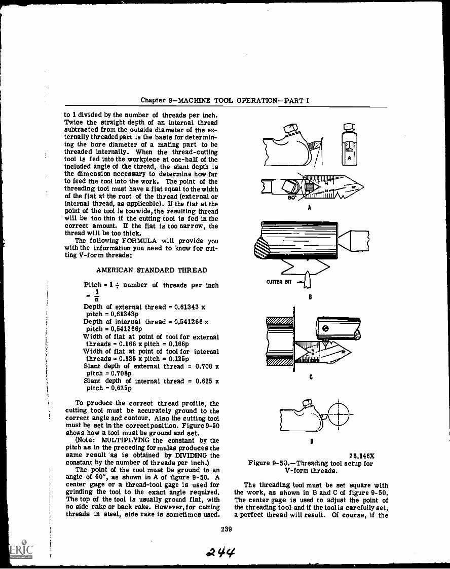
Chapter 9MACHINE TOOL OPERATIONPART I
to 1 divided by the number of threads per inch.Twice the straight depth of an internal threadsubtracted from the outside diameter of the ex-ternally threaded part is the basis for determin-ing the bore diameter of a mating part to bethreaded internally. When the thread-cuttingtool is fed into the workpiece at one-half of theincluded angle of the thread, the slant depth isthe dimension necessary to determine how farto feed the tool into the work. The point of thethreading tool must have a flat equal to thewidthof the flat at the root of the thread (external orinternal thread, as applicable). If the flat at thepoint of the tool is toowide, the resulting threadwill be too thin if the cutting tool is fed in thecorrect amount. If the flat is too narrow, thethread will be too thick.
The following FORMULA will provide youwith the information you need to know for cut-ting V-f or m threads:
AMERICAN STANDARD THREAD
Pitch = 1 = number of threads per inch1
nDepth of external thread = 0.61343 xpitch = 0.61343p
Depth of internal thread = 0.541266 xpitch = 0.541266p
Width of flat at point of tool for externalthreads = 0.166 x pitch = 0.166p
Width of flat at point of tool for internalthreads = 0.125 x pitch = 0.125pSlant depth of external thread = 0.708 xpitch = 0.708pSlant depth of internal thread = 0.625 xpitch = 0.625p
To produce the correct thread profile, thecutting tool must be accurately ground to thecorrect angle and contour. Also the cutting toolmust be set in the correct position. Figure 9-50shows how a tool must be ground and set.
(Note: MULTIPLYING the constant by thepitch as in the preceding formulas produces thesame result as is obtained by DIVIDING theconstant by the number of threads per inch.)
The point of the tool must be ground to anangle of 60°, as shown in A of figure 9-50. Acenter gage or a thread-tool gage is used forgrinding the tool to the exact angle required.The top of the tool is usually ground flat, withno side rake or back rake. However, for cuttingthreads in steel, side rake is sometimes used.
239
A
CUTTER BIT
B
C
D
28.146XFigure 9-53.Threading tool setup for
V-form threads.
The threading tool must be set square withthe work, as shown in B and C of figure 9-50.The center gage is used to adjust the point ofthe threading tool and if the tool is carefully set,a perfect thread will result. Of course, if the
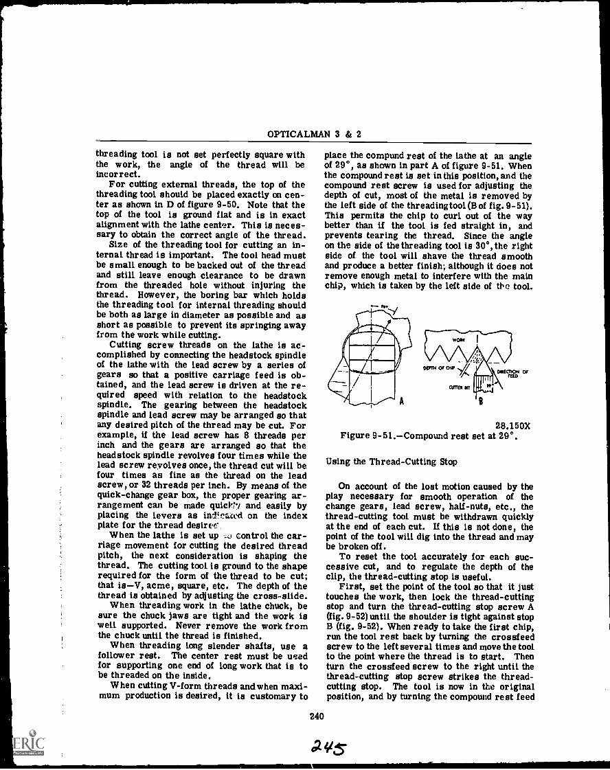
OPTICALMAN 3 & 2
threading tool is not set perfectly square withthe work, the angle of the thread will beincorrect.
For cutting external threads, the top of thethreading tool should be placed exactly on cen-ter as shown in D of figure 9-50. Note that thetop of the tool is ground flat and is in exactalignment with the lathe center. This is neces-sary to obtain the correct angle of the thread.
Size of the threading tool for cutting an in-ternal thread is important. The tool head mustbe small enough to be backed out of the threadand still leave enough clearance to be drawnfrom the threaded hole without injuring thethread. However, the boring bar which holdsthe threading tool for internal threading shouldbe both as large in diameter as possible and asshort as possible to prevent its springing awayfrom the work while cutting.
Cutting screw threads on the lathe is ac-complished by connecting the headstock spindleof the lathe with the lead screw by a series ofgears so that a positive carriage feed is ob-tained, and the lead screw is driven at the re-quired speed with relation to the headstockspindle. The gearing between the headstockspindle and lead screw may be arranged so thatany desired pitch of the thread may be cut. Forexample, if the lead screw has 8 threads perinch and the gears are arranged so that theheadstock spindle revolves four times while thelead screw revolves once, the thread cut will befour times as fine as the thread on the leadscrew, or 32 threads per inch. By means of thequick-change gear box, the proper gearing ar-rangement can be made quicY17 and easily byplacing the levers as ind!fmced on the indexplate for the thread desire!'
When the lathe is set up control the car-riage movement for cutting the desired threadpitch, the next consideration is shaping thethread. The cutting tool is ground to the shaperequired for the form of the thread to be cut;that isV, acme, square, etc. The depth of thethread is obtained by adjusting the cross-slide.
When threading work in the lathe chuck, besure the chuck jaws are tight and the work iswell supported. Never remove the work fromthe chuck until the thread is finished.
When threading long slender shafts, use afollower rest. The center rest must be usedfor supporting one end of long work that is tobe threaded on the inside.
When cutting V-form threads and when maxi-mum production is desired, it is customary to
place the compund rest of the lathe at an angleof 29°, as shown in part A of figure 9-51. Whenthe compound rest is set in this position, and thecompound rest screw is used for adjusting thedepth of cut, most of the metal is removed bythe left side of the threading tool (B of fig. 9-51).This permits the chip to curl out of the waybetter than if the tool is fed straight in, andprevents tearing the thread. Since the angleon the side of the threading tool is 30°, the rightside of the tool will shave the thread smoothand produce a better finish; although it does notremove enough metal to interfere with the mainchip, which is taken by the left side of the tool.
28,150XFigure 9-51.Compound rest set at 29°.
Using the Thread-Cutting Stop
On account of the lost motion caused by theplay necessary for smooth operation of thechange gears, lead screw, half-nuts, etc., thethread-cutting tool must be withdrawn quicklyat the end of each cut. If this is not done, thepoint of the tool will dig into the thread and maybe broken off.
To reset the tool accurately for each suc-cessive cut, and to regulate the depth of theclip, the thread-cutting stop is useful.
First, set the point of the tool so that it justtouches the work, then lock the thread-cuttingstop and turn the thread-cutting stop screw A(fig. 9-52) until the shoulder is tight against stopB (fig. 9-52). When ready to take the first chip,run the tool rest back by turning the crossfeedscrew to the left several times and move the toolto the point where the thread is to start. Thenturn the crossfeed screw to the right until thethread-cutting stop screw strikes the thread-cutting stop. The tool is now in the originalposition, and by turning the compound rest feed
240
a vs-
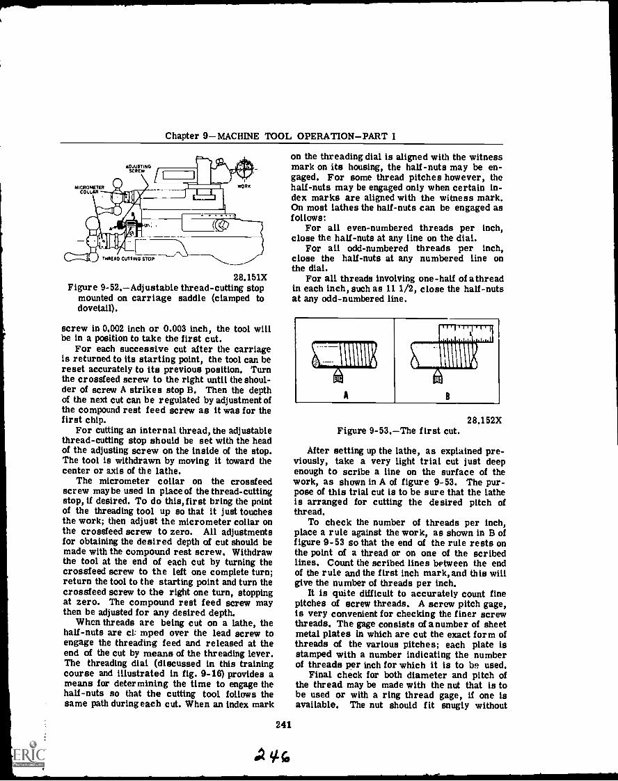
Chapter 9MACHINE TOOL OPERATIONPART I
MICROMETERCOLLAR
ADJUSTINGSCREW
WORK
THREAD CUTTING STOP
28.151XFigure 9-52.Adjustable thread-cutting stop
mounted on carriage saddle (clamped todovetail).
screw in 0.002 inch or 0.003 inch, the tool willbe in a position to take the first cut.
For each successive cut after the carriageis returned to its starting point, the tool can bereset accurately to its previous position. Turnthe crossfeed screw to the right until the shoul-der of screw A strikes stop B. Then the depthof the next cut can be regulated by adjustment ofthe compound rest feed screw as it was for thefirst chip.
For cutting an internal thread, the adjustablethread-cutting stop should be set with the headof the adjusting screw on the inside of the stop.The tool is withdrawn by moving it toward thecenter or axis of the lathe.
The micrometer collar on the crossfeedscrew maybe used in place of the thread-cuttingstop, if desired. To do this, first bring the pointof the threading tool up so that it just touchesthe work; then adjust the micrometer collar onthe crossfeed screw to zero. All adjustmentsfor obtaining the desired depth of cut should bemade with the compound rest screw. Withdrawthe tool at the end of each cut by turning thecrossfeed screw to the left one complete turn;return the tool to the starting point and turn thecrossfeed screw to the right one turn, stoppingat zero. The compound rest feed screw maythen be adjusted for any desired depth.
When threads are being cut on a lathe, thehalf-nuts are ci: mped over the lead screw toengage the threading feed and released at theend of the cut by means of the threading lever.The threading dial (discussed in this trainingcourse and illustrated in fig. 9-16) provides ameans for determining the time to engage thehalf-nuts so that the cutting tool follows thesame path during each cut. When an index mark
on the threading dial is aligned with the witnessmark on its housing, the half-nuts may be en-gaged. For some thread pitches however, thehalf-nuts may be engaged only when certain in-dex marks are aligned with the witness mark.On most lathes the half-nuts can be engaged asfollows:
For all even-numbered threads per inch,close the half-nuts at any line on the dial.
For all odd-numbered threads per inch,close the half-nuts at any numbered line onthe dial.
For all threads involving one-half of a threadin each inch, such as 11 1/2, close the half-nutsat any odd-numbered line.
241
oc.
28.152XFigure 9-53.The first cut.
After setting up the lathe, as explained pre-viously, take a very light trial cut just deepenough to scribe a line on the surface of thework, as shown in A of figure 9-53. The pur-pose of this trial cut is to be sure that the latheis arranged for cutting the desired pitch ofthread.
To check the number of threads per inch,place a rule against the work, as shown in B offigure 9-53 so that the end of the rule rests onthe point of a thread or on one of the scribedlines. Count the scribed lines between the endof the rule and the first inch mark, and this willgive the number of threads per inch.
It is quite difficult to accurately count finepitches of screw threads. A screw pitch gage,is very convenient for checking the finer screwthreads. The gage consists of a number of sheetmetal plates in which are cut the exact form ofthreads of the various pitches; each plate isstamped with a number indicating the numberof threads per inch for which it is to be used.
Final check for both diameter and pitch ofthe thread may be made with the nut that is tobe used or with a ring thread gage, if one isavailable. The nut should fit snugly without
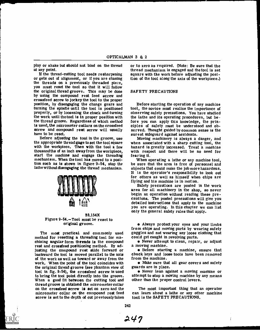
OPTICALMAN 3 & 2
play or shake but should not bind on the threadat any point.
If the thread-cutting tool needs resharpeningor gets out of alignment, or if you are chasingthe threads on a previously threaded piece,you must reset the tool so that it will followthe original thread groove. This may be doneby using the compound rest feed screw andcrossfeed screw to jockey the tool to the properposition, by disengaging the change gears andturning the spindle until the tool is positionedproperly, or by loosening the chuck and turningthe work until the tool is In proper position withthe thread groove. Regardless of which methodis used, the micrometer collars on the crossfeedscrew and compound rest screw will usuallyhave to be reset.
Before adjusting the tool in the groove, usethe appropriate thread gage to set the tool squarewith the workpiece. Then with the tool a fewthousandths of an inch away from the workpiece,start the machine and engage the threadingmechanism. When the tool has moved to a posi-tion such as is shown in figure 9-54, stop thelathe without disengaging the thread mechanism.
28.154XFigure 9-54.Tool must be reset to
original groove.
The most practical and commonly usedmethod for resetting a threading tool for ma-chining angular form threads is the compoundrest and crossfeed positioning method. By ad-justing the compound rest slide forward orbackward the tool is moved parallel to the axisof the work as well as toward or away from thework. When the point of the tool coincides withthe original thread groove (see phantom view oftool in fig. 9-54), the crossfeed screw is usedto bring the tool point directly into the groove.When a good fit between the cutting tool andthread groove is obtained the micrometer collaron the crossfeed screw is set on zero and themicrometer collar on the compound rest feedscrew is set to the depth of cut previously taken
or to zero as required. (Note: Be sure that thethread mechanism is engaged and the tool is setsquare with the work before adjusting the posi-tion of the tool along the axis of the workpiece.)
SAFETY PRECAUTIONS
Before starting the operation of any machinetool, the novice must realize the importance ofobserving safety precautions. You have studiedthe lathe and its operating procedures, but be-fore you can apply this knowledge, the prin-ciples of safety must be understood and ob-served. Thought guided by common sense is thesurest safeguard against accidents.
Moving machinery is always a danger, andwhen associated with a sharp cutting tool, thehazard is greatly increased. Treat a machinewith respect and there will be no need forfearing it.
When operating a lathe or any machine tool,be sure that the area is free of personnel andobjects that could make the job more hazardous.It is the operator's responsibility to look outfor others as well as himself when chips areflying and his machine is in motion.
Safety precautions are posted in the workarea for all machinery in the shop, so neverbegin an operation without reading these pre-cautions. The posted precautions will give youdetailed instructions that apply to the machineyou are operating. In this chapter we can listonly the general safety rules that apply.
Always protect your eyes and your limbsfrom chips and moving parts by wearing safetygoggles and not wearing any loose clothing thatcould get caught in revolving parts.
Never attempt to clean, repair, or adjusta moving machine.
Before starting a machine, ensure thatchuck keys and loose tools have been removedfrom the machine.
Make sure that all gear covers and safetyguards are in place.
Never lean against a moving machine orattempt to stop a moving machine by any meansother than the proper control levers.
The most important thing that an operatorcan learn about a lathe or any other machinetool is the SAFETY PRECAUTIONS.
242
CHAPTER 10
MACHINE TOOL OPERATION-PART II
GRINDERS
Grinding is the removal of metal by the cuttingaction of an abrasive. Offhand grinding is a termused to describe the manual holding and manip-ulation of a workpiece when grinding. To grindaccurately and safely, using the offhand method,you must have experience and practice. In ad-dition, you must know how to select and installgrinding wheels, how to sharpen or dress them,and you must have a knowledge of the safety pre-cautions concerning grinding.
To properly grind small handtools, single-edged cutting tools, and twist drills, you musthave a knowledge of the terms used to describethe angles and surfaces of the tools, you mustknow for what operations each tool is used, andyou must know the composition of the toolmaterial.
Bench and pedestal grinders are relativelysimple machines. The maincomponents of thesegrinders are: a motor with an extended shaftfor mounting of grinding wheels, a mountingbase for the motor, grinding wheel guards whichare mounted over the grinding wheel as a safetyfeature, a provision for coolants, an adjustabletoolrest for steadying the workpiece, and ashield which is fastened to the wheel guards toprotect the operator from flying chips. Figure10-1 shows a representative bench grinder.
Bench grinders are mounted on workbenches.They are used for grinding and sharpening ofsmall tools. These grinders do not have installedcoolant systems; however, a container for thecoolant is usually mounted or placed near thegrinder. Grinding wheels up to 8 inches in di-ameter and 1 inch in thickness are normallyused on bench grinders.
Pedestal grinders are usually heavy dutybench grinders which set on a pedestal fastenedto the deck. They normally have a coolant sys-tem which includes a pump, storage pump, and ahose and fittings to carry the coolant to thewheel surface. Pedestal grinders are particu-larly useful for rough grinding such as "snag-ging" castings. Figure 10-2 shows a pedestalgrinder in use.
When operating a bench or pedestal grinder,observe all safety precautions for the machine.Ensure that all safety guards and shields aresecured in the proper position.
GRINDING SAFETY
The grinding wheel is a fragile cutting toolwhich operates at high speeds. Great emphasismust be given, therefore, to the safe operationof bench and pedestal grinders. Observance ofsafety precautions, posted on or near all grindersused in the Navy, is mandatory for the safetyof the operator and the safety of personnel inthe nearby vincinity.
What are the most common sources of injuryduring grinding operation? Hazards leading toeye injury caused by grit generated by the grind-ing process are the most common and the mostserious. Abrasions caused by bodily contactwith the wheel are quite painful and can be seri-ous. Cuts and bruises caused by segments ofan exploded wheel, or a tool "kicked" awayfrom the wheel are other sources of injury.Cuts and abrasions can become infected if notprotected from grit and dust from grinding.
Safety in using bench and pedestal grindersis primarily a matter of using common sense andconcentrating on the job at hand. Each time youstart to grind a tool, stop briefly to considerhow observance of safety precautions and theuse of safeguards protect you from injury. Con-sider the complications that could be caused byyour loss of sight, or loss or mutilation of anarm or hand.
Some guidelines for safe grinding practicesare:
1. Read posted safety precautions beforestarting to use a machine. In addition to re-freshing your memory about safe grinding prac-tices, this gets your mind on the job at hand.
2. Secure all loose clothing and remove ringsor other jewelry.
3. Inspect the grinding wheel, wheel guards,the toolrest, and other safety devices to ensurethey are in good condition and positioned prop-erly. Set the toolrest so that it is within 1/8
243
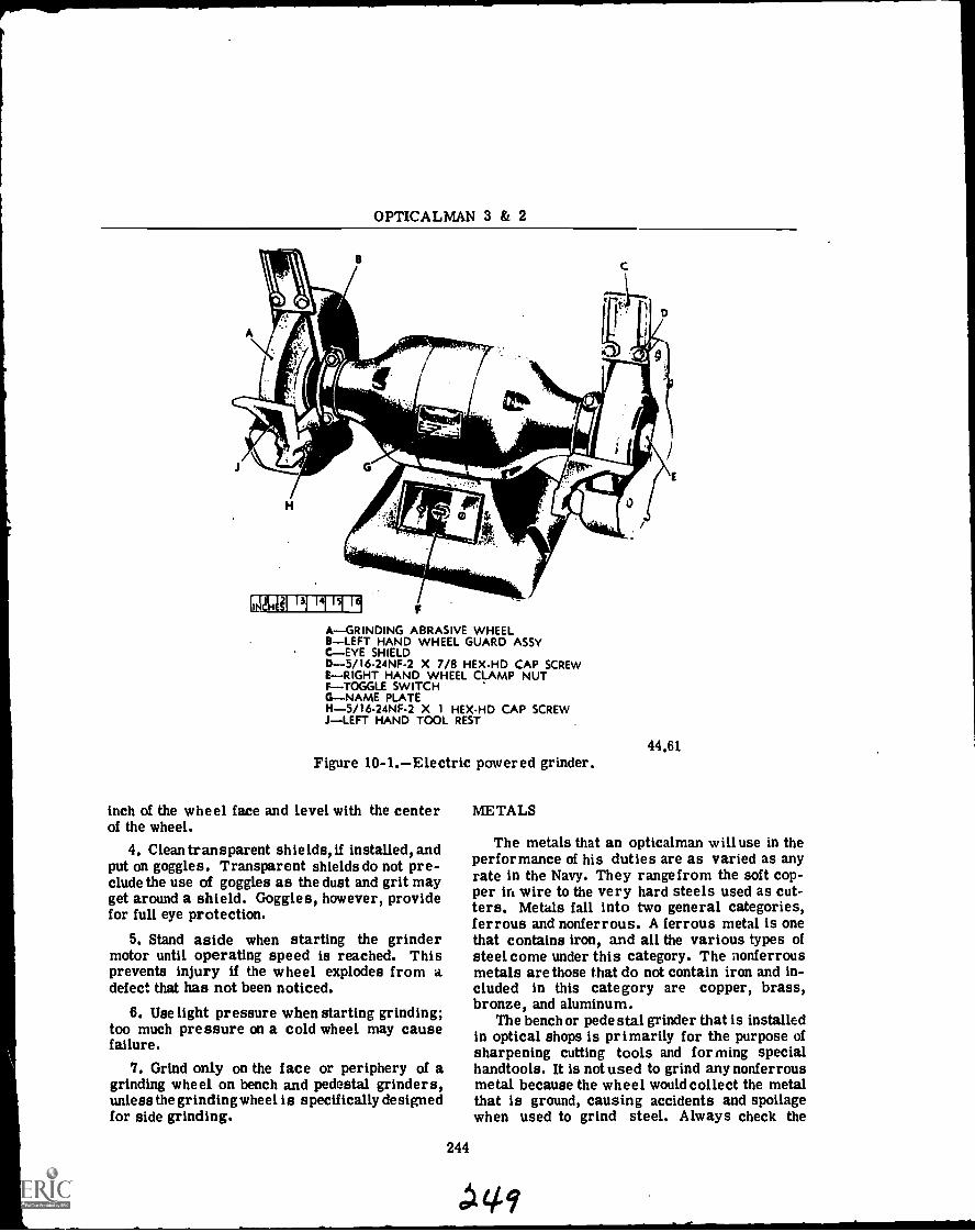
OPTICALMAN 3 & 2
F
A-GRINDING ABRASIVE WHEEL8 -LEFT HAND WHEEL GUARD ASSYC-EYE SHIELDD-5/16-24NF-2 X 7/8 HEX-HD CAP SCREWE-RIGHT HAND WHEEL CLAMP NUTF-TOGGLE SWITCHG-NAME PLATEH-5/16-24NF-2 X 1 HEX-HD CAP SCREWJ-LEFT HAND TOOL REST
44.61Figure 10 -1. Electric powered grinder.
inch of the wheel face and level with the centerof the wheel.
4. Clean transparent shields, if installed, andput on goggles. Transparent shields do not pre-clude the use of goggles as the dust and grit mayget around a shield. Goggles, however, providefor full eye protection.
5. Stand aside when starting the grindermotor until operating speed is reached. Thisprevents injury if the wheel explodes from adefect that has not been noticed.
6. Use light pressure when starting grinding;too much pressure on a cold wheel may causefailure.
7. Grind only on the face or periphery of agrinding wheel on bench and pedestal grinders,unless the grinding wheel is specifically designedfor side grinding.
244
METALS
The metals that an opticalman will use in theperformance of his duties are as varied as anyrate in the Navy. They rangefrom the soft cop-per in wire to the very hard steels used as cut-ters. Metals fall into two general categories,ferrous and nonferrous. A ferrous metal is onethat contains iron, and all the various types ofsteel come under this category. The nonferrousmetals are those that do not contain iron and in-cluded in this category are copper, brass,bronze, and aluminum.
The bench or pede stal grinder that is installedin optical shops is primarily for the purpose ofsharpening cutting tools and forming specialhandtools. It is not used to grind any nonferrousmetal because the wheel would collect the metalthat is ground, causing accidents and spoilagewhen used to grind steel. Always check the
IP?
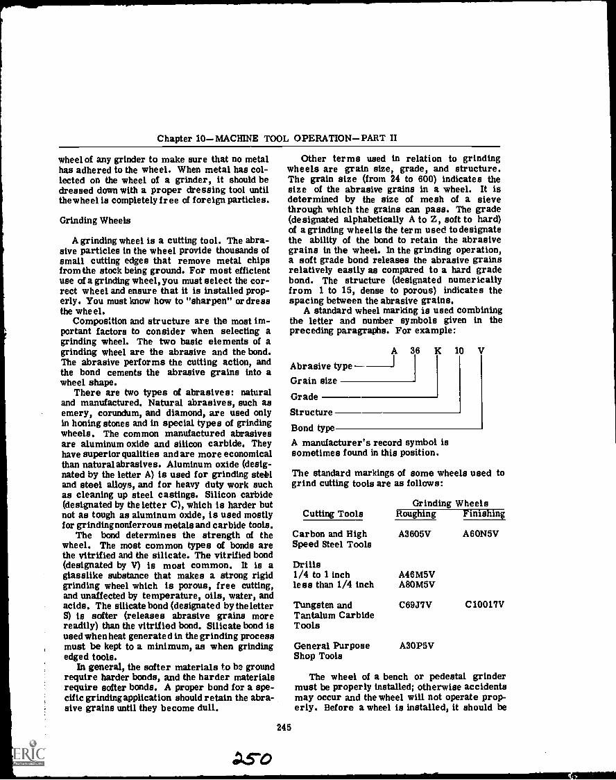
Chapter 10MACHINE TOOL OPERATIONPART II
wheel of any grinder to make sure that no metalhas adhered to the wheel. When metal has col-lected on the wheel of a grinder, it should bedressed down with a proper dressing tool untilthe wheel is completely free of foreign particles.
Grinding Wheels
A grinding wheel is a cutting tool. The abra-sive particles in the wheel provide thousands ofsmall cutting edges that remove metal chipsfrom the stock being ground. For most efficientuse of a grinding wheel, you must select the cor-rect wheel and ensure that it is installed prop-erly. You must know how to "sharpen" or dressthe wheel.
Composition and structure are the most im-portant factors to consider when selecting agrinding wheel. The two basic elements of agrinding wheel are the abrasive and the bond.The abrasive performs the cutting action, andthe bond cements the abrasive grains into awheel shape.
There are two types of abrasives: naturaland manufactured. Natural abrasives, such asemery, corundum, and diamond, are used onlyin honing stones and in special types of grindingwheels. The common manufactured abrasivesare aluminum oxide and silicon carbide. Theyhave superior qualities and are more economicalthan natural abrasives. Aluminum oxide (desig-nated by the letter A) is used for grinding stet'and steel alloys, and for heavy duty work suchas cleaning up steel castings. Silicon carbide(designated by the letter C), which is harder butnot as tough as aluminum oxide, is used mostlyfor grinding nonferrous metals and carbide tools.
The bond determines the strength of thewheel. The most common types of bonds arethe vitrified and the silicate. The vitrified bond(designated by V) is most common. It is aglasslike substance that makes a strong rigidgrinding wheel which is porous, free cutting,and unaffected by temperature, oils, water, andacids. The silicate bond (designated by the letterS) is softer (releases abrasive grains morereadily) than the vitrified bond. Silicate bond isused when heat generated in the grinding processmust be kept to a minimum, as when grindingedged tools.
In general, the softer materials to be groundrequire harder bonds, and the harder materialsrequire softer bonds. A proper bond for a spe-cific grinding application should retain the abra-sive grains until they become dull.
Other terms used in relation to grindingwheels are grain size, grade, and structure.The grain size (from 24 to 600) indicates thesize of the abrasive grains in a wheel. It isdetermined by the size of mesh of a sievethrough which the grains can pass. The grade(designated alphabetically A to Z, soft to hard)of a grinding wheel is the term used todesignatethe ability of the bond to retain the abrasivegrains in the wheel. In the grinding operation,a soft grade bond releases the abrasive grainsrelatively easily as compared to a hard gradebond. The structure (designated numericallyfrom 1 to 15, dense to porous) indicates thespacing between the abrasive grains.
A standard wheel marking is used combiningthe letter and number symbols given in thepreceding paragraphs. For example:
A 36 K
Grain sizeAbrasive type ---I
Grade
Structure
Bond type
245
10 V
A manufacturer's record symbol issometimes found in this position.
The standard markings of some wheels used togrind cutting tools are as follows:
Grinding WheelsCutting Tools Roughing Finishing
Carbon and High A3605V A60N5VSpeed Steel Tools
Drills1/4 to 1 inchless than 1/4 inch
A46M5VA80M5V
Tungsten and C69J7V C10017VTantalum CarbideTools
General Purpose A30P5VShop Tools
The wheel of a bench or pedestal grindermust be properly installed; otherwise accidentsmay occur and the wheel will not operate prop-erly. Before a wheel is installed, it should be
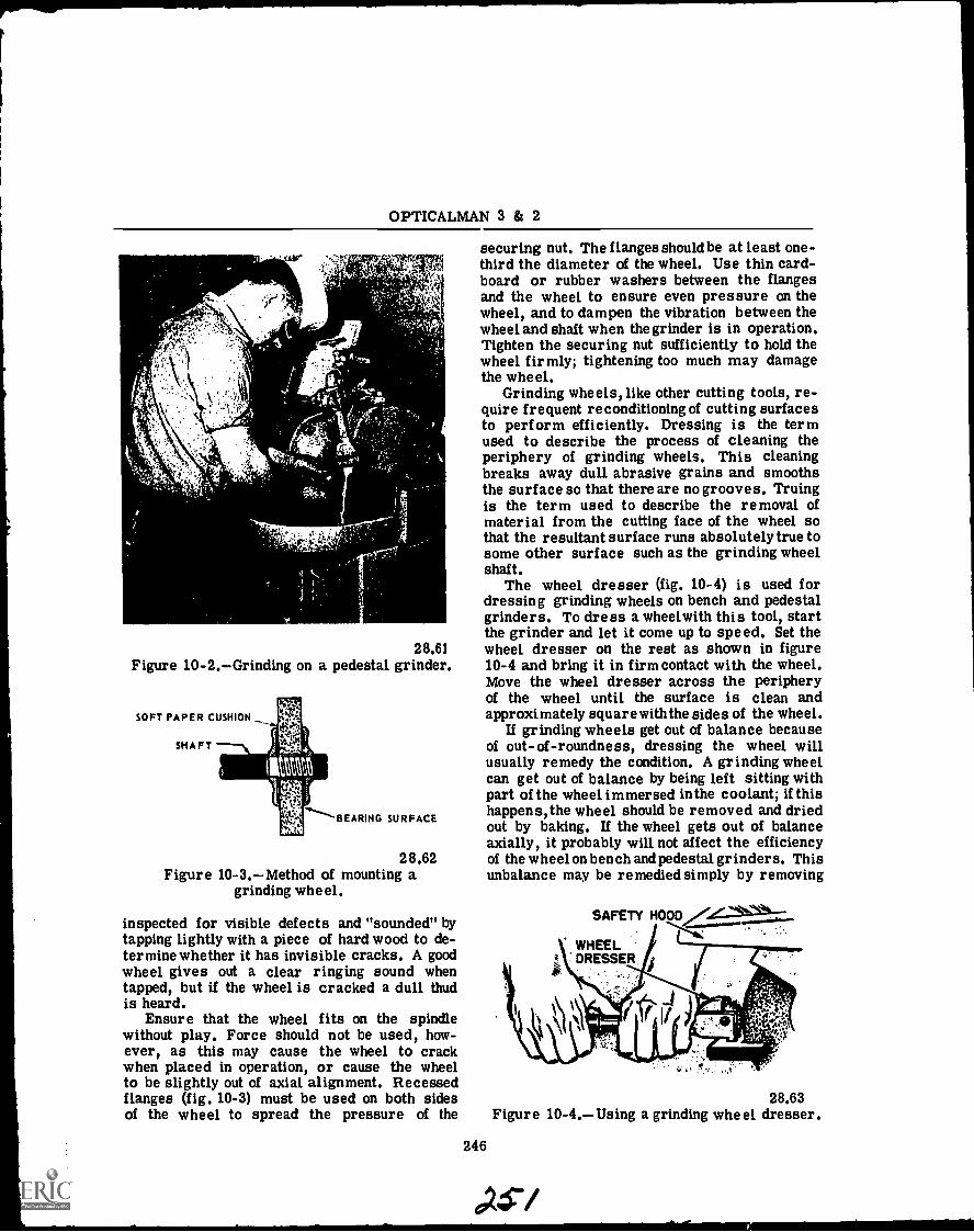
OPTICALMAN 3 & 2
'
yr
' A'7
,..!. 4
...4?".'1
28.61Figure 10-2.Grinding on a pedestal grinder.
SOFT PAPER CUSHION
SHAFT
BEARING SURFACE
28.62Figure 10-3.Method of mounting a
grinding wheel.
inspected for visible defects and "sounded" bytapping lightly with a piece of hard wood to de-termine whether it has invisible cracks. A goodwheel gives out a clear ringing sound whentapped, but if the wheel is cracked a dull thudis heard.
Ensure that the wheel fits on the spindlewithout play. Force should not be used, how-ever, as this may cause the wheel to crackwhen placed in operation, or cause the wheelto be slightly out of axial alignment. Recessedflanges (fig. 10-3) must be used on both sidesof the wheel to spread the pressure of the
securing nut. The flanges should be at least one-third the diameter of the wheel. Use thin card-board or rubber washers between the flangesand the wheel to ensure even pressure on thewheel, and to dampen the vibration between thewheel and shaft when the grinder is in operation.Tighten the securing nut sufficiently to hold thewheel firmly; tightening too much may damagethe wheel.
Grinding wheels, like other cutting tools, re-quire frequent reconditioning of cutting surfacesto perform efficiently. Dressing is the termused to describe the process of cleaning theperiphery of grinding wheels. This cleaningbreaks away dull abrasive grains and smoothsthe surface so that there are no grooves. Truingis the term used to describe the removal ofmaterial from the cutting face of the wheel sothat the resultant surface runs absolutely true tosome other surface such as the grinding wheelshaft.
The wheel dresser (fig. 10-4) is used fordressing grinding wheels on bench and pedestalgrinders. To dress a wheelwith this tool, startthe grinder and let it come up to speed. Set thewheel dresser on the rest as shown in figure10-4 and bring it in firm contact with the wheel.Move the wheel dresser across the peripheryof the wheel until the surface is clean andapproximately square with the sides of the wheel.
If grinding wheels get out of balance becauseof out-of-roundness, dressing the wheel willusually remedy the condition. A grinding wheelcan get out of balance by being left sitting withpart of the wheel immersed in the coolant; if thishappens, the wheel should be removed and driedout by baking. If the wheel gets out of balanceaxially, it probably will not affect the efficiencyof the wheel on bench and pedestal grinders. Thisunbalance may be remedied simply by removing
SAFETY HOODVL.WHEELDRESSER,
Figure 10-4.Using
246
a grinding wheel28.63
dresser.
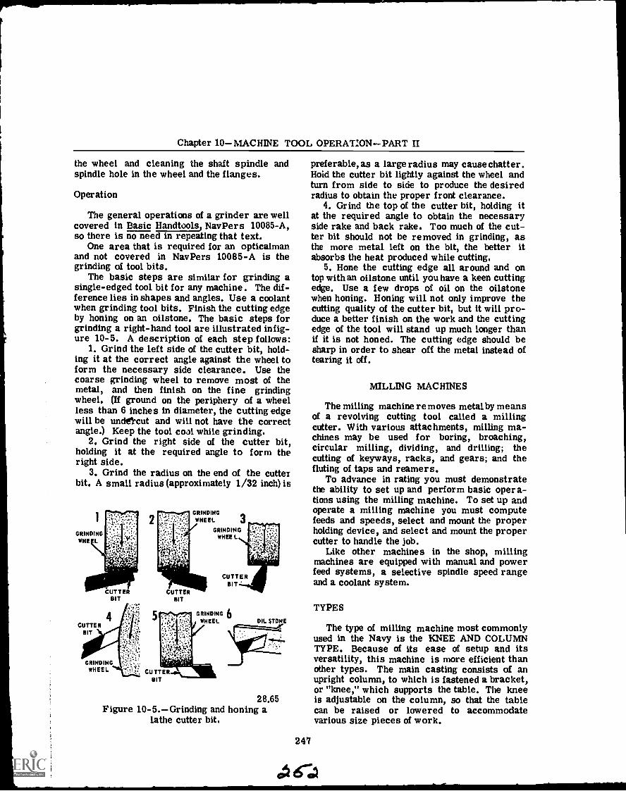
Chapter 10MACHINE TOOL OPERATIONPART II
the wheel and cleaning the shaft spindle andspindle hole in the wheel and the flanges.
Operation
The general operations of a grinder are wellcovered in Basic Handtools, NavPers 10085-A,so there is no need in repeating that text.
One area that is required for an opticalmanand not covered in NavPers 10085-A is thegrinding of tool bits.
The basic steps are similar for grinding asingle-edged tool bit for any machine. The dif-ference lies in shapes and angles. Use a coolantwhen grinding tool bits. Finish the cutting edgeby honing on an oilstone. The basic steps forgrinding a right-hand tool are illustrated in fig-ure 10-5. A description of each step follows:
1. Grind the left side of the cutter bit, hold-ing it at the correct angle against the wheel toform the necessary side clearance. Use thecoarse grinding wheel to remove most of themetal, and then finish on the fine grindingwheel. (If ground on the periphery of a wheelless than 6 inches in diameter, the cutting edgewill be undercut and will not have the correctangle.) Keep the tool coal while grinding.
2. Grind the right side of the cutter bit,holding it at the required angle to form theright side.
3. Grind the radius on the end of the cutterbit. A small radius (approximately 1/32 inch) is
GRINDINGWHEEL
GRINDINGWHEEL
GRINDINGWHEE L
CUT TERBIT
CUTTERBIT
CUTTERBIT
GRINDING 6WHEEL
GRINDINGWHEEL
OIL ;TONE
28.65Figure 10-5.Grinding and honing a
lathe cutter bit.
preferable, as a large radius may cause chatter.Hoid the cutter bit lightly against the wheel andturn from side to side to produce the desiredradius to obtain the proper front clearance.
4. Grind the top of the cutter bit, holding itat the required angle to obtain the necessaryside rake and back rake. Too much of the cut-ter bit should not be removed in grinding, asthe more metal left on the bit, the better itabsorbs the heat produced while cutting,
5. Hone the cutting edge all around and ontop with an oilstone until you have a keen cuttingedge. Use a few drops of oil on the oilstonewhen honing. Honing will not only improve thecutting quality of the cutter bit, but it will pro-duce a better finish on the work and the cuttingedge of the tool will stand up much longer thanif it is not honed. The cutting edge should besharp in order to shear off the metal instead oftearing it off.
247
MILLING MACHINES
The milling machine removes metal by meansof a revolving cutting tool called a millingcutter. With various attachments, milling ma-chines may be used for boring, broaching,circular milling, dividing, and drilling; thecutting of keyways, racks, and gears; and thefluting of taps and reamers.
To advance in rating you must demonstratethe ability to set up and perform basic opera-tions using the milling machine. To set up andoperate a milling machine you must computefeeds and speeds, select and mount the properholding device, and select and mount the propercutter to handle the job.
Like other machines in the shop, millingmachines are equipped with manual and powerfeed systems, a selective spindle speed rangeand a coolant system.
TYPES
The type of milling machine most commonlyused in the Navy is the KNEE AND COLUMNTYPE. Because of its ease of setup and itsversatility, this machine is more efficient thanother types. The main casting consists of anupright column, to which is fastened a bracket,or "knee," which supports the table. The kneeis adjustable on the column, so that the tablecan be raised or lowered to accommodatevarious size pieces of work.
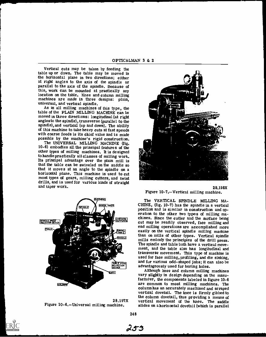
OPTICALMAN 3 & 2
Vertical cuts may be taken by feeding thetable up or down. The table may be moved inthe horizontal plane in two directions; eitherat right angles to the axis of the spindle orparallel to the axis of the spindle. Because ofthis, work can be mounted at practically anylocation on the table. Knee and column millingmachines are made in three designs: plain,universal, and vertical spindle.
As in all milling machines of this type, thetable of the PLAIN MILLING MACHINE can bemoved in three directions: longitudinal (at rightanglesto the spindle), transverse (parallel to thespindle), and vertical (up and down). The abilityof this machine to take heavy cuts at fast speedswith coarse feeds is its chief value and is madepossible by the machine's rigid construction.
The UNIVERSAL MILLING MACHINE (fig.10-6) embodies all the principal features of theother types of milling machines. It is designedto handle practically all classes of milling work.Its principal advantage over the plain mill isthat the table can be swiveled on the saddle sothat it moves at an angle to the spindle on ahorizontal plane. This machine is used to cutmost types of gears, milling cutters, and twistdrills, and is used for various kinds of straightand taper work.
'SPINDLE SPEEDSELECTION DEVICE
28.197XFigure 10-6.Universal milling machine.
248
28.198XFigure 10-7.Vertical milling machine.
The VERTICAL SPINDLE MILLING MA-CHINE, (fig. 10-7) has the spindle in a verticalposition and is similar in construction and op-eration to the other two types of milling ma-chines. Since the cutter and the surface beingcut may be readily observed, face milling andend milling operations are accomplished moreeasily on the vertical spindle milling machinethan on mills of other types. Vertical spindlemills embody the principles of the drill press.The spindle and table both have a vertical move-ment, and the table also has longitudinal andtransverse movement. This type of machine isused for face milling, profiling, and die sinking,and for various odd-shaped jobs; it can also beadvantageously used for boring holes.
Although knee and column milling machinesvary slightly in design depending on the manu-facturer, the components labeled in figure 10-6are common to most milling machines. Thecolumn has an accurately machined and scrapedvertical dovetail. The knee is firmly gibbed tothe column dovetail, thus providing a means ofvertical movement of the knee. The saddleslides on a horizontal dovetail (which is parallel
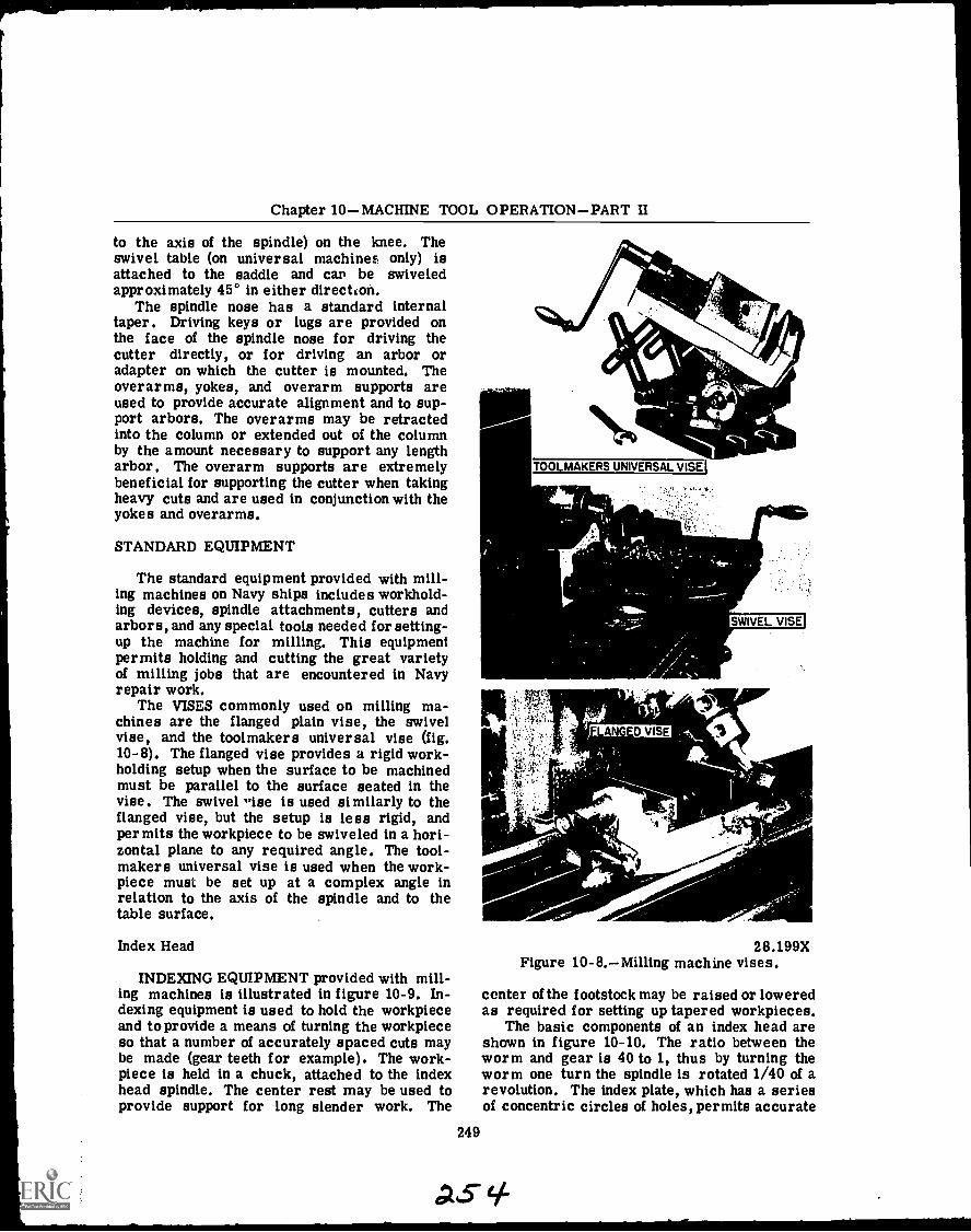
Chapter 10MACHINE TOOL OPERATIONPART II
to the axis of the spindle) on the knee. Theswivel table (on universal machine: only) isattached to the saddle and can be swiveledapproximately 45° in either directkon.
The spindle nose has a standard internaltaper. Driving keys or lugs are provided onthe face of the spindle nose for driving thecutter directly, or for driving an arbor oradapter on which the cutter is mounted. Theoverarms, yokes, and overarm supports areused to provide accurate alignment and to sup-port arbors. The overarms may be retractedinto the column or extended out of the columnby the amount necessary to support any lengtharbor. The overarm supports are extremelybeneficial for supporting the cutter when takingheavy cuts and are used in conjunction with theyokes and overarms.
STANDARD EQUIPMENT
The standard equipment provided with mill-ing machines on Navy ships includes workhold-ing devices, spindle attachments, cutters andarbors, and any special tools needed for setting-up the machine for milling. This equipmentpermits holding and cutting the great varietyof milling jobs that are encountered in Navyrepair work.
The VISES commonly used on milling ma-chines are the flanged plain vise, the swivelvise, and the toolmakers universal vise (fig.10-8). The flanged vise provides a rigid work-holding setup when the surface to be machinedmust be parallel to the surface seated in thevise. The swivel 'rise is used similarly to theflanged vise, but the setup is less rigid, andpermits the workpiece to be swiveled in a hori-zontal plane to any required angle. The tool-makers universal vise is used when the work-piece must be set up at a complex angle inrelation to the axis of the spindle and to thetable surface.
Index Head
INDEXING EQUIPMENT provided with mill-ing machines is illustrated in figure 10-9. In-dexing equipment is used to hold the workpieceand to provide a means of turning the workpieceso that a number of accurately spaced cuts maybe made (gear teeth for example). The work-piece is held in a chuck, attached to the indexhead spindle. The center rest may be used toprovide support for long slender work. The
249
TOOLMAKERS UNIVERSAL VISE'
AIL
A
,t
cc -
SWIVEL VISE
_FINGED VISE
28.199XFigure 10-8.Milling machine vises.
center of the footstock may be raised or loweredas required for setting up tapered workpieces.
The basic components of an index head areshown in figure 10-10. The ratio between theworm and gear is 40 to 1, thus by turning theworm one turn the spindle is rotated 1/40 of arevolution. The index plate, which has a seriesof concentric circles of holes, permits accurate
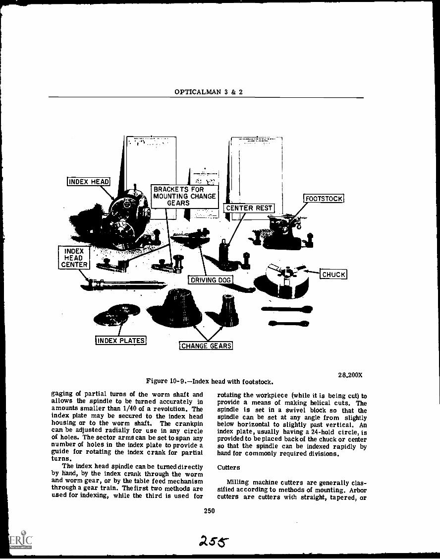
OPTICALMAN 3 & 2
CENTER REST
INDEXHEAD
CENTER
DRIVING DOG
INDEX PLATESCHANGE GEARS
28.200XFigure 10-9.Index head with footstock.
gaging of partial turns of the worm shaft andallows the spindle to be turned accurately inamounts smaller than 1/40 of a revolution. Theindex plate may be secured to the index headhousing or to the worm shaft. The crankpincan be adjusted radially for use in any circleof holes. The sector arms can be set to span anynumber of holes in the index plate to provide aguide for rotating the index crank for partialturns.
The index head spindle can be turned directlyby hand, by the index crank through the wormand worm gear, or by the table feed mechanismthrough a gear train. The first two methods areused for indexing, while the third is used for
rotating the workpiece (while it is being cut) toprovide a means of making helical cuts. Thespindle is set in a swivel block so that thespindle can be set at any angle from slightlybelow horizontal to slightly past vertical. Anindex plate, usually having a 24-hold circle, isprovided to be placed back of the chuck or centerso that the spindle can be indexed rapidly byhand for commonly required divisions.
Cutters
Milling machine cutters are generally clas-sified according to methods of mounting. Arborcutters are cutters with straight, tapered, or
250
56-

Chapter 10MACHINE TOOL OPERATIONPART II
SECTOR ARM
INDEX HEADSPINDLE
INDEX PIN
INDEXPLATE
WORM GEAR
INDEX CRANK
WORM SHAFT WORM
SECTOR ARM
28.201Figure 10-10.Index head mechanism.
28.204XFigure 10-11.Arbors, sleeves, and
special adapters.
threaded holes for mounting on an arbor. Themost common type has a straight hole witrikeyway through it or across one end. By meansof a key inserted in this keyway, the cutter isprevented from turning on the arbor. Shankcutters have straight or tapered shanks and aremounted in collets or adapters. Facing cuttersare attached to either a stub arbor or directlyto the milling machine spindle. Figure 10-11illustrates various arbors, sleeves, and adaptersfor mounting cutters.
The millingcutters with which you will comein contact in the normal course of your work as
an Opticalman are illustrated in figure 10.12.These cutters are made from carbon steel, high-speed steel, Stellite, or tool steelwith cementedcarbide teeth. The types of cutters most used,and the operations to which they are best suited,are as follows:
PLAIN MILLING CUTTERS (numbers 27 and30 of fig. 10-12) are the most widely used of allcutters. They are used for millingflat surfacesparallel to the cutter's axis. The cutter iscylindrical and has teeth cut on the peripheryonly. Plain milling cutters are made in a varietyof diameters andwidths. The teeth may be eitherstraight or spiral in shape, but the latter typeis generally used when the cutter is more than3/4 inch wide. A cutter tooth that is straightor parallel to its axis receives a distinct shockas the tooth starts to cut. To eliminate thisshock and thereby produce a free cutting action,cutters are often made with helical teeth. Aspirally gashed cutter, particularly when usedon wide surfaces, gives a much smoother. resultthan a straight gashed cutter. Spirally gashedcutters also require less power to operate and,since the stress on the cutter is relieved, thetendency to chatter is reduced. When the plainmilling cutter is made with relatively few teethand a fairly steep angle of spiral, the cutter iscommonly called a coarse tooth cutter. Suchcutters are used because of their ability to re-move considerable quantities of metal with mini-mum power consumption. Plain mills with veryfew teeth and helical milling cutters have a verysteep angle of spiral. They are particularlyefficient on heavy slabbing cuts. Owing to theshearing action of the teeth, they can be used toadvantage in removing an uneven amount ofstock without gouging. They are made in both"hole" and "arbor" types for milling formsfrom solid metal.
SIDE MILLING CUTTERS (numbers 14, 28,and 29 of fig. 10-12) are comparatively narrowmilling cutters and may have teeth on one sideonly or on both sides as well as on the outersurface. When used in pairs, with an appropriatespacer between them, these cutters can millparallel sides such as on bolt heads, tongues,nuts, etc. Side milling cutters more than 8inches in diameter are usually made with in-serted teeth. Another type of side cutter is theSTAGGERED-TOOTH CUTTER, designed fordeep cuts in steel (number 28 of fig. 10-12).
METAL SLITTING SAWS (numbers 1, 5, and17 of fig. 10-12) used on milling machines areessentially thin, plain milling cutters. The
251
c675-6-

OPTICALMAN 3 & 2
14 25
t A14102.
-23
22 Itokadia-
I
1. Metal slitting saw. 17. Metal slitting saw.2. Involute spur gear cutter (undercut teeth). 18. Concave cutter.3. Spiral end mill, taper shank. 19. Ball end mills.4. Two-lipped spiral mill, taper shank. 20. Long single-end end mill.5. Metal staggered-tooth slitting saw. 21. Double-end end mills.6. Long two-lipped end mill, single end. 22. Two-lipped long single-end end mill.7. Long spiral end mills, double end. 23. Screw slotting cutter.8. Two-lipped spiral end mill, double end. 24. Two-lipped spiral end mill, straight9. Corner rounding cutter. shank.
10. Involute form cutter. 25. Angular cutter.11. Spiral end mill, cam-locking. 26. Spiral end mill, straight shank.12. Long two-lipped spiral end mill, double 27. Plain heavy duty milling cutter.
end. 28. Staggered tooth side milling cutter.13. Long spiral err mill, single end. 29. Side milling cutter.14. Half side milling cutter. 30. Helical plain milling cutter.15. Convex cutter. 31. Shell end miss for use with shell end mill16. Woodruff kevseat cutter. arbor.
28.205XFigure 10-12.-Milling machine cutters.
252
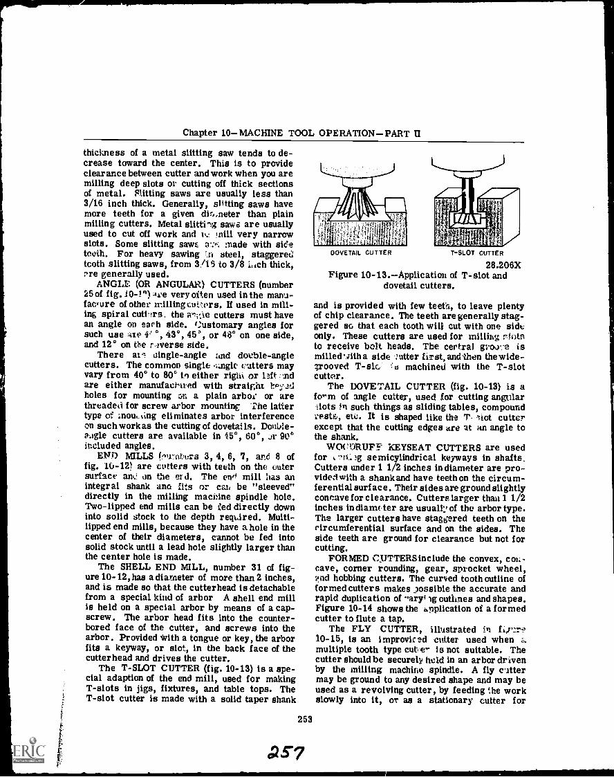
Chapter 10MACHINE TOOL OPERATIONPART II
thickness of a metal slitting saw tends to de-crease toward the center. This is to provideclearance between cutter and work when you aremilling deep slots or cutting off thick sectionsof metal. Pitting saws are usually less than3/16 inch thick. Generally, slitting saws havemore teeth for a given dir,,neter than plainmilling cutters. Metal slitting saws are usuallyused to cut off work and h., mill very narrowslots. Some slitting saws a :ir. made with sideteeth. For heavy sawing *.ti steel, staggeredtooth slitting saws, from 3/15 to 3/8 iiich thick,cre generally used.
ANGLE (OR ANGULAR) CUTTERS (number25 of fig. 0-1") Ave very often used in the manu-facture of other millingcuiers. If used in mill-ing spiral cuttrs the arv,ie cutters must havean angle on earh side. (:ustomary angles forsuch use :itts 0, 43°, 45°, or 48° on one side,and 12° on the r.iverse side.
There at aingle-angle and double-anglecutters. The common single (ratters mayvary from 40° to 80° to either right or left ....ridare either manufachred with straight ircyJdholes for mounting cal a plain arbor or arethreaded for screw arbor mounting The lattertype of Inointing eliminates arbor interferenceon such work as the cutting of dovetails. Donia-aogle cutters are available in 15°, 60°, ..)1. 90°included angles.
ENO MILLS frnr.ubors 3, 4, 6, 7, and 8 offig. 10-12) are cotters with teeth on the outersurface am.' on the er d. The ens' mill lias anintegral shank ano :its or cars be "sleeved"directly in the milling machine spindle hole.Two-lipped end mills can be led directly downinto solid stock to the depth reqdred. Multi-lipped end mills, because they have a hole in thecenter of their diameters, cannot be fed intosolid stock until a lead hole slightly larger thanthe center hole is made.
The SHELL END MILL, number 31 of fig-ure 10-12,has a diameter of more than 2 inches,and is made so that the cutterhead is detachablefrom a special kind of arbor A shell end millis held on a special arbor by means of a cap-screw. The arbor head fits into the counter-bored face of the cutter, and screws into thearbor. Provided with a tongue or key, the arborfits a keyway, or slot, in the back face of thecutterhead and drives the cutter.
The T-SLOT CUTTER (fig. 10-13) is a spe-cial adaption of the end mill, used for makingT-slots in jigs, fixtures, and table tops. TheT-slot cutter is made with a solid taper shank
DOVETAIL CUTTER T-SLOT CUTTER
28.206XFigure 10-13.Application of T-slot and
dovetail cutters.
and is provided with few teeth, to leave plentyof chip clearance. The teeth are generally stag-gered so that each tooth will cut with one sideonly. These cutters are used for milling r(titsto receive bolt heads. The certral groo-..e ismilled ',nth a side utter first, and then the w ide-grooved T-slc machined with the T-slotcutter.
The DOVETAIL CUTTER (fig. 10-13) is aform of angle cutter, used for cutting angularlots in such things as sliding tables, compound
reste, etc. It is shaped like the T. .Lot cutterexcept that the cutting edges are at an angle tothe shank.
WOCORUFY KEYSEAT CUTTERS are usedfor -a. )g semicylindrical keyways in shafts.Cutters under 1 1/2 inches in diameter are pro-vided with a shank and have teeth on the circum-ferential surf ace. Their sides are ground slightlyconcave for clearance. Cutters larger than 1 1/2inches India= ter are usually of the arbor type.The larger cutters have staggered teeth on thecircumferential surface and on the sides. Theside teeth are ground for clearance but not forcutting.
FORMED C_UTTERSinclude the convex, cot: -cave, corner rounding, gear, sprocket wheel,.e.nd hobbing cutters. The curved tooth outline offormed cutters makes possible the accurate andrapid duplication of aryig outlines and shapes.Figure 10-14 shows the Application of a formedcutter to flute a tap.
The FLY CUTTER, illustrated in f.,7,2r.?10-15, is an improvised cotter used whenmultiple tooth type cut e- is not suitable. Thecutter should be securely held in an arbor drivenby the milling machine spindle. A fly cittermay be ground to any desired shape and may beused as a revolving cutter, by feeding :he workslowly into it, or as a stationary cutter for
253
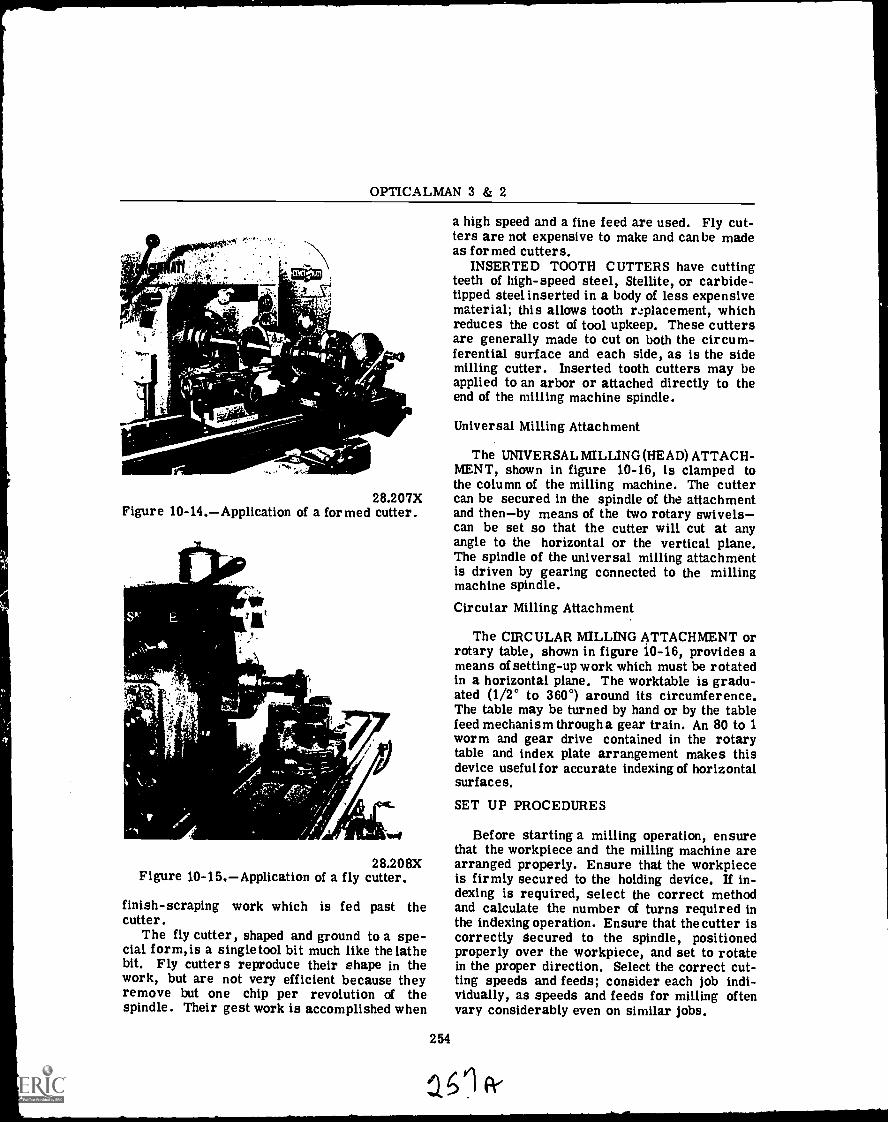
OPTICALMAN 3 & 2
28.207XFigure 10-14.Application of a formed cutter.
28.208XFigure 10-15.Application of a fly cutter.
finish-scraping work which is fed past thecutter.
The fly cutter, shaped and ground to a spe-cial form, is a singletool bit much like the lathebit. Fly cutters reproduce their shape in thework, but are not very efficient because theyremove but one chip per revolution of thespindle. Their gest work is accomplished when
a high speed and a fine feed are used. Fly cut-ters are not expensive to make and can be madeas formed cutters.
INSERTED TOOTH CUTTERS have cuttingteeth of high-speed steel, Stellite, or carbide-tipped steel inserted in a body of less expensivematerial; this allows tooth replacement, whichreduces the cost of tool upkeep. These cuttersare generally made to cut on both the circum-ferential surface and each side, as is the sidemilling cutter. Inserted tooth cutters may beapplied to an arbor or attached directly to theend of the milling machine spindle.
Universal Milling Attachment
The UNIVERSAL MILLING (HEAD) ATTACH-MENT, shown in figure 10-16, is clamped tothe column of the milling machine. The cuttercan be secured in the spindle of the attachmentand thenby means of the two rotary swivelscan be set so that the cutter will cut at anyangle to the horizontal or the vertical plane.The spindle of the universal milling attachmentis driven by gearing connected to the millingmachine spindle.
Circular Milling Attachment
The CIRCULAR MILLING ATTACHMENT orrotary table, shown in figure 10-16, provides ameans of setting-up work which must be rotatedin a horizontal plane. The worktable is gradu-ated (1/2° to 360°) around its circumference.The table may be turned by hand or by the tablefeed mechanism through a gear train. An 80 to 1worm and gear drive contained in the rotarytable and index plate arrangement makes thisdevice useful for accurate indexing of horizontalsurfaces.
SET UP PROCEDURES
Before starting a milling operation, ensurethat the workpiece and the milling machine arearranged properly. Ensure that the workpieceis firmly secured to the holding device. If in-dexing is required, select the correct methodand calculate the number of turns required inthe indexing operation. Ensure that the cutter iscorrectly Secured to the spindle, positionedproperly over the workpiece, and set to rotatein the proper direction. Select the correct cut-ting speeds and feeds; consider each job indi-vidually, as speeds and feeds for milling oftenvary considerably even on similar jobs.
254
a0
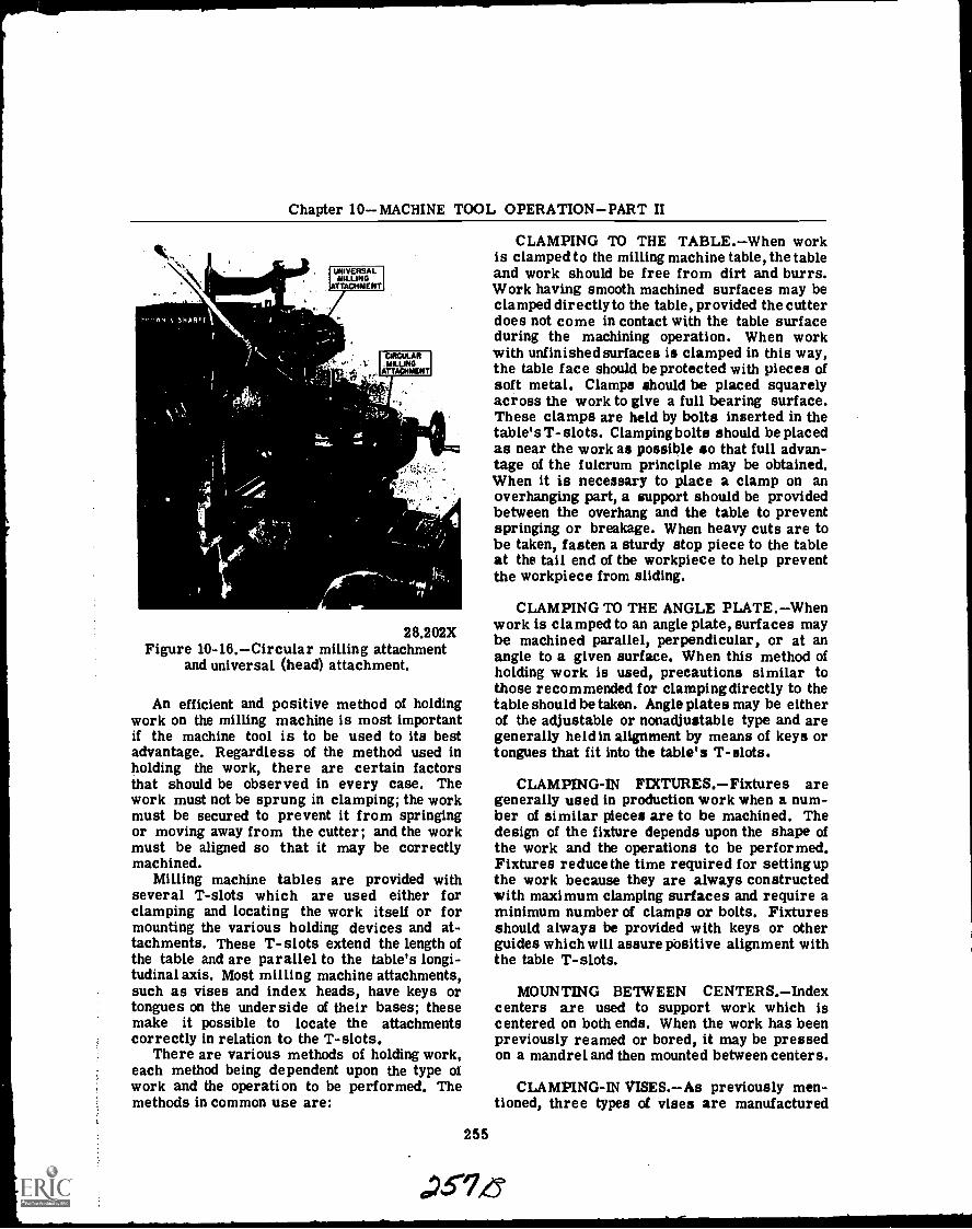
Chapter 10MACHINE TOOL OPERATIONPART II
28.202XFigure 10-16.Circular milling attachment
and universal (head) attachment.
An efficient and positive method of holdingwork on the milling machine is most importantif the machine tool is to be used to its bestadvantage. Regardless of the method used inholding the work, there are certain factorsthat should be observed in every case. Thework must not be sprung in clamping; the workmust be secured to prevent it from springingor moving away from the cutter; and the workmust be aligned so that it may be correctlymachined.
Milling machine tables are provided withseveral T-slots which are used either forclamping and locating the work itself or formounting the various holding devices and at-tachments. These T-slots extend the length ofthe table and are parallel to the table's longi-tudinal axis. Most milling machine attachments,such as vises and index heads, have keys ortongues on the underside of their bases; thesemake it possible to locate the attachmentscorrectly in relation to the T-slots.
There are various methods of holding work,each method being dependent upon the type ofwork and the operation to be performed. Themethods in common use are:
255
CLAMPING TO THE TABLE.When workis clamped to the milling machine table, the tableand work should be free from dirt and burrs.Work having smooth machined surfaces may beclamped directly to the table, provided the cutterdoes not come in contact with the table surfaceduring the machining operation. When workwith unfinished surfaces is clamped in this way,the table face should be protected with pieces ofsoft metal. Clamps should be placed squarelyacross the work to give a full bearing surface.These clamps are held by bolts inserted in thetable's T- slots. Clamping bolts should be placedas near the work as possible so that full advan-tage of the fulcrum principle may be obtained.When it is necessary to place a clamp on anoverhanging part, a support should be providedbetween the overhang and the table to preventspringing or breakage. When heavy cuts are tobe taken, fasten a sturdy stop piece to the tableat the tail end of the workpiece to help preventthe workpiece from sliding.
CLAMPING TO THE ANGLE PLATE.Whenwork is clamped to an angle plate, surfaces maybe machined parallel, perpendicular, or at anangle to a given surface. When this method ofholding work is used, precautions similar tothose recommended for clampingdirectly to thetable should be taken. Angle plates may be eitherof the adjustable or nonadjustable type and aregenerally held in alignment by means of keys ortongues that fit into the table's T-slots.
CLAMPING-IN FIXTURES.Fixtures aregenerally used in production work when a num-ber of similar pieces are to be machined. Thedesign of the fixture depends upon the shape ofthe work and the operations to be performed.Fixtures reducethe time required for settingupthe work because they are always constructedwith maximum clamping surfaces and require aminimum number of clamps or bolts. Fixturesshould always be provided with keys or otherguides which will assure positive alignment withthe table T-slots.
MOUNTING BETWEEN CENTERS.Indexcenters are used to support work which iscentered on both ends. When the work has beenpreviously reamed or bored, it may be pressedon a mandrel and then mounted between centers.
CLAMPING-IN VISES.As previously men-tioned, three types of vises are manufactured
a.73-7,6

OPTICALMAN 3 & 2
for holding milling machine work. These viseshave locating keys or tongues on the undersideof the base so that they may be located cor-rectly in relation to the T-slots on the millingmachine table.
DIRECT INDEXING.Direct indexing, some-times called rapid indexing, makes use of thedirect index plate which is mounted just back ofthe work end of the index head spindle (fig.10-17). With the index pin out of contact withthe direct index plate, disengage the spindle andindex by turning the spindle by hand. To dividework into two equal parts, the index pin shouldbe disengaged and the plate and spindle revolveduntil 11 holes in a 24-hole circle have passedthe index pin. The index pin is then inserted intothe 12th hole in the plate to hold the spindle inthe proper position. IN ANY INDEXING OPER-ATION ALWAYS START COUNTING FROM THEHOLE ADJACENT TO THE CRANKPIN. Dur-ing heavy cutting operations, the spindle shouldbe clamped by means of the clamp screw torelieve strain on the index pin.
PLATEDIRECT INDEX
F.
28.209XFigure 10-17.Direct index plate.
PLAIN INDEXING. Plain indexing, ac-complished by using the universal index head, isgoverned by the number of times the index crankmust be turned to cause the work to make onerevolution. Charts specifying the required num-ber of turns or fractions of a turn and giving
the proper index plate for various divisions arefurnished by index head manufacturers. If thesecharts are unavailable, the required number ofturns and parts of turns may be determined bysimple calculation.
The number of turns of the index crank re-quired to index a fractional part of a revolutionis determined by dividing 40 by the number ofdivisions required. For example, if you are re-quired to make 40 divisions on a piece of work,40 would be divided by 40, indicating that onecomplete turn of the index crank is required foreach division. If 10 divisions were required, 40would be divided by 10 and 4 complete turns ofthe index crankwould be required for each divi-sion. Index plates are used to assist in makingthe division when the quotient of the ratio of theindex head and the division desired results in afraction, thus making it necessary to turn thecrank a part of a revolution in indexing. Thenumerator of the fraction, determined by divid-ing 40 by the number of divisions required, rep-resents the number of holes in a circle of holesthat the index crank should be moved for eachdesired division. The denominator of this frac-tion represents the number of holes in the cor-rect circle of holes which should be selected onthe index plate. For example, the calculationfor determining 800 divisions when an indexplate with 20 holes is available, is as follows:
40 1
800 20
or 1 hole on the 20-hole circle.When the fraction is such that none of the
available index plates contain the number ofholes represented by the denominator, multiplyboth the numerator and denominator by a com-mon multiplier. For example, the calculationfor determining 9 divisions when an index platehaving a 27-hole circle is available, is asfollows:
40 3 120 12-9- x-3- =-- =4
or 4 complete turns plus 12 holes on the 27-holecircle.
If the denominator of the fraction is largerthan the number of holes that are available in anindex plate, divide both the numerator and de-nominator by a common divisor that will give afraction in which the denominator representsthe number of holes for which the index plate
256

Chapter 10MACHINE TOOL OPERATIONPART II
is available. For example, the calculation fordetermining 76 divisions when an index platehaving a 19-hole circle is available, is as follows:
40 4 _ 1076 4 19
or 10 holes in the 19-hole circle.If when reducing the fraction, as discussed
in the foregoing paragraph, the denominatorbecomes so small that no available index platecontains the number of holes represented by thedenominator, the fraction should be raised toan available number. For example, the calcula-tion for determining 52 divisions when an indexplate with a 39-hole circle is available, is asfollows:
40.4 _10 3 _3052 4 13
or 30 holes in a 39-hole circle.
ANGULAR INDEXING.When it is necessaryto divide work into degrees or fractions ofdegrees by plain indexing, remember that oneturn of the index crank will rotate a point on thecircumference of the work 1/40 of a revolution.Since there are 360° in a circle, one turn of theindex crank will revolve the circumference ofthe work 1/40 of 360°, or 9°. Hence,when usingthe index plate and fractional parts of a turn, 2holes in an 18-hole circle equals 1°, 1 hole in a27-hole circle equals 2/3°, 3 holes in a 54-holecircle equals 1/2°, and 2 holes in a 54-holecircle equals 1/3°. To determine the number ofturns and parts of a turn of the index crank fora desired number of degrees, the number ofdegrees should be divided by 9, and the quotientwill represent the number of complete turns andfractions of a turn that the index crank should berotated. For example, the calculationfor deter-mining 15° when an index plate with a 54-holecircle is available, is as follows:
15 = 16 1369 9 54
or 1 complete turn plus 36 holes on the 54-holecircle. The calculation for determining 13 1/2 °when an index plate with an 18-hole circle isavailable, is as follows:
13.5 14:9
.13'1
or 1 complete turn plus 9 holes on the 18-holecircle.
When indexing angles are given in minutes,and approximate divisions are acceptable, move-ment of the index crank and the proper indexplate may be determined by the following cal-culations. The number of minutes representedby one turn of the index crank can be deter-mined by multiplying the number of degreescovered in one turn of the index crank by 60.Thus,
9° x 60' = 540'
Therefore, one turn of the index crank willrotate the index head spindle 540 minutes.
The number of minutes, 540, divided by thenumber of minutes in the division desired, indi-cates the total number of holes the index platecircleto be used should have. (Moving the indexcrank one hole will rotate the index head spindlethrough the desired number of minutes of angle.)This method of indexing can be used only forapproximate angles since ordinarily the quotientwill come out in mixed numbers or in numbersfor which there are no index plates available.However, when the quotient is nearly equal tothe number of holes in an available index plate,the nearest number of holes can be used and theerror will be very small. For example, the cal-culation for 24 minutes would be:
540 22.524 1
or one hole on the 22.5-hole circle. Since thereis no 22.5-hole circle on the index plate, a 23-hole circle plate would be used.
If a quotient is not approximately equal to anavailable circle of holes, then multiply by anytrial number which will give a product equal tothe number of holes in one of the available indexcircles. The crank can then be moved the re-quired number of holes to give the desired divi-sion. For example, the calculation for deter-mining 54 minutes when an index plate havinga 20-hole circle is available, is as follows:
257
540 10 2 2054 1 2 2
or 2 holes on the 20-hole circle.To mount a cutter on an arbor (fig. 10-18):1. Select an arbor having the same diam-
eter as the hole in the cutter.
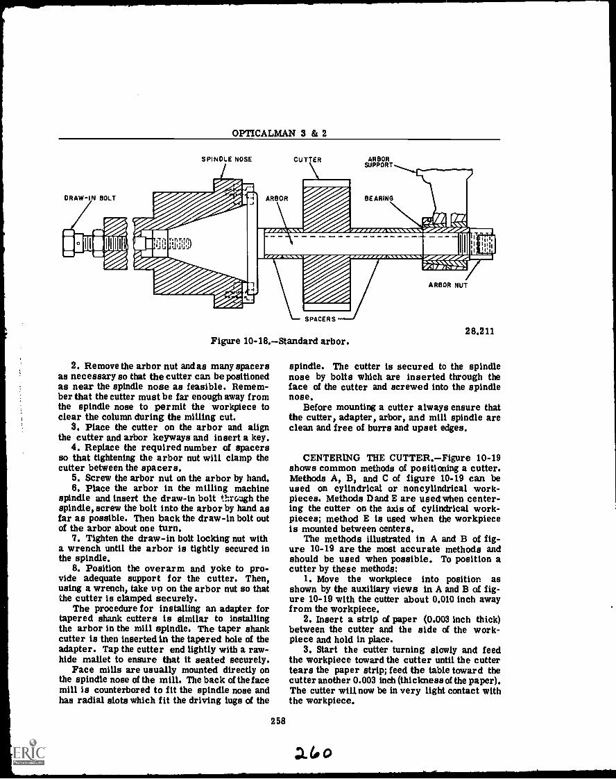
OPTICALMAN 3 & 2
SPINDLE NOSE
ARBOR
CUTTER ARBORSUPPORT
BEARING
1111
17 I I
Ill'
1
SPACERS
Figure 10-18.Standard arbor.
2. Remove the arbor nut and as many spacersas necessary so that the cutter can be positionedas near the spindle nose as feasible. Remem-ber that the cutter must be far enough away fromthe spindle nose to permit the workpiece toclear the column during the milling cut.
3. Place the cutter on the arbor and alignthe cutter and arbor keyways and insert a key.
4. Replace the required number of spacersso that tightening the arbor nut will clamp thecutter between the spacers.
5. Screw the arbor nut on the arbor by hand.6. Place the arbor in the milling machine
spindle and insert the draw-in bolt through thespindle, screw the bolt into the arbor by hand asfar as possible. Then back the draw-in bolt outof the arbor about one turn.
7. Tighten the draw-in bolt locking nut witha wrench until the arbor is tightly secured inthe spindle.
8. Position the overarm and yoke to pro-vide adequate support for the cutter. Then,using a wrench, take up on the arbor nut so thatthe cutter is clamped securely.
The procedure for installing an adapter fortapered shank cutters is similar to installingthe arbor in the mill spindle. The taper shankcutter is then inserted in the tapered hole of theadapter. Tap the cutter end lightly with a raw-hide mallet to ensure that it seated securely.
Face mills are usually mounted directly onthe spindle nose of the mill. The back of the facemill is counterbored to fit the spindle nose andhas radial slots which fit the driving lugs of the
258
mwwwwwwmmicem20/
ir1/1 11M
ARBOR NUT
28.211
spindle. The cutter is secured to the spindlenose by bolts which are inserted through theface of the cutter and screwed into the spindlenose.
Before mounting a cutter always ensure thatthe cutter, adapter, arbor, and mill spindle areclean and free of burrs and upset edges.
CENTERING THE CUTTER.Figure 10-19shows common methods of positioning a cutter.Methods A, B, and C of figure 10-19 can beused on cylindrical or noncylindrical work-pieces. Methods D and E are used when center-ing the cutter on the axis of cylindrical work-pieces; method E is used when the workpieceis mounted between centers.
The methods illustrated in A and B of fig-ure 10-19 are the most accurate methods andshould be used when possible. To position acutter by these methods:
1. Move the workpiece into position asshown by the auxiliary views in A and B of fig-ure 10-19 with the cutter about 0.010 inch awayfrom the workpiece.
2. Insert a strip of paper (0.003 inch thick)between the cutter and the side of the work-piece and hold in place.
3. Start the cutter turning slowly and feedthe workpiece toward the cutter until the cuttertears the paper strip; feed the table toward thecutter another 0.003 inch (thickness of the paper).The cutter will now be in very light contact withthe workpiece.
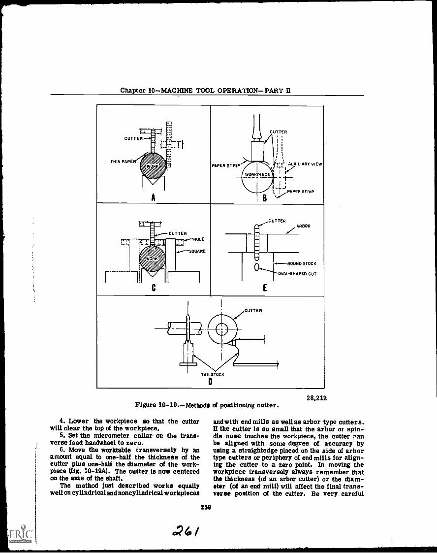
Chapter 10MACHINE TOOL OPERATIONPART II
rl:tz,CUTTER
,AUXILIARY VIEW
1
4-
mgCUTTER
THIN PAPER
=
7
/WO/RK/WORK
//7
t.-.4
-1--I1'l",,
PAPER STRIP
WORVIECEI
'T-7'
-1---
..;\ -,...1...,,PAPER STRIP
l ...CUTTER
...V
ARBOR
t-"Il
r -1I
MOWN
WORK
Ewe
/ /
CUTTERRULE
SQUARE
a.: 1
WIa4-ROUND STOCK
E
OVAL-SHAPED CUT
C
41%
1
CUTTER
iirIII
41
TAILSTOCK
0
Figure 10-19.Methods of positioning cutter.
4. Lower the workpiece so that the cutterwill clear the top of the workpiece.
5. Set the micrometer collar on the trans-verse feed handwheel to zero.
6. Move the worktable transversely by anamount equal to one-half the thickness of thecutter plus one-half the diameter of the work-piece (fig. 10-19A). The cutter is now centeredon the axis of the shaft.
The method just described works equallywell on cylindrical and noncylindrical workpieces
259
024/
28.212
and with end mills as well as arbor type cutters.If the cutter is so small that the arbor or spin-dle nose touches the workpiece, the cutter clanbe aligned with some degree of accuracy byusing a straightedge placed on the side of arbortype cutters or periphery of end mills for align-ing the cutter to a zero point. In moving theworkpiece transversely always remember thatthe thickness (of an arbor cutter) or the diam-eter (of an end mill) will affect the final trans-verse position of the cutter. Be very careful
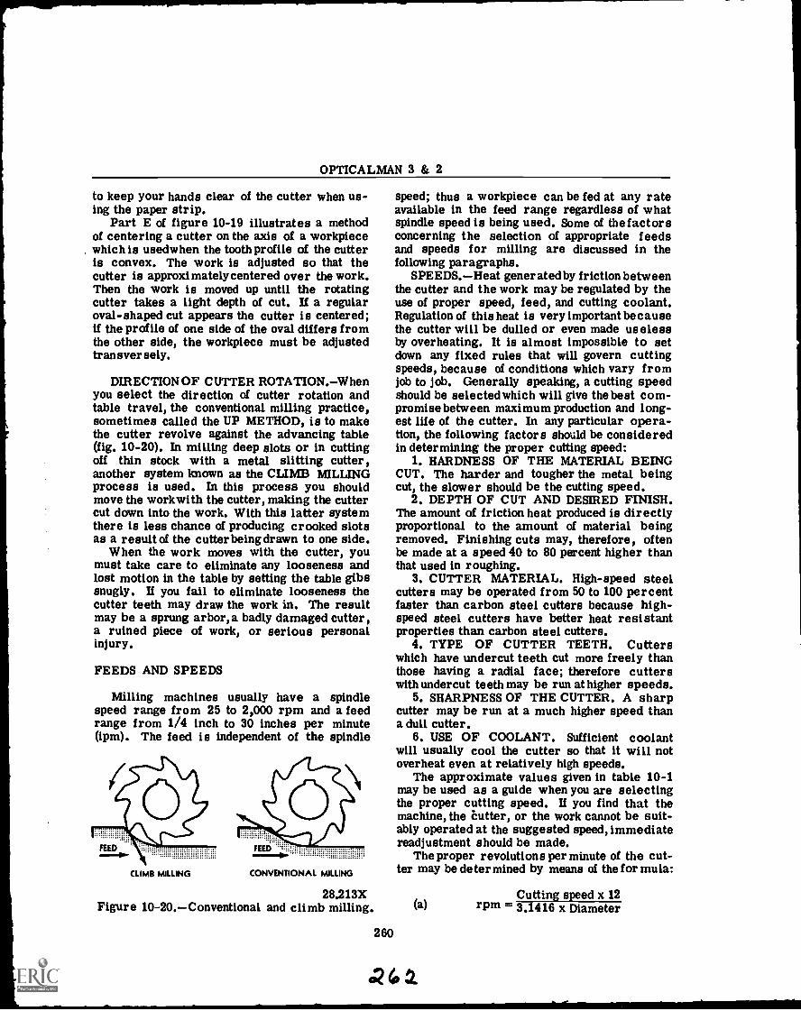
OPTICALMAN 3 & 2
to keep your hands clear of the cutter when us-ing the paper strip.
Part E of figure 10-19 illustrates a methodof centering a cutter on the axis of a workpiecewhich is usedwhen the tooth profile of the cutteris convex. The work is adjusted so that thecutter is approximately centered over the work.Then the work is moved up until the rotatingcutter takes a light depth of cut. If a regularoval-shaped cut appears the cutter is centered;if the profile of one side of the oval differs fromthe other side, the workpiece must be adjustedtransversely.
DIRECTION OF CUTTER ROTA TION.W henyou select the direction of cutter rotation andtable travel, the conventional milling practice,sometimes called the UP METHOD, is to makethe cutter revolve against the advancing table(fig. 10-20). In milling deep slots or in cuttingoff thin stock with a metal slitting cutter,another system known as the CLIMB MILLINGprocess is used. In this process you shouldmove the workwith the cutter, making the cuttercut down into the work. With this latter systemthere is less chance of producing crooked slotsas a result of the cutter being drawn to one side.
When the work moves with the cutter, youmust take care to eliminate any looseness andlost motion in the table by setting the table gibssnugly. If you fail to eliminate looseness thecutter teeth may draw the work in. The resultmay be a sprung arbor, a badly damaged cutter,a ruined piece of work, or serious personalinjury.
FEEDS AND SPEEDS
Milling machines usually have a spindlespeed range from 25 to 2,000 rpm and a feedrange from 1/4 inch to 30 inches per minute(ipm). The feed is independent of the spindle
CLIMB MILLING
FEED ""
CONVENTIONAL MILLING
28.213XFigure 10-20.Conventional and climb milling.
260
speed; thus a workpiece can be fed at any rateavailable in the feed range regardless of whatspindle speed is being used. Some of the factorsconcerning the selection of appropriate feedsand speeds for milling are discussed in thefollowing paragraphs.
SPEEDS. Heat generated by friction betweenthe cutter and the work may be regulated by theuse of proper speed, feed, and cutting coolant.Regulation of this heat is very important becausethe cutter will be dulled or even made uselessby overheating. It is almost impossible to setdown any fixed rules that will govern cuttingspeeds, because of conditions which vary fromjob to job. Generally speaking, a cutting speedshould be selected which will give the best com-promise between maximum production and long-est life of the cutter. In any particular opera-tion, the following factors should be consideredin determining the proper cutting speed:
1. HARDNESS OF THE MATERIAL BEINGCUT. The harder and tougher the metal beingcut, the slower should be the cutting speed.
2. DEPTH OF CUT AND DESIRED FINISH.The amount of friction heat produced is directlyproportional to the amount of material beingremoved. Finishing cuts may, therefore, oftenbe made at a speed 40 to 80 percent higher thanthat used in roughing.
3. CUTTER MATERIAL. High-speed steelcutters may be operated from 50 to 100 percentfaster than carbon steel cutters because high-speed steel cutters have better heat resistantproperties than carbon steel cutters.
4. TYPE OF CUTTER TEETH. Cutterswhich have undercut teeth cut more freely thanthose having a radial face; therefore cutterswith undercut teeth may be run at higher speeds.
5. SHARPNESS OF THE CUTTER. A sharpcutter may be run at a much higher speed thana dull cutter.
6. USE OF COOLANT. Sufficient coolantwill usually cool the cutter so that it will notoverheat even at relatively high speeds.
The approximate values given in table 10-1may be used as a guide when you are selectingthe proper cutting speed. If you find that themachine, the Cutter, or the work cannot be suit-ably operated at the suggested speed, immediatereadjustment should be made.
The proper revolutions per minute of the cut-ter may be determined by means of the formula:
Cutting speed x 12(a) rpm = 3.1416 x Diameter
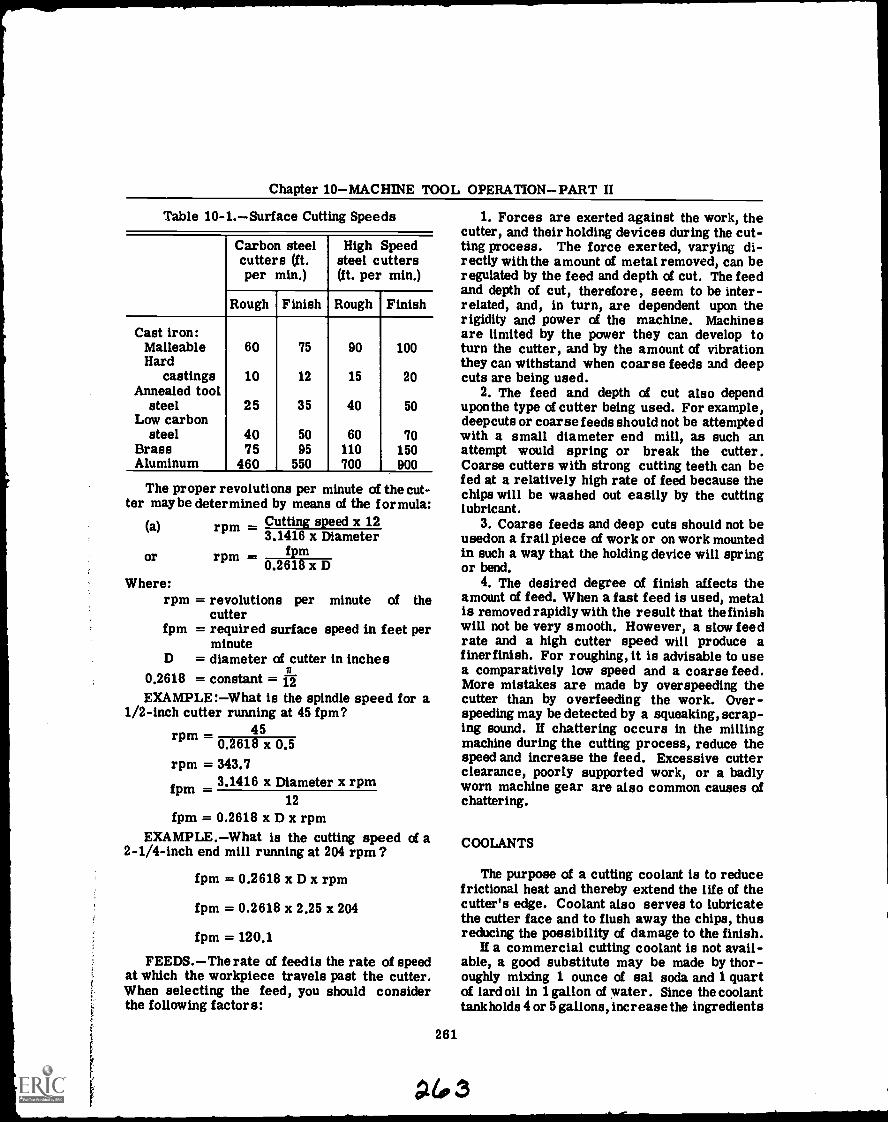
Chapter 10MACHINE TOOL OPERATIONPART II
Table 10-1.Surface Cutting Speeds
Carbon steelcutters (ft.per min.)
High Speedsteel cutters(ft. per min.)
Rough Finish Rough Finish
Cast iron:Malleable 60 75 90 100Hard
castings 10 12 15 20Annealed tool
steel 25 35 40 50Low carbon
steel 40 50 60 70Brass 75 95 110 150Aluminum 460 550 700 900
The proper revolutions per minute of the cut-ter maybe determined by means of the formula:
(a) rpm Cutting speed x 123.1416 x Diameter
fpmor rpm0.2618 x D
Where:rpm = revolutions per minute of the
cutterfpm = required surface speed in feet per
minuteD = diameter of cutter in inches
0.2618 = constant =EXAMPLE :What is the spindle speed for a
1/2-inch cutter running at 45 fpm?45rpm
0.2618 x 0,5rpm = 343.7
fpm 3.1416 x Diameter x rpm12
fpm = 0.2618 x D x rpmEXAMPLE.What is the cutting speed of a
2-1/4-inch end mill running at 204 rpm ?
fpm = 0.2618 x D x rpm
fpm = 0.2618 x 2.25 x 204
fpm = 120.1
FEEDS.The rate of feed is the rate of speedat which the workpiece travels past the cutter.When selecting the feed, you should considerthe following factors:
261
1. Forces are exerted against the work, thecutter, and their holding devices during the cut-ting process. The force exerted, varying di-rectly withthe amount of metal removed, can beregulated by the feed and depth of cut. The feedand depth of cut, therefore, seem to be inter-related, and, in turn, are dependent upon therigidity and power of the machine. Machinesare limited by the power they can develop toturn the cutter, and by the amount of vibrationthey can withstand when coarse feeds and deepcuts are being used.
2. The feed and depth of cut also dependuponthe type of cutter being used. For example,deep cuts or coarse feeds should not be attemptedwith a small diameter end mill, as such anattempt would spring or break the cutter.Coarse cutters with strong cutting teeth can befed at a relatively high rate of feed because thechips will be washed out easily by the cuttinglubricant.
3. Coarse feeds and deep cuts should not beusedon a frail piece of work or on work mountedin such a way that the holding device will springor bend.
4. The desired degree of finish affects theamount of feed. When a fast feed is used, metalis removed rapidly with the result that the finishwill not be very smooth. However, a slow feedrate and a high cutter speed will produce afiner finish. For roughing, it is advisable to usea comparatively low speed and a coarse feed.More mistakes are made by overspeeding thecutter than by overfeeding the work. Over-speeding may be detected by a squeaking, scrap-ing sound. If chattering occurs in the millingmachine during the cutting process, reduce thespeed and increase the feed. Excessive cutterclearance, poorly supported work, or a badlyworn machine gear are also common causes ofchattering.
COOLANTS
The purpose of a cutting coolant is to reducefrictional heat and thereby extend the life of thecutter's edge. Coolant also serves to lubricatethe cutter face and to flush away the chips, thusreducing the possibility of damage to the finish.
If a commercial cutting coolant is not avail-able, a good substitute may be made by thor-oughly mixing 1 ounce of sal soda and 1 quartof lard oil in 1 gallon of water. Since the coolanttank holds 4 or 5 gallons, increase the ingredients
Ato3
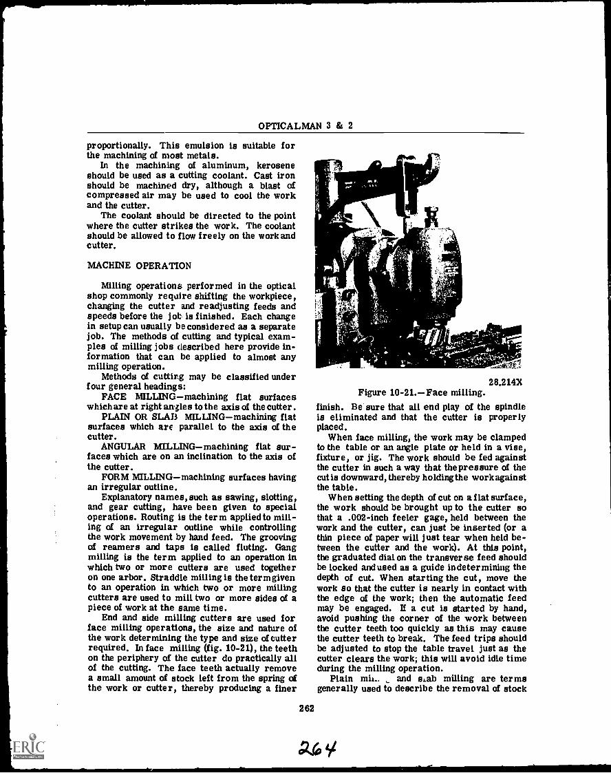
OPTICALMAN 3 & 2
proportionally. This emulsion is suitable forthe machining of most metals.
In the machining of aluminum, keroseneshould be used as a cutting coolant. Cast ironshould be machined dry, although a blast ofcompressed air may be used to cool the workand the cutter.
The coolant should be directed to the pointwhere the cutter strikes the work. The coolantshould be allowed to flow freely on the work andcutter.
MACHINE OPERATION
Milling operations performed in the opticalshop commonly require shifting the workpiece,changing the cutter and readjusting feeds andspeeds before the job is finished. Each changein setup can usually be considered as a separatejob. The methods of cutting and typical exam-ples of milling jobs described here provide in-formation that can be applied to almost anymilling operation.
Methods of cutting may be classified underfour general headings:
FACE MILLINGmachining flat surfaceswhich are at right angles to the axis of the cutter.
PLAIN OR SLAB MILLINGmachining flatsurfaces which are parallel to the axis of thecutter.
ANGULAR MILLINGmachining flat sur-faces which are on an inclination to the axis ofthe cutter.
FORM MILLINGmachining surfaces havingan irregular outline.
Explanatory names, such as sawing, slotting,and gear cutting, have been given to specialoperations. Routing is the term applied to mill-ing of an irregular outline while controllingthe work movement by hand feed. The groovingof reamers and taps is called fluting. Gangmilling is the term applied to an operation inwhich two or more cutters are used togetheron one arbor. Straddle milling is the term givento an operation in which two or more millingcutters are used to mill two or more sides of apiece of work at the same time.
End and side milling cutters are used forface milling operations, the size and nature ofthe work determining the type and size of cutterrequired. In face milling (fig. 10-21), the teethon the periphery of the cutter do practically allof the cutting. The face teeth actually removea small amount of stock left from the spring ofthe work or cutter, thereby producing a finer
28.214XFigure 10-21.Face milling.
finish. Be sure that all end play of the spindleis eliminated and that the cutter is properlyplaced.
When face milling, the work may be clampedto the table or an angle plate or held in a vise,fixture, or jig. The work should be fed againstthe cutter in such a way that the pressure of thecut is downward, thereby holding the work againstthe table.
When setting the depth of cut on a flat surface,the work should be brought up to the cutter sothat a .002-inch feeler gage, held between thework and the cutter, can just be inserted (or athin piece of paper will just tear when held be-tween the cutter and the work). At this point,the graduated dial on the transverse feed shouldbe locked and used as a guide in determining thedepth of cut. When starting the cut, move thework so that the cutter is nearly in contact withthe edge of the work; then the automatic feedmay be engaged. If a cut is started by hand,avoid pushing the corner of the work betweenthe cutter teeth too quickly as this may causethe cutter teeth to break. The feed trips shouldbe adjusted to stop the table travel just as thecutter clears the work; this will avoid idle timeduring the milling operation.
Plain mit.. and s,ab milling are termsgenerally used to describe the removal of stock
262
A6,
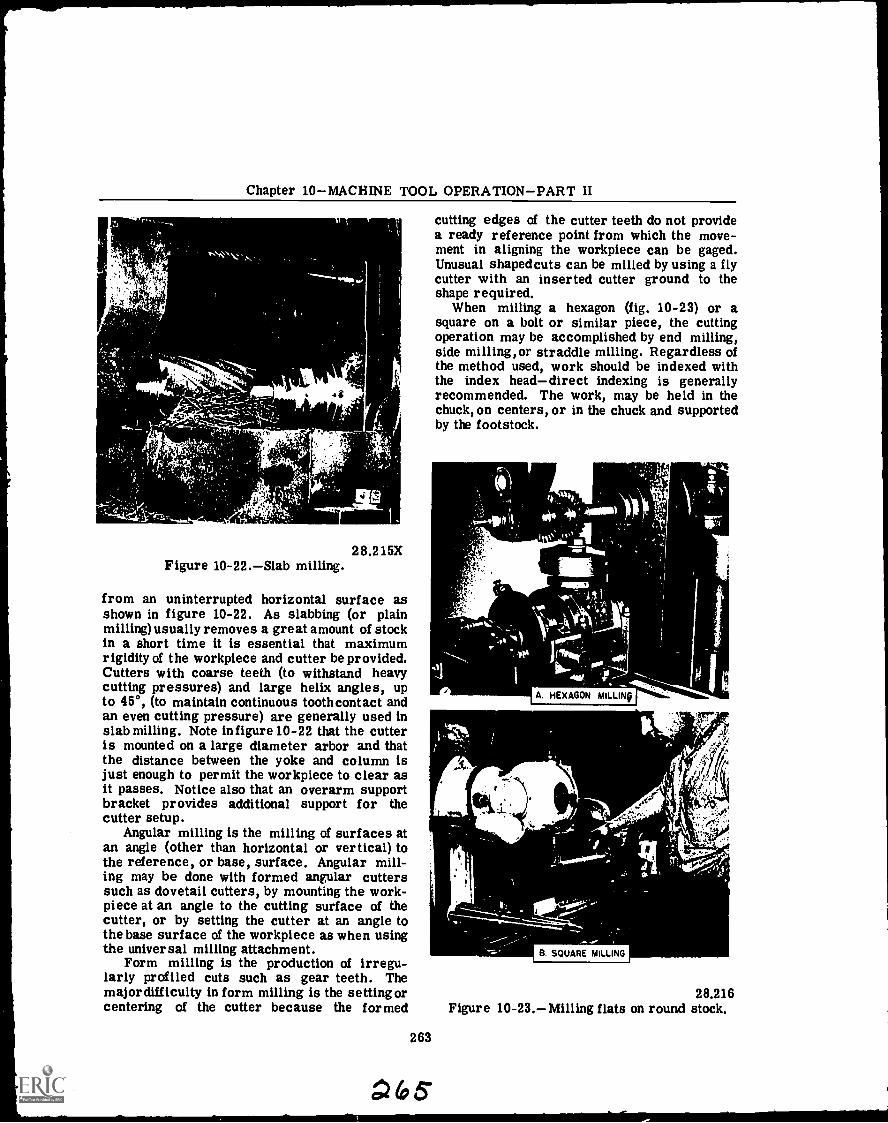
Chapter 10MACHINE TOOL OPERATIONPART II
4S
41
Figure 10-22.Slab milling.28.215X
from an uninterrupted horizontal surface asshown in figure 10-22. As slabbing (or plainmilling) usually removes a great amount of stockin a short time it is essential that maximumrigidity of the workpiece and cutter be provided.Cutters with coarse teeth (to withstand heavycutting pressures) and large helix angles, upto 45°, (to maintain continuous tooth contact and A HEXAGON MILLINO
an even cutting pressure) are generally used inslab milling. Note in figure 10-22 that the cutteris mounted on a large diameter arbor and thatthe distance between the yoke and column isjust enough to permit the workpiece to clear asit passes. Notice also that an overarm support galbracket provides additional support for the 15.1cutter setup.
Angular milling is the milling of surfaces atan angle (other than horizontal or vertical) to
4the reference, or base, surface. Angular mill-ing may be done with formed angular cutterssuch as dovetail cutters, by mounting the work-piece at an angle to the cutting surface of thecutter, or by setting the cutter at an angle tothe base surface of the workpiece as when usingthe universal milling attachment. B SQUARE MILLING
Form milling is the production of irregu-larly profiled cuts such as gear teeth. Themajor difficulty in form milling is the setting or 28.216centering of the cutter because the formed Figure 10-23.Milling flats on round stock.
cutting edges of the cutter teeth do not providea ready reference point from which the move-ment in aligning the workpiece can be gaged.Unusual shaped cuts can be milled by using a flycutter with an inserted cutter ground to theshape required.
When milling a hexagon (fig. 10-23) or asquare on a bolt or similar piece, the cuttingoperation may be accomplished by end milling,side milling,or straddle milling. Regardless ofthe method used, work should be indexed withthe index headdirect indexing is generallyrecommended. The work, may be held in thechuck, on centers, or in the chuck and supportedby the footstock.
. r
263
G;t5"
OPTICALMAN 3 & 2
When side milling or straddle milling, thework is usually held in the chuck. For endmilling, the work may be held in the chuck, oncenters, or in the chuck and supported by thefootstock.
Long work, such as a reamer that is to besquared, may be mounted between centers orheld in the chuck and supported on the outer endby the footstock center. The cutter used shouldbe an end mill and the work should be fed verti-cally. During this operation, the clamp providedat the front of the table should be brought intoposition to prevent longitudinal movement.
Where the number of pieces to be machinedwarrants the additional setup time required,the work may be held in a vertical position andstraddle milled. A pair of side milling cutters,which are of like diameter and of such a sizethat the space collar placed between them willclear the work, should be used. In adjustingthe milling cutters for the proper width ofhexagon or square, spacers are used to obtainthe required spacing of the cutters. The workshould be held in the chuck which in turn isfastened to the index head. The spindle of theindex head may then be adjusted to the re-quired vertical position. When the work is heldin the chuck, be careful to align the work sothat all sides of the hexagon or square will bemilled to the same length. As two sides of thework are finished at a cut, a square is com-pleted with two cuts and a hexagon with three cuts.
Side and end milling cutters are used to cuthexagons and squares except in the productionof a number of like parts as just described.When the side or end milling cutter is used,work is generally held in a chuck fastened tothe index head. The spindle of the index headmay be adjusted to either the vertical or hori-zontal position. The vertical position is pre-ferred, since the work is more easily observedand handled. To eliminate looseninof the chuckwhen only one cutter is used, the feed should beso arranged that it will operate in a directionthat will tend to tighten the chuck thread.
Usually, an opticalman will be able to get therepair parts you need from the supply depart-ment of your ship. On occasions however, thismay not be true and it is necessary to manu-facture spur gears or other parts. The follow-ing discussion on gear nomenclature, and gearmanufacture by utilization of spur gear formu-las, will assist you in your tasks. You mustbear in mind that only through application ofthis information and good experience will you be
264
able to satisfactorily manufacture gears thatwill work properly.
The two most important things pertaining tothe manufacture of a gear are: (1) calculatinggear dimensions, and (2) selecting the propercutter for machining the gear teeth.
In order for you to calculate dimensions of agear, you need to know the terms used to desig-nate the parts of a gear. The brief discussionwhich follows provides this information.
Refer to illustration 10-24 for terms usedin referring to or describing gears and gearteeth. The symbols in parentheses are stand-ard gear nomenclature symbols.
1. Outside diameter (D0) is the overall diam-eter of a gear.
2. Pitch diameter (D) represents the diam-eter of a circle used to calculate the dimen-sions of a gear. This pitch diameter is lessthan the outside diameter by an amount equalto twice the addendum.
3. Diametral pitch (P) is a ratio or numberof teeth per inch of pitch diameter.
4. Circular pitch (Cp) represents the lengthof an arc of the pitch circle measured from apoint on one tooth to a corresponding point onthe next tooth. There are as many circularpitches (of equal length) in a gear as there areteeth in that gear.
5. Addendum (a) is the height of a tooth abovethe pitch circle along a radial line.
6. Dedendum (b) is the depth of a tooth belowthe pitch circle along a radial line.
7. Whole depth of tooth (H) represents thetotal depth of a tooth groove. It consists ofone addendum plus (+) one dedendum.
8. Root diameter (DR) is the outside diam-eter less TWICE the whole depth.
9. Although not shown in the illustration,center distance (C) is the distance between theaxes of a pair of gears correctly meshed.
10. Chordal addendum (ac) represents thedistance (measured on a radial line) from thetop of a gear tooth to a chord subtending theintersections of the tooth - thickness arc and thesides of the tooth. Chordal tooth thickness (tc)represents the length of a chord subtended bythe circular-tooth-thickness arc.
Several methods have been devised for check-ing the accuracy of gear teeth, one of which ischecking the thickness of a gear tooth on astraight line through the points at which thepitch circle touches the gear tooth. This is themeasurement of CHORDAL THICKNESS.
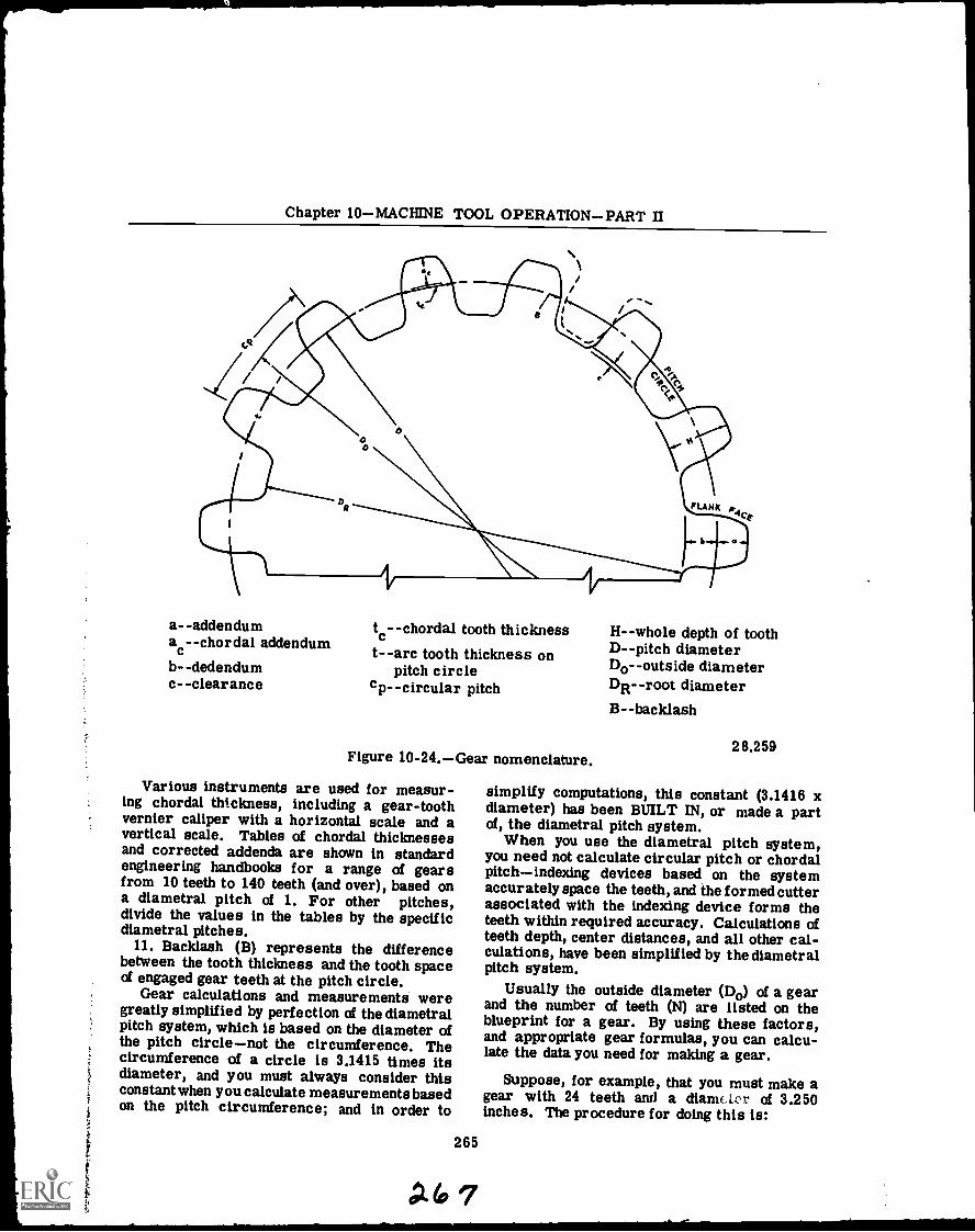
Chapter 10MACHINE TOOL OPERATIONPART II
a--addenduma c--chordal addendum
b--dedendumc--clearance
tc- -chordal tooth thicknesst- -arc tooth thickness on
pitch circlecpcircular pitch
Figure 10-24.Gear nomenclature.
Various instruments are used for measur-ing chordal thickness, including a gear-toothvernier caliper with a horizontal scale and avertical scale. Tables of chordal thicknessesand corrected addenda are shown in standardengineering handbooks for a range of gearsfrom 10 teeth to 140 teeth (and over), based ona diametral pitch of 1. For other pitches,divide the values in the tables by the specificdiametral pitches.
11. Backlash (B) represents the differencebetween the tooth thickness and the tooth spaceof engaged gear teeth at the pitch circle.
Gear calculations and measurements weregreatly simplified by perfection of the diametralpitch system, which is based on the diameter ofthe pitch circlenot the circumference. Thecircumference of a circle is 3.1415 times itsdiameter, and you must always consider thisconstant when you calculate measurementsbasedon the pitch circumference; and in order to
265
P.(07
H--whole depth of toothD--pitch diameterDooutside diameterDR--root diameterB--backlash
28.259
simplify computations, this constant (3.1416 xdiameter) has been BUILT IN, or made a partof, the diametral pitch system.
When you use the diametral pitch system,you need not calculate circular pitch or chordalpitchindexing devices based on the systemaccurately space the teeth, and the formed cutterassociated with the indexing device forms theteeth within required accuracy. Calculations ofteeth depth, center distances, and all other cal-culations, have been simplified by the diametralpitch system.
Usually the outside diameter (D0) of a gearand the number of teeth (N) are listed on theblueprint for a gear. By using these factors,and appropriate gear formulas, you can calcu-late the data you need for making a gear.
Suppose, for example, that you must make agear with 24 teeth and a diame ter of 3.250inches. The procedure for doing this is:
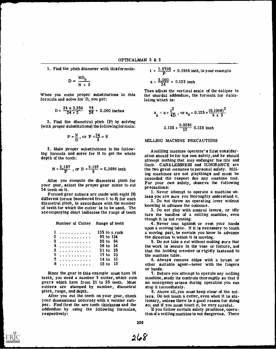
OPTICALMAN 3 & 2
1. Find the pitch diameter with thisformula:
ND,D= -
N + 2
When you make proper substitutions in thisformula and solve for D, you get:
24 x 3.250 78D = -6- = 3.000 inches24 +2
2. Find the diametral pitch (P) by solving(with proper substitutions) the followingformula:
P = ND
or P= L .83
3. Make proper substitutions in the follow-ing formula and solve for H to get the wholedepth of the tooth:
_1H = 2.15'
7 or H - 2.8 57 0.2696 inchP
After you compute the diametral pitch foryour gear, select the proper gear cutter to cut24 teeth on it.
Formed gear cutters are made with eight (8)different forms (numbered from 1 to 8) for eachdiametral pitch, in accordance with the numberof teeth for which the cutter is to be used. Theaccompanying chart indicates the range of teeth
Number of Cutter Range of teeth
1 135 to a rack2 55 to 1343 35 to 544 26 to 345 21 to 256 17 to 207 14 to 168 12 to 13
Since the gear in this example must have 24teeth, you need a number 5 cutter, which cutsgears which have from 21 to 25 teeth. Mostcutters are stamped by number, diametralpitch, range, and depth.
After you cut the teeth on your gear, checkyour dimensional accuracy with a vernier cali-per. Find first the arc tooth thickness and theaddendum by using the following formulas,respectively:
t 1.5708 0.1964 inch, in your example
3 00 0a = 0.125 inch4
Then adjust the vertical scale of the caliper tothe chordal addendum, the formula for calcu-lating which is:
ac r a+ t711-3 , or at = 0.125 (04
x.19643 )2
0.02860.125 +
0.020.128 inch
2
MILLING MACHINE PRECAUTIONS
A milling machine operator's first consider-ation should befor his own safety, and he shouldattempt nothing that may endanger his life andlimb. CARELESSNESS and IGNORANCE arethe two great menaces to personal safety. Mill-ing machines are not playthings and must beaccorded the respect due any machine tool.For your own safety, observe the followingprecautions:
1. Never attempt to operate a machine un-less you are sure you thoroughly understand it.
2. Do not throw an operating lever withoutknowing in advance the outcome.
3. Do not play with control levers, or idlyturn the handles of a milling machine, eventhough it is not running.
4. Never lean against or rest your handsupon a moving table. If it is necessary to toucha moving part, be certain you know in advancethe direction in which it is moving.
5. Do not take a cut without making sure thatthe work is secure in the vise or fixture, andthat the holding member is rigidly fastened tothe machine table.
6. Always remove chips with a brush orother suitable agentnever with the fingersor hands.
7. Before you attempt to operate any millingmachine, study its controls thoroughly so that ifan emergency arises during operation you canstop it immediately.
8. Above all, you must keep clear of the cut-ters. Do not touch a cutter, even when it is sta-tionary, unless there is a good reason for doingso; and if you must touch it, be very careful.
If you follow certain safety practices, opera-tion of a milling machine is not dangerous. There
266
to k
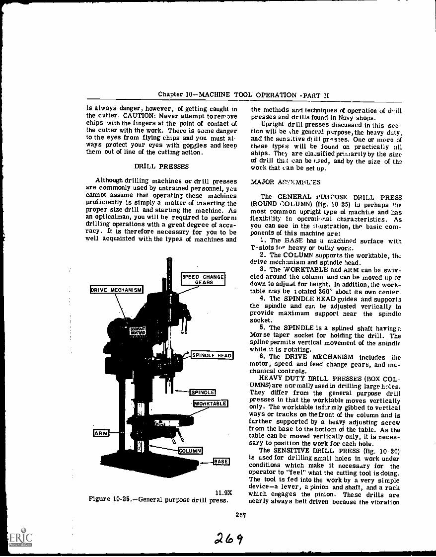
Chapter 10MACHINE TOOL OPERATION -PART II
is always danger, however, of getting caught inthe cutter. CAUTION: Never attempt toreirvechips with the fingers at the point of contact ofthe cutter with the work. There is some dangerto the eyes from flying chips and you must al-ways protect your eyes with goggles and keepthem out of line of the cutting action.
DRILL PRESSES
Although drilling machines or drill pressesare commonly used by untrained personnel, youcannot assume that operating these machinesproficiently is simply a matter of inserting theproper size drill and starting the machine. Asan opticalman, you will be required to performdrilling operations with a great degree of accu-racy. It is therefore necessary for you to bewell acquainted with the types of machines and
!DRIVE MECHANISM'
SPEED CHANGE'GEARS
SPINDLE HEAD
SPINDLE'
WORKTABITI
11.9XFigure 10-25.General purpose drill press.
267
the methods and techniques of operation of illpresses and drills found in Navy shops.
Upright drill presses discussed in this sec-tion will be the general purpose, the heavy duty,and the sensitive d! ill presses. One or more ofthese types will be found on practically allships. 'rho are classified priwarily by the sizeof drill thz.t can be r..sed, and by the size of thework that can be set up.
MAJOR AS`-'-7, MI4L.'ES
The GENERAL PURPOSE DRILL PRESS(ROUND COLUMN) (fig. 10-25) is perhaps *hemost common upright type of machii.e and hasflexitiity in operati,-nal characteristics. Asyou can see in the iliustration, the basic com-ponents of this machine are:
1. The BASE has a machined surface withT-slots filr heavy or bulky wortr.
2. The COLUMN supports the worktable, thedrive mechanism and spindle head.
3. The WORKTABLE and ARM can be swiv-eled around the column and can be moved up ordown to adjust for height. In addition,the work-table may be z otated 360' about its own center.
4. The SPINDLE HEAD guides and support3the spindle and can be adjusted vertically toprovide maximum support near the spindlesocket.
5. The SPINDLE is a splined shaft havingaMorse taper socket for holding the drill. Thespline permits vertical movement of the soindlewhile it is rotating.
6. The DRIVE MECHANISM includes themotor, speed and feed change gears, and me-chanical controls.
HEAVY DUTY DRILL PRESSES (BOX COL-UMNS) are normally used in drilling large h totes.They differ from the general purpose drillpresses in that the worktable moves verticallyonly. The worktable isfirmly gibbed to verticalways or tracks on thefront of the column and isfurther supported by a heavy adjusting screwfrom the base to the bottom of the table. As thetable can be moved vertically only, it is neces-sary to position the work for each hole.
The SENSITIVE DRILL PRESS (fig. 10-26)is used for drilling small holes in work underconditions which make it necessary for theoperator to "feel" what the cutting tool is doing.The tool is fed into the work by a very simpledevicea lever, a pinion and shaft, and a rackwhich engages the pinion. These drills arenearly always belt driven because the vibration
AO.
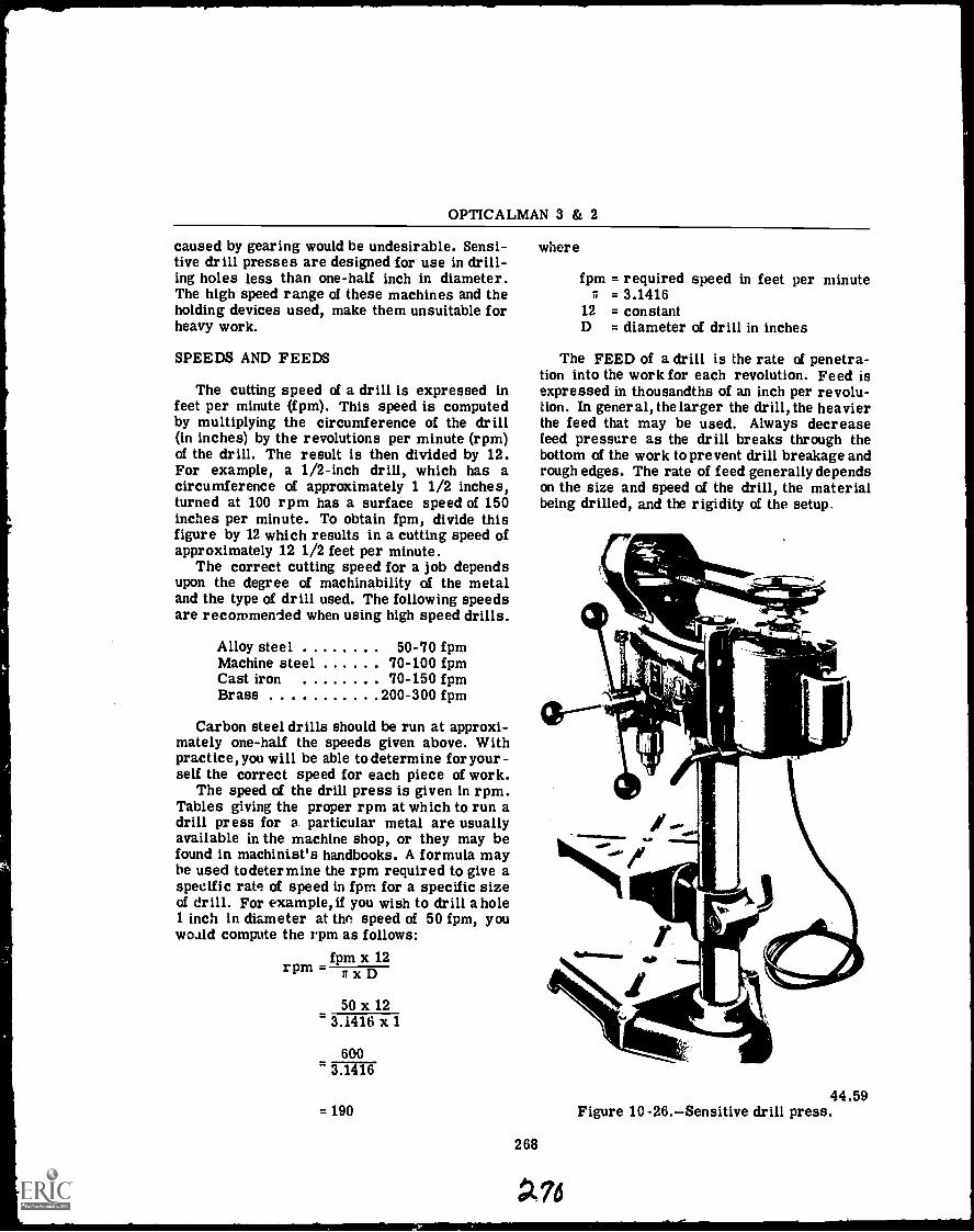
OPTICALMAN 3 & 2
caused by gearing would be undesirable. Sensi-tive drill presses are designed for use in drill-ing holes less than one-half inch in diameter.The high speed range of these machines and theholding devices used, make them unsuitable forheavy work.
SPEEDS AND FEEDS
The cutting speed of a drill is expressed infeet per minute (f pm). This speed is computedby multiplying the circumference of the drill(in inches) by the revolutions per minute (rpm)of the drill. The result is then divided by 12.For example, a 1/2-inch drill, which has acircumference of approximately 1 1/2 inches,turned at 100 rpm has a surface speed of 150inches per minute. To obtain fpm, divide thisfigure by 12 which results in a cutting speed ofapproximately 12 1/2 feet per minute.
The correct cutting speed for a job dependsupon the degree of machinability of the metaland the type of drill used. The following speedsare recommended when using high speed drills.
Alloy steelMachine steelCast ironBrass
50-70 fpm70-100 fpm70-150 fpm
200-300 fpm
Carbon steel drills should be run at approxi-mately one-half the speeds given above. Withpractice, you will be able to determine for your-self the correct speed for each piece of work.
The speed of the drill press is given in rpm.Tables giving the proper rpm at which to run adrill press for a particular metal are usuallyavailable in the machine shop, or they may befound in machinist's handbooks. A formula maybe used todetermine the rpm required to give aspecific rate of speed in fpm for a specific sizeof drill. For example, if you wish to drill a hole1 inch in diameter at the speed of 50 fpm, youwould compute the rpm as follows:
fpm x 12rpm= nxD
50 x 123.1416 x 1
6003.1416
where
fpm = required speed in feet per minute= 3 . 14 1 6
12 = constantD = diameter of drill in inches
The FEED of a drill is the rate of penetra-tion into the work for each revolution. Feed isexpressed in thousandths of an inch per revolu-tion. In general, the larger the drill, the heavierthe feed that may be used. Always decreasefeed pressure as the drill breaks through thebottom of the work to prevent drill breakage andrough edges. The rate of feed generally dependson the size and speed of the drill, the materialbeing drilled, and the rigidity of the setup.
44.59= 190 Figure 10 -26. Sensitive drill press.
268
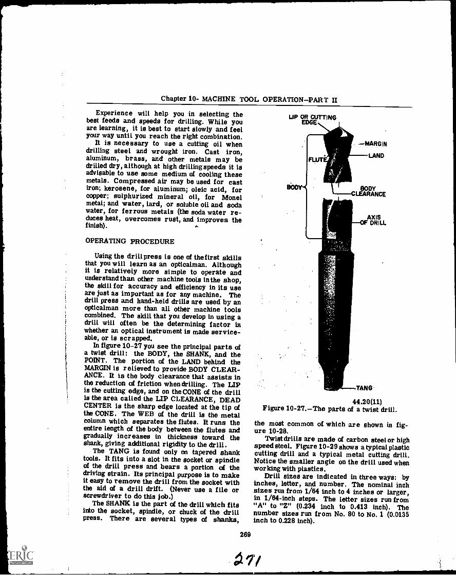
Chapter 10- MACHINE TOOL OPERATION PART II
Experience will help you in selecting thebest feeds and speeds for drilling. While youare learning, it is best to start slowly and feelyour way until you reach the right combination.
It is necessary to use a cutting oil whendrilling steel and wrought iron. Cast iron,aluminum, brass, and other metals may bedrilled dry, although at high drilling speeds it isadvisable to use some medium of cooling thesemetals. Compressed air may be used for castiron; kerosene, for aluminum; oleic acid, forcopper; sulphurized mineral oil, for Monelmetal; and water, lard, or soluble oil and sodawater, for ferrous metals (the soda water re-duces heat, overcomes rust, and improves thefinish).
OPERATING PROCEDURE
Using the drill press is one of the first skillsthat you will learn as an opticalman. Althoughit is relatively more simple to operate andunderstand than other machine tools in the shop,the skill for accuracy and efficiency in its useare just as important as for any machine. Thedrill press and hand-held drills are used by anopticalman more than all other machine toolscombined. The skill that you develop in using adrill will often be the determining factor inwhether an optical instrument is made service-able, or is scrapped.
In figure 10-27 you see the principal parts ofa twist drill: the BODY, the SHANK, and thePOINT. The portion of the LAND behind theMARGIN is relieved to provide BODY CLEAR-ANCE. It is the body clearance that assists inthe reduction of friction when drilling. The LIPis the cutting edge, and on the CONE of the drillis the area called the LIP CLEARANCE, DEADCENTER is the sharp edge located at the tip ofthe CONE, The WEB of the drill is the metalcolumn which separates the flutes. It runs theentire length of the body between the flutes andgradually increases in thickness toward theshank, giving additional rigidity to the drill.
The TANG is found only on tapered shanktools. It fits into a slot in the socket or spindleof the drill press and bears a portion of thedriving strain. Its principal purpose is to makeit easy to remove the drill from the socket withthe aid of a drill drift. (Never use a file orscrewdriver to do this job.)
The SHANK is the part of the drill which fitsinto the socket, spindle, or chuck of the drillpress. There are several types of shanks,
269
UP OR CUTTINGEDGE
MARGIN
LAND
BODYCLEARANCE
AXISOF DRILL
TANG
44.20(11)Figure 10-27.The parts of a twist drill.
the most common of which are shown in fig-ure 10-28.
Twist drills are made of carbon steelor highspeed steel. Figure 10-29 shows a typical plasticcutting drill and a typical metal cutting drill.Notice the smaller angle on the drill used whenworking with plastics.
Drill sizes are indicated in three ways: byinches, letter, and number. The nominal inchsizes run from 1/64 inch to 4 inches or larger,in 1/64-inch steps. The letter sizes run from"A" to "Z" (0.234 inch to 0.413 inch). Thenumber sizes run from No. 80 to No. 1 (0.0135inch to 0.228 inch).
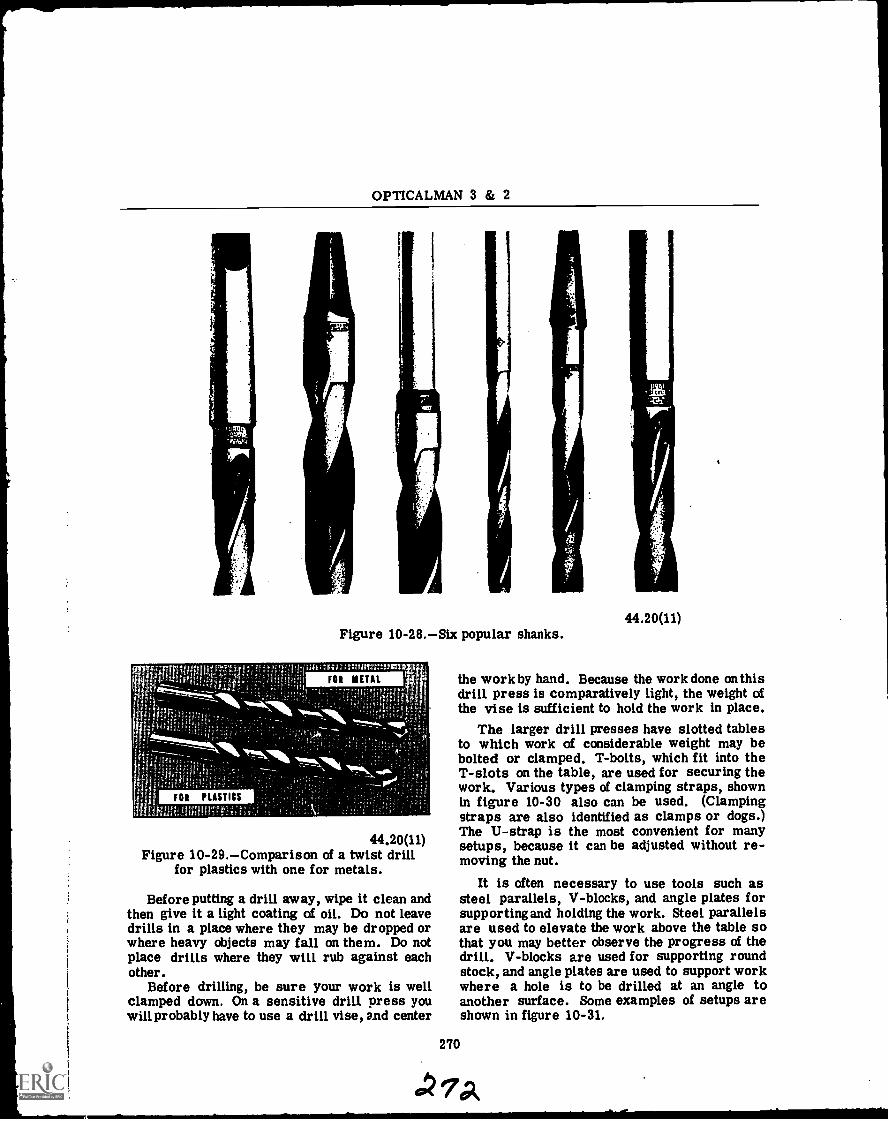
OPTICALMAN 3 & 2
FOR PLASTICS
.
Figure 10-28.Six popular shanks.
FOR METAL
44.20(11)Figure 10-29.Comparison of a twist drill
for plastics with one for metals.
Before putting a drill away, wipe it clean andthen give it a light coating of oil. Do not leavedrills in a place where they may be dropped orwhere heavy objects may fall on them. Do notplace drills where they will rub against eachother.
Before drilling, be sure your work is wellclamped down. On a sensitive drill press youwill probably have to use a drill vise, and center
44.20(11)
the workby hand. Because the work done on thisdrill press is comparatively light, the weight ofthe vise is sufficient to hold the work in place.
The larger drill presses have slotted tablesto which work of considerable weight may bebolted or clamped. T-bolts, which fit into theT-slots on the table, are used for securing thework. Various types of clamping straps, shownin figure 10-30 also can be used. (Clampingstraps are also identified as clamps or dogs.)The U-strap is the most convenient for manysetups, because it can be adjusted without re-moving the nut.
It is often necessary to use tools such assteel parallels, V-blocks, and angle plates forsupporting and holding the work. Steel parallelsare used to elevate the work above the table sothat you may better observe the progress of thedrill. V-blocks are used for supporting roundstock, and angle plates are used to support workwhere a hole is to be drilled at an angle toanother surface. Some examples of setups areshown in figure 10-31.
270
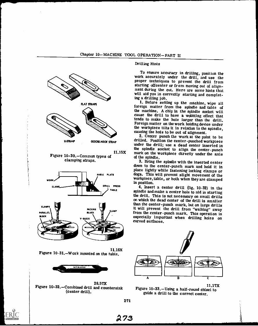
Chapter 10MACHINE TOOL OPERATIONPART II
FLAT STRAPS
U-STRAP GOOSE-NECK STRAP
Figure 10-30.Common types ofclamping straps.
WORK
11.15X
ANGLE PLATE
CLAMP DR ILL PRESS
TABLE
PACKING
BLOCKCLAMP
V- BLOCK
11.16XFigure 10-31.Work mounted on the table.
Drilling Hints
To ensure accuracy in drilling, position thework accurately under the drill, and use theproper techniques to prevent the drill fromstarting offcenter or from moving out of align-ment during the cut. Here are some hints thatwill aid you in correctly starting and complet-ing a drilling job.
1. Before setting up the machine, wipe allforeign matter from the spindle and table ofthe machine. A chip in the spindle socket willcause the drill to have a wobbling effect thattends to make the hole larger than the drill.Foreign matter on the work holding device underthe workpiece tilts it in relation to the spindle,causing the hole to be out of alignment.
2. Center punch the work at the point to bedrilled. Position the center-punched workpieceunder the drill; use a dead center inserted inthe spindle socket to align the center-punchmark on the workpiece directly under the axisof the spindle.
3. Bring the spindle with the inserted centerdown to the center-punch mark and hold it inplace lightly while fastening locking clamps ordogs. This will prevent slight movement of theworkpiece, table, or both when they are clampedin position.
4. Insert a center drill (fig. 10-32) in thespindle and make a center hole to aid in startingthe drill. This is not necessary on small drillson which the dead center of the drill is smallerthan the center-punch mark, but on large drillsit will prevent the drill from "walking" awayfrom the center-punch mark. This operation isespecially important when drilling holes oncurved surfaces.
28.57X 11.17XFigure 10-32.Combined drill and countersink Figure 10-33.Using a half-round chisel to(center drill). guide a drill to the correct center.
271
A73
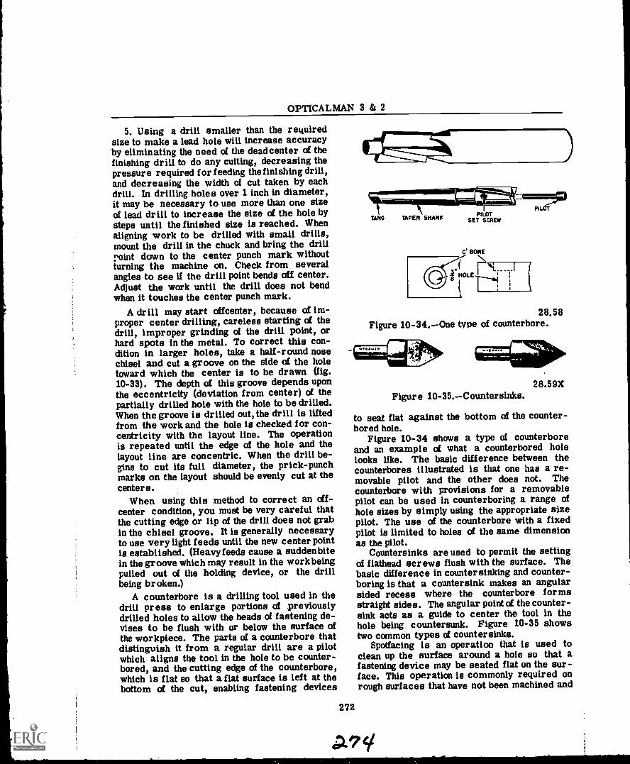
OPTICALMAN 3 & 2
5. Using a drill smaller than the requiredsize to make a lead hole will increase accuracyby eliminating the need of the dead center of thefinishing drill to do any cutting, decreasing thepressure required for feeding the finishing drill,and decreasing the width of cut taken by eachdrill. In drilling holes over 1 inch in diameter,it may be necessary to use more than one sizeof lead drill to increase the size of the hole bysteps until the finished size is reached. Whenaligning work to be drilled with small drills,mount the drill in the chuck and bring the drillroint down to the center punch mark withoutturning the machine on. Check from severalangles to see if the drill point bends off center.Adjust the work until the drill does not bendwhen it touches the center punch mark.
A drill may start offcenter, because of im-proper center drilling, careless starting of thedrill, improper grinding of the drill point, orhard spots in the metal. To correct this con-dition in larger holes, take a half-round nosechisel and cut a groove on the side of the holetoward which the center is to be drawn (fig.10-33). The depth of this groove depends uponthe eccentricity (deviation from center) of thepartially drilled hole with the hole to be drilled.When the groove is drilled out, the drill is liftedfrom the work and the hole is checked for con-centricity with the layout line. The operationis repeated until the edge of the hole and thelayout line are concentric. When the drill be-gins to cut its full diameter, the prick-punchmarks on the layout should be evenly cut at thecenters.
When using this method to correct an off-center condition, you must be very careful thatthe cutting edge or lip of the drill does not grabin the chisel groove. It is generally necessaryto use very light feeds until the new center pointis established. (Heavyfeeds cause a sudden bitein the groove which may result in the workbeingpulled out of the holding device, or the drillbeing broken.)
A counterbore is a drilling tool used in thedrill press to enlarge portions of previouslydrilled holes to allow the heads of fastening de-vises to be flush with or below the surface ofthe workpiece. The parts of a counterbore thatdistinguish it from a regular drill are a pilotwhich aligns the tool in the hole to be counter-bored, and the cutting edge of the counterbore,which is flat so that a flat surface is left at thebottom of the cut, enabling fastening devices
28.58Figure 10-34.One type of counterbore.
272
28.59XFigure 10-35.Countersinks.
to seat flat against the bottom of the counter-bored hole.
Figure 10-34 shows a type of counterboreand an example of what a counterbored holelooks like. The basic difference between thecounterbores illustrated is that one has a re-movable pilot and the other does not. Thecounterbore with provisions for a removablepilot can be used in counterboring a range ofhole sizes by simply using the appropriate sizepilot. The use of the counterbore with a fixedpilot is limited to holes of the same dimensionas the pilot.
Countersinks are used to permit the settingof flathead screws flush with the surface. Thebasic difference in countersinking and counter-boring is that a countersink makes an angularsided recess where the counterbore formsstraight sides. The angular point of the counter-sink acts as a guide to center the tool in thehole being countersunk. Figure 10-35 showstwo common types of countersinks.
Spotfacing is an operation that is used toclean up the surface around a hole so that afastening device may be seated flat on the sur-face. This operation is commonly required onrough surfaces that have not been machined and
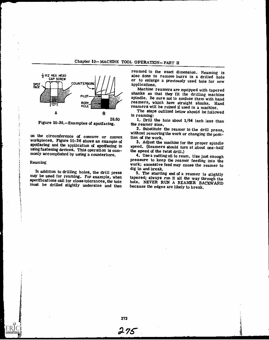
Chapter 10MACHINE TOOL OPERATIONPART II
z X2 HEX. HEADCAP SCREW
COUNTERBORE
A
PILOT
BODYHOLE
B
28.60Figure 10-36.Examples of spotfacing.
on the circumference of concave or convexworkpieces. Figure 10-36 shows an example ofspotfacing and the application of spotfacing inusing fastening devices. This operation is com-monly accomplished by using a counterbore.
Reaming
In addition to drilling holes, the drill pressmay be used for reaming. For example, whenspecifications call for close tolerances, the holemust be drilled slightly undersize and then
273
reamed to the exact dimension. Reaming isalso done to remove burrs in a drilled holeor to enlarge a previously used hole for newapplications.
Machine reamers are equipped with taperedshanks so that they fit the drilling machinespindle. Be sure not to confuse them with handreamers, which have straight shanks. Handreamers will be ruined U used in a machine.
The steps outlined below should be followedin reaming:
1. Drill the hole about 1/64 inch less thanthe reamer size.
2. Substitute the reamer in the drill press,without removing the work or changing the posi-tion of the work.
3. Adjust the machine for the proper spindlespeed. (Reamers should turn at about one-halfthe speed of the twist drill.)
4. Use a cutting oil to ream. Use just enoughpressure to keep the reamer feeding into thework; excessive feed may cause the reamer todig in and break.
5. The starting end of a reamer is slightlytapered; always run it all the way through thehole. NEVER RUN A REAMER BACKWARDbecause the edges are likely to break.
A76"
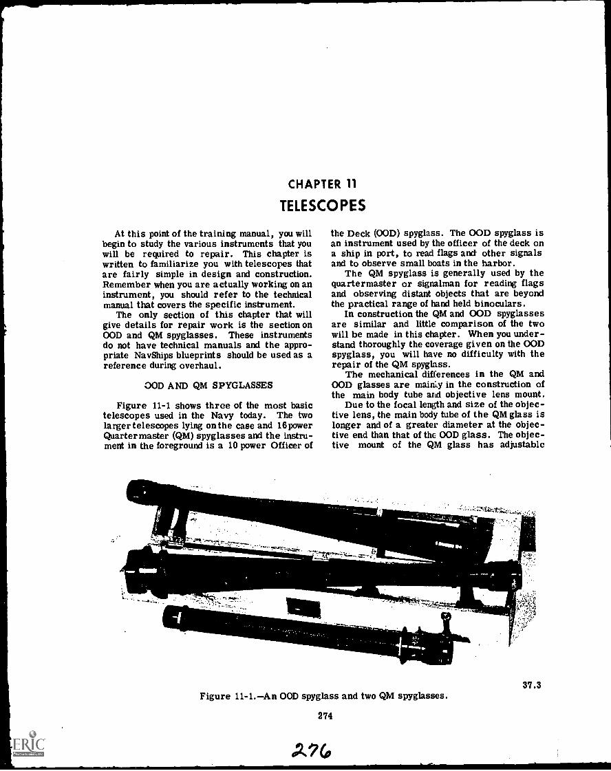
CHAPTER 11
TELESCOPES
At this point of the training manual, you willbegin to study the various instruments that youwill be required to repair. This chapter iswritten to familiarize you with telescopes thatare fairly simple in design and construction.Remember when you are actually working on aninstrument, you should refer to the technicalmanual that covers the specific instrument.
The only section of this chapter that willgive details for repair work is the section onOOD and QM spyglasses. These instrumentsdo not have technical manuals and the appro-priate Nav Ships blueprints should be used as areference during overhaul.
OOD AND QM SPYGLASSES
Figure 11-1 shows three of the most basictelescopes used in the Navy today. The twolarger telescopes lying on the case and 16powerQuartermaster (QM) spyglasses and the instru-ment in the foreground is a 10 power Officer of
"le
MIt
the Deck (OOD) spyglass. The OOD spyglass isan instrument used by the officer of the deck ona ship in port, to read flags and other signalsand to observe small boats in the harbor.
The QM spyglass is generally used by thequartermaster or signalman for reading flagsand observing distant objects that are beyondthe practical range of hand held binoculars.
In construction the QM and OOD spyglassesare similar and little comparison of the twowill be made in this chapter. When you under-stand thoroughly the coverage given on the OODspyglass, you will have no difficulty with therepair of the QM spyglass.
The mechanical differences in the QM andOOD glasses are mairi.y in the construction ofthe main body tube and objective lens mount.
Due to the focal length and size of the objec-tive lens, the main body tube of the QM glass islonger and of a greater diameter at the objec-tive end than that of the OOD glass. The objec-tive mount of the QM glass has adjustable
Figure 11-1.An OOD spyglass and two QM spyglasses.
274
-
37.3
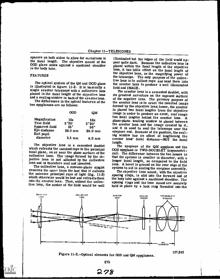
Chapter 11TELESCOPES
spacers on both sides to allow for variations inthe focal length. The objective mount of theOOD glass seats against a machined shoulderin the body tube.
FEATURES
The optical system of the QM and OOD glassis illustrated in figure 11-2. It is basically asingle erector telescope with a collective lensplaced in the focal length of the objective lensand a sealing window in back of the erector lens.
The differences in the optical features of thetwo spyglasses are as follows:
Magnification
OOD
10x
QM
16xTrue field 5°30' 3 °30'Apparent field 55° 56°Eye distance 29.0 mm 28.0 mmExit pupil
diameter 3.5 mm 4.0 mm
The objective lens is a cemented doubletwhich refracts the incident rays to the principalfocal plane, on or near the piano surface of thecollective lens. The image formed by the ob-jective lens is not affected by the collectivelens and is therefore real and inverted.
The collective lens, a convexo-plano singletreceives its nam^ from the fact that it collectsthe extreme principal rays of light (fig. 11-2)which otherwise would be lost and refracts theminto the, erector lens. Thus, without the collec-tive lens, the center of the field would be well
OBJECTIVEL ENS
COLLECTIVEL ENS
illuminated but the edges of the field would ap-pear quite dark. Because the collective lens isplaced within the focal length of the objectivelens, it has little effect on the focal length ofthe objective lens, or the magnifying power ofthe telescope. The only purpose of the collec-tive lens is to collect rays and send them intothe erector lens to produce a well illuminatedfield and IMAGE.
The erector lens is a cemented doublet, withits greatest curvature on the exposed surfaceof the negative lens. The primary purpose ofthe erector lens is to erect the inverted imageformed by the objective lens; hence, the erectoris placed two focal lengths from the objectiveimage in order to produce an erect, real imagetwo focal lengths behind the erector lens. Apiano -piano sealing window is placed betweenthe erector lens and the image created by it,and it is used to seal the telescope near theeyepiece end. Because of its position, the seal-ing window has an effect of lengthening theerector lens' focal distanceNOT the focallength.
The eyepiece of the QM spyglass and theOOD spyglass is TWO-DOUBLET (asymmetri-cal). The difference between the two lenses isthat the eyelens is smaller in diameter, with alonger focal length, as compared to the fieldlens. A bevel is ground on the rear edge of theeyelens to aid in sealing the eyepiece assembly.
The objective lens mount, with the objectivespacing rings, is slid into the forward end ofthe body tube against a machined shoulder. Thespacing rings and the lens mount are securelyheld in place by a lock ring threaded into the
ERECTORLENS
I OBJ
EX TENS/ON OP Rl -."-y
21 ERECTOR
Ow a
SEALINGWINDOW
A
21 ERECTOR
TwO.DOUBLETSEYEPIECE
Figure 11-2.Optical elements for OOD and QM spyglasses.
275
2 98
EF LIEVEPIECEI
137 .243
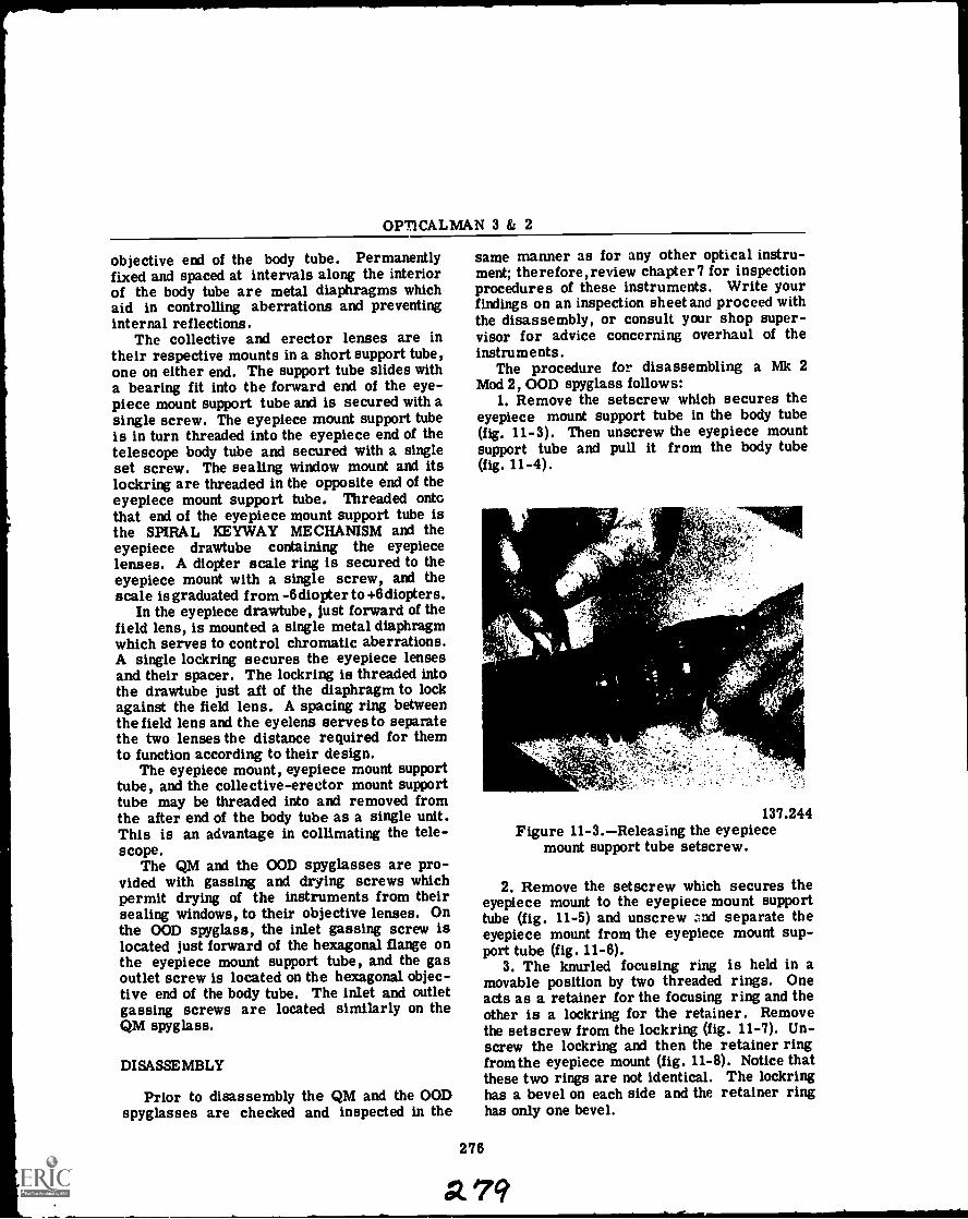
OPT1CALMAN 3 & 2
objective end of the body tube. Permanentlyfixed and spaced at intervals along the interiorof the body tube are metal diaphragms whichaid in controlling aberrations and preventinginternal reflections.
The collective and erector lenses are intheir respective mounts in a short support tube,one on either end. The support tube slides witha bearing fit into the forward end of the eye-piece mount support tube and is secured with asingle screw. The eyepiece mount support tubeis in turn threaded into the eyepiece end of thetelescope body tube and secured with a singleset screw. The sealing window mount and itslockring are threaded in the opposite end of theeyepiece mount support tube. Threaded ontothat end of the eyepiece mount support tube isthe SPIRAL KEYWAY MECHANISM and theeyepiece drawtube containing the eyepiecelenses. A diopter scale ring is secured to theeyepiece mount with a single screw, and thescale is graduated from -6 diopter to +6diopters.
In the eyepiece drawtube, just forward of thefield lens, is mounted a single metal diaphragmwhich serves to control chromatic aberrations.A single lockring secures the eyepiece lensesand their spacer. The lockring is threaded intothe drawtube just aft of the diaphragm to lockagainst the field lens. A spacing ring betweenthe field lens and the eyelens serves to separatethe two lenses the distance required for themto function according to their design.
The eyepiece mount, eyepiece mount supporttube, and the collective-erector mount supporttube may be threaded into and removed fromthe after end of the body tube as a single unit.This is an advantage in collimating the tele-scope.
The QM and the OOD spyglasses are pro-vided with gassing and drying screws whichpermit drying of the instruments from theirsealing windows, to their objective lenses. Onthe OOD spyglass, the inlet gassing screw islocated just forward of the hexagonal flange onthe eyepiece mount support tube, and the gasoutlet screw is located on the hexagonal objec-tive end of the body tube. The inlet and outletgassing screws are located similarly on theQM spyglass.
DISASSEMBLY
Prior to disassembly the QM and the OODspyglasses are checked and inspected in the
same manner as for any other optical instru-ment; therefore, review chapter? for inspectionprocedures of these instruments. Write yourfindings on an inspection sheet and proceed withthe disassembly, or consult your shop super-visor for advice concerning overhaul of theinstruments.
The procedure for disassembling a Mk 2Mod 2, OOD spyglass follows:
1. Remove the setscrew which secures theeyepiece mount support tube in the body tube(fig. 11-3). Then unscrew the eyepiece mountsupport tube and pull it from the body tube(fig. 11-4).
>':'(
%
a 4
137.244Figure 11-3.Releasing the eyepiece
mount support tube setscrew.
2. Remove the setscrew which secures theeyepiece mount to the eyepiece mount supporttube (fig. 11-5) and unscrew and separate theeyepiece mount from the eyepiece mount sup-port tube (fig. 11-6).
3. The knurled focusing ring is held in amovable position by two threaded rings. Oneacts as a retainer for the focusing ring and theother is a lockring for the retainer. Removethe setscrew from the lockring (fig. 11-7). Un-screw the lockring and then the retainer ringfrom the eyepiece mount (fig. 11-8). Notice thatthese two rings are not identical. The lockringhas a bevel on each side and the retainer ringhas only one bevel.
276
79
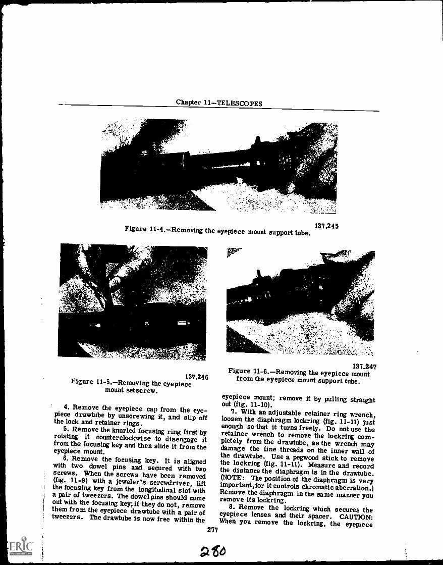
Chapter 11TELESCOPES
Ph'
r
Figure 11-4.Removing the eyepiece mount support tube.
YY4.4
t+
137.246Figure 11-5.Removing the eyepiece
mount setscrew.
4. Remove the eyepiece cap from the eye-piece drawtube by unscrewing it, and slip offthe lock and retainer rings.
5. Remove the knurled focusing ring first byrotating it counterclockwise to disengage itfrom the focusing key and then slide it from theeyepiece mount.
6. Remove the focusing key. It is alignedwith two dowel pins and secured with twoscrews. When the screws have been removed(fig. 11-9) with a jeweler's screwdriver, liftthe focusing key from the longitudinal slot witha pair of tweezers. The dowel pins should comeout with the focusing key; if they do not, removethem from the eyepiece drawtube with a pair oftweezers. The drawtube is now free within the
277
137.245
lerr
'14'1114yyy
-' .2;
--2, W. '
:4x1 ,k.---`-
er-;
137.247Figure 11-6.Removing the eyepiece mount
from the eyepiece mount support tube.
eyepiece mount; remove it by pulling straightout (fig. 11-10).
7. With an adjustable retainer ring wrench,loosen the diaphragm lockring (fig. 11-11) justenough so that it turns freely. Do not use theretainer wrench to remove the lockring com-pletely from the drawtube, as the wrench maydamage the fine threads on the inner wall ofthe drawtube. Use a pegwood stick to removethe lockring (fig. 11-11). Measure and recordthe distance the diaphragm is in the drawtube.(NOTE: The position of the diaphragm is veryimportant, for it controls chromatic aberration.)Remove the diaphragm in the same manner youremove its lockring.
8. Remove the lockring which secures theeyepiece lenses and their spacer. CAUTION:When you remove the lockring, the eyepiece
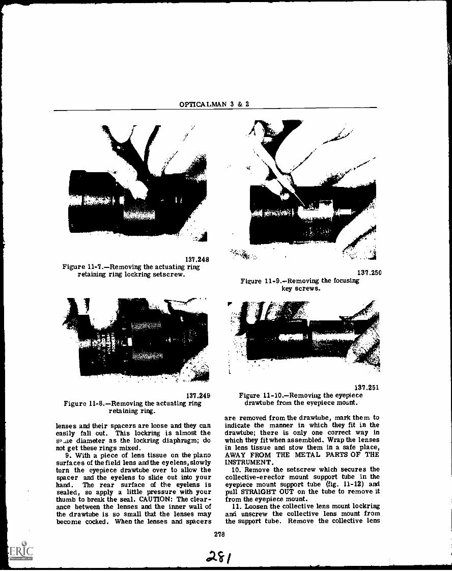
OPTICALMAN 3 & 2
___
137.248Figure 11-7.Removing the actuating ring
retaining ring lockring setscrew.
137.249Figure 11-8.Removing the actuating ring
retaining ring.
lenses and their spacers are loose and they caneasily fall out. This lockring is almost thes2 die diameter as the lockring diaphragm; donot get these rings mixed.
9. With a piece of lens tissue on the planosurfaces of the field lens and the eyelens, slowlyturn the eyepiece drawtube over to allow thespacer and the eyelens to slide out into yourhand. The rear surface of the eyelens issealed, so apply a little pressure with yourthumb to break the seal. CAUTION: The clear-ance between the lenses and the inner wall ofthe drawtube is so small that the lenses maybecome cocked. When the lenses and spacers
278
137.250Figure 11-9.Removing the focusing
key screws.
."
137.251Figure 11-10.Removing the eyepiece
drawtube from the eyepiece mount.
are removed from the drawtube, mark them toindicate the manner in which they fit in thedrawtube; there is only one correct way inwhich they fit when assembled. Wrap the lensesin lens tissue and stow them in a safe place,AWAY FROM THE METAL PARTS OF THEINSTRUMENT.
10.' Remove the setscrew which secures thecollective-erector mount support tube in theeyepiece mount support tube (fig. 11-12) andpull STRAIGHT OUT on the tube to remove itfrom the eyepiece mount.
11. Loosen the collective lens mount lockringand unscrew the collective lens mount fromthe support tube. Remove the collective lens
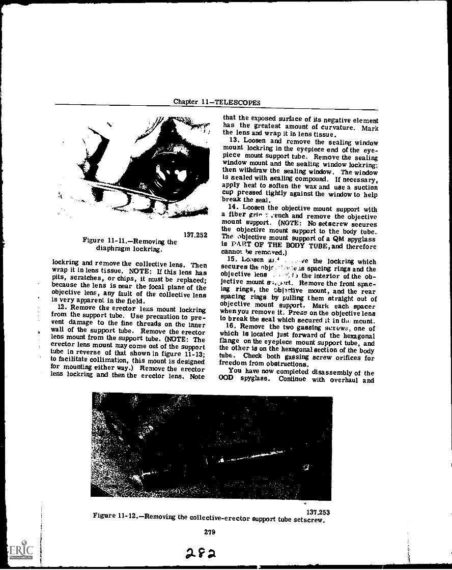
Chapter 11TELESCOPES
137.252Figure 11-11.Removing the
diaphragm lockring.
lockring and remove the collective lens. Thenwrap it in lens tissue. NOTE: If this lens haspits, scratches, or chips, it must be replaced;because the lens is near the focal plane of theobjective lens, any fault of the collective lensis very apparent in the field.
12. Remove the erector leas mount lockringfrom the support tube. Use precaution to pre-vent damage to the fine threads on the innerwall of the support tube. Remove the erectorlens mount from the support tube. (NOTE: Theerector lens mount may come out of the supporttube in reverse of that shown in figure 11-13;to facilitate collimation, this mount is designedfor mounting either way.) Remove the erectorlens lockring and then the erector lens. Note
that the exposed surface of its negative elementhas the greatest amount of curvature. Markthe lens and wrap it in lens tissue.
13. Loosen and remove the sealing windowmount lockring in the eyepiece end of the eye-piece mount support tube. Remove the sealingwindow mount and the sealing window lockring;then withdraw the sealing window. The windowis sealed with sealing compound. If necessary,apply heat to soften the wax and use a suctioncup pressed tightly against the window to helpbreak the seal.
14. Loosen the objective mount support witha fiber grit, tench and remove the objectivemount support. (NOTE: No setscrew securesthe objective mount support to the body tube.The objective mount support of a QM spyglassis PitRT OF THE BODY TUBE, and thereforecannot he removed.)
15. Loosen ay. . ve the lockring whichsecures tht nbj' . : .t- :e As spacing rings and theobjective lens . the interior of the ob-jective mount lit Remove the front spac-ing rings, the DbOrtive mount, and the rearspacing rings by pulling them straight out ofobjective mount support. Mark each spacerwhen you remove it. Press on the objective lensto break the seal which secured it in Mc. mount.
16. Remove the two gassing screws, one ofwhich is located just forward of the hexagonalflange on the eyepiece mount support tube, andthe other is on the hexagonal section of the bodytube. Check both gassing screw orifices forfreedom from obstructions.
You have now completed disassembly of theOOD spyglass. Continue with overhaul and
137.253Figure 11-12.Removing the collective-erector support tube setscrew.
279
Avg
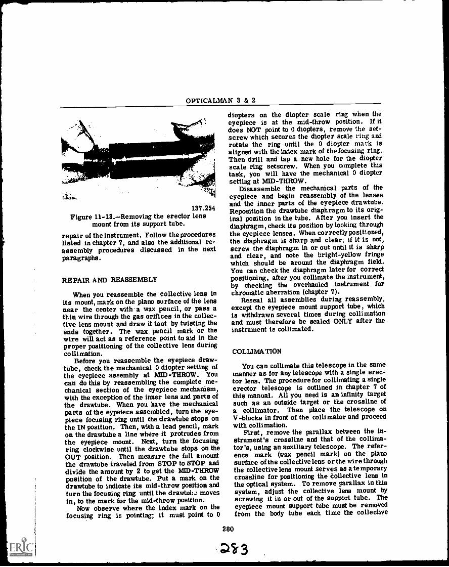
OPTICALMAN 3 & 2
diopters on the diopter scale ring when theeyepiece is at the mid-throw position. If it
Aalsilka
does NOT point to 0 diopters, remove the set-screw which secures the diopter scale ring androtate the ring until the 0 diopter mark isaligned with the index mark of the focusing ring.Then drill and tap a new hole for the diopterscale ring setscrew. When you complete thistask, you will have the mechanical 0 dioptersetting at MID-THROW.
-a.toDisassemble the mechanical parts of the
137.254Figure 11-13.Removing the erector lens
mount from its support tube.
repair of the instrument. Follow the procedureslisted in chapter 7, and also the additional re-assembly procedures discussed in the nextparagraphs.
REPAIR AND REASSEMBLY
When you reassemble the collective lens inits mount, mark on the piano surface of the lensnear the center with a wax pencil, or pass athin wire through the gas orifices in the collec-tive lens mount and draw it taut by twisting theends together. The wax. pencil mark or thewire will act as a reference point to aid in theproper positioning of the collective lens duringcollimation.
Before you reassemble the eyepiece draw-tube, check the mechanical 0 diopter setting ofthe eyepiece assembly at MID-THROW. Youcan do this by reassembling the complete me-chanical section of the eyepiece mechanism,with the exception of the inner lens and parts ofthe drawtube. When you have the mechanicalparts of the eypeiece assembled, turn the eye-piece focusing ring until the drawtube stops onthe IN position. Then, with a lead pencil, markon the drawtube a line where it protrudes fromthe eyepiece mount. Next, turn the focusingring clockwise until the drawtube stops on theOUT position. Then measure the full amountthe drawtube traveled from STOP to STOP anddivide the amount by 2 to get the MID-THROWposition of the drawtube. Put a mark on thedrawtube to indicate its mid-throw position andturn the focusing ring until the drawtubJ movesin, to the mark for the mid-throw position.
Now observe where the index mark on thefocusing ring is pointing; it must point to 0
eyepiece and begin reassembly of the lensesand the inner parts of the eyepiece drawtube.Reposition the drawtube diaphragm to its orig-inal position in the tube. After you insert thediaphragm, check its position by looking throughthe eyepiece lenses. When correctly positioned,the diaphragm is sharp and clear; if it is not,screw the diaphragm in or out until it is sharpand clear, and note the bright-yellow fringewhich should be around the diaphragm field.You can check the diaphragm later for correctpositioning, after you collimate the instrument,by checking the overhauled instrument forchromatic aberration (chapter 7).
Reseal all assemblies during reassembly,except the eyepiece mount support tube, whichis withdrawn several times during collimationand must therefore be sealed ONLY after theinstrument is collimated.
280
COLLIMATION
You can collimate this telescope in the samemanner as for any telescope with a single erec-tor lens. The procedure for collimating a singleerector telescope is outlined in chapter 7 ofthis manual. All you need is an infinity targetsuch as an outside target or the crossline ofa collimator. Then place the telescope onV-blocks in front of the collimator and proceedwith collimation.
First, remove the parallax between the in-strument's crossline and that of the collima-tor's, using an auxiliary telescope. The refer-ence mark (wax pencil mark) on the planosurface of the collective lens or the wire throughthe collective lens mount serves as a temporarycrossline for positioning the collective lens inthe optical system. To remove parallax in thissystem, adjust the collective lens mount byscrewing it in or out of the support tube. Theeyepiece mount support tube must be removedfrom the body tube each time the collective
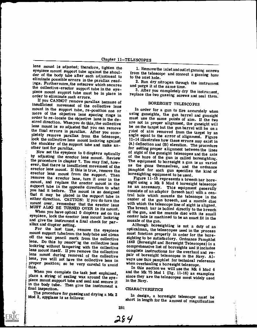
Chapter 11TELESCOPES
lens mount is adjusted; therefore, tighten theeyepiece mount support tube against the shoul-der of the body tube after each adjustment toeliminate possible errors in the parallax read-ings. Furthermore,the setscrew which securesthe collective-erector support tube in the eye-piece mount support tube must be in place inorder to eliminate such errors.
If you CANNOT remove parallax because ofinsufficient movement of the collective lensmount in the support tube, re-position one ormore of the objective lens spacing rings inorder to re-locate the objective lens in the de-sired direction. Whenyou do this,the collectivelens mount is so adjusted that you can removethe final errors in parallax. After you com-pletely remove parallax from the telescope,lock the collective lens mount lockring againstthe shoulder of the support tube and make an-other test for parallax.
Now set the eyepiece to 0 diopters opticallyby adjusting the erector lens mount. Reviewthe procedure in chapter 7. You may find, how-ever, that there is insufficient movement of theerector lens mount. If this is true, remove theerector lens mount from the support. Thenremove the erector lens, turn it over in themount, and replace the erector mount in thesupport tube in the opposite direction to whatyou had it before. The mount is so designedthat it may be placed in the support tube ineither direction. CAUTION: If you do turn themount over, remember that the erector lensMUST ALSO BE TURNED OVER in its mount.
When you have optical 0 diopters set on theeyepiece, lock the erector lens mount lockringand give the instrument a final check for par-allax and diopter setting.
For the last time, remove the eyepiecemount support tube from the body tube and cleanoff the wax pencil mark from the collectivelens. Do this by removing the collective lenslockring without tampering with the collectivelens mount itself. If you remove the collectivelens mount during removal of the collectivelens, you will not have the collective lens inproper position; so be very careful to avoidthis.
When you complete the task just explained,place a string of sealing wax around the eye-piece mount support tube and seal and secure itin the body tube. Then give the instrument afinal inspection.
The procedure for gassingand drying a Mk 2Mod 2, spyglass is as follows:
1. Remove the inlet and outlet gassing screwsfrom the telescope and connect a gassing hoseto the inlet hole.
2. Run dry nitrogen through the instrumentand purge it at the same time.
3. After you completely dry the instrument,replace the two gassing screws and seal them.
BORESIGHT TELESCOPESIn order for a gun to fire accurately when
using gunsights, the gun barrel and gunsightmust use the same points of aim. If the twoare not in proper alignment, the gunsight willbe on the target but the gun barrel will be on apoint of aim removed from the target by anangle equal to the error of alignment. Figure11-14 illustrates how these errors may exist in(A) deflection and (B) elevation. The procedurefor setting proper alignment between the linesof sight of the gunsight telescopes and the axisof the bore of the gun is called boresighting.The equipment to boresight a gun is as variedas the guns themselves, and the ordnancepamphlet for each gun specifies the kind ofboresighting equipment to be used.
Figure 11-15 represents a breech bar bore-sight using a Mk 8 Mod 6 boresight telescopeas an accessory. This equipment generallyconsists of an adaptor (breech bar) with a cen-tral hole which mounts the telescope in thecenter of the gun breech, and a muzzle discwith which the telescope line of sight is aligned.The breech bar is bolted directly to the breechof the gun, and the muzzle disc with its smallcenter hole is machined to be an exact fit in themuzzle of the gun.
Although boresighting is not a duty of anopticalman, the telescopes used in the processmust function properly in order for the bore-sighting to be satisfactory. Ordnance Pamphlet1449 (Boresight and Boresight Telescopes) is acomprehensive list of boresights and it includescomplete instructions for the overhaul and re-pair of boresight telescopes in the Navy. Al-ways use this pamphlet for technical referencewhen overhauling a boresight telescope.
In this section we will use the Mk 8 Mod 6and the Mk 75 Mod 1 (fig. 11-16) as examplessince they are the telescopes most widely usedin the Navy.
281
CHARACTERISTICS
In design, a boresight telescope must beshort in length for the amount of magnification
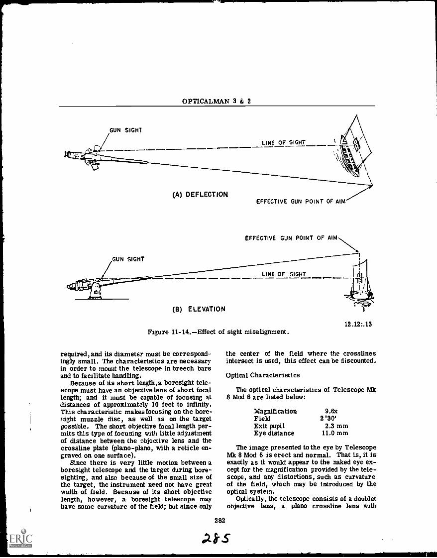
OPTICALMAN 3 & 2
GUN SIGHT
LINE OF SIGHT
(A) DEFLECTIONEFFECTIVE GUN POINT OF AIM
EFFECTIVE GUN POINT OF
LINE OF SIGHT
(B) ELEVATION
Figure 11-14.Effect of sight misalignment.
required, and its diameter must be correspond-ingly small. The characteristics are necessaryin order to mount the telescope in breech barsand to facilitate handling.
Because of its short length, a boresight tele-scope must have an objective lens of short focallength; and it must be capable of focusing atdistances of approximately 10 feet to infinity.This characteristic makes focusing on the bore-sight muzzle disc, as well as on the targetpossible. The short objective focal length per-mits this type of focusing with little adjustmentof distance between the objective lens and thecrossline plate (piano- piano, with a reticle en-graved on one surface).
Since there is very little motion between aboresight telescope and the target during bore-sighting, and also because of the small size ofthe target, the instrument need not have greatwidth of field. Because of its short objectivelength, however, a boresight telescope mayhave some curvature of the field; but since only
282
the center of the field where the crosslinesintersect is used, this effect can be discounted.
Optical Characteristics
The optical characteristics of Telescope Mk8 Mod 6 are listed below:
Magnification 9.6xField 2°30'Exit pupil 2.3 mmEye distance 11.0 mm
The image presented to the eye by TelescopeMk 8 Mod 6 is erect and normal. That is, it isexactly as it would appear to the naked eye ex-cept for the magnification provided by the tele-scope, and any distortions, such as curvatureof the field, which may be introduced by theoptical system.
Optically, the telescope consists of a doubletobjective lens, a piano crossline lens with
AS-S
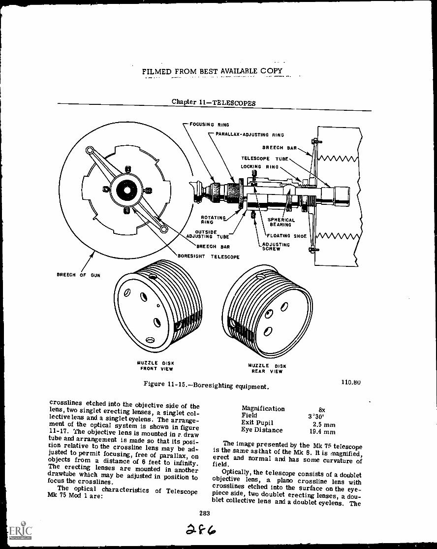
FILMED FROM BEST AVAILABLE COPY
Chapter 11TELESCOPES
FOCUSING RING
PARALLAX-ADJUSTING RING
BREECH BAR
TELESCOPE TUBE
LOCKING RING
iROTATINGRING
OUTSIDEADJUSTING TUBE
BREECH BAR
BORESIGHT TELESCOPE
SPHERICALBEARING
FLOATING SHOE
ADJUSTINGSCREW
BREECH OF GUN
MUZZLE DISKFRONT VIEW
MUZZLE DISKREAR VIEW
Figure 11-15.Boresighting equipment.
crosslines etched into the objective side of thelens, two singlet erecting lenses, a singlet col-lective lens and a singlet eyelens. The arrange-ment of the optical system is shown in figure11-17. The objective lens is mounted in 2. drawtube and arrangement is made so that its posi-tion relative to the crossline lens may be ad-justed to permit focusing, free of parallax, onobjects from a distance of 6 feet to infinity.The erecting lenses are mounted in anotherdrawtube which may be adjusted in position tofocus the crosslines.
The optical characteristics of TelescopeMk 75 Mod 1 are:
283
MagnificationFieldExit PupilEye Distance
8x3°30'
2.5 mm19.4 mm
110.80
The image presented by the Mk 75 telescopeis the same as that of the Mk 8. It is magnified,erect and normal and has some curvature offield.
Optically, the telescope consists of a doubletobjective lens, a piano crossline lens withcrosslines etched into the surface on the eye-piece side, two doublet erecting lenses, a dou-blet collective lens and a doublet eyelens. The
AH.
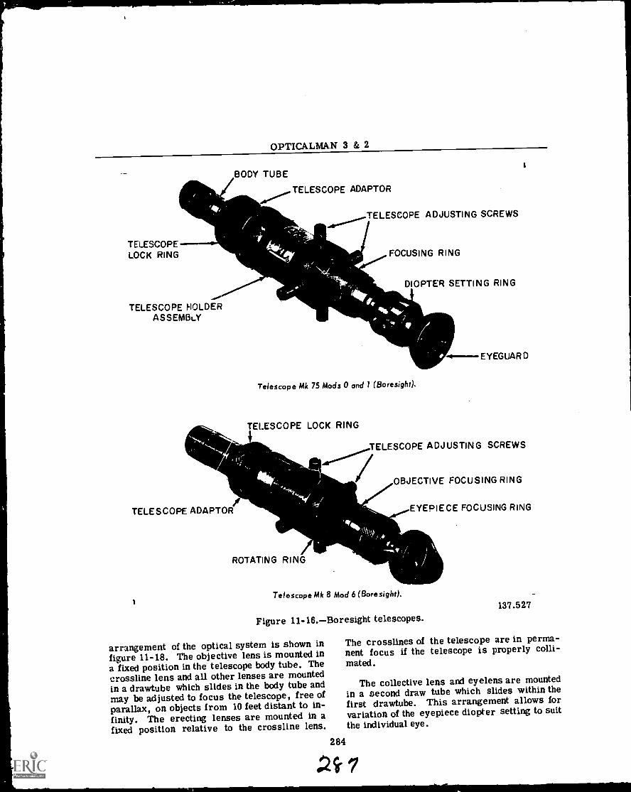
OPTICALMAN 3 & 2
BODY TUBE
TELESCOPELOCK RING
..,""TELESCOPE HOLDER
ASSEMBLY
TELESCOPE ADAPTOR
TELESCOPE ADJUSTING SCREWS
FOCUSING RING
DIOPTER SETTING RING
Telescope Mk 75 Mods 0 and 1 (Boresight).
TELESCOPE LOCK RING
I.
-4--EYEGUARD
TELESCOPE ADJUSTING SCREWS
OBJECTIVE FOCUSING RING
TELESCOPE ADAPTOR EYEPIECE FOCUSING RING
ROTATING RING
Telescope Mk 8 Mod 6 (Boresight).
Figure 11-16.Boresight telescopes.
arrangement of the optical system is shown infigure 11-18. The objective lens is mounted ina fixed position in the telescope body tube. Thecrossline lens and all other lenses are mountedin a drawtube which slides in the body tube andmay be adjusted to focus the telescope, free ofparallax, on objects from 10 feet distant to in-finity. The erecting lenses are mounted in afixed position relative to the crossline lens.
284
137.527
The crosslines of the telescope are in perma-nent focus if the telescope is properly colli-mated.
The collective lens and eyelens are mountedin a second draw tube which slides within thefirst drawtube. This arrangement allows forvariation of the eyepiece diopter setting to suitthe individual eye.
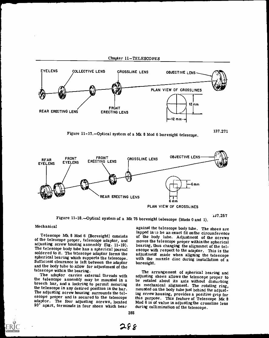
Chapter 11TELESCOPES
EYELENS COLLECTIVE LENS CROSSLINE LENS OBJECTIVE LENS
REAR ERECTING LENS
REAREYELENS
FRONTERECTING LENS
PLAN VIEW OF CROSSLINES
Figure 11-17.Optical system of a Mk 8 Mod 6 boresight telescope.
FRONTEYELENS
FRONTERECTING LENS
CROSSLINE LENS OBJECTIVE LENS
137.271
REAR ERECTING LENS
6mm
6 mm
PLAN VIEW OF CROSSLINES
137.257Figure 11-18.Optical system of a Mk 75 boresight telescope (Mods 0 and 1).
Mechanical
Telescope Mk 8 Mod 6 (Boresight) consistsof the telescope proper, telescope adaptor, andadjusting screw housing assembly (fig. 11-19).The telescope body tube has a spherical journalsoldered to it. The telescope adaptor forms thespherical bearing which supports the telescope.Sufficient clearance is left between the adaptorand the body tube to allow for adjustment of thetelescope within the bearing.
The adaptor carries external threads withthe telescope assembly may be mounted in abreech bar, and a lockring to permit securingthe telescope in any desired position in the bar.The adjusting screw housing surrounds the tel-escope proper and is secured to the telescopeadaptor. The four adjusting screws, located90° apart, terminate in four shoes which bear
against the telescope body tube. The shoes arelapped in La be an exact fit on the circumferenceof the body tube. Adjustment of the screwsmoves the telescope proper within the sphericalbearing, thus changing the alignmnet of the tel-escope with respect to the adaptor. This is theadjustment made when aligning the telescopewith the muzzle disc during installation of aboresight.
The arrangement of spherical bearing andadjusting shoes allows the telescope proper tobe rotated about its axis without disturbingits mechanical alignment. The rotating ring,mounted on the body tube just behind the adjust-ing screw housing, provides a positive grip forthis purpose. This feature of Telescope Mk 8Mod 6 is of value in adjusting the crossline lensduring collimination of the telescope.
285
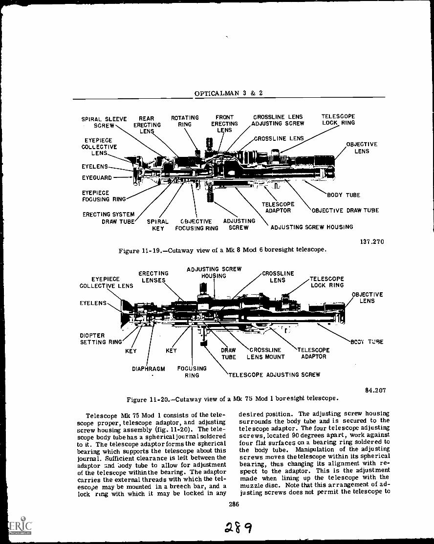
OPTICALMAN 3 & 2
SPIRAL SLEEVE REAR ROTATINGSCREW ERECTING RING
LENS
EYEPIECECOLLECTIVE
LENS
EYELENS
EYEGUARD
FRONTERECTING
LENS
CROSSLINE LENS TELESCOPEADJUSTING SCREW LOCK RING
CROSSLINE LENS
EYEPIECEFOCUSING RING
ERECTING SYSTEM
orb
DRAW TUBE SPIRAL CBJECTIVEKEY FOCUSING RING
ADJUSTINGSCREW ADJUSTING SCREW HOUSING
TELESCOPEADAPTOR OBJECTIVE DRAW TUBE
OBJECTIVELENS
BODY TUBE
Figure 11-19.Cutaway view of a Mk 8 Mod 6 boresight telescope.
ERECTINGEYEPIECE LENSES
COLLECTIVE LENS
EYELENS
DIOPTERSETTING RING
4
//KEY
DIAPHRAGM
KEY
ADJUSTING SCREWHOUSING
1
CROSSLINE7TELESCOPE
LOCK RING
FOCUSINGRING
137.270
B JLEECNTSI V E
DRAW CROSSLINE TELESCOPETUBE LENS MOUNT ADAPTOR
TELESCOPE ADJUSTING SCREW
Figure 11-20.Cutaway view of a Mk 75 Mod 1 boresight telescope.
Telescope Mk 75 Mod 1 consists of the tele-scope proper, telescope adaptor, and adjustingscrew housing assembly (fig. 11-20). The tele-scope body tube has a spherical journal solderedto it. The telescope adaptor forms the sphericalbearing which supports the telescope about thisjournal. Sufficient clearance is left between theadaptor :aid 'Jody tube to allow for adjustmentof the telescope within the bearing. The adaptorcarries the external threads with which the tel-escope may be mounted in a breech bar, and alock ring with which it may be locked in any
286
BCD'i TUBE
84.207
desired position. The adjusting screw housingsurrounds the body tube and is secured to thetelescope adaptor. The four telescope adjustingscrews, located 90 degrees apart, work againstfour flat surfaces on a bearing ring soldered tothe body tube. Manipulation of the adjustingscrews moves the telescope within its sphericalbearing, thus changing its alignment with re-spect to the adaptor. This is the adjustmentmade when lining up the telescope with themuzzle disc. Note that this arrangement of ad-justing screws does not permit the telescope to
(29

Chapter 11TELESCOPES
be rotated within the adaptor and housing as inTelescope Mk 8 Mod 6.
DISASSEMBLY
Ordnance Pamphlet, OP 1449, gives detailedprocedures for the disassembly, repair, andreassembly of boresight telescopes duringoverhaul in an optical repair shop. Along withthe instructions are complete exploded drawingsand parts lists for the telescopes under discus-sion. It is mandatory that a repairman use thisOP 1449 when performing repairs.
As a routine before disassembly, the repair-man should always:
Examine the telescope for any obviousdamage such as bent or broken tubes, damagedadjusting screws, broken lenses and faulty fo-cusing ring action. Note any such damage, forrepair or replacement bef ore reassembling.
Place the telescope in a boresight fixtureon a collimator table with the telescope adjust-ing screws in vertical and horizontal positions.Adjust the telescope so the crossline intersec-tion is superimposed on that of the collimator.Rotate the sight through 360 degrees stoppingat each 90 degree point to note the drift of thesight intersection from that of the collimator.If there is drift, the crossline lens positioningis incorrect.
Check the field for full field and sharpdefinition of the crosslines. If the field is notcompletely full and circular, one or more ofthe tubes may be bent or dented or a lens maybe out of position. If the definition of the tele-scope crosslines is not sharp and clear afterfocusing, the positioning of one or more of thelenses within the telescope is incorrect.
REPAIR AND REASSEMBLY
During the repair and reassembly of a bore-sight telescope always follow the proceduresthat are outlined in the appropriate technicalmanual and maintenance requirements that ap-ply to all optical instruments.
Some important items that apply specificallyto boresight telescopes are:
The body tube should be checked on a man-drel for straightness. If it is slightly bent ordented, it may be straightened on a lathe byspinning it between centers and forcing a man-drel through it. If there is a pronounced bendor dent in the tube it must be replaced.
287
cto
If you have removed burrs from the spher-ical bearing or the journal, it may be necessaryto lap in the bearing. Be thorough in yourcheck, as the telescope must be free to movesmoothly in the journal.
Check the fit of all draw tube systems forease and smoothness of operation, without anylateral play. If they do not meet requirements,lap them in and make any other repairs asneeded.
GUNSIGHT TELESCOPES
In this section,we will discuss and illustratetwo of the fixed prism Gunsight Telescopes usedin the Navy. They are the Mk 74 and Mk 79.These telescopes are used as examples of gun-sight telescopes because they are basic in de-sign and construction. The Mk 74 telescope(fig. 11-21) is a deviated line of sight telescopeand the Mk 70 (fig. 11-22) is an offset line ofsight telescope. Both telescopes are designedfor use on the sights of antiaircraft gun mounts.
;4 wti "r,
111110:._
5
137.272Figure 11-21.Two views of a Mk 74 telescope.
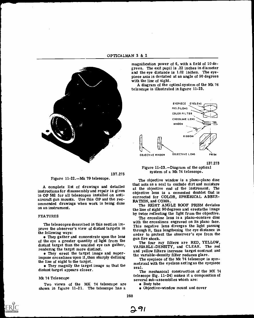
OPTICALMAN 3 & 2
137.275Figure 11-22.Mk 79 telescope.
A complete list of drawings and detailedinstructions for disassembly and repair is givenin OP 582 for all telescopes installed on anti-aircraft gun mounts. Use this OP and the rec-ommended drawings when work is being doneon an instrument.
FEATURES
The telescopes described in this section im-prove the observer's view of distant targets inthe following ways:
They gather and concentrate upon the lensof the eye a greater quantity of light from thedistant target than the unaided eye can gather,rendering the target more distinct.
They erect the target image and super-impose crosslines upon it,thus sharply definingthe line of sight to the target.
They magnify the target image so that thedistant target appears closer.
Mk 74 TelescopeTwo views of the MK 74 telescope are
shown in figure 11-21. The telescope has a
magnification power of 6, with a field of 10 de-grees. The exit pupil is .22 inches in diameterand the eye distance is 1.02 inches. The eye-piece axis is deviated at an angle of 90 degreeswith the line of sight.
A diagram of the optical system of the Mk 74telescope is illustrated in figure 11-23.
EYEPIECE EYELENS
FIELD L ENS
COLOR FILTER
CROSSLINE LENS
WINDOW
OBJECTIVE WINDOW
RIBBON
OBJECTIVE L ENS PRISM
137.273Figure 11-23.Diagram of the optical
system of a Mk 74 telescope.
The objective window is a plano-plano discthat acts as a seal to exclude dirt and moistureat the objective end of the instrument. Theobjective lens is a cemented doublet that iscorrected for COLOR, SPHERICAL ABBER-RATION, and COMA.
The RIGHT ANGLE ROOF PRISM deviatesthe line of sight 90degrees and erects the imageby twice reflecting the light from the objective.
The crossline lens is a piano- concave discwith the crosslines engraved on its plano face.This negative lens diverges the light passingthrough it, thus lengthening the eye distance inorder to protect the observer's eye from thegun fire shock.
The four ray filters are RED, YELLOW,VARIABLE-DENSITY, and CLEAR. The redand yellow filters increase target contrast andthe variable-density filter reduces glare.
The eyepiece of the Mk 74 telescope is sym-metrical with the eyelens acting as the eyepieceseal.
The mechanical construction of the MK 74telescope (fig. 11-24) makes it a composition ofseveral sub-assemblies which are:
Body tubeObjective-window mount and cover
288
QMI
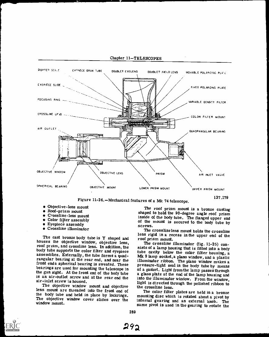
Chapter 11TELESCOPES
DIOPTER SCA,_E
EYEPIECE SLIDE
FOCUSING RING
CROSSLINE LF'4S
AIR CUTLET
EYEPIECE DRAW TUBE DOUBLET EYELENS DOUBLET FIELD LENS MOVABLE POLARIZING PLA':,.
FIXED POLARIZING PLATE
VARIABLE DENSITY FILTER
COLOR FILTER MOUNT
OUAORANGUL AR BEARING
OBJECTIVE WINOOW OBJECTIVE LENS
SPHERICAL BEARING
PRISM AIR INLET VALVE
OBJECTIVE MOUNT LOWER PRISM MOUNT
Figure 11-24.Mechanical features of a Mk 74 telescope.Objective-lens mountRoof-prism mountCrossline-lens mountColor filter assemblyEyepiece assemblyCrossline illuminator
The cast bronze body tube is Y shaped andhouses the objective window, objective lens,roof prism, and crossline lens. In addition, thebody tube supports the color filter and eyepieceassemblies. Externally, the tube forms a quad-rangular bearing at the rear end, and near thefront enda spherical bearing is sweated. Thesebearings are used for mounting the telescope inthe gun sight. At the front end of the body tubeis an air-outlet screw and at the rear end theair-inlet screw is housed.
The objective window mount and objectivelens mount are threaded into the front end ofthe body tube and held in place by lockrings.The objective window cover slides over thewindow mount.
289
UPPER PRISM MOUNT
137.179
The roof prism mount is a bronze castingshaped to hold the 90-degree angle roof prisminside of the body tube. The flanged upper endof the mount is secured to the body tube byscrews.
The crossline lens mount holds the crosslinelens rigid in a recess in the upper end of theroof prism mount.
The crossline illuminator (fig. 11-25) con-sists of a lamp housing that is fitted into a bodytube cavity below the color filter housing, aMk 9 lamp soc.ket,a plano window, and a plasticilluminator ribbon. The piano window makes apressure-tight seal in the body tube by meansof a gasket. Light from the lamp passes througha glass plate at the end of the lamp housing andinto the illuminator window. From the window,light is directed through the polished ribbon tothe crossline lens.
The color filter plates are held in a bronzemounting disc which is rotated about a pivot byinternal gearing and an external knob. Thesame pivot is used in the gearing to rotate the
P92
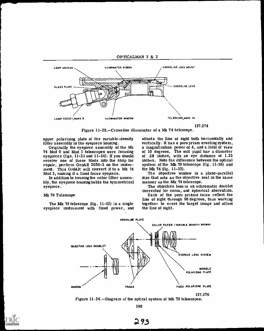
OPTICALMAN 3 & 2
LAMP HOUSING
GLASS PLATE
ILLUMINATOR RIBBON CROSSLINE LENS MOUNT
CROSSLINE LENS
/LAMP SOCKET,MARK 9 ILLUMINATOR WINDOW TEL ESGOPE,mARK 74
Figure 11-25.Crossline illuminator of a Mk 74 telescope.
upper polarizing plate of the variable-densityfilter assembly in the eyepiece housing.
Originally the eyepiece assembly of the Mk74 Mod 0 and Mod 1 telescopes were focusingeyepieces (figs. 11-21 and 11-24). If you shouldreceive one of these Mods into the shop forrepair, perform Ord Alt 2039-2 on the instru-ment. This Ord Alt will convert it to a Mk 74Mod 3, making it a fixed focus eyepiece.
In addition to housing the color filter assem-bly, the eyepiece housing holds the symmetricaleyepiece.
Mk 79 Telescope
The Mk 79 telescope (fig. 11-22) is a singleeyepiece instrument with fixed power, and
OBJECTIVE LENS DOUBLET
WINDOW
137.274
offsets the line of sight both horizontally andvertically. It has a poro prism erecting system,a magnification power of 4, and a field of viewof 10 degrees. The exit pupil has a diameterof .28 inches, with an eye distance of 1.33inches. Note the difference between the opticalsystem of the Mk 79 telescope (fig. 11-26) andthe Mk 74 (fig. 11-23).
The objective window is a plano-paralleldisc that acts as the objective seal in the samemanner as the Mk 74 telescope.
The objective lens is an achromatic doubletcorrected for coma, and spherical aberration.
Each of the poro prisms twice reflect theline of sight through 90 degrees, thus workingtogether to erect the target image and offsetthe line of sight.
CROSSLINE PLATE
COLOR FILTER ( VARIABLE DENSITY SHOWN)
EYEPICCE LENS SYSTEM
PRISMS
MOVABLE
POLARIZING PLATE
FIXED POLARIZING PLATE
137.276Figure 11-26.Diagram of the optical system of Mk 79 telescopes.
290
93
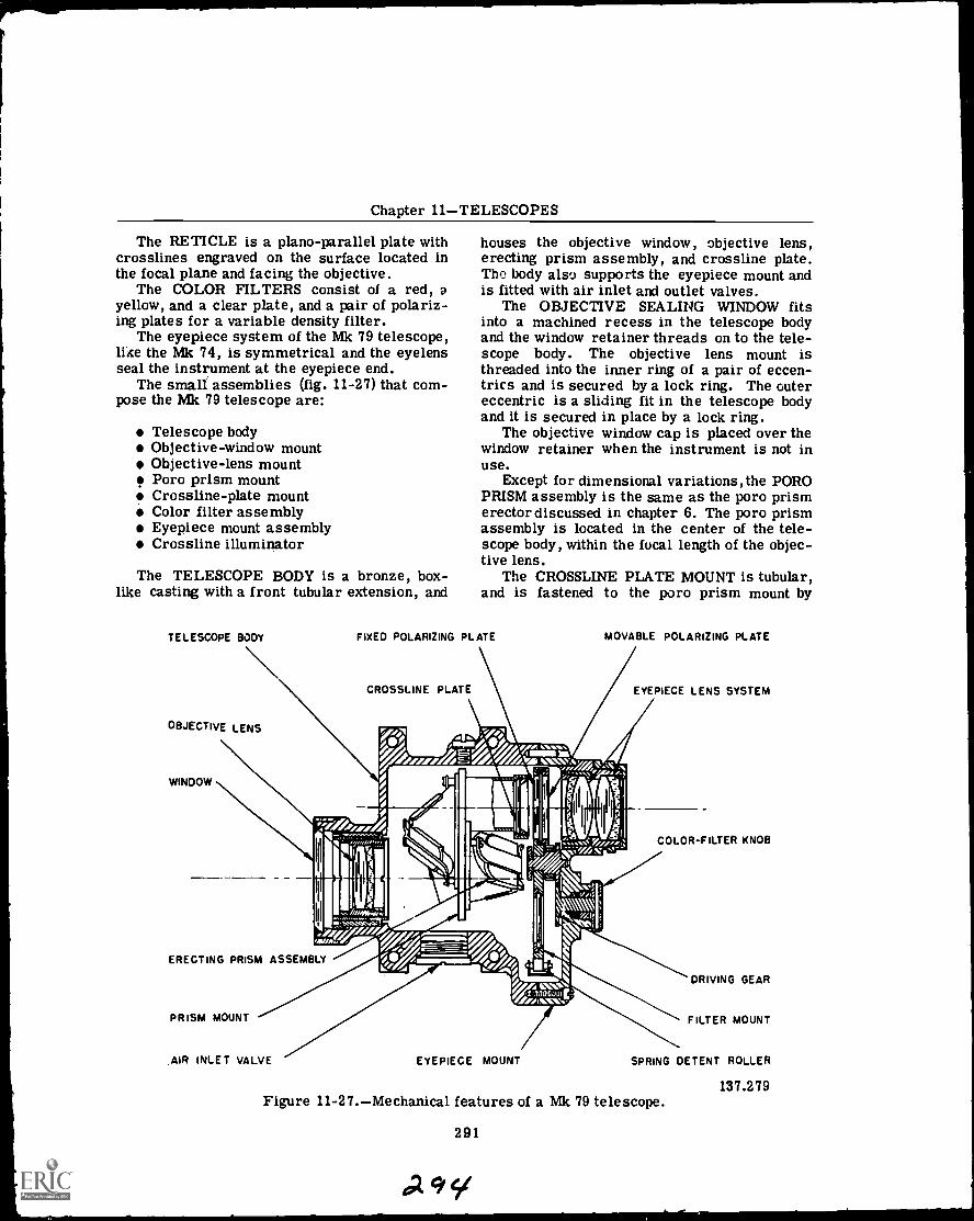
Chapter 11TELESCOPES
The RETICLE is a piano- parallel plate withcrosslines engraved on the surface located inthe focal plane and facing the objective.
The COLOR FILTERS consist of a red, ayellow, and a clear plate, and a pair of polariz-ing plates for a variable density filter.
The eyepiece system of the Mk 79 telescope,like the Mk 74, is symmetrical and the eyelensseal the instrument at the eyepiece end.
The small assemblies (fig. 11-27) that com-pose the Mk 79 telescope are:
Telescope bodyObjective-window mountObjective-lens mountPoro prism mountCross line-plate mountColor filter assemblyEyepiece mount assemblyCross line illuminator
The TELESCOPE BODY is a bronze, box-like casting with a front tubular extension, and
TELESCOPE BODY
OBJECTIVE LENS
houses the objective window, objective lens,erecting prism assembly, and crossline plate.The body also supports the eyepiece mount andis fitted with air inlet and outlet valves.
The OBJECTIVE SEALING WINDOW fitsinto a machined recess in the telescope bodyand the window retainer threads on to the tele-scope body. The objective lens mount isthreaded into the inner ring of a pair of eccen-trics and is secured by a lock ring. The outereccentric is a sliding fit in the telescope bodyand it is secured in place by a lock ring.
The objective window cap is placed over thewindow retainer when the instrument is not inuse.
Except for dimensional variations,the POROPRISM assembly is the same as the poro prismerector discussed in chapter 6. The poro prismassembly is located in the center of the tele-scope body, within the focal length of the objec-tive lens.
The CROSSLINE PLATE MOUNT is tubular,and is fastened to the poro prism mount by
FIXED POLARIZING PLATE
CROSSLINE PLATE
MOVABLE POLARIZING PLATE
EYEPIECE LENS SYSTEM
COLOR-FILTER KNOB
ERECTING PRISM ASSEMBLY
AIR INLET VALVE EYEPIECE MOUNT
DRIVING GEAR
FILTER MOUNT
SPRING DETENT ROLLER
137.279Figure 11-27.Mechanical features of a Mk 79 telescope.
291
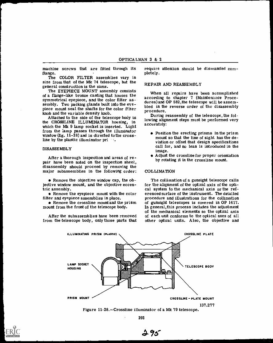
OPTICALMAN 3 & 2
machine screws that are fitted through itsflange.
The COLOR FILTER assemblies vary insize from that of the Mk 74 telescope, but thegeneral construction is the same.
The EYEPIECE MOUNT assembly consistsof a flange-like bronze casting that houses thesymmetrical eyepiece, and the color filter as-sembly. Two packing glands built into the eye-piece mount seal the shafts for the color filterknob and the variable density knob.
Attached to the side of the telescope body isthe CROSSLINE ILLUMINATOR housing, inwhich the Mk 9 lamp socket is inserted. Lightfrom the lamp passes through the illuminatorwindow (fig. 11-28) and is directed to the cross-line by the plastic illuminator pri .
DISASSEMBLY
After a thorough inspection and areas of re-pair have been noted on the inspection sheet,disassembly should proceed by removing themajor subassemblies in the following order:
Remove the objective window cap, the ob-jective window mount, and the objective eccen-tric assembly.
Remove the eyepiece mount with the colorfilter and eyepiece assemblies in place.
Remove the crossline mount and the prismmount from the front of the telescope body.
After the subassemblies have been removedfrom the telescope body, only those parts that
ILLUMINATING PRISM (PLASTIC)
LAMP SOCKETHOUSING
PRISM MOUNT
require attention should be dismantled com-pletely.
REPAIR AND REASSEMBLY
When all repairs have been accomplishedaccording to chapter 7 (Maintenance Proce-dures)and OP 582,the telescope will be assem-bled in the reverse order of the disassemblyprocedure.
During reassembly of the telescope, the fol-lowing alignment steps must be performed veryaccurately:
Position the erecting prisms in the prismmount so that the line of sight has the de-viation or offset that design specificationscall for, and no lean is introduced in theimage.Adjust the crossline for proper orientationby rotating it in the crossline mount.
COLLIMATION
The collimation of a gunsight telescope callsfor the alignment of the optical axis of the opti-cal system to the mechanical axis or the ref-erenced surface of the instrument. The detailedprocedure and illustrations for the collimationof gunsight telescopes is covered in OP 1417.In general,this process includes the adjustmentof the mechanical elements so the optical axisof each unit conforms to the optical axes of allother optical units. Also, the objective and
CROSSLINE PLATE
TELESCOPE BODY
CROSSLINE- PLATE MOUNT
137.277Figure 11-28.Crossline illuminator of a Mk 79 telescope.
292
Chapter 11TELESCOPES
erecting systems are adjusted in order to allowfor focus of the target image, without parallax,upon the crossline.
Fixed Focus Eyepiec.-...
The fixed focus eyepiece on the Mk 74 andMk 79 telescopes are set at minus 3/4 diopters.This means that rays of light which leave theeyelens are slightly divergent. This value isset to accommodate the average operator ofoptical instruments, because most operatorsneed a MINUS setting of the eyepiece to use theinstrument.
To obtain a minus dioptric setting for a fixedeyepiece, the final, real image produced in theinstrument, and/or the reticle, MUST BE LO-CATED WITHIN the focal length of the eyepiecesystem. When an image, or object, is placedwithin the focal length of any positive lens, therays emitted by the image are diverging, strikethe lens, are retracted, and are still divergentwhen they emerge.
Because most fixed eyepiece mounts are apart of the telescope, housing, the eyepiecemount, or leases, cannot be adjusted in anymanner. How, then, can the crossline of theinstrument be positioned within the focal lengthof the eyepiece if (1) the eyepiece is not adjust-able, (2) the crossline itself cannot be adjustedwithout the introduction of parallax, and (3) theinstrument has a prism erecting system?
Most small instrument body housings whichcontain the fixed eyepieces are cast in twoparts; the main body housing, and the ray filterhousing. The main body housing contains theobjective lens, the prism erecting systems, andthe crossline. The ray filter housing containsthe ray filters and the eyepiece. The two cast-ings are secured together with screws andsealed with a gasket.
Since the optical system itself cannot be ad-justed to obtain proper dioptric setting, withoutdisturbing the previous steps in collimation,mechanical adjustment is the only means left.This can be accomplished by increasing or de-creasing the thickness of the gasket between thetwo housing castings.
A thin gasket moves the ray filter housingcloser to the main body housing and thus movesthe eyepiece mount and lenses closer to thecrossline. The gasket selected must allow theray filter housing to be so positioned that thecrossline is properly located within the focallength of the eyepiece system.
If the dioptric value of the rays leaving theeyepiece must be minus 3/4 diopter (divergingrays), how can you determine when this valueis reached? When you use a standard auxiliarytelescope, the telescope crossline must comeinto focus WHEN THE INDEX MARK OF THEAUXILIARY TELESCOPE POINTS TO PLUS 8DIOPTERS (graduations), plus your own cyecorrection. One example will explain this.
If the observer normally uses a -2 settingon the auxiliary telescope, when checking atelescope set at -3/4 diopters, the crosslinewill be in focus at +6 diopters (graduations) onthe auxiliary telescope.
NOTE: The ONLY time you focus the eye-piece of the auxiliary telescope to set dioptersis when you set a fixed eyepiece; otherwise,you focus the eyepiece of the telescope beingcollimated.
When you set a fixed eyepiece to minus 1-1/2diopters, the telescope erosslir must comeinto focus at plus 17 diopters (graduations) onthe auxiliary telescope. The auxiliary tele-scope, however, will not focus out to plus 17diopters. A special auxiliary telescope musttherefore be constructed from a standard auxil-iary telescope to allow the eyepiece to conformto the reading. Ask your shop supervisor todemonstrate the use of tills special auxiliarytelescope.
The rules to follow when you set dioptricvalue to any fixed eyepiece are as follows:
If the dioptric reading (number of gradua-tions) on the auxiliary telescope is PLUS (morethan required), use a THICKER gasket betweenthe ray filter housing and the main body housing.
If the dioptric reading is MINUS, use aTHINNER gasket.
DRYING AND GASSING
The procedure for drying and gassing a gun-sight telescope is basically the same as thegeneral procedure discussed in chapter 7.When the opticalman is working on a telescope,he must refer to the technical manual for theinstrument under repair, or any other publica-tion that gives the particulars for the type ofgas and pressure requirements. In the case ofordnance telescopes, the information is givenin OD 2847.
293
SHIP TELESCOPES
The ship telescope (fig. 11-29) is the Mk 1Mod 0 and is used as an example in this section.
4294
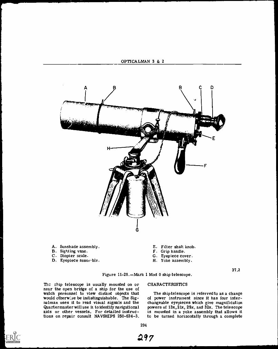
A. Sunshade assembly. E. Filter shaft knob.B. Sighting vane. F. Grip handle.C. Diopter scale. G. Eyepiece cover.D. Eyepiece asser,blv H. Yoke assembly.
37.2Figure 11-29.Mark 1 Mod 0 ship telescope.
The chip telescope is usually mounted on ornear the open bridge of a ship for the use ofwatch personnel to view distant objects thatwould otherwLse be indistinguishable. The Sig-nalman uses it to read visual signals and theQuartermaster will use it to identify navigationalaids or other vessels. For detailed instruc-tions on repair consult NAVSHIPS 250-624-3.
294
CHARACTERISTICS
The ship telescope is referred to as a changeof power instrument since it has four inter-changeable eyepieces which give magnificationpowers of 13x,21x, 25x, and 32x. The telescopeis mounted in a yoke assembly that allows itto be turned horizontally through a complete
7
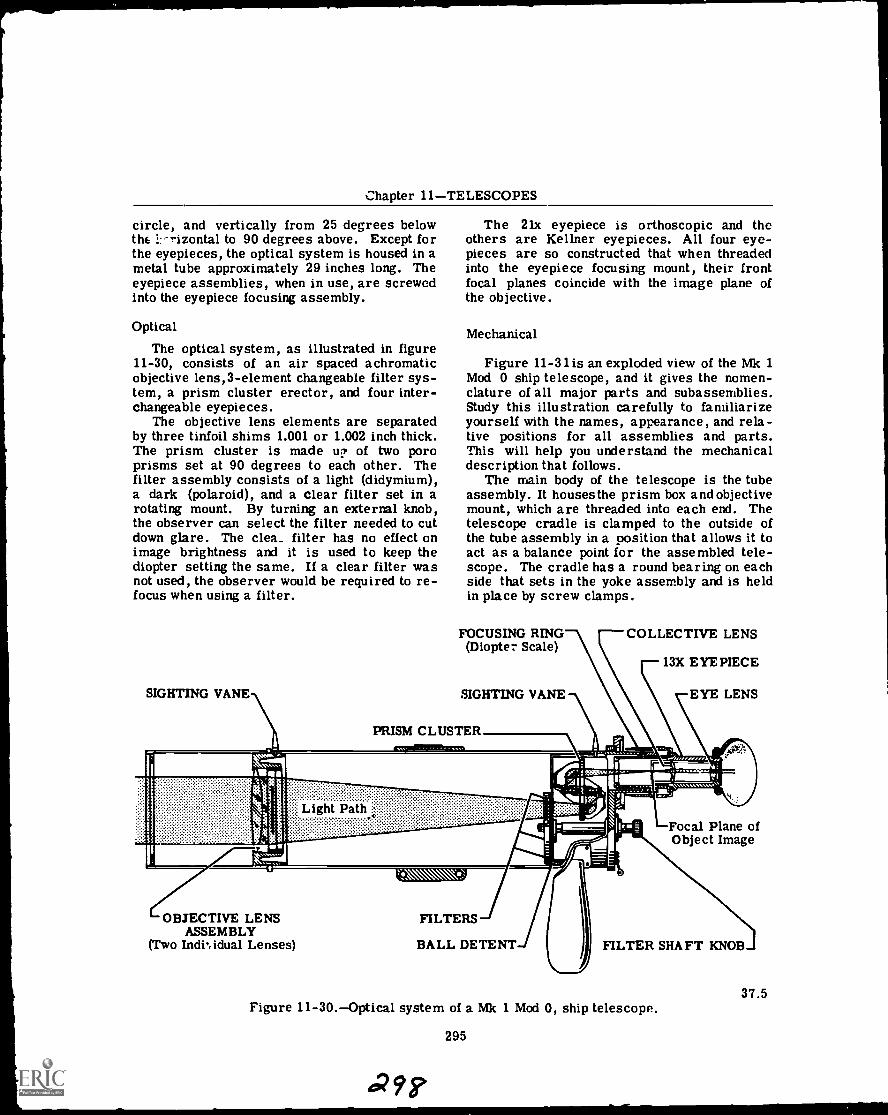
Chapter 11TELESCOPES
circle, and vertically from 25 degrees belowthe !.-^izontal to 90 degrees above. Except forthe eyepieces, the optical system is housed in ametal tube approximately 29 inches long. Theeyepiece assemblies, when in use, are screwedinto the eyepiece focusing assembly.
Optical
The optical system, as illustrated in figure11-30, consists of an air spaced achromaticobjective lens,3-element changeable filter sys-tem, a prism cluster erector, and four inter-changeable eyepieces.
The objective lens elements are separatedby three tinfoil shims 1.001 or 1.002 inch thick.The prism cluster is made u? of two poroprisms set at 90 degrees to each other. Thefilter assembly consists of a light (didymium),a dark (polaroid), and a clear filter set in arotating mount. By turning an external knob,the observer can select the filter needed to cutdown glare. The clew_ filter has no effect onimage brightness and it is used to keep thediopter setting the same. If a clear filter wasnot used, the observer would be required to re-focus when using a filter.
SIGHTING VANE
The 21x eyepiece is orthoscopic and theothers are Kellner eyepieces. All four eye-pieces are so constructed that when threadedinto the eyepiece focusing mount, their frontfocal planes coincide with the image plane ofthe objective.
Mechanical
Figure 11-31 is an exploded view of the Mk 1Mod 0 ship telescope, and it gives the nomen-clature of all major parts and subassemblies.Study this illustration carefully to familiarizeyourself with the names, appearance, and rela-tive positions for all assemblies and parts.This will help you understand the mechanicaldescription that follows.
The main body of the telescope is the tubeassembly. It housesthe prism box and objectivemount, which are threaded into each end. Thetelescope cradle is clamped to the outside ofthe tube assembly in a position that allows it toact as a balance point for the assembled tele-scope. The cradle has a round bearing on eachside that sets in the yoke assembly and is heldin place by screw clamps.
FOCUSING RING(Diopte Scale)
SIGHTING VANE
PRISM CLUSTER
COLLECTIVE LENS
13X EYEPIECE
EYE LENS
Focal Plane ofObject Image
OBJECTIVE LENSASSEMBLY
(Two Indhidual Lenses)
FILTERS
BALL DETENT FILTER SHAFT KNOB
37.5Figure 11-30.Optical system of a Mk 1 Mod 0, ship telescope.
295
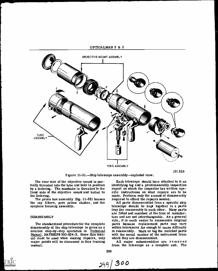
OPTICALMAN 3 & 2
OBJECTIVE MOUNT ASSEMBLY
TUBEASSEMBLY
YOKE ASSEMBLY
Figure 11-31.Ship telescope assemblyexploded view.
The rear side of the objective mount is par-tially threaded into the tube and held in positionby a lockring. The sunshade is threaded to thefront side of the objective mount and butted tothe lockring.
The prism box assembly (fig. 11-32) housesthe ray filters, poro prism cluster, and theeyepiece focusing assembly.
DISASSEMBLY
The standardized procedure for the completedisassembly of the ship telescope is given as adetailed step-by-step operation in TechnicalManual, NAVSHIPS 250-624-3. Since this man-ual must be used when making repairs, onlymajor points will be discussed in this trainingmanual.
296
137.528
Each telescope should have attached to it anidentifying tag and a predisassembly inspectionreport on which the inspector has written spe-cific instructions on what repairs are to bemade. Perform only the amount of disassemblyrequired to effect the repairs needed.
All parts disassembled from a specific shiptelescope should be kept together in a partstray for reassembly to each other. Many partsare fitted and matched at the time of manufac-ture and are not interchangeable. As a generalrule, it is much easier to reassemble originalparts because replacement parts may varywithin tolerances far enough to cause difficultyin reassembly. Mark or tag the matched partswith the serial number of the instrument fromwhich they are disassembled.
All major subassemblies are remove dfrom the telescope as a complete unit. The
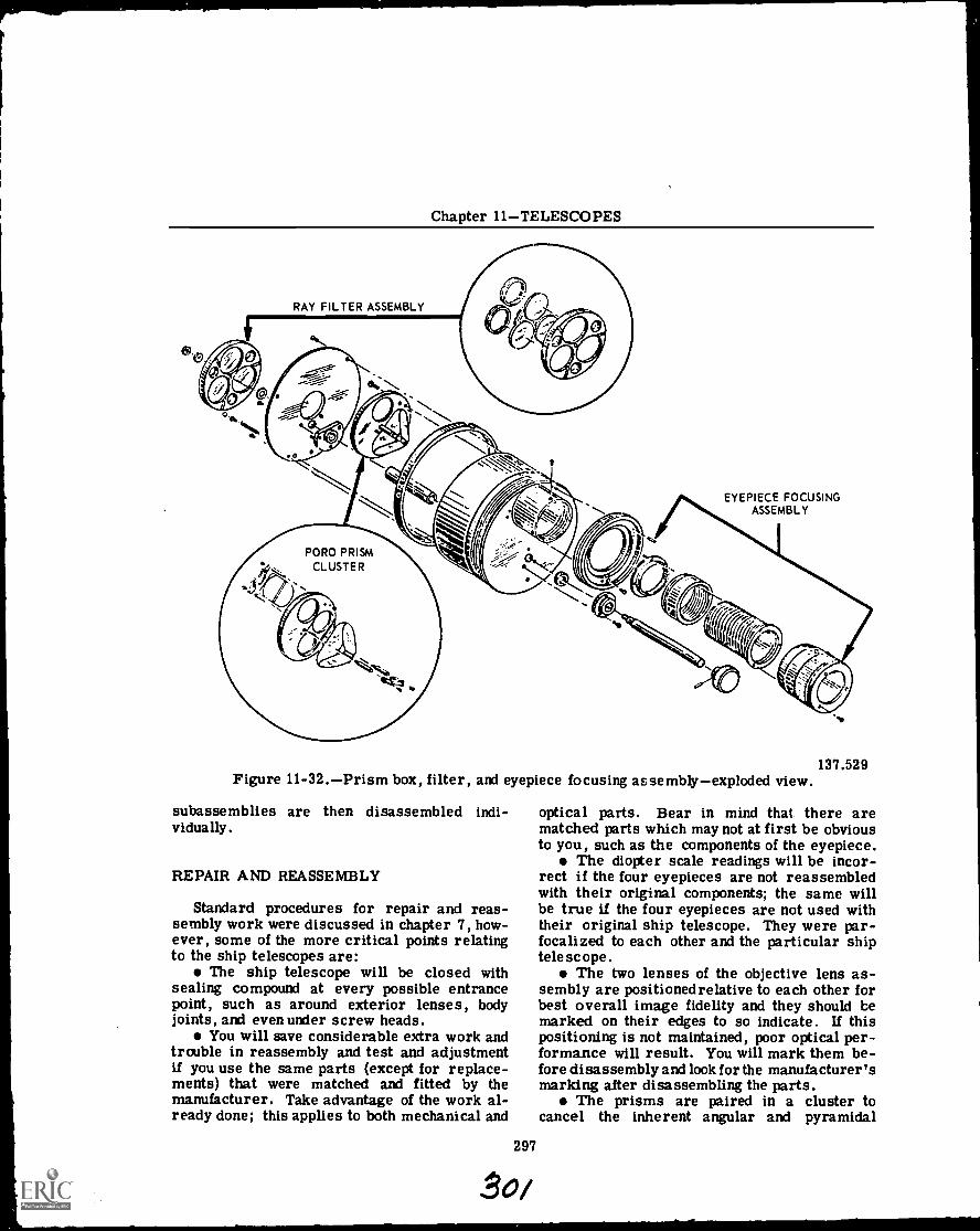
Chapter 11TELESCOPES
RAY FILTER ASSEMBLY
EYEPIECE FOCUSINGASSEMBLY
Figure 11-32.Prism box, filter, and eyepiece focusing assemblyexploded view.
subassemblies are then disassembled indi-vidually.
REPAIR AND REASSEMBLY
Standard procedures for repair and reas-sembly work were discussed in chapter 7, how-ever, some of the more critical points relatingto the ship telescopes are:
The ship telescope will be closed withsealing compound at every possible entrancepoint, such as around exterior lenses, bodyjoints, and even under screw heads.
You will save considerable extra work andtrouble in reassembly and test and adjustmentif you use the same parts (except for replace-ments) that were matched and fitted by themanufacturer. Take advantage of the work al-ready done; this applies to both mechanical and
297
137.529
optical parts. Bear in mind that there arematched parts which may not at first be obviousto you, such as the components of the eyepiece.
The diopter scale readings will be incor-rect if the four eyepieces are not reassembledwith their original components; the same willbe true if the four eyepieces are not used withtheir original ship telescope. They were par-focalized to each other and the particular shiptelescope.
The two lenses of the objective lens as-sembly are positioned relative to each other forbest overall image fidelity and they should bemarked on their edges to so indicate. If thispositioning is not maintained, poor optical per-formance will result. You will mark them be-fore disassembly and look for the manufacturer'smarking after disassembling the parts.
The prisms are paired in a cluster tocancel the inherent angular and pyramidal
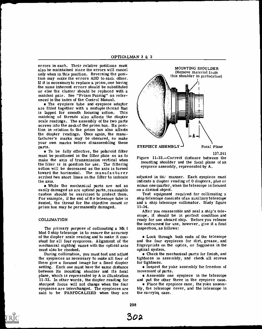
OPTICALMAN 3 & 2
errors in each. Their relative positions mustalso be maintained since the errors will cancelonly when in this position. Reversing the posi-tion may make the errors ADD to each other.If it is necessary to replace a prism, one havingthe same inherent errors should be substitutedor else the cluster should be replaced with amatched pair. See "Prism Pairing" as refer-enced in the index of the Control Manual.
The eyepiece tube and eyepiece adaptorare fitted together with a sextuple thread thatis lapped for smooth focusing action. Thismatching of threads also affects the diopterscale readings. The assembly of the two partsscrews into the neck of the prism box. Its posi-tion in relation to the prism box also affectsthe diopter readings. Once again, the manu-facturer's marks may be obscured, so makeyour own marks before disassembling theseparts.
To be fully effective, the polaroid filtermust be positioned in the filter plate so as tomake the axis of transmission vertical whenthe filter is in position for use. The filteringaction will be decreased as the axis is turnedtoward the horizontal. The ma nu f a c tu r erscribed two short lines on the filter to indicatethe axis.
While the mechanical parts are not aseasily damaged as are optical parts, reasonablecaution should be exercised to protect them.For example, if the end of the telescope tube isdented, the thread for the objective mount orprism box may be permanently damaged.
COLLIMATION
The primary purpose of collimating a Mk 1Mod 0 ship telescope is to ensure the accuracyof the diopter scale reading and to make it con-stant for all four eyepieces. Alignment of themechanical sighting vanes with the optical axismust also be checked.
During collimation, you must test and adjustthe eyepieces as necessary to make all four ofthem give a focused image for a fixed dioptersetting. Each one must have the same distancebetween its mounting shoulder and its focalplane, which is represented by A in illustration11-33. In other words, the diopter reading forsharpest focus will not change when the foureyepieces are interchanged. The eyepieces aresaid to be PARFOCALIZED when they are
298
MOUNTING SHOULDER(Remove material from
this shoulder to parfocalize)
LA.1
EYEPIECE ASSEMBLY Focal Plane
137.241Figure 11-33.Correct distance between the
mounting shoulder and the focal plane of aneyepiece assembly, represented by A.
adjusted in thi:- manner. Each eyepiece mustindicate a diopter reading of 0 diopters, plus orminus one quarter, when the telescope is focusedon a distant object.
Test equipment required for collimating aship telescope consists of an auxiliary telescopeand a ship telescope collimator. Study figure11-34.
After you reassemble and seal a ship's tele-scope, it should be in perfect condition andready for use aboard ship. Before you releasethe instrument for use, however, give it a finalinspection, as follows:
Look through both ends of the telescopeand the four eyepieces for dirt, grease, andfingerprints on the optics, or fogginess in theoptical system.
Check the mechanical parts for finish, andtightness in assembly, and check all screwsfor tightness.
Inspect the yoke assembly for freedom ofmovement of parts.
Assemble one eyepiece in the telescopeand put the other three in the eyepiece case.
Place the eyepiece case, the yoke assem-bly, the telescope cover, and the telescope inthe carryinc case.
Sap.
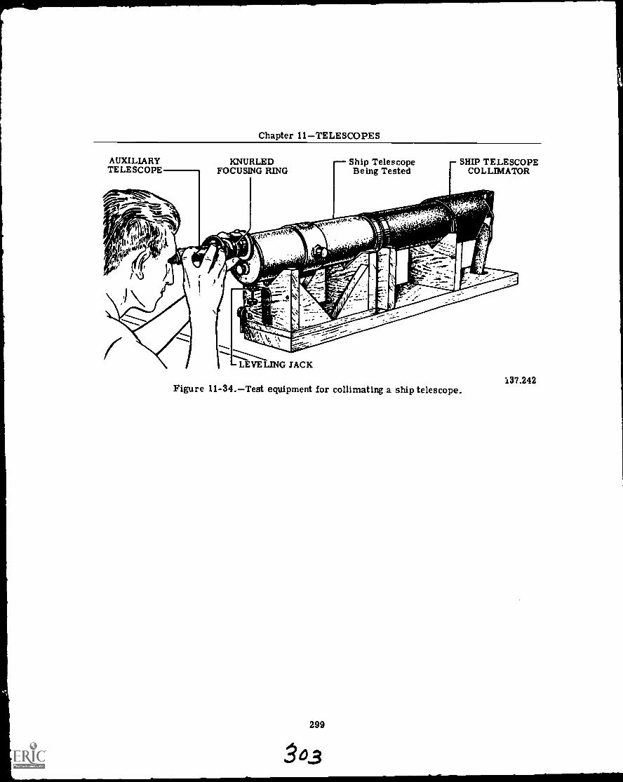
Chapter 11TELESCOPES
AUXILIARYTELESCOPE
KNURLEDFOCUSING RING
Ship Telescope rSHIP TELESCOPEBeing Tested i COLLIMATOR
(Figure 11-34.Test equipment for collimating a ship telescope.
299
0..3
137.242
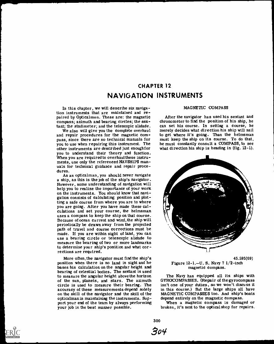
CHAPTER 12
NAVIGATION INSTRUMENTS
In this chapter, we will describe six naviga-tion instruments that are maintained and re-paired by Opticalmen. These are: the magneticcompass; azimuth and bearing circles; the sex-tant; the stadimeter; and the telescopic alidade.
We also will give you the complete overhauland repair procedures for the magnetic com-pass, since there are no technical manuals foryou to use when repairing this instrument. Theother instruments are described just enoughforyou to understand their theory and function.When you are required to overhaul these instru-ments, use only the referenced NAVSHIPS man-uals for technical guidance and repair proce-dures.
As an opticalman, you should never navigatea ship, as this is the job of the ship's navigator.However, some understanding of navigation willhelp you to realize the importance of your workon the instruments. You should know that navi-gation consists of calculating position and plot-ting a safe course from where you are to whereyou are going. After you have made these cal-culations and set your course, the helmsmanuses a compass to keep the ship on that course.Because of ocean current and wind, the ship willperiodically be drawn away from the projectedpath of travel and course corrections must bemade. If you are within sight of land, you canuse a bearing circle or telescopic alidade tomeasure the bearing of two or more landmarksto determine your ship's position and what cor-rections are required.
More often, the navigator must find the ship'sposition when there is no land in sight and hebases his calculation on the angular height andbearing of celestial bodies. The sextant is usedto measure the angular height above the horizonof the sun, planets, and stars. The azimuthcircle is used to measure their bearing. Theaccuracy of these measurements depend solelyon the skill of the navigator and the skill of theopticalman in maintaining the instruments. Sup-port your end of the team by always performingyour job in the best manner possible.
MAGNETIC COMPASS
After the navigator has used his sextant andchronometer to find the position of his ship, hecan set his course. In setting a course, hemerely decides what direction his ship will sailto get where it's going. Than the helmsmanmust keep the ship on its course. To do that,he must constantly consult a COMPASS, to seewhat direction his ship is heading in (fig. 12-1).
AL_
45.595(69)Figure 12-1.U. S. Navy 7 1/2-inch
magnetic compass.
The Navy has equipped all its ships withGYROCOMPASSES. (Repair of the gyrocompassisn't one of your duties, so we won't discuss itin this course.) But the large ships all haveMAGNETIC COMPASSES too. And ship's boatsdepend entirely on the magnetic compass.
When a magnetic compass is damaged orbroken, it's sent to the optical shop for repairs.
Chapter 12NAVIGATION INSTRUMENTS
PRINCIPLE OF OPERATION
Somebody in Magnesia (on the coast of theAegean Sea) discovered a bug time ago thatcertain stones (magnetite or lodestone) couldattract iron. Another person learned that whenhe rubbed an iron bar with a piece of lodestonethe bar became a magnet. A Chinaman thenlearned that when he attached little floats to amagnetized needle and put it in water the needlepointed approximately North and South. Sometime later, an Italian navigator balanced theneedle on a pivot and Learned that its action thenwas the same as when it was balanced on water.
These people learned through experimenta-tion the principle of operation of a magneticcompass. From the needle on floats or a woodendisk to the compass box and hanging compass,action of the compass needle has always beenthe sameonly the method for holding it haschanged.
You can learn how a magnetic compass op-erates by doing a little experimenting on yourown. Hold a small compass level and observethe action of its needle. Regardless of thedirection you turn the compass, its needle al-ways points north; and by turning the compassuntil the N on the card is under the point of theneedle, you can determine any direction.
If you take the needle out of the compass,youwill find that it is magnetized at both ends.Each end attracts iron; but ONLY ONE end willpoint North. The reason for this action is thatthere are TWO KINDS of magnetism North andSouth and every magnet has both kinds. If wecall the points where magnetism in a magnet isstrongest the magnetic poles, every magnet hasa NORTH - SEEKING pole and a SOUTH-SEEKINGpole. In a bar magnet, or in a compass needle,the two poles are at the ends.
The earth itself is a HUGE magnet, with anorth magnetic pole in northern Canada and asouth magnetic pole in Antarctica. Like polesREPEL each other; unlike poles ATTRACT eachother. Put two bar magnets side by side, withboth north poles together. and observe whathappens. The two magnets repel each other; butif you turn ONE magnet end for end, the twomagnets attract each other.
Most ships carry two or more magnetic com-passes like the one illustrated in figure 12-1.This is a U.S. Navy 7 1/2-inch compass.
Wet compasses are liquid filled, usually withvarsol or alcohol and water. Other compassescontain no liquid and are designated as dry
compasses, but this type of compass is seldomused in the Navy. A wet compass consists of abowl filled with liquid, which supports a hollowfloat to which the compass card and magnetsare attached. The liquid steadies the compassagainst the motion of the ship and the shock ofgunfire; and since the liquid supports most ofthe weight of the magnets, it reduces the pres-sure and friction on the pivot.
Navy magnetic compasses vary slightly withrespect to purpose. Part A of figure 12-2 showsa standard 4-inch boat compass, and part B ofthis illustration shows a 6 3/4-inch steeringcompass.
The size of a compass is designated by thediameter (in inchen) of its card. The compassshown in figure 13-3 has a translucent card, orone with perforated markings; and a light in itsstand shines up through a ground-glass plate inthe bottom of the compass to illuminate the card.
The compass card of a pocket compass isprinted on the bottom of the case, and its needleis not hindered in its motion. A Navy compass.onthe other hand, has no needle. The steersmanis not interested in knowing the direction ofNorth; all he wants to know is the direction hisship is heading.
The compass card of a magnetic compass ismounted on a pivot and the magnets are attachedto the card, so that the card itself will swing andpoint its zero mark to the north. Observe onthe bowl of the compass shown in figure 12-2the LUBBER'S LINE. The compass is alwaysmounted so that an imaginary line from thecompass pivot to the lubber's line is parallelto the ship's keel; so, to read the ship's head-ing, you read the graduation on the compasscard AT THE LUBBER'S LINE. When the shipchanges its course, the compass card stillpoints its zero graduation toward north; but theship, the compass bowl, and the lubber's lineall turnunder the card.
In order that it will stay level even when theship is rolling and pitching, the bowl of a mag-netic compass is mounted in gimbal rings. Thebottom of the bowl is very heavy, to help keepthe compass level. The compass is mountedin a stand, called a BINNACLE. See illustration12-3. The two hollow soft iron spheres on thesides of the binnacle are called quadrantal cor-rectors for deviation. (Deviation changesdirec-tion every 90°, hence the name QUADRANTAL.)The earth's magnetic field magnetizes thesespheres by induction. The induced magnetism ofthe spheres counteracts the induced magnetism
301
oS
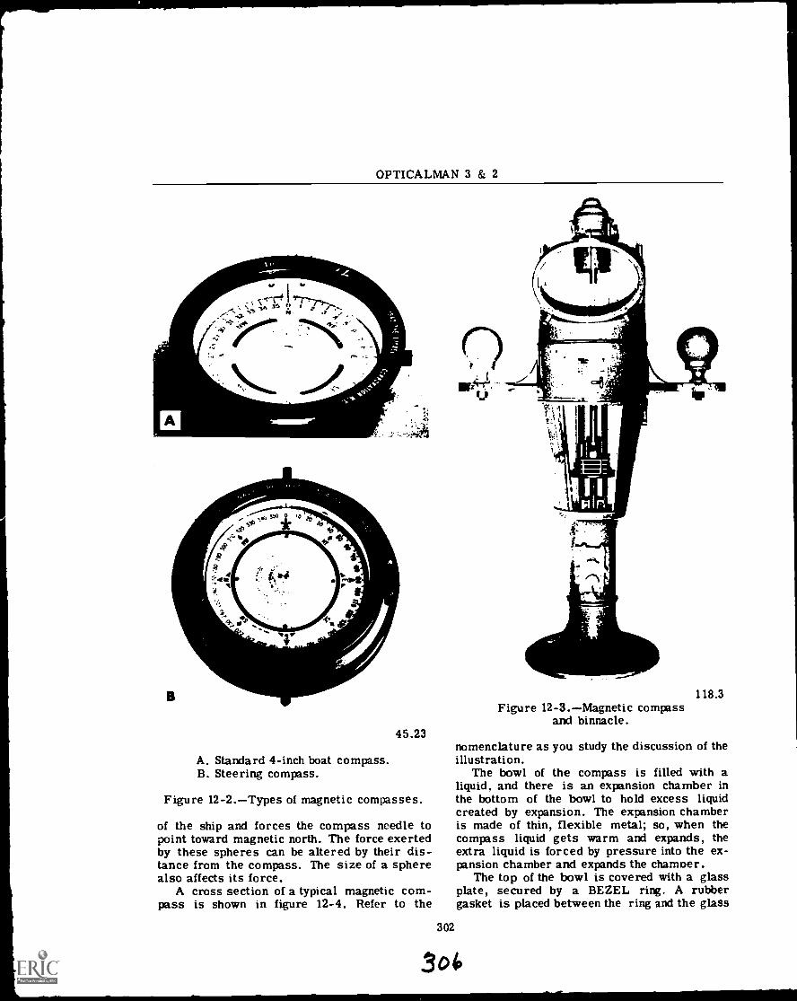
OPTICALMAN 3 & 2
4,, 1
B
A. Standard 4-inch boat compass.B. Steering compass.
45.23
Figure 12-2.Types of magnetic compasses.
of the ship and forces the compass needle topoint toward magnetic north. The force exertedby these spheres can be altered by their dis-tance from the compass. The size of a spherealso affects its force.
A cross section of a typical magnetic com-pass is shown in figure 12-4. Refer to the
302
118.3Figure 12-3.Magnetic compass
and binnacle.
nomenclature as you study the discussion of theillustration.
The bowl of the compass is filled with aliquid, and there is an expansion chamber inthe bottom of the bowl to hold excess liquidcreated by expansion. The expansion chamberis made of thin, flexible metal; so, when thecompass liquid gets warm and expands, theextra liquid is forced by pressure into the ex-pansion chamber and expands the chamber.
The top of the bowl is covered with a glassplate, secured by a BEZEL ring. A rubbergasket is placed between the ring and the glass
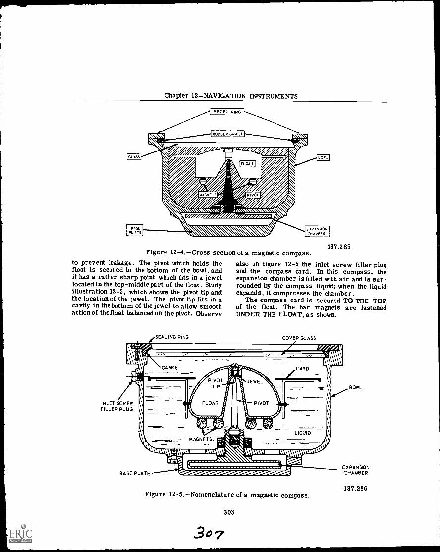
Chapter 12NAVIGATION INSTRUMENTS
Figure 12-4.Cross section of a magnetic compass.to prevent leakage. The pivot which holds thefloat is secured to the bottom of the bowl, andit has a rather sharp point which fits in a jewellocated in the top-middle part of the float. Studyillustration 12-5, which shows the pivot tip andthe location of the jewel. The pivot tip fits in acavity in the bottom of the jewel to allow smoothaction of the float balanced on the pivot. Observe
SEALING RING
137.285
also in figure 12-5 the inlet screw filler plugand the compass card. In this compass, theexpansion chamber is filled with air and is sur-rounded by the compass liquid; when the liquidexpands, it compresses the chamber.
The compass card is secured TO THE TOPof the float. The bar magnets are fastenedUNDER THE FLOAT, as shown.
COVER GLASS
GASKET
_
CARD
INLET SCREWFILLER PLUG
MAGNETS
\,oitc,
RUM IMMAMptutOli%%mu IMMUUN
glewmmwBASE PLATE
Figure 12-5.Nomenclature of a magnetic compass.
303
BOWL
EXPANSIONCHAMBER
137.286
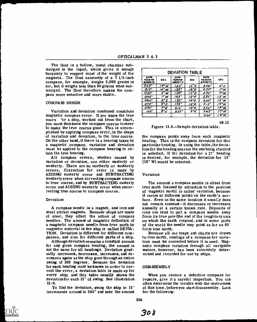
OPTICALMAN 3 & 2
The float is a hollow, metal chamber sub-merged in the liquid, which gives it enoughbuoyancy to support most i)f the weight of themagnets. The float assembly of a 7 1/2-inchcompass, for example, weighs 3,060 grains inair, but it weighs less than 90 grains when sub-merged. The float therefore makes the com-pass more sensitive and more stable.
COMPASS ERROR
Variation and deviation combined constitutemagnetic compass error. If you know the truecours 'or a ship, worked out from the chart,you must thenknow the compass course to steerto make the true course good. This is accom-plished by applying compass error, in the shapeof variation and deviation, to the true course.On the other hand, if there is a bearing taken bya magnetic compass, variation and deviationmust be applied to the compass bearing to ob-tain the true bearing.
All compass errors, whether caused byvariation or deviation, are either easterly orwesterly. There are no northerly or southerlyerrors. Correction for error is made byADDING easterly error and SUBTRACTINGwesterly error when correcting compass courseto true course, and by SUBTRACTING easterlyerror and ADDING westerly error when uncor-recting true course to compass course.
Deviation
A compass needle is a magnet, and iron andsteel attract magnets. Because ships are madeof steel, they affect the action of compassneedles. The amount of magnetic deflection ofa magnetic compass needle from true north bymagnetic material in the ship is called DEVIA-TION. Deviation is different for different com-passes, and also for different parts of a ship.
Although deviation remains a constant amountfor any given compass heading, the amount isnot the same for all headings. Deviation grad-ually increases, decreases, increases, and de-creases again as the ship goes through an entireswing of 360 degrees. Because the deviationfor each heading must be known in order to cor-rect the error, a deviation table is made up forevery ship; and this table usually shows thedeviationfor each 15° of swing. See illustration12 -6.
To find the deviation, swing the ship in 15°increments around to 360° and note the amount
DEVIATION TABLESNITS
HEADINGMAGNETIC
DEV.slims
HEADINGMAGNETIC
DEV.SHIPS
HEADINGMAGNETIC
DEV.
000. /sew / 2 0' /S. E 2410' 4-* E0/5' /0' w /35* /6'E 255° / °W030' 5' w /50' 12'E 270' 7'w01,15- /' W /65' 13'E 275' 12'w060' 2'E /80' /40E 300' 15-0f075* C'E /95' irE 3/5' /9'WOW 7*E 2/0' /VE 330' /9'01/05' C'''E 225' 9"E 34.5' /7W
360' / ''IV
69.12Figure 12.6.Sample deviation table.
the compass points away from each magneticheading. This is the compass deviation for thatparticular heading. In using the table, the devia-tion for the heading nearest the one being checkedis selected. If the deviation for a 17° headingis desired, for example, the deviation for 15°(10° W) would be selected.
Variation
The amount a compass needle is offset fromtrue north (caused by attraction to the positionof magnetic north) is called variation, becauseit varies at different points on the earth's sur-face. Even in the same location it usual:y doesnot remain constantit decreases or increasesannually at a certain known rate. Deposits ofiron ore tend to pull a compass needle awayfrom its true pole (the end of the imaginary axison which the earth rotates), and in some partsof the world the needle may point as far as 60'from true north.
Because all our maps and charts are drawnto true north, readings of a compass for varia-tion must be corrected before it is used. Mag-netic compass variation through all navigablewaters, however, has been accurately deter-mined and recorded for use by ships.
DISASSEMBLY
When you receive a defective compass forrepairs, give it a careful inspection. You canoften determine the trouble with the instrumentat this time, before you start disassembly. Lookfor the following:
304
30 8
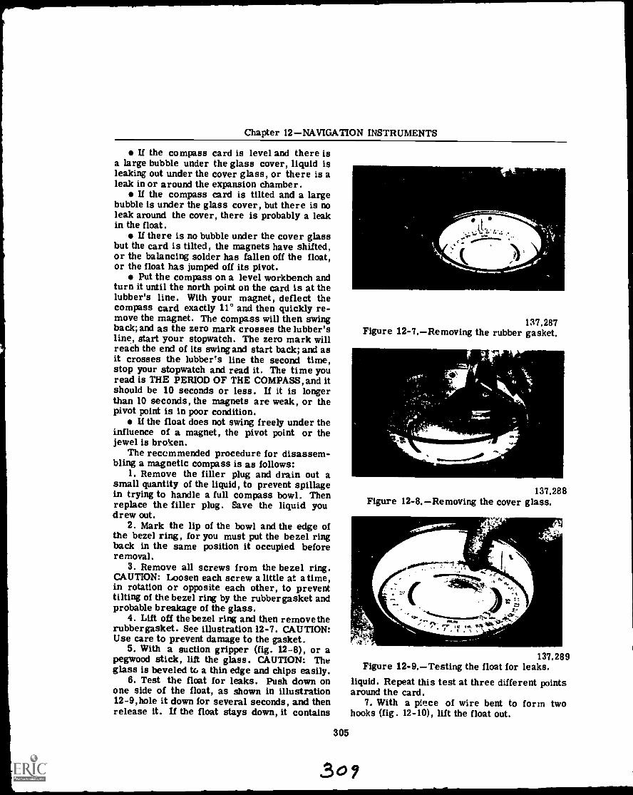
Chapter 12NAVIGATION INSTRUMENTS
If the compass card is level and there isa large bubble under the glass cover, liquid isleaking out under the cover glass, or there is aleak in or around the expansion chamber.
If the compass card is tilted and a largebubble is under the glass cover, but there is noleak around the cover, there is probably a leakin the float.
U there is no bubble under the cover glassbut the card is tilted, the magnets have shifted,or the balancing solder has fallen off the float,or the float has jumped off its pivot.
Put the compass on a level workbench andturn it until the north point on the card is at thelubber's line. With your magnet, deflect thecompass card exactly 11° and then quickly re-move the magnet. The compass will then swingback; and as the zero mark crosses the lubber'sline, start your stopwatch. The zero mark willreach the end of its swing and start back; and asit crosses the lubber's line the second time,stop your stopwatch and read it. The time youread is THE PERIOD OF THE COMPASS, and itshould be 10 seconds or less. If it is longerthan 10 seconds, the magnets are weak, or thepivot point is in poor condition.
U the float does not swing freely under theinfluence of a magnet, the pivot point or thejewel is broken.
The recommended procedure for disassem-bling a magnetic compass is as follows:
1. Remove the filler plug and drain out asmall quantity of the liquid, to prevent spillagein trying to handle a full compass bowl. Thenreplace the filler plug. Save the liquid youdrew out.
2. Mark the lip of the bowl and the edge ofthe bezel ring, for you must put the bezel ringback in the same position it occupied beforeremoval.
3. Remove all screws from the bezel ring.CAUTION: Loosen each screw a little at atime,in rotation or opposite each other, to preventtilting of the bezel ring by the rubber gasket andprobable breakage of the glass.
4. Lift off the bezel ring and then remove therubber gasket. See illustration 12-7. CAUTION:Use care to prevent damage to the gasket.
5. With a suction gripper (fig. 12-8), or apegwood stick, lift the glass. CAUTION: Theglass is beveled to a thin edge and chips easily.
6. Test the float for leaks. Push down onone side of the float, as shown in illustration12-9,hole it down for several seconds, and thenrelease it. If the float stays down, it contains
305
137.287Figure 12-7.Removing the rubber gasket.
137.288Figure 12-8.Removing the cover glass.
r ,
a-;"4.:. "
st.
414w *etI ,
137.289Figure 12-9.Testing the float for leaks.
liquid. Repeat this test at three different pointsaround the card.
7. With a piece of wire bent to form twohooks (fig. 12-10), lift the float out.
309
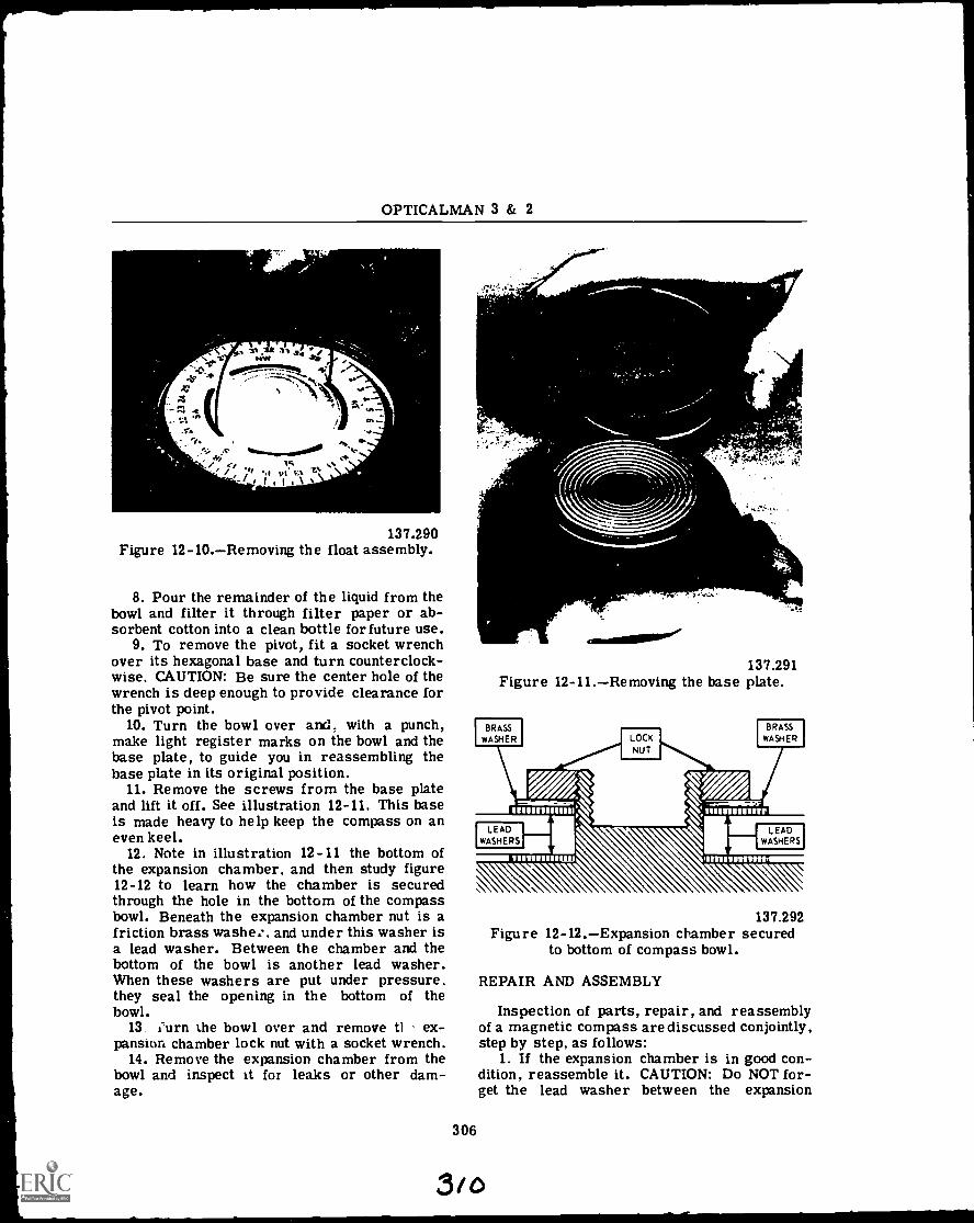
OPTICALMAN 3 & 2
, VI .3.2 1 34 ,eV tiV4 Rea,ir -
-,.,--c. ?...-. 4. 0,. , .% r.-. ...N. .
1 f pis too Mk
.r4
".1C. 141.,....0111001.
/S/
I ,
137.290Figure 12-10.Removing the float assembly.
8. Pour the remainder of the liquid from thebowl and filter it through filter paper or ab-sorbent cotton into a clean bottle for future use.
9. To remove the pivot, fit a socket wrenchover its hexagonal base and turn counterclock-wise. CAUTION: Be sure the center hole of thewrench is deep enough to provide clearance forthe pivot point.
10. Turn the bowl over and. with a punch,make light register marks on the bowl and thebase plate, to guide you in reassembling thebase plate in its original position.
11. Remove the screws from the base plateand lift it off. See illustration 12-11. This baseis made heavy to help keep the compass on aneven keel.
12. Note in illustration 12-11 the bottom ofthe expansion chamber, and then study figure12-12 to learn how the chamber is securedthrough the hole in the bottom of the compassbowl. Beneath the expansion chamber nut is afriction brass washes , and under this washer isa lead washer. Between the chamber and thebottom of the bowl is another lead washer.When these washers are put under pressure,they seal the opening in the bottom of thebowl.
13. ;urn the bowl over and remove tt ex-pansion chamber lock nut with a socket wrench.
14. Remove the expansion chamber from thebowl and inspect it for leaks or other dam-age.
nj
r
mommosillsor/
137.291Figure 12-11.Removing the base plate.
BRASSWASHER LOCK
NUT
BRASSWASHER
14,7
40.impRF
11 1111111111W 11111111111MI
LEADWASHERS
LEADWASHERS
306
137.292Figure 12-12.Expansion chamber secured
to bottom of compass bowl.
REPAIR AND ASSEMBLY
Inspection of parts, repair, and reassemblyof a magnetic compass are discussed conjointly,step by step, as follows:
1. If the expansion chamber is in good con-dition. reassemble it. CAUTION: Do NOT for-get the lead washer between the expansion
3/o

Chapter 12NAVIGATION INSTRUMENTS
chamber and the bottom of the bowl. If thiswasher is not in perfect condition, replace it.
2. Replace the second lead washer, insidethe bowl and replace the brass friction washer.If necessary, use a new washer. Start thehexagonal lock nut by hand and tighten it with asocket wrench. NOTE: Use enough tension tomake a good seal at the lead washers.
3. Put the base plate back into position; thenreplace the base plate screws and tighten them.CAUTION: Be sure to line up your two marksyou made during disassembly; otherwise, thecompass will be out of balance.
4. With a magnifying glass, inspect the pivotpoint for wear. Study illustration 12-13. Themagnified pivot in part A of figure 12-13 isbadly worn. Observe the round appearance.The pivot point shown in part B of this illustra-tion has proper shape. NOTE: A badly wornpivot point makes a compass sluggish.
1
A. Worn pivot point.B. Good pivot point.
137.293Figure 12-13.Pivot points.
5. If the pivot point is worn, put it in a latheand reshape it with a fine carborundum slip(fig. 12-14). Then polish it with an Arkansasoil stone and inspect again for correctness ofshape. The tip of the pivot should have a radiusof .005 inch.
6. Remove the screw from the top of the floatand use a piece of peg-wood with a rounded endto push the jewel and its spacer out of the float.Study illustration 12-15. Then hone a steelneedle to a sharp point on an oil stone and restit on your finger nail (fig. 12-16). If it slidesunder its own weight, it is NOT sharp enough;if it catches on your thumb nail, it has correctsharpness. Now slide the needle under its ownweight over the whole bearing surface of the
307
137.294Figure 12-14.Shaping a worn pivot point.
, \ i I I i
o' \ 11e. hl" r: ' :
1i.VI
ckitt \
`mow
111.7......410f11"414
,fiiit-* ,:pie:.:0;..,, .:...
-4-
cr
137.295Figure 12-15.Removing the jewel
from the float.jewel, as shown in figure 12-17. If the surfaceof the jewel has a crack or a pit, it will snagthe fine point of the needle. NOTE: If the jewelis defective. replace it.
7. Test the float for leaks by submerging itin warm water (120 F). The heat will expandthe air inside the float; and if there are leaks in
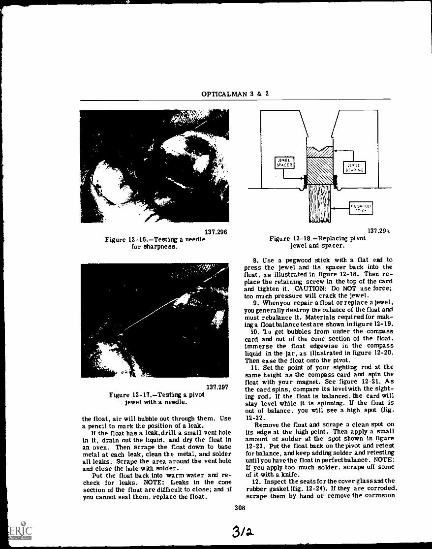
OPTICALMAN 3 & 2
"Tir,-., '
137.296Figure 12-16.Testing a needle
for sharpness.
137.297Figure 12-17.Testing a pivot
jewel with a needle.
the float, air will bubble out through them. Usea pencil to mark the position of a leak.
If the float has a leak, drill a small vent holein it, drain out the liquid, and dry the float inan oven. Then scrape the float down to basemetal at each leak, clean the metal, and solderall leaks. Scrape the area around the vent holeand close the hole with solder.
Put the float back into warm water and re-check for leaks. NOTE: Leaks in the conesection of the float are difficult to close; and ifyou cannot seal them, replace the float.
137.29:tFigure 12-18.Replacing pivot
jewel and spacer.
8. Use a pegwood stick with a flat end topress the jewel and its spacer back into thefloat, as illustrated in figure 12-18. Then re-place the retaining screw in the top of the cardand tighten it. CAUTION: Do NOT use force;too much pressure will crack the jewel.
9. Whenyou repair a float or replace a jewel,you generally destroy the balance of the float andmust rebalance it. Materials required for mak-ing a float balance test are shown in figu re 12-19.
10. To get bubbles from under the compasscard and out of the cone section of the float,immerse the float edgewise in the compassliquid in the jar, as illustrated in figure 12-20.Then ease the float onto the pivot.
11. Set the point of your sighting rod at thesame height as the compass card and spin thefloat with your magnet. See figure 12-21. Asthe card spins, compare its levelwith the sight-ing rod. If the float is balanced. the card willstay level while it is spinning. If the float isout of balance, you will see a high spot (fig.12-22.
Remove the float and scrape a clean spot onits edge at the high point. Then apply a smallamount of solder at the spot shown in figure12-23. Put the float back on the pivot and retestfor balance, and keep adding solder and retestinguntil you have the float in perfect balance. NOTE:If you apply too much solder, scrape off someof it with a knife.
12. Inspect the seats for the cover glass and therubber gasket (fig. 12-24). If they are corroded.scrape them by hand or remove the corrosion
308
3/.
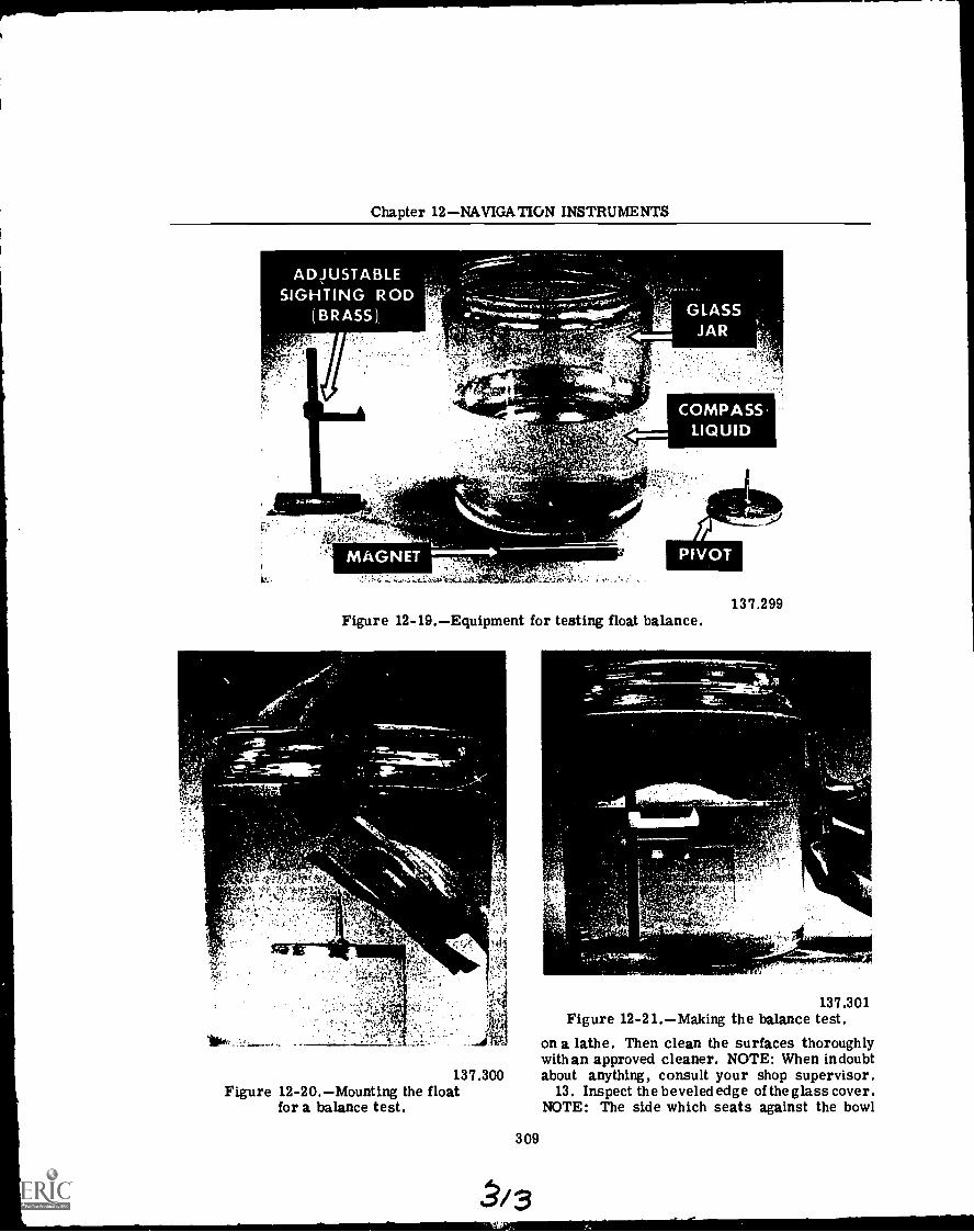
Chapter 12NAVIGATION INSTRUMENTS
137.299Figure 12-19.Equipment for testing float balance.
137.300Figure 12-20.Mounting the float
for a balance test.
309
-.-7/111.11Seal/1113.1m.a....
137.301Figure 12-21.Making the balance test.
on a lathe. Then clean the surfaces thoroughlywithan approved cleaner. NOTE: When indoubtabout anything, consult your shop supervisor.
13. Inspect the beveled edge of the glass cover.NOTE: The side which seats against the bowl
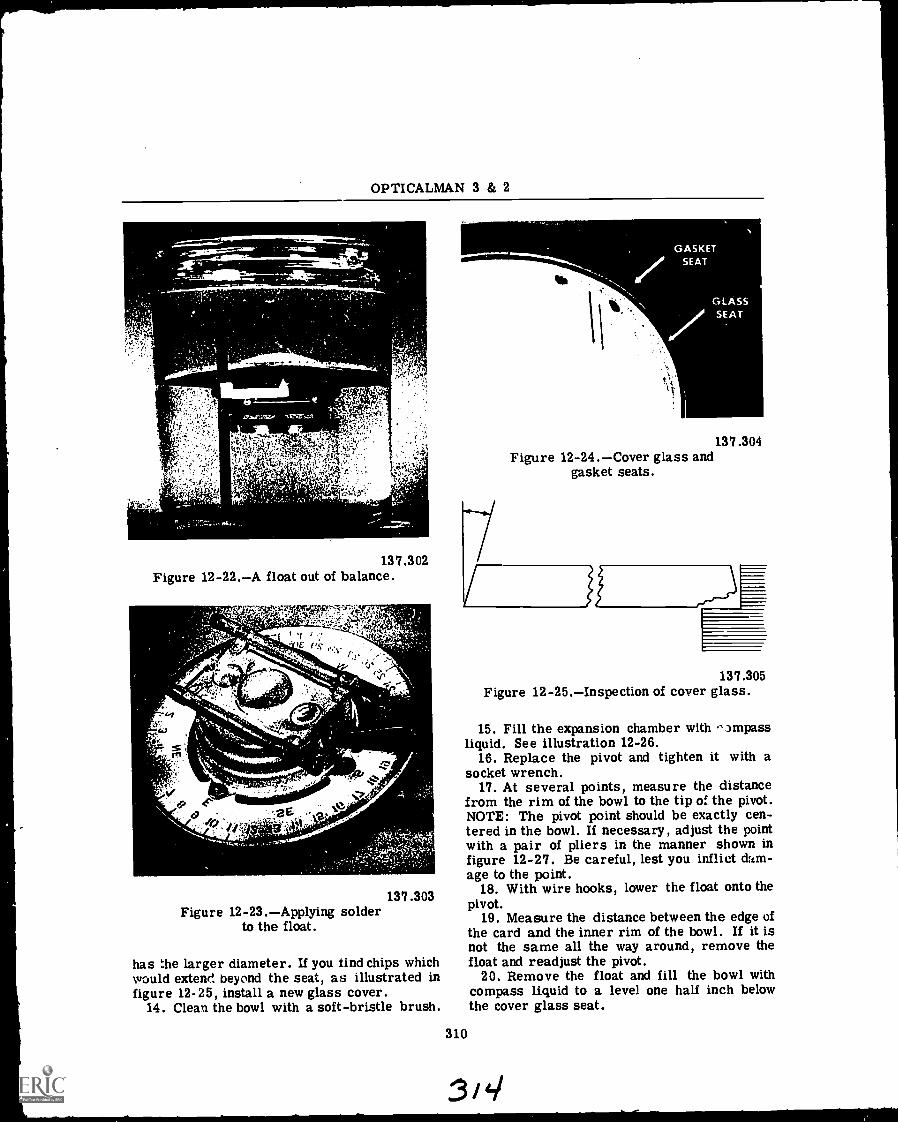
OPTICALMAN 3 & 2
137.302Figure 12-22.A float out of balance.
re:tewr
vf
f">;-.( P-7-7f
)e.
e-2E °".1
137.303Figure 12-23.Applying solder
to the float.
has the larger diameter. If you find chips whichwould extend beyond the seat, as illustrated infigure 12-25, install a new glass cover.
14. Clean the bowl with a soft-bristle brush.
41 I
137.304Figure 12-24.Cover glass and
gasket seats.
137.305Figure 12-25.Inspection of cover glass.
15. Fill the expansion chamber with .)mpassliquid. See illustration 12-26.
16. Replace the pivot and tighten it with asocket wrench.
17. At several points, measure the distancefrom the rim of the bowl to the tip of. the pivot.NOTE: The pivot point should be exactly cen-tered in the bowl. If necessary, adjust the pointwith a pair of pliers in the manner shown infigure 12-27. Be careful, lest you inflict dam-age to the point.
18. With wire hooks, lower the float onto thepivot.
19. Measure the distance between the edge ofthe card and the inner rim of the bowl. If it isnot the same all the way around, remove thefloat and readjust the pivot.
20. Remove the float and fill the bowl withcompass liquid to a level one half inch belowthe cover glass seat.
310
3i4./

Chapter 12NAVIGATION INSTRUMENTS
ti
137.306Figure 12-26.Filling expansion chamber.
137.307Figure 12-27.Adjusting the pivot
with pliers.
21. Replace the float and, with a pegwood sticksharpened to a chisel point, carefully place theglass in position.
22. Fit the rubber gasket around the edge ofthe cover glass (fig. 12-28). The ends of thegasket should meet perfectly. If they overlap,trim them to perfect fit; if the gasket is tooshort, install a new one.
23. Replace the bezel ring, insert the screws,and turn them tight with your fingers. Thenuse a screwdriver to tighten all screws, onehalf turn at a time in rotation, until the ring issecure.
TESTING AND ADJUSTING
The procedure for testing and adjusting yourreassembled compass is as follows:
t'4019qt.!
1,1V,f0t,rIV4,tl.N144'
'01 161244 Oita bit a"
311
137.308Figure 12-28.Replacing the rubber gasket.
r17 16 1,1' S- !",wso
a) 4.,
r, .4412#
wilowsLadkaf.a
137.309Figure 12-29.Testing for leaks around
the bezel ring.
1. To test for leaks around the bezel ring,make a screw to fit the filler hole and drill asmall hole through the center of the screw. In-sert the screw in the filler hole and fit a pieceof rubber tubing over the screw. Suck on thetube and then pinch it off (fig. 12-29). If thereare leaks around the ring, bubbles will risefrom them.
2. With a rubber bulb syringe, finish fillingthe bowl with liquid; then replace the filler ventplug and secure it.
3'6

OPTICALMAN 3 & 2
3. Put the compass in a warm place and letit stand for 24 hours, with the filler hole up.This amount of time allows trapped bubbles torise and dissolved air to come out of the com-pass liquid. NOTE: Less time is satisfactoryif the air is fairly warm. Remove bubbles byadding more liquid and then replace the plug.
4. Retest the period of the compass. Seestep 5 under DISASSEMBLY.
5. Test the compass for balance. To dothis, you need the material shown in illustra-tion 12-30. Mount the compass bowl on the V'sand put the level on the glass. NOTE: Be sureto center the level; otherwise, the level itselfmay unbalance the compass. See illustration12 -31.
137.310Figure 12-30.Equipment for testing
compass balance.
If your compass does not balance, file thelugs (projections by which the compass is held)to move the bearing edge over toward the heavyside (fig. 12-32). Make a light cut with your fileand test the balance. Repeat this process untilthe balance is perfect.
Now mount the compass in its gimbal ringand mount the ring on the V's (fig. 12-33). Testthe balance. If necessary, file the lugs (slightamount each time) of the gimbal ring until youhave the balance perfect.
AZIMUTH AND BEARING CIRCLES
The meaning of the terms AZIMUTH andTRUE BEARING is the same; namely, the direc-tion of an object from true north (measuredclockwise in degrees). In the Navy, however,
312
rtglk",0P"'A '
45.23Figure 12-31.Testing compass balance.
NEWCENTER OF
GRAVITY
NERVY 1 LIGHT
SIDE J S DE
PRESENTCENTER OF
GRAVITY
137.312Figure 12-32.Restoring compass balance.
there is a difference in the use of these twotermsAZIMUTH is used in connection withCELESTIAL BODIES, and TRUE BEARINGSare taken of TERRESTIAL OBJECTS. AQuartermaster, for example, takes a bearing ofa lighthouse, but he gets the azimuth of the sun.Relative bearing is the direction of an objectrelative to the heading of a ship (measured indegrees).
CONSTRUCTION FEATURES
The instrumentinstrument used for measuring all bear-ings (true and relative) is the BEARING CIRCLE
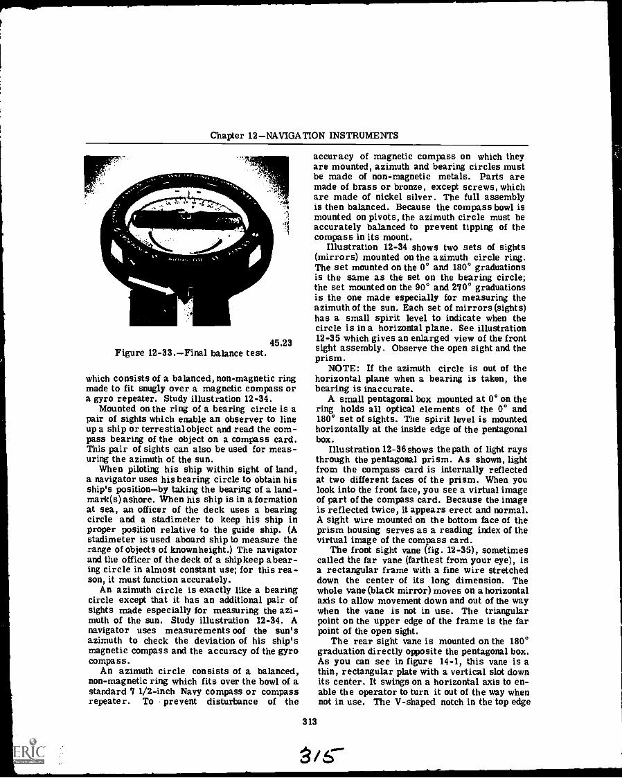
Chapter 12NAVIGATION INSTRUMENTS
45.23Figure 12-33.Final balance test.
which consists of a balanced, non-magnetic ringmade to fit snugly over a magnetic compass ora gyro repeater. Study illustration 12-34.
Mounted on the ring of a bearing circle is apair of sights which enable an observer to lineup a ship or terrestial object and read the com-pass bearing of the object on a compass card.This pair of sights can also be used for meas-uring the azimuth of the sun.
When piloting his ship within sight of land,a navigator uses his bearing circle to obtain hisship's positionby taking the bearing of a land-mark(s) ashore. When his ship is in a formationat sea, an officer of the deck uses a bearingcircle and a stadimeter to keep his ship inproper position relative to the guide ship. (Astadimeter is used aboard ship to measure therange of objects of known height.) The navigatorand the officer of the deck of a ship keep abear-ing circle in almost constant use; for this rea-son, it must function accurately.
An azimuth circle is exactly like a bearingcircle except that it has an additional pair ofsights made especially for measuring the azi-muth of the sun. Study illustration 12-34. Anavigator uses measurements oof the sun'sazimuth to check the deviation of his ship'smagnetic compass and the accuracy of the gyrocompass.
An azimuth circle consists of a balanced,non-magnetic ring which fits over the bowl of astandard 7 1/2-inch Navy compass or compassrepeater. To prevent disturbance of the
accuracy of magnetic compass on which theyare mounted, azimuth and bearing circles mustbe made of non-magnetic metals. Parts aremade of brass or bronze, except screws, whichare made of nickel silver. The full assemblyis then balanced. Because the compass bowl ismounted on pivots, the azimuth circle must beaccurately balanced to prevent tipping of thecompass in its mount.
Illustration 12-34 shows two sets of sights(mirrors) mounted on the azimuth circle ring.The set mounted on the 0° and 180° graduationsis the same as the set on the bearing circle;the set mounted on the 90° and 270° graduationsis the one made especially for measuring theazimuth of the sun. Each set of mirrors (sights)has a small spirit level to indicate when thecircle is in a horizontal plane. See illustration12-35 which gives an enlarged view of the frontsight assembly. Observe the open sight and theprism.
NOTE: If the azimuth circle is out of thehorizontal plane when a bearing is taken, thebearing is inaccurate.
A small pentagonal box mounted at 0° on thering holds all optical elements of the 0° and180° set of sights. The spirit level is mountedhorizontally at the inside edge of the pentagonalbox.
Illustration 12 -36 shows the path of light raysthrough the pentagonal prism. As shown, lightfrom the compass card is internally reflectedat two different faces of the prism. When youlook into the front face, you see a virtual imageof part of the compass card. Because the imageis reflected twice, it appears erect and normal.A sight wire mounted on the bottom face of theprism housing serves as a reading index of thevirtual image of the compass card.
The front sight vane (fig. 12-35), sometimescalled the far vane (farthest from your eye), isa rectangular frame with a fine wire stretcheddown the center of its long dimension. Thewhole vane (black mirror) moves on a horizontalaxis to allow movement down and out of the waywhen the vane is not in use. The triangularpoint on the upper edge of the frame is the farpoint of the open sight.
The rear sight vane is mounted on the 180°graduation directly opposite the pentagonal box.As you can see in figure 14-1, this vane is athin, rectangular plate with a vertical slot downits center. It swings on a horizontal axis to en-able the operator to turn it out of the way whennot in use. The V-shaped notch in the top edge
313
/6"
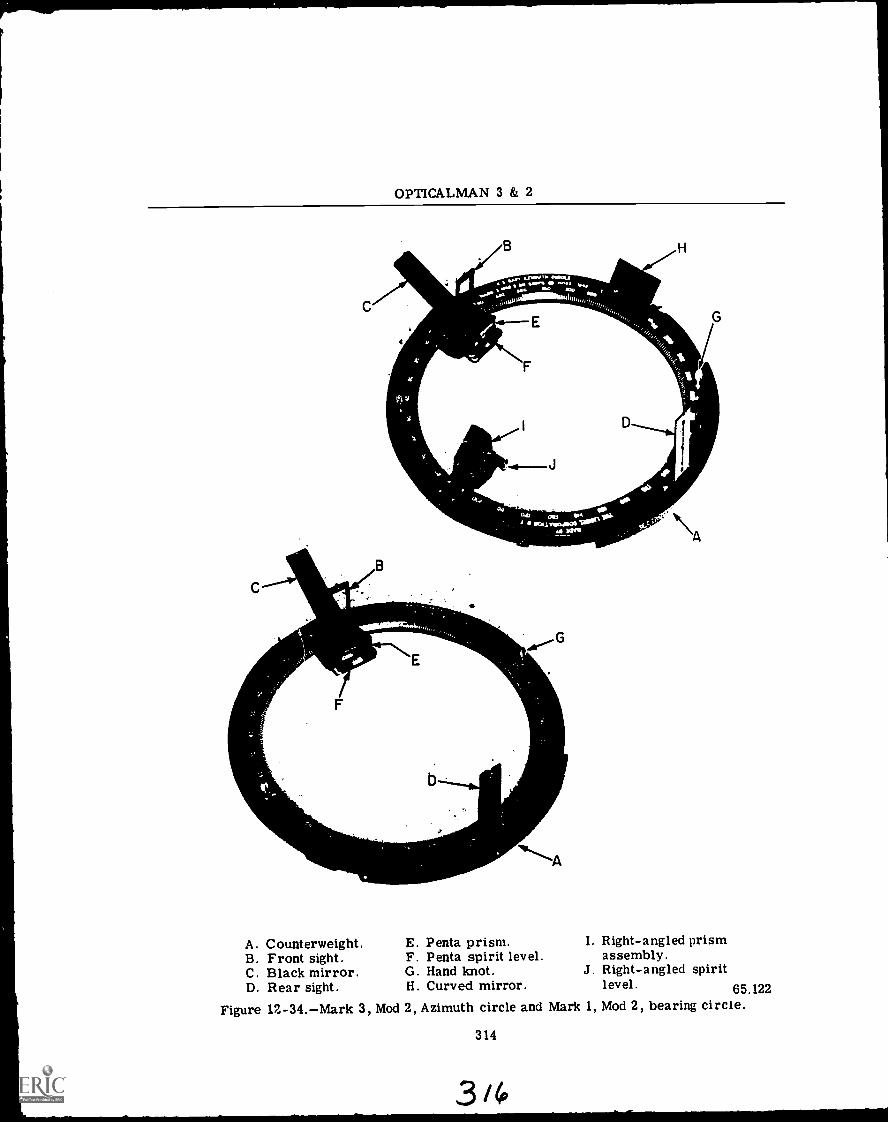
OPTICALMAN 3 & 2
C
A. Counterweight. E. Penta prism. I. Right-angled prismB. Front sight. F. Penta spirit level. assembly.C. Black mirror. G. Hand knot. J. Right-angled spiritD. Rear sight. H. Curved mirror. level. 65.122
Figure 12-34.Mark 3, Mod 2, Azimuth circle and Mark 1, Mod 2, bearing circle.
314
3 i6
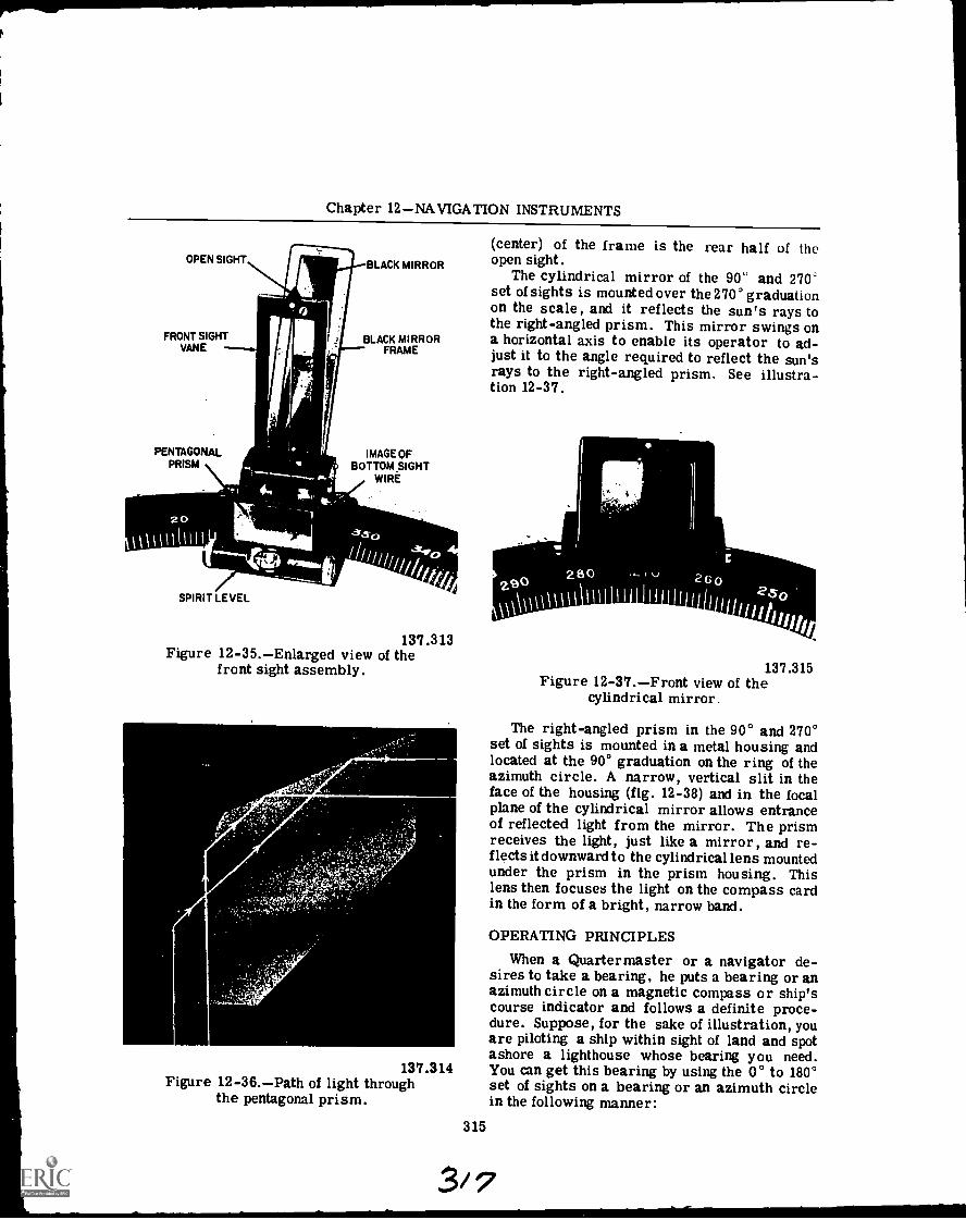
Chapter 12NAVIGATION INSTRUMENTS
OPEN SIGHT
FRONT SIGHTVANE
BLACK MIRROR
BLACK MIRRORFRAME
PENTAGONAL IMAGE QFPRISM BOTTOM _SIGHT
WIRE
t
SPIRIT LEVEL
t Jg
A
137.313Figure 12-35.Enlarged view of the
front sight assembly.
137.314Figure 12-36.Path of light through
the pentagonal prism.
(center) of the frame is the rear half of theopen sight.
The cylindrical mirror of the 90° and 270'set of sights is mounted over the 270' graduationon the scale, and it reflects the sun's rays tothe right-angled prism. This mirror swings ona horizontal axis to enable its operator to ad-just it to the angle required to reflect the sun'srays to the right-angled prism. See illustra-tion 12-37.
315
137.315Figure 12-37.Front view of the
cylindrical mirror.
The right-angled prism in the 90° and 270°set of sights is mounted in a metal housing andlocated at the 90° graduation on the ring of theazimuth circle. A narrow, vertical slit in theface of the housing (fig. 12-38) and in the focalplane of the cylindrical mirror allows entranceof reflected light from the mirror. The prismreceives the light, just like a mirror, and re-flects it downward to the cylindrical lens mountedunder the prism in the prism housing. Thislens then focuses the light on the compass cardin the form of a bright, narrow band.
OPERATING PRINCIPLES
When a Quartermaster or a navigator de-sires to take a bearing, he puts a bearing or anazimuth circle on a magnetic compass or ship'scourse indicator and follows a definite proce-dure. Suppose, for the sake of illustration, youare piloting a ship within sight of land and spotashore a lighthouse whose bearing you need.You can get this bearing by using the 0° to 180°set of sights on a bearing or an azimuth circlein the following manner:
3/7
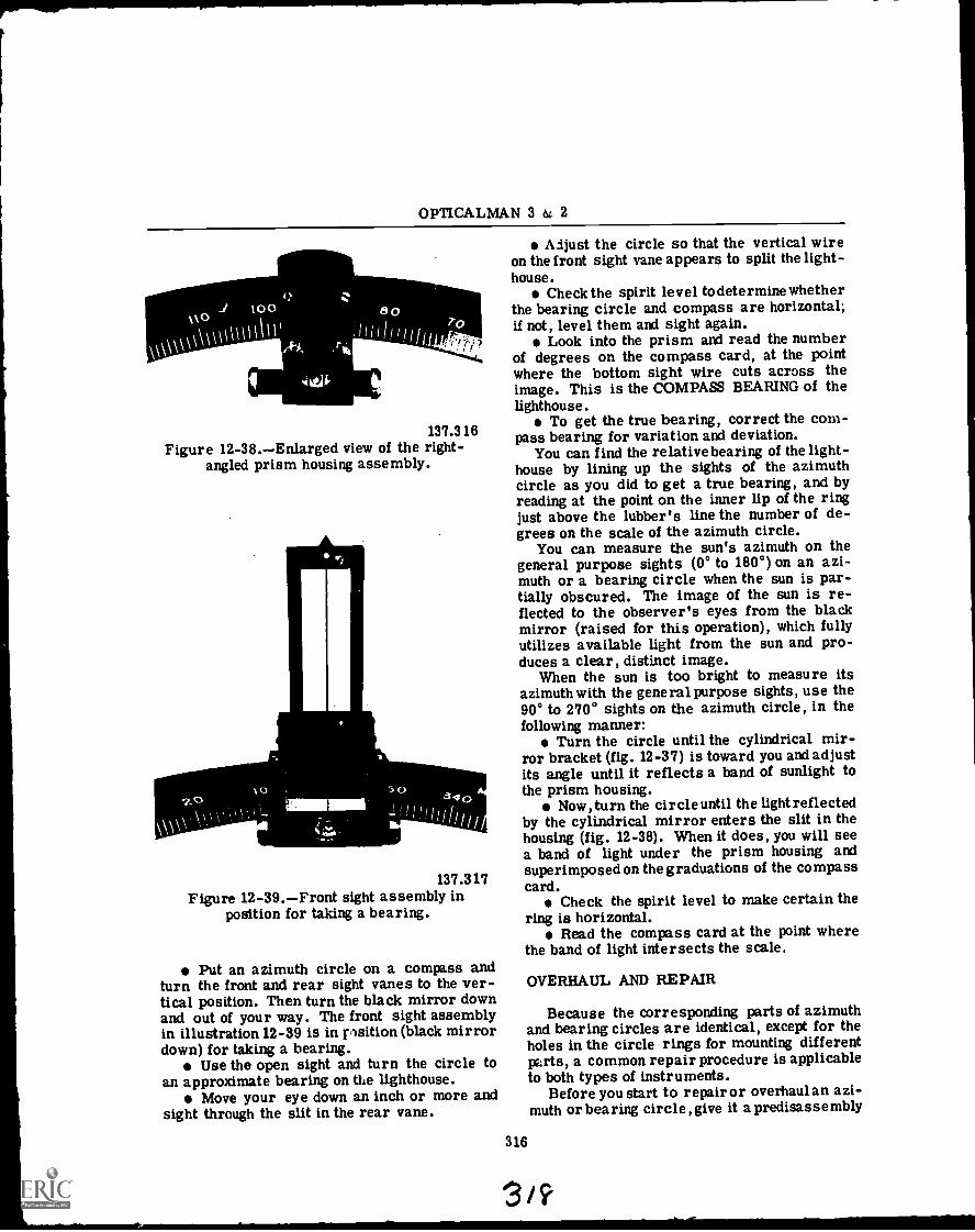
OPTICALMAN 3 & 2
137.316Figure 12-38.Enlarged view of the right-
angled prism housing assembly.
137.317Figure 12-39.Front sight assembly in
position for taking a bearing.
Put an azimuth circle on a compass andturn the front and rear sight vanes to the ver-tical position. Then turn the black mirror downand out of your way. The front sight assemblyin illustration 12-39 is in psition (black mirrordown) for taking a bearing.
Use the open sight and turn the circle toan approximate bearing on the lighthouse.
Move your eye down an inch or more andsight through the slit in the rear vane.
Adjust the circle so that the vertical wireon the front sight vane appears to split the light-house.
Check the spirit level to determine whetherthe bearing circle and compass are horizontal;if not, level them and sight again.
Look into the prism and read the numberof degrees on the compass card, at the pointwhere the bottom sight wire cuts across theimage. This is the COMPASS BEARING of thelighthouse.
To get the true bearing, correct the com-pass bearing for variation and deviation.
You can find the relative bearing of the light-house by lining up the sights of the azimuthcircle as you did to get a true bearing, and byreading at the point on the inner lip of the ringjust above the lubber's line the number of de-grees on the scale of the azimuth circle.
You can measure the sun's azimuth on thegeneral purpose sights (0° to 180°) on an azi-muth or a bearing circle when the sun is par-tially obscured. The image of the sun is re-flected to the observer's eyes from the blackmirror (raised for this operation), which fullyutilizes available light from the sun and pro-duces a clear, distinct image.
When the sun is too bright to measure itsazimuth with the general purpose sights, use the90° to 270° sights on the azimuth circle, in thefollowing manner:
Turn the circle until the cylindrical mir-ror bracket (fig. 12-37) is toward you and adjustits angle until it reflects a band of sunlight tothe prism housing.
Now, turn the circle until the light reflectedby the cylindrical mirror enters the slit in thehousing (fig. 12-38). When it does, you will seea band of light under the prism housing andsuperimposed on the graduations of the compasscard.
Check the spirit level to make certain thering is horizontal.
Read the compass card at the point wherethe band of light intersects the scale.
OVERHAUL AND REPAIR
Because the corresponding parts of azimuthand bearing circles are identical, except for theholes in the circle rings for mounting differentparts, a common repair procedure is applicableto both types of instruments.
Before you start to repair or overhaul an azi-muth or bearing circle, give it a predisassembly
316
3 / ?
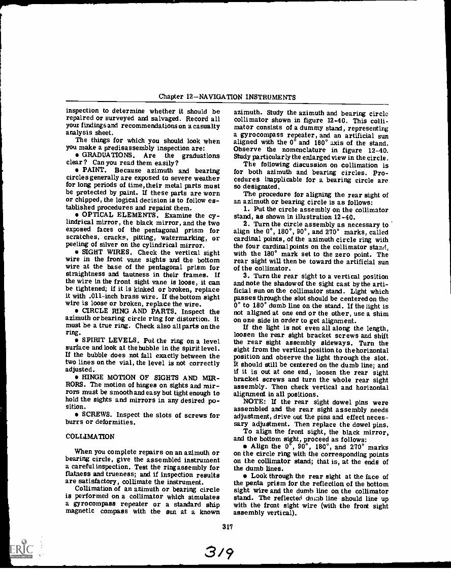
Chapter 12NAVIGATION INSTRUMENTS
inspection to determine whether it should berepaired or surveyed and salvaged. Record allyour findings and recommendations on a casualtyanalysis sheet.
The things for which you should look whenyou make a predisassembly inspection are:
GRADUATIONS. Are the graduationsclear ? Can you read them easily?
PAINT. Because azimuth and bearingcircles generally are exposed to severe weatherfor long periods of time, their metal parts mustbe protected by paint. If these parts are wornor chipped, the logical decision is to follow es-tablished procedures and repaint them.
OPTICAL ELEMENTS. Examine the cy-lindrical mirror, the black mirror, and the twoexposed faces of the pentagonal prism forscratches, cracks, pitting, watermarking, orpeeling of silver on the cylindrical mirror.
SIGHT WIRES. Check the vertical sightwire in the front vane sights and the bottomwire at the base of the pentagonal prism forstraightness and tautness in their frames. Ifthe wire in the front sight vane is loose, it canbe tightened; if it is kinked or broken, replaceit with .011-inch brass wire. If the bottom sightwire is loose or broken, replace the wire.
CIRCLE RING AND PARTS. Inspect theazimuth or bearing circle ring for distortion. Itmust be a true ring. Check also all parts on thering.
SPIRIT LEVELS. Put the ring on a levelsurface and look at the bubble in the spirit level.If the bubble does not fall exactly between thetwo lines on the vial, the level is not correctlyadjusted.
HINGE MOTION OF SIGHTS AND MIR-RORS. The motion of hinges on sights and mir-rors must be smooth and easy but tight enough tohold the sights and mirrors in any desired po-sition.
SCREWS. Inspect the slots of screws forburrs or deformities.
COLLIMATION
When you complete repairs on an azimuth orbearing circle, give the assembled instrumenta careful inspection. Test the ring assembly forflatness and trueness; and if inspection resultsare satisfactory, collimate the instrument.
Collimation of an azimuth or bearing circleis performed on a collimator which simulatesa gyrocompass repeater or a standard shipmagnetic compass with the sun at a known
azimuth. Study the azimuth and bearing circlecollimator shown in figure 12-40. This colli-mator consists of a dummy stand, representinga gyrocompass repeater, and an artificial sunaligned with the 0° and 180° axis of the stand.Observe the nomenclature in figure 12-40.Study particularly the enlarged view in the circle.
The following discussion on collimation isfor both azimuth and bearing circles. Pro-cedures inapplicable for a bearing circle areso designated.
The procedure for aligning the rear sight ofan azimuth or bearing circle is as follows:
1. Put the circle assembly on the collimatorstand, as shown in illustration 12-40.
2. Turn the circle assembly as necessary toalign the 0°, 180°, 90°, and 270° marks, calledcardinal points, of the azimuth circle ring withthe four cardinalpoints on the collimator stand,with the 180° mark set to the zero point. Therear sight will then be toward the artificial sunof the collimator.
3. Turn the rear sight to a vertical positionand note the shadow of the sight cast by the arti-ficial sun on the collimator stand. Light whichpasses through the slot should be centered on the0° to 180° dumb line on the stand. If the light isnot aligned at one end or the other, use a shimon one side in order to get alignment.
If the light is not even all along the length,loosen the rear sight bracket screws and shiftthe rear sight assembly sideways. Turn thesight from the vertical position to the horizontalposition and observe the light through the slot.It should still be centered on the dumb line; andif it is out at one end, loosen the rear sightbracket screws and turn the whole rear sightassembly. Then check vertical and horizontalalignment in all positions.
NOTE: If the rear sight dowel pins wereassembled and the rear sight assembly needsadjustment, drive out the pins and effect neces-sary adjustment. Then replace the dowel pins.
To align the front sight, the black mirror,and the bottom sight, proceed as follows:
Align the 0°, 90°, 180°, and 270° markson the circle ring with the corresponding pointson the collimator stand; that is, at the ends ofthe dumb lines.
Look through the rear sight at the face ofthe penta prism for the reflection of the bottomsight wire and the dumb line on the collimatorstand. The reflected dumb line should line upwith the front sight wire (with the front sightassembly vertical).
317
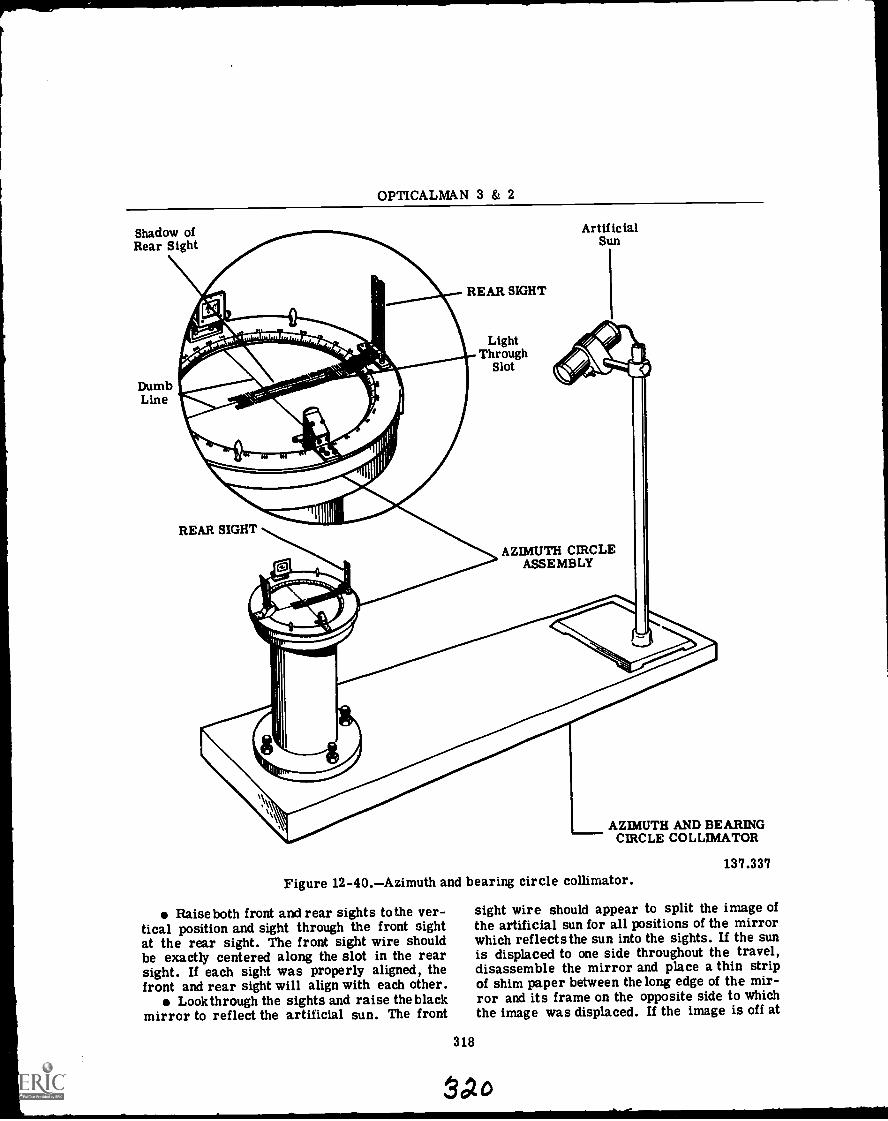
OPTICALMAN 3 & 2
Shadow ofRear Sight
DumbLine
REAR SIGHT
ArtificialSun
LightThrough
Slot
AZIMUTH CIRCLEASSEMBLY
AZIMUTH AND BEARINGCIRCLE COLLIMATOR
Figure 12-40.Azimuth and bearing circle collimator.
Raise both front and rear sights to the ver-tical position and sight through the front sightat the rear sight. The front sight wire shouldbe exactly centered along the slot in the rearsight. If each sight was properly aligned, thefront and rear sight will align with each other.
Look through the sights and raise the blackmirror to reflect the artificial sun. The front
318
137.337
sight wire should appear to split the image ofthe artificial sun for all positions of the mirrorwhich reflects the sun into the sights. If the sunis displaced to one side throughout the travel,disassemble the mirror and place a thin stripof shim paper between the long edge of the mir-ror and its frame on the opposite side to whichthe image was displaced. If the image is off at
Sao
Chapter 12NAVIGATION INSTRUMENTS
one end of the mirror only, shim the oppositecorner across from the direction of displace-ment.
Look through the rear sight into the faceof the penta prism at the image of the bottomsight wire and the 0° to 180° dumb line on thecollimator stand. The bottom sight wire shouldcoincide with the dumb line; and if it does not,shift the bottom sight assembly as required tobring the bottom sight wire into coincidence withthe dumb line.
To level the penta spirit level, do the fol-lowing:
1. Since the collimator stand is level, thebubble in the spirit level should be centered be-tween the leveling lines on the level. To makea SMALL adjustment, loosen the penta levelmounting screws and adjust the spirit level as-sembly as necessary to center the bubble. Whena GREATER AMOUNT of adjustment is neces-sary to center the bubble, remove the spiritlevel caps and shim the level with cotton waddingand paper liner.
At this point, a MK 1, Mod 3, bearing circleis completely aligned. The next step in colli-mation for this instrument is 'Dowelling theFront and Rear Sights," which is explained later.For a Mk 3, Mod 3, azimuth circle you mustcollimate the azimuth elements.
The procedure for aligning the cylindricalmirror and the right-angled prism follows:
Turn the azimuth circle assembly to bring theface of the cylindrical mirror toward the arti-ficial sun. The 90° and 270° marks on the azi-muth circle ring must be aligned with the 0° and180° dumb line on the collimator stand. The 90°mark should be set at the 0° end of the dumb line.
The right-angled spirit level bubble shouldbe centered between the two leveling lines onthe level. Make small adjustments by looseningthe right-angled level mounting screws and shift-ing the right-angled spirit level assembly. Forlarger adjustments, remove the two spirit levelcaps and shim the right-angled spirit level.
This last step completes the collimation pro-cedure for a Mk 3, Mod 3, azimuth circle.
The front sight, mirror, prism and level as-sembly, and the rear sight assembly must bedowelled to an azimuth or bearing circle ring.To do this, proceed in the following manner:
If the sights need realignment, the originalholes for the dowel pins may be slightly mis-placed. When this is the case, use a taperedbottom reamer to enlarge and form a straighttapered hole and install a tapered dowel pin.
If a new azimuth or bearing circle ringwas assembled, use the original holes in therear sight bracket and the penta prism box.With a .086-inch drill, drill holes 1/8-inch deepin the azimuth or bearing circle. Then assem-ble the rear and front sight dowel pins.
If you must use a new rear sight bracket orpenta prism box, plug the original holes and usean .086-inch drill to make new holes 1/8-inchdeep in the ring and assemble the front and rearsight dowel pins.
After you collimate an azimuth or bearingcircle, give it a final inspection to make certaineverything concerning repair and adjustment ofthe instrument is satisfactory. Inspect as fol-lows:
Check the circle for completeness of parts.Inspect the general appearance, finish of
parts, tightness in the assembly, legibility ofengravings, and tightness of screws.
Examine optical parts for defects andcleanliness.
Inspect the pivot tension of the front andrear sight vanes, and the black and cylindricalmirror assemblies.
Make final notations (if any) on the casualtyanalysis sheet for the instrument and put it intho. case.
SEXTANT
A sextant is an instrument used for measur-ing the angle between two objects. The arc onwhich the scale for reading angles is engravedis approximately one-sixth of a circle; hencethe name of the instrument, SEXTANT.
When a ship is at sea and away from visiblelandmarks, the navigator must use celestialnavigation to determine his ship's position.Celestial navigation is possible because thenavigator can use a sextant to determine theangle which the sun or another celestial bodymakes with the visible horizon. He can thendetermine the position of the particular celestialbody at the time he took the sight by referringto the NAUTICAL ALMANAC. If he knows theposition of the celestial body at the TIME OFSIGHT and the angle it makes with the horizon,he can (after applying certain correction fac-tors) ascertain the exact position of his ship.
A sextant is well adapted for measuringangles at sea for three reasons:
1. It is small, light, and can be held easilyin one hand.
2. It does not need a stable mounting.
319
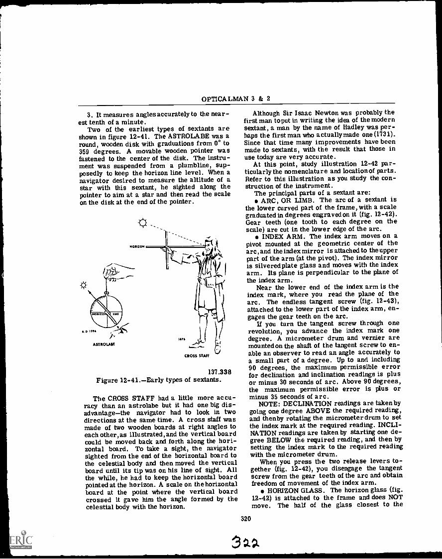
OPTICALMAN 3 & 2
3. It measures angles accurately to the near-est tenth of a minute.
Two of the earliest types of sextants areshown in figure 12-41. The ASTROLABE was around, wooden disk with graduations from 00 to359 degrees. A movable wooden pointer wasfastened to the center of the disk. The instru-ment was suspended from a plumbline, sup-posedly to keep the horizon line level. When anavigator desired to measure the altitude of astar with this sextant, he sighted along thepointer to aim at a star and then read the scaleon the disk at the end of the pointer.
HORIZON
137.338Figure 12-41.Early types of sextants.
The CROSS STAFF had a little more accu-racy than an astrolabe but it had one big dis-advantagethe navigator had to look in twodirections at the same time. A cross staff wasmade of two wooden boards at right angles toeach other, as illustrated, and the vertical boardcould be moved back and forth along the hori-zontal board. To take a sight, the navigatorsighted from the end of the horizontal board tothe celestial body and then moved the verticalboard until its tip was on his line of sight. Allthe while, he had to keep the horizontal boardpointed at the horizon. A scale on the horizontalboard at the point where the vertical boardcrossed it gave him the angle formed by thecelestial body with the horizon.
Although Sir Isaac Newton was probably thefirst man toput in writing the idea of the modernsextant, a man by the name of Hadley was per-haps the first man who actually made one (1731).Since that time many improvements have beenmade to sextants, with the result that those inuse today are very accurate.
At this point, study illustration 12-42 par-ticularly the nomenclature and locationof parts.Refer to this illustration as you study the con-struction of the instrument.
The principal parts of a sextant are:ARC, OR LIMB. The arc of a sextant is
the lower curved part of the frame, with a scalegraduated in degrees engraved on it (fig. 12-42).Gear teeth (one tooth to each degree on thescale) are cut in the lower edge of the arc.
INDEX ARM. The index arm moves on apivot mounted at the geometric center of thearc, and the index mirror is attached to the upperpart of the arm (at the pivot). The index mirroris silvered plate glass and moves with the indexarm. Its plane is perpendicular to the plane ofthe index arm.
Near the lower end of the index arm is theindex mark, where you read the plane of thearc. The endless tangent screw (fig. 12-43),attached to the lower part of the index arm, en-gages the gear teeth on the arc.
If you turn the tangent screw through onerevolution, you advance the index mark onedegree. A micrometer drum and vernier aremounted on the shaft of the tangent screw to en-able an observer to read an angle accurately toa small part of a degree. Up to and including90 degrees, the maximum permissible errorfor declination and inclination readings is plusor minus 30 seconds of arc. Above 90 degrees,the maximum permissible error is plus orminus 35 seconds of arc.
NOTE: DECLINATION readings are takenbygoing one degree ABOVE the required reading,and thenby rotating the micrometer drum to setthe index mark at the required reading. INCLI-NATION readings are taken by starting one de-gree BELOW the required reading, and then bysetting the index mark to the required readingwith the micrometer drum.
When you press the two release levers to-gether (fig. 12-42), you disengage the tangentscrew from the gear teeth of the arc and obtainfreedom of movement of the index arm.
HORIZON GLASS. The horizon glass (fig.12-42) is attached to the frame and does NOTmove. The half of the glass closest to the
320
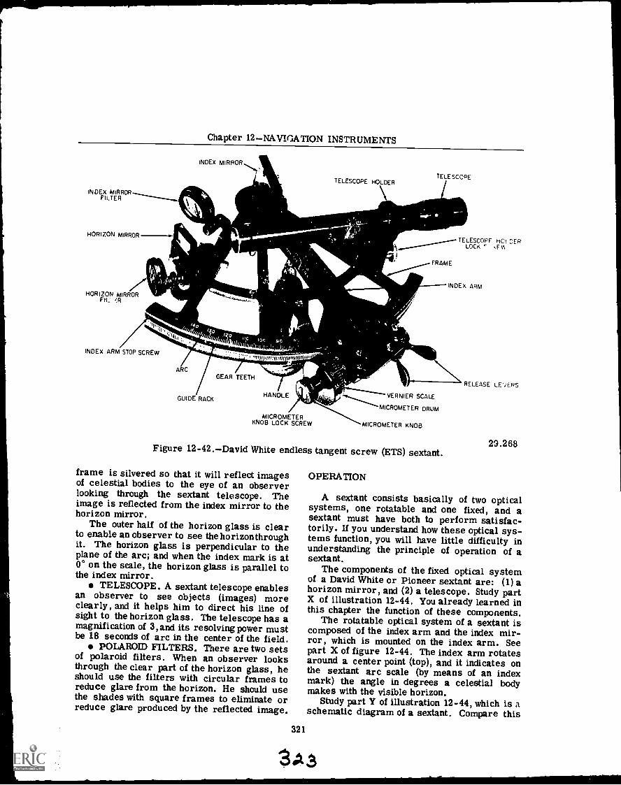
Chapter 12NAVIGATION INSTRUMENTS
INDEX MIRRORFILTER
HORIZON MIRROR ,INDEX MIRROR
HORIZON MIRRORFIL
Alkh_
1110
INDEX ARM STOP SCREW
ARC
GUIDE RACK
6,1
' gmstgrs trentllogoo
GEAR TEETH
TELESCOPE HOLDER
yam_HANDLE
MICROMETERKNOB LOCK SCREW
11
TELESCOPE
TELESCOPE HO; DERLOCK ,Fri
FRAME
INDEX ARM
VERNIER SCALE
MICROMETER DRUM
MICROMETER KNOB
Figure 12-42.David White endless tangent screw (ETS) sextant.
frame is silvered so that it will reflect imagesof celestial bodies to the eye of an observerlooking through the sextant telescope. Theimage is reflected from the index mirror to thehorizon mirror.
The outer half of the horizon glass is clearto enable an observer to see the horizonthroughit. The horizon glass is perpendicular to theplane of the arc; and when the index mark is at0° on the scale, the horizon glass is parallel tothe index mirror.
TELESCOPE. A sextant telescope enablesan observer to see objects (images) moreclearly, and it helps him to direct his line ofsight to the horizon glass. The telescope has amagnification of 3, and its resolving power mustbe 18 seconds of arc in the center of the field.
POLAROID FILTERS. There are two setsof polaroid filters. When an observer looksthrough the clear part of the horizon glass, heshould use the filters with circular frames toreduce glare from the horizon. He should usethe shades with square frames to eliminate orreduce glare produced by the reflected image.
OPERATION
RELEASE LE'vERS
29.268
A sextant consists basically of two opticalsystems, one rotatable and one fixed, and asextant must have both to perform satisfac-torily. If you understand how these optical sys-tems function, you will have little difficulty inunderstanding the principle of operation of asextant.
The components of the fixed optical systemof a David White or Pioneer sextant are: (1) ahorizon mirror, and (2) a telescope. Study partX of illustration 12-44. You already learned inthis chapter the function of these components.
The rotatable optical system of a sextant iscomposed of the index arm and the index mir-ror, which is mounted on the index arm. Seepart X of figure 12-44. The index arm rotatesaround a center point (top), and it indicates onthe sextant arc scale (by means of an indexmark) the angle in degrees a celestial bodymakes with the visible horizon.
Study part Y of illustration 12-44, which is aschematic diagram of a sextant. Compare this
321
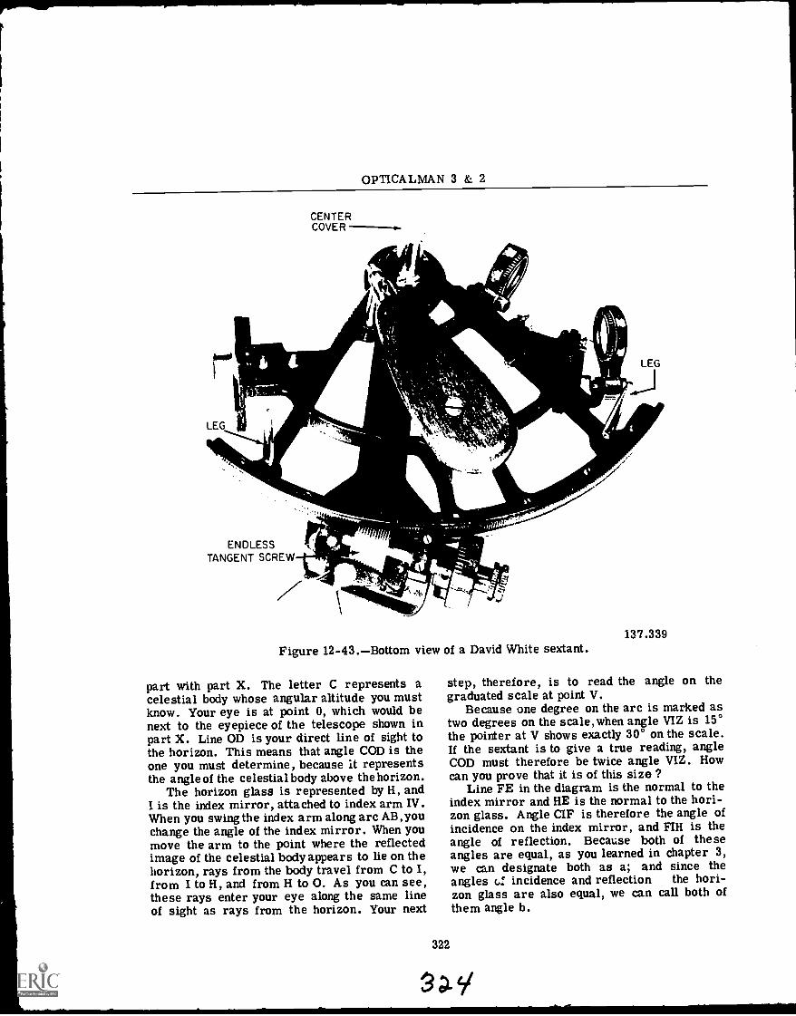
OPTICALMAN 3 & 2
LEG 11--
ENDLESSTANGENT SCREW
CENTERCOVER
1-11111..._
\"41111114ygri--14-,
Figure 12-43.Bottom view of a David White sextant.
part with part X. The letter C represents acelestial body whose angular altitude you mustknow. Your eye is at point 0, which would benext to the eyepiece of the telescope shown inpart X. Line OD is your direct line of sight tothe horizon. This means that angle COD is theone you must determine, because it representsthe angle of the celestial body above the horizon.
The horizon glass is represented by H, andI is the index mirror, attached to index arm IV.When you swing the index arm along arc AB, youchange the angle of the index mirror. When youmove the arm to the point where the reflectedimage of the celestial body appears to lie on thehorizon, rays from the body travel from C to I,from I to H, and from H to 0. As you can see,these rays enter your eye along the same lineof sight as rays from the horizon. Your next
322
LEG
137.339
step, therefore, is to read the angle on thegraduated scale at point V.
Because one degree on the arc is marked astwo degrees on the scale,when angle VIZ is 15°the pointer at V shows exactly 30° on the scale.If the sextant is to give a true reading, angleCOD must therefore be twice angle VIZ. Howcan you prove that it is of this size ?
Line FE in the diagram is the normal to theindex mirror and HE is the normal to the hori-zon glass. Angle CIF is therefore the angle ofincidence on the index mirror, and FIH is theangle of reflection. Because both of theseangles are equal, as you learned in chapter 3,we can designate both as a; and since theangles c.! incidence and reflection the hori-zon glass are also equal, we can call both ofthem angle b.
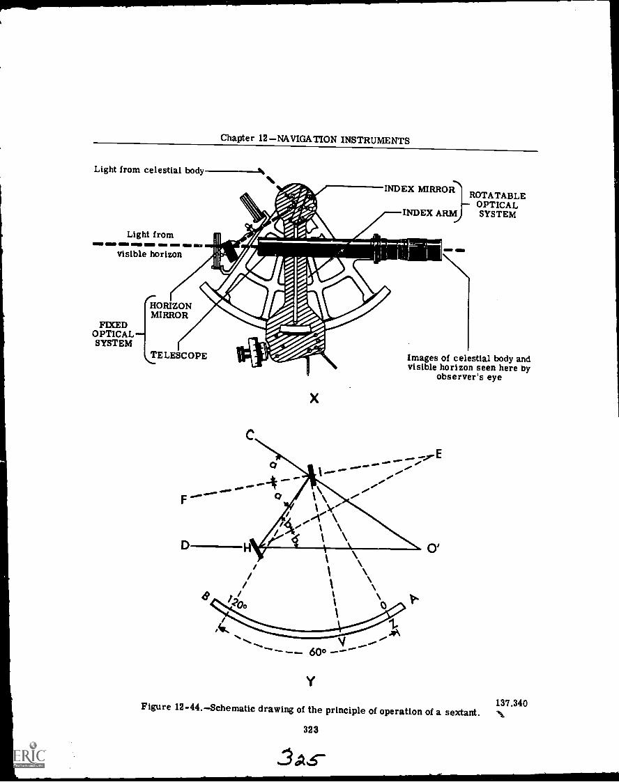
Chapter 12NAVIGATION INSTRUMENTS
Light from celestial body ---k
Light from
visible horizon
HORIZONMIRROR
INDEX MIRRORROTATABLE
OPTICALINDEX ARM SYSTEM
FIXEDOPTICALSYSTEM
`TELESCOPE
D
x
Images of celestial body andvisible horizon seen here by
observer's eye
Y
Figure 12-44.Schematic drawing of the principle of operation of a sextant.
323
137.340
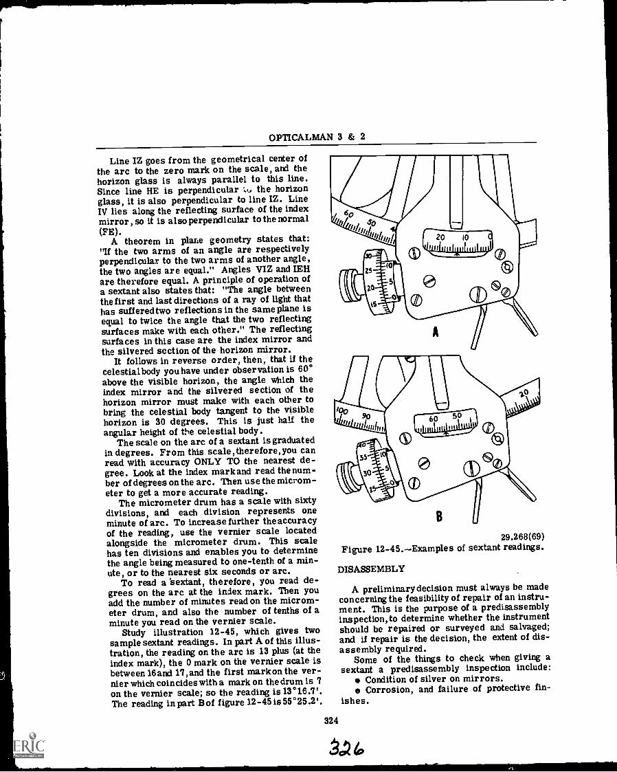
OPTICALMAN 3 & 2
Line IZ goes from the geometrical center ofthe arc to the zero mark on the scale, and thehorizon glass is always parallel to this line.Since line HE is perpendicular '0, the horizonglass, it is also perpendicular to line IZ. LineIV lies along the reflecting surface of the indexmirror, so it is also perpendicular to the normal(FE).
A theorem in plane geometry states that:If the two arms of an angle are respectivelyperpendicular to the two arms of another angle,the two angles are equal." Angles VIZ and IEHare therefore equal. A principle of operation ofa sextant also states that: "The angle betweenthe first and last directions of a ray of light thathas suffered two reflections in the same plane isequal to twice the angle that the two reflectingsurfaces make with each other." The reflectingsurfaces in this case are the index mirror andthe silvered section of the horizon mirror.
It follows in reverse order, then, that if thecelestial body you have under observation is 60°above the visible horizon, the angle which theindex mirror and the silvered section of thehorizon mirror must make with each other tobring the celestial body tangent to the visiblehorizon is 30 degrees. This is just half theangular height of the celestial body.
The scale on the arc of a sextant is graduatedin degrees. From this scale, therefore, you canread with accuracy ONLY TO the nearest de-gree. Look at the index mark and read the num-ber of degrees on the arc. Then use the microm-eter to get a more accurate reading.
The micrometer drum has a scale with sixtydivisions, and each division represents oneminute of arc. To increase further theaccuracyof the reading, use the vernier scale locatedalongside the micrometer drum. This scalehas ten divisions and enables you to determinethe angle being measured to one-tenth of a min-ute, or to the nearest six seconds or arc.
To read a 'sextant, therefore, you read de-grees on the arc at the index mark. Then youadd the number of minutes read on the microm-eter drum, and also the number of tenths of aminute you read on the vernier scale.
Study illustration 12-45, which gives twosample sextant readings. In part A of this illus-tration, the reading on the arc is 13 plus (at theindex mark), the 0 mark on the vernier scale isbetween 16 and 17, and the first mark on the ver-nier which coincides with a mark on the drum is 7on the vernier scale; so the reading is 13°16.7'.The reading in part B of figure 12-45 is 55°25.2'.
29.268(69)Figure 12-45.Examples of sextant readings.
DISASSEMBLY
A preliminary decision must always be madeconcerning the feasibility of repair of an instru-ment. This is the purpose of a predisassemblyinspection, to determine whether the instrumentshould be repaired or surveyed and salvaged;and if repair is the decision, the extent of dis-assembly required.
Some of the things to check when giving asextant a predisassembly inspection include:
Condition of silver on mirrors.Corrosion, and failure of protective fin-
ishes.
324
AP
Chapter 12NAVIGATION INSTRUMENTS
Evidence of unauthorized tampering anddisassembly.
Appearance, finish, and condition of partsin the sextant assembly. Examine scale mark-ings for legibility.
Cleanliness and physical condition of thetelescope assembly. If mounted, remove thetelescope from its sliding bracket before youmake this test.
NOTE: Be certain the diopter scale refer-ence mark is at the top when you mount thesextant telescope in the sliding bracket.
Action of the diopter focusing ring. Itshould be smooth over the entire diopter scalerange, but it should be fairly tight.
Polaroid filter assemblies. There shouldbe no cracks or chips, cloudiness, or dark spotscaused by dirt or moisture between the indi-vidual glasses of each filter.
NOTE: Polaroid filters must have a protec-tive coating on their edges.
Rack teeth. Check with an eye loupe forwear, bends, and chipping. Clean the rackteeth, the endless tangent worm and worm gearthread, and the guide slot with a suction line ora nylon brush.
The actual disassembly of the sextant shouldnot be undertaken without using Nav Ships Man-ual 250-624 -12 as a technical guide. This manualgives step by step procedures for disassembly,overhaul, reassembly and Collimation of thesextant.
OVERHAUL AND REPAIR
All overhaul and repair steps should be ac-complished exactly as prescribed in the Nav-Ships Technical Manual. If a problem arisesthat you are in doubt about, seek the advice ofyour shop supervisor.
During the predisassembly inspection of thesextant you made recommendations concerningsome parts on the casualty analysis sheet forthe instrument. After disassembly, inspect alldisassembled parts and make a decision con-cerning their usability. If they are still good,clean them in the approved manner and protectthem until needed. Put parts which can be re-paired in a special tray; discard parts whichhave no further usefulness.
A sextant's accuracy is dependent upon ac-curate engagement of the endless tangent wormin th3 sextant rack teeth. Nicks or burrs onthe rack teeth, or high spots on the worm
gear thread, will cause large errors in read-ings.
The technical manual for sextants lists andillustrates several special tools that are re-quired for work on sextants. Always use thesetools as they are designed to perform a definitefunction that will help you to accomplish yourjob in an efficient manner and help prevent dam-age to parts during repair operations.
REASSEMBLY AND COLLIMATION
After repairs have been made and the sextanthas been assembled in the approved manner,give it a precollimation inspection. Ensure thatall repairs have been accomplished and thereare no defects that would prevent you from ac-curately collimating the sextant.
The collimation procedure outlined in thetechnical manual must be followed in precisedetail in order for the sextant to meet perform-ance standards of the instrument. During colli-mation, handle the sextant very carefully, asrough treatment will often cause a misalign-ment that will prevent proper collimation. Thesextant is a delicate instrument and should al-ways be given careful treatment. Make it a habitto observe these rules:
Handle the sextant carefully. Don't let itget bumped or jolted.
When you aren't actually using it or re-pairing it, keep it in its box.
Never leave a sextant where it's exposedto moisture, or to the direct rays of the sun.
Before you pick up a sextant box, be CER-TAIN that the locking levers are secured overthe sextant handle, the telescope, and the screwdrivers, and that the lid of the box is closed andthe catch securely fastened.
325
STADIMETER
A stadimeter is an instrument used to meas-ure the range of objects of known height. Aboardship, the officer of the deck uses a stadimeterto maintain his position in a formation by sight-ing on the guide shipfor range. The height scaleis calibrated in feet for objects from 50 to 200feet in height. The range scale is calibrated inyards for readings from 200 to 10,000 yards andinfinity.
Refer to illustrations 12-46 and 12-47 as youstudy the construction of a Fiske stadimeter, theprincipal parts of which are:
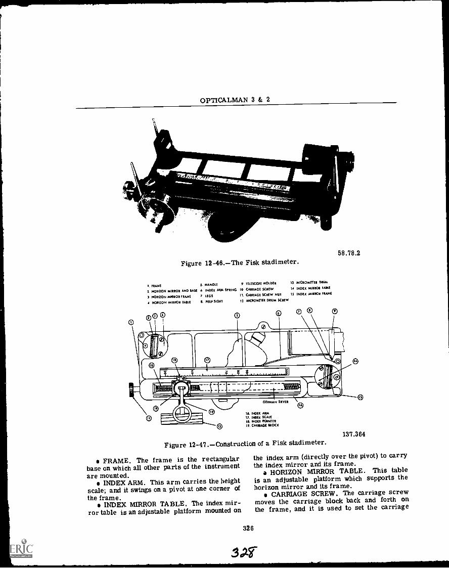
OPTICALMAN 3 & 2
\M 'PP"*M M --1? /'
V
'
Figure 12-46.The Fisk stadimeter.
111.1144.--.
I. FRAME S HANDLE 9. TELESCOPE HOLDER 13. MICROMETER DRUM
2. HORIZON MIRROR AND SASE 6. INDEX ARM SPRING 10 CARRIAGE SCREW 14 INDEX MIRROR MILE
3 HORIZON MIRROR FRAME 7. LEGS
4 HORIZON MIRROR TARIE E PEEP SIGHT
CARRIAGE SCREW NUT IS INDEX MIRROR FRAME
13. MICROMETER DRUM SCREW
58.78.2
GERMAN SILVER
I& INDEX ARM17. mix SCALE
1$. INDEX POINTER19. CARRIAGE HOCK
Figure 12-47.Construction of a Fisk stadimeter.
FRAME. The frame is the rectangularbase on which all other parts of the instrumentare mounted.
INDEX ARM. This arm carries the heightscale; and it swings on a pivot at one corner of
the frame.INDEX MIRROR TABLE. The index mir-
ror table is an adjustable platform mounted on
326
137.364
the index arm (directly over the pivot) to carrythe index mirror and its frame.
a HORIZON MIRROR TABLE. This tableis an adjustable platform which supports thehorizon mirror and its frame.
CARRIAGE SCREW. The carriage screwmoves the carriage block back and forth onthe frame, and it is used to set the carriage
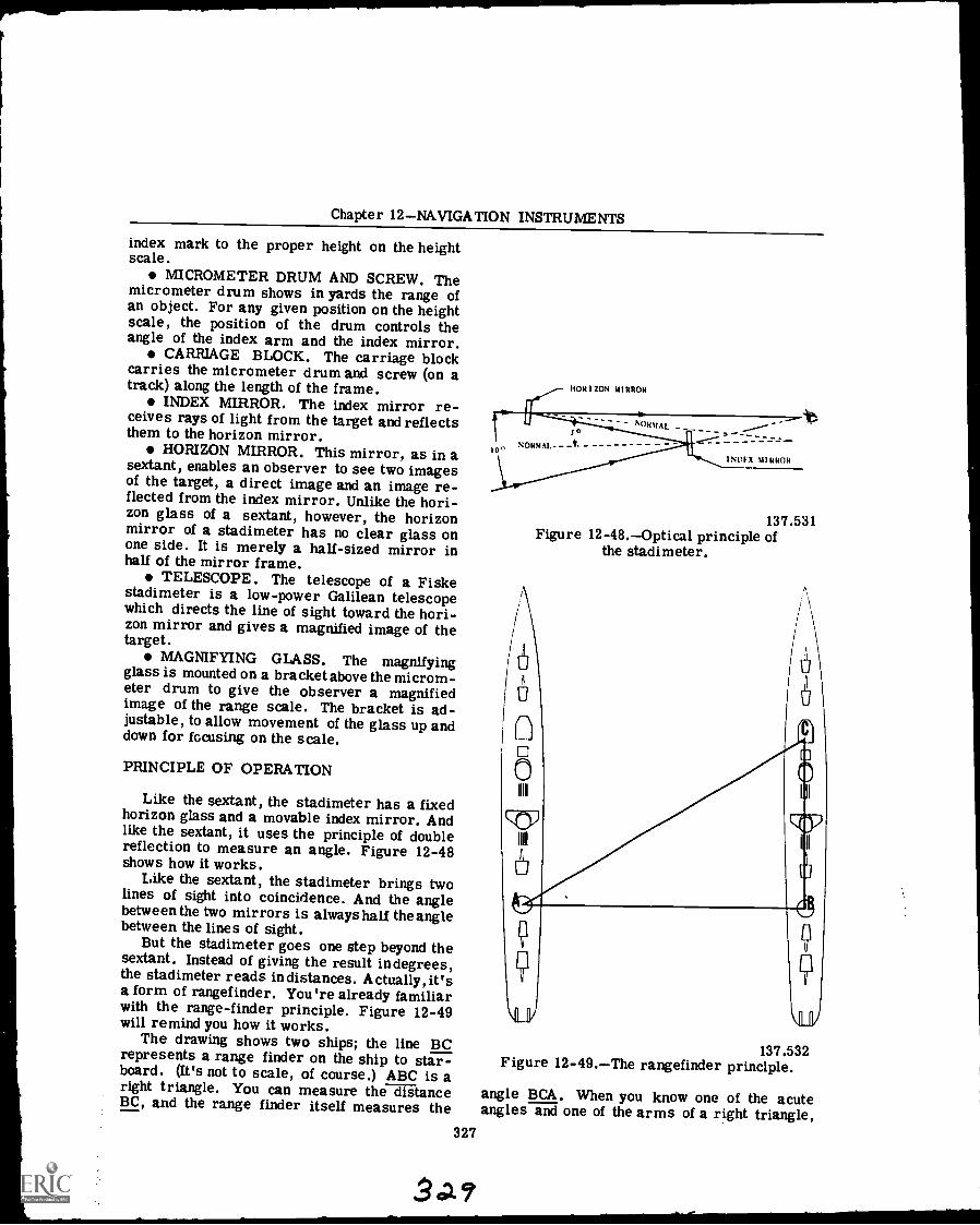
Chapter 12NAVIGATION INSTRUMENTS
index mark to the proper height on the heightscale.
MICROMETER DRUM AND SCREW. Themicrometer drum shows in yards the range ofan object. For any given position on the heightscale, the position of the drum controls theangle of the index arm and the index mirror.
CARRIAGE BLOCK. The carriage blockcarries the micrometer drum and screw (on atrack) along the length of the frame.
INDEX MIRROR. The index mirror re-ceives rays of light from the target and reflectsthem to the horizon mirror.
HORIZON MIRROR. This mirror, as in asextant, enables an observer to see two imagesof the target, a direct image and an image re-flected from the index mirror. Unlike the hori-zon glass of a sextant, however, the horizonmirror of a stadimeter has no clear glass onone side. It is merely a half-sized mirror inhalf of the mirror frame.
TELESCOPE. The telescope of a Fiskestadimeter is a low-power Galilean telescopewhich directs the line of sight toward the hori-zon mirror and gives a magnified image of thetarget.
MAGNIFYING GLASS. The magnifyingglass is mounted on a bracket above the microm-eter drum to give the observer a magnifiedimage of the range scale. The bracket is ad-justable, to allow movement of the glass up anddown for focusing on the scale.
PRINCIPLE OF OPERATION
Like the sextant, the stadimeter has a fixedhorizon glass and a movable index mirror. Andlike the sextant, it uses the principle of doublereflection to measure an angle. Figure 12-48shows how it works.
Like the sextant, the stadimeter brings twolines of sight into coincidence. And the anglebetween the two mirrors is always half the anglebetween the lines of sight.
But the stadimeter goes one step beyond thesextant. Instead of giving the result indegrees,the stadimeter reads indistances. Actually, it'sa form of rangefinder. You're already familiarwith the range-finder principle. Figure 12-49will remind you how it works.
The drawing shows two ships; the line BCrepresents a range finder on the ship to star-board. (It's not to scale, of course.) ABC is aright triangle. You can measure the distanceBC, and the range finder itself measures the
327
HORIZON MIRROR
S
10^ NORMAL
I NOF X MIRROR
137.531Figure 12-48.Optical principle of
the stadimeter.
137.532Figure 12-49.The rangefinder principle.
angle BCA. When you know one of the acuteangles and one of the arms of a right triangle,
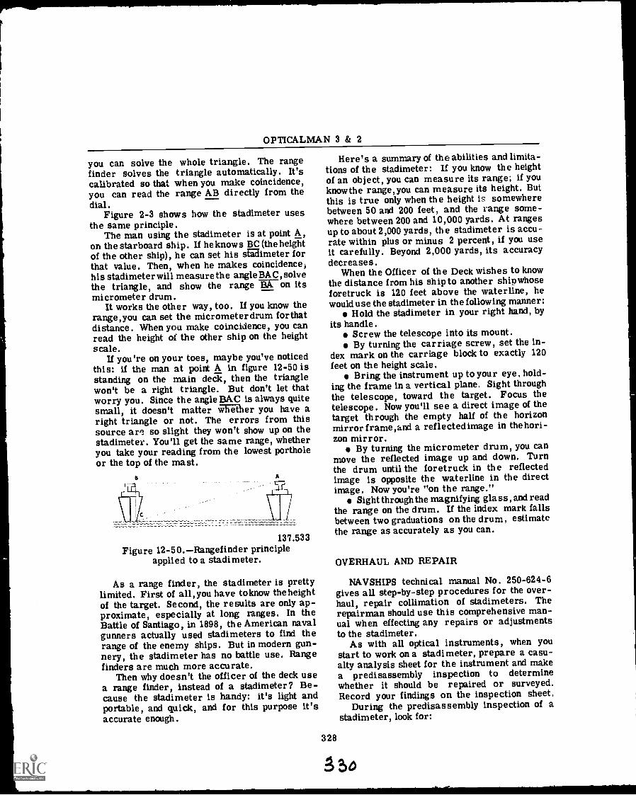
OPTICALMAN 3 & 2
you can solve the whole triangle. The rangefinder solves the triangle automatically. It'scalibrated so that when you make coincidence,you can read the range AB directly from thedial.
Figure 2-3 shows how the stadimeter usesthe same principle.
The man using the stadimeter is at point A,on the starboard ship. If he knows BC (the heightof the other ship), he can set his stadimeter forthat value. Then, when he makes coincidence,his stadimeter will measure the angle BAC, solvethe triangle, and show the range on itsmicrometer drum.
It works the other way, too. If you know therange,you can set the micrometerdrum forthatdistance. When you make coincidence, you canread the height of the other ship on the heightscale.
If you're on your toes, maybe you've noticedthis: if the man at point A in figure 12-50 isstanding on the main deck, then the trianglewon't be a right triangle. But don't let thatworry you. Since the angle BAC is always quitesmall, it doesn't matter whether you have aright triangle or not. The errors from thissource are so slight they won't show up on thestadimeter. You'll get the same range, whetheryou take your reading from the lowest portholeor the top of the mast.
B A
137.533Figure 12-50.Rangefinder principle
applied to a stadimeter.
As a range finder, the stadimeter is prettylimited. First of all, you have to know the heightof the target. Second, the results are only ap-proximate, especially at long ranges. In theBattle of Santiago, in 1898, the American navalgunners actually used stadimeters to find therange of the enemy ships. But in modern gun-nery, the stadimeter has no battle use. Rangefinders are much more accurate.
Then why doesn't the officer of the deck usea range finder, instead of a stadimeter? Be-cause the stadimeter is handy: it's light andportable, and quick, and for this purpose it'saccurate enough.
Here's a summary of the abilities and limita-tions of the stadimeter: If you know the heightof an object, you can measure its range; if youknowthe range,you can measure its height. Butthis is true only when the height is somewherebetween 50 and 200 feet, and the range some-where between 200 and 10,000 yards. At rangesup to about 2,000 yards, the stadimeter is accu-rate within plus or minus 2 percent, if you useit carefully. Beyond 2,000 yards, its accuracydecreases.
When the Officer of the Deck wishes to knowthe distance from his ship to another shipwhoseforetruck is 120 feet above the waterline, hewould use the stadimeter in the following manner:
Hold the stadimeter in your right hand, byits handle.
Screw the telescope into its mount.By turning the carriage screw, set the in-
dex mark on the carriage block to exactly 120feet on the height scale.
Bring the instrument up to your eye, hold-ing the frame in a vertical plane. Sight throughthe telescope, toward the target. Focus thetelescope. Now you'll see a direct image of thetarget through the empty half of the horizonmirror frame,and a reflectedimage in the hori-zon mirror.
By turning the micrometer drum, you canmove the reflected image up and down. Turnthe drum until the foretruck in the reflectedimage is opposite the waterline in the directimage. Now you're "on the range."
Sight through the magnifying glass, and readthe range on the drum. If the index mark fallsbetween two graduations on the drum, estimatethe range as accurately as you can.
328
OVERHAUL AND REPAIR
NAVSHIPS technical manual No. 250-624-6gives all step-by-step procedures for the over-haul, repair collimation of stadimeters. Therepairman should use this comprehensive man-ual when effecting any repairs or adjustmentsto the stadimeter.
As with all optical instruments, when youstart to work on a stadimeter, prepare a casu-alty analysis sheet for the instrument and makea predisassembly inspection to determinewhether it should be repaired or surveyed.Record your findings on the inspection sheet.
During the predisassembly inspection of astadimeter, look for:
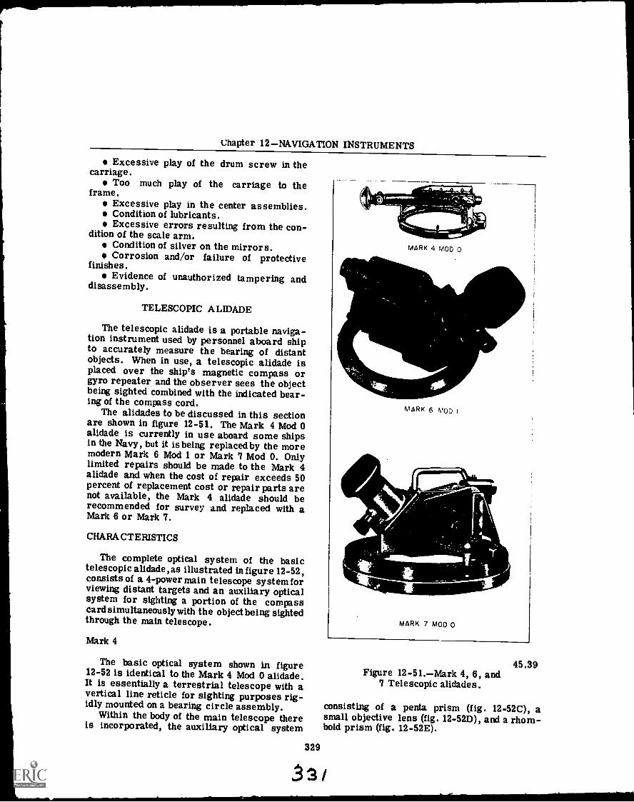
Chapter 12NAVIGATION INSTRUMENTS
Excessive play of the drum screw in thecarriage.
Too much play of the carriage to theframe.
Excessive play in the center assemblies.Condition of lubricants.Excessive errors resulting from the con-
dition of the scale arm.Condition of silver on the mirrors.Corrosion and/or failure of protective
finishes.Evidence of unauthorized tampering and
disassembly.
TELESCOPIC ALIDADE
The telescopic alidade is a portable naviga-tion instrument used by personnel aboard shipto accurately measure the bearing of distantobjects. When in use, a telescopic alidade isplaced over the ship's magnetic compass orgyro repeater and the observer sees the objectbeing sighted combined with the indicated bear-ing of the compass cord.
The alidades to be discussed in this sectionare shown in figure 12-51. The Mark 4 Mod 0alidade is currently in use aboard some shipsin the Navy, but it is being replaced by the moremodern Mark 6 Mod 1 or Mark 7 Mod 0. Onlylimited repairs should be made to the Mark 4alidade and when the cost of repair exceeds 50percent of replacement cost or repair parts arenot available, the Mark 4 alidade should berecommended for survey and replaced with aMark 6 or Mark 7.
CHARACTERISTICS
The complete optical system of the basictelescopic alidade , as illustrated in figure 12 -52,consists of a 4-power main telescope system forviewing distant targets and an auxiliary opticalsystem for sighting a portion of the compasscard simultaneously with the object being sightedthrough the main telescope.
Mark 4
The basic optical system shown in figure12-52 is identical to the Mark 4 Mod 0 alidade.It is essentially a terrestrial telescope with avertical line reticle for sighting purposes rig-idly mounted on a bearing circle assembly.
Within the body of the main telescope thereis incorporated, the auxiliary optical system
329
AlbernAlMARK 4 MOD 0
MARK 6 MOD I
MARK 7 MOD 0
45.39Figure 12-51.Mark 4, 6, and
7 Telescopic alidades.
consisting of a penta prism (fig. 12-52C), asmall objective lens (fig. 12-52D), and a rhom-boid prism (fig. 12-52E).
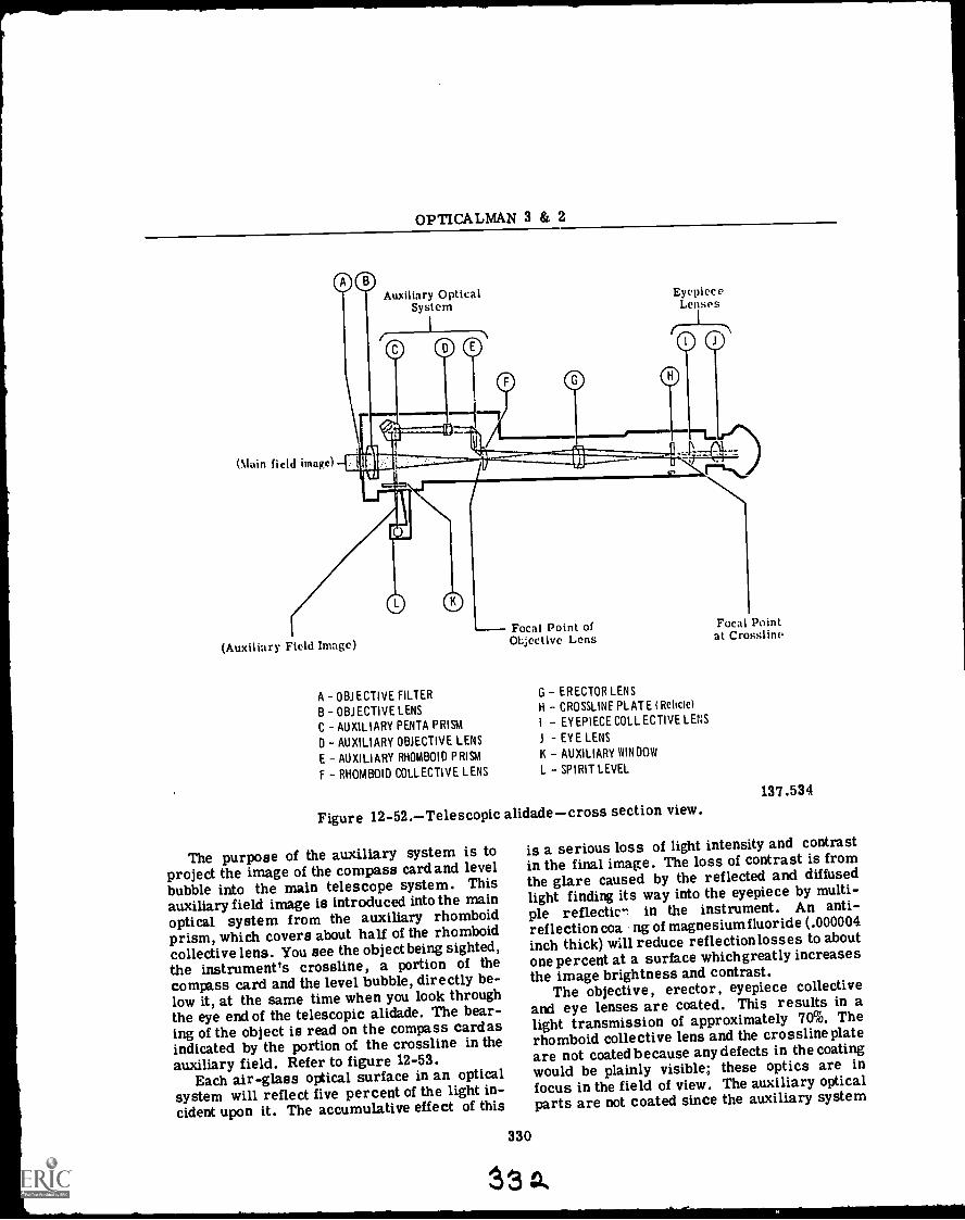
OPTICALMAN 3 & 2
(slain field image
Auxiliary OpticalSystem
EyepieceLenses
(Auxiliary Field Image)
A OBJECTIVE FILTER
B OBJECTIVE LENS
C AUXILIARY PENTA PRISM
0 AUXILIARY OBJECTIVE LENS
E AUXILIARY RHOMBOID PRISM
F RHOMBOID COLLECTIVE LENS
Focal Point ofOl;ective Lens
G - ERECTOR LENS
H CROSSLINE PLATE (Reticle)
I EYEPIECE COLLECTIVE LENS
1 EYE LENS
K - AUXILIARY WINDOW
L - SPIRIT LEVEL
Figure 12-52.Telescopic alidadecross section view.
The purpose of the auxiliary system is toproject the image of the compass card and levelbubble into the main telescope system. Thisauxiliary field image is introduced into the mainoptical system from the auxiliary rhomboidprism, which covers about half of the rhomboidcollective lens. You see the object being sighted,the instrument's crossline, a portion of thecompass card and the level bubble, directly be-low it, at the same time when you look throughthe eye end of the telescopic alidade. The bear-ing of the object is read on the compass card asindicated by the portion of the crossline in theauxiliary field. Refer to figure 12-53.
Each air-glass optical surface in an opticalsystem will reflect five percent of the light in-cident upon it. The accumulative effect of this
330
Focal Pointat Crogsline
137.534
is a serious loss of light intensity and contrastin the final image. The loss of contrast is fromthe glare caused by the reflected and diffusedlight finding its way into the eyepiece by multi-ple reflectien in the instrument. An anti -reflection coa ng of magnesium fluoride (.000004inch thick) will reduce reflection losses to aboutone percent at a surface whichgreatly increasesthe image brightness and contrast.
The objective, erector, eyepiece collectiveand eye lenses are coated. This results in alight transmission of approximately 70%. Therhomboid collective lens and the crossline plateare not coated because any defects in the coatingwould be plainly visible; these optics are infocus in the field of view. The auxiliary opticalparts are not coated since the auxiliary system
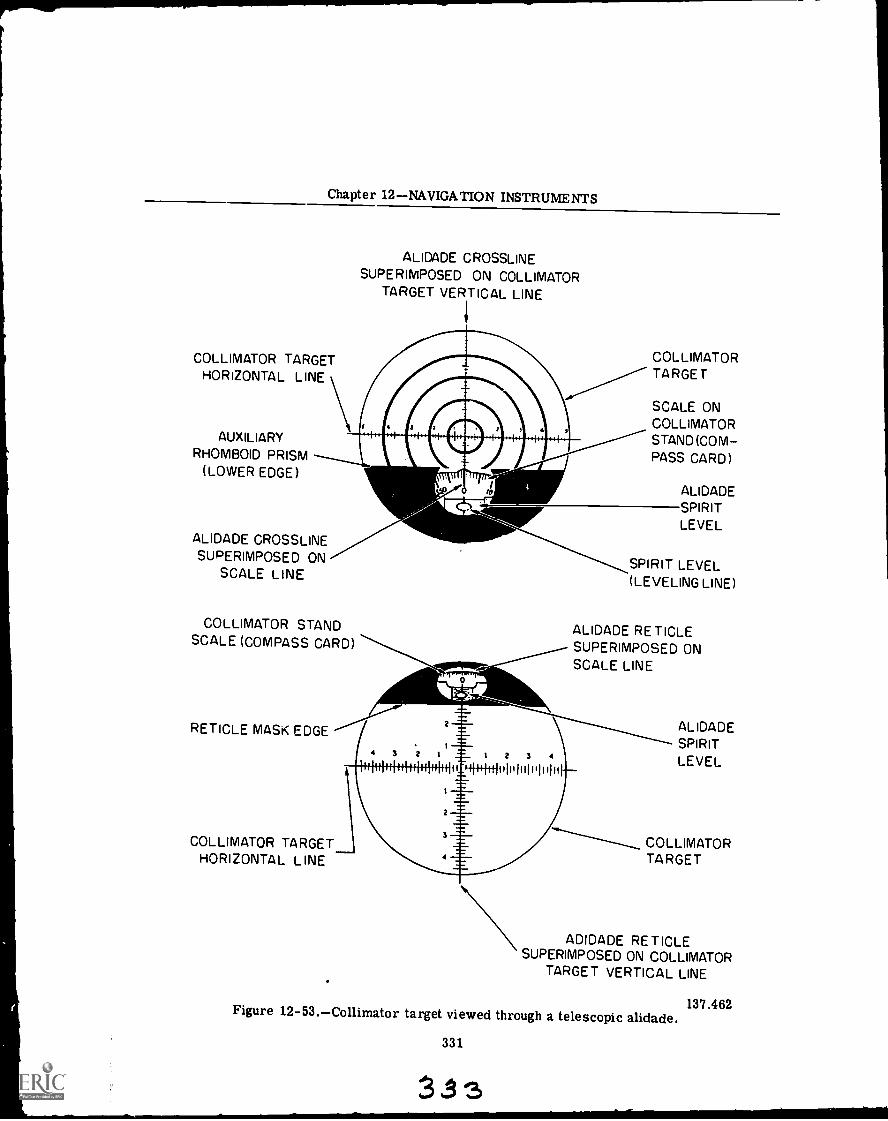
Chapter 12NAVIGATION INSTRUMENTS
COLLIMATOR TARGETHORIZONTAL LINE
AUXILIARYRHOMBOID PRISM
(LOWER EDGE)
ALIDADE CROSSLINESUPERIMPOSED ON COLLIMATOR
TARGET VERTICAL LINE
ALIDADE CROSSLINESUPERIMPOSED ON
SCALE LINE
COLLIMATOR STANDSCALE (COMPASS CARD)
RETICLE MASK EDGE
COLLIMATORTA RGE T
SCALE ONCOLLIMATORSTAND (COM-PASS CARD)
ALIDADESPIRITLEVEL
SPIRIT LEVEL(LEVELING LINE)
ALIDADE RETICLESUPERIMPOSED ONSCALE LINE
COLLIMATOR TARGETHORIZONTAL LINE
N
ALIDADESPIRITLEVEL
COLLIMATORTARGET
ADIDADE RETICLESUPERIMPOSED ON COLLIMATOR
TARGET VERTICAL LINE
137.462Figure 12-53.Collimator target viewed through a telescopic alidade.
331

OPTICALMAN 3 & 2
is required only to give an image of the compasscard which can be illuminated as bright as isnecessary by the compass illuminator lamp.
One of the principal design features of theMk 4 telescopic alidade is the attempt to makethe telescope waterproof and moistureproof byadding rubber gaskets to the seats of the eyelens and the objective lens, a rubber seal overthe objective mount and a scaling ring on theeyepiece. Where wax was used for sealing inearlier marks and mods, rubber gaskets areused in this alidade. The telescope body wasredesigned so that it is one piece instead ofthree, thereby eliminating joints where moisturecould enter the interior; the eyepiece mountmoves in and out of the end of the body insteadof having a separate adapter (as in the otheralidades). Instead of the conventional focusingring engaging a key on the eye lens mount, focus-ing is accomplished by turning a pinion, whichengages a rack cut on the eyepiece lens mount.Instead of being in a fixed plane, the crosslineplate is mounted in its own mount and is capableof being positioned in or out in relation to theeyepiece. The whole auxiliary telescope systemis mounted on a plate, permitting it to be madeup as a subassembly before being placed into thetelescope body. To absorb any moisture thatdoes get into the interior, a container of des-iccant (silica gel) is placed within the telescopebody. The body cover is made watertight by arubber gasket between it and the telescope body.
Mark 6 and Mark 7
The Mark 6 and Mark 7 alidades shown infigure 12 -51 are identical to each other in opticaldesign. They differ from each other only inmechanical features of the bearing ring assem-blies. The Mark 6 alidade attaches to a 6-inchmagnetic compass or ship's course indicatorand the Mark 7 alidade is equipped with anadaptor for mounting on the 7 1/2-inch NavyNumber 1 magnetic compass or the 7 1/2-inchship's course indicators.
The optical design of the Mk 6 and 7 alidade,as shown in figure 12-54, is similar to the basicdesign discussed previously. It has aterrestrialtelescope for viewing distant objects and anauxiliary optical system for simultaneous view-ing of the compass card and spirit level.
There are some differences in the individualoptical elements of the Mk 4 and Mk 6 and 7 ali-dade, so compare figures 12-52 and 12-54 as
you study the following description of the Mk 6and 7 alidade.
The main optical system of the Mark 6 and 7(fig. 12-54), telescopic alidade is a terrestrialtelescope which consists of an objective lens(piece 8), polarizing filters (2-piece 6), a com-pensator lens (piece 7), an Amici prism (piece 4),a reticle, and the eyepiece elements. The ob-jective lens receives light from a distant objectand forms an image which is subsequently mag-nified by the eyepiece optical elements. The twopolarizing filters may be rotated in or out of theline of sight as situations require. Placed inthe path of light, they reduce light intensity andglare. One polarizing fi !ter may be independentlyrotated to vary the intensity of light receivedfrom the distant object. The compensator lensis also mounted in the filter assembly, but it isonly positioned in the line of sight when thepolarizing filters have been rotated to the downposition. The compensator lens is used to con-verge the light path and maintain the requiredfocus when the polarizing filters are rotated outof the line of sight. The light from the com-pensator lens or polarizing filters is then focusedthrough a fixed stop aperture onto the eyepieceside of the Amici prism. The Amici prism in-verts and reverts the image and deviates theline of sight through a 45-degree angle. Therecticle wire is superimposed on the image andthe eyepiece elements, which consist of a fieldlens (piece 1), center lens (piece 2), and eyelens (piece 3) produce an enlarged virtual imageof the distant object at the eyepoint of the alidade.
The auxiliary optical system consists of asealing window (piece 9), front surface mirror(piece 13), an outer objective lens (piece 12), aninner objective lens (piece 11), erector lenses(2-piece 10), and an auxiliary optical systemprism (piece 5). The image of the compass orindicator card and level vial is transmittedthrough the window and reflected into the aux-iliary optical system by the front surf ace mirror.The inner and outer objective lenses convergethe image from the front surface mirror, througha stop in the erector lens cell, into the auxiliaryoptical system prism. The erector lens in-verts the image of the inner and outer objectivelens, while the auxiliary optical system prismre-inverts the image in the plane of the mask,and reticle wire. The reticle wire is super-imposed on the compass card and the bubble inthe level vial (piece 14), and an image isformedat the eyepoint of the alidade.
332
3 34
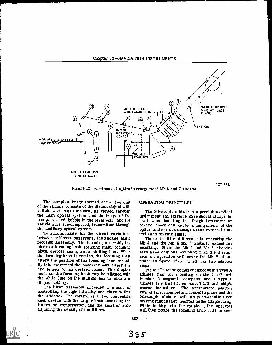
Chapter 12NAVIGATION INSTRUMENTS
MASK 8 RETICLEWIRE (IMAGE PLANE)
/ /
FILTERROTATIONAL riCENTER/ I i
I I
t
47L
IIROTATEDPOSITION
90°MAIN OPTICAL SYSTEMLINE OF SIGHT
AUX. OPT AL SYS.LINE SIGHT
L. MASK a RETICLEWIRE AT IMAGEPLANE
EYEPOINT
137.535Figure 12-54.General optical arrangement Mk 6 and 7 alidade.
The complete image formed at the eyepointof the alidade consists of the distant object withreticle wire superimposed, as viewed throughthe main optical system, and the image of thecompass card, bubble in the level vial, and thereticle wire superimposed, transmitted throughthe auxiliary optical system.
To accommodate for the visual variationsbetween different observers, the alidade has afocusing assembly. The focusing assembly in-cludes a focusing knob, focusing shaft, focusingplate, diopter scale, and a stuffing box. Whenthe focusing knob is rotated, the focusing shaftalters the position of the focusing lens mount.By this movement the observer may adjust theeye lenses to his desired focus. The diopterscale on the focusing knob may be aligned withthe white line on the stuffing box to obtain adiopter setting.
The filter assembly provides a means ofcontrolling the light intensity and glare withinthe alidade. The control is a two concentricknob device with the larger knob inserting thefilters or compensator, and the smaller knobadjusting the density of the filters.
333
OPERATING PRINCIPLES
The telescopic alidade is a precision opticalinstrument and extreme care should always beused when handling it. Rough treatment orsevere shock can cause misakrment of theoptics and serious damage to the external con-trols and bearing rings.
There is little difference in operating theMk 4 and the Mk 6 and 7 alidade, except formounting. Since the Mk 4 and Mk 6 alidadeseach have only one mounting ring, the discus-sion on operation will cover the Mk 7, illus-trated in figure 12-51, which has two adapterrings.
The Mk 7 alidade comes equipped w ith a Type Aadapter ring for mounting on the 7 1/2-inchNumber 1 magnetic compass, and a Type Badapter ring that fits on most 7 1/2-inch ship'scourse indicators. The appropriate adapterring is first mounted and locked in place and thetelescopic alidade, with its permanently fixedbearing ring is then mounted on the adapter ring.While looking into the eyepiece, the operatorwill then rotate the focusing knob r.ntil he sees
33g
OPTICALMAN 3 & 2
a clear image of the vertical reticle wire. Whenglare presents a problem, the operator shouldthen position the polarizing filters into theoptical system in a manner that allows for theclearest view.
After the alidade is mounted and adjusted forviewing, the operator should rotate the alidadeinto the general direction of the target. Whilesighting through the eyepiece, adjust the rota-tional position of the alidade until the targetimage is centered on the reticle wire. As soonas the reticle bisects the target, direct yourvision to the upper third of the eyepiece andread the bearing represented by the compasscard division indicated by the reticle wire.While reading the compass card division, checkthe position of the level bubble. The most ac-curate bearings are obtained when the alidadeis level.
REPAIR
Complete repair procedures and parts lists,for the Mk 4 telescope alidade, are given in theNAVSHIPS 250-624-5 technical manual. TheMk 6 and Mk 7 alidade are thoroughly coveredin NAVSHIPS 324-0488 and NAVSHIPS 0924-001-6000 te dmical manuals. The technical man-ualthat applies shouldalways be used as a guidewhen actually working on a telescopic alidade.
Here listed are some of the major points ofrepair that an opticalman should examine.
Inspect the alidade thoroughly to be certainall parts and assemblies are present.
Examine the housing for dents and cracks.Check the focusing and filter assemblies
for bent or broken parts. These assembliesshould operate easily.
Inspect for dirt and moisture on the in-terior optical parts; their presence will indicateimproper internal pressure in the housing.
The diopter scale must be clearly definedand easily readable.
The exterior finish of the alidade must beintact to maintain protection against corrosion.
No dirt, smears, scratches, digs, chips,fractures, fungus growth or cement separationsshould be visible inside the alidade as viewedthrough the objective lens. With the use of themethod called "shadowing," it is possible tolocate these defects in the lenses. Shadowingis the technique of looking obliquely into theeyepiece or objective end of an instrument toobtain a reflection from a particular surface inthe optical system. Seen in this way , the surfaces
of the lenses appear dark grey and any defectsshow up as white particles. If salt spray marksappear on the exterior glass surfaces, theyshould be removed by rinsing in freshwater be-fore any other glass cleaning is attempted.
Collimation
Collimation of a telescopic alidade is a step-by-step procedure of interdependent adjust-ments. The main optical system and also theauxiliary optical system must be collimated tothe mechanical axis of the bearing circle. Thefirst step is mechanical alignment of the bearingcircle with the axis of the collimator. The sec-ond step is alignment of the main optical systemwith the collimator. The third stepis alignmentof the auxiliary optical system with the mainoptical system.
The collimator generally used for collimat-ing a telescopic alidade is a Mk 4, Mod 0, in-strument, illustrated and discussed in chapter 8(fig. 8-4). The collimation procedure discussedin this section is for a Mk 6, or 1, telescopicalidade.
Bearing Axis: The alidade requires acollimator adapter which simulates the bezelring of the compass, and, in addition, containsa scale with graduations properly located andoriented to simulate the compass card. A settingfixture is also necessary to set the adapter sothat the center of the bezel ring and the centermark of the scale are capable of being alignedalong the line of sight of the collimator tele-scope.
Main Optical Prism Adjustment: The mainsystem Amici prism is bonded to a metal mountheld by three screws to the prism mount plate.Sufficient clearance is allowed for a small ad-justment in height, distance along axis, and ro-tation in a vertical plane defined by the opticalaxis, of the mounted prism. There is no pro-vision for rotation, or tilt, of the prism in anyother plane. After adjustment, screws must betaken up tightly.
AuxiliaryObjective Adjustment: In the ad-justment of the auxiliary system, it has beenfound advisable to set the erector assembly ap-proximately midway of its travel, and to adjustby moving the auxiliary objective cell in or out.This operation is best performed after the filterassembly has been removed, providing accessto the back end of the auxiliary objective cell.The set screw holding the auxiliary optical cellis below the forward nameplate screw, in the
334
33
Chapter 12NAVIGATION INSTRUMENTS
same threaded hole. Care should be taken toback off this set screw before attempting to re-move the cell, and to take it up tightly aftercompletion of the adjustment.
Auxiliary Mirror Adjustment: The aux-iliary optical system mirror, bonded to itsthreaded mount, can be adjusted to change theheight of the card and level vial images, tochange the lateral positioning of these images,and to tilt or correct tilt introduced by otherelements. All three of these adjustments arefunctions of the rotational and longitudinal posi-tion of the threaded mount in the housing castingwall, and, therefore they are not independent ad-justments. Care should be taken to make sureall three factors are satisfactory before lickingthe mount in position with its setscrew. Finaladjustment should not be made until the aux-iliary optical system prism has been adjustedand locked.
Auxiliary PrismAdjustment: The auxiliaryoptical system prism is bonded to a metal mountand fastened to the prism mount plate in a man-ner similar to that used with the main opticalsystem prism. Adjustments are the same. Anyrotation of image or sidewise displacement mustbe corrected by small rotational adjustments ofthe auxiliary mirror mount.
Fixed Polarizing Filter Adjustment: Re-moval or replacement. of the fixed polarizingfilter requires attention to its orientation in themount. Since it is required to reduce glare fromthe water surface, its index lines should be ver-tical, or perpendicular to the filter shaft, whenit is locked into position in the filter mount.This should be checked after tightening the re-taining ring, as the final movement of the re-tainer ring may have caused the filter to ro-tate.
335
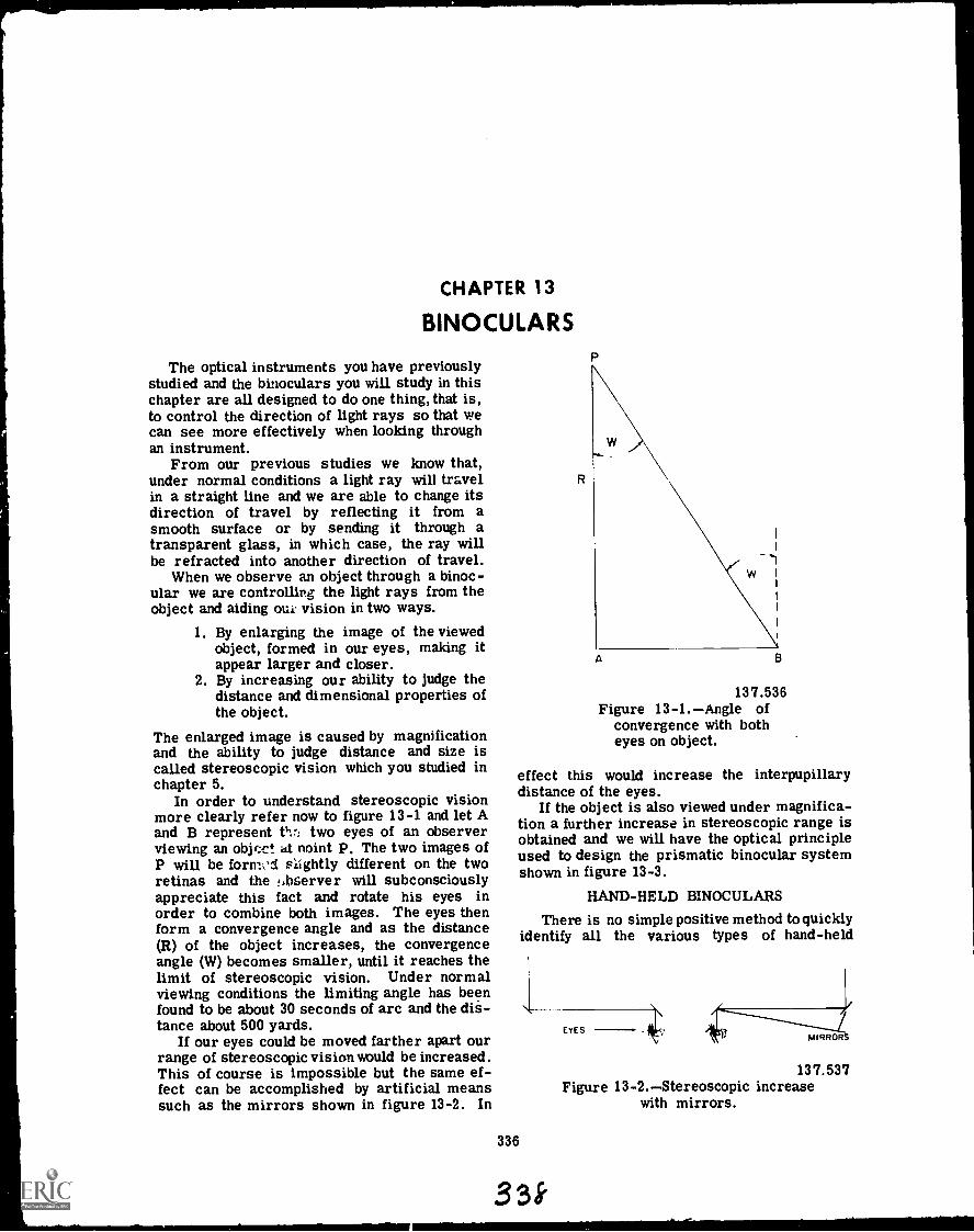
CHAPTER 13
BINOCULARS
The optical instruments you have previouslystudied and the binoculars you will study in thischapter are all designed to do one thing, that is,to control the direction of light rays so that wecan see more effectively when looking throughan instrument.
From our previous studies we know that,under normal conditions a light ray will travelin a straight line and we are able to change itsdirection of travel by reflecting it from asmooth surface or by sending it through atransparent glass, in which case, the ray willbe refracted into another direction of travel.
When we observe an object through a binoc-ular we are controlling the light rays from theobject and aiding oue vision in two ways.
1. By enlarging the image of the viewedobject, formed in our eyes, making itappear larger and closer.
2. By increasing our ability to judge thedistance and dimensional properties ofthe object.
The enlarged image is caused by magnificationand the ability to judge distance and size iscalled stereoscopic vision which you studied inchapter 5.
In order to understand stereoscopic visionmore clearly refer now to figure 13-1 and let Aand B represent nr: two eyes of an observerviewing an object at noint P. The two images ofP will be form,sd slightly different on the tworetinas and the !,bserver will subconsciouslyappreciate this fact and rotate his eyes inorder to combine both images. The eyes thenform a convergence angle and as the distance(R) of the object increases, the convergenceangle (W) becomes smaller, until it reaches thelimit of stereoscopic vision. Under normalviewing conditions the limiting angle has beenfound to be about 30 seconds of arc and the dis-tance about 500 yards.
If our eyes could be moved farther apart ourrange of stereoscopic vision would be increased.This of course is impossible but the same ef-fect can be accomplished by artificial meanssuch as the mirrors shown in figure 13-2. In
R
A
137.536Figure 13-1.Angle of
convergence with botheyes on object.
effect this would increase the interpupillarydistance of the eyes.
If the object is also viewed under magnifica-tion a further increase in stereoscopic range isobtained and we will have the optical principleused to design the prismatic binocular systemshown in figure 13-3.
HAND-HELD BINOCULARS
There is no simple positive method to quicklyidentify all the various types of hand-held
336
33k
EYES
137.537Figure 13-2.Stereoscopic increase
with mirrors.
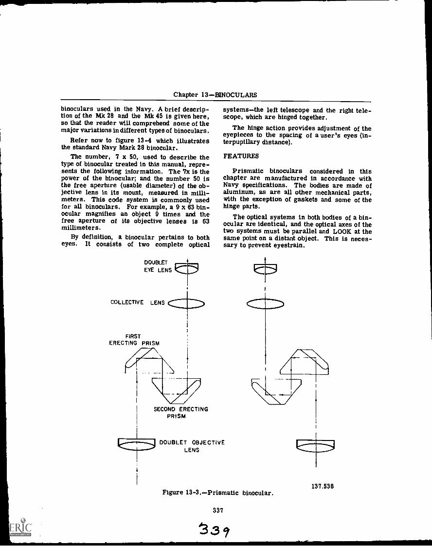
Chapter 13BINOCULARS
binoculars used in the Navy. A brief descrip-tion of the Mk 28 and the Mk 45 is given here,so that the reader will comprehend some of themajor variations in different types of binoculars.
Refer now to figure 13-4 which illustratesthe standard Navy Mark 28 binocular.
The number, 7 x 50, used to describe thetype of binocular treated in this manual, repre-sents the following information. The 7x is thepower of the binocular; and the number 50 isthe free aperture (usable diameter) of the ob-jective lens in its mount, measured in milli-meters. This code system is commonly usedfor all binoculars. For example, a 9 x 63 bin-ocular magnifies an object 9 times and thefree aperture of its objective lenses is 63millimeters.
By definition, a binocular pertains to botheyes. It consists of two complete optical
DOUBLET
EYE LENS
COLLECTIVE LENS
FIRSTERECTING PRISM
I
SECOND ERECTINGPRISM
systemsthe left telescope and the right tele-scope, which are hinged together.
The hinge action provides adjustment of theeyepieces to the spacing of a user's eyes (in-terpupillary distance).
FEATURES
Prismatic binoculars considered in thischapter are manufactured in accordance withNavy specifications. The bodies are made ofaluminum, as are all other mechanical parts,with the exception of gaskets and some of thehinge parts.
The optical systems in both bodies of a bin-ocular are identical, and the optical axes of thetwo systems must be parallel and LOOK at thesame point on a distant object. This is neces-sary to prevent eyestrain.
DOUBLET OBJECTIVELENS
Figure 13-3.Prismatic binocular.
337
33 ?
137.538
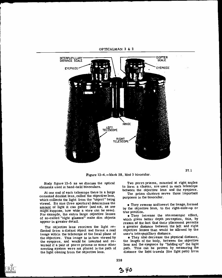
OPTICALMAN 3 & 2
INTERPUPILLARYDISTANCE SCALE
EYEPIECE L
111' 1-11
LEFTTELESCOPE
VHINGE
RIGHT r'irTELESCOPE
DIOPTERSCALE
EYEPIECE
Figure 13-4.Mark 28, Mod 0 binocular.
Study figure 13-5 as we discuss the opticalelements used in hand-held binoculars.
At one end of each telescope there is a largecemented doublet lens, called the objective lens,which collects the light from the "object" beingviewed. Its size (free aperture) determines theamount of light it can gather (and not, as onemight suppose, how wide a view can be seen).For example, the extra large objective lensesof so-called "night glasses" make dim objectsappear in greater detail.
The objective lens receives the light re-flected from a distant object and forms a realimage within the telescope at the focal plane ofthe objective. This image is in turn viewed bythe eyepiece, and would be inverted and re-versed if a pair of porro prisms or some othererecting system were not placed in the path ofthe light coming from the objective lens.
338
Of
37.1
Two porro prisms, mounted at right anglesto form a cluster, are used in each telescopebetween the objective lens and the eyepiece.
The prism clusters serve three importantpurposes in the binocular.
They reverse and invert the image, formedby the objective lens, to the right-side-up ortrue position.
They increase the stereoscopic effect,which gives better depth perception, this, byreason of the fact that their placement permitsa greater distance between the left and rightobjective lenses than would be allowed by theuser's interpupillary distance.
They also decrease the physical distance,the length of the body, between the objectivelens and the eyepiece by "folding up" the lightpath. This can be proven by measuring thedistance the light travels (the light path) from
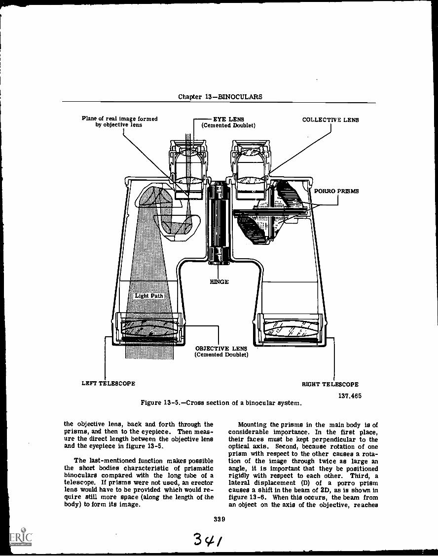
Chapter 13BINOCULARS
Plane of real image formed EYE LENSby objective lens (Cemented Doublet)
COLLECTIVE LENS
PORRO PRISMS
HINGE
LEFT TELESCOPE
OBJECTIVE LENS(Cemented Doublet)
Figure 13-5.Cross section of a binocular system.
the objective lens, back and forth through theprisms, and then to the eyepiece. Then meas-ure the direct length between the objective lensand the eyepiece in figure 13-5.
The last-mentioned function makes possiblethe short bodies characteristic of prismaticbinoculars compared with the long tube of atelescope. If prisms were not used, an erectorlens would have to be provided which would re-quire still more space (along the length of thebody) to form its image.
339
3'
RIGHT TELESCOPE
137.465
Mounting the prisms in the main body is ofconsiderable importance. In the first place,their faces must be kept perpendicular to theoptical axis. Second, because rotation of oneprism with respect to the other causes a rota-tion of the image through twice as large anangle, it is important that they be positionedrigidly with respect to each other. Third, alateral displacement (D) of a porro prismcauses a shift in the beam of 2D, as is shown infigure 13-6. When this occurs, the beam froman object on the axis of the objective, reaches
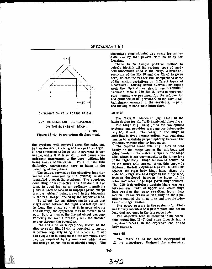
OPTICALMAN 3 & 2
Adi\\_..N,
A
2D 1D. SLIGHT SHIFT IN PORRO PRISM.
2D. THE RESULTANT DISPLACEMENT
ON THE EMERGENT BEAM.
137.539Figure 13-6.Porro prism displacement.
the eyepiece well removed from the axis, andis thus deviated, arriving at the eye at an angle.If this deviation is large the instrument is un-usable, while if it is small it will cause con-siderable discomfort to the user, without hisbeing aware of the cause. To eliminate thisdifficulty, considerable care is taken in themounting of the prisms.
The image, formed by the objective lens (in-verted and reversed by the prisms) is seenmagnified through the eyepiece. The eyepiece,consisting of a collective lens and doublet eyelens, is used just as an ordinary magnifyingglass is used to look at newspaper print exceptthat the "object" being viewed in the binocularis the real image formed by the objective lens.
To adjust for any difference in vision thatmight exist between the right and left eye, andto focus the image so that it is seen sharplyand clearly, the eyepieces may be moved in orout. By this means, the distant object can con-veniently be seen alternately with the unaidedeye or through the binocular.
The scale on each eyepiece, known as thediopter scale (fig. 13-4), is provided to permita person regularly using the binocular to setthe eyepieces to compensate for any visualcor-rection required by his own eyes which doesnot change unless his eyes should change. The
binoculars once adjusted are ready for imme-diate use by that person with no delay forfocusing.
There is no simple positive method toquickly identify all the various types of hand-held binoculars used in the Navy. A brief de-scription of the Mk 28 and the Mk 45 is givenhere, so that the reader will comprehend someof the major variations in different types ofbinoculars. During actual overhaul or repairwork the Opticalman should use NAVSHIPSTechnical Manual 250-624-2. This comprehen-sive manual was prepared for the informationand guidance of all personnel in the Naval Es-tablishment engaged in the servicing, repair,and testing of hand-held binoculars.
Mark 28
The Mark 28 binocular (fig. 13-4) is thebasic design for all 7 x 50 hand-held binoculars.
The hinge (fig. 13-7) joins the two opticalsystems and provides a means for interpupil-lary adjustment. The design of the hinge issuch that it gives smooth action, with sufficienttension to maintain proper spacing between thesystems, without play or looseness.
The tapered hinge axle (fig. 13-7) is heldfirmly in the hinge lugs of the left body andrides freely in the matching taper of the hingetube, which is set permanently in the hinge lugsof the right body. Hinge tension is controlledby the lower axle screw. When this screw istightened, the left body hinge lugs are SQUEEZEDagainst the right body hinge lugs. Since theright body lugs are held rigid by the hinge tube,friction developed between the faces of theouter and inner hinge lugs gives hinge tension.The .010-inch cellulose acetate hinge washersbetween each pair of upper and lower hingelugs receive the wear resulting from hingemotion. These washers fit firmly in their po-sitions against the hinge lugs and provide fric-tion for hinge tension.
The porro prisms in the system (fig. 13-8)are firmly mounted on a prism plate and set onlugs that are cast in the telescope body.
The objective lens is mounted in an eccen-tric mount (fig. 13-9) that slips directly into amachined recess in the objective end of thebody casting.
340
Mark 45
The Mark 45 is the most waterproof ofall the binoculars. Designed for underwater
4/2
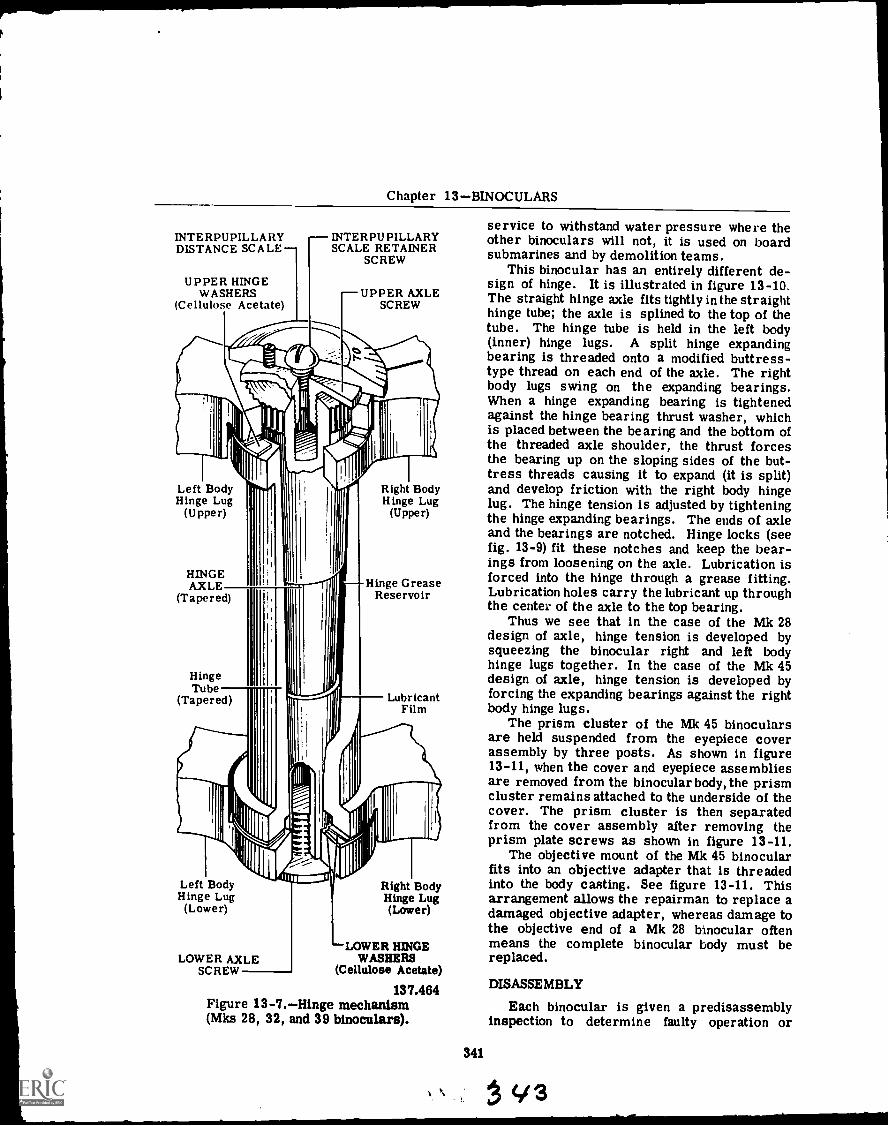
Chapter 13BINOCULARS
INTERPUPILLARYDISTANCE SCALE
UPPER HINGEWASHERS
(Cellulose Acetate)
INTERPUPILLARYSCALE RETAINER
SCREW
UPPER AXLESCREW
Left BodyHinge Lug
(Upper)
HINGEAXLE
(Tapered)
HingeTube
(Tapered)
Right BodyHinge Lug
(Upper)
Hinge GreaseReservoir
LubricantFilm
Left BodyHinge Lug
(Lower)
LOWER AXLESCREW
Right BodyHinge Lug(Lower)
LOWER HINGEWASHERS
(Cellulose Acetate)
137.464Figure 13-7.Hinge mechanism(Mks 28, 32, and 39 binoculars).
service to withstand water pressure where theother binoculars will not, it is used on boardsubmarines and by demolition teams.
This binocular has an entirely different de-sign of hinge. It is illustrated in figure 13-10.The straight hinge axle fits tightly in the straighthinge tube; the axle is splined to the top of thetube. The hinge tube is held in the left body(inner) hinge lugs. A split hinge expandingbearing is threaded onto a modified buttress-type thread on each end of the axle. The rightbody lugs swing on the expanding bearings.When a hinge expanding bearing is tightenedagainst the hinge bearing thrust washer, whichis placed between the bearing and the bottom ofthe threaded axle shoulder, the thrust forcesthe bearing up on the sloping sides of the but-tress threads causing it to expand (it is split)and develop friction with the right body hingelug. The hinge tension is adjusted by tighteningthe hinge expanding bearings. The ends of axleand the bearings are notched. Hinge locks (seefig. 13-9) fit these notches and keep the bear-ings from loosening on the axle. Lubrication isforced into the hinge through a grease fitting.Lubrication holes carry the lubricant up throughthe center of the axle to the top bearing.
Thus we see that in the case of the Mk 28design of axle, hinge tension is developed bysqueezing the binocular right and left bodyhinge lugs together. In the case of the Mk 45design of axle, hinge tension is developed byforcing the expanding bearings against the rightbody hinge lugs.
The prism cluster of the Mk 45 binocularsare held suspended from the eyepiece coverassembly by three posts. As shown in figure13-11, when the cover and eyepiece assembliesare removed from the binocular body, the prismcluster remains attached to the underside of thecover. The prism cluster is then separatedfrom the cover assembly after removing theprism plate screws as shown in figure 13-11.
The objective mount of the Mk 45 binocularfits into an objective adapter that is threadedinto the body casting. See figure 13-11. Thisarrangement allows the repairman to replace adamaged objective adapter, whereas damage tothe objective end of a Mk 28 binocular oftenmeans the complete binocular body must bereplaced.
341
DISASSEMBLY
Each binocular is given a predisassemblyinspection to determine faulty operation or
3
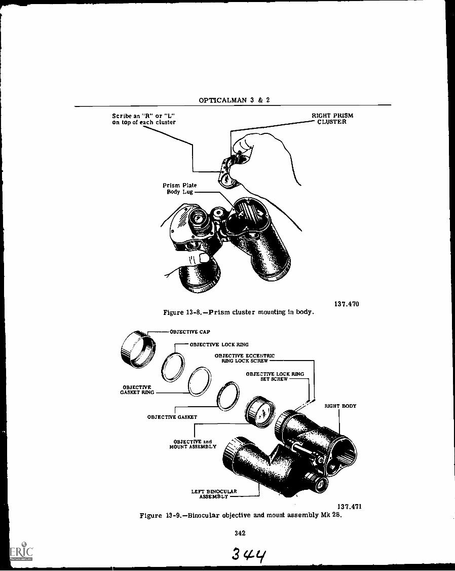
OPTICALMAN 3 & 2
Scribe an "R" or "L"on top of each cluster CLUSTER
RIGHT PRISM
Prism PlateBody Lug
. .,
Figure 13-8.Prism cluster mounting in body.
OBJECTIVE CAP
OBJECTIVE LOCK RING
OBJECTIVE ECCENTRICRING LOCK SCREW
OBJECTIVE LOCK RINGSET SCREW
OBJECTIVEGASKET RING
137.470
RIGHT BODY
OBJECTIVE GASKET
OBJECTIVE andMOUNT ASSEMBLY
LEFT BINOCULARASSEMBLY
137.471Figure 13-9.Binocular objective and mount assembly Mk 28.
342
344ty
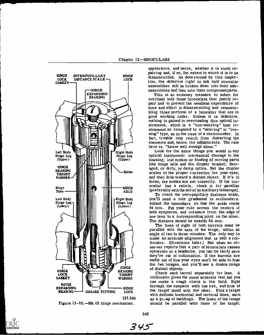
Chapter 13BINOCULARS
HINGE INTERPUPILLARYLOCK DISTANCE SCALE
GASKETHINGELOCK
HINGEEXPANDING
BEARING
Left BodyHinge Lug(Upper)
HINGEBEARINGTHRUST]WASHER
Right BodyHinge Lug
(Upper)
HingeTube
Left BodyHinge Lug(Lower)
Spline
HINGEAXLE
Right BodyHinge Lug
(Lower)
HINGELOCK
GASKET
HA GEEXPANDING
BEARING GREASE FITTING
HINGEBEARINGTHRUSTWASHER
HINGELOCK
137.540Figure 13-10.Mk 45 hinge mechanism.
appearance, and hence, whether it is worth re-pairing and, if so, the extent to which it is to bedisassembled. As determined by this inspec-tion, the defective right or left half binocularassemblies will be broken down into their sub-assemblies and then into their componentparts.
This is an economy measure to select foroverhaul only those binoculars that justify re-pair and to prevent the needless expenditure oftime and effort in disassembling and reassem-bling those portions of a binocular that are ingood working order. Unless it is defective,nothing is gained in overhauling this optical in-strument, which is a "non-wearing" type in-strument as compared to a "wearing" or "run-ning" type, as in the case of a chronometer. Infact, trouble may result from disturbing theelements and, hence, the adjustments. The rulehere is, "Leave well enough alone."
Look for the same things you would in anyoptical instrument: mechanical damage to thehousing; lost motion or binding of moving parts(the hinge axle and the diopter scales); dam-aged, or dirty, or damp optics. Set the diopterscales to the proper correction for your eyes,and then look toward a distant object. If it's infocus, the scales are set correctly. If the bin-ocular has a reticle, check it for parallax(preferably with the aid of an auxiliary telescope).
To check the interpupillary distance scale,you'll need a rule graduated in millimeters.Adjust the binoculars so that the scale reads64 mm. Put your rule across the centers ofboth eyepieces, and measure from the edge ofone lens to a corresponding point on the other.The distance should be exactly 64 mm.
The lines of sight of both barrels must beparallel with the axis of the hinge, within anangle of two to three minutes. The only way tomake an accurate alignment test is with a col-limator. (Directions later.) But when an ob-server reports that a pair of binoculars causeseyestrain or a headache, you can be fairly surethey're out of collimation. If the barrels arebadly out of line your eyes won't be able to fusethe two images, and you'll see a double imageof distant objects.
Check each barrel separately for lean. Acollimator gives the most accurate test, but youcan make a rough check in the field. Sightthrough the eyepiece with one eye, and look atthe target itself with the other. Pick a targetwith definite horizontal and vertical lines, suchas a gr,,up of buildings. The lines of the imageshould be parallel with those of the target.
343
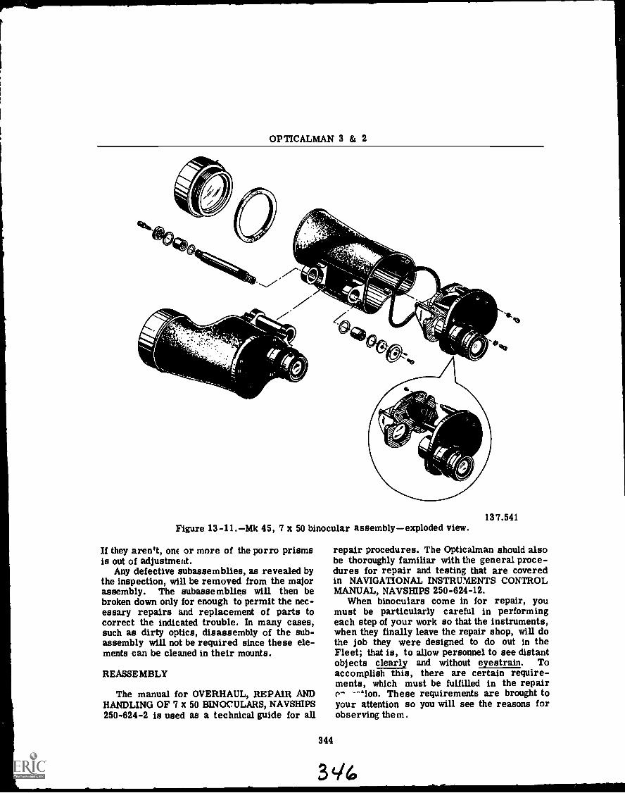
OPTICALMAN 3 & 2
137.541Figure 13-11.Mk 45, 7 x 50 binocular assemblyexploded view.
If they aren't, one or more of the porro prismsis out of adjustment.
Any defective subassemblies, as revealed bythe inspection, will be removed from the majorassembly. The subassemblies will then bebroken down only for enough to permit the nec-essary repairs emd replacement of parts tocorrect the indicated trouble. In many cases,such as dirty optics, disassembly of the sub-assembly will not be required since these ele-ments can be cleaned in their mounts.
REASSEMBLY
The manual for OVERHAUL, REPAIR ANDHANDLING OF 7 x 50 BINOCULARS, NAVSHIPS250-624-2 is used as a technical guide for all
repair procedures. The Opticalman should alsobe thoroughly familiar with the general proce-dures for repair and testing that are coveredin NAVIGATIONAL INSTRUMENTS CONTROLMANUAL, NAVSHIPS 250-624-12.
When binoculars come in for repair, youmust be particularly careful in performingeach step of your work so that the instruments,when they finally leave the repair shop, will dothe job they were designed to do out in theFleet; that is, to allow personnel to see distantobjects clearly and without eyestrain. Toaccomplish this, there are certain require-ments, which must be fulfilled in the repaire~ -"ion. These requirements are brought toyour attention so you will see the reasons forobserving them.
344
34./4

Chapter 13BINOCULARS
The repairman is charged with the respon-sibility of preparing a complete set of service-able parts for efficient reassembly. Followingan inspection to determine defects, the partsare repaired or replaced in accordance withthe "Parts Inspection Standards" as referencedin the Control Manual index.
Replacement parts are to be obtained fromstock. The Federal Stock Catalog is used as asource for stock numbers and also to indicatesubassemblies or matched parts which must bereplaced as units. All mechanical parts arecleaned. Matched optical parts are checked onspecial testing fixtures to facilitate compliancewith the optical requirements. The completeset of inspected and approved parts of the bin-ocular is then returned to the individual partstray.
Considerable work will be saved if the bin-ocular parts are reassembled to the same in-strument from which they were disassembled,and in the same system (right or left) out ofwhich they came.
There are matched and fitted parts thatmust remain together. The manufacturers"sweated it out" for you, so don't make unnec-essary work for yourself and others by mixingup these parts.
The matching of each objective lens to itsindividual mount is necessary to make surethat the images formed by the two objectivelenses focus at the same distance along thelength of the body. If this is not done, the eye-pieces will project unevenly from the body sincethey must focus on the images formed by eachof the objective lenses. With uneven eyepieces,the user could not look straight into both eye-pieces with his eyes against the eyepiececaps which is a necessary condition for bestperformance.
The prisms of each prism cluster must bematched to each other to eliminate the inherenterror in individual prisms to deviate a beam oflight, being reflected by it, from a normal opti-cal axis. The size of the prisms also influencesthe position of the image formed by the objec-tive lens, causing the same difficulty as statedfor the condition of unmatched objective lensesand mounts. The prisms are matched in pairsto provide clusters that have allowable errorsof deviation and path length.
Even if the lenses and prisms are perfect,in order to obtain the highest degree of clarityin vision, cleanliness of the optical surfacesis of the utmost importance in a binocular.
Polished surfaces must be free from any objec-tionable scratches, stains and other defectsvisible in the field of vision, or opticalperform-ance will be impaired. A tiny speck of dust orlint, if in or near the plane of the real image,can obscure a far-away point that an observermay be trying to distinguish. There must be nodirt, dust or any foreign particles in the inte-rior of the binocular which in time might gatheron the optics and weaken or block the image ofa viewed object. Particles of dirt, dust orgrease make the binoculars more susceptibleto fogging by condensation of vapor.
To maintain the cleanliness and functionalefficiency of optics, they have to be handledproperly. "Handling Glass Optics" in the Con-trol Manual includes details on this subject;however, a few words of caution should be men-tioned here. Recent scientific studies haveshown that a fingerprint on an optic is moreobjectionable than even a scratch! Finger-prints not only leave a film on an optical sur-face that cuts down light transmission but thefilm has a tendency to etch and permanentlyinjure the optical quality. Do not touch thepolished surfaces of optics; clean off accidentalfingerprints immediately.
Rough or careless handling will scratch theoptical surfaces. Scratches will diffuse lightand reduce the clarity of the image.
When optical surfaces are coated with ananti-reflection coating, scratches and abrasionswill rub it off and defeat its purpose. Thecoating is only four millionths of an inch inthickness and it is softer than glass; therefore,great care is necessary to avoid damage.
At disassembly, all optical parts should bewrapped in lens tissue to protect them fromaccidental damage.
Throughout the phases of the overhaul pro-cedure, the binoculars will be handled as as-semblies, subassemblies and parts. Precau-tions must be taken at all times to preventdamage.
An example of this is the treatment of thebinocular assembly after reassembly has beencompleted. The binoculars will most likely bestood on their objective end while awaiting testand adjustment. If they are set down hard,there is the danger of bending the relativelythin wall of the objective end of the body whichwill damage the internal thread for the objec-tive lock ring. Damage at this point wouldprobably require some disassembly and re-assembly which would be costly and wasteful.
345
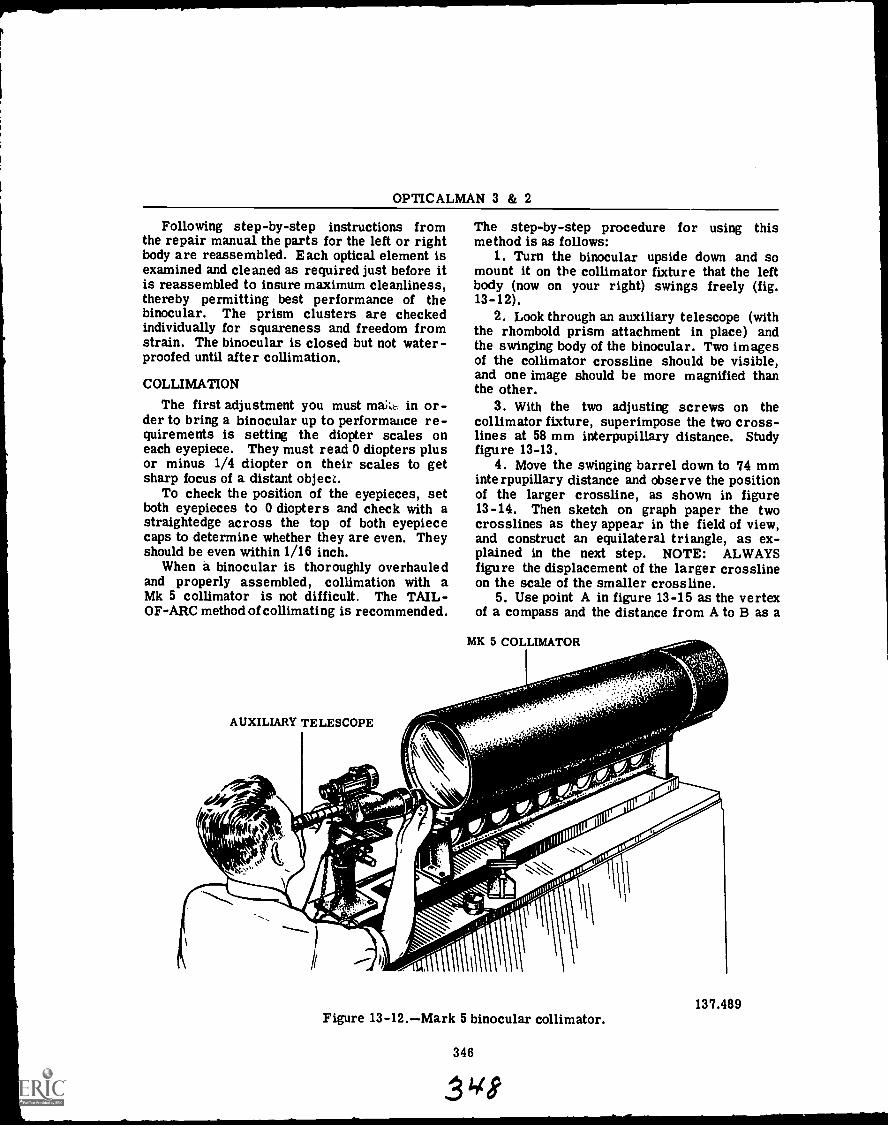
OPTICALMAN 3 & 2
Following step-by-step instructions fromthe repair manual the parts for the left or rightbody are reassembled. Each optical element isexamined and cleaned as required just before itis reassembled to insure maximum cleanliness,thereby permitting best performance of thebinocular. The prism clusters are checkedindividually for squareness and freedom fromstrain. The binocular is closed but not water-proofed until after collimation.
COLLIMATION
The first adjustment you must make in or-der to bring a binocular up to performance re-quirements is setting the diopter scales oneach eyepiece. They must read 0 diopters plusor minus 1/4 diopter on their scales to getsharp focus of a distant object.
To check the position of the eyepieces, setboth eyepieces to 0 diopters and check with astraightedge across the top of both eyepiececaps to determine whether they are even. Theyshould be even within 1/16 inch.
When a binocular is thoroughly overhauledand properly assembled, collimation with aMk 5 collimator is not difficult. The TAIL-OF-ARC method of collimating is recommended.
AUXILIARY TELESCOPE
The step-by-step procedure for using thismethod is as follows:
1. Turn the binocular upside down and somount it on the collimator fixture that the leftbody (now on your right) swings freely (fig.13-12).
2. Look through an auxiliary telescope (withthe rhomboid prism attachment in place) andthe swinging body of the binocular. Two imagesof the collimator crossline should be visible,and one image should be more magnified thanthe other.
3. With the two adjusting screws on thecollimator fixture, superimpose the two cross-lines at 58 mm interpupillary distance. Studyfigure 13-13.
4. Move the swinging barrel down to 74 mminterpupillary distance and observe the positionof the larger crossline, as shown in figure13-14. Then sketch on graph paper the twocrosslines as they appear in the field of view,and construct an equilateral triangle, as ex-plained in the next step. NOTE: ALWAYSfigure the displacement of the larger crosslineon the scale of the smaller crossline.
5. Use point A in figure 13-15 as the vertexof a compass and the distance from A to B as a
MK 5 COLLIMATOR
'7's'"'
137.489Figure 13-12.Mark 5 binocular collimator.
346
3418

Chapter 13BINOCULARS
A B
11111 11111 II
MPI
swim.
137.490Figure 13-13.Binocular crosslines
superimposed at 58 mm interpupil-lary distance.
4-
137.491Figure 13-14.Position of binocular
crosslines (A & B) when the inter-pupillary distance is at 74 mm.
radius and draw an arc CLOCKWISE from B.NOTE: Point A is the intersection point of the
Ar-7
4 ii-liwilfh.-+t;{ HEill-f-111i+
111 1111I
347
=B ,
illirillilf11111111111111
137.492Figure 13-15.Locating the mechanical
axis of a binocular.
smaller crossline and B is the point of inter-section of the larger crossline. Next, use pointB as the vertex of your compass (with the sameradius) and draw another arc which crosses thefirst arc. This is represented by C in figure13-15, and C is the mechanical axis of the bin-ocular. The distance from one letter to theother is the same, and the triangle formed byconnecting points A, B, and C, is thereforeequilateral.
NOTE: ALWAYS draw the FIRST arc clock-wise from point B.
6. Observe the vertical and horizontal dis-placement of point C.
7. Look through the auxiliary telescope andthe swinging body of the binocular and mentallytransfer the triangle to your field of view.Then manipulate the objective ( ccIntric ringsuntil the point of intersection of the largercrossline is at point C.
8. Repeat steps 4 through 7 uritil the cross-lines remain superimposed at all settings whenthe swinging barrel is moved from 58 mm to74 mm interpupillary distance.
9. Exercise care to prevent throwing theobjective mount out of collimation and lock theobjective mount setscrew and the objective lockring.
10. Leave the mechanical adjustments to thecollimator fixture intact and look through the

OPTICALMAN 3 & 2
stationary body with the auxiliary telescope.Then manipulate the objective eccentric ringsuntil the crosslines are superimposed.
11. With the objective ring setscrew, lock theobjective eccentric rings in place. CAUTION:Do NOT throw the barrel out of collimation.
12. Replace the objective gaskets, the objec-tive gasket rings, and the objective lock rings.
13. Check both bodies again to make certainthe instrument was not thrown out of collima-tion. Then replace the objective lock ringsetscrews.
14. Put a drop of sealing compound over theobjective ring and the objective lock ring set-screws. Then replace the objective caps.
15. Give the instrument another check to besure it is still collimated.
Binoculars must meet specific tolerancesand performance requirements before they arereturned to service, as follows:
The optical axis of the two telescopesmust be parallel within: (a) 2 minutes' step(vertical alignment of the two axes); (b) 4 min-utes' divergence (spreading apart of the twoaxes); and (c) 2 minutes' convergence (comingtogether of the two axes). CAUTION: Failureof the axis to stay within these tolerancescauses eyestrain, sometimes severe and ac-companied by nausea.
When both eyepieces are set to the samediopter reading, they should be even within 1/16inch. Deviation from this tolerance causeseyestrain.
The images of a distant, vertical, straightline formed in the two telescopes must beparallel to each other within 1 degree. This isa very liberal tolerance. Failure of the imagesto stay within this tolerance results in eyestrain.
Hinge tension of a binocular is most im-portant. At 70°F, plus or minus 5°, the unsup-ported side must support a load of 1.80 to 3pounds at a distance of five inches from thecenter of the hinge (9 inch pounds minimum and15 inch pounds maximum). Part of the weightis to the unsupported side of the binocular. Ifthe hinge is TOO tight, it will NOT permit ad-justment over the interpupillary distance range.If the hinge is TOO loose, it will not maintainany interpupillary setting.
Interpupillary scale readings must beaccurate within 1 millimeter. Deviation fromthis tolerance causes eyestrain.
The diopter scales must be set to givereadings accurate within 1/4 diopter. If this
tolerance is not maintained, a blurred imageand eyestrain result.
Loss of image fidelity results when opti-cal elements in a binocular are improperlymounted. The image is distorted. Tests of twocharacteristics of optical performance (centralastigmatism and central resolution) provide anoverall check on both design and service de-fects. NOTE: Most defects are eliminated bydesign of the instrument.
Objects in the center of the FIELD OF VIEWthat subtend an angle of 4 seconds of arc mustbe clearly resolved. In terms of the test to bemade, equal-width lines equally spaced .018inches on centers must be clearly visible asseparate and distinct when viewed at 77 feet.Failure to stay within this tolerance results inBLURRED and/or DISTORTED images andeyestrain.
Each telescope of a binocular must trans-mit at least 75 percent of the white light beingviewed, and the transmission of the two barrelsmay not differ by more than 3 percent. Givethe binocular a functional test and inspect theoptics for proper coating. Loss of light, imagebrightness, and glare, result when this toler-ance is not maintained.
When submerged in water, a binocularmust withstand a pressure of 3 pounds persquare inch; otherwise, moisture will collect inthe instrument during service. This means thatsealing of the instrument must be thorough.
To test a binocular's resistance to shock,drop it from a height of six feet into a box con-taining six inches of sand and then recheckalignment on the collimator. If the binocularcannot withstand this test, it will be knockedout of collimation during normal usage.
348
SHIP-MOUNTED BINOCULAR
The ship-mounted binocular is used by thequartermaster or signalman in conjunction withvisual signaling operations on many ships. TheNavy uses both the Mark 3 Mod 1 and the Mark 3Mod 2 ship-mounted binocular. Except as notedherein, the only difference in the two Modsis that the Mod 1 binocular is secured to aC-shaped bracket on the elevating carriage bya means of a dove-tailed plate, whereas theMod 2 binocular housing is fitted with trunnionswhich are secured to a U-shaped yoke on theelevating carriage. The procedures for dis-assembly and reassembly are the same forboth the Mod 1 and Mod 2.

Chapter 13-- BINOCULARS
1. BINOCULAR ASSEMBLY
2. CARRIAGE ASSEMBLY
3. BULKHEAD BRACKET
4. PEDESTAL ASSEMBLY
5. SWIVELLING F.YEBOLTS
69.18Figure 13-16.Ship bin( zular.
In the next few pages we will discuss theMark 3 Mod 2 (fig. 13-16). Information is pro-vided on the means of mounting the binocularassembly and the construction of the binocularassembly itself. Step-by-step procedures aregiven for the disassembly, reassembly, andcharging of the binocular.
34'd
3n
CHAR ACT;:i..AISTICS
Tie design characteristic:3 oMod Llinocular are:
MagnificationClear aperture of objectiveTrue field of view
f the Mark 3
20 power120 mm3° 30'
OPTICALMAN 3 & 2
Eye distance (at zerodiopters) 22 5 mm
. 70°6 mm
. . 56-74 mm
Apparent field (approx.)Exit pupilInterpupillary distanceMaximum elevation of
line of sightMaximum depression of
line of sightOverall binocular length
(sunshade extended) . . .
Overall binocular width . .Height above bulkhead
bracket or pedestal:Extended (eyepiece
LOS)Retracted (eyepiece
LOS)
60°
-10°
20.375 inches. 22.5 inches
35 375 inches
27 375 inches
The binocular assembly contains the opticsrequired to obtain the desired magnificationand provision is made to install an illuminatedreticle if required. An illuminated reticle isnot provided for binoculars used aboard ship.Eyeguards are provided to exclude stray lightfrom the observer's eyes when sighting throughthe eyepieces. Two focusing knobs located oneach eyepiece enable the eyepieces to be indi-vidually adjusted to accommodate eyes of un-equal vision. Each focusing knob is providedwith a diopter scale which is graduated from-3 to +1 diopters in 1/2-diopter increments.
An interocular knob, located below the righteyepiece, is adjustable from 56 to 74 milli-meters, and provides adjustment of the inter-pupillary distance of the eyepieces. To controlthe brightness of the field of view, an IN-CREASE DENSITY control knob is provided onthe front of the binocular just below the lefteyepiece. By turning this knob left or right youcan control the brightness. Inlet and outletconnections are provided to evacuate and fillthe binocular assembly with dry nitrogen.
The ship binocular consists of four mainassemblies: the binocular, carriage, pedestal,and bulkhead bracket. The pedestal and bulk-head bracket assemblies are used to eitherdeck mount or bulkhead mount the binocular as-sembly. The binocular and carriage assembliesare secured together and are employed on bothtypes of mountings. A gray canvas coverprotects the binocular assembly from theweather.
Carriage
An azimuth scale and an elevation scale aremounted on the carriage assembly; these per-mit the binocular assembly to be positioned inazimuth and elevation. The elevation scale isgraduated in 1-degree increments from -10° to+60°. There are also locking devices that willhold the binocular assembly in any desired po-sition. For vertical adjustments a handcrank onthe carriage assembly permits vertical move-ment through a maximum range of 8 inches.
Bulkhead Bracket
The bulkhead bracket assembly is used tomount the ship binocular on any vertical sur-face which allows the binocular assembly to berotated 360° in azimuth and elevated through arange of 8 inches without any obstructions.The bulkhead bracket assembly is slotted ateach side to accept swivelling eyebolts of thecarriage assembly. (See fig. 13-16.)
Pedestal
The pedestal assembly (fig. 13-16) may beused where deck mounting of the ship binocularis desired. The carriage assembly is insertedthrough the large hole of the pedestal assem-bly; slotted holes at the top of the pedestalaccept the swivelling bolts of the carriageassembly.
Binocular
The general arrangement of the optics con-tained in one of the two identical barrels in thebinocular assembly is illustrated in figure13-17. The objective lenses form a normal in-verted image of the object entering the binocu-lar assembly; the image travels through eithera compensator lens or a polarizing filter asrequired by the viewer. The two porro prismsinvert the image to an erect position (as viewedthrough the eyepieces). The objective lenses inthe ship binocular are air-spaced doubletswhich have a spacer ring between them. Theeyepiece consists of three lenses: the tripletfield lens, doublet center lens, and the singleteye lens.
Each barrel contains one adjustable and onefixed polarizing filter to control the intensity oflight entering the binocular assembly. The IN-CREASE DENSITY control rotates the adjustable
350
3rA
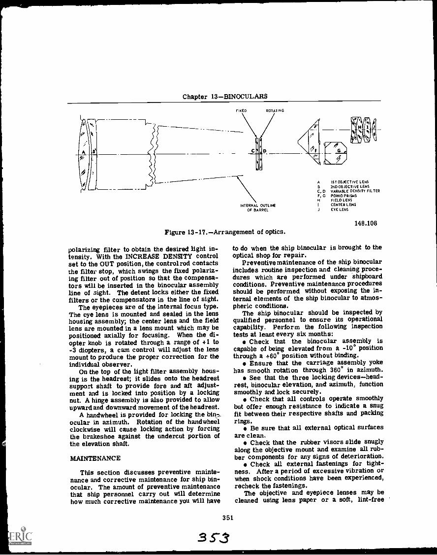
Chapter 13BINOCULARS
IXED ROTATING
INTERNAL OUTLINEOF BARREL
Figure 13-17.Arrangement of optics.
polarizing filter to obtain the desired light in-tensity. With the INCREASE DENSITY controlset to the OUT position, the control rod contactsthe filter stop, which swings the fixed polariz-ing filter out of position so that the compensa-tors will be inserted in the binocular assemblyline of sight. The detent locks either the fixedfilters or the compensators in the line of sight.
The eyepieces are of the internal focus type.The eye lens is mounted and sealed in the lenshousing assembly; the center lens and the fieldlens are mounted in a lens mount which may bepositioned axially for focusing. When the di-opter knob is rotated through a range of +1 to-3 diopters, a cam control will adjust the lensmount to produce the proper correction for theindividual observer.
On the top of the light filter assembly hous-ing is the headrest; it slides onto the headrestsupport shaft to provide fore and aft adjust-ment and is locked into position by a lockingnut. A hinge assembly is also provided to allowupward and downward movement of the headrest.
A handwheel is provided for locking the bin....ocular in azimuth. Rotation of the handwheelclockwise will cause locking action by forcingthe brakeshoe against the undercut portion ofthe elevation shaft.
MAINTENANCE
This section discusses preventive mainte-nance and corrective maintenance for ship bin-ocular. The amount of preventive maintenancethat ship personnel carry out will determinehow much corrective maintenance you will have
351
3 S-3
A 1ST OBJECTIVE LENSB 2ND OBJECTIVE LENSC, D VARIABLE DENSITY FILTERF, G PORRO PRISMS
FIELD LENSI CENTER LENSJ EYE LENS
148.108
to do when the ship binocular is brought to theoptical shop for repair.
Preventive maintenance of the ship binocularincludes routine inspection and cleaning proce-dures which are performed under shipboardconditions. Preventive maintenance proceduresshould be performed without exposing the in-ternal elements of the ship binocular to atmos-pheric conditions.
The ship binocular should be inspected byqualified personnel to ensure its operationalcapability. Perform the following inspectiontests at least every six months:
Check that the binocular assembly iscapable of being elevated from a -10° positionthrough a +60° position without binding.
Ensure that the carriage assembly yokehas smooth rotation through 360° in azimuth.
See that the three locking deviceshead-rest, binocular elevation, and azimuth, functionsmoothly and lock securely.
Check that all controls operate smoothlybut offer enough resistance to indicate a snugfit between their respective shafts and packingrings.
Be sure that all external optical surfacesare clean.
Check that the rubber visors slide snuglyalong the objective mount and examine all rub-ber components for any signs of deterioration.
Check all external fastenings for tight-ness. After a period of excessive vibration orwhen shock conditions have been experienced,recheck the fastenings.
The objective and eyepiece lenses may becleaned using lens paper or a soft, lint-free
OPTICALMAN 3 & 2
cloth which may be moistened with alcohol toremove grease. Unnecessary cleaning shouldbe avoided. Wipe metal surfaces to removeaccumulation of salt or dirt. To remove greaseand oil from the rubber components, wash themwith a mild soap and water solution. Note:Rubber will deteriorate if not kept dry.
Two types of fogging (external and internal)may be encountered when using the ship binocu-lar. External fogging is a temporary conditionthat will disappear as the lens surface becomeswarmer. To immediately remedy this condi-tion, wipe the eyepiece and objective lenseswith lens paper. Internal fogging indicates thata seal has been impaired at some point, allow-ing water vapor to enter the binocular. If in-ternal fogging occurs, the binocular will haveto be taken to the optical shop for repairs andrecharging with dry nitrogen. (The proce-dure for recharging will be given later in thischapter.)
The overhaul of the ship binocular will beperformed ONLY in an optical repair shopwhere adequate facilities and equipment foroverhaul, repair, and collimation are available.The ship binocular should be overhauled onlywhen necessary due to a malfunction of movingparts, separation of cemented lenses, a breakin a seal allowing water vapor or dirt to enterthe binocular assembly, or destruction or mis-alignment of optical parts.
If a seal has been broken, it will be neces-sary to disassemble the binocular to the extentrequired to clean and dry all optical and me-chanical parts. Inspection and replacement ofall packing rings, and gaskets as necessary,should be accomplished during the overhaulprocedures. Immediately following the re-assembly procedures, the binocular assemblyshould be charged with dry nitrogen.
The following checklist may be used to de-termine the extent of repairs necessary to re-turn a damaged ship binocular to satisfactoryoperating condition:
Inspect the exterior of the binocular as-sembly for physical damage.
Ensure that the interocular handle oper-ates smoothly without binding or excessivelooseness.
Check for proper operation of the IN-CREASE DENSITY control.
View a distant object (approximately 1/2mile) and adjust focus control of eyepieceto ensure proper definition for each eye. Ifproper definitions cannot be obtained, either
an adjustment of the diopter controls is neces-sary or the optics of the binocular assemblyare defective.
Check that the elevation, azimuth, heightmechanism, and locks operate smoothly.
Check for internal gas pressure.
Disassembly
In order for the reader to become familiarwith format used in most NAVSHIPS TechnicalManuals, the disassembly procedure and theillustration for the ship-mounted binoculars islisted in the same step-by-step form.
Before disassembling any component fromthe binocular assembly, open the OUTLETscrew (top of right barrel) to release the in-ternal pressure if parts within the binocularseal are to be removed.
Disassemble the binocular assembly as fol-lows (refer to fig. 13-18):
1. To disassemble the objective lens assem-bly remove ring (56) and the preformed packing(62) from the objective lens housing.
2. Unscrew ring (57) and remove spacer (58)from the crown objective lens, and removecrown lens (59) and wrap in lens paper andstore in a safe place.
3. Remove spacer (60) and objective flintlens (61) from housing and also wrap flint lensin lens paper and store in a safe place.
NOTE
If both objective lenses from bothbarrels are removed at the sametime, it is advisable to keep thelenses and other components of theleft and right lens mounting ar-rangements separated and identi-fied so that they may be replacedproperly.
4. Next remove the optics housing from thelight filter housing. First remove retainingring (73) that secures the light filter assemblyto the optics housing.
5. Next detach spring (84) from the detentarm.
6. Now remove the light filter assemblyfrom the optics housing.
7. Remove screws to detach retaining platefrom filter housing.
8. Remove washers (78 and 81), polarizingfilters (79), and compensating filters (82) fromhousing.
352
355
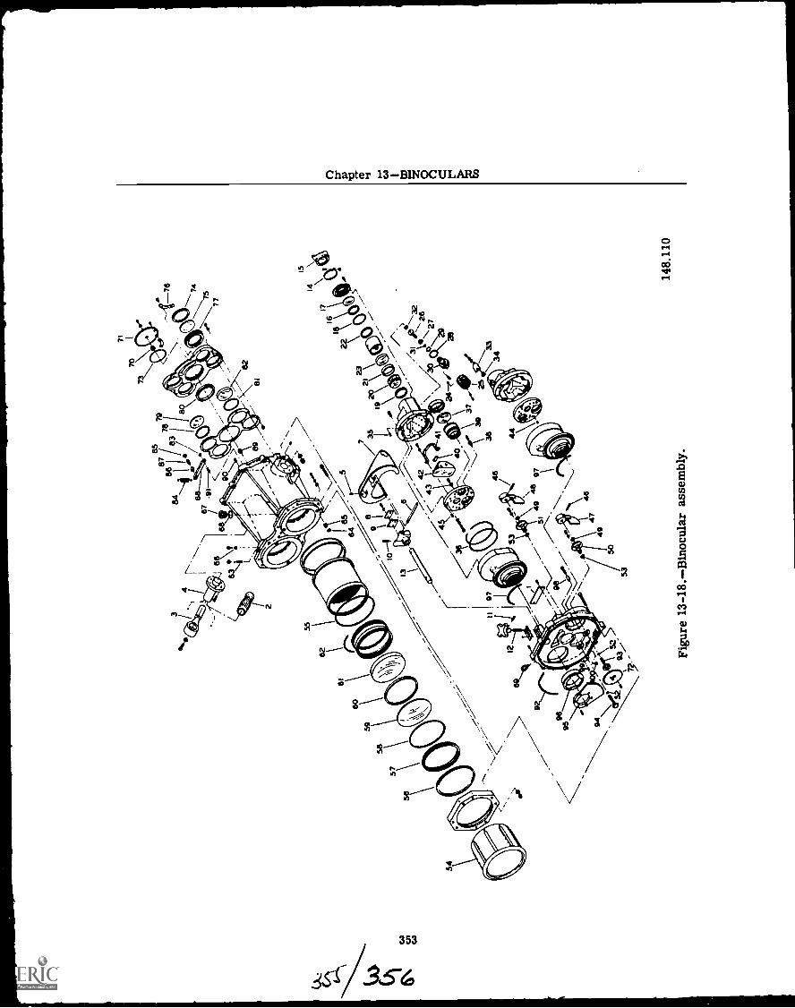
OPTICALMAN 3 & 2
9. Remove screws to detach clamp (76), andgear assembly (70 and 71) from filter housing.
10. Remove retaining rings (74), and polariz-ing filters (75) from filter housing.
11. Now separate the prism housing from thelight filter housing. First remove screws se-curing sector gears (95) and sleeve bearing (96)allowing separation of the two prism housingsfrom the light filter housing.
12. To disassemble the INCREASE DENSITYcontrol (47) and the interocular knob assem-blies (48) follow the order of index numbers infigure 13-18.
13. Refer to figure 13-18 and remove the ap-propriate screws to separate the prism housingfrom the eyepiece housing.
14. Now disassemble the prism and plate as-semblies by removing the appropriate screwsto separate the prism and plate assembly fromthe housing.
15. Remove items (37 through 39) from prismplate.
16. Loosen screws and remove retaining strap(41) and clamp pad (40).
17. Remove prisms (42) from support plate.Wrap prisms in lens paper and store in safeplace.
18. Now disassemble the left and right eye-piece housing assemblies. Loosen setscrewand remove diopter knob (25).
19. Next loosen screws and remove bearingsleeve (30) and items (27 through 29, 31, and32).
20. Disassemble items (16 through 25) fol-lowing the order of index numbers shown infigure 13-18.
Disassembly of the ship binocular is nowcompleted. The next step is to repair or re-place parts that are worn or damaged.
Reassembly
Reassembly procedures are essentially thereverse of disassembly. Old packing should bereplaced and parts which were sealed withglyptal should be carefully cleaned before re-sealing with fresh compound.
Match-marks noted or made at disassemblywill assist in proper orientation and mating ofparts. Extreme care should be exercised toprevent oil or moisture from contacting partsto be mounted inside the binocular assembly.
To reassemble the binocular assembly, dothe following:
354
1. Apply a bead of Navy approved sealingcompound, approximately 3/32 inch in diame-ter, to junction of outside diameter of crownobjective lens (59) and housing.
2. Assemble spacer (58) and ring (57) incell housing. Ring shall be installed to ensuremetal to glass contact between items 58 and 59.
3. Apply a thin film of Navy approved highvacuum grease to all preformed packing.
4. Apply a thin film of adhesive to the hous-ing shoulder and eyepiece lens (17).
5. Press fit filter housing shaft (89), groovedpin (90), and shouldered pin (91) into opticshousing assembly.
6. Stake shoulder pin (87) to detent arm (88).7. Press fit bearing sleeve (70) into spur
gear (71).8. Press two straight pins (44 and 45) into
right-hand support plate.9. Apply approved cement to items 40 and
41.10. Press fit two straight headless pins (99)
into binocular housing to a height of 3/16inch.
11. Press knob stop cushion (100) into bin-ocular housing.
12. Align hole of interocular knob (48) withhole of gear shaft (94) and insert a dummy pin.Check that end play of gear shaft is between0.002 and 0.005 inch. If it is not, shim with flatwasher (49) to obtain desired end play. Removedummy pin and press in groove pin (46).
13. Align hole of filter knob (47) with hole ofadjustment shaft (93) and insert a dummy pin.Check that adjustment shaft end play is between0.002 and 0.005 inch. If it is not, shim with flatwasher (49) to obtain required end play.
14. When assembling focusing mechanism in-sert assembly consisting of bearing sleeve (30),diopter shaft, and cam control (32) into dioptershaft bore of housing (with eyepiece lens as-sembly, 19 through 22, secured in the housing).With the flange of the bearing sleeve (30) heldsecurely against the eyepiece lens housing,measure end play of shaft (between shaft as-sembly, cam control, and eyepiece lens hous-ing, 18 through 22). End play should be between0.001 and 0.005 inch. Disassemble and shimbetween bearing sleeve and diopter shaft withflat washer (27) to obtain desired end play.
15. To set diopter knob to correct mountingposition with respect to its diopter scale andthe reference mark on the eyepiece casting, itwill be necessary to establish the zero diopterposition for each eyepiece.
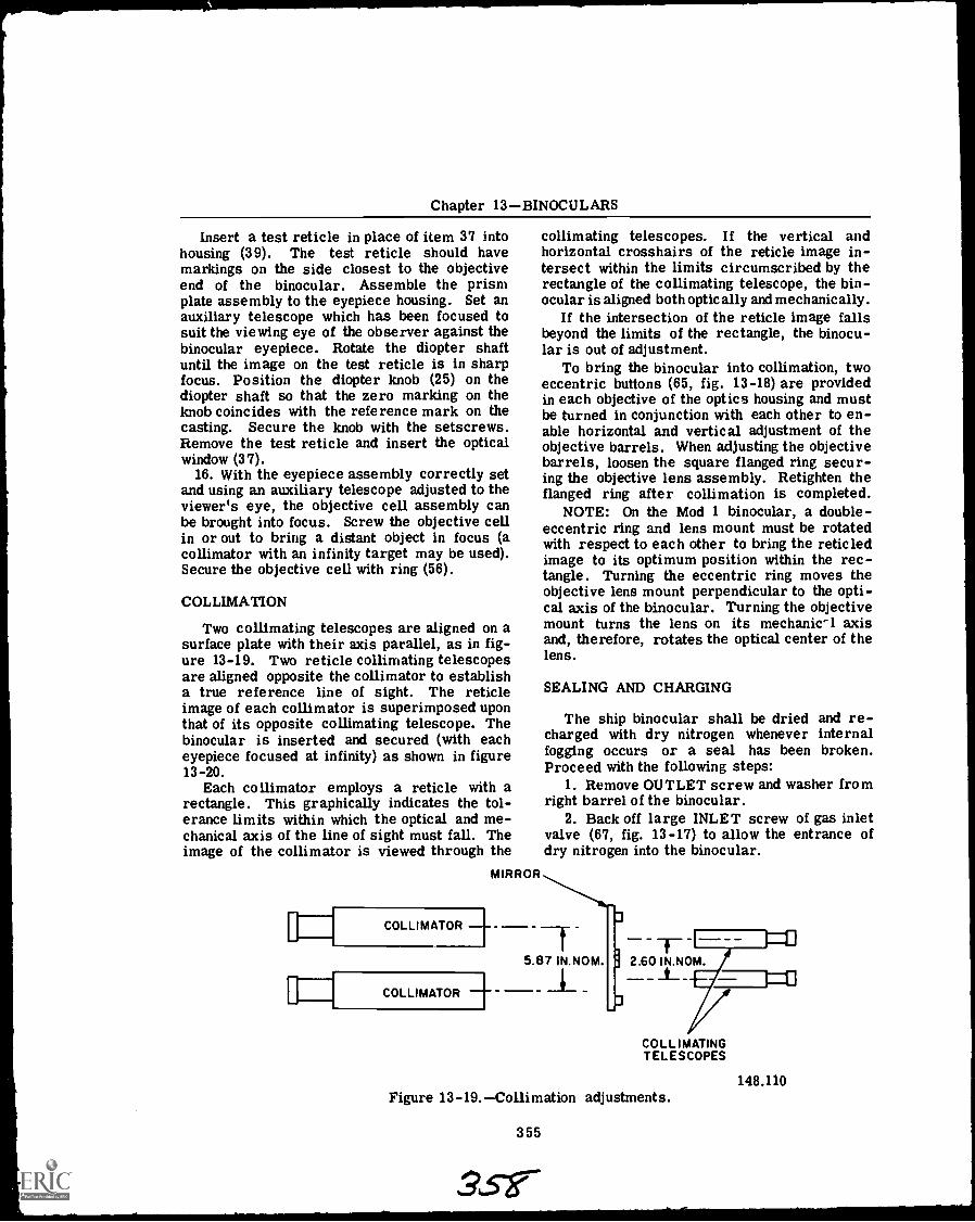
Chapter 13BINOCULARS
Insert a test reticle in place of item 37 intohousing (39). The test reticle should havemarkings on the side closest to the objectiveend of the binocular. Assemble the prismplate assembly to the eyepiece housing. Set anauxiliary telescope which has been focused tosuit the viewing eye of the observer against thebinocular eyepiece. Rotate the diopter shaftuntil the image on the test reticle is in sharpfocus. Position the diopter knob (25) on thediopter shaft so that the zero marking on theknob coincides with the reference mark on thecasting. Secure the knob with the setscrews.Remove the test reticle and insert the opticalwindow (37).
16. With the eyepiece assembly correctly setand using an auxiliary telescope adjusted to theviewer's eye, the objective cell assembly canbe brought into focus. Screw the objective cellin or out to bring a distant object in focus (acollimator with an infinity target may be used).Secure the objective cell with ring (56).
COLLIMATION
Two collimating telescopes are aligned on asurface plate with their axis parallel, as in fig-ure 13-19. Two reticle collimating telescopesare aligned opposite the collimator to establisha true reference line of sight. The reticleimage of each collimator is superimposed uponthat of its opposite collimating telescope. Thebinocular is inserted and secured (with eacheyepiece focused at infinity) as shown in figure13-20.
Each collimator employs a reticle with arectangle. This graphically indicates the tol-erance limits within which the optical and me-chanical axis of the line of sight must fall. Theimage of the collimator is viewed through the
collimating telescopes. If the vertical andhorizontal crosshairs of the reticle image in-tersect within the limits circumscribed by therectangle of the collimating telescope, the bin-ocular is aligned both optically and mechanically.
If the intersection of the reticle image fallsbeyond the limits of the rectangle, the binocu-lar is out of adjustment.
To bring the binocular into collimation, twoeccentric buttons (65, fig. 13-18) are providedin each objective of the optics housing and mustbe turned in conjunction with each other to en-able horizontal and vertical adjustment of theobjective barrels. When adjusting the objectivebarrels, loosen the square flanged ring secur-ing the objective lens assembly. Retighten theflanged ring after collimation is completed.
NOTE: On the Mod 1 binocular, a double-eccentric ring and lens mount must be rotatedwith respect to each other to bring the reticledimage to its optimum position within the rec-tangle. Turning the eccentric ring moves theobjective lens mount perpendicular to the opti-cal axis of the binocular. Turning the objectivemount turns the lens on its mechanic-1 axisand, therefore, rotates the optical center of thelens.
SEALING AND CHARGING
The ship binocular shall be dried and re-charged with dry nitrogen whenever internalfogging occurs or a seal has been broken.Proceed with the following steps:
1. Remove OUTLET screw and washer fromright barrel of the binocular.
2. Back off large INLET screw of gas inletvalve (67, fig. 13-17) to allow the entrance ofdry nitrogen into the binocular.
COLLIMATOR --f -
COLLIMATOR
2.60 IN.NOM._t_
COLLIMATINGTELESCOPES
Figure 13-19.Collimation adjustments.
355
148.110
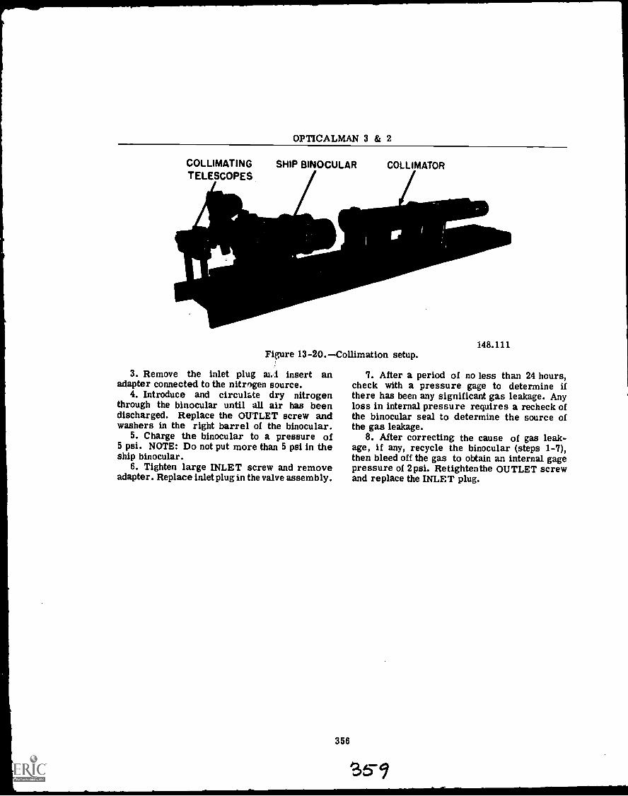
OPTICALMAN 3 & 2
COLLIMATINGTELESCOPES
SHIP BINOCULAR COLLIMATOR
Figure 13-20.Collimation setup.
3. Remove the inlet plug aLl insert anadapter connected to the nitrogen source.
4. Introduce and circulate dry nitrogenthrough the binocular until all air has beendischarged. Replace the OUTLET screw andwashers in the right barrel of the binocular.
5. Charge the binocular to a pressure of5 psi. NOTE: Do not put more than 5 psi in theship binocular.
6. Tighten large INLET screw and removeadapter. Replace inlet plug in the valve assembly.
356
148.111
7. After a period of no less than 24 hours,check with a pressure gage to determine ifthere has been any significant gas leakage. Anyloss in internal pressure requires a recheck ofthe binocular seal to determine the source ofthe gas leakage.
8. After correcting the cause of gas leak-age, if any, recycle the binocular (steps 1-7),then bleed off the gas to obtain an internal gagepressure of 2 psi. Retighten the OUTLET screwand replace the INLET plug.
S5-9
CHAPTER 14
SUBMARINE PERISCOPES
Optically, the submarine periscope is nomore complicated than a large gunsight. Butbecause the periscope has several functionsinstead of just one, and because its designerhas had to solve a number of special problems,the mechanical systems are intricate.
The earliest submarines were built withoutprovision for periscopes and therefore, whensubmerged, were forced to grope their wayblindly.
In 1854, Marie Davey, a Frenchman, de-signed a sight tube for a submarine. The tubecontained two mirrors, one above the other, ata 45° angle and facing in opposite directions.These mirrors, while providing some degree ofsight to the submerged ship, were faulty at best;in 1872, prisms were substituted for mirrors.
Before the War Between the States, the sub-marine had not had a place among the ships ofnaval warfare. An American, Thomas H.Doughty, USN, was the inventor of the originalperiscope. Doughty's invention was not theresult of study and research but grew out ofnecessity. During the campaign of the RedRiver, while he was serving aboard the monitorOsage, Confederate cavalry on the banks of theriver kept up a steady series of surprise attacksupon the Union ships, which had no way of see-ing over the banks. This led Doughty to seeksome new method of watching the shores. Hetook a piece of lead pipe, fitted it with mirrorsat either end, and ran it up through the turret.This makeshift periscope provided sight for thecrew of the Osage.
The earliest periscope, other than a collaps-ible one designed late in the nineteenth centuryby Simon Lake and known as an omniscope orskalomniscope, was a fixed tube. Soon, how-ever,provision was made to allow the tube to beraised and turned by hand. This was fairly sat-isfactory when the boat was traveling at a lowrate of speed, but with increased speed the pres-sure was apt to bend the tube and throw theimage out of line. Improved design resulted ina double tube, the outer one to resist pressureand the inner one to house the lens systems.
357
DESIGN DESIGNATION
To ensure a uniform method of definitionson submarines, a standard system of nomencla-ture is used in all correspondence, specifica-tions, and plans relating to such instruments.
The periscope nearest the bow is called theNo. 1 periscope. This is normally the observa-tion periscope. The next periscope aft of theNo. 1 periscope is called the No. 2 periscope.This is normally the attack periscope. In somenewer type submarines, the periscopes aremounted side by side instead of fore and aft.In these submarines,the starboard periscope isNo. 1, normally the attack periscope, and theport periscope is No. 2, normally the observa-tion periscope.
The term "ALTIPERISCOPE" is applied toinstruments having the combined qualities ofaltiscopes and periscopes; they are also some-times called altiscope-periscopes and alti-azimuth instruments. With the altiperiscope,the upper prism is movable on a horizontal axis,so that by turning it, the observer can raise orlower his line of sight.
The term "UNIFOCAL" designates an in-strument with only one magnification; a BI-FOCAL instrument offers a choice of two mag-nifications. Most of the periscopes in use todayare of the bifocal type.
The NIGHT PERISCOPE is especially de-signed for use in dim light; it has high lighttransmission and a large exit pupil.
An ATTACK PERISCOPE is designed toallow the submarine to get as close as possibleto the enemy without being seen. The diameterof its head sectionthe part that rises abovethe surfaceis reduced to an absolute minimum.
The term "AZIMUTH CIRCLE," as appliedto a periscope, refers to the graduated ringmounted below the packing gland in the conningtower. This is true except for periscopes whichincorporate the electrical and electronic (E andE) adapter; on this type of periscope the azimuthcircle is on the E and E adapter. The azimuthcircle is used for taking bearings through theperiscope.
a a
OPTICALMAN 3 & 2
Submarine periscopes are under the tech-nical cognizance of the NavShipsSysCom. Theyhave no Mark numbers. Instead, each separatedesign, or modification of a design, is assigneda DESIGN DESIGNATION made up of the follow-ing symbols:
A serial number for each design, ormodification; these numbers are assigned byBuShips.
A letter indicating the manufacturer, us-ing this code:
KKollmorgen.S Sperry.A letter showing the type of instrument:Abifocal altiperiscope.Hhigh-power altiperiscope.N night periscope.A number showing the length of the optical
system, in feet (to the nearest foot).The letter T may be used to show that the
optics have been treated (by filming) to increasetheir light transmission.
If the outside diameter of the upper headsection is less than two inches, this diameter,in inches, is added to the design designation,separated from the preceding symbols by adiagonal mark.
If the instrument is an altiperiscope, andif its field of view can be raised enough to in-clude the zenith, the letters HA (meaning highangle) are added to the design designation.
Here is a typical design designation:
91KA4OT /1.414HA
Decoded, that means:
Serial number of thedesign
The manufacturer,Kollmorgen
91 K A 40 T 1.414 HA
Type of instrument:bifocal altiperiscope
Length of the opticalsystem, in feet
Coated optics
Outside diameter, ininches, of the upperhead section
High angle
Each individual instrument is assigned aregistry number (the same as a serial numberon other instruments). You will find the regis-try number cut or stamped on each periscope atits eyepiece end, and on all of its detachablefittings, such as the training handles. On theeyepiece box of each periscope you will find anameplate, which shows the design designation,the registry number, and some of the opticalcharacteristics, such as magnification and fieldof view.
THEORY AND DESIGN
Basically the periscope is a tube, with re-flecting elements at the top and bottom,to raisethe observer's line of sight. But the actualdesign is not that simple. The periscopedesigner must solve several special problemsthat are not encountered in the design of otheroptical instruments. He must make a compro-mise between conflicting requirements. Hereare some of the problems:
First of all, the periscope has to be rela-tively long, as you can see in figure 14-1. Itmust be long enough to rise above the surfacewhile the submarine is still far enough below tobe invisible to surface craft. Optical lengthsof periscopes in service run to 40 feet or more.
Another important requirement is that theupper head sectionthe part that sticks out ofthe watermust be as slender as possible, toescape detection by the enemy, and to create aminimum wake. The wake of the periscope, ifseen by the enemy, would not only reveal thesubmarine's presence, but also would indicateits course.
When the periscope is not in use, it islowered, for protection, into a well (fig. 14-1).But when the submarine is maneuvering intoattack position, it will use its periscope, fullyelevated, while underway submerged. Duringthat time, the periscope will be dragged throughthe water at high speeds. The periscope, inspite of its slender construction, must be rigidenough to resist the bending effect of the waterpressure that results from its own drag. Theoptical system must be so designed that thebending effect will not distort or displace thetarget image.
Another requirement is that the periscopemust be able to scan the whole horizon; it mustbe provided with some means for sweepingthrough 360 degrees in azimuth. With a modern
358
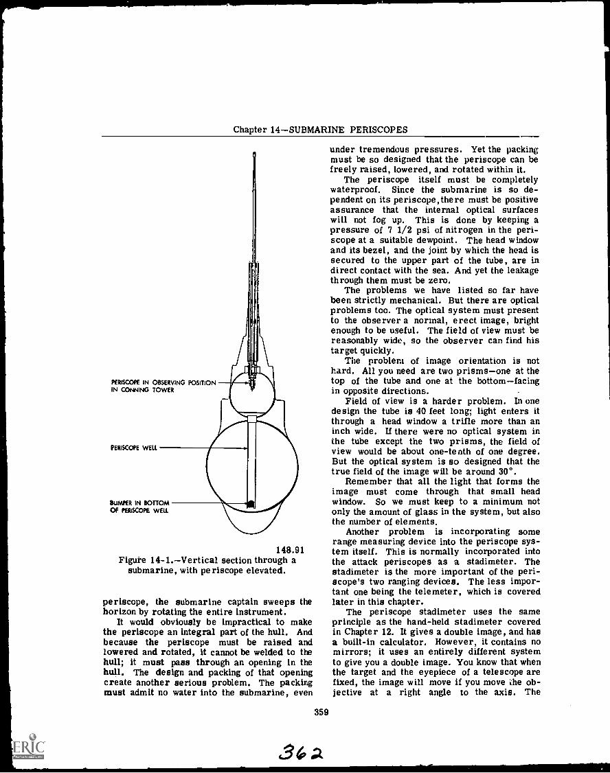
Chapter 14SUBMARINE PERISCOPES
PERISCOPE IN OBSERVING POSITIONIN CONNING TOWER
PERISCOPE WELL
BUMPER IN BOTTOMOF PERISCOPE WELL
148.91Figuke 14-1.Vertical section through a
submarine, with periscope elevated.
periscope, the submarine captain sweeps thehorizon by rotating the entire instrument.
It would obviously be impractical to makethe periscope an integral part of the hull. Andbecause the periscope must be raised andlowered and rotated, it cannot be welded to thehull; it must pass through an opening in thehull. The design and packing of that openingcreate another serious problem. The packingmust admit no water into the submarine, even
359
436A
under tremendous pressures. Yet the packingmust be so designed that the periscope can befreely raised, lowered, and rotated within it.
The periscope itself must be completelywaterproof. Since the submarine is so de-pendent on its periscope,there must be positiveassurance that the internal optical surfaceswill not fog up. This is done by keeping apressure of 7 1/2 psi of nitrogen in the peri-scope at a suitable dewpoint. The head windowand its bezel, and the joint by which the head issecured to the upper part of the tube, are indirect contact with the sea. And yet the leakagethrough them must be zero.
The problems we have listed so far havebeen strictly mechanical. But there are opticalproblems too. The optical system must presentto the observer a normal, erect image, brightenough to be useful. The field of view must bereasonably wide, so the observer can find histarget quickly.
The problem of image orientation is nothard. All you need are two prismsone at thetop of the tube and one at the bottomfacingin opposite directions.
Field of view is a harder problem. In onedesign the tube is 40 feet long; light enters itthrough a head window a trifle more than aninch wide. If there were no optical system inthe tube except the two prisms, the field ofview would be about one-tenth of one degree.But the optical system is so designed that thetrue field of the image will be around 30°.
Remember that all the light that forms theimage must come through that small headwindow. So we must keep to a minimum notonly the amount of glass in the system, but alsothe number of elements.
Another problem is incorporating somerange measuring device into the periscope sys-tem itself. This is normally incorporated intothe attack periscopes as a stadimeter. Thestadimeter is the more important of the peri-scope's two ranging devices. The less impor-tant one being the telemeter, which is coveredlater in this chapter.
The periscope stadimeter uses the sameprinciple as the hand-held stadimeter coveredin Chapter 12. It gives a double image, and hasa built-in calculator. However, it contains nomirrors; it uses an entirely different systemto give you a double image. You know that whenthe target and the eyepiece of a telescope arefixed, the image will move if you move the ob-jective at a right angle to the axis. The
OPTICALMAN 3 & 2
periscope stadimeter uses this principle to dis-place the two parts of a double image. The ob-jective lens of the lower main telescope isSPLIT VERTICALLY into two halves, with asmall space between them.
To use the stadimeter, you first set theactual target height on the dial. Then, as youturn the ranging knob, half the lower main ob-jective rises (relative to the target image), andthe other half is lowered. As a result, you willsee adouble image of the target, and the fartheryou turn the ranging knob, the farther the twoimages will separate. When you bring the topof one image into line with the bottom of theother, you can read the range on the stadimeterdial.
OPTICAL DESIGN
We will consider first the principal opticalproblem; securing a true field of useful widthin spite of the small head window and the longnarrow tube. The periscope designer solvesthe problem by combining simple optical sys-tems such as the astronomical telescope.
As astronomical telescope produces an in-verted image. It has only two principalelementsan objective and an eyepiece; this isa valuable feature for use in a periscope, sincewe are trying to hold the number of elementsto a minimum. We need not worry about theinverted image if we use two astronomicaltelescopes in series. The first will invert theimage; the second will reinvert it.
In any telescope, the magnifying power isequal to the focal length of the objective dividedby the focal length of the eyepiece; and themagnifying power is equal to the apparent fielddivided by the true field. For example, sup-pose that an object, when viewed by the nakedeye, subtends an angle of 5°. The same object,when viewed through a telescope, appears tosubtend an angle of 30°. You know at once thatthe magnifying power of the telescope is 6 X.
Our problem is to take a fairly wide truefield and reduce it to a narrow apparent field,so that the image will travel as far as possibledown the periscope tube. You have probablylooked through the wrong end of a telescope atsome time or other. You remember that theobjects you saw looked very small and far off(and consequently the true field of view wasmuch larger than the apparent field).
The main optical system of the subma-rine periscope consists of two astronomical
360
telescopes. We call them the UPPER MAINTELESCOPE and the LOWER MAIN TELE-SCOPE. The upper main telescope is back-wardsits eyepiece is at the top of the tube.Suppose we want a true field of 30°. And sup-pose that our upper main telescope has a mag-nifying power of 15 Xthe focal length of itsobjective is 15 times that of its eyepiece. Sincethe upper telescope is backwards, its actual mag-nifying power will be 1/15 X, and its apparentfield will be 1/15 the true field. Thus our 30°true field will be reduced to only 2° as it leavesthe upper telescope, and that narrow beam canpass down the periscope tube for a consider-able distance.
We defined the objective as the lens nearestthe target. If we apply that definition to theupper main telescope of the periscope, then it isnot really backwards. It is a normal telescopewith a short-focus objective and a relativelylong-focus eyepiece. But we are accustomedto working with telescopes whose magnifyingpower is more than one. We are used to theidea that the short-focus lens is the eyepiece,and the long-focus lens is the objective. Themen who work with periscopes hold on to thatideathey call the upper lens of the upper tele-scope the eyepiece, even though there is no eyewithin 40 feet of it. We will go along with them.Keep that in mind so you will not be confused.
The lower main telescope is in the normalpositionits objective is toward the target, andthe focal length of its objective is greater thanthat of its eyepiece. Its magnifying power,therefore, is greater than one. In the examplegiven, we assumed that the upper main tele-scope had a magnifying power of 1/15 X. Now,if we give the lower telescope a magnifyingpower of 15 X, the magnifying power of the twotogether will be:
1/15 x 15 = 1
The upper telescope reduced the true field of30° to an apparent field of 2°. The lower tele-scope, with a magnifying power of 15 X, willbring the field back to an apparent field of 30°,equal to the true field of the instrument.
In figure 14-2 you can follow the path of lightrays through the periscope we have described.Part A shows the action of the two telescopesalone; in part B we have added the two prisms,to bend the line of sight twice through 90°. Inthe figure, the broken line represents the opti-cal axis. The two solid lines show the path of
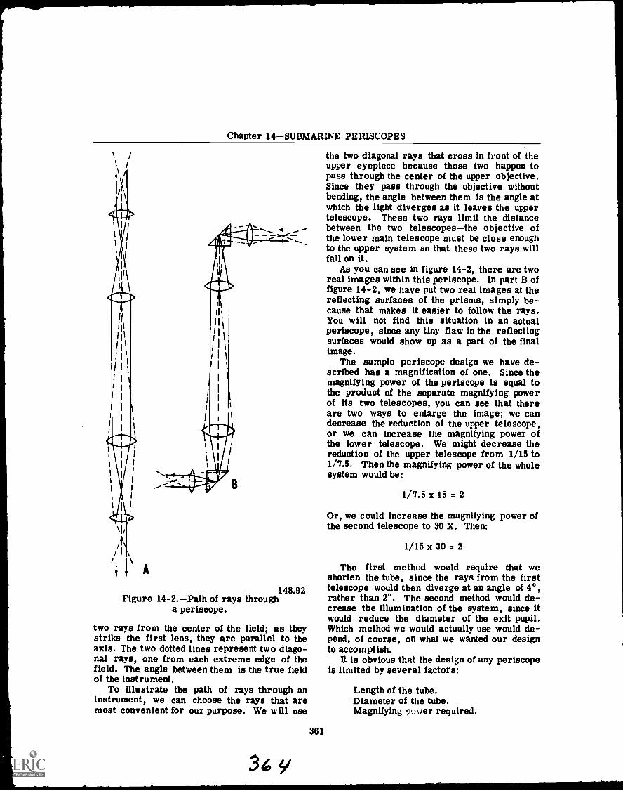
Chapter 14SUBMARINE PERISCOPES
148.92Figure 14-2.Path of rays through
a periscope.
two rays from the center of the field; as theystrike the first lens, they are parallel to theaxis. The two dotted lines represent two diago-nal rays, one from each extreme edge of thefield. The angle between them is the true fieldof the instrument.
To illustrate the path of rays through aninstrument, we can choose the rays that aremost convenient for our purpose. We will use
361
y
the two diagonal rays that cross in front of theupper eyepiece because those two happen topass through the center of the upper objective.Since they pass through the objective withoutbending, the angle between them is the angle atwhich the light diverges as it leaves the uppertelescope. These two rays limit the distancebetween the two telescopesthe objective ofthe lower main telescope must be close enoughto the upper system so that these two rays willfall on it.
As you can see in figure 14-2, there are tworeal images within this periscope. In part B offigure 14-2, we have put two real images at thereflecting surfaces of the prisms, simply be-cause that makes it easier to follow the rays.You will not find this situation in an actualperiscope, since any tiny flaw in the reflectingsurfaces would show up as a part of the finalimage.
The sample periscope design we have de-scribed has a magnification of one. Since themagnifying power of the periscope is equal tothe product of the separate magnifying powerof its two telescopes, you can see that thereare two ways to enlarge the image; we candecrease the reduction of the upper telescope,or we can increase the magnifying power ofthe lower telescope. We might decrease thereduction of the upper telescope from 1/15 to1/7.5. Then the magnifying power of the wholesystem would be:
1/7.5 x 15 = 2
Or, we could increase the magnifying power ofthe second telescope to 30 X. Then:
1/15 x 30 = 2
The first method would require that weshorten the tube, since the rays from the firsttelescope would then diverge at an angle of 4°,rather than 2°. The second method would de-crease the illumination of the system, since itwould reduce the diameter of the exit pupil.Which method we would actually use would de-pend, of course, on what we wanted our designto accomplish.
It is obvious that the design of any periscopeis limited by several factors:
Length of the tube.Diameter of the tube.Magnifying nower required.
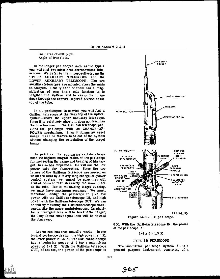
OPTICALMAN 3 & 2
Diameter of exit pupil.Angle of true field.
In the longer periscopes such as the type 2you will find two additional astronomical tele-scopes. We refer to them, respectively, as theUPPER AUXILIARY TELESCOPE and theLOWER AUXILIARY TELESCOPE. The twoauxiliary telescopes are mounted above the maintelescopes. Usually each of them has a mag-nification of one; their only function is tolengthen the system and to carry the imagedown through the narrow, tapered section at thetop of the tube.
In all periscopes in service you will find aGalilean telescope at the very top of the opticalsystemabove the upper auxiliary telescope.Since it is relatively short, it does not lengthenthe tube too much. The Galilean telescope pro-vides the periscope with its CHANGE-OF-POWER mechanism. Since it forms an erectimage, it can be thrown in or out of the systemwithout changing the orientation of the targetimage.
In practice, the submarine captain alwaysuses the highest magnification of the periscopefor measuring the range and bearing of his tar-get, to aim his torpedoes. He will use the lowpower only for observation. Since the twolenses of the Galilean telescope are moved onor off the axis by a fairly long change-of-powercontrol system, we cannot be sure they willalways come to rest in exactly the same placeon the axis. But in measuring target bearing,we must have maximum accuracy. We must,therefore, design the periscope to give lowpower with the Galilean telescope IN, and highpower with the Galilean telescope OUT. We cando that by mounting the Galilean telescope back-wards,like the upper maintelescope. Its short-focus divergent lens will be toward the target;its long-focus convergent lens will be towardthe observer.
Let us see how that actually works. In onetypical periscope design, the high power is 6 X;the lower power is 1.5 X. The Galilean telescopehas a reducing power of 4 (or a magnifyingpower of 1/4 X). With the Galilean telescopeOUT, of course, the power of the periscope is
362
HEAD SECTION
OUTER TUBE
ANTENNAAS/622
BLINDERATTACHMENT
EYEPIECE &FACEPLATE
RIGHTTRAINING
SUN FILTER HANDLERELEASEBUTTON
OPTICAL WINDOW
ANTENNA
RADAR ANTENNA
GRIP FORLINE OF
FOCUSING SIGHTKNOB ELEVATION
LEFTTRAINING
HANOLE
GRIP FORMAGNIFICATION
CHANGE POWERASSISTSWITCH
EYEPIECE BOX
TELEMETERRHEOSTAT
KNOB
E 8 E AOAPTER
148.94:.95Figure 14-3.-8-B periscope.
6 X. With the Galilean telescope IN, the powerof the periscope is:
1/4 x 6 = 1.5 X
TYPE 8B PERISCOPE
The submarine periscope system 8B is ageneral purpose instrument consisting of a
Chapter 14SUBMARINE PERISCOPES
type 8B periscope, (fig. 14-3), an Electrical andElectronic (E and E) Adapter, and several exter-nally mounted control or connection boss.
The type 8B periscope is a night serviceinstrument of 36-foot optical length and '7 1/2-inch outer diameter, exclusive of the eyepieceand faceplate assembly, handles, and other con-trols on the eyepiece box. All electrical con-nections to the periscope are made through theE and E adapter.
The optical system in the 8B periscope c..n-tains a tilting head prism that is capable ofelevating the line of sight 60° above the hori-zontal, and 10° below the horizontal. A sunfilter located in the head section may be movedin or out of the optical path while the peri-scope is in high power. At night the telemetermay be red-illuminated for better observation.The re are also attachments provided for mount-ing a camera adapter to the eyepiece box for tak-ing photos while the submarine is submerged.
The 8B periscope also contains a means ofde-fogging and de-icing the head window of theperiscope by use of a heated head window.
The men on submarines at times have tostand watch at the periscope when the sub-marine is submerged. To make this job a littleeasier the periscope system incorporates atraining torquer, which is operated from theright training handle and is used to aid in train-ing the periscope. This is done by use of amotor, which when turned on will help turn theperiscope. After about 15 minutes on watch,having to turn the periscope by hand would wearthe man out. With the power torquer to assisthim, this will not happen. The power torqueris to be used as an assist to help turn the peri-scope and is not to be used alone. If used cor-rectly, it will be like using power steering ina car.
The external casing of the periscope systemconsists of four main sections: the outer head,the outer tube, the eyepiece box, and the E andE adapter. The joints between the outer headand the outer tube and between the outer tubeand eyepiece box, consist of an "0" ring, abronze coupling, two setscrews, and a gasketseal. The outer tube itself is made out ofcorrosion-resisting steel.
The internal framework of the system con-sists of three main parts: the head skeleton,the body skeleton, and the eyepiece components.All of the internal optics are supported andpositioned by this framework. The shafts andlinkages from the eyepiece box, which are used
363
c3loG
to operate the mechanisms, are also supportedby the internal framework.
The optical system of the 8B periscope con-sists e three main components: the head as-sembly, optical relays, and the eyepiece andfaceplate assc mbly. The head assembly con-tains a tilting prism, which is operated byrotating shafts and gearing from the left train-ing haalle. A 2 speed and a 36-speed synchroare also incorporated, for precision measure-ment of the relative elevation of the line ofsight.
For low-poll :r operation, movement of theright training handy; mechanically causes twolenses (Galilean cubes) to rotate into positionjust below the head prism. These lenses actas a reverse tP.i;scope to decrease the per? -scope magnification.
When the periscope is in the high poweroperating position, further movement of theright training Handle causes a sun filter torotate into place. The focusing knob on the sideof thr- eyepiece box, ehown in figure 14-3,mechanically moves the focusing erector lensnear the base of the tube. This knob providesfor the + "I.5 to - 3.0 dicpter focus range for theobserver, and also provides for camera focus.There is also a sextant switch located on theleft training handle, for taking sextant readingswhile submerged. A more detailed coverageof the submarine periscope can be found in theOM 1 and C training manual, and the NavShipsTechnical Manuals.
REMOVAL AND INSTALLATION
The illustrations and text in the followingsection will depict a Type 2 attack periscope;however, the general procedures discussed willapply to all types of submarine periscopes.
To remove a periscope from a submarineand transport it to the optical shop of a tender,follow these steps:
Removing a periscope from a submarinecan be done only in a sheltered harbor, sincerolling of either ship is likely to seriouslydamage the periscope. The submarine shouldbe moored alongside the tender on the sidefrom which it will be easiest to move the peri-scope into the optical shop. If there is a coverplate over the steady bearing of the submarine(at the top of the periscope opening), removethe plate.

OPTICALMAN 3 & 2
148.100Figure 14-4.Clamps and slings attached
to the outer tube.
CLAMPING
u Elevate the periscope high enough to attachthe slings. You will need free access to at least2 feet of the outer tube below the point wherethe taper section is joined to it.
Bolt a forged steel hoisting clamp aroundthe outer tube,at least 12 inches below the jointbetween the outer tube and the taper section.(The hoisting clamp is marked No. 2 in fig.14- The hoisting clamp should be lined withemery cloth with its smooth side next to theouter tube of the periscope. Since the frictionbetween the clamp and the outer tube must sup-port the weight of the periscope, do not try touse a clamp that fits poorly. And never use aclaim containing setscrews. Bolt one or twosafety clamps (No. 3 in fig. 14-4) to the outertube above the hoisting clamp. The safety
364
clamps will keep the periscope from slippingdownward within the hoisting clamp.
The slings must be long enough to clearthe periscope head, and they must be attachedto a spreader bar of sufficient width to keepthem from fouling the head. Put the hook ofthe lifting crane in the hook opening of thespreader bar, as in figure 14-4.
Raise the periscope to observing position,and transfer its weight to the lifting crane.
EXTERNAL FITTINGS
Now remove all parts of the periscope thatproject beyond the diameter of the outer tube.Figure 14-5 shows these parts. First, removethe two training handles by removing the fourhinge bracket bolts.
Remove the focusing knob assembly bytaking out four lockscrews.
Remove the color filter assembly by pull-ing outward on the two spring-actuated plungerknobs.
Remove the stadimeter housing.Remove the eyepiece attachments, which
are secured to anchor screw pins projectingfrom the eyepiece box.
Now check to be sure the lifting crane isholding the weight of the periscope. Slack offthe hoisting yoke.
Remove the lockscrews from the coverring, and unscrew the cover ring with a spannerwrench. Then remove the hoisting yoke body,the phosphor bronze locating collar, the lowerball bearing race, the ball bearings and re-tainer, and the upper ball bearing race. (Theseparts are identified in fig. 14-5.) Be especiallycareful to protect all these parts from dirtand grit.
Remove the split ring and the ring cover.Slack off the hull stuffing box gland.The periscope must be hoisted vertically;
before hoisting, check to be sure that the craneboom is directly above the periscope. Attacha hinged clamp with handles to the outer tubeabove the deck opening of the submarine. Whilethe crane is hoisting the periscope, use thehandles of the clamp to rotate the periscopeback and forth, to be sure it is not binding. Ifthere is any tendency toward binding, stophoisting at once,and do not start again until youhave found the trouble and corrected it.
Hoist the periscope clear of the submarineand transport it in a vertical position to theupper deck of the tender. To place the periscope
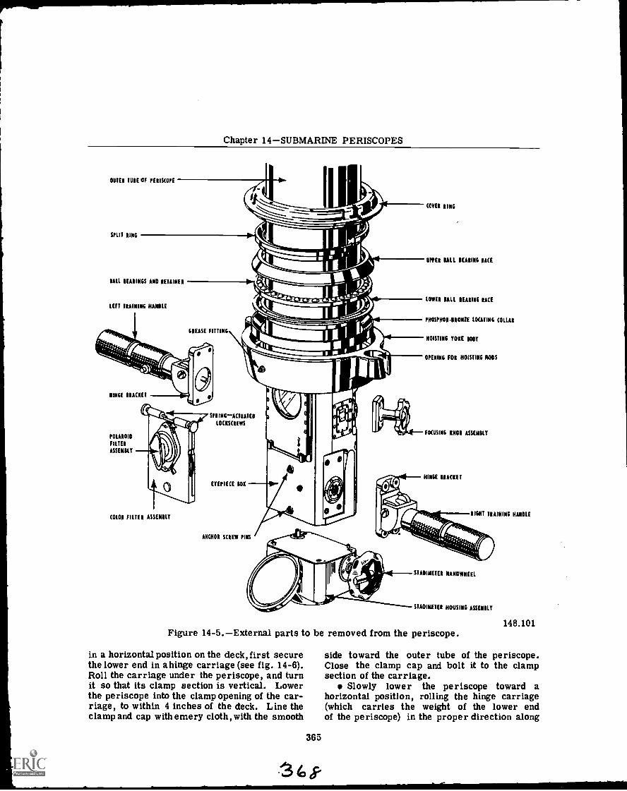
Chapter 14SUBMARINE PERISCOPES
OUTER TUBE OF PERISCOPE
SPLIT RING
BALL BEARINGS AND RETAINER
LEFT TRAINING HANDLE
GREASE FITTING
HINGE BRACKET
POLAROID
FILTER
ASSEMBLY
COLOR FILTER ASSEMBLY
SPRING-ACTUATED
LOCKSCREWS
EYEPIECE BOX
ANCHOR SCREW PINS
COVER RING
UPPER BALL BEARING RACE
LOWER BALL BEARING RACE
PHOSPHORBRONZE LOCATING COLLAR
HOISTING YOKE BODY
OPENING FOR HOISTING RODS
FOCUSING KNOB ASSEMBLY
HINGE BRACKET
RIGHT TRAINING HANDLE
STADIMETER HANDWHEEL
STADIMETER HOUSING ASSEMBLY
Figure 14-5.External parts to be removed from the periscope.
in a horizontal position on the deck, first securethe lower end in ahinge carriage (see fig. 14-6).Roll the carriage under the periscope, and turnit so that its clamp section is vertical. Lowerthe periscope into the clamp opening of the car-riage, to within 4 inches of the deck. Line theclamp and cap with emery cloth, with the smooth
365
148.101
side toward the outer tube of the periscope.Close the clamp cap and bolt it to the clampsection of the carriage.
Slowly lower the periscope toward ahorizontal position, rolling the hinge carriage(which carries the weight of the lower endof the periscope) in the proper direction along
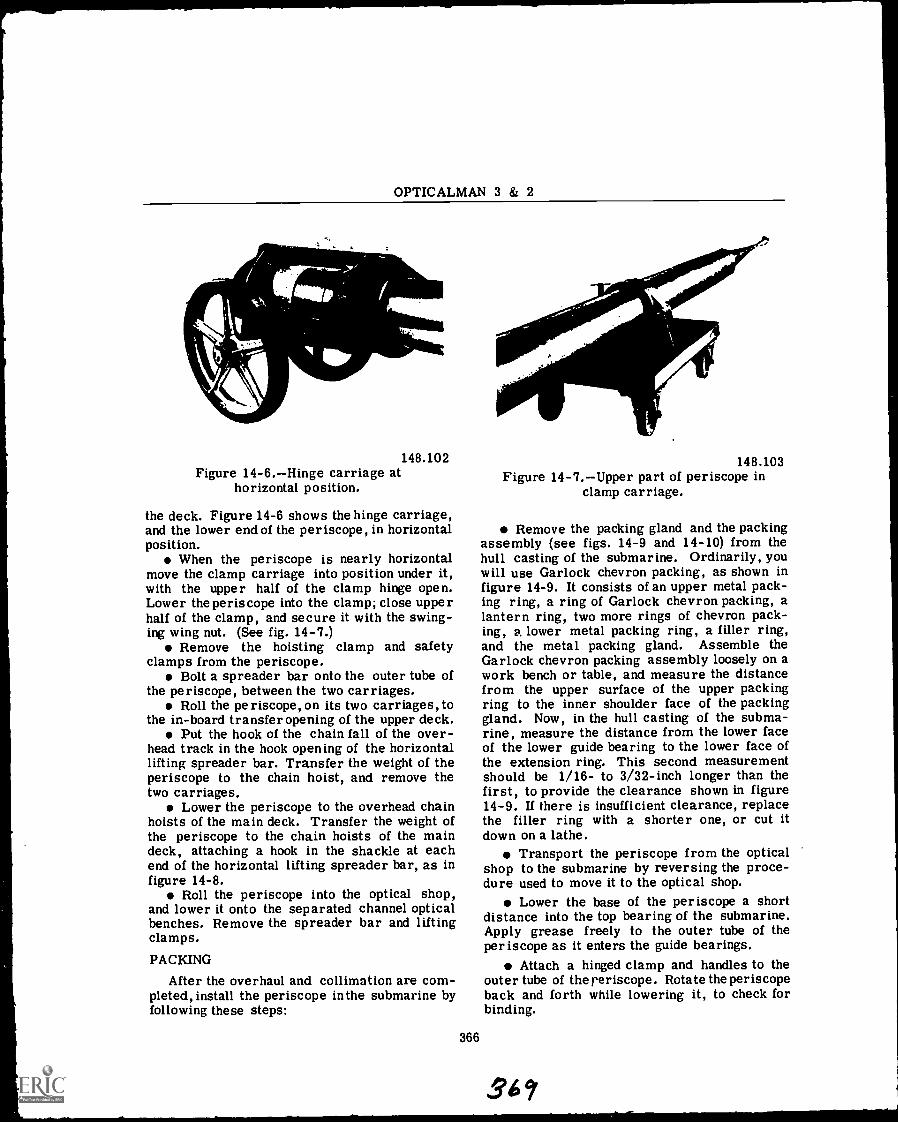
/11116.24___
OPTICALMAN 3 & 2
148.102Figure 14-6.Hinge carriage at
horizontal position.
the deck. Figure 14-6 shows the hinge carriage,and the lower end of the periscope, in horizontalposition.
When the periscope is nearly horizontalmove the clamp carriage into position under it,with the upper half of the clamp hinge open.Lower the periscope into the clamp; close upperhalf of the clamp, and secure it with the swing-ing wing nut. (See fig. 14-7.)
Remove the hoisting clamp and safetyclamps from the periscope.
Bolt a spreader bar onto the outer tube ofthe periscope, between the two carriages.
Roll the periscope, on its two carriages, tothe in-board transfer opening of the upper deck.
Put the hook of the chain fall of the over-head track in the hook opening of the horizontallifting spreader bar. Transfer the weight of theperiscope to the chain hoist, and remove thetwo carriages.
Lower the periscope to the overhead chainhoists of the main deck. Transfer the weight ofthe periscope to the chain hoists of the maindeck, attaching a hook in the shackle at eachend of the horizontal lifting spreader bar, as infigure 14-8.
Roll the periscope into the optical shop,and lower it onto the separated channel opticalbenches. Remove the spreader bar and liftingclamps.
PACKING
After the overhaul and collimation are com-pleted, install the periscope in the submarine byfollowing these steps:
366
148.103Figure 14-7.Upper part of periscope in
clamp carriage.
Remove the packing gland and the packingassembly (see figs. 14-9 and 14-10) from thehull casting of the submarine. Ordinarily, youwill use Garlock chevron packing, as shown infigure 14-9. It consists of an upper metal pack-ing ring, a ring of Garlock chevron packing, alantern ring, two more rings of chevron pack-ing, a lower metal packing ring, a filler ring,and the metal packing gland. Assemble theGarlock chevron packing assembly loosely on awork bench or table, and measure the distancefrom the upper surface of the upper packingring to the inner shoulder face of the packinggland. Now, in the hull casting of the subma-rine, measure the distance from the lower faceof the lower guide bearing to the lower face ofthe extension ring. This second measurementshould be 1/16- to 3/32-inch longer than thefirst, to provide the clearance shown in figure14-9. If there is insufficient clearance, replacethe filler ring with a shorter one, or cut itdown on a lathe.
Transport the periscope from the opticalshop to the submarine by reversing the proce-dure used to move it to the optical shop.
Lower the base of the periscope a shortdistance into the top bearing of the submarine.Apply grease freely to the outer tube of theperiscope as it enters the guide bearings.
Attach a hinged clamp and handles to theouter tube of the reriscope . Rotate the periscopeback and forth while lowering it, to check forbinding.
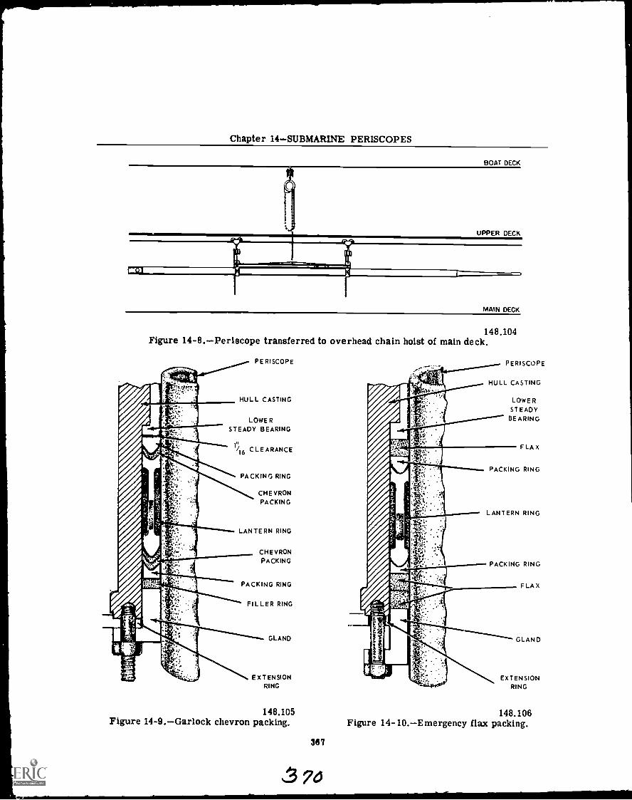
Chapter 14SUBMARINE PERISCOPES
MAIN DECK
148.104Figure 14-8.Periscope transferred to overhead chain hoist of main deck.
PERISCOPE
HULL CASTING
LOWERSTEADY BEARING
CLEARANCE
PACKING RING
CHEVRONPACKING
LANTERN RING
CHEVRONPACKING
PACKING RING
FILLER RING
GLAND
EXTENSIONRING
148.105Figure 14-9.Garlock chevron packing.
367
74
HULL CASTING
LOWERSTEADY
BEARING
FLAX
PACKING RING
LANTERN RING
PACKING RING
FLAX
EXTENSIONRING
148.106Figure 14-10.Emergency flax packing.
OPTICALMAN 3 & 2
When the periscope has been lowered tothe observing position, replace the hull packingassembly. In reassembly pack the cavity aroundthe lantern ring with grease and bring the pack-ing gland hard against its shoulder. Now with a0.006-inch feeler gage, check the clearance be-tween the outer tube of the periscope and theinner circumference of the packing gland. Theclearance should be uniform all the way around.
After the packing is placed in the hull glandassemble the azimuth circle and auxiliarycircle attachment to the extension ring. Trainthe periscope on the forward and after benchmarks of the submarine, to be sure the azimuthcircle reads correctly on the lubber's line.
Reassemble the hoisting yoke, and fill itwith mineral grease, Grade II medium.
Now, while raising and lowering the peri-scope, fill the lantern ring cavity, through theexternal grease fitting of the hull casting, withmineral grease, Grade II medium.
Assemble all the external parts of the eye-piece box, following the disassembly steps inreverse.
Train the periscope several times through360°, and watch the azimuth circle. If the peri-scope grinds against it, the circle has been im-properly mounted. Remount it in the properposition. While training the periscope, listenfor grinding in the guide bearings. If you heargrinding, it probably means that chips of metalhave fallen into the bearings during assembly.To correct this, the periscope must be with-drawn, the outer tube scratches smoothed down,and the guide bearings cleaned and repacked.
Check the periscope training handles, thealtiscope, and the power shift, to be sure theyare all functioning properly. Check the sta-dimeter in the observing position, to be surethere is no double image at the infinity read-ing. Check the focusing adjustment; the rangeof diopter setting should be from -3 to +1 1/2diopters.
When the periscope is in satisfactory con-dition, report to the submarine officer and askhim to inspect it for approval.
At this point we will discuss packing leakage.When leakage occurs through the Garlock pack-ing, you will be expected to fix it. The usualcause of leakage through the chevron packing isdistortion of the packing ring, which opens up acrack between the packing and the periscope.Usually the leakage can be stopped by removingthe packing and replacing it. Should leakagecontinue after the hull gland has been packed
according to specifications, use the followingcheck list to locate the problem area.
Support bearing and hull gland alignment.Eccentricity in packing gland.Eccentricity in lantern or packing ring.Proper size of hull gland.Concentricity and size of periscope outertube.
When necessary an emergency flax packingcan be used when assembled as shown in figure14-10. This will stop the leak, but has the dis-advantage of making the periscope harder totrain. Cut the flax packing rings with squareends, and measure them to fit the inner cir-cumference of the hull casting, rather than theouter circumference of the periscope. As youbring up the packing gland, be sure to checkfor uniform clearance with a feeler gage. Thisis especially important with flax packing, sincethe gland is not brought all the way up againstthe extension ring.
STORAGE
A modern submarine periscope, in spite ofits size (up to 50 feet in length) and weight (upto 2,000 pounds) is a fragile instrument. Whenmoving it from one place to another, be con-stantly alert to protect it from bending, vibra-tion, or shock. Periscopes are shipped andstored in sturdy boxes, and are secured byclamps. These clamps prevent endwise move-ment within the box.
When you remove a periscope from its box,be sure to put the clamps back in the box sothey can be used again. When returning a peri-scope to its box for reshipment, be sure that allthe clamps are in place. See that all accesso-ries are either mounted on the periscope itself,or carefully secured inside the box.
When moving a periscope in its box, alwayshoist or support the box at more than one pointpreferably at the quarter pointsto preventneedless stresses on the periscope tube. If aperiscope is shipped by rail, the box should besecurely chocked in the car. For highway ship-ping a reach truck should be used if available.The box should be so loaded on the truck thatthe overhanging end contains the upper, lighterend of the periscope. The nameplate of theshipping box should always be at the heavy end.
EXTERNAL MAINTENANCE
The following pages of this chapter will de-scribe some of the maintenance procedures you
368
3 1/
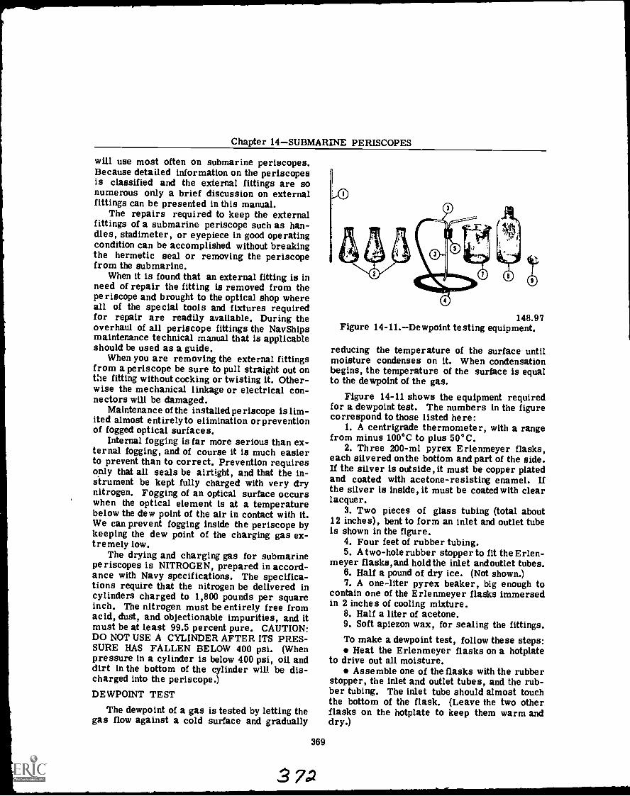
Chapter 14SUBMARINE PERISCOPES
will use most often on submarine periscopes.Because detailed information on the periscopesis classified and the external fittings are sonumerous only a brief discussion on externalfittings can be presented in this manual.
The repairs required to keep the externalfittings of a submarine periscope such as han-dles, stadimeter, or eyepiece in good operatingcondition can be accomplished without breakingthe hermetic seal or removing the periscopefrom the submarine.
When it is found that an external fitting is inneed of repair the fitting is removed from theperiscope and brought to the optical shop whereall of the special tools and fixtures requiredfor repair are readily available. During theoverhaul of all periscope fittings the Nav Shipsmaintenance technical manual that is applicableshould be used as a guide.
When you are removing the external fittingsfrom a periscope be sure to pull straight out onthe fitting without cocking or twisting it. Other-wise the mechanical linkage or electrical con-nectors will be damaged.
Maintenance of the installed periscope is lim-ited almost entirelyto elimination orpreventionof fogged optical surfaces.
Internal fogging is far more serious than ex-ternal fogging, and of course it is much easierto prevent than to correct. Prevention requiresonly that all seals be airtight, and that the in-strument be kept fully charged with very drynitrogen. Fogging of an optical surface occurswhen the optical element is at a temperaturebelow the dew point of the air in contact with it.We can prevent fogging inside the periscope bykeeping the dew point of the charging gas ex-tremely low.
The drying and charging gas for submarineperiscopes is NITROGEN, prepared in accord-ance with Navy specifications. The specifica-tions require that the nitrogen be delivered incylinders charged to 1,800 pounds per squareinch. The nitrogen must be entirely free fromacid, dust, and objectionable impurities, and itmust be at least 99.5 percent pure. CAUTION:DO NOT USE A CYLINDER AFTER ITS PRES-SURE HAS FALLEN BELOW 400 psi. (Whenpressure in a cylinder is below 400 psi, oil anddirt in the bottom of the cylinder will be dis-charged into the periscope.)DEWPOINT TEST
The dewpoint of a gas is tested by letting thegas flow against a cold surface and gradually
369
3 7 .2
148.97Figure 14-11.Dewpoint testing equipment.
reducing the temperature of the surface untilmoisture condenses on it. When condensationbegins, the temperature of the surface is equalto the dewpoint of the gas.
Figure 14-11 shows the equipment requiredfor a dewpoint test. The numbers in the figurecorrespond to those listed here:
1. A centrigrade thermometer, with a rangefrom minus 100°C to plus 50°C.
2. Three 200-m1 pyrex Erlenmeyer flasks,each silvered onthe bottom and part of the side.If the silver is outside, it must be copper platedand coated with acetone-resisting enamel. Ifthe silver is inside, it must be coated with clearlacquer.
3. Two pieces of glass tubing (total about12 inches), bent to form an inlet and outlet tubeis shown in the figure.
4. Four feet of rubber tubing.5. A two-hole rubber stopper to fit the Erlen-
meyer flasks,and hold the inlet andoutlet tubes.6. Half a pound of dry ice. (Not shown.)7. A one-liter pyrex beaker, big enough to
contain one of the Erlenmeyer flasks immersedin 2 inches of cooling mixture.
8. Half a liter of acetone.9. Soft apiezon wax, for sealing the fittings.To make a dewpoint test, follow these steps:
Heat the Erlenmeyer flasks on a hotplateto drive out all moisture.
Assemble one of the flasks with the rubberstopper, the inlet and outlet tubes, and the rub-ber tubing. The inlet tube should almost touchthe bottom of the flask. (Leave the two otherflasks on the hotplate to keep them warm anddry.)
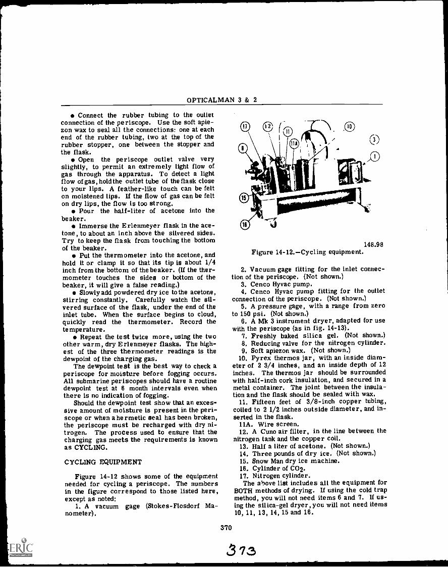
OPTICALMAN 3 & 2
Connect the rubber tubing to the outletconnection of the periscope. Use the soft apie-zon wax to seal all the connections: one at eachend of the rubber tubing, two at the top of therubber stopper, one between the stopper andthe flask.
Open the periscope outlet valve veryslightly, to permit an extremely light flow ofgas through the apparatus. To detect a lightflow of gas, hold the outlet tube of the flask closeto your lips. A feather-like touch can be felton moistened lips. If the flow of gas can be felton dry lips, the flow is too strong.
Pour the half-liter of acetone into thebeaker.
Immerse the Erlenmeyer flask in the ace-tone, to about an inch above the silvered sides.Try to keep the flask from touching the bottomof the beaker.
Put the thermometer into the acetone, andhold it or clamp it so that its tip is about 1/4inch from the bottom of the beaker. (If the ther-mometer touches the sides or bottom of thebeaker, it will give a false reading.)
Slowly add powdered dry ice to the acetone,stirring constantly. Carefully watch the sil-vered surface of the flask, under the end of theinlet tube. When the surface begins to cloud,quickly read the thermometer. Record thetemperature.
Repeat the test twice more, using the twoother warm, dry Erlenmeyer flasks. The high-est of the three thermometer readings is thedewpoint of the charging gas.
The dewpoint test is the best way to check aperiscope for moisture before fogging occurs.All submarine periscopes should have a routinedewpoint test at 6 month intervals even whenthere is no indication of fogging.
Should the dewpoint test show that an exces-sive amount of moisture is present in the peri-scope or when a hermetic seal has been broken,the periscope must be recharged with dry ni-trogen. The process used to ensure that thecharging gas meets the requirements is knownas CYCLING.
CYCLING EQUIPMENT
Figure 14-12 shows some of the equipmentneeded for cycling a periscope. The numbersin the figure correspond to those listed here,except as noted:
1. A vacuum gage (Stokes-Flcsdorf Ma-nometer).
148.98Figure 14-12.Cycling equipment.
2. Vacuum gage fitting for the inlet connec-tion of the periscope. (Not shown.)
3. Cenco Hyvac pump.4. Cenco Hyvac pump fitting for the outlet
connection of the periscope. (Not shown.)5. A pressure gage, with a range from zero
to 150 psi. (Not shown.)6. A Mk 3 instrument dryer, adapted for use
with the periscope (as in fig. 14-13).7. Freshly baked silica gel. (Not shown.)8. Reducing valve for the nitrogen cylinder.9. Soft apiezon wax. (Not shown.)
10. Pyrex thermos jar, with an inside diam-eter of 2 3/4 inches, and an inside depth of 12inches. The thermos jar should be surroundedwith half-inch cork insulation, and secured in ametal container. The joint between the insula-tion and the flask should be sealed with wax.
11. Fifteen feet of 3/8-inch copper tubing,coiled to 2 1/2 inches outside diameter, and in-serted in the flask.
11A. Wire screen.12. A Cuno air filter, in the line between the
nitrogen tank and the copper coil.13. Half a liter of acetone. (Not shown.)14. Three pounds of dry ice. (Not shown.)15. Snow Man dry ice machine.16. Cylinder of CO2.17. Nitrogen cylinder.The above list includes all the equipment for
BOTH methods of drying. If using the cold trapmethod, you will not need items 6 and 7. If us-ing the silica-gel dryer, you will not need items10, 11, 13, 14, 15 and 16.
370
313
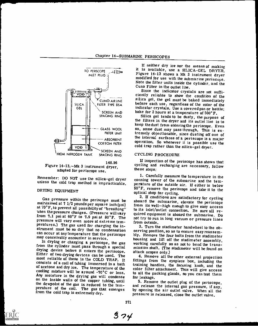
Chapter 14SUBMARINE PERISCOPES
TO PERISCOPE __Ltrir/xoINLET PLUG
----CUNO AIR LINE
\ FILTER TYPE DSA
SCREEN ANDSPACING RING
GLASS WOOLFILTER UNIT
ABSORBENTCOTTON FILTER
FROM NITROGEN TANKSCREEN AND
SPACING RING
148.96Figure 14-13.--Mk 3 instrument dryer,
adapted for periscope use.
Remember: DO NOT use the silica-gel dryerunless the cold trap method is impracticable.
DRYING EQUIPMENT
Gas pressure within the periscope must bemaintained at 7 1/2 pounds per square inch (psi)at 70°F, to prevent all possibilityof "breathing"when the pressure changes. (Pressure will varyfrom 7.1 psi at 60°F to 7.9 psi at 80°F. Thepressure will vary even more at extreme tem-peratures.) The gas used for charging the in-strument must be so dry that no condensationcan occur at any temperature that the periscopemay conceivably encounter in service.
In drying or charging a periscope, the gasfrom the cylinder must pass through a specialdrying device before it enters the periscope.Either of two drying devices can be used. Themost reliable of these is the COLD TRAP. Itconsists of a coil of tubing immersed in a bathof acetone and dry ice. The temperature of thecooling mixture will be around -70°C or less.Any moisture in the drying gas will condenseon the inside walls of the copper tubing, untilthe dewpoint of the gas is reduced to the tem-perature of the coil. The gas that emergesfrom the cold trap is extremely dry.
371
If neither dry ice nor the means of makingit is available, use a SILICA-GEL DRYER.Figure 14-13 shows a Mk 3 instrument dryermodified for use with the submarine periscope.Note the filter units inside the cylinder, and theCuno Filter in the outlet line.
Since the indicator crystals are not suffi-ciently reliable to show the condition of thesilica gel, the gel must be baked immediatelybefore each use, regardless of the color of theindicator crystals. Use a covered pan or kettle;bake for 2 hours at a temperature of 500°F.
Silica gel tends to be dusty, the purpose ofthe filters in the dryer and its outlet line is tokeep thedust from enteringthe periscope. Evenso, some dust may pass through. This is ex-tremely objectionable, since dusting off one ofthe internal surfaces of a periscope is a majoroperation. So whenever it is possible use thecold trap rather than the silica-gel dryer.
CYCLING PROCEDURE
If inspection of the periscope has shown thatcycling and recharging are necessary, followthese steps:
1. Carefully measure the temperature in theconning tower of the submarine and the tem-perature of the outside air. If either is below50°F, remove the periscope and take it to theoptical shop for cycling.
2. If conditions are satisfactory for cyclingaboard the submarine, elevate the periscopefrom its wellhigh enough to give easy accessto its inlet/outlet connection. Be sure all re-quired equipment is aboard the submarine. Donot try to run in long vacuum or pressure linesfrom outside.
3. Turn the stadimeter handwheel to the ob-serving position, so as to ensure easy reassem-bly. Remove the four bolts from the stadimeterhousing and lift off the stadimeter assembly,working carefully so as not to bend the trans-mission shaft. (The stadimeter will be found onattack scopes only.)
4. Remove all the other external projectionfittings from the eyepiece box, including thetraining handles, the focusing knob, and thecolor filter attachment. This will give accessto all the packing glands, so you can test themfor leakage.
5. Remove the outlet plug of the periscope,and release the internal gas pressure, if any,by opening the air outlet valve. When all thepressure is released, close the outlet valve.
OPTICALMAN 3 & 2
6. Remove the inlet plug, and secure the hosefitting in the inlet connection.
7. Insert the zero to 150 psi gage in the airoutlet fitting and use an offset screwdriver toopen the outlet valve, as in figure 14-13.
8. Connect the nitrogen cylinder, through thereducing valve and the dryer, to the inlet con-nection of the periscope. If you are using thecold trap dryer, pour half a liter of acetone intothe flask, and stir 3 pounds of powdered dry iceinto the acetone. Run gas slowly through thedryer and charging lines for about a minute be-fore making the connection to the periscope.
9. Close the reducing valve on the nitrogencylinder. Open the main valve, and set the re-ducing valve for a pressure of 10 psi. Thenopen the inlet valve of the periscope.
10. Slowly build up the pressure. Rememberthat strong gas currents in the periscope maydeposit dust on the optical surfaces, and a sud-den increase in pressure may throw the opticalsystem out of line. Raise the pressure in 4-pound steps, holding each value for about 5minutes before increasing it. The pressureshould build up to 100 psi (50 psi for scopessealed with "0" rings) in about 2 hours.
11. When the gage in the outlet connectionshows a pressure of 100 psi, close the inletvalve of the periscope. Close off the nitrogenpressure at the cylinder, and remove thecharging line fitting from the periscope inletconnection.
12. Now check the periscope for leaks. Ifpossible submerge the entire lower end, in-cluding the whole eyepiece box, in a containerof water. If that is not possible, coat all con-nections and packing glands with heavy soap-suds, and watch for bubbles. At the periscopehead, soap the edge of the window, the bezelframe screwheads, the gasket, the connectionbetween the head and the taper section, and thebolts that secure that connection. If there isany sign of leakage, eliminate the leak beforedrawing a vacuum. A leak through a packinggland can sometimes be stopped by tighteningthe gland. If necessary, release the gas pres-sure (slowly, over a period of 2 hours), replacethe faulty packing or gasket, and repeat thepressure test.
13. When you are satisfied that the periscopeis gastight, close the air outlet valve andremove the pressure gage from the outletconnection.
14. Open the outlet valve slightly, to releasethe pressure slowly and gradually over a period
of 2 hours. When all pressure has been re-leased, close the outlet valve.
15. Connect the mercury manometer fittingto the inlet connection.
16. Connect the evacuating fitting to the airoutlet connection. Keep all leads short, withas few joints as possible, to reduce the possi-bility of leakage.
17. Start the Cenco Hyvac pump, and thenopen the outlet valve. Do not leave the pumpunattended while it is drawing the vacuum. Ifthe pump should stop, or show signs of stop-ping, quickly grab the hose, kink it, and closethe air outlet valve to prevent the periscopevacuum from drawing air back through thepump. The air that is drawn back will carryoil and oil vapor from the pump into the peri-scope and deposit it on the optical surfaces. Ittakes a major overhaul to repair this damage.
18. When the pump is operating properly openthe inlet valve, so the manometer can indicatethe vacuum in the periscope. Keep pumpinguntil the manometer shows a pressure of 4 mmor less (2 mm, if it is possible to pump it downthat low). Then close the outlet valve, andsecure the pump.
19. Hold the vacuum for 3 hours, and thenread the manometer. Any rise in pressureshows that drying is incomplete, and so willrequire more pumping.
NOTE: if you continue pumping, start thepump and let it run a few seconds BEFOREopening the outlet valve.
20. When the periscope will hold a vacuum,close both the inlet and outlet valves, and dis-connect the pump and manometer.
21. Now the periscope is ready for charging.Run nitrogen through the dryer and connectinglines for a few seconds, then connect the line tothe input fitting of the periscope. If a cold trapdryer is being used, add more dry ice to theacetone, to bring the mixture up to the top ofthe coil.
22. Insert the pressure gage in the air outletconnection, and open the outlet valve.
23. Slowly open the inlet valve, and graduallybuild up the pressure to 10 psi. Then close theinlet valve, and shut off the nitrogen pressureat the cylinder. Disconnect the nitrogen inletfitting, and replace the inlet plug.
24. Close the outlet valve, and remove thepressure gage. Connect the dewpoint test ap-paratus to the outlet fitting, and a dewpointtest. If the dewpoint is higher than minus 50°C,
372
37S
Chapter 14SUBMARINE PERISCOPES
you must repeat the cycling procedure from thebeginning.
25. If the dewpoint is satisfactory, bleed thepressure VERY SLOWLY, through the outletvalve, to 7 1/2 psi. If the periscope has abuilt-in gage, this is easy. If it does nothave a built-in gage, bleed a small amount ofgas, close the outlet valve, insert the gage
373
37,6
in the outlet connection, open the valve, andread the gage. Then close the valve, removethe gage, and continue bleeding, with frequentpressure checks, to 7 1/2 psi.
26. The cycling procedure is now complete.Secure all the cycling equipment. Replace theoutlet plug, and all the external fittings ofthe periscope.
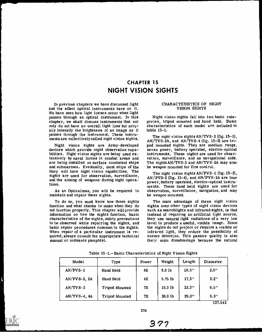
CHAPTER 15
NIGHT VISION SIGHTS
In previous chapters we have discussed lightand the effect optical instruments have on it.We have seen how light losses occur when lightpasses through an optical instrument. In thischapter, we shall discuss instruments that notonly do not have an overall light loss but actu-ally intensify the brightness of an image as itpasses through the instrument. These instru-ments are collectively called night vision sights.
Night vision sights are Army-developeddevices which provide night observation capa-bilities. Night vision sights are being used ex-tensively by naval forces in combat areas andare being installed on surface combatant shipsand submarines. Eventually, most ships of theNavy will have night vision capabilities. Thesights are used for observation, surveillance,and the aiming of weapons during night opera-tions.
As an Opticalman, you will be required tomaintain and repair these sights.
To do so, you must know how these sightsfunction and what checks to make when they donot function properly. This chapter will provideinformation on how the sights function, basiccharacteristics of the sights, safety precautionsto be observed while repairing the sights, andbasic repair procedures common to the sights.When repair of a particular instrument is re-quired, always consult the appropriate technicalmanual or ordnance pamphlet.
CHARACTERISTICS OF NIGHTVISION SIGHTS
Night vision sights fall into two basic cate-gories, tripod mounted and hand held. Basiccharacteristics of each model are included intable 15-1.
The night vision sights AN/TVS-2 (fig. 15-1),AN/TVS-2A, and AN/TVS-4 (fig. 15-2) are tri-pod mounted sights. They are medium range,seven power, battery operated, electro-opticalinstruments. These sights are used for obser-vation, surveillance, and as navigational aids.The sights AN/TVS-2 and AN/TVS-2A may alsobe weapon mounted for fire control.
The night vision sights AN/PVS-1 (fig. 15-3),AN/PVS-2 (fig. 15-4), and AN/PVS-2A are fourpower, battery operated, electro-optical instru-ments. These hand held sights are used forobservation, surveillance, navigation, and maybe weapon mounted.
The main advantage of these night visionsights over other types of night vision devicessuch as searchlights and infrared sights, is thatinstead of requiring an artificial light source,they use natural light radiations of a very lowlevel to produce a useful, visible image. Sincethe sights do not project or require a visible orinfrared light, they reduce the possibility ofenemy detection. This passive quality is alsotheir main disadvantage because the natural
Table 15-1.Basic Characteristics of Night Vision Sights
Model Type Power Weight Length Diameter
AN/PVS-1 Hand Held 4X 6.0 lb 18.5" 3.5"
AN/PVS-2, 2A Hand Held 4X 5.75 lb 17.5" 3.2"
AN/TVS-2 Tripod Mounted 7X 15.0 lb 23.5" 6.5"
AN/TVS-4, 4A Tripod Mounted 7X 38.0 lb 29.0" 8.3"
374
a 7?
137.542
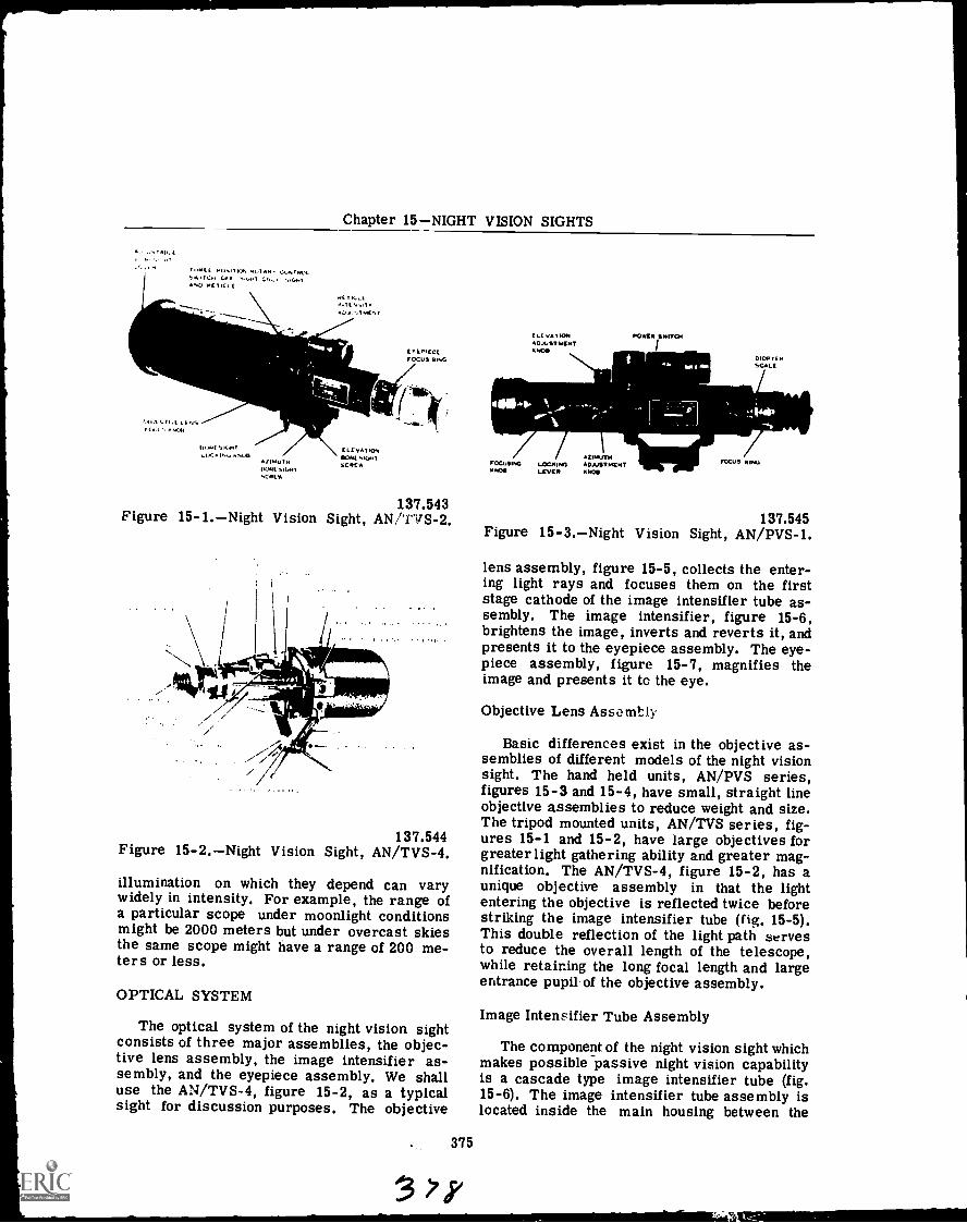
Chapter 15NIGHT VISION SIGHTS
T "PE I. POs T RoT AM. 03NT ROILe'..i ,UnT
AND NCTICklE
Hl T ICLLTEN,TY
ALAN TOAC.%7
EYEPIECEFOCUS RING
IN1NE SILJITLl/Cr KM1CA
AfIMUTHDoNCsiONT,CREN
ELL VAT IONSONE SIGNTSERER
137.543Figure 15-1.Night Vision Sight, AN/TVS-2.
137.544Figure 15-2.Night Vision Sight, AN/TVS-4.
illumination on which they depend can varywidely in intensity. For example, the range ofa particular scope under moonlight conditionsmight be 2000 meters but under overcast skiesthe same scope might have a range of 200 me-ters or less.
OPTICAL SYSTEM
The optical system of the night vision sightconsists of three major assemblies, the objec-tive lens assembly, the image intensifier as-sembly, and the eyepiece assembly. We shalluse the AN/TVS-4, figure 15-2, as a typicalsight for discussion purposes. The objective
375
it
ELEVATIONADJUSTMENTANDS
POOLS MITCH
DIOPTCMSCALE
FOCUSINGANDS
LOCH INGLEVER
AZIMUTHADJUSTMENTENOS
FOCUS RING
137.545Figure 15-3.Night Vision Sight, AN/PVS-1.
lens assembly, figure 15-5, collects the enter-ing light rays and focuses them on the firststage cathode of the image intensifier tube as-sembly. The image intensifier, figure 15-6,brightens the image, inverts and reverts it, andpresents it to the eyepiece assembly. The eye-piece assembly, figure 15-7, magnifies theimage and presents it to the eye.
Objective Lens Assembly
Basic differences exist in the objective as-semblies of different models of the night visionsight. The hand held units, AN/PVS series,figures 15-3 and 15-4, have small, straight lineobjective assemblies to reduce weight and size.The tripod mounted units, AN/TVS series, figures 15-1 and 15-2, have large objectives forgreater light gathering ability and greater ma -nification. The AN/TVS-4, figure 15-2, has aunique objective assembly in that the lightentering the objective is reflected twice beforestriking the image intensifier tube (fig. 15-5).This double reflection of the light path servesto reduce the overall length of the telescope,while retaining the long focal length and largeentrance pupil of the objective assembly.
Image Intensifier Tube Assembly
The component of the night vision sight whichmakes possible passive night vision capabilityis a cascade type image intensifier tube (fig.15-6). The image intensifier tube assembly islocated inside the main housing between the
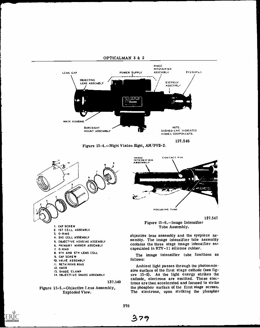
OPTICALMAN 3 & 2
LENS CAP
\ OBJECTIVELENS ASSEMBLY
MAIN HOUSING
M611
II
BORESIGHTMOUNT ASSEMBLY
POWER SLUPPLY
_.1.._
IMAGEINTENSIFIERASSEMBLY
i
/ EYEPIECEASSEMBLE'
I
EY ESHIF Li)
NOTEOASHEO LINE I NOICATESHIOOEN COMPONENTS.
Figure 15-4.Night Vision Sight, AN/PVS-2.
I. CAP SCREW2. 1ST CELL ASSEMBLY3. 0-RING4. 2ND CELL ASSEMBLY5. OBJECTIVE HOUSING ASSEMBLY6. PRIMARY MIRROR ASSEMBLY7. 0-RING8. 4TH AND 5TH LENS CELL9. CAP SCREW10. VALVE ASSEMBLYII. RETAINING RING12. KNOB13. SHADE CLAMP14. OBJECTIVE SHADE ASSEMBLY
137.549
Figure 15-5.Objective Lens Assembly,Exploded View.
376
IMAGEINTENSIFIERASSEMBLY
137.546
CONTACT PIN
FOCUSING TUBE
137.547Figure 15-6.Image Intensifier
Tube Assembly.
objective lens assembly and the eyepiece as-sembly. The image intensifier tube assemblycontains the three stage image intensifier en-capsulated in RTV-11 silicone rubber.
The image intensifier tube functions asfollows:
Ambient light passes through the photoemis-sive surface of the first stage cathode (see fig-ure 15-8). As the light energy strikes thecathode, electrons are emitted. These elec-trons are then accelerated and focused to strikethe phosphor surface of the first stage screen.The electrons, upon striking the phosphor
.571

Chapter 15NIGHT VISION SIGHTS
EYEPIECEASSEMBLY
RANGEFOCUSRING
.N11111..
FOCUSINGTUBE \
Ir
STEP I. UNTHREAD EYEPIECE ASSEMBLY FROM FOCUS-ING TUBE IN COUNTER-CLOCKWISE DIRECTION.
STEP 2. UNTHREAD RANGE FOCUS RING FROM FOCUS-ING TUBE IN COUNTER-CLOCKWISE DIRECTION.
LIGHTOUT
137.550Figure 15-7.Removal of EyepieceAssembly and Range Focus Ring.
3.0 STAGE 2nd STAGECATHODE CATHODE
STAGE
CATHODE
LIGHTIN
SCREEN SCREEN SCREEN
NOTE: 45,000 VDC POTENTIAL EXISTS BETWEEN THE CATHODEAND SCREEN OF EACH STAGE.
137.548Figure 15-8.Image Intensifier Tube,
Functional Diagram.
screen, are re-radiated as visible light but, thetotal amount of light has been greatly increasedduring the process. This process continuesthrough two successive stages until the lightlevel becomes great enough to be seen by theobserver through the eyepiece. The overalllight gain provided by the three intensificationstages results in an image, presented to theeye, which is approximately 50,000 timesbrighter than the image entering the objectivelens.
SAFETY PRECAUTIONS
Prior to performing any maintenance o.repair to any of the night vision sights, a fewsimple but absolutely necessary safety precau-tions must be learned and observed. Shouldyou violate any of these safety precautions, itis very possible you will suffer physical damage.
The image intensifier tube will normallyhave a residual high voltage charge of approxi-mately 45,000 volts d-c. This charge must beremoved to eliminate the hazard of electricalshock when the image intensifier tube is re-moved from its housing.
The phosphor screens, figure 15-8, of theimage intensifier tube contain toxic material.If the image intensifier tube should be broken,use extreme caution to avoid inhalation of thephosphor material and to prevent it from com-ing into contact with the mouth or any openskin wound.
The eyepiece assembly and the objectiveassembly will normally have an internal pres-sure of 5 pounds of nitrogen. This pressuremust be released prior to disassembly shouldthat become necessary.
Finally, to avoid damaging the night visionsight, do not energize the sight in a lightedarea. As the image intensifier tube is ex-tremely sensitive to light, tube damage willresult if the sight is energized in too bright anarea.
377
PREMAINTENANCE INSPECTIONS
When a night vision sight is submitted forrepair, certain premaintenance inspectionsmust be performed in order to determine theextent of repairs necessary. These checksconsist of mechanical and optical inspections c4.the sight to determine their physical condition,along with electrical inspections to determinethe condition of the electrical system.
OPTICAL AND MECHANICAL
Visually check all external surfaces to de-termine if there are any obviously damagedcomponents that require repair or replacement.Operate the eyepiece assembly and the rangefocus assembly to determine that they rotatesmoothly without binding. In order to make thenecessary optical checks, be sure the objectivecover is in place. Observing the proper pro-cedures set forth in the operators manual,
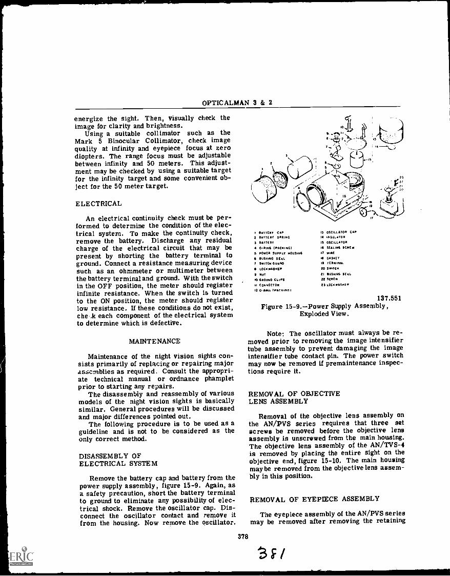
OPTICALMAN 3 & 2
energize the sight. Then, visually check theimage for clarity and brightness.
Using a suitable collimator such as theMark 5 Binocular Collimator, check imagequality at infinity and eyepiece focus at zerodiopters. The range focus must be adjustablebetween infinity and 50 meters. This adjust-ment may be checked by using a suitable targetfor the infinity target and some convenient ob-ject for the 50 meter target.
ELECTRICAL
An electrical continuity check must be per-formed to determine the condition of the elec-trical system. To make the continuity check,remove the battery. Discharge any residualcharge of the electrical circuit that may bepresent by shorting the battery terminal toground. Connect a resistance measuring devicesuch as an ohmmeter or multimeter betweenthe battery terminal and ground. With the switchin the OFF position, the meter should registerinfinite resistance. When the switch is turnedto the ON position, the meter should registerlow resistance. If these conditions do not exist,the .k each component of the electrical systemto determine which is defective.
MAINTENANCE
Maintenance of the night vision sights con-sists primarily of replacing or repairing majorassemblies as required. Consult the appropri-ate technical manual or ordnance phampletprior to starting any repairs.
The disassembly and reassembly of variousmodels of the night vision sights is basicallysimilar. General procedures will be discussedand major differences pointed out.
The following procedure is to be used as aguideline and is not to be considered as theonly correct method.
DISASSEMBLY OFELECTRICAL SYSTEM
Remove the battery cap and battery from thepower supply assembly, figure 15-9. Again, asa safety precaution, short the battery terminalto ground to eliminate any possibility of elec-trical shock. Remove the oscillator cap. Dis-connect the oscillator contact and remove itfrom the housing. Now remove the oscillator.
378
I BATTERY EAR 15 °UNA TOR CAP2 BATTERY SPRING 14 INSULATOR
S BATTERY 15 OSCILLATOR
4 0-RING (PAO( NG) 16 SEALING SCREW
5 POWER SUPPLY HOUSING 1? WIRE
6 RUSHING SEAL 19 GASNET
7 SWITCH GUARD 19 TERMINAL
LOCNWA$HER 20 SWITCH
9 NUT EI BUSHING SEAL
'0 GROUND CLIPS 22 SCREW
11 CONNECTOR 25 LOCH WASHER
a O.ReNn IPACRINNI
137.551Figure 15-9.Power Supply Assembly,
Exploded View.
Note: The oscillator must always be re-moved prior to removing the image intensifiertube assembly to prevent damaging the imageintensifier tube contact pin. The power switchmay now be removed if premaintenance inspec-tions require it.
REMOVAL OF OBJECTIVELENS ASSEMBLY
Removal of the objective lens assembly onthe AN/PVS series requires that three setscrews be removed before the objective lensassembly is unscrewed from the main housing.The objective lens assembly of the AN/TVS-4is removed by placing the entire sight on theobjective end, figure 15-10. The main housingmay be removed from the objective lens assem-bly in this position.
REMOVAL OF EYEPIECE ASSEMBLY
The eyepiece assembly of the AN/PVS seriesmay be removed after removing the retaining
SF/
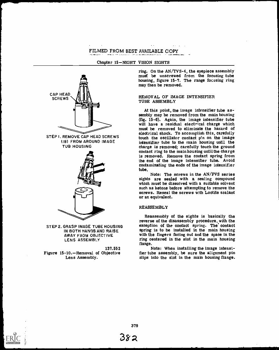
FILMED FROM BEST AVAILABLE COPY
Chapter 15NIGHT VISION SIGHTS
CAP HEADSCREWS
STEP I. REMOVE CAP HEAD SCREWS(18) FROM AROUND IMAGETUB HOUSING
STEP 2. GRASP IMAGE TUBE HOUSINGIN BOTH HANDS AND RAISEAWAY FROM OBJECTIVELENS ASSEMBLY
137.552Figure 15-10.Removal of Objective
Lens Assembly.
379
3k
ring. On the AN/TVS-4, the eyepiece assemblymust be unscrewed from the focusing tubehousing, figure 15-7. The range focusing ringmay then be removed.
REMOVAL OF IMAGE INTENSIFIERTUBE ASSEMBLY
At this point, the image intensifier tube as-sembly may be removed from the main housing(fig. 15-6). Again, the image intensifier tubewill have a residual electrical charge whichmust be removed to eliminate the hazard ofelectrical shock. To accomplish this, carefullytouch the oscillator contact pin on the imageintensifier tube to the main housing until thecharge is removed; carefully touch the groundcontact ring to the main housing until the chargeis removed. Remove the contact spring fromthe end of the image intensifier tube. Avoidcontaminating the ends of the image intensifiertube.
Note: The screws in the AN/PVS seriessights are sealed with a sealing compoundwhich must be dissolved with a suitable solventsuch as ketone before attempting to remove thescrews. Reseal the screws with Loctite sealantor an equivalent.
REASSEMBLY
Reassembly of the sights is basically thereverse of the disassembly procedure, with theexception of the contact spring. The contactspring is to be installed in the main housingwith the fingers facing out and the space in thering centered in the slot in the main housingflange.
Note: When installing the image intensi-fier tube assembly, be sure the alignment pinslips into the slot in the main housing flange.

A
Abberations of the eye, 101.104Advancement. in rating, 1-7
enlisted rating structure, 1Opticalman rating, 1rewards, 2-7
Assembling mechanical parts, 187Assembling prisms, 186Astigmatism, 84Astronomical telescope, 110-113Attachments and accessories of the lathe,212-218
Azimuth and bearing circles, 312-329collimation, 317-319construction features, 312-315disassembly, 324operating features, 315operation, 321-324overhaul and repair, 316, 325, 328principle of operation, 327reassembly and collimation, 325sextant, 319-321stadimeter, 325-327
B
Basic optical systems, 94-125eyepiece systems, 104-108eye structure, 95-104human eye, 94simple telescope, 108-125
Bearings, 141-144Binocular assembly, 353Binoculars, 336-356
hand-held binoculars, 336-348ship-mounted binocular, 348-356
Boresight telescopes, 281-287characteristics, 281-287disassembly, 287repair and reasembly, 287
Boring, 221
INDEX
C
Characteristics of night vision sights,574-377
optical system, 375-377Chromatic abberations, 79Cleaning and painting optical instruments,175-180
Collimation of an optical instrument, 187-196Color of light, 18Color vision, 19Coma, 82Compound lenses, 89Curvature of field, 82Cylir.drical lenses, 65
D
Degree system, 36Design and construction of optical instruments,126-154
lubrication, 153mechanical features, 126-130mounting optical elements, 131-147
Dewpoint test, 369Disassembly of optical instruments, 168-171Distortion in an image, 84Drill presses, 267-273
major assemblies, 267operating procedure, 269-273speeds and feeds, 268
Electromagnetic spectrum, 15External maintenance of the submarine tele-scope, 368-373
cycling equipment, 370cycling procedure, 371-373dewpoint test, 369drying equipment, 371
380

INDEX
Eyepiece systems, 104-108basic function, 105nomenclature, 105types, 105
Eye structure, 94-104abberations of the eye, 101-104an optical instrument, 95iris function, 96refracting mechanism, 95steroscopic vision, 100vision, 96-100
F
Focal length, 73Focusing arrangements, 134-141
G
Geneva lens measure, 166-168Grinders, 243-247
grinding safety, 243metals, 244-247
Grinding safety, 243Gunsight telescopes, 287-293
collimation, 292disassembly, 292drying and gassing, 293features, 288-202repair and reassembly, 292
H
Hand-held binoculars, 33(3.348collimation, 346-348disassembly, 341-344features, 337-341reassembly, 344-346
Heat treating and tempering, 201Heat treating processes, 203-206How to prepare for advancement, 5-7How to qualify for advancement, 2-5Human eye, 94
I
Illumination and contrast, 162-164Image description, 36-39
image attitude, 37-39real image, 36virtual image, 37
Image formation, 58-65Image transmission, 39-49
penta prism, 48plane mirrors, 39-42reflecting prisms, 43-46refracting prisms, 42rhomboid prism, 46
Index of refraction, 26-28Inspecting and testing optical instruments,155-180
cleaning and painting, 175-180common tools, 164disassembly, 168-171geneva lens measure, 166-168illumination and contrast, 162-164inspection of instruments, 155-159overhaul and repair, 164repair procedure, 172-175special tools, 184testing of instruments, 159-162
Inspection of instruments, 155-159Instrument sealing methods, 147-149Iris function, 96
381
L
Lathes, 207-242attachments and accessories, 212-218cutting tools, 218-223knowledge of operation, 223- :A2principal parts, 207-212safety precautions, 242
Laws of refraction, 24-26Len cleaning and cementing, 180-184
cementing equipment and materials, 182cleaning equipment, 180cleaning procedure, 181recementing, 183separating cemented elements, 183types of cement, 182
Lens abberations, 79-86astigmatism, 84chromatic abberatioi:s, 79coma, 82curvature of field, 82distortion, 84Newton's rings, 85spherical abberations, 80-82
Lens combinations, 90Lenses, 50-93
lens abberations, 79-86lens formulas, 72-79thick lenses, 86-93thin lenses, 52-72

OPTICALMAN 3 & 2
Lens formulas, 72-79focal length, 73magnification, 73-77relative aperture, 78relative image brightness, 79
Lens mounts, 131-134Lens terminology, 52-58Light theories, 8Lubrication of optical instruments, 153
instrument specifications, 154types of lubricants, 154
M
Machine tool operationpart I, 207-242lathes, 207-242
Machine tool operationpart II, 243-273drill presses, 267-273grinders, 243-247milling machines, 247-267
Magnetic compass, 300-312compass error, 304disassembly, 304-306principle of operation, 301-304repair and reassembly, 306-311testing and adjusting, 311
Magnification by an optical element, 73-77Maintenance, 378
disassembly of electrical system, 378reassembly, 379removal of eyepiece assembly, 378removal of image intensifier tube assem-bly, 379
removal of objective lens assembly, 378Maintenance procedurespart I, 155-184
inspection and testing, 155-180len cleaning and cementing, 180-184
Maintenance procedurespart II, .185-206heat treating and tempering, 201heat treating processes 203-206reassembly and collimation, 185-201types of metals, 202
Measurements in optics, 35degree system, 36metric system, 35navy mil, 36
Mechanical features of optical instruments,120-130
body housing, 126-129diaphragms, 129shades and caps, 129
Metric system, 35Microscope, 124
382
Milling machines, 247-267coolants, 261feeds and speeds, 260machine operation, 262-266precautions, 266set up procedures, 254-260standard equipment, 249-254types of, 247-249
Mirrors and prisms, 35-49image description, 36-39image transmission, 39-49measurements in optics, 35
Miscellaneous optical elements, 91-93Mk 74 telescope, 288-290Mk 79 telescope, 290-292Mounting optical elements, 131-147
bearings, 141-144focusing arrangements, 134-141instrument sealing methods, 147-149lens mounts, 131-134optical instrument gears, 145-147packing, 152preformed gaskets, 149-152prism mounts, 134
N
Nature of light, 8-34theory and source of light, 8-19visibility of objects, 19-34
Navigation instruments, 300-335azimuth and bearing circles, 312-329magnetic compass, 300-312telescopic alitinde, 329-335
NavPers 10052; 6Navy mil, 36Newton's rings, 85Night vision sights, 374-379
characteristics of night vision sights,374-377
maintenance, 378premaintenance inspections, 377safety precautions, 377
0
OOD and QM spyglasses, 274-281collimation, 280disassembly, 276-280features, 275repair and reassembly, 280
Optical instrument gears, 145-147

INDEX
Opticalman billets, 1Opticalman rating, 1Overhaul and repair of optical instruments,164
P
Packing optical instruments, 152Preformed gaskets, 149-152Premaintenance inspections, 377
electrical, 378optical and mechanical, 377
Principal parts of the lathe, 207-212Prism mc...,nts, 134
Qua ls manual, 5
Q
R
Rate training manuals, 6Reassembly and collimation of optical instru-ments, 185-201
assembling mechanical parts, 187assembling prisms, 186collimation, 187-196replacing lens, 185sealing, drying, and charging, 196-201
Record of practical factors, 5Reflection, 21-23Fteflection and refraction combined, 28Refraction, 23-31Relative Aperture, 78Relative image brightness, 79Removal and installation of the submarinetelescope, 363-368
external fittings, 364-368storage, 368
Repair procedure for optical instruments,172-175
Replacing lens, 185
S
Sealing, drying, and charging optical instru-ments, 196-201
Selective reflection and absorption, 18Setting up the milling machine, 254-260Ship-mounted binoculars, 348-356
characteristics, 349-351collimation, 355
383
3
Ship-mounted binocularscontinuedmaintenance, 351-355sealing and charging, 355
Ship telescopes, 293-299characteristics, 294-296collimation, 298disassembly, 296repair and reassembly, 297
Simple telescope, 108-125astronomical, 110-113gunsight telescopes, 119-121microscope, 124telescope magnification, 121-124terrestrial telescopes, 113-119
Source of light, 9Speed of light, 15-18Spherical abberations, 80-82Spherical mirrors, 66-72Steroscopic vision, 100Submarine telescopes, 357-373
design designation, 257-362external maintenance, 368-373removal and installation, 363-368type 8B periscope, 362
T
Telescope magnification, 121-124Telescopes, 274-299
boresight telescopes, 281-287gunsight telescopes, 287-293OOD and QM spyglasses, 274-281ship telescopes, 293-299
Telescopic alidade, 329-335characteristics, 329-333operating principles, 333repair, 334
Terrestrial telescopes, 113-119Theory and source of light, 8-19
color of light, 18color vision, 19electromagnetic spectrum, 15light theories, 8selective reflection and absorption, 18source of light, 9speed of light, 15-18transmission of light, 10-14wavelength and frequency, 14
Thick lenses, 86-93back focal length, 89compound lenses, 89equivalent fecal length, 89front focal length, 89lens combinations, 90miscellaneous optical elements, 91-93

OPTICALMAN 3 & 2
Thin lenses, 52-72cylindrical lenses, 65image formation, 58-65lens terminology, 52-58physical description, 52spherical mirrors, 66-72
Transmission of light, 10-14Type 8B periscope, 362Types of metals, 202Types of milling machines, 247-249
384
V
Visibility of objects, 19-34atmospheric refraction, 31-34opaque objects, 20reflection, 21-23refraction, 23-31translucent, 20
Vision, 96-100
*U. S. GOVERNMENT PRINTING OFFICE 1971 31.5,4f12
Related Documents