HAL Id: hal-01982516 https://hal.archives-ouvertes.fr/hal-01982516v9 Preprint submitted on 26 Nov 2021 (v9), last revised 4 Aug 2022 (v10) HAL is a multi-disciplinary open access archive for the deposit and dissemination of sci- entific research documents, whether they are pub- lished or not. The documents may come from teaching and research institutions in France or abroad, or from public or private research centers. L’archive ouverte pluridisciplinaire HAL, est destinée au dépôt et à la diffusion de documents scientifiques de niveau recherche, publiés ou non, émanant des établissements d’enseignement et de recherche français ou étrangers, des laboratoires publics ou privés. Theoretical calculation of the power of wind turbine or tidal turbine Pierre Normandajc Lecanu, Bertil Smorgrav, Dominique Mouazé To cite this version: Pierre Normandajc Lecanu, Bertil Smorgrav, Dominique Mouazé. Theoretical calculation of the power of wind turbine or tidal turbine. 2021. hal-01982516v9

Welcome message from author
This document is posted to help you gain knowledge. Please leave a comment to let me know what you think about it! Share it to your friends and learn new things together.
Transcript

HAL Id: hal-01982516https://hal.archives-ouvertes.fr/hal-01982516v9Preprint submitted on 26 Nov 2021 (v9), last revised 4 Aug 2022 (v10)
HAL is a multi-disciplinary open accessarchive for the deposit and dissemination of sci-entific research documents, whether they are pub-lished or not. The documents may come fromteaching and research institutions in France orabroad, or from public or private research centers.
L’archive ouverte pluridisciplinaire HAL, estdestinée au dépôt et à la diffusion de documentsscientifiques de niveau recherche, publiés ou non,émanant des établissements d’enseignement et derecherche français ou étrangers, des laboratoirespublics ou privés.
Theoretical calculation of the power of wind turbine ortidal turbine
Pierre Normandajc Lecanu, Bertil Smorgrav, Dominique Mouazé
To cite this version:Pierre Normandajc Lecanu, Bertil Smorgrav, Dominique Mouazé. Theoretical calculation of the powerof wind turbine or tidal turbine. 2021. �hal-01982516v9�
Theoretical Calculation of Wind (Or Water) Turbine
Pierre Lecanu 1 ID , Bertil Smorgrav 2 , Dominique Mouazé 3 ID
November 25, 2021
1 P. Lecanu,(Corresponding author) AjcInnov, 7 chemin du Mont Desert 14400 Esquay sur Seulles, France
E-mail address, [email protected]
2 B. Smorgrav, eXeco, 14000 Caen, France
3 Dominique Mouazé , Normandie Université, UNICAEN, UNIROUEN, CNRS, M2C, 14000 Caen, France
Abstract : The Betz limit sets a theoretical upper limit for the energy output of turbines, expressedas a maximum power coe�cient of 16/27. Betz's theory is precise and is based on the calculation of kineticenergy. By taking into account the potential energy, the theoretical energy output of the turbines can behigher. For fast wind turbines, the kinetic energy of the wind is optimally recovered and at the same time alarge amount of potential energy is created without additional energy input. The article presents a review ofthe consideration of this potential energy and it is possible for a wind turbine to transform potential energyinto kinetic energy. The de�nition of the maximum power coe�cient is the one established by Betz whichremains valid for the horizontal axis turbine HAWT and no longer makes sense for vertical axis turbinesVAWT. The results given are examined a conversion of the potential energy into kinetic energy through amechanical system which is not applicable for horizontal axis turbines HAWT.
Keywords : Betz limit, Betz's law, Wind turbine, Tidal turbine, HAWT, VAWT.
1 Introduction
Lanchester, Betz, Joukowsky van Kuik (2007) have participated in the de�nition of the maximum powercoe�cient of a wind turbine. This limit is commonly called Betz limit. Huge research e�orts have been madeto optimize wind turbines to approach this limit, for example by optimizing the angle of incidence, the shapeof the blade pro�le, etc. One can refer for example to the book "Wind Energy Handbook"Burton et al. forfast moving horizontal axis wind turbines (HAWT) or for example "Wind Turbine Design: With Emphasison Darrieus Concept" Paraschivoiu (2002) for vertical axis wind turbines (VAWT).Research has been done to improve this e�ciency by, for example, ducting the turbine (Georgiou (2016)Georgiou and Theodoropoulos (2016)) or by placing a water turbine in a narrow channel, which allows thewater level upstream to be increased by the resistance to the advancing �uid (Quaranta (2018) (Quaranta(2018))) or grouping turbines in farm in order to create an excess of power due to the proximity betweenmachines (ducting e�ect) ( Vennell (2013) Vennell (2013) and Broberg (2018) Broberg et al. (2018)).Betz' theory is based on the calculation of kinetic energy. A wind turbine is de�ned according to the energyof the �uid for energy recovery and for the de�nition of its structure to resist. A carriage that can movefreely, will be moved by the wind and will be subject to very little stress from the wind. If the carriage isstopped, the carriage will be subject to high stress on its structure. For a fast moving wind turbine, when thewind increases, the possible energy recovery increases and the stresses on its structure also increases, whichis not the same situation as for the carriage.
Large wind turbines are stopped when the wind becomes too strong, not because they produce too much,but because they are under too much stress which may break their blades. Stresses in a structure are potentialenergy.Betz's theory does not take into account the notion of stress (potential energy) for a wind turbine, it doesnot take into account only the notion of kinetic energy.
1

For a sailboat, a sail cannot recover all the energy of the wind. Betz' theory applies to the sail. At the kineticenergy level, the sail can only recover at most 60% (16/27) of the kinetic energy contained in the wind.Many books present this limit, such as John Kimball's book "Physics of Sailing"Kimball (2009). The AmericaCup race is a good example that a sailing boat equipped with hydrofoils is very e�cient.The kinetic energy of the wind is used to move the boat forward. The additional kinetic energy to lift theboat and to optimize the boat's performance is also created by the kinetic energy of the wind.The wind has not been doubled, but instead of creating stress on a keel, it is potential energy that istransformed into kinetic energy by a �uid �ow around a wing pro�le.The article presents the notion of kinetic energy and the notion of potential energy. It also presents that itis possible for a wind turbine to transform potential energy into kinetic energy.
2 Preliminary considerations of Betz's theory
The German mathematician A. Betz has shown that the power of turbine is (cf. Appendix 14, Betz (1920)):
Pk = F V = [Cka
1
2ρ S V 2
fluid] a Vfluid = Ck1
2ρ S V 3
fluid
where V = a Vfluid and Ck = 4a2(1− a)
Pk the kinetic turbine power, (W )Ck the kinetic power coe�cient,ρ the �uid density,( kgm3 )Vfluid the �uid velocity.(ms )V the �uid velocity at the position of the turbine.S the swept area.(m2)According to the work of Betz, a kinetic energy approach shows that the maximum power coe�cient Ck
can not exceed a maximum of 1627
Ck Betz =16
27Ck ≤ Ck Betz Pk maxi = Ck Betz
1
2ρ S V 3
fluid (1)
Figure 1. three-bladed VAWT wind turbine.;
The relative speed due to the rotation speed of the wind turbine and the �uid speed creates an inducedforce F on the pro�le. This induced force F can be broken down into an axial force Fa and a normal forceFn. The axial force Fa associated with the radius R creates a driving torque to produce energy. The normalforce Fn associated with the same radius R creates a bending stress on the blade.
2

The power of the torque due to the axial forces and the angular speed of rotation of the wind turbine islimited to the 60% (16/27) of the kinetic power in the wind.
The force Fn is much greater than the force Fa. Both forces are associated with the same radius andhave the same origin the �uid velocity. These constraints are the source of internal energy. Constraints arepotential energy. Betz's theory does not take into account this potential energy which is as important as thekinetic energy. The theory behind Betz's limit is correct. However, it only takes into account the kineticenergy. In order to increase the e�ciency of wind and hydrokinetic turbines, they should be designed totransform the potential energy into kinetic energy.it is necessary to dissociate the slow speed turbines and the fast speed turbines.λ = ωR
Vfluidis an important parameter which makes a di�erence in the behavior of the turbines in front of
the wind.As for the sail, it is necessary to dissociate the navigation in thrust (square sail, spinnaker) (unstuck �ow)and the navigation in smoothness (wing pro�le sail) (laminar �ow)
3 di�erence between a low speed turbine and a high speed turbine
3.1 The advantage of using an airplane wing
FnF
Fa
W (relative speed)
U = ωR
Vfluid
Fn
Vfluid
ωR
W
Vfluid
Fn
Vfluid
Fn
Figure 2. comparison of low and high speed turbine.;The cups of an anemometer are almost free of stress, if the anemometer is free of charge. If the rotation
of the anemometer is blocked, the cups are subjected to stress.In the case of a wing pro�le, it's completely di�erent. The tangential rotational speed U of the pro�le istransverse to the air �ow of the �uid.The relative speed W due to the rotational speed U and the �uid speed Vfluid creates an induced force Fon the pro�le. The axial component Fa of this force F, combined with the radius, creates a driving torque.For horizontal axis wind turbines (HAWT) this torque allows to improve the e�ciency closed to that theone de�ned by Betz. Adding a transverse speed U will optimize the e�ciency de�ned by Betz, but will addsigni�cant stress on the wind turbine due to the normal component Fn of force F. That's why HAWT wind
3
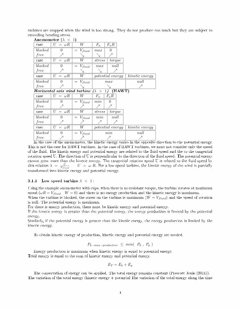
turbines are stopped when the wind is too strong. They do not produce too much but they are subject toexceeding bending stress.
Anemometer (λ < 1)case U = ωR W Fn FnR
blocked 0 = Vfluid max 0free ↗ ↘ ↘ ↗case U = ωR W stress torque
blocked 0 = Vfluid max nullfree ↗ ↘ ↘ ↗case U = ωR W potential energy kinetic energy
blocked 0 = Vfluid max nullfree ↗ ↘ ↘ ↗
Horizontal axis wind turbine (λ > 1) (HAWT)case U = ωR W Fn FaR
blocked 0 = Vfluid min 0free ↗ ↗ ↗ ↗case U = ωR W stress torque
blocked 0 = Vfluid min nullfree ↗ ↗ ↗ ↗case U = ωR W potential energy kinetic energy
blocked 0 = Vfluid min nullfree ↗ ↗ ↗ ↗
In the case of the anemometer, the kinetic energy varies in the opposite direction to the potential energy.This is not the case for HAWT turbines. In the case of HAWT turbines, we must not consider only the speedof the �uid. The kinetic energy and potential energy are related to the �uid speed and the to the tangentialrotation speed U. The direction of U is perpendicular to the direction of the �uid speed. The potential energycannot grow more than the kinetic energy. The tangential rotation speed U is related to the �uid speed bythis relation λ = U
VfluidU = ω R. For a low speed turbine, the kinetic energy of the wind is partially
transformed into kinetic energy and potential energy.
3.1.1 Low speed turbine λ < 1 :
Using the example anemometer with cups, when there is no resistant torque, the turbine rotates at maximumspeed (ωR = Vfluid W = 0) and there is no energy production and the kinetic energy is maximum.When the turbine is blocked, the stress on the turbine is maximum (W = Vfluid) and the speed of rotationis null. The potential energy is maximum.For there is energy production, there must be kinetic energy and potential energy.If the kinetic energy is greater than the potential energy, the energy production is limited by the potentialenergy.Similarly, if the potential energy is greater than the kinetic energy, the energy production is limited by thekinetic energy.
To obtain kinetic energy of production, kinetic energy and potential energy are needed.
Pk−max−productive ≤ min( Pk , Pp )
Energy production is maximum when kinetic energy is equal to potential energy.Total energy is equal to the sum of kinetic energy and potential energy.
ET = Ek + Ep
The conservation of energy can be applied. The total energy remains constant (Prescott Joule (2011)).The variation of the total energy (kinetic energy + potential The variation of the total energy along the time
4
is zero.
dEtotaldt
= 0 → dEkdt
= − dEpdt
(2)
The potential energy is related to the relative speed W . The kinetic energy is related to the relative speedωR (see Figure 2).The tangential rotation speed must be equal to half of the �uid speed to have the optimal conditions.
|Vfluid| = |U |+ |W | |U | = |W | U = ωR =Vfluid
2λ =
1
2(3)
To have an energy production, the maximum power of the kinetic energy of a turbine at low speed (λ <1 λ = ωR
Vfluid) is equal to
Pk max(with λ<1) = Ck(with λ<1)1
2ρSV 3
fluid Ck max(with λ<1) =1
2(4)
For a low speed turbine, the kinetic energy of the wind is partially transformed into kinetic energy andpotential energy.
Ekwind ⇒ Ek & Ep
3.1.2 Fast speed turbine λ > 1 :
For fast moving turbines, as the �uid speed increases, the potential energy and kinetic energy increase.The maximum power of the energy is de�ned by the Betz limit
Pk max(with λ>1) = Ck(Betz)1
2ρSV 3
fluid Ck(Betz) =16
27(5)
Energy production is related to kinetic energy and potential energy. Potential energy and kinetic energycannot be separated to determine the maximum energy production.The kinetic energy of the �uid is transformed partly into potential energy 8 and then into kinetic energy 9.
Ekwind ⇒ Ep ⇒ Ek
4 Summary calculation sheet for fast moving turbines
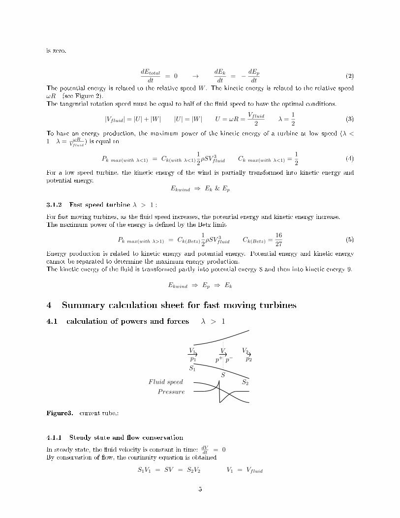
4.1 calculation of powers and forces λ > 1
V1 V V2p+ p− p2p1
Pressure
F luid speed
S1
SS2
Figure3. current tube.;
4.1.1 Steady state and �ow conservation
In steady state, the �uid velocity is constant in time: dVdt = 0
By conservation of �ow, the continuity equation is obtained
S1V1 = SV = S2V2 V1 = Vfluid
5
4.1.2 Energy, power and kinetic force
The index k for "kinetic" is used
Ek =1
2mv2 Pk =
dEkdt
=1
2
dm
dtv2+
1
2mdv2
dt
dv
dt= 0 m = ρsvdt Pk =
1
2ρsv3 Fk =
Pkv
=1
2ρsv2
4.1.3 Energy, power and potential force
The index p for "potential" is used
Ek = mp
ρPp =
dEpdt
=dm
dt
p
ρ+m
1
ρ
dp
dt
dp
dt= 0 m = ρsvdt Pp = svp Fp =
Ppv
= ps
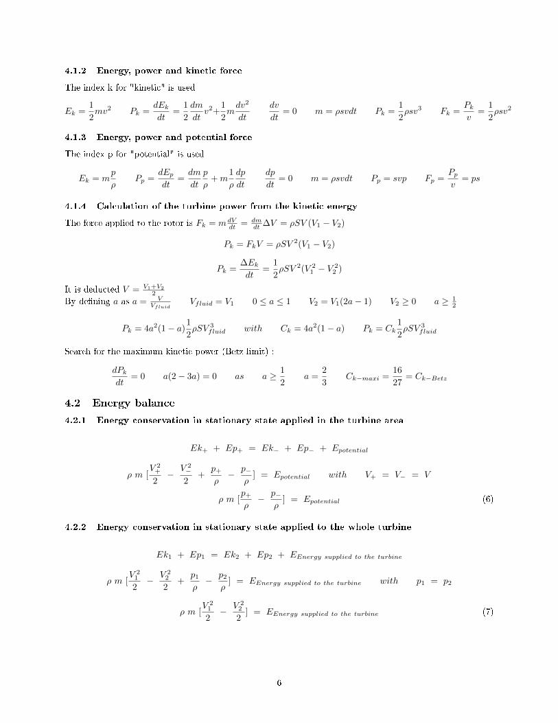
4.1.4 Calculation of the turbine power from the kinetic energy
The force applied to the rotor is Fk = mdVdt = dm
dt ∆V = ρSV (V1 − V2)
Pk = FkV = ρSV 2(V1 − V2)
Pk =∆Ekdt
=1
2ρSV 2(V 2
1 − V 22 )
It is deducted V = V1+V2
2
By de�ning a as a = VVfluid
Vfluid = V1 0 ≤ a ≤ 1 V2 = V1(2a− 1) V2 ≥ 0 a ≥ 12
Pk = 4a2(1− a)1
2ρSV 3
fluid with Ck = 4a2(1− a) Pk = Ck1
2ρSV 3
fluid
Search for the maximum kinetic power (Betz limit) :
dPkdt
= 0 a(2− 3a) = 0 as a ≥ 1
2a =
2
3Ck−maxi =
16
27= Ck−Betz
4.2 Energy balance
4.2.1 Energy conservation in stationary state applied in the turbine area
Ek+ + Ep+ = Ek− + Ep− + Epotential
ρ m [V 2+
2−
V 2−2
+p+ρ− p−
ρ] = Epotential with V+ = V− = V
ρ m [p+ρ− p−
ρ] = Epotential (6)
4.2.2 Energy conservation in stationary state applied to the whole turbine
Ek1 + Ep1 = Ek2 + Ep2 + EEnergy supplied to the turbine
ρ m [V 21
2− V 2
2
2+
p1ρ− p2
ρ] = EEnergy supplied to the turbine with p1 = p2
ρ m [V 21
2− V 2
2
2] = EEnergy supplied to the turbine (7)
6

4.2.3 remark
The Bernoulli equations
p1 +1
2ρs1V1 = p+ +
1
2ρsV p− +
1
2ρsV = p2 +
1
2ρs2V2
V1 = Vfluid P1 = P2 → V 21
2− V 2
2
2=
p+ρ− p−
ρ
by using equations (8),(9)Epotential = EEnergy supplied to the turbine
The kinetic energy of the �uid is partially transformed into potential energy and then into kinetic energy
4.3 Energy conservation for the fast speed turbine λ > 1
V1 V V2p+ p− p2p1
Pressure
F luid speed
Figure3. current tube.;Energy conservation in stationary state applied in the turbine area :
Ek+ + Ep+ = Ek− + Ep− + Epotential
ρ m [V 2+
2−
V 2−2
+p+ρ− p−
ρ] = Epotential with V+ = V− = V
ρ m [p+ρ− p−
ρ] = Epotential (8)
Energy conservation in stationary state applied to the whole turbine (HAWT or VAWT) :
Ek1 + Ep1 = Ek2 + Ep2 + EEnergy supplied to the turbine
ρ m [V 21
2− V 2
2
2+
p1ρ− p2
ρ] = EEnergy supplied to the turbine with p1 = p2
ρ m [V 21
2− V 2
2
2] = EEnergy supplied to the turbine (9)
The kinetic energy of the wind is transformed initially into potential energy and then intokinetic energy.
Ekwind ⇒ Ep ⇒ Ek
5 Conversion of potential energy into additional kinetic energy
There can be energy production only if we have kinetic energy and potential energy.For a sailboat, Betz' theory applies Kimball (2009) . The �uid �ow due to the wind and the forward speedof the sailboat creates an induced force on the sail. A small part of this force is used to move the sailboatforward, the other part creates stress on the sail and causes the boat to heel. Constraints are created onthe keel to resist the heel. Instead of having static stresses on the keel, the trick of using hydrofoils allowsa kinetic �ow. This �ow lifts the sailboat, creates a reaction force against the tilt and greatly improves theperformance of the sailboat. The principle of transforming potential energy into kinetic energy increasesperformance and the wind has not been doubled.
7
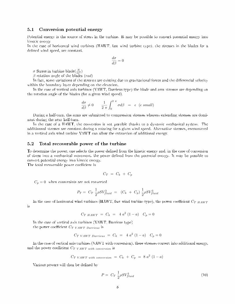
5.1 Conversion potential energy
Potential energy is the source of stress in the turbine. It may be possible to convert potential energy intokinetic energyIn the case of horizontal wind turbines (HAWT, fast wind turbine type), the stresses in the blades for ade�ned wind speed, are constant.
dσ
dβ= 0
σ Stress in turbine blade( Nm2 )β rotation angle of the blades (rad)In fact, some variations of the stresses are existing due to gravitational forces and the di�erencial velocity
within the boundary layer depending on the elevation.In the case of vertical axis turbines (VAWT, Darrieus type) the blade and arm stresses are depending on
the rotation angle of the blades (for a given wind speed).
dσ
dβ6= 0
1
2 π
∫ 2 π
0
σdβ = ε (ε small)
During a half-turn, the arms are submitted to compression stresses whereas extending stresses are domi-nant during the next half-turn.
In the case of a HAWT, the conversion is not possible thanks to a dynamic mechanical system. Theadditionnal stresses are constant during a rotating for a given wind speed. Alternative stresses, encounteredin a vertical axis wind turbine VAWT can allow the extraction of additional energy.
5.2 Total recoverable power of the turbine
To determine the power, one selects the power de�ned from the kinetic energy and, in the case of conversionof stress into a mechanical movement, the power de�ned from the potential energy. It may be possible toconvert potential energy into kinetic energy.The total recoverable power coe�cient is
CT = Ck + Cp
Cp = 0 when constraints are not converted
PT = CT1
2ρSV 3
fluid = (Ck + Cp)1
2ρSV 3
fluid
In the case of horizontal wind turbines (HAWT, fast wind turbine type), the power coe�cient CT HAWT
is
CT HAWT = Ck = 4 a2 (1− a) Cp = 0
In the case of vertical axis turbines (VAWT, Darrieus type)the power coe�cient CT V AWT Darrieus is
CT V AWT Darrieus = Ck = 4 a2 (1− a) Cp = 0
In the case of vertical axis turbines (VAWT with conversion), these stresses convert into additional energy,and the power coe�cient CT V AWT with conversion is
CT V AWT with conversion = Ck + Cp = 8 a2 (1− a)
Various powers will then be de�ned by
P = CT1
2ρSV 3
fluid (10)
8
PT HAWT = 4 a2 (1− a)1
2ρSV 3
fluid (11)
PT V AWT Darrieus = 4 a2 (1− a)1
2ρSV 3
fluid (12)
PT V AWT with conversion = 8 a2 (1− a)1
2ρSV 3
fluid (13)
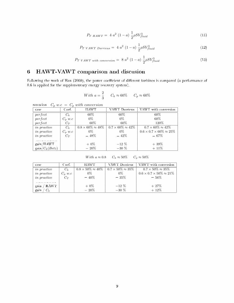
6 HAWT-VAWT comparison and discusion
Following the work of Hau (2000), the power coe�cient of di�erent turbines is compared (a performance of0.6 is applied for the supplementary energy recovery system).
With a =2
3Ck ≈ 60% Cp ≈ 60%
notation Cp w.c = Cp with conversioncase Coef. HAWT VAWT Darrieus VAWT with conversion
perfect Ck 60% 60% 60%perfect Cp w.c 0% 0% 60%perfect CT = 60% = 60% = 120%
in practice Ck 0.8× 60% ≈ 48% 0.7× 60% ≈ 42% 0.7× 60% ≈ 42%in practice Cp w.c 0% 0% 0.6× 0.7× 60% ≈ 25%in practice CT = 48% = 42% = 67%. . . . . . . . . . . . . .gain/HAWT + 0% −12 % + 39%gain/Ck(Betz) − 20% −30 % + 11%
With a ≈ 0.8 Ck ≈ 50% Cp ≈ 50%
case Coef. HAWT VAWT Darrieus VAWT with conversion
in practice Ck 0.8× 50% ≈ 40% 0.7× 50% ≈ 35% 0.7× 50% ≈ 35%in practice Cp w.c 0% 0% 0.6× 0.7× 50% ≈ 21%in practice CT = 40% = 35% = 56%. . . . . . . . . . . . .gain / HAWT + 0% −12 % + 27%gain / Ck − 20% −30 % + 12%
9

0.4 0.9a0
0.5
1.2
CT V AWT with conversion 0.7 ( Ck + 0.6 Cp)
CT Maxi 1.0 (Ck + Cp)
Cp Betz 1.0 Ck
CT HAWT 0.8 CkCT V AWT Darrieus 0.7 Ck
Ck = 4 a2 (1 − a)
Cp = 4 a2 (1 − a)]
Figure4. Tip speed ratio performance curve;
6.1 Active lift turbine project
The project "Active lift turbine" is a transformation example of potential energy into kinetic energy (seepreprint : Simpli�ed theory of an active lift turbine with controlled displacement (Lecanu et al. (2016).
Ck =9π
27b3 − 23
3b2 +
π
2b
Cp =e
Rλ(
9π
27b3 − 22
3b2 +
π
2b)
Cactiveliftturbine = (1 +e
Rλ)(
9π
27b3 − 22
3b2 +
π
2b)
with b = σλ
σ sti�ness coe�cientλ Tip speed ratioe eccentric distanceR Turbine radius
6.2 Synthesis scheme:
6.2.1 Low speed turbine λ < 1 :
case : λ < 1 � turbine type Anemometer with cups
10

Fluidenergy Pfluid = 1
2ρSV3fluid
Kineticenergy
U = ω R
Potentialenergy
Vfluid − U
Pkinetic + Ppotential < Pfluid
λ < 1 λ = ω RVfluid
optimum λ = 12 Coef = 1
2
P ∗k(max) = Coef 1
2ρSV3fluid
Energyproduction
Materialstrength
Conversion
Potential energy in kinetic energy
EnergyProduction
Eventually
∗ to obtain an energy production
6.2.2 Fast speed turbine HAWT or VAWT λ > 1 :
case : λ > 1 � large wind turbines HAWT or VAWT
Fluidenergy Pfluid = 1
2ρSV3fluid
Potentialenergy
Pk = Coef 12ρSV
3fluid
Coef generally Coef ≤ CkBetz
Kineticenergy
Pkinetic + Ppotential > Pfluid
λ > 1 λ = ω RVfluid
Energyproduction
Materialstrength
Conversion
Potential energy in kinetic energy
EnergyProduction
Eventually
In the case of a turbine with a lambda lower than 1, Of the recoverable energy , a part is transformedinto kinetic energy and the other part into potential energy (stress in the turbine). Eventually a part of thispotential energy could be transformed into kinetic energy.
In the case of a turbine with a lambda greater than 1, the recoverable energy de�ned by Betz, is trans-formed into potential energy. This energy creates kinetic energy and also creates potential energy (stress inthe turbine). This is possible because we have created a speed of rotation higher than the speed of the �uid.A part of this potential energy (due to the stress) can be transformed into kinetic energy.
11
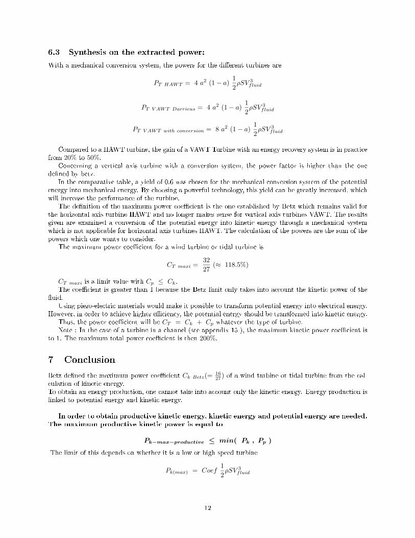
6.3 Synthesis on the extracted power:
With a mechanical conversion system, the powers for the di�erent turbines are
PT HAWT = 4 a2 (1− a)1
2ρSV 3
fluid
PT V AWT Darrieus = 4 a2 (1− a)1
2ρSV 3
fluid
PT V AWT with conversion = 8 a2 (1− a)1
2ρSV 3
fluid
Compared to a HAWT turbine, the gain of a VAWT Turbine with an energy recovery system is in practicefrom 20% to 50%.
Concerning a vertical axis turbine with a conversion system, the power factor is higher than the onede�ned by betz.
In the comparative table, a yield of 0.6 was chosen for the mechanical conversion system of the potentialenergy into mechanical energy. By choosing a powerful technology, this yield can be greatly increased, whichwill increase the performance of the turbine.
The de�nition of the maximum power coe�cient is the one established by Betz which remains valid forthe horizontal axis turbine HAWT and no longer makes sense for vertical axis turbines VAWT. The resultsgiven are examined a conversion of the potential energy into kinetic energy through a mechanical systemwhich is not applicable for horizontal axis turbines HAWT. The calculation of the powers are the sum of thepowers which one wants to consider.
The maximum power coe�cient for a wind turbine or tidal turbine is
CT maxi =32
27(≈ 118.5%)
CT maxi is a limit value with Cp ≤ Ck.The coe�cient is greater than 1 because the Betz limit only takes into account the kinetic power of the
�uid.Using piezo-electric materials would make it possible to transform potential energy into electrical energy.
However, in order to achieve higher e�ciency, the potential energy should be transformed into kinetic energy.Thus, the power coe�cient will be CT = Ck + Cp whatever the type of turbine.Note : In the case of a turbine in a channel (see appendix 15 ), the maximum kinetic power coe�cient is
to 1. The maximum total power coe�cient is then 200%.
7 Conclusion
Betz de�ned the maximum power coe�cient Ck Betz(=1627 ) of a wind turbine or tidal turbine from the cal-
culation of kinetic energy.To obtain an energy production, one cannot take into account only the kinetic energy. Energy production islinked to potential energy and kinetic energy.
In order to obtain productive kinetic energy, kinetic energy and potential energy are needed.The maximum productive kinetic power is equal to
Pk−max−productive ≤ min( Pk , Pp )
The limit of this depends on whether it is a low or high speed turbine
Pk(max) = Coef1
2ρSV 3
fluid
12
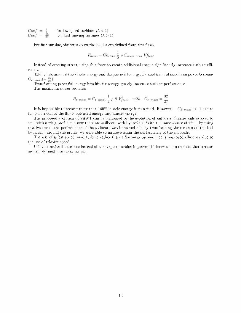
Coef = 12 for low speed turbines (λ < 1)
Coef = 1621 for fast moving turbines (λ > 1)
For fast turbine, the stresses on the blades are de�ned from this force.
Fmaxi = CkBetz1
2ρ Sswept area V
2fluid
Instead of creating stress, using this force to create additional torque signi�cantly increases turbine e�-ciency.
Taking into account the kinetic energy and the potential energy, the coe�cient of maximum power becomesCT maxi(=
3227 ):
Transforming potential energy into kinetic energy greatly increases turbine performance.The maximum power becomes
PT maxi = CT maxi1
2ρ S V 3
fluid with CT maxi =32
27
It is impossible to recover more than 100% kinetic energy from a �uid. However, CT maxi > 1 due tothe conversion of the �uids potential energy into kinetic energy.
The proposed evolution of VAWT can be compared to the evolution of sailboats. Square sails evolved tosails with a wing pro�le and now there are sailboats with hydrofoils. With the same source of wind, by usingrelative speed, the performance of the sailboats was improved and by transforming the stresses on the keelby �owing around the pro�le, we were able to improve again the performance of the sailboats.
The use of a fast speed wind turbine rather than a Savonius turbine means improved e�ciency due tothe use of relative speed.
Using an active lift turbine instead of a fast speed turbine improves e�ciency due to the fact that stressesare transformed into extra torque.
13
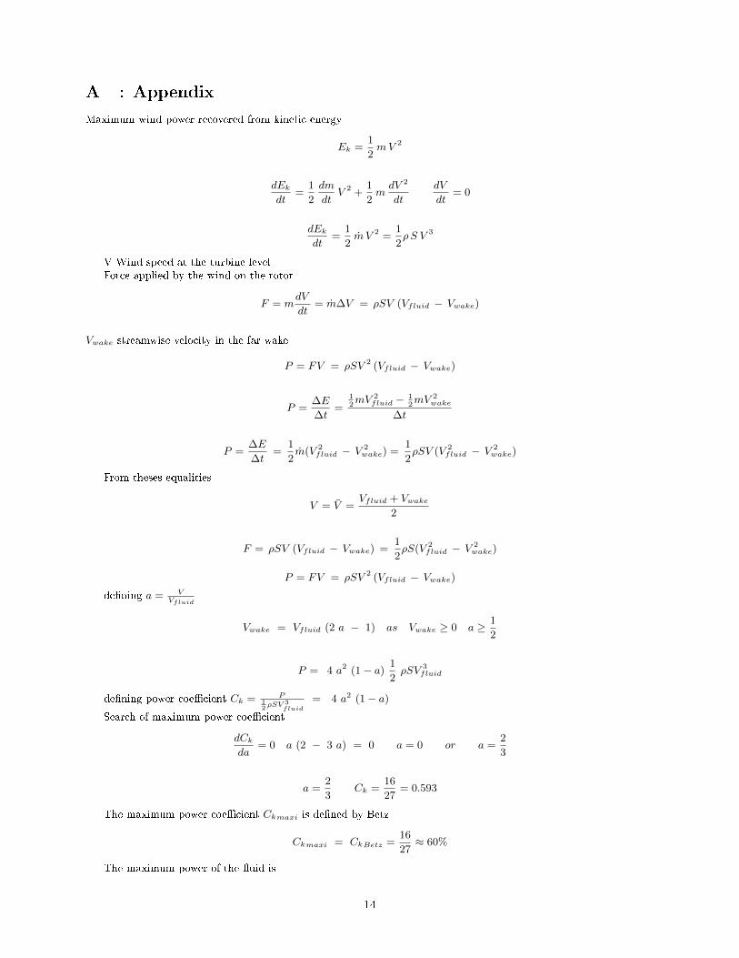
A : Appendix
Maximum wind power recovered from kinetic energy
Ek =1
2mV 2
dEkdt
=1
2
dm
dtV 2 +
1
2mdV 2
dt
dV
dt= 0
dEkdt
=1
2m V 2 =
1
2ρS V 3
V Wind speed at the turbine levelForce applied by the wind on the rotor
F = mdV
dt= m∆V = ρSV (Vfluid − Vwake)
Vwake streamwise velocity in the far wake
P = FV = ρSV 2 (Vfluid − Vwake)
P =∆E
∆t=
12mV 2
fluid − 12mV 2
wake
∆t
P =∆E
∆t=
1
2m(V 2
fluid − V 2wake) =
1
2ρSV (V 2
fluid − V 2wake)
From theses equalities
V = V =Vfluid + Vwake
2
F = ρSV (Vfluid − Vwake) =1
2ρS(V 2
fluid − V 2wake)
P = FV = ρSV 2 (Vfluid − Vwake)
de�ning a = VVfluid
Vwake = Vfluid (2 a − 1) as Vwake ≥ 0 a ≥ 1
2
P = 4 a2 (1− a)1
2ρSV 3
fluid
de�ning power coe�cient Ck = P12ρSV 3
fluid
= 4 a2 (1− a)
Search of maximum power coe�cient
dCkda
= 0 a (2 − 3 a) = 0 a = 0 or a =2
3
a =2
3Ck =
16
27= 0.593
The maximum power coe�cient Ckmaxi is de�ned by Betz
Ckmaxi = CkBetz =16
27≈ 60%
The maximum power of the �uid is
14

Pfluid =1
2ρSfluidV
3fluid
Sfluid = S VVfluid
= a S
The power of the turbine is
P =Cka
Pfluid = Ck1
2ρSfluida
V 3fluid = Ck
1
2ρSV 3
fluid
The maximum power of the turbine is
Pmax =Ck Betz
23
Pfluid =8
9Pfluid = Ck Betz
1
2ρSV 3
fluid =16
27(1
2ρSV 3
fluid)
Pmax = Ck Betz1
2ρSV 3
fluid (14)
15

B : Appendix
Maximum wind power for a turbine in a channel (from kinetic energy)
V = Vfluid V Vwake
S S Swake
Ek =1
2mV 2
dEkdt
=1
2
dm
dtV 2 +
1
2mdV 2
dt
dV
dt= 0
dEkdt
=1
2m V 2 =
1
2ρS V 3
V Wind speed at the turbine levelForce applied by the wind on the rotor
F = mdV
dt= m∆V = ρSV (V − Vwake)
Vwake streamwise velocity in the far wake
P = FV = ρSV 2 (V − Vwake)
P =∆E
∆t=
12mV 2 − 1
2mV 2
wake
∆t
P =∆E
∆t=
1
2m(V 2 − V 2
wake) =1
2ρSV (V 2 − V 2
wake)
From theses equalities
Vwake =1
2V Swake =
S V
Vwake= 2 S
F = ρSV (Vfluid − Vwake) =1
2ρS(V 2
fluid − V 2wake)
P = FV = ρSV 2 (Vfluid − Vwake)
P =1
2ρSV 3
fluid
de�ning power coe�cient
Ck =P
12ρSV 3
fluid
= 1 (15)
16

C : Appendix
Additional recovery power (from potential energy)The �uid creates stresses in the blade. They are due to thrust force. The energy of this force is
Ep = mfsρ
fs thrust forceFor HAWT horizontal wind turbines (fast wind turbine type), the thrust force Fs are constant.
dEpdt
= 0
For a VAWT, the thrust force depends on the time or the rotation angle Fs(t) or Fs(β) β = ω t
ω = dβdt
angular frequency
dEpdt
6= 0 and1
2 π
∫ 2 π
0
Ep(β)dβ = ε (ε small)
As
Fs = fsS = Cx1
2ρ S V 2
fluid
Ep = m Cx1
2V 2fluid
V �uid speed at the level turbineThe power is
Pp =dEpdt
dm = ρSV dt
Pp =dEpdt
=dm
dtCx
1
2S V 2
fluid + m Cx1
2SdV 2
fluid
dt
dVfluiddt
= 0
Pp = a Cx1
2ρ S V 3
fluid with a =V
Vfluid(16)
1
2 π
∫ 2 π
0
Ep(β)dβ = ε (ε small) Ep−max ≈ − Ep−min
the power depends on a potential energy di�erence
Pp =∆Ep∆t
T =2 π
ωPp ≤
Ep−max − Ep−minT
Pp ≤Ep−max
πω
for a half-turn
Ep(β) R dβ = dEp π R
in particular
Ep−max =dEpdβ
π =dEpdt
π
ω
AsdEpdt
= a Cx1
2ρ S V 3
fluid and Pp ≤Ep−max
πω
Pp ≤ a Cx1
2ρ S V 3
fluid
17

D : Appendix
Variation of energy in opposite sense
Along a streamline, the Bernoulli's equation is see Bernoulli (1738)
p
ρ+
v2
2= constant with z = 0
By multiplying by m
mp
ρ+ m
v2
2= constant
The di�erential of this equation is
d(1
2m v2) = − d(m
p
ρ) (17)
the variations of energy vary simultaneously and in opposite sense.
AsdV
dt= 0 and
dp
dt= 0 p = − 1
2ρ v2
18
References
D. Bernoulli. Hydrodynamica. doi:10.3931, eth-zurich e-rara-3911 edition, 1738.
A. Betz. Das maximum der theoretisch moglichen ausnutzung des windesdurch windmotoren. Zeitschrift furdas gesamte Turbinenwesen, 0(26):307�309, 1920.
D. Broberg, D. Shah, S. Drapcho, and A. Brockway. Getting more out of the wind: Extending betz's law tomultiple turbines. arXiv preprint arXiv:1805.01938, 2018.
T. Burton, N. Jenkins, D. Sharpe, and E. Bossanyi. Wind Energy Handbook, 2nd Edition, volume isbn=978-0-470-69975-1. Wiley.
D. Georgiou and N. Theodoropoulos. The loading of water current turbines: The betz limit and ductedturbines. Alternative Energy and Shale Gas Encyclopedia, pages 601�605, 2016.
E. Hau. Wind Turbines. Springer Germany, 2000.
J. Kimball. Physics of Sailing. CRC Press, 2009. ISBN 9781420073775. URL https://books.google.fr/
books?id=Xe_i23UL4sAC.
P. Lecanu, J. Bréard, and D. Mouazé. Simpli�ed theory of an active lift turbine with controlled displacement.Apr. 2016. URL https://hal.inria.fr/hal-01300531.
I. Paraschivoiu. Wind turbine design : with emphasis on darrieus concept, Jul 2002.
J. Prescott Joule. The Scienti�c Papers of James Prescott Joule, volume volume 1 : isbn= 978-0-470-69975-1.Cambridge Library Collection - Physical Sciences, 2011.
E. Quaranta. Stream water wheels as renewable energy supply in �owing water: Theoretical considerations,performance assessment and design recommendations. Energy for Sustainable Development, 45:96�109,2018.
G. A. van Kuik. The lanchester�betz�joukowsky limit. Wind Energy, 10(3):289�291, 2007. doi: https://doi.org/10.1002/we.218. URL https://onlinelibrary.wiley.com/doi/abs/10.1002/we.218.
R. Vennell. Exceeding the betz limit with tidal turbines. Renewable Energy, 55:277�285, 2013.
19
Related Documents