International RILEM Conference on Material Science – MATSCI, Aachen 2010 – Vol. I, ICTRC 153 THEORETICAL AND EXPERIMENTAL INVESTIGATIONS ON TEXTILE-REINFORCED CONCRETE SPALLING BEHAVIOR U. Reisgen, J. Schoene, M. Schleser, Institute of Welding and Joining, RWTH Aachen University, Germany J. Jeřábek, Institute of Structural Statics and Dynamics, RWTH Aachen University, Germany A. Keil, Institute of Building Materials Research; RWTH Aachen University, Germany ABSTRACT: The composite of a concrete matrix combined with technical textiles is investigated for several years now in the Collaborative Research Centre 532 (SFB 532) at RWTH Aachen University. The anisotropic properties of the material and the thin concrete layer lead to a spalling effect under high tensile load. The experimentally observed failure patterns are first classified and the performed experiment design is explained and discussed. A variety of tensile tests provided the basis for numerical analysis of the effect. The applied numerical model was designed in order to capture the initiation and propagation of longitudinal cracks leading to the separation of concrete from the textile fabrics. In consequence an experimental method was developed in order to confirm the numerically identified failure mechanisms. The paper presents the study of spalling based on both experimental and numerical investigations. 1 INTRODUCTION Recent experimental studies revealed that textile-reinforced concrete (TRC) specimens produced using a typical alkali resistant glass rovings exhibit low efficiency in terms of significant reduction of the maximum carrying force compared to the theoretical yarn strength [Vos08]. This is caused alongside the unavoidable boundary effects by the poor penetration of the cementitious matrix. In consequence a large fraction of inner filaments has low or no contact to the matrix and does not contribute to the overall crack bridging force. As shown experimentally in [Schl06] impregnation of the textile structures with high-modulus polymers can significantly increase the load-bearing capacities of TRC-components. The enhancement of the mechanical performance is accompanied with an altered failure pattern, which has not been observed for non-impregnated textile fabrics. Starting at a tensile load level of about 1000 N/mm² the tensions locally induced into the concrete lead to longitudinal cracks, which cause, in combination with the existing transverse cracks, spalling of large dimensions. So far, the major factors affecting the spalling have not been investigated. The aim is to prevent the specimens from spalling in order to improve the usability and performance of the TRC component especially under complex loads. In order to classify and characterize the spalling effects the experimental and numerical study was performed. In its experimental part the crack development of component tensile tests was recorded with the emphases on the time and spatial development of the longitudinal cracks. Based on these investigations a mechanical hypothesis was developed, identifying essential failure mechanisms. Following those findings a simplified set-up was proposed and a verification study was performed.

Welcome message from author
This document is posted to help you gain knowledge. Please leave a comment to let me know what you think about it! Share it to your friends and learn new things together.
Transcript
International RILEM Conference on Material Science – MATSCI, Aachen 2010 – Vol. I, ICTRC 153
THEORETICAL AND EXPERIMENTAL INVESTIGATIONS ON TEXTILE-REINFORCED CONCRETE SPALLING BEHAVIOR
U. Reisgen, J. Schoene, M. Schleser, Institute of Welding and Joining, RWTH Aachen University, Germany J. Jeřábek, Institute of Structural Statics and Dynamics, RWTH Aachen University, Germany A. Keil, Institute of Building Materials Research; RWTH Aachen University, Germany
ABSTRACT: The composite of a concrete matrix combined with technical textiles is investigated for several years now in the Collaborative Research Centre 532 (SFB 532) at RWTH Aachen University. The anisotropic properties of the material and the thin concrete layer lead to a spalling effect under high tensile load. The experimentally observed failure patterns are first classified and the performed experiment design is explained and discussed. A variety of tensile tests provided the basis for numerical analysis of the effect. The applied numerical model was designed in order to capture the initiation and propagation of longitudinal cracks leading to the separation of concrete from the textile fabrics. In consequence an experimental method was developed in order to confirm the numerically identified failure mechanisms. The paper presents the study of spalling based on both experimental and numerical investigations.
1 INTRODUCTION
Recent experimental studies revealed that textile-reinforced concrete (TRC) specimens produced using a typical alkali resistant glass rovings exhibit low efficiency in terms of significant reduction of the maximum carrying force compared to the theoretical yarn strength [Vos08]. This is caused alongside the unavoidable boundary effects by the poor penetration of the cementitious matrix. In consequence a large fraction of inner filaments has low or no contact to the matrix and does not contribute to the overall crack bridging force. As shown experimentally in [Schl06] impregnation of the textile structures with high-modulus polymers can significantly increase the load-bearing capacities of TRC-components. The enhancement of the mechanical performance is accompanied with an altered failure pattern, which has not been observed for non-impregnated textile fabrics.
Starting at a tensile load level of about 1000 N/mm² the tensions locally induced into the concrete lead to longitudinal cracks, which cause, in combination with the existing transverse cracks, spalling of large dimensions. So far, the major factors affecting the spalling have not been investigated. The aim is to prevent the specimens from spalling in order to improve the usability and performance of the TRC component especially under complex loads.
In order to classify and characterize the spalling effects the experimental and numerical study was performed. In its experimental part the crack development of component tensile tests was recorded with the emphases on the time and spatial development of the longitudinal cracks. Based on these investigations a mechanical hypothesis was developed, identifying essential failure mechanisms. Following those findings a simplified set-up was proposed and a verification study was performed.
154 REISGEN ET AL.: Theoretical and Experimental Investigations on TRC Spalling Behavior
2 EXPERIMENTAL STUDY OF THE SPALLING EFFECT
2.1 Materials
2.1.1 Rovings and textiles Rovings (yarns) of technical textiles consist of several hundred to several thousands of separate filaments with diameters of a few µm. After their production the filaments are sized with a blend of organic compounds. The size consists of a mixture of film formers, adhesives and antistatica [Sjö99] and facilitates subsequent processing of the glass fibers and reduces damage during production. Subsequently, the yarn is processed usually into two- or three-dimensional textiles fabrics like the one depicted in Fig. 2.1.
In the present study alkali resistant (AR-) glass rovings with a size produced by OCV are used (VET-RO-ARG-2400-1-05). These rovings consist of approximately 1560 filaments with an average diameter of 27 μm, corresponding to a linear density of 2400 tex (1tex = 1g/km).
10mm
Fig. 2.1. AR-glass fiber textile 2D-11-07
2.1.2 Polymers for roving impregnation The purpose of a roving impregnation with polymers is the improvement of the load-bearing capacity of textile reinforced concrete as well as an increase of its durability. Investigations showed that the best results can be achieved using high modulus polymers, e.g. epoxies for roving impregnation [Schl06]. Based on these results an ambient cured epoxy system (EP STF STD) has been chosen for roving and textile impregnation in this paper. This epoxy system is based on a filler-free bisphenol A-epichlorhydrin resin and an amine curing agent.
2.1.3 Concrete
Within the scope of the SFB 532 a fine grained concrete denoted as PZ-0899-01 has been developed at the Institute of Building Materials Research of Aachen University, ibac. In order to achieve a good bond, a high floating ability and small size of aggregate (maximum size: 0.6 mm) are required. The composition of PZ-0899-01 is summarized in Table 1. The mechanical properties are described in [Bra02].
International RILEM Conference on Material Science – MATSCI, Aachen 2010 – Vol. I, ICTRC 155
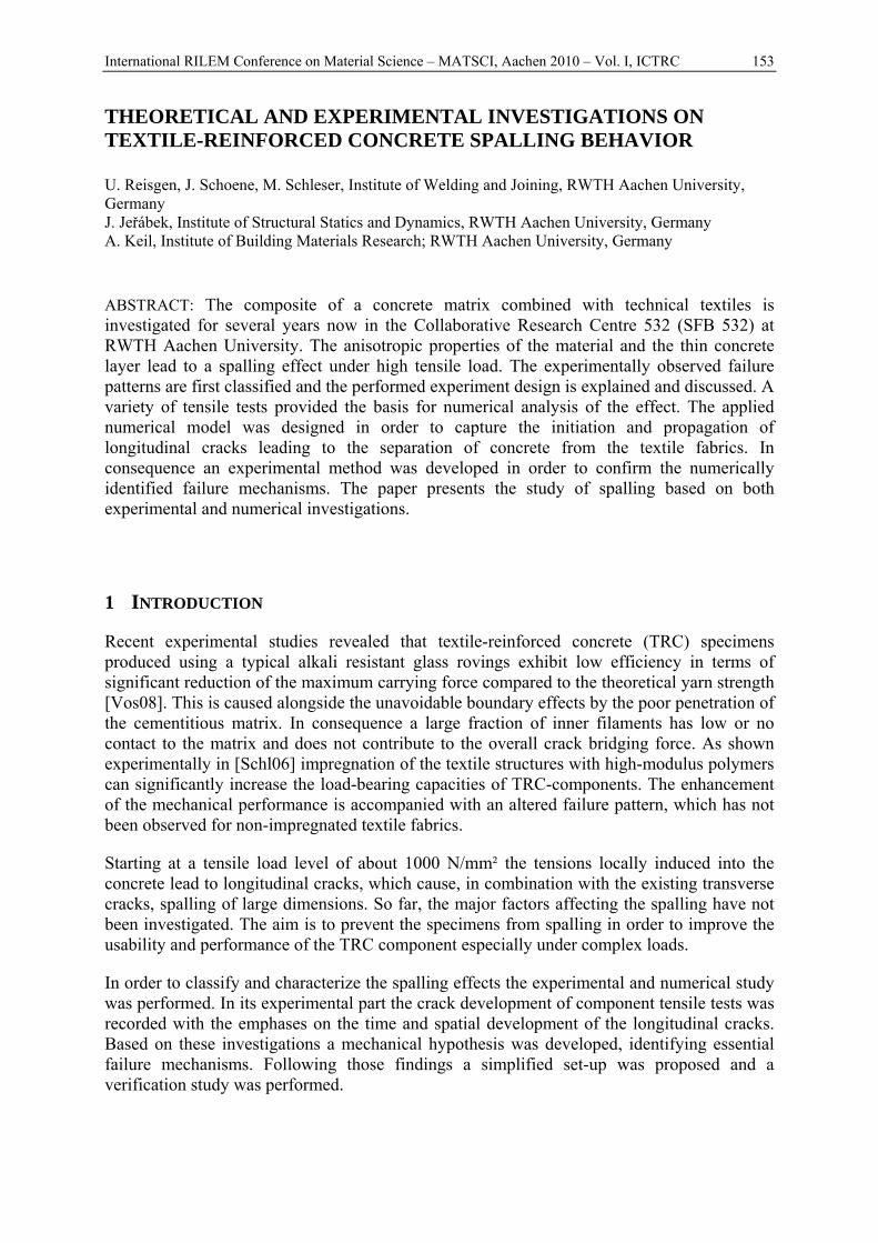
Table 2.1. Composition of fine grained concrete PZ 0899-01 Name Cement
(CEM I 52.5 R)
Fly ash (fa)
Silica fume (sf)
Sand < 0.6 mm
Quartz flour
Super-plastiziser
w/b =
w/(c+fa+sf) [-] kg/m³ %Σc+fa+sf
[-]
PZ 0899-01 490 175 35 714 499 1.5 0,4
3 EXPERIMENTAL PROGRAM
3.1 TSP-Test
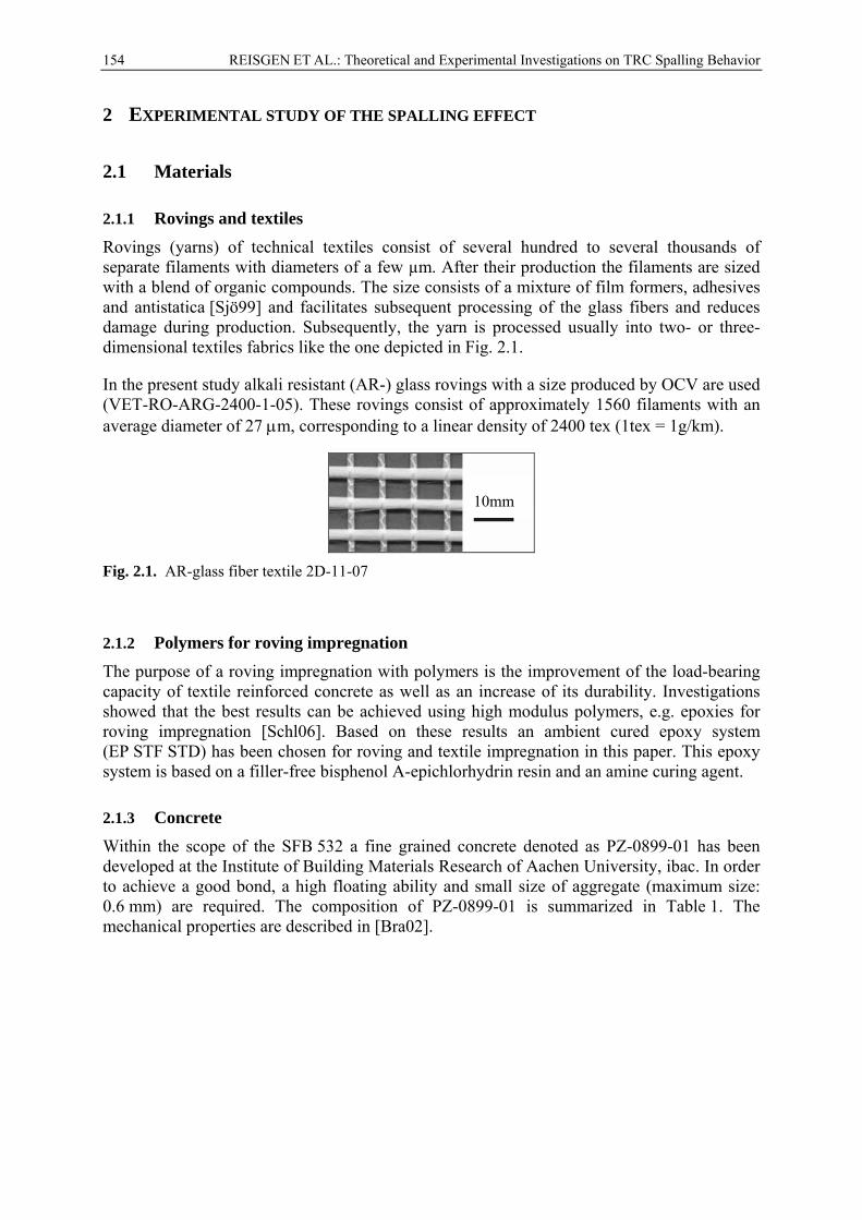
In order to investigate the tensile strength and bond quality of textile reinforced concrete, dog-bone shaped specimens (further referred to as TSP-specimens) have been produced. Either several detached rovings or a strip of the glass fibre textile are clamped centrally in a steel mold (500 x 100 x 6 m³) and embedded in the concrete mixture. For these investigations non-impregnated and impregnated reinforcement were used. The samples were stored for 28 days at 23 °C and 95 % relative humidity, and then 7 days at 23 °C and 50 % relative humidity. The tensile load was applied at a speed of 0.5 mm/min. The recorded response included the stress-strain curves and parallel monitoring of crack development and failure pattern during the loading with digital cameras. Pictures of the crack pattern were taken at each 0.5 kN. Three specimen replications were tested in each series. The experimental setup of the TSP-Test is shown in Fig. 3.1.
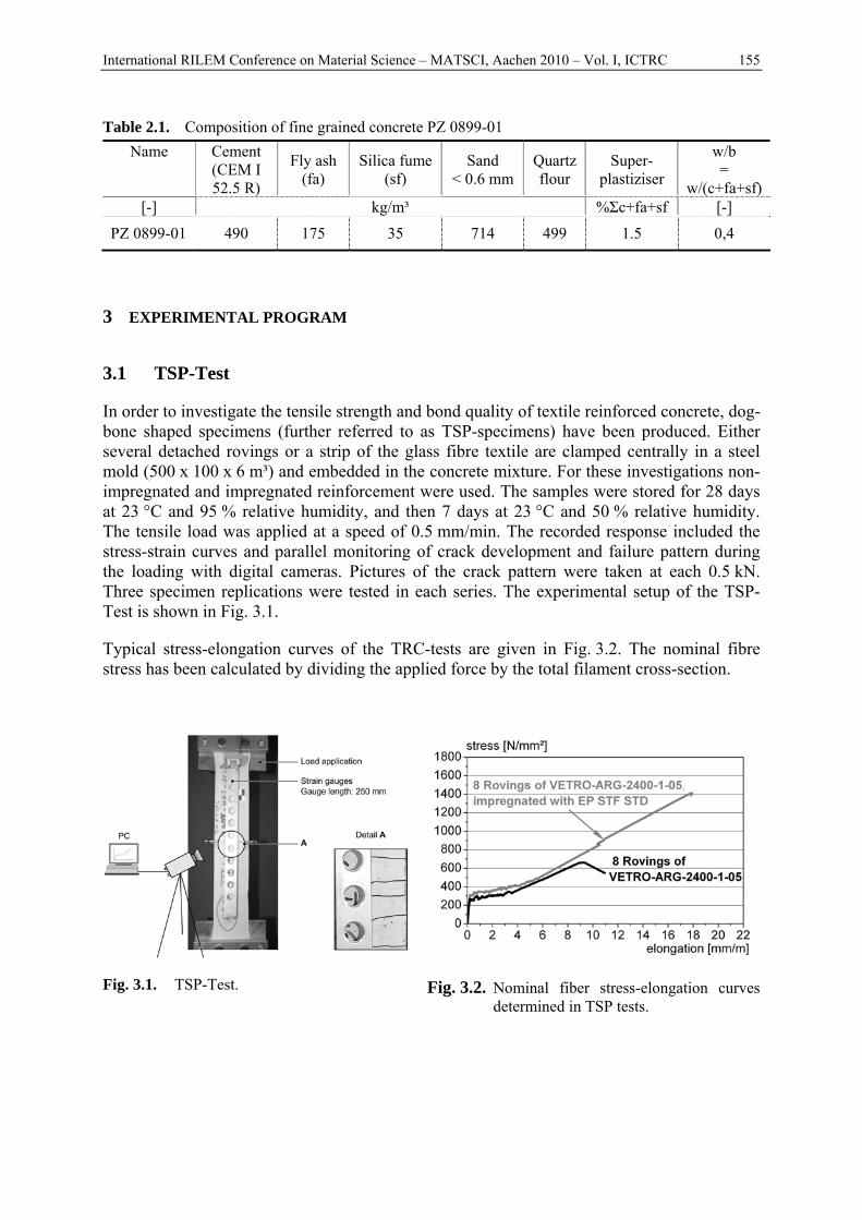
Typical stress-elongation curves of the TRC-tests are given in Fig. 3.2. The nominal fibre stress has been calculated by dividing the applied force by the total filament cross-section.
Fig. 3.1. TSP-Test. Fig. 3.2. Nominal fiber stress-elongation curves determined in TSP tests.
156 REISGEN ET AL.: Theoretical and Experimental Investigations on TRC Spalling Behavior
3.2 Discussion of test results
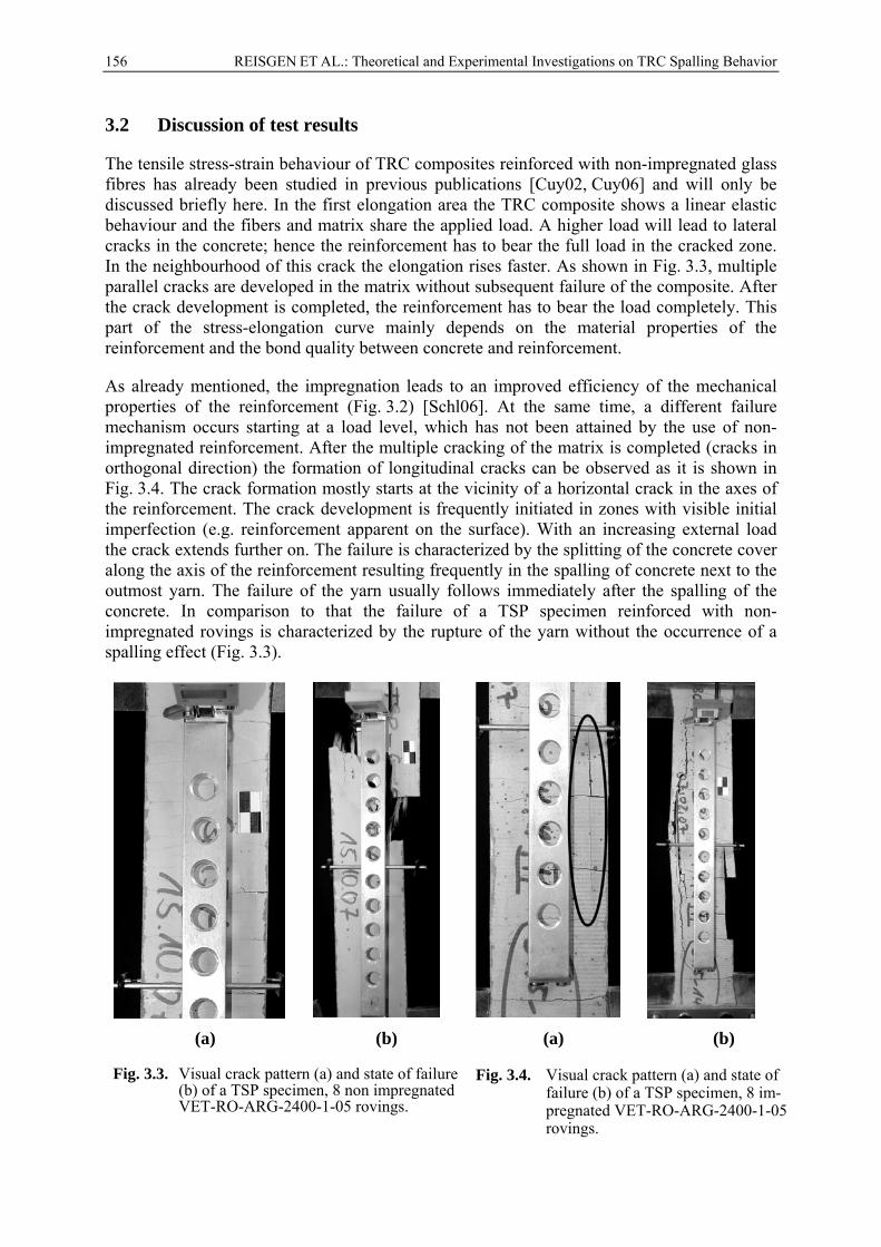
The tensile stress-strain behaviour of TRC composites reinforced with non-impregnated glass fibres has already been studied in previous publications [Cuy02, Cuy06] and will only be discussed briefly here. In the first elongation area the TRC composite shows a linear elastic behaviour and the fibers and matrix share the applied load. A higher load will lead to lateral cracks in the concrete; hence the reinforcement has to bear the full load in the cracked zone. In the neighbourhood of this crack the elongation rises faster. As shown in Fig. 3.3, multiple parallel cracks are developed in the matrix without subsequent failure of the composite. After the crack development is completed, the reinforcement has to bear the load completely. This part of the stress-elongation curve mainly depends on the material properties of the reinforcement and the bond quality between concrete and reinforcement.
As already mentioned, the impregnation leads to an improved efficiency of the mechanical properties of the reinforcement (Fig. 3.2) [Schl06]. At the same time, a different failure mechanism occurs starting at a load level, which has not been attained by the use of non-impregnated reinforcement. After the multiple cracking of the matrix is completed (cracks in orthogonal direction) the formation of longitudinal cracks can be observed as it is shown in Fig. 3.4. The crack formation mostly starts at the vicinity of a horizontal crack in the axes of the reinforcement. The crack development is frequently initiated in zones with visible initial imperfection (e.g. reinforcement apparent on the surface). With an increasing external load the crack extends further on. The failure is characterized by the splitting of the concrete cover along the axis of the reinforcement resulting frequently in the spalling of concrete next to the outmost yarn. The failure of the yarn usually follows immediately after the spalling of the concrete. In comparison to that the failure of a TSP specimen reinforced with non-impregnated rovings is characterized by the rupture of the yarn without the occurrence of a spalling effect (Fig. 3.3).
(a) (b) (a) (b)
Fig. 3.3. Visual crack pattern (a) and state of failure (b) of a TSP specimen, 8 non impregnated VET-RO-ARG-2400-1-05 rovings.
Fig. 3.4. Visual crack pattern (a) and state of failure (b) of a TSP specimen, 8 im-pregnated VET-RO-ARG-2400-1-05 rovings.
International RILEM Conference on Material Science – MATSCI, Aachen 2010 – Vol. I, ICTRC 157
4 MODELLING OF THE LONGITUDINAL CRACK DEVELOPMENT
4.1 Mechanical idealization of the spalling effect
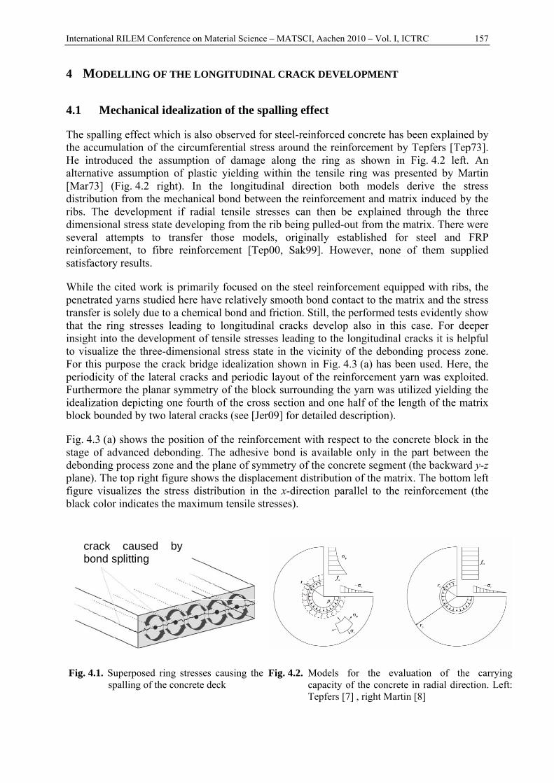
The spalling effect which is also observed for steel-reinforced concrete has been explained by the accumulation of the circumferential stress around the reinforcement by Tepfers [Tep73]. He introduced the assumption of damage along the ring as shown in Fig. 4.2 left. An alternative assumption of plastic yielding within the tensile ring was presented by Martin [Mar73] (Fig. 4.2 right). In the longitudinal direction both models derive the stress distribution from the mechanical bond between the reinforcement and matrix induced by the ribs. The development if radial tensile stresses can then be explained through the three dimensional stress state developing from the rib being pulled-out from the matrix. There were several attempts to transfer those models, originally established for steel and FRP reinforcement, to fibre reinforcement [Tep00, Sak99]. However, none of them supplied satisfactory results.
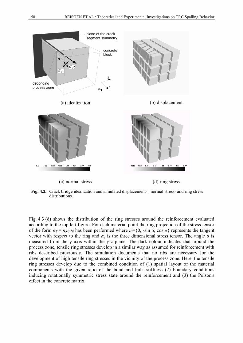
While the cited work is primarily focused on the steel reinforcement equipped with ribs, the penetrated yarns studied here have relatively smooth bond contact to the matrix and the stress transfer is solely due to a chemical bond and friction. Still, the performed tests evidently show that the ring stresses leading to longitudinal cracks develop also in this case. For deeper insight into the development of tensile stresses leading to the longitudinal cracks it is helpful to visualize the three-dimensional stress state in the vicinity of the debonding process zone. For this purpose the crack bridge idealization shown in Fig. 4.3 (a) has been used. Here, the periodicity of the lateral cracks and periodic layout of the reinforcement yarn was exploited. Furthermore the planar symmetry of the block surrounding the yarn was utilized yielding the idealization depicting one fourth of the cross section and one half of the length of the matrix block bounded by two lateral cracks (see [Jer09] for detailed description).
Fig. 4.3 (a) shows the position of the reinforcement with respect to the concrete block in the stage of advanced debonding. The adhesive bond is available only in the part between the debonding process zone and the plane of symmetry of the concrete segment (the backward y-z plane). The top right figure shows the displacement distribution of the matrix. The bottom left figure visualizes the stress distribution in the x-direction parallel to the reinforcement (the black color indicates the maximum tensile stresses).
crack caused by bond splitting
Fig. 4.1. Superposed ring stresses causing the spalling of the concrete deck
Fig. 4.2. Models for the evaluation of the carrying capacity of the concrete in radial direction. Left: Tepfers [7] , right Martin [8]
158 REISGEN ET AL.: Theoretical and Experimental Investigations on TRC Spalling Behavior
plane of the cracksegment symmetry
debondingprocess zone
concreteblock
x
z
y
α
(a) idealization
(b) displacement
(c) normal stress
(d) ring stress
Fig. 4.3. Crack bridge idealization and simulated displacement- , normal stress- and ring stress distributions.
Fig. 4.3 (d) shows the distribution of the ring stresses around the reinforcement evaluated according to the top left figure. For each material point the ring projection of the stress tensor of the form σT = ninjσij has been performed where ni={0, -sin α, cos α} represents the tangent vector with respect to the ring and σij is the three dimensional stress tensor. The angle α is measured from the y axis within the y-z plane. The dark colour indicates that around the process zone, tensile ring stresses develop in a similar way as assumed for reinforcement with ribs described previously. The simulation documents that no ribs are necessary for the development of high tensile ring stresses in the vicinity of the process zone. Here, the tensile ring stresses develop due to the combined condition of (1) spatial layout of the material components with the given ratio of the bond and bulk stiffness (2) boundary conditions inducing rotationally symmetric stress state around the reinforcement and (3) the Poison's effect in the concrete matrix.
International RILEM Conference on Material Science – MATSCI, Aachen 2010 – Vol. I, ICTRC 159
5 EXPERIMENTAL VALIDATION
5.1 Experimental set-up
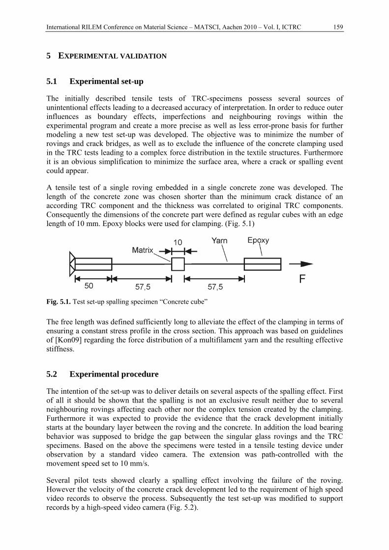
The initially described tensile tests of TRC-specimens possess several sources of unintentional effects leading to a decreased accuracy of interpretation. In order to reduce outer influences as boundary effects, imperfections and neighbouring rovings within the experimental program and create a more precise as well as less error-prone basis for further modeling a new test set-up was developed. The objective was to minimize the number of rovings and crack bridges, as well as to exclude the influence of the concrete clamping used in the TRC tests leading to a complex force distribution in the textile structures. Furthermore it is an obvious simplification to minimize the surface area, where a crack or spalling event could appear.
A tensile test of a single roving embedded in a single concrete zone was developed. The length of the concrete zone was chosen shorter than the minimum crack distance of an according TRC component and the thickness was correlated to original TRC components. Consequently the dimensions of the concrete part were defined as regular cubes with an edge length of 10 mm. Epoxy blocks were used for clamping. (Fig. 5.1)
Fig. 5.1. Test set-up spalling specimen “Concrete cube”
The free length was defined sufficiently long to alleviate the effect of the clamping in terms of ensuring a constant stress profile in the cross section. This approach was based on guidelines of [Kon09] regarding the force distribution of a multifilament yarn and the resulting effective stiffness.
5.2 Experimental procedure
The intention of the set-up was to deliver details on several aspects of the spalling effect. First of all it should be shown that the spalling is not an exclusive result neither due to several neighbouring rovings affecting each other nor the complex tension created by the clamping. Furthermore it was expected to provide the evidence that the crack development initially starts at the boundary layer between the roving and the concrete. In addition the load bearing behavior was supposed to bridge the gap between the singular glass rovings and the TRC specimens. Based on the above the specimens were tested in a tensile testing device under observation by a standard video camera. The extension was path-controlled with the movement speed set to 10 mm/s.
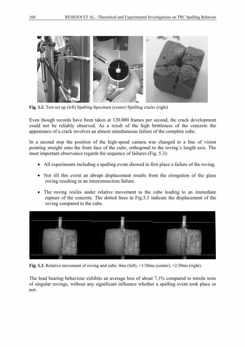
Several pilot tests showed clearly a spalling effect involving the failure of the roving. However the velocity of the concrete crack development led to the requirement of high speed video records to observe the process. Subsequently the test set-up was modified to support records by a high-speed video camera (Fig. 5.2).
160 REISGEN ET AL.: Theoretical and Experimental Investigations on TRC Spalling Behavior
Fig. 5.2. Test-set up (left) Spalling Specimen (center) Spalling cracks (right)
Even though records have been taken at 120.000 frames per second, the crack development could not be reliably observed. As a result of the high brittleness of the concrete the appearance of a crack involves an almost simultaneous failure of the complete cube.
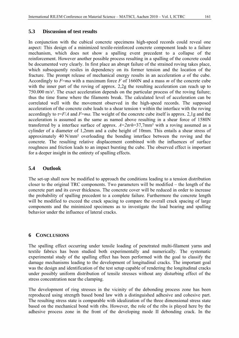
In a second step the position of the high-speed camera was changed to a line of vision pointing straight onto the front face of the cube, orthogonal to the roving´s length axis. The most important observance regards the sequence of failures (Fig. 5.3):
• All experiments including a spalling event showed in first place a failure of the roving.
• Not till this event an abrupt displacement results from the elongation of the glass roving resulting in an interconnection failure.
• The roving resiles under relative movement to the cube leading to an immediate rupture of the concrete. The dotted lines in Fig.5.3 indicate the displacement of the roving compared to the cube.
Fig. 5.3. Relative movement of roving and cube: 0ms (left), +1/30ms (center), +2/30ms (right).
The load bearing behaviour exhibits an average loss of about 7,1% compared to tensile tests of singular rovings, without any significant influence whether a spalling event took place or not.
International RILEM Conference on Material Science – MATSCI, Aachen 2010 – Vol. I, ICTRC 161
5.3 Discussion of test results
In conjunction with the cubical concrete specimens high-speed records could reveal one aspect: This design of a minimized textile-reinforced concrete component leads to a failure mechanism, which does not show a spalling event precedent to a collapse of the reinforcement. However another possible process resulting in a spalling of the concrete could be documented very clearly. In first place an abrupt failure of the strained roving takes place, which subsequently resiles in dependency on its former tension and the location of the fracture. The prompt release of mechanical energy results in an acceleration a of the cube. Accordingly to F=ma with a maximum force F of 1660N and a mass m of the concrete cube with the inner part of the roving of approx. 2,2g the resulting acceleration can reach up to 750.000 m/s². The exact acceleration depends on the particular process of the roving failure; thus the time frame where the filaments break. The calculated level of acceleration can be correlated well with the movement observed in the high-speed records. The supposed acceleration of the concrete cube leads to a shear tension τ within the interface with the roving accordingly to τ=F/A and F=ma. The weight of the concrete cube itself is approx. 2,1g and the acceleration is assumed as the same as named above resulting in a shear force of 1580N transferred by a interface surface of approx. A=2πrh=37,7mm² with a roving assumed as a cylinder of a diameter of 1,2mm and a cube height of 10mm. This entails a shear stress of approximately 40 N/mm² overloading the bonding interface between the roving and the concrete. The resulting relative displacement combined with the influences of surface roughness and friction leads to an impact bursting the cube. The observed effect is important for a deeper insight in the entirety of spalling effects.
5.4 Outlook
The set-up shall now be modified to approach the conditions leading to a tension distribution closer to the original TRC components. Two parameters will be modified – the length of the concrete part and its cover thickness. The concrete cover will be reduced in order to increase the probability of spalling precedent to a complete failure. Furthermore the concrete length will be modified to exceed the crack spacing to compare the overall crack spacing of large components and the minimized specimens as to investigate the load bearing and spalling behavior under the influence of lateral cracks.
6 CONCLUSIONS
The spalling effect occurring under tensile loading of penetrated multi-filament yarns and textile fabrics has been studied both experimentally and numerically. The systematic experimental study of the spalling effect has been performed with the goal to classify the damage mechanisms leading to the development of longitudinal cracks. The important goal was the design and identification of the test setup capable of rendering the longitudinal cracks under possibly uniform distribution of tensile stresses without any disturbing effect of the stress concentration near the clamping.
The development of ring stresses in the vicinity of the debonding process zone has been reproduced using strength based bond law with a distinguished adhesive and cohesive part. The resulting stress state is comparable with idealization of the three dimensional stress state based on the mechanical bond with ribs. However, the role of the ribs is played here by the adhesive process zone in the front of the developing mode II debonding crack. In the
162 REISGEN ET AL.: Theoretical and Experimental Investigations on TRC Spalling Behavior
presented simulation the anisotropic damage model applied for the concrete could reproduce the development of longitudinal crack. Thus, it can be regarded as feasible for detecting the combinations of component material parameters with a proneness to spalling.
The model also motivated to the substantial change of the experimentals. The “concrete cube” test set-up, with highly simplified geometry and loading conditions was designed. The high-speed video records of perform experiments showed the sequence of failure for the described cubic specimen, nevertheless the process of longitudinal crack development could not be verified. The effect of spalling taking place after the failure of the glass roving could be monitored and its cause illuminated. The experimental set-up shall be modified to enable observations on the crack development.
ACKNOWLEDGMENT
The work has been supported by Deutsche Forschungsgemeinschaft (DFG) in the framework of the collaborative research center SFB 532 Textile-reinforced concrete, development of a new technology. The support is gratefully acknowledged.
REFERENCES
[Vos08] S. Voss, Ingenieurmodelle zum Tragverhalten von Textilbewehrtem Beton. PhD., RWTH Aachen, Aachen (2008)
[Schl06] Schleser, M., Walk-Lauffer, B., Raupach, M., Dilthey, U., Application of Polymers to Textile-Reinforced Concrete, Journal of Materials in Civil Engineering, 18(5), 670-676 (2006)
[Sjö99] Sjögren, A., Joffe, R., Berlund, L., and Mäder, E., Effects of Fibre Coating (Size) on Properties of Glass/Vinyl Ester Composite, Composites, Part A: Applied Science and Manufactur, 30, (1999)
[Bra02] Brameshuber, W.; Brockmann, T.; Hegger J.; Molter, M.: Untersuchungen zum textilbewehrten Beton. Beton 52 (2002) Nr. 9, S. 424-429
[Cuy06] H. Cuypers, J. Wastiels, A stochastic matrix cracking theory for glass-fibre reinforced cementitious composites, Materials and Structures, Vol 39 (292), (2006) 777-786
[Cuy02] H. Cuypers, Analysis and Design of Sandwich Panels with Brittle Matrix Composite Faces for Building Applications. PhD., Vrije Universiteit Brussel, Brussels (2002)
[Tep73] R. Tepfers, A theory of bond applied to tensile reinforcement splices for deformed bars. PhD., Chalmers University of Technology, Göteborg (1973)
[Mar73] H. Martin, Zusammenhang zwischen Oberflächenbeschaffenheit, Verbund und Sprengwirkung von Bewehrungsstählen unter Kurzzeitbelastung. Deutsche Ausschuss für Stahlbeton, Heft 228, Berlin(1973)
[Tep00] R. Tepfers, E. Cosenza, J. Modniks et al. Bond of nonmetalic Reinforcement. In: Task Group Bond Models fib (CEP-FIP), Bond of reinforcement in concrete (Bulletin 10), Stuttgart (2000)
[Sak99] T. Sakai, T Kanakubo, K. Yonemaru et al. Bond Splitting Behavior of Continuous Fiber Reinforced Concrete Members. In: Fiber Reinforced Polymer for Reinforced Concrete Structure Structures, (1999)
[Kon08] M. Konrad, Effect of multifilament yarn crack bridging on uniaxial behavior of textile reinforced concrete. PhD., RWTH Aachen, Aachen (2008)
[Leu02] M. Leukart, E. Ramm, An Alternative Split within the Microplane Material Model,. In Proceedings: WCCM V FifthWorld Congress on Computational Mechanics (2002)
[Kon09] M. Konrad, R. Chudoba, Tensile behavior of cementitious composite reinforced with epoxy impregnated multifilament yarns. International Journal for Multiscale Computational Engineering, Band 7, No. 2, Pg. 115-133, 2009
Related Documents