Theoretical Analysis of the Performance of One-Dimensional Photonic Crystal-Based Dye-Sensitized Solar Cells Gabriel Lozano, Silvia Colodrero, Ophelie Caulier, Mauricio E. Calvo, and Herna ´n Mı ´guez* Instituto de Ciencia de Materiales de SeVilla, Consejo Superior de InVestigaciones Cientı ´ficas-UniVersidad de SeVilla, Ame ´rico Vespucio 49, 41092 SeVilla, Spain ReceiVed: October 8, 2009; ReVised Manuscript ReceiVed: January 18, 2010 A simple analytical model that allows designing one-dimensional photonic crystal based dye sensitized solar cells of optimized performance, accounting for the actual optical features of the device, is herein presented. Based on the theoretical description of the effect of coupling such Bragg mirrors to the light harvesting electrode, recently reported experimental values of the spectral dependence of incident photon to current conversion efficiency attained for such structures are fairly reproduced and rationalized. A thorough analysis of them in terms of the interplay between the effect of the electrode thickness and the characteristics of the Bragg reflection, such as intensity, spectral position, and width, is provided. Predictions on the maximum enhancement factors expected for realistic structures are also presented. Introduction The positive effect of coupling a photonic crystal to an absorbing electrode on power conversion efficiency has been demonstrated for a number of solar cells in the last years. 1–7 The different physical mechanisms of enhancement have been thoroughly analyzed theoretically. 8–10 Very recently, a significant increase of both light harvesting efficiency (LHE) and power conversion efficiency has been observed in dye-sensitized electrodes coupled to highly reflecting porous nanoparticle based one-dimensional photonic crystals (1DPCs), which act as coherent scattering layers. 11,12 This approach, although not optimized yet, seeks to maximize the amount of light absorbed, while keeping some of the added values of the standard dye- sensitized solar cell, such as its semitransparency, which is lost when either a diffuse scattering layer or a metallic back mirror are used to enhance absorption. In this latter approach, besides, light must travel through a layer of absorbing electrolyte in which unproductive optical losses in terms of charge generation occur. On the other hand, 1DPCs are also capable of reflecting light of targeted wavelengths very intensely in spite of pos- sessing a small thickness (around 0.5 µm), so that no extra ohmic resistances that might cause a drop of the voltage are created. In fact, because the effect of the photonic crystal is similar to an increase of the photon flux, a rise of the open circuit photovoltage is expected, 13 although it has not been observed yet. It has been experimentally shown that enhancement of optical absorption is due to both the partial localization of photons of certain narrow frequency ranges as well as to the increase of the optical path within the absorbing layer, which result from its coupling to the photonic crystal. 12 However, it is still lacking a theoretical description that allows devising actual 1DPC based solar cells, which must take into account the interplay between the effect of the working electrode thickness, the amount of dye absorbed, and the characteristics (spectral width and intensity) of the Bragg reflection resulting from the coupled photonic structure. In this letter, we report on theoretical simulations of both the optical reflectance and the incident photon to current conversion efficiency (IPCE) of porous one-dimensional pho- tonic crystal-based dye-sensitized solar cells (DSSC). An analytical model that accounts for the actual optical features of the device is proposed. Its validity is confirmed by comparing its predictions with recently reported experimental values of the spectral dependence of the photogenerated current attained for such structures, which are fairly reproduced and rationalized. It is demonstrated that the interplay between the optical effect of the electrode thickness and the scattering strength of the photonic crystal determines the basic features of the performance of the cell and must be considered to design an optimized device. Predictions on the maximum enhancement factors expected for realistic structures are also presented. Theoretical Model. Both the actual dye-sensitized electrode and the porous 1DPC are consecutively deposited onto a conducting fluorinated tin-oxide-coated transparent substrate. First, a layer of nanocrystalline titanium dioxide (TiO 2 ) particles was deposited onto a conducting transparent substrate by doctor blade, spin-coating, or a combination of both techniques. A course rough layer was attained through the former, but a uniform and smooth surface was achieved in the final coating after a drop of a suspension of fine TiO 2 particles was spun onto it. Then, to build the Bragg reflector onto this coated substrate, layers of SiO 2 and TiO 2 particles were deposited alternately by spin-coating so that a periodic modulation of the refractive index is built up in the direction perpendicular to the electrode surface. Optical interference effects occurring between the beams reflected and transmitted at the different interfaces created are at the origin of the photonic crystal properties of this type of periodic nanostructures. After performing the usual thermal annealing and sensitization processes, the cell is completed using a metal-covered counterelectrode and the internal space between the electrodes is filled with a liquid redox electrolyte that at the same time soaks the porous photonic crystal, thus yielding electrical contact between the different parts of the cell. This ensemble is herein modeled through a layered structure, as depicted in Figure 1, in which the notation used in the simulation to represent the thickness and refractive index of each relevant slab is included. The incoming and outgoing media are considered to be the upper and lower glass * Corresponding author. E-mail: [email protected]. J. Phys. Chem. C 2010, 114, 3681–3687 3681 10.1021/jp9096315 2010 American Chemical Society Published on Web 02/09/2010

Welcome message from author
This document is posted to help you gain knowledge. Please leave a comment to let me know what you think about it! Share it to your friends and learn new things together.
Transcript
Theoretical Analysis of the Performance of One-Dimensional Photonic Crystal-BasedDye-Sensitized Solar Cells
Gabriel Lozano, Silvia Colodrero, Ophelie Caulier, Mauricio E. Calvo, and Hernan Mıguez*Instituto de Ciencia de Materiales de SeVilla, Consejo Superior de InVestigaciones Cientıficas-UniVersidad deSeVilla, Americo Vespucio 49, 41092 SeVilla, Spain
ReceiVed: October 8, 2009; ReVised Manuscript ReceiVed: January 18, 2010
A simple analytical model that allows designing one-dimensional photonic crystal based dye sensitized solarcells of optimized performance, accounting for the actual optical features of the device, is herein presented.Based on the theoretical description of the effect of coupling such Bragg mirrors to the light harvestingelectrode, recently reported experimental values of the spectral dependence of incident photon to currentconversion efficiency attained for such structures are fairly reproduced and rationalized. A thorough analysisof them in terms of the interplay between the effect of the electrode thickness and the characteristics of theBragg reflection, such as intensity, spectral position, and width, is provided. Predictions on the maximumenhancement factors expected for realistic structures are also presented.
Introduction
The positive effect of coupling a photonic crystal to anabsorbing electrode on power conversion efficiency has beendemonstrated for a number of solar cells in the last years.1–7
The different physical mechanisms of enhancement have beenthoroughly analyzed theoretically.8–10 Very recently, a significantincrease of both light harvesting efficiency (LHE) and powerconversion efficiency has been observed in dye-sensitizedelectrodes coupled to highly reflecting porous nanoparticle basedone-dimensional photonic crystals (1DPCs), which act ascoherent scattering layers.11,12 This approach, although notoptimized yet, seeks to maximize the amount of light absorbed,while keeping some of the added values of the standard dye-sensitized solar cell, such as its semitransparency, which is lostwhen either a diffuse scattering layer or a metallic back mirrorare used to enhance absorption. In this latter approach, besides,light must travel through a layer of absorbing electrolyte inwhich unproductive optical losses in terms of charge generationoccur. On the other hand, 1DPCs are also capable of reflectinglight of targeted wavelengths very intensely in spite of pos-sessing a small thickness (around 0.5 µm), so that no extra ohmicresistances that might cause a drop of the voltage are created.In fact, because the effect of the photonic crystal is similar toan increase of the photon flux, a rise of the open circuitphotovoltage is expected,13 although it has not been observedyet. It has been experimentally shown that enhancement ofoptical absorption is due to both the partial localization ofphotons of certain narrow frequency ranges as well as to theincrease of the optical path within the absorbing layer, whichresult from its coupling to the photonic crystal.12 However, itis still lacking a theoretical description that allows devisingactual 1DPC based solar cells, which must take into accountthe interplay between the effect of the working electrodethickness, the amount of dye absorbed, and the characteristics(spectral width and intensity) of the Bragg reflection resultingfrom the coupled photonic structure.
In this letter, we report on theoretical simulations of boththe optical reflectance and the incident photon to current
conversion efficiency (IPCE) of porous one-dimensional pho-tonic crystal-based dye-sensitized solar cells (DSSC). Ananalytical model that accounts for the actual optical features ofthe device is proposed. Its validity is confirmed by comparingits predictions with recently reported experimental values of thespectral dependence of the photogenerated current attained forsuch structures, which are fairly reproduced and rationalized.It is demonstrated that the interplay between the optical effectof the electrode thickness and the scattering strength of thephotonic crystal determines the basic features of the performanceof the cell and must be considered to design an optimized device.Predictions on the maximum enhancement factors expected forrealistic structures are also presented.
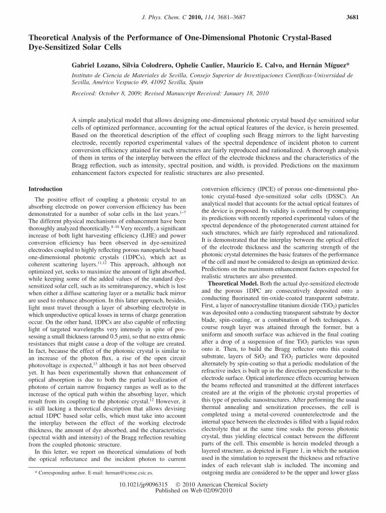
Theoretical Model. Both the actual dye-sensitized electrodeand the porous 1DPC are consecutively deposited onto aconducting fluorinated tin-oxide-coated transparent substrate.First, a layer of nanocrystalline titanium dioxide (TiO2) particleswas deposited onto a conducting transparent substrate by doctorblade, spin-coating, or a combination of both techniques. Acourse rough layer was attained through the former, but auniform and smooth surface was achieved in the final coatingafter a drop of a suspension of fine TiO2 particles was spunonto it. Then, to build the Bragg reflector onto this coatedsubstrate, layers of SiO2 and TiO2 particles were depositedalternately by spin-coating so that a periodic modulation of therefractive index is built up in the direction perpendicular to theelectrode surface. Optical interference effects occurring betweenthe beams reflected and transmitted at the different interfacescreated are at the origin of the photonic crystal properties ofthis type of periodic nanostructures. After performing the usualthermal annealing and sensitization processes, the cell iscompleted using a metal-covered counterelectrode and theinternal space between the electrodes is filled with a liquid redoxelectrolyte that at the same time soaks the porous photoniccrystal, thus yielding electrical contact between the differentparts of the cell. This ensemble is herein modeled through alayered structure, as depicted in Figure 1, in which the notationused in the simulation to represent the thickness and refractiveindex of each relevant slab is included. The incoming andoutgoing media are considered to be the upper and lower glass* Corresponding author. E-mail: [email protected].
J. Phys. Chem. C 2010, 114, 3681–3687 3681
10.1021/jp9096315 2010 American Chemical SocietyPublished on Web 02/09/2010
substrates, respectively. This is done to prevent the appearanceof very short period (<1 nm) fringes arising from the presenceof thick (>5 mm) entrance and exit plane parallel slabs, whichlargely make difficult the analysis of the relevant optical data.This effect is illustrated and analyzed in the SupportingInformation. Such ripples are usually not detectable experimen-tally since they are blurred by the lack of homogeneity of the
substrate thickness at the few nanometres length scale. In ourmodel, we also take into account the optical effects due to thepresence of the transparent conducting oxide coating, whosethickness and refractive index are dTCO and nTCO, respectively.The dyed nanocrystalline slab that acts as the cell workingelectrode presents as relevant parameters its thickness, dWE, andits complex refractive index, nWE, given by the expression:
The real part of the refractive index, nTiO2, is determined by
the refractive index of the TiO2 nanocrystals and the liquidelectrolyte filling the pore space between them. We assume thatthe imaginary part of the refractive index of the workingelectrode is mainly determined by the ruthenium dye becauseits molar absorption coefficient in the spectral region of interestis between 1 and 2 orders of magnitude larger than that of theelectrolyte,14 and their concentration in the electrode is similar.15
This allows us to establish a direct relation between theabsorptance of the cell and the light harvesting efficiency thatcontributes effectively to the photocurrent. The frequency-dependent imaginary part of the refractive index of the dyednc-TiO2 layer used in the calculations is:
Figure 1. Scheme of a DSSC coupled to a 1DPC showing the illumina-tion through the dye-coated TiO2 layer (frontal illumination).
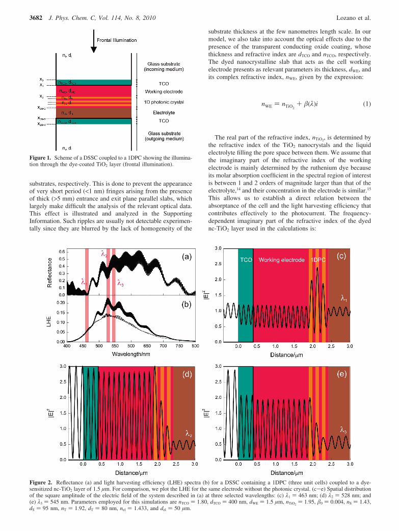
Figure 2. Reflectance (a) and light harvesting efficiency (LHE) spectra (b) for a DSSC containing a 1DPC (three unit cells) coupled to a dye-sensitized nc-TiO2 layer of 1.5 µm. For comparison, we plot the LHE for the same electrode without the photonic crystal. (c-e) Spatial distributionof the square amplitude of the electric field of the system described in (a) at three selected wavelengths: (c) λ1 ) 463 nm; (d) λ2 ) 528 nm; and(e) λ3 ) 545 nm. Parameters employed for this simulations are nTCO ) 1.80, dTCO ) 400 nm, dWE ) 1.5 µm, nTiO2
) 1.95, �0 ) 0.004, nS ) 1.43,dS ) 95 nm, nT ) 1.92, dT ) 80 nm, nel ) 1.433, and del ) 50 µm.
nWE ) nTiO2+ �(λ)i (1)
3682 J. Phys. Chem. C, Vol. 114, No. 8, 2010 Lozano et al.
which is the result of fitting the photocurrent and absorptancedata reported for similar electrodes in the literature.1,8 Pleasenotice that �0 can be related to the amount of dye adsorbedonto the titanium dioxide nanocrystals, whereas z(λ) dependson the specific sensitizer dye employed; in our case, for aruthenium bipyridyl complex, λ0 ) 538 nm, and ∆λ ) 64.16nm. Thus, different dye loads of the electrode can be simulatedthrough variations of �0.
The rest of slabs forming the modeled cell, that is, thenanoparticle SiO2 and TiO2 films the photonic crystal is madeof, and the space filled by the electrolyte are characterized bytheir respective thickness and refractive index, namely, (dS, nS),(dT, nT), and (del, nel). Thus, the porous nanoparticle basedphotonic crystal is simulated by the alternate stack of severalslabs characterized by the parameters (dS, nS) and (dT, nT). Aunit cell is formed by one pair of these slabs. In our case, wehave simulated the effect of photonic crystals whose thicknessranges from N ) 3 to N ) 10, where N is the number of unitcells. Both nS and nT are estimated considering that the poresof the SiO2 and TiO2 layers, respectively, are fully filled by theelectrolyte solution.
Our theoretical model should serve, in the first place, todescribe the optical reflectance (R) and incident photon to currentconversion efficiency (IPCE) values that have been reported inrefs 11 and 12. As in those experiments, in our simulation theincoming radiation impinges perpendicularly to the workingelectrode (frontal illumination conditions) and therefore to thestacking of dielectric layers. The electric field is treated as ascalar rather than a vector wave and it is considered to dependon just one spatial variable (x). Such simplified scalar waveapproximation (SWA) have proven to provide a good descriptionof the optical response of photonic crystals for specific directionsand at low energy ranges,16 as it is actually the case under studyhere.
To attain the R and the IPCE, it is necessary to calculate thereflection and transmission coefficients of the fields in theincident and outgoing media, labeled as r and t, respectively.Because partially transmitted and reflected waves are generatedat each interface present in the multilayer, the expressions forthe electric field in each one of the slabs is
with
where ki, kTCO, kWE, kS, kT, kel, and kt are the wavevectors in thehomogeneous incident medium, the transparent conducting oxidecoating, the working electrode, the silica and titania layersforming the photonic crystal (PC), the electrolyte, and theoutgoing media, respectively. Please notice that, except for thefinal transmission medium, in all the rest of the slabs considered,the electric field is taken to be the sum of a propagating and acounter-propagating wave, with similar wavevectors but oppositedirection and amplitude, given by the coefficients labeled,generically, as Cj. Please notice that the wavevector is givenby the general expression:17
in which the refractive index may be complex and frequencydependent.
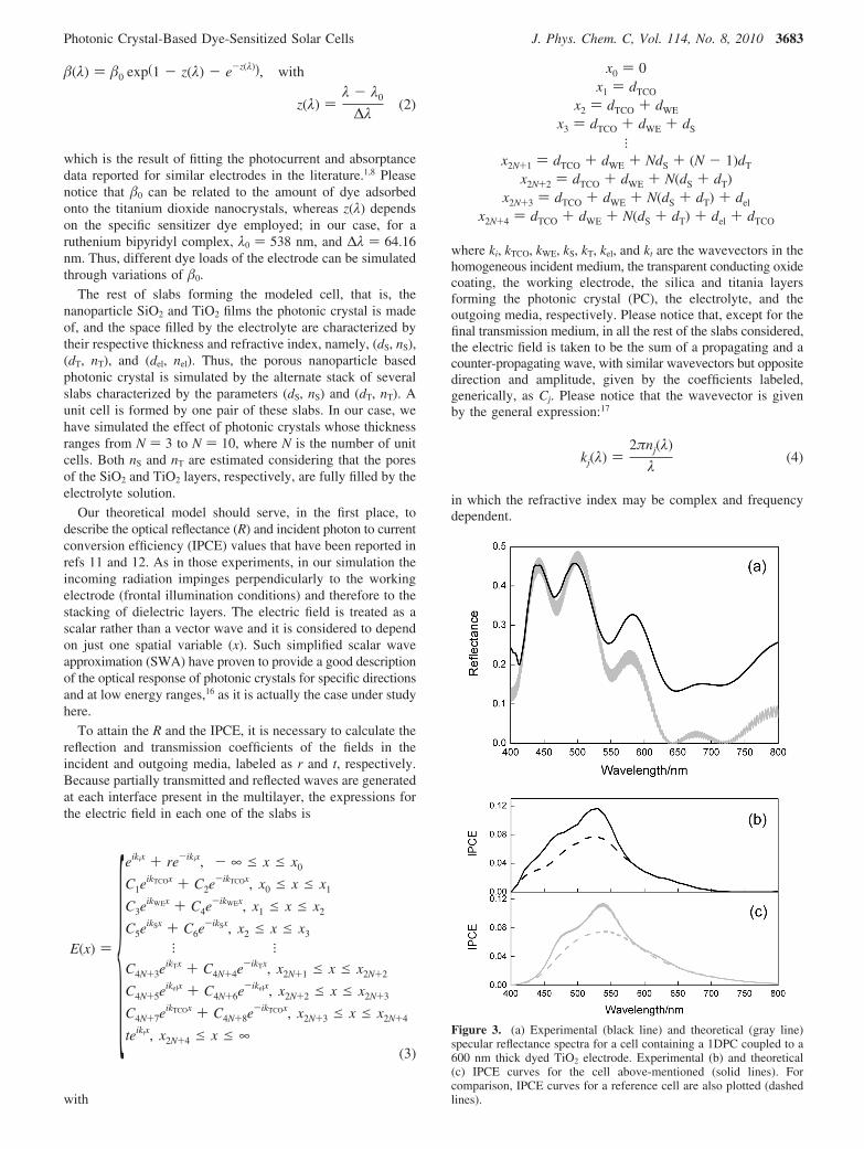
Figure 3. (a) Experimental (black line) and theoretical (gray line)specular reflectance spectra for a cell containing a 1DPC coupled to a600 nm thick dyed TiO2 electrode. Experimental (b) and theoretical(c) IPCE curves for the cell above-mentioned (solid lines). Forcomparison, IPCE curves for a reference cell are also plotted (dashedlines).
�(λ) ) �0 exp(1 - z(λ) - e-z(λ)), with
z(λ) )λ - λ0
∆λ(2)
E(x) ) {eikix + re-ikix, - ∞ e x e x0
C1eikTCOx + C2e
-ikTCOx, x0 e x e x1
C3eikWEx + C4e
-ikWEx, x1 e x e x2
C5eikSx + C6e
-ikSx, x2 e x e x3
l lC4N+3e
ikTx + C4N+4e-ikTx, x2N+1 e x e x2N+2
C4N+5eikelx + C4N+6e
-ikelx, x2N+2 e x e x2N+3
C4N+7eikTCOx + C4N+8e
-ikTCOx, x2N+3 e x e x2N+4
teiktx, x2N+4 e x e ∞(3)
x0 ) 0x1 ) dTCO
x2 ) dTCO + dWE
x3 ) dTCO + dWE + dS
lx2N+1 ) dTCO + dWE + NdS + (N - 1)dT
x2N+2 ) dTCO + dWE + N(dS + dT)x2N+3 ) dTCO + dWE + N(dS + dT) + del
x2N+4 ) dTCO + dWE + N(dS + dT) + del + dTCO
kj(λ) )2πnj(λ)
λ(4)
Photonic Crystal-Based Dye-Sensitized Solar Cells J. Phys. Chem. C, Vol. 114, No. 8, 2010 3683
The frequency-dependent coefficients r, t, and Cj are determined by imposing continuity conditions for both the electric field andits first derivative across the interface from one medium to the next. This establishes a set of equations that we solve by making useof the transfer matrix formalism. This method allows determining only the coefficients relevant for each particular case (in this case,r and t), thus, largely reducing the computation time and permitting us to test a large number of structures. Under this formalism,the set of equations can be expressed:
If the electric field is known at the beginning of a layer, thefield at the end of the same layer can be derived from a simplematrix operation. A stack of layers can then be represented asa system matrix, which is the product of the individual matricescorresponding to each intermediate slab considered within thesystem. In this way, it can be directly obtained the relationbetween reflection (r) and transmission (t) coefficients of thefields in the incident and outgoing media:
Therefore, reflectance (R) and transmittance (T) are determinedusing the following relations:17
Finally, the light harvesting efficiency (LHE) or absorptance(A) is obtained by employing the well-known equation
The relation between the LHE of a dye-sensitized solar celland the IPCE is given by18
where Φ(λ) is the electron-transfer yield and �(λ) is the chargecollecting efficiency by the glass supported electrode. Theintegral of this expression weighted by the solar radiationspectrum yields the photogenerated short circuit current densityJSC:
where q is the electron charge and F(λ) is the ratio between thesolar spectral irradiance and the photon energy. The incrementof photocurrent density (∆JSC) attained when a 1DPC is coupledto a dyed nc-TiO2 electrode is defined as follows:
(1r ) ) M( t
0 ) ) [Mx0
i ]-1Mx0
f [Mx1
i ]-1Mx1
f [Mx2
i ]-1Mx2
f · · ·
[Mx2N+3
i ]-1Mx2N+3
f [Mx2N+4
i ]-1Mx2N+4
f ( t0 ) ) (m11 m12
m21 m22)( t
0 ) (6)
R ) |r|2 ) |m21
m11|2
T )nt
ni|t|2 )
nt
ni| 1m11
|2(7)
LHE ) A ) 1 - R - T (8)
IPCE(λ) ) Φ(λ)�(λ)LHE(λ) (9)
JSC ) ∫ qIPCE(λ)F(λ)dλ (10)
3684 J. Phys. Chem. C, Vol. 114, No. 8, 2010 Lozano et al.
where LHEPC is the LHE of a DSSC coupled to a 1DPC,whereas LHEref refers to that of a DSSC used as reference. Forour calculations we use a simplified version of eq 11 in whichboth Φ(λ) and �(λ) are assumed to be constant and equal to 1.
The model herein proposed allows also calculating thestationary fields within the layered structure under analysis,which helps to visualize the effect of integrating the photoniccrystal on the actual spatial distribution of the radiation in thecell. In Figure 2a,b, we compare the simulated reflectancespectrum of a PC-based DSSC and its LHE with those of areference cell. It can be clearly seen the correspondence betweenspectral peaks of absorptance and dips in reflectance, which arethe fingerprint of optical resonant modes localized in the filmcoupled to the PC. It is important to point out that as thethickness of the dye-sensitized electrode increases, the numberof localized modes rises and so does the number of peaks inthe LHE curve. We have also calculated the spatial distributionof the squared magnitude of the electric field for three selectedfrequencies impinging under front-illumination conditions (pleasesee Figure 2c-e). These are chosen to illustrate the origin ofthe spectral response of the PC-based cell. For the sake of clarity,we have neglected the imaginary part of the refractive index ofthe dye, so the localization effects of the electric field can bebetter appreciated. It can be clearly seen that at the spectralposition where one of the dips in reflectance attributed to aresonant mode is found (λ2), localization is stronger within theelectrode than that observed for frequencies outside the bandgap (λ1) or at one of the reflectance peaks (λ3). The field intensitywithin the electrode for those frequencies lying within band gapfrequencies but not affected by localization (λ3) is also increasedas a result of being back-reflected by the 1DPC. Hence, althoughless efficient, it constitutes a second enhancement mechanismprovided by the 1DPC, as it was mentioned before.
Results and Discussion
To check the suitability of the proposed theoretical model,we use eqs 7 and 11 to calculate the R and the IPCE of 1DPC-based cells similar to those previously studied experimentallyin refs 11 and 12. In both cases, three unit cell photonic crystalswere implemented. Figure 3 shows the simulated (gray solidline) and experimental (black solid line) specular reflectanceand IPCE curves for a cell containing a SiO2-TiO2 nanoparticle-based 1DPC coupled to a 600 nm thick electrode made of dyedtitanium dioxide nanocrystallites, as reported in ref 12. Forcomparison, experimental and calculated data of the IPCE curvesobtained from a reference dye-sensitized TiO2 electrode of thesame thickness but with no photonic crystal coupled are alsoplotted (dashed black and gray lines) in Figure 3b and c,respectively. Good agreement between simulated and experi-mental reflectance spectra measured under frontal illuminationconditions is obtained, as displayed in Figure 3a, with both theshape and the intensity of the experimental optical features beingreproduced by the theoretical curve. This agreement evidencesthe high optical quality of the nanoparticle-based 1DPCs,because the fittings can be performed without considering theeffect of diffuse scattering. Dips in the reflectance spectrum ofthe cell indicate the presence of modes partially localized within
the working electrode.16 The values of the fitting parametersdefined in the previous section are, in this case, nTiO2
) 1.92,�0 ) 0.0055, nS ) 1.43, and nT ) 1.88.19 The lattice parameterof the periodic stack has been estimated to be 140 nm (dS ) 60nm, dT ) 80 nm). Please note that the amount of absorbingmaterial for the reference and the 1DPC-based cell is the same,which we simulate by keeping constant both the thickness andthe imaginary part (�0) of the refractive index of the layer thatsimulates the light absorbing electrode. In this case, and forthe rest of the calculations performed, we assume a layer ofelectrolyte of refractive index nel ) 1.43 and thickness del ) 50µm, although it was found that the results were basicallyindependent of del for thicknesses above 10 µm. Consideringthese parameters, the different IPCE curves attained for thereference and the PC-based solar cell are fairly reproduced bythe simulations, as clearly shown in Figure 3b,c. The photo-current enhancement is larger at the spectral regions at whichphotons are partially localized within the working electrode dueto the effect of the coupling to the 1DPC.
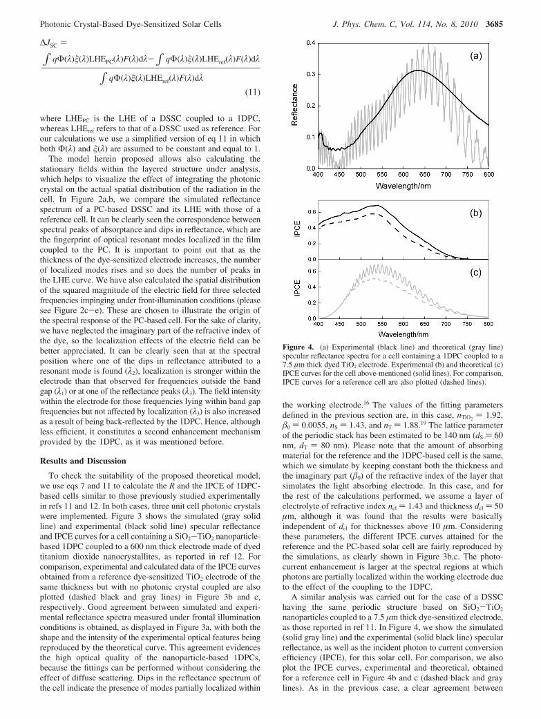
A similar analysis was carried out for the case of a DSSChaving the same periodic structure based on SiO2-TiO2
nanoparticles coupled to a 7.5 µm thick dye-sensitized electrode,as those reported in ref 11. In Figure 4, we show the simulated(solid gray line) and the experimental (solid black line) specularreflectance, as well as the incident photon to current conversionefficiency (IPCE), for this solar cell. For comparison, we alsoplot the IPCE curves, experimental and theoretical, obtainedfor a reference cell in Figure 4b and c (dashed black and graylines). As in the previous case, a clear agreement between
Figure 4. (a) Experimental (black line) and theoretical (gray line)specular reflectance spectra for a cell containing a 1DPC coupled to a7.5 µm thick dyed TiO2 electrode. Experimental (b) and theoretical (c)IPCE curves for the cell above-mentioned (solid lines). For comparison,IPCE curves for a reference cell are also plotted (dashed lines).
∆JSC )
∫ qΦ(λ)�(λ)LHEPC(λ)F(λ)dλ-∫ qΦ(λ)�(λ)LHEref(λ)F(λ)dλ
∫ qΦ(λ)�(λ)LHEref(λ)F(λ)dλ
(11)
Photonic Crystal-Based Dye-Sensitized Solar Cells J. Phys. Chem. C, Vol. 114, No. 8, 2010 3685
simulated and experimental reflectance spectra and IPCE curvesis observed. The simulated optical response and IPCE showmultiple optical resonance modes, which is a consequence ofcoupling a photonic crystal to a much thicker electrode, thus,creating multiple resonant frequencies partially localized withinthe absorbing electrode. These resonances are not easy todistinguish experimentally because they are blurred by the slightvariations of the electrode thickness. In this case, the latticeparameter of the 1DPC has been estimated to be 175 nm (dS )95 nm, dT ) 80 nm) and the values of the fitting parametersare now nTiO2
) 1.95, �0 ) 0.004, nS ) 1.43, and nT ) 1.92.Please notice that the value of the parameter �0, which we relateto the amount of dye adsorbed on the crystallites, is slightlysmaller in this latter case. This has been confirmed experimen-tally by performing desorption experiments on the actual cellsfollowing a reported procedure.20
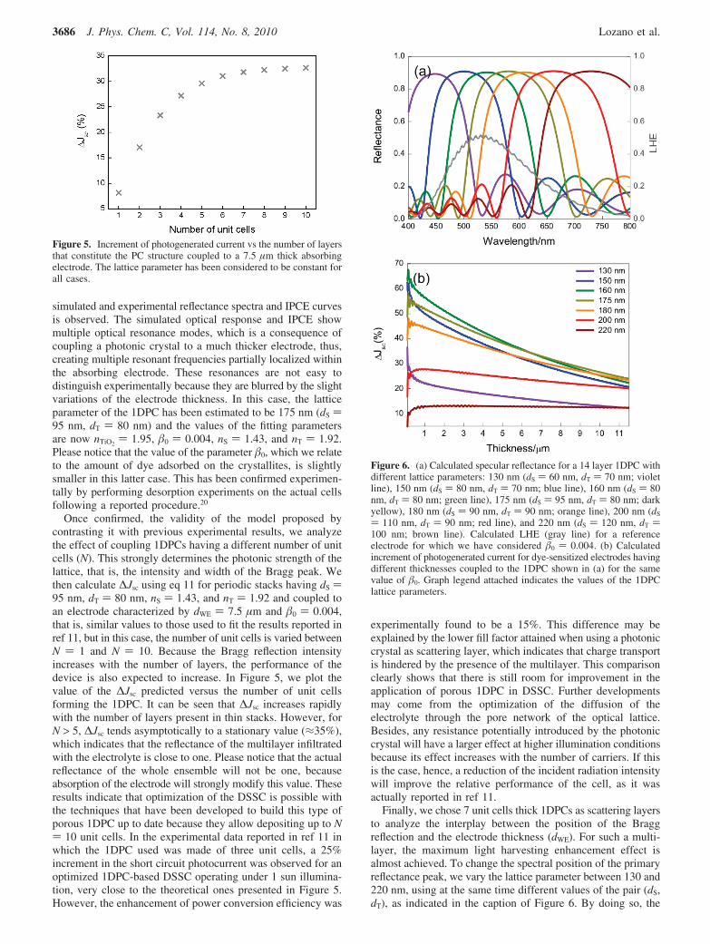
Once confirmed, the validity of the model proposed bycontrasting it with previous experimental results, we analyzethe effect of coupling 1DPCs having a different number of unitcells (N). This strongly determines the photonic strength of thelattice, that is, the intensity and width of the Bragg peak. Wethen calculate ∆Jsc using eq 11 for periodic stacks having dS )95 nm, dT ) 80 nm, nS ) 1.43, and nT ) 1.92 and coupled toan electrode characterized by dWE ) 7.5 µm and �0 ) 0.004,that is, similar values to those used to fit the results reported inref 11, but in this case, the number of unit cells is varied betweenN ) 1 and N ) 10. Because the Bragg reflection intensityincreases with the number of layers, the performance of thedevice is also expected to increase. In Figure 5, we plot thevalue of the ∆Jsc predicted versus the number of unit cellsforming the 1DPC. It can be seen that ∆Jsc increases rapidlywith the number of layers present in thin stacks. However, forN > 5, ∆Jsc tends asymptotically to a stationary value (≈35%),which indicates that the reflectance of the multilayer infiltratedwith the electrolyte is close to one. Please notice that the actualreflectance of the whole ensemble will not be one, becauseabsorption of the electrode will strongly modify this value. Theseresults indicate that optimization of the DSSC is possible withthe techniques that have been developed to build this type ofporous 1DPC up to date because they allow depositing up to N) 10 unit cells. In the experimental data reported in ref 11 inwhich the 1DPC used was made of three unit cells, a 25%increment in the short circuit photocurrent was observed for anoptimized 1DPC-based DSSC operating under 1 sun illumina-tion, very close to the theoretical ones presented in Figure 5.However, the enhancement of power conversion efficiency was
experimentally found to be a 15%. This difference may beexplained by the lower fill factor attained when using a photoniccrystal as scattering layer, which indicates that charge transportis hindered by the presence of the multilayer. This comparisonclearly shows that there is still room for improvement in theapplication of porous 1DPC in DSSC. Further developmentsmay come from the optimization of the diffusion of theelectrolyte through the pore network of the optical lattice.Besides, any resistance potentially introduced by the photoniccrystal will have a larger effect at higher illumination conditionsbecause its effect increases with the number of carriers. If thisis the case, hence, a reduction of the incident radiation intensitywill improve the relative performance of the cell, as it wasactually reported in ref 11.
Finally, we chose 7 unit cells thick 1DPCs as scattering layersto analyze the interplay between the position of the Braggreflection and the electrode thickness (dWE). For such a multi-layer, the maximum light harvesting enhancement effect isalmost achieved. To change the spectral position of the primaryreflectance peak, we vary the lattice parameter between 130 and220 nm, using at the same time different values of the pair (dS,dT), as indicated in the caption of Figure 6. By doing so, the
Figure 5. Increment of photogenerated current vs the number of layersthat constitute the PC structure coupled to a 7.5 µm thick absorbingelectrode. The lattice parameter has been considered to be constant forall cases.
Figure 6. (a) Calculated specular reflectance for a 14 layer 1DPC withdifferent lattice parameters: 130 nm (dS ) 60 nm, dT ) 70 nm; violetline), 150 nm (dS ) 80 nm, dT ) 70 nm; blue line), 160 nm (dS ) 80nm, dT ) 80 nm; green line), 175 nm (dS ) 95 nm, dT ) 80 nm; darkyellow), 180 nm (dS ) 90 nm, dT ) 90 nm; orange line), 200 nm (dS
) 110 nm, dT ) 90 nm; red line), and 220 nm (dS ) 120 nm, dT )100 nm; brown line). Calculated LHE (gray line) for a referenceelectrode for which we have considered �0 ) 0.004. (b) Calculatedincrement of photogenerated current for dye-sensitized electrodes havingdifferent thicknesses coupled to the 1DPC shown in (a) for the samevalue of �0. Graph legend attached indicates the values of the 1DPClattice parameters.
3686 J. Phys. Chem. C, Vol. 114, No. 8, 2010 Lozano et al.
peak sweeps the whole visible spectrum. To give it moregenerality, we have used different values of �0 (�0 ) 0.004, �0
) 0.0055, and �0 ) 0.008) to simulate three degrees of loadingof the dye in the structure, although all results shown in Figure6 correspond to �0 ) 0.004. In Figure 6a, we plot the calculatedabsorptance spectrum (LHE) corresponding to a 7.5 µm thickdyed electrode using such �0 (gray line). The results attainedfor the rest of �0 are included as Supporting Information.Superimposed, we draw the simulated reflectance of 1D periodicstructures with different lattice parameter (color lines) to showexplicitly the degree of overlap between the spectral regions inwhich high optical scattering and absorption occur. The ∆Jsc
attained for working electrodes of diverse dWE coupled to the1DPCs, whose Bragg reflections are plotted in Figure 6a, areshown in Figure 6b. It can be seen that the magnitude of thephotocurrent enhancement effect caused by the coupling tothe 1DPC lowers as the thickness of the electrode increases,because more photons are absorbed by the dyed nc-TiO2 layerwhen they first pass through it. Consequently, the effect ofincreasing the amount of absorbing material (�0) is also to reducethe enhancement factor due to the presence of the 1DPC (pleasesee Supporting Information). For thin electrodes, the highestenhancement factors are attained coupling 1DPCs whose Braggpeak overlaps most of the absorption band of the rutheniumdye. For thick electrodes, this trend changes and red reflecting1DPCs are found to perform better because the ruthenium dyeless effectively captures solar radiation precisely for λ > 600nm. Thus, once the rest of parameters (dWE, �0) have beenoptimized, it is in this spectral region where light harvestingmust be more strongly enhanced to improve conversion ef-ficiency. At the view of these curves, we can conclude that forstandard electrodes of 7 to 8 µm we can realistically expectenhancements of the photocurrent of 35% for optimized samples.Because the power conversion efficiency is directly proportionalto the short circuit photocurrent, similar enhancements may beexpected for the overall performance of the cell as long as therest of the parameters of the device are not altered by thepresence of the photonic crystal. For electrodes of thicknessessmaller than 3 µm, enhancements between 50 and 70% areexpected. These values, although very significant, are muchlower than those reported in ref 12 for the enhancement of thepower conversion efficiency of thin electrodes, which were ofeven a few hundred percent. Our calculations thus indicate thatsuch a difference cannot be entirely attributed to optical effects.
Conclusions
We have developed a simple analytical model that accuratelydescribes the enhancement effect on incident photon to currentconversion efficiency of a one-dimensional photonic crystalcoupled to a dye-sensitized electrode. By considering therealistic optical features of the device, recently reported experi-ments can be fairly reproduced and rationalized within thisapproach. The interplay between the effect of the electrodethickness and the position, width, and intensity of the Braggoptical reflection has been understood and shown to be critical
to optimize the device. Predictions on the maximum enhance-ment factors expected for realistic structures have also beenpresented.
Acknowledgment. This work has been funded by thecompany NLAB Solar, the Spanish Ministry of Science andEducation under Grant MAT2008-02166, Junta de Andalucıaunder Grant FQM3579, and Project HOPE (Consolider-Ingenio2010) CSD2007-00007. G.L. and M.C. thank the SpanishResearch Council for funding of their scholarships and contractsunder the JAE program.
Supporting Information Available: Calculated specularreflectance spectra for a 1DPC based DSSC in which the upperand lower glass substrates are considered finite and semi-infiniterespectively (Figure S1), and calculated increment of photoge-nerated current for dye-sensitized electrodes having differentthicknesses coupled to the 1DPC for �0 ) 0.0055 and �0 )0.008 (Figure S2). This material is available free of charge viathe Internet at http://pubs.acs.org.
References and Notes(1) Nishimura, S.; Abrams, V.; Lewis, B. A.; Halaoui, L.; Mallouk,
T. E.; Benkstein, K. D.; Lagemaat, J.; Frank, A. J. J. Am. Chem. Soc. 2003,125, 6306.
(2) O’Brien, P.; Kherani, N. P.; Zukotynski, S.; Ozin, G. A.; Vekris,E.; Tetreault, N.; Chutinan, A.; John, S.; Mihi, A.; Mıguez, H. AdV. Mater.2007, 19, 4177.
(3) Mihi, A.; Calvo, M. E.; Anta, J. A.; Mıguez, H. J. Phys. Chem. C2008, 112, 13.
(4) Ko, D. H.; Tumbleston, J. R.; Zhang, L.; Williams, S.; DeSimone,J. M.; Lopez, R.; Samulski, E. T. Nano Lett. 2009, 9, 2742.
(5) Prieto, I.; Galiana, B.; Postigo, P. A.; Algora, C.; Martınez, L. J.;Rey-Stolle, I. Appl. Phys. Lett. 2009, 94, 191102.
(6) Chang, T. H.; Wu, P. H.; Chen, S. H.; Chan, C. H.; Lee, C. C.;Chen, C. C.; Su, Y. K. Opt. Express 2009, 17, 6519.
(7) Zeng, L.; Yi, Y.; Hong, C.; Liu, J.; Feng, N.; Duan, X.; Kimerling,L. C.; Alamariu, B. A. Appl. Phys. Lett. 2006, 89, 111111.
(8) Mihi, A.; Mıguez, H. J. Phys. Chem. B. 2005, 109, 15968.(9) Bermel, P.; Luo, C.; Zeng, L.; Kimerling, L. C.; Joannopoulos,
J. D. Opt. Express 2007, 15, 16986.(10) Tumbleston, J. R.; Ko, D. H.; Samulski, E. T.; Lopez, R. Appl.
Phys. Lett. 2009, 94, 043305.(11) Colodrero, S.; Mihi, A.; Haggman, L.; Ocana, M.; Boschloo, G.;
Hagfeldt, A.; Mıguez, H. AdV. Mater. 2009, 21, 764.(12) Colodrero, S.; Mihi, A.; Anta, J. A.; Ocana, M.; Mıguez, H. J.
Phys. Chem. C 2009, 113, 1150.(13) Nelson, J. The Physics of Solar Cells; Imperial College Press:
London, 2003, ISBN 1860943403.(14) Awtrey, A. D.; Connick, R. E. J. Am. Chem. Soc. 1951, 73, 1842.(15) Gratzel, M. Inorg. Chem. 2005, 44, 6841.(16) Mihi, A.; Mıguez, H.; Rodrıguez, I.; Rubio, S.; Meseguer, F. Phys.
ReV. B 2005, 71, 125131.(17) Hecht, E.; Zajac, A. Optics Addison-Wesley Iberoamericana:
Argentina, 1986; ISBN 0201028395.(18) Tachibana, Y.; Hara, K.; Sayama, K.; Arakawa, H. Chem. Mater.
2002, 14, 2527.(19) We assume that the refractive indices of the titania and silica
particles are 2.44 and 1.43, respectively; the final values of nT and nS attainedfor the layers they form from the fittings are in good agreement with theexpected results of averaging the refractive index of the nanoparticles andthat of the interstitial volume filled with electrolyte using Bruggemanequation.
(20) Nakade, S.; Matsuda, M.; Kambe, S.; Saito, Y.; Kitamura, T.;Sakata, T.; Wada, Y.; Mori, H.; Yanagida, S. J. Phys. Chem. B 2002, 106,10004.
JP9096315
Photonic Crystal-Based Dye-Sensitized Solar Cells J. Phys. Chem. C, Vol. 114, No. 8, 2010 3687
Related Documents